Embed Size (px)
Citation preview

Topic: User’s Manual/Verification tests - EN1991-1-4_(b).xls page 273
Section 27 Eurocode 1EN 1991-1-4 Annex A
27.1 Terrain categories
llustrations of the upper roughness of each terrain category are given in Section A.1. The mean wind velocity at a height above the terrain depends
on the terrain roughness and orography and on the basic wind velocity. The terrain category are:
— terrain category 0: sea, coastal area exposed to the open sea
— terrain category I: lakes or area with negligible vegetation and without obstacles
— terrain category II: area with low vegetation such as grass and isolated obstacles (trees, buildings) with separations of at least 20 obstacle heights
— terrain category III: area with regular cover of vegetation or buildings or with isolated obstacles with separations of maximum 20 obstacle heights (such as villages, suburban terrain, permanent forest)
— terrain category IV: area in which at least 15% of the surface is covered with buildings and their average height exceeds 15 m.
27.2 Transition between roughness categories 0, I, II, III and IV
Two recommended procedures are given:
— Procedure 1
— Procedure 2.
PROCEDURE 1. If the structure is situated near a change of terrain roughness at a distance less than 2 km from the smoother category 0 or less than 1 km from the smoother categories I to III the smoother terrain category in the upwind direction should be used.
I z
EUROCODES SPREADSHEETS STRUCTURAL DESIGN SECTION 27 EUROCODE 1 EN 1991-1-4 ANNEX A
page 274 Topic: User’s Manual/Verification tests - EN1991-1-4_(b).xls
PROCEDURE 2. Determine the roughness categories for the upstream terrain in the angular sectors to be considered. For every angular sector, determine the distance from the building to the upstream roughness changes. If the distance
from the building to a terrain with lower roughness length is smaller than the values given in Table A.1, then the lower value for the roughness length should be used for the angular sector considered. If this distance is larger than the value in Table A.1, the higher value for the roughness length should be used. For intermediate values of height , linear interpolation may be used. Where no distance is given in Table A.1 or for heights exceeding 50 m, the smaller roughness length should be used.
Small areas (less than 10% of the area under consideration) with deviating roughness may be ignored in both procedures.
27.3 Numerical calculation of orography coefficients
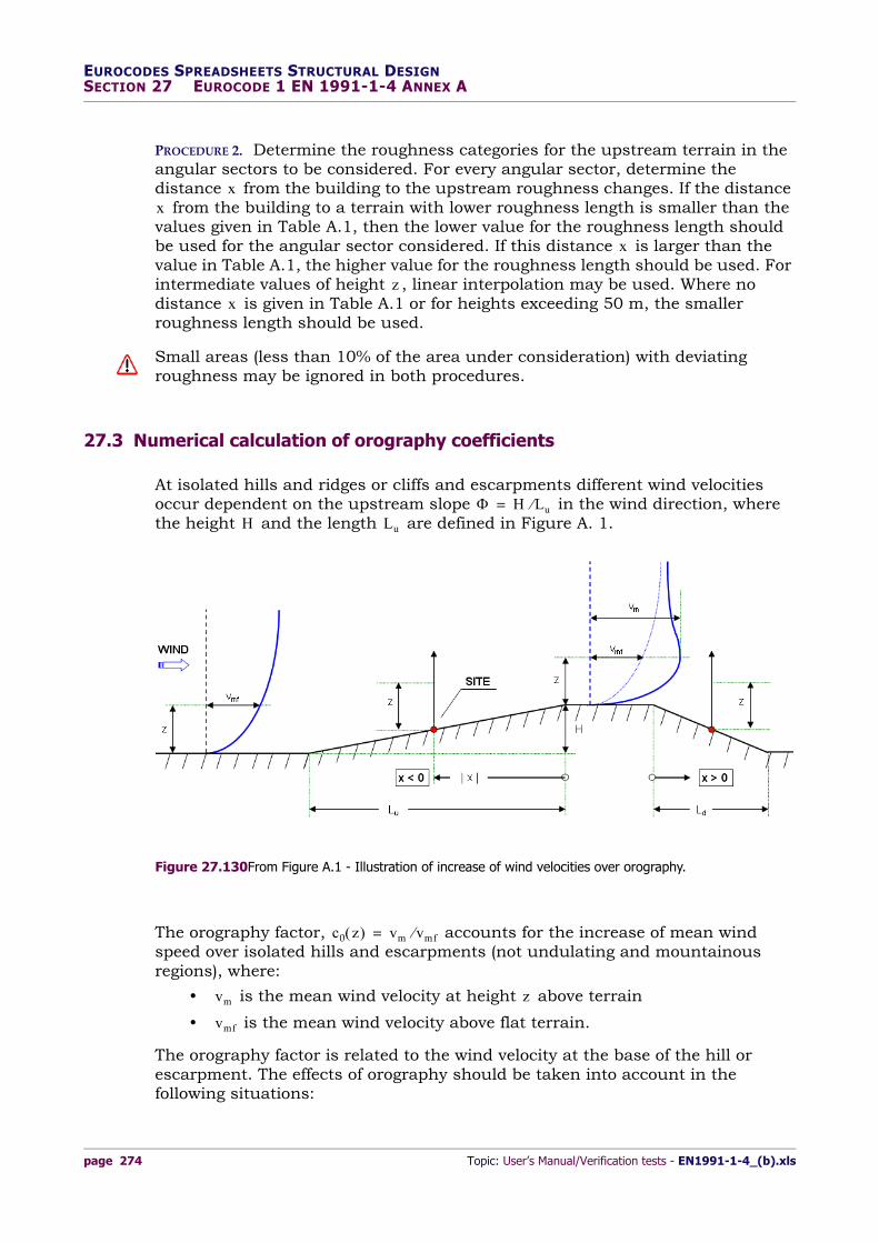
At isolated hills and ridges or cliffs and escarpments different wind velocities occur dependent on the upstream slope in the wind direction, where the height and the length are defined in Figure A. 1.
The orography factor, accounts for the increase of mean wind speed over isolated hills and escarpments (not undulating and mountainous regions), where:
• is the mean wind velocity at height above terrain
• is the mean wind velocity above flat terrain.
The orography factor is related to the wind velocity at the base of the hill or escarpment. The effects of orography should be taken into account in the following situations:
xx
x
zx
H Lu=H Lu
Figure 27.130From Figure A.1 - Illustration of increase of wind velocities over orography.
c0 z vm vmf=
vm z
vmf

Topic: User’s Manual/Verification tests - EN1991-1-4_(b).xls page 275
EUROCODES SPREADSHEETS STRUCTURAL DESIGNSECTION 27 EUROCODE 1 EN 1991-1-4 ANNEX A
a. for sites on upwind slopes of hills and ridges:
where and
b. for sites on downwind slopes of hills and ridges:
where and
where and
c. for sites on upwind slopes of cliffs and escarpments:
where and
d. for sites on downwind slopes of cliffs and escarpments:
where and
where and .
The orography factor is defined by:
for (Eq. 27‐107)
for (Eq. 27‐108)
for (Eq. 27‐109)
where:
• is the orographic location factor
• is the upwind slope in the wind direction
• is the actual length of the upwind slope in the wind direction
• is the effective length of the upwind slope: for shallow slope , for steep slope
• is the actual length of the downwind slope in the wind direction
• is the effective height of the feature
• is the horizontal distance of the site from the top of the crest
• is the vertical distance from the ground level of the site.
The following expressions may be used to compute the value of orographic location factor, :
a) upwind section for all orography (Figures A.2 and A.3):
1. for the range:
and (Eq. 27‐110)
take:
(Eq. 27‐111)
where:
0 05 0 3 x Lu 2
0 3 x Ld 2
0 3 x 1 6H
0 05 0 3 x Lu 2
0 3 x 1 5L e
0 3 x 5H
c0 1= 0 05
c0 1 2s += 0 05 0 3
c0 1 0 6s+= 0 3
s
H Lu
Lu
Le Le Lu=0 05 0 3 Le H 0 3= 0 3
Ld
H
x
z
✍s
1 5–xLu----- 0 0
zLe----- 2 0
s ABxLu-------
exp=

EUROCODES SPREADSHEETS STRUCTURAL DESIGN SECTION 27 EUROCODE 1 EN 1991-1-4 ANNEX A
page 276 Topic: User’s Manual/Verification tests - EN1991-1-4_(b).xls
(Eq. 27‐112)
and:
(Eq. 27‐113)
2. for the ranges:
or (Eq. 27‐114)
take .
b) downwind section for cliffs and escarpments (Figure A.2):
1. for the ranges:
and (Eq. 27‐115)
take:
(Eq. 27‐116)
where:
(Eq. 27‐117)
(Eq. 27‐118)
. (Eq. 27‐119)
2. for the range:
(Eq. 27‐120)
interpolate between values for (with in Eq.27-112) and .
3. when use the values for
A 0 1552zLe-----
4 0 8575 zLe-----
3– 1 8133 zLe-----
2 1 9115 zLe-----
1 0124+–+=
B 0 3542 zLe-----
2 1 0577 zLe-----
2 6456+–=
xLe----- 1 5– z
Le----- 2
s 0=
0 1xLe----- 3 5 0 1
zLe----- 2 0
s AxLe-----log
2 BxLe-----log
C++=
A 1 3420–zLe-----log
3 0 8222zLe-----log
2 0 4609zLe-----log
0 0791–+–=
B 1 0196–zLe-----log
3 0 8910zLe-----log
2 0 5343zLe-----log
0 1156–+–=
C 0 8030 zLe-----log
3 0 4236zLe-----log
2 0– 5738zLe-----log
0 1606++=
0xLe----- 0 1
x Le s A=x Le 0 1=
z Le 0 1 z Le 0 1=

Topic: User’s Manual/Verification tests - EN1991-1-4_(b).xls page 277
EUROCODES SPREADSHEETS STRUCTURAL DESIGNSECTION 27 EUROCODE 1 EN 1991-1-4 ANNEX A
4. for the ranges: or take the value .
c) downwind section for hills and ridges (Figure A.3):
1. for the ranges:
and (Eq. 27‐121)
take:
(Eq. 27‐122)
where:
(Eq. 27‐123)
(Eq. 27‐124)
2. for the ranges:
or take . (Eq. 27‐125)
27.4 Neighbouring structures
If a building is more than twice as high as the average height of the neighbouring structures then, as a first approximation, the design of any of those nearby structures may be based on the peak velocity pressure at height above ground. Let be the radius given by expressions (see Figure below):
if
if ,
then, we have:
for , (Eq. 27‐126)
for , (Eq. 27‐127)
for , (Eq. 27‐128)
x Le 3 5 z Le 2 0 s 0=
0xLd----- 2 0 0
zLe----- 2 0
s ABxLd------- exp=
A 0 1552zLe-----
4 0 8575 zLe-----
3– 1 8133 zLe-----
2 1 9115 zLe-----
1 0124+–+=
B 0 3056–zLe-----
2 1 0212zLe-----
1 7637–+=
xLd----- 2 0 z
Le----- 2 0 s 0=
have
znr
r hhigh= hhigh 2dl earg
r 2dl earg= hhigh 2dl earg
x r zn 0 5r=
r x 2r zn 0 5 r 12hlowr
-------------– x r– –=
x 2r zn hlow=

EUROCODES SPREADSHEETS STRUCTURAL DESIGN SECTION 27 EUROCODE 1 EN 1991-1-4 ANNEX A
page 278 Topic: User’s Manual/Verification tests - EN1991-1-4_(b).xls
where:
• is height of the tallest building
• , are the plan dimensions of the tallest building
• is the average height of the neighbouring structures
• is the height of the nearby structure
• is the distance from the tallest building (see or on figure below).
27.5 Displacement height
For buildings in terrain category IV, closely spaced buildings and other obstructions causes the wind to behave as if the ground level was raised to a displacement height, . Hence, the profile of peak velocity pressure over height may be lifted by a height .
hhigh
dsmall dl earg
have
hlow
x x1 x2
Figure 27.131From Figure A.4 - Influence of a high rise building, on two different nearby structures (1 and 2)
hdishdis
Figure 27.132Obstruction height and upwind spacing (the figure shows a particular case).

Topic: User’s Manual/Verification tests - EN1991-1-4_(b).xls page 279
EUROCODES SPREADSHEETS STRUCTURAL DESIGNSECTION 27 EUROCODE 1 EN 1991-1-4 ANNEX A
For range: , (Eq. 27‐129)
for range: , (Eq. 27‐130)
when take: . (Eq. 27‐131)
Note In the absence of more accurate information the obstruction height may be taken as have = 15 m for terrain category IV.
27.6 Verification tests
EN1991‐1‐4_(B).XLS. 6.73 MB. Created: 14 March 2013. Last/Rel.-date: 14 March 2013. Sheets:
— Splash
— Annex A.
EXAMPLE 27-CL‐ Transition between roughness categories 0, I, II, III and IV ‐ test1
Given: The transition between different roughness categories has to be considered for calculations. Roughness categories for the upstream terrain in the angular sector are considered from terrain “Category I” to terrain “Category III” and viceversa. Assume an height above ground equal to and a distance from the building to a terrain with lower roughness length equal to . Find which value for the roughness length should be used. Use the “Procedure 2”.
[Reference sheet: Annex A]‐[Cell‐Range: P9:R9‐P10:R10‐CommandButton].
Solution: From Table A.1:
for , entering the third column, we get (linear interpolation):
x 2have hdis min 0 8 have 0 6h; =
2have x 6have hdis min 1 2 have 0 2 x– 0 6h; =
x 6have hdis 0=
z 9 m=x 21 km=
Height z I to II I to III
5 m 0,50 km 5,00 km
7 m 1,00 km 10,00 km
10 m 2,00 km 20,00 km
15 m 5,00 km
20 m 12,00 km
30 m 20,00 km
50 m 50,00 km
Table 27.59 From Table A.1 - Distance x.
z 9 m=

EUROCODES SPREADSHEETS STRUCTURAL DESIGN SECTION 27 EUROCODE 1 EN 1991-1-4 ANNEX A
page 280 Topic: User’s Manual/Verification tests - EN1991-1-4_(b).xls
.
Then, we have: . Thus, the higher value for the roughness length should be used: (see Table 4.1, EN 1991-1-4).
20 00 10 00–10 7–
------------------------------------x 10 00–z 7 00–
------------------------ = 20 00 10 00–
10 7–------------------------------------ x 10 00–
9 7 00–----------------------- = x 16 67 m=
x 21 km 16 67 m=z0 0 3 m=
Figure 27.133PreCalculus Excel® form: procedure for a quick pre-calculation.
Figure 27.134PreCalculus Excel form: procedure for a quick pre-calculation.

Topic: User’s Manual/Verification tests - EN1991-1-4_(b).xls page 281
EUROCODES SPREADSHEETS STRUCTURAL DESIGNSECTION 27 EUROCODE 1 EN 1991-1-4 ANNEX A
From terrain category III to category III the standard has not recommended procedures:
example-end
the smoother terrain category might be applied.
EXAMPLE 27-CM‐ Transition between roughness categories 0, I, II, III and IV ‐ test1b
Given: Using the same assumptions of the previous example, find the roughness length to be used for calculations for and . Use the “Procedure 2”.
[Reference sheet: Annex A]‐[Cell‐Range: P9:R9‐P10:R10‐CommandButton].
Solution: As determined by the Standard (A.2(1)), where no distance is given in Table A.1 or for heights exceeding 50 m, the smaller roughness length should be used.
example-end
From Table 4.1 (“Terrain categories and terrain parameters“): .
EXAMPLE 27-CN‐ Transition between roughness categories 0, I, II, III and IV ‐ test1c
Given: From terrain category II to category III, find the roughness length to be used for and . Use the “Procedure 2”.
[Reference sheet: Annex A]‐[Cell‐Range: P9:R9‐P10:R10‐CommandButton].
z 60 m= x 21 km=
x
Figure 27.135PreCalculus Excel form: procedure for a quick pre-calculation.
z0 min 0 01 0 3; 0 01 m= =
z 25 m=x 8 km=

EUROCODES SPREADSHEETS STRUCTURAL DESIGN SECTION 27 EUROCODE 1 EN 1991-1-4 ANNEX A
page 282 Topic: User’s Manual/Verification tests - EN1991-1-4_(b).xls
Solution: For , entering Table A.1, we get (linear interpolation): .
Then, we have: .
example-end
Thus, the lower value for the roughness length should be used: .
EXAMPLE 27-CO‐ Transition between roughness categories 0, I, II, III and IV ‐ test1d
Given: A building is situated near a change of terrain roughness at a distance of from the smoother terrain category (Category 0). Find the terrain category in the upwind direction to be used for calculations. Use “Procedure 1”.
Height z II to III II to IV
5 m 0,30 km 2,00 km
7 m 0,50 km 3,50 km
10 m 1,00 km 7,00 km
15 m 3,00 km 20,00 km
20 m 7,00 km
30 m 10,00 km
50 m 30,00 km
Table 27.60 From Table A.1 - Distance x.
z 25 m=x 7 00 10 00+ 2 8 50 m= =
x 8 km 8 50 m=
Figure 27.136PreCalculus Excel form: procedure for a quick pre-calculation.
z0 0 05 m=
x 2500 m=

Topic: User’s Manual/Verification tests - EN1991-1-4_(b).xls page 283
EUROCODES SPREADSHEETS STRUCTURAL DESIGNSECTION 27 EUROCODE 1 EN 1991-1-4 ANNEX A
[Reference sheet: Annex A]‐[Cell‐Range: P9:R9‐P10:R10‐CommandButton].
Solution: As determined by the Standard (A.2(1)), if the structure is situated near a change of terrain roughness at a distance less than from the smoother category 0 the smoother terrain category in the upwind direction should be used.
We have . Therefore, the actual terrain category where the building is
example-end
situated should be used for calculations.
EXAMPLE 27-CP‐ Numerical calculation of orography coefficients ‐ test2
Given: Find the upstream slope, the orography location factor, the orography factor, and the type of slope for a site with:
– an actual length of the upwind slope in the wind direction:
– an actual length of the downwind slope in the wind direction:
– a vertical distance from the ground level of the site:
– an effective height of the feature:
– an horizontal distance of the site from the top of the crest: .
[Reference sheet: Annex A]‐[Cell‐Range: A1:N1‐A120:N120].
2 km
Figure 27.137PreCalculus Excel form: procedure for a quick pre-calculation.
x 2500 m 2 km=
Lu 250 m=
Ld 100 m=
z 10 m=
H 50 m=
x 160 m=

EUROCODES SPREADSHEETS STRUCTURAL DESIGN SECTION 27 EUROCODE 1 EN 1991-1-4 ANNEX A
page 284 Topic: User’s Manual/Verification tests - EN1991-1-4_(b).xls
Solution: Upstream slope in the wind direction: . From Table A.2 “Values of the effective length Le”:
orography factor for : . Effective length: . The orography factor, accounts for the increase of mean wind speed over isolated hills and escarpments (not undulating and mountainous regions). It is related to the wind velocity at the base of the hill or escarpment. The effects of orography should be taken into account in the following situations:
a) for sites on upwind slopes of hills and ridges:
– where and [Case Not Applicable]
b) for sites on downwind slopes of hills and ridges:
– where and [Case Applicable]
– where [Case Not Applicable] and
c) for sites on upwind slopes of cliffs and escarpments:
– where and [Case Not Applicable]
d) for sites on downwind slopes of cliffs and escarpments:
– where and [Case Applicable]
– where [Case Not Applicable] and .
a) Upwind section for all orography (see Figures A.2 and A.3):
In this case, considering , for the range and ,
we have: and . [Case Applicable]
Therefore, with , we get:
.
. Therefore, with , we get:
.
b) downwind section for cliffs and escarpments (Figure A.2):
In this case, considering , for the range and , we have: and . [Case Not
Applicable]
Type of slope ( = H/Lu)
Shallow : Steep :
Table 27.61 From Table A.2.
H Lu 50 250 0 20= = =
0 05 0 3 Le Lu= 0 3 Le H 0 3=
0 05 0 3 c0 1 2s += Le Lu 250 m= =co z vm vmf=
0 05 0 3 x 160 m Lu 2 125 m= =
0 3 x 160 m Ld 2 50 m= =
0 20 0 30= x 1 6H
0 3 x Lu 2 125 m=
0 3 x 160 m 1 5L e 375 m= =
0 3 x 5H
x 160 m–= 1 5– x Lu 0 0 z Le 2 0
1 5– 160– 250 0 0 10 250 2 0
z Le 0 04=
A 0 1552zLe-----
4 0 8575 zLe-----
3– 1 8133 zLe-----
2 1 9115 zLe-----
1 0124+–+=
A 0 1552 0 04 4 0 8575 0 04 3– 1 8133 0 04 2 1 9115 0 04 1 0124+–+=
A 3 977–10 548 8
7–10– 0 00290 0 07646 1 0124+–+ 0 9388= =
B 0 3542 zLe-----
2 1 0577 zLe-----
2 6456+– 0 3542 0 04 2 1 0577 0 04 2 6456+–= =
B 0 000567 0 04231 2 6456+– 2 6039= = x Lu 0 64–=
s A BxLu-----
exp 0 9388 2– 6039 0 64 exp 0 1773= = =
x + 160 m= 0 1 x Le 3 5 0 1 z Le 2 0 0 1 160 250 3 5 0 1 10 250 3 5

Topic: User’s Manual/Verification tests - EN1991-1-4_(b).xls page 285
EUROCODES SPREADSHEETS STRUCTURAL DESIGNSECTION 27 EUROCODE 1 EN 1991-1-4 ANNEX A
Therefore, with , we get:
.
.
.
Therefore, with , we get:
.
EXAMPLE 27-CQ‐ Numerical calculation of orography coefficients ‐ test2b
Given: Assume that it is valid the case “b) Downwind section for cliffs and escarpments” within the range: with and .
[Reference sheet: Annex A]‐[Cell‐Range: A127:N127‐A158:N158].
Solution: Referring to the calculations above, we find with :
; ;
(reference cells: U109; U112 and U115).
We get with :
.
Linear interpolation:
.
with for:
z Le 0 04=
A 1 3420–zLe-----log
3 0 8222zLe-----log
2 0 4609zLe-----log
0 0791–+–=
A 1 3420– 0 04 log 3 0 8222 0 04 log 2 0 4609 0 04 log 0 0791–+–=
A 3 66622 1 60677– 0 64431– 0 0791– 1 3360= =
B 1 0196–zLe-----log
3 0 8910zLe-----log
2 0 5343zLe-----log
0 1156–+–=
B 1 0196– 0 04 log 3 0 8910 0 04 log 2 0 5343 0 04 log 0 1156–+–=
B 2 78545 1 74122– 0 74692– 0 1156– 0 1817= =
C 0 8030 zLe-----log
3 0 4236zLe-----log
2 0– 5738zLe-----log
0 1606++=
C 0 8030 0 04 log 3 0 4236 0 04 log 2 0– 5738 0 04 log 0 1606++=
C 2 19372– 0 82781 0 80214 0 1606+ + + 0 4032–= =
x Le 160 250 0 64= =
s AxLe-----log
2 BxLe-----log
C++ 1 3360 0 64 log 2 0 1817 0 64 log 0 4032–+= =
s 0 05019 0 03522– 0 4032– 0 3882–= =
0 x Le 0 1 x Le 10 250 0 08= = z Le 10 250 0 04= =
x Le 0 1=
A x Le A 0 1 0 0202–= = B x Le B 0 1 0 5213–= =
C x Le C 0 1 0 3550= =
x Le 0 1=
s AxLe-----log
2 BxLe-----log
C++ 0 0202– 0 1 log 2 0 5213 0 1 log 0 3550+–= =
s 0 1 0 02– 0 5213 0 3550++ 0 856= =
s x Le s 0 08 0 9388 0 8561– 0 1 0 08– 0 1
----------------------------------------------------------------------------------- 0 8561+ 0 8726= = =
x Le 0=
s 0 A 0 1552zLe-----
4 0 8575 zLe-----
3– 1 8133 zLe-----
2 1 9115 zLe-----
1 0124+–+ 0 9388= = =

EUROCODES SPREADSHEETS STRUCTURAL DESIGN SECTION 27 EUROCODE 1 EN 1991-1-4 ANNEX A
page 286 Topic: User’s Manual/Verification tests - EN1991-1-4_(b).xls
example-end
(see previous example with ).
EXAMPLE 27-CR‐ Numerical calculation of orography coefficients ‐ test2c
Given: Find the orography location factor for “c) Downwind section for hills and ridges”. Let us assume the same assumptions in the previous example.
[Reference sheet: Annex A]‐[Cell‐Range: A162:N162‐A180:N180].
Solution: In this case, we are in the range: and . In particular, from the previous examples we have: and with
(see example 27‐CP on page 283).
.
We find:
.
In this case, the orography factor is given by:
example-end
.
EXAMPLE 27-CS‐ Neighbouring structures ‐ test3
Given: Find the height above ground at which the peak velocity pressure may be based on for structure influenced by a high rise building. Assume:
– height of the tallest building:
– plan dimensions of the tallest building: ;
– average height of the neighbouring structures:
– height of the nearby structure:
– distance “x” of the considered structure from the tallest building: .
z Le 0 04=
0 x Ld 2 0 0 z Le 2 0 x Ld 0 20= z Le 0 04=
A 0 1552zLe-----
4 0 8575 zLe-----
3– 1 8133 zLe-----
2 1 9115 zLe-----
1 0124+–+=
A 0 1552 0 04 4 0 8575 0 04 3– 1 8133 0 04 2 1 9115 0 04 1 0124+–+=
A 0 9388=
B 0 3056–zLe-----
2 1 0212zLe-----
1 7637–+=
B 0 3056– 0 04 2 1 0212 0 04 1 7637–+=
B 0 000489– 0 040848 1 7637–+ 1 7233–= =
s A BxLd-----
exp 0 9388 1 7233– 0 20 exp 0 665= = =
c0 z 1 2s + 1 2 0 665 0 20 + 1 266= = =
zn ze=
hhigh 60 m=
dl earg 20 m= dsmall 15 m=
have 20 m=
hlow 20 m=
x 10 m=

Topic: User’s Manual/Verification tests - EN1991-1-4_(b).xls page 287
EUROCODES SPREADSHEETS STRUCTURAL DESIGNSECTION 27 EUROCODE 1 EN 1991-1-4 ANNEX A
[Reference sheet: Annex A]‐[Cell‐Range: A254:N254‐A287:N287].
Solution: For we have: (radius).
As determined by the Standard, for : . In this case, increased wind velocities can’t be disregarded: . The considered building is more than twice as high as the average height of the neighbouring structures:
then, as a first approximation, the design of any of those nearby structures
example-end
may be based on the peak velocity pressure calculated at height .
EXAMPLE 27-CT‐ Displacement height ‐ test4
Given: Find the displacement height for:
– an average height of the neighbouring structures:
– an height of the building:
– a distance building from nearby structures: .
[Reference sheet: Annex A]‐[Cell‐Range: A312:N312‐A328:N328].
Solution: In this case, for the range , we get:
.
In the absence of more accurate information the obstruction height may be taken as
example-end
for terrain category IV.
27.7 References [Section 27]
EN 1991-1-4:2005/A1:2010. Eurocode 1: Actions on structures - Part 1-4: General actions - Wind actions. Brussels: CEN/TC 250 - Structural Eurocodes, April 2010.
EN 1991-1-4:2005. Eurocode 1: Actions on structures - Part 1-4: General actions - Wind actions. Brussels: CEN/TC 250 - Structural Eurocodes, March 2005 (DAV).
Manual for the design of building structures to Eurocode 1 and Basis of Structural Design April 2010. © 2010 The Institution of Structural Engineers.
Eurocode Load Combinations for Steel Structures. The British Constructional Steelwork Association Limited. BCSA Publication No. 53/10. December 2010.
hhigh 2dl earg 40 m= r 2dl earg 40 m= =
x r zn 0 5r 20 m= =hlow 0 5hhigh hlow 20 m=
have 20 m=
hhigh 2havezn 20 m=
hdishave 20 m=
h 35 m=
x 45 m=
2have x 6have hdis min 1 2 have 0 2 x– 0 6h; =
hdis min 1 2 20 0 2 45– 0 6 35; min 15 21; 15 m= = =
have 15 m=

(This page intentionally left blank)