Embed Size (px)
Citation preview

Section 2 Project Description
2. Project Description


Section 2 | Project Description
2-1Public Environmental Review/Draft Environmental Impact Statement
2 Project DescriptionThis chapter describes the offshore and onshore components of the proposed Outer Harbour Development in Port Hedland. It provides a brief description of construction methodology, operations and decommissioning, and provides the basis for the environmental impact assessment, and determination of the potential environmental and social impacts.
2.1 The ProjectThe proposed Outer Harbour Development will involve the construction and operation of landside and marine infrastructure for the handling and export of iron ore from BHP Billiton’s Iron Ore operations. This section describes the landside and marine components, as well as the supporting infrastructure and ore handling operations. An overview of the project’s location and layout is shown in Figure 1.2. The key characteristics of the project are outlined in Table 2.1.
Landside development includes:rail connections and spur from the ▸existing BHP Billiton Iron Ore Newman and Goldsworthy mainlines to proposed stockyards at Boodarie;rail loops at Boodarie; ▸stockyards and associated infrastructure ▸at Boodarie (e.g. car dumpers, stackers, reclaimers and lump rescreening plant);an infrastructure corridor (including ▸conveyors, access roadway and utilities) from the stockyards to the proposed marine jetty (offshore Finucane Island);a transfer station and conveyors on Finucane ▸Island; andconveyor connections to BHP Billiton Iron ▸Ore’s inner harbour berths.
Key marine structures include:an abutment (on Finucane Island), jetty and ▸wharf;mooring and associated mooring dolphins; ▸associated transfer stations, ore conveyors ▸and shiploaders;berth pockets, basins and channels; and ▸aids to navigation. ▸
This project description is based on the engineering investigation and design completed to date and incorporates alternatives and options which are still being considered. Alternatives will be evaluated as BHP Billiton Iron Ore continues with the detailed engineering and design process prior to construction. Alternatives that have been discounted are discussed in Section 3.
BHP Billiton Iron Ore’s investment in the development of the Outer Harbour proposal remains subject to external factors which are outside of its control, such as market conditions. Investment decisions will be made by BHP Billiton Iron Ore at each stage of the development subject to external factors at that time. This document has been prepared based on a estimated throughput capacity of 240 Mtpa for the Outer Harbour. This estimated capacity has been applied for the purpose of environmental impact assesment. Regulatory approvals are being sought for the construction and operation of landside and marine infrastructure to support BHP Billiton Iron Ore’s ongoing operations and Outer Harbour Development in Port Hedland. The basis for seeking regulatory approval for the complete development includes:
a large proportion of the proposed ▸disturbance resulting from land clearing (terrestrial environment) and capital dredging (marine environment) occurs in the early development stages; andthe opportunity for up front disclosure of the ▸cumulative impacts (e.g. potential dust and noise impacts) of the project.
The Outer Harbour Development is subject to BHP Billiton board approval, and all other necessary government and regulatory approvals.

Section 2 | Project Description
2-2 Public Environmental Review/Draft Environmental Impact Statement
Table 2.1 – Project Key Characteristics
Element DescriptionGeneral
Proponent BHP Billiton Iron Ore Pty Ltd.
Project Location Port Hedland, Western Australia.
Proposal Description Staged development of rail, iron ore handling, stockpiling and shiploading facilities at Port Hedland. Infrastructure includes a jetty, wharf and shipping channel offshore of Finucane Island with onshore infrastructure including ore transport (rail) and ore handling infrastructure (car dumpers, stockyards and conveyor system) and associated supporting infrastructure.
Construction Period Staged Construction, each stage nominally 2-3 years.
Marine Infrastructure
Export Capacity Marine Infrastructure nominal capacity of approximately 240 Mtpa.
Wharf Approximately 2 kilometres (km) in length.Eight berths and four shiploaders.
Jetty Approximately 4 km in length.
Shipping Channel Approximately 34 km in length (first 2 km located in State waters and remaining 32 km located in Commonwealth waters).
Dredge Material Volume: Approximately 54 million cubic metres (Mm3).Disposal: Three new offshore spoil grounds located in Commonwealth waters.
Landside Infrastructure
Capacity Landside Infrastructure nominal capacity of 300 Mtpa
Infrastructure Corridor From the Boodarie stockyards to Finucane Island and includes:access roadway and tracks;five conveyors up to 8 km in length; andpower, water and communication utilities (subject to separate environmental approvals);
Stockyards Staged Development: Each stage comprises ore stockpiles; a car dumper; 2 stackers; reclaimer; and lump rescreening plant.Two rescreened fines yard.
Rail Loop: Five rail loops, one for each car dumper.Connections to the existing rail infrastructure.Western Spur: approximately 32 km in length.
Footprint
Vegetation Clearing Total permanent area: Approximately 940 ha.
The disturbance envelope for landside infrastructure and construction activities for the Outer Harbour Development is approximately 4,270 ha and has been developed to allow for flexibility in locating project infrastructure during detailed engineering design. The disturbance envelope also encompasses partially disturbed land and includes existing infrastructure and decommissioned facilities such as BHP Billiton Iron Ore’s decommissioned hot briquetted iron (HBI) Plant at Boodarie.
The areas to be cleared within this disturbance envelope for permanent infrastructure and construction related activities/ facilities are smaller. It is proposed to permanently disturb approximately 940 ha (the infrastructure footprint) within the disturbance envelope.
Areas that are used for construction related activities/ facilities such as temporary contractor facilities, equipment laydown areas and borrow areas for fill (dependant on geotechnical investigation
outcomes), will be located within the disturbance envelope and will be progressively rehabilitated when they are no longer required to support construction activities.
2.2 Project ScheduleThe Outer Harbour Development is in study phase only and is therefore yet to be endorsed by the BHP Billiton Board.
For the preparation of this environmental impact assessment it was assumed that the commissioning date for each development stage would be sequential, allowing for the assessment of the cumulative construction impacts. It is anticipated that the construction will be completed over 4 stages with each stage taking normally 2-3 years to complete. The timing and composition of the stages will ultimatley be dependant on the market demand for iron ore as well as external and internal approvals and construction methodology.

Section 2 | Project Description
2-3Public Environmental Review/Draft Environmental Impact Statement
2.3 Land Use and TenureThere is a range of land uses in the local area surrounding the Outer Harbour Development, including:
existing port operations; ▸the town centre of Port Hedland; ▸the residential settlements at Port Hedland ▸and South Hedland;recreational features including beaches and ▸look out points;the industrial estate (including the ▸decommissioned HBI Plant) at Boodarie;the light industrial area of Wedgefield; and ▸pastoral leases. ▸
The land tenure and ownership details for the infrastructure of the Outer Harbour Development are outlined in Table 2.2.
Table 2.2 – Land Tenure and Ownership
Project Component Existing Ownership Existing Tenure Proposed changes to Tenure
Western Spur Railway Various land interests including Pippingara and Boodarie Pastoral Leases, crown land, reserves and crosses over a number of mining tenements and other easements held by third parties.
Existing tenure includes Special Lease 3116/3687 and J998591 Act.Various tenures held by third parties.
Miscellaneous Licences L 45/190, 194 and 198 under the Mining Act 1978 have been applied for to date.Additional licences will be applied for as required.
Boodarie Stockyards and residue storage impoundment (RSI) Facility
BHP Billiton Direct Reduced Iron Pty Ltd.
GPLs 45/62-211, 220-224, 235-256 Mining Proposal required to modify tenement conditions.
Infrastructure Corridor BHP Billiton Direct Reduced Iron Pty Ltd.
GPLs 45/62-211, 220-224, 235-256 Additional leases and/or licences will be applied for as necessary.
Goldsworthy Joint Venture Special Lease for rail J998591
Port Hedland Port Authority Part of Lot 370, 372 and 376
Reserve 50399 for Port Purposes Part of Lot 376
Finucane Island Transfer Station
Goldsworthy Joint Venture Special Leases GEI126342 (3116/5999) and J998595
Existing leases
Reserve 50399 for Port Purposes Part of Lot 376 New lease required over parts of this lot
Waters Port Hedland Port Authority Part of Lot 370 372 and 376 Lease from the Port Hedland Port Authority
Commonwealth of Australia Part of the waters vested in the Commonwealth in the adjacent offshore areas of Western Australia
Permits or licences issued by the Commonwealth Government
2.4 Landside InfrastructureIt is proposed that iron ore will be transported from inland Pilbara mines along the existing BHP Billiton Iron Ore Port Hedland-Newman Railway and proposed Western Spur Railway to stockyard facilities at Boodarie. Ore will be carried by overland conveyors to Finucane Island and transferred to the Inner Harbour facilities or to the Outer Harbour marine jetty/wharf (described in Section 2.5). The general arrangement of these landside structures is presented in Figure 2.1, with further details provided of the proposed stockyards and rail loops at Boodarie and transfer station on Finucane Island, in Figure 2.2 and Figure 2.3, respectively.
2.4.1 Railway RouteThe proposed Western Spur Railway route extends from the existing Port Hedland-Newman Railway mainline, at the 26 km chainage mark (Figure 2.1). The proposed alignment proceeds west from the Port Hedland-Newman Railway mainline for a distance of approximately 10 km, before tracking north, to the stockyards at Boodarie. The total length of new track is approximately 32 km.

Section 2 | Project Description
2-4 Public Environmental Review/Draft Environmental Impact Statement
The rail spur will require bridge crossings at:Fortescue Metals Group (FMG) Railway ▸located approximately 6 km west of the existing Port Hedland-Newman Railway mainline;Great Northern Highway intersection located ▸approximately 12 km west of the existing Port Hedland-Newman Railway mainline. It is proposed that the highway will be realigned and elevated above the rail; andBoodarie access road, where the road will be ▸realigned and elevated above the rail.
BHP Billiton Iron Ore has had preliminary discussions with relevant stakeholders, regarding the respective rail crossings and will continue to consult in parallel with further definition of the engineering design.
Communication and track signalling will also be constructed as part of the overall rail alignment. Specific locations of these components will be finalised as part of the detailed engineering design.
Rail Loops at BoodarieThe proposed Western Spur Railway will access the stockyards at Boodarie by means of new rail loops. The rail loops will also connect to the existing Goldsworthy Railway (Figure 2.1).
The overall configuration will comprise five parallel railway loops (one rail loop per car dumper) and their respective car dumpers as part of the stockyard arrangement. The marshalling yards, passing loops and maintenance areas required during operations will be located within the rail footprint or its immediate vicinity. Specific locations of these components will be finalised during the detailed design of the facilities. The proposed layout for the railway and loops is illustrated in Figure 2.1 and Figure 2.2.
2.4.2 Stockyards at BoodarieThe stockyard footprint is depicted in Figure 2.2, with a total of five car dumpers (Plate 2.1). The stockyard comprises the following components:
five car dumpers each with a nominal capacity ▸of approximately 60 Mtpa;ten rows of stockpiles; ▸ten stackers; ▸six bucket wheel reclaimers; ▸five lump re-screening plants; and ▸two re-screened fines stockyards. ▸
These components are supported by and integrated with conveyors, transfer stations, dust control measures, dust suppression cannons, and water supply and recovery systems. The Stockyards will have a nominal total capacity to support 300 Mtpa.
Plate 2.1 – Stockyards at Boodarie
Section 2 | Project Description
2-5Public Environmental Review/Draft Environmental Impact Statement
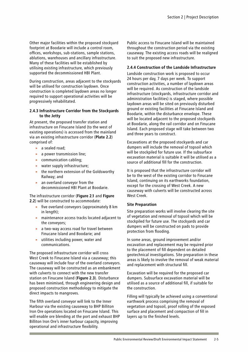
Other major facilities within the proposed stockyard footprint at Boodarie will include a control room, offices, workshops, sub-stations, sample stations, ablutions, warehouses and ancillary infrastructure. Many of these facilities will be established by utilising existing infrastructure, which previously supported the decommissioned HBI Plant.
During construction, areas adjacent to the stockyards will be utilised for construction laydown. Once construction is completed laydown areas no longer required to support operational activities will be progressively rehabilitated.
2.4.3 Infrastructure Corridor from the Stockyards to the Jetty
At present, the proposed transfer station and infrastructure on Finucane Island (to the west of existing operations) is accessed from the mainland via an existing infrastructure corridor (Plate 2.2) comprised of:
a sealed road; ▸a power transmission line; ▸communication cabling; ▸water supply infrastructure; ▸the northern extension of the Goldsworthy ▸Railway; andan overland conveyor from the ▸decommissioned HBI Plant at Boodarie.
The infrastructure corridor (Figure 2.1 and Figure 2.2) will be constructed to accommodate:
five overland conveyors (approximately 8 km ▸in length);maintenance access tracks located adjacent to ▸the conveyors;a two-way access road for travel between ▸Finucane Island and Boodarie; andutilities including power, water and ▸communications.
The proposed infrastructure corridor will cross West Creek to Finucane Island via a causeway; this causeway will include four of the overland conveyors. The causeway will be constructed as an embankment with culverts to connect with the new transfer station on Finucane Island (Figure 2.3). Disturbance has been minimised, through engineering design and proposed construction methodology to mitigate the direct impacts to mangroves.
The fifth overland conveyor will link to the Inner Harbour via the existing causeway to BHP Billiton Iron Ore operations located on Finucane Island. This will enable ore blending at the port and exhaust BHP Billiton Iron Ore’s inner harbour capacity, improving operational and infrastructure flexibility.
Public access to Finucane Island will be maintained throughout the construction period via the existing causeway. The existing access roads will be realigned to suit the proposed new infrastructure.
2.4.4 Construction of the Landside InfrastructureLandside construction work is proposed to occur 24 hours per day, 7 days per week. To support construction activities, a number of laydown areas will be required. As construction of the landside infrastructure (stockyards, infrastructure corridor and administration facilities) is staged, where possible laydown areas will be sited on previously disturbed ground or existing facilities at Finucane Island and Boodarie, within the disturbance envelope. These will be located adjacent to the proposed stockyards at Boodarie, along the rail corridor and on Finucane Island. Each proposed stage will take between two and three years to construct.
Excavations at the proposed stockyards and car dumpers will include the removal of topsoil which will be stockpiled for future use. If the subsurface excavation material is suitable it will be utilised as a source of additional fill for the construction.
It is proposed that the infrastructure corridor will be to the west of the existing corridor to Finucane Island, continuing on its earthworks foundation, except for the crossing of West Creek. A new causeway with culverts will be constructed across West Creek.
Site PreparationSite preparation works will involve clearing the site of vegetation and removal of topsoil which will be stockpiled for future use. The stockyards and car dumpers will be constructed on pads to provide protection from flooding.
In some areas, ground improvement and/or excavation and replacement may be required prior to the placement of fill dependent on detailed geotechnical investigations. Site preparation in these areas is likely to involve the removal of weak material and replacement with structural fill.
Excavation will be required for the proposed car dumpers. Subsurface excavation material will be utilised as a source of additional fill, if suitable for the construction.
Filling will typically be achieved using a conventional earthwork process comprising the removal of vegetation and topsoil, proof rolling of the exposed surface and placement and compaction of fill in layers up to the finished levels.

Section 2 | Project Description
2-6 Public Environmental Review/Draft Environmental Impact Statement
Onshore fill material will be sourced from on-site borrow pits or from a third-party quarry if suitable on-site borrow is not available. Borrow areas are discussed in more detail in Section 2.6.3.
PilingPiling activities may be required for all major equipment and structures such as the transfer station on Finucane Island, culverts across West Creek (conveyor corridor), lump rescreening plant and car dumpers at Boodarie. This will be determined following detailed geotechnical investigations.
Piling activities associated with marine works are described in Section 2.5.2.
DewateringDewatering of up to 8 mega litres (ML) per day for a period of approximately 9 to 12 months is likely to be required during excavation and construction activities for each car dumper (located at Boodarie). Dewatering is only required to support construction of the car dumpers. Appropriate disposal or reuse options for this water will be implemented depending on the quality and volume of water removed. If the quality of the water is appropriate, it will be used for dust suppression and other construction activities during construction works. Where the water quality or volume does not allow for onsite use, it will be disposed, discharged in accordance with guidelines, to the north of Boodarie, into Salmon Creek (Figure 2.2).
Plate 2.2 – Indicative Cross Section of the Infrastructure Corridor
Plate 2.3 – Indicative Cross Section of the West Creek Causeway

Section 2 | Project Description
2-7Public Environmental Review/Draft Environmental Impact Statement
Infrastructure CorridorThe material currently stored in Dredged Material Management Area A (DMMA A) (Figure 2.2) comprises fine sediments resulting from the onshore disposal and dewatering of dredged spoil associated with BHP Billiton Iron Ore’s approved Port Hedland Finucane Island Dredging project. This material has been tested for contaminants and found to be suitable for land disposal under relevant guidelines. Some of this material requires removal and will be replaced with engineering fill along the eastern side of DMMA A prior to construction of the infrastructure corridor. The material will be removed and relocated to an alternative storage location, or if suitable, will be used for fill.
West Creek CrossingA new causeway with culverts will be constructed across West Creek (Plate 2.3). The culvert sizing and distribution will be designed to minimise change in tidal flows and minimise the potential impact on the intertidal habitat (as detailed in Section 10). It is envisaged that construction of the crossing will occur end-to-end to minimise the construction footprint. The construction corridor will therefore be the width of the causeway.
Rail Line and LoopsThe rail spur will traverse relatively flat terrain and will be constructed above the predicted flood event levels and on embankments (Plate 2.4). The railway embankment will be constructed from borrow material sourced from borrow pits and third party quarries.
The rail loop embankment will include provision for drainage so that water accumulating within the loop from direct rainfall can be discharged after settlement into established drainage lines to the east and west of the rail loop.
Culverts will be incorporated along the rail line, allowing for cross-over of creeks and to minimise potential impacts from flooding. Culverts will typically be sized to 1:100 year flooding events.
Two bridges are proposed to be constructed:a bridge to cross over the FMG Railway; and ▸a bridge for the Great Northern Highway to cross ▸over the proposed rail (to be built in conjunction with Main Roads, Western Australia).
Following geotechnical site investigations, detailed engineering design will be undertaken to determine the final location of the Western Spur rail and loops. An indicative location has been inferred for this impact assessment. During engineering design, sensitive habitat areas and areas requiring avoidance will be taken into account.
Plate 2.4 – Proposed Western Spur and Rail Loops

Section 2 | Project Description
2-8 Public Environmental Review/Draft Environmental Impact Statement
2.5 Marine InfrastructureThis section considers the offshore marine infrastructure including the linkage of the transfer station on Finucane Island to the proposed wharf and shiploading facilities, and the dredging activities required to enable ship arrival and departure (Plate 2.5).
2.5.1 New Dredged Channel, Wharf and JettyThe proposed marine infrastructure for the new offshore loading facility will be constructed from Finucane Island. It will extend offshore in a northerly direction with a new jetty approximately 4 km in length and wharf 2 km in length to be constructed adjacent to the existing Inner Harbour shipping channel (Figure 2.4).
Plate 2.5 – Jetty/Wharf Structure
Plate 2.6 – Jetty Structure

!
26kmChainage Mark
Western Spur Railway
Car Dumpers
Boodarie Rail Loop
Jetty
AccessRoads
Goldsworthy Rail Loop
Stockyards
Boodarie RSI
Infrastructure Corridor
FINUCANE ISLAND
PORT HEDLAND
Transfer Station
Decommissioned HBI Plant
655000 660000 665000 670000
7735
000
7735
000
7740
000
7740
000
7745
000
7745
000
7750
000
7750
000
7755
000
7755
000
LegendPrincipal Road
Proposed Car Dumper
Proposed Jetty
Proposed Wharf
Proposed Goldsworthy Rail Loop
Proposed Western Spur Railway
Existing Railway
Disturbance Envelope
Proposed Infrastructure Corridor
Proposed Stockyards0 1 2
kilometres
°
Datum: GDA94Map Grid: MGA94 Zone 50
Source:Orthorectified Aerial Photograph: 08/06/2010 (BHPBIO)Topography: Geoscience Australia, GEODATA Topo 250K V3 (Copyright Commonwealth of Australia, 2006)
003\g004_WV05024_Rev0
!(
!(
!(
Indian Ocean
PERTH
NEWMAN
PORT HEDLAND
Figure 2.1 Proposed Landside Infrastructure Layout
GR
EAT
NO
RTH
ERN
HIG
HW
AY
Goldsworthy Railway
New
man
toPo
rtH
edla
ndR
ailw
ay
FMG
Railw
ay
1:100,000Scale at A4:
Final design drawing files will be forwarded to the relevantGovernment authorities on finalisation and completion.
This figure is an indicative representation of the current designof the Outer Harbour Development.Changes may be necessary as the engineering designprogresses to ensure it is efficient, practical and within landdisturbance requirements at the time of construction.

!5
Goldsworthy Railway
Infrastructure CorridorStockyards
Boodarie Rail Loop
Car Dumpers
FMGRailway
Boodarie RSI
Decommissioned HBI Plant
Salmon Creek
Goldsworthy Rail Loop
Western Spur Railway
658000 660000 662000
7742
000
7742
000
7744
000
7744
000
7746
000
7746
000
7748
000
7748
000
7750
000
7750
000
003\g005_WV05024_Rev0
Legend
!5 Dewatering Discharge Point
Dredged Material Management Area A
Proposed Goldsworthy Rail Loop
Proposed Western Spur Railway
Disturbance Envelope
Proposed Infrastructure Corridor
Proposed Stockyards
Proposed Car Dumper
Proposed Jetty
Proposed Wharf
Existing RailwaySource:Orthorectified Aerial Photograph: 23/06/2009 (BHPBIO)Topography: GEODATA Topo 250K V3 © Commonwealth of Australia (GA), 2006
Datum: GDA94Map Grid: MGA94 Zone 50
0 400 800
metres
°
!(
Indian Ocean
PORT HEDLAND
Figure 2.2 Proposed Stockyards, Rail Loop and Infrastructure Corridor
Scale = 1:40,000 at A4
Existing Dredged MaterialManagement Area A
Final design drawing files will be forwarded to the relevantGovernment authorities on finalisation and completion.
This figure is an indicative representation of the current design ofthe Outer Harbour Development.Changes may be necessary as the engineering designprogresses to ensure it is efficient, practical and within landdisturbance requirements at the time of construction.
Salmon Creek Discharge Point

Jetty
Conveyors
FINUCANE ISLAND
Abutment
Transfer Station
West Creek
662000 663000
7753
000
7753
000
7754
000
7754
000
7755
000
7755
000
LegendProposed Jetty
Proposed Infrastructure Corridor
Disturbance Envelope
0 100 200 300 400
metres
°
Datum: GDA94Map Grid: MGA94 Zone 50
Source:Orthorectified Aerial Photograph: 08/06/2009 (BHPBIO)Topography: GEODATA Topo 250K V3 © Commonwealth of Australia (GA), 2006
003\g006_WV05024_Rev0
Indian Ocean
PORT HEDLAND
1:10,000Scale =
Figure 2.3 Proposed Layout for Crossing, Conveyors and Transfer Station
at A4
Final design drawing files will be forwarded to the relevantGovernment authorities on finalisation and completion.
This figure is an indicative representation of the current design ofthe Outer Harbour Development.Changes may be necessary as the engineering designprogresses to ensure it is efficient, practical and within landdisturbance requirements at the time of construction.

Section 2 | Project Description
2-12 Public Environmental Review/Draft Environmental Impact Statement
The new iron ore marine loading facility will be capable of berthing and loading 250,000 dead weight tonnes (DWT) vessels with a design provision for 320,000 DWT vessels to berth and load in the future.
The key components of the offshore marine infrastructure will comprise the following:
an access jetty structure, including abutment ▸works;a deck for the transfer station where the jetty ▸meets the wharf;a wharf structure; ▸berthing and mooring dolphins; ▸ship access gangways and conveyor cross- ▸overs and cross-unders;aids to navigation; ▸a ship arrestor barrier structure; and ▸berth pockets, departure basins, swing basins, ▸link channels, new departure channel and tug access channel.
Access JettyA steel piled jetty of approximately 4 km in length is proposed to be constructed from Finucane Island to the wharf. The jetty will support four conveyors, maintenance services and a two lane roadway for vehicle access to the wharf.
The jetty conveyors will be constructed to transfer ore from the transfer station on Finucane Island to the transfer deck, then onto the wharf conveyors and into the shiploaders.
The passage of recreational water craft under the elevated jetty trestle will be permitted at controlled locations, for the purposes of safety (Plate 2.6).
Transfer DeckThe proposed transfer deck will be located at the end of the jetty and will connect to the wharf structure (Plate 2.7; Figure 2.4). The transfer deck will provide services and support facilities for construction, operational and maintenance personnel.
Wharf StructureThe proposed wharf structure and associated berthing and mooring dolphins will be located approximately 4 km north of Finucane Island. The wharf will be approximately 2 km in length and will be designed to accommodate:
shiploaders and associated rail system; ▸access roadway and walkways; ▸maintenance bays; ▸conveyor systems; ▸cyclone tie down facilities, and ▸support services (including amenities, offices ▸etc).
Plate 2.7 – Wharf and Transfer Deck

Section 2 | Project Description
2-13Public Environmental Review/Draft Environmental Impact Statement
Each stage of wharf development consists of two berths (Plate 2.7). The proposed construction staging of the eight berths is shown in Figure 2.5.
ShiploadersOne shiploader (for slewing, luffing and long travel) will be installed for each construction stage, totalling four shiploaders for the proposed Outer Harbour Development at full capacity. The ore will be delivered to the shiploaders via four conveyors (one per shiploader) located along the jetty and wharf.
Aids to NavigationAids to navigation will include new channel markers, departure leads and marker buoys for the new departure channel, departure link channel, crossover link channel, tug access channel, berth pockets, swing basins and departure basins. These aids to navigation will be provided in accordance with the requirements of the Port Hedland Port Authority (PHPA), the International Association of Lighthouse Authorities (IALA) and the International Maritime Organisation (IMO).
Berthing and Mooring DolphinsBerthing and mooring dolphins will be provided on both the east and west sides of the wharf and will be used for mooring and breasting the range of ships anticipated.
2.5.2 Construction of the Marine InfrastructurePlant and equipment required for the construction of the jetty and wharf structure will include multiple numbers of the equipment detailed in Table 2.3.
Wharf StructureTypically the wharf structure will be constructed by driving piles from jack up barges and placing a deck or similar on top of the piles.
It is anticipated that the wharf will be constructed in stages each nominally taking 2 years to construct. Each stage will include 2 berths and a shiploader to complete the facility with a total of eight berths operating with four conveyors and four shiploaders. The sequential implementation will allow exporting capacity to be incrementally brought on line.
Access JettyThe access jetty will be typically constructed using two methods of construction, one for the inner shallow area and the second for the outer deeper area.
The inner area will be constructed using an advancing truss system for driving piles, and advancing the jetty superstructure. The outer area will be constructed by driving piles from jack up barges and placing a deck or similar on top of the piles.
Table 2.3 – Marine Construction Equipment
Equipment Proposed UseJack-up barges (JUB) Pile installation, drilling operations, heavy lifting operations, transport of piles, assistance works and
supply of truss modules
Advancing Truss System (ATS) Pile installation, superstructure installation along the jetty
Heavy lift vessel/s Supply and installation of transfer deck, wharf and dolphin modulesSupply and delivery of access jetty roadway and conveyor truss modules
Crawler crane on JUB Installation of truss modules, piles, drill rig, piling hammers, assistance works
Crane on ATS Pile installation, break and grab operations, superstructure installation
Crawler cranes Loading of trusses and piles at the jetty abutment, lay down areas and load out facilitiesGeneral support at lay-down and workshop areas
Hydraulic piling hammers and power packs
Piling operations
RCD-Rig and power pack, drill tubes, pumps
Drilling operations
Crew boats Crew transfer
Tugs Tow of barges and JUB’s
Multi-cats Assisting tow of barges and JUB’s, positioning of anchors
Flattop barges Transport of piles during good weather and general support
Assorted prime mover trucks, trailers and other associated transport equipment
Onshore pile transportation
Dredgers Dredging and spoil disposal

I N D I A N O C E A N
PORT HEDLAND
Transfer Deck
Tug Access Channel
Berth Pockets and Swing Basins
Crossover Channel
Wharf and Berths
Link Channel
Departure Channel
Transfer Station
Abutment
Jetty
Existing Shipping Channel
Infrastructure Corridor FINUCANEISLAND
656000 658000 660000 662000 664000 666000
7752
000
7752
000
7754
000
7754
000
7756
000
7756
000
7758
000
7758
000
7760
000
7760
000
7762
000
7762
000
7764
000
7764
000
7766
000
7766
000
LegendStage 1 Berths
Stage 2 Berths
Stage 3 Berths
Stage 4 Berths
Proposed Infrastructure Corridor
Proposed Jetty
Existing Railway
Disturbance Envelope
Proposed Departure Channel
Proposed Berth Pockets and Swing Basins
Proposed Link Channel
Proposed Crossover Channel
Existing Shipping Channel
Proposed Tug Access ChannelState/CommonwealthJurisdiction Boundary
Source:Orthorectified Aerial Photograph:06/06/2010 (BHPBIO)Australian Maritime Boundaries (AMB) © Commonwealth of Australia (GA), 2006Topography: GEODATA Topo 250K V3 © Commonwealth of Australia (GA), 2006
003\g007_WV05024_Rev0
!(
!(
!(
Indian Ocean
PERTH
NEWMAN
PORT HEDLAND
Figure 2.4 Proposed Marine Infrastructure Layout
West Creek
Salm
onC
reek
0 0.5 1
kilometres
°
Datum: GDA94Map Grid: MGA94 Zone 50
1:65,000Scale = at A4
Limit of aerial photography data
Final design drawing files will be forwarded to the relevantGovernment authorities on finalisation and completion.
This figure is an indicative representation of the current designof the Outer Harbour Development.Changes may be necessary as the engineering designprogresses to ensure it is efficient, practical and within landdisturbance requirements at the time of construction.

003\
g008
_WV
0502
4_R
ev0
Lege
nd Stag
e 1
Ber
ths
Stag
e 2
Ber
ths
Stag
e 3
Ber
ths
Stag
e 4
Ber
ths
Sour
ce:
Orth
orec
tifie
d A
eria
l Pho
togr
aph:
15
/06/
2007
(BH
PB
IO)
Topo
grap
hy: G
eosc
ienc
e A
ustra
lia, G
EOD
ATA
To
po 2
50K
V3
Cha
nnel
: Nav
y H
ydro
grap
her (
Aus
0074
0)St
agin
g: 1
210-
S-1
2002
19/
11/2
008
(FA
ST)
Dat
um: G
DA
94M
ap G
rid: M
GA
94 Z
one
50
010
020
0
met
res°
!(
Indi
an
O
cean
POR
T H
ED
LAN
D
Figu
re 2
.5 S
tagi
ng o
f Wha
rfs a
nd B
erth
s
Scal
e =
1:9,
000
New
Shi
ploa
der N
o.12
Shi
ploa
der N
o. 1
1S
hipl
oade
r No.
9
BER
TH 1
E
BER
TH 3
E
BER
TH 4
E
BER
TH 4
WB
ERTH
3W
BER
TH 2
WB
ERTH
1W
BER
TH 1
E
BER
TH 2
E
BER
TH 3
E
BER
TH 3
WB
ERTH
2W
BER
TH 1
W
BER
TH 1
E
BER
TH 2
E
BER
TH 1
W
BER
TH 1
E
BER
TH 2
ES
hipl
oade
r No.
10
Shi
ploa
der N
o. 9
New
Shi
ploa
der N
o.11
New
Shi
ploa
der N
o.10
New
Shi
ploa
der N
o. 9
BER
TH 2
W
BER
TH 2
E
Shi
ploa
der N
o.10
STA
GE
1
STA
GE
2
STA
GE
3
STA
GE
4
at A
4
Shi
ploa
der N
o. 9
Final
desig
n dr
awing
file
s wi
ll be
for
ward
ed t
o the
rele
vant
Gove
rnme
nt au
thoriti
es o
n fina
lisati
on a
nd co
mplet
ion.
This
figur
e is
an in
dicati
ve re
pres
entat
ion o
f the
cur
rent
desig
nof
the O
uter
Har
bour
Dev
elopm
ent.
Chan
ges
may
be
nece
ssar
y as
the
en
ginee
ring
desig
npr
ogre
sses
to e
nsur
e it
is eff
icien
t, pr
actic
al an
d wi
thin
land
distur
banc
e req
uirem
ents
at the
time o
f con
struc
tion.

Section 2 | Project Description
2-16 Public Environmental Review/Draft Environmental Impact Statement
Construction of marine infrastructure will maximise the use of precast or prefabricated components. Laydown areas on Finucane Island and at Boodarie will be utilised to temporarily store material, components and equipment for the construction of the marine structures. Some equipment and components will arrive by heavy lift ship and be installed directly onto the substructure. Other equipment and components may be stored on the structure before erection.
PilingMarine infrastructure (including jetty, transfer platform, wharf, dolphins, navigation aids and ship arrestor) will require a total of approximately 1840 piles to be driven for the development:
Stage 1 – approximately 930 piles; ▸Stage 2 – approximately 70 piles; ▸Stage 3 – approximately 420 piles; and ▸Stage 4 – approximately 420 piles. ▸
The pile installation method may require some drilling, dependent on the stratigraphy.
Construction work is proposed 24 hours per day, 7 days per week, with favourable conditions. Supporting activities associated with piling (e.g. site preparation) will be undertaken 24 hours per day, 7 days per week. However, physical piling activities are proposed to be conducted 12 hours per day (7am to 7pm), 13 days per fortnight. Occasionally for safety reasons, there will be the requirement to continue piling activities up to 10 pm to accommodate the completion of a pile.
Construction TrafficConstruction is divided into two main activities, the dredging programme and construction of marine structures, with each activity having a different fleet mix and methodology (Table 2.4)

Section 2 | Project Description
2-17Public Environmental Review/Draft Environmental Impact Statement
Table 2.4 – Construction Vessel Movements
Type of vesselMaximum number in use
Maximum speed (knots)
Pathway Frequency and duration
Dredging
Trailing Suction Hopper Dredger
2 10 The trailer dredger will generally work between the areas to be dredged and the spoil grounds 2, 3, 7 and 9.Approx 80% of the dredging is in the berth pocket, arrival and departure ground locations, and very low percentage is in the outer channel.The dredger will load dredge material at the dredge site (while it is stationary / slow moving) then travel to the spoil ground at normal speed and then dump the spoil and return to the dredging site for its next load.
Dredging (Construction)Stage 1: 2 yearsStage 2 : 2 yearsStage 3 : 7 months
Cutter dredger (non-self propelled)
1 4 (towed) The cutter dredger will almost entirely be positioned in the area of berth pockets, arrival and departure basins and will generally be stationary. The cutter typically positions itself, dredges material, and then moves forward to a new position.
Cutter dredger (self propelled)
1 7-9 Same as non-self propelled.
Tug 2 Variable General provision of tug and towages services to dredging fleet, positioning of dredgers, moorings, anchors etc.
Multi-cat 2 5-7 General support to dredging fleet, supply and delivery of material.
Crew boat 2 12-20 Crew transfer between vessel at start and end of shift.
Survey boat 1 12-15 Provide survey services to ensure dredgers are working in correct location and are dredging to the required scope, measure volumes dredged and spoil ground levels.
Sweep boat and barge
2 Variable General support to dredging fleet, supply, delivery and storage of material, mooring lines, anchors etc.
Marine Facilities Construction
Jack-up barge (JUB)
4 Variable JUB will typically be positioned at the site of construction and will generally be used for pile driving and drilling. These vessels will typically be stationary while they install piles, and then move by lugs to the next location. In the case of the jetty, they will progressively move along the structure at approximately 40 m intervals
Nominally 2-3 years per stage, for all 4 stages.
Tug 4 Variable These vessels will generally provide support services to the JUB’s and heavy lift vessels, including tug and towage, supply of material and people, moving of anchors and mooring lines, crew transfer etc. It is envisaged that these vessels will travel to and from the inner harbour at the start and end of each shift.
Material barge 7 Variable
Working platforms/ pontoons
3 Variable
Safety boat 2 Variable
Work boat 2 Variable
Crew boat 7 12 – 20
Multi-cat 2 5 – 7
Sheer leg 1 Variable For 16 months during construction
Floating batching plant
2 Variable This vessel will travel between the inner harbour and the construction site, supplying concrete and other material, typically once per shift.
Nominally 2-3 years per stage
Heavy lift vessels 2 Variable Restricted to existing channel, inner harbour and wharf footprint.
Nominally 2-3 years per stage, for all 4 stages.

Section 2 | Project Description
2-18 Public Environmental Review/Draft Environmental Impact Statement
2.5.3 Dredging and Spoil Disposal ProgramDredging is required to enable vessel access to the wharf facility and for loaded vessels to depart to deep water.
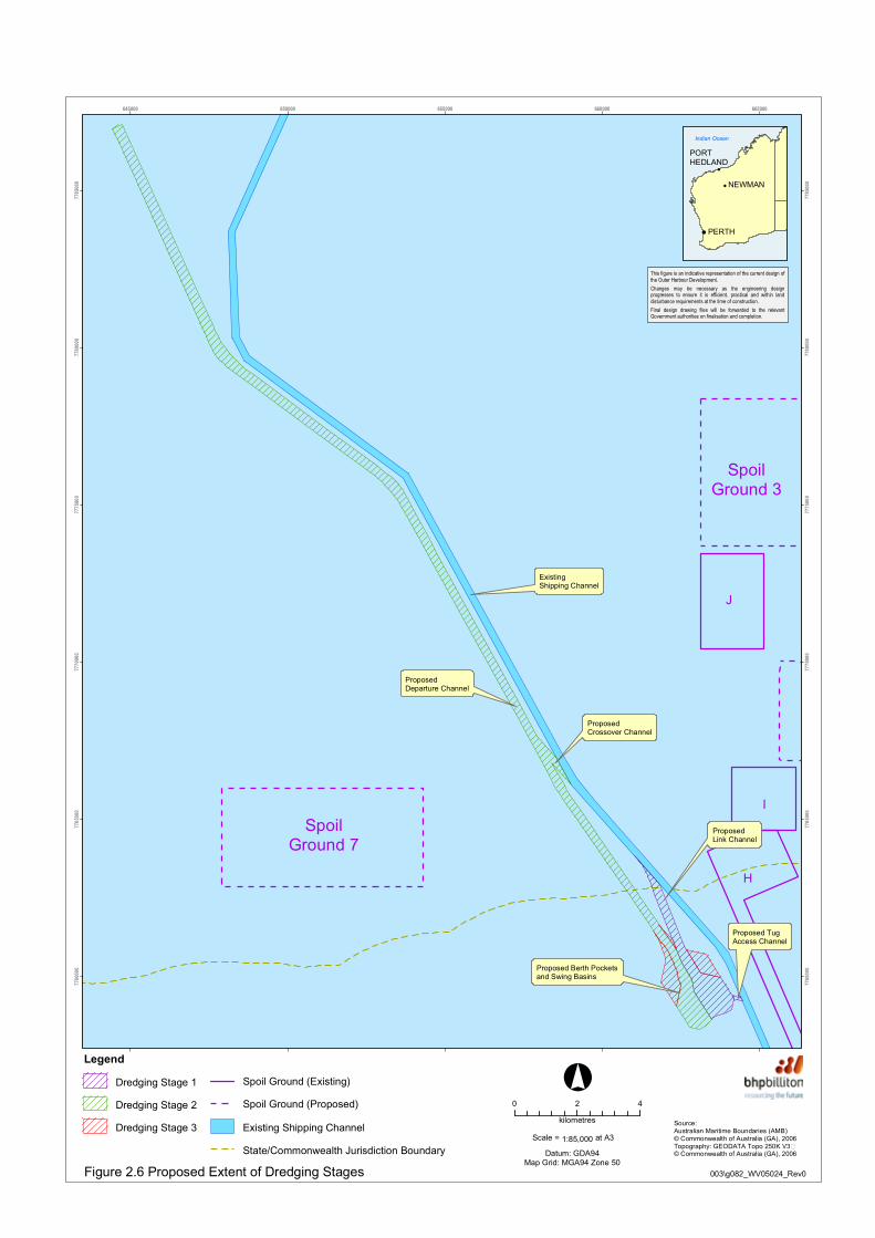
Dredging operations will create new berth pockets, swing basins, departure basins, a departure link channel to the existing shipping channel, a departure channel, a crossover link channel and tug access channel from the existing channel into the berth pockets. The extent of the proposed dredging areas is shown in Figure 2.6.
The proposed departure channel will be approximately 34 km in length and is aligned approximately parallel to the existing and previously dredged Port Hedland shipping channel, deviating to the north-west from the existing channel at the outer end. The departure channel varies in width from 260 m (at the berth pockets) up to 330 m wide (at the end of the channel) determined by vessel speeds, under keel and bank clearances, and has been designed in accordance with PIANC (the World Association for Waterbourne Transport Infrastructure) guidelines for navigation channels. The departure channel is designed for a single lane of vessels departing, with no provision for passing. The departure channel alignment has been selected in order to:
avoid charted shallow water and provide a ▸safer route for departing vessels;minimise disturbance to potentially sensitive ▸marine habitat;maximise synergies with existing shipping ▸infrastructure;minimise the travel distance to deep water; ▸andconstrain proposed disturbance and activities ▸as close to existing developed areas as possible.
The layout and widths of channels, berth pockets, swing and departure basins have been designed for the proposed vessel types in accordance with international standards (refer Table 1.4). The berth pocket is dredged to allow for the deepest draft vessel to be fully loaded at any tidal or sea state conditions, allowing for siltation, vessel list and vessel trim (up to – 21.9m RL). The departure basin at the beginning of the departure channel is dredged to allow for safe tidal navigation for a spectrum of vessels, and flares to allow for interaction effects as vessels pass each other. The swing basin is dredged to a shallower depth (-10.4m RL), with dredging minimised to enable bringing in a vessel safely in an acceptable tidal window. Dredging and design aim to minimise the possibility of short loading times
and demurrage due to inaccessibility. The swing and departure basins, berth pockets and up to 3 km of the new departure channel will be located in State waters, with the remainder of the departure channel being in Commonwealth waters.
Dredging ProgramThe total volume of dredged material is estimated to be approximately 54 Mm3 (inclusive of any over-dredging) for the Outer Harbour Development. A range of material types are present within the proposed dredging footprint, requiring the use of a trailing suction hopper dredger (TSHD) for unconsolidated materials. Harder materials will initially require cutting and/or crushing using a cutter suction dredger (CSD) with the crushed material being left on the seabed for subsequent removal with a TSHD.
Typically dredging will start with a TSHD removing the top layers of unconsolidated materials. Once a sufficiently large area has been cleared down to the hard layer, a CSD will then be deployed to crush the material and deposit the crushed rock material back onto the seabed immediately behind the cutter head using its submerged ladder pump, for subsequent removal by the TSHD.
The sequence of cutting and crushing per layer in a certain area and subsequent removal by a TSHD will be repeated until the design depth is reached. In areas where the surface is of harder material, the CSD will be required as the first pass to cut and crush material before the TSHD is deployed. Plate 2.8 illustrates the complex stratigraphy within the proposed wharf area.
In the shallow areas irrespective of the material types it may be necessary to first create sufficient water depth for the TSHD by using the CSD. In this case the dredged material will be stockpiled into deeper water within the dredge footprint away from the CSD using a floating pipeline and a spreader barge discharging at near seabed level, from where it will subsequently be removed by a TSHD.
Some disturbance of the seabed, beyond the dredging footprint may occur during the dredging works, due to the placement of anchors or CSD spuds. This disturbance will be relatively minor and typically the CSD’s side anchors may by placed up to a distance of 50 m to 100 m beyond the dredging footprint, as shown in Figure 2.6. In locations where the hardest of the materials present is to be dredged by the cutter dredger, the side anchors may have to be placed up to 150 m beyond the top of the dredged batters. TSHDs will operate within the dredging footprint.

Section 2 | Project Description
2-19Public Environmental Review/Draft Environmental Impact Statement
Based on the geotechnical studies completed to date there have been no areas identified in the dredge footprint that would necessitate marine blasting operations for material extraction. Offshore geotechnical investigations will be undertaken to further characterise the dredged material, confirm the proposed dredging techniques and optimise engineering design. The results from this work will be finalised in June 2011 and feed into the dredging and engineering design programmes. Once the revised dredging programme has been completed BHP Billiton Iron Ore will re-model the dredging impacts.
Dredging operations will be conducted on a 24 hours per day, 7 days per week basis. It is proposed that dredging will occur in a staged manner (as shown in Figure 2.6), as follows:1. Dredging of berth pockets, eastern swing and
departure basins, a tug access channel and a link channel to the existing channel to provide two loading berths.
2. Dredging of the western swing and departure basins to provide two additional loading berths. This stage also includes the dredging works for the new 34 km departure channel and the crossover link channel.
3. Dredging for the extension of the wharf with additional berth pockets and the swing and departure basins to accommodate another four loading berths.
The approximate duration of the dredging stages and respective volumes of dredged material, are summarised in Table 2.5. The dredging volumes shown in Table 2.5 are approximate only, and include allowances for over-dredging. The dredging durations account for down times such as maintenance, weather related interruptions and include allowances for potential coral spawning periods where dredging activities may be affected.
Table 2.5 – Summary of Estimated Dredging by Project Stage
Stage
Approximate Dredging
Period (months)
Approximate Volume Dredged
(Mm3)
Stage 1 24 22
Stage 2 25 25
Stage 3 7 7
Total 56 54
Dredged VolumesThe project description (including dredging volumes) provided in the Referral Document of 2008 has been revised based on advancements in the engineering design, oceanographic data, modelling and detailed bathymetry surveys. Proposed dredging volumes have increased since that time due to alignment constraints and technical constraints (including tug access and swing basin requirements).
Plate 2.8 – Stratigraphy Offshore of Port Hedland

Section 2 | Project Description
2-20 Public Environmental Review/Draft Environmental Impact Statement
The PER/Draft EIS has been undertaken based on the revised dredged volume of 54 Mm3, compared to the 65 Mm3 stated in the Environmental Scoping Document in December 2008. Following on from the recent geotechnical investigations BHP Billiton Iron Ore are revising the dredge programme and optimising the design.
Disposal of Dredged MaterialThe suitability of a number of potential offshore spoil ground locations has been investigated and there are four preferred locations, designated as Spoil Grounds 2, 3, 7 and 9 as shown in Figure 2.7. BHP Billiton Iron Ore will utilise remaining capacity in existing Spoil Ground One. These spoil areas are of sufficient size to accommodate the entire volume of dredged material. All of these offshore spoil grounds are located in Commonwealth waters in depths of greater than 10 m Chart Datum (CD) and are located clear of existing and proposed channels and anchorages.
Lessons Learnt from Previous Dredging CampaignsA large number of capital dredging projects have been undertaken by BHP Billiton and others throughout Australia in the last five years, including several along the Pilbara coast. To ensure that experiences gained from these dredging campaigns are incorporated where possible in the design, implementation and management of the proposed Outer Harbour Development, a “lessons learnt” review has been conducted. Based on the outcomes of the review, a number of modifications to dredging practices (including equipment) and additional environmental control measures have been identified to reduce dredging and spoil disposal related impacts.
2.6 Support Services and Utilities2.6.1 OverviewThe supporting infrastructure and ancillary works associated with the Outer Harbour Development will include:
temporary construction facilities; ▸borrow areas; ▸roads; ▸buildings (including various workshops, ▸offices, laboratories, security facilities);power supply (to be provided); ▸water supply (to be provided and addressed ▸by separate approvals); andaccommodation (to be provided and ▸addressed by separate approvals).
The items that are within the scope of this PER/Draft EIS are summarised in the sections below.
2.6.2 Temporary Construction FacilitiesTemporary construction facilities will be required and include the use of existing facilities, contractor compounds, laydown areas and temporary utilities.
2.6.3 Borrow AreasThe project will require materials for the construction of the landside civil works including: stockyards, rail spur, infrastructure corridor and jetty abutment. There are a number of potential sourcing options for each type of raw material, namely:
common fill; ▸select fill, base course, sub-ballast capping ▸and ballast; androck armour and core. ▸
Investigations are continuing to select the optimal sources of fill materials. Common fill source options under consideration include:
excavation materials removed during ▸stockyard and car dumper construction;commercial sources; and ▸use of dredged spoil. ▸
These sources will be further evaluated, along with commercial suppliers, to determine the most feasible source or sources for common fill as well as for the rock and armour needs of the project.
BHP Billiton Iron Ore has undertaken preliminary feasibility and engineering to investigate the potential to bring dredged material onshore for beneficial uses such as engineering fill. It was considered that the option to bring dredged spoil onshore was unviable. Constraints included the large land area required for settlement of fines from the dredged material and the availability of land within proximity of the proposed dredge footprint, the large distances that the dredged spoil would need to be pumped (between 4-6 km to reach Finucane Island, and up to 10 km to reach Boodarie), the potential re-handling of the dredged material due to large pumping distances, and the discharge of supernatant decant. It was considered that offshore disposal was the most appropriate dredge disposal method.
2.6.4 RoadsThe Outer Harbour Development will require the construction of a number of new roads, mostly for access purposes to support landside infrastructure, as well as modifications to some existing roads. The majority of the access roads will not be intended for public use.
Road works will be required for vehicle access to existing and proposed infrastructure and will be designed to suit pavement sub-grade conditions, type and number of vehicles, drainage requirements and applicable standards.
Existing Shipping Channel
ProposedDeparture Channel
Proposed TugAccess Channel
ProposedCrossover Channel
ProposedLink Channel
Proposed Berth Pocketsand Swing Basins
J
H
I
SpoilGround 3
SpoilGround 7
645000 650000 655000 660000 665000
7760
000
7760
000
7765
000
7765
000
7770
000
7770
000
7775
000
7775
000
7780
000
7780
000
7785
000
7785
000
Legend
Dredging Stage 1
Dredging Stage 2
Dredging Stage 3
Spoil Ground (Existing)
Spoil Ground (Proposed)
Existing Shipping Channel
State/Commonwealth Jurisdiction Boundary
0 2 4
kilometres
°
Datum: GDA94Map Grid: MGA94 Zone 50
Source:Australian Maritime Boundaries (AMB)© Commonwealth of Australia (GA), 2006Topography: GEODATA Topo 250K V3�© Commonwealth of Australia (GA), 2006
003\g082_WV05024_Rev0
1:85,000Scale =
Figure 2.6 Proposed Extent of Dredging Stages
!(
!(
!(
Indian Ocean
PERTH
NEWMAN
PORT HEDLAND
at A3
Final design drawing files will be forwarded to the relevantGovernment authorities on finalisation and completion.
This figure is an indicative representation of the current design ofthe Outer Harbour Development.Changes may be necessary as the engineering designprogresses to ensure it is efficient, practical and within landdisturbance requirements at the time of construction.

Crossover Channel
Departure Channel
Link Channel
Tug Access Channel
Existing Shipping Channel
Wharf
Berth Pocketsand Swing Basins
Jetty
Infrastructure Corridor
FINUCANEISLAND
PORT HEDLAND
SpoilGround 2
J
H
OneI
SpoilGround 3
SpoilGround 7
SpoilGround 9
640000 650000 660000 670000
7750
000
7750
000
7760
000
7760
000
7770
000
7770
000
7780
000
7780
000
7790
000
7790
000
LegendSpoil Ground (Existing)
Spoil Ground (Proposed)
Proposed Tug Access Channel
Proposed Infrastructure Corridor
Proposed Departure ChannelProposed Berth Pocketsand Swing Basins
Proposed Link Channel
Proposed Crossover Channel
Existing Shipping Channel
Proposed Jetty
Proposed Wharf
Disturbance Envelope
State/CommonwealthJurisdiction Boundary
0 2 4
kilometres
°Source:Australian Maritime Boundaries (AMB)�© Commonwealth of Australia (GA), 2006Imagery: Landsat 2005Topography: GEODATA Topo 250K V3�© Commonwealth of Australia (GA), 2006
003\g010_WV05024_Rev0Figure 2.7 Proposed Spoil Grounds
!(
!(
!(
Indian Ocean
PERTH
NEWMAN
PORT HEDLAND
Datum: GDA94Map Grid: MGA94 Zone 50
1:190,000Scale = at A4
Final design drawing files will be forwarded to the relevantGovernment authorities on finalisation and completion.
This figure is an indicative representation of the current design ofthe Outer Harbour Development.Changes may be necessary as the engineering designprogresses to ensure it is efficient, practical and within landdisturbance requirements at the time of construction.

Crossover ChannelDeparture Channel
Link Channel
Tug Access Channel
Existing Shipping Channel
Wharf
Berth Pocketsand Swing Basins
Jetty
Infrastructure Corridor
FINUCANEISLAND
PORT HEDLAND
SpoilGround 2
SpoilGround 3
SpoilGround 7
SpoilGround 9
640000 650000 660000 670000
7750
000
7750
000
7760
000
7760
000
7770
000
7770
000
7780
000
7780
000
7790
000
7790
000
Legend
High (dredging vessels)
Moderate (marine structure vessels anddredging vessels)
Low (dredging vessels)
Proposed Departure Channel
Proposed Berth Pockets and Swing Basins
Proposed Link Channel
Proposed Crossover Channel
Existing Shipping Channel
Proposed Tug Access Channel
Proposed Infrastructure Corridor
Proposed Jetty
Proposed Wharf
State/CommonwealthJurisdiction Boundary
Source:Australian Maritime Boundaries (AMB) © Commonwealth of Australia (GA), 2006Imagery: Landsat 2005Topography: GEODATA Topo 250K V3 © Commonwealth of Australia (GA), 2006
003\g096_WV05024_Rev0Figure 2.8 Areas of Highest Construction Vessel Movement
!(
!(
!(
Indian Ocean
PERTH
NEWMAN
PORT HEDLAND
0 2 4
kilometres
°
Datum: GDA94Map Grid: MGA94 Zone 50
1:190,000Scale = at A4
Final design drawing files will be forwarded to the relevantGovernment authorities on finalisation and completion.
This figure is an indicative representation of the current designof the Outer Harbour Development.Changes may be necessary as the engineering designprogresses to ensure it is efficient, practical and within landdisturbance requirements at the time of construction.

Section 2 | Project Description
2-24 Public Environmental Review/Draft Environmental Impact Statement
2.6.5 BuildingsIt is anticipated that a number of existing buildings and facilities of the decommissioned HBI plant at Boodarie will be retained to support the infrastructure requirements for existing port operations and the Outer Harbour Development.
BHP Billiton Iron Ore also has a number of existing buildings and facilities at Finucane Island that are located within the project area including offices, workshops and storage facilities. The company’s existing facilities at Finucane Island will be available as needed for use as part of BHP Billiton Iron Ore’s existing port operations and the Outer Harbour Development.
2.6.6 Power Supply and DemandThe forecast power requirement for the proposed Outer Harbour Development is 113 megawatts (MW) (Table 2.6). Power will be supplied from Boodarie and the new switchyard located on Finucane Island. There is sufficient existing generation capability at gas-fired power stations at Boodarie and Port Hedland to meet the forecast cumulative loads of 130 MW for the first stage of Outer Harbour Development. Additional generation will be required for operating the later stages of the Outer Harbour Development. Additional gas fired generation will be installed to meet the increased load and this will be the subject of a separate study by BHP Billiton Iron Ore and will also be subject to regulatory approval.
BHP Billiton Iron Ore currently utilises back up gas fired generators as a contingency supply, with the generation capacity based on an N-1 criteria. The generation capacity is sized to meet peak capacity when the largest generator is out of service.
2.6.7 Water Supply and DemandWater is an integral component of the port operations and has a number of key uses including cleaning, maintenance and dust suppression.
BHP Billiton Iron Ore’s operations-wide objectives for water management are:
to have work practices that incorporate the ▸responsible use of water;to commit to increasing efficiency of ▸fresh water recovery through increased recycling and use of process water wherever practicable; andto ensure that the water management objectives ▸are understood across the operations.
Water for BHP Billiton Iron Ore’s existing operations at Nelson Point and Finucane Island is supplied by the Water Corporation from two pump stations known as Lot 954 and Lot 2519 (BHP Billiton Iron Ore 2006). The Water Corporation draws this water supply from the Yule River and Namagoorie (De Grey River) borefields located in the region. BHP Billiton Iron Ore supplements its water demands and fresh water supply with recycled water which has been reclaimed from its operations through existing Fresh Water Recovery Plants.
The management of water at BHP Billiton Iron Ore’s port operations is inherently linked with the management of dust, as the application of water is a major method employed to control dust. BHP Billiton Iron Ore has undertaken a preliminary Water Demand Study to evaluate the water requirements to support its proposed developments. The indicative water demand for the Outer Harbour Development is approximately 7 Gigalitres per annum (GL/a), add
Table 2.6 – Indicative Cumulative Power Demand – BHP Billiton Iron Ore’s Existing Port Hedland Operations and Proposed Projects
Project StageNelson Point
(MW)
Finucane Island
(MW)
Boodarie (HBI)
(MW)
West Finucane Island (MW) (new
Switchyard)
Cumulative Total
(MW)BHP Billiton Iron Ore Inner Harbour Operations
RGP1,2,3 and 4 32 23 – – 55
RGP5 32 32 – – 64
Inner Harbour Projects 45 33 – – 77
Proposed Outer Harbour (Staged Development)
Boodarie Car Dumper 1 45 35 10 10 100
Boodarie Car Dumper 1-2 45 40 20 25 130
Boodarie Car Dumper 1-3 45 40 30 35 150
Boodarie Car Dumper 1-4 45 40 40 45 170
Boodarie Car Dumper 1-5 45 40 50 55 190

Section 2 | Project Description
2-25Public Environmental Review/Draft Environmental Impact Statement
this to the company’s Inner Harbour demand of 7.5 GL/a, BHP Billiton Iron Ore operations will require up to 15 GL of water per annum. Table 2.7 outlines the indicative cumulative water demands to meet BHP Billiton Iron Ore’s proposed growth developments in Port Hedland.
BHP Billiton Iron Ore is working with Water Corporation to determine sustainable water supply options for the proposed Outer Harbour Development and to augment the existing operations in Port Hedland. BHP Billiton Iron Ore is working with the Construction contractors to determine alternative water sources such as non potable water for use during construction.
Water used for dust suppression will be reclaimed at the Boodarie stockyards and pumped through Fresh Water Recovery plants to remove solids and allow for re-use as a dust suppressant. BHP Billiton Iron Ore has set a target of a 10% reduction per tonne of iron ore, in fresh water consumption by 2012 (target of 0.35KL/tonne), and is committed to incrementally improving water use efficiency.
A summary of the proposed water supply strategy for BHP Billiton Iron Ore’s port operations is presented in Table 2.8. Development of the water supply options proposed in the strategy will require detailed feasibility studies, including assessment of environmental and social values to be undertaken with the Water Corporation separate to this assessment.
The options that are currently being considered include:
expansion of the Yule River borefield; ▸development of the Bulgarene borefield ▸located north-west of the existing Namagoorie borefield (De Grey);development of the West Canning Basin; and ▸establishment of a desalination plant in the ▸Port Hedland area.
Potential expansion to existing borefields in the Port Hedland area will be progressed to meet the immediate water demand requirements for BHP
Table 2.7 – Indicative Water Supply Demand for Port Hedland Operations
Project Stage Approximate Water Demand (GL/a)
Predicted Cumulative Demand (GL/a) Timeline
Inner Harbour
RGP1, 2 and 3 4.0 4.0 –
RGP4 1.2 5.2 2010
RGP5 0.8 6.0 2012
Inner Harbour Projects 1.5 7.5 2013
Proposed Outer Harbour (Staged Development)
Boodarie Car Dumper 1 1.5 9.0 2014
Boodarie Car Dumper 1-2 1.4 10.4 beyond 2015
Boodarie Car Dumper 1-3 1.4 11.8 beyond 2015
Boodarie Car Dumper 1-4 1.4 13.2 beyond 2015
Boodarie Car Dumper 1-5 1.4 14.6 beyond 2015
Table 2.8 – Proposed Water Supply Strategy for BHP Billiton Iron Ore Port Operations
Timeframe BHP Billiton Operations (Existing and Proposed) Water Supply
Short-term(2009 – 2014)
Existing Operations plus Inner Harbour Developments
Continue to source water from the existing Yule and Namagoorie borefields under existing supply agreements with the Water Corporation.Investigate potential to increase abstraction from the Yule borefield and/or development of the Bulgarene borefield to augment existing supply.Continue to investigate opportunities to use non potable water for construction and operations.
Medium-term(2014 – 2017)
Outer Harbour Development Initial stages
Depending on capacity of Yule and Bulgarene borefields, and outcomes of usage of non potable water supply, investigate potential to develop a desalination plant in the Port Hedland area or develop the West Canning Basin resource to augment existing supply.
Long-term(2017 onwards)
Outer Harbour Development Later stages
Investigate potential to develop desalination plant in the Port Hedland area or develop the West Canning Basin resource to augment existing supply.
Section 2 | Project Description
2-26 Public Environmental Review/Draft Environmental Impact Statement
Billiton Iron Ore’s proposed growth projects in Port Hedland, including the initial phases of the Outer Harbour Development. This is likely to include expansion of the existing Yule River borefield and/or potential development of the Bulgarene (De Grey River) borefield.
BHP Billiton Iron Ore has historically funded the Water Corporation to undertake an environmental assessment to expand existing borefields and is committed to assisting the Water Corporation to progress investigations to meet future water demand requirements.
2.6.8 Stormwater ManagementStormwater drains across the project will collect stormwater from site drains located on roads and culverts. Triple interceptors will be installed (with a pit for capturing solids and floating hydrocarbons) where stormwater may potentially come from workshops or maintenance areas. The triple interceptors will have a high level bypass direct to the harbour for large storm events (e.g. cyclone related) where the design limit is exceeded and the priority is to prevent flooding.
2.6.9 Wastewater ManagementTreated sewage and domestic grey water generated onshore during construction and operation of the Outer Harbour Development will be handled by an onsite package treatment plant.
Waste water management off-shore will be conducted in accordance with MARPOL 73/78 (Marine Pollution) which is the International Convention for the Prevention of Pollution from Ships. MARPOL 73/78 was designed to minimise pollution of the seas, including dumping, oil and exhaust pollution. The objective of MARPOL 73/78 is to “preserve the marine environment through the complete elimination of pollution by oil and other harmful substances and the minimisation of accidental discharges of such substances”.
Australia is a signatory to this Convention and all Australian ships and vessels are subject to the requirements of MARPOL 73/78 regardless of where they sail. Therefore, all vessels associated with the construction and operational phases of the Project will comply with the requirements of MARPOL 73/78.
2.6.10 WorkforceThe construction workforce to support marine and landside activities for the Outer Harbour Development will vary with the construction schedule. The workforce is expected to be between 1,000 and 2,000 personnel to support construction activities associated with each stage.
An operational workforce of approximately 200 to 300 personnel will be required for Stage 1. Subsequent stages will support a smaller increment to the workforce.
2.7 OperationsEach stage of the Outer Harbour Development is designed for an estimated throughput of 60 Mtpa export capacity. This tonnage will be transported from the wharf by a mix of vessels. The tonnage of the average vessel exporting from BHP Billiton Iron Ore’s inner harbour facilities is approximately 170,000 DWT.
The Outer Harbour Development is likely to utilise larger capacity ships than the current inner harbour average. On this basis, the number of vessel movements per year will range between 240 (at an average of 250,000 DWT) and 350 (at an average of 170,000 DWT) vessels per stage per year.
After the completion of the four stages vessel movements from the Outer Harbour wharf facilities would be in the range of 960 to 1400 vessel movements per year.
Ships currently enter the Port Hedland Port controlled waters via a nominated arrival channel (this is not a dredged channel but is marked by beacons) and then wait in designated anchorages for available berths within the inner harbour. Loaded ships exit via the existing dredged channel.
The Outer Harbour Development will operate to a similar regime, with a second arrival channel likely to be charted (by Port Hedland Port Authority) to the west of the existing channel and additional anchorages to support the new wharf facility, be nominated by Port Hedland Port Authority. Ships using the Outer Harbour Development will exit via the proposed link channel into the current channel, or via the proposed new channel.

Section 2 | Project Description
2-27Public Environmental Review/Draft Environmental Impact Statement
Escort TugsThe grounding of the Iron King bulk carrier (under charter to FMG) in 2008 as a result of steering failure highlighted the risk associated with vessels grounding in the approach channel at Port Hedland.
As a consequence, BHP Billiton Iron Ore has been working with the Port Hedland Port Authority and are in the process of initiating changes to towage operations within Port Hedland. One of the proposed major changes is the provision of escort tugs to the loaded vessels for a longer distance from shore when they leave the vicinity of the harbour. Currently the tugs leave the vessel after reaching beacon 30, the future plan is to provide a larger tug as an escort and for this tug to follow the ship to beacon 15, which is more than twice the distance offshore than beacon 30.
The existing tugs are harbour tugs with 63-ton bollard pull. The new tugs will be approximately 85-ton bollard pull, designed for escort duties in heavy seas. These tugs will operate the Outer Harbour Development.
Maintenance DredgingPeriodic maintenance dredging will be required to ensure navigational features of the proposed Outer Harbour Development provide safe passage for the intended shipping traffic. Maintenance dredging will be undertaken by the PHPA, as this facility falls within the PHPA boundary limits in accordance with the PHPA dredging maintenance plan. It is expected that dredged spoil will be disposed of offshore in existing spoil grounds. Given that maintenance dredging of existing marine facilities at Port Hedland inner and outer harbour environments occurs every three to four years, it is unlikely that maintenance dredging for the proposed Outer Harbour Development will be required more frequently than every three years. With this frequency of maintenance dredging, the proposed Outer Harbour Development will generate approximately 1.6 Mm3 of dredge spoil over 25 years of operation.