Embed Size (px)
Citation preview

Section 2
On-Board Diagnostic Systems
Engine Control Systems II - Course 874
1.Determine status of OBD II controlled systems based on MIL status.
2.Determine status of OBD II Readiness Tests Monitors usingCARB mode.
3. Interpret OBD II SAE Powertrain DTC nomenclature.
4. Identify OBD II Scan Tool modes and apply these modes to adiagnostic routine.
Learning Objectives:

Engine Control Systems II - Course 874 2-1
On-Board Diagnostic (OBD) systems use the vehicle’s computer(s) todetect problems with components or systems and report these problemsto driver and technician. Engine OBD systems are, in part, governed byregulations and divided into two major categories:
• OBD I
• OBD II (phased in beginning 1996 MY)
In 1988, the California Air Resources Board (CARB) set the requirementthat all vehicles have a system that could identify faults in the emissionand powertrain system. This is recognized as OBD I.
At the same time, CARB also set the requirements for OBD II. TheFederal government adopted these requirements and they went intoeffect beginning in 1996. OBD II standards greatly enhanced the On-Board diagnostic system’s capabilities and changed the way technicianstroubleshoot engine and emission control systems.
In either case, the manufacturer can provide additional diagnosticcapabilities. For the technician, understanding what the OBD system iscapable of and its limitations will help in fixing vehicles right the firsttime.
OBD systems report data to the technician by a Malfunction IndicatorLamp (MIL) located in the instrument cluster and Diagnostic Tester.
Overview
Section 2
On-Board Diagnostic Systems

TOYOTA Technical Training2-2
Section 2
In April 1985, the California Air Resources Board (CARB) approved On-Board Diagnostic system regulations, referred to as OBD. Beginning in1988, these regulations were phased in to include cars and light trucksmarketed in the State of California. They required that the ECM monitorcritical emission related components for proper operation and illuminatea malfunction indicator lamp (MIL) on the instrument panel when amalfunction was detected.
Although the OBD regulations initially apply to California emissionscertified vehicles, some or all of the OBD system features are found onFederal emissions certified vehicles as well.
The OBD system uses Diagnostic Trouble Codes (DTC) and fault isolationlogic charts in the Repair Manual, to assist technicians in determiningthe likely cause of engine control and emissions system malfunctions.
The basic objectives of this regulation are:
• To improve in-use emissions compliance by alerting the vehicleoperator when a malfunction exists.
• To aid repair technicians in identifying and repairing malfunctioningcircuits in the emissions control system.
OBD I (On-Board
DiagnosticSystem,
(Generation 1)
OBD I Regulations
Fig. 2-1
TL874f201
• Current related checks (open or short)
• Limited system monitoring (A/F & EGR)
• Minimal use of rationality checks
• Limited DTC(s)
• Limited use of Serial data
• System and component names not standardized
• DTC(s) not standardized

Engine Control Systems II - Course 874
OBD applies to systems that are considered most likely to cause asignificant increase in exhaust emissions when a malfunction occurs.Commonly, this includes:
• All major engine sensors
• The fuel metering system
• Exhaust Gas Recirculation (EGR) function
Components and circuits are monitored for continuity, shorts, and insome cases, normal parameter range. OBD systems were normallylimited to the detection of an open or short in a sensor circuit.
The MIL is required to serve as a visual alert to the driver of amalfunction in the system. When a malfunction occurs, the MILremains illuminated as long as the fault is detected and goes off oncenormal conditions return, leaving a Diagnostic Trouble Code (DTC)stored in the ECM memory.
DTC(s) are generated by the on-board diagnostic system and stored inthe ECM memory. They indicate the circuit in which a fault has beendetected. DTC information remains stored in the ECM long-termmemory regardless of whether a continuous (hard) fault or intermittentfault caused the code to set. OBD vehicles store a DTC in the ECM long-term memory until power is removed from the ECM. In most cases, theEFI fuse powers this long-term (keep alive) memory.
OBD MalfunctionIndicator Lamp
(MIL)
OBD DiagnosticTrouble Codes
(DTC)
2-3
On-Board Diagnostic Systems

TOYOTA Technical Training2-4
Section 2
OBD II requires the ECM to monitor the effectiveness of the majoremission control systems and to turn on the MIL when a malfunction isdetected or when the performance of the emission system(s) hasdeteriorated to where the emission output will exceed the allowedemission levels.
All vehicles sold in the United States are certified through the FederalTest Procedure (FTP). It is the FTP that tests and sets maximumemission levels in accordance with government regulations. The MILmust light when a component or system will cause the vehicle’semission levels to exceed 1-1/2 times the FTP standard. This meansthat the OBD II system must test the performance of a system orcomponent. For example, the ECM OBD system monitors catalyticconverter efficiency. If catalytic converter efficiency is out of range, theMIL will illuminate and a DTC will set.
OBD regulations and technical standards have been developed with thecooperation of the automotive industry and the Society of AutomotiveEngineers (SAE). These standards provide a common format for data,the Diagnostic Tester, diagnostic test modes, and diagnostic troublecodes regardless of the vehicle manufacturer.
ODB II (On-Board
DiagnosticSystem,
Generation 2)
OBD IIStandardization
OBD II
• Circuit continuity and out of range valuesmonitored
• System monitored
• Rationality checks used (logic)
• Expanded DTC(s)
• Freeze Frame Data stored with DTC
• Serial Data required
• Active Tests
• Standards established
Fig. 2-2
TL874f202

Engine Control Systems II - Course 874
A number of SAE J standards were developed to implement the OBD IIsystem, and these standards are applicable to all vehicle and toolmanufacturers. The following list is an example of the areas ofstandardization:
• ISO 9141 - (International Standards Organization) Serial DataProtocol
• J1850 - Serial Data Protocol
• J1930 - Terms and Definitions
• J1962 - Standard OBD II Diagnostic Connector
• J1978 - Generic Scan Tool
• J1979 - Diagnostic Test Mode and Basic Serial Data Stream
• J2008 - Electronic Service Information Access and Data Format
• J2012 - Diagnostic Codes and Messages
• J2190 - Enhanced Diagnostic Test Modes and Serial Data Streams
What this means to you is:
• that there are common terms used by all manufacturers
• a standardized Data Link Connector (DLC) located under the driver’sside of the instrument panel
• access to all OBD II data is acquired with an OBD II compatible scantool
• common DTCs
• common diagnostic data streams
A glossary of SAE J1930 and Toyota terms and definitions can be foundin the Introduction section of the Repair Manual.
2-5
On-Board Diagnostic Systems
NOTE

The goal of the OBD II regulation is to provide the vehicle with an on-board diagnostic system capable of continuously monitoring the efficiencyof the emission control systems, and to improve diagnosis and repairefficiency when system failures occur.
On-board tests are performed by the ECM. Two types of on-board testmonitoring are supported: Continuous and Non-Continuous.
Continuous monitors test components and systems many times,conditions permitting, when the engine is running. Continuous monitoredsystems/components are:
• Engine Misfire
• Fuel System (Trim)
• Comprehensive Components
Non-Continuous monitors test components and systems one time,conditions permitting, when the engine is running. Non-continuousmonitored systems/components are:
• O2 & A/F Sensor
• O2 & A/F Sensor Heater
• EGR System
• Evaporative System
• Catalyst
• Secondary Air System
• Thermostat
Beginning with the 2000 model year, manufacturers were required tophase-in diagnostic strategies to monitor the thermostat operation onvehicles so equipped. In addition, beginning with the 2002 model year,manufacturers will phase-in diagnostic strategies to monitor the PCVsystem on vehicles so equipped, for system integrity.
Each of these monitors is covered in detail in the following sections.
TOYOTA Technical Training2-6
Section 2
OBD II Monitors

When a malfunction occurs and meets the criteria to set a DTC, the MILilluminates and remains illuminated as long as the fault is detected. TheMIL will be turned off after 3 warm-up cycles once normal conditionsreturn. A Diagnostic Trouble Code (DTC) will be stored in the ECMmemory.
Unlike OBD Diagnostic Trouble Codes, OBD II codes have beenstandardized by SAE. They indicate the circuit or the system in which afault has been detected.
Once the condition has been confirmed for normal operation, the DTCremains as an active code for 40 drive cycles. The code will automaticallybe erased after 40 drive cycles, but will remain in the ECM DTC historyuntil cleared.
Engine Control Systems II - Course 874 2-7
OBD II DiagnosticTrouble Codes
(DTC)
OBD IIMalfunction
Indicator Lamp(MIL)
On-Board Diagnostic Systems
MalfunctionIndicator Lamp (MIL)
Also referred to as a Check Engine Lamp.
Fig. 2-3
TL874f203
OBD• Current related checks (open or short)
• Limited system monitoring (A/F & EGR)
• Minimal use of rationality checks
• Limited DTC(s)
• Limited use of Serial Data
• System and component names notstandardized
• DTC(s) not standardized
• MIL will turn off if problem corrects itself
• DTC must be cleared from memory
OBD II• Circuit continuity and out of range values
monitored
• Systems monitored
• Rationality checks used for component andsystem performance (logic)
• Expanded DTC(s)
• Freeze Frame Data stored with DTC
• Serial Data required
• Active Tests
• Standards established
• MIL stays on until 3 consecutive trips havepassed without the problem re-occurring
• DTC(s) erased after 40 warm-up cycles
• OBD II can detect malfunctions that do noteffect driveability

TOYOTA Technical Training2-8
Section 2
Drive patterns are a designated set of parameters for the ECM to testcomponents or systems. Many of these tests are based all or in part onthe Los Angeles #4 (LA#4), Federal Test Procedure (FTP) driving pattern.
The Federal Test Procedure (FTP) drive cycle and the LA#4 drive cycle arethe same. LA means Los Angeles and 4 means the 4th of the planssubmitted to determine the optimum-driving pattern to measure exhaustgases. This pattern was determined while driving in Los Angeles duringthe morning commuting hours and includes both city and freewaydriving.
The FTP drive cycle, also known as LA#4, is a standardized drive patternused for emissions certification. A system may only need a portion of thedrive pattern to detect a fault or the pattern needs to be repeated for atwo trip DTC fault.
The OBD II drive cycle is the basic set driving conditions for thediagnostic monitors to run. This does not mean that all monitors can becompleted with this drive pattern because a warm-up cycle or otheradditional parameters may be required. Also a test may be interrupted bya fault in another related system.
If a fault is present, a DTC should appear if the driving pattern iscompleted along with any other operating condition noted in the RepairManual.
Drive Patterns
LA#4 Drive Cycle
FTP Drive Cycle
LA#4/FTP Drive Pattern
Fig. 2-4
TL874f204

Engine Control Systems II - Course 874
The OBD II trip, or “trip”, contrasted with the LA#4/FTP drive cycle,consists of an engine start following an engine off period, with enoughvehicle travel to allow the OBD II monitoring sequences to complete theirtests. The vehicle must be driven under a variety of operation conditionsfor all tests to be performed.
A trip is defined as an engine-operation drive cycle that contains all of thenecessary conditions for a particular test to be performed. Some DTC(s)may require a warm-up cycle, while others require just a key off cycle.
Completing the trip correctly is necessary to verify a symptom or confirma successful repair.
OBD II standards define a warm-up cycle as a period of vehicle operation,after the engine was turned on, in which coolant temperature rises by atleast 22°C (40°F) and reaches at least 88°C (160°F). The ECM determinesa cold start by comparing the engine coolant temperature (ECT) and theintake air temperature (IAT).
The Repair Manual lists special confirmation driving patterns specific to aparticular DTC. The confirmation procedure listed may not actuallyrequire the vehicle to be driven. The confirmation procedure is designedto verify the operation of a component or system. The conditions listed inthe Repair Manual must be strictly followed or the detection of themalfunction will not be possible.
The confirmation drive pattern may require the use of the DiagnosticTester. In addition, the instructions may call for switching from normal tocheck mode.
The conditions outlined in this section are general and intended to serveas a guide only.
OBD II regulations require the ECM to light the Malfunction IndicatorLamp (MIL) when the ECM detects a malfunction in the emission controlsystem/components or in the powertrain control components that affectvehicle emissions.
In addition to the MIL lighting when a malfunction is detected, theapplicable Diagnostic Trouble Code (DTC) prescribed by SAE J2012 isrecorded in the ECM Memory.
There are two basic reasons why the MIL will light and remain on: afailure of a component monitor, or a failure of a system monitor. Whenthe MIL is turned on, a DTC is stored, as well as Freeze Frame data.
2-9
OBD II Trip
On-Board Diagnostic Systems
Trip
Warm-Up Cycle
ConfirmationDriving Patterns
NOTE
NOTE
MalfunctionIndicator Lampand DiagnosticTrouble Codes
MIL ON

TOYOTA Technical Training2-10
Section 2
There is the possibility that two Freeze Frame data displays are storedfrom two DTCs. Refer to the section on Freeze Frame data in thishandbook for additional details.
There are some DTCs that will set in one trip. A one trip DTC will store acode that can be observed in the DTC screen, set a Freeze Frame, andlight the MIL.
When a two trip emissions-related fault is detected for the first time, aDTC related to that fault is stored as a pending code. This pending codecan often be seen in the Mode 7 screen - Continuous Tests (if the ignitionkey is not turned off).
If the fault occurs again on the second drive cycle, then the DTC is storedas a current code (can be seen in the DTC screen), and the ECM will turnon the MIL.
The pending fault will be erased if the monitoring sequence does notdetect a fault under the same conditions.
MIL ON One Trip
MIL ON Two Trip
NOTE
MIL ON One Trip
In this illustration, thefault occurred during thefirst trip. The MIL came
on when the basicparameters for the
diagnostic test were metand the test completed,
confirming the fault. Alsothe DTC and Freeze
Frame were recorded inmemory when the MIL
came on.
Fig. 2-5
TL874f205

Engine Control Systems II - Course 874
The MIL will blink when a misfire occurs that will raise the temperatureenough to damage the catalytic converter. The blinking may beintermittent, because of changes in engine load and the severity ofengine misfire.
A misfire that will allow emissions to exceed regulations, but notdamage the catalyst, will light the MIL but not blink the light. The MILwill light on the second trip if the misfire occurs under similarconditions. See Misfire Diagnosis for more details.
2-11
MIL Blinking
On-Board Diagnostic Systems
MIL ON Two Trip
In this illustration, thefault occurred during thefirst trip. The MIL came
on during the second tripafter the basic
parameters for thediagnostic test were metand the test completed,confirming the fault. TheDTC and Freeze Frame
were recorded inmemory when the MIL
came on during thesecond trip.
Fig. 2-6
TL874f206
MIL Blinking
When a misfire occursthat is severe enough to
damage the CatalyticConverter the MIL will
blink during the first trip.If the condition reoccurs
during the second trip,the MIL again blinks, the
DTC and Freeze Frameare recorded in memory.The MIL will be on solid
once the DTC isrecorded if the misfire isno longer severe enough
to damage the catalyst.
Fig. 2-7
TL874f207

TOYOTA Technical Training2-12
Section 2
When the ECM confirms that the fault is no longer present, the MIL isturned off after three trips where the basic parameters for the diagnostictest are met and the test completed without the fault being detected. After40 warm-up cycles without the fault being detected, the DTC and FreezeFrame are erased from memory as current; however, the DTC and FreezeFrame will remain in DTC history as a history code and Freeze Frameuntil cleared.
A DTC found in history, but not related to a current condition is mostlikely the result of an intermittent condition or previous repair since theconditions that set the code have not recurred for at least 40 cycles.
Once lit, the MIL will remain on until the vehicle has completed threeconsecutive good trips (three trips in which the effected diagnosticmonitor runs and passes).
Should the MIL blink due to a misfire, the MIL will go off if the misfire isno longer detected. A misfire DTC will be stored if the misfire meets thecriteria for storing in the ECM memory.
If the DTC has not been cleared since the MIL was turned off, the erasedDTC will be stored in DTC history until the memory is cleared.
MIL OFF, DTCand Freeze
Frame Erased
Extinguishing theMIL
NOTE
MIL Off, DTC andFreeze Frame
Erased
In this illustration, thefault did not recur after
the MIL came on,therefore, the MIL was
turned off after three tripswithout a fault being
detected. After 40successful trips without
the fault being detected,the DTC and Freeze
Frame were erased frommemory. However, the
DTC will remain inhistory until cleared. Fig. 2-8
TL874f208

Engine Control Systems II - Course 874
Misfire detected severe enough to damage catalytic converter:
• MIL Blinking - One trip fault
• MIL Illumination - One and two trip faults
• MIL Extinguished - Three consecutive trips, fault not detected
• DTC Memory Erasure - 40 Warm-up cycles, fault not detected orwhen cleared with DT
• DTC History - DTC is held in history until cleared with DT
• Freeze Frame Erasure - 40 Warm-up cycles, fault not detected orwhen cleared with DT
Each DTC is assigned a number to indicate the circuit, component, orsystem area that was determined to be at fault. The numbers areorganized such that different codes related to a particular sensor orsystem are grouped together.
2-13
Summary of MILand DTC
Operation
OBD IIDefinition
On-Board Diagnostic Systems
OBD II Diagnostic Trouble Code ChartFirst Digit Second Digit Third Digit Fourth Digit Fifth Digit
Prefix Letter of SAE or Powertrain DTC Subgroup Area orDTC Indicates Controlled ComponentComponent involvedGroup Area
P = Powertrain 0 = SAE 0 = Total System
B = Body 1 = 1 = Fuel and Air MeteringManufacturer
C = Chassis 2 = Fuel and Air Metering
U = Network 3 = Ignition System or MisfireCommunication
4 = Auxiliary EmissionControls
5 = Speed, Idle, & Auxiliary Inputs
6 = ECM and Auxiliary Inputs
7 = Transmission
Example 8 = Transmission
Fuel Trim P 0 1 71Malfunction

TOYOTA Technical Training2-14
Section 2
OBD II regulations allow the manufacturer to add additional informationto the data stream and DTCs. A “1” in the second digit of the DTC codeindicates it is a manufacturer specific DTC. Toyota has an enhanced datastream, which consists of 60 or more additional data words. As newsystems are created, additional data is added to the data stream.
When the decision was made to create a scan tool that could access allmanufacturers vehicles, it also meant there had to be a standardized wayof communicating information to the technician. Common DiagnosticTrouble Codes (DTC) is one aspect. The manufacturer of the vehicle orscan tool can add more data streams, report modes, and diagnostic tests.
The following is a list of modes that every OBD II compatible scan tooland vehicle must support.
ManufacturerEnhanced OBD II
OBD II ScanTool Features
CARB MODES GENERIC TITLE TOYOTA TITLE
Mode 1 Current Powertrain Diagnostic Data DATA LIST and READINESSTESTS
Mode 2 Powertrain Freeze Frame Data FREEZE DATA
Mode 3 Emission Related Powertrain DTCs DTCs
Mode 4 Clear/Reset Emission Related Diagnostic Information CLEAR DIAG INFO
Mode 5 O2 sensor Monitoring Test Results O2S TEST RESULTS
Mode 6 On-Board Monitoring Test Results for Non- NON-CONTINUOUSContinuously Monitoring Systems
Mode 7 On-Board Monitoring Test Results for Continuously CONTINUOUSMonitored Systems
Mode 8 Request Control of On-Board System Test or EVAP LEAK TESTComponent
Mode 9 Request Vehicle Information INFORMATION MENU

Engine Control Systems II - Course 874 2-15
This mode provides access to current emission related data values suchas inputs, outputs, and system status. All input values that are displayedare current values. No substitute values are permitted if there is aproblem with the input sensor/circuit. This information is referred to asserial data and found under Data List.
Mode 1:Current
PowertrainDiagnostic
Data
On-Board Diagnostic Systems
CURRENT DATA
ENGINE SPD......... 2260RPMCOOLANT TEMP......... 190˚FVEHICLE SPD.......... 60MPHIGN ADVANCE.......... 38.0˚CALC LOAD............ 37.2%MAF.............. 1.21b/minTHROTTLE POS......... 10.1%INTAKE AIR............ 93˚FFUEL SYS #1........ OLDRIVEFUEL SYS #2........ OLDRIVESHORT FT #1........... 0.0%LONG FT #1........... -1.5%SHORT FT #2........... 0.0%LONG FT #2........... -1.5%O2S B1 S1........... 0.705VO2FT B1 S1............ 0.0%O2S B1 S2........... 0.120VO2FT B1 S2.......... UNUSEDO2S B2 S1........... 0.660VO2FT B2 S1............ 0.0%MIL..................... ON# CODES.................. 1MISFIRE MON.......... AVAILFUEL SYS MON......... AVAILCOMP MON............. AVAILCAT EVAL............. COMPLHTD CAT EVAL........... N/AEVAP EVAL........... INCMPL2nd AIR EVAL........... N/AA/C EVAL............... N/AO2S EVAL............ INCMPLO2S HTR EVAL........ INCMPLEGR EVAL............. COMPLOBD CERT............ OBD II
Data List
Fig. 2-9
TL874f209

TOYOTA Technical Training2-16
Section 2
This mode displays emission related values that are stored when theECM has determined there has been an emission related failure. Themanufacturer can add more values beyond the emission related values.All values are actual readings, none are substituted values.
Manufacturers are free to add additional Freeze Frames.
ReadinessTest Status
The example to the rightshows which monitors
have completed andwhich monitors are
available or not available(do not apply to this
vehicle). The Non-Continuous monitors
have all completed. TheContinuous monitors are
available and runcontinuously.
INCMPL stands forincomplete. Incompletecan mean the monitor
did not complete,judgment is withheld
pending further testing,the monitor did not
operate, or the monitoroperated and recorded a
failure. Please seeModes 6 and 7 for
additional details.
Fig. 2-10
TL874f210
Mode 2:Powertrain
Freeze FrameData
READINESS TEST
MISFIRE MON.......... AVAILFUEL SYS MON......... AVAILCOMP MON............. AVAILCAT EVAL............ INCMPLHTD CAT EVAL........... N/AEVAP EVAL........... INCMPL2nd AIR EVAL........... N/AA/C EVAL............... N/AO2S EVAL............ INCMPLO2S HTR EVAL........ INCMPLEGR EVAL............ INCMPL
NOTE The READINESS TEST screen and MONITOR STATUS screen containidentical information. You can use either screen to confirm monitoroperation.

On-Board Diagnostic Systems
2-17
If a fault is detected and recorded, that information is stored as a “FreezeFrame.” The ECM uses this data for identification and comparison ofsimilar operating conditions when they recur. The data is also available tothe diagnostic technician for use in identifying what conditions werepresent when the DTC was set. This information can only be accessedwith the Diagnostic Tester.
Under CARB, only one Freeze Frame is stored with the required data. InEnhanced OBD II, two Freeze Frames are stored with additional data. TheCARB Freeze Frame is listed under the CARB menu and accessed fromthere.
Freeze Frame information typically includes:
• DTC involved
• Engine RPM
• Engine load
• Fuel trim (short and long term)
• Engine Coolant Temperature
• Calculated load
• Operating mode (open or closed loop)
• Vehicle speed
Engine Control Systems II - Course 874
FREEZE FRAME 0
TROUBLE CODE......... P0304ENGINE SPD.......... 683RPMCOOLANT TEMP......... 190˚FVEHICLE SPD........... 0MPHCALC LOAD............ 18.0%FUEL SYS #1............. CLFUEL SYS #2............. CLSHORT FT #1........... 0.8%LONG FT #1........... -5.4%SHORT FT #2.......... -0.7%LONG FT #2........... 12.5%
CARB Freeze Frame
Fig. 2-11
TL874f211
Freeze FrameData

Section 2
TOYOTA Technical Training2-18
Two Freeze Frames can be stored in the Enhanced OBD II mode in theECM. The first is reserved for information related to misfire and fuelcontrol, which have priority over other DTC(s). The second, if notoccupied by one of the priority DTC(s), will store information for the firstnon-priority DTC that occurs. The Freeze Frame information updates ifthe condition recurs.
When using the Diagnostic Tester, an * (asterisk) next to the TroubleCode ID indicates there is Freeze Frame data associated with that DTC.If Freeze Frame data is available for the highlighted DTC, press Enter todisplay the data.
Enhanced FreezeFrame Priority
The first frame isreserved for misfire and
fuel control DTC dataonly. The second frame
will store the secondmisfire or fuel controlDTC data first. If the
second frame is not usedfor a priority DTC, the
ECM can store datarelated to other DTC(s).
Fig. 2-12
TL874f212
AccessingEnhanced
Freeze FrameData
First Freeze Frame
Second Freeze Frame
MISFIRE AND FUELCONTROL
MISFIRE AND FUELCONTROL OR FIRSTNON-PRIORITY DTC
EnhancedFreeze Frame
Priority

On-Board Diagnostic Systems
2-19
The Freeze Frame data screen provides information of the conditions thatwere present at the time the DTC was recorded in memory. By recreatingthe vehicle speed, engine RPM, and engine load, as well as otherconditions noted, the technician can verify the customer’s concern.
Engine Control Systems II - Course 874
Accessing Enhanced Freeze Frame Data
The Diagnostic Tester screens showstored DTC(s), both priority and non-
priority and the Freeze Frame Datastored for each of these DTC(s). The
Freeze Frame Data is displayed in thesame format for all DTC(s).
Fig. 2-13
TL874f213
Trouble Codes
Priority Freeze Frame Non-Priority Freeze Frame
Using FreezeFrame Data for
Diagnosis
ECU: $10 (Engine) Number of DTCs: 3
* P0304 Cylinder 4 Misfire Detected
P0100 Mass or Volume Air Flow Circuit Malfunction
* P0110 Intake Air Temperature Circuit Malfunction
TROUBLE CODE......... P0304CALC LOAD.............. 18%ENGINE SPD.......... 683RPMCOOLANT TEMP....... 190.4˚FINTAKE TEMP........ 125.6˚FCTP SW.................. ONVEHICLE SPD........... 0MPHSHORT FT #1........... 0.7%LONG FT #1........... -5.5%SHORT FT #2.......... -0.9%LONG FT #2........... 12.4%FUEL SYS #1............. CLFUEL SYS #2............. CLFC IDL................. OFFSTARTER SIG............ OFFA/C SIG................ OFFPNP SW [NSW]............ ONELECT LOAD SIG......... OFFSTOP LIGHT SW.......... OFFENG RUN TIME............ 80
TROUBLE CODE......... P0110CALC LOAD............... 0%ENGINE SPD.......... 662RPMCOOLANT TEMP....... 192.2˚FINTAKE TEMP........ -40.0˚FCTP SW.................. ONVEHICLE SPD........... 0MPHSHORT FT #1........... 1.5%LONG FT #1........... -5.5%SHORT FT #2........... 1.5%LONG FT #2........... 12.4%FUEL SYS #1............. CLFUEL SYS #2............. CLFC IDL................. OFFSTARTER SIG............ OFFA/C SIG................. ONPNP SW [NSW]............ ONELECT LOAD SIG......... OFFSTOP LIGHT SW.......... OFFENG RUN TIME............. 0

When in this mode, the Diagnostic Tester retrieves all stored emissionrelated DTCs in the ECM. See MIL ON section for additional details.
When this mode is activated by the Diagnostic Tester, all DTCs, FreezeFrame data, O2 sensor monitoring test results, status of monitoringsystem test (Readiness Tests) results, and on-board test results arecleared and reset. The Diagnostic Tester and ECM must be able torespond to this request with ignition key on and engine off.
OBD II DTC(s) are automatically erased after 40 warm-up cycles if thefailure is not detected again. These 40 cycles begin only after the ECMturns off the MIL. The Freeze Frame data is cleared at the same time. Atechnician using the Diagnostic Tester can also clear the DTC(s) andfreeze frame data, however, this will clear DTC history also.
Section 2
TOYOTA Technical Training2-20
Mode 3:Emission
RelatedPowertrain
DTCs
Mode 4:Clear/Reset
EmissionRelated
DiagnosticInformation
O2 SensorMonitoring
Screens
Fig. 2-14
TL874f214
O2 SENSOR TEST (B1 - S1)
LOW SW V............ 0.350VHIGH SW V........... 0.550VMIN O2S V........... 0.025VMAX O2S V........... 0.790VTime $31............. 0.04sTime $32............. 0.04s
O2 SENSOR TEST (B2 - S2)
MIN O2S V........... 0.085VMAX O2S V........... 0.785V

On-Board Diagnostic Systems
2-21Engine Control Systems II - Course 874
This mode displays the test results of the O2 sensor test monitor. Thisscreen’s data can be used as a report on the condition of the O2sensor(s), and is found under O2S TEST RESULTS.
These values are stored values, not current values that are found inMode 1 (DATA LIST). These values are reported only if the O2 sensormonitor has run. This information is lost if the ignition key is turned off.
Not all test values are applicable to all manufacturers. The A/F sensortest values are not applicable and are not displayed in Mode 5. Somevehicles use Non-Continuous Test Results mode to report results. Formore information see the section on O2 and A/F Sensor Diagnosis.
NOTE
Mode 5: O2Sensor
MonitoringTest Results

Section 2
TOYOTA Technical Training2-22
This mode reports on the Non-Continuous monitors:
• Catalyst
• Evaporative System
• Secondary Air System
• O2 & A/F Sensor
• O2 & A/F Sensor Heater
• EGR System
• Thermostat
Mode 6:On-BoardMonitoring
Test Resultsfor Non-
ContinuousMonitoring
Systems
Mode 6: On-Board Monitoring Test Results for Non-Continuous Monitoring Systems
Two different screens showing Pass andFail. Some vehicles will show TID in place
of Time.
Fig. 2-15TL874f215
• (TID)Time$01 = Catalyst Deterioration
• (TID)Time$02 = Evaporative System Deterioration
• (TID)Time$03 = Not Supported
• (TID)Time$04 = O2 Sensor Heater
• (TID)Time$05 = EGR
• (TID)Time$06 = A/F Sensor
• (TID)Time$07 = A/F Sensor Heater
• (TID)Time$08 = Thermostat Monitor
NON-CONTINUOUS TESTS
Time$01 CID$01........ PassTime$02 CID$01........ PassTime$02 CID$02........ PassTime$02 CID$03........ PassTime$02 CID$04........ PassTime$04 CID$00........ PassTime$04 CID$02........ PassTime$05 CID$01........ PassTime$06 CID$01........ PassTime$07 CID$01........ Pass
NON-CONTINUOUS TESTS
Time$01 CID$01........ PassTime$02 CID$01........ FailTime$02 CID$02........ FailTime$02 CID$03........ FailTime$02 CID$04........ FailTime$04 CID$00........ PassTime$04 CID$02........ PassTime$05 CID$01........ PassTime$06 CID$01........ PassTime$07 CID$01........ Pass

On-Board Diagnostic Systems
2-23Engine Control Systems II - Course 874
You can use this mode to identify potential problems in the Non-Continuous monitored systems.
The ECM compares the Non-Continuous monitor test data to the testlimits and reports to the Diagnostic Tester a Pass or Fail indication foreach monitored system/component. This mode will report results in onetrip if the monitor runs and completes its testing. The results can befound in Non-Continuous Tests.
This mode reports test results for emission related powertrain componentsthat are Continuously and Non-Continuously monitored in one trip undernormal driving conditions. It will report a failure as a DTC. This allowsyou to test the vehicle for problems and (after clearing DTCs) to check ona repair in one trip. This mode is found in Continuous Tests.
The DTCs that are initially reported in Continuous Tests and PendingCodes are pending DTCs. If conditions persist, DTCs will be stored in thenormal areas.
For a DTC to be reported, the monitor has to be operating, though themonitor may not go to completion. This is the first place a DTC will showup. A two trip DTC reported in this mode on the first trip may not beaccurate and may change during monitoring. Another trip is needed toconfirm that the reported DTC is valid. If a DTC is reported in this modethere is good reason to suspect that there is a problem with the vehicleand further checks are necessary before returning to the owner.
Please see the section on Continuous Monitors for more information.
Mode 7:On-BoardMonitoring
Test Resultsfor Continuous
MonitoringSystems
NOTE
Mode 7Continuous Tests
DTC Screen and Pending
CodesScreen
Fig. 2-16
TL874f216
CONTINUOUS TESTS ECU: $10 (Engine) Number of Tests: 1
P0401 EGR Flow Insufficient Detected
PENDING CODES ECU: ENGINE Number of DTCs: 1
P0401 EGR Flow Insufficient Detected
Section 2
TOYOTA Technical Training2-24
This mode enables the Diagnostic Tester to control the ECM in order totest the system and related components. Currently, the EVAP leak testprocedure is under this mode. When the EVAP leak test is enabled, itsets the conditions for leak testing but does not conduct a leak test.
This mode reports the following if the ECM supports this function:
• Vehicle Identification Number
• Calibration Identification
• Calibration Verification
This mode is found in Information Menu.
Mode 8:Request
Control ofOn-Board
System Testor Component
Mode 8 EVAP Leak Test
Fig. 2-17
TL874f217
EVAP LEAK TEST
This test modeenables conditionsrequired to conduct
an evaporativesystem leak test,
but does notrun the test.
Press [ENTER]
Mode 9:RequestVehicle
Information

On-Board Diagnostic Systems
2-25Engine Control Systems II - Course 874
Mode 9 Vehicle Information
Fig. 2-18
TL874f218
VEHICLE ID
******************JT2ST07N150015566******************
Press [ENTER]
ECU $10, CAL ID:0173309069
ECU $10, CAL ID:0283309012
[ENTER]
ECU $10, CVN:4567

Section 2
TOYOTA Technical Training2-26
OBD II EngineTroubleshooting
Procedure
Each numbered step isexplained in the following
text.
Fig. 2-19
TL874f219
The following steps provide a general outline with explanations fortroubleshooting OBD II systems. There are slight variations in differentyears and with different models. Please review the procedure, GeneralOBD II Scan Tool or Diagnostic (Hand-held) Tester Procedure in Section 1before reading this section.
Troubleshooting OBD II systems involves a series of steps as listed in thefigure 2-19 on the following page. The order will vary depending onsymptoms.
How toProceed with
TroubleshootingOBD II
Systems

On-Board Diagnostic Systems
2-27
Always begin with getting as much information about the conditionswhen the problems occur. Service managers and assistant servicemanagers need to work with you to prevent wasted time and resources.The sophisticated systems you are working with require accurate, timelyinformation. The Customer Problem Analysis Check Sheet needs to befamiliar to all those who communicate with the customer.
Step 1:Customer
Problem Analysis
Customer ProblemAnalysis Check
Fig. 2-20
TL874f220
Engine Control Systems II - Course 874

Section 2
TOYOTA Technical Training2-28
When troubleshooting OBD II vehicles, you must use an OBD II scantool complying with SAE J1978 or Diagnostic Tester, and interpretvarious data output from the vehicle’s ECM.
OBD II regulations require that the vehicle’s on-board computer turnson the Malfunction Indicator Lamp (MIL) on the instrument panel whenthe computer detects a malfunction in the emission control system/components, in the powertrain control components that affect vehicleemissions, or a malfunction in the computer. In addition to the MILlighting when a malfunction is detected, the applicable DiagnosticTrouble Codes (DTC(s)) prescribed by SAE J2012 are recorded in theECM memory (See section on OBD Systems Overview).
If the malfunction does not occur in three trips the MIL goes offautomatically but the DTC(s) remain recorded in the ECM memory.
To check the DTC(s), connect the Diagnostic Tester to the Data LinkConnector 3 (DLC3) on the vehicle. The OBD II scan tool or DiagnosticTester also enables you to erase the DTC(s) and check Freeze Framedata and various forms of engine data (For operating instructions, seethe OBD II scan tool’s instruction book). DTC(s) include SAE controlledcodes and manufacturer controlled codes. SAE controlled codes must beset as prescribed by the SAE, while manufacturer controlled codes canbe set freely by the manufacturer within the prescribed limits (See DTCchart in the Repair Manual).
The ECM diagnostic system operates in normal mode during normalvehicle use. It also has a check mode for technicians to simulatemalfunction symptoms and troubleshooting. Most DTC(s) use two tripdetection logic (see below) to prevent erroneous detection and ensurethorough malfunction detection. By switching the ECM to check modewhen troubleshooting, the technician can cause the MIL to light up for amalfunction that is only detected once or momentarily (using theDiagnostic Tester and certain DTCs only) (See step 2).
Two trip detection logic:
• When a malfunction is first detected, the malfunction is temporarilystored in the ECM memory (first trip).
Step 2:Connect
Diagnostic Tester
Step 3:Check DTC(s)
and FreezeFrame Data

On-Board Diagnostic Systems
2-29Engine Control Systems II - Course 874
• If the same malfunction is detected again during the second drive test, this second detection causes the MIL to light up (second trip)(However, the ignition switch must be turned OFF between the firsttrip and second trip).
• Freeze Frame data records the engine condition when a misfire(DTC(s) P0300 - P0308) or fuel trim malfunction (DTCs P0171, P0172,P0174 and P0175) or other malfunction (first malfunction only), isdetected. The Freeze Frame data records the engine conditions (fuelsystem, calculated load, engine coolant temperature, fuel trim, enginespeed, vehicle speed, etc.) when a malfunction is detected.
When troubleshooting, it is useful for determining whether the vehiclewas running or stopped, the engine was warmed up or not, the A/F ratiowas lean or rich, etc., at the time of the malfunction.
At this point, checking TSBs or other service publications may have thenecessary repair information.
Checking the service history can provide clues about cause of theproblem. The condition may be related to a recent repair.
Checking TSBs and service history is not specifically outlined in theRepair Manual diagnostic procedure.
If troubleshooting priorities for multiple DTC(s) are given in the applicableDTC chart, those should be followed.
If no instructions are given, follow the order given in the beginning of theDI section. Below is a typical procedure to troubleshoot DTC(s) accordingto the following priorities:
(1) DTC(s) other than fuel trim malfunction (DTC(s) P0171, P0172,P0174 and P0175) and misfire (DTC(s) P0300 - P0308).
(2) Fuel trim malfunction (DTC(s) P0171, P0172, P0174 and P0175).
(3) Misfire (DTC(s) P0300 - P0308).
If no communication, you will need to check the OBD II diagnostic circuit.An explanation of this procedure is in the section on ECM Diagnostics.
Check ServiceHistory and
ServicePublications
NOTE
Priorities forTroubleshooting
No Communication

Section 2
TOYOTA Technical Training2-30
NOTE
This procedure is used to verify if the fault is currently present. Doingthis step will save you time.
INSPECT DIAGNOSIS (Normal Mode)
(a) Check the MIL.
(1) The MIL comes on when the ignition switch is turned ON and theengine is not running.
If the MIL does not light up, troubleshoot the combination meter.
(2) When the engine is started, the MIL should go off. If the lampremains on, the diagnosis system has detected a malfunction orabnormality in the system.
(b) Check the DTC.
If there is no DTC in the normal mode, check to see if there are anyDTC(s) (first trip DTC) by going to the Continuous Test Results function(Mode 7 for SAE J1979) or Pending Codes on the Diagnostic Tester. Forsome DTC(s) to set, the vehicle must be driven in a specified drivingpattern. See Readiness Test Confirmation Strategy.
(1) Prepare the Diagnostic Tester.
(2) Connect the Diagnostic Tester to DLC3 at the lower left of theinstrument panel.
(3) Turn the ignition switch ON and switch the Diagnostic Tester ON.
(4) Use the Diagnostic Tester to check the DTC(s) and Freeze Framedata. Print or write the information for future reference.
(5) See the DI section in the Repair Manual to confirm the details ofthe DTC(s).
When the diagnosis system (Diagnostic Tester only) is switched from thenormal mode to the check mode, it erases all DTC(s) and Freeze Framedata recorded in the normal mode. So before switching modes, alwayscheck the DTC(s) and Freeze Frame data, and print or write them down.
Step 4:Clear DTC andFreeze Frame
Data
NOTE
NOTE

On-Board Diagnostic Systems
2-31Engine Control Systems II - Course 874
When simulating symptoms with a generic OBD II scan tool, check theDTC(s) and use the normal mode. For codes on the DTC chart subject to“two trip detection logic”, perform either of the following actions.
Turn the ignition switch OFF after the symptom is simulated the firsttime. Then repeat the simulation process again. When the problem hasbeen simulated twice, the MIL lights up and the DTC(s) are recorded inthe ECM.
Check the first trip DTC using Mode 7 (Continuous Test Results) orPending Codes. See Readiness Test Confirmation Strategy.
(c) Clear the DTC.
The DTC(s) and Freeze Frame data will be erased by either action.
(1) Operate the Diagnostic Tester to erase the codes (See theDiagnostic Toolset Operator’s Manual for instructions).
(2) Disconnecting the battery terminals or EFI and ETCS fuses.
If the Diagnostic Tester switches the ECM from the normal mode to thecheck mode or vice-versa, or if the ignition switch is turned from ON toACC or OFF during the check mode, the DTC(s) and Freeze Frame datawill be erased.
NOTE
NOTE

Section 2
TOYOTA Technical Training2-32
For many DTCs, the ECM enters fail-safe mode. A chart in the DIsection lists the action the ECM takes when a DTC is present.
This is a quick check of the basics such as:
• Is there gasoline in the tank?
• All hoses and wires connected and routed correctly?
• Does the vehicle start? If not, go to steps 10 and 12 first.
Do not wiggle or shake wires at this time. You will want to see if thefault is present. Shaking wires could temporarily fix the problem.
Check Mode is an operation to speed up diagnosis. Compared to NormalMode, Check Mode has an increased sensitivity to detect malfunctions.Furthermore, the same diagnostic items that are detected in NormalMode can also be detected in Check Mode.
Check the DTC in the Repair Manual to see if Check Mode is used toverify the condition. Check Mode will not work for Evaporative Systemor misfire DTCs.
The MIL flashes when in Check Mode.
If the Diagnostic Tester switches the ECM from Normal Mode to CheckMode or vice-versa, or if the ignition switch is turned from ON to ACC orOFF during Check Mode, the DTC(s) and Freeze Frame data will beerased.
Fail-Safe Chart
Fail-Safe Chart
The Fail-Safe Chart islocated in the DI
section. If any of thelisted DTCs are present,
the ECM enters Fail-Safe mode. In most
cases, this means theECM substitutes a value
so that the engine willcontinue to run.
Fig. 2-21
TL874f221
Step 5:Visual Inspection
NOTE
Step 6:Check Mode
NOTE

On-Board Diagnostic Systems
2-33Engine Control Systems II - Course 874
Using conditions described by the owner, check vehicle operation. Oncethe problem is verified, proceed to step 9 to see if any DTCs wererecorded. If no symptoms were exhibited by the vehicle, proceed to step 8.
In this mode, as described in Section 1, an action is taken based on thedescription in the customer analysis sheet. For example, the conditionoccurs only when hot. Heating the component simulates the conditionand may produce the fault.
If there is a DTC, proceed to step 11.
If no DTCs are present, go to step 10.
Step 7:Problem
SymptomConfirmation
Step 8:Symptom
Simulation
Step 9:DTC Check

Section 2
TOYOTA Technical Training2-34
When the malfunction code is not confirmed in the DTC check,troubleshooting should be performed to narrow down the possibilities.In many cases, by carrying out the basic engine check shown in theRepair Manual under Basic Inspection, the location causing the problemcan be found quickly and efficiently. Therefore, use of this check isessential in engine troubleshooting.
Step 10:Basic Inspection
Basic InspectionProcedure
Fig. 2-22
TL874f222

On-Board Diagnostic Systems
2-35Engine Control Systems II - Course 874
The DTC chart lists DTC codes, what is detected, possible trouble areas,and what page to turn to in order to diagnose that DTC.
Use this table to troubleshoot the problem when a “NO” code is displayedin the diagnostic trouble code check but the problem is still occurring.Numbers in the table indicate the inspection order in which the circuitsor parts should be checked.
Go to the circuit inspection for the DTC(s) listed and follow the procedureas outlined.
Often overlooked by technicians are the Inspection Procedure, Hints andCircuit Descriptions. These areas contain valuable information on howthe circuit operates, items to check, and the order to check these items.
Here is an example from the DTC P0440 section:
Inspection Procedure:
• If DTC P0441, P0446, P0450 or P0451 is output after DTC P0440, firsttroubleshoot DTC P0441,P0446, P0450 or P0451. If no malfunction isdetected, troubleshoot DTC P0440, next.
• Ask the customer whether, after the MIL came on, the customer foundthe fuel tank cap loose and tightened it. Also, ask the customerwhether the fuel tank cap was loose when refueling. If the fuel tankcap was loose, it was the cause of the DTC. If the fuel tank cap wasnot loose or if the customer was not sure if it was loose, troubleshootaccording to the following procedure.
• Read Freeze Frame data using the Diagnostic Tester, because FreezeFrame records the engine conditions when the malfunction isdetected. When troubleshooting, it is useful for determining whetherthe vehicle was running or stopped, the engine was warmed up or not,or the A/F ratio was lean or rich, etc. at the time of the malfunction.
• When the ENGINE RUN TIME in the Freeze Frame data is less than200 seconds, carefully check the vapor pressure sensor.
Step 11:DTC Chart
Step 12:Problem
Symptoms Table
NOTE
Step 13:Circuit Inspection
Inspection Procedure
HINT

Section 2
TOYOTA Technical Training2-36
The parts inspection procedures for engines and engine control systemcomponents are usually found in the following sections:
•Engine Mechanical
• Fuel (Sequential Fuel Injection)
• Emission Control
• Ignition
• Engine Control System
Usually, the circuit inspection diagnosis routine will direct you to one ofthese sections.
The DI section has a Parts Location drawing showing the location ofmajor engine control system components.
Intermittent problems are often the most frustrating to solve. Aids tohelp you are:
• Using V-BoB
• Observing Mode 7 Continuous Tests or Pending Codes
By putting the vehicle’s ECM in the check mode, one trip detection logicis possible instead of two trip detection logic; and sensitivity to detectopen circuits is increased. This makes it easier to detect intermittentproblems.
(1) Clear the DTC(s).
(2) Set the check mode.
(3) Perform a simulation test.
(4) Check the connector and terminal.
(5) Handle the connector.
Check mode does not work for EVAP DTCs.
At this point perform any adjustment or repairs.
Step 14:Parts Inspection
Step 15:Check for
IntermittentProblems
Step 16:Adjustment/
Repair
NOTE

On-Board Diagnostic Systems
2-37Engine Control Systems II - Course 874
After repairing a problem involving many DTCs, the Repair Manual willoutline a confirmation test procedure. It is very similar to using CheckMode. An alternative method is to use the Readiness Test Procedureusing Mode 7.
In the DI section under ENGINE OPERATING CONDITION, there is a listthat displays diagnostic tester abbreviations, the item measured, andwhat is a normal condition.
While not part of a specific routine, the listed items can provide importantclues to engine operation and components and circuits operation.
If the measured item is not within the values given under normalcondition, make a note but do not condemn the component or circuit.Always follow the troubleshooting procedure.
Step 17:Confirmation Test
Engine OperationConditions Serial
Data
EngineConditions -Serial Data
The values given for“Normal Condition” are
representative values, soa vehicle may still be
normal even if its valuediffers from those listed
here. Do not decidewhether a part is faulty
according to the “NormalCondition” here.
Fig. 2-23
TL874f223

Section 2
TOYOTA Technical Training2-38
As advanced as the OBD and OBD II self diagnostic systems are, thereare still certain limitations you must keep in mind when troubleshootingengine control system faults:
Not all engine control system circuits are monitored. Therefore, not allproblems will activate the Malfunction Indicator Lamp (MIL) or store aDTC in ECM memory.
A DTC only indicates that a problem exists somewhere in the sensor/actuator circuit. You must determine where the fault exists. Forexample; a sensor, related wiring, or ECM. Some intermittent problemscan go undetected because the diagnostic programming is unable todetect the fault. In these cases, it is best to use the problem symptoms,Basic Inspection, and get live measurements by using a DVOM or V-BoB.
Even though the engine control system passes the Diagnostic CircuitInspection, it does not always indicate a problem free system.
This procedure uses the modes under CARB to detect problems withmonitored systems. This procedure will guide you on how to use andinterpret Readiness Confirmation Test status for diagnosis.
The Repair Manual often provides a confirmation driving pattern to testthe vehicle, for certain types of repairs (O2 sensor, A/F sensor, EGRsystem, catalytic converter). The Repair Manual may direct you to useCheck Mode. Check mode is NOT to be used. This procedure is ageneral procedure designed for all Non-Continuous monitors.
The following must be observed for the EVAP monitor to run and it mustbe within the following parameters:
• Vehicle must be cold, ambient temperature approximately between10°C - 35°C (50°F - 95°F). (This is done for earlier completion.)
• Fuel level between 1/4 to 3/4 (this is done for earlier completion).
• Intake Air Temperature (IAT) and Engine Coolant Temperature (ECT)sensors within 6.5°C (12°F) of each other.
Limitationsof the Self-Diagnostic
System
ReadinessTest
ConfirmationStrategy

On-Board Diagnostic Systems
2-39Engine Control Systems II - Course 874
TID CID Screenand TIME$0 Screen
Two different screens showing Pass andFail. Some vehicles will show TID in place
of Time. To see the test results of the O2 sensor monitor, go to Mode 5 O2S
Test Results.
Fig. 2-24TL874f215
• (TID)Time$01 = Catalyst Deterioration
• (TID)Time$02 = Evaporative System Deterioration
• (TID)Time$03 = Not Supported
• (TID)Time$04 = O2 Sensor Heater
• (TID)Time$05 = EGR
• (TID)Time$06 = A/F Sensor
• (TID)Time$07 = A/F Sensor Heater
• (TID)Time$08 = Thermostat Monitor
NON-CONTINUOUS TESTS
Time$01 CID$01........ PassTime$02 CID$01........ PassTime$02 CID$02........ PassTime$02 CID$03........ PassTime$02 CID$04........ PassTime$04 CID$00........ PassTime$04 CID$02........ PassTime$05 CID$01........ PassTime$06 CID$01........ PassTime$07 CID$01........ Pass
NON-CONTINUOUS TESTS
Time$01 CID$01........ PassTime$02 CID$01........ FailTime$02 CID$02........ FailTime$02 CID$03........ FailTime$02 CID$04........ FailTime$04 CID$00........ PassTime$04 CID$02........ PassTime$05 CID$01........ PassTime$06 CID$01........ PassTime$07 CID$01........ Pass

Section 2
TOYOTA Technical Training2-40
Clear DTCs. Under CARB OBD II, Readiness Tests will show INCMPL.Turn ignition key off, wait 5 seconds, then start the engine.
Drive the vehicle in the following manner: Allow the engine to warm up.Moderately accelerate from 0 mph to 40 mph, hold at 40 mph for atleast 30 seconds, then decelerate to idle with an idle time ofapproximately 30 seconds. Repeat this pattern at least three times.Next, drive the vehicle at a relatively constant speed between 40 mph to65 mph. Avoid rough terrain and sharp turns. Note the state ofReadiness Tests. They will change to COMPL as the evaluation monitorsoperate and if the system passes. This procedure may takeapproximately 20 minutes or more. Do not shut off the engine – theresults will be invalid.
The following will explain the possible results of this test. TheDiagnostic Tester will display either COMPL (complete) or INCMPL(incomplete). Read the following two conditions, Pass Condition or FailCondition to determine the state of the monitor.
First TripProcedure
READINESS TEST
MISFIRE MON.......... AVAILFUEL SYS MON......... AVAILCOMP MON............. AVAILCAT EVAL............ INCMPLHTD CAT EVAL........... N/AEVAP EVAL........... INCMPL2nd AIR EVAL........... N/AA/C EVAL............... N/AO2S EVAL............ INCMPLO2S HTR EVAL........ INCMPLEGR EVAL............ INCMPL
First Trip Procedure - DTCs
Cleared
All Non-ContinuousReadiness Tests
evaluations showINCMPL (incomplete)
when DTCs are cleared.Monitor status will show
the same monitors..
Fig. 2-25
TL874f225
NOTE The READINESS TEST screen and MONITOR STATUS screen containidentical information. You can use either screen to confirm monitoroperation.

On-Board Diagnostic Systems
2-41Engine Control Systems II - Course 874
If the evaluation monitor(s) shows COMPL, go to the NON-CONTINUOUSTESTS screen. To get there, go to ADVANCED OBD II, ON-BOARD TESTS,NON-CONTINUOUS TESTS. For the O2 sensor monitor, go to O2S TESTRESULTS.
Do not turn the engine off – the results will be invalid.
If the Time$0x tests show Pass, the evaluation monitor(s) has operatedand no problem was detected.
Pass Condition - No Problem
Found by theECM
NOTE
Pass Condition
Fig. 2-26
TL874f226
READINESS TEST
MISFIRE MON.......... AVAILFUEL SYS MON......... AVAILCOMP MON............. AVAILCAT EVAL............. COMPLHTD CAT EVAL........... N/AEVAP EVAL............ COMPL2nd AIR EVAL........... N/AA/C EVAL............... N/AO2S EVAL............. COMPLO2S HTR EVAL......... COMPLEGR EVAL............. COMPL
NON-CONTINUOUS TESTS
Time$01 CID$01........ PassTime$02 CID$01........ PassTime$02 CID$02........ PassTime$02 CID$03........ PassTime$02 CID$04........ PassTime$04 CID$00........ PassTime$04 CID$02........ PassTime$05 CID$01........ PassTime$06 CID$01........ PassTime$07 CID$01........ Pass
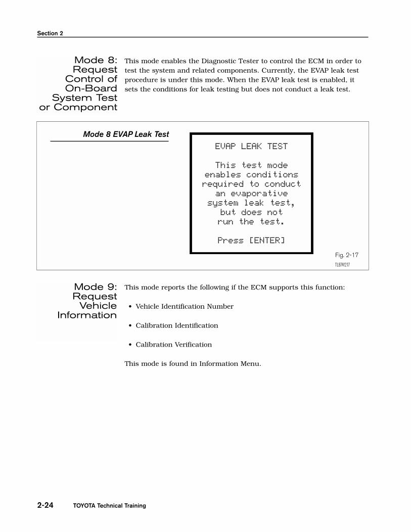
If a Readiness Test shows INCMPL, go to NON-CONTINUOUS TESTSscreen. For the O2 sensor monitor, go to O2S TEST RESULTS.
1.If the tests show Pass, the following may have occurred:
• the evaluation monitor did not operate
• the evaluation monitor did not finish
• the ECM withheld judgement
When a Readiness Test monitor shows INCMPL and Pass, it is unknownif the system monitor is good or if it has a problem. Further testingand/or driving is recommended to confirm system monitor operation.
Section 2
TOYOTA Technical Training2-42
No Determination Condition
From the data on these two screens, theECM has not determined if the EVAP
system is good or if there is a problem.Further driving may be needd.
Fig. 2-27
TL874f227
No DeterminationCondition
READINESS TEST
MISFIRE MON.......... AVAILFUEL SYS MON......... AVAILCOMP MON............. AVAILCAT EVAL............. COMPLHTD CAT EVAL........... N/AEVAP EVAL........... INCMPL2nd AIR EVAL........... N/AA/C EVAL............... N/AO2S EVAL............. COMPLO2S HTR EVAL......... COMPLEGR EVAL............. COMPL
NON-CONTINUOUS TESTS
Time$01 CID$01........ PassTime$02 CID$01........ PassTime$02 CID$02........ PassTime$02 CID$03........ PassTime$02 CID$04........ PassTime$04 CID$00........ PassTime$04 CID$02........ PassTime$05 CID$01........ PassTime$06 CID$01........ PassTime$07 CID$01........ Pass
NOTE

1. If one or more of the tests in the Time$0x… category show Fail, theevaluation monitor(s) did operate and the ECM detected a problem.
On-Board Diagnostic Systems
2-43Engine Control Systems II - Course 874
Fail Condition
Here, the ECM has detected a problem in the EVAP system. Since this
happened on the first trip, the DTC(s)can be found in Continuous Tests
(Mode 7) or Pending Codes. These arepending DTC(s).
Fig. 2-29
TL874f229
TID Screen
Fig. 2-28
• (TID)Time$01 = Catalyst Deterioration
• (TID)Time$02 = Evaporative System Deterioration
• (TID)Time$03 = Not Supported
• (TID)Time$04 = O2 Sensor Heater
• (TID)Time$05 = EGR
• (TID)Time$06 = A/F Sensor
• (TID)Time$07 = A/F Sensor Heater
• (TID)Time$08 = Thermostat Monitor
READINESS TEST
MISFIRE MON.......... AVAILFUEL SYS MON......... AVAILCOMP MON............. AVAILCAT EVAL............. COMPLHTD CAT EVAL........... N/AEVAP EVAL........... INCMPL2nd AIR EVAL........... N/AA/C EVAL............... N/AO2S EVAL............. COMPLO2S HTR EVAL......... COMPLEGR EVAL............. COMPL
NON-CONTINUOUS TESTS
Time$01 CID$01........ PassTime$02 CID$01........ FailTime$02 CID$02........ FailTime$02 CID$03........ FailTime$02 CID$04........ FailTime$04 CID$00........ PassTime$04 CID$02........ PassTime$05 CID$01........ PassTime$06 CID$01........ PassTime$07 CID$01........ Pass
Fail Condition -ProblemDetected
by the ECM

Section 2
TOYOTA Technical Training2-44
Go to CONTINUOUS TESTS (Mode 7) screen or PENDING CODESscreen.
The DTC listed may not be valid. A second trip is needed to confirm theDTC.
1.Vehicle must be cold, ambient temperature approximately between10°C - 35°C (50°F - 95°F).
2.Fuel level between 1/4 to 3/4.
3. Intake Air Temperature (IAT) and Engine Coolant Temperature (ECT)sensors within 6.5°C (12°F) of each other.
4.DO NOT CLEAR CODES!
5.Go to Readiness Test screen.
6.Drive the vehicle according to the same pattern as outlined earlier.Note the state of evaluation monitor(s). This procedure may takeapproximately 20 minutes or more. Do not shut off the engine –the results will be invalid.
NOTE
Pending DTCs
The Continuous Tests orPending Codes showedthe DTCs. These DTCs
do not show upanywhere else. These
DTCs may not be valid,but indicates a possible
problem. A second trip isneeded to confirm.
Fig. 2-30
TL874f230
Second TripProcedure
CONTINUOUS TESTS ECU: $10 (Engine) Number of Tests: 3
P0440 EVAP Control System Malfunction
P0441 EVAP Control System Incorrect Purge Flow
P0446 EVAP Control System Vent Control Circuit Malfunction
PENDING CODES ECU: ENGINE Number of DTCs: 3
P0440 EVAP Control System Malfunction
P0441 EVAP Control System Incorrect Purge Flow
P0446 EVAP Control System Vent Control Circuit Malfunction
On-Board Diagnostic Systems
2-45Engine Control Systems II - Course 874
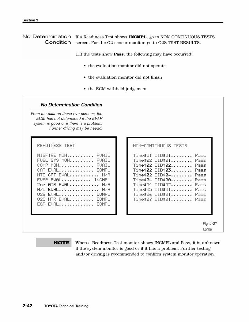
If a Readiness Test changes to COMPL, the evaluation monitor hasoperated. Check for any stored DTCs.
• If a DTC has stored, the problem has been detected and confirmed by the ECM.
• If no DTC was found, the monitor operated but no problem wasdetected.
There are situations where the Readiness Test may stay INCMPL, but the MIL will illuminate on the second trip (if two trip DTC). In this case, a fault has been detected and you should troubleshoot the displayedDTC(s).
Second Trip Procedure
Fig. 2-31
TL874f231
READINESS TEST
MISFIRE MON.......... AVAILFUEL SYS MON......... AVAILCOMP MON............. AVAILCAT EVAL............. COMPLHTD CAT EVAL........... N/AEVAP EVAL........... INCMPL2nd AIR EVAL........... N/AA/C EVAL............... N/AO2S EVAL............. COMPLO2S HTR EVAL......... COMPLEGR EVAL............. COMPL
P0440 EVAP Control System Malfunction
P0441 EVAP Control System Incorrect Purge Flow
P0446 EVAP Control System Vent Control Circuit Malfunction
Section 2
TOYOTA Technical Training2-46
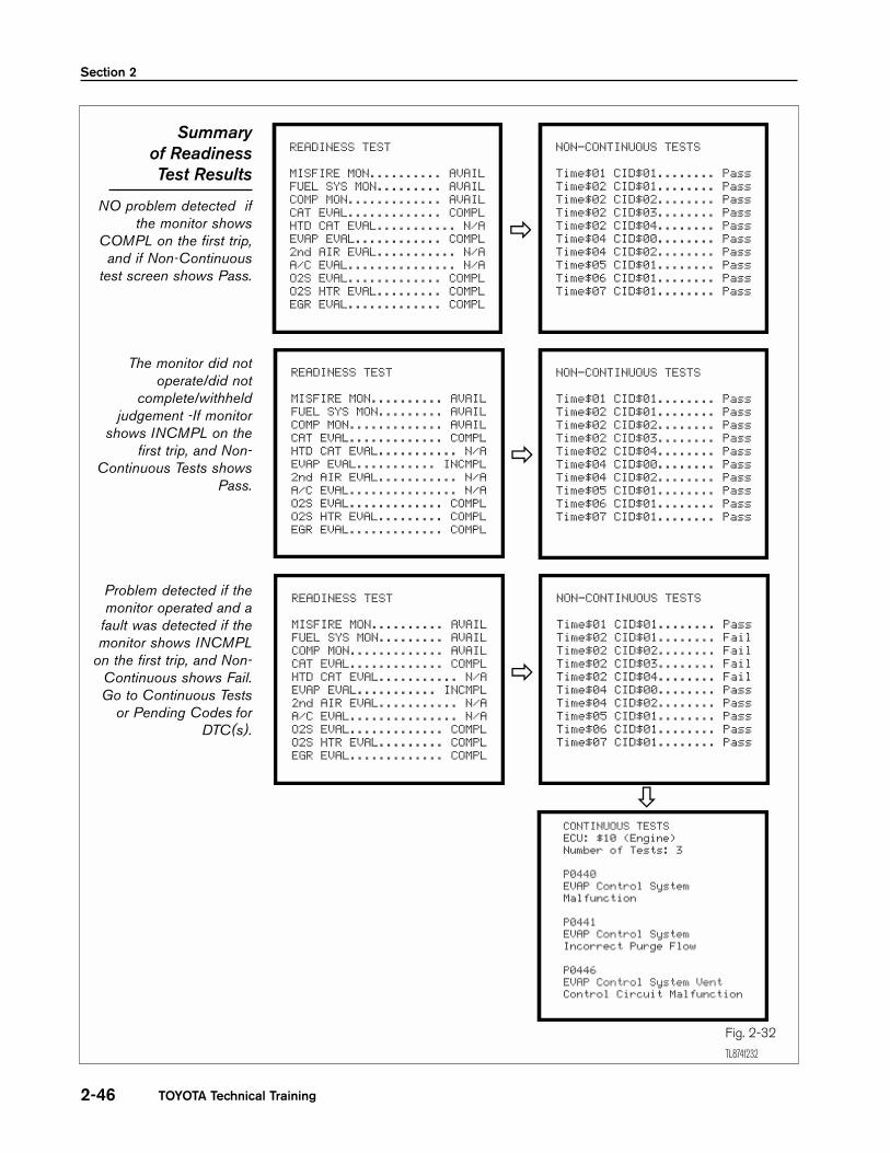
Summaryof ReadinessTest Results
NO problem detected ifthe monitor shows
COMPL on the first trip,and if Non-Continuous
test screen shows Pass.
The monitor did notoperate/did not
complete/withheldjudgement -If monitor
shows INCMPL on thefirst trip, and Non-
Continuous Tests showsPass.
Problem detected if themonitor operated and a
fault was detected if themonitor shows INCMPL
on the first trip, and Non-Continuous shows Fail.Go to Continuous Tests
or Pending Codes forDTC(s).
READINESS TEST
MISFIRE MON.......... AVAILFUEL SYS MON......... AVAILCOMP MON............. AVAILCAT EVAL............. COMPLHTD CAT EVAL........... N/AEVAP EVAL............ COMPL2nd AIR EVAL........... N/AA/C EVAL............... N/AO2S EVAL............. COMPLO2S HTR EVAL......... COMPLEGR EVAL............. COMPL
NON-CONTINUOUS TESTS
Time$01 CID$01........ PassTime$02 CID$01........ PassTime$02 CID$02........ PassTime$02 CID$03........ PassTime$02 CID$04........ PassTime$04 CID$00........ PassTime$04 CID$02........ PassTime$05 CID$01........ PassTime$06 CID$01........ PassTime$07 CID$01........ Pass
READINESS TEST
MISFIRE MON.......... AVAILFUEL SYS MON......... AVAILCOMP MON............. AVAILCAT EVAL............. COMPLHTD CAT EVAL........... N/AEVAP EVAL........... INCMPL2nd AIR EVAL........... N/AA/C EVAL............... N/AO2S EVAL............. COMPLO2S HTR EVAL......... COMPLEGR EVAL............. COMPL
NON-CONTINUOUS TESTS
Time$01 CID$01........ PassTime$02 CID$01........ FailTime$02 CID$02........ FailTime$02 CID$03........ FailTime$02 CID$04........ FailTime$04 CID$00........ PassTime$04 CID$02........ PassTime$05 CID$01........ PassTime$06 CID$01........ PassTime$07 CID$01........ Pass
CONTINUOUS TESTS ECU: $10 (Engine) Number of Tests: 3
P0440 EVAP Control System Malfunction
P0441 EVAP Control System Incorrect Purge Flow
P0446 EVAP Control System Vent Control Circuit Malfunction
Fig. 2-32
TL874f232
�
�
�
�

On-Board Diagnostic Systems
2-47Engine Control Systems II - Course 874
(1) Initial conditions:
• Battery positive voltage 11V or more
• Throttle valve fully closed
• Transmission in P or N position
• A/C switched OFF
(2) Turn the ignition switch OFF.
(3) Prepare the Diagnostic Tester.
(4) Connect the Diagnostic Tester to the DLC3.
(5) Turn the ignition switch ON and push the Diagnostic Tester switch ON.
(6) Switch the Diagnostic Tester from the normal mode to the checkmode (Check that the MIL flashes.)
If the Diagnostic Tester switches the ECM from the normal mode to thecheck mode or vice-versa, or if the ignition switch is turned from ON toACC or OFF during the check mode, the DTC(s) and Freeze Frame datawill be erased.
(7) Start the engine (The MIL goes out after engine start.)
(8) Simulate the conditions of the malfunction described by thecustomer.
Leave the ignition switch ON until you have checked the DTC(s), etc.
(9) After simulating the malfunction conditions, use the DiagnosticTester diagnosis selector to check the DTC(s) and Freeze Frame data, etc.
Take care not to turn the ignition switch OFF. Turning the ignition switchOFF switches the diagnosis system from check mode to normal mode, soall DTC(s), etc., are erased.
(10) After checking the DTC, inspect the applicable circuit.
Check ModeProcedure
NOTE
NOTE
NOTE

Section 2
TOYOTA Technical Training2-48
Worksheet ObjectivesFor troubleshooting OBD II concerns with the Diagnostic Tester, there are two major areas with information,Enhanced OBD II and CARB OBD II. In this worksheet, you will use the Diagnostic Tester to obtain relevantinformation, and observe the advantages different screens posses to the diagnosis of OBD II related concerns.
Tools and Equipment
• Vehicle Repair Manual
• Vehicle EWD
• Diagnostic Tester
• Hand Tool Set
Section 1: Features of Enhanced OBD II and CARB OBD II1. On the list below, note if the listed item is located in the ENHANCED OBD II or CARB OBD II section. Write
a very brief comment on the use/advantage of the following modes (if any).
WORKSHEET 2-1Diagnostic Tester Modes
Vehicle Year/Prod. Date Engine Transmission
Engine Control Systems II - Course 874 2-49
(Instructors’ Copy)
SCREEN TITLE
DATA LIST
NORMAL MODE
CHECK MODE
DTCs
REPAIR CONFIRMATION
ENHANCED OBD II CARB OBD II

Worksheet 2-1
TOYOTA Technical Training2-50
SCREEN TITLE
SNAP SHOT
FREEZE DATA
CLEAR DIAG INFO
O2S/RPM CHECK
READINESS TESTS
ACTIVE TESTS
ADVANCED OBD IIFUNCTIONS
NON-CONTINUOUS
CONTINUOUS
UNIT CONVERSION
PENDING CODES
O2S TEST RESULTS
ENHANCED OBD II CARB OBD II

Diagnostic Tester ModesName: __________________________________________________________ Date: _________________________
Review this sheet as you are doing the worksheet. Check each category after completing theworksheet and instructor presentation. Ask the instructor if you have questions. The commentssection is for you to write where to find the information, questions, etc.
I have questions I know I can
Topic Comment
Locate Enhanced and CARB OBD IIfunctions on the Diagnostic Tester
Engine Control Systems II - Course 874 2-51

TOYOTA Technical Training2-52
Worksheet 2-1

Worksheet ObjectivesTo accurately diagnose the condition of the vehicle based on Readiness Tests and Non-Continuous Testmodes.
CASE 1DTCs were cleared and the vehicle was driven with the DT connected. Based on the following screen shots,determine the status of the Readiness Tests (monitors) and determine if there is a problem
WORKSHEET 2-2Readiness Non-Continuous Test Modes
Vehicle Year/Prod. Date Engine Transmission
Engine Control Systems II - Course 874 2-53
(Instructors’ Copy)
READINESS TEST
MISFIRE MON.......... AVAILFUEL SYS MON......... AVAILCOMP MON............. AVAILCAT EVAL............. COMPLHTD CAT EVAL........... N/AEVAP EVAL............ COMPL2nd AIR EVAL........... N/AA/C EVAL............... N/AO2S EVAL............. COMPLO2S HTR EVAL......... COMPLEGR EVAL............. COMPL
NON-CONTINUOUS TESTS
Time$01 CID$01........ PassTime$02 CID$01........ PassTime$02 CID$02........ PassTime$02 CID$03........ PassTime$02 CID$04........ PassTime$04 CID$00........ PassTime$04 CID$02........ PassTime$05 CID$01........ PassTime$06 CID$01........ PassTime$07 CID$01........ Pass
Notes:
READINESS TEST MON
MISFIRE MON
FUEL SYS MON
COMP MON
CAT EVAL
EVAP EVAL
O2S EVAL
O2S HTR EVAL
EGR EVAL
Operate? Status?

Worksheet 2-2
TOYOTA Technical Training2-54
CASE 2DTCs were cleared and the vehicle was driven with the DT connected. Based on the following screen shots,determine the status of the Readiness Tests monitors and determine if there is a problem.
READINESS TEST
MISFIRE MON.......... AVAILFUEL SYS MON......... AVAILCOMP MON............. AVAILCAT EVAL............ INCMPLHTD CAT EVAL........... N/AEVAP EVAL........... INCMPL2nd AIR EVAL........... N/AA/C EVAL............... N/AO2S EVAL............. COMPLO2S HTR EVAL......... COMPLEGR EVAL............... N/A
NON-CONTINUOUS TESTS
Time$01 CID$01........ PassTime$02 CID$01........ PassTime$02 CID$02........ PassTime$02 CID$03........ PassTime$02 CID$04........ PassTime$04 CID$00........ PassTime$04 CID$02........ PassTime$05 CID$01........ PassTime$06 CID$01........ PassTime$07 CID$01........ Pass
Notes:
READINESS TEST MON
MISFIRE MON
FUEL SYS MON
COMP MON
CAT EVAL
EVAP EVAL
O2S EVAL
O2S HTR EVAL
EGR EVAL
Operate? Status?

Readiness Non-Continuous Test Modes
2-55
CASE 3DTCs were cleared and the vehicle was driven with the DT connected. Based on the following screen shots,determine the status of the Readiness Tests monitors and determine if there is a problem.
Engine Control Systems II - Course 874
READINESS TEST
MISFIRE MON.......... AVAILFUEL SYS MON......... AVAILCOMP MON............. AVAILCAT EVAL............. COMPLHTD CAT EVAL........... N/AEVAP EVAL........... INCMPL2nd AIR EVAL........... N/AA/C EVAL............... N/AO2S EVAL............. COMPLO2S HTR EVAL......... COMPLEGR EVAL............... N/A
NON-CONTINUOUS TESTS
Time$01 CID$01........ PassTime$02 CID$01........ PassTime$02 CID$02........ FailTime$02 CID$03........ PassTime$02 CID$04........ PassTime$04 CID$00........ PassTime$04 CID$02........ PassTime$05 CID$01........ PassTime$06 CID$01........ PassTime$07 CID$01........ Pass
Notes:
READINESS TEST MON
MISFIRE MON
FUEL SYS MON
COMP MON
CAT EVAL
EVAP EVAL
O2S EVAL
O2S HTR EVAL
EGR EVAL
Operate? Status?


![ON-BOARD DIAGNOSTIC [ENGINE CONTROL SYSTEM (FS)] … · ON-BOARD DIAGNOSTIC [ENGINE CONTROL SYSTEM (FS)] 01–02B–8 Freeze Frame PID Data Access Procedure 1. Perform the necessary](https://img.dokumen.tips/doc/110x75/5f0d31837e708231d439219b/on-board-diagnostic-engine-control-system-fs-on-board-diagnostic-engine-control.jpg)