Embed Size (px)
Citation preview

DISINFECTION OF PIPING
DECEMBER 2014 PWS CONTRACT NO. 13-40UTIL 15041-1
SECTION 15041
DISINFECTION OF PIPING
PART 1 -- GENERAL
1.01 DESCRIPTION This section describes requirements for disinfection by chlorination of potable and
recycled water mains, services, pipe appurtenances and connections. 1.02 QUALITY ASSURANCE
A. REFERENCES:
This section contains references to the following documents. They are a part of this
section as specified and modified. Where a referenced document contains references to other
standards, those documents are included as references under this section as if referenced directly.
In the event of conflict between the requirements of this section and those of the listed
documents, the requirements of this section shall prevail.
Unless otherwise specified, references to documents shall mean the documents in effect
at the time of Advertisement for Bids or Invitation to Bid (or on the effective date of the
Agreement if there were no Bids). If referenced documents have been discontinued by the
issuing organization, references to those documents shall mean the replacement documents
issued or otherwise identified by that organization or, if there are no replacement documents, the
last version of the document before it was discontinued. Where document dates are given in the
following listing, references to those documents shall mean the specific document version
associated with that date, regardless of whether the document has been superseded by a version
with a later date, discontinued or replaced.
Reference Title
AWWA B300 Standard for Hypochlorites
AWWA B301 Standard for Liquid Chlorine
AWWA C600 Installation of Ductile-Iron Water Mains and Their Appurtenances
AWWA C605 Underground Installation of Polyvinyl Chloride (PVC) Pressure Pipe
and Fittings for Water
AWWA C651 Standard for Disinfecting Water Mains
AWWA Manual
M11
Steel Pipe - A Guide for Design and Installation
AWWA C604 Installation of Buried Steel Water Pipe 4-In. and Larger

DISINFECTION OF PIPING
15041-2 PWS CONTRACT NO. 13-40UTIL DECEMBER 2014
1.04 SERVICE APPLICATION
All water mains and appurtenances taken out of service for inspection, repairs, or other
activity shall be disinfected before they are returned to service.
All new water mains and temporary high lines shall be disinfected prior to connection to
the City's existing system.
All components incorporated into a connection to the City's existing system shall be
disinfected prior to installation. 1.05 SUBMITTALS
A written disinfection and dechlorination plan signed by a certified chlorinator shall be
submitted to the Engineer for review and approval prior to starting disinfection or dechlorination
operations. Plan for disinfection method and procedure shall include equipment used to inject
the chlorine solution, gauges or scales to measure the rate at which chlorine is injected,
qualifications of personnel, testing location and schedule, source of water and water disposal
locations. Personnel performing the disinfection shall demonstrate a minimum of five years
experience in the chlorination and dechlorination of pipelines. Qualification of certified testing laboratory.
Four copies of bacteriological test results to the Construction Manager upon completion
of each test.
Emergency Response Plan. 1.06 DELIVERY, STORAGE AND HANDLING
Chlorination and dechlorination shall be performed by competent individuals
knowledgeable and experienced in the operation of the necessary application and safety
equipment in accordance with applicable Federal, State and Local laws and regulations. The
transport, storage and handling of these materials shall be performed in accordance with Code of
Federal Regulations (CFR) 1910.120 Hazardous Waste Operations and Emergency Response,
CFR 49.172 Hazardous Materials Regulations, and the General Industry Safety Orders of the
California Code of Regulations, Title 8, Section 5194. 1.07 CONCURRENT DISINFECTION AND HYDROSTATIC TESTING
The specified disinfection of the pipelines may be performed concurrently with the
hydrostatic testing in accordance with Section 15044. In the event repairs are necessary, as
indicated by the hydrostatic test, additional disinfection may be required by the Construction
Manager in accordance with this specification.

DISINFECTION OF PIPING
DECEMBER 2014 PWS CONTRACT NO. 13-40UTIL 15041-3
1.08 CONNECTION TO EXISTING MAINS
Prior to connection to existing mains, disinfection and bacteriological testing shall be
performed in accordance with this specification, and hydrostatic testing shall be performed per
Section 15044. A City Connection Permit is required authorizing connection to an existing
system shall and be given only on the basis of acceptable hydrostatic, disinfection and
bacteriological test results. Connection to existing mains shall be performed in accordance with
Section 15050.
PART 2 -- MATERIALS
2.01 CHLORINE (GAS)
Liquid chlorine contains 100-percent available chlorine and is packaged in steel
containers in net weights of 68.1kg (150 lb.) or 907.2kg (1 ton).
Liquid chlorine shall be used with appropriate gas flow chlorinators, heaters, and
injectors to provide a controlled, high-concentration solution feed to the water. The chlorinators
and injectors shall be the vacuum-operated type.
2.02 SODIUM HYPOCHLORITE (LIQUID)
Sodium hypochlorite is available in liquid form in glass or plastic containers, ranging in
size from 0.95 L (1 Qt.) to 18.93 L (5 Gal.). The solution contains approximately 10% to 15%
available chlorine.
2.03 TABLET OR GRANULAR HYPOCHLORITE
Tablet or granular hypochlorite may be used if a solution container is utilized to provide a
continuous feed method. PART 3 -- EXECUTION 3.01 GENERAL
Disinfection of pipelines shall not proceed until all appurtenances and any necessary
sample ports have been installed and the Construction Manager provides authorization.
Every effort shall be made to keep the water main and its appurtenances clean and dry
during the installation process.
All piping, valves, fittings, and appurtenances which become contaminated during
installation shall be cleaned, rinsed with potable water, and then sprayed or swabbed with a 5
percent sodium hypochlorite disinfecting solution prior to installation.

DISINFECTION OF PIPING
15041-4 PWS CONTRACT NO. 13-40UTIL DECEMBER 2014
Water mains under construction that become flooded by storm water, runoff, or
groundwater shall be cleaned by draining and flushing with metered potable water until clear
water is evident. Upon completion, the entire main shall be disinfected using a method approved
by the Construction Manager. 3.02 METHODS
A. CHLORINE (GAS):
Only vacuum-operated equipment shall be used. Direct-feed chlorinators, which operate
solely from gas pressure in the chlorine cylinder, shall not be permitted. The equipment shall
incorporate a backflow prevention device at the point of connection to the potable water source
used to fill the line being tested.
The chlorinating agent shall be applied at the beginning of the system to be chlorinated
and shall be injected through a corporation stop, a hydrant, or other approved connection to
ensure treatment of the entire system being disinfected.
Only a certified, licensed chlorination and testing contractor shall perform gas
chlorination work. The chlorination contractor must also possess a Grade II Treatment Plant
Operator Certification from the State of California if required by the Construction Manager.
B. SODIUM HYPOCHLORITE SOLUTION (LIQUID):
Sodium hypochlorite solution shall be used for cleaning and swabbing piping and
appurtenances immediately prior to installation and for disinfecting all components of
connections to the City's existing system.
Sodium hypochlorite solution may be used for the initial disinfection of newly installed
water mains. The solution shall be applied at a terminus of the system to be chlorinated using an
injector which can adjust the amount of solution being injected into the piping system. The
solution shall be injected in the appropriate concentration to achieve the specified concentration
range of chlorine throughout the entire piping system. Where pumping equipment is used in
conjunction with an injector, an integral backflow prevention device shall be used and connected
to the potable water supply.
Water trucks, pumping equipment, piping, appurtenances and all other equipment in
contact with potable water shall be disinfected prior to use.
Sodium hypochlorite solution may also be used to increase the total chlorine residual if
the concentration from the initial chlorination of the system is found to be low. The solution shall
be added to the system in sufficient amounts at appropriate locations to ensure that the
disinfecting solution is present at a concentration within the specified range throughout the
piping system.

DISINFECTION OF PIPING
DECEMBER 2014 PWS CONTRACT NO. 13-40UTIL 15041-5
3.03 PROCEDURE FOR DISINFECTING WATER MAINS AND APPURTENANCES
The pipeline shall be filled at a rate not to exceed 1,135 liters per minute (300 GPM) or a
velocity of 0.3m per second (1 foot per second), whichever is less.
Disinfection shall result in a total chlorine concentration of not less than 25-mg/l.
This concentration shall be evenly distributed throughout the system to be disinfected, using a
continuous feed method of chlorination.
All valves shall be operated with the disinfection solution present in the pipeline. All
appurtenances such as air-vacuum relief valves, blowoffs, hydrants, backflow prevention
devices, and water service laterals shall be flushed with the treated water a sufficient length of
time to ensure a chlorine concentration within the specified range in all components of each
appurtenance. (Note the limitations for discharge of chlorinated water outlined below.)
The Construction Manager will verify the presence of the disinfection solution
throughout the system by sampling and testing for acceptable chlorine concentrations at the
various appurtenances and/or at the test ports provided by the Contractor. Areas of the system
found to be below the specified chlorine concentration level shall receive additional flushing as
noted above and/or additional disinfection solution as necessary. (Note the limitations for
discharge of chlorinated water outlined below.) Addition of disinfection solution after the initial
charging of the line shall be made by either the liquid chlorine (gas) method, or the sodium
hypochlorite method as directed by the Construction Manager.
The chlorinated water shall be retained in the system for a minimum of 24 hours. The
Construction Manager will test the total chlorine residual. The system shall contain a total
chlorine residual of not less than 80% of the initial total chlorine residual before the 24-hour
soaking period began. If the total chlorine residual has decreased more than 20%, the system
shall be soaked for an additional 24-hour period. If the total chlorine residual has not deceased
after this additional 24-hour period, the system shall be flushed in accordance with the procedure
detailed herein. If the total chlorine residual has decreased, the system shall be flushed in
accordance with the procedure detailed herein, and shall be re-disinfected.
Following a successful retention period as determined by the Construction Manager, the
chlorinated water shall be flushed from the system at its extremities and at each appurtenance,
using potable water from a source designated by the Construction Manager. The minimum water
velocity during flushing shall be 0.9 meters per second (3 feet per second) or as directed by the
Construction Manager. Flushing shall continue until the replacement water in the new system is
equal in chlorine residual to the potable source of supply as verified by the City. (Note the
limitations for discharge of chlorinated water outlined below.)
The Contractor shall contract with a State certified sampling laboratory to perform
sampling, transport samples and perform bacteriological sampling and testing as specified
herein.

DISINFECTION OF PIPING
15041-6 PWS CONTRACT NO. 13-40UTIL DECEMBER 2014
3.04 DISCHARGE OF CHLORINATED WATER
Indiscriminate onsite disposal or discharge to sewer systems, storm drains, drainage
courses or surface waters of chlorinated water is prohibited.
In locations where chlorine neutralization is required, the reducing agent shall be applied
to the water as it exits the piping system. The Contractor shall monitor the chlorine residual
during the discharge operations. Total residual chlorine limits in these locations, and for the
discharge of chlorinated water from the testing of pipelines to surface waters of the San Diego
Region are as follows: Total Residual Chlorine Effluent Limitations 30-Day Average - 0.002 mg/l Average Daily Maximum - 0.008 mg/l Instantaneous Maximum - 0.02 mg/l
The various methods of dechlorination available can remove residual chlorine to
concentrations below standard analytical methods of detection, 0.02 mg/l, which will assure
compliance with the effluent limit. The Contractor will perform all necessary tests, keeping and
providing records to the Construction Manager to ensure that the total residual chlorine effluent
limitations listed above are met.
In locations where no hazard to the environment is evident based on the joint examination
described above, the chlorinated water may be broadcast for dust control on the surface of the
immediate site. Care shall be exercised in broadcasting the water to prevent runoff.
3.05 BACTERIOLOGICAL TESTING
The Contractor shall employ a State certified laboratory to perform bacteriological
sampling and testing of all new system installations. The testing methodology employed by the
City shall be as set forth in "Standard Methods for the Examination of Water and Waste Water"
(current edition). Testing requirements are as set forth in the California Domestic Water Quality
and Monitoring Regulations and commensurate with current requirements for surface water
testing. The testing laboratory will analyze the samples for the presence of coliform bacteria and
heterotrophic-type bacteria (heterotrophic plate count). The evaluation criteria employed by the
City for a passing test sample is as follows:
Coliform bacteria: no positive sample, and
Heterotrophic plate count (HPC): 500 colony forming units/ml or less. 3.06 REDISINFECTION
If the initial disinfection fails to produce satisfactory bacteriological test results, the
pipeline system shall be re-flushed and re-sampled. If the second set of samples does not produce
satisfactory results, the pipeline system shall be re-chlorinated, flushed, and re-stamped. The

DISINFECTION OF PIPING
DECEMBER 2014 PWS CONTRACT NO. 13-40UTIL 15041-7
chlorination, flushing, and sampling procedure shall continue until satisfactory results are
obtained. Re-disinfection and retesting shall be at the Contractor's expense. 3.07 DISINFECTING TIE-INS AND CONNECTIONS
Pipes, fittings, valves and all other components incorporated into tie connections with the
City's existing system shall be spray disinfected or swabbed with a liquid chlorine solution in
accordance with AWWA C651 and as specified herein. Upon connection to the main, the line
shall be flushed as directed by the Construction Manager. Disinfection by this method is
generally limited to assemblies of 20' or less in length. Alternate methods such as
"predisinfection" prior to installation in accordance with AWWA C651 may be required at the
discretion of the Construction Manager.
** END OF SECTION **

DISINFECTION OF PIPING
15041-8 PWS CONTRACT NO. 13-40UTIL DECEMBER 2014
THIS PAGE INTENTIONALLY LEFT BLANK

TESTING OF GRAVITY
SEWER PIPELINES
DECEMBER 2014 PWS CONTRACT NO. 13-40UTIL 15043-1
SECTION 15043
TESTING OF GRAVITY SEWER PIPELINES
PART 1 - GENERAL
1.01 DESCRIPTION
The Contractor shall furnish all tools, equipment, materials, and supplies and shall
perform all labor required to complete the work as indicated on the Drawings and specified
herein.
This section covers the performance of all pipeline flushing and testing, complete, for
sanitary sewer system piping as specified herein and in accordance with the requirements of the
Contract Documents.
1.02 REFERENCE SPECIFICATIONS, CODES AND STANDARDS
Comply with the applicable reference specifications as specified in the General
Provisions.
1.03 CONTRACTOR SUBMITTALS
Submittals shall be made in accordance with the General Provisions.
The Contractor shall submit in writing all proposed plans for testing, and for water
conveyance, control and disposal. The Contractor shall also submit written notice 48 hours in
advance of the proposed testing schedule for review and concurrence of the Construction
Manager.
1.05 QUALITY ASSURANCE (NOT USED)
PART 2 – PRODUCTS
2.01 GENERAL
Temporary valves, plugs, bulkheads, and other air pressure testing and water control
equipment and materials shall be provided by the Contractor subject to the Construction
Manager's review. No materials shall be used which will be injurious to pipeline structure and
future function. Air test gages shall be laboratory-calibrated annually. At the discretion of the
Construction Manager, gages shall be recalibrated by a certified laboratory at the Contractor's
expense prior to the leakage test.

TESTING OF GRAVITY
SEWER PIPELINES
15043-2 PWS CONTRACT NO. 13-40UTIL DECEMBER 2014
PART 3 – EXECUTION
3.01 GENERAL
Unless otherwise specified, water for testing will be furnished by the Contractor; and, the
Contractor shall make all necessary provisions for conveying the water from the Agency-
designated source to the points of use.
Release of water from pipelines, after testing has been completed, shall be performed as
directed by the Construction Manager.
All testing operations shall be performed in the presence of the Construction Manager.
3.02 SEWER PIPE CLEANING
All sewer pipe shall be thoroughly flushed with clean water, from access-hole to access-
hole with an appropriately sized inflatable ball.
All construction debris and water shall be removed from each access-hole prior to
removal of expandable plugs.
Water used in flushing the new sewer mains and laterals shall not be discharged into the
existing sewer system.
3.03 TESTING OF PIPELINE
A. GENERAL:
All gravity sewer pipes and service laterals shall be tested for exfiltration and/or
infiltration and deflection, as specified. Sewer pipelines shall be backfilled prior to testing.
All leakage tests of sanitary sewer systems shall be in conformance with SSPWC Section 306-
1.4.1.
Water Exfiltration Test shall be in conformance with SSPWC Section 306-1.4.2.
Water Infiltration Test shall be in conformance with SSPWC Section 306-1.4.3.
Unless otherwise specified, infiltration will be measured by the Contractor using measuring
devices approved by the Construction Manager.
Air Pressure Test shall be in conformance with SSPWC Section 306-1.4.4.
At the Contractor's option, joints may be air tested individually, joint by joint, with the
use of specialized equipment. The Contractor shall submit its joint testing procedure for the
Construction Manager's review and approval prior to testing. Prior to each test, the pipe at the
joint shall be wetted with water. The maximum test pressure shall be 3.0 psi unless otherwise
specified. The minimum allowable pressure drop shall be 1.0 psi over a 30-second test period.

TESTING OF GRAVITY
SEWER PIPELINES
DECEMBER 2014 PWS CONTRACT NO. 13-40UTIL 15043-3
Water Pressure Test shall be in conformance with SSPWC Section 306-1.4.5.
B. DEFLECTION TEST:
All flexible and semi-rigid main line pipe shall be tested in accordance with SSPWC
Sections 306-1.2.12 and 306-1.2.13 for deflection, joint displacement, or any other obstruction
by passing a rigid mandrel through the pipe by hand, not less than 30 days after completion of the
trench backfill, but prior to permanent resurfacing. The mandrel shall be a full circle, solid
cylinder, or a rigid, non-adjustable, odd-numbered leg (9 leg minimum) steel cylinder, accepted
by the Construction Manager as to design and manufacture. Unless otherwise specified, the
circular cross section of the mandrel shall have a diameter of at least 95 percent of the specified
average inside diameter of the pipe and the minimum length of the circular portion of the
mandrel shall be equal to the nominal diameter of the pipe. Obstructions encountered by the
mandrel shall be corrected by the Contractor.
3.04 CLOSED CIRCUIT TELEVISION INSPECTION
A closed circuit television inspection shall ne conducted of new sewer lines after sewer
pipe cleaning and mandrel testing.
Closed circuit television inspections shall be performed in accordance with the SSPWC,
500-1.1.5. Video documentation shall be provided in digital format (DVD).
All defects and evidence of reverse slope by ponding of water or dips in pipe alignment
revealed by the closed circuit television inspection shall be repaired to the satisfaction of the
Construction Manager at the Contractor’s expense.
** END OF SECTION **

TESTING OF GRAVITY
SEWER PIPELINES
15043-4 PWS CONTRACT NO. 13-40UTIL DECEMBER 2014
THIS PAGE INTENTIONALLY LEFT BLANK

HYDROSTATIC TESTING OF
PRESSURE PIPELINES
DECEMBER 2014 PWS CONTRACT NO. 13-40UTIL 15044-1
SECTION 15044
HYDROSTATIC TESTING OF PRESSURE PIPELINES
PART 1 -- GENERAL
1.01 DESCRIPTION
This section describes the requirements and procedures for pressure and leakage testing
of all pressure mains.
1.02 QUALITY ASSURANCE
A. REFERENCES:
This section contains references to the following documents. They are a part of this
section as specified and modified. Where a referenced document contains references to other
standards, those documents are included as references under this section as if referenced directly.
In the event of conflict between the requirements of this section and those of the listed
documents, the requirements of this section shall prevail.
Unless otherwise specified, references to documents shall mean the documents in effect
at the time of Advertisement for Bids or Invitation to Bid (or on the effective date of the
Agreement if there were no Bids). If referenced documents have been discontinued by the
issuing organization, references to those documents shall mean the replacement documents
issued or otherwise identified by that organization or, if there are no replacement documents, the
last version of the document before it was discontinued. Where document dates are given in the
following listing, references to those documents shall mean the specific document version
associated with that date, regardless of whether the document has been superseded by a version
with a later date, discontinued or replaced.
Reference Title
ASTM F2164 Standard Practice for Field Leak Testing of Polyethylene (PE)
and Crosslinked Polyethylene (PEX) Pressure Piping Systems
Using Hydrostatic Pressure
AWWA C600 Installation of Ductile-Iron Water Mains and Their
Appurtenances
AWWA C605 Underground Installation of Polyvinyl Chloride (PVC) Pressure
Pipe and Fittings for Water
AWWA C651 Standard for Disinfecting Water Mains
AWWA Manual M11 Steel Pipe - A Guide for Design and Installation
AWWA C604 Installation of Buried Steel Water Pipe 4-In. and Larger
HYDROSTATIC TESTING OF
PRESSURE PIPELINES
15044-2 PWS CONTRACT NO. 13-40UTIL DECEMBER 2014
Reference Title
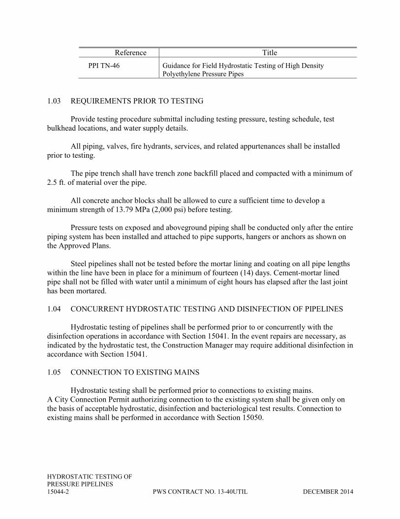
PPI TN-46 Guidance for Field Hydrostatic Testing of High Density
Polyethylene Pressure Pipes
1.03 REQUIREMENTS PRIOR TO TESTING
Provide testing procedure submittal including testing pressure, testing schedule, test
bulkhead locations, and water supply details.
All piping, valves, fire hydrants, services, and related appurtenances shall be installed
prior to testing.
The pipe trench shall have trench zone backfill placed and compacted with a minimum of
2.5 ft. of material over the pipe.
All concrete anchor blocks shall be allowed to cure a sufficient time to develop a
minimum strength of 13.79 MPa (2,000 psi) before testing.
Pressure tests on exposed and aboveground piping shall be conducted only after the entire
piping system has been installed and attached to pipe supports, hangers or anchors as shown on
the Approved Plans.
Steel pipelines shall not be tested before the mortar lining and coating on all pipe lengths
within the line have been in place for a minimum of fourteen (14) days. Cement-mortar lined
pipe shall not be filled with water until a minimum of eight hours has elapsed after the last joint
has been mortared.
1.04 CONCURRENT HYDROSTATIC TESTING AND DISINFECTION OF PIPELINES
Hydrostatic testing of pipelines shall be performed prior to or concurrently with the
disinfection operations in accordance with Section 15041. In the event repairs are necessary, as
indicated by the hydrostatic test, the Construction Manager may require additional disinfection in
accordance with Section 15041.
1.05 CONNECTION TO EXISTING MAINS
Hydrostatic testing shall be performed prior to connections to existing mains.
A City Connection Permit authorizing connection to the existing system shall be given only on
the basis of acceptable hydrostatic, disinfection and bacteriological test results. Connection to
existing mains shall be performed in accordance with Section 15050.

HYDROSTATIC TESTING OF
PRESSURE PIPELINES
DECEMBER 2014 PWS CONTRACT NO. 13-40UTIL 15044-3
PART 2 -- MATERIALS
2.01 WATER
Potable water shall be used for hydrostatic testing of potable and recycled water mains.
Potable water shall be supplied by a Construction Manager-approved source. Make-up
water for testing shall also be potable water.
A chlorinated water solution, in accordance with Section 15041, shall be used to charge
the line and for make-up water when hydrostatic testing and disinfection operations are
combined.
Meet all applicable state and local requirements for disposal of testing water.
2.02 CONNECTIONS
A. Testing water shall be supplied through a metered connection equipped with a
backflow prevention device in accordance with Section 15112 at the point of
connection to the potable water source used.
B. The Contractor shall provide any temporary piping needed to deliver potable
water to the piping that is to be tested. Temporary piping shall be in accordance
with Section 15050.
PART 3 -- EXECUTION
3.1 GENERAL
All water systems shall be pre-tested to insure passage of test prior to scheduling official
test with inspector.
The Contractor shall provide the Construction Manager with a minimum of 48 hours'
notice prior to the requested date and time for hydrostatic tests.
The Contractor shall furnish all labor, materials, tools, and equipment for testing.
Temporary blocking during the tests will be permitted only at temporary plugs, caps or
where otherwise directed by the Construction Manager.
All valves and appurtenances shall be operated during the test period. The test shall be
conducted with valves in the open position. The Contractor is not permitted to operate any
valves on the City’s system.

HYDROSTATIC TESTING OF
PRESSURE PIPELINES
15044-4 PWS CONTRACT NO. 13-40UTIL DECEMBER 2014
At the onset of testing, all valves, air vacuum assemblies, blowoffs, and services shall be
monitored for possible leakage and repairs made, if necessary, before the test proceeds. The
appurtenances shall be monitored through the duration of the testing.
For pipe with porous lining, such as cement mortar, the pipe shall be filled with water and
placed under a slight pressure for a minimum of forty-eight (48) hours prior to the actual
hydrostatic test.
Testing shall be made before connecting the new line with the existing City pipes and
mains.
The pipeline should be filled at a rate such that the velocity of flow is less than 1 fps.
Maximum length of pipe to be included in any one (1) test shall not exceed 2,500 linear
feet or vertical elevation difference of 58 feet.
3.02 FIELD TEST PROCEDURE
Before applying the specified test pressure, care shall be taken to release all air within the
pipe and appurtenances to be tested. Air shall be released through services, fire hydrants, air
release valves, or other approved locations.
The leakage shall be considered as the total amount of water pumped into the pipeline
during the test period.
Apply and maintain the test pressure by means of a hydraulic force pump.
Maintain the test pressure for the following duration by restoring it whenever it falls an
amount of 5 psi:
Pipe Diameter (inches) Hours 18 and less 4 20 to 36 8 Greater than 36 24
After the test pressure is reached, use a meter to measure the additional water added to
maintain the pressure. This amount of water is the loss due to leakage in the piping system. The
allowable leakage for various sizes of PUC & DIP with rubber gaskets are shown in the
following table:

HYDROSTATIC TESTING OF
PRESSURE PIPELINES
DECEMBER 2014 PWS CONTRACT NO. 13-40UTIL 15044-5
TYPE OF PIPE: P.V.C. & D.I.P. CLASSES: 150 & 200 Pipe Sizes Allowable Leakage (inches) Gals/4 hrs/1000’ of pipe 4” .33 Gals 6” .50 Gals 8” .66 Gals Pipe Sizes Allowable Leakage (inches) Gals/4 hrs/1000’ of pipe 10” .83 Gals. 12” .99 Gals. 14” 1.16 Gals. 16” 1.32 Gals. 18” 1.49 Gals.
20” 1.66 Gals. 24” 1.98 Gals.
The allowable leakage for welded steel pipe shall be zero gallons.
The allowable leakage for piping having threaded, brazed, or welded (including solvent
welded) joints shall be zero gallons.
Repair and retest any pipes showing leakage rates greater than that allowed in the above
criteria.
3.03 TEST PRESSURE
Test pressures shall be as specified in Section 15050. Pressure shall be maintained for a
duration shown in section 3.2 and shall be repumped when it falls an amount of 5 p.s.i.
The test pump gauge and meter shall be connected to the water main at a location other
than the highest point in the line, in order to allow release of air from the high point. Means shall
be provided for accurately measuring the quantity of water pumped through a meter and pumped
into the pipe immediately, during and after the test period in order to maintain or restore the
initial test pressure. All pipe, fittings, valves, services and appurtenances shall be subjected to
the hydrostatic test and irrespective of the measured quantity of leakage, all detectable leaks shall
be repaired by the Contractor at the contractor’s expense and no cost to Carlsbad Municipal
Water District.

HYDROSTATIC TESTING OF
PRESSURE PIPELINES
15044-6 PWS CONTRACT NO. 13-40UTIL DECEMBER 2014
If a tested system is damaged or a leak occurs after official test the entire system or
portion of system will be retested as directed by Construction Manager.
** END OF SECTION **

PIPING SYSTEMS
DECEMBER 2014 PWS CONTRACT NO. 13-40UTIL 15050-1
SECTION 15050
PIPING SYSTEMS
PART 1 -- GENERAL
1.01 DESCRIPTION
A. SCOPE:
This section specifies systems of process piping, general requirements for piping systems
and requirements for maintenance of potable water service.
Detailed specifications for the components listed on the Piping System Specification
Sheets are found in other sections of Division 15. This section shall be used in conjunction with
those sections.
B. DEFINITIONS:
Pressure terms used in Section 15050 and elsewhere in Division 15 are defined as
follows:
1. MAXIMUM: The greatest continuous pressure at which the piping
system operates.
2. TEST: The hydrostatic pressure used to determine system acceptance.
1.02 QUALITY ASSURANCE
A. REFERENCES:
This section contains references to the following documents. They are a part of this
section as specified and modified. Where a referenced document contains references to other
standards, those documents are included as references under this section as if referenced directly.
In the event of conflict between the requirements of this section and those of the listed
documents, the requirements of this section shall prevail.
Unless otherwise specified, references to documents shall mean the documents in effect
at the time of Advertisement for Bids or Invitation to Bid (or on the effective date of the
Agreement if there were no Bids). If referenced documents have been discontinued by the
issuing organization, references to those documents shall mean the replacement documents
issued or otherwise identified by that organization or, if there are no replacement documents, the
last version of the document before it was discontinued. Where document dates are given in the
following listing, references to those documents shall mean the specific document version

PIPING SYSTEMS
15050-2 PWS CONTRACT NO. 13-40UTIL DECEMBER 2014
associated with that date, regardless of whether the document has been superseded by a version
with a later date, discontinued or replaced.
Reference Title
AASHTO
M36/M36M
Metallic (Zinc or Aluminum) Coated Corrugated Steel
Culverts and Underdrains
ANSI A13.1 Scheme for the Identification of Piping Systems
ANSI B1.20.1 Pipe Threads, General Purpose (Inch)
ANSI B16.1 Cast Iron Pipe Flanges and Flanged Fittings Class 25, 125,
250, and 800
ANSI B16.3 Malleable Iron Threaded Fittings Class 150 and 300
ANSI B16.5 Pipe Flanges and Flanged Fittings
ANSI B16.9 Factory-Made Wrought Steel Buttwelding Fittings
ANSI B16.11 Forged Steel Fittings, Socket Welding and Threaded
ANSI B16.12 Cast Iron Threaded Drainage Fittings
ANSI B16.22 Wrought Copper and Copper Alloy Solder Joint Pressure
Fittings
ANSI B16.26 Cast Copper Alloy Fittings for Flared Copper Tubes
ANSI B31.1 Power Piping
ANSI B31.3 Chemical Plant and Petroleum Refinery Piping
ASME Section IX Boiler and Pressure Vessel Code; Welding and Brazing
Qualifications
ASTM A47 Malleable Iron Castings
ASTM A53 Pipe, Steel, Black and Hot Dipped, Zinc-Coated Welded and
Seamless
ASTM A74 Cast Iron Soil Pipe and Fittings
ASTM A105/A105M Forgings, Carbon Steel, for Piping Components
ASTM A106 Seamless Carbon Steel Pipe for High-Temperature Service
ASTM A126 Standard Specification for Gray Iron Castings for Valves,
Flanges, and Pipe Fittings
ASTM A197 Cupola Malleable Iron
ASTM A234/A234M Pipe Fittings of Wrought Carbon Steel and Alloy Steel for
Moderate and Elevated Temperatures
ASTM A312/A312M Seamless and Welded Austenitic Stainless Steel Pipe
ASTM A403/A403M Wrought Austenitic Stainless Steel Piping Fittings

PIPING SYSTEMS
DECEMBER 2014 PWS CONTRACT NO. 13-40UTIL 15050-3
Reference Title
ASTM A536 Ductile Iron Castings
ASTM A570/A570M Hot-Rolled Carbon Steel Sheet and Strip, Structural Quality
ASTM B88 Seamless Copper Water Tube
ASTM C76 Reinforced Concrete Culvert, Storm Drain, and Sewer Pipe
ASTM C296 Asbestos-Cement Pressure Pipe
ASTM C443-REV A Standard Specification for Joints for Circular Concrete Sewer
and Culvert Pipe, Using Rubber Gaskets
ASTM C564 Rubber Gaskets for Cast Iron Soil Pipe and Fittings
ASTM D1248 Polyethylene Plastics Molding and Extrusion Materials
ASTM D1784 Rigid Poly (Vinyl Chloride) (PVC) Compounds and
Chlorinated Poly(Vinyl Chloride) (CPVC) Compounds
ASTM D1785 Poly (Vinyl Chloride) (PVC) Plastic Pipe, Schedules 40, 80,
and 120
ASTM D2241 Poly (Vinyl Chloride) (PVC) Plastic Pipe (SDR-PR)
ASTM D2513 Thermoplastic Gas Pressure Pipe, Tubing, and Fittings
ASTM D2665 Poly (Vinyl Chloride) (PVC) Plastic Drain, Waste, and Vent
Pipe and Fittings
ASTM D2996 Filament-Wound Reinforced Thermosetting Resin Pipe
ASTM D3034 Standard Specification for Type PSM Poly (Vinyl Chloride)
(PVC) Sewer Pipe and Fittings
ASTM D3261 Butt Fusion Polyethylene (PE) Plastic Fittings for
Polyethylene (PE) Plastic Pipe and Tubing
ASTM D4174 Cleaning, Flushing, and Purification of Petroleum Fluid
Hydraulic Systems
ASTM D4101 Propylene Plastic Injection and Extrusion Materials
ASTM F441 Chlorinated Poly (Vinyl Chloride) (CPVC) Plastic Pipe,
Schedules 40 and 80
AWWA C105 Polyethylene Encasement for Ductile-Iron Piping for Water
and Other Liquids
AWWA C110 Ductile-Iron and Gray-Iron Fittings, 3 Inch Through 48 Inch,
for Water and Other Liquids
AWWA C111 Rubber-Gasket Joints for Ductile-Iron and Gray-Iron Pressure
Pipe and Fittings
AWWA C115 Flanged Ductile-Iron and Gray-Iron Pipe with Threaded
Flanges

PIPING SYSTEMS
15050-4 PWS CONTRACT NO. 13-40UTIL DECEMBER 2014
Reference Title
AWWA C151 Ductile-Iron Pipe, Centrifugally Cast in Metal Molds or
Sand-Lined Molds, for Water or Other Liquids
AWWA C200 Steel Water Pipe 6 Inches and Larger
AWWA C205 Cement-Mortar Protective Lining and Coating for Steel
Water Pipe--4 In. and Larger--Shop Applied
AWWA C206 Field Welding of Steel Water Pipe
AWWA C207 Steel Pipe Flanges for Waterworks Services--Sizes 4 In.
through 144 In.
AWWA C208 Dimensions for Fabricated Steel Water Pipe Fittings
AWWA C209 Cold-Applied Tape Coating for Special Sections,
Connections, and Fittings for Steel Water Pipelines
AWWA C210 Liquid Epoxy Coating Systems for the Interior and Exterior
of Steel Water Pipe
AWWA C214 Tape Coating Systems for the Exterior of Steel Water
Pipelines
AWWA C301 Prestressed Concrete Pressure Pipe, Steel Cylinder Type, for
Water and Other Liquids
AWWA C303 Reinforced Concrete Pressure Pipe--Steel Cylinder Type,
Pretensioned, for Water and Other Liquids
AWWA C600 Installation of Ductile-Iron Water Mains and Their
Appurtenances
AWWA C651 Disinfecting Water Mains
AWWA C900 Polyvinyl Chloride (PVC) Pressure Pipe, 4 Inches Through
12 Inches, for Water
AWWA M11 Steel Pipe--A Guide for Design and Installation
CISPI 301 Specification Data for Hubless Cast Iron Sanitary System
with No-Hub Pipe and Fittings
FEDSPEC
L-C-530B(1)
Coating, Pipe, Thermoplastic Resin or Thermosetting Epoxy
MIL-H-13528B Hydrochloric Acid, Inhibited, Rust Removing
MIL-STD-810C Environmental Test Methods
SAE J1227 Assessing Cleanliness of Hydraulic Fluid Power Components
and Systems
UPC Uniform Plumbing Code

PIPING SYSTEMS
DECEMBER 2014 PWS CONTRACT NO. 13-40UTIL 15050-5
B. FITTINGS AND COUPLING COMPATIBILITY:
To assure uniformity and compatibility of piping components, fittings and couplings for
grooved end piping systems shall be furnished by the same manufacturers.
1.03 TEMPORARY ABOVEGROUND POTABLE WATER PIPE (HIGH LINE)
High line piping shall be provided where water service is to be maintained and as
required by the CONSTRUCTION MANAGER. High line piping and appurtenances shall be
furnished, installed, disinfected, connected, maintained, and removed by the CONTRACTOR.
Bacteriological sampling and testing shall be performed by a State of California Certified testing
laboratory.
The CONTRACTOR shall provide a submittal showing connections to water services,
pipe layout, materials, sizing, flow calculations, schedule and duration of use, and disinfection
for all high line piping. The submittal shall be reviewed and accepted by the CONSTRUCTION
MANAGER prior to ordering or delivery of any materials.
PART 2 -- PRODUCTS
2.01 PIPING MATERIALS
Unless otherwise specified, piping materials, including pipe, gaskets, fittings, connection
and joint assemblies, linings and coatings, shall be selected from those listed on the piping
system specification sheets. Piping materials shall conform to detailed specifications for each
type of pipe and piping appurtenance specified in other sections of Division 15.
2.02 PIPING IDENTIFICATION
A. PLASTIC CODING MARKERS:
Plastic markers for coding pipe shall conform to ANSI A13.1 and shall be as
manufactured by W. H. Brady Company, Seton Name Plate Corporation, Marking Services Inc.,
or equal. Markers shall be the mechanically attached types that are easily removable; they shall
not be the adhesive applied type. Markers shall consist of pressure sensitive legends applied to
plastic backing which is strapped or otherwise mechanically attached to the pipe. Legend and
backing shall be resistant to petroleum based oils and grease and shall meet criteria for humidity,
solar radiation, rain, salt, fog and leakage fungus, as specified by MIL-STD-810C. Markers shall
withstand a continuous operating temperature range of -40 degrees F to 180 degrees F. Plastic
coding markers shall not be the individual letter type but shall be manufactured and applied in
one continuous length of plastic.
Markers bearing the legends on the background colors specified in the PIPESPEC shall
be provided in the following letter heights:

PIPING SYSTEMS
15050-6 PWS CONTRACT NO. 13-40UTIL DECEMBER 2014
Outside pipe diameter,a
inches
Letter height,
inches
Less than 1-1/2 1/2
1-1/2 through 3 1-1/8
Greater than 3 2-1/4 a Outside pipe diameter shall include insulation and jacketing.
In addition, pipe markers shall include uni- and bi-directional arrows in the same sizes as
the legend. Legends and arrows shall be white on blue or red backgrounds and black on other
specified backgrounds.
B. PLASTIC TRACER TAPE:
Tracer tape shall be 6 inches wide, colored the same as the background colors as
specified in Underground Service Alert of Southern California.(for ex. Potable Water-Dark
BLUE, Sewage-DARK GREEN, Reclaimed Water-PURPLE) and made of inert plastic material
suitable for direct burial. Tape shall be capable of stretching to twice its original length and shall
be as manufactured by Allen Systems, W. H. Brady Co., Seton Name Plate Corporation,
Marking Services Inc., or equal.
Two messages shall be printed on the tape. The first message shall read "CAUTION
CAUTION CAUTION PIPE BURIED BELOW" with bold letters approximately
2 inches high. The blank shall be filled with the Piping Service identified in Table A, paragraph
15050-3.07. The second message shall read "CALL CARLSBAD DEPT OF PUBLIC
WORKS 760/438-2722" with letters approximately 3/4 inch high. Both messages shall be
printed at maximum intervals of 2 feet.
C. MAGNETIC TRACER TAPE:
Polyethylene magnetic tracer tape shall be as manufactured by Allen Systems, W. H.
Brady Co., Seton Name Plate Corporation, Marking Services Inc., or equal. Tape shall be acid
and alkali-resistant, 3 inches wide, 0.005 inch thick, and have 1500 psi strength and 140 percent
elongation value. The tape shall be colored the same as the background colors as specified in
Underground Service Alert of Southern California and shall be inscribed with the same messages
specified for Plastic Tracer Tape.
2.03 VALVES
Valves of the same size and service shall be provided by a single valve manufacturer.
Packing shall be nonasbestos material. Actual length of valves shall be within 1/16 inch (plus or
minus) of the manufacturer's specified length. Flanges shall meet the requirement of ANSI
B16.5. Push-on and mechanical joints shall meet the requirements of AWWA C111. Valve
operators are specified in Sections 15184 and 15185.

PIPING SYSTEMS
DECEMBER 2014 PWS CONTRACT NO. 13-40UTIL 15050-7
2.04 PRODUCT DATA
Product data on piping materials shall be provided in accordance with Section 01300
where specified.
Piping layout drawings shall be transmitted to the Construction Manager a minimum of 2
weeks prior to construction. Drawings shall be original layouts by the Contractor; photocopies
of contract drawings are not acceptable.
2.05 POLYETHYLENE ENCASEMENT
Polyethylene encasement shall be as indicated below and shall be selected from the City
and CMWD’s Approved Materials List. Polyethylene materials shall be kept out of direct
sunlight exposure. Polyethylene encasement shall be provided for the following conditions
unless otherwise specified:
1. Steel pipe shall be corrosion protected as shown.
a. Polyethylene encasement shall completely encase and cover all
buried metal surfaces. All bolted connections shall be coated with
wax tape prior to polyethylene encasement.
b. Polyethylene wrap shall be used for the protection of buried valves
in conjunction with wax tape. Polyethylene wrap shall be a
minimum 0.012" thick polyethylene plastic in accordance with
AWWA C105.
2.. Polyethylene wrap and sleeves shall be clear for use with potable water
and purple for use with recycled water.
3. Polyethylene sleeves shall be used for the protection of buried ductile iron
pipe and fittings in addition to wax tape coating of nuts and bolts.
Polyethylene sleeves shall be a minimum 0.012" thick polyethylene plastic
in accordance with AWWA C105. Where the use of a sleeve is not
practical, the fittings may be wrapped with polyethylene sheeting of equal
thickness and taped as noted below.
3. Polyethylene sleeves shall be secured with polyethylene or vinyl adhesive
tape or plastic tie straps at the ends and quarter points along the sleeve in a
manner that will hold the sleeve securely in place during backfill.
Polyethylene wrap shall be secured with polyethylene or vinyl adhesive
tape in a manner that will hold the wrap securely in place during backfill.
Polyethylene or vinyl adhesive tape a minimum of 2" wide or plastic tie
straps shall be used to secure polyethylene encasement.

PIPING SYSTEMS
15050-8 PWS CONTRACT NO. 13-40UTIL DECEMBER 2014
2.06 TEMPORARY ABOVEGROUND POTABLE WATER PIPE (HIGH LINE)
High line piping layout, materials and appurtenances shall be provided as indicated on the
approved submittal.
PART 3 -- EXECUTION
3.01 INSTALLATION
A. LOCATION:
Piping shall be provided as specified except for adjustments to avoid architectural and
structural features and shall be coordinated with electrical construction.
B. PIPING SIZES:
Where the size of piping is not specified, the Contractor shall provide piping of the sizes
required by UPC. Unless specified otherwise, small piping (less than 1 inch in diameter)
required for services not described by UPC shall be 1/2 inch.
C. TEMPORARY ABOVEGROUND POTABLE WATER PIPE (HIGH LINE)
All high line piping, fittings, and service connections shall be furnished, installed,
maintained, repaired and removed upon completion of the Work by the CONTRACTOR.
All pipe, valves, fittings, hose and connections furnished by the CONTRACTOR shall be
of good quality, clean, and suitable for conveying potable water. The CONTRACTOR shall be
responsible for disinfecting all high lines, connections, and flushing prior to use. Following
disinfection and acceptance of the high line by the CONSTRUCTION MANAGER, the
CONTRACTOR shall maintain continuous service through the high line piping to all consumers
normally served both directly and indirectly by existing potable water pipelines.
The high line pipe shall be installed in such a manner that it will not present a hazard to
vehicular nor pedestrian traffic and will not interfere with access to homes and driveways along
its route.
Valves shall be installed at 200' intervals in residential/commercial areas or as directed by
the CONSTRUCTION MANAGER.
Pressure reducing valves (PRV) shall be provided as required or as directed by the
CONSTRUCTION MANAGER.
If progress in making repairs to the high line is inadequate, the CONSTRUCTION
MANAGER, may order necessary corrective measures. Corrective measures may consist of

PIPING SYSTEMS
DECEMBER 2014 PWS CONTRACT NO. 13-40UTIL 15050-9
directing City personnel or another contractor to complete the work. All costs for corrective
measures shall be borne by the CONTRACTOR.
C. PIPE SUPPORT, ANCHORAGE AND SEISMIC BRACING:
1. GENERAL: Piping shall be supported by anchor brackets, guides, saddles
or hangers. Acceptable types of supports, guides, saddles, hangers and structure attachments for
general pipe support, expansion/ contraction and for seismic bracing, as well as anchorage
details, are shown on the drawings. Minimum spacing shall be as specified for supports and for
seismic bracing. Where a specific type of support or anchorage is indicated on the drawings,
then only that type shall be used there. Piping shall be vertically supported by anchor brackets,
guides, saddles or hangers and shall be seismically braced where indicated to resist lateral load.
Supports shall be provided on each run at each change of direction. Pipe supports shall be
hot-dip or mechanically galvanized. Unless otherwise specified, existing pipes and supports
shall not be used to support new piping.
2. PIPING CONNECTIONS TO MACHINES: Piping at machine
connections shall be aligned in all planes to permit insertion of bolts at bolted connections or
coupling screwed connections without using jacks, come-a-longs or other mechanical means to
align field piping with the connections at the machines. Bolts shall not be forced into mating
flange bolt holes and shall be capable being withdrawn using finger pressure alone. The use of
‘dutchmen’ mitered sections or similar specials to achieve the required alignment with machine
connections is strictly prohibited.
D. ANCHORAGE FOR BURIED PIPING:
All plugs, caps, tees and bends in buried pressure piping systems shall be anchored by
means of reaction backing or restrained joints as specified.
E. BEDDING AND BACKFILL:
Bedding and backfill for buried piping shall be as shown and specified.
F. EQUIPMENT CONNECTION FITTINGS
Where shown, equipment connection fittings as specified in Section 15085 shall be
provided between field piping systems and equipment inlet and outlet connections.
G. FLEXIBILITY
Unless otherwise specified, piping passing from concrete to earth shall be provided with
two pipe couplings or flexible joints as specified in Section 15085.

PIPING SYSTEMS
15050-10 PWS CONTRACT NO. 13-40UTIL DECEMBER 2014
3.02 PIPING IDENTIFICATION
A. PIPE CODING:
After application of the specified coating and insulation systems, exposed piping, interior
and exterior, and piping in ceiling spaces, pipe trenches, pipe chases and valve boxes shall be
identified with plastic markers as specified in paragraph 15050-2.02 A. Legend markers and
directional arrows shall be located at each side of walls, floors and ceilings, at one side of each
piece of equipment, at piping intersections, and at approximately 50-foot centers.
B. PLASTIC TRACER TAPE:
A single line of tape as specified in paragraph 15050-2.02 B shall be provided as shown
at the top of the pipezone above the centerline of all buried pipe. For pipelines buried 8 feet or
greater below finished grade, contractor shall provide a second line of tape 12 inches below
finished grade, above and parallel to each buried pipe. Tape shall be spread flat with message
side up before backfilling.
C. MAGNETIC TRACER TAPE:
For all nonmetallic buried piping, polyethylene magnetic tracer tape shall be provided at
the top of the pipe zone above the centerline of all buried pipe. For pipelines buried 8 feet or
greater below final grade, the Contractor shall provide a second line of plastic tracer tape 12
inches below finished grade, above and parallel to each buried pipe. Tape shall be spread flat
with message side up before backfilling.
3.03 VALVE IDENTIFICATION
Stainless steel tags bearing the specified valve number stamped in 1/4-inch high letters
shall be installed on exposed valve flanges in a position visible from floor level. Flangeless
valves 8 inches in diameter and larger shall have tags attached to the valve body by self-tapping
corrosion resistant metal screws. Flangeless valves 6 inches in diameter and smaller shall have
tags attached to the valve stem by stainless steel wire. Wire shall be 0.063 inch minimum.
3.04 TESTING
A. GENERAL:
Upon completion of piping, but prior to application of insulation on exposed piping, the
Contractor shall test the piping systems. Pressures, media and test durations shall be as specified
in the PIPESPEC. Equipment which may be damaged by the specified test conditions shall be
isolated. Testing shall be performed using calibrated test gages and calibrated volumetric
measuring equipment to determine leakage rates. Each test gage shall be selected so that the
specified test pressure falls within the upper half of the gage's range. Unless otherwise specified,
the Contractor shall notify the Construction Manager 24 hours prior to each test.

PIPING SYSTEMS
DECEMBER 2014 PWS CONTRACT NO. 13-40UTIL 15050-11
Unless otherwise specified, testing, as specified herein, shall include existing piping
systems which connect with new pipe systems. Existing pipe shall be tested to the nearest
existing valve. Any piping which fails the test shall be repaired. Repair of existing piping will
be considered and paid for as extra work.
Where testing existing chlorine and sulfur dioxide systems to the nearest isolation valve,
Contractor shall provide a tee in the line adjacent to the valve. The branch outlet on the tee shall
be valved and used for cleaning, pressure testing, draining, and drying the line. Unless otherwise
indicated, the existing chlorine or sulfur dioxide system shall not be shut down during testing or
connecting the tee and valve. Prior to placing the line in service, the valve on the branch outlet
shall be plugged or sealed with a blind flange or threaded plug. Contractor shall be responsible
for all damage to the existing system as a result of this work.
B. GAS, AIR, AND VAPOR SYSTEMS:
The Contractor shall test steam lines hydrostatically in accordance with the ASME
procedure for testing pressure piping.
Unless otherwise specified, the testing medium for other gas, air and vapor systems shall
be as follows:
Pipeline size Specified test pressure Testing medium
2 inch and smaller 75 psi or less Air or water
2 inch and smaller Greater than 75 psi Water
Greater than 2 inch 3 psi or less Air or water
Greater than 2 inch Greater than 3 psi Water
The allowable leakage rate for hazardous gas systems, insulated systems, and systems
tested with water shall be zero at the specified test pressure throughout the specified test period.
Hazardous gas systems shall include sulfur dioxide, chlorine, propane, sludge gas and natural gas
systems.
The allowable leakage rate for other systems tested with air shall be based on a maximum
pressure drop of 5 percent of the specified test pressure for the duration of the period. Prior to
starting a test interval using air, the air shall be at ambient temperature and specified test
pressure.
C. LIQUID SYSTEMS:
Pressurized pipeline shall be tested in accordance with Section 15044. Gravity sewer
pipe shall be tested in accordance with 15043. Leakage shall be zero at the specified test pressure
throughout the specified duration for the following systems: exposed piping and buried or
exposed piping carrying liquid chemicals. Unless otherwise specified, leakage from other buried
PIPING SYSTEMS
15050-12 PWS CONTRACT NO. 13-40UTIL DECEMBER 2014
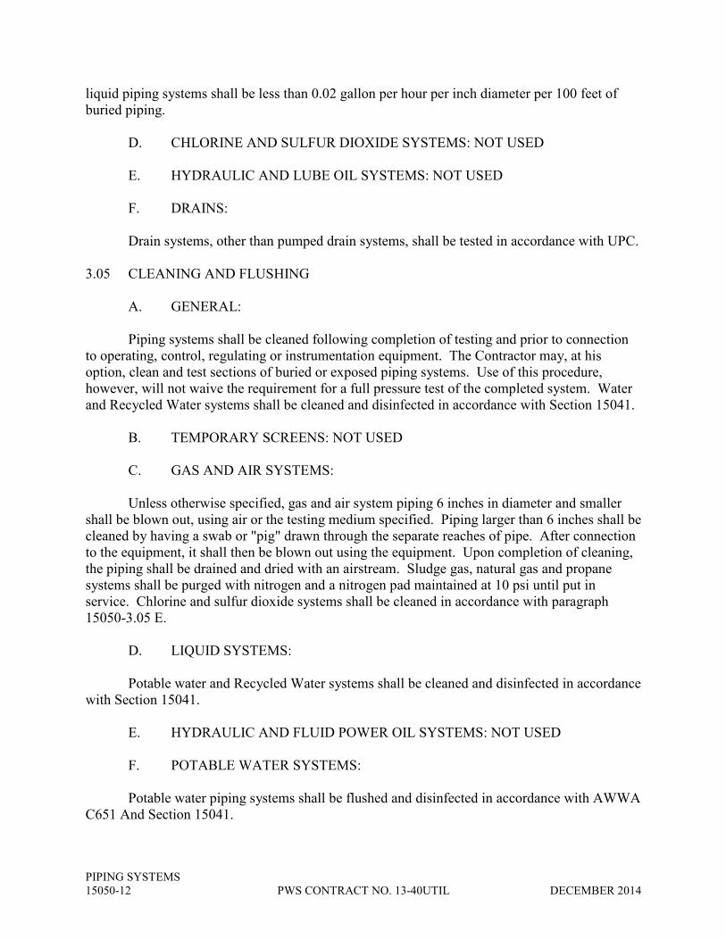
liquid piping systems shall be less than 0.02 gallon per hour per inch diameter per 100 feet of
buried piping.
D. CHLORINE AND SULFUR DIOXIDE SYSTEMS: NOT USED
E. HYDRAULIC AND LUBE OIL SYSTEMS: NOT USED
F. DRAINS:
Drain systems, other than pumped drain systems, shall be tested in accordance with UPC.
3.05 CLEANING AND FLUSHING
A. GENERAL:
Piping systems shall be cleaned following completion of testing and prior to connection
to operating, control, regulating or instrumentation equipment. The Contractor may, at his
option, clean and test sections of buried or exposed piping systems. Use of this procedure,
however, will not waive the requirement for a full pressure test of the completed system. Water
and Recycled Water systems shall be cleaned and disinfected in accordance with Section 15041.
B. TEMPORARY SCREENS: NOT USED
C. GAS AND AIR SYSTEMS:
Unless otherwise specified, gas and air system piping 6 inches in diameter and smaller
shall be blown out, using air or the testing medium specified. Piping larger than 6 inches shall be
cleaned by having a swab or "pig" drawn through the separate reaches of pipe. After connection
to the equipment, it shall then be blown out using the equipment. Upon completion of cleaning,
the piping shall be drained and dried with an airstream. Sludge gas, natural gas and propane
systems shall be purged with nitrogen and a nitrogen pad maintained at 10 psi until put in
service. Chlorine and sulfur dioxide systems shall be cleaned in accordance with paragraph
15050-3.05 E.
D. LIQUID SYSTEMS:
Potable water and Recycled Water systems shall be cleaned and disinfected in accordance
with Section 15041.
E. HYDRAULIC AND FLUID POWER OIL SYSTEMS: NOT USED
F. POTABLE WATER SYSTEMS:
Potable water piping systems shall be flushed and disinfected in accordance with AWWA
C651 And Section 15041.

PIPING SYSTEMS
DECEMBER 2014 PWS CONTRACT NO. 13-40UTIL 15050-13
3.06 CONNECTION TO EXISTING FACILITIES (WET TAPS AND CUT-IN
INSTALLATIONS)
Wet taps and Cut-ins shall be in accordance with Section 02146
3.07 PIPING SPECIFICATION SHEETS (PIPESPEC)
Piping and valves for groupings of similar plant processes or types of service lines are
specified on individual piping specification sheets (PIPESPEC). Piping services are grouped
according to the chemical and physical properties of the fluid conveyed and/or by the
temperature or pressure requirements. Each grouping of services (PIPESPEC) is identified by a
piping system number. Piping services specified in the PIPESPEC and on the drawings are
alphabetically arranged by designated service symbols as shown in Table A. Table A also
indicates the system number and fluid category.
Table A, Piping Services
Symbol Service System Category
1W Potable Water 7 Potable
2W Nonpotable Water 11 Nonpotable
CD Chemical Drain 25 Drain
CW Potable Water 7 Potable
DSF Diesel Fuel 18 Fuel Oil
D Drain 24 Drain
EE Engine Exhaust 31 Air
FA Foul Air 22 Air
IA Instrument Air 2 Air
PD Pumped Drainage 12 Wastewater
RA Return Air Air
RS Raw Sewage (Gravity) 12A Wastewater
Raw Sewage (Pressure) 12B Wastewater
RWR/RW Reclaimed Water 9 Reclaimed
S Sewer 12A Wastewater
SD Storm Drain 24 Drain
VP Petroleum Vent 18 Fuel Oil

PIPING SYSTEMS
15050-14 PWS CONTRACT NO. 13-40UTIL DECEMBER 2014
3.07 PIPING SPECIFICATION SHEETS--PIPESPEC
Piping Symbol/Service: IA--Instrument Air System--2
SA--Service Air
Test Requirements:
Medium: Ref. spec paragraph 15050-3.04 B.
Pressure: 200 psig
Duration: 120 minutes
Gasket Requirements:
Flange: Compressed gasketing consisting of organic fibers (Kevlar)
and neoprene binder
Push-on/Mech Cpl: N/A
Exposed Pipe and Valves:
(See drawings for pipe size and valve type)
(1/2" and smaller)
Pipe: Copper tube; ASTM B88, Type L, drawn. Ref. spec Section
15057.
Conn; brass compression type.
Ftgs; brass compression type, Swagelok, Gyrolok, or equal.
OR (for all piping within and downstream of bubble panels)
Stainless Steel: 316/316L pipe and fittings. Refer to Section
15067.
Conn: Screwed or welded
(3/4" thru 2")
Pipe: Copper tube; ASTM B88, Type L, drawn.
Conn; solder type with threaded adapters or valves.
Ftgs; wrought copper or bronze, ANSI B16.22.
OR (for all piping within and downstream of bubble panels)
Stainless Steel: 316/316L pipe and fittings. Refer to Section
15067.
Conn: Screwed or welded
(2" and smaller)
Valves: Ball; Jamesbury Fig. 351, Nibco T-580, or equal.
Globe; Crane 7TF or 17TF, Lunkenheimer 123 or 214, or
equal.
Lift check; Lunkenheimer 1616, Crane 366E, or equal.

PIPING SYSTEMS
DECEMBER 2014 PWS CONTRACT NO. 13-40UTIL 15050-15
3.07 PIPING SPECIFICATION SHEETS--PIPESPEC
Piping Symbol/Service: 2 (continued)
(2 1/2" thru 6")
Pipe: Steel; ASTM A53, ERW, Grade B, black, no lining. Ref.
spec Section 15061.
Conn; butt weld, flanged for valves.
Ftgs; steel, ASTM A234, ANSI B16.9; ends to match pipe.
Valves: Ball; Jamesbury 5150-31-2200TT, Nibco F-510, or equal.
Check; Ported plate style designed for use with pulsating
flow; Hoerbiger Depend-A-Check or Compact-A-Check,
Dienes Type DL-RF, or equal.
Buried and Encased Pipe and Valves:
(See drawings for pipe size and valve type. Omit coatings on encased pipe.)
(2" and smaller)
Pipe: Copper tube; ASTM B88, Type K, annealed or drawn.
Conn; solder type.
Ftgs; wrought copper or bronze, ANSI B16.22.
Valves: Ball; same as exposed with extension stem and valve box.
(2 1/2" thru 6")
Pipe: Steel; same as exposed with polyethylene tape coating. Field
application of coating to all couplings. Ref. spec Section
15061.
Conn; same as exposed with coating.
Ftgs; same as exposed with coating.
Valves: Ball; same as exposed with extension stem and valve box.
Coating M-1 per spec Section 09900.
Remarks:
Pipe materials for immersed service air piping shall be:
(2" and smaller)
Pipe: Stainless steel; ASTM A312, Schedule 40S. Ref. spec
Section 15067.
Conn; threaded, ANSI B1.20.1.
Ftgs; ASTM A403, material, ends and wall thickness to
match pipe.

PIPING SYSTEMS
15050-16 PWS CONTRACT NO. 13-40UTIL DECEMBER 2014
3.07 PIPING SPECIFICATION SHEETS--PIPESPEC
Piping Symbol/Service System--7
1W--Potable Water (may also be called CW-City Water)
HW – Potable Hot Water
Test Requirements: Medium: Water; ref. spec paragraph 15050-3.04 C. Pressure: 150 psig Duration: 60 minutes Gasket Requirements: Flange: Compressed gasketing consisting of organic fibers (Kevlar)
and neoprene binder Push-on/Mech Cpl: EPDM Exposed Pipe and Valves (INDOORS): (See drawings for pipe size and valve type. See Remarks for insulation requirements.) (3" and smaller) Pipe: When not otherwise indicated: Copper tube; ASTM B88, Type L, drawn. Ref. spec Section
15057. Conn; solder type with threaded or flanged adapters for
valves. Ftgs; wrought copper or bronze, ANSI B16.22. Insullation: See Remarks Between seal water panel and pumps: Stainless Steel: 316/316L pipe and fittings. Refer to Section
15067. Conn: Screwed or welded (2" and smaller) Valves: Ball; Jamesbury Fig. 351, Nibco T-580, or equal. Globe; Crane 7TF or 17TF, Lunkenheimer 123 or 214, or
equal. Swing check; Crane 137, Lunkenheimer 230, or equal.

PIPING SYSTEMS
DECEMBER 2014 PWS CONTRACT NO. 13-40UTIL 15050-17
3.07 PIPING SPECIFICATION SHEETS--PIPESPEC
Piping Symbol/Service: 7 (continued)
(2 1/2" and larger)
Valves: Butterfly; ref. spec Section 15103. Substitute Type B on
2-1/2-inch lines.
Swing check; spring loaded per spec Section 15118. Exposed Pipe and Valves (OUTDOORS): (See drawings for pipe size and valve type. See Remarks for insulation requirements.) (3" and smaller)
Pipe: PVC; ASTM D1784, Class 12454-B, NSF certified, ASTM
D1785, Sch. 80. Ref. spec Section 15064.
Conn; plain end; solvent weld.
Ftgs; PVC, Sch. 80, socket type.
Valves: Ball; PVC, true union, socket type, Chemtrol Tru Block TU
Series, Asahi/ America Duo Bloc TU Series, GSR TU Series,
or equal, with PTFE seats and Viton O-rings.
Diaphragm; PVC body, PTFE diaphragm, Chemtrol Series
PD, Posacon 677, Asahi/ America, or equal.
Buried and Encased Pipe and Valves:
(See drawings for pipe size and valve type. Omit coating on
encased pipe. See Remarks for insulation requirements.)
(3" and smaller)
Pipe: PVC; ASTM D1784, Class 12454-B, NSF certified, ASTM
D1785, Sch. 80. Ref. spec Section 15064.
Conn; plain end; solvent weld.
Ftgs; PVC, Sch. 80, socket type.
Valves: Ball; PVC, true union, socket type, Chemtrol Tru Block TU
Series, Asahi/ America Duo Bloc TU Series, GSR TU Series,
or equal, with PTFE seats and Viton O-rings.
Diaphragm; PVC body, PTFE diaphragm, Chemtrol Series
PD, Posacon 677, Asahi/ America, or equal.
(4" to 12”)
Pipe: PVC; per AWWA C900, DR 14. Ref. spec Section 15064.
Restrained push-on rubber gasket joint. Flanged adapters for
valves.
Ftgs; ductile iron per spec Section 15062; coating, lining and
ends to match pipe.

PIPING SYSTEMS
15050-18 PWS CONTRACT NO. 13-40UTIL DECEMBER 2014
3.07 PIPING SPECIFICATION SHEETS--PIPESPEC
Piping Symbol/Service: 7 (continued)
Valves: Gate, Resilient Seated; ref. spec Section 15102, with exten-
sion stem and valve box. Coating M-1 per spec Section
09900.
Remarks:
1. Manual air vents shall be provided at the high points and drains provided at the low points
of each reach of pipeline as specified in paragraph 15095-3.03.
2. Exposed piping at the Electrical/Generator Building shall be insulated per Section 15250.
3. Systems shall be disinfected per City requirements.
4. Hot water piping shall be insulated.

PIPING SYSTEMS
DECEMBER 2014 PWS CONTRACT NO. 13-40UTIL 15050-19
3.07 PIPING SPECIFICATION SHEETS--PIPESPEC
Piping Symbol/Service: RWR--Reclaimed Water System--9
RW -Recycled Water
Test Requirements:
Medium: Water; ref. spec paragraph 15050-3.04 C.
Pressure: (200) psig
Duration: 4 hours
Gasket Requirements:
Flange: Compressed gasketing consisting of organic fibers (Kevlar)
and neoprene binder
Push-on/Mech Cpl: Nitrile or Neoprene
Exposed Pipe and Valves:
(See drawings for pipe size and valve type)
(3" and smaller)
Pipe: Steel; ASTM A53, galvanized. Ref. spec Section 15061.
Conn; taper threaded, ANSI B1.20.1. Flanged adapters for
2-1/2 inch, 3 inch valves.
Ftgs; malleable iron, ASTM A197, ANSI B16.3, Class 150,
galvanized.
(2" and smaller)
Valves: Ball; Jamesbury Fig. 351, Nibco T-580, or equal.
Globe; Crane 7TF or 17TF, Lunkenheimer 123 or 214, or
equal.
Swing check; Crane 137, Lunkenheimer 230, or equal.
(4" thru 8")
Pipe: Steel; ASTM A53, ERW, Grade B, black, with cement
mortar lining. Ref. spec Section 15061.
Conn; grooved mech pipe coupling or flanged.
Ftgs; malleable iron, ductile iron, or steel, per spec Section
15061; ends and lining to match pipe.
(2 1/2" thru 8")
Valves: Butterfly; Ref. spec Section 15103. Swing check;
spring loaded per spec Section 15118.

PIPING SYSTEMS
15050-20 PWS CONTRACT NO. 13-40UTIL DECEMBER 2014
3.07 PIPING SPECIFICATION SHEETS--PIPESPEC
Piping Symbol/Service: 9 (continued)
(10" thru 24")
Pipe: Steel; same as 8 inch, or AWWA C200, minimum 3/8 inch
thick unless otherwise specified, with cement mortar lining.
Ref. spec Section 15061.
Conn; same as 8 inch. See Remarks.
Ftgs; steel, ASTM A234, or fabricated steel, AWWA C208.
Lining and ends to match pipe.
Valves: Butterfly; ref. spec Section 15103.
Swing check; spring loaded per spec Section 15118.
Buried and Encased Pipe and Valves:
(See drawings for pipe size and valve type. Omit coating on concrete encased pipe.)
(3" and smaller)
Pipe: PVC; ASTM D1784, Class 12454-B, NSF certified, ASTM
D1785, Sch. 80. Ref. spec Section 15064. Provide magnetic
tracer tape. See Remarks.
Conn; plain end; solvent weld with threaded or flanged
adapters for valves.
Ftgs; PVC, Sch. 80, socket weld.
Valves: Gate; ref. spec Section 15101, with extension stem and valve
box. Coating M-1 per spec Section 09900.
(4" to 12")
Pipe: PVC; per AWWA C900, DR 14. Conn; restrained
push-on rubber gasket joint. Flanged adapters for valves.
Steel; where identified on drawings, ASTM A53, ERW,
Grade B, black, with cement mortar lining or AWWA C200
with cement mortar lining and coating, Ref. spec Section
15061.
Ftgs; ductile iron per spec Section 15062; ends to match pipe.
Valves:
Gate; Resilient seated. ref. spec Section 15102, with
extension stem and valve box. Coating M-1 per spec Section
09900.

PIPING SYSTEMS
DECEMBER 2014 PWS CONTRACT NO. 13-40UTIL 15050-21
3.07 PIPING SPECIFICATION SHEETS--PIPESPEC
Piping Symbol/Service: 9 (continued)
(14" to 48")
Pipe: PVC; per AWWA C905, DR 18. Ref. spec Section 15064.
Conn; Push-on rubber gasket joint. Flanged adapters for
valves.
OR, where indicated on the drawings,
Steel, same as 4” to 12”, Ref. spec Section 15061.
Ftgs; Steel per Section 15061 Steel coating, lining and ends
to match pipe.
Valves: Gate; Resilient seated pipe 16” or smaller, ref. spec Section
15102, with extension stem and valve box
Butterfly; Resilient seated. 18” or larger, ref. spec Section
15103, with extension stem and valve box.
Coating M-1 per spec Section 09900.
Remarks:
1. Manual air vents shall be provided at the high points and drains provided at the low points
of each reach of pipeline as specified in paragraph 15095-3.03.
2. Irrigation piping shall be per Landscape drawings.
3. All piping shall meet City standards for recycled and reclaimed water.

PIPING SYSTEMS
15050-22 PWS CONTRACT NO. 13-40UTIL DECEMBER 2014
3.07 PIPING SPECIFICATION SHEETS--PIPESPEC
Piping Symbol/Service: 2W--Nonpotable City Water System--11
Test Requirements:
Medium: Water; ref. spec paragraph 15050-3.04 C.
Pressure: 150 psig
Duration: 60 minutes
Gasket Requirements:
Flange: Compressed gasketing consisting of organic fibers (Kevlar)
and neoprene binder
Push-on/Mech Cpl: Nitrile or Neoprene
Exposed Pipe and Valves:
(See drawings for pipe size and valve type)
(2" and smaller)
Pipe: Steel; ASTM A53, galvanized. Ref. spec Section 15061.
Conn; taper threaded, ANSI B1.20.1.
Ftgs; malleable iron, ASTM A197, ANSI B16.3, Class 150,
galvanized. Ends to match pipe.
Valves: Ball; Jamesbury Fig. 351, Nibco T-580, or equal.
Globe; Crane 7TF or 17TF, Lunkenheimer 123 or 214, or
equal.
Swing check; Crane 137, Lunkenheimer 230, or equal.
(2" and smaller)(inside the wet well)
Pipe: Stainless steel; ASTM A312, Schedule 40S. Ref. spec
Section 15067.
Conn; threaded, ANSI B1.20.1.
Ftgs; ASTM A403, material, ends and wall thickness to
match pipe.
Valves: Ball or Globe as shown; 316 SS; ends to match pipe.
(2 1/2" thru 8")
Pipe: Steel; ASTM A53, ERW, Grade B, black, no lining. Ref.
spec Section 15061.
Conn; butt weld, grooved mech pipe coupling or flanged.
Ftgs; malleable iron, ductile iron, or steel per spec Section
15061; ends to match pipe.

PIPING SYSTEMS
DECEMBER 2014 PWS CONTRACT NO. 13-40UTIL 15050-23
3.07 PIPING SPECIFICATION SHEETS--PIPESPEC
Piping Symbol/Service: 11 (continued)
Valves: Butterfly; ref. spec Section 15103. Substitute Type B on
2-1/2-inch lines.
Swing check; spring loaded per spec Section 15118.
Buried and Encased Pipe and Valves:
(See drawings for pipe size and valve type. Omit coating on encased pipe.)
(3" and smaller)
Pipe: PVC; ASTM D1784, Class 12454-B, NSF certified, ASTM
D1785, Sch. 80. Ref. spec Section 15064. Provide magnetic
tracer tape. COLOR SHALL BE PURPLE
Conn; plain end; solvent weld with threaded or flanged
adapters for valves.
Ftgs; PVC, Sch. 80, socket weld.
Valves: Ball; Jamesbury Fig. 351, Nibco T-580, or equal.
(4" thru 12")
Pipe:
PVC; per AWWA C900, DR 14. Ref. spec Section 15064.
COLOR SHALL BE PURPLE
Conn; grooved end or restrained push-on rubber gasket joint.
Flanged adapters for valves.
Ftgs; ductile iron per spec Section 15062; coating, lining and
ends to match pipe.
Valves:
Gate; Resilient seated. ref. spec Section 15102, with
extension stem and valve box. Coating M-1 per spec Section
09900.

PIPING SYSTEMS
15050-24 PWS CONTRACT NO. 13-40UTIL DECEMBER 2014
3.07 PIPING SPECIFICATION SHEETS--PIPESPEC
Piping Symbol/Service: 11 (continued)
Remarks:
1. Manual air vents shall be provided at the high points and drains provided at the low points
of each reach of pipeline as specified in paragraph 15095-3.03.

PIPING SYSTEMS
DECEMBER 2014 PWS CONTRACT NO. 13-40UTIL 15050-25
3.07 PIPING SPECIFICATION SHEETS--PIPESPEC Piping Symbol/Service: RS--Raw Sewage (GRAVITY) System—12A S- Sewer (from Restroom) Test Requirements: 40” and smaller pipe: water, 15043, 15063 & SSPWC 3.06-
1.4. 42” and larger pipe: see Sections 15043, 15059 or 15072 Gasket Requirements: Flange: Compressed gasketing consisting of organic fibers (Kevlar)
and neoprene binder Push-on/Mech Cpl: Nitrile or Neoprene unless otherwise indicated Exposed Pipe and Valves: (See drawings for pipe size, material and valve type) (Same as Buried and Encased) Buried and Encased Pipe and Valves: (See drawings for pipe size and valve type. Omit coating on encased pipe.) Restroom Drainage: Pipe: Cast iron soil pipe (CISP); ASTM A74. Conn; service hub and spigot compression type or hubless
cast iron sanitary system per CISPI 301. Ftgs; CISP, ASTM A74, joint options to match pipe. Valves: None Gravity Sewer: (40” and smaller) Pipe: PVC Gravity Sewer, Ref. spec 15063. Conn; ASTM F477, elastomeric gaskets. Ftgs; fabricated fittings as specified. OR (for the Lift Station discharge only) Pipe: Ductile iron; AWWA C151. Ref. spec Section 15062.
Fusion epoxy lining per spec Section 15061. Conn; flanges, push-on, or mechanical joint as indicated on
the drawings. Ftgs; ductile iron per spec Section 15062; lining and ends to
match pipe. Coat with tape wrap per spec Section 09900 System M-1.
Valves: None.

PIPING SYSTEMS
15050-26 PWS CONTRACT NO. 13-40UTIL DECEMBER 2014
3.07 PIPING SPECIFICATION SHEETS--PIPESPEC
Piping Symbol/Service: 12A (continued)
(42” and larger) Open-Cut Installation: See System 12A Note 1
Pipe: Fiberglass Reinforced Polymer Mortar Pipe per spec Section
15059.
Conn; ASTM D4161, elastomeric gaskets
Ftgs; FRPM or CCFRPM Tee Base Manholes and fabricated
fittings as specified in the drawings
OR
Pipe Steel Reinforced Polymer Concrete Pipe, per spec Section
15072.
Conn; ASTM C443 and ASTM D4161, elastomeric gaskets
Ftgs; polymer or concrete manhole as specified in the
drawings;
Valves: None.
Microtunnel Installation:
Pipe: Fiberglass Reinforced Polymer Mortar Pipe per spec Section
15059.
Conn; ASTM D4161, elastomeric gaskets
Ftgs; FRPM or CCFRPM Tee Base Manholes and fabricated
fittings as specified in the drawings
OR
Pipe Steel Reinforced Polymer Concrete Pipe, per spec Section
15072.
Conn; ASTM C443 and ASTM D4161, elastomeric gaskets
Ftgs; polymer or concrete manhole as specified in the
drawings;
Valves: None.

PIPING SYSTEMS
DECEMBER 2014 PWS CONTRACT NO. 13-40UTIL 15050-27
3.07 PIPING SPECIFICATION SHEETS--PIPESPEC
Piping Symbol/Service: 12A (continued)
NOTE: DESIGN FOR GRAVITY PIPE LARGER THAN 42 INCHES HAS BEEN BASED ON
USING FRPM OR CCFRPM PIPE..
Flow Diversion:
(42”)
Pipe: Reinforced Concrete Pipe, Ref. spec 15056.
Conn; ASTM C443, elastomeric gaskets.
Ftgs; as specified.

PIPING SYSTEMS
15050-28 PWS CONTRACT NO. 13-40UTIL DECEMBER 2014
3.07 PIPING SPECIFICATION SHEETS--PIPESPEC
Piping Symbol/Service: PD--Pumped Drainage System—12B
RS--Raw Sewage (PRESSURE) (Remark 2)
Test Requirements:
Medium: Water; ref. spec paragraph 15050-3.04 C.
Pressure: 30 psig
Duration: 120 minutes
Gasket Requirements:
Flange: Compressed gasketing consisting of organic fibers (Kevlar)
and neoprene binder
Push-on/Mech Cpl: Nitrile or Neoprene
Exposed Pipe and Valves:
(See drawings for pipe size, material and valve type)
Force Main Pipe, and Lift Station Pump Suction Pipe:
(2" and smaller)
Pipe: Steel; ASTM A53, galvanized. Ref. spec Section 15061.
Conn; taper threaded, ANSI B1.20.1.
Ftgs; malleable iron, ASTM A197, ANSI B16.3, Class 150,
galvanized.
Valves: Eccentric plug; per spec Section 15110. Install valve with
seat upstream.
Swing check; Lunkenheimer 230, Crane 137, or equal.
(2 1/2" thru 8")
Pipe: Steel; ASTM A53 ERW, Grade B, black, no lining. Ref.
spec Section 15061.
Conn; butt weld, or flanged.
Ftgs; steel per spec Section 15061; ends to match pipe.
Valves: Eccentric plug; per spec Section 15110. Install valve with
seat upstream.
Swing check; spring loaded per spec Section 15118.

PIPING SYSTEMS
DECEMBER 2014 PWS CONTRACT NO. 13-40UTIL 15050-29
3.07 PIPING SPECIFICATION SHEETS--PIPESPEC
Piping Symbol/Service: 12B (continued)
(10” and larger)
Pipe: Steel; AWWA C200, 1/4 inch thick, with fusion epoxy
lining. Ref. spec Section 15061. See Remarks.
Conn; same as 8 inch. See Remarks.
Ftgs; steel, ASTM A234, or fabricated steel, AWWA C208.
Lining and ends to match pipe.
See Remarks.
Valves: As indicated on the drawings; valve types are not
interchangeable.
Eccentric Plug; per spec Section 15110 with dielectric
isolation.
Ball: per spec Section 15129 with dielectric isolation.
Swing check; spring loaded per spec Section 15118.
Wastewater Air
Release & Vacuum Valves: per spec Section 15166.
Lift Station Pump Discharge Pipe:
(2 ½" and smaller): Stainless Steel, ASTM A312, Ref. spec Section 15067
Conn; taper threaded
Ftgs; ASTM A403
(3" and larger): Stainless steel; ASTM A778. Schedule 10. Ref. spec Section
15067.
Conn; butt weld or flanged, couplings where indicated.
Ftgs; ASTM A774, material, ends and wall thickness to
match pipe.
Valves: As indicated on the drawings; valve types are NOT
interchangeable.
Eccentric Plug; per spec Section 15110 with dielectric
isolation.
Ball: per spec Section 15129 with dielectric isolation.
Swing check; spring loaded per spec Section 15118.

PIPING SYSTEMS
15050-30 PWS CONTRACT NO. 13-40UTIL DECEMBER 2014
3.07 PIPING SPECIFICATION SHEETS--PIPESPEC
Piping Symbol/Service: 12B (continued)
Buried and Encased Pipe and Valves:
(See drawings for pipe size and valve type. Omit coating on encased pipe.)
Force Main:
Pipe: HDPE; AWWA C906, Ref. spec Section 15065.
Conn; butt-fusion per ASTM D2657.
Ftgs; Fittings shall conform to the applicable requirements of
AWWA C906 for the joining methods specified in paragraph
15065-3.02 B
OR
(4" and larger where indicated
on drawings near lift station)
Pipe: Ductile iron; AWWA C151. Ref. spec Section 15062.
Ceramic epoxy lined per Section 09900 and Section 15062.
Conn; mechanical joint or push-on rubber gasket joint;
restrained .
Ftgs; ductile iron, per spec Section 15062; coating, lining and
ends to match pipe. Coat with tape wrap per Section 09900
System M-1.
Wall penetration to ground: Steel; same as exposed. Coat with tape wrap per
Section 09900 System M-1.
Valves: Eccentric Plug; per spec Section 15110.
Remarks:
1. Manual air vents shall be provided at the high points and drains provided at the low points
of each reach of pipeline as specified in paragraph 15095-3.03.
2. System 12B applies to suction and discharge piping for all pumps (even if not under
pressure) and other smaller diameter piping associated with the suction and discharge
piping. In addition to the specified fusion bonded epoxy lining, pump suction piping within
the wet well and at the start of encasement in the wet well wall shall be coated with fusion
bonded epoxy specified in Section 15061. Exterior fusion epoxy coating shall extend into
concrete one inch to ensure corrosion protection. Coating shall be discontinued in most of
the wall to improve bonding between concrete and pipe.

PIPING SYSTEMS
DECEMBER 2014 PWS CONTRACT NO. 13-40UTIL 15050-31
3.07 PIPING SPECIFICATION SHEETS--PIPESPEC
Piping Symbol/Service: 12B (continued)
3. Buried and encased couplings shall be fusion epoxy lined and coated per Specification
Section 09961; tape wrap per Section 09900 System M-1.
4. Submerged and encased pump suction piping 10” and larger shall be 3/8-inch thick steel.

PIPING SYSTEMS
15050-32 PWS CONTRACT NO. 13-40UTIL DECEMBER 2014
3.06 PIPING SPECIFICATION SHEETS--PIPESPEC
Piping Symbol/Service: DSF--Diesel Fuel System--18
VP--Petroleum Vent
Test Requirements:
Medium: Fuel oil; ref. spec paragraph 15050-3.04 E.
Pressure: 150 psig (pressure piping)
5 psig (nonpressure piping)
Duration: 60 minutes
Gasket Requirements:
Flange: Compressed gasketing consisting of organic fibers (Kevlar)
and neoprene binder
Exposed Pipe and Valves:
(See drawings for pipe size and valve type)
(2" and smaller)
Pipe: Steel; ASTM A106, seamless, Grade B, black, pickled. Ref.
spec Section 15061.
Conn; threaded or socket weld with threaded adapters for
valves.
Ftgs; forged steel, ASTM A105, ANSI B16.11, pressure
Class 3000, pickled.
Double Containment: Required for fill line between fill
station and fuel tank. See spec Section 15073.
Valves: Lubricated plug; cast iron, PTFE coated plug, Nordstrom Fig.
142, Walworth Fig. 1796, or equal.
Lift check; Crane 27TF, Lunkenheimer 231, or equal.
Remarks:
1. The cleaning (pickling) solution used shall comply with Mil-H-13528B. Immediately
following pickling and rinsing procedures, steel pipe and fittings shall be coated inside and
outside with a rust and corrosion preventative system, and the ends sealed to prevent the
entry of dirt.

PIPING SYSTEMS
DECEMBER 2014 PWS CONTRACT NO. 13-40UTIL 15050-33
3.07 PIPING SPECIFICATION SHEETS--PIPESPEC
Piping Symbol/Service: FA--Foul Air System--22
Test Requirements:
Medium: Air; ref. spec paragraph 15050-3.04 B.
Pressure: 3 psig
Duration: 60 minutes
Gasket Requirements, 16” and smaller:
Flange: Gylon gasketing, Garlock style 3504
Push-on/Mech Cpl: PTFE
Exposed Pipe and Valves:
(See drawings for pipe size and valve type)
(6" and smaller)
Pipe: PVC; ASTM D1784, Class 12454-B, ASTM D2665, Sch.80.
Ref. spec Section 15064.
Conn; plain end, solvent weld.
Ftgs; PVC, socket type, ASTM D2467.
Valves: Ball; PVC Chemtrol Tru Bloc TU Series, Asahi/America
Duo Bloc TU Series, GSR TU Series, or equal, with PTFE
seats and EPDM 0-rings.
(8" and larger) FRP Ductwork; ref. spec Section 13234
Valves: Butterfly; ref. spec Section 15103.
Buried and Encased Pipe and Valves: (See drawings for pipe size and valve type)
Pipe: HDPE; AWWA C906, Ref. spec Section 15065.
Conn; butt-fusion per ASTM D2657.
Ftgs; Fittings shall conform to the applicable requirements of
AWWA C906 for the joining methods specified in paragraph
15065-3.02 B

PIPING SYSTEMS
15050-34 PWS CONTRACT NO. 13-40UTIL DECEMBER 2014
3.07 PIPING SPECIFICATION SHEETS--PIPESPEC
Piping Symbol/Service: 22 (continued)
Valves: None
Remarks: None

PIPING SYSTEMS
DECEMBER 2014 PWS CONTRACT NO. 13-40UTIL 15050-35
3.07 PIPING SPECIFICATION SHEETS--PIPESPEC
Piping Symbol/Service: D—Drain System--24
RWP--Rainwater Pipe
SD--Storm Drain
V--Vent
Test Requirements:
Medium: In accordance with Section 712, Uniform Plumbing Code.
Pressure: In accordance with Section 712, Uniform Plumbing Code.
Duration: In accordance with Section 712, Uniform Plumbing Code.
RCP, 14” and larger: per Section 15056
Gasket Requirements:
Flange: Compressed gasketing consisting of organic fibers (Kevlar)
and neoprene binder
Push-on/Mech Cpl: Nitrile or neoprene
Exposed Pipe and Valves:
(See drawings for pipe size.)
(3" and smaller)
Pipe: Steel; ASTM A53, galvanized. Ref. spec Section 15061.
Conn; taper threaded, ANSI B1.20.1.
Ftgs; cast iron, threaded drainage fittings, ASTM A126,
ANSI B16.12, galvanized.
Valves: None
(4" and larger)
Pipe: Ductile iron; AWWA C151. Ref. spec Section 15062.
Conn; flanged or mechanical.
Ftgs; ductile iron, per spec Section 15062; ends to match
pipe.
Valves: None
Buried and Encased Pipe and Valves
(See drawings for pipe size.)

PIPING SYSTEMS
15050-36 PWS CONTRACT NO. 13-40UTIL DECEMBER 2014
3.07 PIPING SPECIFICATION SHEETS--PIPESPEC
Piping Symbol/Service: 24 (continued)
(8" and smaller)
Pipe: PVC; ASTM D1784, Class 12454-B, ASTM D2665, Sch. 40.
Ref. spec Section 15063. Provide magnetic tracer tape.
Conn; plain end, solvent weld.
Ftgs; PVC, socket type, DWV, ASTM D2665.
Valves: None
(10" and 12")
Pipe: PVC; ASTM D3034, SDR 35. Provide magnetic tracer tape.
Conn; Push-on with nitrile gasket.
Ftgs; PVC or IPS cast iron; ends to match pipe.
Valves: None
(14" and larger)
Pipe: Reinforced concrete pipe (RCP); ref. spec Section 15056.
Conn; ASTM C443, rubber gasket type.
Ftgs; concrete manhole and drain inlets as specified on the
drawings.
Valves: None

PIPING SYSTEMS
DECEMBER 2014 PWS CONTRACT NO. 13-40UTIL 15050-37
3.07 PIPING SPECIFICATION SHEETS--PIPESPEC
Piping Symbol/Service: CD—Chemical, Condensate Drain System--25
VC--Chemical Vent
Test Requirements:
Medium: In accordance with Section 712, Uniform Plumbing Code.
Pressure: In accordance with Section 712, Uniform Plumbing Code.
Duration: In accordance with Section 712, Uniform Plumbing Code.
Gasket Requirements:
Flange: N/A
Push-on/Mech Cpl: N/A
Exposed Pipe and Valves:
(See drawings for pipe size and valve type)
(All sizes)
Pipe: PP; ASTM D4101, Sch. 40, flame retardant. Ref. spec
Section 15064.
Conn; ref. spec Section 15064.
Ftgs; PP, socket type coil fused DWV. Ref. spec Section
15064.
Valves: None
Buried and Encased Pipe and Valves:
(See drawings for pipe size and valve type)
Pipe: PP; same as exposed. Provide magnetic tracer tape.
Conn; ref. spec Section 15064.
Ftgs; same as exposed.
Valves: None
Remarks:

PIPING SYSTEMS
15050-38 PWS CONTRACT NO. 13-40UTIL DECEMBER 2014
3.07 PIPING SPECIFICATION SHEETS--PIPESPEC
Piping Symbol/Service EE--Engine Exhaust System--31
Test Requirements:
Medium: None
Pressure: None
Duration: None
Gasket Requirements:
Flange: See Remarks
Push-on/Mech Cpl: N/A
Exposed Pipe and Valves:
(See drawings for pipe size)
All Pipe: Carbon Steel; Schedule 40; Type 321 or 316seamless,
welded.
Conn; butt weld, flanged for equipment connections.
Ftgs; ASTM A403, material, thickness, and end connections
to match pipe.
Remarks:
1. Pipe and fittings shall be insulated with Thermo rap, see Section 16232.
2. Flange gasket shall be flat, full-face, graphoil suitable for temperatures to 1200 degrees F.
** END OF SECTION **

REINFORCED CONCRETE PIPE
DECEMBER 2014 PWS CONTRACT NO. 13-40UTIL 15056-1
SECTION 15056
REINFORCED CONCRETE PIPE
PART 1--GENERAL
1.01 DESCRIPTION
A. SCOPE:
This section specifies reinforced concrete pipe (RCP), gaskets, and accessories for open cut
installation of storm drains and gravity sewer as specified. This section also contains specifications
for manhole tees/elbows and other specialized pipe sections together with fittings and
appurtenances.
Perform the work specified to provide reinforced concrete pipe (RCP) complete and in place
including miscellaneous fittings and specials required for proper completion of the Work.
RCP for sanitary sewer applications shall be provided with PVC liners for protection
against corrosion. Liners shall be locked into the concrete by means of tee-shaped extensions with
joint overlaps welded, providing a continuous protective barrier against corrosion. Joint overlaps
shall extend a minimum of ½” from the near joint edge and be sealed with a 1” weld strip.
Comply with applicable provisions of the Supplemental Provisions, CMWD Standard
Specifications, and SSPWC except as otherwise shown and specified.
Alternate pipe material designs shall be subject to approval by the CONSTRUCTION
MANAGER prior to procurement of the pipe to be provided by the CONTRACTOR.
B. REQUIREMENTS:
1. DESIGN RESPONSIBILITY: The design and layout of pipe shall meet
the service conditions and the criteria specified in this Section and as shown on the Plans are the
responsibility of the Contractor. This design shall be performed by or under the supervision of a
Professional Engineer licensed by the State of California. The Contractor shall submit design
calculations for pipe reinforcing and wall thickness, class or D-Load demonstrating that the pipe
is capable of sustaining the maximum stresses imposed during installation and service.
The calculations shall take into account dead loads, live loads such as traffic and
railroad, and any other loads which may be reasonably anticipated.
The calculations shall include trench details and materials proposed for bedding
and backfill in accordance with Section 02223 and Section 02200 for review and approval by the
Construction Manager.

REINFORCED CONCRETE PIPE
15056-2 PWS CONTRACT NO. 13-40UTIL DECEMBER 2014
C. DEFINITIONS:
1. PIPE JOINT: The area approximately 12 inches each way from the
centerline of the visible gap between pipe lengths.
2. PIPE LENGTH: The pipe between two joints; part of a pipe section.
3. PIPE SECTION: The reach of pipeline between two successive manholes.
1.02 QUALITY ASSURANCE
A. REFERENCES:
This section contains references to the following documents. They are a part of this section
as specified and modified. Where a referenced document contains references to other standards,
those documents are included as references under this section as if referenced directly. In the event
of conflict between the requirements of this section and those of the listed documents, the
requirements of this section shall prevail.
Unless otherwise specified, references to documents shall mean the documents in effect
at the time of Advertisement for Bids or Invitation to Bid (or on the effective date of the
Agreement if there were no Bids). If referenced documents have been discontinued by the
issuing organization, references to those documents shall mean the replacement documents
issued or otherwise identified by that organization or, if there are no replacement documents, the
last version of the document before it was discontinued. Where document dates are given in the
following listing, references to those documents shall mean the specific document version
associated with that date, regardless of whether the document has been superseded by a version
with a later date, discontinued or replaced.
Reference Title
ACI 318 Building Code Requirements for Structural Concrete
ASTM C14 Standard Specification for Concrete Sewer, Storm Drain, and
Culvert Pipe
ASTM C33 Standard Specification for Concrete Aggregate
ASTM C76 Reinforced Concrete Culvert, Storm Drain and Sewer Pipe
ASTM C114 Test Methods for Chemical Analysis of Hydraulic Cement
ASTM C139 Concrete Masonry Units for Construction of Catch Basins and
Manholes
ASTM C150 Standard Specification for Portland Cement
ASTM C289 Test Methods for Potential Alkali-Silica Reactivity of
Aggregates (Chemical Method)

REINFORCED CONCRETE PIPE
DECEMBER 2014 PWS CONTRACT NO. 13-40UTIL 15056-3
Reference Title
ASTM C 361 Standard Specification for Reinforced Concrete Low-Head
Pressure Pipe
ASTM C443 Joints for Circular Concrete Sewer and Culvert Pipe, Using
Rubber Gaskets
ASTM C478 Precast Reinforced Concrete Manhole Sections
ASTM C497 Testing Concrete Pipe, Sections, or Tile
ASTM C 506
(AASHTO M 206)
Standard Specification for Reinforced Concrete Arch Culvert,
Storm Drain, and Sewer Pipe
ASTM C655 Reinforced Concrete D-Load Culvert, Storm Drain and Sewer
Pipe
ASTM C 1433 Standard Specification for Precast Reinforced Concrete Box
Sections for Culverts, Storm Drains, and Sewers
ASTM D412 Test Method for Vulcanized Rubber and Thermoplastic
Rubbers and Thermoplastic Elastomers - Tension
ASTM D471 Test Method for Rubber Property – Effects of Liquid
ASTM D573 Test Method for Rubber – Deterioration in an Air Oven
ASTM D1149 Test Method for Rubber Deterioration - Surface Ozone
Cracking in a Chamber
ASTM D1171 Test Method for Rubber Deterioration - Surface Ozone
Cracking Outdoors or Chamber (Triangular Specimens)
ASTM D2240 Test Method for Rubber Property – Durometer Hardness
AWWA C302 Reinforced Concrete Pressure Pipe Non-Cylinder Type for
Water and Other Liquids
SSPWC Standard Specification for Public Works Construction
“Greenbook”, latest edition.
B. FACTORY INSPECTION AND TESTING:
One percent of the total number of pipes, with a minimum of three pipe lengths, of each
class, size and wall type shall be tested unless otherwise specified. Materials used in the
manufacture of the pipe shall be tested in accordance with the requirements of the applicable
referenced standards.

REINFORCED CONCRETE PIPE
15056-4 PWS CONTRACT NO. 13-40UTIL DECEMBER 2014
The CONTRACTOR shall perform said material tests at no additional cost to the OWNER.
The CONSTRUCTION MANAGER will witness all testing conducted by the CONTRACTOR;
provided, that the CONTRACTOR's schedule is not delayed for the convenience of the
CONSTRUCTION MANAGER. In addition to those tests specifically required, the
CONSTRUCTION MANAGER may request additional samples of any material for testing by the
OWNER. The additional samples shall be furnished at no additional cost to the OWNER. The
Construction Manager shall be notified of the place and time of testing 1 week prior to the
commencement of testing.
If any tested pipe should fail, two additional pipes shall be tested. Failure of any of the
additional pipe so tested shall be cause for the rejection of that lot of manufactured pipe.
1. CONCRETE COMPRESSION TESTS: Compression tests shall be as
specified in ASTM C76, Section 11.4.1.
2. D-LOAD TESTS: All pipe shall be subject to a D-Load test at the
manufacturer's plant. Pipe shall be tested in accordance with ASTM C76, Section 11.3 and
ASTM C497. Loads used for testing shall be the load to produce the 0.01-inch crack or the
design test load, whichever is less.
3. HYDROSTATIC TEST: Pipes shall be subjected to a hydrostatic test
made by applying suitable bulkheads at each end of the pipe and filling the pipe with water. At
the CONTRACTOR's option, the pipe may be soaked under reduced pressure prior to application
of the test pressure. The presoaking period shall not exceed 48 hours.
Acceptance hydrostatic tests shall be made at 15 psi internal pressure. The pipe
shall withstand the test pressure prescribed above for at least 20 minutes without cracking and
with no leakage appearing on the exterior surface. Moisture appearing on the surface of the pipe
in the form of damp spots or beads adhering to the surface will not be considered as leakage.
Slow forming beads of water that result in minor dripping which seal and dry up upon retesting
of the individual pipe unit under the prescribed test pressure will be considered acceptable.
Joints shall be subjected to hydrostatic test of the rubber gasket joints in
accordance with ASTM C 361 except that test pressure shall be a minimum of 5 psi.
4. PVC LINER PULL TEST: PVC liner shall be subject to a pull test
performed on a minimum of one lined pipe section for each 500 feet of pipe produced for the
project. The pull test of the liner shall be performed on a 1 inch to 3 inch length of liner. Unless
otherwise directed by the CONSTRUCTION MANAGER, the location of the tests shall be
within two feet of the end of the pipe which is up during manufacturing, except that a minimum
distance between the test location and the end of the sheet shall be 6 inches. In the event that one
pipe fails to withstand the required test, the manufacturer shall have the right to perform the test
on the liner in two other sections of pipe selected by the CONSTRUCTION MANAGER from
the same run as the original test pipe. If these two pipe sections successfully pass the test, the
remainder of the pipe on that run will be accepted. If tests on either of these pipes fail, the
remainder in that run will not be accepted until a pull test of the liner in each of the pipe sections

REINFORCED CONCRETE PIPE
DECEMBER 2014 PWS CONTRACT NO. 13-40UTIL 15056-5
has satisfactorily passed the test. Locations of the additional pull tests shall be determined by the
CONSTRUCTION MANAGER. The liner in the test pipe which passes the pull test may be
repaired by heat fusion welding and shipped to the project site.
The CONSTRUCTION MANAGER may require additional pull tests at no
additional cost to Owner if visual inspection reveals bumps or imperfections that may indicate
improper embedment of the liner.
1.03 SUBMITTALS
Submit Manufacturer's fabrication / design drawings. Drawings shall illustrate details of
wall thickness, pipe joint, joint gasket, and reinforcement. Reinforcement details shall include
the type of cage, the location of the cages in the pipe wall, the size and spacing of circumferential
and longitudinal reinforcing steel, and the cross-sectional area of reinforcing steel in each cage
per lineal foot of pipe. The gasket details shall include the diameter of the cross section and the
circumferential length. Submittals shall also include the design pipe size, D-load, cement type,
concrete strength and steel areas, and types and placement of reinforcement.
Layout drawings shall illustrate placement of each pipe length including fittings. Pipe
lengths and joints shall be identified with a numbering system.
A certified affidavit of compliance for all pipe and other products or materials furnished
under this Section, as specified in the reference standards and per Paragraph 1.02. B.
The Contractor shall provide certified copies of laboratory reports from the gasket
supplier indicating conformance with the specified requirements of Section 15075 and this
specification for each shipment of gaskets.
Design Calculations for wall thickness, pipe class and stiffness and product data as
necessary to fully describe all materials, components, and finished products and to show
conformance with the Contract Documents.
Submit PVC liner field joints shop drawings, installation procedures and testing
procedures for spark testing and joint weld testing including PVC liner manufacturer’s product
data.
Submit recommended repair methods and procedures for defects and damage to PVC
liner for RCP, structures and lined manholes including PVC liner manufacturer’s product data.
PART 2--PRODUCTS
2.01 CONCRETE MIXES
Concrete shall conform to the requirements of ASTM C 76 with the exceptions,
amendments and additions herein:

REINFORCED CONCRETE PIPE
15056-6 PWS CONTRACT NO. 13-40UTIL DECEMBER 2014
1. Cement shall be ASTM C150, Type II, and shall not contain more than 0.6
percent total alkali, or the sum of the sodium oxide (NaO,), and potassium
oxide (KO), calculated as sodium oxide (NaO + 0.658KO), determined in
accordance with ASTM C114.
2. Aggregates shall be nonreactive when tested in accordance with ASTM
C289 and evaluated in accordance with Appendix A-1 of ASTM C 33.
Aggregates found to be potentially reactive shall not be allowed unless
approved in writing by the CONSTRUCTION MANAGER.
3. Admixtures shall not be used unless specified or approved by the
Construction Manager.
4. Minimum 564 pounds of cement per cubic yard of concrete. Provide
maximum 4 inch slump.
2.02 FABRICATION
A. PIPE:
Pipe sections shall be made in normal lengths of at least 8 feet except where shorter
lengths are required to meet special conditions. Shorter lengths shall be used only where shown
on the Plans. To accommodate changes in alignment or curved alignments of the pipeline, pipe
ends may be beveled. Pipe ends shall not be beveled more than 5 degrees.
Pipe shall be vertically cast be in accordance with ASTM C 361 using a wet cast process
utilizing inner and outer forms, vibrated, and steam- or water-cured. Pipe manufactured by the
dry cast method is unacceptable.
Form oils or release agents shall not contain any material or substances as would
penetrate or otherwise retard concrete set at the formed surface. Concrete with a minimum slump
of 2-1/2 inches shall be used for manufacture of the pipe using the vertical cast process.
In no case shall pipe be less than that specified under ASTM C 76 provisions for Class
III, Walls "B", or "C." Wall".
B. REINFORCEMENT:
Minimum protective cover of concrete over the inner reinforcement cage shall be 1¼
inches.
Circumferential reinforcement shall have a minimum cover of 1¼ inch from the inside
surface and shall have a minimum cover of 1 ¼ inch from the outside surface of the pipe except
where additional cover is specified. Conditions permitting less cover shall not apply to the above
case. Reinforcing steel for each length of pipe shall be held in place throughout the casting
operation. Lift holes are not acceptable.

REINFORCED CONCRETE PIPE
DECEMBER 2014 PWS CONTRACT NO. 13-40UTIL 15056-7
C. JOINTS AND GASKETS:
Joint Design shall include provision for two rubber gaskets for all PVC lined pipe and all
pipe greater than or equal to 42-inches. Include two threaded test ports, with threaded PVC
plugs, one at the top of the pipe and one near the bottom of the pipe, for testing the annular space
between the two rubber gaskets.
Gaskets shall be synthetic rubber containing not less than 50 percent neoprene and shall
comply with the requirements of SSPWC Section 208-3 and ASTM C361.
D. FITTINGS:
Fittings may be fabricated from steel plate cement mortar-lined and coated, or from
mitered end concrete-pipe provided the maximum angle of any miter cut is 15 degrees and the
maximum deflection for a mitered bend shall be 30-degrees. Steel plate fittings shall confirm to
the dimensional requirements of AWWA C208 Table 2. Steel plate shall conform to AWWA
C301. Minimum plate thickness shall be 1/4 inch and shall be designed to limit deflection under
full external design load to one percent of the diameter. Mortar lining thickness shall be a least 1-
1/4 inch and coating thicknesses shall be at least 3/4 inch except outlets less than 10 inches shall
have 3/8 inch thick lining. Cement mortar coating shall be reinforced with 2 by 4 by 13 gauge
galvanized welded wire mesh of the sulfuring type. For noncentrifugally applied coating, the
wire mesh shall be stud-welded to the cylinder. Bell adapters shall be fabricated from steel plate
and shall be accurately dimensioned for a rubber gasket joint. Cement and aggregates for fittings
shall be the same as specified for pipe. The reinforcing steel for mitered end concrete pipe joints
shall be equal or greater than the reinforcing steel for the mitered end concrete pipe.
2.03 PIPE MARKING
Each pipe section shall be identified by indicating the following:
1. Name of manufacturer.
2. Date of manufacture.
3. Inside diameter of pipe, in inches.
4. Length of pipe, in feet.
5. Class of pipe or D-load in pounds/ft./ft.
6. Top of pipe if elliptical reinforcing or partial circumference PVC lining is used.
7. Sequential numbering of each piece of pipe.

REINFORCED CONCRETE PIPE
15056-8 PWS CONTRACT NO. 13-40UTIL DECEMBER 2014
2.04 POLYVINYL CHLORIDE LINING
The PVC liner shall extend around 360 degrees around the inside circumference of the
pipe, and shall have the characteristics specified in SECTION 09881. The lining color shall be
white.
Joint and welding strips shall have the same corrosion resistance as the sheet lining
material. The joint and welding strips shall be applied by thermal welding methods in the field
after pipe joint assembly and testing.
The lining shall be supplied as pipe-size sheets, fabricated to specified dimensions by
shop welding extruded sheets together at the lining manufacturer's plant.
For pipe installations placed below ground water levels, an unobstructed weep channel,
transverse to the locking extensions, shall be provided by removing the locking extensions not
less than one inch or more than four inches. Weep channels shall generally be located mid-point
on each pipe length or on eight foot or sixteen foot centers.
Once cast into the concrete of the pipe, the lining shall be permanently and physically
attached to the concrete by the T-Lock mechanism and shall not rely on an adhesive bond unless
otherwise specified at a specific location. The lining shall withstand a 15 pound per square inch
back hydrostatic pressure applied to the under surface of the lining without losing anchorage or
without rupture or leakage.
2.05 PIPE ACCEPTANCE AND REPAIRS
Provided pipe shall be subject to inspection and approval by the CONSTRUCTION MANAGER. Pipe shall be substantially free of fractures and surface roughness. Permissible variations for internal diameter, wall thickness, length of two opposite sides, length of pipe, position of reinforcement shall be within the limits given in SECTION 12 of ASTM C76. In addition, the pipe shall be subject to rejection due to the following:
1. Any shattering or flaking of concrete or other conditions indicating an
improper concrete mix or molding.
2. Any exposed reinforcing steel or voids around the reinforcing steel.
3. Defects (voids, rock pockets, honeycombing, bug holes, etc.) in the pipe
wall, bell, or spigot that cannot be corrected by patching with approved
method and materials.
4. Bell or spigot dimensional irregularities that cannot be corrected by
grinding and/or patching with epoxy mortar. Field grinding or patching
shall not be acceptable.
5. PVC lining that is not securely embedded into the concrete.

REINFORCED CONCRETE PIPE
DECEMBER 2014 PWS CONTRACT NO. 13-40UTIL 15056-9
6. Improperly cured pipe.
Pipe may be repaired if made necessary due to occasional imperfections in manufacture or damage during handling. All defect identified during manufacture shall be repaired at the manufacturing facility. It will be considered acceptable if, in the opinion of the CONSTRUCTION MANAGER, the repairs are sound and properly finished and cured, and the repaired pipe conforms to the requirements of the Specifications.
Repairs shall provide an interior pipe surface free from honeycombing or roughness and presents a finished, smooth, uniform, continuous surface."
Any breaks or defects in the gasket bearing area of either the bell or spigot shall not extend over more than 24 inches or 10 percent, whichever is smaller, of the circumference of the pipe. If the accumulated damage exceeds this requirement and, in the opinion of the CONSTRUCTION MANAGER, the damage is detrimental to the use of the pipe, it will be rejected."
2.06 PIPE SYSTEM TESTING MATERIALS
Pressure testing equipment materials shall be provided by the CONTRACTOR subject to
the CONSTRUCTION MANAGER's review. No materials shall be used which would be injurious
to the public, personnel, adjacent improvements, nor the pipeline structure and future function.
Pressure test gages shall be laboratory-calibrated test gages and shall be recalibrated by a certified
laboratory at the CONTRACTOR's expense prior to the leakage test.
PART 3--EXECUTION
3.01 DELIVERY, STORAGE AND HANDLING
Deliver RCP with manufacturer information clearly stenciled on each pipe segment.
Provide safe storage location for the RCP that supports the pipe barrel and prevents any loading of the pipe bell.
Protect the RCP spigot and bell from impacts during movement and storage.
All RCP shall be handled with a pipe sling or strap that makes contact at two locations on a pipe segment.
3.02 PIPE INSTALLATION
A. GENERAL
Reinforced concrete pipe shall be installed in accordance with the Manufacturer's
recommendations and in accordance with the requirements of SSPWC Subsection 306-1.2 and
Section 02223. The interior of the pipeline shall be cleaned as the work progresses.

REINFORCED CONCRETE PIPE
15056-10 PWS CONTRACT NO. 13-40UTIL DECEMBER 2014
Excavation: Bell holes shall be excavated at each joint to provide full length barrel
support of the pipe and to prevent point loading at the bells or couplings.
Pipe bedding or trench subgrade beneath the pipe shall be compacted and graded to
provide a uniform and continuous support beneath the pipe at all points between the bell holes or
pipe joints.
Unless otherwise required, all pipe shall be laid straight between the changes in
alignment and at uniform grade between changes in grade. Pipes installed in straight lines or
grades shall have a uniform end gap all around the pipe joint. CONTRACTOR shall lay the pipe
with the bell end of the pipe facing upstream. Pipe laying shall proceed in the upstream
direction.
For standard and beveled pipe lengths where it is necessary to deflect the pipe joint to achieve the required line or grade, the amount of joint "pull" shall not exceed 50 percent of the pipe manufacturer's recommendation.
3.03 LINE AND GRADE
The line and grade of any one pipe shall not deviate more than that specified in the
following table. The allowable deviation is not cumulative.
Pipe length, feet
Maximum deviation per
pipe length, feet
8 0.06
10 0.09
12 0.11
16 0.14
Check the vertical and horizontal alignment of each pipe segment during installation. This
checking shall be performed by CONTRACTOR's senior field personnel other than the installation
crewmembers.
3.04. JOINTING:
A. GENERAL:
Care shall be taken to avoid dragging the spigot on the ground or allowing it to be
damaged by contact with gravel, crushed stone, or other hard objects.
Assembled pipe joints shall be kept in compression until the placement of the initial
backfill is complete.

REINFORCED CONCRETE PIPE
DECEMBER 2014 PWS CONTRACT NO. 13-40UTIL 15056-11
B. MATING SURFACES:
Joint mating surfaces shall be cleaned immediately prior to jointing.
C. NEOPRENE GASKET PIPE JOINTS:
After the subgrade has been prepared as specified, the rubber gaskets shall be placed in
the grooves on the spigot, and the spigot end of the pipe then entered into the bell of the
adjoining pipe and pushed into position. Care shall be taken to avoid twisting or cutting the
gaskets when jointing the pipe. The inside surface of the bell, the gasket grooves and the gaskets
shall be lubricated immediately prior to jointing with a compound recommended by the
Manufacturer which will facilitate the telescoping of the joint.
D. CHECKING OF PIPE JOINTS:
For pipe 42-inches inside diameter and larger, each pipe joint shall be inspected by
CONTRACTOR from the inside of the installed piece of pipe before the next piece of pipe is
connected. The inspection shall include the checking of proper joint gaps and gasket placement,
and damaged or chipped joints. The Contractor shall verify the vertical and horizontal alignment
of the pipeline during installation by comparing the width of gaps at the top, springline and
bottom of each joint. Gaps exceeding manufacturer's maximum allowable limits and/or with
potentially rolled or pinched gaskets and/or with top and bottom gaps of different widths shall be
corrected before the next piece of pipe is installed. Presence of misplaced gaskets shall be
checked by use of a feeler gage inserted into the pipe joint. If a pipe section which has been
previously installed is moved or dislodged in the process of installing the next pipe section, those
pipe joints which have been previously checked and which may have been affected by the
moving or dislodging shall be rechecked. In addition, at the completion of each pipe installation
day, the CONTRACTOR shall again inspect the inside of the pipeline installed that day for
potential problems that may have developed since the individual joint inspections. All excessive
gaps and potential problems that may affect the passing of the leakage test shall be corrected by
CONTRACTOR before any more pipes are installed.
3.05 PVC LINING
Polyvinyl Chloride Lining System shall be provided in accordance with the requirements
of SECTION 09881, Plastic Lining for Structures. PVC liner shall be applied at field joints after
pipe joint assembly and testing.
3.06 FIELD TESTING AND INSPECTION
A. GENERAL:
Leakage tests shall be completed after pipelines have been cleaned of obstructions and
inspected by the CONSTRUCTION MANAGER. Leakage testing for PVC-lined pipe shall be
performed prior to installation of PVC strips at each pipe joint.

REINFORCED CONCRETE PIPE
15056-12 PWS CONTRACT NO. 13-40UTIL DECEMBER 2014
All pipes shall be tested both prior to and after backfilling. All leakage tests shall be
completed and approved prior to placing of backfill and/or permanent resurfacing. All testing
operations shall be performed in the presence of the CONSTRUCTION MANAGER.
When leakage exceeds the amount allowed by the Specifications, the CONTRACTOR, at
no additional cost to the OWNER, shall locate the leaks, submit a repair procedure(s) for the
CONSTRUCTION MANAGER's review and approval, and make the necessary repairs or
replacements to reduce the leakage to the specified limits. All proposed repair procedures shall
be accompanied by a letter from the pipe manufacturer confirming that the procedure is
acceptable to them. Any individually detectable leaks shall be repaired, regardless of the results
of the tests. Pipe joint leakage repair solely with cement grout shall not be permitted. Pipes and
joints shall be tested and retested at no additional cost to the OWNER until accepted by the
CONSTRUCTION MANAGER.
The CONTRACTOR shall furnish all labor, materials, tools and equipment necessary to
conduct the tests and repairs and to perform any and all work incidental thereto. The pressure
gages supplied by the CONTRACTOR shall be of a type, calibration, and accuracy acceptable to
the CONSTRUCTION MANAGER. The CONSTRUCTION MANAGER may request a
certification of the gages by a reliable testing firm, as necessary, and may compare these gages
with an OWNER-owned gage at any time.
If water is used for cleaning or testing, release of water after testing has been completed
shall be performed in accordance with applicable permits. CONTRACTOR will be responsible for
proper treatment and disposal of water released.
B. SECTION LEAKAGE TEST:
The CONTRACTOR shall submit a section testing procedure and equipment for the
CONSTRUCTION MANAGER’s review and approval prior to testing.
Each section of pipeline shall be tested by closing the lower end of the pipe to be tested and
the inlet pipe of the upper manhole with stoppers and then filling the pipe and manhole with water
to a level 5 feet above the crown of the open pipe in the upper manhole or, if groundwater is present,
6 feet above the section's average adjacent groundwater level. The line shall be filled at least 1 hour
prior to testing and shall be tested for 6 hours minimum, maintaining the specified head by
measured additions of water. The sum of these additions shall be the measured leakage for the test
period. The allowable leakage shall not exceed 0.05 gallon per hour per inch of diameter per 100
feet of pipe being tested.
C. JOINT LEAKAGE TEST:
The CONTRACTOR shall submit a joint testing procedure and equipment for the
CONSTRUCTION MANAGER’s review and approval prior to testing.
For pipes 42 inches in diameter and larger, the CONTRACTOR may test each individual
pipe joint for leakage with portable bulkheads or other testing apparatus as an alternative to testing

REINFORCED CONCRETE PIPE
DECEMBER 2014 PWS CONTRACT NO. 13-40UTIL 15056-13
each section. Each joint shall be tested as an integral unit. The test pressure shall be equivalent to
the head of water specified for the section leakage test. The allowable leakage shall be the same as
that specified for the pipeline section leakage test. The Contractor shall record the test pressure,
time under pressure, and actual leakage of each joint tested.
D. VISUAL INSPECTION:
The CONSTRUCTION MANAGER and/or his authorized representative will perform a
visual inspection of the pipe and liner upon substantial completion of the work. The
CONTRACTOR shall coordinate with the CONSTRUCTION MANAGER to arrange for a
compatible time to conduct the inspection. Defects discovered by the inspection shall be corrected at
no additional cost to the OWNER. The pipeline shall then be reinspected to confirm satisfactory
correction of all defects previously identified.
E. PVC LINING INSPECTION:
After the lining has been installed and welded, all surfaces covered with lining, including
welds, shall be spark tested in accordance with Section 09881 with an approved electrical hole
detector (Tinker & Rasor Model No. AP-W with power pack) with the instrument set at 20,000
volts minimum.
All joint welds shall be physically tested as specified herein and in accordance with the
manufacturer’s recommendations as reviewed and accepted by the Construction Manager.
Holes in the liner revealed by the electrical hole detector and/or defective joint welds shall
be repaired in accordance with the manufacturer’s recommendations as reviewed and accepted by
the Construction Manager.
3.05 PIPELINE ACCEPTANCE
A. PIPE INSTALLATION QUALITY CONTROL:
1. CONTRACTOR RESPONSIBILITY: The CONSTRUCTION
MANAGER may participate in any or all of the alignment checks or interior pipe inspections.
The CONSTRUCTION MANAGER’s inspection, if implemented, will be for general
compliance only and will not relieve the CONTRACTOR from being fully responsible for the
overall installation quality including the proper alignment, grades, and the passing of the
specified leakage test. CONTRACTOR shall provide all necessary access and safety equipment
to the CONSTRUCTION MANAGER to facilitate said inspections. The CONTRACTOR shall
provide adequate allowance in its schedule for the inspections and quality controls specified
above in addition to those as may be specified elsewhere or required by the CONTRACTOR’s
standard procedures and/or recommended by the pipe manufacturer. The CONTRACTOR shall
also provide adequate allowance in its schedule for the possible removal and reinstallation of
pipes in order to meet the specified requirements, all at no additional cost/time to the OWNER.
REINFORCED CONCRETE PIPE
15056-14 PWS CONTRACT NO. 13-40UTIL DECEMBER 2014
The CONSTRUCTION MANAGER reserves the right to reject the repairing of
pipe joints needed to pass the specified leakage test. Such repairs may be allowed only at the
CONSTRUCTION MANAGER’s discretion, and may require the installation of exterior
concrete collars designed for leakage and settlement in addition to interior repairs, or other
approved equivalent repair methods to ensure the integrity of the pipeline for the full design life,
at no additional cost to the OWNER. Repair of chipped joints, if approved by CONSTRUCTION
MANAGER, shall be made after the passing of the specified leakage test, as approved by
CONSTRUCTION MANAGER. All proposed repair procedures shall be accompanied by a
letter from the pipe manufacturer confirming that the procedure is also acceptable to them.
**END OF SECTION**

COPPER TUBING, BRASS
AND BRONZE PIPE FITTINGS
DECEMBER 2014 PWS CONTRACT NO. 13-40UTIL 15057-1
SECTION 15057
COPPER TUBING, BRASS AND BRONZE PIPE FITTINGS
PART 1 -- GENERAL
1.01 DESCRIPTION
This section includes materials and installation of copper tubing, brass and bronze pipe
fittings and appurtenances.
1.02 REFERENCE STANDARDS
The publications listed below form part of this specification to the extent referenced and
are referred to in the text by the basic designation only. Reference shall be made to the latest
edition of said standards unless otherwise called for.
Reference Title
ANSI B1.20.1 Pipe Treads, General Purpose
ANSI B16.18 Case Copper Alloy Solder Joint Pressure Fittings
1.03 RELATED WORK SPECIFIED ELSEWHERE
CMWD Standard Drawings.
Specification Sections 09900, 15041, 15044, 15062, and 15064.
1.04 SERVICE LATERAL WET TAP CONNECTIONS (NOT USED)
1.05 RECYCLED WATER IDENTIFICATION (NOT USED)
1.06 WARNING/IDENTIFICATION TAPE
Warning/Identification Tape shall be used for all copper tubing, except that which is
bored or jacked, in accordance with Section 15050.
PART 2 -- MATERIALS
2.01 COPPER TUBING
Copper tubing shall conform to the requirements of ASTM B 88 Type K or ASTM B 88
M (Metric) Type A seamless copper water tube. Copper tubing up to 1” diameter shall be soft;

COPPER TUBING, BRASS
AND BRONZE PIPE FITTINGS
15057-2 PWS CONTRACT NO. 13-40UTIL DECEMBER 2014
2” may be soft or rigid. Components shall be selected from the Approved Materials List in
accordance with the Standard Drawings.
2.02 BRASS PIPE, NIPPLES, AND FITTINGS
Threaded nipples, brass pipe and fittings shall conform to ASTM B 43, regular wall
thickness. Threads shall conform to ANSI B1.20.1. Fittings shall be flared or silver soldered pr
CMWD Standard Drawings W3 and W4.
2.03 BRONZE APPURTENANCES
Corporation stops, curb stops, meter and angle meter stops, meter flange adapters, and
bronze-bodied service saddles shall be selected from the Approved Materials List in accordance
with the Standard Drawings.
Fittings shall be flared type or silver soldered.
All items specified herein shall be manufactured of bronze conforming to ASTM B 62.
Service saddles shall be the double strap type. Service saddles shall be used on all
service and appurtenance connections on PVC piping. For piping materials other than PVC,
service and appurtenance connections shall be performed in accordance with the Approved
Drawings.
2.04 BOLTS AND NUTS FOR FLANGES
Bolts and nuts shall be in accordance with Section 05500 and the City of Carlsbad
Approved Materials List.
2.05 WARNING/IDENTIFICATION TAPE
Warning/Identification Tape materials shall be in accordance with Section 15050 and
shall be selected from the Approved Materials List.
PART 3 -- EXECUTION
3.01 COPPER TUBING AND FITTINGS
Trenching, bedding, backfilling and compacting shall be performed in accordance with
CMWD Standard Drawings. Provide a minimum cover of 30” below finished street grade.
Cut tubing true and square and remove burrs.
Bends in soft copper tubing shall be long sweep. Shape bends with shaping tools. Form
bends without flattening, buckling, or thinning the tubing wall at any point.

COPPER TUBING, BRASS
AND BRONZE PIPE FITTINGS
DECEMBER 2014 PWS CONTRACT NO. 13-40UTIL 15057-3
Assemble copper tubing and fittings per the manufacturer’s recommendation in
accordance with the Standard Drawings.
Install warning/identification tape in accordance with Section 15050 and the Standard
Drawings.
All fittings shall be soldered or flared as shown on the City of Carlsbad Approved Plans
and Standard Drawings.
3.02 SERVICE SADDLES
Service saddles shall be located a minimum of 24” from any pipe joint or fittings.
Service saddles for connections shall be located a minimum of 24” from other saddles.
Additionally, multiple service saddles for connections that are installed on the same side of a
single pipe length shall be alternately staggered between 10o and 30o to prevent a weak plane in
the pipe.
The surface of the pipe shall be clean and all loose material shall be removed to provide a
hard, clean surface.
The service saddle shall be tightened in accordance with the manufacturer’s
recommendations to ensure a tight seal, using care to prevent damage or distortion of the service
saddle or corporation stop due to over-tightening.
The tap into the pipe shall be made in accordance with the pipe manufacturer’s
recommendation. Tapping tools and shell cutters with internal teeth or double slots that will
retain the coupon shall be used.
3.03 DISINFECTION AND BACTERIOLOGICAL TESTING
Disinfection, bacteriological testing, and flushing shall be performed in accordance with
Section 15041.
3.04 HYDROSTATIC TESTING
Field hydrostatic testing shall be performed in accordance with Section 15044.
** END OF SECTION **

COPPER TUBING, BRASS
AND BRONZE PIPE FITTINGS
15057-4 PWS CONTRACT NO. 13-40UTIL DECEMBER 2014
THIS PAGE INTENTIONALLY LEFT BLANK

FRP MORTAR PIPE
DECEMBER 2014 PWS CONTRACT NO. 13-40UTIL 15059-1
SECTION 15059
FIBERGLASS REINFORCED POLYMER MORTAR PIPE
PART 1 -- GENERAL
1.01 DESCRIPTION
A. SCOPE:
Perform the work specified to provide fiberglass reinforced polymer mortar pipe
complete and in place including miscellaneous fittings and specials required for proper
completion of the Work.
At the Contractor’s preference, fiberglass pipe may be centrifugally cast or filament
wound as specified herein. At the contractor’s preference, alternate pipe materials may be
provided where not otherwise specified. Alternate materials may include steel reinforced
polymer concrete pipe (polymer) per Section 15072 for open cut and micro-tunneling
installations or PVC lined concrete reinforced pipe per Section 15056 for open cut installations.
The Contractor shall be responsible for the design the provided pipe per the design
requirements and criteria listed herein. Contractor shall submit design calculation prepared,
signed and sealed by a Professional Engineer registered in the State of California and verified by
the manufacturer.
B. REQUIREMENT:
1. The furnished pipe shall have a minimum internal diameter of 52.5-inch
for nominal 54-inch diameter pipe.
2. Fiberglass pipe shall be provided by open cut (direct buried or cut and
cover), above ground (bridge), and microtunnel installation. Pipe shall be
provided in accordance with the performance, quality control and quality
assurance requirements of SSPWC (Greenbook), latest edition, Section
207-20 and Section 207-22 as modified herein and as specified herein.
3. Design Responsibility: The design and layout of pipe, manholes and
fittings shall meet the service conditions and the criteria specified in this
Section and as shown on the Plans are the responsibility of the Contractor.
The Contractor shall submit design calculations for wall thickness and
pipe stiffness class demonstrating that the pipe is capable of sustaining the
maximum stresses to be imposed during installation and service.
a. The calculations shall take into account ground loads, live loads,
jacking forces, estimated pipe string compression, eccentric forces
FRP MORTAR PIPE
15059-2 PWS CONTRACT NO. 13-40UTIL DECEMBER 2014
due to steering (0.5 degree joint deflection), external loads such as
traffic and railroad, and any other loads which may be reasonably
anticipated.
b. The factor of safety and allowable jacking capacities shall be
shown and described. The allowable safe jacking capacity of the
pipe shall be 3.0 times greater than the maximum jacking forces
which may be imposed on the pipe by the microtunneling process
of installation as identified by theoretical calculations.
Maximum jacking loads applied to the pipe cylinder shall be
determined at the minimum wall thickness where the cross section
has been reduced.
c. Separate submittals shall be provided for microtunnel, above
ground (bridge), and open cut installation methods. Pipe shall be
designed and calculations provided in accordance with the
minimum parameters and requirements specified herein.
d. The calculations shall include trench details and materials
proposed for bedding and backfill in accordance with Section
02223 and Section 02200 for review and approval by the
Construction Manager.
e. The calculations shall include pipe expansion and contraction
resulting from varying atmospheric temperatures, as well as lateral
/ vertical bridge displacements. The calculations shall include
expansion joint design to accommodate thermal and bridge / pipe
displacements.
g. Exposed pipe provided for the Schedule A, Bridge crossing shall
be provided with a dark brown exterior to match the color of the
finished bridge structure. Coloration of the exterior shall be
achieved by introducing color into the exterior coat resin. Gel coats
applied to the exterior of the pipe shall not be used. The Contractor
shall be responsible to coordinate exterior color of pipe and bridge
and submit color samples for review.
C. DEFINITIONS:
1. CCFRPM: Centrifugally cast fiberglass reinforced polymer mortar pipe
2. FRP: Filament Wound fiberglass reinforced polymer mortar pipe.
3. PIPE JOINT: The area at centerline of the visible gap between pipe
lengths that are coupled together with a fiberglass sleeve coupling.
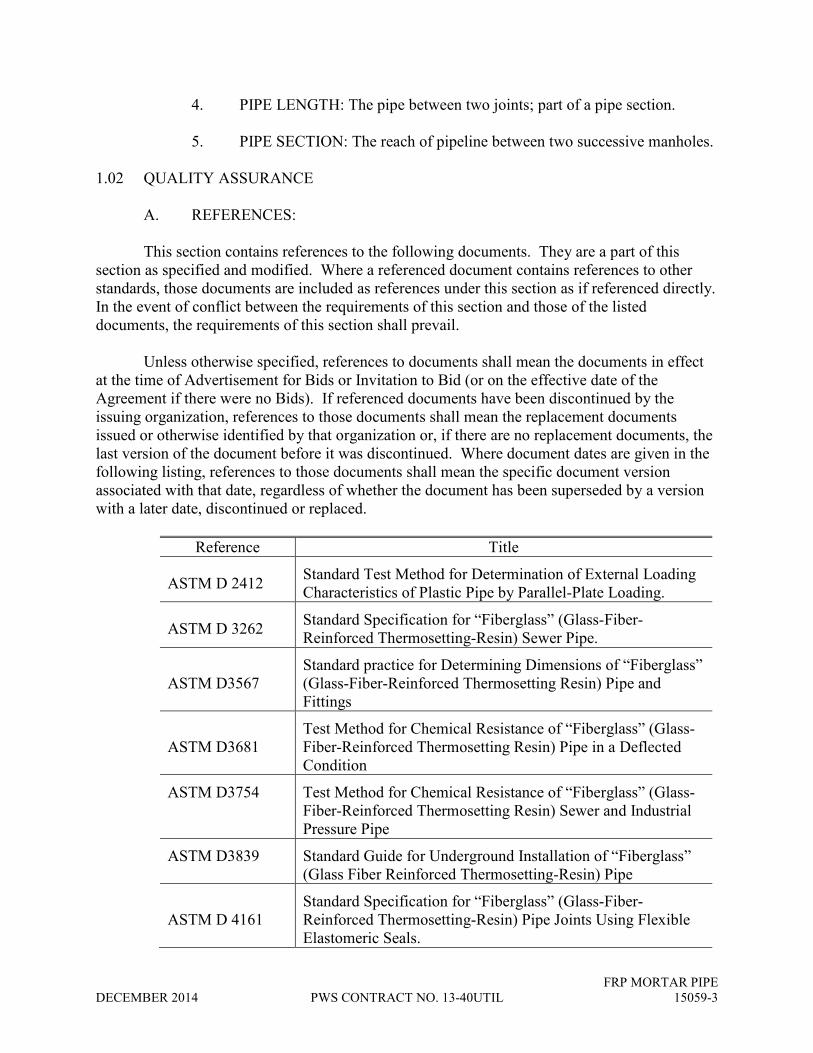
FRP MORTAR PIPE
DECEMBER 2014 PWS CONTRACT NO. 13-40UTIL 15059-3
4. PIPE LENGTH: The pipe between two joints; part of a pipe section.
5. PIPE SECTION: The reach of pipeline between two successive manholes.
1.02 QUALITY ASSURANCE
A. REFERENCES:
This section contains references to the following documents. They are a part of this
section as specified and modified. Where a referenced document contains references to other
standards, those documents are included as references under this section as if referenced directly.
In the event of conflict between the requirements of this section and those of the listed
documents, the requirements of this section shall prevail.
Unless otherwise specified, references to documents shall mean the documents in effect
at the time of Advertisement for Bids or Invitation to Bid (or on the effective date of the
Agreement if there were no Bids). If referenced documents have been discontinued by the
issuing organization, references to those documents shall mean the replacement documents
issued or otherwise identified by that organization or, if there are no replacement documents, the
last version of the document before it was discontinued. Where document dates are given in the
following listing, references to those documents shall mean the specific document version
associated with that date, regardless of whether the document has been superseded by a version
with a later date, discontinued or replaced.
Reference Title
ASTM D 2412 Standard Test Method for Determination of External Loading
Characteristics of Plastic Pipe by Parallel-Plate Loading.
ASTM D 3262 Standard Specification for “Fiberglass” (Glass-Fiber-
Reinforced Thermosetting-Resin) Sewer Pipe.
ASTM D3567
Standard practice for Determining Dimensions of “Fiberglass”
(Glass-Fiber-Reinforced Thermosetting Resin) Pipe and
Fittings
ASTM D3681
Test Method for Chemical Resistance of “Fiberglass” (Glass-
Fiber-Reinforced Thermosetting Resin) Pipe in a Deflected
Condition
ASTM D3754 Test Method for Chemical Resistance of “Fiberglass” (Glass-
Fiber-Reinforced Thermosetting Resin) Sewer and Industrial
Pressure Pipe
ASTM D3839 Standard Guide for Underground Installation of “Fiberglass”
(Glass Fiber Reinforced Thermosetting-Resin) Pipe
ASTM D 4161
Standard Specification for “Fiberglass” (Glass-Fiber-
Reinforced Thermosetting-Resin) Pipe Joints Using Flexible
Elastomeric Seals.

FRP MORTAR PIPE
15059-4 PWS CONTRACT NO. 13-40UTIL DECEMBER 2014
Reference Title
ASTM F 447 Standard Specifications for Elastomeric Seals (Gaskets) for
Joining Plastic Pipe.
ISO 9001 Total Quality Control Management System
SSPWC Standard Specification for Public Works Construction
“Greenbook”.
A. MANUFACTURER REQUIREMENTS
Manufacturer shall maintain a continuous Quality Control Program and shall provide the
Construction Manager with certified test reports.
Manufacturer shall provide ISO 9001 certificate by a third party confirming that all
ASTM Test reports are valid and up to date at the time of bid and fabrication of the furnished
product.
The manufacturer of pipe and fittings must demonstrate 10 consecutive years of
experience in producing similar type products of successful history of production for sewer
service in the United States with a minimum of 500,000 linear feet of pipe installed in similar or
larger diameters and provide upon request, references for a minimum 10 open-cut, 10 carrier
tunnel and 10 microtunnel projects with 48-inch and larger pipe sizes, demonstrating the
successful installation, grouting and joint integrity of the pipe design.
Pipe and fittings shall be the product of one manufacturer. All pipe shall be manufactured
specifically for this project. No pipe shall be furnished from stock unless approved by the
Construction Manager.
B. QUALIFICATION TESTING
Contractor shall submit a manufacturer’s affidavit that all provided materials have been
tested and meet or exceed the performance requirements of ASTM D2412, ASTM D3262,
ASTM D4161 and ASTM D3681 when tested using 1N sulfuric acid and SSPWC Section 207-
20.5.
The Contractor, at their expense, shall furnish certified test data as required by the Owner
to demonstrate compliance with specified performance requirements including but not limited to
quality control, quality assurance, strength, chemical and abrasion resistance, dimensional
tolerance, and suitability such that furnished pipe fulfill its specified function. Tests and testing
methods shall be subject to review and acceptance by the Owner.
The Owner or their designated representative shall be entitled to inspect pipes or witness
pipe fabrication and material testing at the manufacturer’s facilities at no additional cost to the
Owner. Such inspection shall in no way relieve the manufacturer of the responsibilities to
provide products that comply with the applicable standards and these Specifications. The
Contractor shall provide the Owner’s Representative with four (4) weeks’ notice of the start of
fabrication of pipe to be furnished.

FRP MORTAR PIPE
DECEMBER 2014 PWS CONTRACT NO. 13-40UTIL 15059-5
The Contractor shall include in their Bid, the cost for two (2) Owner or their designated
representatives to visit and inspect the pipe manufacturer’s facilities.
1.03 SUBMITTALS
The Contractor shall submit the following in compliance with the General Conditions and
Section 01300.
A. SHOP DRAWINGS: Submit the following:
1. Detailed drawings of the pipe, gaskets, joints, expansion joints, pipe
special sections and connections. Detailed drawings shall provide
dimensions of pipes including inside diameter and wall thicknesses and
details of pipe joints and gaskets with test reports on the properties of the
gasket material.
2. Pipe-laying diagrams showing the location, length, strength designation,
and number or marking designation of each pipe section, manhole, and
fitting to be furnished. The station and elevation of the pipe invert at all
changes in grade and all data on curves and bends for both horizontal and
vertical alignment shall also be shown. Include the following information:
a. Quantities and laying lengths of each piece.
b. Invert stations with respect to the Project baseline.
c. Invert grade with respect to horizontal between each change of
grade.
d. Invert elevations referenced to Project vertical datum at each
change in horizontal geometry and vertical grade.
e. Maximum allowable joint deflections for each type of joint to
nearest 1/8 inch; top or bottom, left or right.
B. MARKING SCHEDULE: Marks to be used on the finished products to identify
pipes, specials and accessories shown on shop drawings and laying schedules.
Coordinate identification of each piece with shop drawings, product data, and
marking schedule. Design Calculations for wall thickness, pipe class and stiffness
and product data as necessary to fully describe all materials, components, and
finished products and to show conformance with the Contract Documents.
C. Pipe joint test procedures describing method of joint testing.
D. Manufacturer’s certificate of compliance with the requirements per Paragraph
1.02.B of this Section.

FRP MORTAR PIPE
15059-6 PWS CONTRACT NO. 13-40UTIL DECEMBER 2014
E. Manufacturers Certificate of Compliance stating pipe and fittings provided are in
accordance with the requirements of this Section and referenced Standards for
each size of pipe and fittings used. Provide certified test results upon request.
F. Provide an affidavit of compliance for the provided gasket that it is suitable for
use in sanitary sewer systems, manufactured in accordance with ASTM D4161
and meets the minimum requirements of ASTM F477. Provide certified test
results upon request per Section 15075.
G. Manufacturer instructions on storage, handling, transportation, and installation.
H. Design calculations and manufacturer’s statement verifying calculations.
I. Color samples for bridge and exposed pipe demonstrating compliance with
paragraph 1.01-B.1.g.
1.04 DESIGN REQUIREMENTS
The Contractor shall design and prepare lay drawings of the pipe to meet the service
conditions of the installation such as imposed jacking forces/microtunneling, and criteria as
specified.
A. DESIGN CRITERIA:
Minimum criteria for design of piping systems shall include the following:
1. Service Conditions:
a. Liquid Service: Sewage.
b. Flow Conditions: Low Head Pressure Flow.
2. External loads imposed on pipelines include earth load, live load, and
forces imposed on the pipe by the Contractor’s means and methods.
Minimum values shall be as follows:
a. Depth of cover shall be as shown.
b. Minimum earth load for design of pipe shall be a unit weight of
soil of 130 pounds per cubic foot.
c. Native soil conditions as provided by Geotechnical Investigations.
d. Under Roadways: AASHTO H20 truck loading with earth cover.

FRP MORTAR PIPE
DECEMBER 2014 PWS CONTRACT NO. 13-40UTIL 15059-7
e. Under Railroads and within Railroad Right-of-Way: Cooper E80
live loading with earth cover.
f. Hydrostatic loading shall assume groundwater to existing grade.
3. Long term creep properties of resin system
4. Pipe expansion, including thermal, and as resulting from pipe / bridge
connection.
5. Installation methods shall be as shown on the Drawings. The design shall
take into account, jacking forces, estimated pipe string compression,
eccentric forces due to steering (0.5 degree joint deflection), and any other
installation forces or loads which may be reasonably anticipated
6. Axial and circumferential strength dependent upon the configuration of
fiberglass reinforcement shall be accounted for in determining pipe
capacity to withstand loading conditions. Strength derived from
circumferential filament winding shall not be included in compressive
strength calculations.
7. Interior surface liner shall not be used in structural calculations.
1.05 MATERIALS TRANSPORTATION, HANDLING AND STORAGE
Handle all pipe, fittings, and appurtenances carefully with proper handling devices: web
slings, padded slings and clean, padded forks in accordance with manufacturer’s
recommendations.
Store pipe, fittings and appurtenances on heavy wood blocking or platforms so they are
not in contact with the ground.
Materials cracked, gouged, chipped, dented or otherwise damaged will not be accepted.
Minor defects in the pipe or coatings may be repaired at the site by a method approved by the
manufacturer and the Engineer. Damaged pipe, fittings and appurtenances shall be repaired or
replaced at Contractor’s expense.
1.06 PIPE SCHEDULE
A. SCHEDULE A:
SHEETSHEETSHEETSHEET FROM FROM FROM FROM
STATIONSTATIONSTATIONSTATION TO TO TO TO
STATIONSTATIONSTATIONSTATION PIPE DIA PIPE DIA PIPE DIA PIPE DIA
(IN)(IN)(IN)(IN) HORIZ HORIZ HORIZ HORIZ
LENGTH (FT)LENGTH (FT)LENGTH (FT)LENGTH (FT) PIPE PIPE PIPE PIPE
MATERIALMATERIALMATERIALMATERIAL INSTALLATIONINSTALLATIONINSTALLATIONINSTALLATION
C2 1+03.00 1+10.00 54 7.00 CCFRPM or
FRP Open Cut/Embankment
C2 1+10.00 4+09.13 54 299.13 CCFRPM or
FRP Open Cut/Embankment
C2 4+09.13 6+15.99 54 206.86 CCFRPM or
FRP Open Cut/Embankment
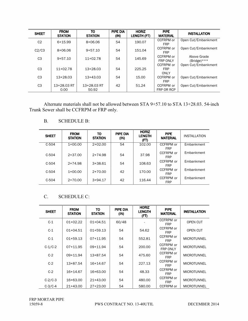
FRP MORTAR PIPE
15059-8 PWS CONTRACT NO. 13-40UTIL DECEMBER 2014
SHEETSHEETSHEETSHEET FROM FROM FROM FROM
STATIONSTATIONSTATIONSTATION TO TO TO TO
STATIONSTATIONSTATIONSTATION PIPE DIA PIPE DIA PIPE DIA PIPE DIA
(IN)(IN)(IN)(IN) HORIZ HORIZ HORIZ HORIZ
LENGTH (FT)LENGTH (FT)LENGTH (FT)LENGTH (FT) PIPE PIPE PIPE PIPE
MATERIALMATERIALMATERIALMATERIAL INSTALLATIONINSTALLATIONINSTALLATIONINSTALLATION
C2 6+15.99 8+06.06 54 190.07 CCFRPM or
FRP Open Cut/Embankment
C2/C3 8+06.06 9+57.10 54 151.04 CCFRPM or
FRP Open Cut/Embankment
C3 9+57.10 11+02.78 54 145.69 CCFRPM or FRP ONLY
Above Grade (Bridge)***
C3 11+02.78 13+28.03 54 225.25 CCFRPM or
FRP ONLY
Open Cut/Embankment
C3 13+28.03 13+43.03 54 15.00 CCFRPM or FRP
Open Cut/Embankment
C3 13+28.03 RT 0.00
13+28.03 RT 50.92
42 51.24 CCFRPM or FRP OR RCP
Open Cut/Embankment
Alternate materials shall not be allowed between STA 9+57.10 to STA 13+28.03. 54-inch
Trunk Sewer shall be CCFRPM or FRP only.
B. SCHEDULE B:
SHEETSHEETSHEETSHEET FROM FROM FROM FROM
STATIONSTATIONSTATIONSTATION TO TO TO TO
STATIONSTATIONSTATIONSTATION PIPE DIA PIPE DIA PIPE DIA PIPE DIA
(IN)(IN)(IN)(IN)
HORIZ HORIZ HORIZ HORIZ LENGTH LENGTH LENGTH LENGTH
(FT)(FT)(FT)(FT)
PIPE PIPE PIPE PIPE MATERIALMATERIALMATERIALMATERIAL
INSTALLATION
C-504 1+00.00 2+02.00 54 102.00 CCFRPM or FRP
Embankment
C-504 2+37.00 2+74.98 54 37.98 CCFRPM or
FRP
Embankment
C-504 2+74.98 3+38.61 54 108.63 CCFRPM or
FRP Embankment
C-504 1+00.00 2+70.00 42 170.00 CCFRPM or
FRP Embankment
C-504 2+70.00 3+94.17 42 116.44 CCFRPM or
FRP Embankment
C. SCHEDULE C:
SHEETSHEETSHEETSHEET FROM FROM FROM FROM
STATIONSTATIONSTATIONSTATION TO TO TO TO
STATIONSTATIONSTATIONSTATION PIPE DIA PIPE DIA PIPE DIA PIPE DIA
(IN)(IN)(IN)(IN)
HORIZ HORIZ HORIZ HORIZ LENGTH LENGTH LENGTH LENGTH
(FT)(FT)(FT)(FT)
PIPE PIPE PIPE PIPE MATERIALMATERIALMATERIALMATERIAL
INSTALLATIONINSTALLATIONINSTALLATIONINSTALLATION
C-1 01+02.22 01+04.51 60/48 - CCFRPM or
FRP OPEN CUT
C-1 01+04.51 01+59.13 54 54.62 CCFRPM or
FRP OPEN CUT
C-1 01+59.13 07+11.95 54 552.81 CCFRPM or
FRP MICROTUNNEL
C-1/C-2 07+11.95 09+11.94 54 200.00 CCFRPM or FRP ONLY
MICROTUNNEL
C-2 09+11.94 13+87.54 54 475.60 CCFRPM or
FRP MICROTUNNEL
C-2 13+87.54 16+14.67 54 227.13 CCFRPM or
FRP MICROTUNNEL
C-2 16+14.67 16+63.00 54 48.33 CCFRPM or
FRP MICROTUNNEL
C-2/C-3 16+63.00 21+43.00 54 480.00 CCFRPM or
FRP MICROTUNNEL
C-3/C-4 21+43.00 27+23.00 54 580.00 CCFRPM or MICROTUNNEL

FRP MORTAR PIPE
DECEMBER 2014 PWS CONTRACT NO. 13-40UTIL 15059-9
SHEETSHEETSHEETSHEET FROM FROM FROM FROM
STATIONSTATIONSTATIONSTATION TO TO TO TO
STATIONSTATIONSTATIONSTATION PIPE DIA PIPE DIA PIPE DIA PIPE DIA
(IN)(IN)(IN)(IN)
HORIZ HORIZ HORIZ HORIZ LENGTH LENGTH LENGTH LENGTH
(FT)(FT)(FT)(FT)
PIPE PIPE PIPE PIPE MATERIALMATERIALMATERIALMATERIAL
INSTALLATIONINSTALLATIONINSTALLATIONINSTALLATION
FRP C-4 27+23.00 33+13.00 54 590.00 CCFRPM or
FRP MICROTUNNEL
C-4/C-5 33+13.00 38+33.00 54 520.00 CCFRPM or FRP
MICROTUNNEL
C-5/C6 38+33.00 45+80.00 54 747.00 CCFRPM or FRP
OPEN CUT OR MICROTUNNEL
C-6 45+80.00 53+08.43 54 728.43 CCFRPM or FRP
OPEN CUT OR MICROTUNNEL
C-6/C-7 53+08.43 57+28.32 54 419.89 CCFRPM or FRP
OPEN CUT
C-7 57+28.32 61+82.87 54 454.55 CCFRPM or FRP
OPEN CUT
C-7/C-8 61+82.87 68+97.00 54 714.13 CCFRPM or FRP
OPEN CUT
D. SCHEDULE D: (NOT USED)
PART 2 – PRODUCTS
2.01 MATERIALS
A. RESIN SYSTEMS:
The manufacturer shall use US made polyester resin systems with a proven history of
performance in sanitary sewer applications. The historical data shall have been acquired from a
composite material of similar construction and composition as the proposed product.
Polyester wall resin shall be an isophthalic, orthophththalic or other approved resin with a
minimum tensile elongation of 2 percent. A vinyl ester liner shall be provided to meet chemical
resistance requirements.
B. GLASS REINFORCEMENTS:
The reinforcing glass fibers used to manufacture the components shall be commercial
grade E-type glass fibers with a size and finish compatible with the resin provided.
C. AGGREGATE:
Silica sand shall be minimum 98% silica with a maximum moisture content of 0.2% per
ASTM D3262. Sand shall conform to ASTM C33, excluding gradation requirements.
D. ADDITIVES:
Resin additives, such as curing agents, pigments, dyes, fillers, thixotropic agents, etc.,
when used, shall not detrimentally effect the performance of the product.

FRP MORTAR PIPE
15059-10 PWS CONTRACT NO. 13-40UTIL DECEMBER 2014
E. ELASTOMERIC GASKETS:
Gaskets shall be EPDM elastomeric sealing gaskets in accordance with ASTM F477
supplied by approved gasket manufacturers. Gaskets shall meet the performance requirements
ASTM D4161 and the chemical composition of the gasket shall be compatible with the type of
environment to which it will be subjected.
2.02 MANUFACTURE
A. PIPE:
Pipe shall be centrifugally cast fiberglass-reinforced mortar pipe (CCFRPM) per ASTM
D3262, Cell Class Type 1, Liner 2, Grade 3 or filament wound (FRP) per ASTM D3262 Cell
Class Type 1, Liner 1, Grade 1. Pipe Stiffness Class shall be D or higher as required for
installation and service conditions. Pipe for trenchless construction shall also conform with
manufacturing and testing requirements of ASTM D2412.
The resins, reinforcements, colorants, and other materials, when combined as a composite
structure shall produce a pipe that meets the performance requirements for ASTM D3262 and a
dense, non-porous, corrosion-resistant, consistent composite structure.
1. Diameters:
a. The actual outside diameter of the pipes shall be in accordance
with ASTM D3262.
2. Lengths:
a. Pipe shall be supplied in nominal lengths. At least 90% of the total
footage of each size and class of pipe, excluding special order
length sections. Nominal lengths shall be as follows:
a. Direct Bury: 20 feet except as otherwise specified or
required for bends or special joints, with the minimum
length of 5 feet .
b. Microtunnel: 6, 10, or 20 feet. Actual laying length shall be
nominal +/- ½ inch.
c. Above Ground (Bridge): 10 feet except as otherwise or
required for expansion joints, with the minimum length of 5
feet.
3. Wall thickness and Weight: Minimum pipe stiffness and the wall
thickness of pipes when tested in accordance with ASTM D2412 shall be
per the following table:

FRP MORTAR PIPE
DECEMBER 2014 PWS CONTRACT NO. 13-40UTIL 15059-11
Nominal Dia &
Installation
Pressure (psi)
Minimum
Wall Thickness
(in)
Pipe OD
(in)
54” Direct Buried Class D - SN 72 psi 1.21 57.1 ±
0.010”
60” Direct Buried Class D - SN 72 psi 1.33 62.9 ±
0.010”
54” Microtunneling Pipe SN 140 psi 2.10 57.1 ±
0.010”
54” Above Ground
(Bridge) Class D - SN 72 psi 1.21
57.1 ±
0.010”
The minimum pipe stiffness and wall thickness of pipes shall be increased as
required to reflect loads and stresses on the pipe due to jacking installation
requirements. The minimum wall thickness, measured at the bottom of the spigot
gasket groove where the wall cross-section has been reduced, is determined from
the maximum jacking load.
4. Tolerances: Microtunnel pipe shall meet minimum tolerances for
straightness, roundness and end squareness in accordance with SSPWC
Section 207-22.3.3.
5. A minimum compressive strength of 10,000 psi per ASTM C579.
6. The interior surface shall provide chemical, crack and abrasion resistance
and shall be a minimum 20 mil resin rich layer.
7. The exterior surface shall be a minimum 20 mil thick silica sand resin
mixture over all reinforcement. The surface layer shall contain sufficient
UV inhibitor to protect the underlying resin from UV degradation.
8. Where reinforcement is provided within the interior or exterior surface, a
resin rich non-reinforced layer a minimum of 5 mils thick shall be
provided.
B. JOINTS:
Unless otherwise indicated, joints shall be axially unrestrained bell-and-spigot/flush bell
and spigot gasket joints including couplings using flexible elastomeric seals to obtain soundness
and shall conform to ASTM D4161. The pipe joint shall also be rated to 100 psi external
pressure for zero infiltration service. Third party test report, confirming the external pressure
rating, shall be submitted to the owner.
The joint may be bell-and-spigot or coupling joint with the gasket placed in the bell in
circumferential compression or the gasket may be placed on the spigot in circumferential tension.
When the joint is assembled, the gasket shall be compressed to substantially fill the groove and

FRP MORTAR PIPE
15059-12 PWS CONTRACT NO. 13-40UTIL DECEMBER 2014
affect a watertight seal. FRP sliplining and Jacking joints/couplings shall be flush with the pipe
barrel within -0.0” and +0.150” tolerances.
Type Joint
54” Direct Buried Bell and Spigot or FWC Coupling or equal
60” Direct Buried Bell and Spigot or FWC Coupling or equal
54” Microtunneling Pipe Flush Bell and Spigot Jacking joints/couplings
54” Above Grade (Bridge) FWC Coupling or equal
Joint assemblies shall be so formed and accurately manufactured that when the pipes are
drawn together; the pipe shall form a continuous watertight conduit with smooth and uniform
interior surface, and shall provide for slight movements of any pipe in the pipeline due to
expansion, contraction, settlement, or lateral displacement. Shape and dimensions of the joint
shall be such that it will be self-centering upon closure, and so designed that the gasket will not
be required to support the weight of the pipe. Rubber gasket shall be the sole element of the joint
depended upon to provide water-tightness. Ends of the pipe shall be in planes at right angles to
the longitudinal centerline of the pipe. Ends of the pipe units shall be finished to regular smooth
surfaces.
Gasket material shall be EPDM and meet the performance requirements of ASTM D4161
and the chemical composition of the gasket shall be compatible for sanitary sewer service. The
direct buried pipe couplings shall utilizes a fiberglass composite outer ring with full face double
fin inner gasket, which is mechanically locked into the coupling to ensure rapid and error free
zero leak installation, FWC by HOBAS or equal
Gaskets shall be formulated by:
1. Polymer & Rubber (USA),
2. Or approved equal
C. FITTINGS:
Fittings shall be manufactured from mitered sections of fiberglass pipe.
D. PIPE MARKINGS:
Pipe markings shall be in accordance with SSPWC Sections 207-20.6 unless specified
otherwise. Plainly mark the exterior of each length of straight pipe and each fitting to identify
the pipe diameter, the design pressure class, the pipe stiffness, ASTM designation, the date of
manufacture, and the name and location of the pipe manufacturer. The maximum allowable
JACKING LOAD SHALL ALSO BE INDICATED FOR MICROTUNNEL PIPE.
E. ACCEPTABLE MANUFACTURERS:

FRP MORTAR PIPE
DECEMBER 2014 PWS CONTRACT NO. 13-40UTIL 15059-13
Provide one of the following:
1. CCFRPM - Hobas Pipe USA, Inc.
2. FRP - Thompson Pipe Group, Flowtite,
3. Or approved equal
2.03 CHEMICAL TESTING AND PHYSICAL TESTING
A. CHEMICAL TESTING:
Chemical resistance of the inner liner shall be demonstrated with a minimal loss of tensile
or impact strength after four months continuous immersion for the following solutions: 20%
sulfuric acid, 1% ferric chloride, 1% nitric acid, 0.1% soap, 0.1% commercial detergent as linear
alkyl benzyl sulfonate, and 700 ppm biological oxygen demand (BOD) or acidity range of
1<pH<9. When tested per ASTM D3681 using 1 pH sulfuric acid, the pipe shall demonstrate a
minimum strain level of 0.9% for 100 year service life at 5% deflection. .
B. PHYSICAL TESTING:
Pipes shall be manufactured and tested in accordance with ASTM D3262. The
manufacturing process shall result in a dense, non-porous, corrosion-resistant, consistent
composite structure.
2.04 APPURTENANCES
A. FITTINGS:
Flanges, elbows, reducers, tees, wyes, laterals and other fittings shall be capable of
withstanding all operating conditions when installed.
2.05 TRUNK SEWER MANHOLES
Fiberglass tee base and one piece fiberglass riser manholes equal to the provided
fiberglass cylinder pipe shall be provided as specified. .
The tee base connections to the trunk sewer pipe and riser section shall be push-on,
gasket-sealed FWC couplings or equal as recommended by the manufacturer for the installation
and service conditions.
Fully concrete encase the tee base as specified. The concrete encasement shall be
designed to support riser loads and traffic loading and extend past the first coupling/joint.
2.06 PIPE CONNECTIONS TO CAST-IN-PLACE AND PRECAST STRUCTURES
Connections shall be Kor-n-Seal, Press-Seal, or approved equal:
1. Watertight, flexible expandable boot per ASTM C-923,

FRP MORTAR PIPE
15059-14 PWS CONTRACT NO. 13-40UTIL DECEMBER 2014
2. Watertight non-metalic, nonshrink Type V grout and hydrophilic Nitrile
waterstop gasket in accordance with ASTM C-923
B. Hardware shall be 300 series stainless steel. Gaskets shall be natural or synthetic
rubber. No plastic components shall be permitted.
C. Pipe manufacturer’s wall fitting at the Bridge wall abutment (Schedule A) and
Lift Station and the Grinding Facility (Schedule B) shall be cast into wall. Wall
fittings shall be FWC coupling wall fitting per HOBAS or approved equal.
PART 3 – EXECUTION
3.01 GENERAL
A. INSPECTION:
Inspect each pipe prior to installation. The pipe shall be free of cracks, crazing, holes,
delamination, foreign inclusions, air bubbles, blisters, or other deleterious defects. Field repair of
pipe or linings damaged by unloading or installation procedures will be permitted, subject to
review of the proposed repair procedures by the OWNER. Alternatively, replace the defective
pipe or fitting or field cut to remove the damaged portion of pipe. Pipe intended for tunneling
shall not be field cut, except to connect to direct-burial pipe.
B. INSTALLATION:
The installation of pipe and fittings shall be in accordance with ASTM D3839, Section
02223, the manufacturer's recommendations, and as specified.
1. When installing piping in trenches, do not deviate more than 1 inch from
line or ¼ inch from grade. Measure for grade at the pipe invert.
2. Do not deflect rubber gasket joints more than the manufacturer's
recommended maximum joint deflection angle.
3. Carefully clean pipe end and gasket prior to insertion into the coupling.
Apply soap solution approved by the pipe manufacturer immediately prior
to joining the pipes. Check completed joint with feeler gauge to make sure
the gasket is completely seated around the circumference of the pipe.
4. Protect pipe integrity for all installation methods and phases of
construction. This includes, but is not limited to safe handling, utilization
of Manufacturer approved installation procedures, and proper protection
and installation methods during trenchless installation, as required by
specification section 02345, including but not limited to, use of packer
rings at the joints to distribute jacking loads.

FRP MORTAR PIPE
DECEMBER 2014 PWS CONTRACT NO. 13-40UTIL 15059-15
C. PIPE HANDLING:
Use textile slings, other suitable materials or a forklift. Use of chains or cables shall not
be permitted.
D. JOINING:
Clean ends of pipe and joint components.
Apply joint lubricant to the bell interior surface and the elastomeric seals. Use only
lubricants approved by the pipe manufacturer.
Use suitable equipment and end protection to push the pipes together.
Do not exceed forces recommended by the manufacturer for jointing or pushing pipe.
3.02 PIPELINE ACCEPTANCE AND TESTS
A. DEFLECTION TESTING:
Pipe deflection shall be tested after backfill is complete. Pipe initial vertical cross-section
deflection shall not exceed 3% of the original pipe diameter. Provide inspection data to
Construction Manager.
B. AIR PRESSURE TEST:
The air test shall comply with SSPWC Subsection 306-1.4.4. Joints may be air tested
individually with the use of specialized equipment provided the joint testing procedure is
submitted for the Construction Manager’s review prior to testing (see 3.2C). Prior to each test,
the pipe at the joint shall be wetted with water. The maximum test pressure shall be 3.0 psi. The
maximum allowable pressure drop shall be 1.0 psi over a 30-second test period. Not more than
one (1 ) joint shall be air tested at any one time.
C. JOINT PRESSURE TESTING:
Pressure test each pipe joint using portable pipe joint tester prior to backfilling or
grouting. Repair joint leaks which do not meet the leakage criteria.
Pipe Joint tester shall meet the following criteria:
1. Pressure cylinder which fits inside pipe, straddles pipe joint and isolates
and pressurizes a section of pipe.
2. Elastomeric sealing elements encircle the joint tester body so that when
inflated or deformed they affect a seal between the joint tester body and
the interior surface of the pipe. Sealing elements shall be designed to
resist test pressure at an inflation pressure that does not exceed capacity of
pipe.

FRP MORTAR PIPE
15059-16 PWS CONTRACT NO. 13-40UTIL DECEMBER 2014
3. Data plate: References pipe diameter, rated test pressure, inflation pressure
and any torque requirements for threaded fasteners.
Acceptable manufacturer:
1. Mechanical Research & Design, Inc.
2. Lansas Products.
3. Approved equal.
** END OF SECTION **

STEEL PIPE
DECEMBER 2014 PWS CONTRACT NO. 13-40UTIL 15061-1
SECTION 15061
STEEL PIPE
PART 1 -- GENERAL
1.01 DESCRIPTION
A: SCOPE
Furnish and install steel pipe, fittings, specials and closure pieces as specified and shown
on Drawings.
B. DEFINITIONS
SPECIALS: A special is defined as any piece of pipe other than a normal full length of
straight pipe. This includes, but is not limited to, elbows, short pieces, reducers, tees, crosses,
spools, sections with outlets, beveled sections and access holes.
1.02 QUALITY ASSURANCE
A. REFERENCES:
This section contains references to the following documents. They are a part of this
section as specified and modified. Where a referenced document contains references to other
standards, those documents are included as references under this section as if referenced directly.
In the event of conflict between the requirements of this section and those of the listed
documents, the requirements of this section shall prevail.
Unless otherwise specified, references to documents shall mean the documents in effect
at the time of Advertisement for Bids or Invitation to Bid (or on the effective date of the
Agreement if there were no Bids). If referenced documents have been discontinued by the
issuing organization, references to those documents shall mean the replacement documents
issued or otherwise identified by that organization or, if there are no replacement documents, the
last version of the document before it was discontinued. Where document dates are given in the
following listing, references to those documents shall mean the specific document version
associated with that date, regardless of whether the document has been superseded by a version
with a later date, discontinued or replaced.

STEEL PIPE
15061-2 PWS CONTRACT NO. 13-40UTIL DECEMBER 2014
Reference Title
ANSI B16.3 Malleable Iron Threaded Fittings, Class 150 and 300
ANSI B16.9 Factory-Made Wrought Steel Buttwelding Fittings
ANSI B16.11 Forged Steel Fittings, Socket-Welding and Threaded
ASTM A36/A36M Structural Steel
ASTM A47 Ferritic Malleable Iron Castings
ASTM A53 Pipe, Steel, Black and Hot-Dipped, Zinc-Coated Welded
and Seamless
ASTM A105/A105M Forgings, Carbon Steel, for Piping Components
ASTM A106 REV A Seamless Carbon Steel Pipe for High-Temperature Service
ASTM A197 Cupola Malleable Iron
ASTM A234/A234M Pipe Fittings of Wrought Carbon Steel and Alloy Steel for
Moderate and Elevated Temperatures
ASTM A283/A283M
REV A
Low and Intermediate Tensile Strength Carbon Steel
Plates, Shapes and Bars
ASTM A536 Ductile Iron Castings
ASTM A570/A570M Hot-Rolled Carbon Steel Sheet and Strip, Structural
Quality
ASTM A572/A572M
REV B
High Strength Low Alloy Columbium-Vanadium Steels of
Structural Quality
AWWA C200 Steel Water Pipe 6 Inches and Larger
AWWA C205 Cement-Mortar Protective Lining and Coating for Steel
Water Pipe--4 In. and Larger-- Shop Applied
AWWA C206 Field Welding of Steel Water Pipe
AWWA C207 Steel Pipe Flanges for Waterworks Services--Sizes 4 In.
Through 144 In.
AWWA C208 Dimensions for Fabricated Steel Water Pipe Fittings
AWWA C209 Cold-Applied Tape Coating for Special Sections,
Connections, and Fittings for Steel Water Pipelines
AWWA C210 Liquid Epoxy Coating Systems for the Interior and
Exterior of Steel Water Pipe
AWWA C213 Fusion Bonded Epoxy Coating for the Interior and Exterior
of Steel Water Pipelines
AWWA C214 Tape Coating Systems for the Exterior of Steel Water
Pipelines

STEEL PIPE
DECEMBER 2014 PWS CONTRACT NO. 13-40UTIL 15061-3
Reference Title
AWWA C600 Installation of Ductile-Iron Water Mains and Their
Appurtenances
AWWA M11 Steel Pipe--A Guide for Design and Installation
ASME Boiler and Pressure Vessel Code
SSPC-SP10 Near-White Blast Cleaning
B. TESTING:
Factory testing shall conform to the requirements of ASTM A53, ASTM A106, or
AWWA C200 as applicable.
In addition to the shop hydrostatic testing performed on pipe cylinders required per
AWWA C200, all welds of specials and attachments (for example, joint rings, nozzles, and
supports) shall be tested by a dye-penetrant process. Certification of such testing shall be
submitted to the Construction Manager.
Field welders shall be certified under Section IX, Part A of the ASME Boiler and
Pressure Vessel Code or in accordance with AWWA C206, Section 3. Welders shall present a
copy of their certification to the Construction Manager prior to performing any field welding.
Certifications shall be dated within three (3) years of the job to be performed.
PART 2 -- PRODUCTS
2.01 PIPE MATERIALS
Steel pipe and fittings shall be provided in accordance with ASTM A53, ASTM A106, or
AWWA C200 as specified in Section 15050, Piping Systems.
Steel for pipe fabricated to meet requirements of AWWA C200 shall conform to the
requirements of ASTM A36, ASTM A572, Grade 42, ASTM A570, Grades 33 and 36, or ASTM
A283, Grade D. Steel for ASTM A53 and ASTM A106 pipe shall be Grade B.
2.02 PIPE MANUFACTURE
Unless otherwise specified, ASTM A53 pipe shall be Type E, electric resistance welded
or Type S, seamless pipe as specified in Section 15050. The minimum wall thickness for ASTM
A53 or ASTM A106 pipe shall be Schedule 40 for pipe 10 inch diameter and less and 3/8 inch
for pipe 12 inch through 24 inch diameter. Increased shell thickness shall be provided where
specified.

STEEL PIPE
15061-4 PWS CONTRACT NO. 13-40UTIL DECEMBER 2014
AWWA C200 pipe shall be straight or spiral seam. The minimum wall thickness shall be
7 gage for pipe 6 inch through 8”, 3/8” for pipe 10” through 24 inch diameter and 1/4 inch for
pipe 26 inch diameter and larger. Increased shell thickness shall be provided where specified or
required for operating conditions or installation methods.
Specials shall be fabricated from materials or straight pipe in full conformance with the
requirements of AWWA C200, and the dimensions of ANSI/AWWA C208. All fittings and
specials shall be properly reinforced to withstand the internal pressure, with circumferential and
longitudinal, or external loading conditions, whichever is greater. The minimum thickness of
plate for pipe from which specials are to be fabricated shall be the thickness of adjacent mainline
pipe or as specified, whichever is greater.
A. STEEL PIPE SCHEDULES:
Design Responsibility: The design and layout of pipe shall meet the service conditions
and the criteria specified in this Section and as shown on the Plans are the responsibility of the
Contractor. This design shall be performed by or under the supervision of a Professional
Engineer licensed by the State of California. Pipe and specials shall have the following minimum
wall thicknesses in accordance with AWWA Manual M-11 based on ASTM A106, grade B steel
pipe. The Contractor shall submit design calculations for steel pipe and specials with steel
properties and wall thickness demonstrating that the pipe is capable of sustaining the maximum
stresses to be imposed during installation and service.
1. SCHEDULE B: Thickness and test pressures are identified on the
drawings and in specification Section 15050.
2. SCHEDULE C: Unless otherwise specified, 10 inch nominal diameter
cylinder pipe and fittings (specials) for potable water transmission mains shall be cement mortar
lined and tape wrapped and cement coated steel pipe in accordance with AWWA C200, AWWA
C205 and CWMD standards.
3. SCHEDULE D: Unless otherwise specified, 18 inch nominal diameter
cylinder pipe and fittings (specials) for recycled water transmission mains shall be cement mortar
lined and tape wrapped and cement mortar coated. Tape wrap shall be in accordance with Section
09870 The piping system shall conform with the following:
a. Working Pressure 175 psig
b. Surge Pressure 235 psig
c. Maximum deflection in installed
condition, percent of the average
inside diameter of the pipe 3.0

STEEL PIPE
DECEMBER 2014 PWS CONTRACT NO. 13-40UTIL 15061-5
Fabricated
Pipe
Nominal Pipe
Size
(inches)
Steel
Cylinder
O.D.
(inches)
Steel
Cylinder
Wall
Thickness
(inches)
Steel Cylinder 12 12.750 0.1345
Steel Cylinder 18 19.781 0.1345
Steel Specials 18 19.781 0.1850
2.03 CONNECTIONS
Connections shall be as specified in Section 15050 and shall conform to Section 15085.
Coating for buried connections shall be as specified in paragraph 15085-2.06.
Flanged coupling adapters shall be installed in accordance with the manufacturer's
recommendations. Bolts shall be tightened with a torque wrench in the presence of the
Construction Manager to the torque recommended by the manufacturer.
Flanged connections shall be installed with bolt holes shall straddle the horizontal and
vertical centerlines, bolts and nuts lubricated with an approved anti-seize compound. Slip-on
type flanges intended for field fit-up and welding shall be welded inside and outside in
accordance with AWWA C207.
2.04 FITTINGS AND APPURTENANCES
Malleable iron threaded fittings and appurtenances shall conform to the requirements of
ASTM A47 or ASTM A197, ANSI B16.3.
Unless otherwise specified, steel fittings and appurtenances shall conform to the
requirements of ASTM A234, ASTM A105, or ANSI B16.11; and fabricated steel fittings and
appurtenances shall conform to AWWA C208.
Fittings for grooved end piping systems shall be full flow cast fittings, steel fittings, or
segmentally welded fittings with grooves or shoulders designed to accept grooved end couplings.
Cast fittings shall be cast of ductile iron conforming to ASTM A536 or malleable iron
conforming to ASTM A47. Standard steel fittings, including large size elbows, shall be forged
steel conforming to ASTM A106. Standard segmentally welded fittings shall be fabricated of
Schedule 40 carbon steel pipe.
Unless otherwise specified, all fittings shall be rated for pressure and loadings equal to
the pipe.

STEEL PIPE
15061-6 PWS CONTRACT NO. 13-40UTIL DECEMBER 2014
2.05 PIPE LINING
A. EPOXY:
Unless otherwise specified, pipe and fittings shall be lined with a liquid epoxy as
specified in AWWA C210 with the following exceptions:
1. No coal tar products shall be incorporated in the liquid epoxy.
2. The curing agent may be an amidoamine as well as the other curing agents
listed in AWWA C210.
The lining shall be applied to a minimum thickness of 16 mils in not less than two coats.
B. CEMENT MORTAR:
Where specified, pipe and fittings shall be lined with cement mortar as specified in
AWWA C205. Fittings and specials larger than 24 inches, not fabricated from centrifugally
lined straight sections, shall require 2-inch by 4-inch by 13-gage self-furring wire mesh
reinforcement for hand-applied lining.
C. HIGH TEMPERATURE SERVICE EPOXY:
Where specified, steel pipe and fittings shall be epoxy lined with not less than 10 mils of
epoxy suitable for temperatures of 225 degrees F. Epoxy lining shall be 3M Scotchkote 306,
Porter MCR 65 High Solids Epoxy, or equal. Surfaces shall be prepared in accordance with
SSPC-SP 10 Near White Blast Cleaning, and the lining applied as recommended by the
manufacturer.
D. GLASS LINING:
Where specified, pipe and fittings shall be glass lined with a dual layer coating system of
vitreous material to a minimum thickness of 10 mils. Glass lining shall provide continuous
coverage as tested by a low voltage holiday detector with only isolated voids permitted due to
casting anomalies. Voids, other than isolated pinholes, shall be cause for rejection.
Pipe and fittings shall have all internal welds ground smooth and any voids or slag holes
ground out, rewelded and ground smooth.
Glass lining shall be Ferrock MEH-32, Vitco SG-14, or equal.

STEEL PIPE
DECEMBER 2014 PWS CONTRACT NO. 13-40UTIL 15061-7
2.06 PIPE COATING
A. EPOXY:
Unless otherwise specified, pipe and fittings shall be coated with a liquid epoxy as
specified in AWWA C210 with the following exceptions:
1. No coal tar products shall be incorporated in the liquid epoxy.
2. The curing agent may be an amidoamine as well as the other curing agents
listed in AWWA C210.
The coating shall be applied to a minimum thickness of 16 mils in not less than two coats.
B. POLYETHYLENE TAPE:
Where specified, pipe and fittings shall be coated and wrapped with prefabricated
multilayer cold applied polyethylene tape coating in accordance with Section 09870. The total
coating thickness shall be not less than 50 mils for pipe 24 inches and smaller and not less than
80 mils for pipe 26 inches and larger.
2.07 FUSION EPOXY COATING AND LINING
Where specified, steel pipe and fittings shall be fusion epoxy coated and lined. The
fusion epoxy coating shall be 3M Scotchkote 203, or equal. Surface preparation shall be in
accordance with SSPC-SP 10 Near White Blast Cleaning. The application method shall be by
the fluidized bed method and shall attain 12 mils minimum dry film thickness.
Field welds, connections and otherwise damaged areas shall be coated and patched
according to the manufacturer's instructions with 3M Scotchkote 306.
2.08 JOINT GASKETS
Joint gaskets shall be as specified in Section 15075.
2.09 PRODUCT DATA
The following information shall be provided in accordance with Section 01300:
1. Affidavits of Compliance with AWWA C200, ASTM A53, or ASTM
A106 as applicable.
2. Contractor's layout drawings as specified in paragraph 15050-2.04.
Layout Drawings shall be submitted and approved prior to manufacture of
pipe. The layout schedule shall indicate the order of installation, the
length and location of each pipe section and special, the station and

STEEL PIPE
15061-8 PWS CONTRACT NO. 13-40UTIL DECEMBER 2014
elevation of the pipe invert at all changes in grade, and all data on curves
and bends for both horizontal and vertical alignment.
3. The Contractor shall provide certified copies of laboratory reports from his
gasket supplier indicating conformance with the specified requirements of
Section 15075 and this specification for each shipment of gaskets.
2.10 IDENTIFICATION/WARNING TAPE
Magnetic Tape and warning identification tape shall be in accordance with Section
15050.
PART 3 -- EXECUTION
3.01 INSTALLATION
A. GENERAL:
Pipe shall be installed in accordance with AWWA M11, Chapter 16. Welded joints shall
be in accordance with AWWA C206 and Section 15085.
Sleeve-type mechanical pipe couplings shall be provided in accordance with AWWA
M11 and paragraph 15085-2.02 A.
Pipe lining and coatings at field joints shall be applied as specified in paragraphs
15061-2.05 and 2.06.
Unless otherwise specified, buried mechanical couplings and valves shall be field coated
as specified in paragraph 15085-2.06.
B. ANCHORAGE:
Anchorage shall be provided as specified. Calculations and drawings for proposed
alternative anchorage shall be submitted in accordance with Section 01300.
3.02 TESTING
Hydrostatic testing shall be in accordance with Section 15050.
3.03 DISINFECTION AND BACTERIOLOGICAL TESTING
Disinfection, bacteriological testing, and flushing shall be performed in accordance with
Section 15050 and Section 15041.
** END OF SECTION **
DUCTILE IRON PIPE
DECEMBER 2014 PWS CONTRACT NO. 13-40UTIL 15062-1
SECTION 15062
DUCTILE IRON PIPE
PART 1 -- GENERAL
1.01 DESCRIPTION
A. SCOPE:
This section specifies ductile iron pipe, ductile fittings and gaskets.
B. DEFINITION:
Where cast iron pipe is specified, the term and symbol shall mean ductile iron pipe.
1.02 REFERENCES
This section contains references to the following documents. They are a part of this
section as specified and modified. Where a referenced document contains references to other
standards, those documents are included as references under this section as if referenced directly.
In the event of conflict between the requirements of this section and those of the listed
documents, the requirements of this section shall prevail.
Unless otherwise specified, references to documents shall mean the documents in effect
at the time of Advertisement for Bids or Invitation to Bid (or on the effective date of the
Agreement if there were no Bids). If referenced documents have been discontinued by the
issuing organization, references to those documents shall mean the replacement documents
issued or otherwise identified by that organization or, if there are no replacement documents, the
last version of the document before it was discontinued. Where document dates are given in the
following listing, references to those documents shall mean the specific document version
associated with that date, regardless of whether the document has been superseded by a version
with a later date, discontinued or replaced.
Reference Title
ANSI A21.14 Ductile-Iron Fittings 3 In. Through 24 In., for Gas
ANSI A21.52 Ductile-Iron Pipe, Centrifugally Cast, in Metal Molds or Sand
Lined Molds for Gas
ANSI B16.1 Cast Iron Pipe Flanges and Flanged Fittings Class 25, 125, 250,
and 800
ANSI B16.5 Pipe Flanges and Flanged Fittings
ASTM A716 Ductile-Iron Culvert Pipe
ASTM C150 Portland Cement

DUCTILE IRON PIPE
15062-2 PWS CONTRACT NO. 13-40UTIL DECEMBER 2014
Reference Title
AWWA C104
(ANSI A21.4)
Cement-Mortar Lining for Ductile- Iron and Gray-Iron Pipe and
Fittings for Water
AWWA C110
(ANSI A21.10)
Ductile-Iron and Gray-Iron Fittings, 3 In. Through 48 In., for
Water and Other Liquids
AWWA C111
(ANSI A21.11)
Rubber-Gasket Joints for Ductile- Iron and Gray-Iron Pressure
Pipe and Fittings
AWWA C115
(ANSI A21.15)
Flanged Ductile-Iron and Gray-Iron Pipe With Threaded
Flanges
AWWA C150
(ANSI A21.50)
Thickness Design of Ductile-Iron Pipe
AWWA C151
(ANSI A21.51)
Ductile-Iron Pipe, Centrifugally Cast, in Metal Molds or Sand-
Lined Molds, for Water or Other Liquids
AWWA C153
(ANSI A21.53)
Ductile-Iron Compact Fittings, 3 In. Through 12 In. for Water
and Other Liquids
AWWA C600 Installation of Ductile-Iron Water Mains and Their
Appurtenances
AWWA C606 Grooved and Shouldered Type Joints
PART 2 -- PRODUCTS
2.01 GENERAL
Pipe design, materials and manufacture shall comply with the following documents:
Item Document
Thickness design AWWA C150
Manufacturing requirements
Water or other liquid AWWA C151
Gas ANSI A21.52
Gravity service pipe ASTM A716
Joints
Rubber gasket AWWA C111
Threaded flange AWWA C115
Fittings
Water or other liquid AWWA C110/AWWA C153

DUCTILE IRON PIPE
DECEMBER 2014 PWS CONTRACT NO. 13-40UTIL 15062-3
Item Document
Gas ANSI A21.14
Cement mortar lining AWWA C104
2.02 PIPE
Unless otherwise specified, ductile iron pipe shall be Class 50 and have nominal laying
lengths of 18 or 20 feet. For grooved-end pipe, wall thickness shall be minimum Class 53 except
where the specified pressure requires heavier pipe.
2.03 GASKETS
Unless otherwise specified, gasket stock shall be a synthetic rubber compound in which
the elastomer is nitrile or neoprene. The compound shall contain not less than 50 percent by
volume nitrile or neoprene and shall be free from factice, reclaimed rubber and other deleterious
substances. Gaskets shall, in addition, comply with AWWA C111 for push-on and mechanical
joints and with AWWA C606 for grooved end joints.
2.04 FITTINGS
Unless otherwise specified, fittings shall conform to AWWA C110. Ends shall be
flanged, restrained mechanical joint, restrained push-on, or grooved to suit the conditions
specified. The AWWA C153 compact ductile iron fittings in sizes 3 through 24 inches are an
acceptable substitute for standard fittings unless otherwise specified. Long-radius elbows shall
be provided where specified. Grooved end fittings shall comply with paragraph 15050-1.02 B.
2.05 JOINTS
A. UNRESTRAINED JOINTS:
1. PUSH-ON JOINTS: Unrestrained joints, where specified, shall be the
rubber ring compression, push-on type joint suitable for buried service. Unrestrained joints shall
be the Fastite Joint as manufactured by American Cast Iron Pipe Company, the Tyton Joint as
manufactured by U.S. Pipe, or equal. This joint is not permitted on fittings or specials, unless
otherwise specified. Unless otherwise specified, joints shall have an allowable deflection up to
5 degrees at specified pressures. Joint assembly and field cut joints shall be made in strict
conformance with AWWA C600 and manufacturer's recommendations.
2. MECHANICAL JOINTS: Where specified, mechanical joints for above
or below ground service shall meet the requirements of ANSI/AWWA A21.10/C110 and
ANSI/AWWA A21.11/C111. Gaskets and bolts and nuts shall comply with paragraphs 15062-
2.03 and 2.05 D, respectively.

DUCTILE IRON PIPE
15062-4 PWS CONTRACT NO. 13-40UTIL DECEMBER 2014
B. RESTRAINED JOINTS:
1. GENERAL: Unless otherwise specified, restrained joints are required for
all exposed and buried piping. Unless otherwise specified, restrained joints shall be flanged or
grooved end for exposed service and restrained push-on for buried service.
2. PUSH-ON JOINTS: Restrained push-on joints shall be as specified in
paragraph 15062-2.05 A.1., modified for restraint. Joints shall be the Flex-Ring or Lok-Ring
Joint as manufactured by American Cast Iron Pipe Company, TR Flex Joint as manufactured by
US Pipe, or equal. Restrained joints shall be capable of being deflected after full assembly.
Joint assembly shall be in strict conformance with AWWA C600 and manufacturer's
recommendations. No field cuts of restrained pipe are permitted without prior approval of the
Construction Manager.
3. FLANGE ASSEMBLIES: Unless otherwise specified, flanges shall be
ductile iron and shall be threaded-on flanges conforming to ANSI/AWWA A21.15/C115 or cast-
on flanges conforming to ANSI/AWWA A21.10/C110. Flanges shall be adequate for 250 psi
working pressure. Bolt circle and bolt holes shall match those of ANSI B16.1, Class 125 flanges
and ANSI B16.5, Class 150 flanges. Where specified, flanges shall be threaded-on or cast-on
flanges conforming to ANSI B16.1, Class 250.
Unless otherwise specified, bolts and nuts for flange assemblies shall conform
with paragraph 15085-2.01 C. Gaskets shall be as specified in paragraph 15085-2.01 B.
4. MECHANICAL JOINTS: Where specified, restrained mechanical joints
shall be the positive restraint type. Mechanical joints with retainer glands are not acceptable.
Locked mechanical hydrant tees, bends and adapters are an acceptable substitute
for anchoring fire hydrants and valves to the pipe main.
C. BALL AND SOCKET FLEXIBLE JOINT PIPE:
Ball and socket flexible joint pipe shall be the boltless type and shall allow a maximum
joint deflection of 15 degrees. Each joint shall be provided with a retainer lock to prevent
rotation after assembly. Joints shall be the Flex-Lok Joint as manufactured by American Cast
Iron Pipe Company, USIflex as manufactured by U.S. Pipe, FJRestraint as manufactured by
Romac, or equal.
D. BOLTS AND NUTS:
Corrosion-resistant bolts and nuts for use with ductile iron joints shall be high-strength,
low-alloy steel as specified in ANSI/AWWA C111/A21.11.

DUCTILE IRON PIPE
DECEMBER 2014 PWS CONTRACT NO. 13-40UTIL 15062-5
2.06 PIPE COATING
Unless otherwise specified, pipe and fittings shall be coated with asphaltic material as
specified in AWWA C151.
2.07 PIPE LINING
A. ASPHALTIC LINING:
Unless otherwise specified, pipe and fittings shall be lined with asphaltic material as
specified in AWWA C151.
B. CEMENT MORTAR LINING:
Where specified, interior surfaces of pipe and fittings shall be cement mortar lined in
accordance with AWWA C104. Cement shall be ASTM C150, Type II or V, low alkali,
containing less than 0.60 percent alkalies.
C. CERAMIC EPOXY LINING:
Where indicated on the drawings, pipe and fitting shall be epoxy lined.
2.08 PRODUCT DATA
The following information shall be provided in accordance with Section 01300
1. Shop drawings.
2. Alignment drawings.
3. Certifications specified in the following documents:
a. ANSI A21.14, paragraph 14-4.2
b. ANSI A21.52, paragraph 52-4.2
c. ASTM A716, paragraph 4.2
d. AWWA C110, paragraph 10-5.3
e. AWWA C111, paragraph 11-7.1
f. AWWA C115, paragraph 15-4.2
g. AWWA C151, paragraph 51-5.2
h. AWWA C153, paragraph 53-6.3
i. AWWA C606, paragraph 4.1.1.1

DUCTILE IRON PIPE
15062-6 PWS CONTRACT NO. 13-40UTIL DECEMBER 2014
PART 3 -- EXECUTION
3.01 INSTALLATION
A. GENERAL:
Piping runs specified on the drawings shall be followed as closely as possible. Proposed
deviations shall be submitted in accordance with Section 01300.
Pipe shall be installed in accordance with AWWA C600.
Connections to existing structures and manholes shall be made so that the finished work
will conform as nearly as practicable to the requirements specified for the new manholes,
including necessary concrete work, cutting and shaping. Concrete mortar shaping within any
structure and manhole shall be as specified.
All buried pipe shall be plastic wrapped and taped per Section 09900.
B. INSULATING SECTIONS:
Where a metallic nonferrous pipe or appurtenance is connected to ferrous pipe or
appurtenance, an insulating section shall be provided as specified in paragraph 15085-3.05.
C. ANCHORAGE:
Anchorage shall be provided as specified. Calculations and drawings for proposed
alternative anchorage shall be submitted in accordance with Section 01300.
3.02 ACCEPTANCE TESTING
Hydrostatic pressure tests shall be conducted in accordance with Section 15050.
The Contractor shall conduct the tests in the presence of the Construction Manager.
** END OF SECTION **

PVC GRAVITY SEWER PIPE
DECEMBER 2014 PWS CONTRACT NO. 13-40UTIL 15063-1
SECTION 15063
POLYVINYL CHLORIDE (PVC) GRAVITY SEWER PIPE
PART 1 - GENERAL
1.01 DESCRIPTION
This section designates the requirements for the manufacture and installation of polyvinyl
chloride (PVC) gravity sewer pipe to be furnished and installed to the lines and grades specified.
The CONTRACTOR shall provide all necessary labor, materials, equipment, and services to
provide a complete, in-place PVC gravity sewer.
1.2 QUALITY ASSURANCE
A. REFERENCES:
This section contains references to the following documents. They are a part of this section as
specified and modified. Where a referenced document contains references to other standards, those
documents are included as references under this section as if referenced directly. In the event of
conflict between the requirements of this section and those of the listed documents, the requirements of
this section shall prevail.
Unless otherwise specified, references to documents shall mean the documents in effect at the
time of Advertisement for Bids or Invitation to Bid (or on the effective date of the Agreement if there
were no Bids). If referenced documents have been discontinued by the issuing organization, references
to those documents shall mean the replacement documents issued or otherwise identified by that
organization or, if there are no replacement documents, the last version of the document before it was
discontinued. Where document dates are given in the following listing, references to those documents
shall mean the specific document version associated with that date, regardless of whether the document
has been superseded by a version with a later date, discontinued or replaced.
Reference Title
ASTM D2321 Underground Installation of Flexible Thermoplastic Sewer Pipe
ASTM D2412 Pipe Stiffness Test
ASTM D3034 PVC Sewer Pipe and Fittings (4" to 15")
ASTM D3212 Joints for Drain and Sewer Plastic Pipe Using Elastomeric Seals
ASTM F477 Elastomeric Gaskets for Joining Plastic Pipe
ASTM F679 PVC Large Diameter Gravity Sewer Pipe and Fittings (18" to 27")
UNI-B-5 Uni Bell Recommended Practice for the Installation of PVC Sewer
Pipe

PVC GRAVITY SEWER PIPE
15063-2 PWS CONTRACT NO. 13-40UTIL DECEMBER 2014
1.03 SUBMITTALS
Submittals in accordance with the General Conditions and Section 01300:
1. Lay drawings for each pipeline to be constructed including pipe layout diagrams
and manufacturer’s catalog data with sufficient detail to show compliance with
specified requirements. This shall include, but is not be limited to, the following
items:
a. Piping layouts. Drawings shall illustrate pipe lengths, wall thickness,
pipe class, and standard dimension ratios (SDR).
b. Submit design calculations for PVC pipe substantiating suitability of
pipe for design loads.
c. Submit cut sheets showing stationing, invert elevations, ground
elevations, and cuts every 25 feet or at connection points to manhole and
structures. Surveying shall be performed and signed by a licensed
Professional Land Surveyor of the State of Utah.
d. Submit material lists, manufacturer’s literature and catalog cuts and other
information for pipe, fittings, pipe joints, joint gasket (size and shape),
tapping, locations, and related appurtenances.
e. Show service lateral locations and submit service lateral connection
detail.
f. Submit pipe-to-manhole connection detail.
2. Submit an affidavit from the pipe manufacturer including compliance with
requirements of the Plans and Specifications shall be delivered with the pipe.
3. Pipe shall be manufactured within 18-month period prior to installation. Pipe
shall be date coded by manufacturer. Provide ENGINEER with manufacturer's
code.
1.05 QUALITY ASSURANCE
The manufacturer of each shipment of pipe shall be required to supply a statement certifying
that each lot or load of pipe has been subjected to the tests specified for PVC gravity sewer pipe. Tests
shall show that the pipe has been found to meet all the requirements of ASTM D3034, F679, and/or
F794 as applicable.
Sewer pipe shall be furnished in standard 14’ or 20’ lengths, unless otherwise detailed or
required. Random lengths may be furnished but shall not exceed 15% of the total footage.

PVC GRAVITY SEWER PIPE
DECEMBER 2014 PWS CONTRACT NO. 13-40UTIL 15063-3
PVC pipe and couplings shall bear indelible identification markings as required by ASTM
D3034, F679 and/or F794 and as follows:
1. All pipe, fittings, and couplings shall be clearly marked at an interval not to
exceed 5’ as follows:
a. Nominal pipe diameter.
b. PVC cell classification.
c. Company, plant, date of manufacture, ASTM and SDR designation.
Fittings and couplings do not require the SDR designation.
d. Service designation or legend.
2. All pipe shall have home marks on the spigot ends to indicate proper penetration
when joints are made.
1.06 DELIVERY, STORAGE, AND HANDLING
PVC pipe shall be stored in suppliers’ yards and on the job site in accordance with AWWA
M23 and the manufacturer’s recommendations. PVC pipe that has been subjected to excessive
ultraviolet radiation from the sun shall not be used. The determination as to the acceptability of PVC
pipe faded by the sun’s radiation shall rest solely with the Construction Manager.
Store PVC pipe by supporting the pipe uniformly per AWWA M23. Do not stack pipe higher
than 4’ or stack the pipe with weight on the bell ends. Cover stored PVC pipe to protect it from the
sun’s ultraviolet radiation. Any pipe that has been contaminated with any petroleum products (inside
or outside) shall not be installed.
Pipe and fittings shall be handled according to manufacturer’s recommendations. Proper care
shall be used to prevent damage in handling, moving, and placing the pipe. All pipe, fittings, and other
pipeline materials shall be lowered into the trench in a manner that prevents damage. Pipe shall not be
dropped, dragged or handled in a manner that will cause bruises, cracks, or other damage. PVC pipe or
fittings that have been gouged or scratched shall be subject to rejection as determined by the
Construction Manager.
PART 2 - MATERIALS
2.01 GENERAL
PVC gravity sewer pipe shall be made of PVC plastic having a cell classification of 12454-B,
as defined in ASTM D1784. The fittings shall be made of PVC plastic having a cell classification of
12454-B as defined in ASTM D1784.

PVC GRAVITY SEWER PIPE
15063-4 PWS CONTRACT NO. 13-40UTIL DECEMBER 2014
2.02 PIPE
PVC gravity sewer pipe, fittings, coupling and joints, 4-inch through 15-inch, shall be
manufactured in conformance with the requirements of ASTM D3034, minimum SDR 35 and shall
have gasketed joints. All pipe shall be of solid wall construction with smooth interior and exterior
surfaces.
PVC gravity sewer pipe, fittings, coupling and joints, 18-inch through 21-inch, shall be
manufactured in conformance with the requirements of ASTM F679 with T-1 wall thickness and shall
have gasketed joints. All pipe shall be of solid wall construction with smooth interior and exterior
surfaces.
The minimum pipe stiffness for both small diameter and large diameter PVC gravity sewer pipe
shall be 46 psi according to ASTM D2412.
Pipe shall be furnished by a single pipe Manufacturer, or equal
1. North American Pipe Corporation,
2. J-M Manufacturing, Co.
3. Certainteed Corp.
4. Diamond Plastics
2.03 JOINTS
The pipe shall be jointed with an integral bell gasketed joint that meets the requirements of
ASTM D3212. The gasket shall be manufactured from a synthetic elastomer and factory installed in
the belled end of the pipe. Gasket shall be neoprene unless otherwise specified and gaskets shall
conform to ASTM F477.
All pipe shall have a homemark on the spigot end to indicate proper penetration when the joint
is made. The socket and spigot configurations for fittings and couplings shall be compatible to those
used for the pipe.
2.04 DESIGN CRITERIA
Obtain the following information from the Drawings:
1. Elevation of the pipe invert and of the completed ground.
2. Alignment of the pipeline.
3. Nominal pipe diameter.
4. Minimum design pipe stiffness.
Submit calculations substantiating suitability of provided pipe for installation conditions sealed
by a sealed by Licensed Professional Engineer of the State of California.

PVC GRAVITY SEWER PIPE
DECEMBER 2014 PWS CONTRACT NO. 13-40UTIL 15063-5
2.05 DRAIN, WASTE AND VENT PIPE
PVC material for drain waste and vent (DWV) pipe and fittings shall conform to Class 12454
B, ASTM D1784. Pipe and fittings shall conform to ASTM D2665. Unless otherwise specified,
connections shall be solvent weld. Connections to traps, closet flanges, and nonplastic pipe shall be
with approved adapter type fittings designed for intended use. Solvent weld cement for socket
connections shall meet requirements of ASTM D2564.
PART 3 - EXECUTION
3.01 GENERAL
At all times when the work of installing pipe is not in progress, close the ends of the pipe with a
tight-fitting, vermin-proof and child-proof, cap or plug. Do not permit trench water or debris to enter
the pipe. The Contractor shall maintain the interior of the pipe in a sanitary condition free from foreign
materials.
Where pipe sections less than standard pipe lengths are required, the pipe sections shall be
installed in accordance with the manufacturer’s installation guide and shall only be used with the
approval of the Construction Manager. The minimum pipe length permitted is 5’ when used to connect
to manholes and cleanouts. The minimum pipe length permitted for stub outs shall be 36”.
3.02 TRENCHING, BACKFILLING AND COMPACTION
Trenching, bedding, backfilling and compaction shall be in accordance with Section 02223.
3.03 DEWATERING
Dewatering shall be performed in accordance with Section 02140.
3.04 PIPELINE INSTALLATION
The Contractor shall furnish and install all pipe, specials, fittings, closure pieces, supports,
gaskets, jointing materials, and all other appurtenances as shown and as required to provide a complete
and workable installation. Pipe installation shall be as recommended in UNI-B-5 except as modified
below and as shown on the Approval Plans.
Inspect each section of pipe prior to lowering the pipe into the trench. Thoroughly clean the
ends of the pipe. Remove foreign matter and dirt from inside of the pipe and keep pipe clean during
and after installation.
Install pipe according to the manufacturer’s approved order of installation to the proper lines
and grades as shown on the Approved Plans.
1. Pipe shall be installed with pipe bells up-grade. Lay pipes uphill if the grade
exceeds 10 percent (10%).

PVC GRAVITY SEWER PIPE
15063-6 PWS CONTRACT NO. 13-40UTIL DECEMBER 2014
2. Installation tolerances for the pipe shall not vary more than 2” horizontally or 1”
vertically from the alignment and elevation shown on the Approved Plans.
3. Install the pipe such that the identification markings on each pipe section are
continuously aligned for the total length of the pipeline alignment. Orient the
strip marking upwards to the 12 o’clock position (top) of the trench opening.
4. Avoidance of reverse slope: Any pipeline installed with reversed slope, as
evidence by ponding of water or sag, is not allowed. Any such pipeline shall be
removed and replaced (at proper line and grade) to the nearest upstream and
downstream sewer structure as directed by the Construction Manager.
The pipe shall have firm bearing along its full length, and bell holes shall be provided at each
joint to permit visual inspection of the joint and prevent the pipe from being supported by the bell and
or coupling.
Field cutting and milling shall be accomplished to equal the quality of shop-fabricated ends in
accordance with the manufacturer’s written instructions.
Pipe Assembly: Assemble the pipe joint using the lubricant supplied by the pipe manufacturer.
Insert the spigot end into the bell or coupling to proper insertion mark. Check that the elastomeric ring
has not left the groove during assembly by passing a feeler gauge around the completed joint. Drive the
spigot end into the bell in accordance with the manufacturer’s recommendations. Stabbing shall not be
permitted.
Pipe curvature shall comply with design requirements specified in Chapter 6 of Volume 1 of the
Carlsbad Engineering Standards. Mechanical means shall not be used to accomplish bending. Bending
should be done manually by workers in the trench. Curvature will be accomplished by bending the pipe
rather than deflecting joints.
PVC wyes shall be located where shown on the Approved Plans in accordance with the
Standard Drawings. Wyes shall not be placed closer than 5’ from the exterior of any structure such as
manholes.
3.05 SEWER LATERALS
The Contractor shall install sewer laterals using wye-branch fittings sized and located as shown
on the Approved Plans.
All sewer laterals that are to be left unconnected to a building lateral extension shall be capped
and identified as shown on the Standard Drawings.
All sewer laterals shall run perpendicular from the sewer main to the property line. They shall
be bedded, backfilled and compacted the same as the sewer main into which they connect in
accordance with Section 02223.

PVC GRAVITY SEWER PIPE
DECEMBER 2014 PWS CONTRACT NO. 13-40UTIL 15063-7
All Sewer laterals shall be plugged or capped at the end of the last joint, to withstand the
internal pressure during leakage and infiltration testing.
3.06 SADDLE CONNECTIONS TO EXISTING SEWER MAINS
The Contractor shall furnish the saddle fitting, appurtenances and all other materials necessary
to complete the connection. The Contractor shall provide all equipment and labor required for the
excavation and installation of the connection including, but not limited to backfill and pavement
replacement. In certain circumstances the Contractor may be required to provide a water truck, bypass
pump, and fittings as part of the equipment for making the connections. Emergency standby equipment
or materials may be required of the Contractor by the Construction Manager.
Saddle connections to existing sewer mains for the tie-in of new sewer laterals shall be as
follows:
Prior to construction, Contractor shall pothole the existing pipe at the location of the proposed
connection. The Construction Manager shall inspect the pothole prior to Contractor’s repair of trench.
Contractor shall record the following information on Record Drawings:
1. Pipe size, outside diameter.
2. Pipe type such as PVC or VCP.
3. Elevation, grade, and alignment.
4. Can the tie-in be made at the indicated location, assure no collars, pipe bells,
fittings or couplings exist in the area of the connection.
5. Potential conflicts with existing utilities.
To facilitate the proposed connection and allow for slight adjustment in alignment, the
Contractor shall leave a minimum 10’ gap between the new pipe installation and the proposed
connection point at the existing main. The Contractor shall leave a gap longer than 10’ if conditions
warrant, or if directed by the Construction Manager.
After the Construction Manager has given approval to proceed with the connection, the
Contractor shall schedule the connection with the Construction Manager.
1. Tie-ins will be scheduled at the convenience of the City. Work may be
scheduled for nights and weekends if required.
2. The Contractor shall give the Construction Manager a minimum of five (5)
working days notice prior to any proposed excavation. Scheduling shall be
subject to approval of the Construction Manager.

PVC GRAVITY SEWER PIPE
15063-8 PWS CONTRACT NO. 13-40UTIL DECEMBER 2014
3. The Construction Manager may postpone or reschedule the connection operation
if, for any reason, the Construction Manager believes that the Contractor is
improperly prepared with competent personnel, equipment, or materials to
proceed with the connection.
4. If progress in completing the connection within the time specified is inadequate,
the Construction Manager may order necessary corrective measures. Corrective
measures may consist of directing City personnel or another contractor to
complete the work. All costs for corrective measures shall be borne by the
Contractor.
Contractor may proceed with the excavation and connection, only when approved materials are
onsite, connection operations have been scheduled and a copy of the approved traffic control plan has
been supplied to the Construction Manager.
1. The Contractor shall saw-cut pavement, excavate and provide and install shoring
and steel plating, when necessary, one day prior to the wet tap or cut-in
installation.
2. The Contractor shall provide lights, barricades and traffic control in accordance
with the Agency of jurisdiction as deemed necessary for the excavation by the
Construction Manager.
3. After the Construction Manager has given approval to proceed, the Contractor
shall complete the installation as shown on the Approved Plan in accordance
with Standard Specifications including:
a. Installing the pipe section(s) necessary to make the closure to the new
system.
b. Complete all backfill and compaction of the trench in accordance with
Section 02223.
c. Make all pavement repairs and/or replacement as necessary in
accordance with agency of jurisdiction requirements.
d. Discard pipe and appurtenances removed from service as specified in this
Section.
e. In lieu of a saddle connection, a wye connection may be made by cutting
the sewer and installing a wye. All applicable provisions of this
Specification will be adhered to in making a cut-in wye connection.

PVC GRAVITY SEWER PIPE
DECEMBER 2014 PWS CONTRACT NO. 13-40UTIL 15063-9
3.07 CONNECTION TO EXISTING SEWER SYSTEMS
Connection to the existing sewer system at an existing manhole or dead end shall be made as
shown on the Approved Plans in accordance with Section 03460. All work shall be performed in the
presence of the Construction Manager.
In order to prevent accidental use of the new sewer before completion and acceptance, the new
inlet to the existing tie-in manhole and outlet of the new upstream manhole shall be sealed with
expandable plugs. Installation of plugs shall be in accordance with the manufacturer’s
recommendations and as approved by the Construction Manager. Plugs shall be removed at the time of
final inspection or as directed by the Construction Manager.
3.08 DEBRIS TRAPS AND PLUGS
Debris trap shall be provided to prevent debris from entering the existing sanitary sewer. Traps
shall remain in place until the new sewer is completed, tested and accepted by the OWNER.
When pipe-laying is not in progress, open ends of the pipe shall be closed with a tight-fitting
cap or plug to prevent the entrance of foreign matter into the pipe.
3.09 TESTING AND INSPECTION
Sewer pipes, service lateral connections, and other sanitary system appurtenances shall be
cleaned, inspected, and tested prior to the introduction of wastewater flows into the completed
facilities.
1. Low Pressure Air Testing: Conduct low pressure air testing in accordance with
Section 15043.
2. Pipelines shall be thoroughly cleaned following low pressure testing. Debris
shall be removed from the sewer and NOT be permitted to pass into existing
sewers downstream.
3. Test for Alignment and Grade: Perform ball and mirror inspection and pipe
deflection testing in accordance with Section 15043. Pipe initial vertical cross-
section deflection shall not exceed 5% of the original pipe diameter.
4. CCTV Inspection: Conduct CCTV Inspection/televising in accordance with
SSPWC Section 500-1.1.5.
5. Infiltration and Leakage (exfiltration) Testing: If groundwater is encountered
during installation, CONTRACTOR shall perform leakage and infiltration tests
in accordance with Section 15043.
** END OF SECTION **
PVC GRAVITY SEWER PIPE
15063-10 PWS CONTRACT NO. 13-40UTIL DECEMBER 2014
THIS PAGE INTENTIONALLY LEFT BLANK

PVC PRESSURE PIPE
DECEMBER 2014 PWS CONTRACT NO. 13-40UTIL 15064-1
SECTION 15064
POLYVINYL CHLORIDE (PVC) PRESSURE PIPE
PART 1 -- GENERAL
1.01 DESCRIPTION
A. SCOPE
This section specifies the requirements for the manufacture, installation and testing of
polyvinyl chloride (PVC) pressure pipe to be furnished and installed by the Contractor, at the
location and to the lines and grades as specified.
The CONTRACTOR shall provide all necessary labor, materials, appurtenances,
equipment, and services for a complete, in-place PVC pressure pipeline conforming to AWWA
C900, sizes 4 through 12-inches and AWWA C905, Sizes 14 through 48 inches.
Materials provided under this section by the Contractor shall be selected from the City of
Carlsbad or CMWD Approved Materials List where not otherwise specified.
This section also specifies chlorinated polyvinylchloride (CPVC), polyethylene (PE), and
polypropylene (PP) pipe and fittings. PVC Gravity sewer piping is specified in Section 15063
and High density polyethylene (HDPE) piping for gravity and pressure pipelines is specified in
Section 15065.
1.02 QUALITY ASSURANCE
A. REFERENCES:
This section contains references to the following documents. They are a part of this
section as specified and modified. Where a referenced document contains references to other
standards, those documents are included as references under this section as if referenced directly.
In the event of conflict between the requirements of this section and those of the listed
documents, the requirements of this section shall prevail.
Unless otherwise specified, references to documents shall mean the documents in effect
at the time of Advertisement for Bids or Invitation to Bid (or on the effective date of the
Agreement if there were no Bids). If referenced documents have been discontinued by the
issuing organization, references to those documents shall mean the replacement documents
issued or otherwise identified by that organization or, if there are no replacement documents, the
last version of the document before it was discontinued. Where document dates are given in the
following listing, references to those documents shall mean the specific document version
associated with that date, regardless of whether the document has been superseded by a version
with a later date, discontinued or replaced.

PVC PRESSURE PIPE
15064-2 PWS CONTRACT NO. 13-40UTIL DECEMBER 2014
Reference Title
ASTM D1784
Standard Specification for Rigid Poly (Vinyl Chloride) (PVC)
Compounds and Chlorinated Poly (Vinyl Chloride) (CPVC)
Compounds
ASTM D2122 Standard Test Method for Determining Dimensions of
Thermoplastic Pipe and Fittings
ASTM D1784 Rigid Poly (Vinyl Chloride) (PVC) Compounds and
Chlorinated Poly (Vinyl Chloride) (CPVC) Compounds
ASTM D1785 Poly (Vinyl Chloride) (PVC) Plastic Pipe, Schedules 40, 80,
and 120
ASTM D2464 Threaded Poly (Vinyl Chloride) (PVC) Plastic Pipe Fittings,
Schedule 80
ASTM D2466 Poly (Vinyl Chloride) (PVC) Plastic Pipe Fittings, Schedule 40
ASTM D2467 Socket-Type Poly (Vinyl Chloride) (PVC) Plastic Pipe Fittings,
Schedule 80
ASTM D2564 Solvent Cements for Poly (Vinyl Chloride) (PVC) Plastic Pipe
and Fittings
ASTM D2665 Poly (Vinyl Chloride) (PVC) Plastic Drain, Waste, and Vent
Pipe and Fittings
ASTM D3034 Type PSM Poly (Vinyl Chloride) (PVC) Sewer Pipe and
Fittings
ASTM F402 Safe Handling of Solvent Cements and Primers Used for
Joining Thermoplastic Pipe and Fittings
ASTM F437 Threaded Chlorinated Poly (Vinyl Chloride) (CPVC) Plastic
Pipe Fittings, Schedule 80
ASTM F438 Socket-Type Chlorinated Poly (Vinyl Chloride) (CPVC) Plastic
Pipe Fittings, Schedule 40
ASTM F439 Socket-Type Chlorinated Poly (Vinyl Chloride) (CPVC) Plastic
Pipe Fittings, Schedule 80
ASTM F441 Chlorinated Poly (Vinyl Chloride) (CPVC) Plastic Pipe,
Schedules 40 and 80
ASTM F477 Elastomeric Seals (Gaskets) for Joining Plastic Pipe
ASTM F493 Solvent Cements for Chlorinated Poly (Vinyl Chloride)
(CPVC) Plastic Pipe and Fittings
ASTM D2241 Standard Specification for Poly (Vinyl Chloride) (PVC)
Pressure-Rated Pipe (SDR-Series)
ASTM D2412 Standard Test Method for Determination of External Loading
Characteristics of Plastic Pipe by Parallel-Plate Loading.

PVC PRESSURE PIPE
DECEMBER 2014 PWS CONTRACT NO. 13-40UTIL 15064-3
Reference Title
ASTM D3139 Standard Specification for Joints for Plastic Pressure Pipes
Using Flexible Elastomeric Seals.
ASTM F477 Standard Specification for Elastomeric Seals (Gaskets) for
Joining Plastic Pipe
AWWA C110 Ductile Iron and Gray-Iron Fittings
AWWA C153 Ductile Iron Compact Fittings
AWWA C605 Underground Installation of Polyvinyl Chloride (PVC) Pressure
Pipe and Fittings for Water
AWWA C900 Polyvinyl Chloride (PVC) Pressure Pipe, and Fabricated
Fittings, 4 In.-12 In. (100 mm-300 mm), for Water Distribution.
AWWA C905
Polyvinyl Chloride (PVC) Pressure Pipe, and Fabricated
Fittings, 14 In.-48 In. (350 mm-1,200 mm), for Water
Distribution.
AWWA M23 PVC Pipe Design and Installation.
Uni-Bell Handbook of PVC Design and Construction
B. FABRICATION INSPECTION AND TESTS:
1. Construction Manager may inspect materials production and witness
testing of pipes, fittings, elbows, and special pieces at the manufacturer's
plant. This inspection shall not replace the pipe manufacturer's own
quality control procedures.
2. The pipe presented by the pipe manufacturer for inspection shall be ready
to be inspected and shall be so stored that the inspector will have access to
each bell, spigot, and the pipe I.D.
3. In no respect does inspection of any pipe by Construction Manager relieve
pipe manufacturer of compliance with the Contract documents.
Construction Manager may perform a final inspection when pipe
manufacturer certifies that all the terms and requirements of the Contract
documents have been satisfied. At least 5 days' notice shall be given prior
to this inspection.
4. Tests: Unless otherwise specified, all pipe manufacturing materials shall
be tested in accordance with the applicable referenced standards.
a. Perform material tests at no additional cost to the Owner.
b. In addition to those tests specifically required, Construction
Manager may request additional samples of any material for
testing by Construction Manager.

PVC PRESSURE PIPE
15064-4 PWS CONTRACT NO. 13-40UTIL DECEMBER 2014
c. Additional samples shall be furnished at no additional cost to
Owner.
5. Pipe and fittings shall be furnished by a single manufacturer and
manufactured within 18 month period prior to installation and shall be
date coded by manufacture. Provide Construction Manager with
manufacturer’s code.
1.03 SUBMITTALS
The Contractor shall furnish submittals in accordance with the General Provisions and
Section 01300.
Shop and lay drawings of all pipe, joints, bends, fittings, and piping appurtenances.
Submit cut sheets showing invert elevations, ground elevations, and cuts every 25 feet.
Submit reports on testing in accordance with ASTM D3139 and ASTM F477.
Prior to delivery of the pipe from each manufacturing lot or run, submit:
1. Calculations substantiating suitability of pipe for design loads.
2. Certification of compliance with these specifications and referenced
standards.
3. Joint design.
4. Certified affidavit from the pipe manufacturer that provided materials
comply with the requirements of AWWA C900/C905 with certified test
reports on physical properties of pipe materials and rubber gaskets.
Submit deflection couplings with manufacturer’s product data and installation
requirements including deflection limits and pressure limits.
Submit lay drawings showing location of thrust blocks and limits of restrained joints as
indicated on the plans, including thrust block dimensions and restraint length calculations and
details including working pressure, surge pressure, bearing area and design criteria for the
calculations. Calculations shall be provided by a Licensed Professional Engineer in the State of
California.
1.04 DESIGN CRITERIA
Obtain the following information from the Drawings:
1. Elevation of the pipe invert and of the completed ground.

PVC PRESSURE PIPE
DECEMBER 2014 PWS CONTRACT NO. 13-40UTIL 15064-5
2. Alignment of the pipeline.
3. Nominal diameter.
4. Test Pressure requirements for recycled water pipeline and fittings shall
be per Section 15050. Pressure rating for pipe and fittings shall be in
excess of test pressure specified in Section 15050.
5. Pipe shall be designed for a maximum deflection of 3 percent.
1.05 STORAGE AND HANDLING
Pipe shall be stored and handled in accordance with AWWA M23 and the manufacturer’s
recommendations. PVC pipe that has been gouged, scratched, or otherwise damaged shall be
subject to rejection at the discretion of the Construction Manager. Rejected pipe shall be
removed from the site and replaced at no additional cost to the Owner.
Store pipe in the field by supporting the pipe uniformly per AWWA M23. Pipe shall not
be stacked higher than 4-feet or with weight applied to the bell ends.
Cover stored PVC pipe with an opaque material to protect it from the sun's ultraviolet
radiation. PVC pipe that has been subjected to excess ultraviolet radiation as identified by color
fading or chalking shall not be used. The determination as to the acceptability of PVC pipe shall
rest solely with the Construction Manager.
PVC pipe that has been contaminated in any way with petroleum products (on the inside
or outside of the pipe) shall not be used.
PART 2 – PRODUCTS
2.01 PVC PRESSURE PIPE
A. MATERIALS:
Manufacture pipe and fittings of PVC plastic having a cell classification of 12454-B as
defined in ASTM D1784 with an established hydrostatic design basis (HDB) equal to or greater
than 4000 psi at 73.4 degrees F.
Additives and fillers, including stabilizers, antioxidants, lubricants, colorants, and so
forth, shall not exceed 10 parts by weight per 100 of PVC resin in the compound.
B. PVC PIPE:
Pressure pipe 4 through 12-inch shall be manufactured in accordance with AWWA C900.
Pressure pipe 14- through 48-inches shall be manufactured in accordance with AWWA C905

PVC PRESSURE PIPE
15064-6 PWS CONTRACT NO. 13-40UTIL DECEMBER 2014
Dimension ratio shall be as specified on the plans. Minimum pipe wall thickness shall be
DR-14 for C900 and DR-18 for C905 Pipe.
Pipe shall have integral bell and spigot with elastomeric gaskets
Pipe shall conform with the outside diameter of cast-iron pipe unless otherwise specified.
Pipe shall be provided in standard 20-foot lengths unless otherwise shown or required to
achieve pipe geometry as accepted by the CONSTRUCTION MANAGER.
C. JOINTS AND GASKETS:
Provide elastomeric gasket joints of the push on type, conforming to ASTM D3139. Pipe
and fittings must be assembled with a non-toxic lubricant.
Neoprene Gaskets for push on joints shall conform to ASTM F477.
All pipe shall have a homemark on the spigot end to indicate proper penetration when the
joint is made. The socket and spigot configurations for fittings and couplings shall be
compatible to those used for the pipe.
D. FITTINGS FOR PVC PRESSURE PIPE
Fittings for PVC recycled water pipe shall be ductile-iron with a minimum rated working
pressure of 235 psi for 18-inch DR-18 and 305 psi for 12-inch DR-14 recycled water pipelines
and shall conform to Section 15062 unless otherwise specified. The fittings shall have
mechanical joint type or push-on type joints manufactured specifically for PVC pipe.
Bolts and nuts for mechanical joints, or flanged ends will be of a high strength corrosion
resistant low-alloy steel and shall conform to AWWA C111. Flange bolts and nuts for above
ground installation shall conform to Appendix A of AWWA C115. Flange bolts and nuts for
below ground installation shall be 316 stainless steel. All fittings shall be fusion bonded epoxy
lined and coated and lined unless stainless steel is used.
Couplings shall meet the requirements of AWWA C900 and/or C905 as applicable, and
be suitable for the working pressure. Deflection shall not exceed 50% of the manufacturer’s
written maximum recommendation unless otherwise specified.
PVC Pipe and fittings shall either be in accordance with ASTM D1785 or shall conform
to ASTM D2241
2.02 SCHEDULE PIPE
Schedule 80 PVC socket type fittings shall conform to ASTM D2467. Schedule 40 PVC
fittings shall conform to ASTM D2466. PVC solvent weld cement for socket connections shall
meet the requirements of ASTM D2564. Schedule 80 PVC threaded fittings shall conform to
ASTM D2464. Fittings for gasketed pipe shall be ductile iron or steel push on IPS sized pressure

PVC PRESSURE PIPE
DECEMBER 2014 PWS CONTRACT NO. 13-40UTIL 15064-7
fittings rated for use with the specified class of PVC pipe. Unless otherwise specified, fittings
shall be lined and coated in accordance with Section 15061 or Section 15062 as applicable.
2.03 CPVC PIPE
CPVC material for pipe and fittings shall conform to ASTM D1784, Class 23447 B. Pipe
and fittings shall be in accordance with ASTM F441. Neoprene gaskets with push on joints shall
conform to ASTM F477.
Schedule 80 CPVC socket type fittings shall conform to ASTM F439. Schedule 40
CPVC socket type fittings shall conform to ASTM F438. CPVC solvent weld cement for socket
connections shall meet the requirements of ASTM F493. Schedule 80 CPVC threaded type
fittings shall conform to ASTM F437.
2.04 PP PIPE : NOT USED
2.05 PIPE MARKINGS AND COLOR
PVC pipe, fittings and appurtenances for potable water shall be blue and for recycled
water shall be purple. Fittings and pipe appurtenances installed with PVC mains for recycled
water shall be identified with purple-colored coating, purple polyethylene sleeves, or
identification labels. Pipe and couplings shall bear indelible identification markings as required
by AWWA C900. Exposed pipe marking shall include the designation “CAUTION:
RECYCLED WATER – DO NOT DRINK.” Buried pipe shall be marked as set forth in
Specification 15050
The seal of the testing agency that verified the suitability of the material shall also be
provided on potable water pipe
2.07 OUTLETS ON PVC MAINS
Outlets on PVC mains for 1-inch thru 2-inch assemblies shall be in accordance with
CMWD Standard Specifications and Standard Drawing W-8 and as modified herein. Assemblies
shall be provided with components from the Approved Product List suitable for the main’s
working pressure.
For outlets 2 inches and smaller with working pressures 200 psi or less, attach a service
saddle to the pipe. Provide service saddles with full width, cast bronze bodies conforming to
ASTM B 62, O-ring gaskets, and iron pipe threads. Provide Type 304 stainless steel double band
straps with four bolts or a single wide strap with four bolts. All stainless steel shall be fully
passivated for enhanced corrosion resistance. All saddles shall be pre-sized at the factory for
installation on cast iron equivalent outside diameter PVC pipe conforming to AWWA C900
For outlets 3 inches and larger, use a ductile iron tee with a flanged outlet.

PVC PRESSURE PIPE
15064-8 PWS CONTRACT NO. 13-40UTIL DECEMBER 2014
PART 3 -- EXECUTION
3.01 GENERAL
Install pipe according to the manufacturer's recommendations.
Inspect each section of pipe prior to lowering the pipe into the trench. Thoroughly clean
the ends of the pipe. Remove foreign matter and dirt from inside of the pipe and keep clean
during and after installation.
The pipe shall have firm bearing along its full length, and bell holes shall be provided at
each joint to permit visual inspection of the joint and prevent the pipe from being supported by
the bell end or coupling.
The beveled end of the pipe shall be removed prior to insertion into a mechanical joint
fitting.
Field cutting and milling shall not be performed without approval of the Construction
Manager. Where approved, field cutting and milling shall be performed in accordance with the
manufactures written instructions to equal the quality of shop-fabricated ends.
3.02 PIPE INSTALLATION
PVC pipe 3 inches in diameter and smaller shall be joined by means of socket fittings and
solvent welding in conformance with ASTM F402. Solvent-cemented joints shall be made in
strict compliance with the manufacturer's/supplier's instructions and recommended procedures.
Unless otherwise specified, PVC pipe 4 inches in diameter and greater shall be joined by means
of gasketed push on joints and steel or ductile iron push on or mechanical joint fittings. Fittings
shall be lined and coated as specified in Section 15061 or 15062. Unless otherwise specified,
PVC and CPVC piping exposed to sunlight shall be painted with coating system L 2 as specified
in Section 09900.
Connections to different types of pipe shall be by means of flanges, specified adapters or
transition fittings. Where sleeve type couplings are used, both shall be uniformly torqued in
accordance with pipe manufacturer's recommendation. Foreign material shall be removed from
the pipe interior prior to assembly.
Unless otherwise specified, PE pipe and fittings 4 inch diameter and smaller shall be
joined by means of thermal socket fusion and pipe 6 inch and larger by thermal butt fusion.
Butt-fusion joining of the pipes and fittings shall be performed with special joining equipment in
accordance with procedures recommended by pipe manufacturer. Tensile strength at yield of
butt fusion joints shall not be less than pipe. Flanged adapters shall be provided for connection
to valves and where specified.
Push-on and mechanical joints shall be assembled in accordance with the manufacturer’s
recommendations and as specified here in.

PVC PRESSURE PIPE
DECEMBER 2014 PWS CONTRACT NO. 13-40UTIL 15064-9
1. PUSH ON TYPE: Assemble the pipe joint using a lubricant selected from
the Approved Materials List. Insert the spigot end into the bell or coupling to the proper
insertion mark. Check that the elastomeric ring has not left the groove during assembly by
passing a feeler gauge around the completed joint. Drive spigot ends of the pipe into bell ends.
Stabbing shall not be permitted.
3.03 LONGITUDINAL BENDING AND JOINT DEFLECTION
C-900 and C-905 pipe shall be installed without longitudinal bending or pulling of joint
unless otherwise specified. Where allowed, joint deflections shall not be in excess of 1 degree
or 50% of the manufacturers’ maximum water tight extensibility, whichever is lesser.
Joint deflections in excess of 1 degree and less than 4 degrees may be achieved by the use
of high-deflection couplings, with no more deflection than 2-degrees at either hub. Curves may
only be achieved in observance of these same limitations, wherein short joints of piping may be
required.
Joint deflections in excess of 4 degrees shall be accomplished by use of standard ductile
iron fittings, high deflection couplings, or combination thereof. Deflection couplings shall be
selected from the District’s approved materials list. All couplings and standard fittings shall be
restrained.
3.04 INSTALLING SERVICE SADDLES
Service saddles shall be installed in accordance with the manufacturer’s
recommendations and as specified herein.
1. Place the service saddle on the pipe and hand tighten the nuts while
positioning the saddle in its final location. Uniformly tighten the nuts in a
progressive diametrically opposite sequence and torque with a calibrated
torque wrench to the saddle manufacturer’s recommended values.
2. Connect a corporation stop to the saddle. Apply Teflon joint compound or
tape to the male threads before installing the corporation stop. Make joints
watertight.
3. Mount a tapping machine on the corporation stop to cut a hole in the pipe
with a shell type cutter made specifically for PVC pipe. Do not use other
devices or hand equipment to bore through the pipe wall.
3.05 SUPPORTS, THRUST AND ANCHOR BOLTS
All plugs, caps, tees and horizontal and vertical alignment changes greater than or equal
to 11 ¼ degrees and as specified in buried pressure piping systems shall be anchored by means of
reaction backing or restrained joints as shown on the plans Contractor shall provide a joint
restraint system in accordance with Section 15085, and as specified herein:

PVC PRESSURE PIPE
15064-10 PWS CONTRACT NO. 13-40UTIL DECEMBER 2014
Concrete support blocks shall be provided for all ductile-iron fittings and valves to
prevent the fitting or valve weight from being carried by the PVC pipe.
3.06 TESTING AND DISINFECTION
Perform Field hydrostatic testing in accordance with Section 15050. Leakage shall be
zero at the specified test pressure throughout the specified duration.
Following placement and compaction of backfill and prior to placing permanent
pavement, ball and mandrel the pipe to measure for obstructions (excessive deflections, joint
offsets, and lateral pipe intrusions) in accordance with Section 15043.
Disinfection shall be in accordance with Section 15041.
** END OF SECTION **

HIGH DENSITY
POLYETHYLENE PIPE
DECEMBER 2014 PWS CONTRACT NO. 13-40UTIL 15065-1
SECTION 15065
HIGH DENSITY POLYETHYLENE PIPE
PART 1 -- GENERAL
1.01 DESCRIPTION
A. SCOPE:
This Section specifies continuous, fusible, solid wall high-density polyethylene (HDPE)
pipe, fittings, and appurtenances for piping 4 inches to 63 inches in nominal diameter, for general
service.
Installation requirements are included for exposed piping and for piping installed in a
trench. See additional installation requirements for pipe installed by horizontal directional
drilling per Section 02348.
The designation HDPE is used in the piping system specification sheets (PIPESPEC) in
Section 15050 and in this Section.
B. CHARACTERISTICS:
The piping system shall conform with the following minimum requirements:
Minimum force main inside diameter (ID): 29-inch
Plastic Piping Institute designation: PE 4710
Maximum Dimension ratio (DR):
Open Cut Installation 21
Trenchless Installation (HDD) 11
Pressure Class in accordance with AWWA C906 101 psig
Maximum deflection in installed condition, percent
of the average inside diameter of the pipe 2.7
C. DESIGN RESPONSIBILITY:
The design and layout of pipe shall meet the service conditions and the criteria specified
in this Section and as shown on the Plans are the responsibility of the Contractor. This design
shall be performed by or under the supervision of a Professional Engineer licensed by the State
of California. The Contractor shall submit design calculations for pipe with wall thickness and

HIGH DENSITY
POLYETHYLENE PIPE
15065-2 PWS CONTRACT NO. 13-40UTIL DECEMBER 2014
pressure class demonstrating that the pipe is capable of sustaining the maximum stresses to be
imposed during installation and service.
The calculations shall take into account ground loads, live loads such as traffic and
railroad, and any other installation loads which may be reasonably anticipated.
1.02 QUALITY ASSURANCE
A. REFERENCES:
This section contains references to the following documents. They are a part of this
section as specified and modified. Where a referenced document contains references to other
standards, those documents are included as references under this section as if referenced directly.
In the event of conflict between the requirements of this section and those of the listed
documents, the requirements of this section shall prevail.
Unless otherwise specified, references to documents shall mean the documents in effect
at the time of Advertisement for Bids or Invitation to Bid (or on the effective date of the
Agreement if there were no Bids). If referenced documents have been discontinued by the
issuing organization, references to those documents shall mean the replacement documents
issued or otherwise identified by that organization or, if there are no replacement documents, the
last version of the document before it was discontinued. Where document dates are given in the
following listing, references to those documents shall mean the specific document version
associated with that date, regardless of whether the document has been superseded by a version
with a later date, discontinued or replaced.
References Title
ANSI/AWWA C906 Polyethylene (PE) Pressure Pipe and Fittings, 4-inch
through 63-inch, for Water Distribution
ASTM D1238 Flow Rates of Thermoplastics by Extrusion
Plastomer
ASTM D2122 Determining Dimension of Thermoplastic Pipe and
Fittings
ASTM D2321 Underground Installation of Thermoplastic Pipe for
Sewers and Other Gravity-Flow Applications
ASTM D2620 Standard Practice for Heat Fusion Joining of
Polyethylene Pipe and Fittings
ASTM D2657 Heat Joining Polyolefin Pipe and Fittings
ASTM D2774 Underground Installation of Thermoplastic Pressure
Piping
ASTM D3261 Butt Heat Fusion Polyethylene Plastic Fittings for PE
Plastic Pipe and Tubing

HIGH DENSITY
POLYETHYLENE PIPE
DECEMBER 2014 PWS CONTRACT NO. 13-40UTIL 15065-3
References Title
ASTM D3350 Polyethylene Plastics Pipe and Fittings Material
ASTM F1055 Electrofusion Type Polyethylene Fittings for OD
Controlled PE Pipe and Fittings
ASTM F 1473 Notch Tensile Test to Measure the Resistance To
Slow Crack Growth of Polyethylene Pipes and Resins
ASTM F1668 Standard Guide for Construction Procedures for
Buried Plastic Pipe
ASTM F2164 Standard Practice for Field Leak Testing of
Polyethylene Pressure Piping Systems Using
Hydrostatic Pressure.
ASTM F714 REVA Standard Specifications for Polyethylene (PE) Plastic
Pipe (SDR-PR) Based on Outside Diameter.
AWWA M-55 PE Pipe – Design and Installation
PPI Polyethylene Pipe Handbook
PPI TN-38 Bolt Torque for Polyethylene Flanged Joints
PPI TR – 4 (2012) HDB/HDS/SDB/PDB/MRS Listed Materials
PPI TR-21 Thermal Expansion and Contraction in Plastic Pipe
Systems
PPI TR 31 Underground Installation of Polyolefin Piping
B. INSPECTION AND TESTING: HDPE materials, pipe and fittings shall be
inspected and tested in accordance with the requirements of AWWA C906.
C. AFFIDAVIT OF COMPLIANCE: The manufacturer shall furnish an affidavit of
compliance conforming to the requirements of AWWA C906, affirming that the piping
components comply with the requirements of AWWA C906 and this section. The affidavit shall
be signed under penalty of perjury by an officer of the pipe manufacturer's company.
D. PIPE JOINING: Butt-fusion of pipe sections shall be performed by a certified
fusion technician employed by the fusion equipment manufacturer or pipe manufacturer and
shall follow the manufacturer’s recommended practices. The CONTRACTOR shall use a
McElroy In-Field Tensile Tester (or equal) on the first weld of each sequence that brings the
fusion equipment to the recommended temperature for a series of joining operations. The tensile
tester shall be used to qualitatively validate the suitability of the weld. If the coupon fails in the
weld portion of the sample the CONTRACTOR and fusion technician shall evaluate the fusion
procedures and make modifications as necessary. Pipe will be considered to meet this
specification only after passing this test.

HIGH DENSITY
POLYETHYLENE PIPE
15065-4 PWS CONTRACT NO. 13-40UTIL DECEMBER 2014
E. FUSION RECORDS: The Contractor shall provide records of butt-fusion of each
joint including data recorded by a McElroy Datalogger, or equal. Recorded data shall include
the following information: date and time, joint number, operator identification, machine type,
pipe size and DR, interfacial pressure during fusion and cooling, gauge pressure during fusion
and cooling, and fusion temperature.
1.03 SUBMITTALS
The following submittals shall be provided in accordance with the General Conditions
and Section 01300:
1. A copy of this specification section, with addendum updates included, and
all referenced and applicable sections, with addendum updates included,
with each paragraph check-marked to indicate specification compliance or
marked to indicate requested deviations from specification requirements.
Check marks (�) shall denote full compliance with a paragraph as a
whole. If deviations from the specifications are indicated, and therefore
requested by the Contractor, each deviation shall be underlined and
denoted by a number in the margin to the right of the identified paragraph,
referenced to a detailed written explanation of the reasons for requesting
the deviation. The Construction Manager shall be the final authority for
determining acceptability of requested deviations. The remaining portions
of the paragraph not underlined will signify compliance on the part of the
Contractor with the specifications. Failure to include a copy of the
marked-up specification sections, along with justification(s) for any
requested deviations to the specification requirements, with the submittal
shall be sufficient cause for rejection of the entire submittal with no
further consideration.
2. Detail drawings which show the type and location of all fittings, joints,
and connections to structures and manholes.
Schedule B: The Contractor shall submit detailed fabrication, lay
drawings, and sequencing for open cut, HDD, and Schedule C trunk sewer
for the following locations:
a) 48-inch OD force main vent outlet, reducers and connection
between open cut and HDD force main at a minimum showing
connections, fittings, bending radius and slopes of installed force
main.
b) 36-inch HDPE connection to the force main discharge junction
structure
3. Certification with each delivery that pipe meets or exceeds the
requirements of this Specification and applicable Standards.

HIGH DENSITY
POLYETHYLENE PIPE
DECEMBER 2014 PWS CONTRACT NO. 13-40UTIL 15065-5
4. Design calculations demonstrating that the pipe is capable of sustaining
service conditions and the maximum loads to be imposed during
installation.
4. Affidavit of Compliance specified in paragraph 15065 1.02 B, C. and
qualifications of the certified fusion technician in accordance with
paragraph 1.02 D. Submittal shall include a report containing a copy of all
manufacturers’ test results for all tests conducted in accordance with
paragraph 15065-1.02 B.
6. Contractors proposed joining method for closure pieces using thermal
butt-fusion.
7. The Contractor shall submit all pressure tests records for the post-
installation tests to the Engineer within 24 hours of completion of the
tests.
PART 2 -- PRODUCTS
2.01 GENERAL
HDPE materials, pipe and fittings shall be manufactured, inspected, sampled and tested
in accordance with the requirements of AWWA C906 and this section. In case of conflict
between the requirements of this section and AWWA C906, the requirements of this section
shall prevail.
2.02 MATERIALS
HDPE piping components shall be manufactured from materials that meet or exceed the
requirements of the Plastic Piping Institute designation PE 4710 and that conform to the
requirements of ASTM D3350 for a cell classification of PE 445474C. The color of the pipe
shall be black with a green stripe designating wastewater.
The pipe shall contain no recycled compound except that generated in the manufacturer’s
own plant from resin of the same specification from the same raw material pipe.
Bolts and nuts for buried mechanical joining components such as flanges shall be made
of noncorrosive, high-strength, low-alloy steel having the characteristics specified in
ANSI/AWWA C111/A21, regardless of any protective coating.
2.03 PIPE
Provide HDPE for the different installations for the nominal sizes and lengths shown on
the Plans. Pipe shall have the minimum OUTSIDE diameter shown, with the inside diameter
based on the Dimension Ratio indicated and minimum inside diameter required. Dimensions

HIGH DENSITY
POLYETHYLENE PIPE
15065-6 PWS CONTRACT NO. 13-40UTIL DECEMBER 2014
shall be per ASTM F714 using IPS Sizing System, and the dimensions and tolerances specified
in AWWA C906. DR rating and pressure class shall be as specified in paragraph 15065-1.01 B.
Pipe provided shall have the specified DR based on physical dimensions of the individual
pipe spools furnished with an average ID and min wall thickness per the manufacturers published
product data or as specified.
The Owner reserves the right to reject individual spool pieces, or shipments of pipe
where wall thicknesses are less than the published value, the wall is more than 115% of the
published minimum thickness, or the DR based on field measurements of furnished pipe does not
meet the specified requirement.
Pipe marking shall conform to the requirements of AWWA C906.
2.04 FITTINGS
Fittings shall conform to the applicable requirements of AWWA C906 for the joining
methods specified in this section.
Pipe bends 14 inches and smaller: Where long radius bends are specified in Section
15050, provide ARCTM sweep bends manufactured by Pipestar International, or approved equal.
Bend radius three times the pipe diameter, measured to the centerline of the bend.
Increase wall thickness to next nominal pressure rating/next lower DR for mitered bends.
Mitered bends shall be segmented according to the following table:
Degree of bend Minimum number of miter segments
45 or less
Greater than 45
2
4
2.05 FLANGE ENDS:
Flange End assemblies shall consist of HDPE stub end flange adapter and back up ring.
Stub end flange adapters shall be furnished with concentric ring convolutions on the flange face
and radiuses or chamfered outer diameter transition form pipe wall to stub end.
Back up ring shall be ductile iron encapsulated in polypropylene for non corrosive
applications or 316L stainless steel for corrosive applications.
Flange ring shall be drilled for ANSI B 16.5, Class 150 or AWWA C207. Flange ring
bore shall be chamfered or radiuses to match transition on stub end flange adapter. Improved
Piping products - PPDI, or approved equal.

HIGH DENSITY
POLYETHYLENE PIPE
DECEMBER 2014 PWS CONTRACT NO. 13-40UTIL 15065-7
2.06 MANUFACTURERS:
Chevron Phillips Chemical Company LP, Woodlands, TX; M.L. Sheldon Plastic
Division, New York, NY; KWH Pipe Corporation, Riverside, CA; or equal.
PART 3 -- EXECUTION
3.01 PIPE HANDLING AND STORAGE
The Contractor shall use care in handling and storage of the pipe. Pipe shall be stored on
clean, level ground to prevent undue scratching or gouging of the pipe. If the pipe must be
stacked for storage, such stacking shall be done in accordance with the pipe manufacturer’s
recommendations. The handling of the pipe shall be done in such a manner that it is not
damaged by dragging over sharp objects or cut by chokers or lifting equipment.
Handle all pipe material in accordance with pipe manufacturer’s recommendations.
Handle all pipe material carefully to avoid any damage. Gouges, cuts, or scratches that are
deeper than 10% of the pipe wall thickness shall be cause for rejection of the damaged pipe
section. The inside diameter (ID) surface shall be free of cuts, gouges, and/or scratches.
Store all pipe materials in accordance with pipe manufacturer’s recommendations until
installation.
Control thermal exposure of the pipe, keep pipe at ambient outdoor temperature, provide
temporary shading, and avoid covering practices that will cause a temperature build up.
3.02 INSTALLATION
A. GENERAL:
Unless otherwise specified, the piping system shall be installed in accordance with
ASTM D2321, AWWA C906 and the manufacturer's recommendations.
B. JOINING:
Pipe and fittings shall be joined into continuous lengths on the job site above ground.
Unless otherwise specified, joining shall by the butt-fusion method performed in accordance
with the pipe manufacturer's recommendations and ASTM D2657. Socket fusion, extrusion
welding unless otherwise specified and hot gas welding shall not be used.
Flanged joining, or other mechanical joining methods specified, may be used to make
connections to differing piping materials, to equipment, valves and other appurtenances, and
where specified.

HIGH DENSITY
POLYETHYLENE PIPE
15065-8 PWS CONTRACT NO. 13-40UTIL DECEMBER 2014
The pipe supplier shall be consulted to obtain machinery and expertise for the joining by
butt-fusion of HDPE pipe and fittings. No pipe or fittings shall be joined by fusion by any of the
Contractor's personnel unless they are adequately trained and qualified in the techniques
involved. Butt fusion joining shall yield a joint strength equal to or greater than the tensile
strength of the pipe.
Butt-fusion welding equipment shall be as follows: McElroy Hydraulic Fusion Machine,
McElroy Manufacturing, Tulsa, Oklahoma; Proweld, Asahi/America, Malden, Massachusetts; or
equal.
The Contractor shall obtain optimum fusion parameters from the pipe manufacturer, with
regard to fusion temperature, interface pressure, and cooling time. The Contractor shall follow
the manufacturer’s recommendations with regard to the optimum fusion parameters, and shall
use proper equipment for the fusion process. The Contractor shall employ only trained,
experienced personnel employed by the fusion equipment manufacturer or pipe manufacturer to
conduct the fusion process. See paragraph 1.02D for coupon testing.
Butt-fusion welds shall be performed in accordance with manufacturer’s instructions. Do not pull
or cramp joints without permission of Engineer. Contractor shall remove pipes that cannot be
fitted together properly and replace with sound units.
Internal beads formed at joints during butt fusion shall be removed from pipes that
convey solids-bearing liquids. Joints shall be debeaded on all buried pipes where the beading
interferes with the deflection testing specified in paragraph 15065-3.03.C
C. TRENCH EXCAVATION:
Trenches shall be excavated to ensure that sides will be stable under all working
conditions. Trench walls or supports shall comply with all local and national standards for safety.
Trench excavation and backfill where required shall be per Section 02223
D. LOCATION AND ALIGNMENT:
Pipe and fittings shall be installed in the trench with the invert conforming to the
elevations, slopes, and alignments specified. Line and grade for trenchless installation shall be
as specified in Section 02348.
Whenever possible, changes in direction shall be accomplished by bending the pipe in
lieu of installing a fitting, unless otherwise specified. Maximum deflection and pipe bending
radius based upon the allowable strain of the pipe wall shall be in conformance with the
manufacturer’s recommendation for the specific diameter and dimension ratio (DR) of the pipe.
E. BEDDING AND BACKFILL:
Materials used for bedding and backfill shall be as specified in Section 02200 and as
shown on the Plans.

HIGH DENSITY
POLYETHYLENE PIPE
DECEMBER 2014 PWS CONTRACT NO. 13-40UTIL 15065-9
Place materials by methods that will not disturb or damage the pipe. All HDPE pipe shall
be at the temperature of the surrounding soil at the time it is backfilled and compacted. Work in
and tamp the bedding material in the area under the pipe and up to the spring line before placing
and compacting the remainder of the embedment. Blocking under the pipe shall not be
permitted.
Use compaction equipment and techniques that are compatible with materials specified
and location in the trench. Before using heavy compaction or construction equipment directly
over the pipe, place sufficient backfill to prevent damage, excessive deflections, or other
disturbances of the pipe.
The Contractor shall control floatation of pipe when backfilling with flowable materials
by providing sufficient weight on the pipe, filling with water or backfill in lifts. Contractor shall
determine actual level of initial flowable backfill pour to prevent floatation. Use of anchor blocks
either temporary or permanent may be used.
3.03 INSTALLATION – EXPOSED APPLICATIONS
NOT USED.
3.04 TESTING
A. GENERAL:
Testing of piping shall be as specified in Section 15050 and this section. In case of
conflict, the requirements of this section shall prevail.
1. All pressure testing shall be done in the presence of the Engineer and be
subject to Engineer’s acceptance.
2. All pipe supports and reaction anchorage/seismic anchorage shall be
installed prior to pressure testing.
3. Where pipes are encased in concrete, testing shall be done before the
concrete is placed.
4. Buried pipe may be center-loaded to preclude movement prior to testing.
5. The high point of all pipe installed shall be vented.
6. Testing against valves will not be permitted without specific written
authorization from the Engineer. All sections of pipe to be tested shall be
blind-flanged.

HIGH DENSITY
POLYETHYLENE PIPE
15065-10 PWS CONTRACT NO. 13-40UTIL DECEMBER 2014
7. All joints shall be examined during the test and all visible leaks shall be
repaired. The Contractor shall furnish all necessary tools, labor, materials,
water, bulkheads, and appliances needed for the test.
8. All leaking piping shall be completely retested following repairs of leaks.
9. If changes are made to piping installation after initial testing, such as
addition of valves, routing changes, branches, etc., the entire line shall be
retested.
B. HYDROSTATIC PRESSURE TESTING:
HDPE piping systems shall be fully pressure tested prior to placing the line into service.
Water shall be the test medium for hydrostatically testing the pipe. Test procedures shall be as
specified in Section 15050 and the following. In case of conflict, the following procedures shall
apply.
Cover the pipe at intervals and/or at curves if necessary to hold the pipe in place during
testing. Connections shall be left exposed for visual leak inspection.
After all free air is removed from the test section; the pressure in the pipe shall be raised
at a steady rate to the required pressure. The pressure in the section shall be measured at the
lowest point of the test section. Test pressure shall be as specified in Section 15050. The initial
pressure shall be applied and allowed to stand without makeup pressure for 2-3 hours to allow
for diametric expansion or pipe stretching to stabilize. After the equilibrium period, the test
section shall be returned to the required test pressure and held for 3 hours. Amounts of makeup
water allowable for expansion during the pressure test shall be as listed in the Plastic Pipe
Institute Technical Report TR 31-88. No visual leaks or pressure drops shall be observed during
the final test period.
C. DEFLECTION TESTING:
1. GENERAL: Deflection testing shall be performed on the entire length of
installed pipe no sooner than 30 days after completion of work adjacent to and over the pipeline,
including leakage tests, backfilling, placement of fill, grading, paving, concreting, and any other
superimposed loads. Deflection of pipe and fittings in the installed pipeline under external loads
shall not exceed the maximum deflection specified in paragraph 15065-1.01 B. Either of the
following devices and procedures may be used to measure deflection.
2. PULL-THROUGH DEFLECTION TESTING: The Contractor shall
determine whether the allowable deflection has been exceeded by use of a pull-through device.
a. PULL-THROUGH DEVICE: This device shall be a spherical,
spheroidal, or elliptical ball, a cylinder, or circular sections fused to a common shaft. Circular
sections shall be so spaced on the shaft that distance from external faces of front and back
sections will equal or exceed diameter of the circular section. Pull-through device may also be

HIGH DENSITY
POLYETHYLENE PIPE
DECEMBER 2014 PWS CONTRACT NO. 13-40UTIL 15065-11
of a design promulgated by the Uni-Bell Plastic Pipe Association, provided that the device meets
the applicable requirements specified in this paragraph, including those for diameter of the
device. Ball, cylinder, or circular sections shall conform to the following:
(1) A diameter, or minor diameter as applicable, equal to the
average inside diameter of the pipe minus the dimension
equivalent of the maximum installed deflection specified in
paragraph 15065-1.01 B. A tolerance of plus 0.5 percent in
the diameter of the test device will be permitted.
(2) A homogeneous material throughout, with a density greater
than 1.0 as related to water at 39.2 degrees F, and a surface
Brinell hardness of not less than 150.
(3) Center bored and through bolted with a 1/4-inch minimum
diameter steel shaft having a yield strength of not less than
70,000 pounds per square inch, with eyes or loops at each
end for attaching pulling cables.
(4) Each eye or loop shall be suitably backed with a flange or
heavy washer such that a pull exerted on opposite end of
shaft will produce compression throughout remote end.
b. PULL-THROUGH DEVICE PROCEDURE: Pass the pull-
through device through each run of pipe, either by pulling it through or flushing it through with
water. If the device fails to pass freely through a pipe run, replace pipe which has the excessive
deflection and completely retest in same manner and under same conditions as specified.
3. DEFLECTION DEVICE: The Contractor shall determine whether the
allowable deflection has been exceeded by use of a deflection measuring device.
a. DEFLECTION MEASURING DEVICE: This device shall be
sensitive to 1.0 percent of the diameter of the pipe being tested and accurate to 1.0 percent of the
indicated dimension. The deflection measuring device shall be approved by the Construction
Manager prior to use.
b. DEFLECTION MEASURING DEVICE PROCEDURE: Measure
deflections through each run of installed pipe. If deflection readings in excess of the maximum
allowable specified in paragraph 15065-1.01 B are obtained, retest pipe by a run from the
opposite direction. If retest continues to show a deflection in excess of the allowable, remove
pipe which has excessive deflection, replace with new pipe, and completely retest in the same
manner and under the same conditions.
** END OF SECTION **

HIGH DENSITY
POLYETHYLENE PIPE
15065-12 PWS CONTRACT NO. 13-40UTIL DECEMBER 2014
THIS PAGE INTENTIONALLY LEFT BLANK

STAINLESS STEEL PIPING
DECEMBER 2014 PWS CONTRACT NO. 13-40UTIL 15067-1
SECTION 15067
STAINLESS STEEL PIPING
PART 1 -- GENERAL
1.01 DESCRIPTION
A. SCOPE:
This section specifies stainless steel pipe and fittings.
B. TYPES OF SERVICE:
High temperature stainless steel piping for engine exhaust is specified in PIPESPEC
System 31 in Section 15050. Stainless steel piping specified in this section shall be used for
discharge of pumps where shown on the contract drawings.
1.02 QUALITY ASSURANCE
A. REFERENCES:
This section contains references to the following documents. They are a part of this
section as specified and modified. Where a referenced document contains references to other
standards, those documents are included as references under this section as if referenced directly.
In the event of conflict between the requirements of this section and those of the listed
documents, the requirements of this section shall prevail.
Unless otherwise specified, references to documents shall mean the documents in effect
at the time of Advertisement for Bids or Invitation to Bid (or on the effective date of the
Agreement if there were no Bids). If referenced documents have been discontinued by the
issuing organization, references to those documents shall mean the replacement documents
issued or otherwise identified by that organization or, if there are no replacement documents, the
last version of the document before it was discontinued. Where document dates are given in the
following listing, references to those documents shall mean the specific document version
associated with that date, regardless of whether the document has been superseded by a version
with a later date, discontinued or replaced.
Reference Title
ANSI B16.1 Cast Iron Pipe Flanges and Flanged Fittings Classes
25, 125, 250, and 800
ANSI B16.11.80 Forged Steel Fittings, Socket Welding and Threaded.
ANSI B31.1 Power Piping
ANSI B36.19M Stainless Steel Pipe

STAINLESS STEEL PIPING
15067-2 PWS CONTRACT NO. 13-40UTIL DECEMBER 2014
Reference Title
ASME Section IX (1989) Boiler and Pressure Vessel Code; Welding and
Brazing Qualifications
ASTM A182/A182M Forged or Rolled Alloy-Steel Pipe Flanges, Forged
Fittings, and Valves and Parts for High-Temperature
Service
ASTM A193/A193M Alloy-Steel and Stainless Steel Bolting Materials for
High-Temperature Service
ASTM A194/A194M Carbon and Alloy Steel Nuts for Bolts for High
Pressure and High-Temperature Service
ASTM A240 Heat-Resisting Chromium and Chromium Nickel
Stainless Steel Plate, Sheet, and Strip for Pressure
Vessels
ASTM A276 Stainless and Heat-Resisting Steel Bars and Shapes
ASTM A312/A312M Seamless and Welded Austenitic Stainless Steel Pipes
ASTM A320/A320M Alloy Steel Bolting Materials for Low-Temperature
Service
ASTM A403/A403M Wrought Austenitic Stainless Steel Piping Fittings
ASTM A409/A409M Welded Large Diameter Austenitic Steel Pipe for
Corrosive or High Temperature Service
ASTM A480/A480M General Requirements for Flat-Rolled Stainless and
Heat-Resisting Steel Plate, Sheet and Strip
ASTM A774/A774M As-Welded Wrought Austenitic Stainless Steel
Fittings for General Corrosive Service at Low and
Moderate Temperatures
ASTM A778 Welded, Unannealed Austenitic Stainless Steel
Tubular Products
B. QUALIFICATIONS:
All shop fabricated stainless steel pipe and fittings shall be furnished by a single
manufacturer who is experienced and qualified in the manufacture and fabrication of the items to
be furnished. The pipe and fittings shall be shop-fabricated and field-installed in accordance
with common industry wide practices and methods and shall comply with these specifications.
Only weld procedures which have been qualified under ASME Section IX and only
welders who have successfully completed performance qualification tests per ASME Section IX
on these qualified procedures shall be utilized.

STAINLESS STEEL PIPING
DECEMBER 2014 PWS CONTRACT NO. 13-40UTIL 15067-3
C. TESTING:
Factory testing shall conform to the requirements of ASTM A312, ASTM A409 HT-0,
or ASTM A778, depending on the size and type of stainless steel pipe provided.
1.03 SUBMITTALS
The following information shall be provided in accordance with Section 01300:
1. A copy of this specification section, with addendum updates included, and
all referenced and applicable sections, with addendum updates included,
with each paragraph check-marked to indicate specification compliance or
marked to indicate requested deviations from specification requirements.
A check mark shall denote full compliance with a paragraph as a whole.
If deviations from the specifications are indicated, and therefore requested
by the Contractor, each deviation shall be underlined and denoted by a
number in the margin to the right of the identified paragraph, referenced to
a detailed written explanation of the reasons for requesting the deviation.
The Construction Manager shall be the final authority for determining
acceptability of requested deviations. The remaining portions of the
paragraph not underlined will signify compliance on the part of the
Contractor with the specifications. Failure to include a copy of the
marked-up specification sections, along with justification(s) for any
requested deviations to the specification requirements, with the submittal
shall be sufficient cause for rejection of the entire submittal with no
further consideration .
2. Shop fabrication drawings showing details of materials, piping, fittings,
couplings, dielectric connections, joint locations and details, types and
locations of supports.
3. Other data necessary to show conformance of the complete piping system
to these specifications.
PART 2 -- PRODUCTS
2.01 PIPE
Unless otherwise specified, stainless steel pipe 2-1/2 inches and smaller shall be
Type 316, seamless, threaded joints conforming to ASTM A312. The minimum wall thickness
shall be Schedule 40S.
Unless otherwise specified, stainless steel piping 3 inches and larger shall be
manufactured from ASTM A240 annealed and pickled sheets and plates, Type 316, in
accordance with ASTM A778 or ASTM A409 HT-0. Only extra-low carbon (ELC) materials

STAINLESS STEEL PIPING
15067-4 PWS CONTRACT NO. 13-40UTIL DECEMBER 2014
with 0.030 percent maximum carbon shall be used. Pipe shall be manufactured to nominal pipe
sizes as listed in ANSI B36.19 and shall have the following nominal wall thickness:
Nominal pipe size,
inches
Schedule
gage/plate
Wall thickness
inches
3-8 Schedule 5S
10-16 Schedule 10
2.02 FITTINGS
Unless otherwise specified, stainless steel fittings, 2-1/2-inches and smaller, shall be
ASTM A403, of the same material and pressure rating as the pipe, threaded long radius with
dimensions conforming to ANSI B16.11.
Unless otherwise specified, stainless steel fittings, 3-inch and larger, shall be butt-weld
type manufactured in accordance with ASTM A774 of the same material and in the same
thicknesses as the pipe. Long radius elbows up to 24 inches in diameter shall be smooth flow.
All short radius, special radius, and reducing elbows and long radius elbows greater than 24
inches in diameter shall be of mitered construction. Reducers shall be straight tapered, cone
type. Tees, crosses, laterals, and wyes shall be shop-fabricated from pipe.
2.03 JOINTS
Stainless steel pipe fabricated into spool pieces shall have shop-welded circumferential
butt-weld joints or flanges. Unless otherwise specified, flanged joints shall be Van Stone joints
made up of stainless steel slip-on type rolled-angle face rings and ductile iron backup flanges
drilled to ANSI B16.1, Class 125 standard. The angle face ring thickness shall be equal to or
greater than the wall of the pipe or fitting to which it is welded, and it shall be continuously
welded on both sides to the pipe or fitting. The angle leg shall not interfere with the flange bolt
holes. For submerged joints, backup flanges shall be stainless steel plate flanges. The backup
flanges shall be supplied with the following nominal thicknesses.
Nominal pipe size,
inches
Flange thickness,
inches
3 1/2
4 9/16
6-10 5/8
12-16 3/4

STAINLESS STEEL PIPING
DECEMBER 2014 PWS CONTRACT NO. 13-40UTIL 15067-5
2.04 COUPLINGS
A. GENERAL:
Fabricated stainless steel piping shall be shop-prepared for pipe couplings where
specified. Unless otherwise specified, couplings shall be arched-band or grooved type.
B. SLEEVE TYPE:
Sleeve type couplings, where specified, shall be of standard steel construction as
specified in paragraph 15085-2.02 A. Pipe shall be plain-end with external weld beads ground
smooth to ensure proper gasket seating. For pressure pipe lines, sleeve coupling joints shall be
restrained by the use of harness rods connecting across the joint to flange lugs on adjacent flange
joints. Where no adjacent flange joints exist, stainless steel harness lugs shall be welded to the
pipe to receive the harness rods.
C. ARCHED-BAND TYPE:
Arched-band type couplings shall be stainless steel of the same material and wall
thickness as the pipe and shall be Depend-O-Lok type as manufactured by Brico or equal.
Couplings shall be Fixed--FxF, Expansion--ExE, or Fixed by Expansion--FxE as specified or as
required. The pipe shall be plain-end with external weld beads ground smooth and with S.S.
restraining rings shop-welded to the piping for fixed type couplings.
D. GROOVED-END TYPE: NOT USED
E. EXPANSION TYPE:
Unless otherwise specified, expansion couplings shall be the flanged rubber arch type as
specified in Section 15090. Pipe flanges shall be provided for these couplings.
2.05 THREADED CONNECTIONS
Threaded pipe, gage, or instrument connections shall be made using stainless steel,
150-pound, threaded half-couplings conforming to ASTM A182 or ASTM A276, shop welded to
the pipe at the locations specified.
2.06 GASKETS
Unless otherwise specified, gaskets shall be as specified in the PIPESPECS and in
paragraph 15085-2.03. For air lines, gaskets shall be neoprene or EPDM suitable for use at
temperatures to 240 degrees F.

STAINLESS STEEL PIPING
15067-6 PWS CONTRACT NO. 13-40UTIL DECEMBER 2014
2.07 BOLTS
Bolts, nuts, and washers for stainless steel flange assemblies and stainless steel couplings
shall be the same material, conforming to ASTM A320 for low-temperature service and
ASTM A193 and ASTM A194 for high-temperature service. Bolts, nuts and washers for other
couplings shall be as specified in referenced paragraphs for the couplings.
2.08 PIPE SUPPORT SYSTEMS
Unless otherwise specified, all hangers, rods, structural attachments, and other
components of support systems for stainless steel pipe shall be of the same materials as the pipe
and conform to Section 15096.
2.09 FINISH
After all shop operations have been completed, pipe and fittings shall be pickled and
passivated in manufacturer's plant, and scrubbed and washed until discoloration and possible iron
picked up from manufacturing process are removed. The standard finish for 16-gage through 8-
gage material shall be No. 1 or 2B per ASTM A480; 3/16-inch and heavier plate material shall
be No. 1 mill finish or better per ASTM A480.
2.10 PRODUCT DATA
The following information and data shall be provided in accordance with Section 01300:
1. Certifications specified in the following documents:
a. ASTM A403, paragraph 14.1
b. ASTM A774, paragraph 14.1
c. ASTM A778, paragraph 14.1
d. ASTM A409, paragraph 17.1
2. Test results specified in paragraph 15067-1.02 C.
3. Names and qualification records of proposed welders.
PART 3 -- EXECUTION
3.01 PIPE CUTTING, THREADING, AND JOINTING
Pipe cutting, threading, and jointing shall conform to the requirements of ANSI B31.1.
All pipe threads shall be lubricated with Teflon tape.

STAINLESS STEEL PIPING
DECEMBER 2014 PWS CONTRACT NO. 13-40UTIL 15067-7
3.02 WELDING
A. GENERAL:
Piping with wall thickness up to 11 gage (0.120 inch) shall be welded with the TIG
(GTAW) process. Unless otherwise specified, heavier walls shall be properly beveled and have
a root pass with the TIG (GTAW) process followed by subsequent passes with the TIG (GTAW),
MIG (GMAW), or Metallic Arc (SMAW) process. Filler wire of ELC grades only shall be
added to all welds to provide a cross section at the weld equal to or greater than the parent metal.
Weld deposit shall be smooth and evenly distributed and have a crown of no more than 1/16 inch
on the I.D. and 3/32 inch on the O.D. of the piping. Concavity, undercut, cracks, or crevices
shall not be allowed. Butt welds shall have full penetration to the interior surface, and inert gas
shielding shall be provided to the interior and exterior of the joint. Excessive weld deposits,
slag, spatter, and projections shall be removed by grinding. Welds on gasket surfaces shall be
ground smooth.
B. FIELD WELDING:
Field welding shall be minimized to the greatest extent possible by use of couplings and
prefabrication of pipe systems at the factory. Pipe butt welds may be performed at the job site,
providing the but welds are performed only with an inert gas shielded process and that other
applicable specified welding requirements are rigidly adhered to.
All residue, oxide, and heat stain is to be removed from any type of field weld and the
affected areas adjacent by the use of stainless steel wire brushes, followed by cleaning with an
agent such as Eutectic Company's "Eucleen," or equal, followed by complete removal of the
agent.
C. PREPARATION OF SURFACES TO BE WELDED:
Surfaces of joints to be welded shall be free from mill scale, slag, grease, oil, paint, rust,
and other foreign material. Joints to be welded shall be wire-brushed with stainless steel wire
brushes and precisely fitted before welding.
D. WEATHER CONDITIONS:
Welding shall be done only when the surfaces are completely free of any moisture.
Welding of the pipe shall not be done during periods of high winds or rain unless the areas being
welded are properly shielded.
E. TACK WELDS, CLIPS, AND OTHER ATTACHMENTS:
Nicks, gouges, notches, and depressions in the base metal in the area of the joint shall be
repaired before the joint weld is made. Tack welds, clips, and other attachments shall be
removed and defects repaired, except where the tack welds occur within the weld area and these
tack welds do not exceed the size of the completed weld. Cracked tack welds shall be removed.

STAINLESS STEEL PIPING
15067-8 PWS CONTRACT NO. 13-40UTIL DECEMBER 2014
Areas to be repaired shall be ground to clean metal and then repaired by building up with weld
metal. The repaired areas shall be ground smooth to form a plane surface with the base metal.
F. DEFECTS AND REPAIRS:
Welds with cracks, slag inclusions, porosity, undercutting, incomplete penetration, or
which are otherwise deficient in quality or made contrary to any provisions of these
specifications shall be removed by chipping or grinding throughout their depth to clean base
metal. Calking or peening of welds to correct defects shall not be done. Welds found deficient
in dimension but not in quality shall be enlarged by additional welding after thoroughly cleaning
the surface of previously deposited metal and the adjoining plate. Weld deposits, slag, weld
spatter, and projections into the interior of the pipe shall be removed by grinding.
3.03 MARKING, SHIPPING, AND STORAGE
All pipe, fittings, and fabrications shall be properly marked with type, gage, and heat
number. All fabricated piping shall have openings plugged and flanges secured for storage
and/or transport after fabrication. All fabricated piping shall be piece-marked with identifying
numbers or codes which correspond to the Contractor's layout and installation drawings. The
marks will be located on the spools at opposite ends and 180 degrees apart. Pipe spools shall be
loaded and blocked and lagged as necessary to ensure protection from damage during shipping.
Stainless steel pipe and fittings shall be stored per manufacturer's recommendation. Dents,
gouges, and scratches in stainless steel pipe and fittings are not acceptable and are reason for
rejecting pipe and fittings.
3.04 FABRICATION/INSTALLATION REQUIREMENTS
The piping supplier during manufacturing, fabricating and handling stages, and the
Contractor during handling and installation stages, shall use extreme care to avoid the contact of
any ferrous materials with the stainless steel piping. All saws, drills, files, wire brushes, etc.
shall be used for stainless steel piping only. Pipe storage and fabrication racks shall be non-
ferrous or stainless steel or rubber-lined. Nylon slings or straps shall be used for handling
stainless steel piping. Contact with ferrous items may cause rusting of iron particles embedded
in the piping walls. After installation, the Contractor shall wash and rinse all foreign matter from
the piping surface. All welded joints shall be treated with a pickling solution, brushed with
stainless steel wire brushes and rinsed clean. If rusting of embedded iron occurs, the Contractor
shall pickle the affected surface with Oakite Deoxidizer SS, or equal, scrub with stainless steel
brushes, and rinse clean.
3.05 COATINGS
After installation, the Contractor shall paint all steel or iron flanges, couplings, and
appurtenances in accordance with Section 09900. Painting of the stainless steel pipe is not
required. However, the Contractor shall be responsible for supplying and installing the stainless
steel piping with a consistently clean surface. Identifying spool piece marks shall be removed

STAINLESS STEEL PIPING
DECEMBER 2014 PWS CONTRACT NO. 13-40UTIL 15067-9
with paint thinner or solvents and the entire stainless steel surface shall be washed with detergent
and hot water and rinsed clean.
** END OF SECTION **

STAINLESS STEEL PIPING
15067-10 PWS CONTRACT NO. 13-40UTIL DECEMBER 2014
THIS PAGE INTENTIONALLY LEFT BLANK

STEEL REINFORCED POLYMER
CONCRETE PIPE
DECEMBER 2014 PWS CONTRACT NO. 13-40UTIL 15072-1
SECTION 15072
STEEL REINFORCED POLYMER CONCRETE PIPE
PART 1 -- GENERAL
1.01 DESCRIPTION
A. SCOPE:
Perform the work as specified and required to provide all Steel Reinforced Polymer
Concrete (Polymer) pipe in place, for complete and operable pipelines for the intended use.
B. REQUIREMENT
At the Contractor’s option, Steel Reinforced Polymer Concrete (Polymer) Pipe may be
provided as an alternate material for gravity sewer service unless otherwise specified.
1. DESIGN RESPONSIBILITY: The design and layout of pipe, manholes
and fittings shall meet the service conditions and the criteria specified in this Section and as
shown on the Plans are the responsibility of the Contractor. This design shall be performed by or
under the supervision of a Professional Engineer licensed by the State of California. The
Contractor shall submit design calculations for Polymer pipe, manholes and fittings with wall
thickness and strength class demonstrating that the pipe is capable of sustaining the maximum
stresses to be imposed during installation and service.
a. The calculations shall take into account ground loads, live loads,
jacking forces, estimated pipe string compression, eccentric forces
due to steering (0.5 degree joint deflection), external loads such as
traffic and railroad, and any other loads which may be reasonably
anticipated.
b. All loads, the factor of safety and allowable jacking capacities
shall be shown and described. The allowable safe jacking capacity
of the pipe shall be 3.0 times greater than the maximum jacking
forces which may be imposed on the pipe by the microtunneling
process of installation as identified by theoretical calculations
c. Separate submittals shall be provided for microtunnel and open cut
installation methods. Pipe shall be designed and calculations
provided in accordance with the minimum parameters and
requirements specified herein.

STEEL REINFORCED POLYMER
CONCRETE PIPE
15072-2 PWS CONTRACT NO. 13-40UTIL DECEMBER 2014
d. The calculations shall include trench details and materials
proposed for bedding and backfill in accordance with Section
02223 and Section 02200 for review and approval by the
Construction Manager.
Designs shall be prepared by and signed and sealed by a Licensed Professional
Engineer of the State of California.
C. DEFINITIONS:
Per Section 15059.
1.02 QUALITY ASSURANCE
A. REFERENCES:
This section contains references to the following documents. They are a part of this
section as specified and modified. Where a referenced document contains references to other
standards, those documents are included as references under this section as if referenced directly.
In the event of conflict between the requirements of this section and those of the listed
documents, the requirements of this section shall prevail.
Unless otherwise specified, references to documents shall mean the documents in effect
at the time of Advertisement for Bids or Invitation to Bid (or on the effective date of the
Agreement if there were no Bids). If referenced documents have been discontinued by the
issuing organization, references to those documents shall mean the replacement documents
issued or otherwise identified by that organization or, if there are no replacement documents, the
last version of the document before it was discontinued. Where document dates are given in the
following listing, references to those documents shall mean the specific document version
associated with that date, regardless of whether the document has been superseded by a version
with a later date, discontinued or replaced.
Reference Title
ASTM A276 Standard for Stainless and Heat-Resisting Steel Bars and
Shapes.
ASTM C33 Standard Specification for Concrete Aggregates.
ASTM C443 Standard Specification for Joints for Concrete Pipe and
Manholes Using Rubber Gaskets.
ASTM C579
Standard Test Method for Compressive Strength of Chemical
Resistant Mortars, Grouts, Monolithic Surfacing and Polymer
Concretes.
ASTM D4161
Standard Specification for “Fiberglass” (Glass-Fiber-
Reinforced Thermosetting-Resin) Pipe Joints Using Flexible
Elastomeric Seals.

STEEL REINFORCED POLYMER
CONCRETE PIPE
DECEMBER 2014 PWS CONTRACT NO. 13-40UTIL 15072-3
Reference Title
ASTM D6783 Standard Specification for Polymer Concrete Pipe.
ASTM F477 Standard Specification for Elastomeric Seals (Gaskets) for
Joining Plastic Pipe.
ASTM C-76 Standard Specification for Reinforced Concrete Sewer Pipe.
ASTM C-497 Standard Test Methods for Concrete Pipe, Manhole Sections,
and Tile.
B. MANUFACTURER REQUIREMENTS:
Manufacturer shall maintain a continuous Quality Control Program and laboratory
facilities capable of performing the inspections and testing required by the Contract Documents.
All material testing, inspection procedures and process of manufacture shall be subject to
inspection by the Construction Manager.
Manufacturer shall perform all tests and inspections required by ASTM D6783 and the
Contractor shall submit a manufacturer’s affidavit that all provided materials have been tested
and meet the performance requirements of ASTM D6783. Certified test reports shall be provided
upon request.
The manufacturer of pipe and fittings must demonstrate 10 consecutive years of
successful history of steel reinforced polymer pipe production for sewer service in the United
States with a minimum of 50,000 linear feet of pipe installed in similar or larger diameters and
provide upon request, references for a minimum of 10 projects with 48-inch and larger pipe
sizes, demonstrating the successful installation, grouting and joint integrity of the pipe design.
Pipe and fitting shall be the product of one manufacturer.
1.03 SUBMITTALS
The Contractor shall submit the following in accordance with the General Conditions and
Section 01300:
1. SHOP DRAWINGS: Submit the following:
a. Detailed drawings of the pipe, gaskets, joints, pipe special sections,
and connections. Detailed drawings shall provide dimensions of
pipes including inside diameter and wall thicknesses and details of
pipe reinforcement, pipe joints and gaskets.
b. Pipe-laying diagrams showing each pipe, special, and accessory
item necessary to complete the Work in sequence of installation.
The location, length, strength designation, and number or marking
designation of each pipe section and special pipe section to be
furnished. The station and elevation of the pipe invert at all

STEEL REINFORCED POLYMER
CONCRETE PIPE
15072-4 PWS CONTRACT NO. 13-40UTIL DECEMBER 2014
changes in grade and all data on curves and bends for both
horizontal and vertical alignment shall also be shown. Include the
following information:
1) Quantities and laying lengths of each piece.
2) Invert stations with respect to the Project baseline.
3) Invert grade with respect to horizontal between each
change of grade.
4) Invert elevations referenced to Project vertical datum at
each change in horizontal geometry and vertical grade.
5) Maximum allowable joint deflections for each type of joint
to nearest 1/8 inch; top or bottom, left or right.
6) Areas requiring special embedment conditions.
7) Details of pipe closures.
8) Detail of specials and fittings.
9) PVC Liner coverage.
c. Marking Schedule: Marks to be used on the finished products to
identify pipes, specials and accessories shown on shop drawings
and laying schedules. Coordinate identification of each piece with
shop drawings, product data, and marking schedule.
2. DESIGN CALCULATIONS: Design calculations demonstrating that the
pipe is capable of sustaining the total maximum loads to be imposed during installation including
jacking loads.
3. JOINT TESTING PROCEDURES: Pipe joint test procedures describing
method of joint testing and repair procedures in accordance to the manufacturer’s
recommendations.
4. MANUFACTURER’S CERTIFICATE OF COMPLIANCE:
Manufacturer’s certificate of compliance with the requirements per Paragraph 1.02.B of this
Section.
Manufacturers Certificate of Compliance stating pipe and fittings provided are in
accordance with the requirements of this Section and referenced Standards for each size of pipe
and fittings used. Provide certified test results upon request.

STEEL REINFORCED POLYMER
CONCRETE PIPE
DECEMBER 2014 PWS CONTRACT NO. 13-40UTIL 15072-5
Provide an affidavit of compliance stating Polymer pipe provided meets chemical
resistance and physical properties in accordance with ASTM D3681. Provide certified test results
upon request.
Provide an affidavit of compliance for the provided gasket that it is suitable for
use in sanitary sewer systems, manufactured in accordance with ASTM D4161 and meets the
minimum requirements of ASTM F477. Provide with test reports on the properties of the gasket
material. Certified test results upon request per Section 15075.
Manufacturer instructions on storage, handling, transportation, and installation.
1.04 SERVICE CONDITIONS
The Contractor shall design and prepare lay drawings of the pipe to meet the service
conditions of installation as specified.
A. DESIGN CRITERIA:
Minimum criteria for design of piping systems shall include the following:
1. Service Conditions:
a. Liquid Service: Sewage.
b. Flow Conditions: Non Pressure – Gravity flow.
2. External Loads for Buried Pipelines: External loads imposed on pipelines
include earth load, live load, and forces imposed on the pipe by the
Contractor’s means and methods. Minimum values shall be as follows:
a. Depth of cover shall be as shown.
b. Minimum earth load for design of pipe shall be a unit weight of soil of
130 pounds per cubic foot.
c. Native soil conditions as provided by Geotechnical Investigations.
d. Under Roadways: AASHTO H20 truck loading with earth cover.
e. Under Railroads and within Railroad Right-of-Way: Cooper E80 live
loading with earth cover.
f. Hydrostatic loading shall assume groundwater to grade unless otherwise
shown.
3. Installation method shall be as shown on the Drawings.

STEEL REINFORCED POLYMER
CONCRETE PIPE
15072-6 PWS CONTRACT NO. 13-40UTIL DECEMBER 2014
1.05 MATERIALS TRANSPORTATION, HANDLING AND STORAGE
Handle all pipe, fittings, and appurtenances carefully with proper handling devices: web
slings, padded slings and clean, padded forks in accordance with manufacturer’s
recommendations.
Store pipe, fittings and appurtenances on heavy wood blocking or platforms so they are
not in contact with the ground.
Materials cracked, gouged, chipped, dented or otherwise damaged will not be accepted.
Minor defects in the pipe or coatings may be repaired at the site by a method approved by the
manufacturer and the Engineer. Damaged pipe, fittings and appurtenances shall be repaired or
replaced at Contractor’s expense.
1.06 SCHEDULE
Per Section 15059.
PART 2 -- PRODUCTS
2.01 MATERIALS
A. RESIN SYSTEM:
The resin shall have a minimum deflection temperature of 158°F when tested at 264 psi.
Pipe shall not contain Portland cement or other corrodible elements other than steel
reinforcement. Pipe shall sustain without failure for 50 years a minimum load of 50% of the
initial three-edge bearing strength when exposed to the following:
1. Chemical Solution – 1.0 N Sulfuric Acid – Water and Sodium Hydroxide
(pH of 10.0)
B. FILLER:
Aggregate shall conform to a maximum grain size of 5/8 inch. The sand shall have a
maximum grain size of 16 mesh. The filler shall be in inert powder. The aggregate, sand, and
inert powder shall be cleaned, washed, and dried. All aggregate, sand and powder shall meet the
requirements of ASTM C33.
C. ADDITIVES:
Resin additives, such as curing agents, pigments, dyes, filers, thixotropic agents, etc.,
when used, shall not detrimentally affect the performance of the product.

STEEL REINFORCED POLYMER
CONCRETE PIPE
DECEMBER 2014 PWS CONTRACT NO. 13-40UTIL 15072-7
D. ELASTOMERIC GASKETS:
Gaskets shall meet ASTM F477 and be supplied by approved gasket manufacturers and
be suitable for the service intended. Gaskets shall be EPDM and suitable for the service
intended. Gaskets shall be either affixed to the pipe by means of a suitable adhesive or shall be
installed in such a manner so as to prevent the gasket from rolling out of the pipes’ pre-cut
grooves.
E. STAINLESS STEEL COUPLINGS:
Stainless steel joint sleeves and couplings shall meet the requirements of ASTM A276.
2.02 MANUFACTURE
A. PIPE:
The manufacturer shall use only polyester or vinyl ester resin systems with a proven
history of performance in this particular application. Manufacture pipe by the vibratory vertical
casting process resulting in a dense, non-porous, corrosion-resistant, homogeneous, composite
structure, homogeneous. The pipe wall shall consist of a thermosetting resin and aggregate and
shall meet the performance requirements of ASTM D6783. Steel reinforcement is acceptable.
1. DIAMETER: The actual diameter of the pipes shall be in accordance with
ASTM C-76 with strength class and D-load per ASTM D6783.
2. LENGTHS: Pipe shall be supplied in nominal lengths of 10 feet. Actual
laying length shall be nominal +1 inch. At least 90 percent of the total footage of each size and
class of pipe, excluding special order lengths, shall be furnished in nominal length sections.
Special short lengths may be used where surface geography or installation conditions require
shorter lengths.
3. STRENGTH CLASS: Pipe shall be Class III, IV, and V. Quality of
materials, process of manufacture, and finished pipe shall be subject to inspection and approval
by Engineer. The minimum wall thickness, measured at the narrowest point along the pipe.
4. TOLERANCES: Pipe shall meet minimum tolerances for straightness and
end squareness:
a. END SQUARENESS: Pipe ends shall be square to the pipe axis
with a maximum tolerance of ¼-inch.
b. STRAIGHTNESS: Pipes shall be straight to within ¼-inch per
linear foot.
A minimum compressive strength of 10,000 psi per ASTM C579.

STEEL REINFORCED POLYMER
CONCRETE PIPE
15072-8 PWS CONTRACT NO. 13-40UTIL DECEMBER 2014
B. JOINTS:
Unless otherwise specified, the pipe shall be connected with a 304 stainless steel or
fiberglass reinforced sleeve/coupling utilizing an elastomeric sealing gasket as the sole means to
maintain joint water-tightness. The joint shall meet the performance requirements of ASTM
C443 and ASTM D4161 as applicable. The joint shall have an outside diameter equal to or
slightly lesser than the outside diameter of the pipe. When pipe is assembled, the joints shall be
essentially flush with the outside diameter of the pipe. Joints at tie-ins may use couplings that
extend beyond the outside diameter of the pipe.
Joints shall be water tight to 35 psi.
1. FITTINGS: Flanges, elbows, reducers, tees, wyes, laterals and other
fittings shall be capable of withstanding all operating conditions when installed. Fittings shall be
manufactured from mitered sections of pipe and jointed by epoxy bonding or fiberglass overlay.
2. MARKING: Each pipe section shall be marked at both ends inside and on
the outside to identify the manufacturer, manufacturer number (identified factory location and
date of manufacture), nominal diameter, pipe strength class.
3. MANUFACTURERS: Provide products of one of the following:
a. U.S. Composite Pipe (USCP)
b. Or equal.
2.03 CHEMICAL TESTING AND PHYSICAL TESTING
A. CHEMICAL AND PHYSICAL TESTING:
Pipes shall be manufactured and tested in accordance with ASTM D6783. The
manufacturing process shall result in a dense, non-porous, corrosion-resistant, consistent
composite structure.
2.04 TRUNK SEWER MANHOLES AND TRANSITIONS
Manholes shall be constructed of the same material as the pipe or CCFRPM Tee base
construction per Section 15059. Provide CCFRPM shop fabricated transitions between CCFRPM
and Polymer pipe. Submit transition joint for review and approval by the Construction Manager.

STEEL REINFORCED POLYMER
CONCRETE PIPE
DECEMBER 2014 PWS CONTRACT NO. 13-40UTIL 15072-9
PART 3 -- EXECUTION
3.01 GENERAL
A. INSPECTION:
Inspect each pipe prior to installation. The pipe shall be free of cracks, holes,
delaminations, foreign inclusions, blisters, or other defects that result in a variation of inside
diameter or more than 1/8-inch from that obtained on adjacent unaffected portions of the surface
or defects that would, due to their nature, degree, or extent, have a deleterious effect on the pipe
performance as determined by the Engineer. Prior to installation, damaged pipe shall be either
repaired or field cut to remove the damaged portion as approved by a Manufacturer’s
Representative. Retest within 60 days prior to installation of all pipe that is more than 180 days
old from the date of manufacture to ensure compliance with the requirements of this Section. Do
not install pipe that is more than 2 years old from the date of manufacture.
Should the Construction Manager elect not to inspect the manufacturing or testing of
finished pipes, it in no way implies approval of products or tests.
3.02 INSTALLATION
Trench excavation, bracing methods, foundation preparation, pipe bedding, trench
backfill and related operations shall be in accordance with the requirements of Section 15051,
Buried Piping Installation.
The manufacturer shall furnish a suitable qualified field service representative to be
present during the installation of pipe for the first two manhole to manhole segments of each size
pipe installed.
3.03 PIPE TO MANHOLE CONNECTIONS
All interceptor sewer pipes connecting to CCFRP manholes tees shall be as made with
CCFRP transition adaptors manufactured to match the Polymer pipe joint. The joint shall meet
the performance requirements of the polymer joint.
3.04 PIPELINE ACCEPTANCE AND TESTS
A. DEFLECTION TESTING:
Following placement and compaction of backfill and prior to placing permanent
pavement, ball and mandrel the pipe to measure for obstructions (excessive deflections, joint
offsets, and lateral pipe intrusions) in accordance with Section 15044. Pipe initial vertical cross-
section deflection shall not exceed 3% of the original pipe diameter. Provide inspection data to
Construction Manager.

STEEL REINFORCED POLYMER
CONCRETE PIPE
15072-10 PWS CONTRACT NO. 13-40UTIL DECEMBER 2014
B. JOINT PRESSURE TESTING:
Pressure test each pipe joint using portable pipe joint tester prior to backfilling or
grouting. Test pressure shall be 3 psi. Repair joint leaks which do not meet the leakage criteria.
1. Pipe Joint tester shall meet the following criteria:
a. Pressure cylinder which fits inside pipe, straddles pipe joint and
isolates and pressurizes a section of pipe.
b. Elastomeric sealing elements encircle the joint tester body so that
when inflated or deformed they affect a seal between the joint
tester body and the interior surface of the pipe. Sealing elements
shall be designed to resist test pressure at an inflation pressure that
does not exceed capacity of pipe.
c. Data plate: References pipe diameter, rated test pressure, inflation
pressure and any torque requirements for threaded fasteners.
2. Acceptable manufacturer:
a. Mechanical Research & Design, Inc.
b. Lansas Products.
c. Approved equal.
3. Joint pressure test procedure:
a. Gasketed joint: Maintain test pressure for a minimum two minutes.
b. Visually inspect and mark any leaks indicated by escaping gas bubbles or
water.
c. Leakage criteria: One psi pressure drop in two minutes allowed.
** END OF SECTION **

DOUBLE CONTAINMENT
PLASTIC PIPE
DECEMBER 2014 PWS CONTRACT NO. 13-40UTIL 15073-1
SECTION 15073
DOUBLE CONTAINMENT PLASTIC PIPE
PART 1--GENERAL
1.01 DESCRIPTION
A. SCOPE:
This section specifies double containment piping systems that include primary piping
contained within secondary containment housing.
B. PIPE DESIGNATIONS:
For use in the Piping System Specification Sheets (PIPESPEC) in Section 15050 and in this
section, the following plastic pipe designations are defined:
Designation Definition
PVC Polyvinylchloride
1.02 QUALITY ASSURANCE
A. REFERENCES:
This section contains references to the following documents. They are a part of this section
as specified and modified. In case of conflict between the requirements of this section and those of
the listed documents, the requirements of this section shall prevail.
Unless otherwise specified, references to documents shall mean the documents in effect at
the time of Advertisement for Bids or Invitation to Bid (or on the effective date of the Agreement if
there were no Bids). If referenced documents have been discontinued by the issuing organization,
references to those documents shall mean the replacement documents issued or otherwise identified
by that organization or, if there are no replacement documents, the last version of the document
before it was discontinued. Where document dates are given in the following listing, references to
those documents shall mean the specific document version associated with that date, whether or not
the document has been superseded by a version with a later date, discontinued or replaced.
Reference Title
ASTM D1784 Rigid Poly (Vinyl Chloride) (PVC) Compounds and Chlorinated
Poly (Vinyl Chloride) (CPVC) Compounds
ASTM D1785 Poly (Vinyl Chloride) (PVC) Plastic Pipe, Schedules 40, 80, and
120

DOUBLE CONTAINMENT
PLASTIC PIPE
15073-2 PWS CONTRACT NO. 13-40UTIL DECEMBER 2014
Reference Title
ASTM D2466 Poly (Vinyl Chloride) (PVC) Plastic Pipe Fittings, Schedule 40
ASTM D2564 Solvent Cements for Poly (Vinyl Chloride) (PVC) Plastic Pipe
and Fittings
ASTM F402 Safe Handling of Solvent Cements and Primers Used for Joining
Thermoplastic Pipe and Fittings
ASTM F493 Solvent Cements for Chlorinated Poly (Vinyl Chloride) (CPVC)
Plastic Pipe and Fittings
B. MANUFACTURER’S QUALIFICATIONS:
The double containment piping system shall be a pre-fabricated system. Manufacturer shall
have a minimum of five years experience manufacturing similar systems as that specified in this
Section.
C. UNIT RESPONSIBILITY
The Contractor shall assign unit responsibility as specified in paragraph 11000-1.02 C to the
double containment system manufacturer for the equipment and material specified in this section.
A certificate of unit responsibility shall be provided.
1.03 SUBMITTALS
The following information shall be submitted in accordance with Section 01300:
1. A copy of this specification section, with addendum updates included, and
all referenced and applicable sections, with addendum updates included,
with each paragraph check-marked to indicate specification compliance or
marked to indicate requested deviations from specification requirements.
Check marks (3) shall denote full compliance with a paragraph as a whole.
If deviations from the specifications are indicated, and therefore requested by
the Contractor, each deviation shall be underlined and denoted by a number
in the margin to the right of the identified paragraph, referenced to a detailed
written explanation of the reasons for requesting the deviation. The
Engineer shall be the final authority for determining acceptability of
requested deviations. The remaining portions of the paragraph not
underlined will signify compliance on the part of the Contractor with the
specifications. Failure to include a copy of the marked-up specification
sections, along with justification(s) for any requested deviations to the
specification requirements, with the submittal shall be sufficient cause for
rejection of the entire submittal with no further consideration.

DOUBLE CONTAINMENT
PLASTIC PIPE
DECEMBER 2014 PWS CONTRACT NO. 13-40UTIL 15073-3
2. A copy of the contract document control diagrams and process and
instrumentation diagrams relating to the submitted equipment, with
addendum updates that apply to the equipment in this section, marked to
show specific changes necessary for the equipment proposed in the
submittal. If no changes are required, the drawing or drawings shall be
marked "no changes required". Failure to include copies of the relevant
drawings with the submittal shall be cause for rejection of the entire
submittal with no further review.
3. Certificate of Unit Responsibility attesting that the Contractor has assigned,
and that the manufacturer accepts, unit responsibility in accordance with the
requirements of this Section and paragraph 11000-1.02 C. No other
submittal material will be reviewed until the certificate has been received
and found to be in conformance with these requirements.
4. Catalog information for all system components.
PART 2--PRODUCTS
2.01 ACCEPTABLE PRODUCTS
The Owner and Engineer believe the following candidate manufacturer is capable of
producing equipment and/or products that will satisfy the requirements of this Section. This
statement, however, shall not be construed as an endorsement of a particular manufacturer's product,
nor shall it be construed that a named manufacturer's standard product will comply with the
requirements of this Section. Candidate manufacturer's include Guardian Systems, or equal.
2.02 MATERIALS
A. GENERAL:
Each contained piping system shall include a primary piping system as specified in
Section 15050 within a schedule 40 PVC secondary containment housing. Interstitial supporting
devices shall be provided within the secondary containment pipe to center and support the
primary piping. Supports shall be designed to allow continuous drainage in the annular space to
the drain point.
B. PRIMARY PIPE:
Primary pipe and fittings shall be as specified in Section 15050.

DOUBLE CONTAINMENT
PLASTIC PIPE
15073-4 PWS CONTRACT NO. 13-40UTIL DECEMBER 2014
C. SECONDARY CONTAINMENT PIPE:
PVC material for pipe and fittings shall conform to ASTM D1784, Class 12454-B. Pipe and
fittings shall be schedule 40 in accordance with ASTM D1785 and ASTM D2466, respectively.
PVC solvent weld cement shall be as specified in Section 15050.
Interstitial supporting devices used to center and support the primary piping within the
secondary containment piping shall be molded polypropylene (Guardian Centra-Guide, or equal).
All fittings shall be pre-assembled and pre-tested by the manufacturer.
2.05 PRODUCT DATA
The following information shall be provided in accordance with Section 01300:
1. Operation and maintenance information in accordance with Section 01730.
2. Layout drawings including details of pipe fabrications, pre-fabricated double
containment fitting dimensions, starting and terminating connections, vent
and drain details for secondary containment, valves, and accessories.
Provide joint details, methods and locations of supports, and all other
pertinent technical data for piping system being provided.
PART 3--EXECUTION
3.01 INSTALLATION
All installation procedures shall be in accordance with manufacturer’s specific
recommendations. Splitting and re-welding of fittings shall not be permitted.
The manufacturer shall provide a representative to supervise Contractor’s personnel during
start of installation. Contractor personnel that will prepare solvent cemented joints shall be qualified
for such work according to procedures described in ASME B 31.3, Chapter VII for bonding of
plastic piping. Bonding qualification procedure shall be as written and provided by the
manufacturer.
Unless otherwise specified, secondary containment piping exposed to sunlight shall be
painted with coating system L-2 as specified in Section 09900.
3.02 TESTING

DOUBLE CONTAINMENT
PLASTIC PIPE
DECEMBER 2014 PWS CONTRACT NO. 13-40UTIL 15073-5
Testing and cleaning of piping systems shall be per Section 15050. Contractor shall also
check operation of all valves and appurtenances.
**END OF SECTION**
BLOW-OFF ASSEMBLIES
DECEMBER 2014 PWS CONTRACT NO. 13-40UTIL 15074-1
SECTION 15074
BLOW-OFF ASSEMBLIES
PART 1 -- GENERAL 1.01 DESCRIPTION
This section includes materials, testing, and installation of blow off assemblies for
potable and recycled waterlines. Blow off assemblies shall be installed on potable and recycled
water mains as specified.
Blow-off assemblies shall be provided as specified herein and in accordance with
CMWD Standard Specification and Drawings unless otherwise specified. In case of conflict
between the requirements, those requirements providing the Owner the greatest protection shall
prevail, as determined by the Construction Manager.
Blow off Valve Assemblies shall be rated to the working pressures of the transmission
main as specified.
1.02 SUBMITTALS
The Contractor shall submit the following in accordance with the General Conditions and
Section 01300.
Manufacturer’s product data with materials listed per specification requirements, and
recommended installation for pipe, fittings, valves, appurtenances and miscellaneous materials
provided.
PART 2 -- MATERIALS
2.01 GENERAL
Blow off assemblies and appurtenant components and materials shall be selected from
CMWD’s Approved Materials List.
Blow off assemblies shall be sized and located as specified behind curbs or sidewalks, at
the end of capped pipes, or as established in the field by the Construction Manager.
Blow off assemblies shall be sized as follows.
1. Two inch (2") blow off assemblies per CMWD W-6 or multiple 2” blow
off assemblies will be required on pipelines 4”, thru 12” unless otherwise
specified.

BLOW-OFF ASSEMBLIES
15074-2 PWS CONTRACT NO. 13-40UTIL DECEMBER 2014
2. Four inch (4") blow off assemblies per CWMD W-6 will be required on
pipeline sizes 12” thru 16" unless otherwise specified.
3. Six inch (6") blow off assembly per CMWD W-11A shall be provided on
pipeline sizes 18" and larger unless otherwise specified.
4. Provide temporary blow-off assembly per SDRSD WB-05. 2.04 FIELD PAINTING AND COATING
Blow off assemblies for Potable water and recycled water shall be color coded in
accordance with Section 15064. Field painting and coating materials shall be in accordance with
CMWD Specification Section 09900 and CMWD’s Approved Materials List.
PART 3 -- EXECUTION
3.01 INSTALLATION
Blow off assemblies shall be installed at locations as specified or as directed by the
Construction Manager.
Blow off assemblies shall be connected to water mains no closer than 24" to a bell,
coupling, joint or fitting.
Piping from the main to the blow-off valve shall be placed on a continuous upward grade
to avoid pocketing air.
Install insulating couplings where dissimilar metals are to be joined. Apply Teflon tape to
the outside threads of the close brass or stainless steel nipple before installing the threaded nipple
into the coupling and service saddle or weld on outlet. Joints shall be watertight.
Provide Warning/Identification Tape over buried piping for blow off assembly in
accordance with Section 02224.
Provide concrete thrust blocks per CMWD Standard Detail W-15
3.02 DISINFECTION OF BLOWOFF ASSEMBLIES
Blow off assemblies shall be disinfected in accordance with Section 15041 in conjunction
with disinfecting the main to which it is connected. Blow off assembly valves shall be operated
and the assembly shall be flushed to completely disinfect all internal parts.
BLOW-OFF ASSEMBLIES
DECEMBER 2014 PWS CONTRACT NO. 13-40UTIL 15074-3
3.03 HYDROSTATIC TESTING
Blow off assemblies shall be hydrostatically tested in accordance with Section 15044 in
conjunction with hydrostatically testing the pipeline to which it is connected.
** END OF SECTION **

BLOW-OFF ASSEMBLIES
15074-4 PWS CONTRACT NO. 13-40UTIL DECEMBER 2014
THIS PAGE INTENTIONALLY LEFT BLANK

JOINT GASKETS
DECEMBER 2014 PWS CONTRACT NO. 13-40UTIL 15075-1
SECTION 15075
JOINT GASKETS
PART 1 -- GENERAL
1.01 DESCRIPTION
This section specifies rubber gaskets for push-on compression type joints used with
fabricated steel pipe, steel pipe, reinforced concrete pipe, concrete cylinder pipe, and cement
mortar lined and coated steel pipe.
1.02 QUALITY ASSURANCE
A. REFERENCES:
This section contains references to the following documents. They are a part of this
section as specified and modified. Where a referenced document contains references to other
standards, those documents are included as references under this section as if referenced directly.
In the event of conflict between the requirements of this section and those of the listed
documents, the requirements of this section shall prevail.
Unless otherwise specified, references to documents shall mean the documents in effect
at the time of Advertisement for Bids or Invitation to Bid (or on the effective date of the
Agreement if there were no Bids). If referenced documents have been discontinued by the
issuing organization, references to those documents shall mean the replacement documents
issued or otherwise identified by that organization or, if there are no replacement documents, the
last version of the document before it was discontinued. Where document dates are given in the
following listing, references to those documents shall mean the specific document version
associated with that date, regardless of whether the document has been superseded by a version
with a later date, discontinued or replaced.
Reference Title
ASTM D395 Rubber Property--Compression Set, Test for
ASTM D412 Rubber Properties in Tension, Test for
ASTM D471 Rubber Property--Effect of Liquids, Test for
ASTM D573 Rubber--Deterioration in an Air Oven, Test for
ASTM D1149 Rubber Deterioration--Surface Ozone Cracking in a Chamber
(Flat Specimens), Test for
ASTM D2240 Rubber Property--Durometer Hardness, Test for

JOINT GASKETS
15075-2 PWS CONTRACT NO. 13-40UTIL DECEMBER 2014
B. TESTING:
Certified copies of test reports indicating that the gasket material has been tested and that
the results of the tests comply with the requirements specified in paragraph 15075-2.02 shall be
provided as product data.
PART 2 -- PRODUCTS
2.01 MATERIALS
Gasket stock shall be a synthetic rubber compound in which the elastomer is neoprene
unless otherwise specified. The compound shall contain no less than 50 percent by volume
neoprene and shall be free from factice, reclaimed rubber and other deleterious substances.
2.02 PHYSICAL REQUIREMENTS
The compound shall meet the following physical requirements when tested in accordance
with the specified ASTM standards.
A. TENSILE (ASTM D412):
The tensile strength shall be 1500 psi minimum and the ultimate elongation shall be
350 percent minimum.
B. HARDNESS (ASTM D2240, TYPE A DUROMETER):
The compound shall have a hardness in the range of 35 to 50 for concrete spigots and 50
to 65 for steel spigots.
C. COMPRESSION SET (ASTM D395):
The compression set shall not exceed 20 percent when compressed for 22 hours at 70
degrees C.
The test specimens shall be circular discs cut from the gaskets. Test specimens shall be
0.500 (+ 0.005 - 0.025) inches in height. The diameter of the test specimen shall be that of the
gasket but not to exceed 1.129 + 0.010 inches in diameter.
D. AGING (ASTM D573):
The test specimen deterioration shall be less than 20 percent reduction in tensile strength,
40 percent reduction in ultimate elongation, and 15 points increase in hardness.

JOINT GASKETS
DECEMBER 2014 PWS CONTRACT NO. 13-40UTIL 15075-3
E. EFFECT OF LIQUIDS (ASTM D471):
The maximum volume change in oil and in water shall be as follows:
1. Oil: 100 percent in ASTM oil No. 3.
2. Water: 15 percent.
The test specimens shall have a thickness of 0.080 +0.005 inches and shall be circular
discs cut from the gasket.
F. OZONE CRACKING (ASTM D1149):
The test specimen shall be a gasket loop mounted to give at least 20 percent elongation.
There shall be no cracking visible at two times magnification of the gasket after 100 hours
exposure to 1 mg/l ozone at 40 degrees C.
2.03 PRODUCT DATA
In accordance with Section 01300, the Contractor shall provide certified copies of test
reports specified in paragraph 15075-1.02 B.
PART 3 -- EXECUTION
The gaskets shall be installed in accordance with the manufacturer's recommendations.
** END OF SECTION **

JOINT GASKETS
15075-4 PWS CONTRACT NO. 13-40UTIL DECEMBER 2014
THIS PAGE INTENTIONALLY LEFT BLANK

PIPING CONNECTIONS
DECEMBER 2014 PWS CONTRACT NO. 13-40UTIL 15085-1
SECTION 15085
PIPING CONNECTIONS
PART 1 -- GENERAL
1.01 DESCRIPTION
This section specifies the following methods of connecting metallic piping: flanges,
threading, mechanical couplings, equipment connection fittings, dielectric unions and insulating
kits, joint restraint, and welding.
All connections shall be suitable for the operating conditions and service conditions for
which they are installed.
This section contains references to the following documents. They are a part of this
section as specified and modified. Where a referenced document contains references to other
standards, those documents are included as references under this section as if referenced directly.
In the event of conflict between the requirements of this section and those of the listed
documents, the requirements of this section shall prevail.
Unless otherwise specified, references to documents shall mean the documents in effect
at the time of Advertisement for Bids or Invitation to Bid (or on the effective date of the
Agreement if there were no Bids). If referenced documents have been discontinued by the
issuing organization, references to those documents shall mean the replacement documents
issued or otherwise identified by that organization or, if there are no replacement documents, the
last version of the document before it was discontinued. Where document dates are given in the
following listing, references to those documents shall mean the specific document version
associated with that date, regardless of whether the document has been superseded by a version
with a later date, discontinued or replaced.
Reference Title
ANSI Bl.1 Unified Inch Screw Threads (UN and UNR Thread Form)
ANSI Bl.20.1 Pipe Threads, General Purpose (Inch)
ANSI B16.1 Cast Iron Pipe Flanges and Flanged Fittings
ANSI B16.5 Pipe Flanges and Flanged Fittings
ANSI B18.2.1 Square and Hex Bolts and Screws Inch Series
ANSI B18.2.2 Square and Hex Nuts (Inch Series)
ANSI B31.1 Power Piping
ANSI B31.3 Chemical Plant and Petroleum Refinery Piping

PIPING CONNECTIONS
15085-2 PWS CONTRACT NO. 13-40UTIL DECEMBER 2014
Reference Title
ASME Section IX Boiler and Pressure Vessel Code; Welding and Brazing
Procedures, Welders, Brazers, and Welding and Brazing
Operators Qualifications
ASTM B98 Copper-Silicon Alloy Rod, Bar and Shapes
ASTM F37 Standard Test Methods for Sealability of Gasket Materials
ASTM F104 Standard Classification System for Nonmetallic Gasket
Materials
ASTM F152 Standard Test Methods for Tension Testing of Nonmetallic
Gasket Materials
ASTM F593 Stainless Steel Bolts, Hex Cap Screws, and Studs
AWWA C111 Rubber-Gasket Joints for Ductile-Iron Pressure Pipe and Fittings
AWWA C206 Field Welding of Steel Water Pipe
AWWA C207 Steel Pipe Flanges for Waterworks Service-Size 4 in. through
144 in.
AWWA C219 Bolted, Sleeve-Type Couplings for Plain-End Pipe
AWWA C550 Protective Epoxy Coatings for Valves and Hydrants
AWWA C606 Grooved and Shouldered Joints
AWWA M11 Steel Pipe-A Guide for Design and Installation
NSF 61 Drinking Water System Components - Health Effects
1.01 SUBMITTALS
The following submittals shall be provided:
1. Manufacturer cut sheets and data for all mechanical couplings.
2. Calculations and sizing criteria for restraint systems including harness
restraints.
PART 2 -- PRODUCTS
2.01 FLANGE ASSEMBLIES
A. FLANGES:
1. GENERAL: Flanges shall either be flat flanges or convoluted ring flanges
as specified in the following paragraphs.
PIPING CONNECTIONS
DECEMBER 2014 PWS CONTRACT NO. 13-40UTIL 15085-3
2. FLAT FLANGES: Cast iron flanges shall be faced in accordance with
ANSI B16.1. Where companion flanges are used, the flanges on pipe shall be refaced to be flush
with the companion flange face. Class 150 and Class 300 forged steel flanges shall be raised
face conforming to ANSI B16.5. Lightweight slip-on flanges shall be plain face conforming to
AWWA C207, Class B and ANSI B16.5. Unless otherwise specified, steel flanges shall be
ANSI B16.5, Class 150 or AWWA C207, Class D. Class E AWWA flanges shall be provided
where test pressure exceeds 175 psi. Plain faced flanges shall not be bolted to raised face
flanges.
3. CONVOLUTED RING FLANGES: Convoluted ring flanges shall be
ductile iron, forged steel or cast stainless steel, designed to bear on hubs welded to the pipe and
shall be as manufactured by Improved Piping Products. The Construction Manager knows of no
equal. The flange joints shall be rated for not less than 150 percent of the test pressures listed in
Section 15050 and shall conform to the requirements of ANSI B 16.5 and AWWA C207. The
flange manufacturer shall be prepared to demonstrate, by certified pressure test that the flanges
will meet these requirements.
B. GASKETS:
Gasket material shall be as specified in paragraph 15085-2.03.
Gaskets for plain faced flanges shall be the full face type. Thickness shall be 1/16 inch
for pipe 10 inches and less in diameter and 1/8 inch for pipe 12 inches and larger in diameter.
Unless otherwise specified, gaskets for raised face flanges shall match the raised face and shall
be 1/16 inch thick for pipe 3-1/2 inches and less in diameter and 1/8 inch thick for pipe 4 inches
and larger.
C. BOLTS:
Flange assembly bolts shall be ANSI B18.2.1 standard square or hexagon head bolts with
ANSI B18.2.2 standard hexagon nuts. Threads shall be ANSI Bl.1, standard coarse thread
series; bolts shall be Class 2A, nuts shall be Class 2B. Bolt length shall conform to ANSI B16.5.
Unless otherwise specified, bolts shall be carbon steel machined bolts with hot pressed
hexagon nuts. Bolts for submerged service shall be made of Type 316 stainless steel in
conformance with ASTM F593, marking F593F. Nuts for submerged service shall be made of
copper-silicon alloy bronze conforming to ASTM B98, alloy C65100, designation H04 or alloy
C65500, designation H04. Bolts and nuts for buried service shall be made of noncorrosive high-
strength, low-alloy steel having the characteristics specified in ANSI/AWWA C111/A21,
regardless of any other protective coating. Where washers are required, they shall be of the same
material as the associated bolts.
PIPING CONNECTIONS
15085-4 PWS CONTRACT NO. 13-40UTIL DECEMBER 2014
2.02 MECHANICAL COUPLINGS
A. SLEEVE-TYPE COUPLINGS:
Unless otherwise specified, sleeve-type mechanical pipe couplings shall be Smith-Blair
Type 411, Dresser Style 38, or equal, with the stop removed from the middle ring. Reducing
couplings shall be Smith-Blair Type 415, Dresser Style 62, or equal. Sleeve-type flanged
coupling adapters shall be Smith-Blair Type 913, Dresser Style 128, or equal. Insulating
couplings shall be Smith-Blair Type 416, Dresser Style 39, or equal. Couplings shall be fully
restrained to match the restraint requirements of the piping system.
Bolts for submerged service shall be made of Type 316 stainless steel in conformance
with ASTM F593, markingF593F. Nuts for submerged service shall be made of copper-silicon
alloy bronze conforming to ASTM B98, alloy C65100, designation H04, or alloy C65500,
designation H04. Bolts and nuts for buried service shall be made of noncorrosive high-strength,
low-alloy steel having the characteristics specified in ANSI/AWWA C111/A21, regardless of
any other protective coating. Where washers are required, they shall be of the same material as
the associated bolts.
Gaskets shall be as specified in paragraph 15085-2.03 and AWWA C111.
B. PLAIN END COUPLINGS:
Plain end pipe couplings for pipe sizes 6 inches and smaller shall be Gustin-Bacon 200,
Victaulic Style 99, or equal for Schedule 80 pipe and Gustin-Bacon 205, Victaulic Style 90, or
equal for lighter weight pipe. Plain end couplings for pipe sizes 8 inches and larger shall be
Gustin-Bacon 200, Victaulic Style 99, or equal. Unless otherwise specified, bolts and nuts shall
comply with AWWA C606. Couplings shall be fully restrained to match the restraint
requirements of the piping system.
Gaskets shall be as specified in paragraph 15085-2.03 and AWWA C606.
C. GROOVED END COUPLINGS:
Grooved end flexible-type couplings shall be Gustin-Bacon 100, Victaulic Style 77, or
equal. Grooved end rigid-type couplings shall be Gustin-Bacon 120 Rigi-Grip, Victaulic Style
07 Zero-Flex, or equal. Flexible-type couplings shall be used for all piping greater than 12
inches in diameter; for pipe 12 inches in diameter and less in rack-mounted tunnel piping
applications; and for grooved joints adjacent to pump or blower suction and discharge where
grooved couplings are used for noise and vibration control. All other applications for piping 12
inches in diameter and less shall utilize rigid-type couplings. Grooved end flanged coupling
adapters shall be either Gustin-Bacon 154, Victaulic Style 741, or equal. Snap-joint grooved end
couplings shall be Gustin-Bacon 115, Victaulic Style 78, or equal. Cut grooves are not permitted
on fabricated or lightwall pipe.

PIPING CONNECTIONS
DECEMBER 2014 PWS CONTRACT NO. 13-40UTIL 15085-5
Unless otherwise specified, bolts and nuts shall comply with AWWA C606. Bolts for
submerged service shall be Type 316 stainless steel in conformance with ASTM F593, marking
F593F. Nuts for submerged service shall be made of copper-silicon alloy bronze conforming to
ASTM B98, alloy C65100, designation H04 or alloy C65500, designation H04. Bolts and nuts
for buried service shall be made of noncorrosive high-strength, low-alloy steel having the
characteristics specified in ANSI/AWWA C111/A21, regardless of any other protective coating.
Where washers are required, they shall be of the same material as the associated bolts.
Gaskets shall be as specified in paragraph 15085-2.03 and AWWA C 606.
D. EQUIPMENT CONNECTION FITTINGS:
Equipment connection fittings shall provide both lateral and angular misalignment
adjustment between equipment connection flanges and the connection to field piping systems by
providing individually adjustable flexible joints at each connection. In addition, equipment
connection fittings shall provide full pressure thrust restraint between the field piping connection
and equipment connection flanges.
Equipment connection fittings shall consist of two flanged coupling adapters, a plain end
section of pipe and thrust restraint rods and associated fittings designed to transmit thrust without
transmitting shear to the thrust restraint rods and without compromising provisions for
accommodating angular and parallel misalignment. Materials and features shall conform to the
requirements established in this paragraph. Standard “dismantling joints” incorporate only one
flanged coupling adapter and are not acceptable substitutes. Equipment connection fittings shall
be Viking Johnson, Romac, or equal, modified as specified to provide the required features.
Equipment connection fittings shall each consist of a single sleeve of plain end piping
conforming to the requirements of the specified piping system of sufficient length to span the
gap between the connection at the equipment and the connection at the field piping with gasketed
flange adapters at each end. Thrust restraint shall be provided by means of all threaded rod
spanning between flanges and male rod nuts and female washers that are rounded to provide a
ball-joint type self aligning feature. All threaded restraint rod shall project through flange and
mating flange coupling adapter bolt holes or through holes in restraint lug plates that extend
above the flanges and are secured to the flanges with a minimum of two flange bolts. Where the
all threaded rods project through flange bolt holes, ball joint type nut and washer combinations
and lock washers shall be provided at each face, each end. Where restraint lug plates are
employed, ball joint type nuts and washers shall be provided only on the outside faces of the
plates and the nuts shall have a self locking feature that prevents nut movement due to vibration
or other operational or environmental causes. Double nutting with non-locking nuts shall not be
an acceptable method of providing the self locking feature. Thrust rod diameter and material
shall be selected to provide sufficient freedom of movement through all bolt holes to allow
unrestricted maximum adjustment of equipment connection fittings to accommodate piping
misalignment without transmitting any shear to the thrust rods and also to permit full
development of thrust restraint at all thrust rod tension take-ups. Design of equipment
connection fittings shall conform to AWWA C219.

PIPING CONNECTIONS
15085-6 PWS CONTRACT NO. 13-40UTIL DECEMBER 2014
Thrust rods, restraint lug plates, nuts, washers and lock washers shall be Type 316
stainless steel, all selected to develop full rated piping system pressure thrust forces. Dry film
molybdenum di-sulfide anti-galling compound shall be factory applied to ends of thrust rods,
covering all threads subject to nut travel and tightening. Gaskets shall be as specified in
paragraph 15085-2.03. Flange gaskets shall be full face type. Follower gaskets shall be
compression wedge type.
Sleeves shall be carbon steel or as specified for the specific piping system. Pressure
rating of flange adapters shall equal or exceed the pressure rating of mating flanges. All metal
portions of equipment connection fittings, with the exception of 316 stainless steel components,
shall be coated and lined with fusion bonded epoxy conforming to AWWA C550 and NSF 61.
2.03 GASKETS
Gaskets designated in Section 15050 shall be as follows:
1. EPDM: ethylene-propylene-diene-terpolymer.
2. Neoprene: neoprene.
3. Nitrile: nitrile (Buna N).
4. Compressed gasketing consisting of organic fibers (Kevlar) and neoprene
binder; ASTM F104 (F712400), 2500 psi (ASTM F152), 0.2 ML/HR
LEAKAGE FUEL A (ASTM F37).
5. Compressed gasketing consisting of organic fibers (Kevlar) and SBR
binder; ASTM F104 (F712400), 2500 PSI (ASTM F152), 0.1 ml/hr
leakage Fuel A (ASTM F37).
6. Gylon gasketing, Garlock Style 3500, 2000 psi (ASTM F152), 0.22 ml/hr
Fuel A (ASTM F37).
7. Gylon gasketing, Garlock Style 3510, 2000 psi (ASTM F152), 0.04 ml/hr
Fuel A (ASTM F37).
8. Gylon gasketing, Garlock Style 3504, 2000 psi (ASTM F152), 0.12 ml/hr
Fuel A (ASTM F37).
9. TFE: noncreeping tetrafluoroethylene (TFE) with insert filler.
10. PTFE bonded EPDM: PTFE bonded to EPDM in full-face gasket having
concentric-convex molded rings; Garlock Stress Saver 370 or equal.

PIPING CONNECTIONS
DECEMBER 2014 PWS CONTRACT NO. 13-40UTIL 15085-7
2.04 THREAD
Pipe thread dimensions and size limits shall conform to ANSI Bl.20.1.
2.05 DIELECTRIC UNIONS
Dielectric protection from electrolytic corrosion shall be provided at points where piping
of dissimilar metals is joined. This includes from stainless steel to other types of steel. Dielectric
unions shall be EPCO, Capitol Manufacturing, or equal.
For insulating unions, use a molded nylon sealing sleeve mounted in a three-piece
malleable-iron body (ASTM A47 or A197). Use thread ends when connecting to steel piping,
and copper solder joint when connecting to copper piping. Minimum working pressure shall be
150 psi or as specified.
2.06 COATINGS
Unless otherwise specified, flange assemblies and mechanical type couplings for buried
installation shall be field coated with System M-1 as specified in Section 09900.
2.07 PRODUCT DATA
In accordance with Section 01300, the Contractor shall provide for each welder, a welder
qualification certificate indicating the welder is certified for pipe welding in accordance with
ASME Boiler and Pressure Vessel, Section IX. Each welder's certificate shall be provided to the
Construction Manager prior to that welder working on the job.
2.08 JOINT RESTRAINT SYSTEMS
Joint Restraint Systems shall be used for PVC or ductile-iron buried pipe as specified and
with prior approval of the Construction Manager. Joint restraint systems shall be used in
conjunction with concrete thrust blocks as specified
Restrained joint systems shall be wax tape coated and polyethylene encased per Section
15050. Contractor shall submit Manufacturer’s product data, shop drawings, calculations, and
catalog data for joint restraint systems.
Joint Restraint Systems for ductile iron pipe shall be as specified in Section 15062.
Joint Restraint Systems for PVC shall be ductile-iron and shall consist of a split-ring
restraint with machined (not cast) serrations – on the inside diameter, a solid back-up ring, and
connecting bolts, and shall be selected from the City and CMWD’s Approved Materials List
unless otherwise specified.
PIPING CONNECTIONS
15085-8 PWS CONTRACT NO. 13-40UTIL DECEMBER 2014
Joint Restraint Systems for PVC pressure pipe 10-inch or large, shall be:
1. Designed specifically for PVC Pressure pipe
2. Use 304 Stainless steel hardware
3. Approved joint restraint systems shall be Series 1350/1390 Ford Meter
Box Uni Flange Series, EBAA Iron Series 2500, or approved equal
PART 3 -- EXECUTION
3.01 PIPE CUTTING, THREADING AND JOINTING
Pipe cutting, threading and jointing shall conform to the requirements of ANSI B31.1.
3.02 PIPE WELDING
Pipe shall be welded by ASME-certified welders using shielded metal arc, gas shielded
arc or submerged arc welding methods. Welds shall be made in accordance with the
requirements of ANSI B31.1 for piping Systems 8, 26, and 28 specified in Section 15050. Welds
shall be made in accordance with the requirements of ANSI B31.3 for piping System 20
specified in Section 15050.
Welds for piping systems not specified above shall be made in accordance with AWWA
C206.
3.03 TAKEDOWN COUPLINGS
Takedown couplings shall be screw unions, flanged or grooved end mechanical coupling
type joints and shall be provided as specified. Flanged or grooved end joints shall be employed
on pipelines 2-1/2 inches in diameter and larger. Where piping passes through walls, takedown
couplings shall be provided within 3 feet of the wall, unless specified otherwise.
A union or flanged connection shall be provided within 2 feet of each threaded end valve.
3.04 FLEXIBILITY
Unless otherwise specified, piping passing from concrete to earth shall be provided with
two pipe couplings or flexible joints as specified on the buried pipe within 2 feet of the structure
for 2-inch through 6-inch diameter pipe; within 3 feet of the structure for 8-inch through 24-inch
diameter pipe; and within one and one-half pipe diameters of the structure for larger pipe.
Where required for resistance to pressure, mechanical couplings shall be restrained in accordance
with Chapter 13 of AWWA M11, including Tables 13-4, 13-5 and 13-5A, and Figure 13-20.

PIPING CONNECTIONS
DECEMBER 2014 PWS CONTRACT NO. 13-40UTIL 15085-9
3.05 DIELECTRIC CONNECTIONS
Where a copper pipe is connected to steel or cast iron pipe, an insulating section of
rubber or plastic pipe shall be provided. The insulating section shall have a minimum length of
12 pipe diameters. Dielectric unions as specified in paragraph 15085-2.05 may be used instead
of the specified insulating sections. Where copper pipe is supported from hangers, it shall be
insulated from the hangers, or copper-plated hangers shall be used.
Where dissimilar ferrous metals are connected to each other (for example, steel to ductile
iron, stainless steel to steel) an isolating flange or other isolating fitting shall be provided.
3.06 EQUIPMENT CONNECTION FITTINGS
Where shown, equipment connection fittings shall be provided between field piping
systems and equipment inlet and outlet connections.
3.07 JOINT RESTRAINT INSTALLATION
Joint Restraint Systems shall be installed in accordance with the manufacturers
recommendations and as described below:
1. Length of pipe to be restrained on each side of bends, tees, reducers and
other fittings shall be determined by the Private Engineer or manufacturer
of the restraint device and approved by the Construction Manager.
2. Split ring restraint shall be installed on the spigot end of pipe, connected to
a back-up ring which seats behind the bell of the adjoining pipe or fitting.
3. Restraint devices can be installed prior to lowering pipe into the trench.
** END OF SECTION **

PIPING CONNECTIONS
15085-10 PWS CONTRACT NO. 13-40UTIL DECEMBER 2014
THIS PAGE INTENTIONALLY LEFT BLANK
EXPANSION JOINTS AND
FLEXIBLE METAL HOSE
DECEMBER 2014 PWS CONTRACT NO. 13-40UTIL 15090-1
SECTION 15090
EXPANSION JOINTS AND FLEXIBLE METAL HOSE
PART 1 -- GENERAL
1.01 DESCRIPTION
This section specifies piping expansion joints and flexible metal hose.
1.02 QUALITY ASSURANCE
A. REFERENCES:
This section contains references to the following documents. They are a part of this
section as specified and modified. Where a referenced document contains references to other
standards, those documents are included as references under this section as if referenced directly.
In the event of conflict between the requirements of this section and those of the listed
documents, the requirements of this section shall prevail.
Unless otherwise specified, references to documents shall mean the documents in effect at
the time of Advertisement for Bids or Invitation to Bid (or on the effective date of the Agreement
if there were no Bids). If referenced documents have been discontinued by the issuing
organization, references to those documents shall mean the replacement documents issued or
otherwise identified by that organization or, if there are no replacement documents, the last
version of the document before it was discontinued. Where document dates are given in the
following listing, references to those documents shall mean the specific document version
associated with that date, regardless of whether the document has been superseded by a version
with a later date, discontinued or replaced.
Reference Title
ASTM A276 Stainless and Heat-Resisting Steel Bars and Shapes
EJMA STDS Standards of Expansion Joint Manufacturers' Association,
Edition No. 5
B. SELECTION CRITERIA:
The selection and installation of expansion joints and flexible metal hose shall be in
conformance with the expansion control system designed by the Design Professional, retained
under the requirements of paragraph 15097-1.02 B, and the criteria specified herein. This
requirement, however, shall not be construed as relieving the Contractor of responsibility for this
portion of the work.

EXPANSION JOINTS AND
FLEXIBLE METAL HOSE
15090-2 PWS CONTRACT NO. 13-40UTIL DECEMBER 2014
C. DESIGN CRITERIA:
1. GENERAL: Expansion joints shall be designed in accordance with EJMA
Standards for pressure, temperature and service as specified in the Piping System Specification
Sheets (PIPESPEC) without crimping of corrugations.
2. FLEXIBLE METAL HOSE: Flexible metal hose shall be suitable for a
line pressure equal to the test pressure listed in the PIPESPEC in Section 15050.
Live lengths for flexible metal hose shall be based upon the service conditions
specified and a design life of 1,000,000 full displacement cycles.
3. EXPANSION JOINTS: Corrugated type expansion joints shall be suitable
for a minimum of 10,000 pressure, temperature and deflection cycles (non-concurrent).
1.03 SUBMITTALS
The following submittals shall be provided in accordance with Section 01300:
1. Design and construction details of formed metal bellows type expansion
joints.
2. Pressure thrust force and spring rate data for formed metal bellows
expansion joints.
3. Details for installation of all expansion joints.
4. Listing of all flexible metal hose applications.
5. Calculations for restraint harnesses.
6. A copy of this specification section with addenda updates, and all
referenced sections with each paragraph check marked to show
specification compliance or marked to show deviations.
PART 2 -- PRODUCTS
2.01 EXPANSION JOINTS
A. METAL CONSTRUCTION:
1. SLIP TYPE FOR FABRICATED METAL PIPING (SEWAGE): Joints
shall be slip type, single end expansion joint for use in pipelines. Provide 10 inches of axial pipe
movement. Ends shall be flanged. Packing shall be alternating rings of rubber and wax

EXPANSION JOINTS AND
FLEXIBLE METAL HOSE
DECEMBER 2014 PWS CONTRACT NO. 13-40UTIL 15090-3
impregnated flax applicable for temperature between 20 degrees F and 180 degrees F. When
mating to stainless steel piping, expansion joint shall be all 316 stainless steel. Joints shall be
Romac EJ400 series, Smith-Blair 611 series, or equal modified to meet the requirements
specified.
B. ELASTOMER AND FABRIC CONSTRUCTION:
1. GENERAL: Elastomer and fabric expansion joints shall be the standard
spool arch type or the precision molded spherical design type as indicated or specified.
Expansion joint connectors shall have control units (restraints) to prevent excessive axial
elongation and to accept the static pressure thrust in the piping system. Number and sizes of
control rods or restraints shall be as determined by the manufacturer. Unless otherwise specified,
single arch and sphere type expansion joints shall have 6-inch face-to-face dimension for pipe up
to 8 inches and 8-inch face-to-face dimension for pipe 10 and 12 inches.
The cover elastomer shall be chlorobutyl, neoprene or EPDM. For temperatures
between 180 and 240 degrees F, the tube elastomer shall be chlorobutyl or EPDM. Neoprene or
Buna N liners are acceptable for temperatures to 180 degrees F.
Elastomer and fabric type expansion joints used for exterior service shall have
ultra-violet light protection.
Elastomer and fabric type expansion joints shall not be used for pump discharge
piping and where surge forces may be expected.
2. SPOOL TYPE: Spool type expansion joints shall be of the resilient arch
type and shall be standard or tapered as specified. Unless otherwise specified, all tapered
connectors shall be eccentric.
Spool type expansion joints shall be constructed of multiple plies of woven fabric
impregnated with elastomer and reinforced with steel rings or wire embedded in the body.
Standard arch type expansion joints suitable for the specified temperature and pressure shall be
provided with retaining rings or backup rings. Retaining rings shall be 3/8-inch thick steel, split,
either galvanized or zinc shield coated. Expansion joints, single, multiple, or filled arch, shall be
Mason Style EJBN, Garlock Style 204, Mercer Style 500, Goodall Style E-1462, General Style
1025, or equal.
Filled arch type shall be used on all piping systems carrying fluids containing
solids. High pressure couplings suitable for 240 degree F operating temperatures shall be Mason
Style EJBN-HD, Mercer Style 510, Garlock Style 204-HP, Goodall Style E-1489, General Style
1015, or equal.
3. SPHERICAL MOLDED TYPE: Spherical molded type expansion joints
shall be precision molded of multiple plys of nylon tire cord fabric and elastomer suitable for
specified temperature and pressure. Spherical molded type expansion joints shall have steel or

EXPANSION JOINTS AND
FLEXIBLE METAL HOSE
15090-4 PWS CONTRACT NO. 13-40UTIL DECEMBER 2014
ductile iron floating flanges, and no metal parts shall come in contact with the fluid. Single
sphere molded connectors shall be Mason Type MFNC, Mercer Type 5500, Goodall Type E-611,
General Type 1010, Garlock Style 8100, or equal. Double sphere or triple sphere connectors
shall be provided where required to provide for the specified movement.
C. POLYVINYLCHLORIDE CONSTRUCTION:
Polyvinylchloride expansion joints shall be Celanese "Chemtrol" CPVC slip type with
Teflon impregnated seal rings, Certain-teed Fluid Tite PVC, Johns-Manville PVC double bell
expansion joint, or equal.
D. TEFLON CONSTRUCTION:
Teflon expansion joints shall be molded TFE bellows and shall be Metraflex T-2,
Garlock Style 215, Resistoflex R-6905, EGC Style M-150, or equal.
2.02 FLEXIBLE METAL HOSE
A. GENERAL:
Flexible metal hose shall be corrugated type 321 stainless steel with stainless steel fittings
and shall be provided with stainless steel single braid, unless otherwise specified. End
connections shall be attached by the heliarc welding process using stainless steel welding rod.
Bronze flexible metal hose shall be provided for copper and brass systems.
B. BRAIDED TYPE:
1. TYPE A: Type A (stainless steel) braided flexible metal hose shall be
Flexonics Series 401M/402M, Flexweld USFWSS-31/32, American BOA Series B, or equal.
2. TYPE B: Type B (bronze) braided flexible metal hose shall be Flexonics
Series 301, Flexweld USFWB-31, American BOA Series B, or equal.
2.03 TEFLON FLEXIBLE CONNECTORS
Teflon flexible connectors shall consist of molded teflon bellows and 150-pound ductile
iron flanges. The flanges shall be completely isolated from the chemical by the molded teflon
bellows. Integral steel limit bolts and Monel reinforcing rings shall be provided on the
connectors. The connectors shall be provided with nonasbestos gaskets. The connectors shall
allow for an axial transverse movement of at least 1/2-inch, and an offset of at least 3/8-inch.
The connectors shall be rated for a pressure of 130 psi, at a temperature of 70 degrees F. The
connectors shall be Metraflex Teflon Expansion Joint, Garlock, modified as necessary to provide
the specified features, or equal.

EXPANSION JOINTS AND
FLEXIBLE METAL HOSE
DECEMBER 2014 PWS CONTRACT NO. 13-40UTIL 15090-5
PART 3 -- EXECUTION
3.01 INSTALLATION
Expansion joints and anchors shall be located as specified. Location and number of
guides shall be determined from EJMA Standards.
Expansion joints shall not be installed during times of temperature extreme or in a fully
compressed or fully expanded condition.
Unless otherwise specified, expansion joints 4 inches and larger shall be furnished with
control rods.
3.02 ALIGNMENT
Piping systems shall be aligned prior to installation of expansion joints. Expansion joints
shall not be used to correct piping misalignment during installations. Expansion joints normally
preset at the factory for rated axial compression and expansion shall be installed in this preset
condition.
3.03 EXPANSION JOINT AND CONNECTOR SCHEDULE
Expansion joints and/or flexible metal hose connectors provided for specific equipment
items or piping systems are specified on the following schedule. The location of piping system
expansion joints and design criteria, including temperature, pressure and movement for each
joint, are specified and/or shown on the drawings.
Expansion Joint and Connector Schedule
Type of Expansion
Joint/Connector Type of Service/Use
Formed metal bellows; medium
temperature (2.01 A.1.)
Boiler exhaust, hot water, high pressure air, and gas
and steel lines subjected to ambient temperature
differentials sufficient to require expansion joints.
Elastomer spool arch (2.01 B.2.) Blower connectors and expansion joints for piping
14 inch diameter and larger.
Elastomer spherical molded
(2.01 B.3.)
Blower connectors and expansion joints for piping
12 inch diameter and lessa.
PVC (2.01 C.) PVC piping.
Teflon (2.01 D.) RTRP (FRP ) piping.
Stainless steel braided hose (2.02
B.1.)
CS, LSG and mixed service connections to digester
and stand pipe.
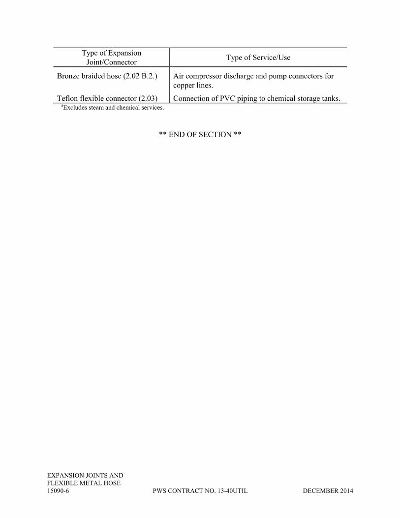
EXPANSION JOINTS AND
FLEXIBLE METAL HOSE
15090-6 PWS CONTRACT NO. 13-40UTIL DECEMBER 2014
Type of Expansion
Joint/Connector Type of Service/Use
Bronze braided hose (2.02 B.2.) Air compressor discharge and pump connectors for
copper lines.
Teflon flexible connector (2.03) Connection of PVC piping to chemical storage tanks. aExcludes steam and chemical services.
** END OF SECTION **

PIPING APPURTENANCES
DECEMBER 2014 PWS CONTRACT NO. 13-40UTIL 15095-1
SECTION 15095
PIPING APPURTENANCES
PART 1 -- GENERAL
1.01 DESCRIPTION
A. SCOPE
This section specifies pipeline thermometers, flow and level gages, pressure gages,
strainers, steam traps, vents and drains.
EXCLUSIONS:
Temperature, pressure and flow measuring devices used for instrumentation are specified
in Division 17. Instruments specified in Section 17211 are identified in the instrument index in
Section 17200.
PART 2 -- PRODUCTS
2.01 PIPELINE THERMOMETERS (NOT USED)
2.02 FLOW AND LEVEL GAGES
A. ROTAMETERS:
Unless otherwise specified, rotameters for purges and other low capacity services shall be
Brooks Sho-Rate "50," Wallace & Tiernan 3-inch purge meter, Schutte & Koerting, or equal,
with integral needle valve and flow controller. Meter tubes shall be glass, floats shall be
stainless steel, and cases shall be aluminum or stainless steel. Unless otherwise specified, meter
sizes shall be selected so that the flow rate recommended by the manufacturer of the purged
equipment falls within the middle third of the meter scale. Units shall have a 3-inch minimum
scale direct reading in the units of flow.
Rotameters for high capacity service shall be glass tube-type with a 5-inch scale and
stainless steel frame. Flow range shall be as specified and scales shall indicate the units of flow.
Rotameters shall be as manufactured by Brooks, Wallace & Tiernan, Schutte & Koerting, or
equal.
Provide adjustable low flow setpoint, activated any time rotameter flow is below setpoint.
Setpoint to be provided either with dry contact output, or external NEMA 4X enclosure with
relay to convert setpoint sensor to a dry contact output. Enclosure to include any required power
supplies, and operate on 120 Volts AC.

PIPING APPURTENANCES
15095-2 PWS CONTRACT NO. 13-40UTIL DECEMBER 2014
B. SIGHT GAGES:
Sight gages shall be 3/4-inch Penberthy 205 Series, Lunkenheimer Fig. 589, or equal,
automatic water gage complete with pyrex gage glass and gage glass protector. Overall length of
gages, type of mounting, and orientation of set shall be as specified.
C. FLOW INDICATORS:
Flow indicators shall be provided where specified. Each indicator shall consist of a
bronze body with threaded ends and a sight glass with rotary wheel. Pressure ratings for flow
indicators shall match pipe pressure ratings. Indicators shall be as manufactured by Jacoby-
Tarbox, Schutte & Koerting, Eugene Ernst Products, or equal.
2.03 PRESSURE DEVICES
A. GAGE COCKS:
Unless otherwise specified, gage cocks shall be Robertshaw 1303, Ashcroft 1095, or
equal. The exposed threads of each gage cock shall be protected by a brass plug.
B. PRESSURE GAGES:
Unless otherwise specified, pressure gage scales shall be selected so that the normal
operating pressure falls between 50 and 80 percent of full scale, shall be 4 1/2-inch, 270-degree
movement, 1/2-percent accuracy, full-scale, and suitable for bottom stem mounting. Gages shall
have a 316-SS bourdon tube. All gages shall have a 300 series stainless steel case, shatterproof
glass, and a 1/2-inch NPT bottom connection.
Pressure gages for air, gas, and low pressure services (0-10 feet) shall be premium grade,
heavy-duty bourdon-tube units (bellow type for vacuum) with Delrin bushings and pinion, and
stainless steel sector.
Gages on liquid service shall be as noted above, except they shall be provided with an
internal pulsation dampening system consisting of either a glycerin fill or a silicone fluid fill.
Snubbers or orifices shall not be utilized. Gages shall be Ashcroft Duragauge Fig. 1279, Ametek
1981L, or equal.
C. DIAPHRAGM SEALS:
Unless otherwise specified, seals shall be diaphragm type with 1/4-inch flushing
connection, Type 316 stainless steel body and Type 316L diaphragm. Fill fluid shall be Silicone
DC200 unless otherwise specified. Seal shall be Mansfield and Green Type SG, Ashcroft Type
101, or equal.

PIPING APPURTENANCES
DECEMBER 2014 PWS CONTRACT NO. 13-40UTIL 15095-3
D. PRESSURE SENSORS
Unless otherwise specified, pressure sensors (tubular chemical seals) shall be the in-line
full stream captive sensing liquid type. Wetted parts shall be 316 stainless steel. Flexible
cylinder shall be Buna-N unless otherwise specified. Seals shall be rated for 200 psi with 5-inch
SC hysteresis. Seals shall be Ronningen-Petter, Red Valve, or equal.
Fill fluid shall be rated for a temperature range of -20 degrees F to 200 degrees F.
Capillary tubing shall be armored stainless steel. Fittings shall be provided for vacuum filling of
system. Systems that are not factory filled shall be vacuum filled in the field. Filling
connections shall be soldered shut after vacuum evacuation and filling.
2.04 STRAINERS
A. AIR STRAINERS:
Unless otherwise specified, air strainers shall be Y-pattern, cast iron body, with 40 mesh
Monel screens packed with Everdur wool. Bronze bodies shall be provided with copper piping.
Air line strainers shall be fitted with a brass blowoff cock. Strainers shall be Mueller,
Armstrong, or equal.
B. WATER STRAINERS:
Water strainers shall be of Y-pattern, unless otherwise specified. Water strainers shall
have cast iron body. Bronze bodies shall be provided with copper piping. Strainers shall have
304 stainless steel screens and tapped and plugged blowoff connections. Screen perforations
shall be 0.045 inch for water service. Strainers shall be Mueller, Armstrong, or equal.
C. FUEL OIL STRAINERS:
Fuel oil strainers shall be of the basket type and shall have cast iron body with 304
stainless steel screens. Screen perforation shall be 3/64 inch. Strainers shall be Bailey No. 1,
Mueller, or equal.
2.05 STEAM TRAPS (NOT USED)
2.06 PRODUCT DATA
Manufacturer's product data shall be provided in accordance with Section 01300.

PIPING APPURTENANCES
15095-4 PWS CONTRACT NO. 13-40UTIL DECEMBER 2014
PART 3 -- EXECUTION
3.01 PIPELINE THERMOMETERS (NOT USED)
3.02 GAGE TAPS
Gage taps shall be provided on the suction and discharge of pumps, fans, compressors,
vacuum pumps and blowers. Gage taps shall consist of a 1/4-inch gage cock attached by a
threaded nipple to the pipeline, duct or equipment.
3.03 VENTS AND DRAINS
Manual air vents shall be provided at the high points of each reach of pipeline where
specified. Air vents shall consist of bronze cock and copper tubing return. Air vents shall be
taken to the nearest floor with cock mounted 4 feet above the floor. Vents in piping systems for
fluids containing solids shall be 1-inch nonlubricated eccentric plug valves fitted with quick
couplers.
Drains shall be piped to a sump, gutter, floor drain or other collection point with a valve
mounted 4 feet above the floor. Drain valves shall be threaded end gate valves of the size
specified. When drains cannot be run to collection points, they shall be routed to a point of easy
access and shall have hose gate valves of the size specified.
** END OF SECTION **

PIPE HANGERS
AND SUPPORTS
DECEMBER 2014 PWS CONTRACT NO. 13-40UTIL 15096-1
SECTION 15096
PIPE HANGERS AND SUPPORTS
PART 1 -- GENERAL
1.01 DESCRIPTION
A. SCOPE:
This section specifies hangers and supports for all piping systems specified in Section
15050. This section does not include pipe supports for fire sprinkler systems, pipe anchors,
guides or seismic restraints.
B. OPERATING CONDITIONS:
The hangers and supports specified in this section are provided to resist pipe loads
occurring primarily in the downward (gravity) direction. For the purpose of pipe hanger and
support selection, this section establishes pipe support classifications based on the operating
temperatures of the piping contents. Pipe support classifications are as follows:
1. Hot Systems:
a. A - 1. 120 degrees F to 450 degrees F
b. A - 2. 451 degrees F to 750 degrees F
c. A - 3. Over 750 degrees F
2. Ambient Systems
a. 50 degrees F to 119 degrees F
3. Cold Systems
a. C - 1. 33 degrees F to 59 degrees F
b. C - 2. -20 degrees F to 32 degrees F
C. HANGER AND SUPPORT SELECTION:
The Contractor shall select pipe hangers and supports as specified in the Contract
Drawings. Selections shall be based upon the pipe support classifications specified in this
section, the piping insulation thickness specified in Section 15250, and any special requirements
which may be specified in the project manual.

PIPE HANGERS
AND SUPPORTS
15096-2 PWS CONTRACT NO. 13-40UTIL DECEMBER 2014
The Contractor shall review the piping layout in relation to the surrounding structure and
adjacent piping and equipment before selecting the type of support to be used at each hanger
point.
Hangers and supports shall withstand all static and specified dynamic conditions of
loading to which the piping and associated equipment may be subjected. As a minimum,
consideration shall be given to the following conditions:
1. Weights of pipe, valves, fittings, insulating materials, suspended hanger
components, and normal fluid contents.
2. Weight of hydrostatic test fluid or cleaning fluid if normal operating fluid
contents are lighter.
3. Reaction forces due to the operation of safety or relief valves.
4. Wind, snow or ice loadings on outdoor piping.
Hangers and supports shall be sized to fit the outside diameter of pipe, tubing, or, where
specified, the outside diameter of insulation.
Where negligible movement occurs at hanger locations, rod hangers shall be used for
suspended lines, wherever practical. For piping supported from below, bases, brackets or
structural cross members shall be used.
Hangers for the suspension of size 2 1/2 inches and larger pipe and tubing shall be
capable of vertical hanger component adjustment under load.
The supporting systems shall provide for and control the free or intended movement of
the piping including its movement in relation to that of connected equipment.
Where there is horizontal movement at a suspended type hanger location, hanger
components shall be selected to allow for swing. The vertical angle of the hanger rod shall not,
at any time, exceed 4 degrees.
There shall be no contact between a pipe and hanger or support component of dissimilar
metals. Prevent contact between dissimilar metals when supporting copper tubing by use of
copper-plated, rubber, plastic or vinyl coated, or stainless steel hanger and support components.
Unless otherwise specified, existing pipes and supports shall not be used to support new
piping.
Unless otherwise specified, pipe support components shall not be attached to pressure
vessels.
Stock hanger and support components shall be used wherever practical.

PIPE HANGERS
AND SUPPORTS
DECEMBER 2014 PWS CONTRACT NO. 13-40UTIL 15096-3
1.02 REFERENCES
This section contains references to the following documents. They are a part of this
section as specified and modified. Where a referenced document contains references to other
standards, those documents are included as references under this section as if referenced directly.
In the event of conflict between the requirements of this section and those of the listed
documents, the requirements of this section shall prevail.
Unless otherwise specified, references to documents shall mean the documents in effect at
the time of Advertisement for Bids or Invitation to Bid (or on the effective date of the Agreement
if there were no Bids). If referenced documents have been discontinued by the issuing
organization, references to those documents shall mean the replacement documents issued or
otherwise identified by that organization or, if there are no replacement documents, the last
version of the document before it was discontinued. Where document dates are given in the
following listing, references to those documents shall mean the specific document version
associated with that date, regardless of whether the document has been superseded by a version
with a later date, discontinued or replaced.
Reference Title
AISC Manual of Steel
Construction
American Institute of Steel Construction, Manual of
Steel Construction, Allowable Stress Design - 9th Ed.
FEDSPEC WW-H-171e-78 Hangers and Supports, Pipe
MFMA-2-91 Metal Framing Standards Publication
MSS SP-69-91 Pipe Hangers and Supports - Selection and Application
MSS SP-58-93 Pipe Hangers and Supports - Materials, Design and
Manufacture
PART 2 -- PRODUCTS
2.01 ACCEPTABLE PRODUCTS
Standard pipe supports and components shall be manufactured by B-Line, Carpenter &
Patterson, Kin-Line, Grinnell, Michigan, Pipe Shields Incorporated, Superstrut, Unistrut, or
equal. Pipe support components shall conform to the requirements of MSS SP-69 and
FEDSPEC WW-H-171e. Pipe support materials shall conform to the requirements of MSS SP-
58. Metal framing system components shall conform to the metal framing manufacturers'
Association Standard MFMA-2.

PIPE HANGERS
AND SUPPORTS
15096-4 PWS CONTRACT NO. 13-40UTIL DECEMBER 2014
2.02 MATERIALS
A. GENERAL:
Unless otherwise specified, pipe hangers and supports, structural attachments, fittings and
accessories shall be hot-dip or mechanically galvanized after fabrication. Nuts, bolts and
washers may be zinc-plated except for those subject to moisture or corrosive atmosphere, as
specified in paragraph 16000-1.05 B, which shall be type 304 stainless steel.
B. PIPE HANGERS AND SUPPORTS:
1. TYPE 1 – CLEVIS PIPE HANGER: Clevis hangers shall be carbon steel
with configuration and components equivalent to MSS and FEDSPEC Type 1.
a. STEEL PIPE (INSULATED): shall be B-Line B3100, Grinnell
Fig. 260, or equal, with insulation shield.
b. STEEL PIPE (UNINSULATED): shall be B-Line B3100, Grinnell
Fig. 260, or equal.
c. CAST AND DUCTILE IRON PIPE: shall be B-Line B3102,
Grinnell Fig. 590, or equal.
d. COPPER PIPE (UNINSULATED): shall be B-Line B3104 CT,
Grinnell Fig. CT-65, or equal.
e. COPPER PIPE (INSULATED): shall be B-Line B3100, Grinnell
Fig. 260, or equal, with insulation shield.
f. PLASTIC PIPE: shall be B-Line B3100 C, Carpenter & Patterson
Fig. 100PVC, or equal.
2. TYPE 2 – “J” PIPE HANGER: Hangers shall be carbon steel with
configuration and components equivalent to MSS Type 5.
a. STEEL PIPE: shall be B-Line B3690, Grinnell Fig. 67, Michigan
model 418, or equal.
b. COPPER AND PLASTIC PIPE: shall be Michigan model 419,
Unistrut J 1205N series, or equal.
3. TYPE 3 – DOUBLE BOLT PIPE CLAMP: Pipe clamp shall be carbon
steel, with configuration and components equivalent to MSS and FEDSPEC Type 3.

PIPE HANGERS
AND SUPPORTS
DECEMBER 2014 PWS CONTRACT NO. 13-40UTIL 15096-5
a. STEEL PIPE (INSULATED): shall be B-Line B3144, Grinnell
Fig. 295, or equal, with insulation shield. Insulation shield is optional for hot and ambient
systems.
b. STEEL PIPE (UNINSULATED): shall be B-Line B3144, Grinnell
Fig. 295, or equal.
c. COPPER PIPE (INSULATED ONLY): shall be B-Line B3144,
Grinnell Fig. 295, or equal, with insulation shield.
4. TYPE 4 – ADJUSTABLE ROLLER HANGER: Rollers shall be cast iron,
yoke and cross bolt shall be carbon steel. Configuration and components shall be equivalent to
MSS Type 43 and FEDSPEC Type 44.
a. STEEL PIPE (INSULATED): shall be B-Line B3110, Grinnell Fig.
181, or equal, with insulation shield.
b. STEEL PIPE (UNINSULATED): shall be B-Line B3110, Grinnell
Fig. 181, or equal.
c. COPPER PIPE (INSULATED ONLY): shall be B-Line B3110,
Grinnell Fig. 181, or equal, with insulation shield.
d. PLASTIC PIPE:- shall be B-Line B3110, Grinnell Fig. 181, or
equal.
5. TYPE 5 – SINGLE PIPE ROLL: Rollers and sockets shall be cast iron,
cross rod shall be steel. Configuration and components shall be equivalent to MSS Type 41 and
FEDSPEC Type 42.
a. STEEL PIPE (INSULATED): shall be B-Line B3114, Grinnell
Fig. 171, or equal, with insulation shield.
b. STEEL PIPE (UNINSULATED): shall be B-Line B3114, Grinnell
Fig. 171, or equal.
c. PLASTIC PIPE: shall be B-Line B3114, Grinnell Fig. 171, or
equal.
6. TYPE 6 - FRAMING CHANNEL PIPE CLAMP: Pipe clamps shall be
steel with galvanized finish and material thickness as listed below:
a. STEEL PIPE (UNINSULATED): Pipe size 3/8 inch and 1/2 inch
shall be 16 gage; 3/4 inch through 1 1/4 inches shall be 14 gage; 1 1/2 inches through 3 inches
shall be 12 gage; 3 1/2 inches through 5 inches shall be 11 gage; 6 and 8 inches shall be 10 gage;
Michigan model 431, Powerstrut PS 1100, Unistrut P 1109 series, or equal.

PIPE HANGERS
AND SUPPORTS
15096-6 PWS CONTRACT NO. 13-40UTIL DECEMBER 2014
b. STEEL PIPE (INSULATED): Pipe clamp shall be as described in
paragraph 15096-2.02 B.6.a with insulation shield.
c. COPPER (UNINSULATED) AND PLASTIC PIPE: Pipe size
3/8 inch and 1 inch shall be 16 gage; 1-1/4 inches and 1-1/2 inches shall be 14 gage; 2 inches
through 3 inches shall be 12 gage; 4 inches shall be 11 gage; clamp shall be copper-plated, plastic
coated or lined with dielectric material; Michigan model 432, Powerstrut PS 1200, Unistrut P
2024C and P 2024PC series, or equal.
d. COPPER PIPE (INSULATED): Pipe clamp shall be as described
in paragraph 15096-2.02 B.6.a with insulation shield.
7. TYPE 7 - U-BOLT: U-bolts shall be carbon steel with configuration
equivalent to MSS and FEDSPEC Type 24.
a. STEEL PIPE (UNINSULATED): shall be Grinnell Fig. 137, B-
Line B3188, or equal.
b. STEEL PIPE (INSULATED): shall be Grinnell Fig. 137, B-Line
B3188, or equal, with insulation shield.
c. CAST AND DUCTILE IRON PIPE: shall be Grinnell Fig. 137, B-
Line B3188, or equal.
d. COPPER PIPE (UNINSULATED): shall be Carpenter &
Patterson Fig. 222 CT, B-Line B3501 CT, Grinnell Fig. 137C, or equal.
e. COPPER PIPE (INSULATED): shall be Grinnell Fig. 137, B-Line
B3188, or equal, with insulation shield.
f. PLASTIC PIPE: shall be Grinnell Fig. 137C, Michigan model 151,
B-Line B3188 C, or equal.
8. TYPE 8 - ADJUSTABLE PIPE ROLL SUPPORT: Rollers and sockets
shall be cast iron, cross rod and support rods shall be carbon steel.
a. STEEL PIPE (INSULATED): shall be B-Line B3122, Grinnell
Fig. 177, or equal, with insulation shield.
b. STEEL PIPE (UNINSULATED): shall be B-Line B3122, Grinnell
Fig. 177, or equal.
c. COPPER PIPE (INSULATED ONLY): shall be B-Line B3122,
Grinnell Fig. 177, or equal, with insulation shield.

PIPE HANGERS
AND SUPPORTS
DECEMBER 2014 PWS CONTRACT NO. 13-40UTIL 15096-7
d. PLASTIC PIPE: shall be B-Line B3122, Grinnell Fig. 177, or
equal.
9. TYPE 9 - WELDED PIPE STANCHION: Minimum material thickness
shall be standard schedule carbon steel pipe, cut to match contour of the pipe elbow. Use of this
support shall be limited to ambient systems only.
10. TYPE 10 - PIPE STANCHION SADDLE: Saddles and yokes shall be
carbon steel and comply with MSS Type 37 and FEDSPEC Type 38.
a. STEEL PIPE (INSULATED): shall be Carpenter & Patterson Fig.
125, B-Line B3090, or equal, with insulation shield.
b. STEEL PIPE (UNINSULATED): shall be Carpenter & Patterson
Fig. 125, B-Line B3090, or equal.
c. CAST AND DUCTILE IRON PIPE:- shall be Carpenter &
Patterson Fig. 125, B-Line B3090 NS, or equal.
d. COPPER PIPE (UNINSULATED): shall be Carpenter &
Patterson Fig. 125, B-Line B3090, or equal, with insulation shield or lined with dielectric
material.
e. COPPER PIPE (INSULATED): shall be Carpenter & Patterson
Fig. 125, B-Line B3090, or equal, with insulation shield.
f. PLASTIC PIPE: shall be Carpenter & Patterson Fig. 125, B-Line
B3090, or equal.
11. TYPE 11 - OFFSET PIPE CLAMP: Pipe clamp shall be carbon steel with
configuration and components as specified and shall be of standard design manufactured by a pipe
hanger component manufacturer.
a. STEEL PIPE (INSULATED): shall be B-Line B3148, Grinnell
Fig. 103, or equal, with insulation shield.
b. STEEL PIPE (UNINSULATED): shall be B-Line B3148, Grinnell
Fig. 103, or equal.
c. CAST AND DUCTILE IRON PIPE:- shall be B-Line B3148 NS,
Grinnell Fig. 103, or equal.
d. COPPER PIPE (INSULATED): shall be B-Line B3148, Grinnell
Fig. 103, or equal, with insulation shield.

PIPE HANGERS
AND SUPPORTS
15096-8 PWS CONTRACT NO. 13-40UTIL DECEMBER 2014
e. COPPER PIPE (UNINSULATED): shall be B-Line B3148,
Grinnell Fig. 103, or equal, lined with dielectric material.
f. PLASTIC PIPE: shall be B-Line B3148, Grinnell Fig. 103, or
equal.
Vertical pipe support applications shall be as specified above except that
insulation shields shall not be used for insulated pipe.
12. TYPE 12 - RISER CLAMP: Riser clamp shall be carbon steel with
configuration and components equivalent to MSS and FEDSPEC Type 8.
a. STEEL PIPE (INSULATED): shall be B-Line B3373, Grinnell
Fig. 261, or equal.
b. STEEL PIPE (UNINSULATED): shall be B-Line B3373, Grinnell
Fig. 261, or equal.
c. CAST AND DUCTILE IRON PIPE: shall be B-Line B3373,
Grinnell Fig. 261, or equal.
d. COPPER PIPE (INSULATED): shall be B-Line B3373 CT,
Grinnell Fig. CT-121, Michigan model 511, or equal.
e. COPPER PIPE (UNINSULATED): shall be B-Line B3373 CT,
Grinnell Fig. CT-121, Michigan model 511, or equal.
f. PLASTIC PIPE: shall be B-Line B3373, Grinnell Fig. 261c, or
equal.
13. TYPE 13 - FRAMING CHANNEL PIPE STRAP: Pipe strap shall be
carbon steel, with configuration equivalent to MSS Type 26.
a. STEEL PIPE (UNINSULATED): shall be Superstrut No. C-708-
U, Powerstrut PS 3126, Kin-Line No. 477, or equal.
b. STEEL PIPE (INSULATED): shall be Superstrut No. C-708-U,
Powerstrut PS 3126, Kin-Line No. 477, or equal, with insulation shield.
c. COPPER PIPE (UNINSULATED): shall be Superstrut No. C-
708-U, Powerstrut PS 3126, Kin-Line No. 477, or equal, with insulation shield or lined with
dielectric material.
d. COPPER PIPE (INSULATED): shall be Superstrut No. C-708-U,
Powerstrut PS 3126, Kin-Line No. 477, or equal, with insulation shield.

PIPE HANGERS
AND SUPPORTS
DECEMBER 2014 PWS CONTRACT NO. 13-40UTIL 15096-9
e. PLASTIC PIPE:- shall be Superstrut No. C-708-U, Powerstrut PS
3126, Kin-Line No. 477, or equal.
C. RACK AND TRAPEZE SUPPORTS:
1. GENERAL: Unless otherwise specified, trapeze and pipe rack components
shall have a minimum steel thickness of 12 gage, with a maximum deflection 1/240 of the span.
2. TYPE 20 - TRAPEZE PIPE SUPPORT: Trapeze pipe support cross
members shall be framing channel as specified in paragraph 15096-2.02 E.5. Flat plate fittings
shall be 1 5/8-inch square carbon steel of standard design manufactured by framing channel
manufacturer, Unistrut P2471, B-Line B202-2, or equal.
3. TYPE 21 - PIPE RACK SUPPORT: Post and cross members shall be
framing channel as specified in paragraph 15096-2.02 E.5. Pipe rack fittings shall be carbon
steel, of standard design manufactured by framing channel manufacturer. 90-degree fittings shall
be gusseted Unistrut P2484, B-Line B844, or equal. Post base fittings shall be as specified in
paragraph 15096-2.02 D.5.
D. STRUCTURAL ATTACHMENTS:
1. TYPE A - MALLEABLE IRON CONCRETE INSERT: Concrete inserts
shall be malleable iron and comply with MSS and FEDSPEC Type 18. Grinnell Fig. 282,
Carpenter & Patterson Fig. 108, or equal.
2. TYPE B - SIDE BEAM BRACKET: Bracket shall be malleable iron and
comply with MSS Type 34 and FEDSPEC Type 35. Grinnell Fig. 202, B-Line B3062, or equal.
3. TYPE C - MALLEABLE BEAM CLAMP WITH EXTENSION PIECE:
Clamp and extension piece shall be malleable iron, tie rod shall be steel. Beam clamp shall
comply with MSS and FEDSPEC Type 30. Grinnell Fig. 218 with Fig. 157 extension piece, B-
Line B3054, or equal.
4. TYPE D - STEEL BEAM CLAMP WITH EYE NUT: Beam clamp and
eye nut shall be forged steel. Configuration and components shall comply with MSS and
FEDSPEC Type 28. Grinnell Fig. 292, Carpenter & Patterson Fig. 297, or equal.
5. TYPE E - FRAMING CHANNEL POST BASE: Post bases shall be
carbon steel, of standard design manufactured by framing channel manufacturer. Single channel:
Unistrut P2072A, B-Line B280, or equal. Double channel: Unistrut P2073A, B-Line B281, or
equal.
6. TYPE F - WELDED BEAM ATTACHMENT: Beam attachment shall be
carbon steel and comply with MSS and FEDSPEC Type 22. B-Line B3083, Grinnell Fig. 66, or
equal.

PIPE HANGERS
AND SUPPORTS
15096-10 PWS CONTRACT NO. 13-40UTIL DECEMBER 2014
7. TYPE G - WELDED STEEL BRACKET: Bracket shall be carbon steel
and comply with MSS Type 32 and FEDSPEC Type 33 for medium welded bracket. Heavy
welded bracket shall comply with MSS Type 33 and FEDSPEC Type 34.
8. TYPE H - CAST IRON BRACKET: Bracket shall be cast iron, Carpenter
& Patterson Fig. 340, or equal.
9. TYPE J - ADJUSTABLE BEAM ATTACHMENT: Beam attachment
shall be carbon steel, Carpenter & Patterson Fig. 151, B-Line B3082, or equal.
10. TYPE K - DOUBLE CHANNEL BRACKET: Wall channel shall be
single channel framing channel as specified in paragraph 15096-2.02 E.5. Cantilever bracket
shall be a carbon steel double framing channel assembly, Unistrut P2542 through P2546, B-Line
B297-12 through B297-36, or equal.
11. TYPE L - SINGLE CHANNEL BRACKET: Wall channel shall be single
channel framing channel as specified in paragraph 15096-2.02 E.5. Cantilever bracket shall be a
carbon steel single framing channel assembly, Unistrut P2231 through P2234, B-Line B198-6,
B198-12, B196-18 and B196-24, or equal.
12. TYPE M - WALL MOUNTED CHANNEL: Wall channel shall be single
channel framing channel as specified in paragraph 15096-2.02 E.5.
13. TYPE N - PIPE STANCHION FLOOR ATTACHMENT: Baseplate shall
be carbon steel with 1/2 inch minimum thickness. Anchor bolt holes shall be 1/16 inch larger than
the anchor bolt diameter. The space between the baseplate and the floor shall be filled with
nonshrink grout.
E. ACCESSORIES:
1. HANGER RODS: Rods shall be carbon steel, threaded on both ends or
continuous threaded and sized as specified.
2. WELDLESS EYE NUT: Eye nut shall be forged steel and shall comply
with MSS and FEDSPEC Type 17. Eye nut shall be Grinnell Fig. 290, B-Line B3200, or equal.
3. WELDED EYE ROD: Eye rod shall be carbon steel with eye welded
closed. Inside diameter of eye shall accommodate a bolt diameter 1/8 inch larger than the rod
diameter. Eye rod shall be Grinnell Fig. 278, B-Line B3211, or equal.
4. TURNBUCKLE: Turnbuckle shall be forged steel and shall comply with
MSS and FEDSPEC Type 13. Turnbuckle shall be Grinnell Fig. 230, B-Line B3202, or equal.

PIPE HANGERS
AND SUPPORTS
DECEMBER 2014 PWS CONTRACT NO. 13-40UTIL 15096-11
5. FRAMING CHANNEL: Framing channel shall be 1 5/8 inches square,
roll formed, 12-gage carbon steel. Channel shall have a continuous slot along one side with in-
turned clamping ridges. Single channel: Unistrut P1000, B-Line B22, or equal. Double channel:
Unistrut P1001, B-Line B22A, or equal. Triple channel: Unistrut P1004A, B-Line B22X, or equal.
2.03 THERMAL PIPE HANGER SHIELD
Thermal shields shall be provided at hanger, support and guide locations on pipe
requiring insulation. The shield shall consist of an insulation layer encircling the entire
circumference of the pipe and a steel jacket encircling the insulation layer. The thermal shield
shall be the same thickness as the piping system insulation specified in Section 15250. The
standard shield shall be used for hot systems and the vapor barrier shield shall be used for cold
systems. Stainless steel band clamps shall be used where specified to ensure against slippage
between the pipe wall and the thermal shield.
A. STANDARD SHIELD:
1. INSULATION:
a. Hydrous calcium silicate, high density, waterproof
b. Compressive strength: 100 psi average
c. Flexural strength: 75 psi average
d. K factor: 0.38 at 100 degrees F mean
e. Temperature range: 20 degrees F to 500 degrees F
2. STEEL JACKET: Galvanized steel. Gage shall be the manufacturer's
standard supplied for the given pipe size.
3. CONNECTION: Shield shall have butt connection to pipe insulation. Steel
jacket and insulation shall be flush with end.
B. VAPOR BARRIER SHIELD:
1. INSULATION:
a. Hydrous calcium silicate, high density, waterproof
b. Compressive strength: 100 psi average
c. Flexural strength: 75 psi average
d. K factor: 0.38 at 100 degrees F mean
e. Temperature range: 20 degrees F to 500 degrees F
2. STEEL JACKET: Galvanized steel. Gage shall be the manufacturer's
standard supplied for the given pipe size.

PIPE HANGERS
AND SUPPORTS
15096-12 PWS CONTRACT NO. 13-40UTIL DECEMBER 2014
3. CONNECTION: Shield shall have butt connection to pipe insulation.
Insulation shall extend 1 inch each side of steel jacket for vaportight connection to pipe insulation
vapor barrier.
2.04 PRODUCT DATA
Hanger and support locations and components shall be indicated on the piping layout
drawings required by paragraph 15050-2.04.
PART 3 -- EXECUTION
3.01 HANGER AND SUPPORT LOCATIONS
The Contractor shall locate hangers and supports as near as possible to concentrated loads
such as valves, flanges, etc. Locate hangers, supports and accessories within the maximum span
lengths specified in the Contract Drawings to support continuous pipeline runs unaffected by
concentrated loads. The contract drawings show the general location of major pipe, ductwork,
valve, and equipment supports. Each and every required location of aforementioned supports are
not shown on the contract drawings. The Contractor is responsible for the adequate support and
seismic bracing of all piping, ductwork, valves and equipment in accordance with Section 15097.
The Contractor shall employ the services of a licensed California structural engineer to approve
all necessary aforementioned support systems and include this information with the shop
drawings.
At least one hanger or support shall be located within 2 feet from a pipe change in
direction.
The Contractor shall locate hangers and supports to ensure that connections to equipment,
tanks, etc., are substantially free from loads transmitted by the piping.
Where piping is connected to equipment, a valve, piping assembly, etc., that will require
removal for maintenance, the piping shall be supported in such a manner that temporary supports
shall not be necessary for this procedure.
Pipe shall not have pockets formed in the span due to sagging of the pipe between
supports caused by the weight of the pipe, medium in the pipe, insulation, valves and fittings.
3.02 INSTALLATION
Welded and bolted attachments to the building structural steel shall be in accordance with
the requirements of the AISC Manual of Steel Construction. Unless otherwise specified, there
shall be no drilling or burning of holes in the building structural steel.
Hanger components shall not be used for purposes other than for which they were
designed. They shall not be used for rigging and erection purposes.

PIPE HANGERS
AND SUPPORTS
DECEMBER 2014 PWS CONTRACT NO. 13-40UTIL 15096-13
The Contractor shall install items to be embedded before concrete is poured. Fasten
embedded items securely to prevent movement when concrete is poured.
Embedded anchor bolts shall be used instead of concrete inserts for support installations
in areas below water surface or normally subject to submerging.
The Contractor shall install thermal pipe hanger shields on insulated piping at required
locations during hanger and support installation. Butt joint connections to pipe insulation shall
be made at the time of insulation installation in accordance with the manufacturer's
recommendations.
Hanger and support components in contact with plastic pipe shall be free of burrs and
sharp edges.
Rollers shall roll freely without binding.
Finished floor beneath Type N structural attachments and framing channel post bases
shall be roughed prior to grouting. Grout between base plate and floor shall be free of voids and
foreign material.
Baseplates shall be cut and drilled to specified dimensions prior to welding stanchions or
other attachments and prior to setting anchor bolts.
Plastic or rubber end caps shall be provided at the exposed ends of all framing channels
that are located up to 7 feet above the floor.
3.03 ADJUSTMENTS
The Contractor shall adjust hangers and supports to obtain required pipe slope and
elevation. Shims made of material that is compatible with the piping material may be used.
Stanchions shall be adjusted prior to grouting their baseplates.
** END OF SECTION **
PIPE HANGERS
AND SUPPORTS
15096-14 PWS CONTRACT NO. 13-40UTIL DECEMBER 2014
THIS PAGE INTENTIONALLY LEFT BLANK

VALVES, GENERAL
DECEMBER 2014 PWS CONTRACT NO. 13-40UTIL 15100-1
SECTION 15100
VALVES, GENERAL
PART 1 -- GENERAL
1.01 WORK OF THIS SECTION
The WORK of this Section includes providing general requirements for valves including
epoxy coating, installing, adjusting, and testing of valves and where buried valves are indicated,
valve boxes to grade, with covers, stem extensions, and position indicators.
1. Section 15101 Gate Valves
2. Section 15102 Resilient-Seated Gate Valves
3. Section 15103 Butterfly Valves
4. Section 15110 Eccentric Plug Valves
5. Section 15118 Spring-loaded Swing Check Valves
6. Section 15129 Full-Port Ball Valves
7. Section 15151 Air Release and Vacuum Valves
1.02 SPECIFICATIONS AND STANDARDS
Except as otherwise indicated, the current editions of the following standards apply to the
WORK of this Section:
Reference Title
ANSI B16.1 Cast Iron Pipe Flanges and Flanged Fittings, Class 25,
125, 250, and 800
ANSI B16.5 Pipe Flanges and Flanged Fittings, Steel Nickel Alloy
and Other Special Alloys
ANSI/ASME B1.20.1 General Purpose Pipe Threads (Inch)
ANSI/ASME B31.1 Power Piping
ASTM A 36 Specification for Structural Steel
ASTM A 48 Specification for Gray Iron Castings
ASTM A 126 Specification for Gray Iron Castings for Valves, Flanges,
and Pipe Fittings
ASTM A 536 Specification for Ductile Iron Castings
ASTM B 61 Specification for Steam or Valve Bronze Castings
ASTM B 62 Specification for Composition Bronze or Ounce Metal
Castings

VALVES, GENERAL
15100-2 PWS CONTRACT NO. 13-40UTIL DECEMBER 2014
Reference Title
ASTM B 148 Specification for Aluminum-Bronze Castings
ASTM B 584 Specification for Copper Alloy Sand Castings for
General Applications
ANSI/AWWA C500 Gate Valves for Water and Sewerage Systems
ANSI/AWWA C502 Dry-Barrel Fire Hydrants
ANSI/AWWA C503 Wet-Barrel Fire Hydrants
ANSI/AWWA C504 Rubber-Seated Butterfly Valves
ANSI/AWWA C506 Backflow Prevention Devices - Reduced Pressure
Principle and Double Check Valve Types
ANSI/AWWA C507 Ball Valves 6 Inches Through 48 Inches
AWWA C508 Swing-Check Valves for Waterworks Service, 2 Inches
Through 24 Inches NPS
ANSI/AWWA C509 Resilient-Seated Gate Valves for Water and Sewage
Systems
AWWA C550 Protective Interior Coatings for Valves and Hydrants
SSPC-SP-2 Hand Tool Cleaning
SSPC-SP-5 White Metal Blast Cleaning
1.03 SHOP DRAWINGS AND SAMPLES
The following shall be submitted in compliance with Section 01300:
1. Manufacturer's product data including catalogue cuts.
2. Manufacturer's installation instructions.
3. Shop drawings showing details and dimensions.
4. Manufacturer's certification that products comply with the indicated
requirements.
5. Schedule of valves indicating valve identification and location.
6. Manufacturer's certification that epoxy coatings have been factory tested
and comply with the indicated requirements.

VALVES, GENERAL
DECEMBER 2014 PWS CONTRACT NO. 13-40UTIL 15100-3
1.05 OWNER'S MANUAL
The following shall be included in the OWNER'S MANUAL in compliance with Section
01730:
1. Manufacturer's installation and operating instructions.
2. Manufacturer's maintenance procedures.
3. List of special tools.
4. Schedule of valves indicating valve identification and location.
1.06 FACTORY TESTING
A. GENERAL:
Valves shall be tested in compliance with the AWWA Standards as indicated. Except as
otherwise indicated, each valve body shall be tested under a test pressure equal to twice its design
water-working pressure.
B. PROOF-OF-DESIGN TESTS:
The CONTRACTOR shall furnish the CONSTRUCTION MANAGER three (3) certified
copies of a report from an independent testing laboratory certifying successful completion of
proof-of-design testing for all valves of sizes 10-inch and larger unless indicated otherwise in the
specific valve Section. In lieu of testing the valves at an independent testing laboratory, proof-of-
design testing may be performed at the valve manufacturer's laboratory, but must be witnessed by
a representative of a qualified independent testing laboratory representative. Proof-of-design
testing shall have been performed on not less than three valves, with all three units demonstrating
full compliance with the test standards. Failure to satisfactorily complete the test shall be
deemed sufficient evidence to reject all valves of the proposed make or manufacturer's model
number.
1.07 FIELD TESTING
Valves shall be field-tested for compliance with the indicated requirements.
PART 2 -- PRODUCTS
2.01 VALVES
A. GENERAL:
Shut-off valves, 6-inch and larger, shall have operators with position indicators. Where
buried, these valves shall be provided with valve boxes and covers containing position indicators,

VALVES, GENERAL
15100-4 PWS CONTRACT NO. 13-40UTIL DECEMBER 2014
and valve extensions. Valves mounted higher than 7 feet above working level shall be provided
with chain operators.
B. GATE VALVE STEMS:
Where dezincification is indicated, gate valve stems shall be fabricated with bronze
conforming to ASTM B 62, containing not more than 5 percent of zinc nor more than 2 percent
of aluminum. Gate valve stems shall be designed for minimum tensile strength of 60,000 psi,
minimum yield strength of 40,000 psi, and an elongation of at least 10 percent in 2 inches, as
determined by a test coupon poured from the same ladle from which the valve stems are poured.
Where dezincification is not indicated, bronze conforming to ASTM B 584 may be used.
C. PROTECTIVE COATING:
Except where otherwise indicated, ferrous surfaces, exclusive of stainless steel surfaces,
in the water passages of all valves 4-inch and larger, and exterior surfaces of submerged valves,
shall be epoxy coated. Flange faces of valves shall not be epoxy coated.
D. VALVE OPERATORS:
Where indicated, valves shall include electric operators recommended by the
manufacturer. Operators of the same type shall be furnished by the same manufacturer. Valve
operators, regardless of type, shall be installed, adjusted, and tested by the valve manufacturer at
the manufacturing plant.
E. NUTS AND BOLTS:
Nuts and bolts on valve flanges, bodies and supports shall comply with Section 15085-
2.01C.
2.02 NAMEPLATES, TOOLS AND SPARE PARTS
A. NAMEPLATES:
Except as otherwise indicated, a label shall be provided on all valves exclusive of hose
bibbs and chlorine cylinder valves. The label shall be 1/16-inch plastic or stainless steel,
minimum 2 inches by 4 inches in size, and shall be permanently attached to the valve.
B. SPARE PARTS:
Two sets of packings, O-rings, gaskets, discs, seats, and bushings shall be furnished with
each valve, as applicable.

VALVES, GENERAL
DECEMBER 2014 PWS CONTRACT NO. 13-40UTIL 15100-5
PART 3 -- EXECUTION
3.01 VALVE INSTALLATION
A. GENERAL:
Valves, operating units, stem extensions, valve boxes, and accessories shall be installed
in accordance with the manufacturer's installation instructions. Valves shall be independently
supported to prevent stresses on the pipe.
B. ACCESS:
Valves shall be installed to provide easy access for operation, removal, and maintenance
and to prevent interferences between valve operators and structural members or handrails.
C. VALVE ACCESSORIES:
Where combinations of valves, sensors, switches, and controls are indicated, the
combinations shall be properly assembled and installed to ensure that systems are compatible and
operating properly.
** END OF SECTION **
VALVES, GENERAL
15100-6 PWS CONTRACT NO. 13-40UTIL DECEMBER 2014
THIS PAGE INTENTIONALLY LEFT BLANK

GATE VALVES
DECEMBER 2014 PWS CONTRACT NO. 13-40UTIL 15101-1
SECTION 15101
METAL SEATED GATE VALVES
PART 1 -- GENERAL
1.01 DESCRIPTION
This section specifies bronze and iron-body, solid-wedge gate valves. Iron body valves
shall be bronze mounted.
1.02 QUALITY ASSURANCE
A. REFERENCES:
This section contains references to the following documents. They are a part of this
section as specified and modified. Where a referenced document contains references to other
standards, those documents are included as references under this section as if referenced directly.
In the event of conflict between the requirements of this section and those of the listed
documents, the requirements of this section shall prevail.
Unless otherwise specified, references to documents shall mean the documents in effect
at the time of Advertisement for Bids or Invitation to Bid (or on the effective date of the
Agreement if there were no Bids). If referenced documents have been discontinued by the
issuing organization, references to those documents shall mean the replacement documents
issued or otherwise identified by that organization or, if there are no replacement documents, the
last version of the document before it was discontinued. Where document dates are given in the
following listing, references to those documents shall mean the specific document version
associated with that date, regardless of whether the document has been superseded by a version
with a later date, discontinued or replaced.
Reference Title
ANSI B16.1 Cast Iron Pipe Flanges and Flanged Fittings Class 25, 125, 250
and 800
ASTM A126 Gray Iron Castings for Valves, Flanges, and Pipe Fittings
AWWA C500 Gate Valves for Water and Sewerage Systems
B. DESIGN CRITERIA:
Gate valves 3 inches through 48 inches in size shall comply with AWWA C500,
including applicable hydrostatic testing. Gate valves smaller than 3 inches shall be subject to
hydrostatic tests at the test pressure.

GATE VALVES
15101-2 PWS CONTRACT NO. 13-40UTIL DECEMBER 2014
PART 2 -- PRODUCTS
2.01 MATERIALS
Materials of construction shall be as follows:
Component Material
Body:
3 inches and smaller Bronze
Larger than 3 inches Cast iron, ASTM A126, Class B
Wedge:
3 inches and smaller Bronze
Larger than 3 inches Cast iron, ASTM A126, Class B
Mounting Bronze
Stem Bronze, AWWA C500
Seat rings Bronze, Grade A, AWWA C500
Materials specified are considered the minimum acceptable for the purposes of durability,
strength, and resistance to erosion and corrosion. The Contractor may propose alternative
materials for the purpose of providing greater strength or to meet required stress limitations.
However, alternative materials must provide at least the same qualities as those specified for the
purpose.
2.02 MANUFACTURE
A. GENERAL:
Unless otherwise specified, bronze gate valves shall be provided with integral seats.
Iron body valves shall be provided with screwed-on seat rings. Exposed gate valves shall
be rising stem type. Buried or submerged gate valves shall be of the nonrising stem type. Rising
stem valves and brass nonrising stem valves shall be provided with a Teflon braid packing. Iron
body nonrising stem valves shall be provided with 0-ring stem seals.
B. END CONNECTIONS:
Gate valve end connections shall be flanged or threaded as specified. Threaded ends
shall not be provided on gate valves with end connections larger than 4 inches. End flanges shall
be integral with the gate valve body and be faced' and drilled in accordance with ANSI B16.1 for
125-pound flanges.

GATE VALVES
DECEMBER 2014 PWS CONTRACT NO. 13-40UTIL 15101-3
C. MANUAL OPERATORS:
Unless specified otherwise, valves less than 12 inch size shall be provided with
handwheels, and valves 12 inches and larger shall be provided with geared operators.
D. BYPASS:
Unless otherwise specified, gate valves 16 inches and larger, shall be provided with a
bypass valve sized in accordance with AWWA C500.
2.03 PRODUCT DATA
The following information shall be provided in accordance with Section 01300:
1. Affidavits of compliance, as required by AWWA C500.
2. Hydrostatic test results.
PART 3 -- EXECUTION
Gate valves shall be installed in the closed position.
** END OF SECTION **

GATE VALVES
15101-4 PWS CONTRACT NO. 13-40UTIL DECEMBER 2014
THIS PAGE INTENTIONALLY LEFT BLANK

RESILIENT-SEATED
GATE VALVES
DECEMBER 2014 PWS CONTRACT NO. 13-40UTIL 15102-1
SECTION 15102
RESILIENT-SEATED GATE VALVES
PART 1--GENERAL
1.01 DESCRIPTION
This section specifies iron-body, resilient-seated gate valves.
1.02 QUALITY ASSURANCE
A. REFERENCES:
This section contains references to the following documents. They are a part of this
section as specified and modified. In case of conflict between the requirements of this section
and those of the listed documents, the requirements of this section shall prevail.
Reference Title
ANSI B16.1-89 Cast Iron Pipe Flanges and Flanged Fittings Class 25, 125, 250
and 800
ASTM A126-84 Gray Iron Castings for Valves, Flanges, and Pipe Fittings
AWWA C-111-85 Rubber Gasket Joints for Ductile-Iron and Gray-Iron Pressure
Pipe and Fittings
AWWA C-509-87 Resilient-Seated Gate Valves for Water and Sewerage Systems
B. DESIGN CRITERIA:
Gate valves 6 through 12 inches in size shall comply with AWWA C509, including
applicable hydrostatic testing. The seal shall be drop-tight. The body shall be coated on both
inside and outside with epoxy to prevent corrosion. The epoxy shall comply with AWWA C550.
Gate valves 14 inches and larger shall be manufactured and tested to meet or exceed the
requirements of ANSI/AWWA C-509, latest revision.
The body of the valve shall be cast iron, with a full round port opening equal to or
exceeding the diameter of the corresponding pipe. The body shall have integrally cast guides to
insure the gate is properly guided through complete travel, and shall be free of pockets and
bridges in the valve bottom.

RESILIENT-SEATED
GATE VALVES
15102-2 PWS CONTRACT NO. 13-40UTIL DECEMBER 2014
The sealing mechanism shall consist of a free draining bi-directional compression seating
gate, which ensures a 100 percent bubble tight seal in the closed position against the line flow.
The gate shall be constructed with a rubber seal mechanically retained between two epoxy coated
gate halves which are securely fastened with stainless steel recessed capscrews.
The valve stem shall be 400 series stainless steel and shall be independent of the bronze
stem nut. A four bolt bonnet cover shall contain a grit and dust cap protecting two O-ring stem
seals and the nylon bushing located above the stem collar. A teflon washer shall be located
between the stem collar and bonnet as an antifriction device.
All internal and external surfaces of the valve including the interior of the gate shall be
coated with a two part epoxy coating in accordance with AWWA C550.
End connections shall be furnished as specified in Section 15050 and shown on the
drawings. Mechanical joints are to be per ANSI/AWWA C111/A21.11; flanged joints shall
conform to ANSI standard B16.1, Class 125.
PART 2--PRODUCTS
2.01 ACCEPTABLE PRODUCTS
Gate valves shall be supplied per manufactures identified by the current CMWD
Approved Materials List.
2.02 MATERIALS
Materials of construction shall be as follows:
Component Material
Body and Bonnet Cast or ductile iron, ASTM A126, Class B
Wedge Cast iron, ASTM A126, Class B
Resilient seal Buna N
Stem Stainless Steel AISI 420
Stem Nut Brass
2.03 MANUFACTURE
A. GENERAL:
Gate valves shall be of the nonrising stem type.

RESILIENT-SEATED
GATE VALVES
DECEMBER 2014 PWS CONTRACT NO. 13-40UTIL 15102-3
B. END CONNECTIONS:
Gate valve end connections shall be flanged for exposed installations and mechanical
joint for buried installations.
C. MANUAL OPERATORS:
Gate valves shall be provided with geared operators. Exposed valves shall be supplied
with an enclosed bevel gear and handwheel to permit side operation. Buried valves shall be
provided with enclosed spur gears and 2" square operating nuts to permit operation through a
valve box from above.
2.04 PRODUCT DATA
The following information shall be provided in accordance with Contractor submittal
requirements:
1. Hydrostatic test results.
PART 3--EXECUTION
All gate valves will be installed exposed to outdoor weather conditions or buried.
Mechanical joints shall be restrained as specified in Section 15064, where shown on the
drawings.
Gate valves shall be installed in the closed position.
**END OF SECTION**

RESILIENT-SEATED
GATE VALVES
15102-4 PWS CONTRACT NO. 13-40UTIL DECEMBER 2014
THIS PAGE INTENTIONALLY LEFT BLANK

BUTTERFLY VALVES
DECEMBER 2014 PWS CONTRACT NO. 13-40UTIL 15103-1
SECTION 15103
BUTTERFLY VALVES
PART 1--GENERAL
1.01 SUMMARY
A. SCOPE:
This section includes materials, testing and installation of manually operated butterfly
valves (BFV) for buried service on pipelines 18" diameter and larger. Valves for pipelines 16"
diameter and smaller shall be resilient seated gate valves (RWGV's) in accordance with Section
15102.
Provide valves on potable and recycled water pipelines as specified herein and in
accordance with CMWD Standards Drawings and Specifications.
1. Valves and component parts: Equal or exceed specified requirements.
2. Manufacturer: Normally engaged in manufacture of such valves.
3. Valves furnished for Work: New and currently under manufacture.
4. Valves discontinued by manufacturer as of bid opening date: Not
acceptable.
5. Coatings in accordance with Section 09961.
6. In accordance with NSF 61.
Section includes:
1. Butterfly Valves.
2. Butterfly Valve Operators.
1.02 REFERENCES
Reference Title
ANSI B16.1 Cast Iron Pipe Flanges and Flanged Fittings
NSF/ANSI 61 Drinking Water System Components-Health Effects
ASTM A48 Standard Specification for Gray Iron Castings
ASTM A126 Standard Specification for Gray Iron Castings for Valves,
Flanges and Pipe Fittings

BUTTERFLY VALVES
15103-2 PWS CONTRACT NO. 13-40UTIL DECEMBER 2014
Reference Title
ASTM A240 Standard Specification for Heat-Resisting Chromium and
Chromium-Nickel Stainless Steel Plate, Sheet and Strip
for Pressure Vessels
ASTM A536 Standard Specification for Ductile Iron Castings
AWWA C207
AWWA C110
AWWA C504 Rubber Seated Butterfly Valves
AWWA C115
AWWA C550 Protective Epoxy Interior Coatings for Valves and
Hydrants
1.03 DESIGN REQUIREMENTS
Meet or exceed the requirements of AWWA C504, NSF/ANSI 61 and the requirements
of these specifications. Butterfly valves shall be hydrostatically tested and coatings holiday
detected prior to shipment to the field. Valves delivered to the site prior to successful hydrostatic
testing and holiday detection will be subject to rejection.
Valves shall be the same size as the line in which they are installed unless otherwise
specified
Valves provided for recycled water pipelines shall have a minimum pressure rating of
235 psi unless otherwise specified. All valves shall be of at least the same pressure class as the
adjoined pipe.
Valve interior and exteriors surfaces shall be protected as specified.
1.04 SUBMITTALS
Shop Drawings in accordance with Section 01330.
1. The valve manufacturer's catalog data showing the size to be used, valve
dimensions, pressure rating and materials of construction.
2. Actuator manufacturer's catalog data and detail construction sheets
showing the dimensions, materials, number of turns, and required torque
input of the actuator to be provided.
3. Manufacturer's Affidavits and Certificates of compliance as specified
including:

BUTTERFLY VALVES
DECEMBER 2014 PWS CONTRACT NO. 13-40UTIL 15103-3
4. Actuators used were furnished and installed by the valve manufacturer.
5. Valves have successfully passed hydrostatic testing per AWWA C504 and
coatings testing by the valve manufacturer.
6. Manufacturer's catalog data and proof of NSF certification on the lining
materials to be used.
1.05 QUALITY ASSURANCE
Provide records of tests performed on valves or component parts thereof that are required
by AWWA Valve Standard specified in these Specifications if requested by Engineer within one
year period after acceptance of Work.
Provide manufacturer's Certificate or Affidavit of Compliance in accordance with
AWWA C550, Section 1.3.
Install and test valves in accordance with Drawings, Specifications and AWWA C504.
Test each valve body under test pressure equal to twice its design water-working
pressure, unless specified otherwise.
Actuators shall be of the same manufacturer as the valve unless otherwise specified.
Actuators shall be installed, adjusted, tested and certified by the valve manufacturer prior to
shipping.
PART 2 -- PRODUCTS
2.01 MANUFACTURERS
Butterfly valves, butterfly valve operators and component parts shall be selected from the
CMWD’s Approved Materials list meeting the minimum requirements specified herein.
2.02 COMPONENTS
A. BODIES:
Class 150B or Class 250B, short-bodied, unless otherwise shown on Drawings.
Cast Iron ASTM A126 or Ductile Iron ASTM A536 65-45-12.
Flange drilling in accordance with ANSI B16.01 standard for cast iron flanges.

BUTTERFLY VALVES
15103-4 PWS CONTRACT NO. 13-40UTIL DECEMBER 2014
B. DISCS:
Manufactured of materials listed in Section 4.4 of AWWA C504, except bronze.
Prior to application of required coating, plug casting holes in disc.
Mechanically secured to shaft with Type 304 stainless steel, straight through taper pins
and locking nuts.
No travel stops for disc on interior of body.
Inside flow diameter (smallest flow area not including any portions occupied by seat):
Not less than 1-1/2 inches smaller than nominal pipe diameter.
Bubble tight with rated pressure applied from either side of valve.
Bi-directional for control of flow from either direction.
C. RUBBER SEATS:
Installed in valve body.
Adjustable and replaceable while installed in pipeline.
D. SEATING EDGE:
Stainless steel, ASTM A240, Type 304 or 316 or alloy of nickel-chromium (nichrome).
E. SHAFT SEALS:
Designed for use of standard split "V" type packing or standard O-ring seals.
F. COATING AND LINING:
Fusion bonded epoxy in accordance with AWWA C550.
1. THICKNESS: 5 to 8 mil DFT. Liquid epoxy lining shall be applied in
two (2) coats in accordance with AWWA C210. Powder epoxy coating materials shall contain
one hundred percent (100%) solids, in accordance with AWWA 213.
Epoxy lining and coating of valve surfaces shall be performed by the manufacturer in a
facility with qualified personnel, where the environment can be controlled. Epoxy lining and
coating of valves in the field is prohibited.

BUTTERFLY VALVES
DECEMBER 2014 PWS CONTRACT NO. 13-40UTIL 15103-5
2.03 BUTTERFLY VALVE ACTUATORS/OPERATORS
A. OPERATORS AND COMPONENT PARTS:
AWWA C504, unless otherwise specified in these specifications.
B. BUTTERFLY VALVES:
Butterfly valves shall open by turning left (counterclockwise) Valve disc shall rotate 90
degrees from the full open to full closed (tight shut) position.
Compute operation torque of each valve and operator in accordance with Appendix of
AWWA Standard C504 for velocity of 16 fps and applicable pressure drop across valve.
1. OPERATORS: Sized for bi-directional flow.
Actuators for buried service shall be provided with a 2" square-operating nut and have
travel stops, which can be adjusted in the field without having to remove the actuator from the
valve.
Actuators shall be sized for opening and closing the valve at the valve's full rated
working pressure and at a flow velocity of 16 ft/s.
Actuators shall accept a minimum of 300 foot-pounds of input torque at the full open and
full closed positions without damage to the actuator or the valve.
Actuators equipped with 2" operator nuts shall require a maximum input torque of 150
foot-pounds to operate the valve. A maximum input torque of 80 foot-pounds shall be required to
operate valves with hand wheels.
2.04 GATE WELLS AND EXTENTION STEMS
Gate wells and extension stems for buried valves shall be in accordance with CMWD
Standard Dwg W-23, CMWD Specification Section 15000 and CMWD’s Approved Materials
List.
PART 3 – EXECUTION
3.01 DELIVERY, STORAGE, AND HANDLING
Valves shall be delivered and stored in accord with AWWA C504 and AWWA C550.
The port openings shall be covered with plastic, cardboard or wood while in transit and during
storage in the field. These covers shall remain in place until the valve is ready to be installed.
Valves shall not be stored in contact with bare ground. Valves shall not be stacked.

BUTTERFLY VALVES
15103-6 PWS CONTRACT NO. 13-40UTIL DECEMBER 2014
3.02 INSTALLATION
Butterfly valves shall be used for open/closed operations and throttling service and
frequent operation after long periods of inactivity.
Install valves with the bolt holes straddling the vertical and horizontal centerlines of pipe,
with the operating nut in the vertical position, unless otherwise noted on the Approved Plans.
Valves shall be installed per the manufacturer's recommendation in accordance with the
applicable specification for the piping material and joint type being used for the valve and the
water main.
Joints shall be cleaned and installed in accordance with Section 15085. Install valves as
shown on Drawings and in accordance with manufacturer’s requirements.
3.03 INSULATING FLANGE KITS
Flange insulating kits shall be installed as specified per Section 15085.
3.04 CORROSION PROTECTION
A. BURIED VALVES:
All bolted connections and bolted valve components shall be coated with Wax Tape in
accordance with Section 09902 and the entire valve encased in polyethylene in accordance with
Section 15050.
Buried valves shall have only the stem and operating nut exposed and the wrap shall be
attached so that valve operation will not disturb the wrapping or break the seal. Refer to the
applicable valve specification to determine other coating requirements.
B. EXPOSED VALVES:
The exterior of valves installed above ground or exposed in vaults or enclosures shall be
field painted in accordance with Section 09900.
3.05 DISINFECTION AND TESTING
Disinfection and flushing shall be performed in accordance with Section 15041, as part
of the process of disinfecting the main pipeline. The valves shall be operated during the
disinfection period to completely disinfect all internal parts.
Valves shall be hydrostatically tested in conjunction with the pipeline in which it is
connected in accordance with Section 15044.
**END OF SECTION**

ECCENTRIC PLUG VALVES
DECEMBER 2014 PWS CONTRACT NO. 13-40UTIL 15110-1
SECTION 15110
ECCENTRIC PLUG VALVES
PART 1 -- GENERAL
1.01 DESCRIPTION
This section specifies eccentric plug valves.
1.02 QUALITY ASSURANCE
A. REFERENCES:
This section contains references to the following documents. They are a part of this
section as specified and modified. Where a referenced document contains references to other
standards, those documents are included as references under this section as if referenced directly.
In the event of conflict between the requirements of this section and those of the listed
documents, the requirements of this section shall prevail.
Unless otherwise specified, references to documents shall mean the documents in effect
at the time of Advertisement for Bids or Invitation to Bid (or on the effective date of the
Agreement if there were no Bids). If referenced documents have been discontinued by the
issuing organization, references to those documents shall mean the replacement documents
issued or otherwise identified by that organization or, if there are no replacement documents, the
last version of the document before it was discontinued. Where document dates are given in the
following listing, references to those documents shall mean the specific document version
associated with that date, regardless of whether the document has been superseded by a version
with a later date, discontinued or replaced.
Reference Title
ANSI B16.1 Cast Iron Pipe Flanges and Flanged Fittings Class 25, 125,
250, and 800
ASTM A126 Gray Iron Castings for Valves, Flanges, and Pipe Fittings
ASTM A276 Stainless and Heat-Resisting Steel Bars and Shapes
ASTM A436 Austenitic Gray Iron Castings
ASTM A536 Ductile Iron Castings
AWWA C504 Rubber Seated Butterfly Valves

ECCENTRIC PLUG VALVES
15110-2 PWS CONTRACT NO. 13-40UTIL DECEMBER 2014
B. PROOF OF DESIGN TESTS:
The Contractor shall furnish the Construction Manager three certified copies of a report
from an independent testing laboratory certifying successful completion of proof-of-design
testing conducted in accordance with AWWA C504, Section 5.2, except that where the word
"disc" appears in the standard, it is understood to mean "plug." In lieu of testing the valves at an
independent testing laboratory, proof-of-design testing may be performed at the valve manufac-
turer's laboratory, but must be witnessed by a representative of a qualified independent testing
laboratory, and all test reports must be certified by the laboratory representative. Proof-of-design
testing shall have been performed on not less than three 6-inch diameter valves, with all three
test units demonstrating full compliance with the test standards. Failure to satisfactorily
complete the test shall be deemed sufficient evidence to reject all valves of the proposed make or
manufacturer's model number.
PART 2 -- PRODUCTS
2.01 MATERIALS
Materials of construction shall be as follows:
Component Material
Body Cast iron, ASTM A126, Class B
Plug Cast iron, ASTM A126, Class B, or cast iron ASTM
A436 (Ni-resist), or ductile iron, ASTM A536
Plug facing Neoprene or Buna-N
Body seats
Less than 3 inches Cast iron, ASTM A126, Class B
3 inches and larger Stainless steel, ASTM A276, Type 304 or nickel
Packing Buna V-flex or TFE
Materials specified are considered the minimum acceptable for the purposes of durability,
strength, and resistance to erosion and corrosion. The Contractor may propose alternative
materials for the purpose of providing greater strength or to meet required stress limitations.
However, alternative materials must provide at least the same qualities as those specified for the
purpose.

ECCENTRIC PLUG VALVES
DECEMBER 2014 PWS CONTRACT NO. 13-40UTIL 15110-3
2.02 MANUFACTURE
A. GENERAL:
Valves shall be straight-flow nonlubricated resilient plug type suitable for driptight, bi-
directional shutoff at the specified valve design pressure. Port areas for the valve shall be at least
80 percent of the adjacent full pipe area. Valve body seats consisting of nickel for valves 3
inches and larger shall be constructed of a welded-in overlay of not less than 90 percent pure
nickel. Upper and lower journal bearings shall be replaceable, sleeve-type, corrosion resistant,
and permanently lubricated. Packing shall be self-adjusting chevron type replaceable without
disassembling the valve.
Unless otherwise specified, valves shall, as a minimum, conform to the following
pressure ratings:
Size, inches Design pressure, psig
12 and smaller 175
14 through 36 150
B. END CONNECTIONS:
Valves 3 inches and smaller shall have threaded ends. Valve flange drilling for valves
larger than 3 inches shall be per ANSI B16.1, Class 125. Grooved-end valves may be provided
with grooved-end piping systems.
C. MANUAL OPERATORS:
Unless otherwise specified, valves 4 inches and smaller shall be provided with a lever
type manual operator. Valves larger than 4 inches shall be provided with totally enclosed worm
gear operators. All operator components shall be sized for the valve design pressure in
accordance with AWWA C504, Section 4.5. Operators shall comply with applicable portions of
Section 15184.
2.03 PRODUCT DATA
The following information shall be provided in accordance with Section 01300:
1. Manufacturer's product data.
2. Proof-of-design test reports specified in paragraph 15110-1.02 B.

ECCENTRIC PLUG VALVES
15110-4 PWS CONTRACT NO. 13-40UTIL DECEMBER 2014
PART 3 -- EXECUTION
Unless otherwise specified, valves shall be provided with the seat downstream away from
flow. Valves at tank connections shall be installed with seat away from tank. Valves on pump
discharge lines shall be installed with seat adjacent to the pump.
** END OF SECTION **

BACKFLOW PREVENTERS
DECEMBER 2014 PWS CONTRACT NO. 13-40UTIL 15112-1
SECTION 15112
BACKFLOW PREVENTERS
PART 1 -- GENERAL
1.01 DESCRIPTION
This section includes materials, installation, and testing of reduced-pressure backflow
prevention devices and check valve and double check valve assemblies.
1.02 REFERENCE STANDARDS
The publications listed below form part of this specification to the extent referenced and
are referred to in the text by the basic designation only. Reference shall be made to the latest
edition of said standards unless otherwise called for.
State of California Department of Health Services Division of Drinking Water and
Environmental Management, Approved Backflow Prevention Assemblies for Service Isolation.
1.03 RELATED WORK SPECIFIED ELSEWHERE
Agencies of Jurisdiction Rules and regulations regarding "Cross Connection Control and
Backflow Prevention."
CMWD Standard Drawings.
CMWD Standard Specifications 15000, 15041, 15044, 15057, 15062, 15064 and 15100.
1.04 SERVICE APPLICATION
Reduced-pressure backflow prevention assemblies shall be provided on all commercial,
industrial irrigation and multi-family water and where indicated on the drawings.
Reduced-pressure backflow prevention assemblies shall be provided on all irrigation
services by potable and recycled water.
Reduced-pressure backflow prevention assemblies shall be provided on potable water
services where recycled water, well water or any other water supply is served to the same
property.
Reduce pressure backflow preventers assemblies shall be provided at all points of
connections to City sources at construction sites.
Double check detector assemblies shall be provided on all fire services.

BACKFLOW PREVENTERS
15112-2 PWS CONTRACT NO. 13-40UTIL DECEMBER 2014
The Construction Manager shall be the final authority as to the location, installation, and
type of backflow prevention device required.
1.05 GENERAL DESIGN CONSIDERATIONS
The Design and construction of the backflow prevention assembly shall meet the
requirements called for in this specification except that any modifications specifically shown on
the Approved Plans shall take precedence over these general standards.
The nominal size of the backflow prevention device shall be equal to or greater than the
size of the purchased meter. For example, a 1" meter shall have a 1" or larger backflow device.
The assembly shall include same size valves located on either side of the backflow
prevention assemblies. Four test cocks shall be appropriately located on the assembly for testing
and certification.
The nominal size of double check detector assemblies shall be as shown on the Approved
Plans or as directed by the Fire Department.
Enclosures and concrete slabs shall be provided only as shown on the Approved Plans.
1.06 DELIVERY, STORAGE AND HANDLING
Backflow prevention assemblies shall be delivered and stored in accordance with
AWWA C210, AWWA C213, and AWWA C550. The port openings shall be covered with
plastic, cardboard, or wood while in transit and during storage in the field. These covers shall
remain in place until the backflow assembly is ready to be installed. Backflow assemblies shall
not be stored in contact with bare ground. Backflow assemblies shall not be stacked.
1.07 RECYCLED WATER IDENTIFICATION
Backflow prevention assemblies and enclosures for recycled water shall be identified
with purple-colored coating, identification labels, or signs in accordance with Section 15000.
1.08 WARNING/IDENTIFICATION TAPE
Warning/Identification Tape shall be installed for backflow prevention assemblies in
accordance with Section 15000.

BACKFLOW PREVENTERS
DECEMBER 2014 PWS CONTRACT NO. 13-40UTIL 15112-3
PART 2 -- MATERIALS
2.01 BACKFLOW PREVENTION ASSEMBLIES
Backflow prevention assemblies shall be among those listed on the list of "Approved
Backflow Prevention Assemblies for Service Isolation" as issued by the State of California
Department of Health Services, Division of Drinking Water and Environmental Management.
2.02 CONCRETE
Concrete used for slabs and anchor or thrust blocks shall be in accordance with Section
03300.
2.03 WARNING/IDENTIFICATION TAPE
Warning/Identification Tape shall be in accordance with Section 15000 and the Approved
Materials List.
PART 3 -- EXECUTION
3.01 INSTALLATION
Installation shall comply with the latest edition of the Uniform Plumbing Code,
applicable local agency and City requirements.
Backflow prevention assemblies shall be installed in accordance with the Standard
Drawings.
Water service and fire service shut-off valves will be secured closed during installation
until an approved backflow prevention device is installed and tested in compliance with this
specification.
When static pressure exceeds 1.03MPa (150psi), or when recommended by the backflow
device manufacturer, a pressure-reducing valve shall be installed as shown on the Standard
Drawings.
3.02 WARNING/IDENTIFICATION TAPE
Warning/Identification Tape shall be installed in accordance with Section 15000 and the
Standard Drawings.
3.03 CONCRETE
Concrete thrust or anchor blocks and slabs shall be installed in accordance with Standard
Drawings.

BACKFLOW PREVENTERS
15112-4 PWS CONTRACT NO. 13-40UTIL DECEMBER 2014
3.04 ENCLOSURES
Enclosures shall be installed where shown on the Approved Plans in accordance with the
Standard Drawings.
3.05 DISINFECTION
Disinfection and flushing shall be performed in accordance with Section 15041, as part of
the process of disinfecting the main pipeline. The backflow assemblies shall be operated during
the disinfection period to completely disinfect all internal parts.
3.06 HYDROSTATIC TESTING
Backflow assemblies shall be hydrostatically tested in conjunction with the pipeline to
which they are connected in accordance with Section 15044.
3.07 TESTING
The Construction Manager will inspect and initially test each backflow prevention
assembly after inspection of its proper installation is complete.
Required maintenance of the backflow prevention device and appurtenances and annual
testing of the device shall be the private owner's responsibility.
**END OF SECTION**

SPRING LOADED SWING
CHECK VALVES
DECEMBER 2014 PWS CONTRACT NO. 13-40UTIL 15118-1
SECTION 15118
SPRING-LOADED SWING CHECK VALVES
PART 1 -- GENERAL
1.01 DESCRIPTION
This section specifies spring-loaded swing check valves.
1.02 REFERENCES
This section contains references to the following documents. They are a part of this
section as specified and modified. Where a referenced document contains references to other
standards, those documents are included as references under this section as if referenced directly.
In the event of conflict between the requirements of this section and those of the listed
documents, the requirements of this section shall prevail.
Unless otherwise specified, references to documents shall mean the documents in effect
at the time of Advertisement for Bids or Invitation to Bid (or on the effective date of the
Agreement if there were no Bids). If referenced documents have been discontinued by the
issuing organization, references to those documents shall mean the replacement documents
issued or otherwise identified by that organization or, if there are no replacement documents, the
last version of the document before it was discontinued. Where document dates are given in the
following listing, references to those documents shall mean the specific document version
associated with that date, regardless of whether the document has been superseded by a version
with a later date, discontinued or replaced.
Reference Title
ASTM A126 Gray Iron Castings for Valves, Flanges, and Pipe Fittings
ASTM A276 Stainless and Heat-Resisting Steel Bars and Shapes
ASTM A536 Ductile Iron Castings
ASTM B148 Aluminum-Bronze Sand Castings
AWWA C508 Swing-Check Valves for Waterworks Service, 2 In. Through
24 In. NPS
PART 2 -- PRODUCTS
2.01 MANUFACTURERS
The Owner and Construction Manager believe the following candidate manufacturers are
capable of producing equipment and/or products that will satisfy the requirements of this
Section. This statement, however, shall not be construed as an endorsement of a particular
manufacturer’s products, nor shall it be construed that named manufacturers’ standard equipment

SPRING LOADED SWING
CHECK VALVES
15118-2 PWS CONTRACT NO. 13-40UTIL DECEMBER 2014
or products will comply with the requirements of this Section. Candidate manufacturers include
Golden Anderson and APCO, or equal.
2.02 MATERIALS
Materials of construction shall be as follows:
Component Material
Body, cover Cast iron, ASTM A126, Class B
Disc Ductile iron, ASTM A536
Seat rings Aluminum bronze, ASTM B148 or Stainless
steel, ASTM A276, Type 316
Hinge shafts and hinge pins Stainless steel, ASTM A276, Type 301 or 304
Shaft bushings Bronze, AWWA C508
Materials specified are considered the minimum acceptable for the purposes of durability,
strength, and resistance to erosion and corrosion. The Contractor may propose alternative
materials for the purpose of providing greater strength or to meet required stress limitations.
However, alternative materials must provide at least the same qualities as those specified for the
purpose.
2.03 MANUFACTURE
Disc, disc arm, shaft, keyways, lever and spring shall be heavily reinforced and designed
for resistant to impact forces resulting from hydraulic transients. The design of the keyways,
shafts, keys, lever arms, springs, spring anchors and all related parts shall be designed to
withstand the forces associated with a spring tension that requires not less than a 5 psig
differential pressure across the valve leaf to open the valve. Spring tension shall be adjustable
and initially set for a 2 psig differential to open the valve. The valve design shall permit
mounting levers and springs on either side of the valve. The design of the spring attachment shall
permit adjustment of closing force by tensioning the spring or replacement with different active
length springs.
Valves shall be provided with a clear opening equal to or greater than the connecting piping,
with no raised seating surface. Seats shall be threaded onto the body or fitted with an O-ring seal
and locked in place with stainless steel screws or pins and shall be replaceable. Shafts shall be
provided with stuffing box and packing or O-ring seals at each end. Seals shall be externally
replaceable. Minimum shaft diameters shall be as follows:
Valve Inlet Connection
Size, inches Shaft diameter, inches
3 0.75
4 0.825
6 1.0

SPRING LOADED SWING
CHECK VALVES
DECEMBER 2014 PWS CONTRACT NO. 13-40UTIL 15118-3
Valve Inlet Connection
Size, inches Shaft diameter, inches
8 1.75
10 2.0
12 2.5
14 2.75
16 3.25
18 3.5
20 3.75
The pivot arm shall be secured to the disc with either twin bolted connections with
lockwashers or a pinned nut. In either instance, the connection shall be designed to prevent disc
movement relative to the arm. Shaft bearings shall extend the entire length of the shaft other
than the section required for the disc arm attachment. Disc and lever arms shall be keyed to the
shaft and retained by bushings or pins.
Unless otherwise specified, valves shall, as a minimum, conform to the following
pressure ratings:
Size, inches
Working pressure,
pressure, psig Hydrostatic test
2 through 12 200 350
14 through 30 150 300
Check valves wetted parts shall be coated with fusion bonded epoxy.
2.04 PRODUCT DATA
Manufacturer's catalog information including dimensions, cross-sectional views, details
of construction and materials list shall be provided in accordance with Section 01300.
PART 3 -- EXECUTION
Spring loaded swing check valves shall be installed in accordance with the
manufacturer's recommendations.
** END OF SECTION **

SPRING LOADED SWING
CHECK VALVES
15118-4 PWS CONTRACT NO. 13-40UTIL DECEMBER 2014
THIS PAGE INTENTIONALLY LEFT BLANK

JACKED PIPE CASING
DECEMBER 2014 PWS CONTRACT NO. 13-40UTIL 15125-1
SECTION 15125
JACKED PIPE CASING
PART 1 GENERAL
1.01 DESCRIPTION
A. SCOPE:
This section includes materials and installation of jacked pipe casings. Where the
Contractor proposes to install pipelines using directional drilling or jack and boring, a complete
submittal of the methods and materials shall be made to the Construction Manager for approval
prior to the initiation of the work.
Pipe casings shall be used in conjunction with the installation of potable water, recycled
water, and sewer mains as specified and as directed by the Construction Manager.
B. DEFINITIONS:
1. CARRIER PIPE: Pipe installed within the casing pipe.
2. ANNULAR SPACE: Void between pipe casing and carrier pipe.
1.02 REFERENCE STANDARDS
The publications listed below form part of this specification to the extent referenced and
are referred to in the text by the basic designation only. References shall be made to the latest
edition of said standards unless otherwise called for.
Reference Title
ASTM A36 Specification for Structural Steel.
ASTM A139 Specification for Electric-Fusion (Arc)-Welded Steel
Pipe.
ASTM A283 Specification for Low and Intermediate Tensile
Strength Carbon Steel Plates.
AWWA C200 Standard for Steel Water Pipe 6 Inches and Larger.
AWWA C206 Standard for Field Welding of Steel Water Pipe.
AWS D1.1 Structural Welding Code.

JACKED PIPE CASING
15125-2 PWS CONTRACT NO. 13-40UTIL DECEMBER 2014
1.03 SUBMITTALS
The following items shall be submitted for review and approval by the Construction
Manager prior to the start of the casing work:
1. Pipe casing; diameter, thickness, materials and class of steel per ASTM
standard, proposed lubricants and welding procedures and details.
2. Locations and sizes of trenches and pits including configuration of the
jacking pits and jacking pit bracing or shoring. Pit excavations deeper than
20' require the shoring system to be certified by a Licensed Professional
Engineer of the State of California.
3. Jacking plan and profile drawing detailing the placement of the jacked
casing with installation schedule, equipment and procedures.
4. Summary of the backfilling method to be used.
5. Record copies of the Contractor’s Worker Protection and Safety Plan and
C-34 or License.
6. Method of restraint to be used for the casing and carrier pipes.
7. Casing spacers and end seals
8. Submit record copies of permits associated with excavation and
installation.
1.04 DESIGN REQUIREMENTS
Pipe casings shall be provided for carrier piping as specified or as required by the
Construction Manager.
1. Submit a complete description of proposed installation methods and
materials of casing pipes and other items for review.
2. Calculations - Submit all structural and deflection calculations for jacked
casings. The Contractor shall perform calculations to determine the
thickness required to withstand earth, impact, buckling and installation
forces from the jacking equipment and with a wall thickness not less than
specified. Provide calculations signed and stamped by a Licensed
Professional Engineer of the State of California.

JACKED PIPE CASING
DECEMBER 2014 PWS CONTRACT NO. 13-40UTIL 15125-3
1.05 PROTECTION OF EXISTING UTILITIES AND FACILITIES
The Contractor shall be responsible for the care and protection of all existing utilities,
facilities, and structures that may be encountered in or near the area of the work.
1.06 SAFETY AND PERMITTING REQUIREMENTS
If a railroad crossing is required, the Contractor shall obtain insurance and permits as
required by the owner of the railroad at no additional cost to the City
Pipe jacking and boring projects 30" in diameter or larger are required to be classified by
the State of California. Department of Industrial Relations, Division of Occupational Safety and
Health.
Protection of workers in trench excavation shall be as required by the State of California
Construction Safety Orders, the State of California State Health and Safety Code, the
requirements of CAL-OSHA.
All excavations shall be performed, protected, and supported as required for safety and in
the manner set forth in the operation regulations prescribed by CAL-OSHA.
It shall be the Contractor's responsibility to obtain excavation permits, traffic control
permits, or other applicable permits from the local agency which has jurisdiction.
A pre-job safety conference with representatives of the Division of Occupational Safety,
CAL-OSHA, the Construction Manager, the Contractor and Contractor's employees shall be held
before the work begins.
Contractors performing this work are required to hold a current C-34 or General
Engineering Contracting License from the State of California.
1.07 QUALITY ASSURANCE
Installation by operator with minimum 5 years experience in similar work.
Notify Construction Manager a minimum of 3 working days in advance of starting
excavation and installation operations. Perform work in the presence of Construction Manager,
unless otherwise approved in advance of testing.
Qualifications for welders:
1. Perform welding by skilled welders, welding operators and tackers with
demonstrated adequate experience in the type of materials used.
2. Qualify welders in accordance with ANSI/AWS D1.1 by an independent
local, approved testing agency not more than 6 months prior to
commencing work on casing and pipeline.

JACKED PIPE CASING
15125-4 PWS CONTRACT NO. 13-40UTIL DECEMBER 2014
3. Use machines and electrodes similar to those used in the Work in
qualification tests.
4. Furnish materials and bear the expense of qualifying welders.
Welding requirements:
1. Pre-qualify welding procedures used to fabricate steel casings in
accordance with ANSI/AWS D1.1.
2. Welding procedures shall be required for, but not necessarily limited to,
longitudinal and girth or special welds for pipe cylinders, casing joint
welds, reinforcing plates.
1.08 LINE AND GRADE TOLERANCE
Lay pipe casing true to line and grade.
1. No bends or changes in grade for full length of casing.
2. Allowable grade deviations in horizontal and vertical alignments: No
greater than 0.2 feet per 100 feet in any direction; maximum deviation of
0.5 feet over entire length of pipe casing.
1.09 CASING SPACERS AND END SEALS
Casing spacers and end seals shall be used for all pipe installations with casings.
If the carrier pipe is not installed within the casing, as a continuous operation, following
completion of jacking, then bulkhead and portals and backfill the approach trenches. Bulkheads
will be removed at a later time to allow for the installation of the carrier pipe.
PART 2 -- MATERIALS
2.01 PIPE CASINGS
Jacked pipe casings shall be steel.
The minimum size and thickness of jacked steel pipe casings shall be as follows, unless
otherwise required by the agency having jurisdiction over the road, utilities, or improvements or
required by service or installation conditions.

JACKED PIPE CASING
DECEMBER 2014 PWS CONTRACT NO. 13-40UTIL 15125-5
Carrier
Pipe Size
Minimum
Casing Size
Min. Steel Casing
Wall Thickness
6" 14" 3/8"
8" 16" 3/8"
10" 18" 3/8"
12" 20" 3/8"
16" 30" 1/2"
18" 30" 1/2"
20" 36" 1/2"
24" 42" 1/2"
30” 42” 7/8”
36” 48” 7/8”
42” 60” 7/8”
Where the carrier pipe nominal diameter is greater than 42-inches, the minimum casing
pipe diameter (OD) shall be great enough to provide a minimum 6” clearance between the casing
pipe and the bell OD of the carrier pipe. The minimum steel casing thickness shall be shall be
per the approved design calculations.
It is the Contractor's responsibility to choose a size of casing at or above the minimum
specified, and to ensure that the jacking is done with a high degree of accuracy to permit
installation of the carrier pipe to the lines and grades as specified.
Steel pipe casings shall be as follows:
1. Steel pipe casings, unless otherwise approved by the Construction
Manager, shall be butt-welded sheets (spiral welding of pipe now allowed) conforming to ASTM A 36/A 36M, ASTM A 283/A 283M, Grade D, or ASTM A 570/A 570M, Grade 33. Other steel grades may be used upon approval of the Construction Manager.
2. The ends of the pipe shall be perpendicular to the longitudinal axis of the
pipe with a maximum deviation of no more than 5 mm/m (1/16 inch per foot) of pipe diameter, with a maximum of 6 mm (¼ inch), measured with a square and a straight edge across the end of the pipe.
3. Pipe ends shall be square and smooth so that jacking loads are evenly
distributed against the pipe end faces without point loads when the pipe is jacked. Pipe used for jacking shall be capable of withstanding the jacking forces imposed by the process of installation, as well as the final in-place loading conditions.

JACKED PIPE CASING
15125-6 PWS CONTRACT NO. 13-40UTIL DECEMBER 2014
4. Steel pipe casings shall not be lined or coated with any material unless otherwise shown. If required, steel pipe casing shall be lined and coated with liquid epoxy paint per AWWA C210. Liquid epoxy shall be applied in three coats to a minimum thickness of 0.012". The final coat of the liquid epoxy shall be blue for potable water and purple for recycled water steel casing pipe.
5. Permalok™ mechanical joining system shall be acceptable or welded
beveled ends prepared for full penetration butt-welds. Press fit or Permalok Steel casing pipe shall be:
a. Smooth-welded steel pipe conforming to ASTM A-139 Grade B. b. Machined ends that are sealed with a silicon sealant that acts as a
joining lubricant. Field joints shall be watertight. c. Provide Permalok casing pipe as manufactured by Permalok
Corporation, 472 Paul Avenue, St. Louis, MO 63135 (800-280-5511), or equal.
Grout holes shall be provided for casing pipes larger than 36-inches in diameter. Provide
2-inch diameter threaded grout holes at centerline and crown at a spacing not exceeding five feet
for contact grouting. 2.02 CASING SPACERS
Casing spacers shall be stainless steel, centered-restrained position type with PVC liner
and non-metallic anti-friction runners in accordance with the City’s Approved Materials List.
A. Manufacturers:
1. PowerSeal Pipe Products, Model 4810.
2. Advanced Products and Systems, Inc., Model SI-8 and
SI-12 or
3. Approved equal. 2.03 CASING END SEALS
Casing end seals, in accordance with the City’s Approved Materials List, shall wrap
around the casing and carrier pipe to provide a barrier to backfill material and seepage. The
casing end seal shall be a minimum 1/4" thick styrene butadiene rubber sheet attached to the
carrier pipe and casing with 1" wide stainless steel bands. Zippered casing end seals with
stainless steel bands may also be used.
A. MANUFACTURERS:
1. PowerSeal Pipe Products

JACKED PIPE CASING
DECEMBER 2014 PWS CONTRACT NO. 13-40UTIL 15125-7
2. Advanced Products and Systems, Inc, or
3. Approved equal. 2.04 WARNING/IDENTIFICATION TAPE
Where casings are installed by open cut or within open excavations,
Warning/Identification Tape materials shall be provided in accordance with Section 02224 and
the City’s Approved Materials List. PART 3 -- EXECUTION
3.01 GENERAL
Trenching, bedding, backfilling and compaction operations shall be performed in
accordance with Section 02223.
Dewatering shall be in accordance with Section 02140.
Sheeting, shoring and bracing shall be in accordance with Section 02350
Proper care shall be used to prevent damage in handling, moving and placing the pipe
casing. All pipe-casing materials shall be lowered into the trench in a manner that prevents
damage. The pipe casing shall not be dropped, dragged or handled in a manner that will cause
dents, cracks, or other damage to the pipe casing. 3.02 PREPARATION
Investigate existing soils and subsurface conditions to provide appropriate equipment to
counter conditions which can cause delay, such as groundwater, running sand, boulders and so
forth.
Pothole existing utilities within and adjacent to proposed location of casing. Coordinate
potholing with respective utility owners.
Lubricate casing and runners with Drilling Mud or Flaxsoap. Use of petroleum products
such as oil and grease, as lubricants not permitted. 3.02 JACKING PIT
The approach trench for jacking or boring operations shall be adequately shored to
safeguard existing substructures and surface improvements and to ensure against ground
movement in the vicinity of the casing portal.
Placement of equipment in the approach trench of the jacking pit shall be firmly bedded
on the required line and grade using heavy timbers, structural steel, or concrete cradles of
sufficient length to provide accurate control of jacking alignment. Provide space to insert the
casing lengths to be jacked. Anchor the timbers and structural steel sections to ensure action of

JACKED PIPE CASING
15125-8 PWS CONTRACT NO. 13-40UTIL DECEMBER 2014
the jacks in line with the axis of the casing. Place a timber or structural steel bearing block
between the jacks and the end of the casing to provide uniform bearing upon the casing end
evenly distribute the jacking pressure.
After jacking equipment and debris from the tunnel have been removed from the
approach trench of jacking pit, prepare the bottom of the jacking pit as a pipe foundation.
Remove all loose and disturbed materials below pipe grade to undisturbed earth and re-compact
the material in accordance with Section 02223.
3.03 PIPE CASING INSTALLATION
Installation of pipe casings shall be as described below and in accordance with the
Standard Drawings.
A. JACK AND BORE INSTALLATION
Only workers experienced in jacking operations shall be used in performing the work of
jacking and boring.
1. The Contractor's attention is called to the fact that extreme care is required
in placing the casing so as to permit the installation of the carrier pipe to
the lines and grades as specified.
2. Gravity flow pipelines are designed at grades that do not permit variance
from the lines and grade as specified.
3. Fit a sectional shield or steel jacking head to the leading section of the
casing. The shield or head shall extend around the outer surface of the
upper two-thirds of the casing and project at least 18" beyond the driving
end of the casing. It shall not protrude more than 1/2" beyond the outer
casing surface.
4. The leading section of casing shall be equipped with a jacking head
securely anchored thereto to prevent any wobble or variation in alignment
during the jacking operation.
5. To avoid loss of ground outside the casing, carry out excavation entirely
within the jacking head and not in advance of the head. In general,
excavated materials shall be removed from the casing as jacking
progresses and no accumulation of excavated material within the casing
will be permitted.
6. A jacking band to reinforce the end of the pipe receiving the jacking thrust
will be required.

JACKED PIPE CASING
DECEMBER 2014 PWS CONTRACT NO. 13-40UTIL 15125-9
7. Control the application of jacking pressure and excavation of material
ahead of the advancing casing to prevent it from becoming friction-bound
or deviating from required line and grade. Do not encroach upon the
minimum annular space detailed. Restrict the excavation of material to the
least clearance to prevent binding in order to avoid settlement or possible
damage to overlying structures or utilities.
8. Steel casing sections shall be full-circumference butt-welded in the field.
It shall be the Contractor's responsibility to provide stress transfer across
the joints capable of resisting the jacking forces involved.
B. OPEN TRENCH INSTALLATION:
Pipe casings shall be lowered onto the bedding of the proper lines and grades as
specified.
Pipe casings shall have firm bearing along their full length.
Steel casing sections shall be jointed by full-circumference butt welding in the field. Steel
casing shall have all areas of damaged coating repaired.
3.04 CARRIER PIPE INSTALLATION
Upstream and downstream elevations of the carrier pipe shall be verified prior to
installing the end seals.
Carrier pipe shall be pushed into the casing incorporating the use of casing spacers as
described below.
1. PVC, ductile-iron and CCFRPM carrier pipe joints shall be mechanically
restrained.
2. Steel carrier pipe sections shall be lap joint welded in accordance with
AWWA 200 and AWWA 206
The portion of carrier pipe installed within a casing shall have pressure, leakage, and
infiltration testing completed in accordance with Section 15043 and 15044 prior to installation of
the end seals.
The annular space between the carrier pipe and casing shall be filled as specified.

JACKED PIPE CASING
15125-10 PWS CONTRACT NO. 13-40UTIL DECEMBER 2014
3.05 CASING SPACERS
Casing spacers shall be used to prevent the carrier pipe bell from touching the casing and
to maintain a uniform space between the carrier pipe and casing interior. Casing spacers shall be
installed on the carrier pipe at intervals per the manufacturer's recommendations with a minimum
of three spacers per pipe section equally spaced.
3.06 CASING END SEALS
Casing end seals shall be installed in accordance with the manufacturer's
recommendations.
Carrier pipe shall pass hydrostatic or leakage tests in accordance with Sections 15044 or
15043 prior to the installation of casing end seals or backfilling operations.
**END OF SECTION**

FULL-PORT BALL VALVES
DECEMBER 2014 PWS CONTRACT NO. 13-40UTIL 15129-1
SECTION 15129
FULL-PORT BALL VALVES
PART 1 -- GENERAL
1.01 DESCRIPTION
This section specifies full-port resilient seat ball valves for raw sewage service.
1.02 QUALITY ASSURANCE
A. REFERENCES:
This section contains references to the following documents. They are a part of this
section as specified and modified. Where a referenced document contains references to other
standards, those documents are included as references under this section as if referenced directly.
In the event of conflict between the requirements of this section and those of the listed
documents, the requirements of this section shall prevail.
Unless otherwise specified, references to documents shall mean the documents in effect
at the time of Advertisement for Bids or Invitation to Bid (or on the effective date of the
Agreement if there were no Bids). If referenced documents have been discontinued by the
issuing organization, references to those documents shall mean the replacement documents
issued or otherwise identified by that organization or, if there are no replacement documents, the
last version of the document before it was discontinued. Where document dates are given in the
following listing, references to those documents shall mean the specific document version
associated with that date, regardless of whether the document has been superseded by a version
with a later date, discontinued or replaced.
Reference Title
ANSI B16.1 Cast Iron Pipe Flanges and Flanged Fittings Class 25, 125, 250
and 800
ASTM A126 Gray Iron Castings for Valves, Flanges, and Pipe Fittings
AWWA C507-
99
Standard for Ball Valves, 6 In. Through 48 In. (150 mm
Through 1,200 mm)
B. DESIGN CRITERIA:
Full-port resilient seat ball valves 6 inches through 48 inches in size shall comply with
AWWA C507, including applicable hydrostatic testing

FULL-PORT BALL VALVES
15129-2 PWS CONTRACT NO. 13-40UTIL DECEMBER 2014
1.03 SUBMITTALS
Submittals shall comply with the requirements of Section 01300. Submittals shall
include the following information.
1. A copy of this specification section, with addendum updates included, and
all referenced and applicable sections, with addendum updates included,
with each paragraph check-marked to indicate specification compliance or
marked to indicate requested deviations from specification requirements.
Check marks (�) shall denote full compliance with a paragraph as a
whole. If deviations from the specifications are indicated and, therefore
requested by the Contractor, each deviation shall be underlined and
denoted by a number in the margin to the right of the identified paragraph.
The remaining portions of the paragraph not underlined will signify
compliance on the part of the Contractor with the specifications. The
submittal shall be accompanied by a detailed, written justification for each
deviation. Failure to include a copy of the marked-up specification
sections, along with justification(s) for any requested deviations to the
specification requirements, with the submittal shall be sufficient cause for
rejection of the entire submittal with no further consideration.
PART 2 -- PRODUCTS
2.01 MATERIALS
Materials of construction shall be as follows:
Component Material
Body: Cast iron, ASTM A126, Class B
Ball: Cast iron, ASTM A48, Class 40 or
Ductile iron, ASTM A536 65-45-12
Shaft: Stainless Steel, ASTM A-276 18-8Type 304
Materials specified are considered the minimum acceptable for the purposes of durability,
strength, and resistance to erosion and corrosion. The Contractor may propose alternative
materials for the purpose of providing greater strength or to meet required stress limitations.
However, alternative materials must provide at least the same qualities as those specified for the
purpose.

FULL-PORT BALL VALVES
DECEMBER 2014 PWS CONTRACT NO. 13-40UTIL 15129-3
2.02 MANUFACTURE
A. GENERAL:
Design of valve shall be such that with the valve in the open position, the full and
unobstructed circular inlet and outlet port diameter shall be as specified in Table 2 of AWWA
Standard C507. With the valve in the closed position, the valve shall be bubble tight at rated
pressure.
Valves shall be double seated with two sets of ball and body seats. All seats shall be of a
synthetic rubber compound. Seats shall be retained in the valve body by mechanical means
without retaining rings, segments, screws or hardware of any kind in the flow stream. Seats shall
seal a full 360° without interruption and have a plurality of grooves mating with a spherical
stainless steel seating surface on the ball. Valve seats shall be field adjustable around the full
360° circumference and replaceable without dismantling the operator, ball or shaft. Where line
size permits, seats shall also be capable of being adjusted without removing the valve from the
line. Manufacturer shall certify that the rubber seat is field adjustable and replaceable.
Exposed ball valves shall be rising stem type. Buried or submerged ball valves shall be
of the non-rising stem type. Valves shall be provided with a Teflon braid packing.
B. END CONNECTIONS:
Full-port ball valve end connections shall be flanged or threaded as specified. Threaded
ends shall not be provided on ball valves with end connections larger than 4 inches. End flanges
shall be integral with the ball valve body and be faced' and drilled in accordance with ANSI
B16.1 for 125-pound flanges.
C. MANUAL OPERATORS:
Unless specified otherwise, valves less than 12 inch size shall be provided with
handwheels, and valves 12 inches and larger shall be provided with geared operators.
D. BYPASS:
Unless otherwise specified, ball valves 16 inches and larger, shall be provided with a
bypass valve sized in accordance with AWWA C507.
2.03 PRODUCT DATA
The following information shall be provided in accordance with Section 01300:
1. Affidavits of compliance, as required by AWWA C507.
2. Hydrostatic test results.

FULL-PORT BALL VALVES
15129-4 PWS CONTRACT NO. 13-40UTIL DECEMBER 2014
PART 3 -- EXECUTION
Ball valves shall be installed in the closed position.
** END OF SECTION **

SOLENOID VALVES
DECEMBER 2014 PWS CONTRACT NO. 13-40UTIL 15147-1
SECTION 15147
SOLENOID VALVES
PART 1--GENERAL
1.01 DESCRIPTION
A. SCOPE:
This section specifies 2- and 3-way solenoid valves, direct operated type, for control of
process fluids. .
B. TYPE:
Valves with piping connections less than 1-1/2 inches in diameter shall be direct-acting type.
C. DESIGN REQUIREMENTS:
Unless otherwise specified, solenoid valves shall be designed to seal or unseal the
pressurized (supply) port upon the action specified in the paragraph 1.03, Solenoid Valve Schedule.
Valves shall be listed by Underwriters Laboratories Inc. in accordance with UL 429 and UL
1002. Solenoid valves for gas service shall be approved by Factory Mutual Engineering Corpora-
tion. The minimum acceptable operating pressure differential for pilot operated valves shall be
5 psi.
1.02 REFERENCES
This section contains references to the following documents. They are a part of this section
as specified and modified. Where a referenced document contains references to other standards,
those documents are included as references under this section as if referenced directly. In the event
of conflict between the requirements of this section and those of the listed documents, the
requirements of this section shall prevail.
Unless otherwise specified, references to documents shall mean the documents in effect
at the time of Advertisement for Bids or Invitation to Bid (or on the effective date of the
Agreement if there were no Bids). If referenced documents have been discontinued by the
issuing organization, references to those documents shall mean the replacement documents
issued or otherwise identified by that organization or, if there are no replacement documents, the
last version of the document before it was discontinued. Where document dates are given in the
following listing, references to those documents shall mean the specific document version
associated with that date, regardless of whether the document has been superseded by a version
with a later date, discontinued or replaced.

SOLENOID VALVES
15147-2 PWS CONTRACT NO. 13-40UTIL DECEMBER 2014
Reference Title
ASTM A48 Gray Iron Castings
UL 429 Electrically Operated Valves
UL 1002 Electrically Operated Valves for Use in Hazardous Locations,
Class I, Groups A, B, C, and D, and Class II, Groups E, F, and G
1.03 SOLENOID VALVE SCHEDULE
Servicea
Solenoid
valve
number
Line
size,
inches
Valve
size,
inches
Operating
pressure
maximum,
psig
Operating
temp.,
maximum,
degrees F
NEMA
Enclosure
Type
Unpowered position:
Normally Open (NO)
or
Normally Closed (NC) Voltage
2W SV1011 3/8 1/2 100 80 4x NO 120AC
2W SV1021 3/8 1/2 100 80 4x NO 120AC
2W SV1031 3/8 1/2 100 80 4x NO 120AC
2W SV1041 3/8 1/2 100 80 4x NO 120AC
2W SV1051 3/8 1/2 100 80 4x NO 120AC
2W SV1061 3/8 1/2 100 80 4x NO 120AC
2W SV1071 3/8 1/2 100 80 4x NO 120AC
2W SV1081 3/8 1/2 100 80 4x NO 120AC
RW SV2014 3/4 3/4 100 80 4x NO 120AC
RW SV2014 3/4 3/4 100 80 4x NO 120AC
RW SV2014 3/4 3/4 100 80 4x NO 120AC
RW SV2014 3/4 3/4 100 80 4x NO 120AC
RW SV 1 1 100 80 4X NC 120AC
a See Section 15050 for description of service fluids.
PART 2--PRODUCTS
2.01 MANUFACTURERS
The Owner and Construction Manager believe the following candidate manufacturers are
capable of producing equipment and/or products that will satisfy the requirements of this
Section. This statement, however, shall not be construed as an endorsement of a particular
manufacturer’s products, nor shall it be construed that named manufacturers’ standard equipment
or products will comply with the requirements of this Section.

SOLENOID VALVES
DECEMBER 2014 PWS CONTRACT NO. 13-40UTIL 15147-3
A. DIRECT ACTING TYPE:
Candidate manufacturers include:
1. Automatic Switch Company (ASCO)
2. Honeywell-Skinner
3. or equal
2.02 MATERIALS
A. DIRECT ACTING TYPE:
Materials of construction shall be as follows:
Component Material
Body Stainless steel, Type 304
Seal Teflon or Buna-N
Disc Teflon or Buna-N
2.03 EQUIPMENT
A. GENERAL:
Solenoid valves shall be rated for continuous duty at 24 volts DC or 120 volts AC as
indicated. Valves shall be threaded for sizes 2-inch and smaller and flanged for sizes 2-1/2 inch and
larger.
B. DIRECT ACTING TYPE AND PILOT TYPE:
Solenoid valves shall be suitable for the area location and usages as indicated in the schedule
with fully encapsulated Class H coils. Enclosure type:
1. NEMA 1 general purpose, molded epoxy construction
2. NEMA 4X watertight / dust tight / corrosion resistant
3. NEMA 7 explosion proof
Unspecified solenoid valves enclosures shall be NEMA 4X.
2.04 PRODUCT DATA
Manufacturer's product data shall be provided in accordance with Section 01300.

SOLENOID VALVES
15147-4 PWS CONTRACT NO. 13-40UTIL DECEMBER 2014
PART 3--EXECUTION
Solenoid valves shall be installed in accordance with the manufacturer's recommendations.
**END OF SECTION**

AIR RELEASE AND
VACUUM RELIEF VALVES
DECEMBER 2014 PWS CONTRACT NO. 13-40UTIL 15151-1
SECTION 15151
AIR RELEASE AND VACUUM RELIEF VALVES
FOR SOLIDS BEARING LIQUIDS
AND HYDRAULIC TRANSIENT CONTROL
PART 1--GENERAL
1.01 DESCRIPTION
A. SCOPE:
This section specifies air release valves, air and vacuum relief valves, and combination
valves for solids bearing liquids (wastewater) and hydraulic transient control system service for all
municipal water utilities.
Products furnished under this specification shall be subject to performance verification by
independent laboratory test in accordance with the requirements set forth in this section. Certified
documentation of the independent test verification shall be part of the information submitted under
this section. Submittals lacking the required documentation will be rejected.
Air Release and Vacuum Relief Valves for recycled water transmission mains shall be
provided in accordance with CWMD Specification Section 15108 and the District’s approved
products list.
B. TYPES:
1. GENERAL: Valves furnished under this specification shall be tubular in
design with direct acting cylindrical hollow and solid float mechanisms designed to function
efficiently in the presence of grease, fibers and particulate material commonly present in municipal
and domestic wastewaters, wastewater treatment effluents, storm water and raw water applications.
The design shall incorporate materials and geometry that provides self-flushing of the valve
internals on emptying.
Valve designs employing float guide brackets, levers, springs and ball type floats are specifically
prohibited. Valves furnished under this section shall be fitted with provisions for connection to
piping or system fittings and direct vents with threaded or flanged outlets as specified for
connection to discharges for direction of exhaust flows as indicated in this section. Valves shall be
rated for internal working pressures of 150, 250 or 300 psig, to provide compatibility with
connections to specified piping systems.
Main venting orifices and outlet connections shall be equal in diameter to the specified
pipeline or system connection diameter.

AIR RELEASE AND
VACUUM RELIEF VALVES
15151-2 PWS CONTRACT NO. 13-40UTIL DECEMBER 2014
The table presented in paragraph 15151-1.03 specifies the minimum acceptable performance
for venting air or relieving vacuum conditions for a given size valve under the differential pressure
conditions stated. Should a proposed manufacturer’s standard product for a stated size be incapable
of meeting the indicated performance requirements as demonstrated by the specified independent
test results, then the next larger available standard size valve shall be used. Under no circumstances
will specially modified products be considered for installation in this project.
2. AIR RELEASE VALVES: Wastewater air release valves (ARV) shall have
both large and small venting orifices to vent the accumulation of air and other gases within the line
or system under pressure. As the pipeline approaches the full condition on filling, the large orifices
shall be sealed by the primary float and the secondary float shall allow the remaining air to vent at a
reduced rate to prevent development of hydraulic transients.
3. AIR AND VACUUM VALVES: Wastewater air and vacuum valves
(ARVV) shall have a dual float system with a large venting orifice to permit the release of air as the
line is filling or relieve the vacuum as the line is draining or is under negative pressure. As the
pipeline approaches the full condition on filling, the large orifices shall be sealed by the primary
float and the secondary float shall allow the remaining air to vent at a reduced rate to prevent
development of hydraulic transients. In addition to venting during pipeline filling, the ARVV valve
shall function to remove small quantities of air or gas accumulating in the pipeline at the ARVV
connection point.
4. COMBINATION AIR VALVES: Wastewater combination air valves
(CARV) shall have operating features and capacities of both the air and vacuum valve and the air
release valve.
1.02 REFERENCES
This section contains references to the following documents. They are a part of this section
as specified and modified. Where a referenced document contains references to other standards,
those documents are included as references under this section as if referenced directly. In the event
of conflict between the requirements of this section and those of the listed documents, the
requirements of this section shall prevail.
Unless otherwise specified, references to documents shall mean the documents in effect
at the time of Advertisement for Bids or Invitation to Bid (or on the effective date of the
Agreement if there were no Bids). If referenced documents have been discontinued by the
issuing organization, references to those documents shall mean the replacement documents
issued or otherwise identified by that organization or, if there are no replacement documents, the
last version of the document before it was discontinued. Where document dates are given in the
following listing, references to those documents shall mean the specific document version
associated with that date, regardless of whether the document has been superseded by a version
with a later date, discontinued or replaced.

AIR RELEASE AND
VACUUM RELIEF VALVES
DECEMBER 2014 PWS CONTRACT NO. 13-40UTIL 15151-3
Reference Title
ASTM A240 Heat-Resisting Chromium and Chromium Nickel Stainless
Steel Plate, Sheet, and Strip for Pressure Vessels
1.03 VALVE SCHEDULE
Valve locations and function (i.e., ARV, ARVV or CARV) will be indicated on the
drawings long with a suffix to indicate size. Valve performance requirements and connection sizes
shall be in accordance with the following schedule.
Valve
suffix
Valve size,
inches c
System and vent
connectiona
Pressure relief
capacity,
minimum,
standard cubic
feet/min
at 0.75
psi
differentialb
Anti-shock vent
capacity,
maximum, standard
cubic ft/min
at 14.5 psi
differentialb
Vacuum relief capacity,
minimum
standard cubic feet/min
at 5 psi differentialb
A 2 T 200 200 400
B 3 T 500 405 1,000
C 4 F 700 590 1,700
D 4 d F 700 590 1,700
E 4 F 900 600 2,400 a (F= Flange, T = Threaded) outlet/outlet connection connections
b Capacities shall be documented by an independent testing method acceptable to the Construction Manager and shall be
as listed in a report detailing the testing methodology. The report shall be dated not more than five years prior, shall be
specific to the model proposed, shall be signed by the test author and shall be notarized as true and correct. c Size of both pipeline and vent piping connection, if a vent pipe is indicated .
d valve shall seat a 0 pressure differential
1.04 QUALITY ASSURANCE
A. PERFORMANCE CONFIRMATION:
The Contractor shall cause the manufacturer of the valves to provide certified performance
information documenting the performance curve for the air release/vacuum relief rates for each size
valve to be furnished under this contract. The performance curves shall be the product of an
independent testing laboratory acceptable to the Construction Manager, current to within five years
from the date of the submittal, specific to the construction details for the model proposed, and
confirming performance not less than that required by this specification. The test methodology may
use mathematical modeling techniques to affirm specific model size performance so long as the test
performance for the valve(s) have been spot-checked by bench tests of the valve size in question
and the results show modeling performance within ± 5 percent of bench test results. Software
employed for the mathematical model shall be commercially available and shall be developed

AIR RELEASE AND
VACUUM RELIEF VALVES
15151-4 PWS CONTRACT NO. 13-40UTIL DECEMBER 2014
specifically for applications similar the fluid flows encountered in the products to be furnished
under this section, i.e., compressible fluid flow at ambient temperatures under pressure ranges to be
encountered in the proposed application. The performance confirmation report shall be dated,
signed by the author responsible for the test information and notarized as true and correct.
B. FACTORY TESTS:
Assembled valves shall be pressure tested at 150 percent of rated valve pressure. The test
pressure shall be held for a period of 90 minutes during which time there shall be no weeping or
leakage of test fluid. Test pressure at the end of the test shall be not less than 98 percent of the
specified test value.
A low pressure leak test to determine valve seat leakage. The valve shall be filled with
water and pressurized to 7.5 psi. The test pressure shall be held for a period of not less than 5
minutes during which leakage past the seats shall be zero.
All floats shall be exercised by alternating pressures and levels in the valve chambers to
demonstrate function.
The Contractor shall furnish certified and notarized test affidavits signed by an officer of the
manufacturing corporation attesting to the successful completion as specified. Test affidavits shall
be specific to each valve and shall carry the valve’ s serial number, model number and size.
1.05 SUBMITTALS
Submittal material, to be provided in accordance with Section 01300, shall include the
following:
1. Catalog information for each size to be furnished
2. A copy of this specification section and the referencing section and all
other applicable specification sections governing the product. The
specification copies shall be complete with addendum updates included,
with each paragraph check-marked to indicate specification compliance or
marked to indicate requested deviations from specification requirements.
a. Check marks (√ ) shall denote full compliance with a paragraph as
a whole.
b. If deviations from the specifications are indicated and, therefore
requested by the Contractor, each deviation shall be underlined and
denoted by a number in the margin to the right of the identified
paragraph.
c. Remaining portions of the paragraph not underlined will signify
compliance on the part of the Contractor with the specifications.

AIR RELEASE AND
VACUUM RELIEF VALVES
DECEMBER 2014 PWS CONTRACT NO. 13-40UTIL 15151-5
d. The submittal shall be accompanied by a detailed, written
justification for each deviation.
e. Failure to include a copy of the marked-up specification sections,
along with justification(s) for any requested deviations to the
specification requirements, with the submittal shall be sufficient
cause for rejection of the entire submittal with no further
consideration.
3. Certified performance information as specified under paragraph 15151-1.04.
Certifications will be required for all manufacturers’ products even though
the proposed manufacturer is named in this section. Submittals that are not
accompanied by the specified certified performance curve confirmation
reports will be rejected with no detailed review for conformance to the
requirements of this Section.
4. Materials of construction
5. Installation requirements
PART 2--PRODUCTS
2.01 ACCEPTABLE PRODUCTS
Valves known to be capable of meeting the requirements of this section include Vent-Tech
SWG, as furnished by International Valve Marketing, or Vent-O-Mat RGX as produced by RF
Technologies, Inc. Equal products, as determined by the restrictions set forth in the following
paragraphs, will be accepted so long as the requirements set forth in this section are met in all
respects and the required documentation has been provided.
Alternative manufacturers’ products will be considered, provided the following information
has been submitted and accepted as proof the proposed substitution provides equal or improved
performance over that of the specified product and materials. Any submittal requesting substitution
shall include the information specified under paragraph 15151-1.04 and the following:
1. Detailed construction and functional description of operation with bill of
materials and detailed graphics showing construction features and step-by-
step operation demonstrating compliance with the features and operational
characteristics specified in this section.
2. Certified performance (air venting and vacuum venting) curves for each size
valve to be provided. Performance curves shall be certified and notarized
correct by an independent testing laboratory. Refer to paragraph 15151-1.04
for minimum requirements.

AIR RELEASE AND
VACUUM RELIEF VALVES
15151-6 PWS CONTRACT NO. 13-40UTIL DECEMBER 2014
3. Not less than four affidavits of performance signed by general managers or
executive officers of the owning agency and notarized. The affidavits of
performance shall, as a minimum, document the following:
a. Side-by-side operation with the specified Vent-Tech or Vent-O-Mat
valves in unscreened wastewater service for periods of not less than
6 months.
b. During the side-by-side periods of operation, the proposed valve and
the specified valves shall have been inspected for clogging and
function on not less than a weekly basis and shall not have required
more maintenance effort than the valves specified in this section.
c. The affidavits shall contain unreserved acceptance of the proposed
valve as a complete equal to the Vent-Tech or Vent-O-Mat valves
specified herein.
2.02 MATERIALS
Component Material
Body and cover
Hardware
Stainless steel, ASTM A240, Type 316L
Stainless Steel, Type 316
Primary and secondary floats High density polyethylene
Seats Nitrile or EPDM
Trim and venting orifices Stainless steel, ASTM A240, Type 316L
Materials specified are considered the minimum acceptable for the purposes of durability,
strength, and resistance to erosion and corrosion. The Contractor may propose alternative
materials for the purpose of providing greater strength or to meet required stress limitations.
However, alternative materials must provide at least the same qualities as those specified for the
purpose.
2.03 CONSTRUCTION
A. GENERAL:
All wastewater air release and vacuum valves shall have tubular elongated bodies and shall
be specifically designed for operation on wastewater and wastewater applications. Valve bodies
shall be certified for not less than 150 of the test pressure listed for the connected piping system and
shall have over pressure relief features to prevent catastrophic rupture of the valve body. The relief
feature shall be incorporated into easily replaced components. The valve size shall be the nominal
size of the valve inlet and outlet (piping connection) as herein described. All valve clearances shall
be designed for unobstructed flow of air through all passages with a net cross-sectional area at least
equal to that of the nominal piping connection. The valve manufacture shall be prepared to

AIR RELEASE AND
VACUUM RELIEF VALVES
DECEMBER 2014 PWS CONTRACT NO. 13-40UTIL 15151-7
document compliance with this requirement in all respects for each component in the valve
assembly.
B. BODY:
The valve body shall have a fused glass lining or equivalent finish. The valve body shall, be
sized to assure the unobstructed annular space between the valve floats and the inner surface of the
valve body exceeds the cross-sectional area of the valve’s inlet and outlet connections. Valved
upper and lower flushing ports (1/2 inch minimum) shall be provided. Materials for flushing ports
shall be the same as the body.
C. AIR INLET/OUTLET FITTING:
The air inlet/outlet fitting shall have a net opening equal in cross-sectional area to the valve
size and shall be screened with a high efficiency punched screen to prevent ingression of airborne
debris. The connection from the air inlet cap chamber to the valve body shall be a smooth toroidial
transition, polished to facilitate movement from the cap to the body with minimal energy losses by
gradual acceleration to the connection with the valve body air passages. The underside of the fitting
shall be finished smooth to effect an air tight seal with the anti-surge floats. The valve shall form an
airtight seal with an internal pressure of no more than 3 psig.
D. AIR OUTLET/INLET FITTING:
The air outlet/inlet fitting at the connection to the piping shown shall formed to provide a
smooth transition to the valve outlet in a manner equal to that described in paragraph 15151-2.03 C.
The connection to the piping system shall have a cross-sectional area as described in paragraph
15151-2.03 A.
E. FLOATS:
The anti shock float shall have not less than five tubular orifices to evenly distribute
pressurized air across the face of the float. Air inlets for the tubular orifices shall be a smooth,
rounded transition to reduce shock and discharged moisture as the as the float seats. The main float
shall be tubular in construction, fitted with a centering guide on the upper float cap for contacting
and centering on the anti-shock float.
2.04 SPARE VALVES
One spare valve shall be provided for each type and size of valve specified.
2.05 PRODUCT DATA
The following information shall be provided in accordance with Section 01300:
1. Manufacturer's product data.

AIR RELEASE AND
VACUUM RELIEF VALVES
15151-8 PWS CONTRACT NO. 13-40UTIL DECEMBER 2014
2. Applicable O&M instructions per Section 01430.
3. Affidavits certifying results of factory tests.
PART 3--EXECUTION
Wastewater air release and vacuum valves shall be installed in accordance with the
manufacturer's recommendations. Isolation valves shall be provided below each air valve, as shown
on the Contract Drawings.
**END OF SECTION**

POWER ACTUATED VALVE
AND GATE SCHEDULES
DECEMBER 2014 PWS CONTRACT NO. 13-40UTIL 15180-1
SECTION 15180
POWER ACTUATED VALVE AND GATE SCHEDULES
PART 1 -- GENERAL
1.01 DESCRIPTION
This section contains schedules of power actuated valves and gates for this work that
incorporate actuators specified in Section 15185.
1.02 VALVE SIZING
Where the specific valve is smaller than the connected pipe, the Contractor shall provide
reducers.
1.03 SCHEDULE
Powered actuator types are specified in Section 15185 and for use in the valve and gate
schedule are defined as follows:
Actuator Type
(ACTUSPEC)
Service Definition
EMTT Throttling (Modulating) Electric motor multi-turn
EMTI Isolating (Open-Close) Electric motor multi-turn
EQTI Isolating (Open-Close) Electric motor quarter-turn

POWER ACTUATED VALVE
AND GATE SCHEDULES
15180-2 PWS CONTRACT NO. 13-40UTIL DECEMBER 2014
ELECTRIC MOTOR ACTUATED VALVE SCHEDULE
Type of valve: Full-Port Ball Valves per Section 15129.
Valve
Number
Service
Valve
size,
inches
Actuator
type
Actuator
Enclosure
Open/close
Time
seconds;
Motor duty,
minutes
BV-1016
BV-1026
BV-1036
BV-1046
BV-1056
BV-1066
BV-1076
BV-1086
RS
RS
RS
RS
RS
RS
RS
RS
20
20
20
20
14
14
14
14
EQTI
EQTI
EQTI
EQTI
EQTI
EQTI
EQTI
EQTI
NEMA 4X
NEMA 4X
NEMA 4X
NEMA 4X
NEMA 4X
NEMA 4X
NEMA 4X
NEMA 4X
60/60
60/60
60/60
60/60
60/60
60/60
60/60
60/60
BV-2023 RS 24 EQTI NEMA 4X 60/180
BV-2024 RS 24 EQTI NEMA 4X 60/180
Type of valve: Eccentric Plug Valves per Section 15110.
Valve
Number
Service
Valve
size,
inches
Actuator
type
Actuator
Enclosure
Open/close
Time
seconds;
Motor duty,
minutes
PV-1015
PV-1025
PV-1035
PV-1045
PV-1055
PV-1065
PV-1075
PV-1085
PV-1090
RS
RS
RS
RS
RS
RS
RS
RS
RS
16
16
16
16
12
12
12
12
18
EQTI
EQTI
EQTI
EQTI
EQTI
EQTI
EQTI
EQTI
EQTI
NEMA 4X
NEMA 4X
NEMA 4X
NEMA 4X
NEMA 4X
NEMA 4X
NEMA 4X
NEMA 4X
NEMA 4X
60/120
60/120
60/120
60/120
60/60
60/60
60/60
60/60
60/60

POWER ACTUATED VALVE
AND GATE SCHEDULES
DECEMBER 2014 PWS CONTRACT NO. 13-40UTIL 15180-3
ELECTRIC MOTOR ACTUATED GATE SCHEDULE
Type of gate: Slide Gate per Section 11109.
Valve
Number
Service
Gate
size,
inches
Actuator
type
Actuator
Enclosure
Open/close
Time
seconds;
Motor duty,
minutes
SG-1001 RS 54 x 54 EMTT NEMA 7 150/150
*** END OF SECTION ***

POWER ACTUATED VALVE
AND GATE SCHEDULES
15180-4 PWS CONTRACT NO. 13-40UTIL DECEMBER 2014
THIS PAGE INTENTIONALLY LEFT BLANK

MANUAL VALVE AND
GATE OPERATORS AND
OPERATOR APPURTENANCES
DECEMBER 2014 PWS CONTRACT NO. 13-40UTIL 15184-1
SECTION 15184
MANUAL VALVE AND GATE OPERATORS AND
OPERATOR APPURTENANCES
PART 1 -- GENERAL
1.01 DESCRIPTION
This section specifies manual operators for valves and gates, and operator appurtenances.
1.02 REFERENCES
This section contains references to the following documents. They are a part of this
section as specified and modified. Where a referenced document contains references to other
standards, those documents are included as references under this section as if referenced directly.
In the event of conflict between the requirements of this section and those of the listed
documents, the requirements of this section shall prevail.
Unless otherwise specified, references to documents shall mean the documents in effect
at the time of Advertisement for Bids or Invitation to Bid (or on the effective date of the
Agreement if there were no Bids). If referenced documents have been discontinued by the
issuing organization, references to those documents shall mean the replacement documents
issued or otherwise identified by that organization or, if there are no replacement documents, the
last version of the document before it was discontinued. Where document dates are given in the
following listing, references to those documents shall mean the specific document version
associated with that date, regardless of whether the document has been superseded by a version
with a later date, discontinued or replaced.
Reference Title
AWWA C500 Gate Valves 3 through 48 inch NPS, for Water and Sewage
Systems
PART 2 -- PRODUCTS
2.01 GENERAL
Except as specified in valve and gate specification sections, manual operators shall be as
specified herein. Operators shall be mounted on the valve or gate and provided as a unit. Each
valve body or operator shall have cast thereon the word "OPEN," an arrow indicating the
direction to open, and flow direction arrows.

MANUAL VALVE AND
GATE OPERATORS AND
OPERATOR APPURTENANCES
15184-2 PWS CONTRACT NO. 13-40UTIL DECEMBER 2014
2.02 OPERATORS
A. GENERAL:
Manual operators shall have operating torques less than 80 foot-pounds. Unless specified
otherwise, each manual operator shall be provided with an operating wheel. Unless specified
otherwise, the direction of rotation of the operator shall be counterclockwise for opening.
B. WRENCH NUTS:
Wrench nuts shall comply with Section 3.15 of AWWA C500. A minimum of two
operating keys, but no less than one key per every ten valves, shall be provided for operation of
the wrench nut operated valves.
C. CHAIN WHEELS:
Chain wheels shall be ductile iron. Operating chains shall be galvanized.
2.03 OPERATOR APPURTENANCES
A. VALVE BOXES:
Valve boxes shall be cast iron and shall have suitable base castings to fit properly over
the bonnets of their respective valves and heavy top sections with stay-put covers. Covers shall
be hot-dip galvanized.
B. FLOOR BOXES: (NOT USED)
C. ADJUSTABLE SHAFT VALVE BOXES:
Adjustable shaft valve boxes shall be concrete or cast iron Brooks No. 3RT, Christie G5,
Empire 7-1/2 valve extension box, or equal. Box covers on water lines shall be impressed with
the letter "W." Gas line covers shall be impressed with the letter "G."
2.04 PRODUCT DATA
Manufacturer's catalog information and other data confirming conformance to design
and material requirements shall be provided in accordance with Section 01300.

MANUAL VALVE AND
GATE OPERATORS AND
OPERATOR APPURTENANCES
DECEMBER 2014 PWS CONTRACT NO. 13-40UTIL 15184-3
PART 3 -- EXECUTION
3.01 GENERAL
Installation shall be as specified herein. Valve operators shall be located so that they are
readily accessible for operation and maintenance. Valve operators shall be mounted for
unobstructed access, but mounting shall not obstruct walkways. Valve operators shall not be
mounted where shock or vibration will impair their operation. Support systems shall not be
attached to handrails, process piping, or mechanical equipment.
3.02 OPERATORS
A. GENERAL:
Valves and gates shall be provided with manual operators, unless specified otherwise.
Where possible, manual operators shall be located between 48 inches and 60 inches above the
floor or a permanent work platform.
B. WRENCH NUTS:
Wrench nuts shall be provided on buried valves, on valves which are to be operated
through floor boxes, and where specified. Extended wrench nuts shall be provided if necessary
so that the nut will be within 6 inches of the valve box cover.
C. CHAIN WHEELS:
Unless otherwise specified, valves with centerlines more than 7 feet, 6 inches above the
specified operating level shall be provided with chain wheels and operating chains. Chain wheel
operated valves shall be provided with a chain guide. Operating chains shall be looped to extend
within 4 feet of the specified operating level below the valve. For plug-type valves 8 inches and
larger, the operator shall be provided with a hammer blow wheel. Hooks shall be provided for
chain storage where the chain may hang in a walkway.
3.03 OPERATOR APPURTENANCES
A. VALVE BOXES:
Valve boxes extending to finished surfaces shall be provided for buried valves.
** END OF SECTION **

MANUAL VALVE AND
GATE OPERATORS AND
OPERATOR APPURTENANCES
15184-4 PWS CONTRACT NO. 13-40UTIL DECEMBER 2014
THIS PAGE INTENTIONALLY LEFT BLANK

POWERED VALVE AND
GATE ACTUATORS AND
APPURTENANCES
JANUARY 2014 PWS CONTRACT NO. 13-40UTIL 15185-1
SECTION 15185
POWERED VALVE AND GATE
ACTUATORS AND APPURTENANCES
PART 1 -- GENERAL
1.01 DESCRIPTION
A. SCOPE:
This section specifies powered actuators for valves and gates and actuator appurtenances.
B. TYPES:
For use in the control valve schedule in Section 15180 and in this section, powered
actuators are defined as follows:
Actuator Type
(ACTUSPEC) Service Definition
EMTT Throttling (Modulating) Electric motor multi-turn
EMTI Isolating (Open-Close) Electric motor multi-turn
EQTI Isolating (Open-Close) Electric motor quarter-turn
1.02 REFERENCES
This section contains references to the following documents. They are a part of this
section as specified and modified. Where a referenced document contains references to other
standards, those documents are included as references under this section as if referenced directly.
In the event of conflict between the requirements of this section and those of the listed
documents, the requirements of this section shall prevail.
Unless otherwise specified, references to documents shall mean the documents in effect
at the time of Advertisement for Bids or Invitation to Bid (or on the effective date of the
Agreement if there were no Bids). If referenced documents have been discontinued by the
issuing organization, references to those documents shall mean the replacement documents
issued or otherwise identified by that organization or, if there are no replacement documents, the
last version of the document before it was discontinued. Where document dates are given in the
following listing, references to those documents shall mean the specific document version
associated with that date, regardless of whether the document has been superseded by a version
with a later date, discontinued or replaced.
POWERED VALVE AND
GATE ACTUATORS AND
APPURTENANCES
15185-1 PWS CONTRACT NO. 13-40UTIL JANUARY 2014
Reference Title
ASTM A519 Seamless Carbon and Alloy Steel Mechanical Tubing
ASTM B584 Copper Alloy Sand Castings for General Applications
JIC P-1 Pneumatic Standards for Industrial Equipment and General
Purpose Machine Tools
NEMA ICS-2 Industrial Control Devices, Controllers and Assemblies
1.03 SUBMITTALS
The following information shall be provided in accordance with Section 01300:
1. A copy of this specification section, with addendum updates included, and
all referenced and applicable sections, with addendum updates included,
with each paragraph check-marked to indicate specification compliance or
marked to indicate requested deviations from specification requirements.
Check marks shall denote full compliance with a paragraph as a whole. If
deviations from the specifications are indicated, and therefore requested
by the Contractor, each deviation shall be underlined and denoted by a
number in the margin to the right of the identified paragraph, referenced to
a detailed written explanation of the reasons for requesting the deviation.
The Construction Manager shall be the final authority for determining
acceptability of requested deviations. The remaining portions of the
paragraph not underlined will signify compliance on the part of the
Contractor with the specifications. Failure to include a copy of the
marked-up specification sections, along with justification(s) for any
requested deviations to the specification requirements, with the submittal
shall be sufficient cause for rejection of the entire submittal with no
further consideration.
2. A copy of the contract document control diagrams and process and
instrumentation diagrams relating to the submitted equipment, with
addendum updates that apply to the equipment in this section, marked to
show specific changes necessary for the equipment proposed in the
submittal. If no changes are required, the drawing or drawings shall be
marked "no changes required". Failure to include copies of the relevant
drawings with the submittal shall be cause for rejection of the entire
submittal with no further review.
3. Manufacturer's catalog information and other data confirming
conformance to design and material requirements.

POWERED VALVE AND
GATE ACTUATORS AND
APPURTENANCES
JANUARY 2014 PWS CONTRACT NO. 13-40UTIL 15185-3
4. Application sheets and schedules for each valve and actuator showing
required mounting, operating torque for valve, torque capacity of actuator,
and power or air pressure requirements. Valve identification (tag) number
shall be clear for each application.
5. List of components being provided for each valve, actuator and positioner.
PART 2 -- PRODUCTS
2.01 GENERAL
Actuators shall be factory-mounted on the valve or gate and provided as a unit. Each
valve body or actuator shall have cast thereon the word "OPEN," an arrow indicating the
direction to open, and flow direction arrows.
2.02 POWERED ACTUATORS
A. GENERAL:
Actuators shall be sized to produce an operating torque equal to twice the maximum
required valve operating torque under the specified flow conditions. Specific requirements for
each type powered actuator are specified on the actuator specification sheets in paragraph 15185-
3.04.
B. ELECTRIC ACTUATORS
1. GENERAL: Unless otherwise specified, electric actuators shall be
provided in accordance with the actuator specification sheets and the following requirements.
2. MOTOR: Actuator motors shall be heavy duty, specifically designed for
valve or gate actuator service. Motors shall be of totally-enclosed, non-ventilated construction.
Motor shall have an internal space heater with nominal rating of 25-watts. Motors shall be rated
as specified in Section 15180 and shall be or shall incorporate:
a. Four-pole 1800 RPM or provide pole-speed as required for the
application.
b. Suitable for use with 460 volt, 3-phase, 60-Hertz power with +/-
10% voltage fluctuation.
c. NEMA Class F insulation.
d. Thermistor for thermal protection embedded in the motor
windings.

POWERED VALVE AND
GATE ACTUATORS AND
APPURTENANCES
15185-1 PWS CONTRACT NO. 13-40UTIL JANUARY 2014
e. Automatic motor overload relay reset.
f. Four conduit openings.
3. ENCLOSURE: Motor and electrical enclosures shall be rated for the
application and location specified:
a. NEMA-4X Weatherproof
b. NEMA-7 Explosion proof
4. MOTOR STARTER: Actuator shall be provided with a three phase full
voltage reversing starter rated at 30-amperes both mechanically and electrically interlocked with
overload protection or elements in each of the three poles.
Control Transformer shall be epoxy encapsulated and impregnated and rated at a
minimum of 75VA with 120Vac secondary and other required secondary voltages of 18 Vac and
12 Vac as required, with short-circuit and overload protection.
Provide lockable internal circuit breaker or internal disconnect switch where
possible.
5. DISCONNECT SWITCH: Actuator shall be provided with a lockable,
heavy-duty, nonfused-disconnect switch that is close-coupled to the motor actuator.
6. GEARING: Gearing shall be double-reduction, with a helical gear and
pinion forming the first reduction and a worm and worm gear forming the second. The helical
gear and pinion shall be fabricated from heat-treated alloy steel with hobbed and finished shaved
teeth. The worm shall be fabricated from heat-treated alloy steel, ground, carburized and
hardened. The worm gear shall be fabricated from high tensile strength bronze with hobbed
teeth.
The stem nut shall be fabricated from high tensile strength bronze and shall be the
two-piece type, when possible. It shall be possible to remove the stem nut from rising stem
actuators from the top without removing the actuator from the valve or gate, disconnecting any
electrical wiring, or disassembling any of the gearing. All gearing shall be designed to withstand
a 100 percent overload.
7. TORQUE SWITCH: Electric actuators shall be provided with a double-
torque switch set to disengage motor power at 75 percent of the shaft's design torque. The torque
switch shall operate in both the opening and closing directions and shall operate during the
complete cycle without the use of auxiliary relays, linkages, latches, or other devices.
Each side of the torque switch shall have a numbered dial for set point
adjustment. A calibration tag shall be mounted near each switch for correlating the dial settings
with output torque.

POWERED VALVE AND
GATE ACTUATORS AND
APPURTENANCES
JANUARY 2014 PWS CONTRACT NO. 13-40UTIL 15185-5
8. MANUAL ACTUATOR: Electric actuators shall be provided with a
handwheel for manual operation. The handwheel shall not rotate during motor operation nor
shall a locked motor prevent manual operation. Motor or manual selection shall be
accomplished by a positive declutching knob or lever which will disengage the motor and motor
gearing mechanically but not electrically. Prohibit manual and motor simultaneously operation.
Hand operation shall not require more than 100 pounds of rim effort at maximum torque.
9. HAMMER BLOW DEVICE: Electric actuators shall be provided with a
built-in lost-motion device that allows sufficient travel of the worm gear, prior to engaging the
stem nut, for the motor to reach full speed. This action shall impart a "hammer blow" to start the
valve or gate in motion in either direction. The load shall be shared equally by two lugs cast
integrally on the drive sleeve.
10. CONDUIT OPENINGS: Electric actuators shall be provided with the
largest available: power conduit opening; control conduit opening; and instrument conduit
opening.
2.03 ACTUATOR APPURTENANCES
A. TUBING:
Unless otherwise specified, tubing furnished with powered actuators shall be in
accordance with paragraph 17211-2.03.
B. TUBE FITTINGS:
Unless otherwise specified, tube fittings furnished with powered actuators shall be in
accordance with paragraph 17211-2.03.
C. AIR PRESSURE FILTER REGULATORS:
Filter regulators shall be provided where specified. Filter regulators shall have aluminum
bodies and a second tapped output gage connection. Filter regulators shall be provided with an
output pressure gage and range spring appropriate for the intended application. The output
pressure gage shall be a minimum of 2 inches in diameter and shall have an accuracy of plus or
minus 2 percent of scale, or better.
The filter element shall be 40 micron, replaceable and shall be made of resin-impregnated
cellulose. The filter dripwell shall be equipped with a drain cock. Filter regulators shall be
adjustable over the spring range by means of a wrench-adjustable set screw. The set screw shall
be equipped with a lock nut. Filter regulators shall be equipped with an internal relief valve to
maintain the output pressure at set point during periods of no flow. Filter regulators shall be
Fisher Type 67FR, or equal.

POWERED VALVE AND
GATE ACTUATORS AND
APPURTENANCES
15185-1 PWS CONTRACT NO. 13-40UTIL JANUARY 2014
D. IDENTIFICATION TAGS:
Each powered actuator shall be provided with a 16-gage stainless steel identification tag
that bear the equipment description and tag number of the actuator, as specified. Characters shall
be 1/4 inch, die-stamped. Identification tags shall be securely attached to the actuator in a
readily visible location using stainless steel screws or wire.
2.04 PRODUCT DATA
The following information, and technical data for all equipment specified in this section
shall be provided in accordance with Section 01300.
1. Testing procedures and forms specified in paragraph 15185-3.02 A.
2. Training Certification Form 11000-B specified in paragraph 15185-3.03.
3. Operating and maintenance data in conformance with Section 01730.
PART 3 -- EXECUTION
3.01 INSTALLATION
A. GENERAL:
Installation shall be as specified herein. Valve actuators shall be located so that they are
readily accessible for operation and maintenance and mounted for unobstructed access.
1. Valve actuator mounting shall not obstruct walkways.
2. Valve actuator support systems shall not be attached to handrails, process
piping, or mechanical equipment.
3. Valve actuators mounting shall not be located where shock or vibration
will impair their operation.
B. POWERED ACTUATORS:
1. GENERAL: Powered actuators shall have their manual operating
accessory, where possible, located between 48 inches and 60 inches above the floor or a
permanent work platform
2. IDENTIFICATION TAGS: Tags shall be located in a clearly visible
location on the valves. If necessary, reposition and reattachment with stainless steel screws or
wire.

POWERED VALVE AND
GATE ACTUATORS AND
APPURTENANCES
JANUARY 2014 PWS CONTRACT NO. 13-40UTIL 15185-7
3. ELECTRICAL POWER WIRING: Electric power wiring and equipment
shall be in compliance with Division 16.
4. SIGNAL WIRING: Electrical signal wiring and equipment shall be in
compliance with Division 16.
5. INSTRUMENT SUPPLY AND SIGNAL AIR CONNECTIONS:
Instrument supply and signal air connections shall comply with Section 17140.
3.02 TESTING
A. GENERAL REQUIREMENTS:
Testing shall be performed in accordance with Section 01660, and this section. No
required test shall be applied without prior notice to the Construction Manager to witness any
test. At least 14 days before the commencement of any testing activity, a detailed step-by-step
test procedure, complete with forms for the recording of test results shall be provided. All
equipment necessary to perform the required tests shall be provided.
B. PIPING TESTING:
Piping systems shall be tested for leaks in compliance with Section 15050.
3.03 TRAINING
Operation and maintenance training for the equipment provided under this section shall
be provided for the Owner's personnel in accordance with Section 01664. Training shall be
certified on Form 11000-B specified in Section 01999.
3.04 ACTUATOR SPECIFICATION (ACTUSPEC) SHEETS
The following ACTUSPEC sheets are included in this section:

POWERED VALVE AND
GATE ACTUATORS AND
APPURTENANCES
15185-1 PWS CONTRACT NO. 13-40UTIL JANUARY 2014
3.04 GATE ACTUATOR SPECIFICATION SHEETS (ACTUSPEC)
Actuator Type: EMTT - 460 Vac, 3-Phase, 60-Hertz
Description: Electric Multi-Turn Throttling valve actuator
Construction: Actuators shall be Limitorque; EIM Series 2000; or Rotork
IQ Multi-Turn (60-starts/per hour) or IQM Multi-Turn
Modulating (600 or 1200-starts/per hour); modified as
necessary to meet the spatial clearances of the application
and provide the specified features and to meet the specified
operating requirements.
Controller: EMTT actuator controllers shall consist of a solid-state
electronic, servo-amplifier comparator and an electro-
mechanical reversing starter.
The controller shall accept an external 4 to 20 mAdc
isolated position input signal into a maximum load of 250
ohms. A position feedback signal shall be generated by a
1000-ohm potentiometer coupled directly to the shaft of
rotary motion valves and to the actuator gear train of linear
motion valves or gates.
The controller shall compare the input signal with the
feedback signal to produce an error signal. The controller
shall cause the motor to move the valve or gate in a
direction so as to reduce the magnitude of the error signal.
The controller positioning accuracy shall be plus or minus
1.0 percent of travel or better.
Operating speeds shall be 12 inches per minute for linear
actuators and 180 degrees per minute for rotary actuators or
as specified in Section 15180 Equipment Features table
The controller shall be Limitorque Modutronic 20, EIM
Futronic II, Rotork IQ (Multi-Turn) or IQM (Multi-Turn
Modulating), or equal.

POWERED VALVE AND
GATE ACTUATORS AND
APPURTENANCES
JANUARY 2014 PWS CONTRACT NO. 13-40UTIL 15185-9
3.04 GATE ACTUATOR SPECIFICATION SHEETS (ACTUSPEC)
Actuator Type: EMTT - 460 Vac, 3-Phase, 60-Hertz (continued)
Controls: Control power shall be provided by an integral 120 volts
AC, single-phase control transformer unless a separate
power source is shown on the electrical drawings. The
transformer shall be sized to operate at not more than
80 percent of rating with the connected load shown. The
transformer shall have protective secondary fusing.
Actuators shall be provided with an integral control station
that includes a "LOCAL/ REMOTE" selector switch, an
"OPEN" pushbutton, a "CLOSE" pushbutton, and a
"STOP" pushbutton.
When the "LOCAL/REMOTE" selector switch is in the
"LOCAL" position, momentary operation of the "OPEN"
or "CLOSE" pushbutton shall cause the actuator to drive
the valve or gate to the appropriate limit.
When the "LOCAL/ REMOTE" selector switch is
in the "LOCAL" position, momentary operation of the
"STOP" pushbutton shall cause the actuator to stop.
When the "LOCAL/ REMOTE" selector switch is
in the "REMOTE" position, the actuator shall move in
response to the external position input signal, and the
pushbuttons shall have no effect.

POWERED VALVE AND
GATE ACTUATORS AND
APPURTENANCES
15185-1 PWS CONTRACT NO. 13-40UTIL JANUARY 2014
3.04 VALVE ACTUATOR SPECIFICATION SHEETS (ACTUSPEC)
Actuator Type: EQTI - 460 Vac, 3-Phase, 60-Hertz
Description: Electric Quarter-turn Isolation valve actuator
Construction: Actuators shall be Limitorque Type L120, with "T" Series
90 degree gear actuator or Limitorque electronic model
MXA; EIM Series 2000; Rotork IQT or Rotork IQ where a
gear box is required due to high-torque applications;
modified as necessary to provide the specified features and
to meet the specified operating requirements.
Gear Box: 90-degree gear actuator.
Controller: An unfused disconnect type combination starter in
compliance with NEMA ICS.
Controls: Control power shall be provided by an integral 120 volts
AC, single-phase control transformer unless a separate
power source is shown on the electrical drawings. The
transformer shall be sized to operate at not more than
80 percent of rating with the connected load shown. The
transformer shall have protective secondary fusing.
Actuators shall be provided with an integral control station
that includes an "OPEN" pushbutton, a "CLOSE"
pushbutton, and a "STOP" pushbutton.
Momentary operation of the "OPEN" or "CLOSE"
pushbutton shall cause the actuator to drive the valve or
gate to the appropriate limit.
Momentary operation of the "STOP" pushbutton shall
cause the actuator to stop. Terminals for remote "OPEN"
and "CLOSE" pushbuttons shall be provided.
Position Switches: Actuators shall be provided with a minimum of two rotor-
type switch assemblies containing a minimum of
8 contacts. When shown on the electrical drawings, the
actuator shall have 16 contacts, 4 on each of 4 rotors.
Position switches shall be heavy-duty, open-contact type,
with rotary wiping action. Contacts shall be rated at 3

POWERED VALVE AND
GATE ACTUATORS AND
APPURTENANCES
JANUARY 2014 PWS CONTRACT NO. 13-40UTIL 15185-11
3.04 GATE ACTUATOR SPECIFICATION SHEETS (ACTUSPEC)
Actuator Type: EQTI 460 Vac, 3-Phase, 60-Hertz (continued)
amps at 120 volts AC. Position switches and gearing shall
be an integral part of the actuator. Position switch gearing
shall be of the intermittent type and shall allow switch set
points to be set at any point of travel between fully open
and fully closed.
Switches shall not be subject to breakage or slippage due to
over-travel. The position switch assembly shall be
enclosed in its own housing.

POWERED VALVE AND
GATE ACTUATORS AND
APPURTENANCES
15185-1 PWS CONTRACT NO. 13-40UTIL JANUARY 2014
3.04 VALVE ACTUATOR SPECIFICATION SHEETS (ACTUSPEC)
Actuator Type: EMTI – 460 Vac, 3-Phase, 60-Hertz
Description: Electric Multi-turn Isolation valve actuator
Construction: Actuators shall be Limitorque Type L120 or electronic
model MXA; EIM Series 2000; or Rotork IQ; modified as
necessary to provide the specified features and to meet the
specified operating requirements.
Controller: Unfused disconnect type combination starter in compliance
with NEMA ICS.
Controls: Control power shall be provided by an integral 120 volts
AC, single-phase control transformer unless a separate
power source is shown on the electrical drawings. The
transformer shall be sized to operate at not more than 80
percent of rating with the connected load shown. The
transformer shall have protective secondary fusing.
Actuators shall be provided with an integral control station
that includes an "OPEN" pushbutton, a "CLOSE"
pushbutton, and a "STOP" pushbutton.
Momentary operation of the "OPEN" or "CLOSE"
pushbutton shall cause the actuator to drive the valve or
gate to the appropriate limit.
Momentary operation of the "STOP" pushbutton shall
cause the actuator to stop. Terminals for remote "OPEN"
and "CLOSE" pushbuttons shall be provided.
Position Switches: Actuators shall be provided with a minimum of two rotor-
type switch assemblies containing a minimum of
8 contacts.
When shown on the electrical drawings, the actuator shall
have 16 contacts, 4 on each of 4 rotors. Position switches
shall be heavy-duty, open-contact type, with rotary wiping
action. Contacts shall be rated at 3 amps at 120 volts AC.

POWERED VALVE AND
GATE ACTUATORS AND
APPURTENANCES
JANUARY 2014 PWS CONTRACT NO. 13-40UTIL 15185-13
3.04 GATE ACTUATOR SPECIFICATION SHEETS (ACTUSPEC)
Actuator Type: EMTI – 460 Vac, 3-Phase, 60-Hertz (continued)
Position switches and gearing shall be an integral part of
the actuator. Position switch gearing shall be of the
intermittent type and allow switch set points to be set at any
point of travel between fully open and fully closed.
Switches shall not be subject to breakage or slippage due to
over-travel. The position switch assembly shall be
enclosed in its own housing.
** END OF SECTION **

POWERED VALVE AND
GATE ACTUATORS AND
APPURTENANCES
15185-1 PWS CONTRACT NO. 13-40UTIL JANUARY 2014
THIS PAGE INTENTIONALLY LEFT BLANK

INSULATIONS FOR EXPOSED
PIPING AND EQUIPMENT
DECEMBER 2014 PWS CONTRACT NO. 13-40UTIL 15250-1
SECTION 15250
INSULATION FOR EXPOSED PIPING AND EQUIPMENT
PART 1 -- GENERAL
1.01 DESCRIPTION
A. SCOPE:
This section specifies insulation for exposed piping and related equipment and
appurtenant surfaces. Refer to Section 16232 for insulation associated with the Diesel Generator.
B. TEMPERATURE CLASSES:
Insulation for exposed piping and equipment is classified for the following temperature
ranges: low, medium, high, and very high.
Low temperature class insulation shall be suitable for an operating temperature range of
minus 100 to plus 100 degrees F.
Medium temperature class insulation shall be suitable for an operating temperature range
of 100 to 800 degrees F.
High temperature class insulation shall be suitable for an operating temperature range of
800 to 1200 degrees F.
Very high temperature class insulation shall be suitable for an operating temperature
range of 1200 to 1800 degrees F.
1.02 REFERENCES
This section contains references to the following documents. They are a part of this
section as specified and modified. Where a referenced document contains references to other
standards, those documents are included as references under this section as if referenced directly.
In the event of conflict between the requirements of this section and those of the listed
documents, the requirements of this section shall prevail.
Unless otherwise specified, references to documents shall mean the documents in effect
at the time of Advertisement for Bids or Invitation to Bid (or on the effective date of the
Agreement if there were no Bids). If referenced documents have been discontinued by the
issuing organization, references to those documents shall mean the replacement documents
issued or otherwise identified by that organization or, if there are no replacement documents, the
last version of the document before it was discontinued. Where document dates are given in the
following listing, references to those documents shall mean the specific document version

INSULATIONS FOR EXPOSED
PIPING AND EQUIPMENT
15250-2 PWS CONTRACT NO. 13-40UTIL DECEMBER 2014
associated with that date, regardless of whether the document has been superseded by a version
with a later date, discontinued or replaced.
Reference Title
ASTM B209 Aluminum and Aluminum-Alloy Sheet and Plate
ASTM C533 Calcium Silicate Block and Pipe Thermal Insulation
ASTM C534 Preformed Flexible Elastomeric Cellular Thermal
Insulation in Sheet and Tubular Form
ASTM C552 Cellular Glass Thermal Insulation
ASTM E96 Water Vapor Transmission of Materials
FEDSPEC L-P-535E Plastic Sheet (Sheeting) “Plastic Strip” Poly (Vinyl
Chloride) and Poly (Vinyl Chloride-Vinyl Acetate),
Rigid
ASTM C547 Mineral Fiber Pipe Insulation
PART 2 -- PRODUCTS
2.01 GENERAL
Piping insulation shall be tubular type or the flexible blanket type. Insulation for valves,
strainers, fittings, expansion joints, flanges and other connections shall be segmented sections,
molded, or blanket type coverings of the specified type and thickness of pipe insulation, or the
flexible blanket type. Equipment insulation shall be flexible blanket type or rigid board type cut
to fit the surface.
2.02 INSULATION
A. GENERAL:
Low temperature class insulation shall be of the unicellular elastomeric thermal, cellular
glass, or fiberglass type.
Medium temperature class insulation shall be of the cellular glass or fiberglass type.
High temperature class and very high temperature class insulation shall be of the calcium
silicate type or the flexible blanket type. Piping and equipment subjected to vibration (such as
engine exhaust) shall be insulated with flexible blanket type.

INSULATIONS FOR EXPOSED
PIPING AND EQUIPMENT
DECEMBER 2014 PWS CONTRACT NO. 13-40UTIL 15250-3
B. UNICELLULAR ELASTOMERIC THERMAL TYPE:
Unicellular elastomeric thermal type insulation shall conform to the requirements of
ASTM C534, Type I.
C. CELLULAR GLASS TYPE:
Cellular glass type insulation shall conform to the requirements of ASTM C552, Type II.
D. FIBERGLASS TYPE:
Fiberglass type insulation shall conform to the requirements of ASTM C547, Type I,
Grade A.
E. CALCIUM SILICATE TYPE:
Calcium silicate type insulation shall conform to the requirements of ASTM C533, Type
II, Class C.
F. FLEXIBLE BLANKET TYPE:
1. HIGH TEMPERATURE CLASS: High temperature insulation shall be
removable 1-inch or 2-inch thick blanket-type insulation designed for continuous 1200 degree F
service. The blanket shall be a custom sewn, flexible, reusable jacket, custom designed to
closely fit the piping or the equipment housing. Blanket shall be custom fitted to not restrict
access to any instrumentation or equipment. Insulation shall not compact or shake down in
vibrating service. Blanket insulation shall consist of a noncombustible silica cloth jacket and
nonasbestos white ceramic fiber insulation. Insulating blanket shall be Hitco AIM, Advanced
Thermal Products, SEI Temp-Set 1200, or equal.
2. VERY HIGH TEMPERATURE CLASS: Very high temperature
insulation shall be removable 1-inch or 2-inch thick blanket-type insulation designed for
continuous 1800 degree F service. The blanket shall be a custom sewn, flexible, reusable jacket,
custom designed to closely fit the piping or the equipment housing. Blanket shall be custom-
fitted to not restrict access to any instrumentation or equipment. Insulation shall not compact or
shake down in vibrating service. Blanket insulation shall consist of a noncombustible silica cloth
jacket and high purity alumina and silica nonasbestos white ceramic fiber insulation. Insulating
blanket shall be Hitco AIM, Advanced Thermal Products, or equal.
2.03 INSULATION JACKETS
A. LAMINATED JACKETS:
Laminated jackets shall consist of aluminum and white kraft paper. Jackets shall have a
perm rating for water vapor transmission of not more than 0.02 in accordance with procedure A
of ASTM E96.

INSULATIONS FOR EXPOSED
PIPING AND EQUIPMENT
15250-4 PWS CONTRACT NO. 13-40UTIL DECEMBER 2014
B. ALUMINUM JACKETS:
Aluminum jackets shall be constructed of smooth finish aluminum sheet conforming to
ASTM B209, alloy 5005, 3003, or 3105, temper H16, with integral vapor barrier. Jackets shall
be 0.016 inch thick.
Sheet metal screws shall be aluminum or stainless steel.
Jackets shall be secured with 0.020 by 3/4 inch type 304 stainless steel expansion bands.
2.04 INSULATION COVERS
A. POLYVINYLCHLORIDE (PVC) COVERS:
Polyvinylchloride covers shall be one piece, premolded polyvinylchloride conforming to
FEDSPEC L-P-535E, Composition A, Type II, Grade E4.
B. ALUMINUM COVERS:
Aluminum covers shall be constructed of smooth finish aluminum sheet conforming to
ASTM B209, alloy 5005, 3003, or 3105, temper H16, with integral vapor barrier. Covers shall
be 0.016 inch thick.
C. SOFT COVERS: (not used)
2.05 SHIELDS
Unless otherwise specified, thermal pipe hanger shields shall be provided at pipe
supports. Thermal hanger shields shall be as specified in Section 15096.
2.06 FLASHING
Flashing shall include aluminum caps, sealant and reinforcing. Aluminum caps shall be
20 gage thick and shall be cut to completely cover the insulation. Sealants shall be as
recommended by the insulation manufacturer.
Reinforcement in flashing heated up to 370 degrees F shall be nylon fabric.
Reinforcement in flashing for hotter surfaces shall be wire mesh or as recommended by the
insulation manufacturer.
2.07 PRODUCT DATA
The following information shall be provided in accordance with Section 01300:
1. Manufacturer and manufacturer's type designation.

INSULATIONS FOR EXPOSED
PIPING AND EQUIPMENT
DECEMBER 2014 PWS CONTRACT NO. 13-40UTIL 15250-5
2. Samples, for each insulation material type, of typical jacket and closures
for fittings, valves and appurtenances.
3. Descriptive literature and catalog data for materials to be used showing
methods of installation.
4. Certification of ratings for water vapor transmission and puncture and
stiffness as specified in paragraph 15250-2.03 A.
PART 3 -- EXECUTION
3.01 INSTALLATION
A. GENERAL:
Insulation shall be applied over clean, dry surfaces. Double layer insulation, where
specified or required to achieve the specified surface temperature, shall be provided with
staggered section joints.
B. PIPE SUPPORTS AND SHIELDS:
Unless otherwise specified, thermal pipe hanger shields shall be provided by the
Contractor and installed during pipe support installation. Where thermal pipe hanger shields are
used, apply the following to all butt joints:
1. On hot pipe systems, the Contractor shall apply 3-inch wide vapor barrier
tape or band over the butt joints.
2. On cold water, chilled water, or refrigerant piping, the Contractor shall
apply a wet coat of vapor barrier lap cement on all butt joints and seal the
joints with a minimum 3-inch wide vapor barrier tape or band.
C. PROTECTION:
Insulation and jackets shall be protected from crushing, denting, and similar damage
during construction. Vapor barriers shall not be penetrated or otherwise damaged. Insulation,
jacket, and vapor barriers damaged during construction shall be removed and new material shall
be installed.
D. PIPING INSULATION:
1. GENERAL:
a. PIPE: Piping shall be continuously insulated along its entire length
including all in-line devices such as valves, fittings, flanges, couplings, strainers and other piping

INSULATIONS FOR EXPOSED
PIPING AND EQUIPMENT
15250-6 PWS CONTRACT NO. 13-40UTIL DECEMBER 2014
appurtenances. Unless otherwise specified, piping insulation shall be provided with laminated
jackets specified in paragraph 15250-2.03 A. Insulation shall be butted firmly together and
jacket laps and joint strips provided with lap adhesive. Jackets shall be provided with their
seams located on the underside of pipe.
PVC covers specified in paragraph 15250-2.04 A shall not be used with
medium- or high-temperature class insulation. Removable flexible blanket-type insulation need
not be jacketed.
b. FITTINGS, CONNECTIONS, FLANGES AND VALVES:
Fitting, connection, flange and valve insulation shall be provided with covers specified in
paragraph 15250-2.04. Insulation shall be secured in place with 20-gage wire and a coat of
insulating cement. Covers shall overlap the adjoining pipe insulation and jackets. Covers shall
be provided with their seams located on the underside of fittings and valves.
2. LOW TEMPERATURE CLASS:
a. PIPE: Insulation shall have ends sealed off with a vapor barrier
coating.
b. FITTINGS, CONNECTIONS, FLANGES AND VALVES:
Insulation for pipe sizes 2 inches and less, shall be provided with rigid PVC covers specified in
paragraph 15250-2.04 A. Covers shall be sealed at edges with vapor barrier adhesive. The ends
of covers shall be secured with vinyl tape. The tape shall overlap the jacket and the cover at least
1 inch. Vapor barrier shall not be penetrated.
Insulation for pipes 2 1/2 inches and larger shall be provided with rigid
aluminum covers specified in paragraph 15250-2.04 B. Covers shall be mechanically secured by
corrosion-resistant tacks pushed into the overlapping throat joint.
3. MEDIUM, HIGH, AND VERY HIGH TEMPERATURE CLASS:
a. PIPE: Except for flexible blanket type, insulation shall have ends
sealed with end joint strips and held in place by waterproof adhesive.
b. FITTINGS, CONNECTIONS, FLANGES AND VALVES:
Except where soft covers are specified, rigid insulation shall be provided with rigid aluminum
covers specified in paragraph 15250-2.04 B. Covers shall be mechanically secured by corrosion-
resistant tacks pushed into the overlapping throat joint.
4. OUTDOOR PIPING:
a. PIPE: Rigid insulation shall be provided with aluminum jackets
specified in paragraph 15250-2.03 B. Flexible blanket-type insulation shall be designed for
outdoor, weather-exposed service.

INSULATIONS FOR EXPOSED
PIPING AND EQUIPMENT
DECEMBER 2014 PWS CONTRACT NO. 13-40UTIL 15250-7
b. FITTINGS, CONNECTIONS, FLANGES AND VALVES: Rigid
insulation shall be provided with rigid aluminum covers specified in paragraph 15250-2.04 B.
Flexible blanket type insulation shall be designed for outdoor, weather-exposed service.
E. MECHANICAL EQUIPMENT INSULATION:
1. GENERAL: Refer to Section 16232 for insulation associated with the
Diesel Generator.
F. FLASHING:
Flashing shall be provided at jacket penetrations and terminations. Clearance for flashing
shall be provided between insulation system and piping supports.
A heavy tack coat of sealant shall be troweled over the insulation, extending over the
jacket edge 1 inch and over the pipe or protrusion 2 inches. Reinforcement shall be stretched
over the tack coat after clipping to fit over pipe and jacket. Clipped reinforcing shall be strapped
with a continuous band of reinforcing to prevent curling. Sealant shall then be troweled over the
reinforcement to a minimum thickness of 1/8 inch.
Aluminum caps shall be formed to fit over the adjacent jacketing and to completely cover
coated insulation. Cap shall be held in place with a jacket strap.
3.02 INSULATION THICKNESS SCHEDULE
The insulation dimensional tolerances shall comply with the specified standards.
Equipment insulation shall match thickness of attached piping. The minimum insulation
thicknesses, exclusive of jacket, shall be as follows:
Piping servicea
Fluid
temperature
range,
degrees F
Insulation thickness in inches for nominal pipe sizes
Runouts
up to 2
inchesb
1 inch and
less
1.25 to 2
inches
2.50 to 4
inches
5 and 6
inches
8 inches
and larger
Plumbing:
HW 100-150 1.0 1.0 1.0 1.0 1.0 1.5
1W 55-75 1.0 1.0 1.0 1.0 1.0 1.0
____________________ a See specification Section 15050.
b Runouts to individual terminal units (not exceeding 12 feet in length).
g For condensation control, see specification Section 15050. Unless otherwise specified, connected equipment
shall be uninsulated.
** END OF SECTION **

INSULATIONS FOR EXPOSED
PIPING AND EQUIPMENT
15250-8 PWS CONTRACT NO. 13-40UTIL DECEMBER 2014
THIS PAGE INTENTIONALLY LEFT BLANK

PLUMBING
DECEMBER 2014 PWS CONTRACT NO. 13-40UTIL 15400-1
SECTION 15400
PLUMBING
PART 1 -- GENERAL
1.01 DESCRIPTION
This section specifies drains, piping, appurtenances and general requirements for
plumbing systems, when not otherwise specified on the drawings.
1.02 QUALITY ASSURANCE
A. REFERENCES:
This section contains references to the following documents. They are a part of this
section as specified and modified. Where a referenced document contains references to other
standards, those documents are included as references under this section as if referenced directly.
In the event of conflict between the requirements of this section and those of the listed
documents, the requirements of this section shall prevail.
Unless otherwise specified, references to documents shall mean the documents in effect
at the time of Advertisement for Bids or Invitation to Bid (or on the effective date of the
Agreement if there were no Bids). If referenced documents have been discontinued by the
issuing organization, references to those documents shall mean the replacement documents
issued or otherwise identified by that organization or, if there are no replacement documents, the
last version of the document before it was discontinued. Where document dates are given in the
following listing, references to those documents shall mean the specific document version
associated with that date, regardless of whether the document has been superseded by a version
with a later date, discontinued or replaced.
Reference Title
UPC (1988) Uniform Plumbing Code
PART 2 -- PRODUCTS
2.01 CLEANOUTS
A. GENERAL:
Unless otherwise specified, cleanouts shall be the same size as the pipe connected.
Cleanouts shall be provided with clamping collars where waterproofing membranes are located
in the floor. Bronze plug with tapered thread shall be provided for cleanouts on pressurized

PLUMBING
15400-2 PWS CONTRACT NO. 13-40UTIL DECEMBER 2014
systems. Cleanouts on chemical waste or drain lines shall be of the same material and type of
joint as the pipe.
B. TYPE I CLEANOUT:
Unless otherwise specified, Type I cleanouts shall be Josam series 56010, J. R. Smith
series 4020, or equal.
C. TYPE II CLEANOUT:
Unless otherwise specified, Type II cleanouts shall be Josam series 56010(-12), J. R.
Smith series 4140, or equal.
D. TYPE III CLEANOUT:
Unless otherwise specified, Type III cleanouts shall be Josam series 58500 (-20), J. R.
Smith series 4420, or equal, with cast iron frame and cover as specified on the drawing details.
E. TYPE IV CLEANOUT:
Unless otherwise specified, Type IV cleanouts shall be Josam series 58500(-20), J. R.
Smith series 4420, or equal.
F. TYPE V CLEANOUT:
Unless otherwise specified, Type V cleanouts shall be Josam series 58890, J. R. Smith
series 4472, or equal.
2.02 DRAINS
A. FLOOR DRAINS:
1. GENERAL: Floor drains shall be provided with clamping collars where
waterproofing membranes are located in the floor.
2. TYPE I FLOOR DRAIN: Unless otherwise specified, Type I floor drains
shall be Josam series 32130, J. R. Smith series 2225, or equal.
3. TYPE II, III, AND IV FLOOR DRAINS: Unless otherwise specified,
Type II, III, and IV floor drains shall be Josam series 32120, J. R. Smith series 2220, or equal.
4. TYPE V FLOOR DRAIN: Unless otherwise specified, Type V floor
drains shall be Josam series 30000-A, J. R. Smith series 2010-A, or equal.
5. TYPE VI FLOOR DRAIN: Unless otherwise specified, Type VI floor
drains shall be Josam series 49850 (-31), J. R. Smith series 3066, or equal.

PLUMBING
DECEMBER 2014 PWS CONTRACT NO. 13-40UTIL 15400-3
C. CONDENSATE DRAINS:
Unless otherwise specified, condensate drains shall be as specified for piping system 24
in Section 15050.
2.09 PRODUCT DATA
Brochures of plumbing equipment, including catalog data and installation information,
shall be provided in accordance with Section 01300.
PART 3 -- EXECUTION
3.01 INSTALLATION
A. GENERAL:
Work shall be in accordance with the Uniform Plumbing Code.
Plumbing shall be provided to avoid obstructions, allow 7.5-foot minimum headroom,
and keep openings and passageways clear.
No holes shall be made in structural members.
Torn and pierced waterproofing shall be repaired.
Fixtures, fittings, valves, and copper and brass items shall be wrapped with burlap or
building paper. Wrapping shall be removed at completion of the work.
B. VALVES AND ACCESSORIES:
Valves shall be provided upstream of branches, apparatus and fixtures.
Valves on branch lines and at distribution points shall be provided with a 2-inch heavy
brass disc, stamped and stenciled with 1/4-inch high letters, stating portion of system controlled
by valve. Valve locations shall be shown on record drawings. The Contractor shall provide a
chart of location and use of main valves.
Adjustable shaft valve boxes shall be provided for underground valves.
C. DIELECTRIC UNIONS:
Dielectric unions shall be provided at connections between pipe or fittings of different
material.

PLUMBING
15400-4 PWS CONTRACT NO. 13-40UTIL DECEMBER 2014
E. PIPING:
Pipes shall not be supported by plumbing fixtures or equipment. Changes in pipe size
shall be made with reducing fittings. The use of bushings is not acceptable.
Unless otherwise specified, underground piping outside buildings shall have a minimum
cover of 24 inches.
Hot and cold water piping shall be separated by at least 6 inches.
3.02 CLEANING AND FLUSHING
Piping and equipment shall be cleaned and flushed in accordance with paragraph
15050-3.05.
** END OF SECTION **

PACKAGED ROOFTOP
AIR CONDITIONING UNIT
DECEMBER 2014 PWS CONTRACT NO. 13-40UTIL 15782-1
SECTION 15782
PACKAGED ROOFTOP AIR CONDITIONING UNIT
PART 1--GENERAL
1.01 DESCRIPTION
A. SCOPE:
This section specifies horizontal rooftop single package air conditioning unit utilizing a
hermetic type scroll compressor and centrifugal fans for the evaporator and condenser, and electric
heating. The unit shall be pre-piped and pre-wired and will provide cooling and heating for an
electrical room containing several variable speed drives and other electrical equipment. The unit
will be located outdoors at a municipal wastewater lift station facility in Carlsbad, CA. The unit
shall be equipped with a prefabricated roof curb and all other accessories and controls required for
providing a complete heating, cooling, and ventilation package.
B. EQUIPMENT LIST:
Item Equipment No.
Electrical Room Air Handling Unit ACU-2390
C. OPERATING REQUIREMENTS:
ANSI / AHRI Capacity Ratings:
Equipment Number ACU-2390
Air Flow, cfm 2,400
Minimum Total Cooling Capacity, BTUh 84,100
Minimum Sensible Cooling Capacity, BTUh 64,125
External Static Pressure, in, w.c. 0.3
SEER 10.00
Evaporator Fan Speed, rpm 1075
Sound Rating, dB 82
Total Heating Capacity, kW 10
Operating voltage/ phase 460/3
Units shall be supplied with single connection power feed.

PACKAGED ROOFTOP
AIR CONDITIONING UNIT
15782-2 PWS CONTRACT NO. 13-40UTIL DECEMBER 2014
1.02 QUALITY ASSURANCE
A. REFERENCES:
The general requirements applicable to all mechanical equipment, as summarized in Section
11000 are applicable to the equipment specified in this section.
This section also contains references to the following documents. They are a part of this
section as specified and modified. Where a referenced document contains references to other
standards, those documents are included as references under this section as if referenced directly. In
the event of conflict between the requirements of this section and those of the listed documents, the
requirements of this section shall prevail.
Unless otherwise specified, references to documents shall mean the documents in effect
at the time of Advertisement for Bids or Invitation to Bid (or on the effective date of the
Agreement if there were no Bids). If referenced documents have been discontinued by the
issuing organization, references to those documents shall mean the replacement documents
issued or otherwise identified by that organization or, if there are no replacement documents, the
last version of the document before it was discontinued. Where document dates are given in the
following listing, references to those documents shall mean the specific document version
associated with that date, regardless of whether the document has been superseded by a version
with a later date, discontinued or replaced.
Reference Title
AMCA 211 Certified Ratings Program – Product Rating Manual for
Fan Air Performance
ANSI / AHRI 210/240 Performance Rating of Unitary Air-Conditioning &
Air-Source Heat Pump Equipment
NFPA 70 National Electrical Code (NEC)
NFPA 90A Installation of Air Conditioning and Ventilating
Systems
UL Underwriter Laboratories
1.03 SUBMITTALS
Submittals shall be provided and include the following:
1. A copy of this specification section, with addendum updates included, and
all referenced and applicable sections, with addendum updates included,
with each paragraph check-marked to indicate specification compliance or
marked to indicate requested deviations from specification requirements.
Check marks shall denote full compliance with a paragraph as a whole. If
deviations from the specifications are indicated, and therefore requested by

PACKAGED ROOFTOP
AIR CONDITIONING UNIT
DECEMBER 2014 PWS CONTRACT NO. 13-40UTIL 15782-3
the Contractor, each deviation shall be underlined and denoted by a number
in the margin to the right of the identified paragraph, referenced to a detailed
written explanation of the reasons for requesting the deviation. The
Construction Manager shall be the final authority for determining
acceptability of requested deviations. The remaining portions of the
paragraph not underlined will signify compliance on the part of the
Contractor with the specifications. Failure to include a copy of the marked-
up specification sections, along with justification(s) for any requested
deviations to the specification requirements, with the submittal shall be
sufficient cause for rejection of the entire submittal with no further
consideration.
2. Cooling coil capacity at rated conditions.
3. Catalog dimensional data.
1.04 DELIVERY, STORAGE AND HANDLING
Units shall be shipped completely assembled and ready to operate. Units shall be charged
with refrigerant R-22. Units shall be stored and handled in accordance with manufacturer’s
instructions.
PART 2--PRODUCTS
2.01 MANUFACTURERS
The Owner and Engineer believe the following candidate manufacturers are capable of
producing equipment and/or products that will satisfy the requirements of this Section. This
statement however shall not be construed as an endorsement of a particular manufacturer’s
products, nor shall it be construed to mean that named manufacturers’ standard equipment or
products will comply with the requirements of this Section. Candidate manufacturers include
Trane, Carrier, or equal.
2.02 MATERIALS
Component Material
Structural base Steel
Coil fins Aluminum
Coils Copper tube, Heresite coating
Materials specified are considered the minimum acceptable for the purposes of durability,
strength, and resistance to erosion and corrosion. The Contractor may propose alternative
materials for the purpose of providing greater strength or to meet required stress limitations.

PACKAGED ROOFTOP
AIR CONDITIONING UNIT
15782-4 PWS CONTRACT NO. 13-40UTIL DECEMBER 2014
However, alternative materials must provide at least the same qualities as those specified for the
purpose.
2.03 EQUIPMENT FEATURES
The air conditioning units shall be designed for indoor suspended horizontal mounting and
operation. Provide four spring hangers for ceiling mounted unit to damper vibration.
A. FANS:
1. Evaporator:
Blower shall be of the forward-curved, centrifugal, direct drive type. Motor shall have
permanently lubricated bearings.
2. Condenser:
Blower shall be of the forward-curved, centrifugal belt drive type. Motor shall have
permanently lubricated bearings.
B. COMPRESSORS
Compressor shall be a fully hermetic scroll type unit, mounted on spring type vibration
isolators and equipped with internal line break protection.
C. COILS:
Coils shall be of non-ferrous construction with aluminum fins mechanically bonded to
seamless copper tubes with all joints brazed. Coils shall be coated with a Heresite coating system
for corrosion protection in a marine environment.
E. CASING:
Unit casing shall be a minimum 20 gage steel and the interior shall be insulated with ½ inch
thick neoprene coated fiberglass. Insulation shall be bonded to interior surfaces by sprayed water
reduceable adhesive.
The unit shall be equipped with three same side access panels and two bottom hanging
removable doors to facilitate easy access for maintenance. The unit shall also be equipped with two
¾ inch threaded condensate drain connections below the evaporator coils and one ¾ inch
connection for the condenser coil wash down. Connections shall be factory plugged for field
removal.
Unit shall be equipped with pre-fabricated roof mounting curb and a junction box for power
connection and opening for routing of control wiring. Exterior surfaces shall be cleaned and coated
with an epoxy resin primer and finished with an enamel finish.
PACKAGED ROOFTOP
AIR CONDITIONING UNIT
DECEMBER 2014 PWS CONTRACT NO. 13-40UTIL 15782-5
F. FILTERS:
The filter section shall consist of factory installed cleanable air filter, removable from the
same side as the access panels.
G. ELECTRIC HEATERS:
Electric heater elements shall be heavy duty nickel-chromium wire and designed to operate on
460V, 3-phase power. Each heater shall have an automatic reset, high limit cutout. Heater elements
shall be individually fused. Heater control shall be achieved through the room thermostat and
additional interlocking circuits such as fan airflow switches.
2.04 CONTROLS
The air handling units specified in this section are expected to run intermittently. Equipment
supplier shall provide the manufacturer’s standard room thermostat for cooling and fan control.
Standard sub-base shall include “Compressor Malfunction Light” designated to illuminate if
compressor lockout is activated.
2.05 PRODUCT DATA
The following information shall be provided:
1. Applicable operating and maintenance information.
2. Dimensional drawings.
3. Certification that the units have been tested and rated in accordance with the
applicable AMCA standard test code and certified ratings program.
4. NEC and UL labels.
2.06 SPARE PARTS
One extra set of V-belts and one set of filters shall be provided.
PART 3--EXECUTION
3.01 INSTALLATION
Air conditioning unit shall be installed as specified and in accordance with manufacturer's
recommendations. Ductwork shall be connected to the air conditioning unit through flexible
connections. Air conditioning unit shall comply with noise requirements as specified.

PACKAGED ROOFTOP
AIR CONDITIONING UNIT
15782-6 PWS CONTRACT NO. 13-40UTIL DECEMBER 2014
3.02 TESTING
After completion of installation, each air handling unit shall be completely field-tested and
balanced in accordance with Sections 01660 and 15990 to guarantee compliance with these
specifications.
**END OF SECTION**

CENTRIFUGAL FRP
FOUL AIR FANS
DECEMBER 2014 PWS CONTRACT NO. 13-40UTIL 15828-1
SECTION 15828
CENTRIFUGAL FIBERGLASS REINFORCED
PLASTIC (FRP) FOUL AIR FANS
PART 1 -- GENERAL
1.01 DESCRIPTION
A. SCOPE:
This section specifies centrifugal fiberglass reinforced plastic (FRP) foul air fans for
corrosive air service. The centrifugal FRP fan shall be non-overloading industrial duty, medium
or high pressure, belt driven with flat or airfoil, backwardly inclined impellers and electric motor
drivers provided by the fan manufacturer, but shipped separately. Fans shall be suitable for
conditions at a wastewater treatment plant in Carlsbad, California. Refer to Section 13565 for the
Biofilter equipment.
B. EQUIPMENT LIST:
Schedule B
Item Equipment No.
Biofilter Foul Air Fan 1
Biofilter Foul Air Fan 2
EXF-4060
EXF-4065
1.02 QUALITY ASSURANCE
A. GENERAL:
The fans specified in this section shall be designed and selected for continuous operation
with air containing corrosive and organic vapors and gases generated during the conveyance of
municipal wastewater.
Vapors and gases may be expected include methane, hydrogen sulfide, dimethyl sulfide
(DMS) and water-saturated air. The airstream may also be expected to contain droplets of dilute
sulfuric acid. Air temperatures are expected to vary between approximately 40 and 105 degrees
F. Fans shall bear the AMCA rating seal for air. Fan discharge and rotation shall be as shown on
the drawings.
B. OPERATING REQUIREMENTS:
Fans shall meet flow and pressure requirements at altitude of the site. Fans shall be
selected for efficient operation on the stable part of the operating curve, and adhere to the
following operating requirements:

CENTRIFUGAL FRP
FOUL AIR FANS
15828-2 PWS CONTRACT NO. 13-40UTIL DECEMBER 2014
Equipment
No.a
Capacity,
cfm
Static
pressure
inches
W.C.
Fan speed,
rpm Noise,
dBA
Approx.
fan,
BHP
Motor,
HP
Approx.
wheel diam.,
inches
EXF-4060
EXF-4065
8,300
8,300
12
12
Max: 3,000
Max: 3,000
95
95
22
22
25
25
24
24
aFans shall be, SWSI arrangement 1 or 9 (Hartzell) or configured as shown on the drawings
The fan shall be selected such that the required operating speed is no greater than 85
percent of the maximum allowable fan speed. The speed differential will allow increases in
volume and/or pressure.
C. REFERENCES:
This paragraph references the following documents. They are a part of this section as
specified and modified. In case of conflict between the requirements of this section and those of
the listed documents, the requirements of this section shall prevail.
Reference Title
ANSI / ABMA 9 Load Ratings and Fatigue Life for Ball Bearings
AMCA 211 Certified Ratings Program – Product Rating Manual for Fan
Air Performance
ASTM D4167-82 Fiber-Reinforced Plastic Fans and Blowers
PS 15-69 National Bureau of Standard Voluntary Product Standards
1.03 ENVIRONMENTAL CONDITIONS
Equipment shall be installed in locations as shown on the drawings. Environmental
conditions will be as described in Section 01800.
1.04 SUBMITTALS
The following submittals shall be provided in accordance with Section 01300:
1. A copy of this specification section, with addendum updates included, and
all referenced and applicable sections, with addendum updates included,
with each paragraph check-marked to indicate specification compliance or
marked to indicate requested deviations from specification requirements or
those parts which are to be provided by the Contractor or others. Check
marks shall denote full compliance with a paragraph as a whole. If

CENTRIFUGAL FRP
FOUL AIR FANS
DECEMBER 2014 PWS CONTRACT NO. 13-40UTIL 15828-3
deviations from the specifications are indicated, and therefore requested by
the Contractor, each deviation shall be underlined and denoted by a
number in the margin to the right of the identified paragraph, referenced to
a detailed written explanation of the reasons for requesting the deviation.
The Engineer shall be the final authority for determining acceptability of
requested deviations. The remaining portions of the paragraph not
underlined will signify compliance on the part of the Contractor with the
specifications. Failure to include a copy of the marked-up specification
sections, along with justification(s) for any requested deviations to the
specification requirements shall be cause for rejection of the entire
submittal and no further submittal material will be reviewed.
2. Fan performance curves for the specified operating conditions.
3. Motor data in accordance with the requirements of Section 11060.
4. Bearing ratings with supporting calculations for the fan and motor at
design conditions.
5. Dimensioned drawing of fan including motor V-belt drive and base.
6. Vibration isolation design data in accordance with Section 11021.
7. Description of RTP materials and construction methods.
8. Certification that the units have been tested and rated in accordance with
the applicable AMCA Standard Test Code and Certified Ratings Program
and that they bear the AMCA seal.
9. Sound power level ratings of fan and motor in eight octave bands in
accordance with AMCA Standards 300 and 301.
10. Octave band sound power levels generated by the fan and motor at the
specified operating point.
11. Sound pressure level outside the fan measured at 5.0 feet when both inlet
and outlet are ducted.
PART 2 -- PRODUCTS
2.01 ACCEPTABLE PRODUCTS
Fan shall be backwardly inclined, or airfoil bladed fiberglass fan as manufactured by New
York Blower, Hartzell or equal, modified as needed to provide the required performance and
specified features.

CENTRIFUGAL FRP
FOUL AIR FANS
15828-4 PWS CONTRACT NO. 13-40UTIL DECEMBER 2014
2.02 MATERIALS
A. COMPONENTS:
Fan materials shall be as follows:
Component Material
Housing Fiberglass Reinforced Plastic
Wheel Fiberglass Reinforced Plastic
Door gasket and shaft seal Neoprene or Teflon
Hub Type 316 stainless steel encapsulated in FRP
Bolts/Nuts/Fasteners Type 316 stainless steel
Base Steel - epoxy coated
Shaft Type 316L stainless steel with FRP sleeve
B. FRP FABRICATION:
1. HOUSING: Fan housings shall be ultraviolet light stabilized and shall
contain fire retardant vinyl ester resin to achieve a Class I flame spread. Housings shall be built
up with laminate construction using Hetron 92-resin, or equivalent, as manufactured by the
Hooker Chemical Company, a C-glass veil for corrosion resistance and chopped strand or woven
fiberglass for structural core strength. Outer layers shall be a 100 percent resin gel coat. Inner
layer shall be a C-glass corrosion resistant veil followed by another resin rich gel coat layer and
another C-glass veil. The structural core layer shall be comprised of resin and chopped strand or
woven fiberglass. Total glass content shall be 40 percent. Housing shall be graphite impregnated
and grounded to prevent static buildup.
2. WHEEL: Fan wheel shall be built up using laminate construction. Wheel
resin shall be Atlac 382 or its equivalent. Wheel material shall contain fire retardant vinyl ester
resin to limit burning. The first layer of the wheel laminate shall be a 10 percent resin gel. The
next layer shall be a C-glass corrosion resistant veil followed by another resin rich gel coat and
another C-glass veil. The structural core consisting of chopped strand or woven fiberglass and
resin shall be laid followed by a C-glass veil, a resin rich gel coat, another C-glass veil, and a
final 100 percent resin gel coat. Total glass content shall be 30 to 40 percent. Wheel shall be
graphite impregnated and grounded to prevent static buildup.
2.03 CONSTRUCTION
A. FAN CONSTRUCTION:
Fan shall be medium or high pressure, V-belt driven, single width, single inlet,
arrangement 1 or 9 or configured as shown on the drawings. The fan wheel shall be the overhung
type with pillow block bearings. Bearings shall be rated for a minimum AFBMA L-10 bearing

CENTRIFUGAL FRP
FOUL AIR FANS
DECEMBER 2014 PWS CONTRACT NO. 13-40UTIL 15828-5
life of 50,000 hours of operation. The stainless steel shaft hub and bushings shall be completely
encapsulated in a reinforced plastic laminate. The shaft and wheel shall be permanently affixed
as one unit.
A sleeve extending from the back plate of the fan wheel through the fan housing shall be
provided for protection of the fan shaft. The rotor shall be statically and dynamically balanced
after fabrication. Labyrinth Teflon shaft seals with stainless steel or FRP retaining rings shall be
provided to prevent any shaft air leakage. The fan shall be provided with a 1-inch FRP drain at
the lowest point of the scroll housing. Sleeved inlet and flanged outlet shall be provided suitable
for use with flexible connections.
All flanges shall be factory drilled. All fasteners and fan hardware, including internal and
encapsulated hardware shall be 316 stainless steel. The base shall be fabricated of steel with two
coats of epoxy paint for corrosion resistance, adequately braced, and equipped with lifting eyes.
An inspection port/cleanout door, and a drain coupling shall be provided.
B. ACCESSORIES:
1. FLEXIBLE CONNECTIONS: TFE flexible connections specifically
designed for the corrosive atmosphere specified shall be provided for flexible joints at the fan to
duct connections. Sleeves shall be secured to the duct and the fan inlet stub connectors with
double type 316 stainless steel band clamps on the fan inlet in order to secure a gastight
connection. The flexible connection on the fan discharge shall be flanged to achieve a positive,
gastight seal. Flanged type expansion joints shall be W-design configuration, constructed with
compound curve molded corners with arch pre-molded. Corners on rectangular expansion joints
shall be completely molded and free of splices. Backing rings shall be 3/8-inch thick, 2 inches
wide, Type 316 stainless steel, ANSI/ASME B16.1, Class 25 diameter and drilling. Thickness
shall be 1/4 inch minimum; flanges shall be a minimum of 3/4-inch thick. Length shall be 12
inches flange-to-flange with the following additional dimensions:
a. Extension: 1 inch.
b. Compression: 2 inches.
c. Lateral offset: 1-1/2 inches.
Flexible connections shall be Holz Rubber Company, Inc.; Style 945 (flanged
style), Mercer Rubber Duct connector MI-9, or equal.
2. FAN MOUNTING: Fans shall be mounted on concrete curbs with Type B
mountings as specified in Section 11021. Vibration isolation mountings shall have a minimum
certifiable deflection of 2.5 inches. Mountings shall be of the height-saving type.
3. ACCESS DOOR: Fan shall have an access door opposite the fan
discharge at approximately the 2:00 o'clock or 10:00 o'clock position when viewing from the
drive side of the fan. Door shall be a minimum of 6-inches by 9-inches.

CENTRIFUGAL FRP
FOUL AIR FANS
15828-6 PWS CONTRACT NO. 13-40UTIL DECEMBER 2014
2.04 DRIVE UNIT
The fan shall be V-belt driven by an electric motor mounted to the fan pedestal or
adjacent to the fan. Drives 40-horsepower and lower shall be Arrangement 9.
The motor mounting plates shall be slotted to allow tension adjustment of the drive belts
and a shaft and belt guard, as specified in Section 11000, shall be supplied.
The electric motor shall be TEFC designed for operation on 460 Vac, three-phase, 60
Hertz electrical service. The electric motors shall be of premium efficiency, severe duty motors
as specified in Section 11060. The motor shall be protected by an internal temperature device
that self resets.
2.05 STANDBY COMPONENTS
The following shall be provided for each fan size:
1--set wheel bearings
1--set V-belts
1--shaft seal
2.06 PRODUCT DATA
The following information shall be provided:
1. All operation and maintenance information specified in Section 01730,
except items 4, 8, 9, and 10.
2. Certification that the units have been tested and rated in accordance with
the applicable AMCA Standard Test Code and Certified Ratings Program.
PART 3 -- EXECUTION
3.01 INSTALLATION
The fan shall be connected and installed on a concrete base and as shown on the Contract
drawings and in accordance with the manufacturer's printed instructions. Duct alignment to the
fan inlet and outlet shall be straight and true. Misalignment taken up by the flexible connections
is not allowed.
After 72-hours running time, the Contractor shall retighten the drive belts. Contractor
shall confirm by tachometer measurements, actual operating rpm of both fan and motor, and shall
take motor amperage measurements to determine horsepower draw of the fan. Actual flow and
pressure developed by all fans shall be checked and adjusted based on the pressure requirements
in the system.

CENTRIFUGAL FRP
FOUL AIR FANS
DECEMBER 2014 PWS CONTRACT NO. 13-40UTIL 15828-7
The Contractor shall be responsible for providing all required fan appurtenances, such
flexible connectors, band clamps, and mounting hardware which that fan manufacturer does not
include in his scope of supply.
3.02 TRAINING
The CONTRACTOR shall provide the services of a factory trained instructor for the
purpose of training the OWNER's personnel in the proper operation and maintenance of the fans
and associated appurtenances. Training shall consist of a minimum of 2 hours addressing the
theory of operation, testing, troubleshooting, and maintenance of all fan equipment in this
specification section. Training shall be certified on Form 11000-B specified in Section 01999.
** END OF SECTION **

CENTRIFUGAL FRP
FOUL AIR FANS
15828-8 PWS CONTRACT NO. 13-40UTIL DECEMBER 2014
THIS PAGE INTENTIONALLY LEFT BLANK

GRAVITY VENTILATORS
DECEMBER 2014 PWS CONTRACT NO. 13-40UTIL 15844-1
SECTION 15844
GRAVITY VENTILATORS
PART 1 -- GENERAL
1.01 DESCRIPTION
A. SCOPE:
This section specifies roof mounted gravity ventilators with dampers for exhaust or intake
relief service. The location of the work is a wastewater lift station facility in Carlsbad, California.
B. TYPE:
Gravity ventilators under this section shall be round low silhouette aluminum units.
C. EQUIPMENT LIST:
Schedule B
Item Equipment No.
Generator Room Relief Vent 1
Generator Room Relief Vent 2
Grinder Vault Relief Vent
GRV-3011
GRV-3012
GRV-0905
1.02 QUALITY ASSURANCE
A. GENERAL:
Gravity ventilators furnished under this section shall be designed and selected for
continuous operation.
B. OPERATING REQUIREMENTS:
Gravity ventilators shall be designed to meet the following operating requirements:
Item
Max relief,
cfm
Max static pressure
drop, inches W.C. Service
Generator Room Relief Vents (each)
Grinder Vault Relief Vent
10,000
2,100
0.15
0.25
Intake
Intake

GRAVITY VENTILATORS
15844-2 PWS CONTRACT NO. 13-40UTIL DECEMBER 2014
1.03 SUBMITTALS
The following Submittals shall be provided:
1. Catalog data and drawings.
2. Performance data at design conditions.
3. Curb data and construction.
1.04 ENVIRONMENTAL CONDITIONS
Equipment shall be installed at locations as shown on the drawings. Environmental
conditions will be as described in Section 01800.
PART 2 -- PRODUCTS
2.01 ACCEPTABLE MANUFACTURER
A. Greenheck.
B. Aerovent.
C. Approved equal.
2.02 MATERIALS
Gravity ventilator material shall be as follows:
Component Material
Hoods Aluminum
Covers Aluminum
Bird screens Aluminum or stainless steel
Fasteners Stainless steel
Roof curbs Welded aluminum
2.03 CONSTRUCTION
A. VENTILATORS:
Gravity ventilators shall be factory made and shipped to the job site in preassembled
sections including covers, screens and all required fasteners.

GRAVITY VENTILATORS
DECEMBER 2014 PWS CONTRACT NO. 13-40UTIL 15844-3
B. PREFABRICATED CURBS:
The Generator Room Relief Ventilators shall be provided with a prefabricated sound
attenuation mounting curb. The outer shell of the curb shall be formed with an integral cant strip
and mounting flange. The corners shall be mitered and welded continuously to form a one-piece
leakproof shell. The bottom of the curb shall have a baseplate which encloses the lower edge of
the roof insulation. Wooden nailing strips shall be bolted to the top of the curb shell to provide
means for easily attaching the flashing material to the curb.
The Grinder Vault Relief Ventilator shall be mounted on a concrete curb as shown on the
drawings.
C. RELIEF DAMPERS:
Dampers shall be constructed of stainless steel with a counterweight to open when
differential pressure across the damper exceeds 0.1 in of w.c. The maximum pressure drop at
full open position shall be as specified in 15844-1.02.
D. BIRD SCREENS:
All gravity ventilators shall be provided with 1/2-inch x 1/2-inch, aluminum or stainless
steel bird screen as specified in 15844-2.02.
PART 3 -- EXECUTION
3.01 INSTALLATION
Install each ventilator as shown on the drawings and as recommended by the
manufacturer.
3.02 FIELD TESTING
Each roof vent shall be completely field tested in accordance with Sections 01660 and
15990 to guarantee compliance with the specifications.
** END OF SECTION **

GRAVITY VENTILATORS
15844-4 PWS CONTRACT NO. 13-40UTIL DECEMBER 2014
THIS PAGE INTENTIONALLY LEFT BLANK

TUBULAR CENTRIFUGAL
ROOF SUPPLY FANS
DECEMBER 2014 PWS CONTRACT NO. 13-40UTIL 15858-1
SECTION 15858
TUBULAR CENTRIFUGAL ROOF SUPPLY FANS
PART 1 -- GENERAL
1.01 DESCRIPTION
SCOPE:
This section specifies roof mounted supply fans complete with fans, motors, dampers,
curbs and accessories required for ventilation systems. Equipment specified in this section is
subject to air streams bearing high moisture content and corrosive substances. All fans described
in this Section shall be suitable for installation in a Class I, Div 1 area. The location of work is a
wastewater facility in Carlsbad, California.
B. EQUIPMENT LIST:
Item Equipment No.
Pump Room Supply Fan SPF-4040
Grinder Vault Supply Fan SPF-4070
Wet Well Supply Fan 1 SPF-4080
Wet Well Supply Fan 2 SPF-4085
C. OPERATING REQUIREMENTS:
Fan motors shall be nonoverloading on all points of the operating curve. Fans shall be
designed for continuous duty service and to comply with the following:
Equipment
No.
Capacity,
cfm
Static
pressure,
in. w.c.
Maximum fan
speed, rpm
Motor
HP
Sound
level,
dBA
Operating
voltage/phase
SPF-4040 16,200 0.50 700 7.5 71 460/3
SPF-4070 2,100 0.25 400 0.5 44 460/3
SPF-4080 5,800 0.25 1,600 3 74 460/3
SPF-4085 5,800 0.25 1,600 3 74 460/3

CENTRIFUGAL ROOF
SUPPLY FANS
15858-2 PWS CONTRACT NO. 13-40UTIL DECEMBER 2014
1.02 QUALITY ASSURANCE
A. REFERENCES:
This section contains references to the following documents. They are a part of this
section as specified and modified. Where a referenced document contains references to other
standards, those documents are included as references under this section as if referenced directly.
In the event of conflict between the requirements of this section and those of the listed
documents, the requirements of this section shall prevail.
Unless otherwise specified, references to documents shall mean the documents in effect
at the time of Advertisement for Bids or Invitation to Bid (or on the effective date of the
Agreement if there were no Bids). If referenced documents have been discontinued by the
issuing organization, references to those documents shall mean the replacement documents
issued or otherwise identified by that organization or, if there are no replacement documents, the
last version of the document before it was discontinued. Where document dates are given in the
following listing, references to those documents shall mean the specific document version
associated with that date, regardless of whether the document has been superseded by a version
with a later date, discontinued or replaced.
Reference Title
AMCA Standard 211 Certified Ratings Program – Product Rating
Manual for Fan Air Performance
AMCA Standard 301 Methods for Calculating Fan Sound Ratings from
Laboratory Test Data
ANSI / ABMA 9 Load Ratings and Fatigue Life for Ball Bearings
B. CERTIFICATION:
Fans shall bear the AMCA rating seal.
1.03 SUBMITTALS
The following information shall be provided in accordance with the requirements of
Section 01300:
1. A copy of this specification section, with addendum updates included, and
all referenced and applicable sections, with addendum updates included,
with each paragraph check-marked to indicate specification compliance or
marked to indicate requested deviations from specification requirements.
Check marks (�) shall denote full compliance with a paragraph as a
whole. If deviations from the specifications are indicated, and therefore
requested by the Contractor, each deviation shall be underlined and
denoted by a number in the margin to the right of the identified paragraph,

TUBULAR CENTRIFUGAL
ROOF SUPPLY FANS
DECEMBER 2014 PWS CONTRACT NO. 13-40UTIL 15858-3
referenced to a detailed written explanation of the reasons for requesting
the deviation. The Construction Manager shall be the final authority for
determining acceptability of requested deviations. The remaining portions
of the paragraph not underlined will signify compliance on the part of the
Contractor with the specifications. Failure to include a copy of the
marked-up specification sections, along with justification(s) for any
requested deviations to the specification requirements, with the submittal
shall be sufficient cause for rejection of the entire submittal with no
further consideration.
2. A copy of the contract document control diagrams and process and
instrumentation diagrams relating to the submitted equipment, with
addendum updates that apply to the equipment in this section, marked to
show specific changes necessary for the equipment proposed in the
submittal. If no changes are required, the drawing or drawings shall be
marked "no changes required". Failure to include copies of the relevant
drawings with the submittal shall be cause for rejection of the entire
submittal with no further review.
3. Fan performance curves for the specified operating conditions.
4. Motor data form 11060-A as required in Section 11060.
1.04 ENVIRONMENTAL CONDITIONS
Environmental conditions are specified in Section 01800.
PART 2 -- PRODUCTS
2.01 ACCEPTABLE PRODUCTS
Fans shall be weatherproof, curb mounted, low profile, centrifugal supply fans
manufactured by Hartzell, Greenheck, Loren Cook, Penn, or equal, modified as necessary to
provide the specified features and to meet the specified operating conditions.
2.02 MATERIALS
Component Material
Housing Aluminum
Hub ring Aluminum
Fan wheel shaft Steel
Fan wheel Aluminum
Curb Aluminum

CENTRIFUGAL ROOF
SUPPLY FANS
15858-4 PWS CONTRACT NO. 13-40UTIL DECEMBER 2014
Materials specified are considered the minimum acceptable for the purposes of durability,
strength, and resistance to erosion and corrosion. The Contractor may propose alternative
materials for the purpose of providing greater strength or to meet required stress limitations.
However, alternative materials must provide at least the same qualities as those specified for the
purpose.
2.03 EQUIPMENT
A. FAN:
All fans in this section shall meet AMCA type B spark resistance.
The fan hood shall be designed with a removable, insulated cover to provide easy access
to the motor and fan compartment.
The fan wheel shall be backward inclined and shall be statically and dynamically
balanced at the factory. The fan wheel shaft, on belt-driven fans, shall be mounted in heavy
duty, permanently sealed, permanently lubricated, ball bearing pillow blocks. Bearings shall be
rated for a minimum AFBMA L-10 bearing life of 80,000 hours.
The V-belt drive shall be as specified in paragraph 11000-2.03. The fan and drive
assembly shall be mounted on vibration isolators.
B. MOTOR:
The motor shall operate at 1750 rpm unless otherwise specified and shall be the
manufacturer’s standard explosion-proof motor. Motors shall be mounted on vibration isolators.
Each fan housing shall contain a weatherproof motor shutoff switch, and wiring post.
C. FILTERS:
Permanent, washable, 2-inch aluminum filters shall be provided for the fan housing.
Filters shall be mounted in filter racks built in to the fan housing. The racks shall allow filters to
slide out vertically for removal and inspection. The filters shall cover all air intake openings into
the fan compartment.
D. CURB:
Each fan shall be provided with a prefabricated aluminum mounting curb. The outer
shell of the curb shall be formed with an integral cant strip and mounting flange. The corners
shall be mitered and welded continuously to form a one-piece leakproof shell. The bottom of the
curb shall have a baseplate which encloses the lower edge of the roof insulation. A damper
holding tray shall be provided. Wooden nailing strips shall be bolted to the top of the curb shell
to provide means for easily attaching the flashing material to the curb. For fans mounted on

TUBULAR CENTRIFUGAL
ROOF SUPPLY FANS
DECEMBER 2014 PWS CONTRACT NO. 13-40UTIL 15858-5
concrete equipment curbs as shown on the drawings, curb adapters shall be fabricated for use
together with prefabricated curbs modified as required for installation.
2.04 SPARE PARTS
One set of V-belts shall be provided for each fan.
2.05 PRODUCT DATA
The following information shall be provided in accordance with Section 01300.
1. Motor data as specified in paragraph 11060-2.05.
2. Certification that the units have been tested and rated in accordance with
the applicable AMCA Standard Test Code and Certified Ratings Program.
3. Applicable operating and maintenance data in accordance with Section
01730.
PART 3 -- EXECUTION
3.01 INSTALLATION
Each fan shall be installed as specified and in accordance with manufacturer's recom-
mendations.
3.02 FIELD TESTING
Each fan shall be completely field tested in accordance with Section 15990.
** END OF SECTION **

CENTRIFUGAL ROOF
SUPPLY FANS
15858-6 PWS CONTRACT NO. 13-40UTIL DECEMBER 2014
THIS PAGE INTENTIONALLY LEFT BLANK

PROPELLER WALL FANS
DECEMBER 2014 PWS CONTRACT NO. 13-40UTIL 15863-1
SECTION 15863
PROPELLER WALL FANS
PART 1--GENERAL
1.01 DESCRIPTION
A. SCOPE:
This section specifies wall-mounted fans complete with fans, motors, dampers and
accessories required for ventilation systems. The location of the work is a wastewater lift station
facility in Carlsbad, California.
B. EQUIPMENT LIST:
Schedule B
Item Equipment No.
Generator Room Supply Fan SPF-4050
C. OPERATING REQUIREMENTS:
Fan motors shall be nonoverloading on all points of the operating curve. Fans shall be
designed for continuous duty service and to comply with the following:
Equipment
No.
Capacity,
cfm
Static
pressure,
in. w.c.
Maximu
m fan
speed,
rpm
Motor
HP Noise, dBA
Drive
type
Operating
voltage/phase
SPF-4050 1,450 0.10 1,750 ¼ 75 Direct 120/1
1.02 QUALITY ASSURANCE
A. REFERENCES:
This section contains references to the following documents. They are a part of this section
as specified and modified. Where a referenced document contains references to other standards,
those documents are included as references under this section as if referenced directly. In the event
of conflict between the requirements of this section and those of the listed documents, the
requirements of this section shall prevail.
Unless otherwise specified, references to documents shall mean the documents in effect
at the time of Advertisement for Bids or Invitation to Bid (or on the effective date of the
Agreement if there were no Bids). If referenced documents have been discontinued by the

PROPELLER WALL FANS
15863-2 PWS CONTRACT NO. 13-40UTIL DECEMBER 2014
issuing organization, references to those documents shall mean the replacement documents
issued or otherwise identified by that organization or, if there are no replacement documents, the
last version of the document before it was discontinued. Where document dates are given in the
following listing, references to those documents shall mean the specific document version
associated with that date, regardless of whether the document has been superseded by a version
with a later date, discontinued or replaced.
Reference Title
AMCA Standard 211 Certified Ratings Program – Product Rating
Manual for Fan Air Performance
AMCA Standard 301 Methods for Calculating Fan Sound Ratings from
Laboratory Test Data
B. CERTIFICATION:
Fans shall bear the AMCA rating seal.
1.03 SUBMITTALS
The following information shall be provided in accordance with the requirements of section
01300:
1. A copy of this specification section, with addendum updates included, and
all referenced and applicable sections, with addendum updates included,
with each paragraph check-marked to indicate specification compliance or
marked to indicate requested deviations from specification requirements.
Check marks (�) shall denote full compliance with a paragraph as a whole.
If deviations from the specifications are indicated, and therefore requested by
the Contractor, each deviation shall be underlined and denoted by a number
in the margin to the right of the identified paragraph, referenced to a detailed
written explanation of the reasons for requesting the deviation. The
Construction Manager shall be the final authority for determining
acceptability of requested deviations. The remaining portions of the
paragraph not underlined will signify compliance on the part of the
Contractor with the specifications. Failure to include a copy of the marked-
up specification sections, along with justification(s) for any requested
deviations to the specification requirements, with the submittal shall be
sufficient cause for rejection of the entire submittal with no further
consideration.
2. A copy of the contract document control diagrams and process and
instrumentation diagrams relating to the submitted equipment, with
addendum updates that apply to the equipment in this section, marked to
show specific changes necessary for the equipment proposed in the
submittal. If no changes are required, the drawing or drawings shall be

PROPELLER WALL FANS
DECEMBER 2014 PWS CONTRACT NO. 13-40UTIL 15863-3
marked "no changes required". Failure to include copies of the relevant
drawings with the submittal shall be cause for rejection of the entire
submittal with no further review.
3. Fan performance curves for the specified operating conditions.
4. Motor data form 11060-A as required in Section 11060.
1.04 ENVIRONMENTAL CONDITIONS
Environmental conditions are as specified in Section 01800.
PART 2--PRODUCTS
2.01 ACCEPTABLE PRODUCTS
Fans shall be the wall mounted, V-belt or direct driven propeller type. Fans shall be
manufactured by Aerovent, Greenheck, Penn Ventilator, or equal, modified to provide the specified
features and to meet the specified operating conditions.
2.02 MATERIALS
Component Material
Propeller Aluminum
Venturi Aluminum
Wall panel Aluminum
Fan propeller shaft Stainless Steel
Fasteners Stainless steel
Bird screen Aluminum
Pillow blocks Cast iron
Sheaves Cast iron
Materials specified are considered the minimum acceptable for the purposes of durability,
strength, and resistance to erosion and corrosion. The Contractor may propose alternative
materials for the purpose of providing greater strength or to meet required stress limitations.
However, alternative materials must provide at least the same qualities as those specified for the
purpose.

PROPELLER WALL FANS
15863-4 PWS CONTRACT NO. 13-40UTIL DECEMBER 2014
2.03 EQUIPMENT
A. FAN:
The fan shall be V-belt or direct driven as specified in paragraph 15863-1.01 C. The fan
shaft, on belt-driven fans, shall be mounted in heavy-duty ball bearing pillow blocks with grease
fittings. Bearings shall be rated for a minimum AFBMA L-10 bearing life of 50,000 hours.
Belt-driven fans shall be furnished with adjustable pitch sheaves and adjustable motor bases
suitable for a plus or minus 5 percent adjustment in operating speed. The V-belt drive shall be as
specified in paragraph 11000-2.03.
B. MOTOR:
Unless otherwise specified, motors shall operate at 1750 rpm and shall be Type 2 as
specified in Section 11060. Motors 1 HP and larger shall be the high efficiency type. Motors
1/2 HP and smaller shall be the fan manufacturer's standard motor.
C. FAN PANEL:
Each fan panel shall have a spun venturi to direct air smoothly to the propeller blades. The
fan, drive motor and fan guard shall be securely attached to the fan panel by means of a four-legged
angle or tubular frame and mounting pads. The fan panel, frame, and mounting pads shall receive
the manufacturer's standard enamel coating unless otherwise specified.
D. ACCESSORIES:
The fan shall be provided with a steel mounting collar, and a spring-loaded aluminum
backdraft damper where specified. Mounting collars shall be protected with a baked epoxy finish.
Fans shall be provided with inlet guards constructed of steel wire with lacquer finish. Inlet guards
shall conform to OSHA standards and shall be removable to provide motor access.
Where the motor and drive assembly are specified to be installed in a weather-exposed
location such as the exterior side of an exterior wall, or when indicated on the drawings, a sheet
metal shroud or weather hood shall be provided for the fan. This shroud shall protect the fan and
drive assembly from direct exposure to the elements without restricting airflow to the fan. A bird
screen shall be provided with the shroud.
2.04 SPARE PARTS
One set of V-belts shall be provided for each belt-driven fan.

PROPELLER WALL FANS
DECEMBER 2014 PWS CONTRACT NO. 13-40UTIL 15863-5
2.05 PRODUCT DATA
The following information shall be provided in accordance with Section 01300:
1. Motor data as specified in paragraph 11060-2.05.
2. Certification that the units have been tested and rated in accordance with the
applicable AMCA Standard Test Code and Certified Ratings Program.
3. Applicable operating and maintenance data in accordance with Section
01730.
PART 3--EXECUTION
3.01 INSTALLATION
Each fan shall be installed as specified and in accordance with manufacturer's
recommendations.
3.02 FIELD TESTING
Each fan shall be completely field tested in accordance with Section 15990 to guarantee
compliance with the specifications.
**END OF SECTION**

PROPELLER WALL FANS
15863-6 PWS CONTRACT NO. 13-40UTIL DECEMBER 2014
THIS PAGE INTENTIONALLY LEFT BLANK
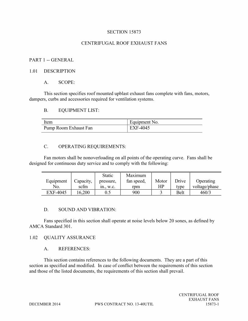
CENTRIFUGAL ROOF
EXHAUST FANS
DECEMBER 2014 PWS CONTRACT NO. 13-40UTIL 15873-1
SECTION 15873
CENTRIFUGAL ROOF EXHAUST FANS
PART 1 -- GENERAL
1.01 DESCRIPTION
A. SCOPE:
This section specifies roof mounted upblast exhaust fans complete with fans, motors,
dampers, curbs and accessories required for ventilation systems.
B. EQUIPMENT LIST:
Item Equipment No.
Pump Room Exhaust Fan EXF-4045
C. OPERATING REQUIREMENTS:
Fan motors shall be nonoverloading on all points of the operating curve. Fans shall be
designed for continuous duty service and to comply with the following:
Equipment
No.
Capacity,
scfm
Static
pressure,
in., w.c.
Maximum
fan speed,
rpm
Motor
HP
Drive
type
Operating
voltage/phase
EXF-4045 16,200 0.5 900 3 Belt 460/3
D. SOUND AND VIBRATION:
Fans specified in this section shall operate at noise levels below 20 sones, as defined by
AMCA Standard 301.
1.02 QUALITY ASSURANCE
A. REFERENCES:
This section contains references to the following documents. They are a part of this
section as specified and modified. In case of conflict between the requirements of this section
and those of the listed documents, the requirements of this section shall prevail.

CENTRIFUGAL ROOF
EXHAUST FANS
15873-2 PWS CONTRACT NO. 13-40UTIL DECEMBER 2014
Unless otherwise specified, references to documents shall mean the documents in effect
at the time of Notice Inviting Bids. If referenced documents have been discontinued by the
issuing organization, references to those documents shall mean the replacement documents
issued or otherwise identified by that organization or, if there are no replacement documents, the
last version of the document before it was discontinued. Where document dates are given in the
following listing, references to those documents shall mean the specific document version
associated with that date, whether or not the document has been superseded by a version with a
later date, discontinued or replaced.
Reference Title
ANSI / ABMA 9 Loading Ratings and Fatigue Life for Ball
Bearings
ANSI / ABMA 11 Load Ratings and Fatigue Life for Roller
Bearings
AMCA 211 Certified Ratings Program – Product Rating
Manual for Fan Air Performance
AMCA 301 Methods for Calculating Fan Sound Ratings from
Laboratory Test Data
B. CERTIFICATION:
Fans shall bear the AMCA rating seal.
1.03 SUBMITTALS
The following information shall be provided in accordance with the requirements of
Section 01300:
1. A copy of this specification section, with addendum updates included, and
all referenced and applicable sections, with addendum updates included,
with each paragraph check-marked to indicate specification compliance or
marked to indicate requested deviations from specification requirements.
Check marks (�) shall denote full compliance with a paragraph as a
whole. If deviations from the specifications are indicated, and therefore
requested by the Contractor, each deviation shall be underlined and
denoted by a number in the margin to the right of the identified paragraph,
referenced to a detailed written explanation of the reasons for requesting
the deviation. The Engineer shall be the final authority for determining
acceptability of requested deviations. The remaining portions of the
paragraph not underlined will signify compliance on the part of the
Contractor with the specifications. Failure to include a copy of the
marked-up specification sections, along with justification(s) for any
requested deviations to the specification requirements, with the submittal
shall be sufficient cause for rejection of the entire submittal with no
further consideration.

CENTRIFUGAL ROOF
EXHAUST FANS
DECEMBER 2014 PWS CONTRACT NO. 13-40UTIL 15873-3
2. A copy of the contract document control diagrams and process and
instrumentation diagrams relating to the submitted equipment, with
addendum updates that apply to the equipment in this section, marked to
show specific changes necessary for the equipment proposed in the
submittal. If no changes are required, the drawing or drawings shall be
marked "no changes required". Failure to include copies of the relevant
drawings with the submittal shall be cause for rejection of the entire
submittal with no further review.
3. Fan performance curves for the specified operating conditions.
4. Motor data form 11060-A as required in Section 11060.
1.04 ENVIRONMENTAL CONDITIONS
Environmental conditions are as specified in Section 01800.
PART 2 -- PRODUCTS
2.01 ACCEPTABLE PRODUCTS
Fans shall be weatherproof, curb mounted, low profile, centrifugal upblast exhaust fans
manufactured by Hartzell, Aerovent, Greenheck, Loren Cook, Penn, or equal, modified to
provide the specified features and to meet the specified operating conditions.
2.02 MATERIALS
Component Material
Hood Aluminum
Fan wheel Aluminum
Fan wheel shaft Stainless steel
Fan housing Spun aluminum
Fasteners Stainless steel
Curb Aluminum
2.03 EQUIPMENT
A. FAN:
Fan housing shall be designed to provide easy access to the motor and fan unit. The fan
inlet shall be provided with a venturi throat that is overlapped by the fan wheel.

CENTRIFUGAL ROOF
EXHAUST FANS
15873-4 PWS CONTRACT NO. 13-40UTIL DECEMBER 2014
The fan wheel shall have forward curved, backward inclined or airfoil blades as provided
standard by the manufacturer for the specified conditions. The wheel shall be statically and
dynamically balanced at the factory. The fan wheel shaft, on belt-driven fans, shall be mounted
in a heavy duty, permanently sealed, permanently lubricated, ball bearing pillow block. Bearings
shall be rated for a minimum ABMA L-10 bearing life of 100,000 hours.
The entire drive assembly, as a unit, shall be removable through the support structure
without dismantling the fan housing. Belt-driven fans shall be furnished with adjustable pitch
sheaves and adjustable motor bases suitable for a plus or minus 5 percent adjustment in operating
speed. The V-belt drive shall be as specified in paragraph 11000-2.03.
B. MOTOR:
Motors shall operate at 1750 rpm and shall be Type 2 as specified in Section 11060.
Motors shall be mounted on vibration isolators and shall be sealed from the exhaust air stream.
Each fan housing shall contain a weatherproof motor starter with watertight conduit
penetration.
C. DAMPER:
Each fan shall be provided with spring loaded barometric type, aluminum backdraft
dampers at the fan inlet.
D. CURB:
Each fan shall be provided with a prefabricated mounting curb. The outer shell of the
curb shall be formed with an integral cant strip and mounting flange. The corners shall be
mitered and welded continuously to form a one-piece leakproof shell. The bottom of the curb
shall have a baseplate which encloses the lower edge of the roof insulation. A damper holding
tray shall be provided. Wooden nailing strips shall be bolted to the top of the curb shell to
provide means for easily attaching the flashing material to the curb.
E. ACCESSORIES:
All fans shall be provided with aluminum bird screens.
2.04 SPARE PARTS
One set of V-belts shall be provided for each belt-driven fan.

CENTRIFUGAL ROOF
EXHAUST FANS
DECEMBER 2014 PWS CONTRACT NO. 13-40UTIL 15873-5
2.05 PRODUCT DATA
The following information shall be provided in accordance with Section 1300 and with
all other pertinent articles of the General Conditions:
1. Bearing ratings for the fan and motor at operating conditions.
2. Certification that the units have been tested and rated in accordance with
the applicable AMCA Standard Test Code and Certified Ratings Program.
3. Applicable operating and maintenance data in accordance with Section
01730.
PART 3 -- EXECUTION
3.01 INSTALLATION
Each fan shall be installed as specified and in accordance with the manufacturer's
recommendations.
3.02 FIELD TESTING
Each fan shall be completely field tested in accordance with Sections 01660 and 15990 to
guarantee compliance with the specifications.
** END OF SECTION **

CENTRIFUGAL ROOF
EXHAUST FANS
15873-6 PWS CONTRACT NO. 13-40UTIL DECEMBER 2014
THIS PAGE INTENTIONALLY LEFT BLANK

DISPOSABLE AIR FILTERS
DECEMBER 2014 PWS CONTRACT NO. 13-40UTIL 15887-1
SECTION 15887
DISPOSABLE AIR FILTERS
PART 1 -- GENERAL
1.01 DESCRIPTION
A. SCOPE:
This section specifies replaceable cartridge type filters for ventilation and process
airstreams. The location of the work is a wastewater lift station facility in Carlsbad, California.
B. EQUIPMENT LIST:
The following is a list of equipment requiring disposable air filters:
Schedule B
Equipment No. Item
ACU-2093 MCC/Electrical Room Air Conditioning Unit
C. OPERATING REQUIREMENTS:
Average filter efficiencies shall be 25 to 30 percent and minimum average filter
arrestance shall be 90 percent, as defined by ASHRAE Standard 52 for face velocities up to 600
feet per minute. Initial resistance to airflow shall not exceed 0.30-inch water column at a face
velocity of 600 feet per minute.
1.02 QUALITY ASSURANCE
A. FACTORY TESTS:
A representative filter of each size, model, and manufacturer provided shall be tested in
accordance with ASHRAE Standard 52. All tests shall be witnessed by an independent certified
testing laboratory approved by ASHRAE. Certified copies of all test data shall be provided.
B. REFERENCES:
This section contains references to the following documents. They are a part of this
section as specified and modified. Where a referenced document contains references to other
standards, those documents are included as references under this section as if referenced directly.
In the event of conflict between the requirements of this section and those of the listed
documents, the requirements of this section shall prevail.

DISPOSABLE AIR FILTERS
15887-2 PWS CONTRACT NO. 13-40UTIL DECEMBER 2014
Unless otherwise specified, references to documents shall mean the documents in effect
at the time of Advertisement for Bids or Invitation to Bid (or on the effective date of the
Agreement if there were no Bids). If referenced documents have been discontinued by the
issuing organization, references to those documents shall mean the replacement documents
issued or otherwise identified by that organization or, if there are no replacement documents, the
last version of the document before it was discontinued. Where document dates are given in the
following listing, references to those documents shall mean the specific document version
associated with that date, regardless of whether the document has been superseded by a version
with a later date, discontinued or replaced.
Reference Title
ANSI / ASHRAE 52.2 Method of Testing General Ventilation Air-Cleaning
Devices for Removal Efficiency by Particle Size
ASTM F1040 Filter Units, Air Conditioning: Viscous-Impingement
and Dry Types, Replaceable
UL 900 Air Filter Units
C. CERTIFICATION:
All filters shall meet the fire-resistance requirements of UL 900, Class 2. All filters shall
bear either the UL label or a certified test report from a recognized independent testing
laboratory, attesting to compliance with UL 900.
PART 2 -- PRODUCTS
2.01 ACCEPTABLE PRODUCTS
Filters shall be American Air Filter, Eco-Air, Farr, or equal, modified to provide the
specified features and performance.
2.02 MATERIALS
Component Material
Filter media Cotton/synthetic blend fabric
Media support grid Steel or aluminum
Filter frame Beverage board
Holding frame Galvanized steel
Cabinet assembly housing Galvanized steel
Mounting tracks Aluminum

DISPOSABLE AIR FILTERS
DECEMBER 2014 PWS CONTRACT NO. 13-40UTIL 15887-3
2.03 EQUIPMENT FEATURES
Filters shall have total cross-sectional surface areas as specified. Filters shall be either
single units or composites comprised of standard 24-inch by 24-inch or 24-inch by 12-inch units.
Filters shall be the pleated media, disposable type, with materials and construction
conforming to ASTM F1040, Type 1. Filter media shall be a high-loft, nonwoven, reinforced
fabric with a minimum thickness of 0.15 inch. The minimum effective filter media for 4-inch
thick filters shall be 7.0 square feet per square foot of filter face area. The minimum effective
filter media for 2-inch thick filters shall be 4.4 square feet per square foot of filter face area. The
filter media shall be bonded to and supported by a welded wire grid located on the leaving air
side of the filter. The media support grid shall have a minimum effective open area of 95
percent. The filter frame shall be rigid, high wet-strength beverage board, with diagonal support
members bonded to the air entering and air leaving sides of the filter media pleats. The inside
periphery of the frame shall be bonded to the filter media and support grid to eliminate the
possibility of air bypass.
2.04 AUXILIARY DEVICES
A. AIR FILTER GAGE:
One air filter gage for each filter or bank of filters shall be provided for measuring the
resistance to airflow through the filter. The gage shall be of the inclined tube, differential
manometer type with over-pressure safety traps to prevent loss of gage fluid. The gage shall be
constructed of solid acrylic plastic with a built-in level vial and adjustable mirror-polished scale.
The scale shall range from 0.10-inch up to 1.0-inch water column. Each gage shall be provided
complete with tubing, two static pressure reading pitot tubes, and mounting hardware. Air filter
gage shall be Dwyer Instruments 250 series, or equal.
B. HOLDING FRAME ASSEMBLY:
Individual holding frames, which can be riveted or bolted together to form a filter bank or
module of the required size, shall be provided for filter enclosures where specified. Holding
frames shall be 16-gage, rectangular units of welded construction and sized to accommodate the
filters specified. Each holding frame shall be formed with an integral sealing flange along all
four sides to provide a mating surface for the front of the filter unit. A sealing gasket attached to
the holding frame sealing flange shall be provided to assure an airtight seal between holding
frame and filter. Each filter shall be pressure clamped to a holding frame with removable
fasteners in such a manner that the filter can be removed and replaced without disturbing the
adjoining filters and frames.
C. SIDE-ACCESS CABINET ASSEMBLY:
Side-access cabinet type enclosures shall be provided for in-line filter installations in
ductwork where specified. Each assembly shall consist of the housing, access doors, filter
mounting tracks, and mechanism for securing and sealing the filter elements. The entire

DISPOSABLE AIR FILTERS
15887-4 PWS CONTRACT NO. 13-40UTIL DECEMBER 2014
assembly shall be factory fabricated and assembled and shall be sized to accommodate the filters
specified. The housing shall be 16-gage, welded construction, and shall be reinforced with
bracing and equipped with flanges for ease of installation into the ductwork. The cabinet
housing shall be equipped with two 16-gage access doors to facilitate removal and replacement
of filters from either side of the unit. The periphery of each door shall be gasketed and provided
with latches for airtight sealing.
2.05 PRODUCT DATA
The following product data shall be provided in accordance with Section 01300:
1. Catalog data and dimensional drawings.
2. Certified copies of factory test results as specified in paragraph 15887-
1.02 A.
3. Certification of compliance with UL 900 as specified in paragraph 15887-
1.02 C.
PART 3 -- EXECUTION
Each filter shall be installed as specified and in accordance with the manufacturer's
recommendations. The perimeter of each filter holding frame, in a holding frame assembly, shall
be caulked to provide an airtight seal between frames. The manufacturer's minimum
recommended clearances for filter removal shall be provided at all filter banks, cabinets, and
equipment containing disposable filters.
** END OF SECTION **

SHEET METAL DUCTWORK
DECEMBER 2014 PWS CONTRACT NO. 13-40UTIL 15891-1
SECTION 15891
SHEET METAL DUCTWORK
PART 1 -- GENERAL
1.01 DESCRIPTION
A. SCOPE:
This section specifies plenums, sheet metal housings, ductwork, equipment connections,
reinforcing and other devices required to make the air distribution systems in non-process areas
complete and operational.
B. TYPE:
Ductwork and appurtenances shall be designed and fabricated specifically for the
applications described under the conditions specified.
C. DESIGN CRITERIA AND CONSIDERATIONS:
1. GENERAL: Unless otherwise specified, sheet metal gage, reinforcing,
hanger and support systems, ductwork joint types and other basic design construction details
shall be in accordance with the Sheet Metal and Air Conditioning Contractors National
Association (SMACNA) HVAC Duct Construction Standards unless otherwise specified.
Ductwork shall be fabricated to the configurations and dimensions specified. Dimensions
specified indicate net free area; dimensions shall be increased by the thickness of the lining
where internal lining is required.
2. LOW PRESSURE DUCTWORK: Low pressure ductwork shall convey
air with a velocity less than 2000 fpm and maximum static pressure of 2 inches of water column.
Low-pressure ductwork shall conform to 2-inch w.c. pressure class.
3. MEDIUM PRESSURE DUCTWORK: Medium pressure ductwork,
where specified, shall convey air with a velocity greater than 2000 fpm and a maximum static
pressure of 6 inches of water column. Medium pressure ductwork shall conform to 6-inch w.c.
pressure class.
4. SYSTEM LEAKAGE: All joints shall be sealed as required to limit total
system leakage to a maximum of 1 percent of the specified equipment airflows.
5. CHANGE IN DUCT SIZE: Change in duct size shall be made by a
uniformly tapering section. The change in direction of the tapering section shall not be more
than 1 inch in 5 inches of run, unless otherwise specified.

SHEET METAL DUCTWORK
15891-2 PWS CONTRACT NO. 13-40UTIL DECEMBER 2014
6. BENDS IN DUCT: With the exception of mitered bends, all bends in
ducts shall have inside radii equal to the duct width or diameter. Double wall turning vanes shall
be provided at all 90-degree mitered bends.
7. DUCT SLEEVES: Whenever ducts extend through concrete or masonry
walls, floors or ceilings, they shall be provided with a sleeve as specified in paragraph
15891-2.04. Concrete inserts shall be provided before pour to support all ductwork under this
section.
8. DUCT OPENINGS: Access doors or hand holes shall be provided in
ducts at locations to reach modulating dampers, fusible links, controllers and any other moveable
devices in the ducts. The opening shall be 1 inch less duct size or of adequate size to reach in
and maintain these devices. Two-inch diameter nipples with threaded caps shall be welded to the
duct where specified or directed by the engineer for balancing the system.
9. VIBRATION ISOLATION FLEXIBLE CONNECTIONS: Flexible
connections shall be provided at duct connections to motor-driven air handling equipment and
other locations specified. Flexible connections shall be UL approved and provided with the
necessary angle, straps, bolts, clips, or other fasteners to secure the flexible material to the
equipment and ducts. Flexible connections exposed to the weather shall be provided with
approved sheet metal or Hypalon weather covers.
10. INSULATION: (Not Used)
1.02 QUALITY ASSURANCE
A. REFERENCES:
This section contains references to the following documents. They are a part of this
section as specified and modified. Where a referenced document contains references to other
standards, those documents are included as references under this section as if referenced directly.
In the event of conflict between the requirements of this section and those of the listed
documents, the requirements of this section shall prevail.
Unless otherwise specified, references to documents shall mean the documents in effect
at the time of Advertisement for Bids or Invitation to Bid (or on the effective date of the
Agreement if there were no Bids). If referenced documents have been discontinued by the
issuing organization, references to those documents shall mean the replacement documents
issued or otherwise identified by that organization or, if there are no replacement documents, the
last version of the document before it was discontinued. Where document dates are given in the
following listing, references to those documents shall mean the specific document version
associated with that date, regardless of whether the document has been superseded by a version
with a later date, discontinued or replaced.

SHEET METAL DUCTWORK
DECEMBER 2014 PWS CONTRACT NO. 13-40UTIL 15891-3
Reference Title
ASHRAE CH 1 Handbook - Equipment Volume, Duct Construction
ASHRAE CH 33 Handbook - Fundamentals Volume, Duct Design
ASTM A653/A653M Steel Sheet, Zinc-Coated (Galvanized) or Zinc-Iron
Alloy-Coated (Galvannealed) by the Hot-Dip Process
ASTM A924/A924M General Requirements for Steel Sheet, Metallic-Coated
by the Hot-Dip Process
ASTM B209 Aluminum and Aluminum Alloy Sheet and Plate
ASTM B211 Aluminum and Aluminum Alloy Bar, Rod, and Wire
ASTM B308/B308M Aluminum - Alloy 6061-T6 Standard Structural Profiles
NFPA 90A Standard for the Installation of Air Conditioning and
Ventilating Systems
SMACNA HVAC Duct Construction Standards Metal and Flexible
IMC International Mechanical Code
UL 181 Factory-made Air Ducts and Connectors
CEC California Energy Commission, Building Energy
Efficiency Standards
B. REQUIREMENTS OF REGULATORY AGENCIES:
Ductwork construction, installation, and air system performance shall comply with
California Energy Commission, IMC, ASHRAE, and SMACNA Duct Construction Standards.
1.03 SUBMITTALS
The following information shall be provided in accordance with Section 01300:
1. A copy of this specification section, with addendum updates included, and
all referenced and applicable sections, with addendum updates included,
with each paragraph check-marked to indicate specification compliance or
marked to indicate requested deviations from specification requirements.
Check marks (�) shall denote full compliance with a paragraph as a
whole. If deviations from the specifications are indicated, and therefore
requested by the Contractor, each deviation shall be underlined and
denoted by a number in the margin to the right of the identified paragraph,
referenced to a detailed written explanation of the reasons for requesting
the deviation. The Construction Manager shall be the final authority for
determining acceptability of requested deviations. The remaining portions
of the paragraph not underlined will signify compliance on the part of the

SHEET METAL DUCTWORK
15891-4 PWS CONTRACT NO. 13-40UTIL DECEMBER 2014
Contractor with the specifications. Failure to include a copy of the
marked-up specification sections, along with justification(s) for any
requested deviations to the specification requirements, with the submittal
shall be sufficient cause for rejection of the entire submittal with no
further consideration.
2. An 8-1/2-inch by 11-inch manual with detail sheets or catalog data of
flexible duct connectors, duct sleeves, duct access doors, turning vanes,
volume dampers, supports, hangers, etc.
PART 2 -- PRODUCTS
2.01 GENERAL
The Contractor shall provide all ductwork, plenums, and all auxiliary work and products
of any kind necessary to make the HVAC systems complete and ready for operation. Ductwork
shall comply with the following restrictions and conditions:
1. Ductmate or ELGEN systems shall be used as an option by the Contractor
for low and medium pressure systems. Follow manufacturing guidelines
for sheet gauge, intermediate reinforcement size and spacing.
2. Pittsburgh Lock will be used on Longitudinal Seams. Snap lock seams
shall not be permitted.
3. Where space conditions permit, full radius turns shall be used at offsets.
4. Turning vanes shall be provided where tees, bends, and elbows are not
1-1/2 times the width at centerline and in all rectangular elbows.
5. Ductwork elbows, takeoffs, and fittings shall be in accordance with the
SMACNA and ASHRAE standards for the pressure class and conditions
specified.
6. Visible duct deflection, loss of shape, or unwarranted noise or vibration
resulting from faulty or inadequate support, reinforcing, metal gage,
fabrication, or joint spacing shall be corrected at no expense to the Owner.

SHEET METAL DUCTWORK
DECEMBER 2014 PWS CONTRACT NO. 13-40UTIL 15891-5
2.02 MATERIALS
A. LOW AND MEDIUM PRESSURE SYSTEMS:
Component Material
Duct Aluminum, alloy 3003-H14, conforming to ASTM
B209 and ASTM B211
Duct sleeve Aluminum, alloy 3003-H14, conforming to ASTM
B209 and ASTM B211
Flexible duct connector Noncombustible, weather and ozone resistant, abrasion-
proof nylon/polyester base fabric with a vinyl coating or
woven fiberglass fabric with coating weighing not less
than 22 ounces per square yard. Maximum flame spread
rating of 25, smoke rating of 50 for all materials
including connecting tape, etc.
Turning vanes Aluminum to match duct material
Hangers and supports, rivets
and bolts, reinforcing
Aluminum, alloy 6061-T6 conforming to ASTM B308
to match duct material.
2.03 JOINTS AND REINFORCING
Transverse stiffeners and joints shall be appropriately spaced to maintain duct cross-
section integrity in accordance with the pressure class specified and at the prevailing operating
velocities. After joints are crimped, they shall be further secured by bottom punching or riveting.
All ducts shall be reinforced by beading. All plenums and casings shall be similarly beaded and
further reinforced with 1-inch x 1-inch x 1/8-inch angles running diagonally between joints,
riveted to the casings.
Low pressure ductwork shall have TDF flanged joints. Medium pressure ductwork shall
have flanged or welded joints. Joints shall not interfere with airflow in the ducts. Exterior ducts
shall be stiffened, braced, and supported in a manner designed to maintain duct integrity and
cross-section under wind and snow loads specified in the appropriate codes or standards as
specified in the California Building Code. Interior ducts shall be suitably braced and stiffened at
floor and roof penetrations as well as over their unsupported length in a manner designed to
maintain duct integrity and limit vibration and noise in accordance with recognized standards of
the industry.
Ducts over 17 inches in largest dimension shall be beaded on all four sides. In ducts over
72 inches at each transverse joint 3/8-inch stay rods shall be installed. Spacing between rods or
rods on side of duct shall not exceed 48 inches.

SHEET METAL DUCTWORK
15891-6 PWS CONTRACT NO. 13-40UTIL DECEMBER 2014
2.04 DUCT SLEEVES
Sleeve flanges shall not be less than 4 inches wide and shall be installed tight against
each side of the barrier. Sleeves shall be 2 inches larger than the duct or external duct insulation.
The space between the duct (or insulation) and the sleeve shall be packed with fiberglass or
material of original wall. Duct flanges not less than 4 inches wide shall be installed tight against
the wall on each side and fastened to the duct sleeves.
2.05 HANGERS AND SUPPORTS
A. GENERAL:
Duct support spacing shall be in accordance with the SMACNA standards for the
pressure class and conditions specified and prevailing in the system. Supports shall be spaced to
prevent visible duct deflection and loss of system integrity. Aluminum ductwork shall be
constructed with strength and dimensional stability comparable to conventional steel duct. In the
absence of other criteria, aluminum sheet and reinforcing shall have a moment of inertia three
times greater than that recommended for steel ductwork. Supports shall be designed in
accordance with California Building Code 2009 for seismic zone in Carlsbad, CA.
B. CONCEALED CEILING SPACES:
Rectangular ductwork shall be supported with channel strut, or metal strap hanger
screwed to the sides and bottom of duct; one strap each side with minimum of two screws in side
and one in bottom of each strap.
C. EXPOSED AREAS:
Rectangular ductwork shall be supported with shelf angle trapeze hanger or unistrut/
channel strut with rods or angles by welding or bolting. Sway bracing shall be provided,
minimum of one at right angle to each duct run.
Round ductwork shall be supported with two half round bands with rods bolted to the
bands. Sway bracing shall be provided, minimum of one at right angle to each duct run.
2.06 ACCESS DOORS
The doors shall be rigid and shall be provided with airtight gaskets and shall not vibrate
or cause noise under service. Doors in insulated ducts shall be the insulated type. Doors shall be
continuous hinged type with cam latch on outside.
Plenum access doors shall be 24 inches by 66 inches or as specified.

SHEET METAL DUCTWORK
DECEMBER 2014 PWS CONTRACT NO. 13-40UTIL 15891-7
2.07 FLEXIBLE CONNECTIONS
Flexible connection joints shall be airtight and have a minimum allowance of 1-inch
slack all around. Flexible connections shall be designed to be removed from the line and be
reinstalled without disassembling adjacent ductwork.
Connections shall be installed with a minimum 4-inch clearance between metal parts on
fan connections, equipment connections, and our distribution devices.
2.08 TURNING VANES
Turning vanes shall be 2-inch blades for ducts up to 18 inches in either dimension and
shall be 4-1/2-inch blades for larger ducts. All turning vane assemblies shall be finished with
an air-dried phenolic corrosion resistant coating prior to installation. All turning vanes shall be
constructed of double thickness vanes.
2.09 DAMPERS
Manually operated, opposed blade or single blade, quadrant-type balancing dampers shall
be provided in each branch duct take-off after leaving the main duct on low pressure systems.
Balancing dampers shall be provided on medium pressure systems where specified. Splitter
dampers shall be provided only where specified.
Single-blade dampers shall be constructed for ducts 9-1/2 inches by 30 inches and
smaller. Opposed blade dampers shall be constructed with a maximum blade size of 12 inches
by 72 inches.
2.10 DUCTWORK COATING
Exposed uninsulated or internally insulated ductwork shall be coated on all external
surfaces in accordance with Section 09900 except in mechanical rooms.
PART 3 -- EXECUTION
3.01 INSTALLATION
Ductwork shall be installed in accordance with SMACNA and NFPA. All ductwork
indicated on the drawings is schematic. Therefore, changes in duct size, duct configuration, and
location may be necessary to conform to field conditions.
Ductwork and accessories shall be installed to provide a system free from buckling,
warping, breathing, and vibration. Ductwork installation shall permit installation of other
required services without piercing, crimping, or reducing duct sizes. Where space conditions
permit, full radius turns shall be used at offsets. The inside of all ducts visible through grilles
and registers shall be painted flat black.

SHEET METAL DUCTWORK
15891-8 PWS CONTRACT NO. 13-40UTIL DECEMBER 2014
All ductwork shall be made airtight. Flanged joints shall be sealed with closed-cell
neoprene gaskets compressed between mating flanges. All other joints and seams shall be sealed
with liquid or mastic type sealants. Taped joints shall not be permitted. All joints shall comply
with the requirements of SMACNA Seal Class A.
All duct fittings shall be fabricated with continuously welded seams and joints.
Should field inspection determine that deviations from these specifications have been
made, the Contractor will be directed to bring the installation into compliance at the Contractor’s
expense.
3.02 TESTS
Tests shall be as specified in Section 15990. Duct test holes with patches in ducts shall
be provided where directed or necessary for testing and balancing purposes.
3.03 DUCTWORK SCHEDULE
Sheet metal ductwork material shall be as follows. Foul air ductwork shall be fiberglass
reinforced plastic (FRP) as specified in Section 13234 or high-density polyethylene (HDPE) as
specified in Section 15065.
Area Material Design criteria
MCC/Electrical Room Aluminum Low-pressure
Lift Station Pump/Motor Room Aluminum Low-pressure
** END OF SECTION **

LOUVERS
DECEMBER 2014 PWS CONTRACT NO. 13-40UTIL 15944-1
SECTION 15944
LOUVERS
PART 1--GENERAL
1.01 DESCRIPTION
A. SCOPE:
This section specifies intake and exhaust air louvers and accessories.
B. PERFORMANCE AND DESIGN REQUIREMENTS:
1. GENERAL: Louver shall be suitable for air supply or discharge service and
shall be sized as specified.
Equipment
No.
Louver dimension, inches
Minimum free
area, %
Maximum
airflow
velocity, fpm Remarks Width Height Depth
NA 120 144 6 45 500 Engine
cooling air
exhaust
1.02 QUALITY ASSURANCE
A. REFERENCE:
This section contains references to the following documents. They are a part of this section
as specified and modified. Where a referenced document contains references to other standards,
those documents are included as references under this section as if referenced directly. In the event
of conflict between the requirements of this section and those of the listed documents, the
requirements of this section shall prevail.
Unless otherwise specified, references to documents shall mean the documents in effect
at the time of Advertisement for Bids or Invitation to Bid (or on the effective date of the
Agreement if there were no Bids). If referenced documents have been discontinued by the
issuing organization, references to those documents shall mean the replacement documents
issued or otherwise identified by that organization or, if there are no replacement documents, the
last version of the document before it was discontinued. Where document dates are given in the
following listing, references to those documents shall mean the specific document version
associated with that date, regardless of whether the document has been superseded by a version
with a later date, discontinued or replaced.

LOUVERS
15944-2 PWS CONTRACT NO. 13-40UTIL DECEMBER 2014
Reference Title
AA DAF 45 Designation System for Aluminum Finishes
ANSI / AMCA 500-L Laboratory Methods of Testing Louvers for Rating
ASTM B221 Aluminum and Aluminum Alloy Extruded Bars, Rods,
Wire, Profiles, and Tubes
ASTM C1071 Fibrous Glass Duct Lining Insulation (Thermal and
Sound Absorbing Material)
B. CERTIFICATION:
Louvers shall bear the AMCA certified ratings seal for both air performance and water
penetration.
PART 2--PRODUCTS
2.01 ACCEPTABLE PRODUCTS
Louvers shall be Airolite, Construction Specialties, Ruskin, or equal, modified to provide
the specified features.
2.02 MATERIALS
Component Material
Blades ASTM B221, 6063-T52 extruded aluminum alloy
Frame ASTM B221, 6063-T52 extruded aluminum alloy
Fasteners Stainless steel or aluminum
Bird screen Aluminum
2.03 EQUIPMENT FEATURES
A. BLADES:
Blades shall be of the fixed, drainable type with interlocking blade braces to provide an
uninterrupted horizontal line. Blades for all louvers shall be minimum 0.081 inch (12 gage) thick.
Slideable interlocked mullions shall have provisions for expansion and contraction.
B. FRAME:
The frame shall be minimum 0.081 inch (12 gage) thick for all louvers. The louver frame
shall be assembled by welding. The head, sill, and jamb shall be one-piece structural members and
shall have an integral calking slot and retaining bead.

LOUVERS
DECEMBER 2014 PWS CONTRACT NO. 13-40UTIL 15944-3
C. SCREEN:
The louver shall be furnished with a removable bird screen constructed of 1/2-inch mesh,
16-gage (0.063 inch) wire and secured within a 10-gage extruded aluminum frame. The screen
shall be mounted on the interior louver face but independent of the louver.
D. FINISH:
Unless otherwise specified, all louvers shall receive a 215-R1, Aluminum Association
Code AA-C22A41, clear anodized finish after assembly. Minimum coating thickness shall be
0.7 mil.
2.04 PRODUCT DATA
Certified results of pressure drop test data and water penetration data for all louvers shall be
provided in accordance with Section 01300.
PART 3--EXECUTION
3.01 INSTALLATION
The louver shall be aligned, connected, and installed as specified and in accordance with the
manufacturer's recommendations. A bituminous coat shall be applied to all aluminum surfaces in
contact with concrete or masonry.
**END OF SECTION**

LOUVERS
15944-4 PWS CONTRACT NO. 13-40UTIL DECEMBER 2014
THIS PAGE INTENTIONALLY LEFT BLANK

HVAC SYSTEMS TESTING,
ADJUSTING, AND BALANCING
DECEMBER 2014 PWS CONTRACT NO. 13-40UTIL 15990-1
SECTION 15990
HEATING, VENTILATING, AND AIR CONDITIONING SYSTEMS
TESTING, ADJUSTING, AND BALANCING
PART 1--GENERAL
1.01 DESCRIPTION
This section specifies the labor and services necessary to test, adjust, and balance under
actual operating conditions air and hydronic systems design flow rates. Nothing herein shall be
construed as relieving the contractor of his overall responsibility of this portion of the work.
1.02 QUALITY ASSURANCE
A. REFERENCES:
This section contains references to the following documents. They are a part of this section
as specified and modified. Where a referenced document contains references to other standards,
those documents are included as references under this section as if referenced directly. In the event
of conflict between the requirements of this section and those of the listed documents, the
requirements of this section shall prevail.
Unless otherwise specified, references to documents shall mean the documents in effect
at the time of Advertisement for Bids or Invitation to Bid (or on the effective date of the
Agreement if there were no Bids). If referenced documents have been discontinued by the
issuing organization, references to those documents shall mean the replacement documents
issued or otherwise identified by that organization or, if there are no replacement documents, the
last version of the document before it was discontinued. Where document dates are given in the
following listing, references to those documents shall mean the specific document version
associated with that date, regardless of whether the document has been superseded by a version
with a later date, discontinued or replaced.
Reference Title
NEBB National Environmental Balancing Bureau
AABC Associated Air Balance Council
ANSI / ASHRAE 70 Method of Testing the Performance of Air Outlets and Air
Inlets
B. TESTING AGENCY:
The Contractor shall procure the services of an independent air and hydronic balancing and
testing agency, belonging to the Associated Air Balance Council (AABC) or the National
Environmental Balancing Bureau (NEBB), to perform air and hydronic balancing, testing and

HVAC SYSTEMS TESTING,
ADJUSTING, AND BALANCING
15990-2 PWS CONTRACT NO. 13-40UTIL DECEMBER 2014
adjustment of systems. The Contractor shall submit a copy of the National Project Certification
Performance Guaranty, issued to the testing agency by the AABC, as a part of the balancing report
specified in paragraph 15990-2.01 B.
C. CODES AND STANDARDS:
The Contractor shall comply with applicable procedures and standards of the certification
sponsoring association:
1. "National Standards for Field Measurements and Instrumentation, Total
Systems Balance, Air Distribution-Hydronics Systems," AABC.
2. "Procedural Standards for Testing, Adjusting, and Balancing of
Environmental Systems", NEBB.
3. "Method of Testing for Rating the Air Flow Performance of Outlets and
Inlets," ASHRAE.
Calibration and maintenance of instruments and accuracy of measurements shall comply
with the requirements of the standards.
1.03 SPECIAL REQUIREMENTS
Tests and adjustments shall include the complete testing and balancing of all hydronic
systems and heating, ventilating, and air conditioning systems and necessary adjustments to the
heating, air conditioning, and ventilating equipment to accomplish the specified design flow rates.
Should any apparatus, material or work fail to meet the specified requirements in these tests,
the Contractor shall make the necessary corrections and retest the apparatus, material, or work at no
additional cost to the Owner.
1.04 BALANCING
A. GENERAL:
The Contractor shall review plans and specifications prior to testing and balancing the air
and hydronic systems. The contractor shall submit a proposed approach and schedule for approval
prior to the start of testing and balancing work. Characteristics to be tested and adjusted to conform
to the values specified include the following:
1. Total airflow rates delivered by fans, air conditioning units, and air-handling
units.
2. Flow rates at all grilles, registers, diffusers, supply and exhaust and return
ducts.

HVAC SYSTEMS TESTING,
ADJUSTING, AND BALANCING
DECEMBER 2014 PWS CONTRACT NO. 13-40UTIL 15990-3
3. Distribution patterns at air outlets.
4. Total water flow rates at each heating and cooling coil, control valve, and
pump.
5. Capacity and temperature rise or drop across each heating and cooling coil.
6. Operation and modulation of each control valve.
B. AIRFLOW RATE MEASUREMENTS:
Airflow rates shall be obtained by adjustment of the fan speeds, dampers, or registers. All
flow rates shall be measured with supply, return, and exhaust systems operating with heating and
cooling coils wet, with filter bank resistance midway between the design values specified for clean
and dirty filters, with auxiliary systems in operation and with all doors and windows closed.
Flow rates at grilles, registers, branch ductwork and air distribution patterns shall be tested
in strict accordance with ASHRAE Standard-70.
C. WATER FLOW RATE MEASUREMENTS:
Total water flow rates shall be measured at each heating coil, cooling coil, unit heater, heat
recovery coil, control valve and pump. Water flow rates shall be obtained by adjustment of
balancing cocks, valves, and fittings. All flow rates shall be measured with control valves
100 percent open. Pump capacities shall be determined by differential pressure measurement.
Temperature shall be measured across the heat transfer elements in the system.
1.05 SUBMITTALS
The following information shall be provided in accordance with Section 01300:
1. A copy of this specification section, with addendum updates included, and
all referenced and applicable sections, with addendum updates included,
with each paragraph check-marked to indicate specification compliance or
marked to indicate requested deviations from specification requirements.
Check marks (�) shall denote full compliance with a paragraph as a whole.
If deviations from the specifications are indicated, and therefore requested by
the Contractor, each deviation shall be underlined and denoted by a number
in the margin to the right of the identified paragraph, referenced to a detailed
written explanation of the reasons for requesting the deviation. The
Construction Manager shall be the final authority for determining
acceptability of requested deviations. The remaining portions of the
paragraph not underlined will signify compliance on the part of the
Contractor with the specifications. Failure to include a copy of the marked-
up specification sections, along with justification(s) for any requested
deviations to the specification requirements, with the submittal shall be

HVAC SYSTEMS TESTING,
ADJUSTING, AND BALANCING
15990-4 PWS CONTRACT NO. 13-40UTIL DECEMBER 2014
sufficient cause for rejection of the entire submittal with no further
consideration.
2. Sample copy of each of the NEBB or AABC report forms.
3. Proposed approach and schedule of testing and balancing work as specified
in paragraph 15990-1.04 A.
4. A description of each air and hydronic system including equipment to be
balanced.
PART 2--PRODUCTS
2.01 BALANCING REPORT
A. REPORT DATA:
The final certified balancing report shall include the following actual field-verified data:
1. Equipment data
a. Manufacturer and model, size, arrangement, class, location, and
equipment number.
b. Motor horsepower, voltage, phase, and full load amperage.
c. Fan cfm, static pressure, rpm, and operating motor BHP.
d. Pump gpm, discharge pressure, suction pressure, pressure change
across pump, total discharge head, gpm at major equipment and
operating motor BHP.
2. Duct size, supply or exhaust recorded cfm, velocity, pressure measurements,
location of all measurements.
3. Pipe size, recorded gpm, velocity, pressure measurements, balancing valve
size and model, location of all measurements.
4. Terminal units
a. Manufacturer and model, supply or exhaust, location, and
identification number.
b. Recorded and design cfm.

HVAC SYSTEMS TESTING,
ADJUSTING, AND BALANCING
DECEMBER 2014 PWS CONTRACT NO. 13-40UTIL 15990-5
c. Recorded and design noise levels and velocities, where specified.
B. REPORT REQUIREMENTS:
1. Each individual final reporting form must bear the signature of the person
who recorded the data and that of the supervisor of the reporting
organization.
2. One certified organization shall perform the testing and balancing services.
3. All instruments which were used shall be listed and identified including the
last date each was calibrated.
C. FINAL REPORT:
Final report shall be submitted prior to Contractor's request for final inspection. In addition
to providing all specified data and information on applicable reporting forms, report shall include
the following:
1. A schedule for testing and balancing parts of the systems which must be
delayed due to seasonal, climatic, occupancy, or other conditions beyond
control of the Contractor. Delayed work shall be completed as early as the
proper conditions will allow, after consultation with the Construction
Manager.
2. Due to delayed testing, reports shall be submitted after execution of those
services.
3. A total balance report shall include the following components:
a. General Information and Summary
b. Instrument Calibration
c. Air Systems
d. Hydronic Systems
e. Temperature Control Systems
f. Special Systems
g. Sound and Vibration Systems
h. Record drawings with specified and measured flow rates
2.02 CERTIFICATE OF COMPLETION
At completion of testing and balancing, Contractor shall submit a Certificate of Compliance
stating that each apparatus, device, outlet, and system has been tested, adjusted, and balanced so that
it is operating in conformance with manufacturer's recommendations and with the specified
conditions.

HVAC SYSTEMS TESTING,
ADJUSTING, AND BALANCING
15990-6 PWS CONTRACT NO. 13-40UTIL DECEMBER 2014
2.03 PRODUCT DATA
The following information shall be provided in accordance with Section 01300:
1. The balancing report specified in paragraph 15990-2.01.
2. Documentation to confirm compliance with codes and standards.
3. NEBB or AABC certification
PART 3--EXECUTION
3.01 GENERAL
The balancing agency shall conduct the above field tests in the presence of the Construction
Manager.
Following completion of testing and balancing the system shall be left in proper working
order, replacing belt guards, closing access doors, closing doors to electrical switch boxes, and
restoring thermostats to specified settings.
3.02 PERFORMANCE OF WORK
A. AIR SYSTEMS:
1. GENERAL: Testing, adjusting, and balancing shall be performed after the
system installation is complete but prior to acceptance of the project.
2. MEASUREMENTS: The Contractor shall perform the following:
a. Measure and adjust air supply and exhaust units to deliver at least
100 percent of the design air volume at 100 percent cooling.
b. Measure static air pressure conditions on fans, including filter and
coil pressure drops, and total pressure across the fan.
c. Adjust fan speeds and motor drives within drive limitations, for
required air volume. Set a speed to provide air volume farthest
distance from the fan without excess static pressure. Check draw
amps of fans on initial start-up. If running amps exceed nameplate,
shut off motor immediately, notify Construction Manager, and make
necessary drive changes as directed.
d. Evaluate building and room pressure conditions to determine
adequate supply and return air conditions.

HVAC SYSTEMS TESTING,
ADJUSTING, AND BALANCING
DECEMBER 2014 PWS CONTRACT NO. 13-40UTIL 15990-7
Airflow rates shall be measured with supply, return, and exhaust systems operating with
heating and cooling coils wet, with filter bank resistance midway between design values specified
for clean and dirty filters, with auxiliary systems in operation. The deflection pattern of supply
outlets shall be adjusted to ensure uniform air distribution throughout the space served.
Airflow rates supplied, exhausted, or returned shall be within plus or minus 5 percent of the
design values specified.
3. SYSTEMS TO BE BALANCED:
1. MCC/Electrical Room Air Conditioning Unit ACU-2039
2. Lift Station Pump Room Ventilation and Exhaust systems
3. Grinder Vault Ventilation system
4. Foul Air Withdrawal and Biofilter Systems
B. HYDRONIC SYSTEMS: Not Used
3.03 FINAL INSPECTION
Following completion of testing and balancing, but prior to submitting the balancing report,
the Contractor shall recheck, in the presence of the Construction Manager, random selections of
data water and air quantities, air motion, and sound levels recorded in the report. Points and areas
for recheck shall be as selected by the Construction Manager. Measurement and test procedures
shall be as approved for work forming basis of the report.
Selections for recheck will not exceed 25 percent of the total tabulated in the report, except
for special air systems, as described in Section 15891, which may require 100 percent recheck for
safety reasons.
In the event the report is rejected, all systems shall be readjusted and tested, new data
recorded, new reports submitted, and new inspection test made.
Following acceptance of the reports by the Construction Manager, the Contractor shall
permanently mark all damper positions, circuit balancing valves, and balancing valves so that they
can be restored to their correct position if disturbed at any time. If a balancing device is provided
with a memory stop, it shall be set and locked. Devices shall not be marked until after final
inspection.
**END OF SECTION**

HVAC SYSTEMS TESTING,
ADJUSTING, AND BALANCING
15990-8 PWS CONTRACT NO. 13-40UTIL DECEMBER 2014
THIS PAGE INTENTIONALLY LEFT BLANK