Embed Size (px)
Citation preview
Exposition LRT Project Phase 2 02/20/2013PRE-FINAL DESIGN SUBMITTAL
REVISION B
SECTION 14240-DB
HYDRAULIC ELEVATORS
HYDRAULIC ELEVATORS 14240-DB - 1
PART 1 – GENERAL
1.1 DESCRIPTION
A. The Work in this Section consists of furnishing, storing and installing hydraulicheavy duty transit elevator systems as indicated. Hydraulic elevators for thisproject shall conform to the Approved Design Drawings and the requirements ofthis Specification.
1.2 QUALITY CONTROL
A. Comply with General Requirements Section 01460, Project Quality ManagementProgram requirements.
B. Qualifications of Bidders
1. Manufacturer's Qualifications: The design, engineering and manufactureof major elevator components such as machines, motors, motor driveunits, controllers, door operators, safeties, governors, selectors, powerunits, etc. shall be from manufactures that have been in the business forthe last ten years. Equipment proposed must have a history ofsuccessful operation under similar conditions for the last two (2) years.
2. Installer and Maintenance Qualifications: Installer must be a licensed C-11 Elevator Contractor in the State of California. Installer must belicensed as a Certified Competent Elevator Contractor (CCEC) with theState of California.
a. Show evidence of successful experience in complete installationand maintenance of proposed manufacturer's elevator equipmentfor at least two (2) years.
b. Directly employ sufficient competent personnel within 50 miles ofAuthority to handle construction and maintenance duties.
c. Maintain local stock of parts adequate for replacement onpermanent or emergency basis.
d. Respond to trouble calls within 45 minutes.
Exposition LRT Project Phase 2 02/20/2013PRE-FINAL DESIGN SUBMITTAL
REVISION B
HYDRAULIC ELEVATORS 14240-DB - 2
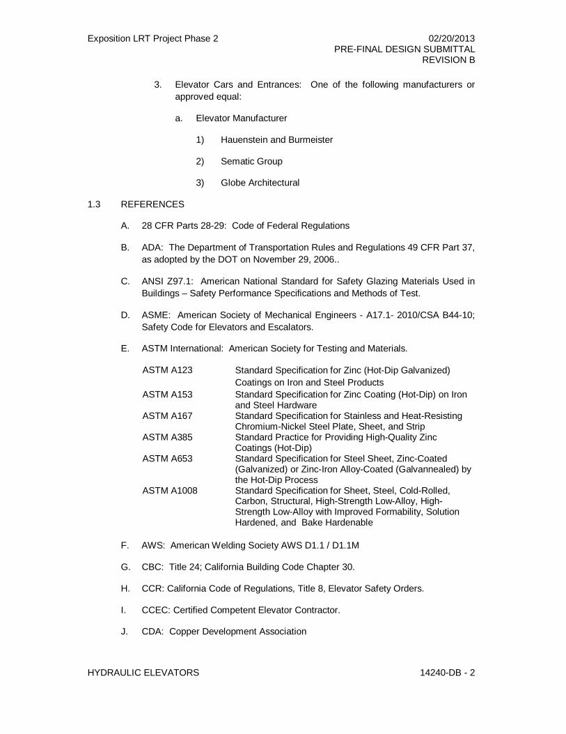
3. Elevator Cars and Entrances: One of the following manufacturers orapproved equal:
a. Elevator Manufacturer
1) Hauenstein and Burmeister
2) Sematic Group
3) Globe Architectural
1.3 REFERENCES
A. 28 CFR Parts 28-29: Code of Federal Regulations
B. ADA: The Department of Transportation Rules and Regulations 49 CFR Part 37,as adopted by the DOT on November 29, 2006..
C. ANSI Z97.1: American National Standard for Safety Glazing Materials Used inBuildings – Safety Performance Specifications and Methods of Test.
D. ASME: American Society of Mechanical Engineers - A17.1- 2010/CSA B44-10;Safety Code for Elevators and Escalators.
E. ASTM International: American Society for Testing and Materials.
ASTM A123 Standard Specification for Zinc (Hot-Dip Galvanized)Coatings on Iron and Steel Products
ASTM A153 Standard Specification for Zinc Coating (Hot-Dip) on Ironand Steel Hardware
ASTM A167 Standard Specification for Stainless and Heat-ResistingChromium-Nickel Steel Plate, Sheet, and Strip
ASTM A385 Standard Practice for Providing High-Quality ZincCoatings (Hot-Dip)
ASTM A653 Standard Specification for Steel Sheet, Zinc-Coated(Galvanized) or Zinc-Iron Alloy-Coated (Galvannealed) bythe Hot-Dip Process
ASTM A1008 Standard Specification for Sheet, Steel, Cold-Rolled,Carbon, Structural, High-Strength Low-Alloy, High-Strength Low-Alloy with Improved Formability, SolutionHardened, and Bake Hardenable
F. AWS: American Welding Society AWS D1.1 / D1.1M
G. CBC: Title 24; California Building Code Chapter 30.
H. CCR: California Code of Regulations, Title 8, Elevator Safety Orders.
I. CCEC: Certified Competent Elevator Contractor.
J. CDA: Copper Development Association
Exposition LRT Project Phase 2 02/20/2013PRE-FINAL DESIGN SUBMITTAL
REVISION B
HYDRAULIC ELEVATORS 14240-DB - 3
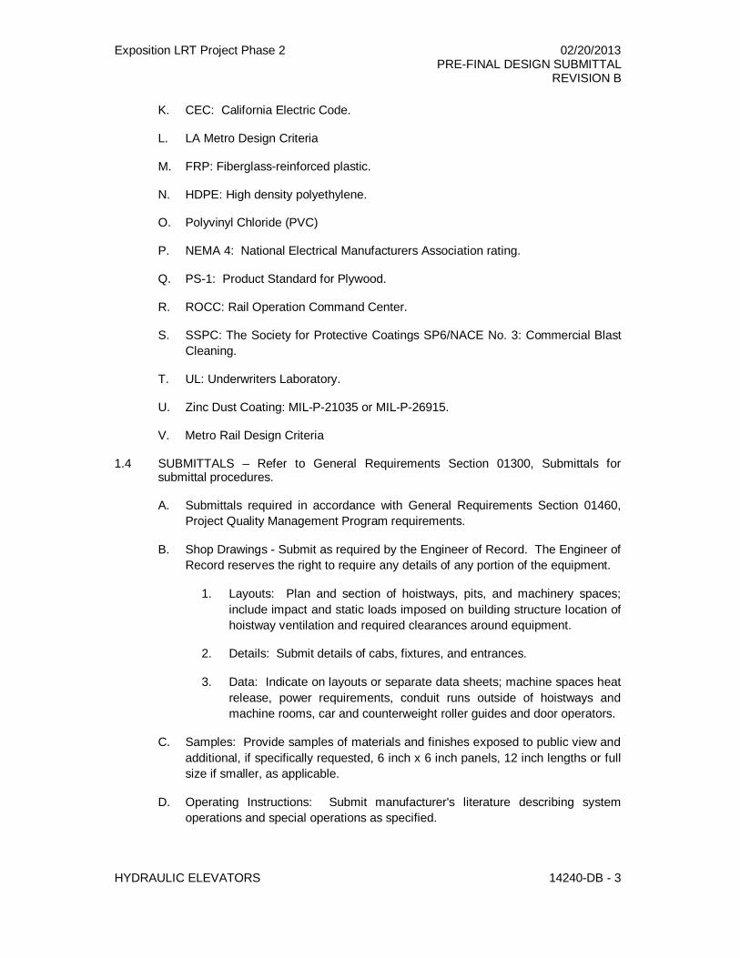
K. CEC: California Electric Code.
L. LA Metro Design Criteria
M. FRP: Fiberglass-reinforced plastic.
N. HDPE: High density polyethylene.
O. Polyvinyl Chloride (PVC)
P. NEMA 4: National Electrical Manufacturers Association rating.
Q. PS-1: Product Standard for Plywood.
R. ROCC: Rail Operation Command Center.
S. SSPC: The Society for Protective Coatings SP6/NACE No. 3: Commercial BlastCleaning.
T. UL: Underwriters Laboratory.
U. Zinc Dust Coating: MIL-P-21035 or MIL-P-26915.
V. Metro Rail Design Criteria
1.4 SUBMITTALS – Refer to General Requirements Section 01300, Submittals forsubmittal procedures.
A. Submittals required in accordance with General Requirements Section 01460,Project Quality Management Program requirements.
B. Shop Drawings - Submit as required by the Engineer of Record. The Engineer ofRecord reserves the right to require any details of any portion of the equipment.
1. Layouts: Plan and section of hoistways, pits, and machinery spaces;include impact and static loads imposed on building structure location ofhoistway ventilation and required clearances around equipment.
2. Details: Submit details of cabs, fixtures, and entrances.
3. Data: Indicate on layouts or separate data sheets; machine spaces heatrelease, power requirements, conduit runs outside of hoistways andmachine rooms, car and counterweight roller guides and door operators.
C. Samples: Provide samples of materials and finishes exposed to public view andadditional, if specifically requested, 6 inch x 6 inch panels, 12 inch lengths or fullsize if smaller, as applicable.
D. Operating Instructions: Submit manufacturer's literature describing systemoperations and special operations as specified.
Exposition LRT Project Phase 2 02/20/2013PRE-FINAL DESIGN SUBMITTAL
REVISION B
HYDRAULIC ELEVATORS 14240-DB - 4
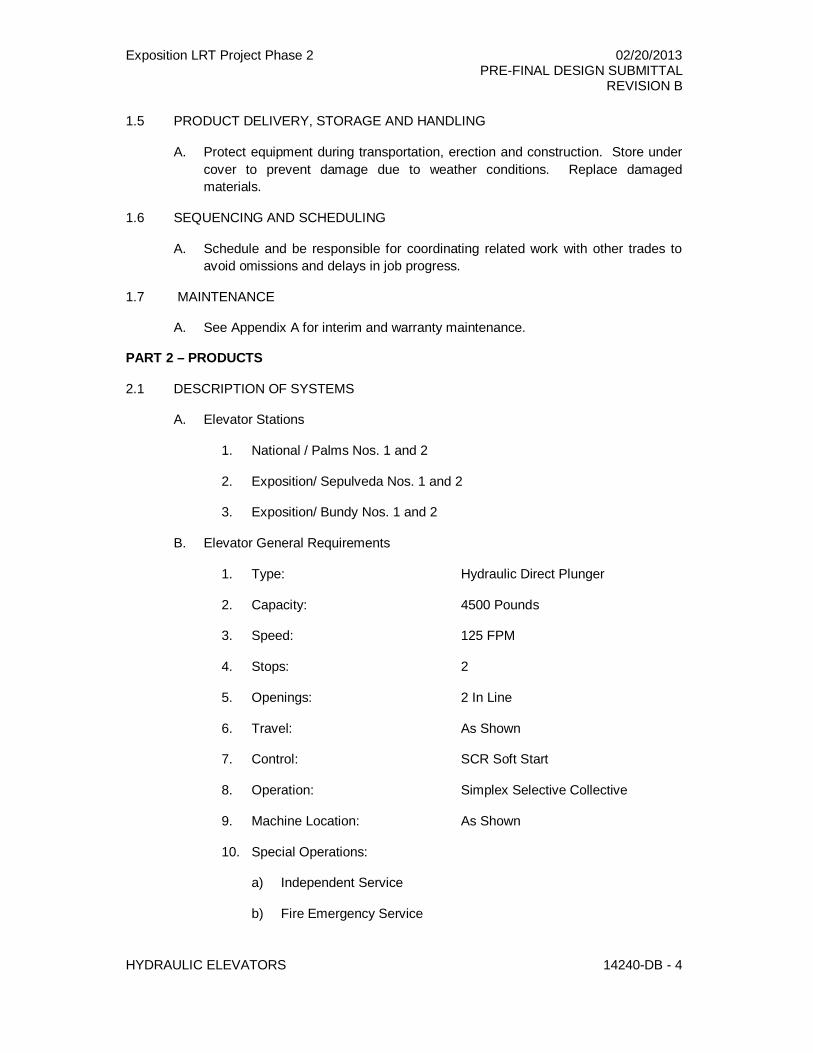
1.5 PRODUCT DELIVERY, STORAGE AND HANDLING
A. Protect equipment during transportation, erection and construction. Store undercover to prevent damage due to weather conditions. Replace damagedmaterials.
1.6 SEQUENCING AND SCHEDULING
A. Schedule and be responsible for coordinating related work with other trades toavoid omissions and delays in job progress.
1.7 MAINTENANCE
A. See Appendix A for interim and warranty maintenance.
PART 2 – PRODUCTS
2.1 DESCRIPTION OF SYSTEMS
A. Elevator Stations
1. National / Palms Nos. 1 and 2
2. Exposition/ Sepulveda Nos. 1 and 2
3. Exposition/ Bundy Nos. 1 and 2
B. Elevator General Requirements
1. Type: Hydraulic Direct Plunger
2. Capacity: 4500 Pounds
3. Speed: 125 FPM
4. Stops: 2
5. Openings: 2 In Line
6. Travel: As Shown
7. Control: SCR Soft Start
8. Operation: Simplex Selective Collective
9. Machine Location: As Shown
10. Special Operations:
a) Independent Service
b) Fire Emergency Service
Exposition LRT Project Phase 2 02/20/2013PRE-FINAL DESIGN SUBMITTAL
REVISION B
HYDRAULIC ELEVATORS 14240-DB - 5
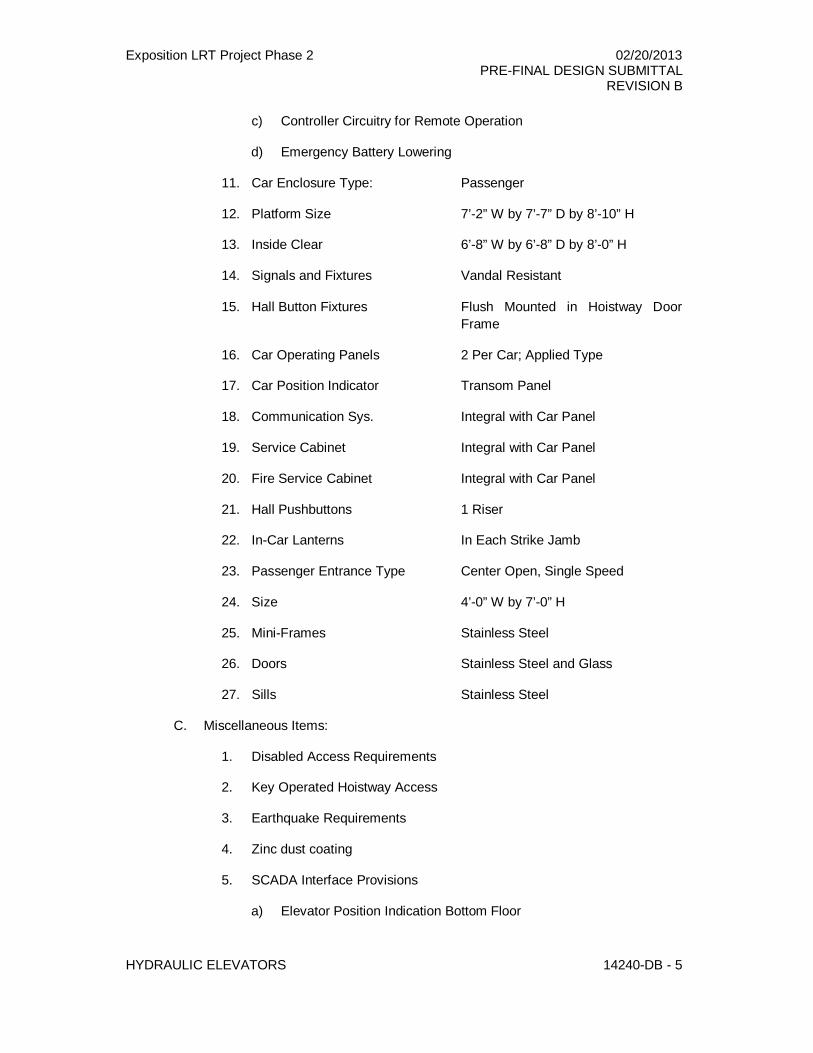
c) Controller Circuitry for Remote Operation
d) Emergency Battery Lowering
11. Car Enclosure Type: Passenger
12. Platform Size 7’-2” W by 7’-7” D by 8’-10” H
13. Inside Clear 6’-8” W by 6’-8” D by 8’-0” H
14. Signals and Fixtures Vandal Resistant
15. Hall Button Fixtures Flush Mounted in Hoistway DoorFrame
16. Car Operating Panels 2 Per Car; Applied Type
17. Car Position Indicator Transom Panel
18. Communication Sys. Integral with Car Panel
19. Service Cabinet Integral with Car Panel
20. Fire Service Cabinet Integral with Car Panel
21. Hall Pushbuttons 1 Riser
22. In-Car Lanterns In Each Strike Jamb
23. Passenger Entrance Type Center Open, Single Speed
24. Size 4’-0” W by 7’-0” H
25. Mini-Frames Stainless Steel
26. Doors Stainless Steel and Glass
27. Sills Stainless Steel
C. Miscellaneous Items:
1. Disabled Access Requirements
2. Key Operated Hoistway Access
3. Earthquake Requirements
4. Zinc dust coating
5. SCADA Interface Provisions
a) Elevator Position Indication Bottom Floor
Exposition LRT Project Phase 2 02/20/2013PRE-FINAL DESIGN SUBMITTAL
REVISION B
HYDRAULIC ELEVATORS 14240-DB - 6
b) Elevator Position Indication Top Floor
c) Elevator Trouble Indication
d) Elevator Call Indication Bottom Floor
e) Elevator Call Indication Top Floor
f) Elevator Lockout Active Indication
g) Elevator Fire Recall Active Indication
h) Elevator Emergency Mode Indication
i) Elevator Remote Call Control for Bottom Floor
j) Elevator Remote Call Control for Top Floor
k) Elevator Lockout Activate and cancel control
l) Elevator One-Trip Control
6. Car Top Air Conditioning Unit
2.2 FINISHES
A. Exposed-to-View Surfaces. Provide as follows unless otherwise indicated in theApproved Design Drawings:
1. Aluminum: Clear anodized finish.
2. Nickel Silver: Satin brushed finish.
3. Sheet Steel:
4. Shop Prime: Degrease clean of foreign substances and apply one coatof corrosion inhibiting primer compatible with finish paint selected.Hoistway items visible to public shall be painted one additional coat ofblack paint.
5. Finish Paint: Factory applied baked enamel or powder coat; color asselected by Engineer and approved by Authority.
6. Stainless Steel: Elevator finish materials shall be #4 brushed finishedstainless steel on all glazed wall surfaces, doors, frames, sills, and trim.Interior stainless steel shall be textured finish Rigidized 5.WL or 6.WL orequivalent.
7. Touch-Up:
8. Prime Surfaces: Use same paint as factory for field touch-up.
Exposition LRT Project Phase 2 02/20/2013PRE-FINAL DESIGN SUBMITTAL
REVISION B
HYDRAULIC ELEVATORS 14240-DB - 7
9. Finish Painted Surfaces: Refinish whole panel with shop prime andfinish paint as specified above
B. Non-Exposed-to-View Surfaces: Degrease and shop paint manufacturer'sstandard corrosion inhibiting primer.
C. Paint and Corrosion Protection: Equipment shall have the following minimumcorrosion protection:
1. Steel parts which are not specified to be galvanized shall be painted with1) a first finish coat of two (2) mil dry film thickness and 2) a secondfinish coat of two (2) mil dry film thickness
D. Installed Environment: All hoistway and car equipment shall be designed for adamp environment. Except for GAL MOVFRW, electrical components in the pit,hoistway, and at each hoistway landing shall be NEMA 4 design. All hoistwayentrance equipment shall be galvanized steel or fabricated from a nonferrousmaterial.
2.3 AUTOMATIC OPERATION
A. General Operation of Individual Elevators
1. Provide a non-proprietary microprocessor-controlled dispatching systemdesigned to monitor all types of traffic and sufficiently flexible so that itcan be modified to accommodate changes in traffic patterns. Includehardware necessary to protect hoist motors, motor drives and dooroperators. Software shall control group and simplex program operations.
2. Pre-Approved Products
3. Provide Motion Control Engineering HMC-1000 SCR or approved equal.
4. The system shall continuously monitor the demand based on real-timecalculations to assign and reassign the elevators to handle the traffic inthe most efficient manner.
5. Fault Diagnostic System: Provide all hardware such as on-board LED,diagnostics, hand-held device, or laptop computer, as is standard withmanufacturer, and supporting software documentation. Diagnosticsystem shall be capable of determining faults most difficult to find.
B. Two-Stop Collective Operation
1. Provide a microprocessor-based control system to perform functions ofelevator motion, car operation dispatching, and door control.
2. Operate elevator from single button landing stations and operatingbuttons in car.

Exposition LRT Project Phase 2 02/20/2013PRE-FINAL DESIGN SUBMITTAL
REVISION B
HYDRAULIC ELEVATORS 14240-DB - 8
3. Landing or car button shall cause car to start and proceed to that floor.Doors shall open automatically when car arrives. When car is travelingaway from a registered landing call, call shall remain registered and carshall respond on next trip.
2.4 SPECIAL OPERATIONS
A. Inspection Operation: Provide key-operated hoistway access device and car topoperating device. Key switches shall be mounted in doorframes with only ferruleexposed at terminal landings.
B. Independent Service: Independent service operation shall be provided so that,by means of a switch located in the car service cabinet, the car can be removedfrom automatic operation and be operated by an attendant. The attendant shallhave full control of the starting, stopping, and direction of car travel. The carshall respond to car buttons only. The hall signals for the car on independentservice shall not operate.
C. Operation Under Fire or Other Emergency Conditions: Provide specialemergency service. Provide Phase 1 recall switch at Street Level Elevator. Keyswitches at Street Level shall be integrated in buttons with engraved instructions.Key shall match existing Metro elevators, per Metro Design Criteria 6.14.7.A.7.c
D. Remote Control: Provide interface to remotely control the elevator from SCADAinterface as follows:
1. Function, which calls out and locks the elevator at top or bottom floor.
2. Function, which releases a bottom or top locked elevator to make onetrip and then recall to the lock state.
3. Remote operations can be overridden by cars on independent and anyspecial emergency service.
4. Provide interface to remotely enter car and hall calls.
E. Emergency Battery Lowering: Provide emergency battery lowering system whichallows unloading of elevator in blackout situations. Under emergency situationsthe elevator will lower to the lowest landing and open the doors to allowpassengers to exit.
2.5 DOOR OPERATION
A. Passenger Type Horizontal Sliding
1. Door Operator: Provide heavy-duty master type operator. Provideclosed-loop door operators, GAL-MOVFRW, MAC DPSS or approvedequal. Provide weather resistant enclosed door operator.
2. Provide door times available as specified in paragraph 2.10, A below.
Exposition LRT Project Phase 2 02/20/2013PRE-FINAL DESIGN SUBMITTAL
REVISION B
HYDRAULIC ELEVATORS 14240-DB - 9
3. Car and hoistway doors shall open and close simultaneously, andsmoothly; door movement shall be cushioned at both limits of travel.Door operation shall not cause cars to move appreciably.
4. Door open times shall be readily and independently adjustable when carstops for a car or hall call. Street Level door hold times shall beadjustable independent of other floors.
5. Hangers and Tracks: Sheave type with two-point suspension. Steelsheaves with flanged groove and resilient sound-absorbing tires.Minimum 2-1/2 inch diameter for hoistway, 3 inch for car. Manufacturer'sheavy-duty tracks and ball or roller bearing with adjustable up thrusts.
B. Door Protection; Passenger Type
1. Electronic Scanning Type
2. Provide a door protective system that does not rely on physical contactwith a person or object to inhibit door movement or initiate door reversal.Provide the waterproof Tritronics EZ edge or approved equal.
3. The system shall be able to detect a 2-inch diameter rod introduced atany position within the door movement and between the height of 2inches and 63 inches above sill level.
4. Detection of intrusion into the protected area shall cause the doors, iffully open, to be held in the open position and, if closing, to reverse tofully open position.
5. If doors are prevented from closing for an adjustable period of 15 to 45seconds or upon activation of Fire Emergency Service, they shallproceed to close at reduced speed and a loud buzzer shall sound. Doorclosing force shall not exceed 2-1/2 ft.-lbs. when door reopening deviceis not in operation.
C. Interlocks: Equip each hoistway door with a tamper-proof interlock, which shallprevent operation of the car until doors are locked in the close position as definedby ASME A17.1. Interlock shall prevent opening of doors at landing from corridorside unless car is at rest at landing, is traveling through leveling zone or hoistwayaccess switch is used. Interlocks shall lock the two door sections together.
2.6 SIGNALS AND OPERATING FIXTURES
A. General: Provide signals and fixtures as shown and specified. Location andarrangement of fixtures shall comply with disabled access requirements.
1. Elevator Buttons: Provide vandal-resistant stainless steel minimum 1inch diameter mechanical buttons, raised 1/8 inch from surroundingsurface with square shoulders and integral illumination. Provide
Exposition LRT Project Phase 2 02/20/2013PRE-FINAL DESIGN SUBMITTAL
REVISION B
HYDRAULIC ELEVATORS 14240-DB - 10
Innovation Industries fixtures or approved equal. Operation of car or hallbutton shall cause button to illuminate. Response of car to car or hallcall shall cause corresponding button to extinguish.
2. Switches: Toggle type typically or key operated where noted onApproved Design Drawings.
3. Faceplates: Provide stainless steel faceplates, 1/8 inch minimumthickness with sharp edges relieved.
4. Fastenings: Provide with flush tamper-proof screws of material andfinish matching faceplates.
5. Cabinets: Provide with pulls, concealed hinges, and doors mountedflush with hairline joints to adjacent surface. All material to be fabricatedfrom stainless steel.
6. Arrangement: Arrangement of fixtures shall generally conform to theApproved Design Drawings. Any deviations shall be subject toEngineer’s approval.
7. Engraving: Of size indicated on Approved Design Drawings; colorbackfill with epoxy paint in contrasting color as selected.
8. Lamps: Miniature LED type.
9. Audible Chimes: Electronic adjustable audible chimes; bell type gongnot acceptable.
10. Provide floor passing signal of the adjustable electronic audible chimetype.
11. Tactile Markings: Provide raised Braille and alpha characters, numerals,or symbols to the left of operating buttons and devices used by thepublic. Indications may be engraved directly on faceplates or on separatecast plates flush and rear mounted with hairline joints and concealedmechanical fasteners. Plates shall be of same size and shape asbuttons. Raised characters shall be white on a black background withBraille designation directly below the character.
12. Provide NEMA 4 signal fixtures and enclosures.
B. Car Operating Panels
1. General: Provide buttons numbered to conform to floors served and thefollowing:
2. Locate top operating button at 48 inches above floor.
Exposition LRT Project Phase 2 02/20/2013PRE-FINAL DESIGN SUBMITTAL
REVISION B
HYDRAULIC ELEVATORS 14240-DB - 11
3. Locate emergency stop and illuminated alarm button in bottom row at 35inches above floor. Wire emergency stop to ring alarm bell.
4. Provide "Door Open", and "Door Close" buttons located aboveemergency stop and alarm of same design as car button.
5. Engrave main panel with capacity, number of passengers, and elevatornumber in 1/4-inch letters. All other signage required by local codesshall be engraved in 1/4-inch letters.
6. Provide fire emergency key switch, controls in locked cabinet per ASMEA17.1, engraved instructions and call cancel button with audible/visualsignals. Key shall match existing Metro elevators, per Metro DesignCriteria 6.14.7.A.7.m
7. Applied Type: Integrate cabinets, buttons and engraving into hingedsingle piece faceplate mounted to front return panel.
C. Car Position Indicators: Provide car position indicators with indicationscorresponding to floor designations with matching direction arrows. Provide amulti-light, vandal-resistant-type indicator with individual jewels and 1-1/2 inchhigh numerals on faceplate above the car door.
D. Service Cabinet: Provide cabinet door with a lock and concealed hinge as anintegral part of car operating panel. Service cabinet shall contain the following:
1. Independent service switch, key operated.
2. Two-speed ventilation switch.
3. Light switch.
4. Inspection switch, key operated.
5. Duplex convenience outlet.
6. Buzzers as required.
7. Constant pressure test switch for emergency car lighting.
E. Car Station shall be provided with a flush glazed window of required size to holdelevator-operating permit.
F. Emergency Telephone (ETEL): Provide a complete system compatible with thefeatures of VPP T2100 Series in compliance with disabled access regulationsconsisting of a combination speaker/microphone, amplifier, and matching carstation pushbutton with telephone symbol to activate system and call-acknowledgement lights. Mount behind a pattern of holes as an integral part ofcar operating panel. Wire to machine room and program to call ROC (RailOperations Control) unless otherwise directed by Engineer. ETEL’s faceplate
Exposition LRT Project Phase 2 02/20/2013PRE-FINAL DESIGN SUBMITTAL
REVISION B
HYDRAULIC ELEVATORS 14240-DB - 12
shall be 30178/208A or approved equal. ETEL shall be provided with a statusline monitor.
G. Hall Button Fixtures: Each NEMA 4 fixture shall contain buttons that light toindicate hall call registration and extinguish when call is answered. Engrave fire-exiting instructions on faceplates. Hall button faceplates shall be surfacemounted. Integrate access and Firefighter’s key switches into same faceplate.
H. Car Lanterns: Dual vandal-resistant car riding lantern mounted at a maximumheight above floor. Lens shall be flush with faceplate. Lantern shall illuminateand chime as doors open. Provide single chime for up direction and doublechime for down direction.
2.7 WIRING
A. General: Provide all necessary wiring with 15% or a minimum of four sparesbetween cars and controllers and to all remote control stations. Furnish shieldedwires in cables for all communications and speakers. Include two additional pairsof shielded spares for each car.
B. Traveling Cables: Use minimum number of traveling cables with flame-retardingand moisture-resisting covers. Include shielded wires and spares as notedabove. Cord thoroughly and protect cables from rubbing against hoistways orcar items. Provide with steel cable core and properly anchored to relieve strainon individual conductors.
C. Work Light and Convenience Outlet: Provide on top of car with wire lamp guard.
D. CCTV: Provide 110 volt duplex outlet on car top for CCTV power supply. Alsoprovide a CCTV video cable to a demarcation point as indicated on theapplicable drawings.
E. Stop Switch: Provide in each pit and on top of car.
F. Alarm Gong: Six-inch size, 110 volt. Provide on top of each car, to be actuatedby corresponding alarm button or emergency stop switch.
G. Auxiliary Disconnect Switches: Provide as required in remote controller rooms orat remote equipment not in view of mainline switches; include all wiring and con-duit. Refer to Section 16050-DB, Electrical Construction, Paragraph 2.13EDisconnecting Devices for special requirements of the Elevator DisconnectSwitch for interfacing with the Fire Alarm Control Panel.
H. Emergency Telephone: Provide (4) shielded 22 gauge pairs of wires from theelevator car to the machine room junction box.
I. Coaxial Circuit or Fiber Optic: Provide for closed circuit television camera inelevators. Run two (2) RG-59U cables from elevator car to machine roomjunction box.
Exposition LRT Project Phase 2 02/20/2013PRE-FINAL DESIGN SUBMITTAL
REVISION B
HYDRAULIC ELEVATORS 14240-DB - 13
J. Provide gutter in machine room for all related interface in the elevator machineroom to tie into controller. All of the SCADA Interface provisions shall be wiredthrough auxiliary relay dry contacts located in the elevator’s control unit. Oncethe elevator SCADA interface relay drawings are available, a Systems-Facilitymeeting will be initiated to confirm all field wiring between the elevator controllerand the Systems Design. All control activations from SCADA will be bymomentary input signals to the elevator controller. All alarm or positionindications from the elevator controller will be from the dry contacts of theauxiliary relays.
2.8 CAR ENCLOSURES
A. General: Fabricate finish work smooth and free from warps, buckles, squeaks,and rattles; joints lightproof. No visible fastenings, except when specificallyapproved by Engineer.
B. Passenger Car
1. Stainless Steel Shell: Fabricate of 14-gauge sheet, tube, and extrusions,stainless steel from floor to canopy. Canopy 12 gauge reinforcedstainless steel.
2. Glass Panels: Provide glass observation panels on side and rear wallsas detailed. Glass shall run from floor to finish ceiling height, withceramic frit as detailed on drawings. Glass panels shall be laminatedsafety glass meeting the requirements of ANSI Z97.1. Installation andmounting shall be in accordance with CCR Title 8 and ASME A17.1.Mullion finish shall match other metal finishes within car enclosure befabricated from stainless steel without exposed fasteners.
3. Exterior Cladding: All surfaces exposed to public view on exterior of carshall be fabricated from minimum 14-gauge stainless steel. Claddingshall extend 2 feet 0 inches below finish car floor and 3 feet 6 inchesabove car canopy and shall have a continuous closure panel on the topand bottom.
4. Emergency Exit: Top of car per ASME A17.1.
5. Car Doors: Fabricate frame from stainless steel each panel sufficientlyreinforced to support glass panels in accordance with ASME A17.1requirements. Provide two guides per panel located one inch from eachend. Provide full-length neoprene astragals.
6. Front Return Panels: Provide fixed type front return panels fabricatedfrom 14 gauge stainless steel.
7. Canopy and Lighting: 12 gauge reinforced stainless steel with recesseddetention type fluorescent light fixtures with protective lens.
Exposition LRT Project Phase 2 02/20/2013PRE-FINAL DESIGN SUBMITTAL
REVISION B
HYDRAULIC ELEVATORS 14240-DB - 14
8. Ventilation: Provide quiet, low voltage fan capable of 400 cfm airmovement, with temperature control and battery operation. Use Man-D-Tech Model EVS-4 or approved equal. Car top air conditioning unit tomaintain temperature within car to less than 90 degrees and provide oneair change per minute. Provide vent slots in base.
9. Handrail: Provide a 1-1/2 inch diameter stainless steel rail on rear andside walls with intermediate horizontal rails as required by Titles 8 & 24,mounted with matching brackets securely attached to car shell.
10. Sills: Provide extruded stainless steel threshold plate. Mount withconcealed mechanical fasteners. Allow for installation of finish flooringby others.
11. Finish Flooring: Concrete pavers in pattern as shown on ApprovedDesign Drawings. Allow 2 inches for setting bed and stone finish flooring,with stainless steel trim. .
C. Emergency Lighting; All Elevators: Provide an emergency car lighting unitmounted on top of car, battery driven and self-rechargeable. Upon outage ofnormal power the unit shall, within 5 seconds, light two lamps as part of normalcar lighting or separate lights mounted above drop ceiling. The unit shall havesufficient capacity to keep the lights in continuous operation for four hours andalso the alarm bell for one hour. Provide a readily accessible means for testingthe unit in service cabinet. Light fixtures mounted in car front returns or operatingpanels are not acceptable.
2.9 HOISTWAY ENTRANCES; PASSENGER TYPE
A. General: Fabricate finish work smooth with flush surfaces and free from warpsand buckles. Provide mini-jamb entrances of stainless steel with steel reinforcingto achieve design intent shown on Approved Design Drawings. Mini-jamb to sitflush with hoistway line and may be attached by shrouding subcontractor. Placemini-jamb before shrouding is begun
B. Struts and Closer Angles: As required for entrance installation and door closermechanism. Hanger headers, minimum 3/16 inch material extending from strutto strut. Note design intent is to eliminate struts.
C. Dust and Hanger Covers: Provide as required of minimum 16-gauge stainlesssteel. Provide hanger cover plates extending full length of door track.
D. Sills: Extruded sills with nonskid surfaces and grooves suitable for guides.Extend strut to strut and mount without exposed screws. Provide all supportangles and levelers for a complete installation. Sill material shall be stainlesssteel.

Exposition LRT Project Phase 2 02/20/2013PRE-FINAL DESIGN SUBMITTAL
REVISION B
HYDRAULIC ELEVATORS 14240-DB - 15
E. Frames: Fabricate from 14-gauge material with side jambs in one continuouspiece from sill to head section. Head and jamb flush, stainless steel finish. Backfill door frames with concrete.
F. Doors: Same as car doors, stainless steel and glass.
G. Tactile Markings: Provide raised Braille and alpha characters, numerals, orsymbols as required by 28 CFR Part 36. Rear mounted flush on each entrancejamb at 60 inches above floor indicating floor designation. Braille plates securedwith adhesive are unacceptable. Material and finish of plates shall have contrast-ing background and mounting means similar to those on car panels.
2.10 HYDRAULIC ELEVATOR EQUIPMENT
A. Design Criteria:
1. Performance:
2. Contract Speed: Maximum twenty percent (20%) speed variation underany loading condition in either direction.
3. Motion Time: From start to stop of elevators motion as measured in bothdirections for a typical one-floor run under any loading condition. Initiatemovement of car within 1.5 second after make-up of hoistway doorinterlock. Typical floor height of 26’-9”.
a. 125 FPM: 18.1 seconds.
4. Door Open Times:
a. 4’-0” Center Open: 1.8 seconds.
5. Door Close Times: Minimum, without exceeding kinetic energy andclosing force, allowed by ASME A17.1.
6. Door Dwell Times: Comply with ADA formula and provide separateadjustable timers with initial settings as follows:
a. Plaza Level Hall Call: 6.0 to 8.0 seconds.
b. Car Call: 5.0 to 6.0 seconds.
c. Interruption of Door Protective Device: Reduce dwell to 1 secondafter all ADA requirements have been met.
7. Leveling: Within 3/8 inch under any loading condition. Level into floor atall times, do not overrun floor and level back.
8. Hydraulic Pressure: Hydraulic components shall be factory tested for600 PSI. Maximum operating pressure shall be 425 PSI.
Exposition LRT Project Phase 2 02/20/2013PRE-FINAL DESIGN SUBMITTAL
REVISION B
HYDRAULIC ELEVATORS 14240-DB - 16
9. Operating Qualities: Engineer will judge riding qualities of cars andenforce the following requirements. Make all necessary adjustments.
10. Starting and stopping shall be smooth and comfortable as defined below.Slowdown, stopping and leveling shall be without jars or bumps.
a. Vertical Acceleration: Maximum 4 ft. per second squared.Maximum jerk 8 ft. per second cubed.
b. Horizontal Acceleration: Maximum 10 mg peak-to-peak measuredat full speed for full travel in both directions.
11. Sound Control:
a. Vibration: Sound isolate the power units from Station structure toprevent noise and vibration transmission.
b. Airborne Noise: System shall be designed for maximum acousticaloutput level of:
1) 85 dba measured in machine room.
2) 60 dba measured in elevator cars during all sequences ofoperation.
3) 50 dba measured in elevator lobbies.
B. Guide Rails
1. Size: Standard steel tees with backs machined for splice plates. Extendrails full depth of pits. Do not bottom on pit floor. Minimum weight shallbe 15 pounds per foot.
2. Installation: Approved Design Drawings indicate basic hoistway framingand special supports for rail brackets. Guide rails shall be sized orreinforced to span a distance of 14’-0”. The Elevator installer shallprovide all additional supports and/or rail backing required. Install plumbwithin 1/16 inch. File joints smooth.
C. Guide Shoes
1. Roller Guides: Roller type with rubber composition tires, minimum 3/4inch wide and adjustable spring loaded to provide continuous contactwith rail surfaces. Nominal roller diameters shall be 6 inches.
D. Buffers: Spring type mounted on cylinder support channels with requiredblocking and supports.
E. Car Frame and Platform
Exposition LRT Project Phase 2 02/20/2013PRE-FINAL DESIGN SUBMITTAL
REVISION B
HYDRAULIC ELEVATORS 14240-DB - 17
1. Passenger Elevators: Freight type construction with heavy channelsfront and rear, metal stringers, double wood floor, and stainless steelpan. Design for Class A freight loading to carry a one-piece load on asmall electric hand truck with a maximum 1/4-inch deflection. Assumewheelbase of 24 inches wide by 48 inches long.
F. Platen Isolation: Provide minimum 3/4-inch thick steel plates between top ofplunger and car frame with one inch rubber or neoprene isolation materialbetween.
G. Cylinder Well and Casing
1. Well: The Elevator installer shall familiarize himself with existingconditions and be responsible for drilling cylinder wells.
2. Casing: Provide FRP outer casing, 12 inches greater in diameter thanwrapped cylinder and proper depth to retain hole and provide structuralintegrity of HDPE (high density polyethylene) casing. Provide minimum10 gauge corrosion-resistant well casing having watertight joints andclosed bottom. Weld seams solid at multiple casing joints. Provide asteel ring at top of casing to be keyed into pit floor. Provide watertightseal at bottom using 2 feet 0 inches thick non-shrink concrete plug oftype for installation under water where drive casing is required andclosed bottom casing cannot be installed.
3. Provide minimum 3/8 inch thick HDPE casing with watertight sealedcouplings and bottom end caps. Inside diameter shall be 6 inchesgreater than outside diameter of cylinder. Extend HDPE above pit floor.Seal top of HDPE and provide an inspection port that allows checkingannulus.
4. Installation: Set cylinder and HDPE casing within FRP outer casing.Backfill between hole and outer casing with natural soils the full height ofhole.
a. Backfill between HDPE casing and steel casing with clean dry sandwith a minimum resistively of 25,000 ohm-centimeters, a pH ofbetween 6.5 and 7.5 and a maximum chloride content of 200 ppm.Plunger and cylinder shall be plumb within 1/16 inch.
H. Cylinder: Steel pipe, factory tested for 600-pounds/square inch workingpressure. Sandblast outside of cylinder to remove rust and scale. Paint withheavy coat of coal tar epoxy, resistant to hydraulic fluid. Work shall be done inshop and repaired in field if coating is damaged.
I. Plunger: Use seamless steel pipe or tubing, minimum Schedule 80. Plungershall be no more than 0.010 inch out of round and straight within 1/16 inch.Protect during shipping and installation to avoid damage. If plunger is gouged,
Exposition LRT Project Phase 2 02/20/2013PRE-FINAL DESIGN SUBMITTAL
REVISION B
HYDRAULIC ELEVATORS 14240-DB - 18
scarred, or shows visible tool marks, it shall be replaced. Finish shall be 20micro inches or finer. Plunger top shall be isolated from car frame. Plungerswith follower guides are not acceptable.
J. Packing: Provide packing that inhibits leaking of oil with drip ring.
K. Scavenger Pump: Provide electrically operated scavenger pump with storagereservoir and float activated or other automatic means to return oil to system.Provide 1/2 inch copper tubing for oil return line.
L. Oil: Provide Hydro Safe biodegradable hydraulic vegetable oil or approved equalspecifically designed and formulated for hydraulic elevator use.
M. Piping: Minimum Schedule 80 steel pipe suitable for 600 pounds pressure. Nohoses shall be used in any part of piping. Provide two sound-isolating couplingsin oil line between jack and pumping plant locate at 90 degree angles within 4feet. Support piping using vibration-isolating mounts or hangers with integral feltor neoprene at least 1/4 inch thick. Use threaded fittings if underground piping.Use Victaulic-type connections in the machine room and in the pit area.
1. Overhead and Exposed Piping: Provide drip deflectors at pipe jointswhere pipes run above ceiling areas to prevent damage to these areas incase of joint leakage.
2. Underground Piping: Application of an external corrosion-protectivecoal-tar epoxy coating or equivalent coating resistant to deterioration bythe hydraulic fluid.
a. Installation inside a non-metallic casing for corrosion control. Designshall include provisions to prevent moisture and soil intrusion intothe casing. No backfill material. See Section 16645-DB StrayCurrent and Corrosion Control Systems.
b. Non-metallic casing shall be fiberglass-reinforced plastic (FRP) orHDPE at locations where an exterior hydrocarbon-resistantmembrane is required for the elevator pit.
3. Testing: Test pipe system with fluid, establish 600 PSI pressure, andallow to stand for 24 hours. Make corrective repairs to leaks or pressuredrop.
N. Pit Valves
1. Provide in each elevator pit and machine room a gate valve to shut off oilbetween cylinder and pumping plant.
2. Provide a pressure type line rupture safety valve to shut off oil betweencylinder head and pit valve. Activation of safety valve shall not voidoperation of lowering valve.
Exposition LRT Project Phase 2 02/20/2013PRE-FINAL DESIGN SUBMITTAL
REVISION B
HYDRAULIC ELEVATORS 14240-DB - 19
O. Pumping Plant
1. General: Self-contained unit with sound-reducing cabinet and sound-isolated base.
2. Pump: IMO, Roper or accepted equal for 150 SSU oil, belt driven.Maximum speed 3600 RPM. Maximum pressure 425 pounds per squareinch.
3. Tank: Capacity equal to plunger displacement plus 25%. Providestrainers, oil level sight gauge and device to maintain uniform oiltemperature.
4. Valves: Integral type by Elevator Equipment Company, MaxtonCompany or by elevator manufacturer. Provide manual lowering valveaccessible without removing pumping plant enclosure panels.
5. Motor: General Electric, Imperial, TECO-Westinghouse or approvedequal; maximum speed 1800 RPM for belt driven. Provide minimum 120start heavy-duty motor, continuous rated, 50 degrees C. temperaturerise, Class A insulation or 70 degrees C. rise for Class B insulation.
6. Controller: Integral, floor or wall mounted as applicable to spaceconditions. Include door-operating relays combined with controller.Provide SCR solid-state soft start starting. Provide three (3) manualreset overload relays, one in each line and reverse phase relay. Provideexternally mounted permanently identified junction boxes on controllercabinets for termination of communication circuits.
7. Muffler: Blowout proof type between pumping plant and cylinder.
P. Hydraulic Elevator Protective Circuit: In the event the car should stall due to lowoil in the system or, if for other cause the car fails to reach the top landing withina predetermined time while traveling "up", a special circuit shall be providedwhich shall automatically return the car to the bottom landing and open the doorsfor 10 seconds, after which the elevator will close doors and completely shutdown. Recycling the mainline switch shall restore service.
Q. Fused Disconnects: Provide the following fused disconnects:
1. Mainline
2. Air Conditioning
3. Cab Lights
R. Hydraulic Elevator Battery Emergency Lowering Operation: Provide a battery-driven unit that will initiate operation of the protective circuit and lower elevator tobottom landing in the event of a power failure. Service shall be restored
Exposition LRT Project Phase 2 02/20/2013PRE-FINAL DESIGN SUBMITTAL
REVISION B
HYDRAULIC ELEVATORS 14240-DB - 20
automatically upon restoration of normal power supply. Arrange with an exposedmethod of testing. Arrange circuitry so that, if the mainline switch is open whenthe power transfer takes place, the elevator will not respond to the operation ofthe protective circuit. Provide a double pole-isolating switch on the battery unit todisconnect the battery output. Refer to Section 16050-DB, ElectricalConstruction, Paragraph 2.6.A for special requirements of the ElevatorDisconnect Switch for interfacing this requirement.
PART 3 – EXECUTION
3.1 PREPARATION
A. Field Measurements: Field-verify dimensions before proceeding with the work.Coordinate related work by other trades. Verify the following to be acceptable forinstallation of elevators.
1. Hoistway has been correctly sized and otherwise properly prepared.
2. Equipment supports are satisfactory.
3. Electrical rough-ins are correct.
4. Do not begin installation until unsatisfactory conditions have beencorrected.
3.2 INSTALLATION
A. General: Install per manufacturer's requirements, those of regulatory agenciesand as specified.
B. Welded Construction: Provide welded connections for installation of elevatorwork where bolted connections are not required for subsequent removal or fornormal operation, adjustments, inspection, maintenance and replacement ofworn parts. Comply with AWS standards for workmanship and for qualificationsof welding operators.
C. Sound Isolation: Mount rotating and vibrating elevator equipment andcomponents on vibration-absorption mounts, designed to effectively preventtransmission of vibrations to structure and thereby, eliminate sources ofstructure-borne noise from elevator system.
D. Lubricate operating parts of systems, including ropes, as recommended bymanufacturer.
E. Alignment: Coordinate installation of hoistway entrances with installation ofelevator guide rails, for accurate alignment of entrances with cars. Wherepossible, delay final adjustment of sills and doors until car is operable in shaft.Reduce clearances to minimum, safe workable dimensions at each landing.
Exposition LRT Project Phase 2 02/20/2013PRE-FINAL DESIGN SUBMITTAL
REVISION B
HYDRAULIC ELEVATORS 14240-DB - 21
F. Erect guide rails plumb and parallel with maximum deviation of 1/16 inch.Anchorage of guide rails shall not compromise waterproofing. Do not bottomrails on pit floor.
G. Grout sills with non-staining, non-shrink grout. Set units accurately aligned withfinished floor at landings.
H. Manufacturer's Nameplates: Manufacturer's nameplates, trademarks or logosnot permitted on surfaces visible to public.
I. Provisions shall be provided for the CCTV Camera and shall be installed by theSystems Installation Contractor.
3.3 TEMPORARY ELEVATOR USE DURING CONSTRUCTION
A. General: Should the Contractor require the use of any elevator duringconstruction, Contractor shall make arrangements directly with the Elevatorinstaller, coordinate temporary facilities, and pay all costs associated with theprotection, operation, use and restoration of the elevators to as-new condition.
B. Maintenance: Elevator installer shall maintain elevators regularly duringtemporary construction use. A minimum of two hours per week per elevator shallbe spent on examination, lubrication, adjusting, and cleaning the elevatorequipment.
C. Schedule: Sufficient time shall be allowed to prepare and adjust temporaryelevators so that the entire elevator installation has been restored to as-newcondition and is ready for final acceptance.
3.4 FIELD QUALITY CONTROL
A. Regulatory Agencies Inspection: Upon completion of elevators, Elevator installershall provide instruments, weights and personnel to conduct test required byregulatory agencies. The Elevator installer shall submit a complete reportdescribing the results of the tests.
B. Examination and Testing: When installation is ready for final acceptance, notifyand assist Design-Build Contractor’s Quality Control Manager or designee inmaking a walk-through review of entire installation to assure workmanship andequipment complies with Approved Design Documents. Provide equipment toperform the following tests:
1. One-hour heat and run test with full load in car. Perform for one car ofeach duty.
a. Stop car at each floor in each direction.
b. Provide well-shielded thermometers for motor and verify that tem-peratures do not exceed 50 degrees Centigrade above ambient.
Exposition LRT Project Phase 2 02/20/2013PRE-FINAL DESIGN SUBMITTAL
REVISION B
HYDRAULIC ELEVATORS 14240-DB - 22
c. Performance and leveling tests shall be made before and after heatand run test.
C. Check and verify operation of all safety features and special operations.
1. Measure horizontal acceleration.
2. Measure acoustical output levels in machine room, lobbies and cars.
3. Measure voltage transients and harmonics feedback into buildingelectrical system.
D. Systems Field Testing
1. All SCADA I/O elevator indications and controls shall be tested back tothe demarcation points as indicated on the applicable drawings.
2. Elevator Field Technicians shall provide support for functioning testing ofthe following:
a. EMP
b. ETEL
c. CCTV
3.5 O & M Data
A. Comply with General Requirements Section 01781, “Operation and MaintenanceData,” of the Scope of Work and General Requirements.
SUBMITTAL REQUIREMENTS LIST
Spec Section Equip Description
14240-DB 1.4A Hydraulic Elevators QUALITY PROGRAMREQUIREMENTS
14240-DB 1.4B Hydraulic Elevators SHOP DRAWINGS14240-DB 1.4C Hydraulic Elevators SAMPLES14240-DB 1.4D Hydraulic Elevators OPERATING
INSTRUCTIONS
NOTE: THIS LIST IS FOR INFORMATION ONLY. IT DOES NOT TAKEPRIORITY OVER SPECIFICATION REQUIREMENTS.
END OF SECTION
METRO RAIL DESIGN CRITERIA SECTION 6 / ARCHITECTURAL
DE304.06 Revision 1 : 11/09/10 Metro Baseline 6 - 71 Re-Baseline: 01-19-10
6.13 VEHICLE DATA AND CLEARANCES (SEE DIRECTIVE DRAWINGS)
6.14 VERTICAL CIRCULATION
6.14.1 Introduction
This section lists the main principles and standards relevant to the design of vertical circulation including escalators, elevators, stairs, and pedestrian ramps.
A. All stations will require some form of vertical circulation, in the form of ramps, stairs, escalators and elevators.
B. Escalators and stairs must be so situated that they carry passengers directly to the platform at a location convenient for boarding their particular train. Changes of direction should be avoided when possible. These vertical elements must be strategically located at all levels to make this direct route possible.
C. Ultimate quantity of stairs and escalators required in the foreseeable future shall be determined. Even though only some of these escalators will be installed when the system opens to accommodate Design Year loading, the station design must be such that it will permit the ultimate quantity to be installed.
D. Elevators from street level to mezzanine level, and from mezzanine level to platform level, or levels, will be provided as required to make the system accessible to the disabled, and for use by Metro Rail personnel.
E. Vertical circulation elements shall be accessible in compliance with relevant ADAAG and Title 24 (CCR) requirements.
F. At-grade stations shall have, in order of preference, sloping sidewalks, ramps, and/or stairs. Besides stairways, grade-separated or aerial stations, depending on height, will require other vertical circulation elements such as elevators or escalators or both.
6.14.2 Basic Goals
A. Safety, achieved through proper relationship of basic vertical circulation elements and the details of construction.
B. Maximum convenience for patrons, achieved through the establishment of uniform circulation patterns throughout the system.
C. Comfort, achieved through proper sizing and layout of the vertical circulation elements.
D. Facilities designed to provide for the patrons with disabilities.
E. Standard design to facilitate maintenance.
F. Interim maintenance and warranty maintenance agreement with installation contractorscope of work must include the following. Required maintenance shall be of the same standard as all other Metro transit elevators and escalators, and shall include Metro’s standard maintenance check charts as shown in Attachments C and D. The interim and warranty maintenance scope of workagreement shall also cover all repairs and damages above and beyond regular maintenance including vandalism for the period of the agreementone year beginning with ROD.
METRO RAIL DESIGN CRITERIA SECTION 6 / ARCHITECTURAL
DE304.06 Revision 1 : 11/09/10 Metro Baseline 6 - 72 Re-Baseline: 01-19-10
6.14.3 Station Layout Requirements
A. All stations must have at least one main accessible entrance/exit to the street level plus either one additional entrance/exit for regular use or one emergency exit.
B. Where changes in level occur escalators and stairs shall be provided in accordance with the following minimum criteria: Two (2) stairs and two (2) escalators.
C. Additional stairs and escalators shall be provided between the platform and mezzanine and between the mezzanine and street to clear the platform of detraining passengers prior to the arrival of the next train.
D. The capacities of vertical circulation elements shall be assumed as follows:
1. Escalators: 48 inches nominal width:
a. Per Exit Lane "Up" Direction capacity - 35 ppm Travel speed - 50 fpm
b. Per Exit Lane "Down" Direction capacity - 40 ppm Travel speed - 60 fpm
2. Stairs and Ramps Over 4 Percent Slope: 22 ppm (per 22 inch-wide exit lane).
3. Horizontal Corridors and Ramps under 4 Percent Slope: (per 22 inch-wide exit lane). Per Exit Lane capacity - 50 ppm Travel speed - 200 fpm.
Note: For ramps and horizontal corridors, a 1 foot 0 inch buffer space shall be provided at side walls, and may not be considered as exit lane space.
E. An unobstructed run-off or queue space shall be provided at each end of all stairs and escalators. Where stairs and/or escalators oppose one another at the same level, the total unobstructed run-off/queue space may be reduced by 25 percent. (See Table 6.3 herein).
F. All vertical circulation elements shall comply with the requirements as referenced under Codes Section; and under Metro Fire/Life Safety Criteria.
G. Elevators or ramps will be required in all stations, from the street level to mezzanine level and from mezzanine level to each platform level, to provide access for maintenance equipment and those patrons who would have difficulty using stairs or escalators.
H. Guardrails for ramps shall be continuous, 34 to 38-inches in height.
6.14.4 Stairs for Underground and Aboveground
A. General Requirements
1. Noncombustible materials shall be used for stair construction.
2. All treads, landings, and nosings shall have slip-resistant surfaces.
3. At least one shallow sloping trough, 3-inches wide, shall be provided at the side of each surface to mezzanine stair to facilitate cleaning. Treads of stairs exposed to the weather shall have a one-half (0.5) percent slope sideward toward the trough.
METRO RAIL DESIGN CRITERIA SECTION 6 / ARCHITECTURAL
DE304.06 Revision 1 : 11/09/10 Metro Baseline 6 - 73 Re-Baseline: 01-19-10
B. Standard Stair Widths (Minimum)
1. For Public Use: 5 feet 6 inches.
2. For Service Stairs (staff use only): 3 feet 8 inches.
3. Emergency Stairs: 3 feet 8 inches.
4. Emergency stairs adjacent to Area of Rescue: 4 feet 7 inches minimum (48 inches between handrails).
C. Stair Landings
1. For straight run stair, minimum and recommended length of landing: 4 feet 0 inches.
2. For return stair, minimum width of landing must be at least equal to width of stair.
3. Concealed reverse landings will be avoided in public stairs.
D. Treads and Risers
1. Public stairs running parallel to and adjoining escalators shall have a tread and riser relationship with a component of 30 degrees.
2. All other public stairs shall have a tread and riser relationship with a component within the comfort range of from 30 degrees to 35 degrees.
3. The maximum height of riser at public stairs shall be 7-inches. Minimum tread shall be 11 inches.
4. Number of risers in any one run of public stairs shall not exceed 22.
5. Solid treads and risers shall be used.
6. Tread and riser dimensions shall be uniform in any one stair.
7. Minimum allowable number of risers: three. Where a change in elevation is less than 18 inches, a ramp shall be used.
8. Minimum headroom at public stairs measured vertically from the line of nosings: 8 feet 6 inches. Continuous soffits, without obstructions, should be held to 10 feet 0 inches.
9. Emergency stairs shall have a maximum 7 inch riser and a minimum 11 inch tread. The number of risers in any one run of stairs shall not exceed 20. The minimum clear headroom shall be not less than 6 feet 8 inches measured perpendicular to the tread at nosing.
10. Tread riser formula: The ratio of risers to treads shall fall within the following limits: 2R + T = 24 to 25.
11. The upper approach and all treads of exterior stairs is marked with a strip of clearly contrasting color a minimum of 2” in width a maximum of 1” from the tread nose or landing. The upper approach and lower tread of interior stairs shall have contrasting color striping a minimum of 2” in width and a maximum of 1” from the tread nose or landing. All contrasting color strips are at least as slip resistant as the other treads of the stair.”
E. Handrails
1. Height of railing: 2 feet 10 inches measured vertically from the top of the tread, at the nosing, to the top of the handrail. (2 feet 10 inches at
METRO RAIL DESIGN CRITERIA SECTION 6 / ARCHITECTURAL
DE304.06 Revision 1 : 11/09/10 Metro Baseline 6 - 74 Re-Baseline: 01-19-10
landings and 3 feet 8 inches around well openings or mezzanine edge.)
2. Handrails may extend a maximum of 3-1/2 inches into required stair width.
3. Handrails, except center handrails, shall be continuous through landings for the full length of the stair.
4. Handrails should extend a minimum of 12 inches beyond the top riser and 12 inches + 1 tread width beyond the bottom riser.
5. Continuous handrails must be provided on both sides of all stairs.
6. Maximum allowable stair width without a center handrail: 7 feet 4 inches. Center handrails should be provided on narrower stairs where needed or required to aid circulation. All stairs (except monumental stairs) in excess of 7 feet 4 inches wide must have center handrails spaced no more than 7 feet 4 inches apart.
7. Where a balustrade is not solid, the distance between vertical balusters must not exceed 4 inches.
8. Handrail ends shall be returned to wall, or curved down 90 degrees where free-standing.
9. Handrail material in public areas shall be #4 brushed finish stainless steel.
10. At public stairs avoid horizontal design of intermediate rails, to avoid ladder type effect, to discourage children to climb rail.
6.14.5 Pedestrian Ramps
A. Slope of Ramp: not to exceed 1 foot 0 inches in 20 feet 0 inches (5%) preferred; not to exceed 1 foot 0 inches in 12 feet 0 inches (8.33%) maximum.
B. For ramps with a slope greater than 5%, landings are required for each 2'6" rise in elevation.
C. General requirements for ramp widths, landings, and handrails are as noted for stairs. See provisions for individuals with Disabilities section of these criteria for ramp requirements.
D. Surface of ramps shall be slip-resistant. Coefficient of friction shall be 0.8 per ADAAG.
E. Cleaning trough not required for ramps.
6.14.6 Escalators
A. General Requirements
1. Escalators may be furnished and installed under a separate systemwide contract.
2. Direction - dual direction.
3. Width - All escalators shall be 48 inches nominal width.
4. Speed and Capacity
The speed of escalators shall be 90 feet per minute (fpm) in both "up" and "down" directions. They shall be capable of operating 24 hours nonstop.

METRO RAIL DESIGN CRITERIA SECTION 6 / ARCHITECTURAL
DE304.06 Revision 1 : 11/09/10 Metro Baseline 6 - 75 Re-Baseline: 01-19-10
5. Rise and Slope
Rise (H) is the true vertical distance between working points (W.P.). All escalators shall be installed with the line of stop nosings 30 degrees from the true horizontal.
6. Structural Considerations
A slip connection at the head of escalators in above ground stations, and at the foot of escalators in below ground stations, will be provided by the escalator manufacturer to allow for movement (deflection, torsion, etc.) due to the load on the station structure caused by the train as it moves in and out of the station. Escalator truss work and other structural members are not to receive loads other than those imposed by the escalator itself.
7. Floor Slope
Landing plates must be level. Adjacent floors shall be sloped away from the escalator. The texture of the floor in proximity to the landings shall contrast with the finish of the surrounding area for detection by the visually impaired.
8. Space and Safety Requirements for Escalator Machine Space
a. Within the machine space there will be no obstruction, such as supporting posts for the upper support beam, partitions, etc. This area will be reserved for the installation of motors, drivers, and controllers of various sizes and placements.
b. Machine space shall be provided with natural or mechanical ventilation to avoid overheating of electrical equipment and to ensure safe and normal operation of the escalator.
c. Any floor-mounted equipment other than escalators and their drive machines will be placed on reinforced concrete housekeeping pads. Minimum pad height shall be 4 inches.
d. All machine pits shall be provided with removable covers over the full area of the machine pit. Covers shall be removable by one man without use of special equipment.
e. Escalator finish materials shall be #4 brushed finish stainless steel. Moving handrail is to be black rubber. (See Architectural Standard Drawings for further information.)
9. Safety Requirements for Escalators Treads
a. At the top and bottom of each escalator run, at least three contiguous treads shall be level beyond the comb plate before the risers begin to form.
b. All escalator treads shall be marked by a strip of clearly contrasting color, 2 inches in width, placed parallel to and on the nose of each step. The strip shall be of a material that is at least as slip resistant as the reminder of the tread. The edge of tread shall be apparent from both ascending and descending directions.
c. Noise Attenuation Requirements
Noise produced by escalators operating individually in either direction under no load and under maximum load in the station
METRO RAIL DESIGN CRITERIA SECTION 6 / ARCHITECTURAL
DE304.06 Revision 1 : 11/09/10 Metro Baseline 6 - 76 Re-Baseline: 01-19-10
environment shall not exceed 55 dBA 5 feet above the tread at the entrance combs at both ends of the escalator.
10. General Requirements
a. Stop controls on site (inaccessible to public) and at the ROC.
b. Public-accessible emergency stop buttons at top and bottom of escalator. When activated, the emergency stop button should cause an alarm at the ROC.
c. All escalator steps must be visible from the switch when stopping or starting escalators.
d. Stairs must accompany escalators (side by side).
e. Provide weather protection for outdoor escalators – comply with the requirements of ASME 17.1 Section 807.
f. Escalators shall be heavy duty transit escalators, and the design shall fully incorporate APTA Heavy Duty Transportation System Escalator Design Guidelines.
g. Keys for restarting escalators shall match existing Metro escalator keys.
h. Provide connections to Metro’s SCADA system for remote monitoring and/or control.
6.14.7 Elevators
A. Planning Requirements
1. Elevators shall be installed in all stations where there are differences in level. Depending on the configuration of the station, the minimum number of elevators shall be used to serve the separated areas and levels.
2. Travel between elevators at their overlap (mezzanine) level will require passing from the paid area to the free area or vice versa through the accessible gate. Elevators should be located to keep the travel distance through the accessible gate to a minimum.
3. The elevator at street level should be located so that it is near a loading zone. In stations with parking facilities, parking for persons with disabilities shall be located near the elevator.
4. Elevator used by disabled shall be glazed or have transparent panels to allow an unobstructed view both into and out of the car.
5. Interior Elevator Finishes shall be vandal resistant. Elevator finish materials shall be #4 brushed finished stainless steel on all glazed wall surfaces, doors, frames, sills, and trim. Interior stainless steel shall be textured finish Regidized 5. WL or 6. WL or equivalent. Floor and ceiling materials are to be as directed by Metro. Transparent surfaces shall be laminated glass. (See Architectural Standard and Directive Drawings for further information.)
6. Elevator Enclosures:
a. Street level to mezzanine - design of this enclosure is at the discretion of the Designer. Walls of the enclosure must be transparent. The hoistway doors will be safety glazed and are of standard design.
METRO RAIL DESIGN CRITERIA SECTION 6 / ARCHITECTURAL
DE304.06 Revision 1 : 11/09/10 Metro Baseline 6 - 77 Re-Baseline: 01-19-10
b. Mezzanine to platform - safety glazed in a metal framed system with safety glazed hoistway doors. Enclosure and hoistway doors are of Standard design.
c. Street level platform - safety glazed with safety glazed hoistway doors. Hoistway doors are of standard design, enclosure by Designer.
d. Outdoor elevators – provide weather protection for elevator door and entrance area. All outdoor elevator structures shall be weather proof and shall not allow access to hoistway by pigeons or other vermin.
7. Elevator Cabs (All Standard Design):
a. Type A - stainless steel opaque walls with safety glazed doors.
b. Type B - safety glazed in a metal framed system with safety glazed doors. Front panels alongside doors shall be stainless steel opaque walls.
c. All mezzanine to platform elevator cars shall be Type B.
d. Visibility into cab at all points of travel to enhance security. Elevators in stations are to be located so as to make the requirement for visibility of cab effective on all four sides.
e. An accessible intercom device connected to security center at the ROC. (See Communications Section for additional information).
f. Door size shall be: 3'-6" center double door complying with Los Angeles City Building Code, Los Angeles County Building Code or California Building Code.
g. Speed 150 fpm.
h. Elevator floors shall be stainless steel diamond plate in the form of a pan with welded seams to prevent intrusion of liquids below the floor surface.
i. Elevator control panels and pushbuttons shall be vandal resistant.
j. Required fire safety signage and other lettering shall be engraved into the control operating panel instead of a plastic mounted sign.
k. Elevator doors shall be constructed with stainless steel cores as well as skins to prevent corrosion from the inside out.
l. Elevator stop switches shall be keyed switches. No push/pull button type stop switches are to be installed in transit elevators.
m. Fireman’s service key shall match existing Metro elevators.
n. Provide connections to Metro SCADA system for remote monitoring and/or control.
o. Key for elevator stop switches shall match existing Metro elevators.
8. Elevators shall be heavy duty transit elevators. The elevator design shall fully incorporate APTA Heavy Duty Transportation System Elevator Design Guidelines.
METRO RAIL DESIGN CRITERIA SECTION 6 / ARCHITECTURAL
DE304.06 Revision 1 : 11/09/10 Metro Baseline 6 - 90 Re-Baseline: 01-19-10
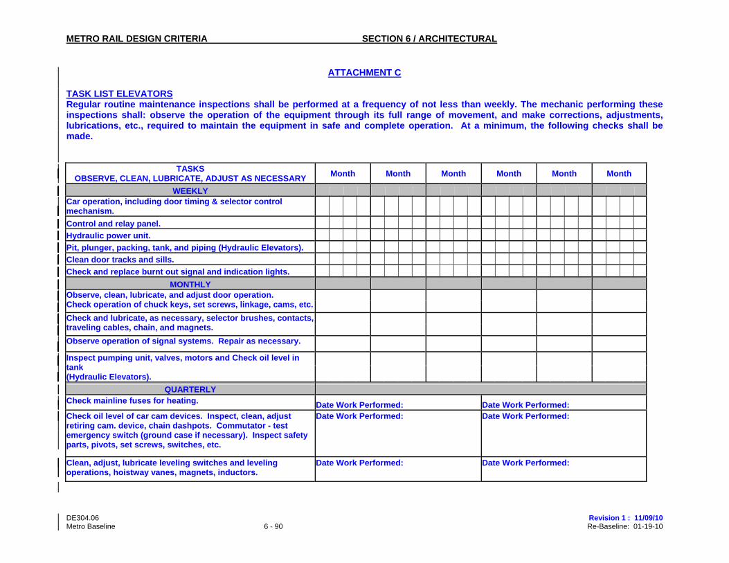
ATTACHMENT C TASK LIST ELEVATORS Regular routine maintenance inspections shall be performed at a frequency of not less than weekly. The mechanic performing these inspections shall: observe the operation of the equipment through its full range of movement, and make corrections, adjustments, lubrications, etc., required to maintain the equipment in safe and complete operation. At a minimum, the following checks shall be made.
TASKS OBSERVE, CLEAN, LUBRICATE, ADJUST AS NECESSARY
Month Month Month Month Month Month
WEEKLY Car operation, including door timing & selector control mechanism.
Control and relay panel.
Hydraulic power unit.
Pit, plunger, packing, tank, and piping (Hydraulic Elevators).
Clean door tracks and sills.
Check and replace burnt out signal and indication lights.
MONTHLY Observe, clean, lubricate, and adjust door operation.
Check operation of chuck keys, set screws, linkage, cams, etc. Check and lubricate, as necessary, selector brushes, contacts,
traveling cables, chain, and magnets. Observe operation of signal systems. Repair as necessary.
Inspect pumping unit, valves, motors and Check oil level in tank (Hydraulic Elevators).
QUARTERLY Check mainline fuses for heating. Date Work Performed: Date Work Performed: Check oil level of car cam devices. Inspect, clean, adjust retiring cam. device, chain dashpots. Commutator - test emergency switch (ground case if necessary). Inspect safety parts, pivots, set screws, switches, etc.
Date Work Performed: Date Work Performed:
Clean, adjust, lubricate leveling switches and leveling operations, hoistway vanes, magnets, inductors.
Date Work Performed: Date Work Performed:
METRO RAIL DESIGN CRITERIA SECTION 6 / ARCHITECTURAL
DE304.06 Revision 1 : 11/09/10 Metro Baseline 6 - 91 Re-Baseline: 01-19-10
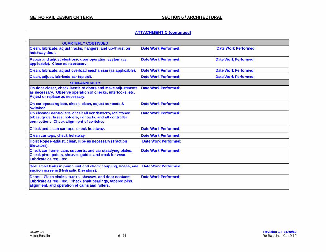
ATTACHMENT C (continued)
QUARTERLY CONTINUED Clean, lubricate, adjust tracks, hangers, and up-thrust on hoistway door.
Date Work Performed: Date Work Performed:
Repair and adjust electronic door operation system (as applicable). Clean as necessary.
Date Work Performed: Date Work Performed:
Clean, lubricate, adjust overload mechanism (as applicable). Date Work Performed: Date Work Performed:
Clean, adjust, lubricate car top exit. Date Work Performed: Date Work Performed:
SEMI-ANNUALLY On door closer, check inertia of doors and make adjustments as necessary. Observe operation of checks, interlocks, etc. Adjust or replace as necessary.
Date Work Performed:
On car operating box, check, clean, adjust contacts & switches.
Date Work Performed:
On elevator controllers, check all condensers, resistance tubes, grids, fuses, holders, contacts, and all controller connections. Check alignment of switches.
Date Work Performed:
Check and clean car tops, check hoistway. Date Work Performed:
Clean car tops, check hoistway. Date Work Performed:
Hoist Ropes--adjust, clean, lube as necessary (Traction Elevators).
Date Work Performed:
Check car frame, cam. supports, and car steadying plates. Check pivot points, sheaves guides and track for wear. Lubricate as required.
Date Work Performed:
Seal small leaks in pump unit and check coupling, hoses, and suction screens (Hydraulic Elevators).
Date Work Performed:
Doors: Clean chains, tracks, sheaves, and door contacts. Lubricate as required. Check shaft bearings, tapered pins, alignment, and operation of cams and rollers.
Date Work Performed:
METRO RAIL DESIGN CRITERIA SECTION 6 / ARCHITECTURAL
DE304.06 Revision 1 : 11/09/10 Metro Baseline 6 - 92 Re-Baseline: 01-19-10
ATTACHMENT C (continued)
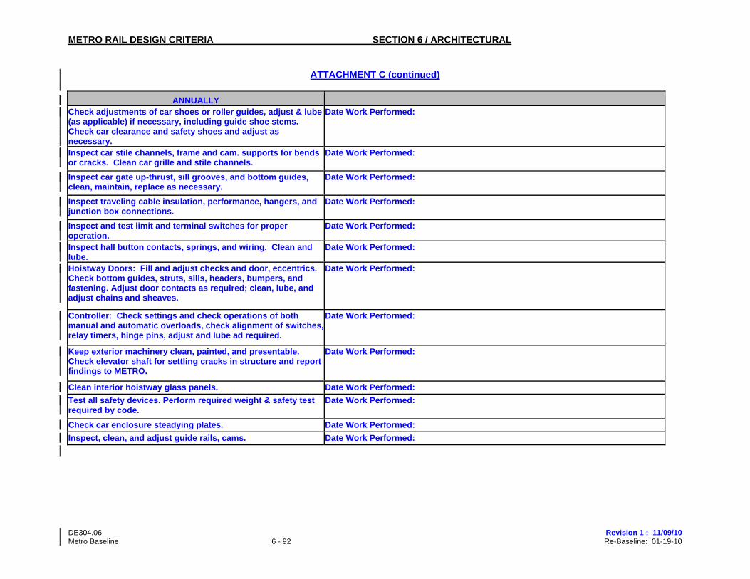
ANNUALLY Check adjustments of car shoes or roller guides, adjust & lube (as applicable) if necessary, including guide shoe stems. Check car clearance and safety shoes and adjust as necessary.
Date Work Performed:
Inspect car stile channels, frame and cam. supports for bends or cracks. Clean car grille and stile channels.
Date Work Performed:
Inspect car gate up-thrust, sill grooves, and bottom guides, clean, maintain, replace as necessary.
Date Work Performed:
Inspect traveling cable insulation, performance, hangers, and junction box connections.
Date Work Performed:
Inspect and test limit and terminal switches for proper operation.
Date Work Performed:
Inspect hall button contacts, springs, and wiring. Clean and lube.
Date Work Performed:
Hoistway Doors: Fill and adjust checks and door, eccentrics. Check bottom guides, struts, sills, headers, bumpers, and fastening. Adjust door contacts as required; clean, lube, and adjust chains and sheaves.
Date Work Performed:
Controller: Check settings and check operations of both manual and automatic overloads, check alignment of switches,relay timers, hinge pins, adjust and lube ad required.
Date Work Performed:
Keep exterior machinery clean, painted, and presentable. Check elevator shaft for settling cracks in structure and report findings to METRO.
Date Work Performed:
Clean interior hoistway glass panels. Date Work Performed:
Test all safety devices. Perform required weight & safety test required by code.
Date Work Performed:
Check car enclosure steadying plates. Date Work Performed:
Inspect, clean, and adjust guide rails, cams. Date Work Performed: