Embed Size (px)
Citation preview
Second-law based thermodynamic analysis ofBrayton/Rankine combined power cycle
with reheat
A. Khaliqa,*, S.C. Kaushikb
aDepartment of Mechanical Engineering, Faculty of Engineering and Technology, Jamia Millia Islamia,New Delhi 110025, India
bCentre for Energy Studies, Indian Institute of Technology, New Delhi 10016, India
Accepted 3 August 2003
Abstract
The aim of the present paper is to use the second-law approach for the thermodynamicanalysis of the reheat combined Brayton/Rankine power cycle. Expressions involving thevariables for specific power-output, thermal efficiency, exergy destruction in components ofthe combined cycle, second-law efficiency of each process of the gas-turbine cycle, and second-law efficiency of the steam power cycle have been derived. The standard approximation for airwith constant properties is used for simplicity. The effects of pressure ratio, cycle temperature-ratio, number of reheats and cycle pressure-drop on the combined cycle performanceparameters have been investigated. It is found that the exergy destruction in the combustionchamber represents over 50% of the total exergy destruction in the overall cycle. The com-bined cycle efficiency and its power output were maximized at an intermediate pressure-ratio,and increased sharply up to two reheat-stages and more slowly thereafter.
1. Introduction
A development in the search for higher thermal-efficiency of conventional powerplant has been the introduction of combined-cycle plants. This is leading to thedevelopment of gas turbines dedicated to combined-cycle applications, which hasbeen a subject of great interest in recent years, because of their relatively low initial

180 A. Khaliq, S.C. Kaushik/ Applied Energy 78 (2004) 179-197
Nomenclature
CpehnPQRSgesWwJTAC
Y
>/l,Comb
>?2,Comb
eAhfAHf
Specific heat at constant pressure (kJ/kg K)Specific exergy (kJ/kg)Specific enthalpy (kJ/kg)Number of reheat stagesPressure (kPa)Heat per unit mass of fuel (KJ/kg)Gas constant (KJ/kg-K)Entropy generation rate (W/K)Specific entropy (KJ/kg)Work per unit mass of gas (KJ/kg)Dimensionless specific exergy/work (w = e/CpT0)Pressure ratio across the compressorRatio of specific heatsFirst-law efficiency of gas-turbine cycleFirst-law efficiency of combined cycleSecond-law efficiency of combined cycleMaximum to minimum cycle temperature ratio (6= T3/T0)Dimensionless heat-input (AH{/CPTQ)
Heat input or enthalpy of reaction at standard condition (KJ/kg)
costs, and the short time needed for their construction. An optimum system for agiven power-generation duty may involve alternate cycle configurations, such ascompressor intercooling, turbine reheat, and steam injection into the gas turbinecombustor.
The early development of the gas/steam turbine plant, was described by Sieppeland Bereuter [1]. Czermak and Wunsch [2] carried out the elementary thermo-dynamic analysis for a practicable Brown Boveri 125 MW combined gas-steamturbine power plant. Wunsch [3] claimed that the efficiencies of combined gas-steamplants were more influenced by the gas-turbine parameters like maximum tempera-ture and pressure ratio than by those for the steam cycle and also reported that themaximum combined-cycle efficiency was reached when the gas-turbine exhausttemperature is higher than the one corresponding to the maximum gas-turbine effi-ciency. Horlock [4], based on thermodynamic considerations, outlined more recentdevelopments and future prospects of combined-cycle power plants. Wu [5] describethe use of intelligent computer software to obtain a sensitivity analysis for the com-bined cycle. Cerri [6] analyzed the combined gas-steam plant, without reheat, fromthe thermodynamic point of-view. In his analysis, he singled out the parameters thatmost influence efficiency, and further reported that combined cycles exhibit a goodperformance if suitably designed, but if the highest gas-turbine temperatures areused, expensive fuel must be utilized.

A. Khaliq, S.C. Kaushik/ Applied Energy 78 (2004) 179-197 181
Reheat has been widely employed in aircraft engines. However, for industrialgas-turbines, it is a technique that has only recently reached the stage of beingconsidered a viable option for power augmentation. For a fixed overall pressure-ratioand given power, the advantage of using reheat is that the turbine's entry tempera-ture (TET) corresponding to the main combustor and reheater of the reheat cycle islower than the TET of a simple cycle. Hence, the costs related to the use of expensivesuperalloys to withstand high temperatures could be reduced as described by Cunhaet al. [7]. There is a reduction in efficiency, since more fuel is injected at a lowerpressure so producing less power than that which would be obtained if all the fuelwere injected in the main combustor. In combined-cycle applications, the increasedamount of heat in the exhaust gas is not actually lost and it may improve thecombined-cycle characteristics. Andriani et al. [8] carried out the analysis of a gasturbine with several stages of reheat for aeronautical applications. Polyzakis [9]carried out the first-law analysis of reheat industrial gas-turbines use in a combinedcycle and suggested that the use of reheat is a good alternative for combined-cycleapplications. But the performance analysis based on the first-law alone is inadequateand a more meaningful evaluation must include a second-law analysis. One reasonthat such an analysis has not gained much engineering use may be the additionalcomplication of having to deal with the ‘‘combustion irreversibility’’, which intro-duced an added dimension to the analysis. Second-law analysis indicates the associ-ation of exergy destruction with combustion and heat-transfer processes and allowsa thermodynamic evaluation of energy conservation in thermal power cycles.
It became apparent to the current authors that, although there was sufficientliterature on combined power-cycle with reheat, no systematic second-law analysisof these cycles has been reported. The objective of the present paper is to develop asystematic and improved second-law based thermodynamic methodology for theanalysis of reheat combined gas-steam power plant.
2. System description
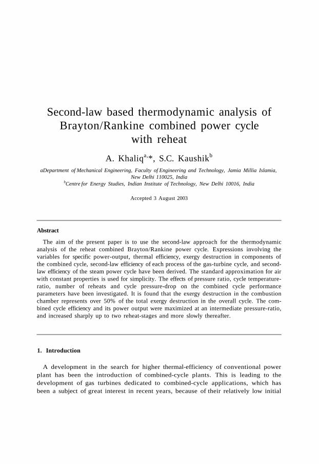
A schematic diagram of a combined Brayton/Rankine power cycle with reheat is shownin Fig. 1. The gas turbine is shown as a topping plant, which forms the high-tempera-ture loop, whereas the steam plant forms the low-temperature loop. The connectinglink between the two cycles is the heat-recovery steam generator (HRSG) working onthe exhaust of the gas turbine. A gas-turbine cycle consists of an air compressor (AC), acombustion chamber (CC) and a reheat gas-turbine (RGT). The turbine's exhaust-gasgoes to a heat-recovery steam-generator to generate superheated steam. That steam isused in a standard steam power-cycle, which consists of a turbine (ST), a condenser(C) and a pump (P). Both the gas and steam turbines drive electric generators.
3. Thermodynamic analysis
For the system operations in a steady state, the general exergy-balance equation isgiven by Bejan [10]

182 A. Khaliq, S.C. Kaushik / Applied Energy 78 (2004) 179-197
6D.CC cf,cr
:D,AC
4e = 0
CombustionChamber
Compressor
WR0T
Reheat Gas Turbine
WAC
Heat RecoverySteam Generator
Steam Turbine
6 V 4
eD,p
Condenser
eD,c
Fig. 1. Schematic diagram of the combined Brayton/Rankine power cycle with reheat.
(1)
(2)
After making exergy balances using Eq. (2) for the compressor, reheat turbine andcombustion chamber, the following expressions can be obtained
= {ei - e 1 eD;AC ð3Þ
in out
for a single-stream flow
EW = EQ þ mem - meoai -
ef;CC = {e-i - e 2 eD;CC (4)
= (e4 - e 3 WRGT þ ED ; (5)
where WAC and WRGT are the work done per unit mass for the compressor andreheat gas-turbine respectively and 'e' is the specific exergy
The net work-output of the gas-turbine cycle is
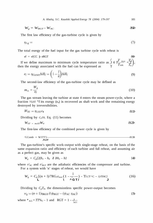
A. Khaliq, S.C. Kaushik/ Applied Energy 78 (2004) 179-197 183
Wg = WRGT - WAC ð6Þ
The first law efficiency of the gas-turbine cycle is given by
The total exergy of the fuel input for the gas turbine cycle with reheat is
ef = ef;CC þ eRGT ð8Þ
If we define maximum to minimum cycle temperature ratio as I 6 T max = Tthen the exergy associated with the fuel can be expressed as T mm °
(9)
The second-law efficiency of the gas-turbine cycle may be defined as
m,s = — (10)
The gas stream leaving the turbine at state 4 enters the steam power-cycle, where afraction ??2,ST °f its exergy (e4) is recovered as shaft work and the remaining exergydestroyed by irreversibilities.
ð11Þ
Dividing by CPT0, Eq. (11) becomes
WST = m,STW4 ð12Þ
The first-law efficiency of the combined power cycle is given by
^l.Comb = W I T T } ð13ÞAiif
The gas-turbine's specific work-output with single-stage reheat, on the basis of thesame expansion ratio and efficiency of each turbine and full reheat, and assuming airas a perfect gas, may be given as
Wg = Cp[2(h3 - h4 ð Þh2 - h1 14Þ
where r/AC and r/RGT are the adiabatic efficiencies of the compressor and turbine.For a system with 'n' stages of reheat, we would have
Wg = Cp [(n + l)/7RGTrmax (1 - — — ) - Ti (T^C - 1)/TIAC] (16)L \ ^ G T / J
Dividing by CpT0, the dimensionless specific power-output becomes
17Þ
where * A C = TT%C - 1 and RGT = 1 - -J—

184 A. Khaliq, S.C. Kaushik/ Applied Energy 78 (2004) 179-197
The fuel input or heat input (AHf or Qin) per unit mass of the cycle for the singlestage with full reheat is given by
Qin = [Aflf.cc þ DHf;RGT ð18Þ
For a perfect gas, it may be expressed as
[ T "1
Tmax — T1 2AC þ 7?RGT Tmax ty RGT ð19ÞriAC þ
F o r 'n ' reheat stage, i t becomes
[ TAAC 1
max ^ ^ max jDividing by CpT0, Eq. (20) may be written as
qin = 6 - 1 - ifAchhc þ ^RGT^IARGT ð21Þ
Using Eqs. (17) and (21), the first-law efficiency of the gas-turbine cycle becomes
_ Wj_ _ (n + l^RGT^RGT - jJAc/rjAC . - - .
Using Eqs. (12), (13), (17) and (21), the first law efficiency of the combined cyclemay be expressed as
, _ ðÞn þ l^RGT^RGT ^AC/>?2,STW4]
[ 8 - 1 - f A c h h c + n t ] R G T . 6 . I A ]
This shows that the first-law efficiency of the combined cycle is a function oftemperature ratio '0', compressor's pressure-ratio ‘ A C ' , number of reheat stages'n'and the pressure drop in the heat-transfer devices.
The second-law efficiency of combined cycle may be defined as
?72, comb = W g þ = — : (24)ef 'ICarnot
Using Eqs. (23) and (9) in Eq. (24),
, _ [(" + ^^RGT^^RGT - fhchhC + ^l.ST^] , ., c o m _ [ e l } J / / i i + n m H ] ( e l ) ( )
where w4 = T4— 1 -lnr4.
Relation between compressor and turbine pressure-ratios
The turbine expansion ratio 7rRGT may be expressed in terms of the compressionratio and the pressure drop in each of the heat-transfer devices, involved. Ifpin, andpout are the inlet and outlet pressures for each heat-transfer device, then

A. Khaliq, S.C. Kaushik/ Applied Energy 78 (2004) 179-197 185
pout = PPin ð26Þ
The quantity Ap/p is known as the relative pressure-drop and b may be called thepressure-drop factor.
If pcc is the pressure-drop factor or percentage pressure-drop in the combustionchamber, y6R in reheater and /Jg in heat recovery steam-generator, then
p3 = PccP2 ð27Þ
pRo = PRiPR ð28Þ
pgo = PgPgi ð29Þ
Combining Eqs. (27)-(29), we have
The traditional first-law efficiency of a steam turbine cycle is
Now
p3 pRo— =
For a system with one stage of reheat,
ð31Þ
1=2ð32Þ
For two reheat-stages,
)) ð33Þ
For n reheat-stages,
= (PccPnRPg7tAcy
/(n+r) (34)
ð35Þ

186 A. Khaliq, S.C. Kaushik/ Applied Energy 78 (2004) 179-197
Its second-law efficiency has been defined by Eq. (11). Thus the ratio of its second-law efficiency to its first law efficiency is just the ratio of the heat supplied to theHRSG per unit mass of hot gas to the specific exergy of the hot gas entering theHRSG. If the gas with a constant specific heat, enters the boiler at T4 and leaves atTex, then
7?2,ST WST QST QST
For a constant-pressure process, by dividing by CpT0
*/2, ST ^4 ^6x
ð36Þ
This is computed in Table (9) versus T4 with re x as the variable parameter. Thesecond-law efficiency of the steam-turbine cycle is larger than the first-law efficiencyso long as T 4 < 1 + lrrr4, a condition satisfied in any practical steam-turbine bottom-ing cycle.
For the purpose of combined cycle efficiency computations presented based onEqs. (23) and (25), the second-law efficiency of the steam-turbine cycle was assumedto follow the trend shown in Fig. A 1 , which was plotted using the correlationdeveloped in the Appendix. The second-law efficiency (??2,ST) is zero for T 4 < 2 , wherethe steam-turbine cycle was judged impractical linearly from 4 8 % at T4 = 2 to 70%at T 4 = 3 . 2 5 , and constant at 70% for 5 > T 4 > 3 . 2 5 .
5. Evaluation of component's exergy destructions
5.1. Compressor (AC)
The second-law efficiency of a compression process (1-2) is the ratio of theincreased exergy to the work input: thus
»72,AC = ^ ^ (38)
For frictionless reversible adiabatic or isothermal compressions, no entropy isgenerated or exergy destroyed and ??2,AC=1- In a real compressor of adiabaticefficiency r/AC, for an infinitesimal adiabatic increase in pressure dp, the temperatureincrease dT is greater than the isentropic value dTs.
ð39Þ7?AC
For a perfect gas using the isentropic relation, we have
d ^ = H d pT y p

A. Khaliq, S.C. Kaushik/ Applied Energy 78 (2004) 179-197 187
The canonical relation is
ð41ÞT p
Using Eqs. (39) and (41), the entropy generated during the compression process is
dsgen = Cp —- - R — (42)VAC p
Using Eqs. (40) and (42), we have
ds =??AC
The exergy destroyed is obtained after multiplying Eq. (43) by T0 and thenintegrating. After non-dimensionalizing by dividing with CpT0, the dimensionlessexergy destruction may be given as
nr ð44Þ
Eq. (44) accounts for the exergy destroyed within the compressor. The compressorwork for the infinitesimal adiabatic stage is CpdT. After using Eqs. (39) and (40) fora perfect gas, the compressor work in dimensionless form may be given as
c C 1 T0 p
Unlike the exergy destroyed, this depends on the local temperature. Thecompression work for adiabatic compression may be obtained by using Eqs. (40)and (45) as
wAC;ad = rV"A C - 1 ð46Þ
Applying the exergy balance and using Eq. (38), the corresponding second-lawefficiency for the adiabatic compression process may be given by
/ 1 J 7 A C \ ‘nr= 1 - 1 -nz-c r ð47Þ
5.2. Combustion chamber (CC)
The heat addition in the combustion chamber (A//fCC) may be defined as
DHf ; CC = - = CpðÞðT3 - T2 48Þm
After dividing Eq. (48) by CpT0, it may be expressed as

188 A. Khaliq, S.C. Kaushik/ Applied Energy 78 (2004) 179-197
AAf.cc =0-r2 (49)
The exergy associated with AHfcc is
ef;CC = DHf;CCðÞð1 - 1/6) 50Þ
Using Eq. (49) and dividing Eq. (50) by CpT0, the dimensionless exergy associatedwith fuel may be obtained as
(8 - 1)(0 - T2)Wf,cc = 2 (51)
The increase in exergy per unit mass of fuel is given by
e3 - e2 = (h3 - h2T 0 ðÞðs3 - s2 52Þ
After dividing by CpT0 and using Eqs. (41), (49) and (26), it may further beexpressed as
w3 - w2 = 6 - T2 - ‘n — þ alnficc ð53Þ
The dimensionless exergy destruction (wD j Cc) in the combustion chamber can beexpressed using Eqs. (3) and (53), as
T f)fi ~ 1 ð54Þ
0 T2
The second-law efficiency for the combustion chamber is the ratio of the increasedexergy over the exergy input and is given by
w3 - w2T?2,CC = (55)
wf;CC
Using Eqs. (49) and (53),
e1 - T2 - in h
This shows that the second-law efficiency of the combustion chamber depends onthe compressor's discharge temperature, pressure-drop in the combustion chamberand the maximum cycle temperature.
5.2.1. Reheat gas-turbine (RGT)For an adiabatic expansion in a turbine with an adiabatic efficiency r]RGT,
the temperature-drop dT for a pressure drop dp is smaller than the correspondingisentropic value dTs.
dT
dfs ( 5 7 )

A. Khaliq, S.C. Kaushik/ Applied Energy 78 (2004) 179-197 189
Using Eqs. (40), (41) and (43), we see that the entropy generated in the adiabaticstage is
dpdsgen = (1 - ^ R G T ) ^ — ð58Þ
By multiplying Eq. (58) by T0 and integrating, and, thereafter dividing by CpT0,the exergy destruction may be obtained as
= (1 - r]RGT)lnr ð59Þ
It accounts only for exergy destroyed within the turbine but not for reheatpressure-losses or heat-transfer losses. The expansion work CpdT, after using Eqs.(57) and (40), may be expressed as
( y - D , - - » (60)Y 3 T0 p
and depends on the pressure-temperature path. For the adiabatic expansion startingat T3 after integrating Eq. (60) and using (0 = T3/T0), it may also be expressed as
wRGT;ad = 0(1 - f-"RGT) 61Þ
The second-law efficiency of the expansion process is the ratio of work outputover decrease in the exergy of the gas, and is given by
wRGT ,r^??2,RGT = (62)
w3 - w2 þ W
Using Eqs. (61), (53) and (62), the second-law efficiency of the expansion processin the gas turbine cycle may be given as
ð63Þ
This shows that the second-law efficiency of the reheat gas-turbine increases with ysince a larger proportion of the available work lost at higher temperatures may berecovered.
6. Optimum pressure-ratio
The optimum pressure ratio for maximum work output of a gas turbine, takinginto account the adiabatic efficiencies of the compressor and turbine, can beobtained by differentiating Eq. (17), w.r.t. p AC as
ð64Þ

190 A. Khaliq, S.C. Kaushik/ Applied Energy 78 (2004) 179-197
This gives
(^Ac)opt= { T ^ — ) (65)
This shows that the optimum pressure-ratio depends on the adiabatic efficienciesof the turbine and compressor, as well as the cycles temperature-ratio.
7. Numerical results and discussion
Based upon the methodology developed and the equations derived here, thecombined-cycle efficiency, exergy destruction as well as the second-law efficiency ofeach process have been evaluated.
For the results, we made the following assumptions; adiabatic efficiencies ofcompressor and gas turbine are 0.9 and 0.85, respectively; pressure drops in theprimary combustor are 3%, in each reheater 2% and in the HRSG 4%. The gas isassumed to have constant properties with y= 1.4, R = 287 J/kg K. For illustration ofthe results, the pressure ratio was taken as 32, cycle-temperature ratio as 5, tworeheats and no intercooling.
Table 1 shows the variation of performance parameters of the compressor and gasturbine with the pressure ratio. The second-law efficiency of the adiabatic com-pressor increases with pressure ratio because the absolute values of the work inputand exergy increase are both larger and the magnitude of exergy destruction in theadiabatic compressor increases with the increase in pressure ratio.
It is also seen from Table 1 that, the first-law efficiency of the adiabatic turbineincreases with the increase in pressure ratio. The second-law efficiency decreases withthe pressure ratio, but increases with the cycle temperature ratio since a greaterproportion of the available work lost at the higher temperature may be recovered.The exergy destruction in the reheat turbine increases with the pressure ratio, thenumber of reheat stages and the pressure drop in each reheater as shown in Table 2.
Table 3(a) and (b) show that the first-law and second-law efficiencies of thecombined cycle increases up to the pressure ratio of 32, then they start decreasingwith increases in the pressure ratio. But it is interesting to note that the second-lawefficiency of the combined cycle is greater than the first-law efficiency for samepressure-ratio.
Table 4 shows that if the pressure ratio is too low, then the gas-turbine cycle andcombined-cycle efficiencies and their specific work-outputs drop, whereas the steamcycle work-output increases due to the high gas-turbine exhaust temperature T4. Atan intermediate pressure-ratio, both the efficiency and specific work peak. If thepressure ratio is too high, the compressor and turbine works increase but theirdifference, the net gas-turbine work output drops. The absolute magnitude of exergydestroyed in both compressor and turbine increases as the logarithm of pressureratio. The exergy lost in the reheat turbine also increases due to the lower mean

A. Khaliq, S.C. Kaushik/ Applied Energy 78 (2004) 179-197 191
Table 1Table 1Effect of pressure ratio on the performance of compressor and gas turbine
1248
163264
128
1.0001.2191.4851.8112.2082.6913.2813.999
>?1,AC
0.9000.8900.8800.8700.8600.8500.8320.820
wD,AC
0.0000.0220.0430.0660.0880.1100.1320.154
0.9000.9100.9200.9290.9370.9450.9510.957
TRGT
0.0001.1511.3691.6281.762.3032.7393.257
0.9851.0411.0941.1491.1751.2691.3331.401
il.RGT
0.0000.8620.8720.8830.8940.9040.9120.2070
WD,RGT
0.0000.0290.0590.0890.118
-0.1480.1780.207
12.RGT
0.9950.9550.9410.9240.9030.8760.8440.806
Table 2Effect of number of reheat stages (n) and pressure drops in the reheater (/JR) on the exergy destruction inthe reheat gas-turbine
Number ofreheat stages (n)
wD,RGT
0.14850.22570.22030.21070.20230.19540.19080.1858
0.14850.23310.22770.22230.22010.21770.21660.2173
0.14850.23800.23890.24070.24410.24970.25650.2643
temperature of reheat. The steam-turbine cycle output suffers with the lowerexhaust-gas temperature. The second-law efficiency of each cycle is greater than thefirst-law efficiency for the given operating parameters.
It is seen from Table 5 that the exergy destruction in the combustion chamberdecreases with the pressure ratio, but increases with the cycle temperature ratio y,and the second-law efficiency of the primary combustor behaves in reverse as isknown from the second-law analysis.
The exergy destructions due to heat-transfer irreversibility (HRSG), condenser-heat rejection, irreversibilities of the steam turbine and pump, and the first-lawefficiency of the steam turbine cycle increase with an increase in the gas-turbine'sexhaust temperature, but the second-law efficiency declines with an increase in theexhaust-gas's temperature above the minimum temperature that can operate thesteam cycle. This minimum gas temperature is constrained by the required superheatsteam and or the pinch point on the HRSG as shown in Table 8.
Table 6 shows that increasing the maximum cycle temperature gives a significantimprovement in both efficiency and specific work-output. The gas-turbines cycleefficiency drops, but its net specific work-output increases with the number of reheatstages. Both efficiency and specific work increase with the increase in number of

192 A. Khaliq, S.C. Kaushik/ Applied Energy 78 (2004) 179-197
Table 3(a) Effect of pressure ratio (TZAC) and cycle temperature ratio (6) on the first-law efficiency of the combinedcycle for two stages of reheat. (b) Effects of pressure ratio (PAC) and cycle temperature ratio (6) on thesecond-law efficiency of the combined cycle for two stages of reheat
7TAC
(a)8
163264
128
(b)8
163264
128
1.9202.423.0483.8404.838
1.9202.423.0483.8404.838
u — 4
T 4
3.4133.2273.0502.8802.727
3.4133.2273.0502.8802.727
il.Comb
51.152.350.746.738.0
68.1369.7367.662.2650.66
0 = 4.5
T 4
3.8403.6303.4333.60653.068
3.8403.6303.4333 . 53.068
il.Comb
53.7055.7656.3654.8049.00
69.1171.7672.5370.5263.06
0 = 5
T 4
4.2674 . 43.8143.6063.409
4.2674 . 43.8143.6063.409
1l,Comb
55.8058.2059.2058.8056.50
69.7572.7574.073.570.62
0=5.5
T 4
4.694.4384.1953.9603.750
4.694.4384.1953.9603.750
il.Comb
57.560.061.4561.6560.30
70.3073.3575.1275.3673.71
0 = 6
T 4
5.04.844.574.123.72
5.04.844.574.123.72
Vi,
5961636363
7073757675
,Comb
.0
.57
.23
.80
.20
.80
.80
.80
.56
.84
Table 4Effect of pressure ratio on the first-law and second-law efficiencies of various cycles
7TAC
8163264
128
Vis
27.833.035.9536.734.4
V2s
34.7541.2544.9345.8743.00
>?1,ST
28.0025.1723.2522.4022.00
»?2,ST
43.8240.1837.8237.1,637.00
1l,Comb
55.8558.1759.258.856.40
i2,Comb
69.8172.7174.0073.5070.50
7?Carnot
80.0080.0080.0080.0080.00
reheat stages for the steam cycle which benefits from a higher gas-temperature. Thecombined cycle efficiency and specific work-output increase sharply in going fromone to two reheats and more slowly thereafter, It was interesting to note that thespecific power increases by a factor of 2.5 for the two reheats as shown in Table 7.This may well justify the additional capital cost of the reheat system.
Table 9 shows that the second-law efficiency of steam-turbine cycle is larger thanthe first-law efficiency so long as r < 1 + lnr4, a condition satisfied in any practicalsteam-bottoming cycle. It is shown that the second-law efficiency of a given steamcycle declines with increasing gas-temperature above the minimum that can operatethis cycle. This minimum gas-temperature is constrained by the required steamsuperheat and/or the ‘‘pinch point’’ on the heat exchanger.
Fig. 2 shows the effect of increasing the pressure ratio and the cycle-temperatureratio on the first-law efficiency of the gas-turbine cycle. The increase in pressure ratioincreases the overall thermal efficiency at a given maximum temperature. Howeverincreasing the pressure ratio beyond a certain value at any given maximum

A. Khaliq, S.C. Kaushik/ Applied Energy 78 (2004) 179-197 193
Table 5Effect of pressure ratio (nAC) and cycle temperature ratio (6) on exergy destruction and second lawefficiency of combustion chamber (CC) for two reheats
1248
163264
128
0 = 4
wD,CC
1.6271.4841.3531.2361.1371.0601.0100.990
Vl,CC
0.1330.1630.1920.2140.2150.1760.0580.028
0 = 4.5
wD,CC
1.71.5681.4301.31.35901.1031.0360.997
Vl,CC
0.1261.5500.1860.2100.20.2070.1340.100
0 = 5
wD,CC
1.8001.6471.5021.3681.2481.1481.0681.014
Vl,CC
0.1190.1460.1760.2040.2230.2281.21.14100 . 1
0
M
11111111
= 5.5
D,CC
.877
.719
.570
.439
.305
.195
.103
.036
Vl,CC
0.1120.1380.1670.1960.2190.2280.2060.126
0 = 6
wD,CC
1.9491.4231.6341.43901.3591.2411.1411.062
Vl,CC
0.10660.13170.15900.18800.21400.23000.22100.1680
Table 6Effect of cycle temperature-ratio on efficiencies of various cycles
Temperatureratio '6'
44.55.05.56.06.5
Z1,g
30.3033.7036.0037.6038.8539.80
304043.3345.0046.9546.6247.05
>?1,ST
20.5022.5723.3023.9024.3924.86
»?2,ST
050.8037.9037.9537.8637.6337.50
il.Comb
50.8056.2759.3061.5063.2464.66
*?2,Comb
67.7072.4074.1275.1875.8976.40
^Carnot
75.0077.7080.0081.8083.3384.60
Table 7Effects of number of reheat stages (n) on work output and efficiencies of various cycles
n
012345
>?i,g
43.5037.2836.736.235.935.7
>?1,ST
9.0066.8069.5770.6371.4071.90
il.Comb
52.5057.9059.7760.3360.7561.00
2 . 5 01.4031.6441.761.8281.865
Vfg+H'4
1.5002.1833.1093.4253.633.756
wComb
1.202.182.672.9263.0893.186
1.7003.7624.4694.855.0865.224
>?Camot?m
1.7003.003.5753.8804.0684.180
temperature can actually result in lowering the gas-turbine's cycle efficiency. Itshould also be noted that the very high-pressure ratios tend to reduce the operatingrange of the compressor.
Fig. 3 shows that the maximum work per kilogramme of air occurs at a muchlower pressure-ratio than the point of maximum efficiency for the same maximumtemperature.

194 A. Khaliq, S.C. Kaushik/ Applied Energy 78 (2004) 179-197
Table 8Exergy destruction as a percentage of heat added, in the components of the steam-turbine cycle: T0 = 291K, Tex = 420 K, condenser pressure = 0.045 bar (304 K), steam-turbine efficiency 90%, pump efficiency70%
Exhaust-gastemperature ratio
2.002.252.502.753.003.25
Exhaustavailability
738185889091
Heat-transferirreversibility
131816171613
Condenser lossand rejection
656554
Irreversibilityof turbine andpump
465678
Steam cyclework output
495258616365
Table 9Effects of gas temperature ratio T4 and exhaust temperature ratio Tex on the ratio of efficiencies of thesteam cycle
T 4
23456789
1011
T e x = l
>?2,ST
»?1,ST
3.2582.2181.8591.6731.5581.479---
-
Tex = 1 . 5
>?2,ST
»?1,ST
1.6291.6641.4591.4641.40261.356---
-
Tex = 2.0
>?2,ST
>?1,ST
1.1091.1091.2391.2551.2461.233---
-
Tex = 2.5
>?2,ST
>?1,ST
0.55400.55400.92901.04571.09091.1099---
-
Tex = 3 . 0
»?2,ST
»?1,ST
_
-
0.61960.83660.93500.98661.01601.03391.04501.0523
Tex = 3.5
»?2,ST
>?1,ST
_
-
0.30980.62740.77920.86330.91450.94780.97050.9865
Tex = 4 0
»?2,ST
>?1,ST
_
-
-
0.41800.62300.74000.81290.86160.89580.9207
Thus, a cursory inspection of the efficiency indicates that the gas-turbine cycleefficiency can be improved by increasing the pressure ratio, or increasing theturbine's inlet-temperature.
8. Conclusion
An improved second-law analysis of the combined power-cycle with reheat hasshown the importance of the parameters examined. The analysis has included theexergy destruction in the components of the cycle and an assessment of the effects ofpressure ratio, temperature ratio and number of reheat stages on the cycle perfor-mance. The exergy balance or second-law approach presented facilitates the designand optimization of complex cycles by pinpointing and quantifying the losses. By

A. Khaliq, S.C. Kaushik/ Applied Energy 78 (2004) 179-197 195
10 15
800 degree C1300 degree C
20Pressure ratio- 1000 degree C- 1350 degree C
25 30 35 40
1200 degree C1400 degree C
Fig. 2. Effect of pressure ratio and turbines inlet temperature on the first-law efficiency of the gas-turbinecycle.
1 2 3 4 5 6Maximum to minimum gas-turbine cyle temperature ratio
Fig. 3. Pressure ratio for maximum work per kg of air.
placing reheat in the expansion process, significant increases in specific power outputand efficiency were obtained. The gains are substantial for one and two reheats, butprogressively smaller for subsequent stages. It is interesting to note that specificpower output (per unit gas flow) increases by a factor of 2.5 for the two reheats. Thismay well justify the additional capital cost of the reheat system. Reheating byincreasing the specific power-output reduces the sensitivity of the cycle to componentlosses.

196 A. Khaliq, S.C. Kaushik/ Applied Energy 78 (2004) 179-197
Appendix. Correlation for the second-law efficiency of the steam cycle
For a simple steam-cycle, the maximum second-law efficiency can be correlatedwith the gas temperature T4 for a fixed exhaust-gas temperature Tex.
To find this correlation, calculations were done for several values of the tempera-ture T4. In each case, the steam-turbine cycle pressure and peak temperature T5,ST
were first determined by setting the pinch point (saturation) and maximum steam-temperatures at 5 and 20 K below the corresponding gas-temperature profile. Thusthe percentage of gas and steam enthalpies above the pinch point must be the same,giving
5°)ðA1Þ
which may be solved iteratively for the steam-turbine cycle pressure. In the followingcalculations, the assumptions are:
75
70
65
I-aao
60
55
a 50
oo
45
40
/
/
/
12
456
Pressure9.1
13.724.040.070.0
120.0
Temperature T5 ST (K)563633703873843923
Efficiency %27.129.632.735.338.140.6
2 2.5 3 3.5 4 4.5 5
Temperature ratio of gas supplied to boiler (x4)5.5
Fig. A1. Second-law efficiency correlation for bottoming cycle.

A. Khaliq, S.C. Kaushik/ Applied Energy 78 (2004) 179-197 197
1. Ambient temperature T0 = 291 K2. Exhaust temperature Tex = 420 K3. Condenser pressure 0.045 bar (304 K)4. Steam turbine and feed water pump have efficiencies 90 and 70% respectively.5. Saturation temperature (Tsat) = Tex-22 °C.
For each T4, these assumptions were applied, the pressure was found using Eq.(A1) and the second-law efficiency (/?2,ST) is computed and is shown in Fig. A1,which also shows the steam conditions and efficiency computed for each point.
References
[1] Sieppel C, Bereuter R. The theory of combined steam and gas-turbine installation. Brown BoveriReview 1960;47:83-799.
[2] Czermak H, Wunsch A. The 125 MW combined cycle plant design features, plan performance andoperating experience paper no. 82 GT-323]. ASME; 1982.
[3] Wunsch A. Highest efficiencies possible by converting gas-turbine plants into combined cycle plants.Brown Boveri Review 1985;10:455-63.
[4] Horlock JH. Combined power plants—past, present, and future. Trans ASME, Journal of Engng forGas Turbine and Power 1995;117:608-16.
[5] Wu C. Intelligent computer-aided sensitivity analysis of multi-stage Brayton/Rankine combinedcycle. Energy Conv Mgmt 1999;40:215-32.
[6] Cerri G. Parametric analysis of combined gas-steam cycles. Trans, ASME J Engng Gas TurbinePower 1987;109:46-54.
[7] Cunhas Alves MA, da Franca Mendes Carniero HF, de Barbosa JR, Travieso LE, Pildis P. Aninsight on inter-cooling and reheat gas-turbine cycles. Proc Instn Mech Engnrs J Power Energy 2001;215A.
[8] Andriani R, Ghezzi U, Anntoni LFG. Jet engines with heat addition during expansion: a perfor-mance analysis paper 99-0744]. AIAA; 1999.
[9] Polyzakis A. Industrial gas-turbine for combined cycle plant. MSc thesis, Cranfield University, 1995.[10] Bejan A. Fundamentals of exergy analysis, entropy generation minimization, and the generation' of
flow architecture. Int J Energy Res 2002;26:545-65.