Embed Size (px)
Citation preview

Pure appl. geophys. 157 (2000) 357–3820033–4553/00/030357–26 $ 1.50+0.20/0
Second Generation of Lead-lead Chloride Electrodes forGeophysical Applications
GILBERT PETIAU1
Abstract—A large number of geophysical applications need long-term telluric recordings. In orderto realise it correctly, the use of very stable electrodes is necessary. The study of the potential variationsof Pb-PbCl2 electrodes as a function of both the ionic composition and the pH of its electrolyte allowsone to chose the optimal working criteria. The best stability and the minimum noise for the potential areobtained for a solution saturated in both salts PbCl2 and KCl, or PbCl2 and NaCl, in the presence ofadditional non-dissolved salts, with a pH from 4 to 5. The study of the salts diffusion between the insideof the electrode and the outside medium allows one to compute the time span over which the potentialremains stable (tD time of dissaturation), and to know how to increase it. Two solutions are possible.The first one is to increase the electrode length, because tD is proportional to the length squared. Thesecond one is to reduce the exchanges of salts with the external medium, by using an electrode with anarrow channel. In this case, tD is proportional to the quantity of non-dissolved salt in the electrode andto the internal electrical resistance of the electrode. The fabrication of this new electrodes design with achannel is described.
Key words: Telluric survey, magnetotelluric survey, lead-electrodes, electrode chemistry, long-termstability.
1. Introduction
Impolarizable electrodes are used to measure the potential differences betweentwo points of ionic conductors (encountered in chemistry, biology, and, in our case,geophysics). They are essentially made up of a metal in contact with a salt solutionof this metal. Between the various metal-salt couples, we have retained Pb-PbCl2(PETIAU and DUPIS, 1980).
In the present study we make a detailed analysis of the potential of Pb-PbCl2electrodes potential in terms of the concentrations of the principal salt (PbCl2), ofthe auxiliary salt (KCl or NaCl), and of the internal pH. The aim is to find domainswhere this potential is particularly stable. We also study the salt diffusion betweenthe inside of the electrodes and the external medium in order to estimate andimprove their long-term stability in the ground.
1 Institut de Physique du Globe de Paris, Observatoire Magnetique, Carrefour des 8 Routes 45340Chambon La Foret, France. Fax: (33) 02 38 33 95 04.

Gilbert Petiau358 Pure appl. geophys.,
Let us recall that the main part of the potential of an electrode is given by theNernst formula:
E=E0+RTnF
ln aM+n (1)
activity of the metal ion (concentration which actually acts in solution)aM+n
standard potential at 25°E0
R Constant of the perfect gasT absolute temperature
Faraday constantFmetal valencyn
with RT/F=25.7 mV at 25°C.An electrode of the first kind is essentially made of a metal in contact with a
solution of a salt of this metal. If the metal salt, for example, MXn (M+n cation,X− anion) is very weakly soluble, and if the solution is saturated with a supplementof non-dissolved salt, adding another salt containing the same anion X− makes anelectrode of the second kind. The concentration of the M+n ions is then defined bythe relation:
[M+n]=Ks/[X−]n (2)
where Ks is a constant (the solubility product) and [X−] is the total concentrationof the X− ions in the solution originating from both the metal salt and the addedsalt. When the metal salt is very weakly soluble, the addition of a second salt isindeed necessary in order to obtain a correct conductivity of the electrolyte.
Let us underline that the presence of other ions in the solution can also modifythe electrode potential, (1) by changing the cation concentration or the activity ofthe metal [M+n] (hydration, formation of complexes), (2) by oxidising or reducingeffects, (3) by modifying the pH. Moreover, in the presence of a cation of a metalwhich is less oxidisable than that of the electrode, this less oxidisable metal woulddeposit on the electrode metal and change the nature of the electrode.
Furthermore, when the electrode potential is measured with respect to areference, a diffusion potential is generally added (BARD and FAULKNER, 1980;ATKINS, 1982; CLERC et al., 1998).
2. Potential as a Function of PbCl2 and KCl Concentrations
2.1 Method of Measurement
This experiment, apparently quite simple, requires precautions to be carried outcorrectly.
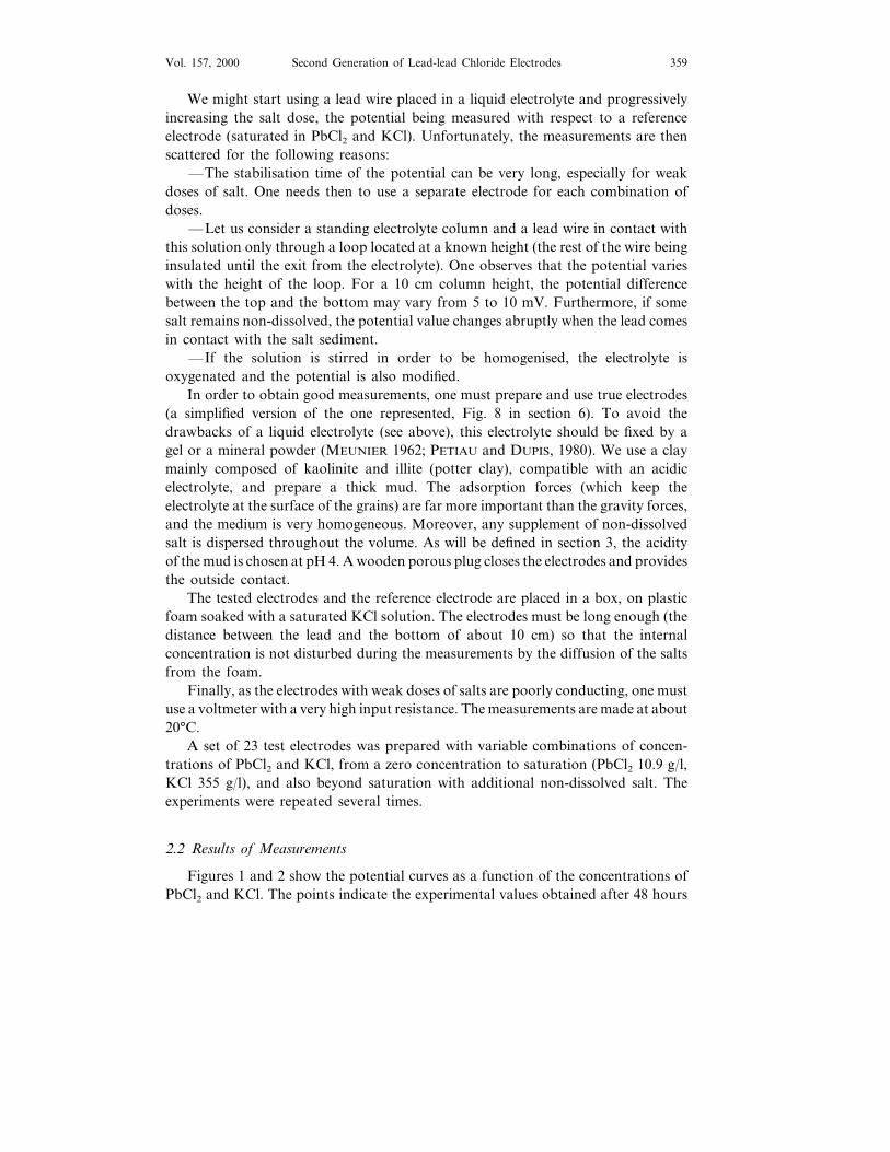
Second Generation of Lead-lead Chloride Electrodes 359Vol. 157, 2000
We might start using a lead wire placed in a liquid electrolyte and progressivelyincreasing the salt dose, the potential being measured with respect to a referenceelectrode (saturated in PbCl2 and KCl). Unfortunately, the measurements are thenscattered for the following reasons:
—The stabilisation time of the potential can be very long, especially for weakdoses of salt. One needs then to use a separate electrode for each combination ofdoses.
—Let us consider a standing electrolyte column and a lead wire in contact withthis solution only through a loop located at a known height (the rest of the wire beinginsulated until the exit from the electrolyte). One observes that the potential varieswith the height of the loop. For a 10 cm column height, the potential differencebetween the top and the bottom may vary from 5 to 10 mV. Furthermore, if somesalt remains non-dissolved, the potential value changes abruptly when the lead comesin contact with the salt sediment.
—If the solution is stirred in order to be homogenised, the electrolyte isoxygenated and the potential is also modified.
In order to obtain good measurements, one must prepare and use true electrodes(a simplified version of the one represented, Fig. 8 in section 6). To avoid thedrawbacks of a liquid electrolyte (see above), this electrolyte should be fixed by agel or a mineral powder (MEUNIER 1962; PETIAU and DUPIS, 1980). We use a claymainly composed of kaolinite and illite (potter clay), compatible with an acidicelectrolyte, and prepare a thick mud. The adsorption forces (which keep theelectrolyte at the surface of the grains) are far more important than the gravity forces,and the medium is very homogeneous. Moreover, any supplement of non-dissolvedsalt is dispersed throughout the volume. As will be defined in section 3, the acidityof the mud is chosen at pH 4. A wooden porous plug closes the electrodes and providesthe outside contact.
The tested electrodes and the reference electrode are placed in a box, on plasticfoam soaked with a saturated KCl solution. The electrodes must be long enough (thedistance between the lead and the bottom of about 10 cm) so that the internalconcentration is not disturbed during the measurements by the diffusion of the saltsfrom the foam.
Finally, as the electrodes with weak doses of salts are poorly conducting, one mustuse a voltmeter with a very high input resistance. The measurements are made at about20°C.
A set of 23 test electrodes was prepared with variable combinations of concen-trations of PbCl2 and KCl, from a zero concentration to saturation (PbCl2 10.9 g/l,KCl 355 g/l), and also beyond saturation with additional non-dissolved salt. Theexperiments were repeated several times.
2.2 Results of Measurements
Figures 1 and 2 show the potential curves as a function of the concentrations ofPbCl2 and KCl. The points indicate the experimental values obtained after 48 hours

Gilbert Petiau360 Pure appl. geophys.,
Figure 1Electrode potential as a function of PbCl2 concentrations for various concentrations of KCl, indicated
in g/l.
of stabilisation, and the curves are drawn using the method described thereafter.The obtained curves are very different from the ones, a priori expected, for secondkind electrodes.
Figure 1 clearly shows three different zones. In the first zone (PbCl2B0.15 g/l)the potential remains constant as PbCl2 concentration increases. Furthermore, thepotential is larger than that corresponding to the Pb+ + ions provided by PbCl2.One can conclude logically that there is a self-dissolution of the metal favoured bythe acidity of the medium (pH 4). In the second zone (PbCl2 varying from 0.15 g/lto 3–10 g/l) the potential increases with the provided quantity of PbCl2. Finally, inthe third zone (PbCl2\3–10 g/l), the potential again remains constant, aftersaturation is reached (for example, for KCl=0 we retrieve the known value of thesolubility of PbCl2 in water, which is about 10 g/l). When the KCl concentrationincreases, the potential decreases in the three zones, and not only in the third onewhere the saturation is reached, which should be emphasised.

Second Generation of Lead-lead Chloride Electrodes 361Vol. 157, 2000
Figure 2Electrode potential as a function of KCl concentrations for various concentrations of PbCl2, indicated
in g/l.
Considering that the solubility product Ks=1.7×10⁻⁵ for PbCl2 and theactivity coefficient is 0.58 for KCl at saturation (PAULING, 1963; HARNED andOWEN, 1958) we have:
[Cl−]= (355/74.6)×0.58=2.76 mol/l
and
[Pb+ +]=1.7×10⁻⁵/2.762=2.23×10−6 mol/l.
This corresponds to a value of 6.2×10⁻⁴ g/l for the PbCl2 concentration and thisis an upper bound because the real activity of [Pb+ +] can be weaker. For saturatedKCl, the potential should be independent of PbCl2 concentration beyond the valueof 6.2×10⁻⁴ g/l, whereas the measurements show that it depends on PbCl2 up toabout 3 g/l. To conclude, the computation using the solubility product of PbCl2cannot be used.
On the other hand, as shown in Figure 2, near the saturation in KCl, the slopeappears to decrease as [Cl−]4.3, while with PbCl2, the slope should be as [Cl−]2.
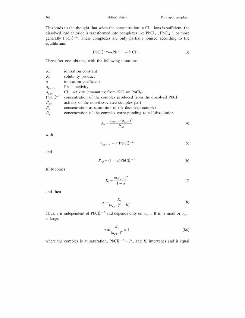
Gilbert Petiau362 Pure appl. geophys.,
This leads to the thought that when the concentration in Cl− ions is sufficient, thedissolved lead chloride is transformed into complexes like PbCl3−, PbCl4−2, or moregenerally PbClb2−b. These complexes are only partially ionised according to theequilibrium:
PbClb2−blPb+ + +b Cl−. (3)
Thereafter one obtains, with the following notations:
ionisation constantKi
Ks solubility producta ionisation coefficient
Pb++ activityaPb++
aCl− Cl− activity (emanating from KCl or PbCl2)PbClb2−b concentration of the complex produced from the dissolved PbCl2Pnd activity of the non-dissociated complex part
concentration at saturation of the dissolved complexPs
concentration of the complex corresponding to self-dissolutionPd
Ki=aPb+ +(aCl−)b
Pnd
(4)
with
aPb+ + =a PbClb2−b (5)
and
Pnd= (1−a)PbClb2−b (6)
Ki becomes
Ki=a(aCl−)b
1−a(7)
and then
a=Ki
(aCl−)b+Ki
. (8)
Thus, a is independent of PbClb2−b and depends only on aCl−. If Ki is small or aCl−
is large:
a:Ki
(aCl−)b�1 (8a)
where the complex is at saturation, PbClb2−b=Ps, and Ks intervenes and is equal

Second Generation of Lead-lead Chloride Electrodes 363Vol. 157, 2000
to aPb+ +(aCl−)b. Using (5), the obtained value for Ks is a Ps(aCl−)b and, using (8),Ps can be expressed as:
Ps=Ks
Ki
Ki+ (aCl−)b
(aCl−)b . (9)
If Ki is weak or if aCl− is large:
Ps:Ks/Ki. (9a)
Ps becomes a constant and then it does not depend on the supplied quantities ofPbCl2 or Cl−. Indeed, if aCl− increases, then aPb+ + (and also E from formula (1))decreases, however due to the variation of a, Cl− is eliminated and Ps remainsunchanged.
For lead electrodes, E0= −126 mV and the Nernst potential (1) is written:
E= −126+12.85 ln aPb+ +. (10)
The potential measured with respect to a hydrogen reference electrode is for asaturated PbCl2 and KCl electrode, E= −314 mV. The following quantities canthen be calculated. From (10) one obtains.
ln aPb+ + = (126−314)/12.85 aPb+ + =4.43×10⁻⁷ mol/l
Pb+ + dissolved=Ps=2.5/278 Ps=0.009 mol/l
then
a=4.43×10⁻⁷/0.009 a=4.9×10⁻⁵ (a is very weak).
The activity of Cl− provided by KCl (already computed) is:
aCl− = (355/74.6)×0.58 aCl− =2.76 mol/l
4.3 ions of Cl− are used in the complex for every Pb+ + ion, so:
4.3×0.009:0.04 mol/l.
The real activity of Cl− is 2.76–0.04=2.72 mol/l. One obtains, with (8a):
Ki=a aCl− =4.9×10−5×2.724.3 Ki=3.62×10⁻³
and with (9a)
Ks=ps×Ki=0.09×3.62×10−3 Ks=3.26×10⁻⁵.
Finally, using (5) and (8) we obtain for the expression of aPb+ +:
aPb+ + =Ki(PbClb2−b)Ki+ (aCl−)b . (11)
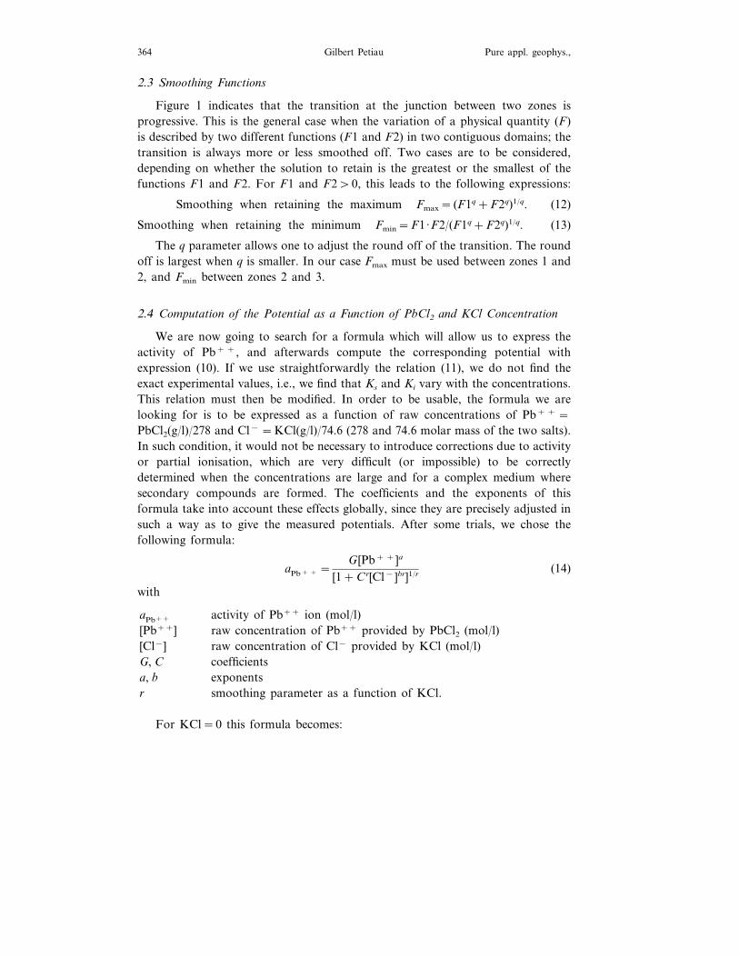
Gilbert Petiau364 Pure appl. geophys.,
2.3 Smoothing Functions
Figure 1 indicates that the transition at the junction between two zones isprogressive. This is the general case when the variation of a physical quantity (F)is described by two different functions (F1 and F2) in two contiguous domains; thetransition is always more or less smoothed off. Two cases are to be considered,depending on whether the solution to retain is the greatest or the smallest of thefunctions F1 and F2. For F1 and F2\0, this leads to the following expressions:
Smoothing when retaining the maximum Fmax= (F1q+F2q)1/q. (12)
Smoothing when retaining the minimum Fmin=F1·F2/(F1q+F2q)1/q. (13)
The q parameter allows one to adjust the round off of the transition. The roundoff is largest when q is smaller. In our case Fmax must be used between zones 1 and2, and Fmin between zones 2 and 3.
2.4 Computation of the Potential as a Function of PbCl2 and KCl Concentration
We are now going to search for a formula which will allow us to express theactivity of Pb+ +, and afterwards compute the corresponding potential withexpression (10). If we use straightforwardly the relation (11), we do not find theexact experimental values, i.e., we find that Ks and Ki vary with the concentrations.This relation must then be modified. In order to be usable, the formula we arelooking for is to be expressed as a function of raw concentrations of Pb+ + =PbCl2(g/l)/278 and Cl− =KCl(g/l)/74.6 (278 and 74.6 molar mass of the two salts).In such condition, it would not be necessary to introduce corrections due to activityor partial ionisation, which are very difficult (or impossible) to be correctlydetermined when the concentrations are large and for a complex medium wheresecondary compounds are formed. The coefficients and the exponents of thisformula take into account these effects globally, since they are precisely adjusted insuch a way as to give the measured potentials. After some trials, we chose thefollowing formula:
aPb+ + =G [Pb+ +]a
[1+Cr[Cl−]br]1/r (14)
with
activity of Pb++ ion (mol/l)aPb++
[Pb++] raw concentration of Pb++ provided by PbCl2 (mol/l)[Cl−] raw concentration of Cl− provided by KCl (mol/l)
coefficientsG, Cexponentsa, b
r smoothing parameter as a function of KCl.
For KCl=0 this formula becomes:

Second Generation of Lead-lead Chloride Electrodes 365Vol. 157, 2000
aPb+ + =G [Pb+ +]a. (14.1)
This is the expression corresponding to a first kind electrode, using only the metalsalt (zone 2 and curve KCl=0 of Fig. 1).
The validity domain of formula (14) is limited by self-dissolution (zone 1) andsaturation (zone 3). The limit corresponding to the self-dissolution (Pd) (between zones1 and 2 is independent of KCl, with Pd about 5.4×10⁻⁴ mol/l, corresponding to0.15 g/l of PbCl2. But the PbCl2 saturation limit (Ps), at the boundary between thezones 2 and 3 decreases at KCl increases, and must tend toward a limit when Cl−
becomes very large, as relation (9a) shows. We express this relation between Ps and[Cl−] by:
Ps=0.0154� 27.2+ [Cl−]
1+43.5[Cl−]�0.28
(15)
where KCl is very large (in fact beyond the Cl− provided by KCl at saturation), Ps
tends towards 5.4×10⁻³ mol/l, which corresponds to 1.5 g/l of PbCl2. However, thislimit cannot be fixed accurately because the greatest concentrations of Cl− are notreachable. The most important conclusion is that, with a self-dissolution correspondingto 0.15 g/l of PbCl2, zone 3 never reaches zone 1 and there is always a zone 2 wherethe potential remains a function of the provided PbCl2, whatever the Cl− concentrationis.
The parameters of the formula (14) have been adjusted by a systematic searchon a computer, in such a way as to reproduce the measured value. The smoothingparameter r as function of KCl is to be adjusted in each zone 1, 2, 3, (r1, r2, r3).We obtained the following values:
b qG r1 r2 r3C a4.6 4 0.280 0.2350.8 0.2270.0362 1.55
The G coefficient allows us to fix the computed values into the scale of standardpotentials. Thus we do obtain −324 mV for an electrode with saturated PbCl2 and KCl.
The computation steps are the following. For each dose of KCl we compute thevalues of aPb+ + first in zones 1 and 3 (where aPb+ + is independent of PbCl2), thenin zone 2 (where aPb+ + varies with PbCl2). The smoothing formulae are applied betweentwo successive zones (Fmax between 1 and 2, then Fmin between 2 and 3). Thereforethe method allows to compute aPb+ +, and the corresponding potential, withoutdiscontinuity, for all values of PbCl2 and KCl.
With NaCl (instead of KCl), and both salts NaCl and PbCl2 saturated, the electrodepotential is −297 mV. At saturation, the activity coefficients of KCl and NaCl arerespectively 0.58 and 0.99 (HANDBOOK OF CHEMISTRY AND PHYSICS, 1959; PAULING,1963). Activity of Cl− with KCl is 0.58×355/74.6=2.76 mol/l, and with NaCl0.99×361/58.5=6.2 mol/l. Therefore, the potential electrode with NaCl should beweaker than with KCl. However, the contrary is measured. One must then concludethat the presence of Na+ cations instead of K+ cations modifies the equilibrium ofthe formed Pb+ +, Cl− complexes.

Gilbert Petiau366 Pure appl. geophys.,
2.5 Conclusion
With KCl, the concentration of Pb+ + provided by PbCl2 is modified by theexponent a=0.8B1. This suggests that the activity decreases when the concentrationincreases.
Obtaining such a result, which is in very good agreement with the experimentalvalues, confirms that in the electrolyte, with a supplement of Cl− provided by KCl,Pb+ + ions form a mixture of complexes of PbClb2−b type. The number of Cl− ions(b) contained in the complex increases with the concentration in Cl−. At the limit,for a very high concentration, larger than that provided by KCl at saturation, themixture of complexes has an effect equivalent to a mean of 4.6 Cl− ions for one Pb+ +
ion. For the saturated KCl the equivalent effect is 4.3 Cl− ions for one Pb+ + ion.As the potential strongly varies as a function of the concentration of the salts,
it is necessary to keep the concentrations stable in order to have a stable potential.The best way to obtain this result is to use a saturated solution with additionalnon-dissolved salts for each of them (HEMPFLING, 1977). We will more thoroughlystudy this long-time stability in section 5.
3. The Electrodes Beha6iour as a Function of Internal pH
3.1 Aim of this Study
For our first electrodes the acid or basic reaction in the internal medium was notcontrolled; it was simply determined by the components of the electrolyte and theabsorbent material (plaster or clay):
KCl plaster pH 7.1 clay pH 6.6PbCl2pH 6.5 clay pH 6.1.plasterNaClPbCl2
It must be noted that such is the case for most types of electrodes; the pH is notadjusted, and is determined also by the used salts and the added absorbent materials(if any).
The pH parameter is very important and we will study here its influence on thepotential, on the noise, and on the temperature coefficient, in order to search the valuegiving the highest stability of the electrodes.
3.2 Preparation of the Electrodes and Methods of Determination of the pH Sensibility
A set of electrodes with 14 values of pH ranging from 0 to 10 has been first realised;afterwards more values of pH have been added to better define the parameters,changes where these changes are rapid. Two identical electrodes have been made foreach value of pH in order to measure the noise. As shown in the previous chapter,

Second Generation of Lead-lead Chloride Electrodes 367Vol. 157, 2000
in our experiments the electrolyte is saturated with an extra amount of non-dis-solved salts (PbCl2 and KCl), and powder clay is added to form thick mud. Foreach experiment a fraction of the water is replaced by a solution of hydrochloricacid or potassium hydroxide (HCl or KOH) in order to obtain the wanted pH. Dueto the presence of the clay, this pH takes a long time to stabilise and must bemeasured and adjusted a few days before using the mud in the electrodes.
As we need a time-span of about a month for the measurements, a PVC diskwith a narrow channel (f 1.5 mm and L 10 mm) is set up at the bottom of theelectrodes (like Fig. 8) to limit the exchanges with the outside. As the KCl issaturated inside the electrode, the electrical resistance of the channel is still weak(�400 V) while the protection is very efficient. The electrodes are set up verticallyon plastic foam soaked with a saturated KCl solution. All the potentials aremeasured with respect to an older (stabilised) reference electrode with an internalpH of 4. The whole device is placed in an oven at a temperature first fixed at 25°C.That allows us to measure two parameters as a function of pH: the potential (theaverage of the potentials of the two electrodes with the same pH), and the noise(the differences of potential for these two electrodes with the same pH). Then wemeasure the temperature coefficient of the electrodes by varying the oven tempera-ture. The potentials are measured once a day, spanning a month. These dailymeasuarements allow us to estimate the noise for a period (T) of two days.
For values of pH from 1 to 6, potential stabilises in 1 to 3 days, but for veryacid medium (pHB1) or basic ones (pH\7.5) the stabilisation is not yet reachedafter a month. This drift is due to the variation of pH with time. To take this intoaccount, the electrodes are dismantled after 30 days of measurements, and pH aremeasured once more. These final values are the ones which are used to draw thefollowing curves.
3.3 Results of Measurements for the KCl Electrodes
a. Potential. The first curve in Figure 3 shows the potential variation as afunction of pH, on the 30th day of the experiment. In the previous section we sawthat in an acid medium complexes with Cl− ions are formed. The H+ ions do notparticipate in the equilibrium described by formula (3) and this explains the veryweak variation of the potential with pH, from neutrality to pH 3. For pHB3, thepotential slowly increases with acidity until pH:1. For a very acid medium(pHB1) the concentration in Cl− ions from HCl is no more negligible comparedwith that due to KCl; the total concentration of Cl− increases and the potentialdecreases.
When the medium becomes basic, i.e., for pH larger than 7.3, the potentialsharply decreases. The nature of the electrode changes with the presence of OH−
ions, and a lead hydroxide is probably formed. The measurements made up to pH10 (not represented on Figure 3 in reason of the scale) show that the slope remains

Gilbert Petiau368 Pure appl. geophys.,
Figure 3Potential, noise and temperature coefficient of PbCl2, KCl electrodes as a function of pH.
constant and that the potential decreases by about −30 mV per unit of pH. Thisproves that is not Pb(OH)2 which intervenes: for an increase of one unit of pH, theOH− concentration is multiplied by 10, which would give a slope of−12.85 ln(102)= −59.2 mV.
We have carried out a few more experiments in basic media with variable dosesof KCl, which indicate that the potential also varies with the Cl− concentration.When the KCl concentration approaches saturation, the potential decreases by 34mV when KCl concentration is doubled. This demonstrates that there is a meanvalue of 34/12.85 ln 2=3.8 Cl− ions for one Pb+ + ion in the compound. Amixture of (PbClnOH)1−n complexes is then formed with an equivalent effect of amean value of 3.8 for n. These complexes are similar to those formed in an acidmedium, although here a Cl− ion is replaced by an OH− ion.
To conclude on the potential, to have the best potential stability, we mustchoose an acid medium with a pH varying from 3 to 6.5. Neutrality is to be
Second Generation of Lead-lead Chloride Electrodes 369Vol. 157, 2000
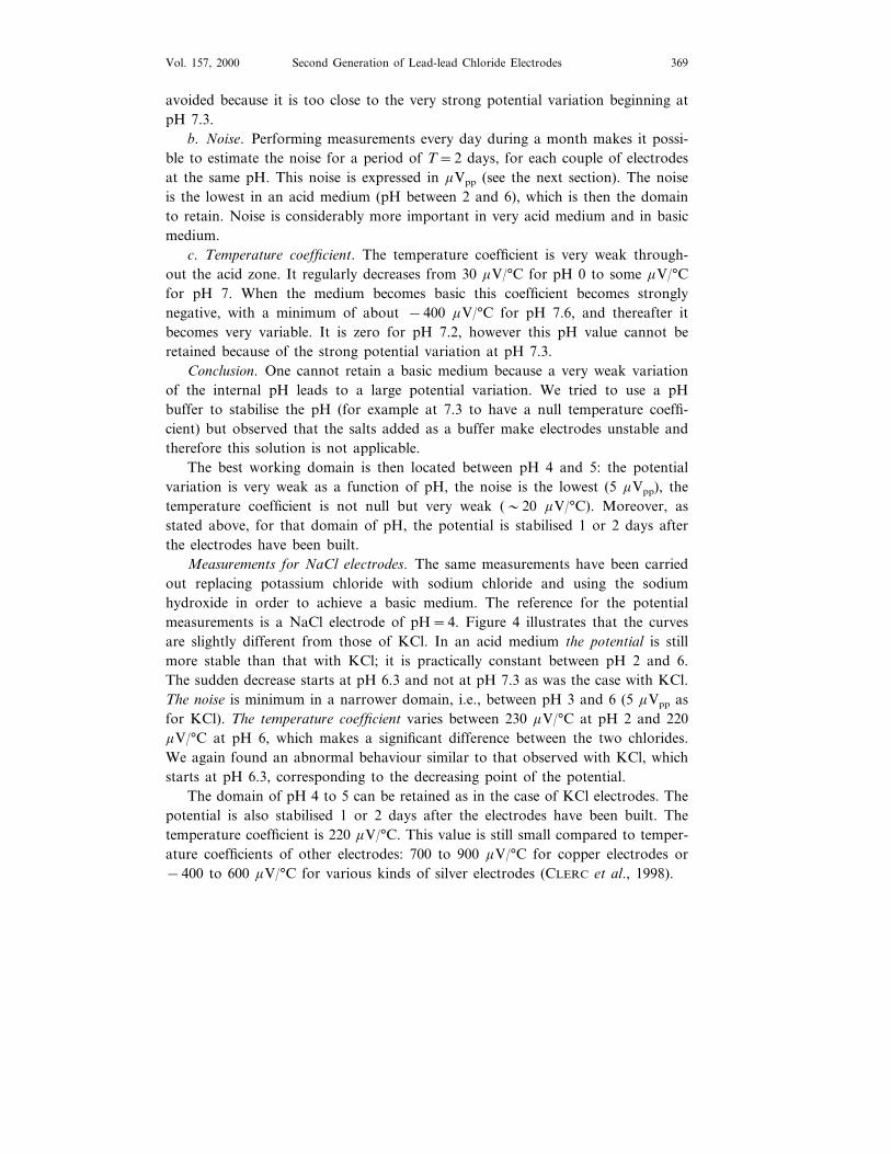
avoided because it is too close to the very strong potential variation beginning atpH 7.3.
b. Noise. Performing measurements every day during a month makes it possi-ble to estimate the noise for a period of T=2 days, for each couple of electrodesat the same pH. This noise is expressed in mVpp (see the next section). The noiseis the lowest in an acid medium (pH between 2 and 6), which is then the domainto retain. Noise is considerably more important in very acid medium and in basicmedium.
c. Temperature coefficient. The temperature coefficient is very weak through-out the acid zone. It regularly decreases from 30 mV/°C for pH 0 to some mV/°Cfor pH 7. When the medium becomes basic this coefficient becomes stronglynegative, with a minimum of about −400 mV/°C for pH 7.6, and thereafter itbecomes very variable. It is zero for pH 7.2, however this pH value cannot beretained because of the strong potential variation at pH 7.3.
Conclusion. One cannot retain a basic medium because a very weak variationof the internal pH leads to a large potential variation. We tried to use a pHbuffer to stabilise the pH (for example at 7.3 to have a null temperature coeffi-cient) but observed that the salts added as a buffer make electrodes unstable andtherefore this solution is not applicable.
The best working domain is then located between pH 4 and 5: the potentialvariation is very weak as a function of pH, the noise is the lowest (5 mVpp), thetemperature coefficient is not null but very weak (�20 mV/°C). Moreover, asstated above, for that domain of pH, the potential is stabilised 1 or 2 days afterthe electrodes have been built.
Measurements for NaCl electrodes. The same measurements have been carriedout replacing potassium chloride with sodium chloride and using the sodiumhydroxide in order to achieve a basic medium. The reference for the potentialmeasurements is a NaCl electrode of pH=4. Figure 4 illustrates that the curvesare slightly different from those of KCl. In an acid medium the potential is stillmore stable than that with KCl; it is practically constant between pH 2 and 6.The sudden decrease starts at pH 6.3 and not at pH 7.3 as was the case with KCl.The noise is minimum in a narrower domain, i.e., between pH 3 and 6 (5 mVpp asfor KCl). The temperature coefficient varies between 230 mV/°C at pH 2 and 220mV/°C at pH 6, which makes a significant difference between the two chlorides.We again found an abnormal behaviour similar to that observed with KCl, whichstarts at pH 6.3, corresponding to the decreasing point of the potential.
The domain of pH 4 to 5 can be retained as in the case of KCl electrodes. Thepotential is also stabilised 1 or 2 days after the electrodes have been built. Thetemperature coefficient is 220 mV/°C. This value is still small compared to temper-ature coefficients of other electrodes: 700 to 900 mV/°C for copper electrodes or−400 to 600 mV/°C for various kinds of silver electrodes (CLERC et al., 1998).

Gilbert Petiau370 Pure appl. geophys.,
Figure 4Potential, noise and temperature coefficient of PbCl2, NaCl electrodes as a function of pH.
4. Noise of Electrodes
Adopting the optimal conditions to build the electrodes (i.e., saturated solutionwith additional non-dissolved salts, pH 4 to 5, thick and homogeneous mud), thespectrum of the intrinsic noise of the electrodes has been measured.
The experiment was conducted in the same conditions as in the previous section.The entire experimental set is put into the oven at a constant temperature. Potentialdifferences between two electrodes are amplified and digitised with a samplingdepending on the studied periods range. The noise spectrum is determined by FFTor numerical filtering. We have tried hard to determine noise values for the long periods;these measurements are difficult because they are time-consuming (a minimum of 10to 20 times the considered period). However, the simultaneous recording of the noisefor several pairs of electrodes allows us to shorten this time span and to check thehomogeneity of the measurements.

Second Generation of Lead-lead Chloride Electrodes 371Vol. 157, 2000
The noise is relative to a pair of electrodes. It is not expressed in the form of anoise density (DF=1 Hz), but as the mean peak-to-peak value for DF=F (PETIAU
and DUPIS, 1980). This is very useful to directly compare the noise amplitude withthe amplitudes of the geophysical signals measured with the electrodes. The relationbetween the two noise expressions is:
Noise(Vpp, DF=F)=Noise(Vrms, DF=1 Hz)22F.
Figure 5 displays the results of the measurements. The noise for the electrodeswith plaster and NaCl (first generation, PETIAU and DUPIS, 1980) is also shown forcomparison (curve a). The second generation electrodes (curve b) present a muchreduced noise. Furthermore, the improvement of the amplifiers (LTC1052) allowsmeasurement of much weaker noise levels. For this second generation we have notfound significant differences between the KCl electrodes and the NaCl electrodes.We notice that a change of slope occurs around 10–30 minutes and the noiseincreases for longer periods.
The comparison between the two generations is interesting. For the firstgeneration, the experiment was carried out without temperature control, althoughthis cannot affect noise level within the period ranges studied at that time (B1000seconds). The composition of the internal medium was less homogeneous whenusing plaster than with clay-mud. Indeed, when preparing the electrodes, the plasterwas poured in a liquid state into the electrode tube and the non-dissolved saltscould more or less sediment before solidifying. The main explanation however isgiven by the study of the potential as a function of pH, in the previous section.Using NaCl and plaster, the pH was about 6.5, value confirmed by the
Figure 5Noise electrodes as a function of the period: (a) First generation with NaCl and plaster; (b) Second
generation with NaCl or KCl, pH 4 to 5 and clay mud.

Gilbert Petiau372 Pure appl. geophys.,
temperature coefficient of −40 mV/°C of these first generation electrodes. Theworking point was then in the very unfavourable domain in which the potentialstrongly varies as a function of pH (Fig. 3). Reducing pH in plaster is not possiblebecause it contains calcium carbonate, which decomposes when adding acid. Mudcan be used because it is compatible with an acidic medium.
5. Long-term Stability
5.1 Adaptation to the Applications
For usual magnetotelluric prospecting, which requires a few hours of record-ings, the long-time stability is not very important. In this case we especially look foran easy set-up and a quick stabilisation of the electrodes. To correctly obtain thediurnal variation and slower variations (within a few days), the recording time spanshould be a few weeks or even a few months. For other applications (evolution ofthe spontaneous polarisation or of the resistivity in a given site, search for signalsrelated to seismic activity), the electrodes must keep their stability for months oryears. As was noted, in order to keep a stable potential, it is at least necessary touse saturated solutions with additional non-dissolved salt.
5.2 Electrodes in Dry Ground
If the ground is dry it absorbs the internal solution of the electrode bycapillarity, and some salts deposit in places where the solution can evaporate. Atthe beginning this process takes place outside of the electrode and thereaftercontinues inside it, because air can penetrate the dried pores even if salts havedeposited. Thus, inside the electrode, the solution is saturated at the beginning andremains saturated. The potential changes only when there is no more liquidelectrolyte in contact with the lead wire. Experiments show that the potential thenincreases in the case of Pb-PbCl2 electrodes.
The electric resistance strongly increases during this dehydration, however as theamplifier which receives the signal of the electrodes has a very high inputimpedance, the measurement of this signal is not affected as long as the electroderesistance is not too large (about B100 kV).
5.3 Mitigation of the Dehydration Process
Experiments on hygroscopicity of salts in saturated solutions with additionalnon-dissolved salt (CLERC et al., 1998) demonstrate that there exists an equilibriumstate (no evaporation and no absorption of the air humidity) which depends on therelative humidity (RH) of the air, the nature of the salt and the temperature. For
Second Generation of Lead-lead Chloride Electrodes 373Vol. 157, 2000
example, at 25°C this equilibrium is reached for 88% RH for KCl and 82% RH forNaCl. Therefore NaCl keeps its water in a lightly dryer atmosphere and is thenslightly more hygroscopic than KCl.
Even for a dry near-surface ground, the relative humidity of the air remains(except for very particular cases) quite important at depth. To reduce the dehydra-tion, the electrodes must be grounded deep enough (if possible) to generate arelative humidity larger than the equilibrium value and, as seen above, it ispreferable to use NaCl electrodes. We note that the small cross-section channelused to limit salt exchanges is also useful to delay the dehydration of the electrode.The electrode must be placed in salted clay mud in order to guarantee a goodcontact with the ground. The mud volume to be used varies from about a litre fordamp ground to tens of litres for dry ground.
5.4 Electrodes in Damp Ground
On the contrary, if the ground is damp or saturated in water, diffusion of ionsbetween the electrodes and the ground tends to equilibrate the concentrations of thetwo media, and consequently to decrease the concentration in the electrode. As longas the non-dissolved salt exists, the solution remains saturated and the potential iskept constant. The study of this diffusion between two media at different concen-trations allows us to determine the time span during which the potential remainsconstant, and to look for the conditions to increase this time span.
5.5 Study of the Diffusion
a. Cylindrical electrode. The general phenomenon of diffusion is described, inthe case of diffusion of molecules or ions in solutions, by the first law of Fick:
dm/dt= −kS dC/dt (16)
m mass of dissolved saltcross section of the electrodeSdiffusion coefficientk
C concentration of dissolved saltt time.
Initially, we assume a linear variation of the concentration from the outside ofthe electrode to the front of dissaturation (Fig. 6). The different concentrations areexpressed in terms of the saturation concentration:
concentration at saturation (CS=1)CS
maximum concentration (CM\1 with non-dissolved salt)CM
Cm minimum concentration outside the electrode.

Gilbert Petiau374 Pure appl. geophys.,
Figure 6Diffusion in cylindrical electrode.
The front of dissaturation proceeds by dx during time dt. The correspondingsalt mass variation is the sum of two terms: the first one, illustrated by the hatchingtriangle of Figure 6, results from the linear variation of concentration; the secondis the mass coming from the non-dissolved salt in the volume S dx :
dm= − (CS−Cm) dx/2− (CM−CS) dx or dm= − (2CM−CS−Cm) dx/2.(17)
The expression of dm is negative because m has decreased in the volume understudy and m has been eliminated through the section at x=0. Applying the Fick’slaw (16) with dc/dt= (CS−Cm)/x, we obtain:
−2S dm/dt= (2CM−CS−Cm) dx/dt=2k(CS−Cm)/x. (18)
Finally integrating from x=0 to x=L (L distance from the metal to the outside ofthe electrode), the time of dissaturation (tD) is:
tD=(2CM−CS−Cm)
(CS−Cm)L2
4k. (19a)
The time of dissaturation is proportional to the square of the electrode length.In the absence of additional non-dissolved salt (CM=CS), tD becomes independentof the concentrations:
tD=L2/4k. (19b)
We have the same result if the concentration in the electrode varies from CS toCm because dm and dC/dx decrease proportionally to each other. Finally, if theconcentration in the electrode is equal to the external concentration, the formula(19a) is indeterminate, the system is in equilibrium, and there is no more diffusion.
As in fact the front of dissaturation slowly proceeds with time, the variation ofconcentration is not exactly linear in x. A more detailed study reveals that the curve
Second Generation of Lead-lead Chloride Electrodes 375Vol. 157, 2000
is slightly convex upwards, which increases the slope near the outside of theelectrode and decreases it near the front of dissaturation.
We look for a solution by numerical computation and a trial and errortechnique. First, we represent the concentration in the function of x by:
C=Cm+ (CS−Cm)[(x/x1)+F ] (20)
where x1 is the abscissa of the front of dissaturation and F is a corrective termadded to a linear variation. The constraints are the following: C=Cm for x=0 andC=CS for x=x1. This implies F=0 for x=0 and x=1. Second, we look for anexpression of F such that the Fick’s law is verified in the whole interval from x=0to x=x1 (x1 abscise of the dissaturation front). It results that the variation in x iswell fitted by a third degree polynomial. Consequently, for dimensional reasons,(k.t)1.5 is introduced into the denominator. We must also express the variation of Fin function of concentrations, which we will do through a term GF, whence:
F=GF(x x12−x3)/(K t)1.5. (21)
It has been determined that the following form of GF provides a goodrepresentation:
GF=0.034(2.2CM0.7−1.2CM
−0.7−CS)/(CS−Cm). (22)
When the front of dissaturation reaches the metal wire (x1=L), t is tD, thedissaturation time. TD is a priori written in the form:
tD=GTL2/k (23a)
and our search method produces for GT, which represents the variation of tD infunction of concentrations, the expression:
GT=0.082(25CM1.72−24CM−CS)0.58/(CS−Cm). (23b)
Example : Mud with KCl, CM=2 (2 saturations, i.e., 2×355 g/l) k=8.6×10⁻¹⁰
m2/s or 74.4 mm2/day and external concentration Cm=0
tD=0.0084 L2.
day mm
For a saturated medium without additional non-dissolved salts (CM=CS=1),TD is zero. Let us notice that this is not the case with the approximate formula(19a). Therefore, without additional non-dissolved salts, the electrode potentialchanges instantaneously as soon as the electrode makes contact with an externalmedium at a weaker concentration. However, if the electrode is long enough orprovided with a narrow channel, the variation of the potential is slow.
Therefore, a formula (19a) gives dissaturation time values too large when CM isweak. For CM=3, the difference between the results of (19a) and (23a) is still one

Gilbert Petiau376 Pure appl. geophys.,
of 10%. For CM larger the variation of the concentration as a function of x takesa linear trend, and the two expressions give identical values. Nonetheless, for thestandard concentrations (CMB3), formula (23a) must be used.
b. Electrode with a channel. Figure 7 displays the sketch of an electrode with achannel. L and l are the lengths of the electrode body and channel; S and s are thecross sections of the electrode body and channel, respectively. We can study thevery interesting case when s�S and the dissaturation is strongly limited by thechannel. At the junction between the channel and the electrode body, the concen-tration is close to saturation. The flow dm/dt in the channel is QC=ks(CS−Cm)/1.
The dissaturation time is the ratio of the mass of available salt in the electrodebody (beyond saturation) to the flow in the channel:
tD:(CM−CS)(CS−Cm)
SLlks
. (24)
As SL is the volume of the body and l/s=R/r (R is the electrode resistance,which depends mainly on the channel resistance, and r is the resistivity), it follows:
tD:(CM−CS)(CS−Cm)
VRkr
(25)
i.e.,
tD=A VR.
We conclude that the dissaturation time linearly depends on: 1) the store of salt,2) the electrode volume, 3) the internal resistance.
Let us note that the ions diffusion and the electrolyte conductance are linked tothe ions mobility; it is then logical to obtain TD proportional to R. In formula (25)the product kr is constant and R only varies with the channel size and the natureof the used internal medium.
Figure 7Diffusion in electrode with channel.

Second Generation of Lead-lead Chloride Electrodes 377Vol. 157, 2000
5.6 Diffusion Coefficients and Resisti6ity
The clay mud allows the time of dissaturation to increase by 1.9 relative to theliquid electrolyte along; and, using NaCl, we win a factor 1.5 relative to KCl. Ourmeasurements lead to the following diffusion coefficients and resistivities:
1.6×10⁻⁹k liquid NaCl 1.09×10⁻⁹ m2/sKCl– 94.2 mm2/day138––
8.6×10⁻¹⁰k mud NaCl 5.86×10⁻¹⁰ m2/sKCl– 50.6 mm2/day74.4––NaCl 0.129 Vmr mud KCl 0.088
5.7 Numerical Applications and Verifications
Let us consider clay mud with KCl, CM=2 (2 saturations, i.e., 2×355 g/l)k=74.4 mm2/day, r=88 Vmm, Cm=0 (tD minimum). Then
Electrode without channel Electrode with channel(25)(23a)
tD=0.0084 L2 tD=1.2×10⁻⁴ LD2 Rday mm day mm V
Application to four electrodes of the identical volume:
Electrode without channel Electrode with channelL (mm) 150 150 15050
27 272747D (mm)R (V) 30 500 10005
18 years 36 years6.3 monthstD 21 days
With a more important quantity of non-dissolved salt (CM\2), the dissatura-tion time is strongly increased. However, experiments on electrodes without channelshow that, from CM=5 the increase is smaller than the calculated ones, and amaximum is reached for CM=8. The change of the mud structure with the saltdissolution is certainly one of the causes of this discrepancy, because the mud thentends to become a liquid electrolyte. We point out that lead chloride must notdissaturate either. But with a concentration of 40 g/l (4 saturations, CM=4) thisdissaturation is not of vital concern.
Our dissaturation formulae have been verified in the laboratory by numerousexperiments in which we varied the length of the cylindrical electrodes, thedimensions of the electrodes with a channel, and the concentrations (CM). Theelectrodes we used had small dimensions in order to accomplish reasonable

Gilbert Petiau378 Pure appl. geophys.,
dissaturation times, from a few hours to a few months. Setting the base of theelectrodes into water and measuring regularly the potential to detect its increase atthe moment of dissaturation made the measurements. Other experiments have beenconducted in the ground for dissaturation times spanning a few months to two years.With variable ground conditions (for example damp but non-saturated) measuredvalues are sometimes larger than the calculated ones by 20 to 40%.
We have noted in the introduction that some ions, different from those used inthe electrode, can modify its potential. When these ions are present in the soil, theyenter the electrode and its potential is perturbed. This perturbation can take placelong before the dissaturation time calculated above, because the buffer effect of asaturated solution with additional non-dissolved salt does not exist. Of course therisk of perturbation depends on the soil composition. The channel is useful again toreduce the ions entry in the electrode.
5.8 Comparison with Other Solutions
One may also use electrodes with a reserve of liquid electrolyte as LESMES (1998)or SCHWARZ (1998). A slight flow through the porous ceramic is obtained owingto an air inlet in the electrode. Therefore the internal concentration remains con-stant, and furthermore this flow may improve the contact in a dry ground. Asthere is consumption of electrolyte, a reservoir or a filling system is necessary,which complicates the installation. It is difficult to maintain a regular flow, andsurveillance and interventions are necessary. On the other hand, if the ground issoaked, water can enter the electrode (this process is different from diffusion) andquickly perturbs its potential.
Without air inlet and with a weakly porous material contact, no flow occurs and,in a damp ground, diffusion intervenes. For example, the electrodes built by JUNGE
(1990) are composed of a FILLOUX’s (1987) Ag-AgCl electrode placed in a chamberfilled with a saturated KCl solution with additional non-dissolved salt. The ceramichas the same effect as the channel described above, in addition to ensuring contactwith the ground. As the concentration gradient is mainly located through this porousceramic, in HEMPFLING’s (1977) electrodes with three chambers, the effect of threewalls amounts to a slowdown of the dissaturation of the internal part. Thedissaturation time of this type of electrodes is therefore expected to be proportionalto the electrical resistance of the porous parts and to the quantity of the additionalnon-dissolved salt.
BOGORODSKY and BOGORODSKY (1995) describes an interesting device (that hehas used for a number of years). A Pb-PbCl2 electrode (useful length �8 cm) is placedat the bottom of a plastic vessel, 20- to 30-cm high, filled with a mud made of soilto which considerable salt has been added (NaCl). The whole is equivalent to a verybig electrode, containing substantial non-dissolved salt, and for which the distancebetween the electrode metal and the ground (the top of the vessel) is 30–40 cm. Thisallows obtaining a dissaturation time (formula (19a)) of several years.

Second Generation of Lead-lead Chloride Electrodes 379Vol. 157, 2000
The same advantage is obtained by MEUNIER (1995) using a Cu-CuSO4
electrode with the electrolyte fixed in clay. The combination of three cylindricalvessels placed upside down, allows him to increase the current distance between themetal and the outside of the electrode. With an external diameter of about 9 cmand a height of 30 cm, a dissaturation time exceeding one year is expected by theauthor (and is certainly considerably larger in reality).
Our solution with a channel allows us to obtain a very important dissaturationtime with an electrode of small volume (example ¥ 32, L 180 mm) and a quiteacceptable internal resistance (B1000 V). A porous plug placed behind the channel(Fig. 8) ensures a good contact with the ground. The two functions, limitation ofthe dissaturation and contact with the ground, are separated here. The low volumeof these electrodes permits an easy set-up after which no particular maintenance isnecessary.
6. Fabrication of the Electrodes
A sketch of electrodes planned for long-time measurements is given in Figure 8.The composition of the clay mud is:
KCl (or NaCl)Water PbCl2 Clay or KaolinHCl conc (33%)1 litre 680 g 720 g 40 g 1.65 kg3.7 cm3
Salts, clay or kaolin must be in powder. A purity of 99% for salts is sufficient. Itmust be noted that lead electrodes are very weakly sensitive to impurities, but thatsuch is not the case, for example, for silver electrodes.
The mud must be prepared a few days in advance; after these few days the doseof acid can be adjusted to obtain a pH of 4 to 5. The lead wire used (L=85 mm,F=1.6 mm) is a standard one. Numerous experiments show that a high purity ora larger size of the wire does not create better results. Nevertheless, the wire mustbe carefully cleaned with tissues impregnated with a solvent such astrichloroethylene or acetone.
The electrode is filled with mud. The piece through which the channel is piercedmust be correctly fitted on the tube to avoid leakage. With a 10-mm long channeland a 1.7-mm diameter, the internal electrical resistance of the electrode is 400 Vwith KCl, and the calculated dissaturation time is about 14 years. Finally, theelectrode is closed by a porous plug: glued ceramic or wood simply maintained byits natural expansion with moisture.
After manufacturing, the electrodes are stored in a box on a bed of plastic foamsoaked with a saturated KCl or NaCl solution (same salt as in the electrodes). Theirpotential is measured every day over one or two weeks with respect to a referenceelectrode. This reference can be one electrode of the current set or, better, an olderelectrode from a previous manufacturing. The scattering of potential values is(except for accident) smaller than or equal to 0.2 mV.

Gilbert Petiau380 Pure appl. geophys.,
Figure 8Electrode for long-term measurements.
Let us note that the ‘‘tube’’ electrode model described in 1980, easy to set upand recover, is always valid for measurements continuing a few hours to a day,with the following modifications: plaster is to be replaced by mud and lead wiremust be located at the top of the part filled with mud. Wood is the best solutionfor the porous plug. The channel is not necessary for these short durationmeasurements.

Second Generation of Lead-lead Chloride Electrodes 381Vol. 157, 2000
7. Conclusion
The variation of the electrode potential as a function of the concentration ofPbCl2 and KCl 1) has experimentally been determined; 2) has permitted to derivea calculation method of this potential; 3) has permitted to show that the chemicalequilibrium of the Pb-PbCl2 electrodes is due to the formation of a complexformed of Pb+ + and Cl− ions.
With an internal pH adjusted to 4 or 5, the stability of the potential isimproved and the noise decreased for KCl electrodes as NaCl electrodes.
The main advantage of the KCl electrodes is a very small temperature coeffi-cient. In the ground however, it resists dehydration less well than NaCl electrodesdo. Furthermore, KCl is a high quality food for plants. The presence of KCl inthe ground, at weak concentrations at the edge of the electrodes, favours thegrowth of roots and the local potential can be disturbed (PERRIER et al., 1997).As a consequence, if the electrodes are grounded at sufficient depths (about 1 m),the temperature variations are very weak; it is preferable to use NaCl electrodes.
The study of the salts diffusion has permitted to establish formulae for thecalculation of the dissaturation time. With a saturated electrolyte and additionalnon-dissolved salts, stabilised in a thick clay mud and using a channel of smallsection to limit exchanges with the outside, the dissaturation time can be consider-ably larger than ten years.
Our electrodes have a weak volume, are insensitive to the orientation andtherefore easy to set up. Afterwards they work maintenance-free. For example,these electrodes are successfully used in various geophysical domains: volcanosurvey (ZLOTNICKI and LE MOUEL, 1988), study of the long-term telluric varia-tion on a site (PERRIER et al., 1998), search of telluric signals related to earth-quakes (GRUSZOW, 1997), determination of the upper mantle resistivity(LEMONNIER et al., 1998) or magnetotelluric measurements (see FILLOUX et al.,1994).
Finally, the realisation of the electrodes can be adapted to the short durationof measurements (magnetotelluric, reference electrodes in laboratory). As diffusiontakes place only during the time of measurements, it is very weak. When theelectrodes are not in service they are stocked on foam soaked with a solution ofthe same composition as the internal electrolyte in order to prevent diffusion. Forthis short time utilisation of the electrode volume can be considerably reduced.
Acknowledgements
The author wishes to sincerely thank M. Mandea, S. Guilder, F. Perrier and J.L. Le Mouel for useful discussions. This is IPGP contribution 1640.

Gilbert Petiau382 Pure appl. geophys.,
REFERENCES
ATKINS, P. W., Physical Chemistry, 2nd ed. (Oxford University Press 1982).BARD, A. J., and FAULKNER, L. R., Electrochemical Methods, Fundamentals and Applications (John
Wiley and Sons, Inc., Texas University 1980).BOGORODSKY, V. M., and BOGORODSKY, M. M. (1995), Method and technical means for measuring
quasi-constant natural electric fields, Proceedings of the workshop electrodes Centre de RecherchesGeophysiques Garchy, 36–39.
CLERC, G., PETIAU, G., and PERRIER, F. (1998), The Garchy 1995–1996 Electrode Experiment TechnicalReport, edited by CEA.
FILLOUX, J., Instrumentation and experimental methods for oceanic studies. In Geomagnetism, Vol. 1 (ed.Jacobs, J. A.) (Academic Press, London 1987).
FILLOUX, J., CHAVE, A. G., TARITS, P., PETITT, R. A., MOELLER, H. H., DUBREULE, A., PETIAU, G.,and BANTEAU, L. (1994), Southeast Appalachians Experiment: Offshore Component, 12th WorkshopInduction Electromagnetique dans la Terre, Brest, France, 112.
GRUSZOW, S. (1997), Les signaux renifleurs des seismes Grecs, La Recherche 303, 28–31.HANDBOOK of CHEMISTRY and PHYSICS (Chemical Rubber Publishing Company, Cleveland Ohio 1959)HARNED, H. S., and OWEN, B. B., The Physcial Chemistry of Electrolytic Solutions, third ed. (Reinhold
Publishing Corporation, New York 1958).HEMPFLING, R. (1977), Beobachtung und Auswertung tagesperiodischer Variationen des erdelektrischen
Feldes in der Umgebung 6on Gottingen, Dissertation Math. Nat. Fak. Univ. Gottingen.JUNGE, A. (1990), A New Telluric KCl Probe Using Filloux’s AgAgCl Electrode, Pure appl. geophys. 134,
589–598.LEMONNIER, C., PERRIER, F., TARITS, P., ALEXANDRESCU, M., and PETIAU, G. (1998), Determination
of the Upper Mantle Electrical Conducti6ity, The 14th Workshop on Electromagnetic Induction in theEarth, Sinaia Romania, 115.
LESMES, D. (1998), in The Garchy 1995–1996 Electrode Experiment Technical Report, pp. 36–38.MEUNIER, J. (1962), Contribution a l’etude experimentale des problemes d’enregistrement electro-tel-
luriques et a l’amelioration des techniques de prospection, These 3eme cycle, Faculte des Sciences deParis, Laboratoire de Geophysique Appliquee.
MEUNIER, J. (1995), Diurnal earth currents with short lines and unpolarised copper-sulfate-kaolinelectrodes, Proceedings of the workshop electrodes Centre de Recherches Geophysiques Garchy,22–25.
PAULING, L., College Chemistry, 2nd ed. (Freeman W.A. and Co., San Francisco 1963).PERRIER, F., PETIAU, G., CLERC, G., BOGORODSKY, V., ERKUL, E., JOUNIAUX, L., LESMES, D.,
MACNAE, J., MEUNIER, J., MORGAN, D., NASCIMENTO, D., OETTINGER, G., SCHWARZ, G., TOH,H., VALIANT, M. J., WOZOFF, K., and YAZICI-CAKIN, O. (1997), A One-year Systematic Study ofElectrodes for Long-period Measurement of the Electric Field in Geophysical En6ironment, J. Geomag.Geoelec. 49, 1677–1696.
PERRIER, F., TRIQUE, M., LORNE, B., AVOUAC, J. P., HAUTOT, S., and TARITS, P. (1998), ElectricPotential Variations Associated with Lake Le6el Variations, Geophys. Res. Lett. 25, 1955–1958.
PETIAU, G., and DUPIS, A. (1980), Noise, Temperature Coefficient, and Long-time Stability of Electrodesfor Telluric Obser6ations, Geophys. Prospecting 28, 792–804.
SCHWARZ, G. (1998), in The Garchy 1995–1996 Electrode Experiment Technical Report, pp. 52–54.ZLOTNICKI, J., and LE MOUEL, J. L. (1988), Volcanomagnetic Effects Obser6ed on Piton de la Fournaise
Volcano (Reunion Island): 1985–1987, J. Geophys. Res. 93, 9157–9171.
(Received January 15, 1999, accepted June 7, 1999)