Embed Size (px)
Citation preview

PUBLICATION
SECOND-CLASS
21111
Radiotelephone LICENSE HANDBOOK by Edward M. Noll

Second-Class Radiotelephone License Handbook
by
Edward M. Noll
HOWARD W. SAMS 8( CO., INC.
THE BOBBS -MERRILL CO., INC. INDIANAPOLIS • KANSAS CITY • NEW YORK

FIFTH EDITION
FIRST PRINTING-1974
Copyright C) 1961, 1964, 1965, 1966, 1971, and 1974 by Howard W. Sams & Co., Inc., Indianapolis, Indiana 46268. Printed in the United States of America.
All rights reserved. Reproduction or use, without express per-mission, of editorial or pictorial content, in any manner, is pro-hibited. No patent liability is assumed with respect to the use of the information contained herein.
International Standard Book Number: 0-672-21111-4 Library of Congress Catalog Card Number: 74-79349

Preface
The major objective of Second-Class Radiotelephone License Hand-book, fifth edition, is to prepare the prospective license holder for tak-ing the required FCC examination. A second-class radiotelephone license requires a passing grade for Elements I, II, and III tests. This book contains the answers to the questions asked in the FCC Study Guide and Reference Material for Commercial Radio Operator Exami-nations. Much additional information is included in the introductory chapters. The extensive appendices are of assistance in understanding FCC Rules and Regulations and better preparing you for the FCC tests. The first chapter provides a thorough coverage of operator and sta-
tion licensing requirements. The various types of radio services are described. In Chapter 2 operating frequencies, propagation character-istics, and type of emission and modulation are detailed. Chapters 3 and 4 concentrate on the responsibilities of a second-class radiotele-phone license holder. In learning about test equipment and typical two-way radio commercial gear you will also be preparing yourself for employment in the field as well as preparing yourself well for the FCC tests.
Recently new changes in the broadcast radio services permit the em-ployment of the second-class radiotelephone license holder. Therefore an additional chapter has been added to this new edition. Chapter 5 provides an introduction to the broadcast services. Additionally, Ap-pendix VI covers the appropriate broadcast rules and regulations. The answers to Elements I and II Study Guide Questions are given
in Chapter 6. Chapters 7 through 14 do the same for the Element III questions. Questions and answers have been arranged for study in such form that you can progress logically from one topic to another. This arrangement permits you to uncover possible weaknesses in your li-cense preparations. Furthermore, each of the study guide chapters in-clude a self-examination and accompanying answers. There are two 100-question tests in Chapter 15 which will give you considerable ex-perience in preparing for the FCC-type examinations. Two queries often posed by persons studying for the license exami-
nation are: "What am I qualified to do, and what are my responsibili-ties as a license holder?" This handbook attempts to answer these im-portant questions as well as preparing you for the examination.
EDWARD M. NOLL


Contents
CHAPTER 1
OPERATOR AND STATION LICENSING 9 Introduction—Preparation for License Examination—Lower-Grade Li-censes—Fundamental Systems—Definitions of Station Assignments— Station Assignments and Licensing—Business Radio Service—Station License—Citizens Radio Service—Marine Radiotelephone—Technical Considerations—FCC Field Offices
CHAPTER 2
TRANSMISSION CHARACTERISTICS Frequencies and Operating Characteristics—Types of Emission and Modulation
CHAPTER 3
TEST EQUIPMENT AND METHODS Required Test Equipment—The Absorption Wavemeter—Tuning Meter —Grid-Dip Oscillator—Power Output—Commercial RF Power Meters— Frequency and Frequency-Drift Measurement—Commercial Frequency Meter—Frequency and Modulation Meter—Oscilloscope FM Deviation Meter—Commun ications Monitor
CHAPTER 4
TRANSMITTER TUNING AND ADJUSTMENT General Considerations—Circuit Description—Transmitter Adjustment —UHF Transceiver—High-Powered RF Amplifier—Sideband Trans-ceiver—Representative Circuits—Neutralization—Transmitter Trouble Localization—Modulation Checks—Oscilloscopic Modulation Display
41
56
86

CHAPTER 5
RADIO BROADCASTING 127 Introduction—Technical Considerations—The Operator's Responsibili-ties—Transmitter Metering—Tolerances—Station Requirements—FCC Rules and Regulations—Station Plans—Broadcast Transmitters—Major Units of Antenna Systems
CHAPTER 6
ELEMENTS I AND II BASIC LAW AND OPERATING PRACTICES . . . 155 Element I—Basic Law—Element II—Basic Operating Practice—Chapter 6 Self-Test
CHAPTER 7
ELEMENT III ALTERNATING AND DIRECT CURRENT Definitions and Units—Electronic Components—Circuits—Calculations —Chapter 7 Self-Test
CHAPTER 8
165
ELEMENT III TUBES AND TRANSISTORS 178 Electron Tubes—Transistors—Chapter 8 Self-Test
CHAPTER 9
ELMENT III POWER SOURCES 202 Rectifiers and Filters—Batteries—Motors and Generators—Chapter 9 Self-Test
CHAPTER 10
ELEMENT III AMPLIFIERS AND OSCILLATORS 215 Audio Amplifiers—Radio-Frequency Amplifiers—Oscillators—Chapter 10 Self-Test
CHAPTER 11
ELEMENT III AMPLITUDE-MODULATION SYSTEMS Transmitters—A-M Modulation—Single Sideband—Receivers—Chapter 11 Self-Test
243

CHAPTER 12
ELEMENT III FREQUENCY MODULATION 262 Modulation and Modulators—FM Maintenance—FM Receivers—Chapter 12 Self-Test
CHAPTER 13
ELEMENT III ANTENNAS AND LINES 283
Transmission Lines and Waveguides—Antennas—Propagation—Chapter 13 Self-Test
CHAPTER 14
ELEMENT III TEST EQUIPMENT, MEASUREMENTS, AND RADIO LAW. 299 Indicating Instruments—Measurements—Rules and Regulations—Sche-matic Questions—Chapter 14 Self-Test
CHAPTER 15
EXPERIENCE TESTS 326 Experience Test 1—Review Assistance—Experience Test II—Review Assistance
APPENDIX I
TWO-W AY RADIO ASSIGNMENTS: LAND, AVIATION, AND MARINE . 345
APPENDIX II
DEFINITIONS OF STATION ASSIGNMENTS FROM THE FCC RULES AND REGULATIONS
APPENDIX III
353
REFERENCE MATERIAL FOR ELEMENTS I AND II STUDY . . . . 361

APPENDIX IV
ADDITIONAL REFERENCE MATERIAL FOR ELEMENTS I AND II STUDY. 364
APPENDIX V
REFERENCE MATERIAL FOR ELEMENT III STUDY
APPENDIX VI
BROADCAST RULES AND REGULATIONS
ANSWERS TO TESTS
INDEX
373
390
432
443

CHAPTER 1
Operator and Station licensing
1-1. INTRODUCTION
Two-way radio systems, numbering in the millions are installed, adjusted, repaired, and operated by communications technicians having a first- or second-class radiotelephone license. Many of these radio units are operated only by persons with a lower grade of license and, in some cases, by nonlicensed persons under the supervision of the licensed operator of a base station. However, the installation, adjust-ment, and repair of two-way radio gear is handled by a technician who has at least a second-class radiotelephone license. In fact, this grade of license, or a higher grade, is a prerequisite for making any adjustments that influence the operating frequency, power input/output, or modu-lation level of the transmitter. The holder of a second-class radiotele-phone license can perform specified duties in radio broadcast stations. Detailed information about this new opportunity is given in Chapter 5 and Appendix VI. The purpose of this book is to assist a prospective license holder to
obtain a secon I-class radiotelephone license. Study the book com-pletely, not only the answers to the study guide questions. Remember that the study guide questions are only a guide to preparing for the examination. The actual FCC examinations are in the form of multiple-choice questions. These questions are not released and can be changed at will by the Federal Communications Commission. Nevertheless, if you can answer and understand your answers to the Study Guide Questions you should have no trouble passing the FCC examination. The study of the extensive supplementary information given in this book increases and firms your knowledge of appropriate two-way' radio equipment, broadcast installations and operating procedures. This ad-ditional information is of assistance in helping you pick out a correct answer to some of the more elusive FCC multiple-choice questions. The first four chapters of the book concentrate on the various two-
way radio services in a manner that helps you understand the responsi-bilities of a license holder. Typical two-way radio equipment is de-scribed. Most important, test equipment and test procedures are de-tailed. This lat:er information is particularly helpful in carrying out
9
10 SECOND-CLASS RADIOTELEPHONE LICENSE HANDBOOK
those adjustments which ensure compliance with the FCC technical standards.
In summary, the book is an aid in securing the license, disclosing to you the responsibility of such a license, and familiarizing you with the services you can render as a license holder. You can adjust and service or supervise the adjustment and servicing of a wide variety of radio stations. There are a few exceptions, but they are outside the realm of two-way radiophone. However, the second-class licensee is qualified to work as a duty operator in a-m and fm broadcast stations, for certain broadcast-station operations, and for operation and some servicing of low-power educational fm and tv stations, plus certain broadcast-relay facilities. The second-class radiotelephone license holder can also service land-
based and aircraft radar. By passing a supplementary radar examina-tion, he is also permitted to adjust and service marine radar equipment.
1-2. PREPARATION FOR LICENSE EXAMINATION
The second-class radiotelephone license holder, with respect to two-way radio systems, can operate, adjust, and maintain any licensed sta-tion in these radio services. Holders of a third-class radiotelephone li-cense can perform radio operating duties only, but must be familiar with radio law and basic operating procedures. It is not necessary for the holder of a restricted radiotelephone permit to pass an examina-tion. Quite often, however, he can perform operating duties only under the supervision of a person holding a higher-grade license. For these reasons, a technician entering the two-way radiocommunications field is advised to study for and obtain the second-class radiotelephone license so that his knowledge and technical skills can be used more fully in the radiocommunications field. The first step to take is to study for and pass the required FCC exam-
ination. The FCC examination for a second-class radiotelephone license involves Elements I, II, and III. Element I covers basic laws and it con-sists of twenty questions, each question with a 5-percent credit value. Element H has to do with operating practices. It consists of twenty questions, each with a 5-percent credit value. The twenty questions of Element II are subdivided so that a candidate may elect to answer either questions in the maritime field (M), or questions of a general nature (0). Element III is on the subject of basic radiotelephony. It consists of 100 questions, each with a 1-percent credit value. The pass-ing grade for each element is 75 percent. Study questions and answers for these elements are presented in Chapters 6 through 14 of this handbook. Again, a knowledge of these answers provides the back-ground needed to pass the license examination. None of the questions in the examination require an essay-type
answer. Most questions have multiple-choice answers. Element III is a mixture of multiple choice, and schematic completion and correc-tion. For multiple-choice questions the applicant must select only one answer. The letter preceding the answer the applicant considers correct is indicated by placing an appropriate mark in association with this
OPERATOR AND STATION LICENSING 11
letter on a separate answer sheet. A typical example question follows: Inductive reactance is measured in:
A. Farads B. Henrys C. Ohms D. Mhos E. Hertz
The correct answer is ohms; therefore, the letter C would be corre-spondingly marked on the answer sheet.
After you feel prepared to take the examination, you can request forms 756 and 756B from the District Office of the Federal Communi-cations Commission. The offices are listed at the end of this chapter. These application forms can be filled out prior to your trip to the dis-trict office. You will also receive an examination schedule so that you will know when to appear for the examination. The application, along with an examination fee, must be submitted prior to taking the examination.
After the license is obtained it must be properly posted. The original license of each station operator must be posted at the place where he is on duty except as otherwise provided in the rules governing the class of station concerned. If the license holder operates, adjusts, or services two or more stations, the license should be posted at one station and suitable verifications posted in the others. Verification forms are avail-able from the Federal Communications Commission. Most second-class radiotelephone license holders in the two-way communication business post the original license in their repair station. They also post a verifi-cation card in cther stations, or they have one on their person whenever operating or servicing any station under their control. The exact radio operator authority and posting requirements as they
appear in the FCC Rules and Regulations are as follows:
Sec. 13.61 Operating authority.
(f) Radiotelephone second-class operator license. Any station except:
(1) Stations transmitting telegraphy by any type of the Morse Code, or (2) Standard broadcast stations, or (3) International broadcast stations, or (4) Fm broadcast stations, or (5) Noncommercial educational fm broadcast stations with transmitter power
rating in excess of 1 kilowatt, or (6) Television broadcast stations licensed for commercial operation, or (7) Ship stations licensed to use telephony and power in excess of 100 watts for
communication with Class I-B coast stations. (8) At a ship radar station, the holder of this class of license may not supervise
or be responsible for the performance of any adjustments or tests during or coinci-dent with the installation, servicing or maintenance of the radar equipment while it is radiating energy unless he has satisfactorily completed a supplementary exami-nation qualifying him for that duty and received a ship radar endorsement on his license certifying to that fact: Provided, That nothing in this subparagraph shall be constructed to prevent persons holding licenses not so endorsed from making re-placements of fuses or of receiving-type tubes. The supplementary examination shall consist of:
(i) Written examination element: 8.

12 SECOND-CLASS RADIOTELEPHONE LICENSE HANDBOOK
(g) Radiotelephone third-class operator permit. Any station except: ( 1 ) Stations transmitting television, or (2) Stations transmitting telegraphy by any type of the Morse Code, or (3) Any of the various classes of broadcast stations other than noncommercial
educational fm broadcast stations using transmitters with power ratings of 10 watts or less, remote pickup broadcast stations and STL broadcast stations, or
(4) Class I-B coast stations at which the power in the antenna of the unmodu-lated carrier wave is authorized to exceed 250 watts, or
(5) Class II-B or Class III-B coast stations, other than those in Alaska, at which the power in the antenna of the unmodulated carrier wave is authorized to exceed 250 watts, or
(6) Ship stations or aircraft stations other than those at which the installation is used solely for telephony and at which the power in the antenna of the unmodu-lated carrier wave is not authorized to exceed 250 watts: Provided, That (1) such operator is prohibited from making any adjustments that may result in improper transmitter operation, and (2) the equipment is so designed that the stability of the frequencies of the transmitter is maintained by the trans-mitter itself within the limits of tolerance specified by the station license, and none of the operations necessary to be performed during the course of normal rendition of the service of the station may cause off-frequency operation or result in any un-authorized radiation, and (3) any needed adjustments of the transmitter that may affect the proper operation of the station are regularly made by or under the im-mediate supervision and responsibility of a person holding a first- or second-class commercial radio operator license, either radiotelephone or radiotelegraph as may be appropriate for the class of station involved (as determined by the scope of the authority of the respective licenses as set forth in paragraphs (a), (b), (e), and (f) of this section and Sec. 13.62), who shall be responsible for the proper func-tioning of the station equipment, and (4) in the cue of ship radiotelephone or air-craft radiotelephone stations when the power in the antenna of the unmodulated carrier wave is authorized to exceed 100 watts, any needed adjustments of the transmitter that may affect the proper operation of the station are made only by or under the immediate supervision and responsibility of an operator holding a first-or second-class radiotelegraph license, who shall be responsible for the proper func-tioning of the station equipment.
(h) Restricted radiotelephone operator permit. Any station except: ( 1) Stations transmitting television, or (2) Stations transmitting telegraphy by any type of the Morse Code, or (3) Any of the various classes of broadcast stations other than fm transistor and
booster, stations, or (4) Ship stations licensed to use telephony for communication with Class I coast
stations on frequencies between 4000 kHz and 30 MHz, or (5) Radio stations provided on board vessels for safety purposes pursuant to
statute or treaty, or (6) Coast stations, other than those in Alaska, while employing a frequency
below 30 MHz, or (7) Coast stations at which the power in the antenna of the unmodulated carrier
wave is authorized to exceed 250 watts; (8) At a ship radar station the holder of this class of license may not supervise
or be responsible for the performance of any adjustments or tests during or coinci-dent with the installation, servicing or maintenance of the radar equipment while it is radiating energy: Provided, That nothing in this subparagraph shall be con-strued to prevent any person holding such a license from making replacements of fuses or of receiving type tubes: Provided, That, with respect to any station which the holder of this class of license may operate, such operator is prohibited from making any adjustments that may result in improper transmitter operation, and the equipment is so designed that the stability of the frequencies of the transmitter is maintained by the transmitter itself within the limits of tolerance specified by the station license, and none of the opera-tions necessary to be performed during the course of normal rendition of the service of the station may cause off-frequency operation or result in any unauthorized radi-
OPERATOR AND STATION LICENSING 13
ation, and any needed adjustments of the transmitter that may affect the proper operation of the station are regularly made by or under the immediate supervision and responsibility of a person holding a first- or second-class commercial radio operator license, either radiotelephone or radiotelegraph, who shall be responsible for the proper functioning of the station equipment.
Sec. 13.62 Special privileges.
In addition to operating authority granted under Sec. 13.61, the following special privileges are granted the holders of commercial radio operator licenses:
(a) [Reserved] (b) The holder of any class of radiotelephone operator's license, whose license
authorizes him to operate a station while transmitting telephony, may operate the same station when transmitting on the same frequencies, any type of telegraphy under the following conditions:
(1) When transmitting telegraphy by automatic means for identification, for testing, or for actuating an automatic selective signaling device, or
(2) When properly serving as a relay station and for that purpose retransmitting by automatic means, solely on frequencies above 50 MHz, the signals of a radio-telegraph station, or
(3) When transmitting telegraphy as an identical part of a program intended to be received by the general public, either directly or through the intermediary of a relay station or stations.
(c) The holder of a commercial radio operator license of any class may operate broadcast stations under the following conditions:
(1) A duty operator in a standard broadcast station of any operating power, or one employing a directional antenna provided the station authorization does not require that the ratio of the antenna currents in the elements be held within a tolerance which is less than 5% or the relative phase of those currents within a tolerance which is less than 3*, an fm broadcast station of any authorized power, or a noncommercial educational fm broadcast station. Adjustments of transmitting equipment, except when under the immediate supervision of the radiotelephone first class operator is limited to the following:
(i) Those necessary to commence or terminate transmitter emissions as a rou-tine matter.
(ii) Those external adjustments that may be required as a result of variations of primary power supply.
(iii) Those external adjustments which may be necessary to ensure modulation within the limits required.
(iv) Those adfustments necessary to effect any changes in operating power which may be required by the station's instrument of authorization.
(y) Those necessary to change between nondirectional and directional or be-tween differing radiation patterns, provided that such changes require only activa-tion of switches and do not involve the manual tuning of the transmitter final amplifier or antenna phasor equipment. The switching equipment shall be so ar-ranged that the failure of any relay in the directional antenna to activate properly will cause the emissions of the station to terminate.
(2) A noncommercial educational fm broadcast station with authorized trans-mitter power output of more than 10 watts but not in excess of 1 kW: Provided, That adjustments of transmitting equipment by such operators, except under the immediate supervision of a radiotelephone first- or second-class operator, shall be limited to those adjustments set forth in subparagraph (I) (i), (ii), and (iii) of this paragraph.
(3) A noncommercial educational fm broadcast station with authorized trans-mitter power output of 10 watts or less: Provided, That adjustments of transmit-ting equipment by such operators, except under the immediate supervision of a radiotelephone first- or second-class operator or a radiotelegraph first- or second-class operator, shall be limited to those adjustments set forth in subpragraph (1), (i), (ii), and (iii; of this paragraph.
(4) Should the broadcast transmitting apparatus be observed to be operating in a manner inconsistent with the station's instrument of authorization and none of the adjustments specifically described under subparagraph (1), (2), or (3) of this paragraph are effective in bringing it into proper operation, an operator holding a

14 SECOND-CLASS RADIOTELEPHONE LICENSE HANDBOOK
lesser grade license than that which authorizes unlimited adjustment, with respect to the class of broadcast station involved, and not acting under the supervision of a person holding the higher grade license permitting such unlimited adjustment, shall terminate the station's emissions. ( 5) Except in the case of noncommercial educational fm broadcast stations with
authorized transmitter output power of 10 watts or less the special operating authority granted in this section with respect to broadcast stations is subject to the condition that there shall be in regular full-time employment at the station one or more operators of a class authorized to make or supervise all adjustments, whose primary duty shall be to effect and insure the proper functioning of the transmit-ting equipment. In the case of a noncommercial educational fm broadcast station with authorized transmitter output power of 10 watts or less such operator( s) shall nevertheless be available on call to make or supervise any needed adjustments.
(d) When an emergency action condition is declared, a person holding any class of radio operator license or permit who is authorized thereunder to perform limited operation of a standard broadcast station may make any adjustments neces-sary to effect operation in the emergency broadcast system in accordance with the station's National Defense Emergency Authorization: Provided, That the station's responsible first-class radiotelephone operator(s) s ) shall have previously instnicted such person in the adjustments to the transmitter which are necessary to accomplish operation in the Emergency Broadcast System.
Sec. 13.6 Operator license, posting of.
The original license of each station operator shall be posted at the place where he is on duty, except as otherwise provided in this part or in the rules governing the class of station concerned.
Sec. 13.73 Verification card. The holder of an operator license or permit of the diploma form ( as distinguished
from such document of the card form) may, by filing a properly executed applica-tion accompanied by his license or permit, obtain a verification card ( Form 758-F). This card may be carried on the person of the operator in lieu of the original license or permit when operating any station at which posting of an operator license is not required: Provided, That the license is readily accessible within a reasonable time for inspection upon demand by an authorized Government representative.
Sec. 13.74 Posting requirements for operator.
(a) Performing duties other than, or in addition to, service or maintenance, at two or more stations. The holder of any class of radio operator license or permit of the diploma form (as distinguished from the card form) who performs any radio operating duties, as contrasted with but not necessarily exclusive of service of maintenance duties, at two or more stations at which posting of license or permit is required shall post at one such station his operator license or permit and shall post at all other such stations a duly issued verified statement (Fonn 759).
(h) Performing service or maintenance duties at one or more stations. The holder of a radiotelephone or radiotelegraph first- or second-class radio operator license who performs, or supervises, and is responsible for service or maintenance work on any transmitter of any station for which a station license is required, shall post his license at the transmitter involved whenever the transmitter is in actual operation while service or maintenance work is being performed: Provided, That in lieu of posting his license, he may have on his person either his license or a verifi-cation card (Form 758-F): And provided further, That if he performs operating duties in addition to service or maintenance duties he shall, in lieu of complying with the foregoing provisions of this paragraph, comply with the posting require-ments applicable to persons performing such operating duties, as set forth in paragraph (a) of this section, and in the rules and regulations applicable to each service.
(c) One or more verified statements (Form 759), as necessary, will be issued to the holder of a restricted radiotelephone operator permit (card form license) who because of an operator license posting requirement at one station would not otherwise be able to comply with a license posting requirement or to carry his per-mit on his person when so required at another station or stations.

OPERATOR AND STATION LICENSING 15
1-3. LOWER-GRADE LICENSES
Many classes of two-way radio stations can be operated—but not serviced—by hclders of even lower license grades than the second-class radiotelephone license. Two such grades are the third class and the restricted radiotelephone permit. Questions in the third-class examina-tion are nontechnical and have to do with basic radio laws and operat-ing practices. Thus the applicant for this license must take only exami-nation Elements I and II. No examination is required for the restricted radiotelephone permit. Such license -holders may not adjust and service the radio station
equipment in any manner that could in any way possibly result in im-proper transmit.er operation. In general, for operating a radio station below 25 MHz. it is necessary that the person hold a commercial radio operator license or permit of any class. An unlicensed person, after being authorized to do so by the station licensee, may operate a mobile station during the course of normal rendering of service, while it is associated with and under the operational control of a base station of the same station licensee. For stations operating above 25 MHz, unli-censed persons may operate certain base and mobile stations after be-ing so authorized by the station licensee.
Certain a-m and fm broadcast stations may be operated by the holder of a third-class radiotelephone permit, provided he obtains a broadcast endorsement. The broadcast endorsement is obtained by passing an examination based on FCC element TX questions.
1-4. FUNDAMENTAL SYSTEMS
In the two-way radio services there are three major station classifica-tions—mobile, base, and fixed. A mobile station is one associated with a moving vehicle such as a truck, automobile, boat, or aircraft. A base station, often referred to as a land station, has a fixed position and is used for communicating with one or more mobile stations ( and on occa-sion, with other base or fixed dispatch stations.) The great majority of two-way radio systems come under the base-mobile classifications and usually include a single base station and one or more associated mobile stations. A fixed station is one in a permanent location used to communicate
with other fixed stations. This form of two-way radio is usually referred to as point-to-point communications. Normally, in such services, there are no facilities for communicating with mobile stations. Their princi-pal objective is to convey information between two or more fixed loca-tions. This differs from the base station, which also has a permanent position but is used for the purpose of communicating with mobile stations. The most common arrangements of two-way radio stations are shown
in Fig. 1-1. In the simplex arrangement of Fig. 1-1A, the base and mo-bile units operate on the same frequency (F1). A sequential "on-off" communications is established in which only one station can transmit at a given time, but can be heard by all other stations of the system. Each

16 SECOND-CLASS RADIOTELEPHONE LICENSE HANDBOOK
mobile station can hear both sides of a conversation between the base station and any mobile station. Likewise, communications can be estab-lished mobile-to-mobile when the stations are within range. Although not common, a simplex arrangement can also be used in a point-to-point radio system. The duplex arrangement of Fig. 1-1B is a common two-way radio
arrangement. The base station transmits on one frequency (F1), while
MOBILE
Fl
FI
I BASE I IMOBILE (A) Simplex.
F
F2
BASE MOBILE.
(B) Duplex.
FI
BASE
F2
MOBILE
POINT-TO-POINT
Fl
Fl
IFIXED I I FIXED I
FIXED TERMINAL
F
FIXED RELAY 2
F I F2
FIXED RELAY I
FIXED TERMINAL
F2 F
(C) Full duplex. (D) Full duplex, point-to-point.
Fig. 1.1. Two-way radio systems.
the mobile stations use a different frequency ( F2). In this arrangement the base station can communicate with all mobile stations, but the mobile stations cannot communicate directly with each other. Informa-tion to be conveyed between mobile units must be transmitted through the base station. Each mobile station receives only the base station signal. Although the duplex arrangement requires two transmitting frequen-
cies (one for the base station and one for the mobile units), it is usually more satisfactory. It is possible to exert better control over the mobile

OPERATOR AND STATION LICENSING 17
units, and each moble station is not confused by signals coming from other mobile stations (as with the simplex system). The duplex arrangement also uses an "on and off" method of trans-
mission. Quite often, frequency Fl is close to frequency F2. In fact, it is customary at each station to use the same antenna for transmitting and receiving. A relay, operating in conjunction with the transmit-receive switching of the station, changes the antenna between trans-mitter and receiver. It is not uncommon for other segments of the station equipment to be used in both the "receive" and "transmit" positions. A full duplex arrangement is shown in Fig. 1-1C. Operating frequen-
cies FI and F2 are well-separated; consequently, each station can transmit and receive at the same time. Each transmitter output is iso-lated and separated in frequency in order not to block the input of its companion receiver. With this arrangement, there can be simultaneous communications between the two stations as in line telephone conver-sations. If more than one mobile station is included, it will usually be on a different transmit frequency. The base station can use the same or a different frequency to establish communications with other mobile stations.
Full duplex is more common in point-to-point communication serv-ices than in mobile systems. In the typical arrangement of four stations shown in Fig. 1-1D, the transmit and receive frequencies of the various fixed stations are staggered, each station receiving on one frequency and transmitting on another. Highly directional antennas are employed, making it possible to establish duplex—and even full duplex—communi-cations with minimum interference between stations. Notice that relay station 1 transmits on Fl and receives on F2, and that relay station 2 transmits on F2 and receives on Fl. To permit the use of antenna sys-tems with the highly directional characteristics needed to prevent inter-ference, point-to-point stations are usually assigned frequencies which are in the microwave or upper half of the uhf spectrum.
1-5. DEFINITIONS OF STATION ASSIGNMENTS
There is a variety of station assignments for land, marine, and avia-tion communications. Some provide communications between land ve-hicles and their respective basic stations; others, between ships; and still others, between ship and fixed land stations. In the aviation serv-ices there are aircraft-to-ground stations and aircraft-to-aircraft com-munications. There are also special assignments that permit communi-cations between aircraft and seagoing vessels. Likewise, one or several small planes are often part of a two-way radio system that also includes land vehicles.
Because there are so many types of stations, it is important for the licensed radio operator to know the FCC terminology used in distin-guishing among them. (Refer to Appendixes I and II for definitions and various radio service classifications. Appendixes III and IV con-tain reference material for the study of Elements I and II; Appendix V. for the study of Element III.)
18 SECOND-CLASS RADIOTELEPHONE LICENSE HANDBOOK
1-6. STATION ASSIGNMENTS AND LICENSING
Each radio transmitter requires a station license. The transmitter operators do or do not require an operator's license, depending on the radio service they are associated with. For example, in most Maritime and Aviation Services it is necessary that the operator have a license. The broadcast operator requires a license. In fact, an operator's license is required for practically all radio services that operate below 25 MHz. In the Citizens Radio Service a station license is required, but the op-erator is not licensed. Many of the radio services above 25 MHz, in-cluding the Land Transportation, Public Safety, and Industrial Services do not require an operator's license. However, a distinction must be made between strictly operation and
equipment maintenance. In most cases, the lower-grade operator li-censes permit little else than the operation of those controls required in the normal handling of two-way radiocommunications. Adjustments or tests during or coincident with the construction, installation, servicing, or maintenance of a radio transmitter shall be made by or under the immediate supervision or responsibility of a person holding a first- or second-class commercial radio operator's license, either radiotelephone or radiotelegraph, as may be appropriate for the type of emission em-ployed. Such a licensee is responsible for the proper functioning of the radio-transmitter equipment. There are many point-to-point and mobile communications systems
that can be operated, installed, adjusted, and maintained by the second-class radiotelephone operator. In fact, practically all stations, except broadcast, radiotelegraph, and amateur stations, come under the au-thority of a second-class radiotelephone license holder. The second-class radiotelephone license holder is not authorized for
fixed stations using telephony and power in excess of 100 watts for communication with coastal telephone stations. In most instances, such stations also require radiotelegraph facilities, which come under the jurisdiction of a radiotelegraph license holder. Similarly, the second-class radiotelephone license holder is not authorized to operate certain aeronautical stations because they include radiotelegraph facilities. The most active two-way radio-frequency bands, which contain the
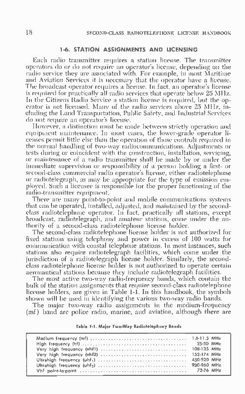
bulk of the station assignments that require second-class radiotelephone license holders, are given in Table 1-1. In this handbook, the symbols shown will be used in identifying the various two-way radio bands. The major two-way radio assignments in the medium-frequency
(mf) band are police radio, marine, and aviation, although there are
Table 1-1. Major Two-Way Radiotelephony Bands
Medium frequency (mf) 1 6-11 5 MHz High frequency (hf) 25-50 MHz Very high frequency (vhfl) 108-135 MHz Very high frequency (vhf2) 152-174 MHz Ultrahigh frequency (uhf i) 450 520 MHz Ultrahigh frequency (uhf2) 930-960 MHz Vhf point-to-point 72-76 MHz

OPERATOR AND STATION LICENSING 19
some point-to-point relay assignments and a very limited number of land-mobile allocations. Because of the great emphasis on small boats, an increasingly active portion of the spectrum between 1.6 and 3.5 MHz has been allocated to small-ship stations operating in coastal and inland waters. There are numerous aeronautical station assignments, largely for the benefit of air-carrier services (passenger and cargo). Many two-way radio aeronautical assignments, particularly for private air-craft and airdrome facilities, are made in the vhfl band. The upper portion of the hf spectrum is crowded with mobile assign-
ments. It includes not only the very active Citizens band, but a high percentage of the Public Service and Land Transportation Services as well. It is a very active portion of the frequency spectrum insofar as land mobile-radio equipment is concerned. Each transmitter must in some way be linked to a second-class radiotelephone license holder.
Similar assignments are made in the two vhf bands. The 72-76—MHz band has been allocated largely to operational fixed-station use. Point-to-point relay systems have allocations in this spectrum. In time, most point-to-point allocations and some of the systems now operating on this banal will use the superhigh frequency (shf) and the upper end of the uhf bands. A high degree of stability and freedom from inter-ference can be obtained more readily in the microwave spectrum. The second-class radtotelephone license holder will be able to assist in the development and use of these microwave relay assignments.
Aeronautical radio facilities dominate the vhfl spectrum. The assign-ments on the vhf2 spectrum are similar to those of the hf band. Land mobile-radio assignments are predominant. However, railroad radio and coastal radiomarine allocations are also available. The allocations on the uhf band are similar to those of the vhf and
hf bands. A number of fixed point-to-point allocations are becoming available, particularly at the high-frequency end of the uhf band. This band includes a Citizens-band spectrum and an impressive array of allocations for land vehicle, marine, and aviation facilities. Radio navi-gational aids (including radar) for aeronautical and marine services are served by uhf and higher microwave frequency assignments. Some mobile radio assignments are also made in the uhf television spectrum between 470-890 MHz. The informaton for the three general classifications of land, aviation,
and marine two-way radio assignments in Appendix I will give you an idea of the extensive use of radiocommunications equipment and the expansive avenues of growth possible. As you can see, your second-class radiotelephone license will open many transmitter doors for you.
In this chapter, three of the most active two-way radio services will be discussed in more detail; these are Business Radio, Citizens Radio and ship-to-shore radiotelephone. Permissible use, license require-ments, power, and frequency assignments are considered.
1-7. BUSINESS RADIO SERVICE
The Business Radio Service has grown considerably because any person engaged in a commercial activity is eligible for authorization.

20 SECOND-CLASS RADIOTELEPHONE LICENSE HANDBOOK
In addition, the service includes educational and philanthropic institu-tions, clergymen, ecclesiastical institutions, as well as hospitals, clinics, and medical associations. A variety of frequencies are available for assignment in the hf, vhfl, vhf2, uhf, and higher-frequency bands. As-signments predominantly are between 27-43 MHz, 150-158 MHz, and 461-470 MHz. When an application is made for an assignment in the Business Radio
Service, the application shall be accompanied by evidence of frequency coordination, except where the frequency requested and both immedi-ately adjacent frequencies are available for assignment in that service. If frequency-coordination information must be submitted, the appli-cant may submit a statement from a local frequency-advisory com-mittee recommending the specific frequency for assignment which, in the opinion of the committee, will result in the least amount of inter-ference to existing stations operating in the area. In lieu of the recom-mendation of the frequency-advisory committee, all stations operating in the area on the requested frequency within 75 miles of the proposed station, and all stations operating on any adjacent frequencies ( 15 kHz or less) and within 10 to 35 miles of the proposed station, must be noti-fied. The applicant shall submit a written and signed statement that all existing licensees within the frequency and mileage limits have been notified of the applicant's intention to request a particular frequency.
In no instance will an application be granted where the proposed station is located less than 10 miles from an adjacent-channel station 15 kHz removed. A statement is required from a frequency advisory committee recom-
mending the specified frequency which in the opinion of the committee will result in the least amount of interference to existing stations operat-ing in the particular area. The committee's recommendations may ap-propriately include comments on technical factors such as power, an-tenna height and gain, terrain, and other factors which may serve to mitigate any contemplated interference. The committee shall not rec-ommend any adjacent-channel frequency (15 kHz removed ) to existing stations which would result in a separation of less than 10 miles. The frequency advisory committee must be so organized that it is repre-sentative of all persons who are eligible for radio facilities in the service concerned in the area the committee purports to serve. The functions of such committees are purely advisory in character, and their recom-medations cannot be considered as binding upon either the applicant or the Commission, and must not contain statements which would imply that frequency advisory committees have any authority to grant or deny applications. Where the frequency or frequencies requested or assigned are within 15 kHz of a frequency which is avilable to another radio service, and are assignable only after coordination, the commit-tee's statement shall affirmatively show that coordination with a similar committee for the other service has been accomplished.
It is apparent that a second-class radiotelephone operator should know the Federal Communications Commission rules and regulations so that he might assist an applicant in submitting the proper applica-tion for station authorization.

OPERATOR AND STATION LICENSING 21
1-7-1. Technical Standards
Frequency—It is in the realm of the technical performance, in par-ticular, that responsibility is in the hands of the second-class radiotele-phone license holder. Of special concern are frequency and frequency stability, power input or output, and modulation level. Table 1-2 shows the frequency-stability requirements for operation in the Industrial Radio Services, which include business radio.
Table 1-2. Frequency-Stability Requirements for the Industrial Radio Services
Frequency range
Transmitter (input) power
Fixed and base stations Mobile stations
Over 300 watts
300 watts or less
Over 3 wafts
3 watts or less
MHz Percent Percent Percent Percent
Below 25 25 to 50 50 to 450 450 to 470 470 to 512 Above 950
0.005 .002 .0005 .00025 .00025
(*)
0.01 .002 .0005 .00025 .00025
(*)
0.01 .002 .0005 .0005 .0005
(*)
0.02 .005 .005 .0005 .0305
(")
*For microwave fixed equipment, see Sec. 91.111. For other equipment, tolerance will be specified in the station authorization.
Power—The power that may be used by a station in the Industrial Radio Services shall be no more than the minimum required for satis-factory technical operation commensurate with the size of the area to be served, and local conditions which affect radio reception and trans-mission. Except where the power which may be used on a designated frequency is specifically limited to a lower value, plate-power input to the final radio-frequency stage in excess of that shown in Table 1-3
Table 1-3. Plate-Power Input to the Final RF Stage
Frequency range
Maximum plate power input to the final radio frequency stage
(watts)
1.6-6.0 MHz 2000 25-100 MHz 500 100-216 MHz 600 220-470 MHz 600 470-512 MHz 1000 (erp)
will not be authorized. Under actual operation, the plate-power input to the final rf stage shall not exceed by more than 10% the plate-power input shown in the FCC radio-equipment list or the manufacturer's rated plate-power input for the particular transmitter listed on the authorization.
22 SECOND-CLASS RADIOTELEPHONE LICENSE HANDBOOK
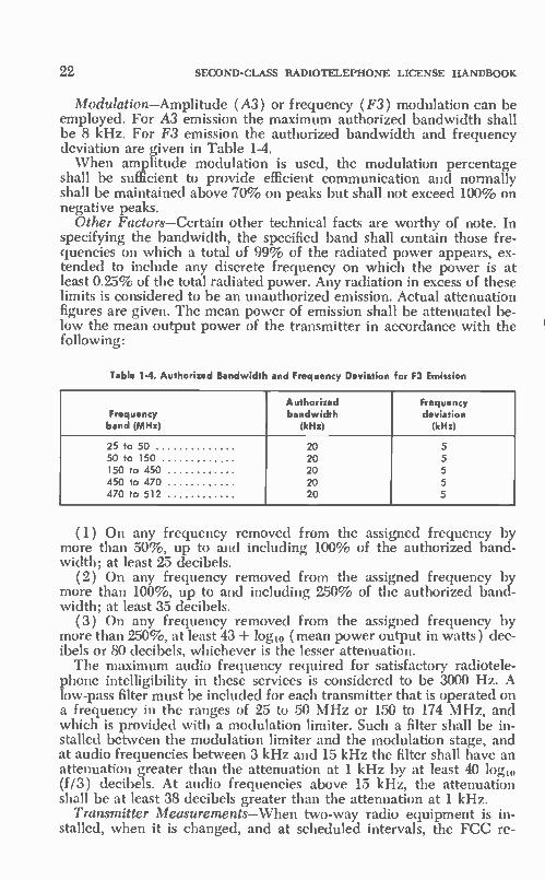
Modulation—Amplitude (A3) or frequency (F3) modulation can be employed. For A3 emission the maximum authorized bandwidth shall be 8 kHz. For F3 emission the authorized bandwidth and frequency deviation are given in Table 1-4. When amplitude modulation is used, the modulation percentage
shall be sufficient to provide efficient communication and normally shall be maintained above 70% on peaks but shall not exceed 100% on negative peaks.
Other Factors—Certain other technical facts are worthy of note. In specifying the bandwidth, the specified band shall contain those fre-quencies on which a total of 99% of the radiated power appears, ex-tended to include any discrete frequency on which the power is at least 0.25% of the total radiated power. Any radiation in excess of these limits is considered to be an unauthorized emission. Actual attenuation figures are given. The mean power of emission shall be attenuated be-low the mean output power of the transmitter in accordance with the following:
Table 1-4. Authorized Bandwidth and Frequency Deviation for F3 Emission
Frequency band (MHz)
Authorized bandwidth
(kHz)
Frequency deviation
(kHz)
25 to 50 20 5 50 to 150 20 5 150 to 450 20 5 450 to 470 20 5 470 to 512 20 5
(1) On any frequency removed from the assigned frequency by more than 50%, up to and including 100% of the authorized band-width; at least 25 decibels.
(2) On any frequency removed from the assigned frequency by more than 100%, up to and including 250% of the authorized band-width; at least 35 decibels.
(3) On any frequency removed from the assigned frequency by more than 250%, at least 43 + log10 (mean power output in watts ) dec-ibels or 80 decibels, whichever is the lesser attenuation. The maximum audio frequency required for satisfactory radiotele-
phone intelligibility in these services is considered to be 3000 Hz. A low-pass filter must be included for each transmitter that is operated on a frequency in thc ranges of 25 to 50 MHz or 150 to 174 MHz, and which is provided with a modulation limiter. Such a filter shall be in-stalled between the modulation limiter and the modulation stage, and at audio frequencies between 3 kHz and 15 kHz the filter shall have an attenuation greater than the attenuation at 1 kHz by at least 40 log10 (f/3) decibels. At audio frequencies above 15 kHz, the attenuation shall be at least 38 decibels greater than the attenuation at 1 kHz.
Transmitter Measurements—When two-way radio equipment is in-stalled, when it is changed, and at scheduled intervals, the FCC re-
OPERATOR AND STATION LICENSING 23
quires that transmitter measurements be made and recorded. Test equipment must be such that measurements can be made well within the established tolerance for the particular radio service. It is apparent then that the second-class radiotelephone license holder is in a position to provide a continuing technical service to the licensee of a two-way radio system. In fact, such a license holder can be involved w:th the initial planning and application for a station authorization, he can as-sume the responsibility for the installation plus the change and expan-sion activities of the system, and finally, he can perform the required FCC measurements. The actual FCC rules and regulations as they apply to the Industrial Radio Services, including business radio are as follows:
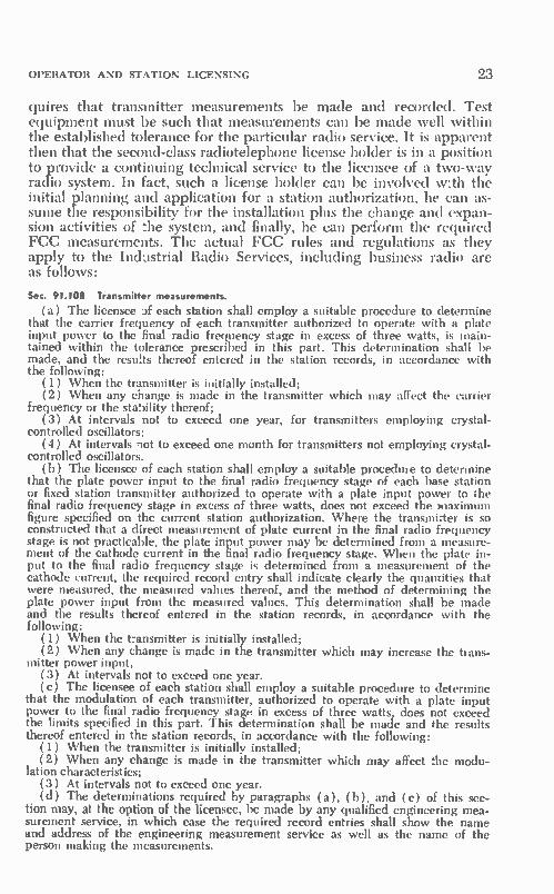
Sec. 91.108 Transmitter measurements.
(a) The licensee lf each station shall employ a suitable procedure to determine that the carrier frequency of each transmitter authorized to operate with a plate input power to the final radio frequency stage in excess of three watts, is main-tained within the tolerance prescribed in this part. This determination shall be made, and the reses thereof entered in the station records, in accordance with the following:
(1) When the transmitter is initially installed; (2) When any change is made in the transmitter which may affect the carrier
frequency or the stability thereof; (3) At intervals not to exceed one year, for transmitters employing crystal-
controlled oscillators; (4) At intervals not to exceed one month for transmitters not employing crystal-
controlled oscillators. (b) The licensee of each station shall employ a suitable procedure to determine
that the plate power input to the final radio frequency stage of each base station or fixed station transmitter authorized to operate with a plate input power to the final radio frequency stage in excess of three watts, does not exceed the maximum figure specified on the current station authorization. Where the transmitter is so constructed that a direct measurement of plate current in the final radio frequency stage is not practicable, the plate input power may be determined from a measure-ment of the cathode current in the final radio frequency stage. When the plate in-put to the final radio frequency stage is determined from a measurement of the cathode current, the required record entry shall indicate clearly the quantities that were measured, the measured values thereof, and the method of determining the plate power input from the measured values. This determination shall be made and the results thereof entered in the station records, in accordance with the following:
(1) When the transmitter is initially installed; (2) When any change is made in the transmitter which may increase the bans-
mitter power input, (3) At intervals not to exceed one year. (c) The licensee of each station shall employ a suitable procedure to determine
that the modulation of each transmitter, authorized to operate with a plate input power to the final radio frequency stage in excess of three watts, does not exceed the limits specified in this part. This determination shall be made and the results thereof entered in the station records, in accordance with the following:
(1) When the transmitter is initially installed; (2) When any change is made in the transmitter which may affect the modu-
lation characteristics; (3) At intervals not to exceed one year. (d) The determinations required by paragraphs (a), (b), and (c) of this sec-
tion may, at the option of the licensee, be made by any qualified engineering mea-surement service, in which case the required record entries shall show the name and address of the engineering measurement service as well as the name of the person making the measurements.

24 SECOND-CLASS RADIOTELEPHONE LICENSE HANDBOOK
(e) In the case of mobile transmitters, the determinations required by para-graphs (a) and (c) of this section may be made at a test or service bench: Pro-v:ded, That the measurements are made under load conditions equivalent to actual operating conditions: And provided further, That after installation in the mobile unit the transmitter is given a routine check to determine that it is capable of being received satisfactorily by an appropriate receiver.
1-8. STATION LICENSE
Radio transmitters in the two-way radio services may not be oper-ated without a station license. Such authorization is granted by the FCC. The necessary application form can be requested from the FCC in Washington, D.C., or from their district offices. The second-class radiotelephone license holder should be familiar
with the rules and procedures for obtaining such a station license, and he should be prepared to help the potential user to select the service most appropriate for his particular industrial, commercial, or profes-sional needs. He can also assist the user in making a wise selection of equipment and choice of frequency for the communication to be handled. Finally, he can lend a hand in completing the application and provide the necessary guidance until the system is in operation. The second-class radiotelephone license holder who can follow through from the initial planning to its culmination will be in the most advan-tageous position to attract new customers and users. He will also make himself rather indispensible in the maintenance and expansion of the present system.
Ile must know what category a potential user falls into with regard to the various two-way radio services. (These categories are presented in this chapter and Appendix I.) Complete information can be obtained from the respective FCC Volumes. A sample license-application form (FCC Form 400) is shown in
Fig. 1-2. It is this form that must be completed when applying for a station authorization in various radio services, including Business Radio. The meanings of specific items are as follows: Item 1 (c) refers to the type of emission. For example, 20F3 refers
to the use of frequency modulation with an assigned bandwidth of 20 kHz. Item 1 ( d) is the maximum input power.
Items 2 and 3 are self-explanatory. They include the transmitter ad-dress and the location of the transmitter control points. (The two may or may not be the same.)
Item 4 applies to all mobile stations, and to base and fixed stations at temporary locations. Describe as accurately as possible the area in which the stations or units of the stations normally will be operated. Antenna structure is covered in item 5 and includes the height of the antenna applied for in this application to its highest point above the ground level and the height of the antenna structure itself (building, tower, etc.), plus information concerning the elevation above mean sea level of the ground at the antenna location. The radio license service for which you are making application and
the class of stations are covered in item 6. Item 7 asks for individual and business addresses.

OPERATOR AND STATION LICENSING 25
The facts requested in 8 through 12 are obvious. Item 11 refers to the continuous sharing of radio facilities, such as to provide service to some of your mobile units installed in vehicles belonging to other per-sons separately engaged in transportation activities who are not licens-ees. Information must be given as to whether this communication serv-ice will be rendered without charge or on a nonprofit cost-sharing basis. Detailed information can be obtained from the rules and regulations of the appropriate radio service. Item 13 asks for a system diagram of the proposed radio system in-
cluding fixed or mobile systems involving two or more stations. Indi-cate the relative location of principal cities and towns and show the relative location of each existing and/or proposed station. Additional information is given in item 14 if the transmitter is not on the commis-sion's radio equipment list.
Item 15 verifies your eligibility and must include a general descrip-tion of your business or activities and how the radio system is to be employed in this activity. Include any information that will aid in the eligibility determination. In items 17 and 18 complete information is given with regard to antenna structure and use.
In some services, the FCC grants the station license immediately; in others, a construction permit is granted first. Final license is then granted after the station has been constructed and placed in operation, in compliance with technical standards of performance. The local FCC District Office must be notified when construction is completed and before tests are started. The main station license is posted at a fixed or base station location.
Separate transmitter-identification cards should be filled in and at-tached to each mobile transmitter ( Fig. 1-3).
It is the responsibility of the second-class radiotelephone license holder to keep an eye on the expiration date of the various transmitters with which he is concerned. He should take the necessary steps to re-new all licenses within two months before they expire.
1-9. CITIZENS RADIO SERVICE The Citizens Radio Service has had a phenomenal growth as attested
by the more than a million transmitters now in operation. Segments of the frequency spectrum have been set aside in the Citizens Radio Serv-ice to provide for a private short-distance radiocommunications service for the business or personal activities of licensees, for radio signaling, and for the control of remote objects or devices by means of radio. Any citizen of the United States who is 18 or more years of age (or 12 years for a Class-C station) may obtain a station license if his application meets the requirements of the service. Partnerships, associations, trusts, or corporations meeting the requirements, including any state, terri-torial, or local governmental entity, or any service organization or asso-ciation, including civil defense, may be licensed. The classes of CB stations are:
Class-A station: A station in the Citizens Radio Service licensed to be operated on an assigned frequency in the 460- to 470-MHz band and with a transmitter output power of not more than 50 watts.

*Owe
s y
*et
«6!a
FCC in, III
Fed's"», Commonicationt Cornrnis.ion
Soren Approved lodge, • No. 02.50132
MHZ
e,
0,1,er
COMMISSION MIS COPY
tit( iput
Wont
SO NOT WRITE IN TOUS BLOCK
Coll S on Fie Na
Arodnna painting and lighting tpec.I.COltOns.
SpeCel Condition,.
liai Stow No of mob( • on, .n ecnn 0, ,o,,0•••ne
ceheoe.oes tend ...hick. ni.crah
pog.4 hand co.iied
Thi, authorization isflecti••
and will axpir• 3.00 AM EST
and ',Mont na fiethsir conditions os set forth on re.•rs• side. If the seohon aoho.,,ed har..1 . npl placed in ope/ohon ...thin .01 month. thin Wheat:IMO biecocn•s involid and must b• rrrrr ned to the Comm,ssion for cancellation unleil on eioen•on of completion dole hos Selo ourhorled.
F•d•rol Comm•Acohons Commission
Sect•tary
L.,or.•• 61 re n ,•àed
Nurnett 0,1 V..' (0 , 0,6e• (mkt:0(0n 0,
C.. County Slope
lo,,p.d• o
n
iic 0, on ,enno It 1210nNnno lupy0r1(ng 100,(e
b. U....Jr On 0, giu debO,. rn•on sea ,e.el antenna
6( N lRd S
le) Clot, at slofien
one E Mob.le

-.111
Asyor wh om Ei CorporahonD Goyernmentol Enwy
'Po•ahon o, Iren, on on,n,o,00,,o, o„0,„„.„
outho•rear a, Li
, r partnws an alien' a We
lbroIor mod.. ohun, oow modrfootron proposed
person o ..... • • ve, N.(11
we rod,. waummII en 11
answe• gme nor, e
sr, •
. -CI urer
ron7 • If not We owner of ib. 'ado erourpmtwe PP' P g
under ...Yoh ...or wn be e•enood ro We son, monnw at .1 Wo egurprnent
were owned by rho PPProdn''
vJ -El
1Y...cooed Oar un •o 11 Low pu s or cornmunrcolron tall sagnsl
LI -CI
s 'Rod,
hewn,/ and .•• • . ..e I
"
I •• ry e
to .nrInsr•e( ore cam dewed woler.01 •er .....'ai'oo, ond all ib. erh•pros ore o enoterrol port ,•-•-• • a, ceehhes fly r he hos o currwo copy or We Commonon 1 Rules goywnrng W. pad, sot,. oy biro)
1hu •11̀ . 1 aY .9 '9.1 Me •egurWory power or the Unrred SIO191 because of lb. proy.out we of 1h• some. whelher by
yre ••. e & • •• yrd ••.• ro w• bus , al rn Soo...4.4e and bohor and amt made ••• good la w
• e p ny ws zed /co any owe ,
y., r] Nofl
17 II onrenna ..11 be wounlod on on e•ohng onrenna snucru•e. G..• ,orn• of Ircensee rys•ng W., ornlyrre. ho roll sin ond 'odor sew At ond We cyrren owner,
Ond Irghhng specrIrcohon rerwood by We Commrtyron ror W.s on 1enno snuthols
131 Il yo,,, proposed omenno oIl •ncr•ow ill. hofe, of ev.,019 snort., heooro oto••
ground or We Irp or 1h• proposed omenno snuchr••
IS ,,. wag tho omenno eaend 0'0 1h00 a We,
Wo g•ound. or wore Wan 20 roe also.. We noturol Wennoron or wohng mow
rnode f.fufftft• fonner h.,, an omen,' Or w• turej on whoh rt ry mounIedt
If 'Yes . onsww 101. Irl 101 'rot NoD and 1•1
(b) G••• h•rght obove groond for each component or the grown. slructoro
Idn'wn.• P.W. Iona, wa1er lower. most burldrng. chrwney, etc. or corn. b•notron al Weser.
Doran. ond doochon moor's,. ronwo y of
meows, carryon londrno onto. bd) Na.,. of londrng wea
ler Hat nor ,e or we c •oorned c••••snuchan o1 we ourenon sun hert been clod syroh oh• F
If'ow' sts•• nhen ono we nom• undw nhols ro nay Mod one/ 11, FAA •• gran& ono• whore •1 wos hIed Uso some on Wo row,. of ihrs pogo
It.
v., Iij No 11
00 NOT WHITE IN THIS BLOCK SIGNATURE
DATE I Dergnate apptopnale ['ass, hcar,on beloved
NYE Y.,6f P (JF
INC ""jAl E] E :.: PRL:Y=:11P E I'D'RZ:f:ri'Z ' IC NTEIJ 'ASN'I':?9PC'il;rcte
1 WILLFUL FALSE VAILMENTS MADE ON THIS FORM ARE PUNISHABLE BY FINE AND IMPRISONMENT. US CODE. 111LE IB SECTION 1001
OF r • ires1 OF
GC• ,.t.NMÉNIAL ENIITY
IOVERI

28 SECOND-CLASS RADIOTELEPHONE LICENSE HANDBOOK
o UNITED STATES OF AMERICA FCC Form 452-C
FEDERAL COMMUNICATIONS COMMISSION (March 1960)
TRANSMITTER IDENTIFICATION CARD
1. Station call sign:
2. Name and Address of Perminee or Licensee:
Fig. 14. Transmitter identification card.
Class-C station. A station in the Citizens Radio Service licensed to be operated on an authorized frequency in the 26.96- to 27.23-MHz band, or on the frequency 27.255 MHz, for the control of remote ob-jects or devices by radio, or for the remote actuation of devices which are used solely as a means of attracting attention, or on an authorized frequency in the 72- to 76-MHz band for the radio control of models used for hobby purposes only.
Class-D station. A station in the Citizens Radio Service licensed to be operated for radiotelephony, only, on an authorized frequency in the 26.96- to 27.23-MHz band and on the frequency 27.255 MHz. A station license is required; no operator's license is required. How-
ever, a commercial radio operator license of the proper class (minimum second-class radiotelephone license) is required for adjustments to any Citizens radio transmitter during installation, testing, or servicing, that may cause the transmitter to operate off-frequency or in a manner which may in other ways violate the rules. This regulation emphasizes that almost all repairs on Citizens band equipment should be made by the holder of a first- or second-class commercial license, either radio-telegraph or radiotelephone. The second-class radiotelephone license holder should have an understanding of the legal applications for CB equipment so he can properly guide a prospective customer or user.
95.83 Prohibited uses.
( a) A Citizens radio station shall not be used: (1) For engaging in radio communications as a hobby or diversion, i.e., operat-
ing the radio station as an activity in and of itself. NOTE: The following are typical, but not all inclusive, examples of the types of
communications evidencing a use of Citizens radio as a hobby or diversion which are prohibited under this rule: "You want to give me your handle and I'll ship you out a card the first thing in
the morning;" or "Give me your 10-20 so I can ship you some wallpaper." (Com-munications to other licensees for the purpose of exchanging so-called "QSL" cards. )
"I'm just checking to see who is on the air." "Just calling to see if you can hear me. I'm at Main and Broadway."

OPERATOR AND STATION LICENSING 29
"Just heard your call sign and thought I'd like to get acquainted;" or "Just pass-ing through and heard your call sign so I thought I'd give you a shout."
"Just sitting here copying the mail and thought I'd give you a call to see how you were doing." (Referring to an intent to communicate based solely on hearing an-other person engaged in the use of his radio.) "My 10-20 is Main and Broad Streets. Thought I'd call so I can see how well this
new rig is getting out." "Got a new mike on this rig and thought I'd give you a call to find out how my
modulation is." "Just thought I would give you a shout and let you know I am still around.
Thanks for coming back." "Clear with Venezuela. Just thought I'd let you know I was copying you up
here." "Thought I'd give you a shout and see if you knew where the unmodulated car-
rier was coming from." "just thought I'd give you a call to find out how the skip is coming in over at
your location. " "Co ahead breaker. What kind of a rig are you using? Come back with your
10-20." (2) For any purpose, or in connection with any activity, which is contrary to
Federal, State, or local law. (3) For the transmission of communications containing obscene, indecent, or
profane words, language, or meaning. (4) To carry communications for hire, whether the remuneration or benefit re-
ceived is direct or indirect. (5) To communicate with stations authorized or operated under the provisions
of other parts of this chapter, with unlicensed stations, or with U.S. Government or foreign stations (other than as provided in Subpart E of this part) except for com-munications pursuant to R.H. 94.85( b ) and 95.121 and, in the case of Class-A sta-tions, for communications with the U.S. Government stations in those cases which require cooperation Cr coordination of activities.
(6) For any concminication not directed to specific stations or persons, except for: ( i ) Emergency and civil defense communications as provided in R.R. 95.85( b) and 95.121, respectively, (ii) test transmissions pursuant to R.R. 95.93, and (iii) communications from a mobile unit to other units or stations for the sole purpose of requesting routing directions, assistance to disabled vehicles or vessels, information concerning the availability of food or lodging, or any other assistance necessary to a licensee in transit.
(7) To convey program material for retransmission, live or delayed, on a broad-cast facility. (NOTE: A Class-A or Class-D station may be used in connection with the ad-
ministrative, engineering, or maintenance activities of a broadcasting station; a Class-A or Class-C station may be used for control functions by radio which do not involve the transmission of program material; and a Class-A or Class-D station may be used in the gathering of news items or preparation of programs: Provided, That the actual or recorded transmissions of the Citizens radio station are not broadcast at any time in whole or in part.
(8) To interfere maliciously with the communications of another staticn. (9) For the direct transmission of any material to the public through public
address systems or similar means. ( 10) To transmit superfluous communications, i.e., any transmissions which are
not necessary to communications which are permissible. ( 11) For the transmission of music, whistling, sound effects, or any material for
amusement or entertainment purposes, or solely to attract attention. ( 12) To transmit the word 'MAYDAY" or other international distress signals,
except when a ship aircraft, or other vehicle is threatened by grave and imminent danger and requests immediate assistance.
(13) For transmitting communications to stations of other licensees which re-late to the technical performance, capabilities, or testing of any transmitter or other radio equipment, including transmissions concerning the signal strength or frequency stability of a transmitter, except as necessary to establish or maintain the specific communication.

30 SECOND-CLASS RADIOTELEPHONE LICENSE HANDBOOK
( 14) For relaying messages or transmitting communications for a person other than the licensee or members of his immediate family, except: (i) Communications transmitted pursuant to Secs. 95.85( b), 95.87(1)) (7), and 95.121; and, (ii) upon specific prior Commission approval, communications between Citizens radio sta-tions at fixed locations where public telephone service is not provided. ( 15) For advertising or soliciting the sale of any goods or services. (16) For transmitting messages in other than plain language. Abbreviations,
including nationally or internationally recognized operating signals, may be used only if a list of all such abbreviations and their meaning is kept in the station records and made available to any Commission representative on demand. ( b ) A Class-D station may not be used to communicate with, or attempt to
communicate with, any unit of the same or another station over a distance of more than 150 miles. ( c) A licensee of a Citizens radio station who is engaged in the business of sell-
ing Citizens radio transmitting equipment shall not allow a customer to operate under his station license. In addition, all communications by the licensee for the purpose of demonstrating such equipment shall consist only of brief messages ad-dressed to other units of the same station.
Duration of transmissions. (a) All communications or signals, regardless of their nature shall be restricted to the minimum practicable transmission time. The radia-tion of energy shall he limited to transmissions modulated or keyed for actual per-missible communications, tests, or control signals. Continuous or uninterrupted transmissions from a single station or between a number of communicating stations is prohibited, except for communications involving the immediate safety of life or property.
(b) Communications between or among Class-D stations shall not exceed 5 consecutive minutes. At the conclusion of this 5-minute period, or upon termination of the exchange if less than 5 minutes, the station transmitting and the stations par-ticipating in the exchange shall remain silent for a period of at least 5 minutes and monitor the frequency or frequencies involved before any further transmissions are made. However, for the limited purpose of acknowledging receipt of a call, such a station or stations may answer a calling station and request that it stand by for the duration of the silent period. The time limitations contained in this paragraph may not be avoided by changing the operating frequency of the station and shall apply to all the transmissions of an operator who, under other provisions of this part, may operate a unit of more than one Citizens radio station.
(c) The transmission of audible tone signals or a sequence of tone signals for the operation of the tone-operated squelch or selective calling circuits in accordance with Sec. 95.47 shall not exceed a total of 15 seconds duration. Continuous trans-mission of a subaudible tone for this purpose is permitted. For the purposes of this section, any tone or combination of tones having no frequency above 150 Hz per second shall be considered subaudible.
(d) The transmission of permissible control signals shall be limited to the mini-mum practicable time necessary to accomplish the desired control or actuation of remote objects or devices. The continuous radiation of energy for periods exceeding 3 minutes duration for the purpose of transmission of control signals shall be limited to control functions requiring at least one or more changes during each minute of such transmission. However, while it is actually being used to control model aircraft in flight by means of interrupted tone modulation of its carrier, a Citizens radio station may transmit a continuous carrier without being simultaneously modulated if the presence or absence of the carrier also performs a control function. An ex-ception to the limitations contained in this paragraph may he authorized upon a satisfactory showing that a continuous control signal is required to perform a con-trol function which is necessary to insure the safety of life or property.
Tests and Adjustments—The following information is of particular significance because it spells out exactly the increasing importance of the second-class license in the Citizens Radio Service.
All tests or adjustments of Citizens radio transmitting equipment involving an external connection to the radio frequency output circuit shall be made using a nonradiating dummy antenna. However, a brief test signal, either with or without

OPERATOR AN!) STATION LICENSING 31
modulation, as appropriate, may be transmitted when it is necessary to adjust a transmitter to an antenna for a new station installation or for an existing installa-tion involving a change of antenna or change of transmitters or when necessary for the detection, measurement, and suppression of harmonic or other spurious radia-tion. Test transmissions using a radiating antenna shall not exceed a total of 1 minute during any 5 minute period, shall not interfere with communications already in progress on the operating frequency, and shall be properly identified as required by Sec. 95.95, but may otherwise be unmodulated as appropriate.
Operator license requirements.—(a) No operator license is required for the opera-tion of a Citizens radio station except that stations manually transmitting Morse Code shall be operated by the holders of a third- or higher-class radio-telegraph operator license.
(b) Except as provided in paragraph (c) of this section, all transmitter adjust-ments or tests while radiating energy during or coincident with the construction, installation, servicing, or maintenance of a radio station in this service, which may affect the proper operation of such stations, shall be made by or under the immedi-ate supervision and responsibility of a person holding a first- or second-class com-mercial radio operate license, either radiotelephone or radiotelegraph, as may be appropriate for the type of emission employed, and such person shall be responsible for the proper functianing of the station equipment at the conclusion of such adjust-ments or tests. Further, in any case where a transmitter adjustment which may affect the proper operation of the transmitter has been made, while not radiating energy, by a person ;lot the holder of the required commercial radio operator license or not under the supervision of such licensed operator, other than the factory as-sembling or repair of equipment, the transmitter shall be checked for compliance with the technical requirements of the rules by a commercial radio operator of the proper grade before it is placed on the air.
(c) Except as provided in Sec. 95.53 and in paragraph (d) of this section, no commercial radio operator license is required to be held by the person performing transmitter adjustments or tests during or coincident with the construction, installa-tion, servicing, or maintenance of Class-C transmitters, or Class-D transmitters used at stations authorized prior to May 24, 1974: Provided, that there is compliance with all of the following conditions: ( 1) The transmitting equipment shall be crystal-controlled with a crystal ca-
pable of maintaining the station frequency within the prescribed tolerance. ( 2) The transmitting equipment either shall have been factory assembled or shall
have been provided in kit form by a manufacturer who provided all components together with full and detailed instructions for their assembly by nonfactory per-sonnel;
(3) The frequency-determining elements of the transmitter, including the crystal( s ) and all other components of the crystal oscillator circuit, shall have been preassembled by the manufacturer, pretuned to a specific available frequency, and • sealed by the manufacturer so that replacement of any component or any adjust-ment which might cause off-frequency operation cannot be made without breaking such seal and thereby voiding the certification of the manufacturer required by this paragraph;
(4) The transmitting equipment shall have been so designated that none of the transmitter adjustments or tests normally performed during or coincident with the installation, servicing, or maintenance of the station, or during the normal rendition of the service of the station, or during the final assembly of kits or partially pre-assembled units, may reasonably be expected to result in off-frequency operation, excessive input power, overmodulation, or excessive harmonics or other spurious emissions: and
(5) The manufacturer of the transmitting equipment or of the kit from which the transmitting equipment is assembled shall have certified in writing to the pur-chaser of the equipment (and to the Commission upon request) that the equipment has been designed. manufactured, and furnished in accordance with the specifica-tions, contained ir. the foregoing subparagraph of this paragraph. The manufac-turer's certification concerning design and construction features of Class-C or Class-D station transmitting equipment, as required if the provisions of this paragraph are invoked, may be specific as to a particular unit if transmitting equipment or general as to a group or model of such equipment, and may be in any form adeq-

32 SECOND-CLASS RADIOTELEPHONE LICENSE HANDBOOK
uate to assure the purchaser of the equipment or the Commission that the condi-tions in this paragraph have been fulfilled.
(d) Any tests and adjustments necessary to correct any deviation of a trans-mitter of any class of station in this service from the technical requirements of the rules in this part shall be made by or under the immediate supervision of a person holding a first- or second-class commercial operator license, either radiotelephone or radiotelegraph, as may be appropriate for the type of emission employed.
1-10. TECHNICAL REQUIREMENTS
Some of the frequency and other technical requirements are as follows: The frequencies listed in the following tables are available for use by Class-D
mobile stations employing radiotelephony only, on a shared basis with other sta-tions in the Citizens Radio Service, and subject to no protection from interference due to the operation of industrial, scientific, or medical devices within the 26.96-27.28 MHz band.
(1) The following frequencies, commonly known as channels 1 through 23, may be used for communications between units of the same station:
MHz MHz MHz MHz
26.965 27.035 27.115 27.185 26.975 27.055 27.125 27.205 26.985 27.065 27.135 27.215 27.005 27.075 27.155 27.225
27.015 27.085 27.165 27.255' 27.025 27.105 27.175
l The frequency 27.255 MHz is also shared with stations in other services.
(2) Only the following frequencies may be used for communication between units of different stations: MHz Channel MHz Channel
27.075 10 27.125 14 27.085 11 27.135 15 27.105 12 27.255 23 27.115 13 Channel 9 (27.065 MHz) is for emergency communications only.
95.43 Transmitter power.
(a) Transmitter power is the power at the transmitter output terminals and de-livered to the antenna, antenna transmission line, or any other impedance-matched, radio-frequency load.
(1) For single-sideband transmitters and other transmitters employing a reduced carrier, a suppressed carrier or a controlled carrier, used at Class-D stations, trans-mitter power is the peak envelope power.
(2) For all transmitters other than those covered by pragraph ( a) ( 1 ) of this section, the transmitter power is the carrier power.
(b) The transmitter power of a station shall not exceed the following values under any condition of modulation or other circumstances.
Class of station
Transmitter power in watts
A C-27.255 MHz C-26.995-27.195 MHz C-72-76 MHz D-Carrier (where applicable) D-Peak envelope power (where applicable)
50 25 4 0.75 4
12

OPERATOR AND STATION LICENSING 33
95.45 Frequency tolerance.
(a) Except as provided in paragraphs (b) and (c) of this section, the carrier frequency of a transmitter in this service shall be maintained within the following percentage of the authorized frequency:
Frequency tolerance
Class of station Fixed and base Mobile
A
D
0.00025 0.0005 0.005 0.005
(b) Transmitters used at Class-C stations operating on authorized frequencies between 26.99 and 27.26 MHz with 2.5 watts or less mean output power, which are used solely for the control of remote objects or devices by radio (other than devices used solely as a means of attracting attention), are permitted a frequency tolerance of 0.01 percent.
(c) Class-A stations operated at a fixed location used to control base stations, through use of a mobile-only frequency, tolerance of 0.0005 percent.
95.49 Emission limitations.
(a) Each authorization issued to a Class-A Citizens radio station will show, as a prefix to the classification of the authorized emission, a figure specifying the maxi-mum bandwidth to be occupied by the emission. ( h) ( Reserved) (c) The authorized bandwidth of the emission of any transmitter employing
amplitude modulati3n shall be 8 kHz for double sideband, 4 kHz for single side-band and the authorized bandwidth of the emission of transmitters employing fre-quency or phase modulation (Class F2 or F3) shall be 20 kHz. The use of Class F2 and F3 emissions in the frequency hand 26.96-27.28 MHz is not authorized.
(d) The mean power of emissions shall be attenuated below the mean power of the transmitter in accordance with the following schedule:
(1) When using emissions other than single sideband: (i) On any frequency removed from the center of the authorized bandwidth by
more than 50 percent up to and including 100 percent of the authorized bandwidth: at least 25 decibels, ( ii) On any frequency removed from the center of the authorized bandwidth by
more than 100 percent up to and including 250 percent of the authorized band-width: at least 35 decibels;
(2) When using single-sideband emissions: (i) On any frequency removed from the center of the authorized bandwidth by
more than 50 percent up to and including 150 percent of the authorized band-width: at least 25 decibels:
(ii) On any frequency removed from the center of the authorized bandwidth by more than 150 percent up to and including 250 percent of the authorized band-width: at least 35 decibels; ( 3) On any frequency removed from the center of the authorized bandwidth by
more than 250 percent of the authorized bandwidth: at least 43 plus 10 log. (mean power in watts) decibels.
(e) When an Enauthorized emission results in harmful interference, the Com-mission may, in its discretion, require appropriate technical changes in equipment to alleviate the interference.
95.51 Modulation requirements.
(a) When dotr)le sideband, amplitude modulation is used for the telephony, the modulation percentage shall be sufficient to provide efficient communication and shall not exceed 10() percent.
(b) Each transmitter for use in Class-D stations, other than single sideband, suppressed carrier, or controlled carrier, for which type acceptance is requested

34 SECOND-CLASS RADIOTELEPHONE LICENSE HANDBOOK
after May 24, 1974, having more than 2.5 watts maximum output power shall be equipped with a device which automatically prevents modulation in excess of 100 percent on positive and negative peaks.
(c) The maximum audio frequency required for satisfactory radiotelephone in-telligibility for use in this service is considered to be 3000 Hz. Compliance with technical requirements— ( a ) Upon receipt of notification from the Commission of a deviation from the
technical requirements of the rules in this part, the radiation of the transmitter in-volved shall he suspended immediately, except for necessary tests and adjustments, and shall not be resumed until such deviation has been corrected.
(b) When any Citizens radio station licensee receives a notice of violation indi-cating that the station has been operated contrary to any of the provisions con-tained in Subpart C of this part, or where it otherwise appears that operation of a station in this service may not be in accordance with applicable technical standards, the Commission may require the licensee to conduct such tests as may he necessary to determine whether the equipment is capable of meeting these standards and to make such adjustments as may be necessary to assure compliance therewith. A licensee who is notified that he is required to conduct such tests and/or make ad-justments must, within the time limit specified in the notice, report to the Com-mission the results thereof.
(c) All tests and adjustments which may be required in accordance with para-graph (b) of this section shall be made by, or under the immediate supervision of, a person holding a first- or second-class commercial operator license, either radio-telephone or radiotelegraph as may he appropriate for the type of emission em-ployed. In each case, the report which is submitted to the Commission shall be signed by the licensed commercial operator. Such report shall describe the results of the tests and adjustments, the test equipment and procedures used, and shall state the type, class, and serial number of the operator's license. A copy of this re-port shall also be kept with the station records.
1-11. MARINE RADIOTELEPHONE
The maritime industry was the first enthusiastic and world-wide user of two-way radio. Two-way radio is compulsory on most ocean-going and Great Lakes vessels. Furthermore, any vessel, regardless of size, that is transporting more than six passengers for hire and is navigated in the open seas or any tidewater within the jurisdiction of the United States adjacent or contiguous to the open seas, must be equipped with an acceptable radio installation. The FCC may exempt from the pro-vision of this part any vessel or class of vessels where the route or con-dition of the voyage or other condition or circumstances are such as to render a radio installation unreasonable, unnecessary, or ineffective. Many shipboard installations must include radiotelegraph facilities, and, therefore, most operators must have a radiotelegraph license. Vessels equipped with a compulsory radiotelephone installation only, require a minimum second-class radiotelephone license. One might conclude from the previous discussion that all ship sta-
tions are of the compulsory type. However, there are many vessels ex-cluded at present from the compulsory radio installation. These are the teeming numbers of small commercial and pleasure boats, sailing boats, certain yachts, etc. However, even on these types of boats, a two-way radio is often found necessary or convenient. In most cases the operator license is a restricted radiotelephone operator's permit that is obtained without taking an examination. Here again (as in the Citizens band service), installation, repair, service, and maintenance are the responsi-bility of a person with a first- or second-class radiotelephone or radio-

OPERATOR AND STATION LICENSING 35
telegraph license. All transmitter adjustments, while radiating energy that may affect the proper function of such stations, shall be made by or under the immediate supervision and responsibility of a person with a minimum second-class radiotelephone license. Many ship radiotelephone stations operate in the 1.6-3.5—MHz band.
The frequency of 2.182 MHz is the calling and distress frequency. Shipboard stations must maintain an efficient listening watch on this frequency while the station is open and not transmitting on other fre-quencies. Shipboard transmitters in this band must be capable of trans-mitting on this frequency, and if the transmitter is used for other than safety communications, it shall also be capable of transmitting on at least two other so-called working frequencies. There are also intership frequencies that may be employed. These frequencies are limited to use for safety and other operational communications and, in the case of commercial transport vessels, for business communications. A number of definite operating procedures must be obeyed. Before
transmitting, always listen on the channel to be used so as to minimize interference. You must give your call sign whenever you call another vessel or coast station and again when you finish the conversation. Except when talking on the intership frequency, where the maximum time limit for conversations is three minutes, you must break and an-nounce your call sign if your ship-to-shore conversation lasts more than 15 minutes. Make your calls short (not more than 30 seconds) and do not call the same station again for 2 minutes.
If you hear a radio conversation not intended for you, you cannot lawfully use the information in any way. Do not forget that safety is the primary reason for having shipboard radio. Distress and safety have absolute priority. This is the reason for setting aside the 2.182-MHz and 156.8-MHz distress frequencies. The operator transmits on these fre-quencies when in distress and maintains a watch on these frequencies to help another in distress.
It is necessary to keep a radio log; each page must be numbered, must have the name of the vessel and call sign, and must be signed by the operator. Start and end of the watch on the distress frequencies must be recorded. All distress and alarm signals and related communi-cations transmitted or intercepted and all emergency and safety signals and related communications transmitted shall be recorded in the log as completely as possible. A record of all installations, service, or main-tenance work performed, which may affect the proper operation of the station, must also be entered by the licensed operator (minimum sec-ond-class radiotelephone license) doing the work, including his signa-ture, address, class of license, and the serial nurniner and expiration date of his license. A rules summary and distress procedure follows:
Ship Radiotelephone Rule Reminders
1. Post staton license. 2. Have operator's license available. 3. Listen on 2.182 MFIz or 156.8 MHz. 4. Use 2.182 MHz only for calling distress, urgency, or safety.

36 SECOND-CLASS RADIOTELEPHONE LICENSE HANDBOOK
5. Listen before transmitting. Avoid interference with distress or other communications in progress.
6. When your hear MAYDAY—listen. Don't talk unless you can actually help.
7. No rag chewing. 8. Talk 3 minutes, wait 10 minutes. 9. Give your call sign.
10. Keep a log. 11. Answer violation notices. 12. Use of indecent language or profanity on the air is a criminal
offense. 13. FALSE OR FRAUDULENT DISTRESS SIGNALS ARE PRO-
HIBITED.
If You Are in Distress
1. Send radiotelephone alarm signal, if possible, to attract attention of other ships.
2. Say slowly and distinctly on the distress frequency of 2.182 MHz or 156.8 MHz:
a. MAYDAY, MAYDAY, MAYDAY This is (Call Sign, repeated 3 times)
b. Give the name of your ship. c. Give your geographical position. d. Tell the nature of the distress. e. Explain what kind of assistance you need. f. Give any information that will help you to be rescued. (For
example, color of ship, type of ship, length of ship, etc.)
3. Repeat distress call and distress message at intervals until you get an answer.
4. Try any other available frequency to get help, if you get no an-swer to your distress call sent on 2.182 MHz or 156.8 MHz.
5. Give priority to DISTRESS, URGENCY, and SAFETY messages in that order.
1.12. TECHNICAL CONSIDERATIONS
Frequency—Much of the small boat ship-to-shore and ship-to-ship radiotelephone communications takes place in the 1605-3500-kHz spec-trum. As mentioned previously, the distress and main calling frequency is 2182 kHz. All marine radiotelephones are equipped to transmit and receive on this frequency. Except for use in the Great Lakes and the Gulf of Mexico, 2738 kHz is also an important frequency. It is used mainly in the transmission of safety communications and certain per-missible operational communications.
Spotted throughout this spectrum are various land-based maritime stations. Ship charts and maps give the assigned frequencies for the various ports and locations. Thus appropriate transmit and receive crys-tals must be installed in marine radiotelephones to permit contact with the various marine stations.
OPERATOR AND STATION LICENSING 37
On those vessels carrying more than six passengers for hire, transmit/ receive facilities on 2182 kHz and 2638 kHz and at least one ship-to-shore working frequency are compulsory. Such a transmitter and re-ceiver combination must be capable of A3 (until January 1, 1977) or A3H transmit and receive facility.
(7) Conversion from double-sideband (dsb) to single-sideband (ssb) emissions in the band 1605-4000 kHz shall be effected in accord-ance with the schedule set forth in paragraph (c) of section R.R. 83.351.
(c) Assignment to ship stations of radiotelephony frequencies in the band 2000-2850 kHz will be subject to the following schedule and lim-itations:
(1) New installations of transmitters employing A3 emission will not be authorized.
(2) Transmitters employing A3 emission which were authorized (see section 83.139(c) ) prior to January 1, 1972, may continue to be used by the same licensee until January 1, 1977.
(3) New installation and after January 1, 1977 all installations of transmitters employing ssb emissions (2.8A3A, 2.8A3H, and 2.8A3J) on frequencies in the band 200-2850 kHz will be authorized subject to the following additional limitations:
( i) The ship station is equipped for use of F3 emissions on frequen-cies in the band 156-162 MHz;
(ii) Prior to initiating a call on the frequencies, a ship station shall first attempt to communicate on the appropriate vhf frequencies. If no reply is received to the call made on vhf, then the frequencies in the band 2000-2850 kHz may be used for authorized communications: Provided, however, that on the Great Lakes, simultaneous transmission on mf and vhf is permitted for ship safety messages.
(4) After January 1, 1977, radiotelephony frequencies in the band 2000-2850 kHz shall not be used by a ship station for intership commu-nication when in ports or harbors, or on lakes or rivers, or with other vessels which are within communication range of vhf, Provided, how-ever, That use of these frequencies is permitted with public coast sta-tions while beyond vhf communication range of that station and for distress and safety communications.
Unless the normal use of the required radiotelephone installation demonstrates that the equipment is in proper operating condition, a test communication on 2182 kHz shall be made by a qualified operator each day the vessel is navigating. When this test is performed by a person other than the master, and the equipment is found not to be in proper operating condition, the master shall be promptly notified thereof.
Transmitter Measurements—A second-class radiotelephone license holder can perform the necessary transmitter measurements on the radiotelephone equipment. These measurements are:
(a) The carrier frequency of each transmitter shall be determined to be within the prescribed tolerance as follows:
( 1 ) When the transmitter is initially installed.

38 SECOND-CLASS RADIOTELEPHONE LICENSE HANDBOOK
Table 1-5. Mailing Addresses for FCC Field Offices
Dist. No.
3
Office Location
BOSTON, MASSACHUSETTS 02109 1600 Custom House India 8. State Streets Phone: Area Code 617 223-6608
NEW YORK, NEW YORK 10014 748 Federal Building 641 Washington Street Phone: Area Code 212 620-5745
PHILADELPHIA, PENNSYLVANIA 19106
1005 U. S. Customhouse Second 8. Chestnut Streets Phone: Area Code 215 597-4412
BALTIMORE, MARYLAND 21201 819 Federal Building 31 Hopkins Plaza Phone: Area Code 301 962-2727
NORFOLK, VIRGINIA 23510 Granby 8. York Streets 400 Federal Building Phone: Area Code 703 627-7471
ATLANTA, GEORGIA 30303 1602 Gas light Tower 235 Peachtree Street N. E. Phone: Area Code 404 562-6381
65
SAVANNAH, GEORGIA 31402 238 Post Office Building York 8. Bull Streets Phone: Area Code 912 232-7602
MIAMI, FLORIDA 33130 919 Federal Building 51 S. W. First Avenue Phone: Area Code 305 350-5541
8M
Dist. No.
98
10
11
115D
11SP
TAMPA, FLORIDA 33602 738 Federal Building 500 Zack Street Phone: Area Code 813 228-7711
NEW ORLEANS, LOUISIANA 70130 829 Federal Building South 600 South Street Phone: Area Code 504 527-2094
MOBILE, ALABAMA 36602 439 U.S. Court House 113 St. Joseph Street Phone: Area Code 205 433-3581
12
13
14
15
16
17
HOUSTON, TEXAS 77002 5636 Federal Building 515 Rusk Avenue Phone: Area Code 713 226-0611
18
Office Location
BEAUMONT, TEXAS 77701 239 Federal Building 300 Willow Street Phone: Area Code 713 835-3911
DALLAS, TEXAS 75202 707 Thomas Building 1314 Wood Street Phone: Area Code 214 749-3243
LOS ANGELES, CALIFORNIA 90012 U. S. Courthouse, Room 1758 312 N. Spring Street Phone: Area Code 213 688-3276
SAN DIEGO, CALIFORNIA 92101 Fox Theatre Building 1245 Seventh Avenue Phone: Area Code 714 234-6211
SAN PEDRO, CALIFORNIA 90731 300 South Ferry Street Terminal Island Phone: Area Code 213 831-9281
SAN FRANCISCO, CALIFORNIA 94111
323A Custom House 555 Battery Street Phone: Area Code 415 556-7700
PORTLAND, OREGON 97204 314 Multnomah Building 319 S.W. Pine Street Phone: Area Code 503 226-3361
SEATTLE, WASHINGTON 98104 8012 Federal Office Building 909 First Avenue Phone: Area Code 206 583-7653
DENVER, COLORADO 80202 504 New Customhouse 19th St. between California 8.
Stout Streets Phone: Area Code 303 297-4054
ST. PAUL, MINNESOTA 55101 691 Federal Building Fourth and Robert Streets Phone: Area Code 612 725-7819
KANSAS CITY, MISSOURI 64106 1703 Federal Biulding 601 East 12th Street Phone: Area Code 816 374-5526
CHICAGO, ILLINOIS 60604 1872 U. S. Courthouse 219 South Dearborn Street Phone: Area Code 312 353-5306

OPERATOR AND STATION LICENSING
Table 1-5. Mailing Addresses for FCC Field Offices—Cant
39
Dist No. Office Location
Dist. No. Office Location
19
DETROIT, MICHIGAN 48226 1029 Federal Building Washington Blvd. 8 Lafayette Street Phone: Area Code 313 226-6077
23
ANCHORAGE, ALASKA 99501 54 U.S. Post Office Building 4th Avenue between F 8 G Streets Phone: Area Code 907 2722822
20
BUFFALO, NEW YORK 14203 328 Federal Office Building 121 Elliott Street Phone: Area Code 716 842-3216
24
WASHINGTON, D. C. 20554 Room 216 1919 M Street, N.W. Phone: Area Code 202 632-7000
21
HONOLULU, HAWAII 96808 502 Federal Building P.O. Box 1021 Phone: 546-5640
— GETTSBURG, PENNSYLVANIA
17325 P. 0. Box 441 Phone: Area Code 717 334-3109
22
SAN JUAN, PUERTO RICO 00903 322 Federal Building P.O. Box 2987 Phone: 722-4562
( 1 ) The authorized frequency tolerance is 0.02% for A3 and 50 Hz for A3H.
(2) The two classes of emission are A3 (double sideband with full carrier) and ssb. Authorized bandwidths are:
A3 6A3 8.0-kHz bandwidth A3A-H-1 2.8A3H-A-1 3.0-kHz bandwidth
( 2) When any change is made in the transmitter which may affect the carrier frequency or stability thereof.
(3) Upon receipt of an official notice of off-frequency operation. (b) When the manufacturer's rated power of a ship's transmitter is
more than 120% of the maximum authorized power, the actual power shall be determ:ned as follows:
(1) When the transmitter is initially installed. (2) When any change is made in the transmitter which may in-
fluence its power. (c) A determination shall be made that each radiotelephone trans-
mitter produces peak modulation between 75 and 100% insofar as is practicable as follows:
(1) When the transmitter is initially installed. (2) When any change is made in the transmitter which may affect
its modulation characteristics. (d) The determinations required above may be made at a test or
service bench, provided the load conditions are equivalent to those of actual operation.
(e) The results of the above measurements shall be entered or made a part of the station's log. Some of the technical requirements for operation in the 1.6- to 3.5-
MHz marine band are as follows:

40 SECOND-CLASS RADIOTELEPHONE LICENSE HANDBOOK
(3) Transmitter power for telephony shall be not less than 15 watts. For A3 emission this value is for use of a class-C plate or plate and screen-grid modulated final radio stage in the transmitter. Equivalent values for other classes of final amplifiers will be as specified in the station authorization.
Except for distress calls and distress traffic and urgency and safety signals and messages, the maximum power that may be used on 2182 kHz is 150 watts. On other ship-to-shore frequencies the maximum may be 400 or 1000 watts, depending on the size of the vessel. For ship-to-ship communications, the maximum power is 150 watts.
FCC FIELD OFFICES
Mailing addresses for the Federal Communications Commission Field Offices are listed in Table 1-5 (pages 38 and 39).

CHAPTER 2
Transmission Characterisitics
2-1. FREQUENCIES AND OPERATING CHARACTERISTICS
Two-way radio. mobile, and point-to-point services are distributed throughout the entire frequency spectrum. The FCC makes frequency assignments in accordance with the services to be rendered and the radio-propagation characteristics suitable for this service. The radio-frequency spectrum is apportioned into the following subdivisions: vif ( very low frequency ) below 30 kHz If ( low frequency ) 30 to 300 kHz mf (medium frequency ) 300 to 3000 kHz hf ( high frequency ) 3000 to 30,000 kHz vhf ( very high frequency ) 30,000 kHz to 300 MHz uhf ( ultrahigh frequency) 300 to 3000 MHz shf ( superhigh frequency ) 3000 to 30 000 MHz ehf (extremely high frequency) 30,000 to 300,000 MHz The two lowest-frequency bands and a low-frequency segment of
the medium-frequency band are used mainly in the maritime and aero-nautical services. Up to 540 kHz, radiotelegraph transmissions are most common. Information is transmitted in the form of the International Morse code, and operators are required to have some form of commer-cial radiotelegraph license. Airway beacon and other stations that send out navigational Kgnals use sections of this frequency spectrum, and the international distress frequency of 500 kHz (600 meters) is also located here.
In this frequency spectrum, the ground wave dominates (Fig. 2-1). As a result, a very reliable transmission medium exists, both for short-and for medium-distance communications.
If adequate transmitter power and receiver sensitivity are available (along with a large, efficient transmitting antenna), it is possible to establish very reliable long-distance communications. In recent years much experimental work has been done in this frequency spectrum toward developing reliable world-wide communications. Since very low frequencies will penetrate the ocean water more readily than higher-frequency waves, the former can be used for communicating with submarines.
41

42 SECOND-CLASS RADIOTELEPHONE LICENSE HANDBOOK
In the medium-frequency spectrum between 300 and 3000 kHz, both the ground wave and the sky wave contribute to the net signal deliv-ered to a receiving location. At the low end of the medium-frequency spectrum, the ground wave dominates the sky wave very much. Con-sequently, reliable ground-wave communications can be established with limited and occasional interference introduced from sky-wave components.
IONIZED LAYERS
e-
4- SHORTWAVE _PATH TROPOSPHERE
EARTH
DIRECT‘ WA VE 4-
G R OU ND WAVE
Fig. 2-1. Propagation of radio waves.
The radio broadcast band (a-m) starts at 540 kHz and extends to 1600 kHz. The ground wave serves as a reliable local and regional transmission medium for most of the broadcast band. During the night hours, especially in the winter, strong sky-wave components return to the earth. At varying distances from the transmitter, the ground waves and sky waves interact to cause fading, sometimes adding and some-times subtracting. At the high-frequency end of the broadcast band, the ground-wave radiation is reliable over a shorter distance than it is at the low-frequency end. Particularly at night, the local ground-wave components are subject to interference from the sky-wave components originating at a substantial distance.
In this frequency spectrum, atmospheric noises are predominant. Summer transmission is plagued by lightning static, and the winter reception problem is interaction between the ground wave and sky wave.
In the frequency spectrum between 1.6 MHz and 5 MHz, there is a variety of two-way radio assignments. It is here that small-boat radio assignments are made. As the installation of marine radiotelephones aboard small boats continues to grow with the accelerated interest in boating, so does the need for better traffic regulation in coastal and inland waters grow. Small-boat installations must be installed, adjusted, and serviced only by a first- or second-class radiotelephone license holder. The upper end of the medium-frequency spectrum provides reliable
coverage up to 50 or 100 miles and under proper circumstances, even farther. For most small-boat and aviation two-way radio installations, the desired range is substantially less than 50 miles. Consequently, re-liable performance is obtained with compact, low-power equipment.
TRANSMISSION CHARACTERISTICS 43
Atmospheric noises are prevalent, and in mobile installations the problem of ignition interference must be considered. Sky-wave compo-nents bounced off the ionized layers sometimes travel a great distance. They then return to the earth at a high signal level and are capable of interfering with more localized communications. In some point-to-point communications systems, sky-wave transmission is advantageous in covering long distances (up to several hundred miles) on a reliable, scheduled basis.
Long-distance point-to-point communications and other services are assigned to the short-wave hf spectrum between 3 and 30 MHz. Vari-ous bands of short-wave broadcast stations occupy these frequencies. By using the sky-wave bounce from the ionized layers, these stations make reliable, world-wide communications possible. The ionization of the various layers above the earth is a continuously
shifting process. Careful observation and measurement over a period of years have permitted the development of consistent long-distance per-formance. These long-distance communications services—by proper choice of frequency, time, power, and directive antenna systems—are able to accurately pinpoint these strong signals to almost all corners of the earth. Atmospheric static is strong at the low-frequency end of the spec-
trum, but gradually becomes weaker toward the 30-MHz limit. Con-versely, ignition interference increases in intensity toward the high-frequency end ef the short-wave spectrum.
Sunspot activities and aurora borealis, along with the consequent magnetic storms, have a decided influence on short-wave performance. Sunspot activities also have been cycled over the years and must be considered in short-wave radio transmission. The level and degree of ionization become a function of sunspot activity, varying from day to night, season to season, and year to year. On occasion, magnetic storms are so intense that all or large segments of the short-wave bands are rendered inoperative.
In addition tc the point-to-point communications, many mobile serv-ices are crowded at the high-frequency end of the short-wave spectrum —all using equipment which must also be installed, adjusted, and serviced by or ander the supervision of a second-class radiotelephone holder. Many land-mobile systems are allocated frequencies in the spectrum between 25 and 50 MHz. Also, there are a limited number of maritime and aviation assignments in this spectrum.
At the high-frequency end of the short-wave spectrum, the direct wave (Fig. 2-1) predominates. The ground wave is attenuated to an insignificant level only a short distance from the transmitter. Sky-wave reflections are more sporadic. Thus, most communications are by way of the direct wave which travels in the immediate atmosphere between transmitter anc receiver. The reliability of the direct wave makes this segment of the frequency spectrum ideal for mobile two-way radio systems. With proper facilities and sufficient power output, the reliable maximum range can be extended to 75 miles. The popular Citizens band assignments are made in the 27-MHz
range. Millions of mobile stations are licensed to operate in this band.

44 SECOND-CLASS RADIOTELEPHONE LICENSE HANDBOOK
On-the-air power, modulation, and frequency checks must be made by a first- or second-class radiotelephone license holder. The vhf spectrum extends between 30,000 kHz and 300 MHz. In addi-
tion to many other less-publicized services, this segment contains our television and fm broadcast stations. Two frequency bands are used extensively for two-way mobile-radio systems, and a third band is assigned to point-to-point communications. All assignments, except broadcasting, come under the jurisdiction of a second-class radiotele-phone license holder. A concentration of aeronautical two-way radio systems and other aircraft and marine navigational services are also assigned space in this frequency spectrum.
Direct-wave propagation ( Fig. 2-1 ) is predominant in this spectrum. The ground wave drops to an insignificant value just a short distance from the transmitting antenna. The sky wave penetrates the atmosphere and the ionized layers before going off into space. In fact, in the vhf and uhf spectrums, guidance and telemetering signals are sent to mis-siles and satellites. The lower half of the vhf spectrum is subject to some ionospheric
reflection. Intense sunspot activities will result in a dense ionosphere and some reflection of vhf signals. Ignition and other sparking noises are strong at the low end of the vhf band, and gradually decrease toward the high end. Atmospheric noises seldom exist, or if they do, they are very low in intensity. Inherent receiver noises now become significant. In the vhf, uhf, and higher microwave spectrums, receiver input-circuit noises are of primary concern. In most receivers, noise from the input stage predominates. At high uhf and microwave fre-quencies, a crystal or solid-state mixer is often used to overcome the noise contributed by a gain input stage. It is in this frequency realm that tunnel diode mixers and amplifiers, parametric amplifiers, and masers are employed—the reason, of course, being their very low noise content. The immediate atmosphere (troposphere) exerts a great influence on
the range and reliability of vhf transmissions beyond the horizon. Cus-tomarily, we refer to vhf and uhf transmission as being line of sight. However, there is some bending of the vhf wave by the atmosphere. This atmospheric bend, or refraction, causes the wave to travel beyond the strictly optical line of sight. How far the wave travels depends on how much it is bent (Fig. 2-2). Many meterological factors influence the degree of bending—barometric pressure, temperature, humidity, and others. Discontinuities such as air-mass layers or temperature in-versions in the upper atmosphere exert a great influence on the degree of bending. In fact, under extreme conditions the radio wave is con-
NORMAL
LINE-OF-SIGHT
SUBNORMAL SHARP BENDING
ç.e..-----------------....'..\\ REDUCED RANGE EXTENDED RANGE
Fig. 2-2. V h f propagation and tropospheric bending.

TRANSMISSION CHARACTERISTICS 45
fined in ductlike fashion within these sharp discontinuities. Conse-quently, it can be propagated hundreds, and even thousands, of miles before returning to the earth. Although these propagation phenomena are interesting and unusual,
routine two-way radio communications must be more reliable. Conse-quently, communication systems are designed on the basis of line-of-sight range, plus a reasonable extension based on an average minimum amount of atmospheric bending. The uhf region between 300 and 3000 MHz represents an extension
of the services provided in the vhf spectrum. Similar two-way radio as-signments for laud, marine, and aviation are made; and uhf television assignments occupy a good slice of this spectrum. Radio navigational aids, including radar, are also assigned here. Assignments for point-to-point microwave relay systems are made at the high-frequency end of the spectrum. In common terminology, that portion above 1000 MHz is called the microwave region. The range of uhf transmission, in general, is less than that of vhf.
However, the uhf wave, being more beamlike, can be reflected sharply by objects. For this reason, in metropolitan areas a uhf two-way radio system is often more satisfactory than its vhf counterpart—the ability of the wave to be reflected permits the signal to be bounced to a mobile unit surrounded by skyscrapers. Vhf, because of its greater range, seems to operate better in suburban and rural areas. The uhf wave, particularly at the high-frequency end, can be packed
into a concentrated pencil-like beam by the use of directional antennas. At this high frequency, the physical dimensions of a highly directional antenna are practical. As a result, this end is advantageous in point-to-point communications systems.
For transmission between two fixed points within line of sight, only two terminal stations are needed. If the communications system is to extend along a lengthy right-of-way (oil or natural-gas line, turnpike, railroad line, truck route), intermediate relay stations—either manned or automatic—can be used. Microwave relay systems are in operation or are being planned for
many industrial and commercial services. Here are more opportunities for the holder of a second-class radiotelephone license. Translators that carry television signals into remote areas use the uhf and microwave spectrums. Studio-transmitter links and remote-pickup equipment op-erate in the microwave spectrum. Some of this equipment can be oper-ated by a second-class as well as first-class radiotelephone operator. The shf (superhigh frequency) spectrum extends between 3000 and
30,000 MHz. Radar and microwave relay services are assigned to this sector. However, much developmental work is being conducted here, to duplicate the services rendered in the uhf and vhf spectra, and some mobile operaticns are under test or development. Navigational devices in particular can take advantage of the very sharp radio beam that can be evolved using antennas of small physical dimensions. Licensing and technical requirements are somewhat more liberal on the many de-velopmental frequencies. However, there is an important niche existing here for the second-class radiotelephone operator.

46 SECOND-CLASS RADIOTELEPHONE LICENSE HANDBOOK
2-2. TYPES OF EMISSION AND MODULATION
The FCC classifies three major types of modulation—amplitude, fre-quency, and pulse. In an a-m system, as shown in Fig. 2-3, the informa-tion is conveyed by varying the amplitude of the resultant rf wave. An amplitude-modulated résultant wave is developed, formed by three sig-nals—the original carrier; the upper sideband, the carrier plus the modulating frequency; and the low-frequency sideband, the difference between these two frequencies.
It is apparent that the bandwidth occupied by the signal in an amplitude-modulated system is set by the highest modulating fre-quency. If this frequency is 3000 hertz, the total bandwidth of the pure amplitude-modulated signal will be 6 kHz. If it is 10 kHz, the total bandwidth required will be 20 kHz.
In radio-broadcast systems, the highest audio-frequency component transmitted lies between 8000 and 12,000 hertz ( although some of the high-fidelity broadcast stations transmit higher components). Thus, the bandwidth of broadcast stations lies somewhere between 15 and 25 kHz.
In a-m broadcasting, the frequency response is generally limited at the receiver. The i-f system in an average broadcast receiver is designed
2EC
t_
— — — 1 HERTZ -
N V\AAMMMARAi WAMAM/"\ /
BANDWIDTH I-
FREQUENCY
MODULATING SINE WAVE
CARR IER
UPPER SI DEBAND
LOWER SI DEBAND
A -M WAVE I RESULTANT)
100% MOD
Fig. 2-3. The formation of an a-m wave

TRANSMISSION CHARACTERISTICS 47
to pass audio components up to approximately 5000 Hz, in order to minimize interference between broadcast stations with operating fre-quencies that are close together. The bandwidth of the average a-in broadcast receiver is usually somewhat less than 10 kHz. The low- and high-frequency audio components are of significance in
the transmission of music and other program material. However, in terms of the intelligibility of voice communications, a low-frequency limit between 300 and 350 Hz and a high-frequency limit between 3000 and 4000 Hz are most satisfactory. There are three advantages to confining the frequency response and
bandwidth in voice communications. With a narrow bandwidth at the transmitting and receiving ends, the communication is less subject to heterodyne and sideband interference from other stations on the same or adjacent channels. Likewise, the narrow-band signal does not radi-ate as many sidebands capable of interfering with other services on the same or adjacent channels. Moreover, a narrow-band receiver mini-mizes the amount of static and man-made noise that enter, and its inherent noise is usually less than for the wide-band type. In summary, a narrow:land system conserves the frequency spectrum, minimizes interference, and has a lower noise level.
In voice transmission, few significant frequency components are pres-ent above 3000 or 4000 Hz, and if present, they are usually low in am-plitude and contribute very little to intelligibility. It is true that these overtones and high-frequency components do determine the quality and individualism of a person's voice. However, the intelligibility is not reduced when these high-frequency components are absent. Hence, most voice communications channels cut off at approximately 2500 to 3500 Hz. By so doing, there is a conservation of the frequency spec-trum, along with a reduction in interference, and more economy in equipment.
Voice-frequency components below 300 Hz do determine the bass quality of a human voice, but again, they are not essential if intelligi-bility is the primary objective. The low-frequency components also contain the bulk of the voice power. Equipment designed for good low-frequency performance must be capable of handling the higher power levels contained in the low-frequency voice components. If these components are eliminated in the modulation process, the available power can be concentrated into the middle-frequency range. This is the range that has the most to do with good intelligibility. The removal of lows permits more effective use of the desired audio range, plus more economical equipment design because low-frequency performance and disturbances need not be considered. The various types of transmission and emission are shown in Table
2-1. Notice that each type of transmission and modulation is given an identifying symbol. For example, regular a-m double-sideband, full-carrier emission is given the symbol A3. These symbols are in common usage, particularly throughout all FCC publications. In making a spe-cific a-m assignment for voice or other communications, a numerical prefix is often added to indicate the bandwidth assigned. For example, the symbol 6A3 indicates double-sideband a-m modulation, the highest
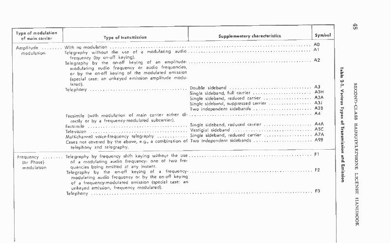
14.
CeD
Type of modulation of main carrier Type of transmission Supplementary characteristics Symbol
Amplitude With no modulation modulation Telegraphy without the use of a modulating audio
frequency (by on-off keying). Telegraphy by the on-off keying of an amplitude-
modulating audio frequency or audio frequencies, or by the on-off keying of the modulated emission (special case: an unkeyed emission amplitude modu-
lated). Telephony
Facsimile (with modulation of main carrier either di-rectly or by a frequency-modulated subcarrier).
Facsimile Single sideband, reduced carrier A4A Television Vestigial sideband A5C Multichannel voice-frequency telegraphy Single sideband, reduced carrier A7A Cases not covered by the above, e.g., a combination of Two independent sidebands A9B
telephony and telegraphy.
AO A 1
A2
Double sideband A3 Single sideband, full carrier A3H Single sideband, reduced carrier A3A Single sideband, suppressed carrier A31 Two independent sidebands A3B
A4
Frequency Telegraphy by frequency shift keying without the use (or Phase) of a modulating audio frequency: one of two fre-
modulation quencies being emitted at any instant. Telegraphy by the on-off keying of a frequency- F2
modulating audio frequency or by the on-off keying of a frequency-modulated emission (special case: an unkeyed emission, frequency modulated)
Telephony
Fl
F3
Table 2-1. Various Types of Transmission a
nd Emission
SECOND-CLASS RADIOTELEPHONE LICENSE HANDBOOK

Facsimi le by direct frequency modulation of the F4 carrier.
Television F5
Four-frequency diplex telegraphy F6
Cases not covered by the above, in which the main F9 carrier is frequency modulated.
Pulse modulation .. A pulsed carrier without any modulation intended to carry information (e.g. radar).
Telegraphy by the on-off keying of a pulsed carrier without the use of a modulating audio frequency.
Telegraphy by the on-off keying of a modulating audio frequency or audio frequencies, or by the on-off keying of a modulated pulsed carrier (special case: an unkeyed modulated pulsed carrier).
PO
P 1 D
Audio frequency or audio frequencies modulating the P2D amplitude of the pulses.
Audio frequency or audio frequencies modulating the P2E width (or duration) of the pulses.
Audio frequency or audio frequencies modulating the P2F phase (or position) of the pulses.
Telephony Amplitude-modulated pulses P3D
Width- (or duration-) modulated pulses P3E Phase- (or pcsition-) modulated pulses P3F Code-modulated pulses (after sampling and quantiza- P3G
tion). Cases not covered by the above in which the main P9
carrier is pulse modulated.
Table 2-1. Various Types of Transmission a
nd Emission—Cont
TRANSMISSION CHARACTERISTICS
co

50 SECOND-CLASS RADIOTELEPHONE LICENSE HANDBOOK
audio-frequency component being 3000 Hz. The total bandwidth would be 6 kHz.
2-2-1. Suppressed Carrier
Some voice-communication circuits, both base-mobile and point-to-point, use suppressed-carrier transmission, as shown in Fig. 2-4. In the a-m modulation process, the information to be conveyed between two points is contained in either sideband. The carrier itself is excess bag-gage—it really contains no useful information. Its presence does sim-plify receiver design, and the carrier can be put to work in the form
A-M DSB 100% MOD 3» MOD
Fig. 2-4. Suppressed-carrier and single-side-
band transmission.
6kHz
ISUPPRESSED CARRIER
SINGLE SIDEBAND
I-3kHz BANDWIDTH
of avc and afc. However, with appropriate receiver design it can be dis-pensed with, or at least transmitted at a much reduced level.
In conventional a-m systems with 100% modulation, two-thirds of the transmitted power is in the carrier and only one-third in the useful sidebands. For modulation percentages of less than 100% (usually the case except on peaks), the ratio of the power in the carrier to that in the sideband is substantially higher. As a result, a lot of transmitter power is wasted in the formation of the carrier. Furthermore, it is the interaction of carriers and sidebands that sets up the whistles and squeals which hamper communications under crowded conditions. Thus, if the carrier is reduced or suppressed, a source of interference is also removed. Two other advantages of reduced-carrier transmission are the econo-
mies of transmitter design, and the fact that all useful available power can be concentrated into the information-carrying sidebands. Receiver design is more complex because a stable substitute for the carrier must be generated within the receiver.

TRANSMISSION CHARACTERISTICS 51
2-2-2. Single Sideband (SSB) Still another form of a-m transmission with wide-acceptance in ma-
rine point-to-point and amateur communications is single-sideband, suppressed carrier. This type of transmission is symbolized as .4.3/. The symbol 3A3J designates single-sideband transmission with a high-frequency limit. In single-sideband transmission, not only is the carrier recovered or reduced substantially, but one sideband is also sup-pressed. Hence, as shown in Fig. 2-4, the required bandwidth of the signal has been cut in half. The total bandwidth of 3.131 transmission thus is only :3 kHz.
Fig. 2-5. Basic fm wave with a 25-MHz carrier.
I NO MOD MAX MIN NO MOD CENTER FM FM CENTER FR EQ FR EQ FR EQ FRECI
MODULATING WAVE
FM RESULTANT WAVE
In addition to the conservation of frequency in the spectrum, single-sideband transmission requires less power and further narrows the bandwidth to reduce interference. In two-way radio systems, single-sideband transmission is used more frequently for fixed point-to-point services. However, it can be expected in some, and anticipated in more and more, mobi:e installations. Radio amateurs have demonstrated its capabilities in mobile installations. The power-saving feature of single-sideband transmission is obvious
when we consider that, with conventional double-sideband am 100% modulation, only one-sixth of the total power is contained in each side-band. Nonetheless, all the information to be conveyed is contained in one of the sidebands. With single-sideband transmission, all the avail-able power of the transmitter can be concentrated into this one side-band. The narrnw bandwidth and the absence of a carrier are very important interference-reducing characteristics.
Single-sideband transmission has become increasingly popular for transcontinental and intercontinental communications. It is somewhat less subject to ionospheric variables, and less troubled by selective fading, than other methods of transmission. With selective fading, some frequency segments of a transmitted signal fade more or less than others. This condition produces intermodulation distortion in the re-ceiver and results in garbled speech. With only one sideband and a narrow bandwilth, such fading becomes less objectionable.
In many radi.) services single-sideband transmission is replacing con-ventional doub:e-sicleband a-m modulation. This changeover has been

52 SECOND-CLASS RADIOTELEPHONE LICENSE HANDBOOK
proceeding on the radio amateur bands for some time. Sideband has almost completely replaced conventional a-m on most bands. Some of the fixed commercial services have also used sideband for a number of years. In fact, in some of the commercial services, particularly on the medium-frequency marine band, sideband has become compulsory and a-m is being phased out.
In the 1.605- to 4.000-MHz spectrum commercial A3 assignments are no longer available. Furthermore those transmitters employing A3 emission which were issued prior to January 1, 1972 may continue to operate only until January 1, 1977. There are three recognized sideband emissions (2.8A3H, 2.8A3A, and
2.8A3J). The 2.8 represents the highest permissible modulating audio frequencies. The 3 refers to the total bandwidth of 3 kHz. The H-form of emission refers to one sideband and full carrier. The A-form is one sideband and partial carrier, while the J authorization refers to one sideband and completely suppressed carrier. In certain portions of the medium-frequency spectrum even the H-type will be abolished after a certain cut-off date.
2-2-3. Frequency Modulation (FM)
two-way mobile-radio systems, the use of frequency modulation has a number of advantages. The ignition systems of moving vehicles are a source of impulse noises, which appear as amplitude variations on the incoming rf signals. When a-m transmission is used, noise varia-tions cannot be suppressed entirely, because of the hazard of also sup-pressing the desired amplitude variations of the incoming signals. In a frequency-modulation system, the desired information is in the form of a frequency deviation of the wave. Consequently, any amplitude varia-tion introduced can be reduced almost completely without endanger-ing the desired information carried by the incoming radio signal. The very nearness of the noise source to the receiver, as in a moving
vehicle, makes the frequency-modulation system attractive for mobile communications. In the uhf, vhf, and high hf bands, frequency modu-lation is the more common form for mobile communications. Although amplitude modulation is used for some services in these spectra, it is much more common in the short-wave and low-frequency half of the high-frequency (hf) band.
In an fm system, as shown in Fig. 2-5, the carrier is frequency modu-lated by the incoming signal. The frequency of the transmitted wave increases sinusoidally during the positive alternation of the modulating sine wave. The greatest upward frequency deviation (+5 kHz from the carrier) occurs at the positive crest of the modulating wave. As the modulating sine wave swings toward the zero axis, the frequency de-creases sinusoidally to the carrier, or center, frequency. On the negative alternation, the frequency of the transmitted wave decreases with re-spect to the center frequency. The greatest downward swing away from the center frequency occurs at the crest of the negative alterna-tion ( —5 kHz from the center frequency). The frequency-change limits of the fm wave determine the frequency
deviation. In the example shown, the deviation is --L-5 kHz. In assigning

TRANSMISSION CHARACTERISTICS 53
a channel for fm transmission, the FCC specifies 100% modulation as the maximum deviation permissible for the particular class of station. This maximum frequency deviation corresponds to the 100% modula-tion limit of an a-m wave which, as shown previously in Fig. 2-3, occurs when the wave rises to twice the original carrier amplitude at the posi-tive crest of the modulating wave, and falls to zero at the negative crest.
This maximum fm modulation is not the same for each type of service. The maximum permissible deviation (100% modulation) is =75 kHz for fm broadcasting stations. For the fm sound signal associated with television broadcasting, it is =25 kHz. For most two-way fm radio sys-tems, 100% modulation corresponds to =5 kHz depending on the sta-tion classification. It is important that the second-class radiotelephone operator know the maximum deviation permitted for the type of gear he must adjust or repair.
In an fm system, it might be assumed that the total transmission bandwidth is determined by the maximum deviation of the resultant wave. However, like the a-m wave, the fm wave is a composite of the carrier or center frequency and a number of sidebands. Unlike the a-m wave, however, which has only one pair of significant sidebands, the fm wave (Fig. 2-6) has one or more pairs of significant sidebands.
MODULATION INDEX I
MODULATION INDEX I 4
CARRIER
-45 -30 -15 0 +15 +30 .45 ± 15 Hz DEVIATION
90kHz BANDWIDTH
CARRIER
111111i -10.51-3.5 0+15+7+105
±5kHz
DEVIATION
21 kHz - -I BANDWIDTH
15kHz-DEVIATION 15kHz-HIGHEST AUDIO
5kHz-DEVIATION 3.5kHz HIGHEST AUDIO
Fig. 2-6. Fm sideband and distribution as infl d by the modulation index.
They are a function of the modulation index which, at the highest modulating frequency, determines the number of pairs and hence the bandwidth of the fm transmission.
Deviation Modulation Index = Modulating Frequency
The sideband pairs are separated from the center frequency by the frequency of the modulating wave and by its harmonic multiples (2, 3,

54 SECOND-CLASS RADIOTELEPHONE LICENSE HANDBOOK
4, 5, etc.). If an fm wave for a given maximum deviation has three sig-nificant sideband pairs, the total bandwidth is 2 x 3 x the highest modulating frequency. If the highest modulating frequency is 10 kHz, the total bandwidth required would be 60 kHz (2 x 3 x 10,000).
If the highest modulating frequency is reduced to 3 kHz, the total bandwidth required by the fm transmission will be only 18 kHz (2 x 3 x 3000). It is significant, just as in a-m practice, that reduction of the highest audio frequency reduces the bandwidth.
In fm broadcasting, particularly for high-fidelity transmission, the highest audio frequency is over 12 kHz. As we learned in communica-tions, the best intelligibility is obtained by limiting the highest audio frequency to 3000-4000 Hz. Consequently, the fm wave used for com-munications can be crowded into a much narrower bandwidth than is required for fm broadcasting.
Another method of reducing the bandwidth of fm transmission is to reduce the amount of deviation. In an fm system the best noise rejec-tion is obtained with the greatest deviation. For this reason, the nar-row-band system (nlifm) has a poorer noise rejection. However, the signal-to-noise ratio improves when the highest audio frequency is re-duced. Inasmuch as the highest audio frequency for a voice communi-cations service is much lower than required in broadcasting, it is possi-ble to obtain a very fine signal-to-noise ratio despite the much more confined deviation of an nbfm system.
IJ
CARRIER ON
CARRIER OFF
LE"
MODULATION ON
-)VIAAAAMA 4i ,10
0 0 1.1 11 11 till 1.1 1, é .
MODULATION PG!,
CONTINUOUS CARRIER
Al
Fig. 2.7. Al and A2 code transmission—Morse code letter Las an example.
The symbols for fm emission are shown in Table 2-1. The two-way radio assignments are predominantly F3. A numerical prefix establishes the permissible bandwidth. For example, 18F3 signifies fm telephony with a total bandwidth of 18 kHz. The second-class radiotelephone license applicant should also be
familiar with some symbols of the other common forms of transmission. Symbol Al is given to radiotelegraphy, in which the carrier is inter-rupted in accordance with a coded message (usually International

TRANSMISSION CHARACTERISTICS 55
Morse code). In this form of transmission, the carrier is turned on and off, as shown in Fig. 2-7. Another form cf radiotelegraphy, common on the low- and very low-
frequency ship bands, is A2. Here the carrier is transmitted continu-ously, but is modulated by an audio tone in accordance with the coded message. For example, an 800-Hz audio tone could be used. The tone is turned on and off to simulate the dots and dashes (marks) and spaces of the International Morse code. Symbols Fl and F2 represent methods of sending frequency-modu-
lated coded messages. Numbers 4 and 5 represent facsimile and tele-vision transmission, respectively. An A or F prefix is used, depending on whether a-m or fm modulation is employed. In television broadcasting, A5 is used for picture transmission and F3 for sound.
Various types of pulse modulation can be noted in the last section of the chart. Pulse-modulation techniques are used in advanced multi-plex and telemetering applications. Their discussion is beyond the scope of this handbook.

CHAPTER 3
Test Equipment and Methods
Test instruments—both simple and complex—are needed to adjust, monitor, and troubleshoot the transmitters and receivers of two-way radio systems. For some transmitter measurements, the accuracy must be well within the two-way radio performance tolerances established by the FCC. Moreover, not only must the test equipment be of good quality, but it must be used very carefully as well. The FCC is concerned primarily with the operating frequency and
its stability, the power output, and the modulation level of the commu-nications transmitter. The test equipment must be capable of making these measurements accurately. Otherwise, it would be difficult to de-termine whether the transmitter is complying with FCC technical standards. These tests must be performed by an operator with a second-class radiotelephone license or higher. The owner of a two-way radio system is also interested in additional
performance criteria. He is concerned with reliable, intelligible, and interference-free communications. To him, transmitter and receiver performance are of equal importance. The base and mobile transmit-ters must convey a good signal within the area served by the installa-tion. Transmitter power output and modulation levels must not be permitted to decline and should be held near, but not beyond, the maximum limits set by the FCC. The receiver sensitivity and stability must be maintained at a high level. It is preferable to keep the equip-ment in such condition that it can be used for long periods without retuning and service. The operators of such equipment are not expected to have technical
knowledge beyond turning the equipment on and off and switching from transmit to receive and back. It is imperative then that the tech-nician in charge of the system know how to use the test equipment in a manner that will keep the system in top operating condition.
3-1. REQUIRED TEST EQUIPMENT
Two or three pieces of test equipment are needed to check out a transmitter to make sure it complies with FCC technical regulations. One such instrument is an accurate frequency meter, used to determine
56

TEST EQUIPMENT AND METHODS 57
if the transmitter is set exactly on the assigned frequency. Of course, such an instrument also permits the operator to tune the transmitter to its assigned frequency. The same meter is generally used for checking the frequency stabil-
ity of the transmitter. Once a transmitter is set on its assigned fre-quency, its frequency drift may be no more than that permitted by FCC regulations. Generally, this requirement is stated as a percentage of the assigned frequency.
Modulation meters are required for checking the percentage of modulation, to make certain it is no greater than that permitted by FCC regulations. In an fm system, 100% modulation represents a maximum frequency deviation of -±-5 kHz for some installations, and for other services a maximum deviation of -±2 kHz or -±15 kHz. Again, the modulation meter not only is useful in making certain that 100% modu-lation is not exceeded, but also permits the technician to tune the trans-mitter for adequate deviation.
Coverage and reliability are improved if the transmitter is made to deviate to its maximum limit on modulation peaks. Most transmitters include special circuits which prevent instantaneous modulation peaks in excess of 100%.
For a-m communications systems, the amplitude modulation must not exceed 100%. A test setup can be arranged to measure the actual amplitude-modulation percentage. Here again, the modulation level should be adjusted as high as possible (average above 70%) for the greatest coverage and reliability. At the same time, modulation peaks should not exceed 100%. In a-m transmitters, too, special circuits are usually incorporated to prevent modulation peaks from overmodulat-ing the transmitter. An accurate power-output meter is helpful in deriving the best per-
formance from each transmitter. The assigned power output should not be exceeded. However, reliability and coverage can be improved if the transmitter operates at its assigned power output. A power-output meter is helpful in the attainment of maximum power output. Most commun:cations transmitters are FCC-approved and do not
require an accurate power-output measurement. If the transmitter is operated according to its accompanying instructions, it can be assumed to be operating at the rated power output. Such transmitters, when operated in accordance with the tune-up instructions, are not capable of delivering more than the rated output. When the de input power (II Eb) is normal, one can be reasonably certain the rated power out-put of such a transmitter is being obtained. The maximum permissible power is presented in terms of power input to the final stage. Whether this type of transmitter or the one that requires power-
output measurements is employed, a power-output indicator is useful— if for no other reason than making certain the transmitter is matched to the antenna system. When the two are matched, the antenna radi-ates almost the total power that the transmitter is capable of delivering. Some radio-frequency indicators can be inserted into the transmission
path, between transmitter and antenna, to measure the standing-wave ratio on the transmission line. This type of instrument is very useful in

I utiT
58 SECOND-CLASS RADIOTELEPHONE LICENSE HANDBOOK
measuring radiation from the line, and in making certain that maximum energy is transferred between the transmitter output and the antenna.
Simpler test equipment such as radio-frequency output indicators, absorption wavemeters, grid-dip oscillators, and others are useful in transmitter tune-up and receiver adjustments, and in the localization of trouble in the two-way radio system. An accurate signal generator is particularly important in receiver
alignment. Many of these receivers have an extraordinary sensitivity, down to 1 microvolt or less. This sensitivity is possible only if the cir-cuits have been critically aligned and the receiver carefully tuned. Keep in mind that many of these receivers are fixed-tuned—the user has no way of tuning in the signal if it is absent or mushy. Some standard pieces of electronic test equipment such as a vom,
vtvm, capacitor checker, oscilloscope, and other component testers are helpful, too.
OSCILLATOR OR OTHER
TRANSMITTER STAGE
MAX IMUM ENERGY TRANSFERRED AT RESONANCE
TRANSMITTER TANK CIRCUIT
CAPACITOR DIAL IS
CALIBRATED
T E
MAXIMUM I AND E AT RESONANCE
Fig. 3-1. Principle of the absorption wave-
meter.
3-2. THE ABSORPTION WAVEMETER
The basic radio-frequency indicator and frequency meter is the ab-sorption wavemeter shown in Figs 3-1 and 3-2. It is hardly more than a calibrated resonant circuit which, when coupled near the source of radio-frequency energy, can withdraw some of the energy. This meter will absorb maximum energy when tuned to the same resonant fre-quency as the source. Some form of radio-frequency indicator such as a lamp, neon bulb,
or diode and dc-meter combination can be used to indicate the relative
DIODE
I DC
Courtesy RCA
Fig. 3-2. Indicators for absorption wavemeters.

TEST EQUIPMENT AND METHODS 59
strength of the energy absorbed by the resonant circuit of the wave-meter. When the wavemeter is tuned to the frequency of the radio-frequency source, the indicator will read maximum; but if tuned to either side of the resonant-energy frequency, the meter reading or lamp brilliancy will decrease.
If the resonant frequency of the wavemeter tank circuit is known from the dial sett:ng, the frequency of the radio-frequency energy can be determined. Usually the capacitor dial of the Nvavemeter is cali-brated in frequency. Therefore, the setting of the pointer on the cali-brated scale, when the capacitor is tuned for maximum rf indication, shows the frequency of the rf signal being measured. In other absorp-tion wavemeters, the dial is calibrated from 0 to 100, and the exact reso-nant frequency cf the absorption tank circuit is determined from a chart. Wavemeters are usually equipped with replaceable coils so they can
be made to operate on different frequency bands, with a separate dial or calibration chnrt for each band.
3-2-1. Using the Wayemeter
Energy from the tank circuit of the unit under test is coupled into the resonant circuit of the wavemeter. Use loose coupling to minimize loading the circuit under test, and couple the absorption wavemeter only close enougn to the radio-frequency source to permit a usable rf indication ( lamp glow or de meter readings ). To provide minimum loading and additional convenience, some ab-
sorption wavemeters include a low-impedance pickup coil. The main meter coil remains part of the wavemeter proper and is not coupled close to the radio-frequency energy being measured. The small pickup loop is coupled tu the source of energy and transfers the small amount needed into the absorption-wavemeter circuit (Fig. 3-3).
Fig 3-3. Absorption wavemeter with pickup loop and phone jack.
PICKUP LOOP
MA
PHONE JACK
The absorption wavemeter is important in making approximate fre-quency measurements while a transmitter is tuned, and, in particular, for checking multiplier harmonic outputs. It also serves as a good indi-cator of the strength of the radio-frequency energy. When set at a fixed position from the energy source, the influence of tuning on the radio-frequency output can be noticed immediately. Most absorption wavemeters also include a phone jack into which a
pair of headsets can be plugged and any a-m modulation on the rf sig-nal can be heard. Hence, when the absorption wavemeter is used to

60 SECOND-CLASS RADIOTELEPHONE LICENSE HANDBOOK
check out rf amplifiers that convey a modulated rf signal, the quality of that modulation can be tested approximately, using the detector circuit that is part of many absorption wavemeters. For proper demodulation of an fm radio-frequency signal, some form of fm detector would have to be associated with the wavemeter.
3-2-2. Wavemeter as an RF Indicator The wavemeter principle can also be used as a sensitive radio-
frequency output indicator. In fact, it is no problem to attach a small antenna to a wavemeter, as shown in Fig. 3-4, to make it even more sensitive to the radio-frequency output of a transmitter.
WHIP ANTENNA
INDICATOR CIRCUIT
Fig. 3-4. Use of the wavemeter principle in an
rf indicator.
If the wavemeter is tuned to the operating frequency of the trans-mitter and placed somewhere in its immediate field, a strong indica-tion can be obtained. It is in effect a field-strength indicator. With the meter positioned a fixed distance from a transmitter, various tuning ad-justments can be made to maximize the rf output. In fact, the wave-meter, if placed in the field of the transmitter antenna, permits a rather good indication of the tuning of the antenna system and the effective-ness of energy transfer from transmitter to antenna.
3-3. TUNING METER
A nonresonant rf indicator is shown in Fig. 3-5. This is a very popu-lar instrument for field checking the power output and tuning of corn-
WHIP ANTENNA
C 1
PHONE JACK
Fig. 3-5. A typical rf field indicator.
munications transmitters. It consists of a crystal diode and a sensitive de meter. The indicator is a simple rectifier and filter circuit. Capacitor CI, inductor Li, and potentiometer RI function as a filter to smooth out the unidirectional detector pulses. Thus, the steady current through

TEST EQUIPMENT AND METHODS 61
the de meter is a function of the signal strength at the input. To im-prove the sensitiv:ty of the device, particularly when hf and vhf signals are being checked, a short antenna can be attached. Sensitivity can be adjusted with potentiometer Rl. The amount of resistance inserted into the circuit influences the amplitude of the current through the de meter. A tuning meter of this type, when placed near the transmitter an-
tenna, will indicate the relative power output of the transmitter, and the effect of any transmitter adjustment on the power output can then be noted.
It must be stressed that this type of rf meter, being untuned, is sensi-tive to an extremely wide frequency range. For this reason, a meter of this type cannot be used to check the transmitter frequency.
3-4. GRID-DIP OSCILLATOR
The grid-dip oscillator is a useful test instrument for checking trans-mitter circuits. Most grid-dip oscillators can also be used as absorption wavemeters. The Millen grid-dipper uses a high-frequency triode connected in a
Colpitts circuit, as seen in Fig. 3-6. Seven plug-in coils permit operation over a frequency range between 1.7 and 300 MHz. With use of the log-ging scale and an included calibration curve, the unit also functions between 165 kHz and 1.7 MHz. Plug-in coils provide overlapping fre-quency ranges between the two frequency extremes.
Fig. 3-6. Millen grid dip oscillator.

62 SECOND-CLASS RADIOTELEPHONE LICENSE HANDBOOK
The meter sensitivity is increased with the use of a solid-state de amplifier, transistor Ql. In the operation of a grid-dip oscillator, the loading effect of the external resonant circuit being measured causes a drop in the oscillator grid current. A tiny change in de current is am-plified by the transistor, resulting in a useful meter reading. The dial of the variable capacitor of the grid-dip oscillator is cali-
brated in frequency. When used with the appropriate calibrated coil, the oscillator frequency can be read with reasonable accuracy.
As a grid-clip oscillator, the test unit can be used to determine the resonant frequency of a de-energized radio-frequency tuned circuit. When a resonant circuit is brought close to the oscillating tank circuit, the tuned circuit under measurement absorbs some of the energy from the oscillator tank circuit. (Refer to Fig. 3-7A.) Inasmuch as energy is removed from the tank circuit of the grid-dip oscillator, the oscillator feedback into the grid circuit decreases. As a result, the grid-current meter reading drops. When the grid-dip oscillator is set on the exact frequency of the reso-
nant circuit under measurement, the meter will dip to its minimum value. This setting indicates that the grid-dip oscillator is generating a signal of the same frequency as the resonant tuned circuit under check.
It is apparent that the grid-dip oscillator is very helpful in determin-ing the resonant frequency of various types of tuned circuits. Be it a small, weak-signal resonant circuit of a receiver or the larger, higher-powered resonant circuit of the transmitter final amplifier, the resonant frequency can be determined without any signal present. In transmitter circuits the grid-dip oscillator can also be used to track down spurious resonant conditions that cause parasitic oscillations. A grid-dip oscillator can also be utilized as a signal generator, as
shown in Fig. 3-7B. Therefore, it can be used in signal-tracing a com-
UNENER GI ZED RESONANT CIRCUIT ® TUNE FOR DIP
ANTENNA INPUT
0000.00000C
F RECEIVER
UNDER CHECK
(A) To determine resonant frequency of a de- (B) As a signal generator.
enerized circuit.
(C) As a detector.
00000000000
SIGNAL SOURCE
HETERODYNE FREQUENCY
METER
o •
TUNE FOR ZERO BEAT
Fig. 3-7 Using the grid-dip meter.

TEST EQUIPMENT AND METHODS 63
munications receiver, and if the oscillator can be calibrated very accu-rately, for alignment work to a limited extent. The grid-dip oscillator can also be employed as an oscillating de-
tector, similar in action to a heterodyne-frequency meter. In this ap-plication, as shown in Fig. 3-7C, the grid-dip oscillator is brought near the source of rf energy. A pair of headphones, inserted into the phone jack, will pick up a beat note when the frequency of the grid-dip oscil-lator is brought near the signal-source frequency. If this note is zero-beat, the grid-dip oscillator is set to the same frequency as the source of the signal. In this application the grid-dip oscillator has been used for determining the frequency of an unknown signal source.
3-4-1. Grid-Dip Oscillator Calibration
The oscillating-detector principle of the grid-dip meter can in itself be used to calibrate the meter accurately, as shown in Fig. 3-8. In this
._,00000000
FREQUENCY STANDARD
HETERODYNE METER •
TUNE FOR ZERO BEAT
• I AS GRID-DIP OSCILLATOR
(A) Using a frequency standard. (B) Using a communications receiver.
WWV SIGNAL
— COMMUNICATIONS RELIEVER o
Fig. 3-8. Calibrating a grid-dip meter.
check, it is coupled near a crystal-controlled frequency standard. When-ever the grid-dip oscillator is tuned to the crystal frequency or to one of its harmonics, a beat note will be heard. At the beat-note position, the grid-dip calibration should be checked. Some grid-dip oscillators provide a calibration control so the oscillator can be reset if it has drifted.
Still another method of checking the calibration of a grid-dip oscil-lator is to tune a communications receiver to a WWV frequency (2.5, 5, 10, 15, 20, and 25 MHz), as in Fig. 3-8B. The grid-dip oscillator is then tuned to the same frequency. When a zero beat is heard at the receiver output, the grid-dip oscillator has been set to the same fre-quency as the incoming WWV signal. The dial calibration can be checked at this point.
3-4-2. Grid-Dip Oscillator as an Absorption Wavemeter
When the oscillator tube is turned off, the grid-dip oscillator becomes an absorption wavemeter. The tube functions as a diode and the meter becomes part of the diode-load circuit. When coupled near and tuned to the frequency of an rf energy source, the meter will display a current increase. The operation is similar to that discussed for absorption wavemeters. The grid-dip oscillator has many applications in testing and tuning
transmitter circuits. The obvious applications are for tuning tank cir-

64 SECOND-CLASS RADIOTELEPHONE LICENSE HANDBOOK
cuits and checking the output. Other applications include use as an rf indicator in neutralizing various stages of the transmitter, or in tracking down troublesome parastic oscillations. It is also helpful for peaking various types of resonant traps used in transmitters to prevent parasitic oscillations, or for preventing the transfer of strong harmonic compo-nents from stage to stage and from the transmitter to the antenna sys-tem. Finally, the grid-dip oscillator is handy for checking antenna per-formance. It can be used in bringing the antenna system to resonance and in minimizing standing waves on the transmission line.
3-5. POWER OUTPUT
To minimize interference and to be fair to all users of two-way radio equipment, transmitters must adhere to certain performance standards in the form of specific FCC technical rules and regulations. These standards cover frequency of operation, frequency stability, modula-tion level, and power output. Suitable test instruments are available for testing these transmitter characteristics. They must be capable of making measurements within the tolerances established by the FCC. The maximum power output of the transmitter must comply with the
maximum ratings established by the FCC for a particular service. As mentioned previously, the power output is set indirectly by the maxi-mum power input restrictions of the FCC. Power-output measurements are not required for approved units. It is assumed that if the accom-panying instructions are followed with regard to the power input, the output will not be excessive. An rf power-output meter is helpful to the communications techni-
cian who does much work in this field. It permits him to determine if a given transmitter does function efficiently, and helps him tune up the transmitter in a manner which will give the owner as strong a signal as possible without exceeding the FCC maximum input rating. Power output can be measured by attaching a dummy load to the
transmitter output. The dummy load should have the same impedance as the antenna system into which the transmitter normally works. An rf ammeter (Fig. 3-9) can be inserted into the dummy-load circuit. Power output will be:
P = I2R
A calibrated rf voltmeter can also be used to measure the rf voltage across the dummy load. In this case the rf power output is:
P = E2/R
TRANSPAITTER UNDER TEST
DUMMY LOAD Dl,
CALIBRATED
RF CURRENT METER
IN RF VOLTS. OR WATTS
Fig. 3-9. Rf power measurement.

TEST EQUIPMENT AND METHODS 65
An rf voltmeter is generally a crystal diode rectifier and a sensitive dc meter calibrated to measure rf voltage. The technician can build up a matched dummy load by using paralleled resistors, a coaxial fitting, and a mount, as shown in Fig. 3-10. The 50-ohm dummy can be plugged into the antenna-output fitting of the transmitter. Resistors should have proper ratings for dissipating the output power of the transmitter.
Fig. 3-10. Home-constructed dummy load.
COAXIAL L ONNECT OR
PARALLELD RESISTORS
BAG K PLATE
3-4. COMMERCIAL RF POWER METERS
A problem in making rf power measurements is that the circuit oper-ating conditions change when the test instruments are inserted across the transmitter output or into the transmission-line path between the transmitter and antenna system. Commercial instruments, referred to as insertion-type rf wattmeters, provide the answer to this problem.
Insertion-type wattmeters are the ones made by Bird Electronics Corporation and are shown in Figs. 3-11 and 3-12. Units are designed specifically for line insertion between a 50-ohm transmitter output and a 50-ohm antenna system. As shown in Fig. 3-12, it is inserted between the transmitter output and the coaxial transmission line going to the antenna system. Various plug-in termination elements-are made avail-able. By insertion of the proper elements or by switching seven wattage ranges can be measured-0-2.5, 0-10, 0-25, 0-50, 0-100, 0-250, and 0-500. The instrument responds to the direction of wave travel and is
capable of measuring the power in the forward wave traveling between transmitter and antenna, as well as the power lost in the reflected wave traveling back toward the transmitter because of a mismatch in the antenna system. It is apparent that the rf wattmeter is helpful not only in making power measurements, but also in tuning the transmission line and antenna system for a minimum standing-wave ratio to insure the most efficient transfer of power from transmitter to antenna. The wattmeter and coupling system are shown schematically in Fig.
3-12. The rf energy, passing between transmitter and antenna, is sam-pled by a pickup element and applied to a crystal diode and rectifier. A rectified and filtered dc current is then linked by a meter cable to a current meter with a sensitivity of 30 microamperes. To prevent meter and crystal damage, it is important that the proper size of plug-in ele-ment be used and that it be inserted correctly. A complete coupling circuit which samples the traveling wave is
mounted in each individual plug-in element. It consists of the pickup

66 SECOND-CLASS RADIOTELEPHONE LICENSE HANDBOOK
Courtesy B
Fig. 3-11. Rf wattmeters.
rd Electronic Corp.
METER. VAMPS DL 15200
METER CARIE
XMIR LOAD OR OR LOAD XMTR
DIRELf IONA( COUPLING
CRYSTAL DIODE
ELEMENT
DC CONNECTOR
BYPASS
DC CONTACT
Fig. 3-12. Circuit of an rf wattmeter.

TEST EQUIPMENT AND METHODS 67
loop, crystal diode, and associated components. There are various plug-in elements corresponding to frequency and power rating. These are plugged into the front of the meter. The pickup element of the rf wattmeter functions as a directional
coupler. As shown in Fig. 3-13, the rf energy is conveyed to the crystal diode over two paths. One path is by way of capacitive coupling from the center conductor, which is part of the coaxial feedthrough arrange-ment. Radio-frequency energy is also inductively coupled into the pickup tube. By careful design, the two components are of equal am-plitude and are either additive or subtractive.
PICKUP LOOP
TO DETECTOR
ANT
TO DETECTOR
Fig. 3-13. Principle of a reflectometer.
PICKUP LOOP
REVERSED
ANT
The phase of the inductive component is a function of the direction of wave travel. :n the arrangement of Fig. 3-13A, the energy picked up from the wave traveling between transmitter and antenna adds to the capacitive component and produces a reading on the calibrated meter. Any reflected energy returning along the transmission line induces a voltage out of phase with the direct-coupled component from the re-flected wave. Consequently, the influence of the reflected wave is can-celed and its strength is not recorded. To read the reflected power, the coupling plug-in element is inserted
in the opposite direction, as shown in Fig. 3-13B. The reflected power induces into the coupling circuit a voltage in phase with the capaci-tively coupled component. Hence, the meter will read the reflected power. Insofar as the direct wave moving from the transmitter to an-tenna is concerned, the coupling loop is so connected that the induced component and the capacitive components are equal and opposite in polarity. The net voltage is zero; therefore, the direct power is not recorded on the meter.
This type of power meter, usually referred to as a reflectometer, has the ability to measure direct and reflected power. The power delivered to the antenna or other load can be calculated by subtracting the re-flected power from the direct power.
In using an rf power meter of this type, it is very important to insert a plug-in element of the proper size and in the proper direction. For example, the reflected power of a closely matched system is much lower than the direct power. To make an accurate measurement of the re-flected power therefore requires the use of a low-power plug-in ele-ment. Moreover, if this element is inserted in the improper direction,

68 SECOND-CLASS RADIOTELEPHONE LICENSE HANDBOOK
the strong direct power will be supplied to it, and the crystal and meter could be damaged.
3-7. FREQUENCY AND FREQUENCY-DRIFT MEASUREMENT
The FCC requires that each transmitter operate on its assigned fre-quency or frequencies. Furthermore, any drift from that assigned fre-quency must be maintained within strict tolerances. In most two-way radio services, the permissible percentage of drift is only 0.0005% at frequencies over 50 MHz. The very tight tolerances are necessary if an ample number of channels is to be provided for the many services using two-way radio. A transmitter should not drift significantly or it will interfere with similar two-way radios on adjacent channels. A minimum of drift is also very important in terms of reliability. Most installations use fixed-tuned receivers. Consequently, it is important that the trans-mitter maintain constant frequency in order to prevent distortion in the reproduced audio. The frequency meter must be of the highest quality, and its toler-
ances should be even stricter than those of the transmitter (0.00025% or better) if exacting frequency measurements are to be made. A signal generator with a drift tolerance of 0.0001% permits very accurate set-ting and measurement of transmitter frequency.
3-8. COMMERCIAL FREQUENCY METER
An example of all accurate frequency meter that uses a mixer and counter chain to develop a direct readout of the frequency is shown in Fig. 3-14. A 1-MHz crystal oscillator is the secondary frequency stan-dard. ( It can be locked in on the WWV signal.) A harmonic amplifier and a series of frequency dividers are driven by this crystal oscillator, to develop a series of suitable local-oscillator frequency components that are applied to a series of mixers ( Fig. 3-15). The signal of un-known frequency is heterodyned down in frequency through this series of mixers. Since the frequencies of the local oscillator components are set precisely, it is possible to divide an incoming signal into units cor-responding to hundreds of megahertz, tens of megahertz, megahertz, and fractional parts of a megahertz. In this manner, the exact fre-quency can be counted off. By using this method, highly accurate frequency measurements can
be obtained (±100 Hz with the 1-MHz crystal adjusted to WM' ). Specific accuracy figures in terms of frequency are 0.0004% at 25 mega-cycles, 0.00007% at 150 MHz, and 0.00002% at 450 MHz. Let us con-sider in greater detail the technique used to make an exact frequency measurement. The first mixer is shown at the lower left of the block diagram (Fig.
3-15). Note that it is supplied with signal from a harmonic selector. The harmonic selected corresponds to a particular two-way radio band. In the example shown, the frequency of the signal to be measured is in the 450-MHz band. In this instance the harmonic selector is set to read 4, indicating that the signal to be measured will fall between 400 and

TEST EQUIPMENT AND METHODS
e
t•t
at
•
MC
e,:
1111 11111 0 01100
•
•
STANDARD FREQUENCY METER
Eliab
e let. AIL St'
•
Fig. 3-14. Accurate frequency meter.
eni%Kc
4
MEASUREMENTS
wart
é
t.
69
Courtesy Measurements Corp.
500 MHz. If a signal in the 150-MHz band were to be measured, this harmonic selector would be set at 1. If a frequency in the 50-MHz band were to be measured, it would be set to zero. The specific mixing frequency chosen by the harmonic selector setting (50-MHz, 125-MHz, or 425-MHz) depends on the band of the transmitter frequency to be measured. The first mixing component is derived from a 1-MHz second-ary frequency standard using a harmonic amplifier as shown. In our example it will be the 425-MHz harmonic that will mix with the incom-
o
*****
met.e.la rt;Z:
o
C=E)'
.111.11..1
Fig. 315. Functional diagram of a divider-type frequency meter

70 SECOND-CLASS RADIOTELEPHONE LICENSE HANDBOOK
ing signal. Let us assume that the frequency of the signal to be mea-sured is that shown in the block diagram of Fig. 3-15. This frequency is 462.672500 MHz. What frequency will be present at the output of the first mixer?
Mixer 1 Output = 467.6725 — 425 = 42.6725 MHz.
This component is supplied to a follow-up tunable resonant circuit. This tunable circuit is next peaked using the first large tuning knob at the lower left of the instrument (refer to Fig. 3-14). Its correspond-ing meter will show a peak when the resonant circuit is tuned some-where between 67 and 68 on its readout scale. A small gain control to the lower right of the knob is then adjusted until the meter reading is a specific value. The peak output of this resonant circuit is now being applied to the second mixer. The local oscillator frequency to the second mixer must now be set
to a proper frequency. This is accomplished by setting the 1-MHz har-monic selector to correspond to the next lower main division as indi-cated on the first resonant circuit tuning scale. In this case it is 67. By so doing we now know the first three significant figures of the incoming frequency; these are 467. By setting the second harmonic selector to read 67, a proper harmonic frequency between 25 and 50 MHz has been selected and applied to the second mixer. The harmonic selector is such that the output of the second mixer will fall in the 2- to 3-MHz range. In this case the local oscillator frequency supplied by the second har-monic selector is 40 MHz. (This is the 40th harmonic of the 1-MHz crystal.) The second resonant circuit is now adjusted for a peak indi-cation on the second meter using the middle knob in the lower row. The knob adjustment will fall between 6 and 7 on the scale. As before, the harmonic selector will be set to the lower calibration; this time it is 6. Now, four digits of the unknown frequency have been found; these are 4676. By setting the third harmonic selector to six, the proper harmonic of
the 0.1-MHz ( 100 kHz) divider has been selected for mixing with the signal applied to the input of the third mixer (42.6724 MHz — 40 MHz = 2.6725 MHz). The output of the third mixer will fall between 200 and 300 kHz. When the third harmonic selector is set at 6, the local-oscillator frequency is the twenty-fourth harmonic of the 0.1-MHz divider, or 2.4 MHz. Consequently the frequency at the output of the third mixer is 272.5 kHz, or 2672.5 kHz — 2400.0 kHz. The third resonant circuit can be peaked for a maximum meter de-
flection. This maximum will fall between 7 and 8, causing the next fre-quency digit to be 7; the lower calibration is again chosen to set the last harmonic selector. The output of the final mixer fails between 20 and 30 kHz. This is accomplished by setting its local oscillator frequency. By properly setting the last harmonic selector to 7, it would be the 25th harmonic of the 0.01-MHz divider, or 250 kHz. Hence the output of the fourth mixer is 22.5 kHz, or 272.5 kHz — 250 kHz. The last resonant circuit provides the final readout (knob and scale
at far right of instrument). The knob is adjusted for a maximum read-ing on its associated meter. In the example given in Fig. 3-15 its reading

TEST EQUIPMENT AND METHODS 71
is 2.5. Therefore the complete readout has been made as 4676725 or 467.6725 MHz.
Input first mixe'
Output first har. sel.
Input second mixer
467.6725
—425.0000
Must fall between 25 and 50 MHz
42.6725
Output second har. sel. 40
Input third mixer 2.6725 Must fall between 2 and 3 MHz
Output third har. sel. 2.4
Input fourth mixer 0.2725 Must fall between 0.2 and 0.3 MHz
Output fourth har. sel. .250
Input final resonant cir. 0.0225 Must fall between 0.02 and 0.03 MHz
In a manner similar to the procedure for the 450-MHz band, a 150-MHz band signal can be measured. In this case the first harmonic selector is set to 125 MHz instead of 425 MHz. For a 50-MHz band sig-nal, the harmonic amplifier and first harmonic selector are not used; the first mixer becomes an amplifier and the 50-MHz band signal is then applied to the first resonant circuit.
3-9. FREQUENCY AND MODULATION METER
The Lampkin Communication Service Monitor 107C (Fig. 3-16) is a versatile test instrument that can measure the performance of two-way radio gear in compliance with the FCC Rules and Regulations. Its two principal functions are to check transmitter frequency and transmitter modulation. Its frequency accuracy is 0.00005% and well within the FCC-required accuracy. Frequencies can be measured be-tween 10 kHz and 1000 MHz; frequency deviation (fm), between 0 and 6 kHz. The unit has been designed specifically for the land mobile, public safety, marine, and aircraft radio services. Its accuracy of 0.5 parts-per-million permits its application in the a-m, fm, and tv broad-cast services as well as CATV. This is the type of instrument the sec-ond-class license holder must learn to operate when he becomes em-ployed in the two-way radio services. The service monitor can also be operated as a signal generator over
a frequency range extending from 1 kHz to 1000 MHz with the same accuracy. Its cutput can be cw, a-m, or fm modulated with an internal 50- to 6000-Hz modulating source. Its internal secondary frequency standard can be calibrated by a VVWV signal. Unit can be operated from 12-volts de as well as 115 and 220-volts ac.
3-8-1. Operation Five major activities take place within the test instrument. First there
is a synthesizer using decade dividers and a suitable mixing system to


TEST EQUIPMENT AND METHODS 73
generate a signal of a highly accurate frequency over the instrument range. It is this signal, when compared with an incoming signal in the detector (Fig. 3-17) that permits the instrument to make an accurate frequency measurement on an incoming signal. This same signal gen-erated by the synthesizer is also used as a signal source when the unit is to be used as a signal generator for receiver test, measurement and alignment. An audio amplifier and speaker permit you to listen to the incoming signal. The deviation meter permits you to make an accurate measurement of the transmitter deviation. An appropriate attenuator section serves as the input circuit when a transmitter is being tested or as a means of controlling the output level when the in-strument is used as a signal generator.
INPUT o OUTPUT
Fig. 3-17. Block plan for frequency and deviation
meter.
DETECTOR
FREQUENCY S YNTHES IZER
MODULATOR
AUD 10 AMP
DEVIAT ION METER
SECONDARY FREQUENCY STANDARD
Take a look at the control panel (Fig. 3-16). Except for the band switch at the lower left, the frequency synthesizer controls are located at the top left and the center. At the left is the megahertz setting fol-lowed by the 10 kHz and 100 Hz division settings. The final frequency setting control is the PPM adjustment. Examples of how to set the dials to a specific frequency are as follows:
De&ed Frequency Frequency Dials 455 kHz 0 45 50
4136.3 kIIz 4 13 63 10.7 MHz 0 70 00 26.965 MHz 6 96 50 43.16 MHz 3 16 00
157.685 MHz 7 68 50 459.425 MHz 9 42 50
For the first two frequencies the band switch must be set to position 1 covering the 10 kHz- to 10-MHz range. The MHz control must be set to the last digit of carrier MHz. In the case of 455 kHz this control must be set to zero. The second reading is for a 4-M Hz-plus signal fre-quency. Therefore the MHz dial is set to 4 as indicated. The remaining frequencies are given in the MHz range and the MHz dial is set accord-ing to the first digit to the left of the decimal point. Of course, for this group of frequencies the band switch must be set on position 2 ( 10- to 100-MHz range ). The third position of the band switch permits you to

74 SECOND-CLASS RADIOTELEPHONE LICENSE HANDBOOK
calibrate the synthesizer with the 3-MHz secondary frequency standard that is a part of the 107C service monitor.
In using the instrument to measure a transmitter frequency, the fre-quency synthesizer is set to the assigned frequency of that transmitter. The instrument as a signal generator is set in the same way to the fre-quency you wish to make available at its output. The output attenuator controls are located at the left while the modulator frequency adjust-ments are found at the low right. The procedure for making a transmitter frequency measurement is
as follows:
Set carrier frequency on FREQUENCY dials. Set front-panel controls. 1. All attenuators to zero. Variable attenuator full clockwise. 2. BAND switch to desired band. 3. MODULATOR AM/FM to off. 4. Meter switch to AUDIO. 5. AF VOLUME to half open. 6. IF LEVEL to half open. 7. Extend antenna. 8. Turn on carrier and rotate ERROR dial back and forth across beat
frequency audible signal. Stop on exact zero beat. Individual cy-cles should be audible.
9. Each error dial division is 0.0001%. Each division is also one cycle times the carrier MHz. A 155-MHz transmitter is 155 Hz high for an error dial reading of plus one division.
Note in particular the convenience of the error dial because it is able to given you an exact measure of just how many hertz the transmitter is off frequency. Each error dial division corresponds to 0.0001%, and, as indicated, an error dial reading of +1 indicates the transmitter is 155 Hz high if it is supposed to operate precisely on a frequency of 155 MHz. The deviation measurement control and meter are located at the
right. Note that the instrument can measure both positive and negative modulation peaks. One need only follow a simple test procedure:
Make the transmitter frequency measurement, then proceed with the deviation measurement. 1. Check MODULATOR AM/FM switch to off. 2. Set the meter switch to w LEVEL and adjust IF LEVEL to 1.0 volt. 3. Set the meter switch to FOS or rrEc deviation. 4. Offset 10 kHz FREQUENCY dial 10 divisions either way, preferably
toward dial center. 5. Key carrier and increase signal coupling for lowest meter indica-
tion ( best quieting). 6. Modulate carrier and read peak kHz deviation on top meter scale,
toggle switch set to 6 peak kHz. 7. Read peak kHz deviation on lower meter scale, toggle switch to
1.5.

TEST EQUIPMENT AND METHODS 75
3-9-2. General Operation
The basic oscillator of the frequency synthesizer is a stable 1-MHz crystal oscillator, center left of the functional block diagram of Fig. 3-18. Although highly stable, the frequency of this oscillator can be changed a limited amount with two controls. One of these is a calibrate adjustment and, in conjunction with the 3-MHz secondary frequency-standard oscillator (lower right of Fig. 3-18), is used to set the 1-MHz oscillator precisely on frequency. The other control is tunable and is the one that is adjusted when the front-panel PPM adjustment is varied. The output of the 1-MHz oscillator is applied to a harmonic genera-
tor and then tc a frequency divider. The outputs of the frequency di-vider are the two basic 100-Hz and 10-kHz synthesizer components. These two components are supplied to a dual-channel phase-locked loop (PLL) system. A basic phase-lock loop chain consists of a voltage-controlled oscil-
lator ( veo ), lock circuit, phase detector, and beat detector/sweeper combination ( Fig. 3-19). This feedback combination has as its function the setting of the veo on a specific harmonic of the frequency of the input signal from the frequency divider. It is held precisely on this fre-quency because of the comparison made in the phase detector. Any attempted drift develops a correcting de error voltage which holds the 'co precisely on frequency. An external manual adjustment is associated with each veo. These
adjustments correspond to the external front-panel frequency controls associated with the 10 kHz/div. and 100 Hz/ div. frequency control. When manual settings are made the beat frequency and sweep circuits go into operation. The manual adjustment brings the veo close to the desired frequency. Now the beat-frequency detector generates a beat signal corresponding to the difference between the veo output and the nearest harmonic of the 100-Hz input. This beat note then triggers the generat:on of a sweep voltage that is applied to the veo, moving the veo frequency to a point at which it can be captured within the activity range of the phase discriminator. Once this occurs the de con-trol voltage from the phase discriminator holds the system in phase lock on the desired harmonic of the signal from the frequency divider. There are two PLL chains, operating between 30.0 to 39.9 kHz and
970 to 1960 kHz. The two outputs from the two channels are applied to a double-balanced mixer which has an output tuned to the sum fre-quency. Fundamental and lower-sideband components are trapped and do not appear in the output. The net result is to produce an output with a possible frequency range of 1 to 2 MHz in precise 100-Hz increments.
/t is important to understand that the output is in 100-Hz increments. In other words, the output is not tunable between 1 and 2 MHz on a continuous basis. Rather it is tunable over this range in 100-Hz steps. This stepped output is handled automatically by the PLL circuits as the two external frequency control circuits are adjusted. This is the makeup of the signal that follows the path between blocks 4 and 7 in Fig. 3-18.

EXT MOD 50-10,000 Hz
MODULAT ION 05G ILATOR c•») 50-6000 Ft
18
VXO 1 MHz
HARK ON IC GENERATOR
1 10-MHz MULT IPLIER
I 0-MHz HARMONICS
DOUBLE BALANCED MIXER
0-MHz HARMONIC GENERATOR
9 10
FREQUENCY D IV IDER
• PLL•PHASE- LOCKED LOOP
I -MHz HARMONIC SELECTOR
1-8 MHz IN ok•
1 MHz STEPS
6
30.0-39.9-kHz PLL • AND
970 - to 1960 -kHz PLL •
WITH DOUBLE-BALANCED MIXER
13
DOUBLE - BALANCED MIXER
USB
LS B TRAP
SUM
1-2 MFtz
LOW PASS
BAND SELECT ION
0-10
MHz
12
IF LEVEL SET WITH METER
11
BAND SELECT ION
DETECTOR AND AUDIO AMP
PIN DIODE ATTENUATOR
14
BEAT AUDIO
SWITCHING
3 MH STANDARD CALIBRATING OSC ILLATOR
7
15
RF INPUT - OUTPUT 150 OHMS)
10 k Fiz- 1000 MFtz
DEVIAT ION SYSTEM
19 18
AUDIO AMP -C1
-1.• METER

TEST EQUIPMENT AND METHODS 77
The output of the harmonic generator (block 2) is also applied to a 1-MHz harmonic selector. The control associated with this circuit is located at the top left of the front panel ( Fig. 3-16) and is labeled the MHz control. This control sets the harmonic at the output of the 1-MHz harmonic selector and it can be any frequency between the fundamental and eighth harmonic of the 1-MHz input to the sector.
This signal is combined with the output from the PLL chain in the double-balanced mixer (block 7 in Fig. 3-18). Again a sum frequency is selected in the output. Therefore the signal in the path between blocks 7 and 8 can be any frequency which is a 100-Hz increment be-tween 0 and 10 MHz. Again these frequency possiblities are not in the form of a continuous-frequency spectrum but as a series of available 100-Hz increments.
INPUT
Fig. 3-19. Phase-locked loop plan.
PHASE DETECTOR
LOCK CIRCUIT
CL,
FREQ
BEAT DEfECTOR AND SWEEPER
Going back to the harmonic generator again you will notice that there is a signal path to the 10-MHz multiplier (block 9). Its output is supplied to a 10-MHz harmonic generator. In the signal path be-tween blocks 10 and 11 the signal can be any 10-MHz harmonic be-tween 10 MHz and 1000 MHz. The output from the double-balanced mixer is passed through two
band-selection circuits and an i-f level control (block 11). When opera-tion is in the 0- to 10-MHz range the output of block 12 is applied to the detector and audio amplifier ( block 14). This signal can be handled in two ways. When the unit is being used as a signal generator the sig-nal is transferred to the output attenuator and to the audio input-out-put receptacle. If a frequency measurement is to be made the incoming signal and the locally generated signal combine in the detector and produce a beat note in the output. Recall that in the final adjustment of measuring the frequency of an incoming signal the PPM dial, asso-ciated with the VX0 1-MHz oscillator (block 1), is adjusted for an exact zero beat. When the transmitter is modulated, the quality of the modulation can also be listened to by way of the audio amplifier ( block 16) and the speaker.
If the unit is to be operated on some 100-Hz increment between 10 MHz and 1000-MHz the double-balanced mixer (block 13) must be made active. Appropriate switching is handled by the band selection switch located at the lower left side of the front panel (Fig. 3-16). In this mode of operation the signal is linked between the band selection

78 SECOND-CLASS RADIOTELEPHONE LICENSE HANDBOOK
(block 12) and the double-balanced mixer (block 13). Here it is com-bined with 10-MHz harmonics. Again the output of the double-bal-anced mixer is tuned to a sum frequency making available outputs that are separated by 100-Hz increments between 10 MHz and 1000 MHz. The precise increase is selected by the frequency controls on the front panel and the resultant synthesized signal is applied tu the detector and audio amplifier circuit of block 14.
Block 17 supplies the 3-MHz secondary-standard signal. It is also applied to the detector and when the band selection switch is set to the calibrate position an appropriate beat note results which permits the technician to calibrate the 1-MHz VXO oscillator (block 1). The audio modulation oscillator is shown at the top left of Fig. 3-18. When the signal is to be frequency modulated the output of the oscillator is ap-plied to the harmonic generator. For a-m modulation the modulating signal is applied to the pin-diode attenuator. By varying the attenuation the output signal can be amplitude modulated before it is applied to the rf input-output receptacle. When the deviation of an incoming fm signal is to be measured it is
necessary to activate block 18. Note that the detector and audio ampli-fier output are applied to the input of the fm deviation circuit. Further-more the demodulated fm audio can be applied to the switching block 19 and then on to the audio amplifier. An important fact to understand is the manner in which the unit is
operated when a frequency-deviation measurement is to be made. In checking the frequency of a transmitter the locally generated signal is set precisely on the carrier frequency of the transmitter. After the fre-quency measurement is made and a deviation measurement is taken it is first necessary to shift the unit frequency 100 kHz away from the transmitter carrier frequency. This is accomplished by using the 100 kHz/div frequency control, moving it exactly 10 divisions ( corresponds to a 100-kHz change in frequency) away from the frequency measure-ment setting. As a result the signal transferred between blocks 14 and 18 will have a 100-kHz carrier frequency. Of course, this carrier com-ponent will be frequency deviated by the incoming modulation on the transmitter signal. In the circuit associated with block 18 it will be pos-sible to measure the peak frequency excursions of the 100-kHz fm wave. The fin deviation monitor section of the instrument uses integrated
circuits ( Fig. 3-20). The output of the detector is supplied to an FET source follower. Its source output includes a resonant circuit centered about 100 kHz. This is followed by operational amplifier ICI with its output also including a 100-kHz resonant circuit. From here the signal is transferred through capacitor C8 to PLL fm detector IC2. The volt-age-control oscillator of the PLL integrated circuit is tunable with potentiometer R9. When adjusted properly the output of the PLL is the original fin modulating audio. Its signal output is applied to opera-tional amplifier IC3. The output at terminal 6 is then supplied through capacitor C18 to the audio output terminal. This signal component is linked back to block 19 and on to the audio amplifier (block 16) of Fig. 3-18.

Fig. 3-20. Fm deviation monitor schematic.
10.5 V DC HOSE LOCK LOOP IN
10.5 5 10 5 0 5
CO
51G INPUT FROM
2
0082 12 ol 2N1e2
R2 ONO RS 4.7 KO RI ? 56 Kr
RI8
20 K
D.541
,--.3 L .) CAT 'BRAT)
10
R2)
ioo KO
AUDIO
RI 2.7K . C9 .16
1000 RI
CRI
GR2I 14M54
OUT
4./ KG (21
GI .001 39 MD
—•—• ..g",..AC
DC 2 4
IC) 1
CI1 RIO 2
IC6
MOOR
Z CR5 CD
11--4
3
8
R5 .°)A.6.--9-- 4.7 KO
2 '1 "tili— 7 RIO
71.1—jr)--.-..-4-2
SIC 741
_I
3.D III 10 KG 3 741
7 0
1614454 uf
, C8 1C2 6 1009 pf Sfe RI2 1.5 1, Q MEIER .0)1
5 4,--.
CA3053 I (.4--0-7-i6 0011/F
j ,,, 565 4
522 COMMON
4.7 KO IGS GR)
ISK°R22A
• C.)
10 9 Ri) 'VW
741 OH CIO • 341 gel
I mtl Tsm
-1500e Tsm «. r. ..,
L2
7 ± T1303 PE SM
R8 81(.02
RI4 IKO
4.7 KE1
4 1C4
R20 470 KO
C5= 0.1 4 2,42,
1711 3 /41 co 14. 33 '
ot I R3 1 c., G6 ..,..1
4 10 KO
GIO
R
2s7m0pF C12 :::. I o CI5
CRR241 e4K2t? 2 4
ICI 741
METER
C...)
CND
TL_se
CI3 = .92 of
GM,
RI5 I KG 1009 (4 •
01001 151 . 01E5E1 AMP DIM Amp MITER DRIVERS ,r,...,

80 SECOND-CLASS RADIOTELEPHONE LICENSE HANDBOOK
There are two outputs from the phase-locked loop fm discriminator. One of these is the signal component mentioned previously. A second de reference signal is applied to the offset operational amplifier IC4. This reference component serves as the common for the front-panel meter indications. The inputs to the differential amplifier IC5 are the signal component arriving by way of IC3 and the de reference compo-nent arriving by way of IC4. The IC5 output is then applied to a diode and resistor-capacitor network that develops negative and positive peaks corresponding to the original maximum excursions of the modu-lating fm wave. These are supplied to the separate positive (IC6) and negative (IC7) dc meter amplifiers. Potentiometer R18, through a feedback path, controls the gain of the differential amplifier, setting the calibrate level needed to obtain an accurate meter reading. An fm modulation meter permits the communications technician to
set the modulation of the transmitter at a level that will provide a high percentage of modulation, yet not cause a greater deviation than permitted. Most communications transmitters include special speech-clipping
circuits that reduce the amplitude of the voice peaks. The adjustment of these circuits can also be observed on the modulation monitor. Speech peak should be clipped as much as possible, up to the point where the quality of the audio reproduction is adversely affected. The proper setting of the modulation level and peak clipping provides a high average modulation percentage without overmodulation peaks.
3-10. OSCILLOSCOPE FM DEVIATION METER
An excellent fm deviation meter and transmitter performance instru-ment can be designed around an oscilloscope. Such an instrument is shown in Fig. 3-21, and in the functional block diagram in Fig. 3-22. Fundamentally it is an fm receiver that develops a deviation-calibrated output signal. The receiver is a double-conversion type. A low-band tuner plus one-to-three converters are employed to per-
mit coverage of the desired fm bands. To cover all three bands (50-, 150-, and 450-MHz bands), a low-frequency tuner and three converters are necessary. The high i-f frequency output of the tuner is 10.7 MHz. The low i-f
frequency is 4.5 MHz. The operate conversion oscillator frequency is 6.2 MHz. This frequency subtracted from the high i-f frequency pro-duces the 4.5-MHz output of the mixer ( 10.7 — 6.2). At this frequency the de output of the discriminator is zero. The plus and minus marker conversion oscillators generate a cali-
brating marker for the oscilloscope vertical deflection. Actually one marker oscillator operates 5000 Hz above 6.2 MHz and the other 5000 Hz below. This means by proper setting of the marker switch it is possible to supply a 4.505-MHz or 4.495-MHz signal to the low i-f amplifier. By so doing reference de voltages are made available at the output of the discriminator; one voltage indicates a frequency of 5000 Hz above center frequency and the other voltage indicates a frequency 5000 Hz below center frequency. The vertical deflection graticule of

TEST EQUIPMENT AND METHODS
Courtesy Radio Specialty Mfg. Co.
Fig. 3-21. An fm deviation meter.
81
the oscilloscope can be calibrated in terms of frequency deviation. This is shown in Fig. 3-23. In operation, the conversion oscillator marker line is made to coincide with the center line of the graticule.
If the plus marker conversion oscillator is now turned on there will be an upward movement of the calibration line. This corresponds to an upward 5000-Hz change in frequency. The calibration control can
25 TO 55 MHz TUNER
1ST I-F AMPLIFIER AND MIXER H2ND I-F
AMPLIFIERS
j SAND
OPERATE INPUT.:
145 TO 175 MHz
CONVERTER
I 405 TO 035 L ,MHz AND 440I
TO 470 MHz - 1 CONVERTER
"OPERATE" CONVERSION OSCILLATOR
—I DISCRIMINATOR
I-1 MARKER CONVERSION OSCILLATOR
TUNING METER
1.1 MARKER CONVERSION OSCILLATOR
VERTICAL AMPLIFIER
YELLOW.- -I 1163 - 31-1
BLACK.- -1 AMPLIFIER WHITE
SWEEP GENERATOR, CATHODE FOLLOWERS
AND HORIZONTAL DUTPUT
PHONES
CATHODE RAY TUBE
Fig. 3.22. Functional block plan of the deviation meter in Fig. 3-21.

82 SECOND-CLASS RADIOTELEPHONE LICENSE HANDBOOK
be adjusted until its line coincides with the fifth line above the center line of the graticule. As a result the graph is calibrated in intervals of 1 kHz. When the minus conversion oscillator is turned on there will be a similar calibration of the vertical lines below the center line, this time in steps of 1000 Hz below center frequency. An additional two-to-one multiplier can be supplied with the oscilloscope, providing 2500-Hz markers in addition to 5000-Hz markers. In so doing the scale can be calibrated for lower deviation values such as might be useful for measuring tone deviation and other special signal components.
.5 (Hz
A
— — .5kHz +5kHz _
E
o
5kHz D
Fig. 3-23. Calibration of graticule.
5kHz
If the incoming i-f frequency were now frequency modulated by a sine wave with a maximum deviation of -±-5000 Hz, it would be dis-played as a sine wave on the oscilloscope screen with the positive and negative peaks reaching up to the +5000-Hz and —5000-Hz calibration lines, as shown in Fig. 3-23 part D. Were the deviation only -±-2000 Hz the sine-wave peaks would reach only up to the 2000-Hz calibration lines.
In making an actual fm modulation measurement on a transmitter it is necessary to couple at least one millivolt of unmodulated signal to the input of the tuner or converter, depending upon frequency band. The tuning and vernier tune controls are now varied for maximum reading of the meter at the top left. Enough signal should be supplied so that the meter reads above a red scale mark. Retune very carefully until the unmodulated input signal produces a trace line that is coin-cident with the center line of the graticule scale. Check the marker calibration by momentarily placing the marker
on the plus and minus positions. Modulate the fm transmitter and note the deviation as measured on the oscilloscope screen. The sweep-frequency control can be varied to permit a clear measurable display. If the modulating wave is a sine-wave tone, two or three complete patterns can be displayed on the screen.

A
E
TEST EQUIPMENT AND METHODS
D
G
Fig. 3-24. Oscilloscope displays.

84 SECOND-CLASS RADIOTELEPHONE LICENSE HANDBOOK
The oscilloscope fm deviation meter not only measures peak and average deviation of the transmitter but also indicates the effects of audio processing and shows any distortion in the modulated wave. These can be best explained with the typical patterns of Fig. 3-24. In these displays the second line above center represents +5000-Hz devi-ation while the second line below center represents —5000-Hz devia-tion. Example A shows sinusoidal deviation of a bit less than -±5000 Hz. Example B shows a voice modulation pattern. Example C is a higher-pitched deviation such as might be obtained by sounding an "oh" into the microphone. Example D shows the influence of deviation limiter operation and
the resulting misshaping of the wave. Deviation in excess of ±-5000 Hz is indicated. By increasing the limiter action the deviation is brought down to the -±-5000-Hz limit as shown in pattern E. Pattern F indicates a rather well adjusted transmitter with good limiting action and a maximum deviation that does not exceed 5000 Hz. The waveform is
drosarssa Iloiss I 100001
Courtesy Cushman Electronics, Inc.
Fig. 3-25. Communications monitor.
t. • • • • % lt 4,•••••
tà % ••••
r".•
=MOM, r.,,„ NAIL GONER M011 MODUL.10Nel SiGN Al

TEST EQUIPMENT AND METHODS 85
reasonably symmetrical. Pattern C indicates a defects such as distortion of a sine wave by improper biasing. As a result there is asymmetrical deviation and a decrease in transmitter efficiency.
3-11. COMMUNICATIONS MONITOR
An example of a complete test package is the Cushman CE-6 shown in Fig. 3-25. Frequencies can be measured from 20 MHz to 1000 MHz with an accuracy of 0.00002%. Frequency is displayed as a digital read-out. Fm deviation and symmetry can be measured on scope and meter.
Instrument can be operated as a signal generator with the same ac-curacy and a frequency range 10 kHz-1000 MHz. Output can be a-m or fm modulated.

CHAPTER 4
Transmitter Tuning and Adjustment
As in most electronic equipment, improper adjustment results in faulty operation. Transmitter circuits do drift, or their operating char-acteristics change with shifts in the supply voltage. When tubes, tran-sistors, and other components must be replaced, their characteristics often differ from those originally used in the circuit. Environmental changes such as temperature or humidity also alter operating condi-tions. These variables require that a transmitter be retuned periodi-cally if peak performance is to be maintained.
4-1. GENERAL CONSIDERATIONS
Some stages of high-power transmitters require a tune-up each time the transmitter is to be put on the air—and occasionally while it is on the air. Usually these stages are the final rf amplifier and the antenna-tuning system. Mobile and other smaller transmitters can be brought to the shop and retuned as needed, or they can be checked in accordance with a definite preventive-maintenance schedule. An example of a modern solid-state two-way fm radio is the RCA
Model Super-Fleetfone (Fig. 4-1). It provides 30-watts output on the 150-MHz band. The emission is type 16F3 with a maximum permissible deviation of -±5 kHz. Frequency stability is 0.0005% over a tempera-ture range between —30°C to +60°C. It is a dual combination with a control head that is mounted beneath the dashboard or convenient to the operator and a main transmitter-receiver and power supply unit that is mounted in the trunk or any other convenient location in the vehicle. Fm two-way radio sets are available in various separate and inte-
grated models. Also they can be purchased for single- or multiple-channel operation. An integrated base station is shown in Fig. 4-2. It includes facility for multichannel operation using a push-button ar-rangement to change channels. The general arrangement of a Fleetfone model is shown in Fig. 4-3.
The modulator-exciter assembly is shown at the top left, while the transmitter amplifiers are positioned to the right. The power supply is
86

TRANSMITTER TUNING AND ADJUSTMENT
Courtesy RCA
Fig. 4-1. Units of mobile fin two-way radio.
87
beneath the transmitter assembly. The receiver occupies the position at left center and bottom. Transmitter test and alignment points are indicated clearly. A versa-
tile metering arrangement is mounted on top of the power supply assembly. With the insertion of an appropriate meter into the metering socket, key operating conditions can be measured by changing switch setting. The exciter generates the fm wave using a phase modulation process.
Output frequency is 1/12 of the final center frequency. Exciter output (Fig. 4-4), is then supplied to a 12-times multiplier. Solid-state driver, intermediate power amplifier and power amplifier stages follow. An electronic antenna switch is employed to change over the antenna between transmitter output and receiver input. This occurs automati-
Courtesy RCA
Fig. 4-2. Integrated base station.

88 SECOND-CLASS RADIOTELEPHONE LICENSE HANDBOOK
Courtesy RCA
Fig. 4-3. Assembly plan of a transmitter receiver.

TRANSMITTER TUNING AND ADJUSTMENT
XCI TER
12V
MULTIPLIER DRIVER /IPA PA
TO XTAL HEATERS ONLY
I2V BATTERY
PO VER SUPPLY
ANT SW
FILTER
Fig. 4-4. Block diagram of transmitter, power supply, and exciter.
TO RCVR
89
cally when the microphone switch is operated, but requires no antenna relay. The power supply system permits operation of the entire trans-mitter-receiver from a 12-volt car battery.
4-2. CIRCUIT DESCRIPTION
The exciter schematic is given in Fig. 4-5. It is a 4-channel version using four switchable crystal oscillators that operate on a frequency which is one-twelfth of the transmit frequency. The group of four oscil-lators is shown at bottom left. The proper crystal oscillator is placed in operation in accordance with the setting of the channel selector switch that is mounted on the control head beneath the dashboard. The oscillators are modified Pierce-Clapp types of high stability. Each includes a small variable capacitor for precise adjustment to the as-signed channel frequency. The selected output is supplied to the phase modulator through an
isolating common-emitter buffer stage, top left. In this type of phase modulator the oscillator signal has two paths. One is directly to the base of the phase modulator transistor while the second is coupled to the collector through capacitor C10. The paths combine in collector output circuit. Audio signal is applied to the base of the phase modulator. The in-
stantaneous magnitude of the audio determines the instantaneous phase relationship between the two rf components present at the collector. The crystal rf component fed directly through capacitor C10 has a fixed reference phase. However, that rf component coupled through the transistor has a phase that is determined by the audio variations. The resultant rf component coupled to the second buffer through capacitor C15 varies in phase as it follows the speech variations applied to the base of the phase modulator. Of course, a phase change (angle modula-tion) produces a corresponding frequency deviation. The buffer stage provides isolation and some amplification. It is fol-
lowed by an additional amplifier that builds up the frequency-modu-lated rf wave to approximately 25 milliwatts. This is the level of signal that is supplied to the input of the follow-up frequency multiplier. Output to the multiplier may be on any one of four frequencies in the 12.33 to 14.5-MHz range depending upon the oscillator frequency se-

g() SECOND-CLASS RADIOTELEPHONE LICENSE HANDBOOK
116
10K
RifiK
BUFFER MODULATOR
C9 82pF
L.10 5IpF
RIO 3 9K
1
12 4.7uN
R12 2.2K
(.16
CI5 02
C7 •13. 8 1000pF
—1 -3.8 Q2
-3.6
R9 e 2.7K
-17.9
LI - 3 3 39uH
30pF 1145 RI3 33K
470
CI? R1 I 2in
5%
43pF
03
100
T 02
RI 27K
OSC #1 -12.5
83 22K
94 IK L3
02
929 27K
932 27K
OSC #2 OSL II
035 27K
OSL od
82 IRK
Ol
-5 8
C5 loopf =
95 0 IF
ReolL6
I 'IF
1
630 IRK
C34
07
620PF
Y2
6--C32 IF 5-25 gR 03 ..._ LOU =
I F
L35 100pF =
R31 6.8K
943
933 18K ,39
6200 L4°
r -re R42 I 7.7 Y3 IK
L17 t R34
5-25 '( 6.8K pi
,38 _ C41
21°F 1 uF
,., Y
321 1F3
Oc
035 IRK LU
020PF
1 937 6.8K 11:17...1 y4
Le2 ,t R43 5.25 K pF
C247377 :«f (116 F T. o
FI I 4
SELECTOR SWITCH IN LONTROL HEAD ) F
CRYSTAL HEATERS
MR1 HR2 L[r]] 993
1192 USED ON
DUAL 64 FREE) UNIT
993. 9941.15ED ON 4 FREQ UNITS
Fig. 4-5. Schematic

R14
e I5K R44 2.2K
-2
TRANSMITTER TUNING AND ADJUSTMENT 91
BUFFER
5
RIS
3.3K
c45 (Xlvi
-15
-23
CID
.02
AUDIO
13
LEW RMS
C28 R39
0001_____I 45MH 15 820
1.0
_ T
R28 6.2K
5%
-7 8
06
-18
AMPLIFIER
RV b 8K 5%
RI/ 8.2K C22
C48 C49 C50 10 ,1, 02 ,1 02 ,
AUDIO AMP
LIMITER
972 22K
R25 21(
5%
R2b 2,7K 5%
823 5 IK
5%
033
121
001
R20 C25 100 C24 4768
D2 T I/ 3
4 8-/mA
o
CLOSES ONLY BELOW 14°, 10°0 „
SI
HR4 TO 12-1/ BATTERY
/0
CR? 18V
ZENER
1 21.18V RMS
TO RE
MUET
INPUT
>5661sina
13 15mH
77 =
> 5/61.0NE INPUT
Hi
MICROPHONE
2.8V 4V
3000
I 2.5 MV RMS
72K
104i 15v
• 18 v txc TIR
SUPPER
diagram of the exciter.

92 SECOND-CLASS RADIOTELEPHONE LICENSE HANDBOOK
lected. Supply voltage to the rf exciter stages is 18 volts as set by the zener regulator CR2. The microphone assembly is shown at the lower right. It includes a
built-in common-emitter transistor amplifier. Its collector load resistor is resistor R23 which is mounted external to the microphone case. Transistor Q6 is a combination audio amplifier and limiter. Signal pre-emphasis is provided in the base circuit of transistor Q6 by a differen-tiating network composed of capacitor C26 and resistor R24. This step improves the signal-to-noise performance of an fm system. Audio de-emphasis is also included to set the high frequency rolloff and to make the appropriate conversion between phase and frequency modulation. It is handled in the collector circuit by resistor R39, capacitor C30 and the low-pass inductor-capacitor filter L3 and C31. Audio processing provides an approximate 6-dB-per-octave preemphasis from 300 to 3000 Hz, and a 12-dB-per-octave rolloff above 3000 Hz. Audio level is set by the deviation control R38 in the collector circuit. Since this con-trol determines the magnitude of the audio applied to the phase modu-lator it determines the deviation of the fm wave. Strong audio levels are limited by the transistor along with the limiting diode CR1. The exciter includes a group of four crystal-oven heaters which main-
tain the crystal frequency temperature above a certain level. Actually the heaters go into operation whenever the temperature drops below —10°C. This step insures the 0.0005% frequency tolerance when oper-ating the equipment at very low temperature. De operating voltages are given as measured on a vtvm with a 10-megohm input impedance. Radio-frequency levels can also be measured and typical values are shown in the diamond blocks. These values assume the use of an appropriate rf probe detector and a vtvm with a 10-megohm input impedance. The multiplier section of the transmitter, Fig. 4-6, consists of a tripler
and two doublers, to obtain a total multiplication of 12 (3 x 2 x 2). The output resonant circuits of transistor 24Q3 are tuned to the rf car-rier frequency. From here each of the stages is operated class-C in the common-emitter configuration. Input and output impedance of the multiplier is 50 ohms with the rf output level being 400 milliwatts. The level of the rectified base current for the first two stages is sup-
plied to the metering circuit and can be measured and compared with the nominal values that indicate proper operation. In a similar manner the output of the multiplier is rectified by diode 24R1 and applied to the metering circuit. This reading gives an indication of the output level of the multiplier. The output of the multiplier is supplied to the driver-IPA assembly.
This is a two-stage amplifier that builds up the signal to a level of 11 watts across 50 ohms. Again the common emitter configuration is em-ployed. The IPA assembly includes two parallel copper plates which provide interstage shielding and function as heat sinks for the two transistors. Proper shielding is necessary because the two stages oper-ate as fundamental amplifiers. The collector and base circuits are series resonant and the circuits include capacitive dividers for proper matching.

TRANSMITTER TUNING AND ADJUSTMENT 93
The output stage employs three parallel-connected power transis-tors, also in the common-emitter configuration. Series tuning is used and includes individual inductors in the base circuits to establish proper balanced operation of the three transistors. Test points are brought out for individual monitoring of the emitter currents. The out-put resonant circuit also is series resonant and includes a variable capacitive impedance divider. The nominal power output is 35 watts at 175 MHz and 44 watts at
148 MHz. Note that the emitter currents of the two driver stages can be monitored with the test switch arrangement as can the power ampli-fier current and de supply voltage. A thermal switch, 26S1, is mounted in the PA assembly. If the heat-
sink temperature rises above 90°C, the thermal switch opens. In so do-ing power control resistor 25R5 inserts resistance in series with the supply voltage to the multiplier. As a result the drive to the driver transistor 25Q1 falls off and the succeeding stages are not driven as hard. Usually the transmitter power output drops to approximately one-half of full power. When the temperature drops to safe value the switch again closes and normal power is restored. The output of the power amplifier is supplied to an electronic an-
tenna switch. This switch permits coupling a single antenna to the transmitter and receiver. When the antenna power is applied, the an-tenna is automatically connected to the output of the power amplifier. As soon as the transmit power is removed, the antenna is switched electronically to the receiver input. The antenna switch uses two four-layer switching diodes. The on-
resistance is less than 1 ohm while the off-resistance is over 1000 ohms. When the transmitter is in operation the rf energy turns on diode 27CR1, and power :s supplied to the antenna. Any transmitter rf energy moving toward the receiver is blocked by 27CR2, and diode 27CR3. The latter is a quick-switching diode which shorts the receiver input very quickly when transmitter power is supplied. These three diodes are in the off condition on receive, and the incoming signal is supplied from the antenna to the receiver input. The transmitter output circuit does not load dowp the receiver input because diode 27CR1 is non-conducting. The transmit rf energy is supplied through a multiple section low-
pass filter with an M-derived output circuit. This filter removes har-monics and other rî spurious voltages above the 150-MHz band. The filter is followed by a built-in SWR (standing wave ratio) bridge that is useful in matching the transmitter to the antenna system. Both for-word and reflected voltages can be evaluated. These rf components are rectified and supplied to terminals 8 and 9 of the metering switch circuit. Proper SW3. is indicated when the reading of the reflected value is at least 1/5 of the forward value.
4-3. TRANSMITTER ADJUSTMENT
Transmitter adjustment has two major objectives. One of these is to insure efficient and safe operation of the equipment along with con-

INPUT FROM EXC I TER :
,HW-05 V .9-t, .5H
?XI 01
MULTIPLIER ASSEMBLY
2411 TRIPLER 2401
2:5' 6 2.2 00,5 T
101 :L -
30C1 001
262
1 24E3
3-2
1ST DOUBLER 2402
IF) §47h
T
EXCITER
(-1 001
2114 820
}-2
74E5 2414
4
2,1Ct I r-1
2411 2404
56 2115
2ND DOUBLER 246 24E7
2403 4 12.04_,1_, 1
2414 3 3UH
24C1 mis
3
TRIPLER
PCWER SUPPLY
2
24CRI
2I77 FOR
24R8 47x
103
F 2ND DOUBLER
5 8
3 , 9
152-4
10C10
01,71-4"
3008
>119 RWD
120CR,
A
S-_6
3RI6 1 0 MEG IS 14W
7 3R15 8200 1% 1,4W
• 28
352-8
• < 311
TEST SOCKET TOP VIEW 301
<312
D

A
E
DRIVER-IPA AS
2501
50 2511
=is 25.2
2502 l22. 17
DRIVER 2501
25036 ..L 2505 I " 001
2511 I 3117
25R5 POWER
101
11 110 250 2VL
113
7506 2514 277i 2515
IPA 2502
275i18 1=. 25t6
2" I 22C110,
2505
25C4
I 25017 1 25010 I 270pF T 001 .
7502 33{)
251,5,4
1114 108
•
DRIVER
1111
3005 .001
2517
PA
25033 2515 2 2-170
25032
25. 17J-15/LF
30(7
25019
59F
:1 PA AS SEMAIS
" 2601 7 2 340 2611 t
0 0 0
26C4 001
2607 7 7.5407
T
99 2601
30,e
2606 2 2 3444 2619
rl I-6
2601
2734014 2617 .i
26010
26(8
2651
3nc,

96 SECOND-CLASS RADIOTELEPHONE LICENSE HANDBOOK
ANTENNA SWITCH
7712
7234 79L 9 2,
2113
TO RECE I VER
SWIT BR I Ma
23(7 ?SC( "c 4, ME; •
SIT
" TILI1
,4
77T 9
"El 79;34
T-
A 150-MHz transmitter—Cont

TRANSMITTER TUNING AND ADJUSTMENT
Chart 4.1. Initial Transmitter Adjustments
Step
97
Connect the RCA CX-35 Test Meter tu the Test Socket 3X2. Set CX-35 Snitch to Ej, 11 a multimeter is used, connect between jacks 3J1 1•1 and 3.12 1-). Use 50 II A Range.
To operate equipment, place ON-OFF switch to ON, and operate Test Switch 351 to energize transmitter.
CX-35 TEST METER TYPE OF
3S2 TYPICAL ADJUSTMENT
METER READING SIS. POS.
MULTIMETER 50.. A RANGE
TYPICAL READING
ADJUS T511: Nis
1st Tripler
2nd Doubler
Driver
IPA
PA
3
4
3. 5-7. 5 17. 5 - 37.5
1. 5-4. 5 7.5 - 22.5
4-9 20.0 - 45.0
4. 5-8 22.5 - 40. 0
4-8 20. 0 - 40.
Adjust , 0 and (Dior maximum
Adjust 0 , PO and 0 tor MAXIMUM .
Adjust 0 and() tor maximum. Repeat until nu Imprmement.
Adjust 0 for maximum.
Adjust 9 and 0 for imixunum. Repeal until no further Improvement.
Adjust , 19 and 13) for maximum. Repeat ulna] nil further imprinement.
SWR Forward (i (or observe ¡sneer output on attineterl
25E15 Thermal Protect loll
9 (or observe power output un Wattmeter)
Disconnect pin 114 on IPA Driver Assembly. Transmitter output ShOtIld drop to approximately 15 watts Adjust 25115 lire IS watts output Re-connect sire to in. 114.
Calculation ol Power Input to final RF stage iv made with CX-35 Test Meter AN lollon,
I. Read collector voltage 1E11) at posnmr, 7 uf snitch 392. Full Scale 50 volts (should read 28.5 V , .5 VI
2. Read collector current 1PA) at join it nr, ti ot s. itch 392. Full scale 2.5 amps (should read approx. 1.8 drops,
Don nut exceed 2 amps)
venient and effectiee operation of the two-way radio system. The sec-ond objective is to insure compliance with FCC regulations. Three ma-jor considerations are frequency tolerance, modulation level and power output.
Essential pieces of test equipment for adjusting the RCA transmitter of Figs. 4-3, 4-5, and 4-6 are a frequency meter, deviation meter, audio generator, dummy antenna load with wattmeter and appropriate align-ment tools.
Initial adjustments are made in accordance with the information given in Chart 4-1. A power supply test switch permits the application of transmitter power for adjustments. The switch can be seen at the bottom center of F:g. 4-3. Note also that the transmitter portion of the photograph has the various transmitter adjustments numbered. These adjustment points 2an be found on the schematic diagram, Fig. 4-6. They are also referred to in the initial adjustment Chart 4-1. Nominal readings are shown in the chart corresponding to the use of a special RCA testmeter, or in lieu of this meter, the use of a 50-microampere current meter inserted between jacks JI and J2 shown to the left of the meter switch in Fig. 4-3 can be used to get the readings. For example, in adjusting the tripler of the multiplier assembly, the
meter switch is set to position 2. Note that in this position it is measur-ing the class-C rechfied base current of the first doubler. Resonant cir-cuits Ti, 2 and 3 (Fig. 4-5) are adjusted for maximum meter reading, indicating the application of maximum signal to the base of the first

98 SECOND-CLASS RADIOTELEPHONE LICENSE HANDBOOK
doubler. In a similar manner the succeeding stages of the transmitter are peaked. Refer to these adjustments and adjustment points in Figs. 4-3 and 4-6. The final amplifier is adjusted with the test switch on the SWR for-
ward position. Power output can also be observed on any wattmeter or reflectometer associated with the dummy antenna load. In step 9 the thermal switch 26S1 is opened and it is possible to adjust the power control potentiometer 25R5 to obtain the half-power output, which is 15 watts. A frequency check should be made with the frequency meter appro-
priately coupled to the output circuit. If necessary adjust the oscillator trimmer capacitors of the exciter (Fig. 4-5) to put the transmitter on exact frequency. When a transmitter is to be part of a network of trans-mitter-receivers all the various transmitters and receivers must be netted and made to operate on exactly the same frequency. After the transmitter has been set on frequency the associated receiver can be netted to this same frequency using the test (netting) switch. The test meter is connected to the output of the receiver discriminator, and the receiver oscillator is adjusted until the discriminator output is zero when the transmitter is on precise frequency. A procedure that is often followed is to make sure the base station
carrier is precisely on frequency. It is now possible to adjust each of the receivers for a discriminator output of zero. Now the individual transmitters, other than the base station transmitter, can be set on fre-quency to produce a similar zero-discriminator output. In this pro-cedure it is only necessary that a highly accurate frequency meter be used to set the base station transmitter frequency.
In checking the modulation it is first necessary to connect the devia-tion meter to the output in accordance with meter instructions. Audio signal is connected to the microphone input connector (pins 1 and 2) (Fig. 4-5). Sweep the audio generator over a 300- to 3000-Hz range to determine the frequency producing the highest deviation. At this fre-quency set the audio generator output to 0.6 volt. Now adjust the devi-ation control R38 for rated maximum deviation ( -±-5 kHz).
Set the audio generator to 1000 Hz and reduce the audio generator input to two thirds of rated deviation. Make a note of the audio gen-erator level needed for this amount of deviation.
Set the audio generator to 300 Hz and increase the audio generator output by 20 dB. Tune the audio generator to 1000 and 3000 Hz. The deviation at these three frequencies must not exceed the rated system deviation. This latter test also checks out the quality of the limiting sys-tem which is designed to prevent overmodulation of the transmitter (deviation in excess of -±-5000 Hz). A quick check of the modulation can be made using a voice signal.
If you speak into the microphone in a normal tone level you should obtain rated system deviation. Now shout into the microphone. If rated system deviation is not exceeded, the deviation control setting is reasonably close to a proper setting. If upon shouting into the micro-phone the deviation is exceeded it is then necessary to reduce the set-ting of the deviation control, R38.

TRANSMITTER TUNING AND ADJUSTMENT 99
If it is not possible to obtain rated power output it is advisable to go through the complete transmitter tuning procedure using the infor-mation given in Chart 4-2. This is the procedure that must be followed when one of the adjustments may have been taken too far off normal setting, or when the replacement of a stage component has caused the tuning of the associated resonant circuits to move a considerable fre-quency away from normal. Also, it is advisable to check the rectified
Chart 4-2. Transmitter Tuning Procedures
Step I
2
Comiect the 11CA CX-35 Test Meter to Test Socket 3X2. Set CX-35 Meter Switc h to Ej.. If a multimeter is used, connect between jacks 3J1 (•/ and 3J2 (-1. Use 50 a A Range.
To operate equipment, place ON switch to ON and operate Test Switch 351 to energize equipment.
Perform adjustments in the sequence oven below. Adjust for maximum meter reading -Peak as indicated. Minimum meter readings indirated .is "Dip".
TYPE OF ADJUSTMENT
CX-35 TEST METER MULTIMETER 50 n A RANGE
TYPICAL READING
ADJUSTMENTS -3-gY METER SR. PUS.
TYPICAL READING
3 1st Triplet 2 3. 5-7. 5 17. 5 - 37.5 Peak .Dilt 0 and 'teak (D. II tuning produces two peaks, use r lockwise peak.
4 2nd Doubler, 3 1. 5-4. 5 7.5 - 22. 5 ®and O. Retina.. Peak ,0 and .
5 Power
Amplifier 6 4 6. 5 . 20. 0 - 32 5
Peak 13 and 43 . Repeak 0 . If no meter reading is untai.ated at sw itch position 6, use position 5 fur
tuPena'itng ® r
6 SWR Forward 8 (or observe power output)
5. 5-7. 5 27.5 - 37.5 aist 5 . Repeak 0 .
Repeat. II no RE output is observed, omit this step.
7 Driver 4 4. -9 20.0 - 45.0 Peak (:) , Repeak 7 and ® . Repeak these adjustments until no further im-provement is observed.
a IPA 5 4. 5-8 22.5 - 40.0 Acipi for mintinuen (DIP), Retune in and for 111.111.1M.
9 PA 6 4. 0- 8 20 0 - 40.0 Peak 3 , then (3 Repeak 0
I0 SWR Forward 8
ior observe power output) output)
5.5-7.5 27.5 - 37.5 Peak 0 , (3) and 0 . Repeat mild no further improvement is served.
1 I II Step 6 had tu lie omitted, Repeat adjust» ents 0 through 0 . Repeat entire procedure it rated
power is is t attained.
12 Thermal Protect ion
Use Wattmeter and or R-F diserve Loapower d on transmitter output and i
output.
Disconnect wire connected tu pin 114 on bottom of IPA Driver assembly Adjust 251i5 for output of 15 watts. Reconnect wire to pin 114.
13 SWR R everse 9
Die reading in this meter visit sin (SWR Reverse) should be I 5 or less than the reading at switch ismit ion 8. 11 this reading is obtained with a known 50 ohm load at the output but not obtained when connected to the system antenna, a fault tu the antenna systeni is indicated.
• Actual readings may vary from those appearing in the table above The tel lion in, should record Ins readings on each set, at the time id installation, for luture reference.
base current at the input of the multiplier tripler to make certain that a proper level of signal is being delivered from the exciter. The GE MASTR II is an example of a 100-watt solid-state two-way
radio (Fig. 4-7). Eight channels are provided using plug-in oscillator modules with frequency stabilities of 0.0002% or 0.0005%. The func-tional block diagram of Fig. 4-8 shows the circuit arrangement. The

100 SECOND-CLASS RADIOTELEPHONE LICENSE HANDBOOK
individual crystal-oscillator modules are shown on the left followed by a buffer stage and the input phase modulator. Adequate linear deviation with full suppression of amplitude varia-
tions is accomplished with a dual phase-modulator arrangement. No-tice that audio signal is applied to a pair of phase modulators with two amplifiers and a limiter inserted in the signal path between. An addi-tional amplifier and limiter follow.
Courtesy General Electric Co.
Fig. 4-7. The GE MASTR ll 100-watt solid-state two-way radio.
Three successive multiplier stages (3 x 2 x 2) give a total multipli-cation of 12. The first class-C amplification is handled by transistor Q109 which supplies drive to the power amplifier section. Four vhf transistors in parallel develop a maximum power input greater than 100 watts. A power adjust system permits the wattage level to be varied between 35 to 110 watts. The shielded oscillator modules employ integrated circuits which
incorporate a voltage-variable capacitor that enhances oscillator sta-bility with temperature change (Fig. 4-9). A compensation capacitor maintains oscillator stability over the midtemperature range. Notice that varactor bias is obtained from a temperature-compensated bias network. When the temperature drops below 0°C the cold-end com-pensation circuit operates. A decrease in temperature causes a compen-sating voltage increase. Thus the varactor capacitance falls and the tendency of the crystal to drift low in frequency is compensated.
Conversely the hot-end circuit begins to compensate above 55°C. In this case thé increase in the varactor capacitance compensates for the attempted increase in crystal frequency with temperature.

Fig. 4-8
Functional block diagram of the
transmitter of Fig.
AUD 10 U101
Fl B • • E Y101
I F2 r -7 YI02 I
F8 ir I Y108 I
MOD ADJUST
PHASE MOD CV 101
CRYSTAL FREQ OPERAT ING FREQ 12
»-•-•• MOD AMPL I QI 02
EXC I TLk
LIMITER CR 102 CR 103
MOD AM PL 2 0103
PHASE MOD CV 102 CV 103
MOD AMPL - 3 0104
L IMITER CR105 CR106
LIL011R 0105
MULE -1 ER IPLER 0105
MULT -2 DOUBLER Q107
MULE-3 DOUBLER 0100
POWER ADJUST 0208 -0211 0213 0215
An1PL 1 0109
AMPLI Q201
AMP 2 0202
DRIVER 0203
u21,1
.41 PA
--•
0205
PA 0206
Q207 H PA
LOW PASS FILTER
V
ANT SWITCH K201
IN3NISflf av

>ainpow Joyeipso leyskiD •61,
RADIOTELEPHONE LICENSE HANDBOOK

Fig. 4-10.
Audio integrated
circuit.
5 g 1 1 g i > e ,-. 5
el 1

104 SECOND-CLASS RADIOTELEPHONE LICENSE HANDBOOK
CG HI
CG LO
A
REG 10V
TX OSC CONTROL
MIC LOETX AUDIO LO
MIC HI/Tx AUDIO HI
COMPENSAI ION
1 (-
2
2101
PAZ'S IS -- AND
AirC LOAD
A RIO) ioœ IT
1 .0.e 4 4
<
12(
5 (
13
TRANSMITTER AUDIO IC
DI Te PH AS IS
POS 'r LI III TER
CHAN GUARD MOD ADJUST
RIOT b
AmP
C101 I
R101 seNN 500 0
C102 01= C103 MI
.1 of
cice
470 0
MOD ADJUST
TO 05C MODULES
RIO/
Re e
C100
—1 COI DE
330 0
BUFFER Q101 c
.45V
C107
not., cno -rierr
3 .001 uf R109
10K
3./ V
0/101
Rilo 470 CI
RIlO 5.611
C113 R113 MOD AMPLI 0102
-- C111 R111 t yr 17011>
C112a., 47010
3.
ARO .001 id
C114
saw'
0111 r;,4
0.75v
R13lite 1
Ril W. TOO 12
— CI
CRIO2
CR101
Clle
.031 OR
CII7
RIZO 4/0
RI21 5.60
R119
cued 02"
RI20
CRUD III
Fig. 4-11. Transmitter

TRANSMITTER TUNING AND ADJUSTMENT 105
0132 43K
CV102
11121,5, e
_m..e3 0121 10K
41001
1101 led
RIZO 10K
"221,7
CI21 .E0I CI?? 470 0
RI31 470 to RI30 5.6 K RIZO 2.2 K
MOD AMPL -3 0101 0.75
3.
RIM CIO
e RI» BUFFER 2.1 K C127-.. pips
0.350 1.5 V CIM E 100 41
303 0113014G
MUL 1•I (IR IPLERI 0106 c 2 V
1.90
TIM 4 t 2
RIM 47 K re HI
A
g
exciter schematic.

106 SECOND-CLASS RADIOTELEPHONE LICENSE HANDBOOK
G
.1 4I ,102 77
MU! 1001.181.141
4 1177 0,
-
4142 07 C:
.47 47
1107
L139
_C142 174 C.,
4144 140 e
1.105 CI41 15 0 27 117
£141
1104 1.5
MULI 'DOG Ft ER
woe
E
*. 1
1.7V
c,45I 2° °I
142
-T
4145
44 o
RI
150 7.
4148
4147 70 C.,
1108 .88
MK v100
*1155
L154 III Uf T
r 22 80
<Iu 04
1101
Transmitter exciter schematic—Cont

TRANSMITTER TUNING AND ADJUSTMENT 107
The audio amplifier and processor is also an integrated circuit ( Fig. 4-10). The collector load resistor for the final audio amplifier is resistor R104 at the top left of the exciter schematic diagram (Fig. 4-11). Capacitor Cl, which is a part of the audio integrated circuit, provides fm and preemphasis. Transistors Ql, Q2, and Q3 serve as an opera-tional amplifier and limiter. As in operational amplifier practice, two resistors R19 and R20 set the gain of the stage. The resistor-capacitor low-pass filter at the output of transistor Q3
provides post-limiter filtering, processing the audio signal for proper development of an fm signal using the phase modulation process. The resistor-capacitor combination R1O-C3 provides de-emphasis, while the remaining components influence the high-end rolloff response. Tran-sistor Q4 operates as an emitter follower; transistor Q5 is connected as a common-emitter amplifier.
In the exciter circuit (Fig. 4-11) the oscillator signal arrives at ter-minal 12 and is applied through capacitor C109 to a buffer amplifier. Collector output is applied to the phase modulator. The audio signal is applied to the same modulator by way of the arm of potentiometer R104 at the output of the audio IC. The varactor diode CV101 is con-nected in series with the input resonant circuit T101. An audio signal applied to the modulator varies the bias of CV101 causing a variation in the phase angle of the series-resonant circuit. The net result is to produce frequency modulation of the rf oscillator component. A similar activity occurs in the second phase modulator. In this circuit there are two series-resonant components and their associated varactor diodes CV102 and CV103. This additional step augments the phase modula-tion process producing a wider linear frequency deviation of the gen-erated fm signal. An amplifier and a limiter stage using diodes CR102 and CR103 are connected between the phase modulators. A metering take-off point can be found at the junction of capacitor C115 and rec-tifying diode CR101. A series of three multipliers step up the frequency of the fm signal
to the final transmit value. Double-tuned transformers are used be-tween stages, better emphasizing the desired harmonic components that are to develop at the output of each stage. The final stage operates as a class-C amplifier that is signal-biased
by the peaks of the fm signal applied to its base. An elaborate resonant circuit at the output develops the necessary power for impedance matching and driving the first stage of the amplifier section of the transmitter. As you learned three operating conditions of important concern to
the FCC are transmitter power, modulation and frequency. Modern communication transmitters are planned in such a way that these con-ditions and associated adjustments can be made conveniently and ac-curately. Necessary test equipment includes frequency meter, modula-tion meter, and input/output indicator. Some manufacturers provide a convenient metering system and associated accessories that can be in-serted quickly for making the necessary critical measurements as well as for the alignment and troubleshooting of both transmitter and receiver.

108 SECOND-CLASS RADIOTELEPHONE LICENSE HANDBOOK
One such unit is shown in Fig. 4-12. A cable from the portable test set plugs directly into the transmitter multiple contact test jack. By proper setting of the switches of the portable test set it is then pos-sible to check directly into specific key circuits of the transmitter-re-ceiver (Fig. 4-7). Thus signals can be traced, alignment adjustments made, and test measurements made very conveniently. An associated audio oscillator provides a modulating test signal of proper amplitude and frequency.
Courtesy General Electric Co.
Fig. 4-12. Portable test set and audio oscillator.
When using an FCC-approved transmitter the power Output can be judged by measuring the power input to the power amplifier using the equation:
PIN = PAVoltage X PACurrent
Typical readings for the transmitter would be 12.4 volts at 9 ampere, or 111.6 watts. The modulation level can be adjusted by using the audio oscillator
and associated test set along with a frequency-modulation monitor. An audio signal of prescribed level at 1000 Hz is applied to the audio in-put. Set the modulation adjust control, potentiometer R104 in Fig. 4-11, to obtain a deviation of 4.5 kHz. The frequency of each individual oscillator module can be adjusted
separately. This is done by prying up the cover on the top of an indi-

TRANSMITTER TUNING AND ADJUSTMENT 109
vidual shielded oscillator. In this way the individual tuning capacitor connected across the crystal, Fig. 4-9, can be set on a precise frequency. In setting these adjustments it is important to know the ambient tem-perature. A chart associated with the transmitter indicates the correct setting for specific ranges of ambient temperature.
Chart 4-3. T oubleshooting Quick Checks
Meter Position GE Test Set
Probably Defective Stage
High Meter Reading
Low Meter Reading
Zero Meter Reading
Exciter
A (MOD-1)
Q102, 10-V regulator
0102, CV101, 1101, 10-V regulator
ICOM, Q101, Q102, CR101, 10-V regulator or Channel Selector switch ground.
(MOD-2) Q104, 10-V regulator
Q103, 1102, 1103, CV102, CV103, 0104
Q103, 1102, CV102, 1103, CV103, CR104, 0104
(MULT-1) Q105, Q106 T104
0105, Q106 0105, Q106, 1104
D (MULT-2)
Q107, T106 1104, 1105, Q107
1104,1105, Q107,1106
0108, 1108 (MULT-3)
1106,1107, 0108
1106, 1107, Q108, 1108
G (AMPL 1)
Q109, C157 1108, 1109, T110, Q109
Power Amplifier
1108, 1109, 1110, 0109 1106
(AAAPL-1 DRIVE) low output from exciter
No output from Exciter, CR201
Q215 (AMPL-1 POWER CONTROL VOLTAGE)
Q215 no exciter output, 0215, 0206, CR201
Q203 (DRIVE CURRENT)
Q203, low output from Q20I, 0202
0203, 0202, Q201. check position D and C
(PA CURRENT) Q204, 0205, Q206, 0207
0201, Q202, 0203, 0204, Q205, 0206, 0207
Q207, Q206, 0205, Q204, Q203, Q202, 0201, 0215
Troubleshooting is aided greatly with a versatile test set arrange-ment. The bringing out of test points and the ability to link them via multiconductor cable to a test setup provides ideal servicing condi-tions. In troublesInoting the GE transmitter there are four recom-mended steps. First there are a series of quick checks that can be made using the test set. Note that Chart 4-3 even directs the service techni-

110 SECOND-CLASS RADIOTELEPHONE LICENSE HANDBOOK
cian to key circuits depending upon whether an improper meter read-ing is high, low or zero. This rather quick check arrangement no doubt isolates most defects. The next suggested procedure involves taking voltage measurements
at key circuits. A third check step then involves the measurement of ac voltages at various key positions. Finally, in step four, oscillator and audio waveforms at key points can be observed on a scope. Of course, similar key check points are incorporated in the receiver section as well. Furthermore the test points are especially helpful in performing tune-up and alignment procedures.
4-4. HIGH-POWERED RF AMPLIFIER
Base-station transmitters in general operate with higher power than mobile units do. The reason is improved reliability and coverage. A high-powered base-station transmitter is shown in Fig. 4-13 and the schematic diagram of the final power-amplifier stage appears in Fig. 4-14. Notice that the transmitter is metered continuously. The five meters read exciter current, final grid current, final plate current (up-per tube), final plate current (lower tube), and final plate voltage. Power input can be determined from the formula, Ib X Ebb X 2 (two
immaillou left .a.el
Fig. 4-13. Motorola base-station transmitter.
Courtesy Motorola, I oc.

,
••• IWO, 10, ,••• •••••• à
to,
1110i.ar
„.
•à
00 z
I o low., Wm. AMMO,
M.NMOD
y01 liONOD MM
M. , MO, 1••••053• WIMP, MO
4000::::;r0D
o )-• In••••
„,00. --r
p•ptrplàrà•
EZEZI I URN
Z
000
à•elee er

112 SECOND-CLASS RADIOTELEPHONE LICENSE HANDBOOK
tubes). Normal plate current is 250 mA; plate voltage, 1250 volts; and power input, 625 watts. The transmitter has a rated power output of 250 watts in the uhf band.
At uhf frequencies, coaxial and resonant-cavity circuits are em-ployed to provide the desired Q at these very short wavelengths. A coaxial grid-tank circuit and a resonant-cavity plate circuit are used. Loop L2 couples the 30 to 40 watts of grid driving power into the coaxial grid tanks. Cl and C2 tune each grid tank for maximum grid current. The plate cavity is tuned with fine-frequency control Z1 and coarse adjustments Z2 and Z3, which also balance the two sides of the cavity with respect to the tubes. The rf energy is removed from the plate cavity via adjustable coupling loop L11.
Follow the tune-up procedure given in Chart 4-4. Notice that the final stage is not switched to high power until proper grid drive is obtained and the plate cavity has been brought to (or very near) reso-nance. The following final adjustments should be carefully made in order to obtain optimum performance:
1. Interaction between the grid and plate circuits may require slight compensating adjustments of plate-tuning control Z1 as grid-tuning controls Cl and C2 are adjusted. Increasing the grid cur-rent may decrease the plate current, and vice versa. When finally adjusted, the maximum plate current should be 250 mA for each amplifier tube as read on the two amplifier plate-current meters.
2. If the grid current is less than 18 mA as read on the amplifier grid meter, increase the rf drive from the exciter by adjusting exciter output-coupling loop L11. Then readjust the amplifier grid-tuning controls for maximum amplifier grid-meter reading in the 18- to 22-mA range. Adjust the controls for equal readings on the two amplifier plate-current meters. With balanced readings, readjust plate tuning control Z1 and coupling knob L11 for a maximum 250-mA reading on the meters.
3. If the grid current is more than 22 mA as read on the amplifier grid meter, decrease the rf drive from the exciter by adjusting the exciter output-coupling loop. Then readjust the amplifier grid-tuning controls for a maximum amplifier grid-meter reading in an 18- to 22-mA range. Adjust the controls for equal readings on the two amplifier plate-current meters. With balanced readings, re-adjust plate-tuning control Z1 and coupling knob L11 for a maxi-mum 250-mA reading on the meters.
4. If the final readings on the amplifier plate-current meters cannot be brought up to full loading (250 mA), or if the indicated power output is less than 250 watts, then reset the screen voltage as follows:
Turn transmitter off. Turn hv switch off. Open rear door. Now locate the two 2500-ohm wire-wound resistors mounted on the rear of the high-voltage power-supply chassis. Note that the upper resistor has an adjustable tap. Loosen the screw which holds the tap, and move the

TRANSMITTER TUNING AND ADJUSTMENT
Chart 4-4. Tune-up Procedure for the Motorola Base Station
113
Step Control Meter Reading
Make sure HV POWER HIGH-LOW switch is set to LOW.
Procedure
HV POWER HIGH-LOW SWITCH
1 Make sure HV POWER HIGH-LOW switch is set to LOW.
Set HV POWER ON-OFF switch, accessible with front door open, to ON position.
Set HV POWER ON-OFF switch, accessible with front door open, to ON position.
HV POWER ON-OFF SWITCH
Set XMTR ON-OFF switch to ON position.
XMTR ON-OFF SWITCH
Set XMTR ON-OFF switch to ON position.
PLATE TUNING CONTROL, Z I
Dlp on AMPLIFIER PLATE METERS (Upper and lower)
Use ordinary metallic screwdriver. Tune Z1 (plate tuning control) for dip reading on plate-current me-ters. Dip should occur when tun-ing slot is between 30° and 45° from vertical (either left or right). If dip is not in this range or if no dip can be found Z2 and Z3 must be adjusted to bring tuning within range of Z1.
GRID TUNING CONTROLS, Cl and C2
Peak on AMPLIFIER GRID METER
Use ordinary metallic screwdriver. Tune Cl and C2 for maximum (peak) reading on amplifier grid meter.
HV POWER HIGH-LOW SWITCH
Set MTR ON-OFF switch to OFF. Set HV POWER HIGH-LOW switch to HIGH position. Turn XMTR ON.
Set MTR ON-OFF switch to OFF. Set HV POWER HIGH-LOW switch to HIGH position. Turn XMTR ON.
7
8
PLATE TUNING CONTROL, Z11
Dip on AMPLIFIER PLATE METERS (Upper and lower)
Tune Zl for dip on AMPLIFIER PLATE meters. Note reading on each meter. If meter readings dif-fer, retune Cl and C2 slightly to equalize readings. Cl tunes upper amplifier, C2 tunes lower. Balance meter readings by tuning to mid-point of original readings noted. Recheck for dip on each meter when balanced.
250 mA on AMPLIFIER PLATE (Upper and lower)
If AMPLIFIER PLATE current meters read less than 250 mA, rotate ANTENNA COUPLING LOOP, Ll l (knob), slightly to bring up meter reading. Then retune Zl for dip as in Step 7.
ANTENNA COUPLING, Lll
AMPLIFIER GRID METER Peak between 18 and 22 mA.
Retune GRID TUNING CONTROLS, Cl and C2, for peak reading on AMPLIFIER GRID meter. Reading should be between 18 and 22 mA. If reading is above or below this range, readjust exciter OUT-PUT COUPLING to bring AMPLI-FIER meter reading to 18-22 mA range.
GRID TUNING CONTROLS and EXCITER OUTPUT COUPLING
FINAL METER READINGS
Exciter- Receiver
Amplifier Grid
Amplifier Plate (Upper)
Amplifier Plate (Lower)
Amplifier Plate
100 mA max. 18-22 mA 250 mA 250 mA 1250Vdc

114 SECOND-CLASS RADIOTELEPHONE LICENSE HANDBOOK
slider to the right about half an inch. Now connect a voltmeter with a 0- to 500-volt de scale between the vari-able tap and ground so the meter can be read with the rear door closed. Tighten the slider screw, close the rear door, reset the hv power switch to on, turn on the switches in front, and check the amplifier plate-current meters for full rf output. Note the screen-voltage reading on the separate test meter; it should be approximately 250 volts. If full rf output is not obtained, readjust the sliding tap, each time checking the PA plate current and screen voltage. Do not adjust the screen voltage above 300 volts.
In the tune-up procedure for this or almost any rf power amplifier, there are several important objectives. First is adequate grid drive (ex-citation and grid-circuit tuning). Second, the plate tank must be brought to resonance at low power before high power can be turned on. In addition, there should always be a load on a high-power stage to prevent excessive rf potentials from being developed that can arc and break down component parts. After turning on the high-input power, adjust the plate tank, antenna coupling, and antenna tuning for resonance, efficient transfer of power, and rated power input. Certain finalizing adjustments must then be made to insure the best perform-ance from the transmitter.
4-5. SIDEBAND TRANSCEIVER
In a standard am modulation system, a carrier and two sidebands are transmitted. The carrier remains fixed in amplitude and carries none of the modulation, while the two sidebands contain identical modulating information. As far as conveying information is concerned one could well abandon the carrier. If this is done and both sidebands are transmitted, the method of modulation is called double-sideband modulation (dsb). Since both sidebands carry identical modulation, it is also possible to dispose of one of the sidebands. Thus the carrier and one sideband are removed and all of the desired data can be con-veyed by the single remaining sideband. This is single-sideband modu-lation (ssb). The advantages of single-sideband modulation over standard ampli-
tude modulation (am) are narrower bandwidth, better signal-to-noise ratio, better signal-to-interference ratio, and more economical use of available power. The last advantage facilitates the design of compact and lightweight gear for a given rf sideband output. On the medium-frequency marine band (2 to 3 MHz) sideband
transmission has become compulsory and over a specified interval of time all conventional am systems must be replaced with sideband gear. The FCC divides single-sideband transmission into three categories. Emission A3H refers to the transmission of a full carrier and one side-band. Although this is a form of sideband emission, it too is to be phased out over an interval of time on specified high frequencies. A3A

TRANSMITTER TUNING AND ADJUSTMENT 115
emission refers to the transmission of a single sideband at reduced car-rier level. A3J emission refers to the transmission of a single sideband and the complete suppression of the carrier. It is to be anticipated that the A31 emission will be the most widely used. Sideband transmission is used extensively for commercial and amateur radio communications over a frequency range of 1.8 to 30 MHz. Three steps are involved in the generation of a single-sideband sig-
nal. First the carrier itself must be suppressed at the same time the two sidebands are modulated. This activity is done in a circuit referred to as a balanced modulator. Second, the undesired sideband must be dropped. The actual sideband removed depends upon whether the upper or lower sideband is to be transmitted. Sideband removal is done with a sideband filter. (A phasing method of sideband removal is also possible but this method is not common in commercial sideband trans-ceivers.) Third, the single sideband signal must be amplified and con-verted in frequency to the transmit channel. Linear mixers and ampli-fiers are needed if the sideband modulation is not to be distorted. Class-C amplifiers cannot be employed. Class-A, AB, and B linear amplifiers are required. An example of a medium- and high-frequency sideband transceiver
is the Sideband Associates (SBA) 2- to 23-MHz, 150-watt pep model of Fig. 4-15. This model can be used for either simplex or duplex opera-tion with the capability of 12 duplex channels or 24 simplex channels. It is capable of all three types of emission—A3H, A3A and A3J. The transceiver is solid-state except for the vacuum-tube driver and power amplifier output stage. It is ideal for marine operation requiring only a 12-volt power source, marine whip antenna, and antenna coupler. A functional block diagram is given in Fig. 4-16. The antenna relay is shown at the left center. Its purpose is to
change the antenna between transmitter output and receiver input.
Courtesy SBA, Inc.
Fig. 4-15. Marine and hf sideband transmitter.

JSUP.14 pllegap!S .9
11,
.weJ6ep voiq I
QI
RF AMP
02 Q3 (8/
MIX IF AMP , MIX
1){)— M IC
ANT
RELAY r
BAL — MOD
IT A1P
015
OSC
AI L.
DP\
014
BUFF
1•111. 023
AMP
r —
021
BUFF
BAL
MIX
AGC AMP Q10-11
06
IF AMP
AGC OFT
AM
GATE
t
16GB
GATE
Ql
IF AMP
1, T P l7 016
GATE 11 OSC
019
BUFF
Q18
OSC
QB
DEI
09 AUDIO AMP
AUDIO PA ICI

TRANSMITTER TUNING AND ADJUSTMENT 117
The receiver signal path is shown by the solid line, and the transmitter path by the dashed line. The incoming signal is increased in level by the rf amplifier stage Ql. This stage is followed by the channel mixer. The source of local oscillator component for the mixer is oscillator Q15, followed by buffer Q14. The oscillator is crystal-controlled and determines the transmit and receive frequencies. The high i-f amplifier builds up the level of the 1650-kHz difference
component. It is followed by a second mixer, Q4, which reduces the signal frequency to 455 kHz. A three-stage iow i-f amplifier follows. Its output is applied to prod-
uct detector Q8. The beat-oscillator source is carrier oscillator Q18 at the lower right. Through a buffer and transmit-receive gate this com-ponent is applied to the product detector. The audio difference fre-quency at the output is built up in level by an audio amplifier and the audio output integrated circuit ¡Cl. One of the advantages of a sideband transceiver is that many of the
circuits can be used interchangeably. All three oscillators and their associated circuits are used both on the receive and transmit modes. Follow now the signal path of the transmit signal, beginning with the microphone input directly above the antenna relay. Audio signal is applied to the baianced modulator along with a carrier frequency com-ponent generated by crystal oscillator Q18. When the mode of opera-tion is to be upper sideband, the crystal frequency is 456.350 kHz, and the lower sideband frequency is 453.650 kHz. On receive, as mentioned previously, this very same signal is used for demodulation by the prod-uct detector. On transmit, the transmit-receive gate supplies the signal to the balanced modulator. The balanced modulator amplitude modu-lates the carrier at the same time the carrier is suppressed. However, the balanced modulator circuit also includes means for inserting full carrier or partial carrier when A31-1 or A3A emission is desired. The balanced modulator is followed by an amplifier and then single-
sideband filter FLT. This filter removes the undesired sideband, the one that is not to be transmitted. After amplification, the desired side-band is applied to transmit mixer Q13. Here a 1193.560-kHz component from oscillator Q16 is mixed with the sideband signal to produce an output in the high i-f frequency range of 1650 kHz. This latter corn-ponet is applied to the final balanced mixer at bottom center (Fig. 4-16). The channel oscillator component from Q15 is also applied to this
mixer. The output of the mixer is tuned to the sum or up-conversion frequency which is the desired channel frequency of the transmitter. The balanced mixer configuration cancels the oscillator injection fre-quency so it does not appear in the output. A solid-state and two vac-uum-tube amplifiers follow, increasing the siclehand signal to the 150-watt pep level.
4-6. REPRESENTATIVE CIRCUITS
The carrier oscillator assembly, Fig. 4-17, uses, two ,40468A MOS-FET transistors. The oscillator is basically a Pierce type followed by a

118
Ves 2.2K
SECOND-CLASS RADIOTELEPHONE LICENSE HANDBOOK
T 0.01 61 Nre. 100Q
10K I 100Q
0.161
Ji 40468 A
10I---
101--
10K
27 of
-,.. 0.1 61
40468A
360 61 390 —0.01
100K
o
LS B
BAL MOD
390K 4.7K
Fig. 4-17. Sideband carrier oscillator with usb-lsb diode switching.
10 t
0.01 0.01
1-61
1 M Q
40673
14
0.01 “F
1--
127
T" 4 06 73
(1D
70Q
PRODUCT DIT
Fig. 4-18 Untuned wide-range hf oscillator.

TRANSMITTED TUNING AND ADJUSTMENT 119
buffer amplifier. Outputs are derived than can be applied to either the balanced modulator or the product detector. Upper and lower sideband crystals are incorporated. A diode switch
is used to close the feedback path between output and input depend-ing upon whether upper or lower sideband transmission is desired. Note that the switch applies +9 volts to the anode of the switching diode that connects the particular crystal into the circuit. The channel oscillator, Fig. 4-18, operates as an untuned Colpitts
arrangement using a 40673 MOSFET. A small variable capacitor is associated with the crystal so that the oscillator can be netted on the specific channel. A buffer amplifier follows the oscillator stage. The cir-cuit is unique in that any crystal in the 2- to 24-MHz range will oscil-late and supply adequate mixing and local oscillator injection signal. Output can be applied to either the first mixer of the receiver or the channel balanced mixer of the transmitter. The microphone used with the transceiver incorporates a built-in
amplifier, the output of the combination being applied directly to the ring-type balanced modulator, Fig. 4-19. Output of the carrier oscilla-tor assembly is applied to the same modulator. Within the ring modula-tor are two balance controls, a potentiometer, and variable capacitor, which are adjusted for complete suppression of the carrier component at the output. They do so by making certain the ring modulator oper-ates in a completey balanced manner. Only two sideband components develop in the output. These are applied through a buffer amplifier stage to the sideband filter that removes the sideband component that is not to be transmitted. ALC voltage from the transmit rf power am-plifier controls MOSFET bias and buffer gain. Thus the transmitter output does not distort on modulation peaks. The diode switching circuit beneath the balanced modulator, Fig.
4-19, is used for the insertion of carrier when desired. This complete circuit is inoperative when A3J emission is desired. When single side-band and complete carrier is to be transmitted, +9 volts is applied to the a-m input. By so doing the top diode is turned on and there is a signal path between the carrier oscillator input and the output of the sideband filter. The 10K potentiometer can be used to control the level of this carrier which is now inserted into the transmitted signal.
If only a partial carrier is to be transmitted, +9 volts is applied to the PC input. In this case the lower diode is switched on and the level of the inserted carrier is reduced sharply by the inserted 4.7K resistor. In this manner A3A type of emission is formed. The first transmit mixer also uses a MOSFET, Fig. 4-20. Oscillator
and sideband components are applied to the separate gates. The output is made resonant to the sum frequency. The convenient manner in which a MOSFET stage can be used to
drive the high impedance circuit of a vacuum tube is shown in Fig. 4-21. Channel-frequency sideband signal is applied to the one input gate and bias is applied to the second gate. The amplified component developed across the drain resonant circuit is coupled to the grid of the 12FIL7 linear if amplifier. To prevent instability and possible self-oscil-lation a simple capacitive feedback link is used. This simple circuit will

Fig. 4-19. Balanced modulator and sideband filter.

TRANSMITTER TUNING AND ADJUSTMENT
+9 V
Fig. 4-20. Sideband mixer.
121
neutralize the amplifier over a 2- to 24-MHz frequency range. The small neutralizing capacitor CN can be adjusted for maximum stability over the operating frequency range.
4-7. NEUTRALIZATION
Many tetrode and pentode rf stages do not require neutralization. However, all triode rf amplifiers do require neutralization, except grounded-grid types and those being used as frequency multipliers. For very high-frequency operation and best performance, some tetrode and pentode rf stages are neutralized. The modulated rf stage in par-ticular operates more efficiently and generates fewer spurious signals if it has been carefully neutralized.
3
Fig. 4.21. MOSFET drive of vacuum-tube amplifier.

122 SECOND-CLASS RADIOTELEPHONE LICENSE IIANDBOOK
When the output and input tank circuits of an rf stage are tuned to the same frequency, there is a great tendency for the stage to oscillate. Spurious signals are thus generated, and it is impossible to obtain the best operating characteristics at the desired frequency. The tendency to oscillate is a result of feedback by way of interelectrode capacity between the plate and grid. Even a small amount of feedback over this path call cause instability and oscillation. This tendency to feedback is overcome by using the principle of cancellation. A very tiny portion of the power-amplifier radio-frequency output is intentionally coupled back to the grid. This output is opposite in polarity to the feedback voltage that passes by way of the plate-to-grid interelectrode capacity of the tube. The neutralization circuit is adjusted until the feedback voltage is
not only opposite in phase but equal in magnitude. As a result, the undesired feedback at the power-amplifier grid is completely canceled. This neutralization of the power amplifier prevents self-oscillation.
In neutralizing a radio-frequency stage, it is necessary to use some form of radio-frequency indicator. The grid-current meter reading will indicate the presence of radio-frequency energy, or an absorption wavemeter can be coupled to the plate tank circuit of the power ampli-fier. Even a neon bulb or a small lamp connected in a closed loop and coupled near the plate tank circuit will work.
In the neutralization procedure, the rf energy coupled into the plate tank circuit from the grid when the plate circuit is not powered serves as a test signal. If energy can be fed from the plate to the grid circuit through the interelectrode capacities, it can also be transferred in the opposite direction. Hence, if drive voltage is supplied to the grid tank circuit, some of it will leak to the plate tank circuit if the stage has not been neutralized.
In neutralizing the stage, the heaters are turned on and the proper grid drive from the preceding rf stage is supplied to the power-ampli-fier grid circuit. The plate and screen-grid voltages are turned off. The greatest amount of energy will be transferred from input circuit to output circuit when the plate tank circuit is tuned through resonance. Thus, the indicator coupled near the plate tank circuit will read maxi-mum at this time. More energy will be extracted from the grid tank circuit. Consequently, the grid-current meter reading will dip when the plate tank is tuned through resonance. The objective of the neu-tralization procedure is to adjust the neutralizing capacitor or coupling for minimum grid-current dip and energy in the plate tank circuit when the plate tank is tuned through resonance.
4.8 TRANSMITTER TROUBLE LOCALIZATION
The metering and indicator circuits of a transmitter are a great help in localizing troubles. They usually indicate a developing trouble before it is severe enough to knock out the transmitter. Many fixed transmit-ters are monitored continuously. Mobile and other smaller transmitters are not. However, they should be checked regularly to make certain they are operating properly and to find any indication of trouble de-

TRANSMITTER TUNING AND ADJUSTMENT 123
veloping. Current meters, either permanent or switched type, can be used to quickly iso:ate a trouble to a defective stage. After a transmitter has been tuned correctly, it is wise to record all meter readings in a log book and to check them periodically. A reading that has changed is often an indication that a particular stage needs to be retuned, or it is an early warning signal of deterioration in a tube or other circuit component.
If the output of an rf stage decreases, the grid current will read low at the next stage; and if the crystal oscillator ceases operation, the grid-current meter readings will fall to zero all along the line. It is impor-tant to realize how much the grid-current meter reading tells about the performance of a preceding stage. When a stage is inoperative, a resonant dip in plate current cannot
be obtained. In fact, in this instance the plate current is often above normal.
If the trouble is frequency instability and drift, carefully check the crystal-oscillator circuit. Make certain the supply voltage to the crystal oscillator has not changed and the screen-grid voltage is normal. If the crystal is mounted in an oven, check the oven performance. Some ovens include a thermometer that shows if they are holding a fixed tempera-ture. If oscillation stops, substitute another crystal to determine if the crystal itself is at fault. Ohmmeters, capacitor checkers, and other component testers will
locate bad parts within a stage. A voltmeter will measure supply volt-ages, and a de vacuum-tube voltmeter will measure the grid bias. Volt-meters should not be used where there is rf energy. Not only is there a possibility of meter damage and incorrect readings, but the presence of the meter can alter circuit operations as well.
In all but the 1-)w-powered stages, the measurement of voltages can be very hazardous. The high voltages and high power capability of transmitter circults suggest that other means of checking circuit per-formance than a voltmeter are advisable. In most instances, the current meters render the same information or more than can be obtained by going into the stages and measuring voltages. Usually there are con-venient locations for measuring supply voltages. In fact, most high-powered transmitters include permanent voltmeters that continuously monitor strategic and dangerous supply voltages that are present in the circuits. A failure in the driver rf stage will often result in its having a normal
grid-current meter reading or one somewhat higher than normal. How-ever, the grid-current meter reading for the final power amplifier will be absent or low and the plate-current meter reading of the driver will not be normal. In transmitter circuits as in receiving systems, tube sub-stitution is advisable. Again, among the low-power circuits tube failure is the most common defect.
In higher-powered stages, tube replacement is more of a problem. Generally, the higher-powered tubes deteriorate gradually. This de-terioration is noted as a slow but steady decline in the normal plate-current meter reading when such a tube is losing its emission. An in-crease in gas content results in just the opposite.
124 SECOND-CLASS RADIOTELEPHONE LICENSE HANDBOOK
In the final rf power-amplifier stage, proper excitation from the pre-ceding exciter section is indicated by a correct grid-current meter read-ing. In fact, the first step in localizing a transmitter defect is to deter-mine at what stage the excitation first disappears. A failure of the crystal oscillator would cause both the intermediate grid currents and the final power-amplifier grid current to be low or zero. However, a failure of the driver would cause only the final power-amplifier grid-current to read low or zero. A failure in the final power amplifier will result in an improper cath-
ode-current reading as well as a low antenna-current reading. A good sign of a developing defect in a transmitter is an erratic meter reading. Often the reading will change back and forth before your eyes. Usually the reason is tube deterioration; however, developing failures in other components can produce the same symptom.
It is apparent that the trained transmitter technician, by using cur-rent readings as a guide, can isolate a defective stage very quickly. He need not go into the stage and make voltage measurements. In fact, this technique is not recommended in high-powered stages. Component parts within a stage can be checked, with the power off, by using re-sistance measurements and other component-checking techniques. High-powered capacitors and resistors often arc or show definite signs of discoloration from overheating when defective. An antenna-system defect \ill result in a changing antenna-current
meter reading or an inability to load the final power amplifier correctly. An intermittent antenna-system defect, such as a make-and-break high-resistance contact, will cause erratic antenna-current and cathode- or plate-current meter readings. Often the defect \ill be more pronounced as the antenna system sways in the wind.
4.9 MODULATION CHECKS
In an fm transmitter the ri stage meter readings will remain the sanie whether the carrier is frequency-modulated or not. However, the meter readings in an amplitude-modulated amplifier tell much about the quality and extent of the modulation. If a transmitter has been correctly adjusted for plate modulation, the plate- or cathode-current meter read-ings will not vary with the modulation. However, the antenna-current meter reading will increase with
modulation. For 100% sine-wave modulation, the antenna current should increase approximately 22%. However, with normal voice and speech modulation, the average antenna current is likely to increase only 10 to 15% on modulation peaks. Thus, the modulation system is assumed to be functioning properly if the antenna-current meter read-ing responds normally. If the plate-current meter reading remains steady, the modulation is presumably linear. When these meter readings become abnormal with modulation, a
modulation defect is indicated—something has happened to the an-tenna tuning or matching, and an improper load is being reflected to the modulated amplifier. Such a change in loading can also cause the cathode-current meter reading to vary somewhat.

TRANSMITTER TUNING AND ADJUSTMENT 125
Various other defects are indicated when the cathode-current meter reading deflects wIth modulation. A downward deflection of the cath-ode-current meter reading, or negative carrier shift, usually occurs when the excitation to the modulated rf amplifier falls off. A decrease in the grid-bias vcltage can cause the same disturbance, as can poor power-supply regulation or a decrease in emission from the tubes of the modulated amplifier. An upward deflection of the cathode-current meter reading, or posi-
tive carrier shift, can generally be pinned down to overmodulation, improper neutralization, or parasitic oscillations.
Accurate modulation monitors are also available for a-m use and are compulsory for some stations. They are, in part, similar to a radio re-ceiver in that they pick up the actual modulation envelope of the sta-tion. Other circuits evaluate the carrier and modulation levels, and the actual modulation percentage is instantaneously displayed on a cali-bated meter. Thus, the percentage of modulation can be adjusted during transmission to compensate for changes in volume and to pro-vide the best coverage and operating efficiency. Such modulation moni-tors also include flasher and warning circuits to caution the operator of excessive modulation peaks. It is his responsibility to prevent exces-sive overmodulation peaks while maintaining the highest percentage of modulation permissible. A-m mobile transmitters use audio limiters to prevent overmodula-
tion peaks and at the same time maintain an average modulation of 60 to 75%. It is important that the license holder keep a close watch on the performance of these circuits when maintaining mobile a-m equipment.
4-10. OSCILLOSCOPIC MODULATION DISPLAY
An oscilloscope is useful in checking not only the percentage of modulation, but its fidelity as well. If the modulation process intro-duces any distortion, it will be evident on the oscilloscope screen. One example is improper adjustment of the limiter and modulator, which can clip the voice frequencies too severely.
Fig. 4-22 shows one method of using an oscilloscope to check ampli-tude modulation. A small portion of the modulated rf energy is re-moved from the plate tank circuit or antenna system and supplied to
CI
TRANSMITTER
CI-R1 ARE PART OF OSCILLOSCOPE CIRCUIT
Fig, 4-22. Simple modulation-envelope check method.

126 SECOND-CLASS RADIOTELEPHONE LICENSE HANDBOOK
(A) Carrier.
(C) For less than 100% (E..: < 2E,).
(B) For 100% (E..: = 2Ea.
Fig. 4-23. Envelope check of modulation.
the vertical-deflection plates of the oscilloscope. (Because of the high-frequency radio energy, the entire vertical-deflection system is not used, only the CRT plates.) If required, a link coupling and an addi-tional resonant tank circuit can be used to supply a higher radio-fre-quency voltage. In this arrangement the pickup loop need not be cou-pled as close to the rf source as before.
In making a modulation-percentage measurement, the radio-fre-quency carrier is sine-wave modulated. If the fidelity of the modula-tion is to be checked as well, make certain a pure, good-quality sine wave is used. The modulation envelope is displayed on the oscilloscope screen, as
shown in Fig. 4-23. In measuring the percentage of modulation, the car-rier is first displayed without modulation and its vertical height is ad-justed between appropriate divisions on the oscilloscope screen. Now the modulation is added and the increase in pattern height noted. One-hundred-percent modulation is indicated when the trough of the modu-lation envelope goes to zero and the positive crest rises to twice the amplitude of the unmodulated carrier.

CHAPTER 5
Radio Broadcasting
5-1. INTRODUCTION
In recent years license holders with grades lower than first-class radiotelephone are being employed as duty operators in various radio broadcast stations The development of more stable and trouble-free transmitters have made this possible. By passing an appropriate broad-cast endorsement test radio announcers and other nontechnical broad-cast personnel cati perform certain technical duties if the station is properly equipped. However, if you are a second-class radiotelephone license holder you are more welcome in a broadcast station because of your substantial technical knowledge. Under the supervision of a first-class radiotelephone license holder
you can perform a variety of transmitter and other technical duties. In fact, as a second-class radiotelephone license holder you can perform transmitter adjustments and maintenance, and take on additional tech-nical responsibilities in educational fm radio broadcast stations with transmitter output powers of 1000 watts or less. It is significant that the second-class radiotelephone license presents an opportunity to enter the technical field of radio broadcasting. One of the attractive facets of the FCC licensing program is that you can become a professional per-son in radio broadcasting and other radiocommunication fields without involvement in the time and cost of obtaining a baccalaureate degree. There are many excellent trade schools and technical institutes. You can even do it on your own if self-discipline is one of your blessings. The second-class radiotelephone license can open the door of the broadcast station. Inside you can gain experience, progressing to the first-class radiotelephone license and, then, develop the skill needed to become a chief engineer. Many radio amateurs have followed this path to a professional career without entering the doors of a school of higher learning. The second-class license holder can serve as a duty operator in stan-
dard a-m broadcast stations of any operating power and in most a-m stations that use directional antennas. Only when the a-m station uses
127
128 SECOND-CLASS RADIOTELEI'HONE LICENSE HANDBOOK
an antenna with a critical directional pattern is the first-class license mandatory. The second-class license holder can also serve as a duty operator in fm broadcast stations, commercial and educational. Opera-tors of a television broadcast station still require a first-class radiotele-phone license.
5-2. TECHNICAL CONSIDERATIONS
The Federal Communications Commission is concerned with the performance of the transmitter and the technical characteristics of the signal that is radiated from the broadcast antenna. Certain strict tech-nical requirements have been set down with regard to this radio signal so that it may be used effectively by the radio receivers tuned to its frequency. This broadcast signal must not interfere unduly, within the state of the science, with stations operating on other channels. Likewise its radiation must be such that it does not interfere, within certain es-tablished interference ratios, with stations in other areas operating on the same frequency. Hence the radiated power output of the broadcast station must be held within FCC-specified power limits. If the station uses a directional antenna, that radiation pattern must conform within specified FCC limits. Each broadcast station must operate on its assigned frequency within
a very tight tolerance. Broadcast channels are closely spaced and the broadcast carrier or center frequency must not drift in frequency so as to interfere with stations operating on adjacent channels. The voice or music signal that is applied to the radio-frequency wave
must be added in an efficient and correct manner. Stated technically, the radio-frequency carrier must be properly modulated by a voice or music signal. When a radio-frequency carrier is modulated fully, it is said to be 100% modulated. Only the strong peak audio passages mod-ulate the carrier to this extent. The average content of voice or music may modulate the carrier approximately 70%.
If the voice or music components are too strong, in comparison to the strength of the radio-frequency carrier, the transmitter is said to be overmodulated. When the transmitter is overmodulated, the signal, as it is recovered by a radio receiver tuned to the station frequency, may be distorted. When a transmitter is overmodulated, it generates what are called spurious signals. These signals appear on frequencies other than the one which has been assigned to the station. Thus overmodula-tion can cause interference in the reception of broadcast stations using other frequencies. A transmitter can also be too weakly modulated. In this case the
radio carrier is too strong in comparison to the audio that it is to con-vey. Under these conditions the broadcast station does not attain its maximum range of transmission and the signals sound weak in all but those locations close to the broadcast antenna.
In summary, the FCC imposes strict requirements in terms of the strength of a signal radiated from the antenna, the frequency of the radiated signal, and whether or not this radio carrier is modulated cor-rectly by the voice and music components.

RADIO BROADCASTING 129
5-3. THE OPERATOR'S RESPONSIBILITY
The meters and indicators with which the broadcast operator is concerned provide a visual indication of just how well the broadcast transmitter is meeting the technical requirements and considerations. Thus the surveillance of these meters is of significance both in terms of the quality of the broadcast station, and the station's compliance with the FCC technicai standards. The broadcast duty operator must keep a routine watch on operat-
ing conditions. He must make appropriate adjustments to keep the meter readings within specified limits. In fact, a regular log of readings must be kept, manually or automatically, to ensure compliance with the FCC rules and regulations. If the readings do not meet or stay within certain limits, appropriate corrections must be made, or in the extreme case, the transmitter must be shut down and the necessary repairs and adjustments made. Proper attitude toward technical operating responsibilities is very
important, because improper operation may bring an FCC citation or, in the extreme case, may result in a fine or loss of license.
5-4. TRANSMITTER METERING
There are several key monitoring meters; two of these meters are the final plate voltage and the final plate current. The final plate voltage must be of correct value for operation of the stage that generates the final high-powered radio-frequency carrier. The normal voltage is usu-ally several thousands of volts. If the voltage is too low the final stage will not generate a strong enough rf carrier. If the final plate voltage is too high, the power output may be too great or the associated equip-ment may be damaged. The final plate-current meter indicates how much current the final rf
power amplifier is drawing. It is an indication of how well this stage is operating, and whether or not it is supplying the proper level of power to its output circuit. Most transmitters provide facilities for making adjustments on these quantities so that operation of the transmitter may be set at some optimum plate voltage and plate current. A third meter is the power-output meter. It provides a measure of
the power that is being transferred from the final stage of the transmit-ter to the radiating antenna, via the transmission line. This output is read on an rf antenna-current meter, or a calibrated indicator called a reflectometer. The output-meter reading is very important because it tells just how
well the rf power being generated by the transmitter is transferred to the antenna and how well the antenna system is operating. Depending on system design, the actual reading may change with weather and moisture conditions. Adjustments can usually be made to compensate for weather and terrain effects. Another key indicator is the frequency meter. This meter shows if
the frequency of the generated rf carrier drifts from its assigned value. The meter scale is calibrated in hertz or kilohertz. The calibrations

130 SECOND-CLASS RADIOTELEPHONE LICENSE HANDBOOK
found on either side of the zero-reading center tell whether the fre-quency of the carrier is above or below the assigned value. The final meter of importance is the modulation meter. This meter
indicates how effectively the voice or music components are modulat-ing the rf carrier. The calibration is given in percentage, showing 100% when the carrier is being fully modulated. Lower level of modulation is indicated by a lower percentage reading. If the voice or music com-ponents are made too strong for proper modulation of the rf carrier, the meter will indicate a modulation percentage in excess of 100%. Often a flasher or clacking relay will indicate when the transmitter is being overmodulated.
5-5. TOLERANCES
It would be an impractical and uneconomical design situation if a transmitter would have to be operated according to a precise authoriza-tion. The FCC allows certain drifts in operating conditions provided they do not exceed specified limits. As the state of the broadcast science has progressed, these tolerances have been tightened to provide more reliable and interference-free broadcasting. On the a-m broadcast band the frequency stability of the carrier must be such that it does not drift in excess of ±-20 Hz. On the much higher-frequency fm broadcast band, the maximum permissible drift or deviation of the carrier center fre-quency is -172000 Hz.
Relative to modulation, the average peak modulation should be not less than 85% and no more than 100%. These percentages refer to the higher amplitude passages to be transmitted. Of course, many of the weaker voice and music components will modulate less than 85% as observed on the modulation meter. The average peak amplitude should be kept high so as to maintain the proper range of transmission. How-ever, the level must not exceed 100% negative to avoid distortion and splatter into adjacent channels. Normally the operating power may not exceed the rated power by
more than 5%, nor be less than the rated power output by more than 10%. Some meters arc calibrated to show these limit points. Other more
elaborate meters also include automatic warning systems that respond whenever the transmitter conditions exceed specified limits.
5-6. STATION REQUIREMENTS
When duty operator ( s ) hold a lesser grade radiotelephone license certain station requirements must be met. Except at times when the station is under the immediate supervision of an operator holding a valid radiotelephone first-class operator license, adjustment of the transmitter equipment by the second-class license holder shall be lim-ited to the following:
13.62 Special privilogies. o o o o o o
(c) The holder of a commercial radio operator second-class license or third-class permit endorsed for broadcast station operation may operate any class of standard,

RADIO BROADCASTING 131
fm, or educational fm broadcast station except those using directional antenna sys-tems which are required by the station authorizations to maintain ratios of the cur-rent in the elements of the systems within a tolerance which is less than five percent or relative phases within tolerances which are less than three degrees, under the following conditions:
(1) That adjustmnts of transmitting equipment by such operators, except when under the immediate supervision of a radiotelephone first-class operator (radiotele-phone second-class operator for educational fm stations with transmitter output power of 1000 watts or less ), and except as provided in paragraph (d) of this sec-tion, shall be limited to the following:
(i) Those necessary to turn the transmitter on and off; (ii) Those necessary to compensate for voltage fluctuations in the primary power
supply; (iii) Those necessary to maintain modulation levels of the transmitter within
pre..eribed limits; (iv) Those necessary to effect routine changes in operating power which are re-
quired by the station authorization; (v) Those necessary to change between nondirectional and directional or be-
tween differing radiation patterns, provided that such changes require only activa-tion of switches and do not involve the manual tuning of the transmitter's final amplifier or antenna phasor equipment. The switching equipment shall be so ar-ranged that the failure of any relay in the directional antenna system to activate properly will cause the emissions of the station to terminate.
(2) The emissions of the station shall he terminated immediately whenever the transmitting system is observed operating beyond the upper and lower limiting values of parameters required to be observed and logged or in any manner incon-sistent with the rules or the station authorization, and the above adjustments are ineffective in correcting the condition of improper operation, and a first-class radio-telephone operator is not present.
(3) The special operating authority granted in this section with respect to broadcast stations is subject to the condition that there shall be in employment at the station in accordance with Part 73 of this chapter one or more first-class radio-telephone operators authorized to make or supervise all adjustments, whose pri-mary duty shall be to affect and insure the proper functioning of the transmitting system. In the case of a noncommercial education fm broadcast station with au-thorized transmitter output power of 1000 watts or less, a second-class radiotele-phone licensed operator may be employed in lieu of a first-class licensed operator.
It is the responsibility of the station licensee to keep transmitter and program logs of station activities. Furthermore the station licensee must make certain that the person doing the logging and meter reading be properly instructed. When necessary step-by-step instructions shall be posted for those transmitter adjustments which the lesser grade op-erator is authorized to make. In the event that the transmitter is ob-served to be operating in a manner inconsistent with authorization, the transmitter shall be shut down when there is no operator holding a valid first-class radiotelephone license immediately available and the authorized adjustments attempted are not effective in correcting the condition. The duty operator must keep a transmitter log when on duty or an
approved automatic logging system must be installed. Typical a-m and fm transmitter logs are shown in Fig. 5-1. Notice that there is a column for each of the key meter readings discussed previously, with the ex-ception of the modulation meter. The modulation-meter reading is a changing quantity that follows the voice and music variations. These need not be recorded but the modulation peaks must be kept within established limits.

1:32 SECOND-CLASS RADIOTELEPHONE LICENSE HANDBOOK
CALL LETTERS AM TRANSMITTER LOG
POWER FREQUENCY
DATE
LOCATION
TIME
FINAL
PLATE
CURRENT
FINAL
PLATE VOLTAGE
ANTENNA CURRENT
FREQUENCY
DEVIATION REMARKS
CALL LETTERS FM TRANSMITTER LOG
POWER FREQUENCY
DATE
LOCATION
TIME
FINAL PLATE
CURRENT
FINAL
PLATE
VOLTAGE
TRANSMISSION
LINE
CURRENT FREQUENCY DEVIATION REMARKS
Fig. 5-1. Typical transmitter logs.
5-6. FCC RULES AND REGULATIONS
The actual rules and regulations as they apply to the previous dis-cussion follow. Also if your interest is radiobroadcasting it is important that you become familiar with the broadcast rules and regulations pre-sented in Appendix VI. Related extracts from Part 73 of the FCC Rules and Regulations follow:
73.113 Operating Log.
(a) Entries shall be made in the operating log either manually by a properly licensed operator in actual charge of the transmitting apparatus, or by automatic devices meeting the requirements of paragraph (b) of this section. Indications of operating parameters shall be logged prior to any adjustment of the equipment. Where adjustments are made to restore parameters to their proper operating values, the corrected indications shall be logged, accompanied, if any parameter deviation was beyond a prescribed tolerance, by a notation describing the nature of the cor-rective action. Indications of all parameters whose values are affected by modula-tion of the carrier shall be read without modulation. The actual time of observation shall be included in each log entry. The operating log shall include the following information: ( 1 ) For all stations: ( i) Entries of the time the station begins to supply power to the antenna and the
time it ceases to do so. (ii) Entries required by 17.49 ( a ), ( b ), and ( c ) concerning daily observations
of tower lights. (iii) Any entries not specifically required in this section, but required by the in-
strument of authorization or elsewhere in this part. See, particularly, the additional entries required by 73.51( e )( 2 ) when power is being determined by the indirect method.

RADIO BROADCASTING 133
(iv) The following indications shall be entered in the operating log at the time of commencement of operation, and, thereafter, at successive intervals not exceed-ing 3 hours in duration.
(a) Total plate voltage and total plate current of the last radio stage. ( b ) Antenna current or remote antenna current (for nondirectional operation);
common point current or remote common point current (for directional opeation). (2) For stations with directional antennas not operated by remote control the
following indications in addition to those specified in subparagraph (1) of this paragraph shall be read and entered in the operating log at the time of commence-ment of operation, and, thereafter, at successive intervals not exceeding 3 hours in duration. (This schedule shall apply, regardless of any provision in the station in-strument of authorization requiring more frequent log entries.) ( i ) Phase indications. (ii) Remote antenna base current or antenna monitor sample current or current
radio indications. (3) For stations with directional antennas operated by remote control, the fol-
lowing indications in addition to those specified in subparagraph ( 1 ) of this para-graph shall be read and entered in the operating log at the time of commencement of operation and, thereafter, at successive intervals not exceeding 3 hours in dura-tion. (This schedule shall apply, regardless of any provision in the station instru-ment of authorization requiring more frequent log entries.)
(i) Either remote indications of base currents, or currents extracted from an-tenna monitor sampling lines, or current indications or their ratios provided by a type-approved antenna monitor.
(ii) Phase indications, if provided by a type-approved antenna monitor. (13) Automatic devices accurately calibrated and with appropriate time, date
and circuit functions may be utilized to record the entries in the operating log.
73.112 Program Log.
The broadcast station is also responsible for a program log. Quite often this is also the task of the endorsement operator on duty. Automatic program logging is also permissible. Quite often this is done on tapes with appropriate insertion of ad-ditional required information. Some general FCC requirements for a program log are as follows:
(a) The following entries shall be made in the program log: ( 1) An entry of the time each station identification announcement (call letters
and location ) is made. (2) An entry briefly describing each program broadcast, such as "music,"
"drama," "speech," etc., together with the name or title thereof, and the sponsor's naine, with the time of the beginning and ending of the complete program. If a mechanical record is used the entry show the exact nature thereof, such as "record," "transcription," etc., and the time it is announced as a mechanical record. If a speech is made by a political candidate, the name and political affiliations of such speaker shall be entered.
(3) An entry showing that each sponsored program broadcast has been an-nounced as sponsored, paid for, or furnished by the sponsor.
(4) An entry showing for each program of network origin, the name of the net-work originating the program.
(b) No provision of this section shall be construed as prohibiting the recording or other automatic maintenance of data required for program logs. However, where such automatic logging is used, the licensee must comply with the the following requirements:
(1) The licensee, whether employing manual or automatic logging or a combi-nation thereof, must be able to accurately furnish the Commission with all informa-tion required to be logged:
(2) Each recording, tape, or other means employed shall be accompanied by a certificate of the operator or other responsible person on duty at the time or other duly authorized agent of the licensee, to the effect that it accurately reflects what was actually broadcast. Any information required to be logged which cannot be in-corporated in the automatic process shall be maintained in a separate record which shall be similarly authenticated;

134 SECOND-CLASS RADIOTELEPHONE LICENSE HANDBOOK
(3) The licensee shall extract any required information from the recording for the days specified by the Commission or its duly authorized representative and sub-mit it in written log form, together with the underlying recording, tape or other means employed. Study complete details in Appendix VI, Sec. 73.112.
5-7. STATION PLANS
If a station is to be made acceptable for operation by a lesser grade license holder, be it second-class radiotelephone or third-class endorse-ment operator, the various indicating meters and operating controls must be made accessible to the operator at his normal on-duty position. Most often his duty involves work as an announcer and/or control-board operator. In other stations he may just be a transmitter operator working with a second-class license while he gains knowledge and studies for the first-class ticket. A typical station arrangement is shown in Fig. 5-2. In this plan the
entire station is incorporated into a compact arrangement which in-cludes transmitter, control room, and studio. The key transmitter read-ings can be observed when the front panel of the transmitter faces the control console. The equipment rack to the left of the operating posi-
*OR K ISEMCm
WORK ROOM
1.4;t0L
ROOM
SOUND
LOCK
SVORACE
R CORO S,ORKC
NO
CLOCR
t. L .T•
POWER
rni[ TRANS' UoT1IER
TtjaN rKet.E NO 2
FLOOR 6,ND heIC
CLOCK Lee,
6'7 V2*
25 0.
Courtesy RCA
Fig. 5-2. Typical station arrangement.

RADIO BROADCASTING
Fig. 5-3. Station WIFI control panel with an operator on duty.
135
tion houses the frequency and modulation monitors. From his operat-ing position the control-room operator can also look through a window into the studio.
Actually, there are three basic acceptable arrangements. In some in-stallations the transmitter is installed in such a manner that it is visible through an appropriate window ( Fig. 5-3). The duty operator can keep a watch on transmitter meters from the operating position at the con-trol console. Modulation and frequency meters are located on an equip-ment rack to the operator's left.
Fig 5-4. Operating position of station WDVR.
A second acceptable arrangement (Fig. 5-4) has the control console position looking into the studio. However, the transmitter proper is located in an adjacent room and is not in the range of vision of the operator on duty. A duplicate set of key meters are mounted on the equipment rack to the rear of the operator (Fig. 5-5). These meters

136 SECOND-CLASS RADIOTELEPHONE LICENSE HANDBOOK
are connected via wires to the metering circuits of the transmitter. The same equipment rack also houses the frequency and modulation monitors. A third acceptable arrangement uses a remote control facility. In this
arrangement the transmitter may be located at a site which is quite dis-tant from the control-console operating position. However, at the oper-ating position there will be a remote control panel which can be used to control transmitter circuits and operation over interconnecting tele-phone lines. In this case appropriate metering facilities that can be used to evaluate the transmitter performance from the operating posi-tion are installed in the control room. Likewise suitable switches and controls are connected that permit the required transmitter adjust-ments covered to be made remotely. FCC rules for remote control op-eration are as follows:
Fig 5-5 Meter-monitoring grouping in a control room.
73.67 Remote Control Operation.
( a) Operation by remote control shall be subject to the following conditions: (1) The equipment at the operating and transmitting positions shall be so in-
stalled and protected that it is not accessible to or capable of operation by persons other than those duly authorized by the licensee.
(2) The control circuits from the operating positions to the transmitter shall pro-vide positive on and off control and shall be such that open circuits, short circuits, grounds or other line faults will not actuate the transmitter and any fault causing loss of such control will automatically place the transmitter in an inoperative position.
(3) A malfunction of any part of the remote control equipment and associated line circuits resulting in improper control or inaccurate meter readings shall be cause for the immediate cessation of operation by remote control.
(4) Control and monitoring equipment shall be installed so as to allow the li-censed operator at the remote control point to perform all the functions in a man-ner required by the Commission's rules.
5.8 BROADCAST TRANSMITTERS
Broadcast transmitters range in power level between 250 watts on up to 50 kilowatts. Conventional double-sideband amplitude-modulation

RADIO BROADCASTING 137
is used on the broadcast band. There are three major classifications of broadcast stations—clear channel, regional, and local. A clear-channel station renders service over a wide area and its frequency of operation is clear of objectionable interference within its long-range service area. Maximum power is 50 kilowatts. A regional-channel station provides coverage over a smaller area and usually does not operate with a power level in excess of 5 kilowatts. A local-channel station serves a local area and power level is limited to about 1 kilowatt. The functional plan of a broadcast transmitter is basically simple
(Fig. 5-6). The signal source is a highly stable crystal oscillator stage. Frequency stability is a very important consideration because the fre-quency tolerance on the broadcast band is only 20 Hz. A buffer stage usually isolates :he crystal oscillator from the power amplifier of the transmitter. One or more power amplifiers, depending upon final trans-mitter power, build up the radio-frequency signal to the modulation level.
AU D 10
CRYSTAL
OSC ILLATOR
AUDIO
AMP
BUFFER
MODULATOR
POWER
AMPLIFIER
V
MODULAT ION
TRANSFORMER
Fig. 5-6. Functional plan of an a-m broadcast transmitter.
The most common form of modulation is plate modulation in which the supply voltage to the final power amplifier is modulated by the audio information. Most often the modulator stage uses a class-AB or class-B push-pull arrangement with a modulation transformer that matches the impedance of the modulated stage to the output of the modulator. An audio amplifier precedes the modulator stage. Usually a rather elaborate audio feedback network is incorporated to ensure maximum stab:lity and desired frequency response. A typical all vacuum-tube transmitter of 1 kilowatt level is shown in
Fig. 5-7. This Sintronic transmitter uses three radio-frequency stages and two audio stages (Figs. 5-8 and 5-9). Note the row of key meters located at the left ( Fig. 5-7). These read rf output power, power ampli-fier plate current, plate voltage, multimeter checks, and line voltage. The multimeter operates in conjunction with the selector switch lo-cated below the meters. This switch can then be used to switch the meter into various key circuits of the transmitter to check performance and localize possible defects. The four large tubes operate in the modulator (right side) and mod-
ulated rf power amplifier of the transmitter (left side). The audio pre-

138 SECOND-CLASS RADIOTELEPHONE LICENSE HANDBOOK
Courtesy Sintronic
Fig. 5-7. A 1 -kw a-m transmitter.

RADIO BROADCASTING 139
amplifier is located below the power tubes while the radio-frequency exciter is a separate module located at the lower left. It includes its own multimeter. To its right is the power output control along with the left and right modulator bias adjustments. To the left of the rf exciter is a series of circuit breakers which throw out when specific overloads or failures develop in the transmitter. In normal operation the transmitter is controlled by the five push-button switches at the bottom. Although not shown on the photograph, the power supplies of the transmitter are located on a large rack below the control panel. The rf exciter ( Fig. 5-8) uses a 12BY7A crystal oscillator followed by
a 6146 power amplifier. A third tube is a voltage regulator that holds the screen-grid and plate voltages of the oscillator constant. The oscil-lator itself is a basic Colpitts' circuit and has an untuned output, sup-plying voltage drive to the succeeding amplifier. Four metering posi-tions permit a check of the oscillator cathode current, regulator-tube current, power amplifier cathode current, and power amplifier screen-grid current. Observe that the metering circuit takes off a small voltage for measurement from across very low value resistors, R102, R103, R116, and R111. These resistors are of such low value that switching the meter about does not affect the operation of the exciter. The 1-kilowatt modulated power amplifier stage (Fig. 5-9) uses two
4-400 tubes connected in parallel. The rf signal from the exciter is ap-plied to the paralleled grids through two separate parasitic suppression networks. Note capacitors C440 and C441 in the input circuit. At their junction
an rf signal component can be removed and applied to the frequency monitor of the station. The plate resonant circuit of the modulated am-plifier uses an elaborate pi-network with suitable harmonic suppression components. Parasitic suppression coils are connected directly to the plate caps of the tubes. These can be seen in Fig. 5-7. A thermocouple ammeter (TC501) is located in the coupling circuit
between the transmitter output and the antenna. This meter is cali-brated to measure the power output of the transmitter. Likewise a tapped coil (L409) is used to supply a signal component to the a-m modulation monitor of the station. Although the output resonant cir-cuit includes preset controls there is only one operating control and that is the pa tune capacitor, C417. On the front panel of the transmit-ter, its control knob is located to the right of the plate-current meter. The modulator stage uses two 4-400 tubes connected in push-pull.
Modulation transformer T2 matches their output to the input of the modulated amplifier. Notice that the supply voltage to the plate of the modulated amplifier is applied through audio inductor L2. The second-ary of the modulation transformer is connected to the same point. Therefore the plate supply voltage to the modulated amplifier follows the modulating voltage developed across the secondary of the modula-tion transformer. Note that the pa current meter is connected directly below inductor
L2. Also the plate-voltage meter is connected into the same circuit. Supply voltage is +3000 volts. The +750 voltage source supplies screen-grid voltage to the modulator tubes as well as to the screen grids of the

•,axa
uy .9-ç .6!A
:
V102 0A2
5 .C116 .±41(ev
100 R116 1,2,
I/2 W -L•01 C1201 ge
-e-
RADIO BROADCASTING 141
modulated amplifier. However, the voltage applied to the screens of the modulated amplifier arrives by way of potentiometer R447. This control is used to regulate the power output of the transmitter by con-trolling the screen-grid voltage. The series grouping of resistors and capacitors between modulator
tubes and modulation transformer is an elaborate feedback network. Note that the balanced signal voltages developed across resistors R436 and R437 carry back to the balanced input of the speech amplifier. The 12BY7 input stages function as resistor-capacitor coupled voltage am-plifiers that supply a balanced voltage drive to the modulator tubes. The modulator tubes operate class AB, and do not draw grid current. To obtain compietely linear operation, separate bias potentiometers are associated with the individual grids of the modulator. These controls can be adjusted, if necessary, on the front panel of the transmitter. An a-m modulation monitor and digital frequency meter is shown
in Fig. 5-10. The frequency accuracy of the meter is 2 Hz and, there-fore, well within the tolerance needed to measure the 20-Hz maximum drift permitted by a-m broadcast standards. The indication is in terms of frequency error in normal operation, although the meter can be used as a precision six-digit frequency counter up to a maximum of 10 MI lz. The modulation meter is a 100% negative peak modulation indicator. In a-m modulation systems negative peak modulation in excess of 100% is not desirable because spurious signal components are transmitted. A limited amount of positive modulation in excess of 100% is acceptable. Peak flashers and other warning devices can be attached to the modula-tion monitor. A carrier level meter is also included and can be adjusted to indicate
any rise or fall in transmitter output. In fact, an alarm can be included that will sound whenever the transmitter output rises 5% or falls 10%. The Sintronic model as well as most modern broadcast transmitters
also includes a remote control terminal. From this terminal, lines can be run to a remote control chassis and, then, on to a remote control panel. Such a panel is shown in Fig. 5-11. The Moseley model has a capacity for as many as 25 separate meter readings that can be taken over inter-connecting wire lines. To take a sample of a given current at the trans-mitter, appropriate relays are activated by dialing. This sample will then operate the remote meter, and its reading can be compared with the normal value shown on the index. In critical circuits a control be-low the index chart can be used to make necessary adjustments to es-tablish normal operating conditions for particular circuits of the trans-mitter. Many broadcast stations use automatic logging devices. This relieves
a lesser-grade operator who is operating studio control equipment (board operation from the responsibility of recording transmitter meter readings. Readings are set down automatically by a recording graph or a digital readout printer. The 1-kW broadcast transmitter of Fig. 5-12 is entirely solid-state
except for the final rf power amplifier. This single-tube transmitter is rated at 1000 watts and has changeover facilities for reducing power to 500 watts for those stations that require daytime to nighttime power
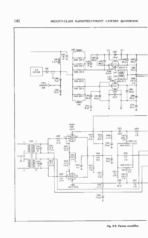
142 SECOND-CLASS RADIOTELEPHONE LICENSE HANDBOOK
4
0405
TRFQ MONITOR
3401
7
C44I 7500 T
R4I1 27K 112 W
9 8
C R412 E 4221 100 27 K 112 W
5438
10K 112 W
C412
CAW 390 pF
C410 C403 .05 ..,.. 390 pf PF
.05 e C404 0405 390 pF 390 pF
R402 220 0
Ve• '1 R403 220 C406
1402 390 PI
0413 .050F I
FRONT 5403 12857
7 3
C407 390 PF
V401
RIGHT 1411 4-400
15.I40T12 1412 IèM R4(03 4-430 8455 21 0 210
C415
.05pF
2 W
C4013 390 pF
0409 390 pF
C414 .05pF I
CO27 12420
5439
R413 112 W 10
R414 10 1,2 W
10 K I/2 W 3
R446 470 Q .2 W
8415i R415 3K) 15K, 25W IOW'
C423 1 pF T R417
15 Ke 5W
p416
5 W 20 K
9419 15 K IOW
R456 . 4.1 K
C443 750 pF
C424 .1-10 ufT
.050F I I K R422N 2W 220K 2W
8424 2 W 10 K
MOD BIAS L.
9426
2K 5 W
MOD BIAS R
R425 I 10 K R427 2 W 34 0423 e ow 221$
2
C428 R42I
5404 128Y7 REAR
0457 4.7 K
ft C 1 K .050F 2 W
C444 750 of'
Fig. 5-9. Power amplifier

RADIO BROADCASTING 143
C4I1
.05117 -71—
C416 1406 was
C417 0-500
CI474 -r TOP
C420 PA TUNE FOP
4 A R428 I meg
9429 I meg
9430 meg
9431 I meg
C429 ZOO pf
C430 200 pf I
C425 C435 ICOO
200 pf I pF
C432 200 pf
R436 22 K 2 W
9437 22 K 2 W
C437 2001
1.
RIGHI 9406 4-400
o 150 -150
9432 C436 200 pr -r I meg I me9
R440 1 s
9433 C435_L 200 pF I R441 I, meg I meg
R434 C434 R442 limyeg 1 meg 200 pF
9435 C433 9443
I me g ?CC per r R444
110 K 2 W
9453 5 K W
10501
j R410 1405 25 K Q
r.80PH f50W ....
°711 s2 .005
Off
13.6)9 47 Q
M501
OUTPUT
0409 J R450 IO7I 10 S? 2 W 12W
POWER
OUTPUT R448
vas. soy% 9407 10KP
10K 100W 25 IN
12
19300 13
T8304-12
C503 01
M503
PA PLATE
R445 1.20 2 W
HIGH VOLTAGE
o •3000
METER
lL 12 405 .AMP
C502 1 .01 'FT
and modulator schematic

144 SECOND-CLASS RADIOTELEPHONE LICENSE HANDBOOK
Fig. 1.10. An ail% frequency and modulation monitor.
Courtesy TFT, Inc.
reduction. The frequency response is -±-1 dB between 20 to 16,000 Hz; distortion is less than 1.5% at 95% modulation. Frequency stability is at least -±2 Hz with a rated carrier shift of 3% or less. The row of meters along the top from left to right are multimeter, pa
plate current, and pa plate voltage, respectively. Below the top row of meters is the rf line current meter. The two controls are pa Load and pa Tune. At the top right center are the filament and plate power switches.
Below are the filament and hum-balance controls for the power sup-plies. The transistor exciter panel includes two controls. One regulates the rf drive to the vacuum-tube rf power amplifier, which determines the power output of the transmitter, and a switch that permits the selection of one of two crystal oscillators.
Transistors are used in each stage of the transmitter up to the final rf power amplifier. There are five separate silicon-diode solid-state power supplies. Two are used by the transistor rf exciter, and there are separate bias, screen-grid voltage and plate-voltage supplies for the vacuum-tube rf power amplifier. The general arrangement of the trans-
e
Courtesy Moseley Assoc,ates
Fig. 5-11. Remote-control panel.

RADIO BROADCASTING
MULTIMETER
PLATE VOUS
PLATE CURRENT F IL OFF
S
/
1 • - 11 op a, i PLATE ON
, i ' •lrlPLATE OFF
145
RF LINE CURRENT
PLATE L0i,DING CONTROL
PLATE TUNE CONTROL
POWER CONTROL
OSC ILLATOR CHANGE-OVER SW
MULT IMETER
POWER CHANGE SW
FIL ADJUST
F IL VOLTMETER ADJUST
›,› HUM BALANCE CONTROL
LOW-POWER BIAS CONTROL
HIGH-POWER BIAS CONTROL
Courtesy Gates Radio Co.
Fig. 5.12. Vanguard II transmitter.

Fig. 5-13. Partial schematic of a solid-state transmitter.

RADIO BROADCASTING 147
mitter including some individual circuit schematics is given in Fig. 5-13. The three major divisions of the transmitter can be better seen in
Fig. 5-14. The power transformers, chokes, capacitors, relays, control components, and the blower for air-cooling the power tube are mounted at the bottom of the transmitter. At the center is the transmitter exciter which has been made readily accessible for maintenance and, if neces-sary, for complete removal. The top part of the transmitter houses the rf power amplifier stage; the anode connection to the power tube can be seen at the left. The transistor crystal oscillator is shown at the upper-left corner of
Fig. 5-13. There are two such oscillators and associated amplifier mounted in a thermostatically controlled oven. A Pierce-type crystal
Fig. 5-14. Rear view of Vanguard II transmitter.
Courtesy Gates Radio Co.

148 SECOND-CLASS RADIOTELEPHONE LICENSE HANDBOOK
oscillator is used. This stage is followed by a common-emitter buffer amplifier. Capacitor CI is used to precisely set the crystal frequency. There are no tuned circuits associated with the crystal oscillator (Q1) and its buffer stage (Q2). In fact, the first resonant circuit encountered in the transmitter is in the modulated stage. A second identical oscil-lator is shown as a block in Fig. 5-13, the oscillator units are selected by completing their respective circuits to ground through switch Si.
For transmitter operation between 1000 to 1600 kHz, the output of the crystal circuit is supplied directly to a two-stage resistance-coupled amplifier. If operation is in the frequency range of 540- to 990-kHz, the output of the crystal circuit is supplied to a transistorized binary di-vider that reduces the frequency by a factor of 2. An output from the oscillator buffer stage is also supplied to a frequency monitor amplifier. This transistor amplifier builds up the level of the signal required to drive the station frequency meter. The two-stage resistance-coupled amplifier employs no resonant cir-
cuits. It operates as a straight-through amplifier taking advantage of the high-frequency capabilities of a transistor when used in a resist-ance-coupled circuit. It is apparent that solid-state circuitry has made a revolutionary impact on the design of broadcast transmitters and broadcast equipment. Certainly this transmitter represents a substan-tial departure from the basic concepts of broadcast-transmitter design. Another example is the diode in the transmitter modulator. A two-stage transistorized audio amplifier (bottom left of schematic
Fig. 5-13) builds up the program signal to the level required by the diode modulator for linear modulation of the carrier. The input stage of the audio amplifier is a common-emitter circuit that uses base-divider bias (resistors R7 and R8) and emitter operating-point stabili-zation (resistors R10 and R11 and capacitor C14). Degenerative ac stabilization is provided by the unbypassed resistor RIO. The second stage ( Q4) of the audio amplifier is an emitter-follower circuit. It pro-vides a high input impedance, and, therefore, maximum voltage gain can be derived from the first stage. At the same time, Q4 has a very low impedance output and acts as a low-impedance source for the modulating wave applied to the crystal modulator ( D1 ). A diode modulator operates as a linear modulating circuit when
the applied signals are of adequate level and of the proper ratio. In the diode modulator ( D1 ) of Fig. 5-13 the ratio is approximately 3 to 1, or 30 volts of rf carrier input and 10 volts of modulating signal input. A mixing process produces the modulation envelope. If only the rf signal were applied to the diode modulator, the diode current would follow the positive anode alternations. This pulsating current would be filtered out by the output resonant circuit to reconstruct the original rf sine wave. However, when an audio sine wave is applied to the input of the modulator along with the rf wave, a combining action takes place and the peak amplitudes of the peak diode current pulsa-tions depend on the net diode anode voltage at the crest of each radio-frequency cycle. This diode voltage varies up and down with the modulating wave. As a result, the peak diode current varies corre-sondingly as in Fig. 5-15. The resonant circuit (L1, C9, and C10) be-

RADIO BROADCASTING 149
cause of its energy storing ability reconstructs the opposite alternation of the output voltage variation, forming the familiar a-m modulation envelope. The input is the simple combining of two separate signals. However,
the output wave results from nonlinear mixing or heterodyning and is composed of three radio-frequency components—the carrier frequency plus two side frequencies.
It is significant that the modulation of the transmitter has occurred at a very low power level. If the modulation envelope is not to be dis-torted, all following rf amplifiers must be operated as linear class-AB or class-B rf amplifiers.
RF CARRIER INPUT TO DIODE
,-
DIODE CURRENT OUTPUT
MODULAT ION S IGNA.. OUTPUT OF LI. C9. CIO, TANK CIRCUIT
AUDIO PROGRAM SIGNAI
-
,
-
,
- - -
, *.el ....
„
eig. 5-15. Diode and diode-output tank-circuit waveform.
The two final stages of the exciter are the linear rf amplifiers in the lower right side of the schematic ( Fig. 5-13). The input stage ( Q5 and Q6) consists of two transistors in parallel. Base-divider bias is aug-mented with a thermistor (R17) that compensates for changes in the conductance of the emitter junctions of Q5 and Q6 with temperature. A pi-network resonant circuit (C18, L2, C19) is employed, providing im-pedance match between the Q5-Q6 output and the input of the final transistor rf amplifier. The final rf stage (Q7) is operated near class-B. However, an adjustable emitter resistor (R24) is used to adjust the power output of the exciter and the drive to the vacuum-tube power amplifier. This control (R24) can be adjusted from the front panel of

150 SECOND-CLASS RADIOTELEPHONE LICENSE HANDBOOK
the transistor exciter. A pi-network (C23, L5, and C24) is used to match the output of transistor Q7 to the input of the vacuum-tube power amplifier.
In the transmitter, feedback is used to stabilize the operating pa-rameters of the transmitter and hold the distortion at a low level. There is a feedback path between the vacuum-tube rf amplifier (VI) and the input to the audio amplifier (Q3) of the exciter. An associated varia-ble control (R26) is used to set the level of the feedback, which is usually 8 dB. The output of the transistor exciter is supplied through a parasitic
choke (L6) and capacitor (C26) to the control grid of the rf power amplifier (Fig. 5-16). Inasmuch as the rf input signal has an a-m mod-ulated envelope, stage VI must be operated as a linear amplifier. External bias is supplied by a separate power supply and is applied to the control grid via the rf choke (L8). The positions of the three key meters of the transmitter, antenna
current ( M3), plate voltage (M2) and plate current (M1) are shown on the schematic (Fig. 5-16). Potentiometer R29 is used for hum bal-ancing in the filament circuit to prevent 60-hertz modulation of the carrier. The multimeter (M4) can be used to measure the following parameters: collector current of the final transistor stage (Q7) of the exciter, the grid bias ( —E,.), the filament voltage (Fil), the screen-grid voltage (E„g), and the screen-grid current (I„g) of the power-amplifier stage ( VI ). A pi-T network (L11, C35, C36, L12, C37, L13, and C38) is used
to match and transfer power to the antenna system. Inductors L11 (PA tuning) and L13 (PA loading) are continuously variable, and the input-loading coil (L12) uses a shorting tap. Inductor L11 is used to bring the tuned circuit into resonance, while inductor L13 controls the antenna loading and the dc plate current at resonance. If it is not pos-sible to establish the required plate current at resonance, correction can be made by moving the tap on inductor L12.
Capacitor C29 and inductor L9 provide a form of bridge neutraliza-tion. Energy for feedback is obtained by mounting a small fixed plate near the air chimney that surrounds the tube in its mounted position. The capacitance removes energy from the anode of the tube and it feeds it back as a neutralization component to the control grid. A similar takeoff arrangement is used to derive the audio feedback
for the transmitter. In this case the energy picked up by the fixed plate near the air chimney is supplied to a diode detector ( D2). The audio output is coupled back to the secondary of the audio input trans-former ( T1 ) of the exciter.
5-4. MAJOR UNITS OF ANTENNA SYSTEMS
A variety of units are associated with the antenna system of the a-m broadcast station, as shown in Figs. 5-17 and 5-18. The modulated rf signal is usually conveyed over a coaxial transmission line to an an-tenna tuning box, the function of which is to tune the antenna to proper resonance and match the transmission line to the antenna (see

9NILSVDCIVO}ill OICIV11
CJ1

152 SECOND-CLASS RADIOTELEPHONE LICENSE HANDBOOK
Fig. 5-17). Often a remote antenna-current meter is associated with the antenna tuning arrangement. Although the pickup device is part of the antenna-tuning unit, the recording meter is often mounted at the transmitter. This reading gives an excellent indication of the operating conditions of the transmission line and antenna system; it soon indi-cates any line and antenna-system defect or a decrease in the power output of the transmitter. The antenna must have suitable lightning protection. Usually it is
in the form of a spark gap and a retarding inductor. Also, the power line to the obstruction and beacon lights must be isolated properly in order not to disturb the radio-frequency characteristics of the antenna. These accessories must be protected from lightning damage as much as possible.
RIME .10.4 (UMW MOIR
SM. CAP
PA Ix TO 4110.13
•amoGélTiNt CM. ,
1-4.10
Fig. 5-17. The major units of antenna systems.
Additional units are required for a directional-antenna system. The arrangement in Fig. 5-18 is typical. The directional-antenna pattern is obtained by proper spacing of the antenna towers and by correct phas-ing between the existing radio-frequency currents. Correct radio-fre-quency current relationships are established by a phasing unit gener-ally mounted near the transmitter. These phase currents are conveyed on separate coaxial lines to the respective antenna towers and their associated tuning boxes. A sampling loop, mounted on each radiator, picks up a small amount
of rf current and, through its own line, supplies signal to a phase moni-tor in the transmitter building. The function of the phase monitor is to evaluate the incoming current components from the sampling loops, and to indicate whether correct relationships have been established at the antennas. The antenna boxes in Fig. 5-18 also show the chokes which isolate the lighting system from the radio-frequency energy, and also the unit that flashes the beacon light on and off in accordance with FCC requirements.

TRANSMITTER Bu (HNC
TRANSMITTER
TRANSMITTER
TO BE SELECTED
IN ACCORDANCE ITH AUTHORIZED
OPERATING POWER OR STAT ION
PHASING BRANCHING 501.41PMENT
PHASE MONITOR
COAX IAL TRANSMITS ION LINE
COAXIAL SA PL INC LINE
L GAIN INC CHOKE F LA SAL R
- SAMPLING
LOOP
COAX IAL SAMPLING LINE
TO BEACON
TO SIDE LIGHTS
ANTENNA TUNING UNIT
COAX IAL TRANSMISSION LINE
ISOLA T ION COIL
ANTENNA TUNING HOUSE NO I
-i IGHTNING L CHOKE
COAX IAL SA PL INC I IN(
FLASHER
COAXIAL SAMPL ING
TO BEACON
TO SIDE LIGHTS
L IN(
L. r0 GROUND SYSTEM
H.- SAMPLING LOOP
COAX IAL SAMPLING
LINE
ANTENNA TUNING UNIT
ISOLATION COIL
ANTENNA TUN MG HOUSE NO 2
COAXIAL SAMPLING L WE
L/ TO GROUND SYSTEM
9NIISVDGVOIIH ORIVU
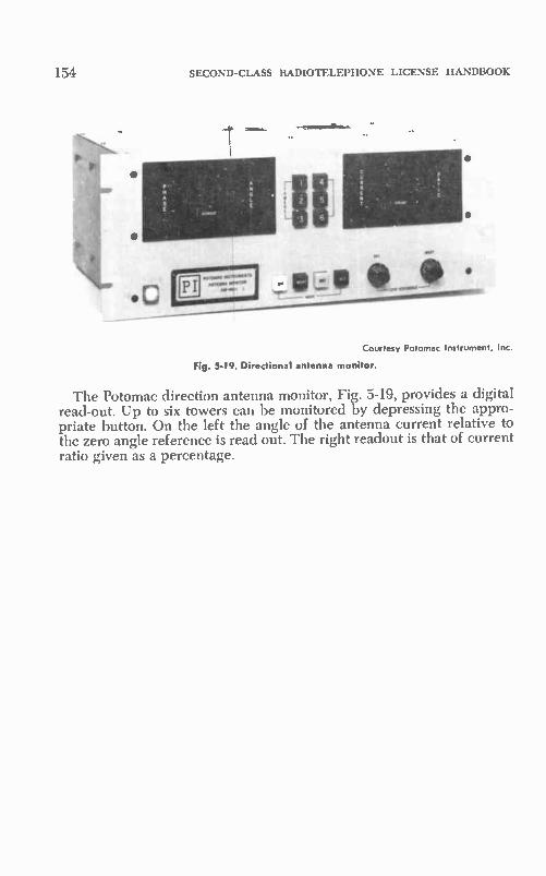
154
1 ell" 1111111 .0 o LA O. le
SECOND-CLASS RADIOTELEPHONE LICENSE HANDBOOK
Courtesy Potomac Instrument, Inc.
Fig. 5-19. Directional antenna monitor.
The Potomac direction antenna monitor, Fig. 5-19, provides a digital read-out. Up to six towers can be monitored by depressing the appro-priate button. On the left the angle of the antenna current relative to the zero angle reference is read out. The right readout is that of current ratio given as a percentage.

CHAPTER 6
Elements I and II Basic law and
Operating Practices
The radio spectrum, being finite, must be regulated to provide space for the many services available. Frequen-cies must be allocated in segments ac-cording to the services each sector can best render. Rules of procedure must be established, and assignment and techni-cal regulations enf3rced if the univer-sal benefits of communications are to be derived for all.
In the United States the regulatory agency is the Federal Communications Commission (FCC), established under the Communications Act of 1934. Im-portant extracts of this act are pre-sented in the appendices as well as ex-tracts from the Rules and Regulations. The United States is also bound by cer-tain international agreements, because radio waves do not observe boundaries in their travels. Some extracts of the International Radio Regulations are given.
All the extracts in the Appendices are of significance in preparing for the com-mercial radio operator's examinations. More than just a preparation for a test, they emphasize the responsibilities of a license holder. As one, it is assumed you know and will abide by the rules and regulations established for the radio service or services with which you are concerned.
Copies of the rules and regulations for the various radio services are avail-able on subscription from the U.S. Government Printing Office, Washing-ton 25, D.C. If your interest is in two-way radio, you should subscribe to Vol-ume V, which includes Aviation, Public Safety, Industrial, and Land-Transporta-
tion Radio Ser‘ ices. If you have an addi-tional interest in Citizens band radio, Volume VI is available. For the Mari-time Services, there is Volume IV.
Elements I and II are about the basic laws and operating practices. The an-swers given in this chapter to the test questions for Elements I and II are short, concise, and yet adequate to fit in with the direct answers associated with a multiple-choice type of examina-tion. After many answers, the specific laws and regulations given in the ap-pendices are referred to by the abbre-viations SEC for Communications Act, R.R. for Rules and Regulations, and IRT for International Radio Regula-tions. Read the specific laws carefully. This step will improve your under-standing and help you better retain the information you need to know.
Notice that safety and distress laws and procedures are stressed. You may never use this information while you are a license holder, but if a distress situation does arise in which you must play a part, there is no more important knowledge. The test questions for Elements I
and H were taken from the latest sup-plement Study Cuide and Reference Material for Commercial Operator Ex-aminations prepared by the Federal Communications Commission. They are representative of the scope of the ques-tions in the commercial radio-operator examinations.
At the conclusion of this chapter (and also chapters 7 through 14) there is a 25-question self-test. When you com-plete the work for each chapter take the
155

156 SECOND-CLASS RADIOTELEPHONE LICENSE HANDBOOK
test without referring to the chapter ma-terial. The answers to the tests begin on page 341. If your grade is 75% or better you have done very well in your coverage of the chapter material. Find your errors and review the chap-ter carefully before trying the test again. The test is an excellent review and
should not be considered solely as a means of testing your memory. Under-stand the logic of each right answer and the manner in which it consoli-dates useful information. Of equal im-portance is the careful consideration of each wrong answer. Some are quite ob-vious while others make you think a bit before the mistake is apparent. For best use of the test material study both the right and wrong answers.
6-1. ELEMENT I-BASIC LAW
I-I. Where and how is an operator li-cense or permit obtained?—Request an application form and examination schedule from the nearest FCC field office. Submit the application in the prescribed form, including all subsidi-ary forms and documents accompanied by the prescribed fee, properly com-pleted and signed, in person or by mail, to the office of your choice (usually the closest one). This office will make the final arrangements. (R.R.13.11a.)
I-2. When a licensee qualifies for a higher grade of FCC license or permit, what happens to the lesser grade li-cense?—The license or permit held will be cancelled upon issuance of the new license. ( R.R.13.26. )
I-3. Who may apply for an FCC li-cense?—Normally, commercial licenses are issued only to citizens and other nationals of the United States. An ex-ception is alien pilots certified by FAA. ( R.R. 13.5A.)
I-4. If a license or permit is lost, what action must be taken by the operator? —The commission must be notified im-mediately, and a properly executed ap-plication for a duplicate should be sub-mitted. A statement must be included regarding the circumstances involved in the loss of the license. The operator must exhibit in lieu of the original document a signed copy of the sub-
mitted application. (R.R. 13.71 and 13.72.)
I-5. What is the usual license term for radio operators?—Five years. ( R.R.-13.4a. )
1-6. What government agency inspects radio stations in the United States?— The Federal Communications Commis-sion. This applies to all types of sta-tions. ( SEC 303n.)
I-7. When may a license be renewed? —The application may be filed at any time during the final year of the license term or during a one-year period after the date of the expiration of the license. During this one-year period of grace any prior license is not valid. (R.R. 13.11a.)
I-8. Who keeps the station log?—Per-son or persons competent to do so hav-ing actual knowledge of the facts re-quired. They shall sign the appropriate log when starting duty and again when going off duty. ( R.R. 73.111.)
I-9. Who corrects errors in the station log?—Only the person originating the entry. ( R.R. 73.111.)
I-10. How may errors in the station log be corrected?—The person originat-ing the entry shall strike out the erro-neous portion, initial the correction made, and indicate the date of correc-tion. ( R.R. 73.111.)
I-11. Under what conditions may mes-sages be rebroadcast?—Only by the ex-press authority of the originating sta-tion. (SEC 325a. )
I-12. What messages and signals may not be transmitted?—Unnecessary, un-identified, or • superfluous communica-tions; obscenity, indecency, profanity, and false signals using any call or sig-nal which has not been assigned by proper authority to the radio station concerned. (R.R.13.66, 13.67 and 13.68.)
I-13. May an operator deliberately in-terfere with any communication or sig-nal?—No. ( R.R.13.69.)
I-14. What type of communication has top priority in the mobile service?—Dis-tress calls, distress messages, and dis-tress traffic. Next in priority are urgency
ELEMENTS I AND II BASIC LAW AND OPERATING PRACTICES
and then safety signals. If an operator is told his station is interfering with a distress message he must stop transmit-ting immediately. ( ART. 37.)
1-15. What are the grounds for suspen-sion of an operator's license?—Violation of any provision of any act, treaty, or convention binding on the United States; failure to carry out a lawful or-der of the master or person lawfully in charge of ship or aircraft on which he is employed; damaging or permitting the damage of any radio apparatus or installation; transmission of profane or obscene language, false or deceptive signals; use of false call signs or letters which have not been assigned to the station in operation; willful or malicious interference with other radio-eornmuni-cations or frequencies; obtaining, at-tempting to obtain or assisting another to obtain or attempt to obtain an op-erator's license by fraudulent means. (SEC. 303m.)
1-16. When may an operator divulge the contents of an intercepted message? —He may divulge the contents of any radio-communications broadcast or transmission by others for use of the general public or relating to ships in distress. (SEC. 605.)
I-17. If a licensee is notified that he has violated an FCC rule or provision of the Communications Act of 1934, what must he do?—Ile must reply within ten days to the office of the commission originating the official no-tice. The answer tc each notice shall be complete in itself and shall not be ab-breviated by reference to other commu-nications or other notices. In every instance the answer shall contain a statement of the action taken to correct the condition or omission complained of and to preclude its recurrence. Informa-tion concerning equipment of concern, and name and license number of op-erator in charge. ( R.R. 1.89.)
I-18. If a licensee receives a notice of suspension of his license, what must he do?—No order of suspension of any op-erator's license shall take effect until 15 days after a notice in writing of the cause has been given to the operator. He may make written application to the commission at any time within said 15 days for a hearing on such order. If after a hearing a license is ordered sus-pended, the operator shall send his li-
157
cense to the office of the commission in Washington, D.C. on or before the ef-fective date of such order. ( R.R. 1.85.)
1-19. What are the penalties provided for violation of the provisions of the Communications Act of 1934 or a rule of the FCC?—Penalties for violation of the Act provide for a fine of not more than $10,000.00 or imprisonment for a term not exceeding one year, or both. The penalty provided for violation of FCC rules is a fine of not more than five hundred dollars for every day dur-ing which said offense occurs. ( SEC. 501 and 502.)
1-20. Define harmful interference.— Any emission, radiation, or induction which endangers the function of a ra-dionavigation service or other station services, or seriously degrades, ob-structs, or repeatedly interrupts a ra-diocommunications service operating in accordance with the regulations.
6-2. ELEMENT II-BASIC OPERATING PRACTICE
Each radiotelephone operator should know and abide by the rules and ac-cepted procedures of operation. Cour-tesy and consideration are two very important factors in minimizing un-necessary interference and maintaining reliable communications on active chan-nels. The second-class radiotelephone license holder should be an example to operators of lower grades, and he should do everything possible to en-courage proper operations in the service or services with which he is con-nected. A fine summary of radiotelephone op-
erating practice, recommended by the FCC, follows: A licensed radio operator should re-
member that the station he desires to operate should be licensed by the Fed-eral Communications Commission. In order to prevent interference and to give others an opportunity to use the airways he should avoid unnecessary calls and communications by radio. He should remember that radio signals nor-mally travel outward from the trans-mitting station in many directions and can be intercepted by unauthorized persons.
Before making a radio call the oper-ator should listen on the communica-tions channel to insure that interference will not be caused to communications

158 SECOND-CLASS RADIOTELEPHONE LICENSE HANDBOOK
which may be already in progress. At all times in radiocommunications the operator should be courteous.
Station identification should be made clearly and distinctly so that unneces-sary repetition of call letters is avoided and to enable other stations to clearly identify all calls. An operator normally exhibits his au-
thority to operate a station by posting a valid operator license or permit at the transmitter control point.
While a radio transmitter is in a pub-lic place it should at all times be either attended by or supervised by a licensed operator, or the transmitter should be made inaccessible to unauthorized per-sons. A radio transmitter should not be on
the air except when signals are being transmitted. The operator of a radiotele-phone station should not press the push-to-talk button except when he intends to speak into the microphone. Radiation from a transmitter may cause interfer-ence even when voice is not trans-mitted. When radiocommunications at a sta-
tion are unreliable or disrupted due to static or fading, it is not a good prac-tice for the operator to continuously call other stations in attempting to make contact because his calls may cause in-terference to other stations that are not experiencing static or fading. A radiotelephone operator should
make an effort to train his voice for most effective radiocommunication. His voice should he loud enough to be dis-tinctly heard by the receiving operator, and it should not be too loud since it may become distorted and difficult to understand at the receiving station. He should articulate his words and avoid speaking in a monotone as much as possible. The working distance range of the transmitter is affected to some ex-tent by the loudness of the speaker's voice; if the voice is too low, the maxi-mum distance range of the transmitter cannot be attained; and if the voice is too loud, the distance range may be re-duced to zero due to the signals becom-ing distorted beyond intelligibility. In noisy locations the operator sometimes cups his hands over the microphone to exclude extraneous noise. Normally, the microphone is held from 2 to 6 inches from the operator's lips.
It is important in radiotelephone communications that operators use fa-miliar and well-known words and phrases in order to insure accuracy and
save time from undue repetition of words. Some radio companies, services, networks, associations, etc., select and adopt standard procedure words and phrases for expediting and clarifying radiotelephone conversations. For ex-ample, in some services, "Roger" means "I have received all of your last trans-mission;" "Wilco" means "Your last message received, understood, and will be complied with;" "Out" or "Clear" means "This conversation is ended and no response is expected;" "Over" means "My transmission is ended, and I ex-pect a response from you;" "Speak slower" means "Speak slowly;" "Say again" means "Repeat" and "Words twice" means "Give every phrase twice."
Often in radiotelephone communica-tions a "phonetic alphabet" or word list is useful in identifying letters or words that may sound like other letters or words of different meaning. For exam-ple "group" may sound like "scoop," or "bridge" may sound like "ridge." A phonetic alphabet or word list consists of a list of 26 words each word with a different letter for identifying that par-ticular letter. If the letters in "Group" are represented in a phonetic alphabet by George, Roger, Oboe, Uncle and Peter, the word "Group" is transmitted as "Group, G as in George, R as in Roger, O as in Oboe, U as in Uncle, P as in Peter."
In making a call by radio, the call sign or name of the called station is generally given 3 times followed by the call letters of the calling station given 3 times.
In testing a radiotelephone transmit-ter the operator should clearly indicate that he is testing, and the station call sign or name of the station, as required by the rules, should be clearly given. Tests should be as brief as possible.
If a radio station is used only for occasional calls, it is a good practice to test the station regularly. Regular tests may reveal defects or faults which, if corrected immediately, may prevent de-lays when communications are neces-sary. Caution should be observed by persons testing a station to make cer-tain their test message will not inter-fere with other communications in progress on the same channel. Techni-cal repairs or adjustments to radiotele-phone communication stations are made only by or under the immediate super-vision and responsibility of operators holding first- or second-class licenses.

ELEMENTS I AND II BASIC LAW AND OPERATING PRACTICES
When a licensed operator in charge of a radiotelephone station permits an-other person to use the microphone and talk over the facilities of the station, he should remember that he continues to bear responsibility for the proper opera-tion of the station.
If an operator wishes to determine the specifications for obstruction mark-ing and lighting of antenna towers, he should look in Part 17 of the Rules and Regulations of the FCC. If he wishes to determine the specifications for a par-ticular station, he should examine the station authorization issued by the Com-mission.
6-24. General (Series "0")
II-1. What should an operator do when he leaves a transmitter unat-tended?—The transmitter should be made inaccessible to unauthorized per-sons.
II-2. What are the meanings of clear, out, roger, words twice, repeat and break?—Refer to the appropriate words in the summary. "Repeat" means to transmit a message or section of mes-sage again to make certain it has been copied correctly.
"Over" means "My transmission is ended and I expect a reply from you." "Words twice" means "Give every
phrase twice."
II-3. How should a microphone be treated when used in noisy locations?— The operator can cup his hand over the microphone to exclude extraneous noise.
II-4. What may happen to the received signal when an operator has shouted into a microphone?—The range of the transmission may be decreased because the signal may become distorted beyond intelligibility because of overmodula-tion.
II-5. Why should radio transmitters be off when signals are not being trans-mitted?—Radiation from the transmit-ter may cause interference even though voice or other information is not being transmitted.
11-6. Why should an operator use well-known words and phrases?—It is ad-visable to insure accuracy and save time from undue repetition of words.
159
II-7. Why is the station call sign trans-mitted?—So that other stations may clearly identify all calls. Call signs must also be given at prescribed times ac-cording to FCC rules related to the par-ticular radio service.
11-8. Where does an operator find specifications for obstruction marking and lighting where required for the antenna towers of a particular radio station?—Data may be found in Part 17 of the FCC Rules and Regulations. Lights should be inspected every 24 hours. In case of failure of lights the FAA Airways Communication Station must be notified if repair is not possible within 30 minutes.
11-9. What should an operator do if he hears profanity being used at his sta-tion?—He should take steps to prevent the profanity from going out on the air.
II-10. When may an operator use a station without regard to certain pro-visions of the station's license?—During a period of emergency during which normal communications are disrupted. ( R.R. 2.405. )
II-11. Who bears the responsibility if an operator permits an unlicensed per-son to speak over his station?—The li-censed operator continues to bear re-sponsibility for the proper operation of the station.
II-12. What is meant by a phonetic alphabet in radiotelephone communi-cations?—It is helpful in identifying let-ters or words that have different mean-ings. An example is given in the sum-mary presented at the beginning of Section 6-2 in Chapter 6.
II-13. How does the licensed operator of a station normally exhibit his au-thority to operate the station?—A valid operator's license must be displayed at the transmitter control point.
II-14. What precautions should be ob-served in testing a station on the air?— Be certain testing does not interfere with other communications in progress on the same channel. Clearly indicate that you are testing. Technical repairs and adjustments are the responsibility of a first- or second-class license holder.
In testing a radiotelephone transmit-ter the operator should clearly indicate that he is testing, and the station call

160 SECOND-CLASS RADIOTELEPHONE LICENSE HANDBOOK
sign or name of the station, as required by the rules, should be clearly given. Tests should be as brief as possible.
6-2-2. Maritime (Series "M")
II-Ml. What is the importance of the frequency 2182kHz?—This frequency is the international distress frequency for radiotelephony. It can be used by ships, aircraft, and survival craft stations using frequencies in the 1605-3500 kilohertz spectrum. This frequency is also the international general radiotelephone calling frequency for the maritime mo-bile service. It may be used by ship stations and aircraft stations operating in the maritime mobile service. (R.R. 83.352, 83.353a.)
II-M2. Describe completely what ac-tion should be taken by a radio oper-ator who hears a distress message; a safety message.—If in the vicinity, beyond any possible doubt, he should immediately acknowledge receipt. How-ever, in areas where reliable communi-cation with one or more coast stations are practicable, a ship station may defer this acknowledgment for a short inter-val so that a coast station may acknowl-edge receipt. If not in the vicinity, beyond any possible doubt, the operator shall allow a short interval of time to elapse before acknowledging receipt of the message, in order to permit stations nearer to the mobile station in distress to acknowledge receipt of the message without interference. The acknowledgment of the receipt
of a distress message is then made ac-cording to established radiotelegraph and radiotelephone operation proce-dures. On order of the master or person responsible for the ship, the operator shall supply the name of his ship and position and the speed at which it is proceeding toward, and the approximate time it will take to reach, the station in distress. However, it is important that the station shall be certain that it will not interfere with the emission of other stations better situated to render im-mediate assistance to the station in distress. A station may relay the distress mes-
sage in any of the following cases: (1) station in distress not able to transmit a distress message, (2) when a responsi-ble person considers that further help is necessary, (3) when the station is not in position to render assistance but has heard that the distress message has not
been acknowledged. Read R.R. 83.240, 83.241, and 83.242 carefully: A safety signal indicates that the sta-
tion is about to transmit a message con-cerning the safety of navigation or giv-ing important meterological warning. Listen until the message is concluded. Such a station should be given its proper priority of transmission accord-ing to ART. 37. (R.R. 83.239, 83.240, 83.241, 83.242, 83.249 and ART. 37.)
II-M3. What information must be con-tained in distress messages? What pro-cedure should be followed by a radio operator in sending a distress message? What is a good choice of words to be used in sending a distress message?— Distress messages should contain the following information:
a. Distress call b. Name of ship c. Geographical position d. Nature of distress e. What kind of assistance is needed f. Any additional information that
will help in the rescue, such as type of ship, color, length, etc.
The international radiotelegraph dis-tress signal is SOS (... - - - ...); the international radiotelephone distress sig-nal is the word "MAYDAY." The radio-telephone distress procedure shall con-sist of a radiotelephone alarm signal whenever possible, the distress call, and the distress message. This distress trans-mission shall be made slowly and dis-tinctly, each word being clearly pro-nounced. Words should be simple and to the point. On advisement it may be necessary to transmit suitable signals followed by a call sign or name to per-mit direction-finding stations to deter-mine position. The distress message can be repeated
at intervals until an answer is received. If there are no answers the message may be repeated on any other available frequency on which attention might be attracted.
It is important that you go over each rule and regulation very carefully, word by word. (R.R. 83.234 and 83.238.)
II-M4. What are the requirements for keeping watch on 2182 kHz? If a radio operator is required to stand watch on an international distress frequency, when may he stop listening?—Each sta-tion on board a ship navigating the Great Lakes and licensed to transmit on telephony within the band 1605—

ELEMENTS I AND II BASIC LAW AND OPERATING PRACTICES
3500 kHz shall maintain an efficient watch on 2182 kHz, whenever the sta-tion is not being used for transmission on that channel or for communications on other radio channels. Except for sta-tions on board vessels required by law to be fitted with radiotelegraph equip-ment, each ship station licensed to transmit telephony within the band 1605-3500 kHz shall maintain an effi-cient 2182 kHz watch whenever such station is not being used for transmis-sion on that channel or for communi-cation on other radio channels. (R.R. 83.223.)
II-M5. Under what circumstances may a coast station contact a land station by radio?—To facilitate the transmission or reception of safety communications to or from a ship or aircraft station. ( R.R. 81.302a2.)
II-M6. What do distress, safety, and urgency signals indicate? What are the international urgency, safety, and dis-tress signals? In the case of a mobile radio station in distress, what station is responsble for the control of distress message traffic?—A distress signal indi-cates that a mobile station is threatened by grave and imminent danger and re-quests immediate assistance. The ur-gency signal indicates that the calling station has a very urgent message to transmit concerning the safety of a ship, aircraft, or other vehicle, or the safety of a person. The safety signal indicates that the station is about to transmit a message concerning the safety of navi-gation or giving important meteorologi-cal warnings. These signals are as fol-lows:
Distress Urgency Safety
Radio- Radio-telegraph telephone
SOS MAYDAY XXX PAN T T T SECURITY
Whenever it is possible the mobile sta-tion in distress is responsible for the controls of distress message traffic. ( R.R. 83.234 through 83.249.)
H-M7. In regions of heavy traffic, why should an interval be left between ra-diotelephone calls? Why should a radio operator listen before transmitting on a shared channel? How long may a radio operator in the mobile service continue attempting to contact a station which
161
does not answer?—An interval should be left between radiotelephone calls to per-mit the shared use of the channel. An operator should listen before transmit-ting on a shared channel to make cer-tain he does not interfere with commu-nications in progress. A call shall not continue for more than 30 seconds. If the called station does not reply, a sec-ond call should not again be made until after an interval of 2 minutes. If there is no reply to a call sent three times at intervals of 2 minutes, the calling shall cease and shall not be renewed until after an interval of 15 minutes. How-ever if there is no reason to believe that harmful interference will be caused the call sent three times at intervals of 2 minutes may he repeated after a pause of not less than 3 minutes. When propa-gation conditions are impossible and unreliable, wait until the situation im-proves. (R.R. 83.366 and Summary.)
H-M8. Why are test transmissions sent? How often should they be sent? What is the proper way to send a test mes-sage? How often should the station call sign be sent?—If the station is used at infrequent intervals, test transmissions can be sent out to ascertain if the trans-mitter continues to operate in a nor-mal manner. If the station has not been in operation, the transmitter can be checked with a test transmission ac-cording to an adopted schedule (once each 24 hours is often considered appro-priate). When tests are required, pre-cautions should he taken to prevent any emission that will cause harmful inter-ference. Radiation must be reduced to the lowest practicable value and en-tirely suppressed if possible. The li-censed operator shall listen carefully before making test emissions so as not to interfere with transmissions in prog-ress. The official call sign of the testing
station followed by the word "test" shall be announced as a warning that test emissions are to he made. If any other station transmits the word "wait," testing shall he suspended an appro-priate interval of time.
During tests the operator then an-nounces the word "testing" followed by a voice transmission test by numerical count. Test signals should be transmit-ted that do not conflict with normal op-erating signals or that will actuate auto-matic alarms. The test signal shall have a duration not exceeding ten seconds.
At the conclusion of the test a voice

162 SECOND-CLASS RADIOTELEPHONE LICENSE HANDBOOK
announcement of the official call sign, name of the ship or station, and general location is to be made. It is customary to give the call sign three times. The test transmission shall not be repeated until at least one minute has elapsed or, in a region of heavy traffic, a period of at least five minutes shall elapse before another test transmission is made on key frequencies. (R.R. 83.365 and Sum-mary.)
H-M9. In the mobile service, why should radiotelephone messages be as brief as possible?—Transmissions should be brief to give other stations a chance to use the channel and to minimize in-terference. ( Summary.)
H-M10. What are the meanings of: clear, out, over, roger, words twice, re-peat, and break?—Refer to the operat-ing summary at the beginning of 6-2.
II-M11. Does the 1959 Geneva treaty give other countries the authority to in-spect U.S. vessels?—Yes, when the mo-bile station visits another country. The license or a copy certified by the au-thority which has issued it should be permanently exhibited in the station. (ART 21.)
II-M12. Why are call signs sent? Why should they be sent clearly and dis-tinctly?—Call signs should be sent and transmitted clearly and distinctly so that the station may be identified ex-
actly by other stations and transmission time kept to a minimum. (Summary.)
II-M13. How does the licensed oper-ator of a ship's station exhibit his au-thority to operate a station?—The origi-nal license should be exhibited at a conspicuous place at the principal loca-tion on board ship. For certain stations of portable nature and when the oper-ator holds a restricted radiotelephone operator permit, the person may have on his person either the operator license or a verification card. ( R.R. 83.165. )
H-M14. When may a code station not charge for messages it is requested to handle?—No charge shall be made for the transmission of distress messages and replies thereto in connection with situations involving the safety of life and property at sea or for any informa-tion concerning danger to navigation as designated. Except for effective tariffs on file with the commission no charge shall be made for the service of any public coast station. ( R.R. 81.179.)
H-M15. What is the difference between calling and working frequencies?—Call-ing frequencies are used for transmis-sions from a station solely to secure the attention of another station for a par-ticular purpose. A working frequency is used strictly for carrying on radio-communications other than calling by any stations using telegraphy, tele-phony, or facsimile (R.R. 83.6.)
6-3. CHAPTER 6 SELF-TEST
(Answers on page 432)
I. When a licensee qualifies for a higher grade license, the lesser grade license A. is cancelled. C. is still valid. B. must be returned to the FCC. D. may be used as a verification card.
2. When a license or permit is lost the licensee A. must notify FCC within 30 days. C. may not operate. B. must submit application for a D. is dropped to a lower grade.
duplicate immediately.
3. Radio station inspection is done by the A. FBI. C. FAA. B. FCC. D. CIA.
4. Station logs are signed A. by FCC inspectors. C. at local sunrise. B. when new equipment is in- D. when starting and going off duty.
stalled.

ELEMENTS I AND II BASIC LAW AND OPERATING PRACTICES
5. An error in the log is corrected by A. erasure and dating. B. erasure and signing by the per-
son correcting the log.
6. Profanity on the air A. is legal. B. is a violation of FCC rules and
regulations.
7. The urgency signal has A. more priority than a distress
signal. B. more priority than a security
signal.
8. An operator may divulge the contents of a
C. D.
C.
D.
163
rewriting the entire page. striking, dating, and signing by the person correcting the log.
is permitted because it emphasizes a situation. must be used on the proper fre-quency.
C. less priority than a safety signal. D. a TTT radiotelegraph signal.
A. distress message. C. marine radiotelephone conversation. B. business transaction. D. commercial shipping instructions.
9. When a licensee receives a notice of suspension it shall take effect A. immediately. C. in 30 days. B. in 15 days. D. in 24 hours.
10. A spurious emission that interrupts a radiocommunication service A. is permissible at low power. C. is a strong c-w signal. B. is permissible on shared chan- D. is harmful interference.
nels.
11. "Over" means A. change over to a new frequency. B. change to another mode of
transmission.
12. Overmodulation can be caused by A. shouting into the microphone. B. operating on a wrong frequency.
13. Accuracy is improved by A. using long descriptive words
and sentences. B. talking fast.
C. D.
C. D. posting a wrong license.
C. D.
change c-w speed. my transmission is ended and a re-ply is expected.
too little modulator power.
using well-known words. shouting into the microphone.
14. Lights of an antenna tower should be inspected every A. 24 hours. C. week. B. 48 hours. D. 30 days.
15. A coast station may contact a land station A. for a friendly chat. C. to aid in
messages. D. to relay press B. to handle ship traffic.
16. During an emergency A. every station should get on the
air. B. certain provisions of a station
license need not be followed when normal communications are disrupted.
transmission of safety
traffic.
C. shout into the microphone. D. chase distress messages off your
channel.
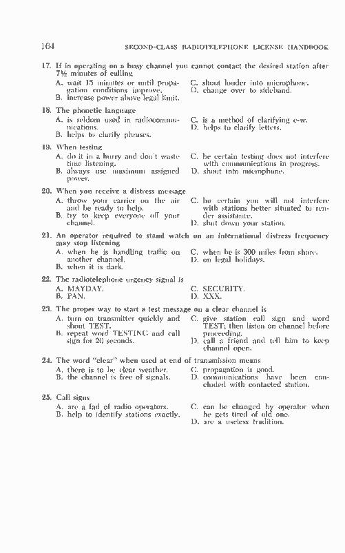
164 SECOND-CLASS RADIOTELEPHONE LICENSE HANDBOOK
17. If in operating on a busy channel you cannot contact the desired 71/2 minutes of calling A. wait 15 minutes or until propa-
gation conditions improve. B. increase power above legal limit.
18. The phonetic language A. is seldom used in radiocommu-
nications. B. helps to clarify phrases.
19. When testing A. do it in a hurry and don't waste C.
time listening. B. always use maximum assigned D.
power.
20. When you receive a distress message A. throw your carrier on the air C.
and be ready to help. B. try to keep everyone off your
channel. D.
21. An operator required to stand watch on may stop listening
C. D.
C. D.
A. when he is handling traffic on C another channel.
B. when it is dark.
22. The radiotelephone urgency signal is A. MAYDAY. B. PAN.
station after
shout louder into microphone. change over to sideband.
is a method of clarifying c-w. helps to clarify letters.
be certain testing does not interfere with communications in progress. shout into microphone.
be certain you will not interfere with stations better situated to ren-der assistance. shut down your station.
an international distress frequency
. when he is 300 miles from shore. D. on legal holidays.
C. SECURITY. D. XXX.
23. The proper way to start a test message on a clear channel is A. turn on transmitter quickly and C. give station call sign and word
shout TEST. TEST; then listen on channel before B. repeat word TESTING and call proceeding.
sign for 20 seconds. D. call a friend and tell him to keep channel open.
24. The word "clear" when used at end of transmission means A. there is to be clear weather. C. propagation is good. B. the channel is free of signals. D. communications have been con-
cluded with contacted station.
25. Call signs A. are a fad of radio operators. B. help to identify stations exactly.
C. can be changed by operator when he gets tired of old one.
D. are a useless tradition.
CHAPTER 7
Element Ill Alternating and Direct Current
This is your first set of FCC study guide questions for Element III. Ques-tions have been arranged with conti-nuity of study in mind. In so doing, you will recognize weak spots in your knowledge, and you can take correc-tive steps.
7-1. DEFINITIONS AND UNITS
III-1. By what other expression may a difference of potential or electromotive force be described?—It may be de-scribed as voltage or voltage drop. The unit of electromotive force is the volt.
III-2. By what other expression may an electric-current flow be described?—It is a motion of electrons. The unit of elec-hic-current flow is the ampere.
III-3. Explain the relationship between the physical structure of the atom and electric-current flow.—An atom consists of a nucleus (composed of protons and neutrons) and one or more encircling electrons in one or more shells. With the application of sufficient external en-ergy, electrons can be removed from the outer shell and made to move from atom to atom. The controlled drift of electrons is referred to as electric-cur-rent flow.
III-4. With respect to other electrons, what is the difference between con-ductors and nonconductors?—In a con-ductor, the electror or electrons of the outer shell (valence electrons) of the atomic structure can, under the proper stress, be macle h move freely from atom to atom. The outer electrons of a
nonconductor are bonded more closely to each other; electrons are not ex-changed freely with neighboring atoms, and there is no, or a minimum, current flow. An ion is a charged atom or group-
ing of atoms. If an electron has been removed from the basic atomic struc-ture it is called a positive ion; if an electron has been added, it is called a negative ion.
III-5. What is the difference between electrical power and electrical energy? In what unit is each expressed?—Elec-trical energy is the latent or stored ability to do work electrically. It is po-tential energy. Electrical power repre-sents this stored energy in action. This is kinetic energy. In other words, power is energy in motion. The unit of electrical power is the
watt; the unit of electrical energy is the joule. One watt equals one-joule-per-second. The practical unit of electrical energy is the kilowatt-hour or 3600 joules.
111-6. What is the relationship between impedance and admittance? Between resistance and conductance?—Conduc-tance is the reciprocal of resistance; ad-mittance is the reciprocal of impedance. Impedance is measured in ohms; admit-tance, in mhos. Resistance is measured in ohms; conductance, in mhos.
HI-7. Define the term reluctance.—Re-luctance is the opposition that a mag-netic path offers to the flow of mag-netic lines of force. Reluctance is also sometimes explained as magnetic re-sistance.
165

166 SECOND-CLASS RADIOTELEPHONE LICENSE HANDBOOK
7-2. ELECTRONIC COMPONENTS
III-8. What is the relationship between wire size and resistance of the wire?— The resistance of a wire of a given length and composition varies in-versely with the square of its diameter. This is to say, if the diameter of the wire is doubled, its resistance will be Y4 of the original value. Resistance in-creases directly with the length of a wire of given diameter. The circular mil is often used to
designate wire size. (Circular mil is a unit of area corresponding to the area of a circle with a diameter of 1 mil or 0.001 inch.) Since it is a unit of area, one can state: Wire resistance increases directly with length and inversely with its diameter in circular mils. The lower the wire gauge size of a
wire, the greater is its circular mil area. A No. 20 wire has a greater circular mil area than does a No. 22 wire.
111-9. What is skin effect? How does it affect the resistance of conductors at the higher frequencies?—The higher the frequency, the more electrical energy tends to flow on or near the surface of a conductor. Hence, there is no uniform flow of rf energy throughout the cross section of the conductor. This is called skin effect and it causes a rise in the rf resistance of a conductor with fre-quency.
Since the high-frequency energy travels mainly at the surface, copper and aluminum tubing are popular. Conductor weight can be kept down by the tubular construction and the sur-face is of a large effective area and low resistance. The large conducting surface areas presented by thin metal strips of metal sheets, plates, or sur-faces coated with silver and other low-resistance metals are attractive as con-ductors resonant circuits, and filters at vhf ang:i uhf frequencies. While skin effect causes the resist-
ance of a conductor to increase with frequency, the actual resistance of a carbon resistor decreases with fre-quency. Special carbon-alloy and car-bon-film construction are used in the manufacture of resistors for vhf and uhf use. These resistors have a minimum decrease in resistance between their de values and their high-frequency rf resistances.
III-10. Name four materials that make good insulators at low frequencies but
not at uhf or above.—Insulators such as glass, porcelain, bakelite, rubber, cloth, paper, and wood are often found inadequate for good insulation at uhf and higher frequencies. Mica and vari-ous plastics are good insulators for vhf and uhf.
III-1. What is the value and tolerance of a resistor which is color coded (left-to-right) red, black, orange, gold?—The resistance is 20,000 ohms and the toler-ance is 5%. Refer to color codes.
III-12. What would be the value, tol-erance, and voltage rating of an EIA mica capacitor whose first row colors were (from left-to-right); white, red, green; second row: green, silver, red? —The capacitance is 2500 pF (0.0025 µF), the tolerance is 10%, and the de working voltage is 500 volts.
111.-13. Explain the operation of a break-contact relay; a make-contact re-lay.—When a break-contact relay is ener-gized the movable contact moves away from the fixed contact and an associ-ated circuit is opened. When a make-contact relay is energized the movable contact is pulled against the fixed con-tact and an associated circuit is closed. A relay provides a means of opening and closing electronic circuits.
III-14. List three precautions which should be taken in soldering electrical connections to insure a permanent junc-tion.—( 1) The connections to be joined together should be clean and mechanically firmed (2) the two sur-faces to be joined should be properly heated (heat to connection and then solder to connection); and (3) a rosin-core solder should be used to insure the making of a low-resistance, noncorro-sive joint.
III-15. Explain the theory of molecu-lar alignment as it affects the magnetic-properties of materials.—Materials ac-cording to their magnetic properties are influenced differently by an external magnetic field. The encircling and spin-ning motions of the atomic electrons are influenced by the field in such a manner that the atom itself then pos-sesses magnetic qualities. According to the spacings among atoms and the mo-lecular make-up of the material, these atomic magnetic fields become additive in small sections called domains. If the domains are so widely spaced that their

ELEMENT III ALTERNATING AND DIRECT CURRENT
fields are not additive, the material is classified as a nonmagnetic material.
In other materials there are many do-mains, and they .me up in a definite orderly fashion. The number of aligned domains increases with the strength of the external magnetic field. Such a ma-terial is classified as a magnetic material. Some magnetic materials lose their
magnetism as soon as the external mag-netic field is removed. Others may re-tain the alignment of the domain a length of time after the external mag-netic field is removed. This is called residual magnetism. The latter mag-netic materials are said to have a high retentivity. If the retentivity of the magnetic material is low, the domains return to a random orientation as soon as the field is removed. With the appli-cation of an external field, the domains will again align themselves. The stronger the magnetic field, the
greater is the nLmber of aligned do-mains. The material is said to be satu-rated when the strength of the external field is such that practically all of the domains are aligned. The force that produces a magnetic
field is called magnetomotive force. The unit of magnetomotive force is the gilbert.
III-16. What is the relationship be-tween the inductance of a coil and the number of turns of wire in the coil; the permeability of the core material used? —The inductance increases with the number of turns. The inductance also increases with the permeability of the core material. In the common iron-core inductor, the inductance increases di-rectly with the permeability of the core and with the number of turns squared.
For a given number of turns and di-mensions, a coil with an iron core will have a higher inductance than one with an air core because the permeability of iron is greater than that of air.
III-17. What factors influence the di-rection of magnetic lines of force pro-duced by an electromagnet?—The two principal factors are the direction of the winding and the direction of the current through the wires of the coil.
III-I8. Which factors determine the am-plitude of the emf induced in a con-ductor that is cutting magnetic lines of force?—These factors are the number of lines being cut, the strength of the magnetic field, the speed with which
167
the conductor cuts the lines, and the angle of the conductor relative to the magnetic lines of force.
III-19. In what way does an induc-tance affect the voltage-current phase relationship of a circuit? Why is the phase of a circuit important?—The pres-ence of inductance causes the current to lag the applied voltage. The higher the series inductive reactance is in comparison to the resistance of the cir-cuit, the greater is the lag of the cur-rent (up to a maximum of near 90° when the inductive reactance is much greater than the resistance of the cir-cuit). The phase relation between volt-age and current, or phase angle, is im-portant because it determines the power factor of the circuit ( ratio of true power to apparent power).
True Power Power Factor _
Apparent Power True Power = Apparent Power x cos is the phase angle ).
III-20. Explain how self and mutual in-ductance produce transformer action.— The current in the coil produces a sur-rounding magnetic field. When there is any change in this current, there is a resultant change in the magnetic field. The changing magnetic field, in turn, induces a voltage (counter emf) across the coil which is opposite in polarity to the applied voltage and, therefore, op-poses the change in current. The oppo-sition the coil offers to the change in current is called self-inductance. Elec-trical energy is contained in the asso-ciated magnetic field.
If the changing magnetic field cuts the turns of an adjacent coil (positioned near to the coil to which the electrical energy is applied), a voltage will be induced into the second coil by any mutual flux lines. If a load is placed on the output of the second coil there will be a transfer of power between the pri-mary and secondary via the mutual flux lines. This so-called mutual inductance is related to the extent of the flux link-ages between the two coils.
In summary, self-inductance has to do with the flux associated with a coil to which energy is applied, while mu-tual inductance is concerned with the flux of one coil as it is linked to a sec-ond coil. It is this linkage that produces transformer action. The equation for mutual inductance
IS;

168 SECOND-CLASS RADIOTELEPHONE LICENSE HANDBOOK
M = K VL1 • L2 where, M is the mutual inductance in henrys, K is the coefficient of coupling, Li is the self-inductance in henrys, L2 is the self-inductance in henrys.
III-21. What does coefficient of coup-ling mean?—The coefficient of coupling refers to the extent of coupling between the primary and secondary. It indicates that fraction or percentage of the total flux of one coil that is linked to a sec-ond coil. The coefficient of coupling is high
(slightly less than unity) for cores of high permeability. With air-core coup-ling the coefficient of coupling is usually substantially less than 10%.
K VLI • L2
where, K is the coefficient of coupling, M is the mutual inductance in henrys, Li is the self-inductance in henrys, L2 is the self-inductance in henrys.
III-22. How is power lost in an iron-core transformer? In an air-core trans-former?—The two dominant iron-core transformer losses are hysteresis and eddy-current losses. Hysteresis is a heat loss, with power being dissipated in altering the orientations of the magnetic domains in the magnetic material. The eddy-current loss is a resistive loss that is a result of circulating currents within the core. Such currents are induced by the changing magnetic flux.
In an air-core transformer, power is lost as a result of the IR drop in the windings. The coefficient of coupling in the air-core transformer is low, and power is sacrificed because of the low percentage of the primary flux that links primary and secondary. There is much so-called leakage flux having no pri-mary-secondary linkage. Power also is lost by radiation.
III-23. In an iron-core transformer, what is the relationship between the transformer turns ratio and primary to secondary current ratio; between turns ratio and primary to secondary voltage ratio (assume no losses)?—The primary to secondary current ratio varies in-versely with the turns ratio. The pri-mary to secondary voltage ratio varies directly with the turns ratio. This is to say, assuming a step-up transformer,
that the secondary voltage will be greater than the primary voltage, and the secondary current will be less than the primary current by the amount of the step-up turns ratio.
N. E. /7•1,. = 7F, = I.
III-24. What prevents high currents from flowing in the primary of an un-loaded transformer?—The transformer is not loaded and makes no power de-mand on the primary. There is no en-ergy being transferred by way of the flux linkage between primary and sec-ondary. As a result, there is no current demand being made from the source of power being applied to the primary except that which the primary requires. Since this current is limited by the self-inductance of the primary, the primary current is minimum. Were a load placed on the secondary,
there would be power extracted from the primary via the flux linkage. This transferred power would have to be re-placed by electrical energy from the power source connected to the primary. There would be a corresponding in-crease in the primary current.
III-25. An audio transformer has a re-sisitive load connected across its sec-ondary terminal. What is the relation-ship between this resistance, the turns ratio, and the input impedance at the primary terminals? How is this princi-ple useful in matching impedances?— The impedance of the load reflected to the primary by the load resistance con-nected across the secondary varies as the square of the turns ratio:
Z„ .=>
For example, if the turns ratio were 2 to 1, primary to secondary, the input impedance would be four times the ohmic value of the secondary load re-sistance.
_ - • Zi, =. Z. x (2)f- Z x 4 1
The principle can be used to match a generator of a specific output-imped-ance requirement to a load which is of a different impedance. For example, a specific vacuum tube or transistor stage may operate in an optimum fashion when a load of a specific value is placed on its output. Perhaps this load value is not the same as that to which the stage must deliver its power. In this case a
ELEMENT III ALTERNATING AND DIRECT CURRENT
transformer can be used to establish a suitable match between the preferred impedance at the output of the stage and the actual resistance of the load.
III-26. In what ways are electrical properties of common circuit elements affected by electromagnetic fields? Are interstage connecting leads susceptible to these fields?—Electromagnetic fields have numerous useful purposes. How-ever, stray electromagnetic fields can also be troublesome. Coils, inductors, and transformers are frequently shielded to prevent undesired electromagnetic coupling into sensitive circuits. For ex-ample, in an audio system electromag-netic fields of power-line frequency from transformers can induce hum into the low signal level stages of the am-plifier which can produce an audible hum in the audio system. Electromag-netic radiation from radio-frequency coils and coupling systems of a trans-mitter can induce signals into the low-level audio or radio-frequency circuits of a transmitter and cause feedback howl, instability, and other defects.
It is true that interstage connecting leads of sensitive weak-signal stages are susceptible to stray electromagnetic fields. In high-impedance low-signal stages interconnecting leads are often short and/or shielded to reduce suscep-tibility. Stray and undesired electromag-netic fields can have an adverse influ-ence on the operation of television and other types of cathode-ray tubes.
In general, high-impedance circuits and coupling networks are more sus-ceptible to the influence of electro-magnetic fields than lower-impedance arrangements. The more sensitive and the lower the level of the desired signal is, the more adverse is the influence of the stray electromagnetic field.
III-27. Compare some properties of electrostatic and electromagnetic fields. —The electromagnetic field is estab-lished by a permanent magnet or an electromagnet. An electromagnetic field is established by the flow of current through the conductors of a coil. The flux lines of an electromagnetic field enter and leave the magnet at the so-called poles. They leave the magnet at its north pole and follow the easiest path as they make complete loops and return to the magnet's south pole.
Electromagnetic fields can repel or attract each other according to the ori-entation of their poles.
169
The total amount of flux that flows varies directly with the applied mag-netomotive force and inversely with the reluctance (magnetic resistance) of the flux path. The flux density is the quo-tient of the total flux and the area. A very similar field, called an elec-
trostatic field, is set up between two charged points, particles or bodies. This occurs when there is no closed circuit to equalize the two charges. A stress or force field is set up between the two charged particles. The electrostatic flux lines move in a direction from positive particle to negative particle. The in-tensity of the field is related directly to the difference of potential between the two charged particles and inversely with the distance separating the two charges. Field density is again the quotient of total flux and area. The electrostatic flux lines, if visible,
would show attraction between unlike charged bodies and repulsion between bodies of like charge, similar to the electromagnetic lines between like and unlike poles of a magnet. It is such an electrostatic field that extends between the charged plates of a capacitor.
III-28. How does the capacitance of a capacitor vary with the area of the plates; spacing between the plates; and dielectric material between the plates? —The capacitance increases with plate area and the dielectric constant of the dielectric material, it decreases with an increase in the spacing between plates.
III-29. Assuming the voltage on a ca-pacitor is set at or below the maximum allowable value, does the value of the capacitor have any relationship to the amount of charge it can store? What relationship does this storage of charges have to the total capacitance of two or more capacitors in series? In parallel? —The charge that a capacitor can store is the product of the voltage and capaci-tance. When two or more capacitors are connected in parallel the total charge that can be stored is increased and is greater than the storage capacity of any one capacitor in the group. The capacitance adds when capacitors are connected in parallel. When capacitors are connected in
series, the storage capability decreases because of the lower net capacitance. When capacitors are connected in series, the net capacitance is always less than the capacitance of any individual ca-pacitor in the series group. There is no

170 SECOND-CLASS RADIOTELEPHONE LICENSE HANDBOOK
additional movement of charges once the smallest capacitor has been charged.
Capacitor charge is the product of voltage and capacitance (Q CE). Assuming there is no loss, the voltage across a group of capacitors is the quo-tient of charge divided by the capaci-tance. For a given charge, therefore, doubling the capacitance will halve the voltage. The charge placed on a capacitor
stays there for a period of time deter-mined by the resistance shunted across the capacitor. The higher the resistance, the longer the charge remains. It would remain indefinitely if there were no shunting resistance.
111-30. How should electrolytic capaci-tors be connected in a circuit in rela-tion to polarity? Which type of low-leakage capacitor is used most often in transmitters? — Electrolytic capacitors must be connected with proper polarity. They should be connected so that the more positive voltage of the circuit is connected to the positive terminal of the capacitor, and the less positive point to the negative terminal of the capaci-tor. Low-leakage mica and ceramic ca-pacitors are common in transmitters.
7-3. CIRCUITS
111-31. What is the impedance of a parallel circuit composed of a pure in-ductance and a pure capacitance at resonance? Of a series circuit at reso-nance?—The impedance of a parallel circuit at resonance is maximum. Power factor is 1. Theoretically, if there were no resistance in the circuit the im-pedance would be infinite. The imped-ance of a series circuit at resonance is minimum. Power factor is 1. Theoreti-cally, if there were no resistance in the circuit, the impedance would be zero.
111-32. What is the Q of a circuit?— The Q is the figure of merit of a reso-nant circuit. This quality factor of a resonant circuit is the quotient of cir-cuit reactance divided by the circuit resistance, or:
=
The higher the circuit resistance the lower is the Q. The lower the Q of a resonant circuit, the greater is the band-width of the circuit. A resonant circuit with a high Q has
a sharp high-peaked response. However,
the circuit of lower Q has a greater band of frequencies over which its re-sponse is essentially uniform.
111-33. Explain how the values of re-sistance and capacitance in an RC net-work affect its time constant.—Time constant is the product of resistance and capacitance—the time needed for the capacitor to charge to 63.2% of its peak value. Note that increasing either the resistance or capacitance increases the time constant.
n reonde = Rohm,. Cf•rad•
The magnitude of the output of an RC network is very much dependent on the frequency of the input wave. The higher the frequency of the input wave, the higher the percentage of the input wave amplitude that appears across the resistor and the lower the percentage of the input wave that appears across the capacitor. An RC network will not change the
form or "shape" of an applied sine wave; it will only influence its ampli-tude.
111-34. Explain how the values of re-sistance and inductance in an RL net-work affect its time constant.—The time constant of an RL network is the quo-tient of the inductance and resistance:
Lhenr le•
noun%
The higher the value of the inductance, the greater is the time constant. The higher the value of the resistance, the lower is the time constant.
In an RL circuit an applied sine wave is not distorted, but its amplitude de-pends on the value of the resistance and inductance. The higher the frequency, the higher is the percentage of the in-put wave that appears across the in-ductance, and the lower is the per-centage that appears across the resistor.
III-35. Draw a circuit diagram of a lowpass filter composed of a constant-K and an M-derived section.—Refer to Fig. 7-1. M-derived sections can be used to alter the frequency-response characteristics of low-pass, high-pass, bandpass, and band-reject filters. In the case of the former two filters, the addi-tion of an M-derived section will intro-duce a very high attenuation at some specific frequency within the bandpass. For the latter two filters, the addition of an M-derived section will introduce

ELEMENT III ALTERNATING AND DIRECT CURRENT
M- DER IVED / ADDITION
fr
(a) Parallel combination.
Fig. 7-1. Constant-K low-pass
very high attenuation at two specific frequencies in the attenuation band of the filter. For example, such an M-de-rived section can be used in establish-ing an essentially flat response for a desired bandpass along with sharply attenuated response skirts.
Sharper cutoff characteristics and flatter bandpasses can be obtained by adding additional M-derived sections. An M-derived section can be a series combination LC paced across a filter to attenuate a specific frequency, as in Fig. 7-1B.
III-36. In general, why are filters used? Why are band-stop, high-pass, and low-pass filters used? Draw schematic dia-grams of the most commonly used fil-ters.—A filter is a frequency-selective network that can emphasize one range of frequencies and de-emphasize other frequencies, or it can be arranged to attenuate a specific range of frequen-cies and pass, largely unattenuated, other frequencies. A band-stop filter is one that attenu-
ates or blocks the transfer of a specific band of frequencies. In communica-tions such a filter can be used to block a source of interference from a receiver or prevent the transmission of a spuri-ous frequency by a transmitter. A high-pass filter will pass frequen-
cies, essentially unattenuated, above a desired cutoff frequency. Frequencies below this cutoff frequency will be at-tenuated. A low-pass filter will pass es-sentially unattenuated all frequencies below a desired cutoff frequency. All frequencies above the cutoff frequency will be attenuated. In establishing a cer-tain voice-frequency range in a com-munications system, a low-pass filter can be used to attenuate all voice-frequency components above a desired high-fre-quency cutoff. A high-pass filter can be used to attenuate all voice frequen-cies below a desired low cutoff fre-quency. In this way the audio band-width of a communications system can
Fig. 7-2. Basic filter typas.
411 11111"1-=....
M- DER I VED
(b) Series combination.
filter with M-derived section.
171
be confined, let us say, within a range extending from 250 to 2500 Hz. Refer to Fig. 7-2 for typical filters.
III-37. Why is impedance matching between electrical devices an important factor? Is it always to be desired? Can it always be attained in practice?—Ex-act impedance matching permits the maximum transfer of power from a
LOW-PASS
a HIGH-PASS
source of electrical energy to a load. Exact match cannot always be attained because of the variables and the circuit constants involved.
Quite often it is neither practical nor economical to establish an exact match. In other cases an exact match may pro-duce distortion or some other unde-sired side effect. Sometimes an exact match may not be desirable because of the need to obtain maximum voltage

172 SECOND-CLASS RADIOTELEPHONE LICENSE HANDBOOK
gain or a specified current gain. In some instances an exact match may place too great a load on a given source.
III-38. A loudspeaker with an imped-ance of 4 ohms is working in a plate circuit which has an impedance of 4000 ohms. What is the impedance ra-tio of an output transformer used to match the plate circuit to the speaker? What is the turns ratio?—The imped-ance ratio primary-to-secondary is:
4000 Impedance Ratio = =
Z. 4
= 1000 to 1
Since the impedance ratio is a func-tion of the turns ratio squared, the ac-tual required turns ratio becomes:
N„ Z, k, N.J Z.
N, ÍZ7, /1000 = = 1 = 31.6 to 1
7-4. CALCULATIONS
III-39. A certain power company charges seven cents per kilowatt hour. How much would it cost to operate for 24 hours, three 120-volt lamp bulbs connected in parallel, each having an internal resistance of 100 ohms?—The first step is to determine the number of watts consumed each hour by the three bulbs.
F, (120r P = -= 144 watts
Pi.t.1= 3 x 144 = 432 watts, or .432 kW
Next, determine the total number of kilowatts consumed over the 24-hour period.
Total kWh in 24 hours = 24 x .432
= 10.37 kWh
Finally it is possible to determine the total cost on the basis of the kilowatt-hours consumed:
Cost = 10.37 x 7¢ = $0.73
III-40. The output of an amplifier stage having a voltage gain of 30 dB is 25 volts. What is the input voltage level? —A 30 dB rise corresponds to a voltage gain of 31.6. The calculation is as fol-lows:
30 ER.ti,
= log' 1.5 = 31.6
Output E 25 = 31.6 =-=0.791 volt lnput 31.6
It is advisable to commit to memory certain key dB voltage and power gain figures. It can help you avoid a more time-consuming calculation.
dB V & I Ratio Power Ratio 3 1.41 2 6 2 4 10 3.16 10 20 10 100 30 31.6 1000 40 100 10,000 50 316 100,000 60 1000 1,000,000
III-41. Draw two cycles of a sine wave on a graph of amplitude versus time. Assume a frequency of 5 MHz.—Refer to Fig. 7-3.
A. What would be the wavelength of one cycle in meters? In centimeters?— The wavelength is 60 meters as per the following wavelength calculation:
Velocity 300 x 10" X _
Frequency 5 x 10"
= 60 meters
Velocity is a constant of 300,000,000 meters per second. Inasmuch as one
00 18cP 36cP o 1350 2250 3150 2 CYCLES OF
5-MHz SINE WAVE
4- DASHED CURVE LEADS 0.2us SOLID CURVE BY 45°
(a) Two cycles of fundamental.
— FUNDAMENTAL SECOND HARMONIC
(b) Two cycles of second harmonic.
Fig. 7-3. Waveform drawings used for Question III-41.

ELEMENT III ALTERNATING AND DIRECT CURRENT
meter is equivalent to 100 centimeters, the wave-length ,n centimeters is 6000 (60 X 100).
B. How many degrees does one cycle represent?-360°.
C. How much time would it take for the wave to rotate 45'; 90°, 280°?— First it is necessary to determine the period of a 5-MHz wave. One cycle of a 5-MHz frequency occurs in 0.2 micro-second:
1 Period .= Frequency = 5 x 10"
= 0.2 µs
Inasmuch as 45° corresponds to one-eighth of a cycle, the time required for a wave to rotate 45° becomes 0.025 microsecond. The calculations are as follows:
Time 45°
X 0.2 = 0.025 ps. 45° = 360°
90° 90° — — — x 0.2 = 0.05 µs.
360* 280°
280° — x 0.2 = 0.155 µs. — 360°
D. If there were a second harmonic of this frequency, how many cycles thereof would be represented on this graph?—The second harmonic frequency is twice the fundaniental frequency, and there would be two harmonic cycles to each fundamental cycle. Four cycles of the harmonic are shown as dashed-line curves in Fig. 7-3B.
E. On the same graph draw two cy-cles of another sine wave leading the first by 45°.—Refer to Fig. 7-3A.
F. What would be the velocity of this wave or any other electromagnetic wave in free space?—The velocity of wave propagation is the product of fre-quency and wavelength. For the above example the answer is:
Velocity = fX .= 5 x 10" x 60 = 300 x 10" meters/second
This velocity applies to any electro-magnetic wave regardless of frequency. The velocity of propagation is often stated as 186,000 'stiles/second.
173
III-42. Explain how to determine the sum of two equal vector quantities having the same reference point, but whose directions are 90° apart; 0° apart; 180° apart. How does this per-tain to electrical currents or voltages? —When two equal vector quantities are in phase, they are additive, and the re-sultant is twice the value of either vector. When two equal vectors are 180° related, they cancel and produce a resultant of zero. The two equal 90° vectors have a right triangle relation-ship, and the resultant is the vector sum of the two quantities or 1.414 times either vector. The actual vector rela-tions are shown in Fig. 7-4.
SUM
SUM
-VIE112 • 1E21 2 • 1.41 El • L41 E2
El El
SUM El -E2
E 2
Fig. 7-4. Equal-vector relations.
More than one voltage of a given fre-quency (or current of a given fre-quency) is often present in a circuit. They combine to form a net value, the magnitude of which depends on their individual magnitudes and phase rela-tion.
III-43. A relay with a coil resistance of 500 ohms is designed to operate when a 0.2-ampere current flows through the coil. What value of resistance must be connected in series with the coil if it is to be energized by a 110-volt de source? —The first step is to determine the total resistance that must be placed in the circuit to limit the current to 0.2 am-pere:
E. 110 RT = = 550 ohms IT. 0.2

174 SECOND-CLASS RADIOTELEPHONE LICENSE HANDBOOK
Since the coil resistance is given as 500 ohms, the additional resistance needed in the circuit becomes:
R = RT Lot,
R = 550 — 500 = 50 ohms
III-44. Draw a circuit composed of a 12-volt battery with three resistors (10, 120, and 300 ohms respectively) ar-ranged in a pi-network.—Refer to Fig. 7-5.
R2
REARRANGED CIRCUIT
Fig. 7-5. Resistor pi-network.
A. What is the total current; the cur-rent through each resistor?—It is to be noted that there are two current com-ponents L and IS. The current I, is the function of the resistance of RI and the applied voltage. The current through resistors R2 and R3 is a function of their total series resistance and the ap-plied voltage. Calculations are as fol-lows:
E 12 amps
E 12 IS =
R2 R3 = 120 300 =0.0286 amp
The total current is the sum of L and 12 or:
IT = L 12
IT = 1.2 -I- 0.0286 = 1.2286 amps
B. What is the voltage across each re-sistor?—It is apparent that the full volt-age appears across resistor RI. The volt-age drop across resistors R2 and R3 can be determined using Ohm's law.
E = II RI = 1.2 x 10 = 12 volts
= 12 R2 = .0286 x 120 = 3.432 volts
= I, R3 = .0286 x 300 = 8.58 volts
C. What power is dissipated in each resistor? The total power dissipated by the circuit?—The power dissipated by each resistor is the product of the volt-age across it and the current through that resistor. Calculations are as follows:
PR, = E5, I, = 12 x 1.2 = 14.4 watts
PR, = ER, 12 = 3.432 x 0.0286 = 0.098 watt
PR. = ER3 12 = 8.58 x 0.0286 = 0.245 watt
The total power consumed is the sum of the individual powers or:
PT = 14.4 -I- 0.098 0.245 = 14.743 watts
The total power is also the product of the applied voltage and the total cur-rent drawn by the network. This calcu-lation will verify your previous work:
PT = E. I. = 12 x 1.2286 = 14.743 watts
III-45. Draw a circuit composed of a voltage source of 100 volts and 1000 Hz, a 1-microfarad capacitor in series with the source, followed by a T-net-work composed of a 2-millihenry in-ductor, a 100-ohm resistor, and a 4-millihenry inductor. The load resistor is 200 ohms.—Refer to Fig. 7-6.
A. What is the total current? The current through each circuit element?— In making any calculations it is first helpful to determine the reactance of inductors and capacitor at 1000 Hz:
1 Xc = 6.28 x 1000 x 1 x 10'
= 159.2 ohms XL, = 6.28 x 1000 x 2 x 10'
= 12.56 ohms Xi. = 6.28 x 1000 x 4 X 10'
= 25.12 ohms
Setting up three impedance sections, the net impedance of the circuit is:
Z. Z. Z = Z,
Z2 ±
Individual impedance values are:
Z, = jXL, — jXe = —j( 159.2 — 12.56) = —jI47 ohms
Z2= RI = 100 ohms Z3 = RL iXL2 = 200 j25.12
V (200)'-1- (25.12)2 = 202'

ELEMENT III ALTERNATING AND DIRECT CURRENT
T-NE1WORK COMPONENTS
Li L2 2 MH 4 MH
REARRANGED
RL
200
WORK INC EQUIVALENT
Fig. 7-6. Circuit for Question III-45.
Z. 1- Z.= RI ( EL PC1.2) = 100 200 -I- j25.12
= 300 1- j25.12 = (300) 2+ (25.12)2 = 301/5°
Impedance of parallel Z. and Z.:
Z z.,z., 100 x 202/7° . = Z2 ± 74 300 '
= 67.1/2°
In rectangular form:
R. = Z. cos 2° = 67.1 x 0.9994 = 67.06 ohms
X. = Z. sin 2° = 67.1 x 0.0349 = 2.34 ohms
Z. = 67.06 j2.34 ohms
The total impedance is now:
Z= Z, Z. Z = -j147 :67.06 -F j2.34) Z = 67.06 - j145 Z = I (67.06.0 1- (-145)3 = 160/-65°
Now it is possible ta determine currents and voltages:
E. 100 amp
Voltage drop across Z. (Z2 and Z0 in parallel) is:
Ez. = I.Z. 0.625 x 67.1 = 41.9 volts
Currents I, and 12 are:
Ez. 41.9 = 0.419 amp
R1 100
12_ Ez. _ 41.9202 = 0.207 amp Z.
In summary:
I. = 0.625 amp
Current in C and L, = = 0'625 amp
Current in = I, = 0.419 amp R1
Current in L2 and RI.= = 0'207 amp
175
B. What are the individual voltage drops?-Individual voltage drops be-come:
E.. = LX,= 0.625 x 159.2 = 99.5 volts
EL, = I.XL, = 0.625 X 12.56 = 7.85 volts
ER1 = IIRI = 0.419 x 100 = 41.9 volts
EL. = I2XL2= 0.207 x 25.12 = 5.2 volts
ER!, = I2RL = 0.207 x 200 = 41.4 volts
C. What is the apparent power of the circuit?-Apparent power is:
PA = E.I. = 100 x .625 = 62.5 watts
D. What is the true power?-True power is:
= E.I. cos = E.I. cos ( -65°)
= 62.5 x 0.4226 = 26.4 watts
E. What are the powers consumed by RI and RC-Powers consumed by RI and RL are:
PR, = EziIi = 41.9 x .419 = 17.6 watts
Pal, = ERLI2 = 4.14 x .207 = 8.57 watts
Note that the sum of the powers con-sumed by the resistors equals the pre-vious true power calculation.

176 SECOND-CLASS RADIOTELEPHONE LICENSE HANDBOOK
7-5. CHAPTER
(Answers on page 432)
1. A positive ion A. is shy electrons. B. has excess electrons.
2. Conductance is the A. reciprocal of resistance. B. reciprocal of impedance.
3. The unit of electrical energy is the A. watt. B. kilowatt-hour.
7 SELF-TEST
C. has no nucleus. D. is attracted to a positive terminal.
C. reciprocal of inductance. D. unit of electromotive force.
C. ampere. D. hertz.
4. The opposition to a magnetic path is called C. skin effect. D. reluctance.
A. impedance. B. inductance.
5. An electrostatic field A. cannot exist in air. B. is an electrical difference of po- D. s f
tential between two points be-tween which there is no charge motion.
6. In a good nonconductor A. electrons are bonded tightly. B. the ions have no charge.
7. In a good conductor A. ions are repelled by nucleus. B. the ions have no charge.
C. is the reciprocal an ocal antenna.of a magnetic field. i radiate d
C. nucleus has a negative charge. D. there are few atoms.
C. there are many free electrons. D. atoms can move freely.
8. A 10-foot length of wire of 100 circular mils has a resistance of 1 ohm. What is the resistance if the length is doubled and the circular mils are reduced to one-quarter of the value? A. 4 ohms. C. 32 ohms. B. 0.5 ohms. D. 8 ohms.
9. A transformer has a primary-to-secondary turns ratio of 1-to-6. If primary voltage and current are 10 volts and 1.8 amperes respectively, the respective secondary voltage and current are A. 60 and 0.15. C. 60 and 0.3. B. 1.333 and 10.8. D. 1.333 and 0.3.
10. The capacitance of a capacitor can be decreased by A. increasing the plate size. C. decreasing the dielectric constant. B. increasing the number of plates. D. moving the plates closer together.
11. What is the color code for a 12-ohm resistor? A. Black-red-black. C. Red-black-black. B. Brown-red-brown. D. Brown-red-black.
12. An air-core coil has an inductance of 200 mH. What happens to the inductance when a powdered iron core is inserted in the coil?
A. Does not change. B. Decreases.
C. Increases. D. Halves.
13. For maximum transfer of power from an amplifier with an 8-ohm output use a load of A. 3.2 ohms. C. 8 ohms. B. 4 ohms. D. 16 ohms.
ELEMENT III ALTERNATING AND DIRECT CURRENT
14. Power loss in a No. 8 wire is A. greater than. B. same as.
in a No. 16 wire. C. less than. D. twice that.
177
15. Sharp skirts and cutoff characteristics can be obtained with A. a low-pass filter. C. an RC network. B. a high-pass filter. D. an M-derived section.
16. Time constant equals A. resistance times capacitance. C. inductance times resistance. B. resistance divided by induc- D. capacitance divided by resistance.
tance.
17. A series-resonant circuit at resonance A. has a high impedance. C. has current leading voltage. B. draws maxanum current. D. has voltage leading current.
18. A parallel-resonant cicuit at resonance A. has a low impedance. C. has current leading voltage. B. draws minimum current. D. has voltage leading current.
19. When resistance is placed across a parallel resonant circuit A. the Q is lowered. C. the bandwidth is increased. B. the impedance is lowered at D. all of the foregoing are true.
resonance.
20. The fundmental-frequency output of a transmitter is 50 watts. If the second-harmonic output is 0.5 watt, what is the dB attenuation of the harmonic? A. 10. C. 20. B. 40. D. 30.
21. What is the wavelength of a 600-MHz signal? A. 6 meters. C. 0.05 meter. B. 0.5 meter. D. 1.8 meters.
22. An ac circuit has a voltmeter across, and an ammeter in series with, the source of power. If the ac circuit has a reactive component, how can you determine the circuit power? A. E x I. C. E2 x R. B. 12 x R. D. ExIx power factor.
23. A resistor of 500 ohms and an inductor of 500 ohms reactance are connected in series. What is phase angle between source current and voltage? A. 0°. C. 90°. B. 45°. D. 180°.
24. What would be phase angle if the two components of the previous question were connected in parallel? A. 0°. , C. 90°. B. 45°. D. 180°.
25. How many degrees is 3/8 of a sine-wave period? A. 135°. C. 45°. B. 105°. D. 220°.

CHAPTER 8
Element Ill Tubes and Transistors
8-1. ELECTRON TUBES
III-46. Discuss the physical character-istics and a common usage for each of the following tube types: (a) diode, (b) triode, (c) tetrode, (d) pentode, (e) beam power, (f) remote cutoff, (g) duo-triode, (h) cold-cathode, and (i) thyration.—(a) The diode is a two-element tube consisting of a cathode and an anode, often referred to as a plate (Fig. 8-1). The cathode is a ther-mionic generator of electrons. When the cathode is heated, the electrons are emitted from the surface of the cathode and move through the interelement space to the anode, which is operated at a positive potential relative to the cath-ode. Electrons can only flow in this one direction. If the anode is made negative with respect to the cathode, there is no motion of electrons from cathode to an-ode. The cathode itself can be a directly
heated filament, the filament wire emit-ting the electrons. The cathode surface can be heated indirectly, the heat from the filament wire raising the cathode surface to a temperature that causes the special coating on the cathode surface to emit electrons.
Three common uses for a diode in electron circuits are as a rectifier, a de-tector, br a clipper-limiter.
ANODE 1PLATE)
CATHODE
HEATER
Fig. 8-1. Diode-tube construction.
(b) A triode is a three-element tube consisting of a heater-cathode, control grid, and plate, all mounted within an evacuated glass, metal, or ceramic case (Fig. 8-2). At the center of the struc-ture is the cathode, which acts as a source of electrons when heated. The cathode electron-emitting surface can be heated directly or indirectly. The cathode is surrounded by a con-
trol grid made of a fine-wire mesh. Its gridlike construction is such that the electrons can readily pass through the wires and move on toward the more positive plate. The grid function is to control the number of electrons flow-ing from cathode to plate. The plate is a solid electrode that
surrounds the grid. A positive potential ( with respect to the cathode) is applied to the plate, which then attracts the electrons emitted from the cathode. The control grid is able to control the num-ber of these emitted electrons that reach the plate. The triode can be used as an ampli-
fier of audio, video, and radio frequen-cies. It can serve as either a voltage or power amplifier. It can also be used as an oscillator, limiter-clipper, and in other special services.
PLATE
CONTROL GRID
CATHODE
Fig. 8-2. Basic construction of a triode tube.
178

ELEMENT III TUBES AND TRANSISTORS
SCREEN GRID
CONTROL GRID
PLATE
HEATER
CATHODE
Fig. 8-3. Basic construction of a tetrode tube.
(c) A tetrode is similar to a triode, except for an additional electrode be-tween the grid and the plate ( Fig. 8-3). This additional electrode, called a screen grid, makes the plate current much more independent of the plate voltage. In effect, it acts as a shield be-tween the plate and the grid circuit, minimizing feedback between the input and output circuits by way of the in-ternal tube capacities. The screen grid, also being a fine wire mesh, permits the easy passage of electrons enroute to the plate. Because it operates at a positive potential, the screen grid has a sub-stantial influence on the amount of plate current.
In a tetrode, the plate voltage may not be driven too far in the negative direction. If the plate voltage becomes lower than the screen voltage during a portion of the input cycle, electrons strike the plate and dislodge secondary electrons which are attracted to the screen (the screen grid now has a higher potential than the plate). This ( dynatron effect) limits the linear range over which the plate voltage can be made to change by an applied signal. The tetrode can be used in the same
services as a triode, and it is common as an amplifier of radio frequencies. Although not as popular as the pen-tode, it sees service as a high-powered radio-frequency amplifier.
(d) The pentode is a five-element tube. It is similar to the tetrode in con-struction (Fig. 8-4), except that it has an additional electrode ( suppressor grid) between the screen grid and the plate. The primary function of this elec-trode is to counteract secondary emis-sion at the plate. The inserted suppressor grid, held at
or near ground potential, retards the emission of secondary electrons, causing them to fall back on the plate. This re-tarding action can be anticipated, be-cause the suppressor grid is essentially negative with regard to the plate. As a
CATHODE
CONTROL GRID
179
SCREEN GRID SUPPRESSOR
GRID PLATE
Fig. 8-4. Basic construction of a pentode power tube.
result, the positive plate voltage can swing to a value that is substantially lower than the actual screen-grid poten-tial. The pentode can be put to the same
uses as the triode and tetrode. How-ever, the pentode is especially effective as a radio-frequency small-signal ampli-fier. They are also used as high-gain voltage amplifiers in audio and video circuits. Other pentodes, because of their good power sensitivity, are also employed as audio power amplifiers. The curves of Fig. 8-5 provide a sum-
marizing comparison among the triode, pentode, and tetrode. Triode tubes are characterized by low plate resistances (Rn) and low to moderate values of amplification factor GO. A triode is often referred to as a constant-voltage generator because its plate voltage is rather independent of plate current for any constant value of grid bias (refer to the triode curve). The triode has good fidelity as an audio amplifier when operated on the linear portion of its transfer characteristic. It has a signifi-cant second-harmonic component which limits its efficiency if the second-har-monic distortion is not to exceed a toi-
PLAT
E CURRENT
LINEAR AT LOW PLATE VOLTAGE
PENTODE - lEc
TETRODE - lEp
GREATER LINEAR SWING OF Ep AS COMPARED TO TRIODE
PLATt VOLIAln
Fig. 8-5. Characteristics of triode, tetrode,
and pentode tubes.
tt,

180 SECOND-CLASS RADIOTELEPHONE LICENSE HANDBOOK
erable percentage. Such second har-monics can be suppressed by using two triodes in a push-pull arrangement. In class-C rf amplifier operation, a triode requires neutralization because of the low-impedance feedback path from plate to grid. Moreover, the triode re-quires more drive signal than a com-parable tetrode or pentode audio or class-C amplifier. The tetrode has a high plate resist-
ance, and it can have a high g.,. In addition, there is more effective shield-ing between the plate and grid circuits. Tetrode and pentode tubes are referred to as constant-current generators, be-cause their plate currents are rather constant regardless of changes in plate voltage for a given grid bias. A given change in the grid voltage of a pentode, compared with that of a triode, causes a much greater change in plate current and a greater output. In class-C opera-tion a good pentode or tetrode nor-mally requires no neutralization, except when operated at very high frequencies. Even at high frequencies, only a limited amount of neutralization is required. The pentode has a high plate resist-
ance and can be made with a very high g.,. Thus, a substantial change can oc-cur in the plate current and plate volt-age with only a small change in the ap-plied grid signal. Note from the pentode curve that its performance is linear to a much lower value of plate voltage than a comparable tetrode.
In general, vacuum tubes have a high grid-input resistance. For most practical designs, it can be neglected and considered infinite in comparison to the impedance of the source of input signal. The plate-output resistance of a vacuum-tube is also relatively high but much lower than its input resistance.
Pentode and tetrode tubes have a substantially higher output resistance than a triode. Again, this verifies the logic of considering a triode as a low-impedance constant-voltage source of signal, while the tetrode and pentode are considered more appropriately a high-impedance constant-current source of signal.
Since a triode has a low output re-sistance, a certain level of output volt-age can only be obtained with both a greater plate-current variation and high de component of plate current as com-pared to tetrode or pentode operation. This does not mean that tetrodes and pentodes do not operate with high de plate currents and ac current variations.
With comparable levels of current varia-tion they incorporate an even higher output capability plus a so-called greater "power sensitivity." This means that a greater power output can be ob-tained for a given level of applied sig-nal. Stated another way, more driving power is required for a triode than a pentode for a given level of power out-put. ( e) The beam-power tube ( Fig. 8-6)
is a special form of tetrode-pentode with characteristics more like those of a pentode. It provides the ultimate in power sensitivity and absolute value of output power. Beam-forming plates be-tween the screen grid and the plate guide the electrons in an efficient beam-like manner between the cathode and plate. Because these plates are at cath-ode potential, their focusing action sets up a simulated suppressor grid between the screen grid and the plate. Hence, even at low plate voltages there is no flow of secondary electrons from the plate to the screen grid. Such a tube has both a high plate efficiency and power sensitivity. It is used widely in audio power stages and throughout the radio-frequency sections of transmitters. It has the same uses as triode and pen-tode with special emphasis on those applications that require the generation of considerable power output.
(f) Over the years a variety of spe-cial tubes has been designed for special services. One example is the remote-cutoff tube. Such a tube uses a variable spacing in the control-grid construc-tion, with the wires of the mesh being closely wound at the ends and with a progressively wider spacing toward the center. This differs from the essentially
BEAM-CONFINING ELECTRODE
CATHODE GRID
SCREEN GRID
PLATE
Fig. 8-6. Basic construction of a beam-power tube.

ELEMENT III TUBES AND TRANSISTORS
CONVENTIONAL TUBE TRANSFER
REMOTE-CUTOFF TUBE
-E C
CUTOFF AT HIGH BIAS
CUTOFF EARLY
Fig. 8-7. Remote-cutoff operation.
uniform control-grid construction of a regular tube. The influence of uniform and variable spacing on the grid-voltage and plate-current characteristic of a tube is shown in Fig. 8-7. For a con-ventional control-grid construction, the tube cuts off very sharply at the grid cutoff bias. With the changing control-grid spacing, the cutoff of the plate cur-rent is approached more gradually with rising negative grid voltage. Over this range the µ of the tube falls gradually. When the tube is driven hard, the grad-ual swing to cutoff produces less distor-tion than a sharp cutoff. The above feature provides an excel-
lent means of changing the gain of an amplifier using either manual or auto-matic means. As the de component of grid bias is increased, the gain of the stage will decrease in a gradual man-ner. The remote-control or variable-s pentode is used widely in radio receiv-ersias an rf and i-f amplifier. Using the remote cutoff characteristic, it is possi-ble to use aye-age systems to regulate amplifier gain in accordance with the magnitude of an incoming signal. Re-mote-cutoff tubes are also used in other services for which a smooth control of amplifier gain is a prerequisite.
(g) A duo-triode is a tube that con-tains two individual triode sections within the same envelope. Usually the triodes have similar characteristics ex-cept for interelectrode capacitances. Such a tube can be used in any service appropriate to triode operation, afford-ing a space-saving mount and con-venient circuit arrangement when more than one identical triode is required in a piece of electronic gear.
(h) The cold-cathode diode or triode requires no heater. Instead, it contains a gas which ionizes upon application of the proper voltage between anode and cathode or between a starting electrode
181
EXTENSION
ANODE
CATHODE
(A) Diode.
STARTER eANODE CATHODE
(B) Triode.
Fig. 8-8. Cold-cathode tubes.
and the cathode (Fig. 8-8). Once the gas is ionized and current flow starts between cathode and anode, it does not stop until the anode-cathode voltage drops to a level that causes the gas to deionize. In a diode cold-cathode tube, a starter extension, attached to the main anode, is positioned relatively near to the cathode. The gas first ionizes across this short distance, and then spreads to produce complete ionization over the entire anode surface.
In a triode cold-cathode tube, a sepa-rate starting electrode is included. It acts as a control element and when there is a proper difference of potential between it and the cathode, the gas be-gins to ionize and then spreads over to the plate surface. Cold-cathode tubes can be used as voltage regulators and light-producing strobotron devices.
(i) The thyratron is a hot-cathode gas-filled control tube consisting of an-ode, cathode, and control or "firing" grid. When an adequate difference of potential exists between plate and cath-ode, the gas within the tube will ionize and present a low-resistance path that permits a very high current flow. A negative potential applied to the
control grid (Fig. 8-9) prevents gas ionization despite a high anode poten-tial. When the grid voltage is made less negative or positive (depending upon thyratron design), the positive voltage on the plate will be adequate to start ionization which will spread rapidly and permit a high current flow. The grid then loses control of thyratron opera-tion until a negative or significantly lower anode voltage is applied to de-ionize the gas. The thyratron is used as a high power switch. A control-grid signal of insignificant power level can be used to switch a very high-powered circuit that contains the thyratron tube.

182
DC BIAS 4.
SECOND-CLASS RADIOTELEPHONE LICENSE HANDBOOK
LOAD
CONTROL SWITCHING
Fig. 8-9. Thyratron control circuit.
111-47. Draw a simple circuit diagram of each of the following and describe the operation. Show a signal source, and include coupling and bypass ca-pacitors, power-supply connections, and plate load: (a) af "grounded. cathode" amplifier with cathode resistor biasing, as for class-A operation; (b) af "grounded-cathode" pentode ampli-fier with battery biasing, for class-A operation; (c) rf "grounded-grid" tri-ode amplifier with LC tank plate-load, for class-B operation; (d) af "cathode-follower" triode amplifier; and (e) af push—pull pentode amplifier operated class-B, with transformer coupling to a speaker.—( a) In a vacuum-tube ampli-fier as shown in Fig. 8-10, the de volt-age (Es) supplied to the plate attracts the electrons emitted from the cathode. The number of electrons reaching the plate and flowing through the plate-load resistor ( Ri.) is determined by the nega-tive voltage supplied to the control grid. In this circuit the plate current (Is) in flowing through the cathode resistor (Rs) develops a potential of 3-volts de across the cathode resistor-capacitor combination. The direction of the plate current through the cathode resistor is such that the grid is made negative, with respect to the cathode, by 3 volts. The so-called transfer curve of Fig.
8-108 shows that the plate current is a function of the negative grid voltage. Notice that over the most linear portion of the curve (between —1 and —5 grid volts), the plate current changes linearly with respect to the grid volt-age. The negative de bias is usually at the center of the linear portion of the transfer characteristic ( —3 volts in the example). With this amount of nega-tive grid bias supplied to the vacuum-tube stage, the dc component of plate current Is would be 2.5 milliamperes. This is referred to as the operating-point plate current. To understand the operation of the
triode as an amplifier, assume that an ac sine wave (E.) of 2-volts peak is
IpmA
2.5mA
-EC VOLTS
t NO GRID I CURRENT
(B) Transfer curve.
Fig. 8-10. Typical grounded-cathode stage.
being supplied to the control grid. As the sine wave rises on its positive crest, the negative grid voltage decreases and the plate current increases. At the crest of the positive alternation, the instan-taneous grid voltage is —1 volt and the plate current is 4 milliamperes. The less negative the grid is driven, the weaker the space charge is and the more freely the electrons flow between cathode and plate. On the negative alternation of the
grid-voltage signal, the grid swings in the negative direction. Consequently, the plate current decreases, because the negative grid has a greater holding power on the space-charge electrons. At the crest of the negative alternation, the instantaneous grid voltage is —5 volts and the plate current is only 1 milli-ampere. When the plate current increases with
a rise in grid voltage, the plate voltage drops because of the greater voltage drop across the load resistor. Conversely, when plate current falls during a nega-tive swing of the grid, the plate voltage

ELEMENT III TUBES AND TRANSISTORS
rises. This is to say that input and out-put voltages are 1800 out-of-phase. A very important fact to recognize
is that the plate-current change follows the grid-voltage change. As the grid voltage swings between peaks, it changes between —1 and —5 volts. In-stantaneously, the plate current also changes between the limit of 4 milli-amperes and 1 milliampere. Thus the peak ac plate current is 1.5 milliam-peres, which flows in the 20,000-ohm plate load resistor ( RI.). The plate-voltage change can be de-
termined by multiplying the plate cur-rent times the ohmic value of the plate-load resistor or:
E, = I,R,. = 0.0015 X 20,000 = 30 volts
The plate-voltage change is 30 volts peak. Inasmuch as the initial grid-voltage change was 2-volts peak, the amplifier has a gain of 15 (30/2).
This is how a triode vacuum tube functions as a voltage amplifier. By correct selection of tube and operating conditions, a vacuum-tube stage can also be made to operate as a power amplifier.
In the example of Fig. 8-10, the stage is said to operate class-A, because there is plate current during the entire cycle of the grid-voltage input signal. Likewise, the grid is always negative, and, hence, does not draw any current from the cathode. The plate-current and plate-voltage changes are essentially replicas of the grid-voltage change. The de component of plate current in flowing through the cathode re-
sistor, develops the required de bias for the tube. This bias is such that the op-erating grid bias is at the center of the most linear portion of the transfer characteristic. To prevent negative feed-back that could result from any ac volt-age variation across the cathode re-sistor, it is necessary to use a cathode-filter capacitor (C5) that is large enough to filter out any ac voltage varia-tions across the cathode resistor, keep-ing the voltage across the cathode com-bination constant at —3 volts. A capaci-tor (C3) is also connected across the plate supply. It filters out ac variations and blocks the transfer of undesired components in either direction between amplifier and power circuits. Capacitors Cl and C2 provide a means of trans-ferring ac variations between stages. The stage is referred to as grounded-
cathode amplifier, because the cathode
183
is at ac ground potential. If the cath-ode capacitor were not present, the cathode would not be at exactly ac ground potential, because of the ac volt-age drop that would appear across the cathode resistor. Such a stage would still be considered as a grounded-cath-ode amplifier. The small ac variation across an unbypassed cathode resistor provides a form of negative feedback. ( b) A pentode grounded-cathode am-
plifier is shown in Fig. 8-11. Instead of using cathode bias, a grid-bias battery is used. No cathode resistor-capacitor combination is employed. However, it is necessary to supply screen-grid volt-age to the pentode. Quite often, the screen-grid voltage is lower than the operating plate-supply voltage. To ob-tain the desired amount of screen-grid voltage, a screen resistor (11,0 pro-vides the necessary voltage drop from the supply voltage. A screen-grid filter capacitor (Cs;) is used between the screen grid and ground to keep the screen-grid voltage constant despite the variations in the screen-grid current with applied signal. The suppressor grid is internally tied to the cathode. The operation of the pentode
grounded-cathode amplifier is similar to a triode grounded-cathode stage. The ac voltage variation on the grid causes a similar change in the pentode plate current. The variations in the plate cur-rent through load resistor fir., in turn, produce an ac output-voltage variation. Again the output voltage change is 180° out-of-phase (opposite polarity) with the input voltage change.
In the usual pentode voltage ampli-fier, a substantially higher value of plate-load resistance (Ri.) can be used as compared to that of a triode. Thus a smaller change in plate current, under the control of an applied grid-signal voltage, produces a higher output volt-age. The influence of the screen voltage is
such that it exerts more control over the
CI
Es AC FILAMENT VOLTAGE
BIAS BATTERY _ EBB
Fig. 8-11. Pen ode grounded-cathode ampli-fier stage.
r 7
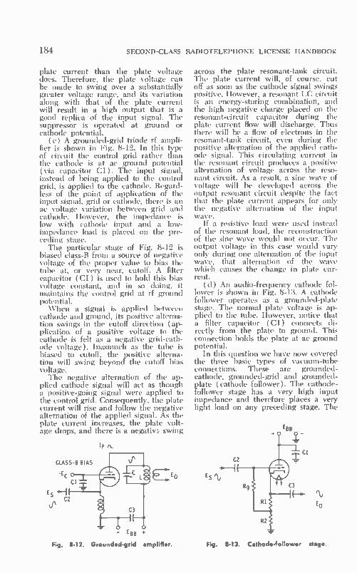
184 SECOND-CLASS RADIOTELEPHONE LICENSE HANDBOOK
plate current than the plate voltage does. Therefore, the plate voltage can be made to swing over a substantially greater voltage range, and its variation along with that of the plate current will result in a high output that is a good replica of the input signal. The suppressor is operated at ground or cathode potential.
(e) A grounded-grid triode rf ampli-fier is shown in Fig. 8-12. In this type of circuit the control grid rather than the cathode is at ac ground potential (via capacitor Cl). The input signal, instead of being applied to the control grid, is applied to the cathode. Regard-less of the point of application of the input signal, grid or cathode, there is an ac voltage variation between grid and cathode. However, the impedance is low with cathode input and a low-impedance load is placed on the pre-ceding stage. The particular stage of Fig. 8-12 is
biased class-B from a source of negative voltage of the proper value to bias the tube at, or very near, cutoff. A filter capacitor (C1) is used to hold this bias voltage constant, and in so doing, it maintains the control grid at rf ground potential. When a signal is applied between
cathode and ground, its positive alterna-tion swings in the cutoff direction ( ap-plication of a positive voltage to the cathode is felt as a negative grid-cath-ode voltage). Inasmuch as the tube is biased to cutoff, the positive alterna-tion will swing beyond the cutoff bias voltage. The negative alternation of the ap-
plied cathode signal will act as though a positive-going signal were applied to the control grid. Consequently, the plate current will rise and follow the negative alternation of the applied signal. As the plate current increases, the plate volt-age drops, and there is a negativf: swing
IP
CLASS-8 BIAS
-EC
Es IH C2
E BB
Fig. 8-12. Grounded-grid amplifier.
across the plate resonant-tank circuit. The plate current will, of course, cut off as soon as the cathode signal swings positive. However, a resonant LC circuit is an energy-storing combination, and the high negative charge placed on the resonant-circuit capacitor during the plate current flow will discharge. Thus there will be a flow of electrons in the resonant-tank circuit, even during the positive alternation of the applied cath-ode signal. This circulating current in the resonant circuit produces a positive alternation of voltage across the reso-nant circuit. As a result, a sine wave of voltage will be developed across the output resonant circuit despite the fact that the plate current appears for only the negative alternation of the input wave.
If a resistive load were used instead of the resonant load, the reconstruction of the sine wave would not occur. The output voltage in this case would vary only during one alternation of the input waVe, that alternation of the wave which causes the change in plate cur-rent.
(d) An audio-frequency cathode fol-lower is shown in Fig. 8-13. A cathode follower operates as a grounded-plate stage. The normal plate voltage is ap-plied to the tube. However, notice that a filter capacitor (Cl) connects di-rectly from the plate to ground. This connection holds the plate at ac ground potential.
In this question we have now covered the three basic types of vacuum-tube connections. These are grounded-cathode, grounded-grid and grounded-plate (cathode follower). The cathode-follower stage has a very high input impedance and therefore places a very light load on any preceding stage. The
EBB
C2
Fig. 8-13. Cathode-follower stage.

ELEMENT III TUBES AND TRANSISTORS
de component of voltage developed across the RI portion of the total cath-ode resistance serves as the bias for the stage. External battery or supply-line bias can be used if desired. The cathode follower has a low
output impedance, and unlike the grounded-cathode or grounded-grid configurations, the voltage gain of a cathode follower is always less than 1. The input signal is applied between grid and ground, and the output signal is removed from between cathode and ground. The positive alternation of the input signal causes an increase in plate current. This plate current, in flowing through the cathode resistor as cathode current, causes an increase in voltage across the cathode resistor. A negative alternation of the input signal causes a decrease in plate and cathode currents, and therefore a decrease or negative swing across the cathode resistor. It is to be noted that with the cathode-follower connection, the output and in-put voltages are in phase. Input and output voltages are also in phase for a grounded-grid amplifier. Only with the grounded-cathode configuration are in-put and output voltages exactly 180° out-of-phase.
I, I p2
Fig. 8-14. Pentode push-pull class-8 amplifier
stage.
(e) A push-pull pentode audio am-plifier for class-B operation is shown in Fig. 8-14. In a push-pull audio class-B amplifier, it is possible to obtain an out-put that is a good replica of the input wave. Even though each tube conducts only during one alternation of the in-put wave, they conduct alternately, and therefore the complete input wave is reconstructed in the output. Both tubes are biased class-B, with the use of an external bias. The circuit arrangement
185
is such that an ac ground potential ex-ists at the center of the input-trans-former secondary and the center of the output-transformer primary. Plate-sup-ply voltage is inserted at the center point of the output-transformer primary. The turns ratio of the input trans-
former is such that a proper impedance match and voltage step-clown exists be-tween the low-impedance input of the class-B grids and the higher-impedance output of the preceding stage. Input impedance is low because the class-B tubes draw grid current during the peaks of the positive alternations. The turns ratio of the output transformer is such that the very low impedance of the speaker is matched to the substan-tially higher-output impedance of the class-B tube. The positive alternation of the input
wave, as it appears across the second-ary of the input transformer, drives the grid of VI positive and the grid of V2 negative. Inasmuch as the tubes are biased class-B, V2 swings below cutoff and has no output, while the grid of VI swings in the positive direction, and there is a like change in its plate cur-rent. As a result there is a negative swing of the plate voltage of VI and an ac variation across one-half of the primary of the output transformer. Dur-ing the negative alternation of the input wave, the grid of VI swings negative into cutoff, while the grid of V2 swings in the positive direction. Therefore the plate current rises in V2 and follows the negative alternation of the input wave. This results in a decrease in the plate voltage of V2, and, conse-quently, a negative alternation of the input wave appears as a positive alter-nation across the other half of the output-transformer primary.
In summary, with a class-B push-pull connection, the complete input wave is reconstructed in the output circuit. Its phase, of course, is of opposite polarity to that of the input wave. Although amplifiers of this type, according to their biasing, are referred to as class-B amplifiers, they are not always biased exactly at cutoff. By biasing them just very slightly above cutoff, there can be a noticeable reduction in distortion.
III-48. What is meant by "space charge?" By "secondary emission?"— In the normal operation of a vacuum tube, the cathode is able to emit more electrons than the plate can accept. These excess electrons collect in a cloud

186 SECOND-CLASS RADIOTELEPHONE LICENSE HANDBOOK
between the cathode and control grid. This grouping of electrons is referred to as the space charge. Inasmuch as it is a grouping of electrons, the net charge is negative and it offers opposi-tion to the further emission of electrons from the cathode. The control grid, however, is able to
influence the electron density of this space charge; the more negative the control grid, the higher is the density. The control that the grid exerts is used to regulate the number of electrons that break away from the cloud and move on to the plate. The less negative the grid is made, the more electrons are pulled out of the space charge and pass on through the grid wires to the plate. The secondary emission of electrons
refers to those electrons dislodged from a surface by the bombardment of arriv-ing electrons. In a vacuum tube, elec-trons arrive at the plate with such im-pact that they dislodge other electrons from it. These latter electrons either fall back onto the plate or are attracted by another electrode momentarily operat-ing at a higher potential. The release of these secondary electrons from the plate is called secondary emission.
11149. What is meant by "amplification factor" (µ ) of a triode vacuum tube (amplifier)? Under what condition would the amplifier gain approach the value of 0—The p. is a measure of the 'effectiveness of a vacuum tube in pro-ducing a plate-voltage change from an applied grid-voltage change. More ex-actly, it expresses the quotient of a change in plate voltage that results from a very small change in grid volt-age, or:
tiEr = —
eiEg ( I. constant )
The gain of a vacuum-tube amplifier can be made to approach, but never reach, the value of the p. of a given tube. The higher the impedance of the load placed on the output of the tube ( providing the appropriate dc operating voltages can be maintained), the more nearly the gain of the associated ampli-fier approaches the value of p.. It can be said then that over the practical range of operation, the higher the value of the plate load resistance ( RI.), provided the proper plate voltage and grid bias are maintained and the tube is operated only over the linear portion of its charac-teristic, the higher is the possible voltage
gain and the nearer the stage gain ap-proaches the value of IL
111-50. What is meant by "plate re-sistance" of a vacuum tube? On what does its value depend?—The plate re-sistance is a measure of the influence that a plate-voltage change has on a plate-current change. It can be ex-pressed mathematically as the quotient of a small change in plate voltage over the resultant small change in plate cur-rent, or:
R = AE I'
" Ale (E. constant)
Its value depends on the influence that a changing plate voltage has on the plate current. As compared to a triode, a tetrode or pentode tube with its screen grid affords better isolation, and, there-fore, a change in plate voltage has much less influence on the plate current. This means that the plate resistance of a tetrode or pentode is much higher than that of a triode, as discussed previously in connection with Question III-46. The more effective the screen-grid volt-age is in controlling the plate current, the higher the plate resistance of a tube.
III-51. What is meant by the voltage gain of a vacuum-tube amplifier? How does it achieve this gain?—The voltage gain of an amplifier is the quotient of the ac output voltage over the ac input voltage. Expressed as an equation:
E. Cain = —
E,.
Voltage gain is the result of the ampli-fication ability of the tube. A small grid-voltage change results in a sub-stantial plate-current change. This plate-current change in a moderate to high value of load resistance results in a plate-voltage change that is of greater magnitude than the input-signal change. The activity of the tube in amplifying an applied signal was covered in detail in part (a) of Question 111-47.
III-52. Draw a rough graph of plate current versus plate-supply voltage for three different bias voltages on a typi-cal triode vacuum tube. (a) Explain, in a general way, how the value of the plate-load resistance affects the portion of the curve over which the tube is operating. How is this related to distor-tion? (b) Operation over which por-

10-
E
ELEMENT HI TUBES AND TRANSISTORS
SIGNAL Ip SHOULD
20 - NOT e SWING
POSITIVE
15
HIGH DISSIPATION 0,0
VOLTS 25
OPERATING POINTS
Ep 300
DISTORTION IN CURVED REGION
Fig. 8-15. Load lines on triode characteristics curve.
tion of the curve produces the least dis-tortion?—Such a set of curves is shown in Fig. 8-15. On these curves several load lines corresponding to different values of load resistance have been drawn. It can be noted that for a given grid-voltage (peak-to-peak swing be-tween 0 and —2 volts), a higher out-put voltage with a lower operating de plate current can be obtained with the highest value of load resistance.
However, distortion is also a factor that is influenced by the value of the load resistance. Thus an optimum value of load resistance is a function of both gain and tolerable distortion. The high-est resistance load line crosses over some of the curved portions of each of the bias curves. Therefore, the response of the amplifier is not linear in these segments, and distortion can result. With too low a value of load resistance the gain is limited, and the operating point may be of some value that will cause the safe plate dissipation of the tube to be exceeded. The load line must also be positioned
at such a location that the applied sig-nal does not swing the grid any further positive than zero, or any further nega-tive than the curved portion of the bias curve near cutoff. Any positive swing of the grid voltage results in grid-cur-rent flow and distortion of the input wave. A swing into cutoff clips off a portion of the output wave.
187
(b) An operating point and load-line value must be selected in accordance with the supply voltage and the maxi-mum amplitude of the input wave. It should be positioned so that the signal variation occurs over the linear portions of the bias curves. Operations should be concentrated mainly in the section of the characteristics where there is uni-form spacing among the individual bias curves. Distortion is caused by a posi-tive swing beyond zero and a negative swing into the curved and closely spaced regions of the bias curves near cutoff.
III-53. Draw a rough graph of plate-current versus grid-voltage (I, vs E„) for various plate voltages on a typical triode vacuum tube. (a) How would output current vary with input voltage in class-A amplifier operation? class-B operation? class-C operation? (b) Does the amplitude of the input signal de-termine the class of operation? (c) What is meant by current-cutoff bias voltage? (d) What is meant by plate current saturation? (e) What is the re-lationship between distortion in the output waveform and: ( 1) the class of operation; (2) the portion of the trans-fer characteristic over which the signal is operating; and (3) amplitude of in-put signal? (f) What occurs in the grid circuit when the grid is "driven" posi-tive? Would this have any effect on biasing? (a) In what way is the output current related to the output voltage? —A typical set of I!, vs E„ triode curves are shown in Fig. 8-16. The transfer-characteristics drawing of Fig. 8-17 can also be used in understanding the vari-ous classes of amplifier operation.
(a) In a class-A amplifier, the output plate current is a replica of the input voltage (Fig. 8-17). Plate current ap-pears during the entire cycle of the in-put-voltage wave. A class-B amplifier as
p
20 mA
15
10
CUTO BIAS VALUES
-6 I .2
Fig. 8-16. I,. — E„ characteristics of a triode.

188 SECOND-CLASS RADIOTELEPHONE LICENSE HANDBOOK
shown is biased at cutoff. Thus, with an applied input sine wave the tube conducts only during the positive alter-nation of the input wave. This is to say, plate current occurs for only 180° of the input wave.
Class-AB bias refers to some level of bias between strictly class-A and strictly class-B. In this class the plate current occurs for something more than 180° but less than 360° of the input cycle, and plate current occurs for the entire positive alternation of the input wave and for a portion of the negative alternation. In class-C amplifier opera-tion the tube is biased beyond cutoff. As a result, plate current occurs for only a portion of the positive alternation of the input wave. In a typical class-C amplifier the plate current may occur for only 90° to perhaps 150° of the in-put cycle.
(b) The class of operation of an am-plifier is mainly determined by the dc biasing of that amplifier and can be in-fluenced by the magnitude of the alter-nating grid voltage. It must be stressed, depending on the type of circuit, that the amplitude of the input signal can influence the type of bias if it in some way changes the bias or, in the case of class-A operation, is great enough to swing beyond cutoff. In the latter case, plate current will not be present during the entire input wave. In signal-biased circuits the type of bias established is very much a function of the magnitude of the input signal.
(c) Current-cutoff bias voltage is the negative grid voltage at which the plate current falls to zero. It should be noted from Fig. 8-16 that the higher the oper-ating plate voltage, the higher the nega-tive cutoff bias needed to reduce the plate current to zero.
(d) The plate is said to be saturated when it accepts all the electrons emit-
-E
Fig. 8-17. Class-A, -8, and -C bias.
ted from the cathode, and an increase in the plate voltage causes no significant increase in the plate current. With plate saturation there is no
space charge, because all of the elec-trons are attracted to the plate as fast as they are emitted from the cathode.
(e) Related distortions in the output waveform are dependent on:
( 1) In a typical single-ended audio amplifier an essentially nondistorted output is obtained only when the am-plifier is operated linear class-A. For push-pull operation an essentially non-distorted output can be obtained using class-A, class-AB, or class-B. The above statements are also correct
for radio-frequency amplifiers. In addi-tion, with an appropriate resonant load (LC circuit) radio-frequency single-ended and push-pull amplifiers can also be biased class-B or class-C, and the output wave becomes a good replica of the input wave. However this latter statement does not apply for a class-C amplifier when the radio frequency wave is amplitude modulated.
(2) Distortion also depends on the portion of the transfer characteristic over which the tube is operated. Non-distorted output is only obtained when the tube is operated over the linear portion of its characteristic or, as in the case of class-B, when a push-pull con-nection is employed. Driving the grid beyond zero or into the saturated region of the tube characteristic produces a distorted output. Likewise, a signal swing into the crowded portion of the curves near cutoff results in a distorted output.
(3) The amplitude also influences distortion. Even though a tube is biased on the linear part of its characteristic, a high-amplitude signal can swing the grid positive or into the crowded region near cutoff. Distortion will result de-spite the attempted linear biasing of the stage.
(f) When the grid is driven positive, the control grid attracts some of the electrons emitted from the cathode. Thus it removes electrons from the stream moving between the cathode and plate. The higher the positive swing of grid voltage, the more elec-trons it removes from the electron stream. The grid current reduces the input
resistance of the stage and places a greater load on the preceding source of signal. When grid current occurs, addi-tional power must be supplied from the
ELEMENT III TUBES AND TRANSISTORS
source of signal if the desired rise in grid voltage is to be attained. If that required power is not available, the in-put wave will be lonited or clipped by the flow of grid current.
If there is an RC time constant in the grid circuit, tie grid current will build up a charge on the capacitor. The average charge on the capacitor will be a dc component that, in effect, will change the normal grid bias of the stage. With a time constant present, the grid current will also affect the de operating bias of the stage in addition to its possi-ble influence on the instantaneous grid-voltage rise. ( g) In the typical audio amplifier and
in other amplifier types, there is a linear relatiolisliip between Output ( plate ) current change and output voltage (plate) change. The two components, however, are 180° out-of-phase. When the plate current increases, the output voltage decreases, and vice versa. An increase in the plate current results in a greater voltage drop across the load and a lower instantaneous plate voltage. Since the output is removed between the plate and cathode, this plate-volt-age change is the actual output voltage of the amplifier. Conversely, with a de-crease in plate current, there is a lower voltage drop across the load and a higher plate and output voltage.
III-54. Why is the efficiency of an am-plifier operated class-C higher than one operated class-A or class-B?—The efficiency of a vaumm tube, as related to its plate circuit, has to do with the efficiency of the conversion from de plate-power input to ac power output. In a class-A amplifier the plate current occurs for the entire input cycle. The de component of plate current is high and at the level of the operating point.
In a class-B stage, plate current oc-curs only during one alternation of the input wave, and therefore the average de component of plate current is less and the de power input is lower.
In a class-C amplifier the plate cur-rent occurs for an even smaller per-centage of the total input-wave cycle. The de input current is the average of these bursts of plate current. Therefore the average or dc component of current and power input are substantially less for a given swing in plate current and plate voltage, as compared to class-A or class-B operation. The plate must only dissipate power when current is drawn and as a result :he class-C stage oper-
189
ates at an even higher efficiency; that is, a greater power output for a given de power input can be obtained from class-C operation as compared to class-A and class-B.
III-55. Compare tetrode tubes to triode tubes in reference to high plate current and interelectrode capacitance.—In a tetrode tube the significant interelec-trode grid-plate capacitance (C.,.) is much less than that of a triode. A triode has a substantially higher input capaci-tance than a tetrode. The screen grid functions as an electrostatic shield be-tween the control grid and the plate. Therefore the effective or net capaci-tance between grid and plate is very much less. The plate resistance of a tetrode is
much higher than that of a triode, and, therefore it can operate into a high-impedance load in a more optimum manner. Therefore, for a comparable output, a smaller output plate-current variation and de plate current is re-quired.
This does not mean that tetrode tubes cannot be made with high de or ac cur-rent capabilities. I ligh-powered tetrode and pentode tubes are available. When they are used, a high-current and high-power output can be obtained with less input driving power than that needed for a comparable output with a triode tube. It is said that tetrodes and pen-todes have a higher power sensitivity than a triode.
III-56. What is the principal advantage of a tetrode tube over a triode tube as a radio-frequency amplifier?—The prin-cipal advantage of a tetrode tube as a radio-frequency amplifier is the fact that it requires no neutralization, be-cause of the isolation between input and output provided by the screen grid. Almost as important an advantage is the fact that it has a higher power sen-sitivity. Thus, in higher-powered rf am-plifiers it provides a greater power out-put for a given rf driving power.
III-57. A triode, "grounded-cathode" audio amplifier has a ¿I (amplification factor) of 30, a plate impedance of 5000 ohms, load impedance of 10,000 ohms, plate voltage of 300 volts, plate current of 10 milliamperes, cathode-resistor bias is used. (a) What is the stage gain of this amplifier? (b) What is the cutoff-bias voltage, E,..? (c) As-suming the bias voltage is one-half the

190 SECOND-CLASS RADIOTELEPHONE LICENSE HANDBOOK
value of E„0, what value cathode re-sistor would be used to produce the re-quired bias? (d) What size capacitor should be used to sufficiently bypass the cathode resistor if the lowest approxi-mate frequency desired is 500 hertz?— ( a ) The gain of the amplifier is deter-mined with the basic voltage gain equa-tion of a triode audio amplifier:
Gain MR,. r,, RL
30 x 10,000 Gain 500_ ±
10,000 = 20
(b) The approximate cutoff bias or projected cutoff can be calculated as follows:
Eb 300 — — — — — —10 volts — 30
( c) If it is assumed that the operat-ing bias voltage is one-half the cutoff value, the ohmic value of the cathode resistor must be as follows:
E. „
Rb 2 5 = = = 500 ohms Ib 0.01
(d) Quite often the low-cutoff fre-quency refers to that frequency at which the response is down 29.3% ( —3 dB) from the stage gain at mid-frequency. In this case the reactance of the capacitor at 500 hertz would have to be equal to the ohmic value of the resistor. It is also a common practice to assume that the response would be down no more than several percent when the reactance of the capacitor is made equal to 1/5 of the ohmic value of the resistance at a desired low fre-quency. Based on this latter condition the value of the cathode bypass capaci-tor would have to be:
Rk 500 — — = 100 ohms — 5 — 5
1 1 Ck
27rfX, — 6.28 x 500 x 100 .= 3.18 i.t.F
III-58. Are there any advantages or disadvantages of filament-type vacuum tubes when compared to indirectly heated types?—Disadvantages of the filament-type tube are that they are more subject to hum than corresponding heater-type tubes, lower emission effi-ciency, and high operating tempera-
tures. Their advantages are the ability to generate high currents and to oper-ate under adverse operating conditions including very high anode voltages. A filament type is also subject to un-
even loss of filament emission because one end of the filament is at a higher potential than the other end. This can be avoided by reversing filament volt-age polarity on a scheduled basis.
III-59. What kind of vacuum tube re-sponds to filament reactivation, and how is reactivation accomplished?— Tubes using thoriated filaments can be reactivated. Low emission results when the thorium layer has partially dissi-pated. However, there is some thorium still dissolved in the filament, and it can be brought to the surface by a tem-porary increase in the filament tempera-ture. It is accomplished by first using a high flashing temperature with a fila-ment voltage several times higher than normal for a short interval, and then holding the temperature for a lengthier period of time while operating at a temperature set by a filament voltage 50% above normal.
III-60. The following are excerpts from a tube-manual rating of a beam pen-tode. Explain the significance of each item. Control grid-to-plate capacitance, 1.1 pF; input capacitance, 2.2 pF; out-put capacitance, 8.5 pF; heater voltage, 6.3 volts; maximum de plate-supply voltage, 700 volts; maximum peak-posi-tive pulse voltage, 7000 volts; maximum negative-pulse plate voltage, 1500 volts; maximum screen-grid voltage, 175 volts; maximum peak-negative control-grid voltage, 200 volts; maximum plate dis-sipation, 200 watts; maximum screen-grid dissipation, 30 watts; maximum de cathode current, 200 mA; maximum peak-cathode current, 700 mA; maxi-mum control-grid circuit resistance, 0.47 megohm.—The control grid-to-plate capacitance is the interelectrode capaci-tance that exists between the control grid and the plate electrodes of the tube. This is the important interelec-trode capacitance ( The input capacitance has to do with
the capacitance that exists mainly be-tween the grid and the cathode (Cie) plus the influence that Cg„ and the out-put circuit might have on the total net capacitance seen across the input. The output capacitance is that capacitance that exists between the plate and the cathode (COL ).
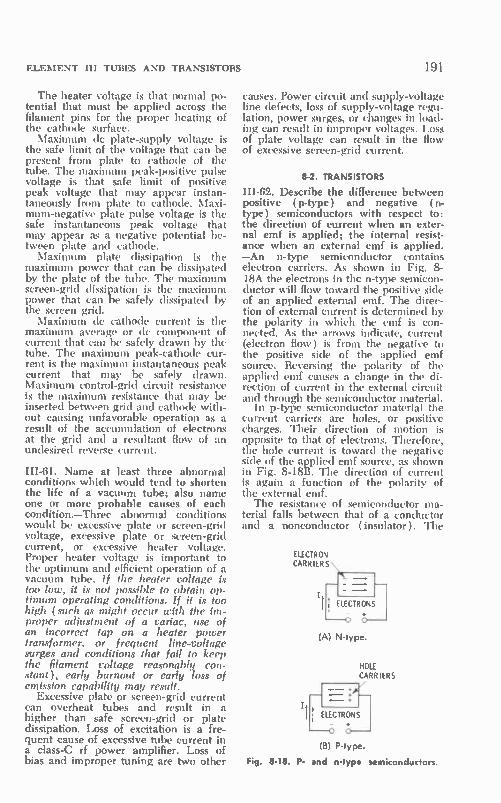
ELEMENT 111 TUBES AND TRANSISTORS
The heater voltage is that normal po-tential that must be applied across the filament pins for the proper heating of the cathode surface. Maximum de plate-supply voltage is
the safe limit of the voltage that can be present from plate to cathode of the tube. The maximum peak-positive pulse voltage is that safe limit of positive peak voltage that may appear instan-taneously from plate to cathode. Maxi-mum-negative plate pulse voltage is the safe instantaneous peak voltage that may appear as a negative potential be-tween plate and cathode. Maximum plate dissipation is the
maximum power that can be dissipated by the plate of the tube. The maximum screen-grid dissipation is the maximum power that can loe safely dissipated by the screen grid. Maximum de cathode current is the
maximum average or dc component of current that can be safely drawn by the tube. The maximum peak-cathode cur-rent is the maximum instantaneous peak current that may be safely drawn. Maximum control-grid circuit resistance is the maximum resistance that may be inserted between grid and cathode with-out causing unfavorable operation as a result of the accumulation of electrons at the grid and a resultant flow of an undesired reverse current.
III-61. Name at least three abnormal conditions which would tend to shorten the life of a vacuum tube; also name one or more probable causes of each condition.—Three abnormal conditions would be excessive plate or screen-grid voltage, excessive plate or screen-grid current, or excessive heater voltage. Proper heater voltage is important to the optimum and efficient operation of a vacuum tube. If the heater voltage is too low, it is not possible to obtain op-timum operating conditions. If it is too high (such as might occur with the im-proper adjustment of a variac, use of an incorrect tap on a heater power transformer, or frequent line-voltage surges and conditions that fail to keep the filament voltage reasonably con-stant), early burnout or early loss of emission capability may result.
Excessive plate or screen-grid current can overheat tubes and result in a higher than safe screen-grid or plate dissipation. Loss of excitation is a fre-quent cause of excessive tube current in a class-C rf power amplifier. Loss of bias and improper tuning are two other
191
causes. Power circuit and supply-voltage line defects, loss of supply-voltage regu-lation, power surges, or changes in load-ing can result in improper voltages. Loss of plate voltage can result in the flow of excessive screen-grid current.
8-2. TRANSISTORS
III-62. Describe the difference between positive ( p-type ) and negative ( n-type ) semiconductors with respect to: the direction of current when an exter-nal emf is applied; the internal resist-ance when an external emf is applied. —An n-type semiconductor contains electron carriers. As shown in Fig. 8-18A the electrons in the n-type semicon-ductor will flow toward the positive side of an applied external emf. The direc-tion of external current is determined by the polarity in which the emf is con-nected. As the arrows indicate, current (electron flow) is from the negative to the positive side of the applied emf source. Reversing the polarity of the applied emf causes a change in the di-rection of current in the external circuit and through the semiconductor material.
In p-type semiconductor material the current carriers are holes, or positive charges. Their direction of motion is opposite to that of electrons. Therefore, the hole current is toward the negative side of the applied emf source, as shown in Fig. 8-I8B. The direction of current is again a function of the polarity of the external emf. The resistance of semiconductor ma-
terial falls between that of a conductor and a nonconductor (insulator). The
ELECTRON CARRIERS
(A) N-type.
HOLE CARRIERS
(B) P-type.
Fig. 8-18. P- and n-type semiconductors.

192 SECOND-CLASS RADIOTELEPHONE LICENSE HANDBOOK
actual resistance depends very much on the number of free carriers (electrons or holes) in the semiconductor material. The number of these free carriers de-pends on the percentage of a specified impurities that have been added to the pure crystalline semiconductor material. This is referred to as doping the pure semiconductor material—the greater the doping, the more current carriers and the lower the resistance of the semi-conductor material with an applied emf. When two such portions of semicon-
ductor material are combined to form a junction, they provide rectifier action and a unidirectional current. When the junction is said to be forward biased (Fig. 8-19A), the positive terminal of the external source of emf is connected to the p-side; the negative terminal to the n-side. The electron carriers of the n-side flow through the junction to the positive terminal, while the hole carriers of the p-side flow in the opposite direc-tion through the junction to the nega-tive terminal. The junction now has a low resistance and a significant external current is present in the circuit.
If the junction is back or reverse biased, as in Fig. 8-19B, the electron
,--
cc C.) Ot 0
ex
P + N
E
▪ -
(A) Forward bias.
.-z
=ce
N
NO CURRENT
o "(t)
(B) Reverse bias
Fig 8-19 The pn junction and its rectifier characteristics.
carriers of the n-side move to the posi-tive terminal and the hole carriers of the p-side to the negative terminal. There is no motion of carriers across the junc-tion, and the resistance of the junction is high. Very little or no external current flows.
III-63. What is the difference between forward and reverse biasing of tran-sistors?—When a transistor junction is forward biased, it is so biased that the junction resistance is low, and there is a free motion of carriers through that junction. The reverse and forward bias-ing of a junction is shown in Fig. 8-19. With forward bias, the junction resist-ance is low. With reverse or back bias-ing the junction resistance is high.
In a normal transistor circuit (Fig. 8-20) the emitter-base junction is for-ward biased, and the collector-base junction is reverse biased. Note that the manner of connection of the bias volt-ages depends on whether the transistor is a pnp or npn type.
Notice that the emitter-base junction or just emitter junction is forward bi-ased. Since the emitter junction is for-ward-biased, there is, in the case of an npn transistor, a motion of electrons across the junction into the base. Some of these electrons are neutralized by holes in the p-type base. However, the emitter is more highly doped than the
EMITTER COLLECTOR JUNCTION JUNCTION
Pi N + P
FORWARD BIAS
REVERSE BIAS
(A) Pnp type.
EMITTER COLLECTOR JUNCTION JUNCTION
N+ P +N
FORWARD REVERSE BIAS BIAS
(B) Npn type.
Fig. 8-20. Normal biasing of transistors.

ELEMENT III TUBES AND TRANSISTORS
base (fewer holes than injected elec-trons), and therefore a great many of the electrons are not neutralized and move through the base to the collector junction. Here they are attracted to the positive voltage of the collector and are pulled across the collector junction (even though it is reverse biased in terms of the collector-base bias) and out into the external circuit. The tran-sistor amplifies because this current is greater than the much smaller base cur-rent that occurs as a result of charge neutralization in the base. Also, gain is possible because the transistor output resistance is high (collector junction is reverse biased) and its input resistance
INPUT
INPUT—e—I
VCC
(A) Npr type.
III* yes VCC
(8) Pnp type.
H.-OUTPUT
H- OUTPUT
Fig 8-21. Properly biased common-emitter stage.
is low (emitter junction is forward bi-ased), and even an identical current would produce a greater output voltage (IR) and power (PR).
III-64. Show connections of external batteries, resistance load, and signal source as would appear in a properly (fixed) biased common-emitter transis-tor amplifier.—Basic circuits for pnp and npn transistors are shown in Fig. 8-21.
193
Note that for normal operation the po-larity of the bias sources is opposite for pnp and npn transistors. The polarity, of course, must be selected to forward bias the emitter junction and reverse bias the collector junction.
In the operation of the common-emit-ter stage the emitter junction is for-ward biased from the battery (Vent). Resistor Rb has a value that results in a proper bias current through the emitter junction. The direction of current is such that the emitter junction is biased in the forward direction. Some bias ap-pears across RE but it is not of a po-larity to forward bias the emitter junc-tion. However, it is useful in stabilizing the transistor operating point with rela-tion to temperature change. Resistor RI, is the output load resistor. The ampli-fied current (L.) through Ri. develops the output voltage. When an ac signal is applied to the
base circuit, it causes a variation in the base-emitter voltage and base current. There is a like variation in the number of carriers injected into the base region and a follow-up change in the collector current. The variation of the collector current is greater than the signal varia-tion of the base current, and amplifica-tion results. The change in collector cur-rent through the load resistor develops the amplified signal across the output of the common-emitter amplifier. A more detailed explanation follows:
In the common-emitter amplifier of Fig. 8-21A, the base-to-emitter junc-tion is forward biased and the base-to-collector junction is reverse biased. The signal is applied between the base and emitter. Since the base is forward bi-ased. electrons move from the emitter, cross the emitter junction, and into the base. It is said that carriers are injected into the base through the emitter junc-tion. The magnitude of the carrier in-jection is a function of the signal varia-tion applied to the base. This is similar to the action of a conventional vacuum tube, where the control grid controls the variation of electron flow through the grid wires as they travel from cath-ode to plate. Many more electron carriers are in-
jected into the base than are required to sustain the base-emitter current. These carriers diffuse across the base to the collector junction. At the collector junction they are attracted by the posi-tive potential of the collector and they are propelled through the collector junction into the collector element.

194 SECOND-CLASS RADIOTELEPHONE LICENSE HANDBOOK
Even though the collector-base junc-tion is reverse biased, there has been a free motion of electrons across the base, through the collector junction and the collector element, into the collector out-put circuit. As a result, there is a col-lector-emitter current through the out-put load resistor ( RI.). This current is a function of the signal voltage applied to the base. Inasmuch as the collector-emitter circuit has a high resistance, an amplified voltage is developed across the collector load resistor.
Input voltage and output voltage are out-of-phase for the common-emitter circuit. When the input signal swings positive the base-emitter junction swings in the direction of more forward bias. Hence, the base current increases and so does the collector current. The higher collector current produces a drop in the collector voltage and a negative swing of the output voltage. Oppositely, when the input signal swings negative, the forward bias is reduced on the emit-ter junction. As a result the hase cur-rent and the collector current decline correspondingly. There is a resultant rise in the collector voltage and a posi-tive swing of the output voltage.
III-65. The following are excerpts from a transistor handbook describing the characteristics of a pnp alloy-type tran-sistor as used in a common-emitter con-figuration. Explain the significance of each item.
Maximum and Minimum Ratings
Col lector-to-Base Voltage (emitter-open) —40 Max. Volts
Collector-to-Emitter Voltage (base-to-emitter volts = —0.5) —40 Max. Volts
Emitter-to-Base Voltage —5 Max. Volts Collector Current 10 Max. mA
Transistor Dissipation At AmWent Temperature of 25 °
for Operation in Free Air 120 mW At Case Temperature of 25°
for Operation with Heat Sink 140 mW AmWent-Temperature Range
(operating and storage) —65 to +100°C
—The maximum value given in each of the various items must not be exceeded under any circumstances. The ambient-temperature range lists both a minimum and maximum limit. The collector-to-base maximum voltage range is the maximum reverse-bias voltage that can be applied safely. If it is exceeded, there will be a sharp damaging increase
in the current between the collector and base as a result of the break-up of the crystal lattice structure; this is called avalanche breakdown. The collector-to-emitter voltage is the
maximum voltage that can be safely ap-plied between these two elements be-fore the transistor will become inoper-ative or subject to damage. There is also a safe limit to the emitter-to-base volt-age. The particular transistor should not
be operated in any manner that causes the maximum collector current to be exceeded. Excessive current can over-heat and damage the collector junction. A transistor, according to its con-
struction is capable of dissipating safely a specific amount of heat before its junction will be damaged. Of course, if a heat sink is employed to conduct some of the heat away from the junction and case, a greater amount of heat can be dissipated safely. Maximum safe dissi-pation is given in milliwatts or watts.
Minimum- and maximum-storage tem-peratures are usually stated. When the transistor is operated at high temper-ature, the safe transistor dissipation wattage must be derated. Note that in the table the transistor dissipation is based on a case temperature of 25° C. If the operating temperature is higher than this value, the transistor dissipation wattages must be made correspondingly less according to specified derating in-formation.
III-66. Draw a circuit diagram of a method of obtaining self-bias, with one battery, without current feedback, in a common-emitter amplifier. Explain the voltage drop in the resistors.—The cir-cuit of Fig. 8-22A derives its bias from the same supply-voltage source as the collector-emitter circuit. The value of Rh is chosen with relation to the supply voltage (Vey) so that the proper series current goes through RA and the base-emitter circuit to correctly bias the emitter junction. The voltage drop across Rh is the difference between sup-ply voltage Ver and the bias required between base and emitter; or, the bias is the difference between Vev and the voltage drop across 115 or:
Junction Bias = Ver — VHS
The self-bias circuit shown in Fig. 8-22B uses local feedback to stabilize the operating point. In this bias arrange-ment the base bias is derived from the collector voltage rather than the col-

ELEMENT III TUBES AND TRANSISTORS
(A) Single-battery bias, no feedback.
-VCC
(B) True self-bias wi th feedback.
-v CC
(C) Self-bias with no ac feedback.
Fig. 8-22. Single-battery bias and self-bias arrangements.
lector-supply voltage. The collector volt-age, of course, is the difference between collector-supply voltage VrE and the de voltage drop across collector load re-sistor RL. The value of base-bias re-sistor Rb must be such that the proper base current will flow through the emit-ter junction of the transistor. The foregoing being so, the required
value of base-bias resistor Rb is lower as compared to that for the fixed-bias arrangement of Fig. 8-22A. If there is any output drift with temperature there will be a corresponding change in the collector voltage. The attempted change in collector voltage will cause a cor-rective change in the base-bias current.
195
The direction of the base-bias current change will be such that it will oppose the direction of drift of the collector current. The circuit arrangement of Fig. 8-
22C is similar to Fig. 8-22B, except that there are split bias resistors. The filter combination Rbi and Cl prevent ac feedback.
III-67. Draw a circuit diagram of a common-emitter amplifier with emitter bias. Explain its operation.—The com-mon-emitter circuit of Fig. 8-21 uses some emitter bias as developed by the flow of emitter current. As covered in Question III-64, the connection does not provide forward bias, and for this rea-son, it is also necessary to bias the base circuit. Its function is one of stabiliza-tion. However, external emitter bias can be used.
vcc
' VEE
Fig. 8-23. Emitter-bias arrangement.
In a true emitter-bias arrangement (Fig. 8-23), the emitter resistor con-nects to a separate supply voltage. The actual voltage that determines the base bias current is established by the differ-ence of potential between this supply voltage and the voltage drop across emitter resistor RE. This voltage sets the emitter-base bias voltage. The circuit arrangement also stabi-
lizes the operating point because any drift in the collector current will be felt as a change in the emitter current and in the voltage drop across emitter re-sistor RE. The resultant bias change pro-duces a compensating change in the base-bias current in a direction that will oppose any tendency for the col-lector current to drift. The operation of the common-emitter
amplifier, except for the biasing arrange-ment, is similar to that discussed in conjunction with Question III-64.
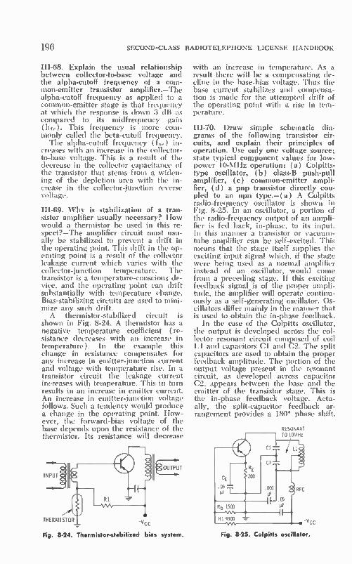
196 SECOND-CLASS RADIOTELEPHONE LICENSE HANDBOOK
III-68. Explain the usual relationship between collector-to-base voltage and the alpha-cutoff frequency of a com-mon-emitter transistor amplifier.—The alpha-cutoff frequency as applied to a common-emitter stage is that frequency at which the response is clown 3 dB as compared to its midfrequency gain (he.). This frequency is more com-monly called the beta-cutoff frequency. The alpha-cutoff frequency (f..) in-
creases with an increase in the collector-to-base voltage. This is a result of the decrease in the collector capacitance of the transistor that stems from a widen-ing of the depletion area with the in-crease in the collector-junction reverse voltage.
III-69. Why is stabilization of a tran-sistor amplifier usually necessary? How would a thermistor be used in this re-spect?—The amplifier circuit must usu-ally be stabilized to prevent a drift in the operating point. This drift in the op-erating point is a result of the collector leakage current which varies with the collector-junction temperature. The transistor is a temperature-conscious de-vice, and the operating point can drift substantially with temperature change. Bias-stabilizing circuits are used to mini-mize any such drift. A thennistor-stabilized circuit is
shown in Fig. 8-24. A thermistor has a negative temperature coefficient (re-sistance decreases with an increase in temperature). In the example this change in resistance compensates for any increase in emitter-junction current and voltage with temperature rise. In a transistor circuit the leakage current increases with temperature. This in turn results in an increase in emitter current. An increase in emitter-junction voltage follows. Such a tendency would produce a change in the operating point. How-ever, the forward-bias voltage of the base depends upon the resistance of the thermistor. Its resistance will decrease
INP.UT
THERMISTOR
Fig. 8-24. Thermistor-stabilized bias system.
with an increase in temperature. As a result there will be a compensating de-cline in the base-bias voltage. Thus the base current stabilizes and compensa-tion is made for the attempted drift of the operating point with a rise in tem-perature.
III-70. Draw simple schematic dia-grams of the following transistor cir-cuits, and explain their principles of operation. Use only one voltage source; state typical component values for low-power 10-MHz operation: ( a ) Colpitts-type oscillator, (b) class-B push-pull amplifier, (c) common-emitter ampli-fier, (d) a pnp transistor directly cou-pled to an npn type.—(a) A Colpitts radio-frequency oscillator is shown in Fig. 8-25. In an oscillator, a portion of the radio-frequency output of an ampli-fier is fed back, in-phase, to its input. In this manner a transistor or vacuum-tube amplifier can be self-excited. This means that the stage itself supplies the exciting input signal which, if the stage were being used as a normal amplifier instead of an oscillator, would come from a preceding stage. If this exciting feedback signal is of the proper ampli-tude, the amplifier will operate continu-ously as a self-generating oscillator. Os-cillators differ mainly in the manner that is used to obtain the in-phase feedback.
In the case of the Colpitts oscillator, the output is developed across the col-lector resonant circuit composed of coil Li and capacitors Cl and C2. The split capacitors are used to obtain the proper feedback amplitude. The portion of the output voltage present in the resonant circuit, as developed across capacitor C2, appears between the base and the emitter of the transistor stage. This is the in-phase feedback voltage. Actu-ally, the split-capacitor feedback ar-rangement provides a 180° phase shift.
RESONANT TO 10MHz
"VCC
Fig. 8-25. Colpitts oscillator.

ELEMENT III TUBES AND TRANSISTORS
This shift in conjunction with the 180° polarity shift of the common-emitter transistor connection provides a total shift of 3600 and, therefore, the base-emitter circuit is excited in-phase. Were the base connected to the junction of the two capacitors and the emitter to the bottom of the resonant circuit, os-cillations would not occur because the voltage fed back from the collector cir-cuit would appear out-of-phase instead of in-phase with the base-emitter varia-tion. The oscillator is stabilized with emit-
ter resistor RE and its rf filter capacitor CF:. A small amount of emitter-junction forward bias is needed to initiate the cycle that builds up to a continuous os-cillation. If this bias were not provided, the oscillator would not start. The base-bias resistors are resistors RI and Rb. The Colpitts is a widely used transis-
tor oscillator operating from a very low frequency to an exceptionally high radio frequency. If high-••alue capacitors were used along with an iron-core choke, the basic oscillator, as shown in Fig. 8-25, could be made to operate at an audio frequency.
(b) A class-B push-pull rf amplifier is shown in Fig. 8-26. Input and output resonant circuits are employed. On the input side the resonant circuit is in the primary and is excited with input from the preceding stage. The secondary is one of low impedance and provides a match to the low-impedance input of the transistor.
Inasmuch as the transistors are biased at class-B, they conduct during opposite alternations of the input wave. On al-ternate alternations, each draws a burst of collector current into the output reso-nant circuit. The energy-storing ability of the resonant circuit permits the de-velopment of a radio-frequency wave of good sine-wave form across the output
10-MHz LC CIRCUIT
INPUT
LOW OUTPUT
197
resonant circuit. This rf energy can be transferred to an antenna or to a suc-ceeding stage by way of the low-imped-ance secondary winding. A small emit-ter resistor can be used for stabilization. Optimum class-B biasing requires the
use of base bias (resistors R1 and Rs). This bias is usually just enough to over-come the emitter junction barrier poten-tial. Sometimes no external biasing is used and the transistors are biased near class-B (transistors are essentially non-conducting with no applied forward bias). The class-B stage is to operate as an
amplifier and not as an oscillator. Be-cause of the high input conductance, neutralization is often not required. For some low-power transistors (lower in-put conductance) steps must sometimes be taken to prevent feedback between the output and input resonant circuits. To prevent oscillations and reduce this tendency, crisscross neutralizing capaci-tors are employed. Note that they con-nect from the collector of one transistor to the base of the second transistor. In so doing, they provide a certain amount of negative feedback which opposes any tendency to positive feedback. With ap-propriate values the negative feedback cancels the positive feedback exactly, and the stage will operate as a stable amplifier.
(c) A common-emitter rf amplifier is shown in Fig. 8-27. This is typical of the circuit arrangements used in re-ceiver rf and i-f amplifiers. Most are bi-ased for class-A operation, using a base divider combination composed of re-sistors RI and Rh and bias filter capaci-tor Cs. An emitter resistor is used for operating-point stabilization. This re-sistor can be unbypassed if some ac negative feedback is required for sta-bilizing a high-gain radio-frequency amplifier.
TUNE —E TO 10MHz C N
27K
TUNE TO 10MHz
-Vcc
OUTPUT
Fig. 8-26. Class-8 rf amplifier. Fig. 8-27. Common-emitter rf amplifier.

198 SECOND-CLASS RADIOTELEPHONE LICENSE HANDBOOK
Again the primary side of the input transformer is resonant, while the sec-ondary provides a low-impedance match to the transistor. In the more sensitive and higher frequency-amplifier circuits, neutralization is used to improve sta-bility and avoid self-oscillations. In the arrangement of Fig. 8-27 it would be possible to connect a neutralizing ca-pacitor (CN) from the bottom of the collector resonant circuit to the base of the transistor.
(d) Pnp and npn transistors, because of the opposite biasing polarity can be conveniently direct-coupled. Two such amplifiers are shown in Fig. 8-28; a pnp transistor is direct-coupled to a succeed-ing npn transistor stage. The amplifiers shown are tuned 10-MHz stages. With proper choice of components and tran-sistors a video amplifier can also be macle to operate up to a frequency of 10 MHz and higher. Note that there is no coupling capaci-
tor, and a direct connection is made from collector of the first transistor to the base of the second stage. The bias-ing of the first stage is handled by re-sistors RI, Rb1, and emitter-stabilization resistor RE:i. Insofar as de is concerned, there is a direct path from the collector of the first stage to the base of the sec-ond stage. Therefore, the bias voltage (\THE) on the second stage is set by the current in the series circuit composed of the collector circuit of the input stage, Rb2, emitter junction, and REz. Its polarity is such that the base is made positive with respect to the emitter ( the potential of the base of the second tran-sistor is less negative than the potential at its emitter). The collector of the sec-ond transistor is, of course, at a positive potential as is required for proper bias-ing of the npn type. Thç arrows on the illustration repre-
sent electron current. For the pnp tran-sistor the current is out of the emitter and into the collector and base. Current direction is opposite for the pnp type. Observe that the first transistor has two output current paths from ground. One path is through the first transistor via the emitter junction, collector junction, and output load. The second path finds its way back to the negative supply through the emitter junction of the sec-ond transistor and emitter resistor RF:2. The current is in a direction that will forward bias the second transistor.
III-71. Discuss etched-wiring printed circuits with respect to the following:
(a) Determination of wiring breaks (b) Excessive heating (c) Removal and installation of components.—In a printed-circuit wiring chassis, soldered connecting wires have been replaced by conductive surfaces which have been printed or etched on an insulated panel. A thin copper-plated plastic laminate is used as a base. A light-sensitive chemi-cal is first coated on the copper when employing the desired process. A mask of the desired circuit-wiring ar-rangement is then positioned over the treated laminate and exposed to light. In the developing process the exposed photosensitive chemical is removed. However the coating remains on the un-exposed lines and areas. An etching bath is next used to remove the copper from the exposed portion. Finally, the photo chemical is washed away and the etched copper design remains on the laminate. The repair of printed-circuit boards
requires a low-wattage pencil-tip solder-ing iron which should be handled care-fully so as to avoid excessive heating of the board. A small wire brush can be used to clean away solder. Carbon tetra-chloride is useful for cleaning repair areas. Rosin-core solder with a low melting point is preferred in making any solder connections.
Overheating or other physical damage may cause the copper wire strips to break away from the laminate or breaks may occur in the actual interconnection strips. Some of these breaks are of the hair-line type and are difficult to locate. A magnifying lens is helpful in locating very thin breaks. An ohmmeter can also be used to advantage in finding such breaks. If a break is found between two principal connection points, one of the
Fig. 8-28. Direct-coupled amplifier.

ELEMENT III TUBES AND TRANSISTORS
ohmmeter prods can then be moved in short steps toward the other until the area of the break is localized more defi-nitely.
Excessive heating is to be avoided. Soldering irons with ratings in excess of 25 to 35 watts are not recommended. When a copper wiring strip has broken away from the laminate or has a crack, it may be repaired by cutting away the damaged section. A small piece of wire can then be soldered across the break. In all such repairs, to avoid further dam-age to the connecting copper strips do not overheat connections. Excessive solder and overheating can also damage or short out adjacent copper connections if the solder drips or spreads. The wire brush can come in handy in removing solder drippings, although a small knife blade and/or heat may be necessary to free some of the drippings.
Gentle handling is essential in the re-pair and removal of component parts and wiring from a printed-wiring board. Prying or excessive force are to be avoided to prevent damage to connec-tions and the thin-skinned laminate. Defective parts can be removed or re-placed in one of two ways. The compo-nent pigtails can be clipped as close as possible to the defective part. The pig-tails that remain connected to the board and those of the replacement part can then be soldered together.
If the removal of the component is necessary, its leads should be clipped as near as possible to the connection points. The pigtail sections remaining can then be removed with the careful application of heat. The connecting areas should then be cleaned carefully, and the pig-tails from the replacement part inserted, clipped, bent into position, and soldered. Finally, the area should be inspected very carefully and cleaned of excess solder. A protective coat of lacquer can then be applied to provide long-term protection.
III-72. What is a junction tetrode tran-sistor? How does it differ from other transistors in base resistance and oper-ating frequency?—The tetrode transis-
199
tor is similar to the three-element (tri-ode) type with the exception that a second base lead is brought out, as shown in Fig. 8-29. In the case of an npn transistor, a high-negative potential is connected between this new base lead and the regular base lead of the tran-sistor. This sets up a potential gradient across the length of the base. The volt-age decreases from a high-negative value at the one end to the positive forward-bias value at the opposite end of the base. In so doing, the flow of
N P N
E
-_-,
B
CUTOFF
C
REGION ,.;.••::"
- + I - + • ••
VEE VCC -
• • TETRODE VOLTAGE
Fig 8-29 Biasing and motion of carriers for a tetrode transistor.
carriers is modified in comparison to a conventional transistor. The effect at the top of the base (Fig. 8-29) is com-parable to the application of a reverse or cutoff bias in terms of the current from emitter to collector. The net re-sult is to block the transfer of carriers except in the narrow region at the oppo-site end of the base region where a forward bias is in effect.
This channeling of the flow of carriers reduces both the base resistance (trans-verse base resistance) and the collector capacitance because of the smaller ef-fective-collector junction area. In the operation of a transistor stage, the base resistance and collector capacitance have a restraining influence on the high-frequency performance. By reducing both of these constants, the tetrode tran-sistor is able to operate efficiently at higher frequencies as compared to a comparable triode type.
8-3. CHAPTER 8 SELF-TEST
(Answers on page 433) 1. As compared to a pentode, a triode
A. has a higher power sensitivity. C. is a more constant-current device. B. has a higher input capacitance. D. has a suppressor grid.

200 SECOND-CLASS RADIOTELEPHONE LICENSE HANDBOOK
2. An increase in transistor junction temperature causes A. a decline in emitter current. C. a rise in collector current. B. a decline in base current. D. a rise in collector voltage.
3. A screen grid A. prevents secondary emission. B. increases the influence of the
plate voltage on plate current.
C. attracts secondary electrons at low plate voltage.
D. is a solid electrode like the plate but is nearer the grid.
4. A short from grid to cathode increases A. plate current. B. grid bias.
5. The suppressor grid A. is .à)laced next to the control C. operates at plate potential.
D. is positioned after the plate. B. trocics undesired electrons.
6. A shorted screen-grid capacitor will A. increase plate current. B. decrease plate voltage.
C. plate voltage. D. screen-grid voltage.
C. overheat plate load resistor. D. overheat screen-grid resistor.
7. A pentode tube as compared to a triode A. is a more constant-voltage de- C. permits a lower minimum plate
vice, voltage swing. B. usually has a lower power D. has a high input capacitance
sensitivity.
8. An amplifier has voltage? A. 1.4V. B. 0.71V.
•
a it of 28. If output voltage is 20 volts what is
9. A class-B amplifier is A. more efficient than class-C. B. less efficient than class-AB.
10. In a thyratron circuit A. the grid loses control after igni-
tion. B. anode voltage is a replica of in-
put voltage.
C. 0.56V. D. Insufficient information.
C. never biased near cutoff. D. more efficient than class-A.
input
C. the grid is biased positive to cut off anode current.
D. no relay can be used in anode circuit.
11. Find triode stage gain if it is 30, r,, is 50,000 ohms and R. is 20,000 ohms. A. 105. B. 8.5.
C. 30. D. 75.
12. The emitter of a transistor is often compared with vacuum tube? A. Plate. B. Grid.
13. In normal operation of a transistor in A. emitter junction is forward bi-
ased; collector junction reverse biased.
B. both junctions must be forward biased.
14. A grounded-cathode amplifier A. has a high input resistance. B. has no voltage gain.
C. Suppressor. D. Cathode.
what electrode of a
a common-emitter circuit C. collector junction is forward biased;
emitter junction reverse biased. D. both junctions must be reverse
biased.
C. has a low output impedance. D. none of these mentioned.

A. 98. B. 138.
25. A grounded-grid stage has A. a low input impedance. B. no voltage gain.
ELEMENT III TUBES AND TRANSISTORS 201
15. Calculate value of cathode filter (bypass) capacitor needed for good low-frequency response down to 100 hertz. Value of cathode resistor is 1000 ohms. A. 4e. C. 2p.F. B. 81...F. D. 0.1e.
16. A positive signal applied to base of a pnp transistor connected in a com-mon-base circuit causes A. an increase in collector current. C. a rise in emitter current. B. a drop in collector voltage. D. a decrease in base current.
17. A positive signal applied to the base of a pnp transistor connected in a common-emitter circuit causes A. an increase in collector current. C. a rise in emitter current. B. a drop in collector voltage. D. a decrease in base current.
18. A positive signal applied to the base of an npn transistor connected in a common-emitter circuit causes A. an increase in base current. C. a rise in collector voltage. B. a decrease in emitter current. D. a decrease in base current.
19. The collector of a transistor is often compared to what electrode of a vacuum tube? A. Filament. C. Control grid. B. Plate. D. Cathode.
20. A triode is to be operated with cathode bias. Calculate the ohmic value of the cathode resistor if bias is —2 volts, plate voltage is 180 volts, and plate current is 4 milliamperes. A. 45,000. C. 353. B. 500. D. 2000.
21. In class-C operation plate current is present during A. the full input cycle. C. a portion of the negative alternation. B. the entire positive alternation of D. a portion of the positive alternation.
the input wave.
22. For maximum power transfer out of a triode, the ohmic value of plate load should be related to plate resistance as follows: A. equal to R. B. 2Rp.
23. The grid-plate capacitance, C.„ of A. has no influence on input capaci-
tance. B. is less for a pentode than a
triode.
C. less than R. D. 1.51tp.
a vacuum tube C. presents no neutralization problems. D. increases the plate resistance.
24. If the operating-point plate current of a vacuum tube stage is 6 mA, what is the dc plate voltage when the grid bias is —4 volts, screen current is 1.5 mA, supply voltage is 300 volts, and plate resistor is 27,000 ohms?
C. 296. D. 304.
C. a low output impedance. D. out-of-phase input and output sig-
nals.

CHAPTER 9
Element Ill Power Sources
9-1. RECTIFIERS AND FILTERS
HI-73. Discuss the relative merits and limitations as used in power supplies of the following types of rectifiers: (a) mercury-vapor diode, (b) high-vacuum diode, (c) copper oxide, (d) selenium, (e) silicon.—( a) A mercury-vapor rec-tifier tube permits a high current flow, because of the low resistance path pre-sented by the ionized gas molecules. Such a tube has a low and fixed internal voltage drop and excellent regulation. The current capability is high, and the tube is efficient in terms of required filament power and anode dissipation. Such a tube is critical of operating tem-perature, and some delay is involved in bringing the cathode up to optimum temperature. It has a lower peak-inverse voltage (piv) than a high-vacuum type and includes output transients ( gas ioni-zation process) that can be a source of rf interference.
(b) The high-vacuum rectifier can withstand a higher peak-inverse voltage and is less critical of operating tempera-ture as compared to the mercury vapor. It is not as economical and presents some voltage-regulation problems for power demands that change substan-tially. Rf interference and transients are not a problem.
(e) The copper-oxide diode is a metallic rectifier. It is a small, low-cur-rent, low-voltage rectifier principally used in ac meters. It has a long life and constant characteristics and can be made economically.
(d) The selenium diode is also a me-tallic rectifier. Low- and high-current versions can be fabricated and made to have a high peak-inverse voltage (ap-proximately three times that of a copper
oxide type). They are somewhat more costly than the copper oxide type but are less subject to temperature changes and are more rugged.
(e) The silicon solid-stage rectifier is taking over many of the duties of both high-vacuum and mercury-vapor recti-fiers. Its regulation is good, and it can be fabricated to handle very high cur-rents. Furthermore, no filament power is required. Peak-inverse voltages are lower than high-vacuum types, but this disadvantage is readily overcome by connecting a number of silicon rectifiers in series. They are subject to damage by current surges, and a protective series resistance is usually required.
III-74. Explain the action of a voltage regulator (vr) tube.—The voltage reg-ulator is a cold-cathode type tube and maintains a constant output voltage over its operating range. It is used widely whenever a low-current and constant-voltage power source is re-quired. As shown in Fig. 9-1, the supply volt-
age for the load is taken off directly across the tube. A series resistor con-fines the current within the limits of operation of the vr tube. An adequate voltage must be made available so that the gas in the vr tube ionizes. As the load current changes, more or less cur-rent is shuttled through the vr tube and a constant voltage drop is main-tained. When the load current increases, there is less current through the vr tube. Conversely, when the load current decreases, more current is shuttled through the vr tube. The resistance of the conducting path (offered by the ionized gas molecules) varies with out-put-current demand in such a manner
202

ELEMENT III POWER SOURCES
SERIES RESISTOR
UNREGULATED DC INPUT VOLTAGE
Fig. 9-1. Voltage-regulator circuit.
LOAD
that a constant voltage drop is main-tained across the tube.
III-75. Draw a diagram of each of the following power-supply circuits. Explain the operation of each, including the relative input- and output-voltage am-plitudes, waveshapes and current wave-forms: (a) vacuum-tube diode, half. wave rectifier with a capacitive-input "pi-section" filter; (b) vacuum-tube di-ode, full-wave rectifier with choke-input LC filter; (c) silicon diode, doubler-circuit rectifier with a resistive load; ( d ) nonsynchronous-vibrator power supply with a silicon diode, bridge-circuit rectifier, and a capacitive-input "pi-section" filter; ( e ) synchronous-vibrator power supply with a capaci-tive-input "pi-section" filter.—( a ) A half-wave rectifier with a capacitive-input filter is shown in Fig. 9-2. Appro-priate waveforms are shown. To under-stand its operation let's first assume that the filter is not connected (broken at point X). During the positive alterna-tion of the input sine wave as it appears across the secondary of the transformer, a positive voltage is applied to the plate of the diode rectifier. As a result, elec-trons are attracted from the cathode emitting surface. The more positive the anode is with respect to the cathode, the more electrons there are that flow and the higher the current. This current
203
through resistance RL develops a load voltage that corresponds to the positive alternation of the input sine wave. Dur-ing the negative alternation of the input wave, the plate is made negative with respect to the cathode. Consequently, no electrons are attracted over to the plate, and the circuit resistance is essen-tially infinite. No current occurs, and there is zero voltage drop across re-sistor RL. Current has been in one di-rection, and it only occurs when the plate is made positive with respect to the cathode. A pulsating voltage, cor-responding to the positive alternations of the input wave, is developed across the load.
Next consider how the filter influences the operation of the power circuit. Dur-ing the conducting alternation, the in-put capacitor charges toward the peak amplitude of the positive alternation. When little power is being demanded by the load, the capacitor charges to the very peak of the positive alternation. If a considerable amount of current is drawn from the supply by the load, the capacitor does not charge to the peak magnitude. The load continues to demand cur-
rent even after the peak of the positive alternation has been passed. As a result, charge is withdrawn from the capacitor to supply current to the load, and the magnitude of that capacitor charge (voltage) decreases. However, during each positive alternation the charge is replenished by the conducting interval of the rectifier tube. Note the capacitor and output voltages.
As shown in the waveforms, the tube conducts for even less than the time in-terval of the positive alternation of the input wave. It conducts just long
PEAK
CAPACITOR CHARGE
SECONDARY AC
o
o
CHARGE ON CI
JLL DIODE CURRENT
DC OUTPUT VOLTAGE
Fig. 9-2. Half-wave rectifier with capacitive-input filter.

204 SECOND-CLASS RADIOTELEPHONE LICENSE HANDBOOK
enough to replenish the charge on the input capacitor—the greater the power demand of the load for a given set of filter components, the longer the period of the rectifier current. It follows from this that there is a higher average cur-rent and a higher de output current as demanded.
Current through the load is in only one direction. The purpose of the recti-fier is to cause this unidirectional cur-rent. The purpose of the filter is to smooth out the pulsations so that the de output voltage remains essentially con-stant, and a constant de current goes through the load. Heater power is de-rived from the transformer filament winding. The larger the input capacitor and
the greater the energy storing capabil-ity of the pi-section filter, the more ef-fectively the pulsations are filtered out into a smooth de voltage and current. It is permissible to state that the capaci-tor opposes a change in voltage and therefore holds the voltage constant to the best of its ability. The inductor op-poses a change in current and helps smooth out the current in the rectifier-filter circuit. The time constant of the filter and load is long in comparison to the period of the ac sine wave.
(b) A full-wave rectifier with a choke-input filter is shown in Fig. 9-3. Consider its operation first without the filter ( Fig. 9-3B ). The top rectifier plate is connected to the top of the secondary winding of the transformer. Its opera-
Fig
tion is identical to that of the single half-wave rectifier of Fig. 9-2. It pro-duces positive pulsations across the load during the positive alternations of the secondary input wave. The magnitude of the pulsations depends on the ampli-tude of the sine wave as it appears be-tween the top of the secondary and the center tap. The bottom half of the rectifier tube
has its plate connected to the bottom side of the transformer secondary. As a result, it is the negative alternation of the secondary sine wave that causes the plate of the bottom rectifier to be posi-tive with respect to its cathode. During this negative alternation, electrons flow from its cathode to the anode. Note that the current, as a result of the conduc-tion of the bottom rectifier, is in the same direction as that of the top recti-fier. Therefore both rectifiers cause cur-rent alternately in the sanie direction through the load. In this case, positive alternations are developed across the load which correspond to the time in-tervals of the negative alternations of the input sine wave. Hence, these pulsa-tions fit in between the pulsations that result from the conduction of the top rectifier.
It is apparent that with a full-wave rectifier there will be a higher average de current, because current occurs for both alternations of the input wave. There will be less variation in the out-put voltage as compared to the much greater voltage variation for a half-
(A) Circuit diagram.
(B) Operation without
9-3 Full-wave rectifier with a
SECONDARY AC
LOAD t. VOLTAGE
-RECTIFIED OUTPUT
CHOKE CURRENT
o
SECONDARY AC
DIODE I CURRENT
DIODE 2 CURRENT
LOAD VOLTAGE
choke•input filter.

ELEMENT III POWER SOURCES
wave rectifier circuit. Furthermore, the variation that does exist at the output of a full-wave rectifier occurs at twice the frequency of the variation of the output of a half-wave rectifier. This imposes less critical operating conditions on the associated filter, because for a given set of component values, it is easier to fil-ter a high frequency than a lower one.
Again, it is the function of the asso-ciated filter to smooth out the current and voltage variations (ripple compo-nents) at the output of the rectifier so that a reasonably constant load voltage and current results. A choke opposes a change in current. Thus, during the times of rectifier current, some of the electrical energy is stored in the mag-netic field of the inductor. In a practi-cal choke-input filter circuit, the output filter capacitor does not charge to the peak amplitude of the pulsating wave-form. Usually the capacitor charge is somewhat less than the rms value of the secondary voltage (one side to cen-ter tap). However, when the load de-mands current, it is contributed by the inductor, and the load voltage and de current are sustained. Of course, the output capacitor also
stores energy, but its purpose is mainly that of a voltage-smoothing component to remove any ripple voltage present. In the case of the capacitor-input filter, the bulk of the energy is stored by the input capacitor, and its voltage drops as the load withdraws current from its charge. Since the capacitor charges up to the peak value of the sine-wave alter-nation, there can be a considerable voltage variation when there is a heavy or changing load demand. The choke-input filter, although the available de voltage is less than that of a capacitor-input filter, provides better voltage reg-ulation with changing load demands and has a lower ripple-voltage compo-nent.
(e) A silicon rectifier voltage-doubler circuit is shown in Fig. 9-4. Filament power and a filament winding on the transformer are not required. In a volt-age-doubler circuit one rectifier can be made to conduct on one alternation of the input wave and the second recti-fier on the next alternation, just as in a full-wave rectifier arrangement. How-ever, their currents are made to charge two different capacitors. In the circuit, diode DI conducts on the positive alter-nation of the input wave. During this positive alternation it places a positive charge on capacitor Cl. During the
205
negative alternation of the input wave, diode D2 conducts. Its direction of cur-rent is such that capacitor C2 is charged as shown. The circuit arrangement charges two capacitors that are con-nected in series across the load. There-fore, in terms of the load, the total volt-age approaches a level that is twice the peak amplitude of the sine wave as it appears across the secondary of the power transformer.
Again, as in the case of any capacitor-input filter, whether or not the capaci-tor charge actually reaches the peak value depends on the current demand. Voltage doublers are popular for loads of low and constant power demand. The voltage regulation is not good, and a considerable amount of ripple must be filtered out by the filter circuit. In fact, the ripple is greater and the regulation is poorer than a comparable full-wave rectifier. However, the de load voltage for low-power demands is almost four times that attainable with a full-wave rectifier circuit. A two-fold increase is made possible with the voltage-doubler circuit. Another two-fold increase is possible because the full secondary volt-age can be used, while a full-wave rec-tifier load voltage is related to the
SECONDARY AC
VOLTAGE Cl
0 VOLTAGE C2
o
DC LOAD VOLTAGE 0
Fig. 9-4. Silicon rectifier voltage-doubler circuit.

206 SECOND-CLASS RADIOTELEPHONE LICENSE HANDBOOK
voltage across one-half of the secondary winding. The higher the resistance of the load (RI.), the higher is the dc load voltage, and the lower is the output rip-ple voltage.
(d) A nonsynchronous-vibrator cir-cuit with a bridge rectifier and capaci-tive-input filter is shown in Fig. 9-5. Its purpose is to convert a low-voltage dc to a high-voltage dc. The vibrator sec-tion converts the dc to a pulsating ac for application to a step-up transformer. The transformer-secondary output is, of course, an ac wave, and a rectifier and filter section must then be used to make a second conversion from the ac wave to a high-voltage dc. A vibrator consists of an energizing
coil and a vibrating armature-reed as-sembly that has a specific mechanical vibration frequency. The application of a de voltage energizes the relay coil. It pulls on the armature and closes contact A, which sends a burst of current through the bottom section of the trans-former primary (Fig. 9-5). At the same time, the relay is de-energized by the short placed across it by closed vibrator contact A. Thus, it releases the arma-ture, and its natural mechanical mo-tion carries it past the center over to
(A) Circuit diagram.
D4
(B) Direction of current
Fig. 9-5 Nonsynchronous vibrator with a bridge rectifier and a capacitive-input filter.
contact B. When contact B closes, there is a current in the opposite direction through the other half of the trans-former primary. However, the shorting contact across the coil has been broken, and once again the coil is energized and pulls the armature back to A. The clos-ing of contact A sends a current through the lower half of the trans-former primary. This activity continues so long as the dc battery voltage is applied.
Most important, it causes an al-ternating opposite-direction current through the primary of the power trans-former. The changing magnetic field in-duces an ac voltage into the secondary. Inasmuch as a step-up turns ratio is used, this is a high-voltage ac compo-nent. The primary current is in pulses
rather than a good sine wave, so buffer capacitor Cl must be used across the secondary to filter out ac transient peaks. (If Cl shorts, the power supply becomes inoperative.) The high voltage is then rectified and filtered to produce a high-voltage dc output. A bridge rectifier is used; this ar-
rangement of four rectifiers permits an output load voltage that is based on the
D2

ELEMENT III PCWER SOURCES
use of the full transformer secondary. A full-wave rectifier, of course, would have an output based on one-half of the secondary winding because of the nec-essary center tap. A bridge rectifier per-mits good regulation and a low-magni-tude ripple of twice the frequency of the input wave (same ripple frequency as a full-wave rectifier).
Electron flow in a bridge rectifier is as shown in Fig. g-513. On the positive alternation of the input wave, diodes DI and D3 conduct. Current is in a direction that develops a negative load voltage. On the negative alternation of the input wave, diodes D2 and D4 con-duct. They are so connected in the bridge that current is in the same di-rection through the filter and load as per diode DI and D3 conduction. A unidirectional or de current exists.
(e) A synchronous vibrator supply with a capacitive input filter is shown in Fig. 9-6. The synchronous vibrator includes its own rectifier in the form of another set of contacts associated with the vibrator. This second set of contacts operates in synchronism with the first set that converts oc to ac for the trans-former primary. The second set of con-tacts, however, rectifies the stepped-up ac voltage that appears across the sec-ondary of the transformer to a de volt-age. The second set of contacts chooses
the portion of the secondary that will deliver current to the load at a given instant. If the selection is made in step with the primary switching, current through the load will be in only one di-rection. For example, when the arma-ture is pulled down, the bottom half of the primary and the bottom half of the secondary are active (contacts on A side). When the armature is released and a switch is made to contact side B, the top half of the primary and the top half of the secondary are active. The secondary circuit is so wired that the current is in the same direction through the load despite the shift in polarity of
A
_
1111---1
Fig 9-6 Synchronous-vibrator circuit.
207
the voltage induced into the secondary. In fact, the second set of contacts op-erates as a full-wave rectifier.
111-76. What is meant by the "peak-inverse voltage" rating of a diode, and how can it be computed for a full-wave power supply?—This is the maximum value of inverse voltage that can be safely applied between anode and cath-ode (negative to the anode and positive to the cathode). The full-wave arrangement of Fig.
9-7 shows the high negative inverse voltage being supplied to rectifier 1, when rectifier 2 is on its conducting al-ternation. In the example, it has been assumed that 1000 volts rms appears across each half of the secondary. This corresponds to a peak amplitude of 1414 volts. On the peak of the negative alternation of the secondary sine wave, this amount of negative voltage is being applied to the anode of DI. At the same time D2 is conducting, and, therefore, approximately the sanie voltage, except for the small voltage drop across the conducting diode, appears at the input to the filter. Thus, approximately 1414 volts positive is applied to the cathode of the top diode. The net voltage drop between anode and cathode is twice this value, or 2828 volts (minus the small voltage drop across D2 ). This corresponds to twice the peak ampli-tude of the rms voltage that appears across one half of the secondary.
In a practical full-wave rectifier with a choke-input filter, the de output or load voltage approaches 90% of the rms voltage across one-half the second-ary. In our example, this would be a de output of 900 volts. Inasmuch as the
DI 1000V RMS 1414V PEAK
ic>
D2
1414 VOLTS
EMIR AND LOAD
Fig. 9-7. Peak-inverse voltage across noncon-
ducting tube of a full-wave rectifier.

208 SECOND-CLASS RADIOTELEPHONE LICENSE HANDBOOK
calculated voltage of the peak-inverse voltage across DI was 2828 volts, it can be noted that the rectifier must be able to withstand 3.14 (2828/900) times the dc load voltage of 900 volts.
III-77. What advantage may a bridge. rectifier circuit have over a conven-tional full-wave rectifier?—The bridge rectifier is able to develop a dc output that corresponds to the full secondary voltage of a given transformer, thus utilizing the power capability of the transformer more efficiently. Each recti-fier is subjected to a lower inverse volt-age as compared to the rectifiers in a full-wave circuit.
III-78. What are the characteristics of a capacitor-input system as compared to a choke-input system? What is the ef-fect on a filter choke of a large value of direct current?—The capacitor input-filter permits a higher de load voltage, but at a sacrifice in voltage regulation. The peak voltage across the input-filter capacitor is higher than that of the first capacitor of a choke-input type. In using a capacitor-input filter, the ratio of the peak rectifier current to the de output current is higher than for a choke-input type. An excessive current through the fil-
ter choke may result in overheating or a decrease in inductance, because of core saturation.
III-79. What effect does the amount of current required by the load have upon the voltage regulation of the power supply? Why is voltage regulation an important factor?—Voltage regulation refers to how constant the dc output voltage remains with changes in load. Stated as an equation:
% REGULATION =
ENO LOAD — EFI'LL LOAD X 100
EFULL LOAD
If voltage regulation is good, changes in loading ( current demand) have a mini-mum influence on the dc voltage made available by the power supply. Changes in supply voltage to the stages of an electronic unit can result in improper or erratic operation of the equipment.
Usually with an increase in current demand (greater load) there is a drop in the dc output voltage. This can be the result of an additional voltage drop across the dc resistance of a filter in-ductor, an increase in the dc drop across
the rectifier, or a decrease in the ac voltage made available by the trans-former. The output dc voltage remains more constant when there is little or no change in current demand.
III-80. What is the purpose of a "bleeder" resistor as used in connec-tion with power supplies?—A bleeder resistor maintains a more constant load on the power supply by maintaining some current drain on the supply even though the load proper is demanding little or no current from the power sup-ply. It is connected across the power-supply output and maintains a specific minimum current drain through the fil-ter choke and improves the power-supply regulation. A secondary func-tion of a bleeder resistor is to discharge the filter capacitors when the power is switched off.
III-81. Would varying the value of the bleeder resistor in the power supply have any effect on the ripple voltage? —Yes. A bleeder resistor of an appro-priate value reduces the ripple, because it does not permit the filter capacitors to charge up to peak value under light loading of the power supply. Of course, a bleeder resistor of an impractical low value could place such a load on the output of the power supply that the rip-ple voltage would increase. Thus, there is a certain optimum value which will provide a minimum ripple voltage.
III-82. What are swinging chokes? Where are they normally used?—A swinging choke improves regulation when the power supply operates into a widely changing load. It is designed in a manner that causes the inductance to change inversely with the current. By so doing a high inductance is obtainable with low current; yet the inductance is sufficient for proper operation under heavy loads. If a more conventional choke were used, its inductance would drop at low currents and cause the out-put voltage to rise, causing poor power-supply regulation under changing loads. Such a swinging choke is common in transmitter power supplies, especially class-B modulators, because the current demand often varies with the modula-tion.
III-83. Show a method of obtaining two voltages from one power supply.—Refer to Fig. 9-8. A bridge rectifier permits a half-voltage output via the center tap of

ELEMENT III POWER SOURCES
Fig 9-8. Obtaining two differing voltages from a single supply.
the transformer. In this case diodes DI and D4 operate in a full-wave rectifier circuit for the 300-volt output.
III-84. What does a blue haze in the space between the filament and plate of a high-vacuum rectifier tube indicate? —A blue haze indicates the presence of gas in the high-vacuum tube. It is an indication that it is losing its vacuum and should be replaced to avoid failure or unstable operation.
III-85. If the plate or plates of a recti-fier tube suddenly become red-hot, what could be the cause and how could reme-dies be effected?—The glow of red in-dicates high current caused by a short circuit or a low resistance shunt across the rectifier output. A common defect is a shorted filter capacitor. The cause of severe loading should be reduced, and a shorted filter capacitor should be replaced (or at least removed from the circuit until a replacement can be made).
III-86. If a high-vacuum—high-voltage rectifier tube should suddenly show se-vere internal sparking and then fail to operate, what elements of the rectifier-filter system should be checked for pos-sible failures before installing a new rectifier tube?—The trouble could be a bad tube or a severe load on that tube. Check the power-supply capaci-tors, choke, and transformer for a short circuit, or a filter capacitor that breaks down under load. Ar. ohmmeter can be used to localize the defect between the power supply and the external load by making readings with the load con-nected and then with it disconnected.
9-2 BATTERIES
III-87. How does a primary cell differ from a secondary cell?—When a pri-mary cell discharges, the electrochemi-
209
cal activity destroys one or both elec-trodes, and the cell is not rechargeable. In a secondary, or storage cell, the bat-tery can be discharged and recharged many times. The chemical activities are reversible; therefore, the battery is re-charged by applying a reverse current.
III-88. What is the chemical composi-tion of the electrolyte of a lead-acid storage cell?—The electrolyte is a solu-tion of sulfuric acid and distilled water having a specific gravity of approxi-mately 1.275. Specific gravity is the weight of a solution to that of an equal volume of pure water. When the battery is in operation
(discharging), the electrolyte breaks down and deposits sulfuric acid on both plates of the battery. The electrolyte gradually loses its acid content, and its specific gravity drops; the battery makes available less and less electrical energy. When a reverse current is applied, the battery is under charge; the acid is re-turned to the water; and the electrolyte is restored to its original specific gravity.
III-89. What may cause sulfation of a lead-acid storage cell?—Sulfation can be caused by frequent undercharging, too high specific gravity, leakage or inter-nal defect, and standing idle in a dis-charged condition.
III-90. What will be the result of dis-charging a lead-acid storage cell at an excessively high current rate?—The heat generated by an excessively long and high-current discharge can buckle the plates. If the discharge is too prolonged, the specific gravity will drop below a safe level, and excessive sulfation of the plates will occur. This sulfation cannot be broken down successfully when the battery is recharged. As a result, the internal resistance of the battery will increase.
III-9I. If the charging current through a storage battery is maintained at the normal rate, but its polarity is reversed, what will result?—The current will dis-charge instead of charging the battery. If this discharge is excessive and for too long an interval, heat and sulfation problems will develop.
III-92. What is the approximate fully charged voltage of a lead-acid cell?— An individual cell is 2.1 volts. Thus the fully charged voltage of a so-called 6-volt storage battery is 6.3 volts; for the 12-volt storage battery, it is 12.6 volts.

210 SECOND-CLASS RADIOTELEPHONE LICENSE HANDBOOK
111-93. Describe the care which should be given a group of storage cells to maintain them in good operating con-dition.—Maintain the normal specific-gravity level for full charge. The condi-tion of such a battery is best checked with a hydrometer which measures spe-cific gravity. Do not discharge below the minimum safe specific-gravity level. Keep the electrolyte at the proper level. Keep the terminals clean, dry, and coated. Never charge at an excessive rate. Do not permit uncharged batteries to stand. Keep batteries well-ventilated and do not store in an excessively hot, cold, or moist place.
For long-term inactive storage, drain the acid, rinse out the battery, and then refill with distilled water. III-94. What steps may be taken to pre-vent corrosion of lead-acid storage cell terminals?—Keep the terminals clean and the connections firm. Preparations are available for putting a protective layer on the tenninal. Vasoline petro-leum jelly will provide a thin protective coating over the terminals.
III-95. How is the capacity of a battery rated?—Batteries are rated in ampere-hours. For example, a 60-ampere-hour battery can deliver 7.5 amperes of cur-rent for 8 hours before recharging or the same battery could deliver 5 amperes for almost 12 hours.
Usually the rating is based on an 8-hour operation. Actual ampere-hours available are greater for a slow dis-charge than for a fast one. Longer life is obtained when a battery is not permitted to discharge to too low a level before it is recharged.
9-3. MOTORS AND GENERATORS 111-96. What determines the speed of a synchronous motor? An induction mo-tor? A de series motor?—The speed of synchronous and induction motors is a function of the power-line frequency and the number of poles. The speed of the induction motor is less than its synchronous speed and also is a func-tion of the amount of loading. The speed of a dc series motor is a function of the supply voltage and the load. Load has a decided influence on speed. III-97. Name four causes of excessive sparking at the brushes of a dc motor or generator.—A starting defect that causes the armature to draw excessive current, a defective armature coil, too heavy a load on the motor, corroded or
worn-out brushes or commutators, or improper setting of the brushes.
III-98. How may radio-frequency inter-ference, often caused by sparking at the brushes of a high-voltage generator, be minimized?—By proper care and posi-tioning of the brushes. A low-pass filter in the power line, or capacitors across the brushes will minimize rf interfer-ence. Rf chokes in power lines can pre-vent the radiation of sparking noises from the distribution line.
III-99. How may the output voltage of a separately excited ac generator, at constant output frequency, be varied? —The output voltage can be controlled with the field current, usually with a variable resistance in series with the field.
III-100. What is the purpose of a com-mutator on a de motor? On a de gen-erator?-0n a de motor it applies cur-rent of correct direction to the armature windings as they rotate. The repelling influence of the armature and stator fields produces the force which rotates the armature. On a de generator the commutator arrangement functions as a rectifier, causing a unidirectional cur-rent in the output circuit.
III-101. What may cause a motor gen-erator bearing to overheat?—Insufficient lubrication, or binding due to improper mounting or alignment.
III-102. What materials should be used to clean the commutator of a motor or generator?—Recommended commutator cleaning materials or very fine sand-paper (not emery cloth ).
IH-103. If the field of a shunt-wound dc motor were opened while the ma-chine is running under no load, what would be the probable results?—With no field current, no counter emf would be generated in the armature circuit. Consequently, the armature draws ex-cessive current and the high speed might damage the motor.
III-104. What is power factor? Give an example of how it is calculated. Dis-cuss the construction and operation of dynamotors.—Power factor is the ratio of true power to apparent power. A wattmeter, for example, reads the true power in an ac circuit. The apparent power is the voltage times the current.
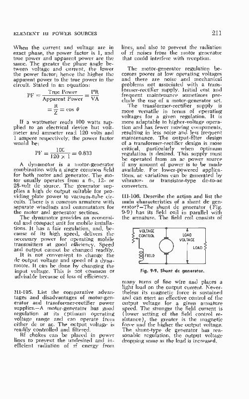
ELEMENT HI POWER SOURCES
When the current and voltage are in exact phase, the power factor is 1, and true power and apparent power are the same. The greater the phase angle be-tween voltage and current, the lower the power factor; hence the higher the apparent power to the true power in the circuit. Stated in an equation:
True Power PR — PF = _ Apparent Power VA
= — = cos O
If a wattmeter reads 100 watts sup-plied to an electrical device but volt-meter and ammeter read 120 volts and 1 ampere respectively, the power factor would be:
10C PF _ — 0.833
1W >s 1
A dynamotor is a motor-generator combination with a sinwe common field for both motor and generator. The mo-tor usually operates from a 6-, 12- or 28-volt de source. The generator sup-plies a high de output suitable for pro-viding plate power to vacuum-tube cir-cuits. There is a common armature with separate windings and commutators for the motor and generator sections. The dynamotor provides an economi-
cal and compact unit for mobile installa-tions. It has a fair regulation, and, be-cause of its high speed, delivers the necessary power for operating mobile transmitters at good efficiency. Speed and output cannot be changed readily.
It is not convenient to change the dc output voltage and speed of a dyna-motor. It can be done by changing the input voltage. This is not common or advisable because of loss of efficiency.
111-105. List the comparative advan-tages and disadvantages of motor-gen-erator and transformer-rectifier power supplies.—A motor-generator has good regulation at its cptimum operating voltage range and can operate from either de or ac. The output voltage is readily controlled and filtered.
Rf chokes can be placed in power lines to prevent the undesired and in-efficient radiation of rf energy from
211
lines, and also to prevent the radiation of rf noises from the motor generator that could interfere with reception.
The motor-generator regulation be-comes poorer at low operating voltages and there are noise and mechanical problems not associated with a trans-former-rectifier supply. Initial cost and frequent maintenance sometimes pre-clude the use of a motor-generator set. The transformer-rectifier supply is
more versatile in terms of operating voltages for a given regulation. It is more adaptable to higher-voltage opera-tion and has fewer moving components, resulting in less noise and less frequent maintenance. The output-filter design of a transformer-rectifier design is more critical, particularly when optimum regulation is desired. This supply must be operated from an ac power source if any amount of power is to be made available. For lower-powered applica-tions, ac variations can be generated by vibrator- or transistor-type dc-to-ac converters.
111-106. Describe the action and list the main characteristics of a shunt dc gen-erator?—The shunt dc generator (Fig. 9-9) has its field coil in parallel with the armature. The field coil consists of
PVOLTAGE ONTROL CD•
IELD
LOAD VOLTAGE
LOAD
Fig. 9-9. Shunt dc generator.
many turns of fine wire and places a light load on the output current. Never-theless its magnetic force is sustained and can exert an effective control of the output voltage for a given armature speed. The stronger the field current is (lower setting of the field control re-sistance), the greater is the magnetic force and the higher the output voltage. The shunt-type dc generator has rea-sonable regulation, the output voltage dropping some as the load is increased.

212 SECOND-CLASS RADIOTELEPHONE LICENSE HANDBOOK
9-4. CHAPTER 9 SELF-TEST
(Answers on page 433)
1. Sulfuric acid in a storage battery A. has no influence on the specific
gravity of the electrolyte. B. is used to clean battery termi-
nals.
2. A silicon rectifier A. requires no filament. B. has good regulation.
3. A synchronous vibrator supply A. is a nonmechanical type. B. is basically an ac-to-dc con- D. has but one set of contacts.
verter.
C.
D.
must be added when specific gravity reads low with full charge. causes the battery to overheat.
C. is capable of handling high currents. D. all of these mentioned.
C. requires no external rectifier.
4. A bleeder resistor must pass 50 mA of current as used in a 650-volt supply. How many watts must the bleeder dissipate? A. 13. C. 16.5. B. 32.5. D. 77.
5. Peak inverse voltage is A. maximum negative voltage ap-
plied to the cathode of a recti-fier.
B. maximum positive voltage ap-plied to the anode of a rectifier.
C. peak voltage applied across the rec-tifier filaments.
D. maximum peak negative voltage ap-plied between anode and cathode.
6. The voltage across the secondary of the power transformer of a full-wave rec-tifier is 500 volts rms. What is the no-load de voltage present on the input capacitor of its filter? A. 705. B. 250.
C. 352. D. 1.414.
7. What is the % regulation of a power supply when full load voltage is 280 volts and no-load voltage is 320? A. 14.2%. C. 8.1%. B. 12.5%. D. 81%.
8. Find the load voltage of a power supply if the regulation is 10%, and the no-load voltage is 600 volts. A. 660. C. 540. B. 560. D. 420.
9. In a swinging choke the inductance A. is always the same. B. swings with the line voltage.
10. A secondary cell A. cannot be recharged. B. has reversible chemical activi-
ties.
11. A dynamotor is an A. ac-to-dc converter. B. dc-to-dc converter.
C. changes inversely with the current. D. decreases with a current drop.
C. has no electrolyte. D. has its plate destroyed by the nor-
mal discharge.
C. dc-to-ac converter. D. none of these mentioned.

ELEMENT Ill POWER SOURCES 213
12. A bridge rectifier, as compared to a full-wave type using the same power transformer, A. has a higher ripple frequency. B. has better regulation.
13. Radio-frequency chokes are often used A. across a battery. B. across the de output terminals
of a power supply.
14. A buffer capacitor is A. used between oscillator and rf
amplifier. B. connected across primary of
power transformer.
C. requires a center-tapped trans-former.
D. provides a higher de output voltage.
C. in motor-generator supply circuits. D. in series with de generator field
winding.
C. a voltage-doubler capacitor D. used to filter out vibrator ac tran-
sients.
The brushes and commutator of a de generator A. act as a rectifier. C. act as a load. B. convert de to ac. D. keep the output constant.
The brushes and commutator of a de motor A. act as a rectifier. C. act as a load. B. convert de to ac. D. keep the output constant.
The voltage across the secondary of the power transformer of a bridge recti-fier system is a A. dc voltage. C. double-frequency pulsating voltage. B. pulsating (le voltage. D. sine wave.
18. Swinging chokes are used in a-m modulator power supplies A. because they boost the voice- C. because of changing modulator load.
frequency lows. D. to remove ripple. B. to eliminate filter capacitors.
19. A bleeder resistor A. can improve power supply regu-
lation. B. is part of swinging choke.
20. A shorted output filter capacitor A. can damage a filter choke. B. increases the dc output voltage.
21. A shorted input filter capacitor can A. damage the rectifier. B. damage the power transformer.
22. Primary cells A. are used in a lead-acid battery. B. use sulfuric acid in the electro-
lyte.
23. The voltage of a iead-acid cell is A. 1.2V. B. 2.1V.
C. D.
C. D.
removes a shock hazard. A and C above.
can (lainage the load. places a high resistance load on the supply.
C. increase the output. D. A and B above.
C. are not rechargeable. D. A and B above.
C. 6.3V. D. 12.6V.

214 SECOND-CLASS RADIOTELEPHONE LICENSE HANDBOOK
24. When the plate of a rectifier is hot it indicates A. an open choke. C. a shorted filter capacitor. B. a short across the load. D. B and C above.
25. As compared to a choke-input filter, a capacitor input filter A. provides better regulation. C. provides a higher current capability. B. gives a higher output voltage. D. A and C above.

CHAPTER 10
Element Ill Amplifiers and Oscillators
10-1. AUDIO AMPLIFIERS
111-107. What are the factors that de-termine the correct bias voltage for the grid of a vacuum tube?—One factor is whether the amplifier is to be biased on the linear portion of its transfer as in class-A, or whether it is to be biased for class-B or class-C operation. The bias voltage must be set in accordance with the desired output. input voltage, per-missible distortion, supply voltage, op-timum load impedance, and so that the performance of' the tube is held within safe operating limits.
111-108. Draw schematic diagrams il-lustrating the follcwing types of grid biasing, and explain the operation of each type: (a) battery, (b) power sup-ply, (c) voltage divider, (d) cathode resistor.—The various bias arrangements are shown in Fig. 10-1.
(a) In the simple battery-biasing ar-rangement, the negative side of the bat-tery connects to the grid, and the posi-tive side connects to the cathode. In operation, other than class-C, there is no significant current through grid resistor 11,, and thus this resistor does not influ-ence grid biasing.
(b) In more elaborate electronic equipment, a separate bias winding on the power transformer or an entirely separate bias-voltage supply may be used. Often the bias-supply bleeder ar-rangement is tapped, which permits va-rious values of bias voltage to be dis-tributed throughout the electronic gear. Taps are selected according to the bias needs of the various tubes.
(c) A voltage-divider arrangement composed of two or more resistors is often used to obtain a specific bias. In this arrangement the bias-supply volt-
age is at some definite and constant voltage. A two-resistor voltage divider is then used to divide this distributed voltage down to the specific value needed by the given tube in the elec-tronic system.
Occasionally instead of using nega-tive voltage applied to the control grid, a voltage divider connected across a positive supply-voltage source will di-vide that voltage down to the proper bias level and supply it as a positive voltage to the cathode. Of course, this is the same as supplying a negative voltage to the control grid, making it negative with respect to the cathode.
(d) The cathode-resistor method of biasing was discussed previously in Chapter 8, Questions III-47 and 111-57. The de component of plate current in the cathode circuit develops the neces-sary bias voltage across the cathode re-sistor with the proper choice of cathode resistor value. In a tetrode or pentode stage it must be remembered that the screen-grid current also is present in the cathode circuit, and the bias value becomes a function of the total cathode current through the cathode resistor.
111-109. Explain how you would deter-mine the approximate value of cathode. bias resistance to provide correct grid bias for any particular amplifier.—In selecting the proper value of cathode resistor it is first necessary to know the exact value of bias that is to be required and the total cathode current when this amount of bias is established. Remem-ber again that for a triode vacuum tube the cathode current is equal to the plate current. In tetrode and pentode tubes the cathode current is equal to the sum of the plate current and the screen-grid current.
215

216 SECOND-CLASS RADIOTELEPHONE LICENSE HANDBOOK
LEE
(A) Battery biasing.
\ SEPARATE WINDING ON POWER TRANSFORMER
(B) Bias power supply.
-Ecc
- EBB •
_ EBB
6 OPTIONAL DIVIDER •V PLAN
VOLTAGE DIVIDER RESISTORS
(C) Voltage divider.
CATHODE BIAS RESISTOR
Ng
- EBB
(D) Cathode resistor.
Fig. 10-1. Bias arrangements.
When the desired bias and cathode current have been selected according to the manufacturer's ratings or charac-teristic curves and the desired operat-ing conditions, Ohm's law can be used to determine the ohmic value of the cathode resistor. For example, if the de-sired grid bias is —3 volts and the total de cathode current is 2.5 milliamperes, the ohmic value of the cathode resistor becomes:
—3 Rk 0.0025 = 1200 ohms
lk
The power that must be dissipated by this resistor can be obtained with a sec-ond simple calculation:
P=E x I=3 X 0.0025 = 0.0075 watts
III-110. Is grid-leak biasing practical in audio-amplifier stages?—No. This type of biasing is not used because in Yr normal linear operation of vacuum tubes there is no grid current. Thus no signifi-cant voltage can be developed across the grid resistor. If an operating point and signal amplitude were selected so that there would be grid current, it would result in distortion and, in most cases, improper loading of the preced-ing audio stage. Grid-leak biasing, how-ever, is a common method of obtaining negative grid voltage for class-C rf am-plifiers and oscillators.
III-111. Draw a diagram showing a method of obtaining grid bias for a filament-type vacuum tube by the use of resistance in the plate circuit of the tube.—This technique is shown in Fig. 10-2. In such an arrangement the nega-tive side of the plate-voltage supply
EBB
Fig. 10-2. Biasing a tube from the plate circuit resistor.
returns to ground through a bias-resistor combination. The control grid is re-turned to the junction of the resistor and the negative side of the plate volt-age supply.
111-112. Draw simple schematic dia-grams illustrating the following types of coupling between audio-amplifier stages, and between a stage and a load: (a) triode vacuum tube induc-tively coupled to a speaker, (b) re-sistive coupling between two pentode vacuum tubes, (c) impedance coupling between two tetrode vacuum tubes, (d) a method of coupling a high-im-pedance speaker to an audio-frequency audio-amplifier tube without plate cur-rent going through the speaker wind-ing, and without the use of a trans-former.—Refer to Fig. 10-3.

ELEMENT III AMPLIFIERS AND OSCILLATORS
O _ EBB
(A) Inductive coupling to a speaker.
(B) Resistance-coup ed stages.
(C) Impedance coupling.
(D) Coupling to a high-impedance speaker.
Fig. 10-3. Coupling systems.
III-113. Draw circuit diagrams and ex-plain the operation (include input-output phase relationships, approximate practical voltage gain, approximate stage efficiency, uses, advantages, and limitations) of each of the following types of audio circuits: (a) class-A am-plifier with cathode-resistor biasing, (b) cathode-follower amplifier, (c) at least two types of phase inverter for feeding push-pull amplifiers, (d) cas-
217
caded class-A stages with a form of current feedback, (e) two class-A am-plifiers operated in parallel, (f) class-A push-pull amplifier.—( a ) A class-A am-plifier with cathode-resistor biasing was discussed in Chapter 8, Question HI-47 and Fig. 8-10. Input and output volt-ages are 180* out of phase. Practical voltage gains extend from below 10 up to in excess of 100. Practical efficiencies fall between 10% and 30% with a theo-retical maximum of 50%. Such stages can be used as audio-amplifiers and, with appropriate compensating circuits, as video amplifiers.
In conjunction with resonant circuits instead of resistive loads, they can func-tion as radio-frequency amplifiers. When operated correctly they serve as linear amplifiers. Maximum voltage gain can be ob-
tained when such stages are employed as small-signal amplifiers. As the signal level becomes higher and higher, there is a corresponding reduction in the practical value of voltage gain that can be obtained. ( b) The circuit and general operation
of a cathode-follower was covered in Chapter 8, Question 111-47 and Fig. 8-13. The cathode-follower is limited to a voltage gain of less than 1. Input and output voltages are in phase. A major use for a cathode follower is to match a high impedance to a low impedance; it serves as an effective impedance trans-former with a wideband frequency re-sponse. The cathode-follower has a high input impedance and a low input ca-pacitance. Consequently a cathode fol-lower can be used where a very light load is to be placed on the preceding stage.
(c) The two most popular forms of phase inverters are shown in Fig. 10-4. The purpose of a phase inverter is to obtain as nearly as possible equal-ampli-tude and opposite-polarity signals for application to a push-pull amplifier. The split-load inverter (Fig. 10-4A) uses both plate and cathode output. The plate output is of course 180* out of phase with the input wave, while the cathode output is in phase with the in-put voltage. As a result, the opposite-polarity condition is met. By equalizing the ohmic values of plate-load resistor and cathode resistor, the amplitude can also be made essentially the same. Am-plifier gain is limited to less than unity. The two output impedances differ, and, therefore, the coupling system must be designed properly to make certain that

218 SECOND-CLASS RADIOTELEPHONE LICENSE HANDBOOK
essentially equal-amplitude components over the desired frequency range are delivered to the next stage. The second phase-inverter arrange-
ment (Fig. I0-4B) uses two triode sec-tions. It provides gain along with required equal-amplitude and opposite-polarity components. Output imped-ances, too, are essentially the same for both sources of signal. The top tube (V1) is connected as a class-A resist-ance-coupled amplifier. It develops a signal component which is out of phase with the input wave. A portion of this output signal is taken off across the output voltage-divider resistors, RI and R2. The weaker voltage variation is connected to the grid-cathode circuit of the lower class-A amplifier tube, V2. The voltage divider reduces its level to approximately the same magnitude as the original input wave. An amplified component appears at the plate circuit of V2. Because of the additional polar-ity shift of V2, the output signal is brought back in phase with the input wave. By proper choice of load divider, its magnitude at the output at V2 can be made the same as that present at the plate circuit of VI. In this case, ampli-fied equal-amplitude and opposite-po-larity signals are made available for driving a following push-pull stage. Both of the phase inverters are funda-mentally voltage-amplifier stages. They are designed to operate into a high im-
,P (—°PUSH-PULL
INPUT
-4 —C>
(A)
'Be .
Split-load type.
(B) Two-tube type.
Fig. 10-4. Phase inverters.
pedance. They are not usable when the following push-pull stage requires a significant amount of driving power.
(d) Two resistance-coupled stages with current feedback are shown in Fig. 10-5. The total gain of the two-stage amplifier is the product of the individ-ual stage gains. Less gain is possible when feedback is used. However, feed-back stabilizes the amplifier operation, maintaining a constant and uniform gain over a desired audio-frequency range. Negative feedback also reduces nonlinear distortion. In feedback sys-tems, the feedback may be proportional to either the output voltage or the out-put current. When proportional to the output voltage, the feedback is called voltage feedback; when proportional to the output current, it is called cur-rent feedback.
VI
_ EB8
EBB
CURRENT
FEEDBACK
Fig. 10-5. Two-stage amplifier with current feedback.
The output load is the source of cur-rent feedback which is proportional to the current in that load. To obtain neg-ative feedback, it is of course necessary that the feedback voltage be out of phase (opposite polarity) relative to the signal voltage at the point where the feedback is inserted, as shown in Fig. 10-5. The phasing relationship can be veri-
fied when one considers that plate out-put is of opposite polarity from the in-put signal, while the cathode output is of the same polarity as the input sig-nal. Note that the plate output of VI is of opposite polarity with respect to the input to VI. However, the plate output of V2 has the same phase as the input of VI. As a result, when it is re-introduced into the cathode circuit of the first tube it is of the same polarity as the grid-input wave. Therefore it is degenerative and provides negative feedback.
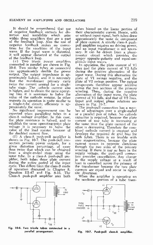
ELEMENT III AMPLIFIERS AND OSCILLATORS
It should be remembered that use of negative feedback corrects for dis-tortion and instability which arise within those amplifiers that are a part of the feedback loop. Also the use of negative feedback makes no correc-tions for the condition of the input wave. If the input wave is distorted, it will appear distorted at the output of the feedback loop. ( e) Two triocie power amplifiers
connected in paraliel are shown in Fig. 10-6. Two similar tubes so connected can approximately double the power output. The output impedance is ap-proximately halved, and it is necessary that the transformer primary carry twice the current normal for a single-tube stage. The cathode current also is higher, and to obtain the same operat-ing bias it is necessary to halve the value of the cathode resistor. In other respects its operation is quite similar to a single-tube circuit; efficiency is ap-proximately the same. No significant improvement can be
expected when paralleling tubes in a class-A voltage amplifier. In this case, the plate resistance is halved, and to establish the same operating-point plate voltage it is necessary to halve the value of the load resistor because of the doubled current flow.
(f) A class-A push-pull amplifier is shown in Fig. 10-7. The push-pull con-nection permits power outputs, for a given distortion percentage, of more than twice that which can be obtained from a single-ended stage using the same tube. In a class-A push-pull am-plifier, both tubes draw plate current during the entire period of the input cycle. This differs from the class-B mode of operation discussed in Chapter 8, Question III-47 and Fig. 8-14. The Class-A push-pull amplifier sees both
TO LOAD
Fig. 10-6 Two triode tubes connected in a parallel arrangement.
219
tubes biased on the linear portion of their characteristic curves. Hence, with or without input signal, both tubes draw approximately the same de component of plate current. A strictly class-A push-pull amplifier requires no driving power, and an input transformer is not neces-sary. It can be driven from a phase-inverter circuit which provides the proper opposite-polarity and equal-am-plitude input waves.
In operation, the plate current of VI rises and the plate current of V2 falls during the positive alternation of the input wave. During this alternation the plate of VI swings negative, and the plate of V2 swings positive. The output components therefore appear additive across the two sections of the primary winding. Then, during the negative alternation of the input wave, the plate current of VI falls, and that of V2 rises. Input and output phase relations are shown in Fig. 10-7. The push-pull connection has a num-
ber of advantages over a single-ended or a parallel pair of tubes. No cathode capacitor is required, because the plate current of one tube is increasing at the same time the plate current of the other is decreasing. Therefore the com-bined cathode current is constant and develops the required de grid bias for both tubes. There is no trouble with core magnetization, because the plate current occurs in opposite directions through the two sides of the primary winding. If there is any ac hum in the supply voltage, the push-pull connec-tion provides cancellation. Any change in the supply voltage as a result of hum is cancelled across the primary of the transformer because the two plate currents are equal and occur in oppo-site directions. When the amplifier is operating on
the nonlinear portion of a tube trans-
VI
FROM PHASE I NVERIER LOAD
Fig. 10-7. Push-pull class-A amplifier
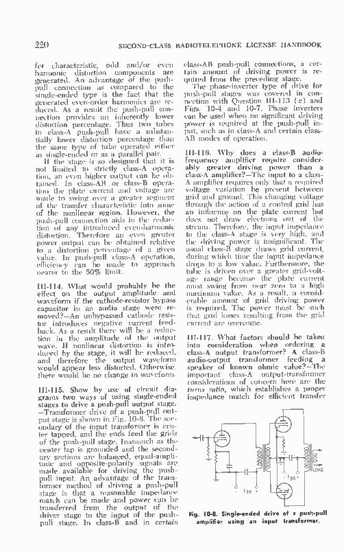
000 SECOND-CLASS RADIOTELEPHONE LICENSE HANDBOOK
fer characteristic, odd and/or even harmonic distortion components are generated. An advantage of the push-pull connection as compared to the single-ended type is the fact that the generated even-order harmonics are re-duced. As a result the push-pull con-nection provides an inherently lower distortion percentage. Thus two tubes in class-A push-pull have a substan-tially lower distortion percentage than the sanie type of tube operated either as single-ended or as a parallel pair.
If the stage is so designed that it is not limited to strictly class-A opera-tion, an even higher output can be ob-tained. In class-AB or class-B opera-tion the plate current and voltage are made to swing over a greater segment of the transfer characteristic into some of the nonlinear region. However, the push-pull connection aids in the reduc-tion of any introduced even-harmonic distortion. Therefore an even greater power output can be obtained relative to a distortion percentage of a given value. In push-pull class-A operation, efficiency can be made to approach nearer to the 50% limit.
III-114. What would probably be the effect on the output amplitude and waveform if the cathode-resistor bypass capacitor in an audio stage were re-moved?—An unbypassed cathode resis-tor introduces negative current feed-back. As a result there will be a reduc-tion in the amplitude of the output wave. If nonlinear distortion is intro-duced by the stage, it will be reduced, and therefore the output waveform would appear less distorted. Otherwise, there would be no change in waveform.
III-115. Show by use of circuit dia-grams two ways of using single-ended stages to drive a push-pull output stage. —Transformer drive of a push-pull out-put stage is shown in Fig. 10-8. The sec-ondary of the input transformer is cen-ter tapped. and the ends feed the grids of the push-pull stage. Inasmuch as the center tap is grounded and the second-ary sections are balanced, equal-ampli-tude and opposite-polarity signals are made available for driving the push-pull input. An advantage of the trans-former method of driving a push-pull stage is that a reasonable impedance match can be made and power can be transferred from the output of the driver stage to the input of the push-pull stage. In class-B and in certain
class-AB push-pull connections, a cer-tain amount of driving power is re-quired from the preceding stage. The phase-inverter type of drive for
push-pull stages was covered in con-nection with Question III-113 ( c) and Figs. 10-4 and 10-7. Phase inverters can be used when no significant driving power is required at the push-pull in-put, such as in class-A and certain class-AB modes of operation.
111-116. Why does a class-B audio-frequency amplifier require consider-ably greater driving power than a class-A amplifier?—The input to a class-A amplifier requires only that a required voltage variation be present between grid and ground. This changing voltage through the action of a control grid has an influence on the plate current but does not draw electrons out of the stream. Therefore, the input impedance to the class-A stage is very high, and the driving power is insignificant. The usual class-B stage draws grid current, during which time the input impedance drops to a low value. Furthermore, the tube is driven over a greater grid-volt-age range because the plate current must swing from near zero to a high maximum value. As a result, a consid-erable amount of grid driving power is required. The power must be such that grid losses resulting from the grid current are overcome.
111-117. What factors should be taken into consideration when ordering a class-A output transformer? A class-B audio-output transformer feeding a speaker of known ohmic value?—The important class-A output-transformer considerations of concern here are the turns ratio, which establishes a proper impedance match for efficient transfer
Fig. 10-8. Single-ended drive of a push-pull amplifier using an input transformer.
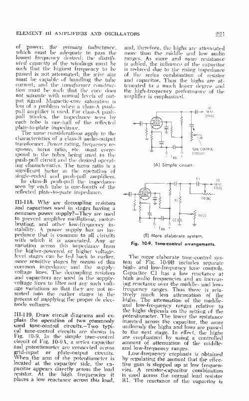
ELEMENT III AMPLIFIERS AND OSCILLATORS
of power; the primary inductance, which must be adequate to pass the lowest frequency desired; the distrib-uted capacity of the windings must be such that the highest frequency to be passed is not attenuated; the wire size must be capable of handling the tube current; and the transformer construc-tion must be such that the core does not saturate with normal levels of out-put signal. Magnetic-core saturation is less of a problem when a class-A push-pull amplifier is used. For class-A push-pull triodes, the impedance seen by each tube is one-half of the reflected plate-to-plate impedance. The same considerations apply to the
characteristics of a class-B audio-output transformer. Power rating, frequency re-sponse, turns ratio, etc. must corre-spond to the tubes being used in the push-pull circuit and the desired operat-ing characteristics. The turns ratio is a significant factor in the operation of single-ended and push-pull amplifiers.
In class-B push-pull the impedance seen by each tube is one-fourth of the reflected plate-to-piate impedance.
111-118. Why are decoupling resistors and capacitors used in stages having a common power supply?—They are used to prevent amplifier oscillations, motor-boating, and other low-frequency in-stability. A power supply has an im-pedance that is common to all circuits with which it is associated. Any ;lc variation across this impedance from the higher-powered or higher voltage-level stages can be fed back to earlier, more sensitive stages by means of this common impedance and the supply-voltage lines. The decoupling resistors and capacitors are used in the supply-voltage lines to filter out any such volt-age variations so that they are not in-serted into the earlier stages in the process of supplying the proper de elec-trode voltages.
III-119. Draw circuit diagrams and ex-plain the operation of two commonly used tone-control circuits.—Two typi-cal tone-control circuits are shown in Fig. 10-9. In the simple tone-control circuit of Fig. 10-9A, a series capacitor and potentiometer are connected across grid-input or plate-output circuits. When the arm of the potentiometer is located at the capacitor side, the ca-pacitor appears directly across the load resistor. At the high frequencies it places a low reactance across this load,
221
and, therefore, the highs are attenuated more than the middle and low audio ranges. As more and more resistance is added, the influence of the capacitor is reduced due to the rising impedance of the series combination of resistor and capacitor. Thus the highs are at-tenuated to a much lesser degree and the high-frequency performance of the amplifier is emphasized.
TO NIXI STAGE
\
TONE CONTROL CIRCUIT
- EBB
(A) Simple circuit.
- EBB (B) More elaborate system
Fig. 10-9. Tone-control arrangements.
CI To i v AT :T
STAGE
TREBLE
/ BASS
The more elaborate tone-control sys-tem of Fig. 10-9B includes separate high- and low-frequency tone controls. Capacitor Cl has a low reactance at high audio frequencies and an increas-ing reactance over the middle- and low-frequency ranges. Thus there is rela-tively much less attenuation of the highs. The attenuation of the middle-and low-frequency ranges relative to the highs depends on the setting of the potentiometer. The lower the resistance inserted across the capacitor, the more uniformly the highs and lows are passed to the next stage. In effect, the highs are emphasized by using a controlled amount of attenuation of the middle-and low-frequency ranges.
Low-frequency emphasis is obtained by regulating the amount that the effec-tive gain is stepped up at low frequen-cies. A resistor-capacitor combination is used across the normal load resistor RI. The reactance of the capacitor is

222 SECOND-CLASS RADIOTELEPHONE LICENSE HANDBOOK
high at low frequencies, and therefore the series impedance of resistor RI and capacitor C2 is high. Over the middle-and high-frequency ranges, the react-ance of the capacitor is low, and the impedance is determined mainly by the resistance of RI. Therefore the stage gain is lower at the mid- and high-frequency ranges. The extent to which the lows are boosted depends on the setting of the potentiometer. The lower the resistance that it shunts across the capacitor, the more uniform is the gain over the audio-frequency range. The lows are emphasized by placing maxi-mum resistance across C2.
IH-120. Why do vacuum tubes produce random noises?—Although there are several types of noises generated within a vacuum tube, the most pronounced are the so-called shot-effect noise com-ponents. These are generated by the nonuniformity of the emission from a cathode surface, resulting in minute fluctuations in plate and other electrode currents. This particular random fluctu-ation along with other much lower-level tube noises are referred to as vacuum-tube random noise.
III-121. Name some causes of hum and self-oscillation in audio amplifiers. Give the methods for reducing them.—Self-oscillation is produced by positive feed-back which can occur between the in-put and output of an individual stage, or between the output of a higher-volt-age or power-level stage and the more sensitive lower-level input stage of an amplifier. Individual stage feedback is reduced by proper circuit design and adequate isolation between input and output circuits. The use of tetmde and pentode tubes reduces the possibility of individual stage oscillations. Neutraliz-ing capacitors and other types of neu-tralizing circuits can be used to cancel feedback by introducing a controlled amount of feedback of the opposite po-larity, minimizing the tendency of a stage to self-oscillate. In an amplifier it is important that there be a proper iso-lation between high-level output and sensitive input stages. Shielding and the in-line construction of stages as well as the complete isolation of output and input leads remove those conditions which encourage oscillations. Decoup-ling capacitors and resistors and special filter circuits also reduce the oscillation tendency. Low-impedance circuits at certain critical points in an amplifier
can do much to overcome any tendency to oscillation. Hum in an amplifier can be a result
of inadequate filtering of the de supply voltage, or hum that leaks from ac fila-ment lines into the high-gain sensitive-input stages of an amplifier. Hum can be reduced by providing adequate power-circuit filtering and proper de-coupling of supply-voltage lines. Feed lines should be routed carefully and properly balanced and bypassed. In some cases the early stages of a very high-gain amplifier may employ de fila-ment voltage. Push-pull circuits are less subject to the influence of hum. Hum can result from undesired ca-
pacitive or inductive coupling. Trans-formers should be well constructed and shielded and should be mounted in a manner that keeps them isolated from signal leads and sensitive stages. Signal-input leads and any leads that carry signal over other than a short path be-tween one stage and the next should be of a shielded low-impedance type which is much less subject to hum and noise pick-up. Possible sources of hum should be kept well isolated from input lines and high-gain input stages so as to mini-mize both inductive and capacitive coupling of hum into the signal path.
III-122. How would saturation of an output transformer create distortion?— Output-transformer saturation causes the transformer to respond in a non-linear manner to the amplitude changes of an applied signal. As a result there is an introduction of harmonic distortion. Transformer-core saturation causes flat-tening of the high-amplitude portions of an applied strong signal.
III-123. Why is noise often produced when an audio signal is distorted?—Any nonlinearity in the tubes or other com-ponents of an amplifier will distort an audio signal. In the process, both har-monic- and intermodulation-distortion components are generated. The former are in the form of harmonics, second, third, fourth, fifth, etc., of the original wave. The latter components result from mixing activities among two or more of the audio frequencies that com-prise the original audio signal, and pos-sibly their harmonics. These spurious signals of various frequencies are carried along with the desired signals. Inas-much as they are frequency compo-nents that did not exist in the original

ELEMENT III AMPLIFIERS AND OSCILLATORS
signal (noise), they tend to raise the background noise level of the signal.
III-124. Draw a diagram of a single-button carbon microphone circuit, in-cluding the microphone transformer and source of power.—Such a micro-phone and associated circuit are shown in Fig. 10-10.
STEP-UP TRANSFORMER
MICROPHONE
1 MI KE SWITCH
BUTTON CONTAINER OF
CARBON GRANULES
TO GR ID OF AMPLIFIER
TUBE
Fig. 10-10. Carbon-microphone circuit.
III-125. Describe the construction and explain the operation of a crystal-type microphone; a carbon-button micro-phone.—The carbon microphone (Fig. 10-10) consists of a small container filled with carbon granules (referred to as a carbon button) attached to a dia-phragm. As the sound vibrations strike the diaphragm they cause a varying pressure on the button. The carbon granules compress and expand in step with this pressure. resulting in a re-sistive change which influences the cur-rent in the external circuit. This external circuit consists of a source of de voltage and the primary of a microphone trans-former. The current variation in the pri-mary of the microphone transformer in-duces a similar changing voltage into the secondary.
In summary, the changing sound pressure causes a ,,ariation in the mi-crophone current. These variations are stepped up by the transformer and ap-pear as an audio voltage across the secondary.
Sometimes the carbon granules pack tightly, cutting down on the output and increasing the noise. Usually they can be shaken loose. The crystal microphone operates on
the piezoelectric principle, in which cer-tain crystals, such as Rochelle salt, de-velop an output voltage when subjected to a mechanical pressure. When sound vibrations are applied to a diaphragm linked mechanically to such a crystal (Fig. 10-11), the variations of mechani-cal pressure cause the crystal to gener-ate an output voltage that follows the
DIAPHRAGM
MECHANI CAL COUPE ING
223
PIEZOELECTRIC SLABS
Fig. 10-11. Crystal microphone.
sound change. Another version of a crystal microphone uses a number of very small crystal elements which in themselves serve as a diaphragm. The individual outputs are combined to de-velop the total output of the micro-phone.
Crystal and carbon microphones are sensitive and develop a strong output. The crystal microphone has a high-output impedance compared to the car-bon type, but it has a better frequency response.
III-12G. What precautions should be observed when using and storing crystal microphones?—It is advisable to store a crystal microphone in a cool, dry loca-tion because of its susceptibility to en-vironmental extremes, in particular, to extremes of high temperature and high humidity.
III-127. If low-impedance headphones on the order of 75 ohms are to be con-nected to the output of a vacuum-tube amplifier, how may this be done to per-mit most satisfactory operation?—The preferred method is to use an audio transformer with a step-down imped-ance ratio. In this manner the rather low impedance of the headphones can be matched to the higher impedance of the amplifier, providing a proper load for the operation of the vacuum tube and the optimum transfer of signal from its output to the headphone.
10-2 RADIO-FREQUENCY AMPLIFIERS
III-128. What is the difference between rf voltage amplifiers and rf power am-plifiers with regard to applied bias? What kind of tube is generally em-ployed in rf voltage amplifiers?—Rf voltage amplifiers are used extensively in receivers and less frequently in transmitters. They are to be found in single-sideband transmitters. Rf voltage amplifiers are usually biased class-A and

224 SECOND-CLASS RADIOTELEPHONE LICENSE HANDBOOK
operate over the linear segment of their transfer characteristics. The pentode is the most common tube used in rf volt-age amplifiers although, on occasion, in the earlier stages of a receiver, advan-tage is taken of the low-noise charac-teristics of a triode.
Rf power amplifiers are usually oper-ated class-B or class-C. A typical class-C power amplifier is shown in Fig. 10-12. It includes input and output resonant circuits, which in the case of a straight-through or fundamental-frequency rf amplifier, are tuned to the same fre-quency. The beam-power tube is the most common rf power amplifier, al-though a number of pentodes and some triodes are used in this function. In most instances, with appropriate circuits and tubes, there is no need for neutralizing a beam-power or pentode tube.
In a class-C stage the tube draws plate current only during the most posi-tive portion of the positive alternation of the input wave. Thus the plate cur-rent is drawn in bursts of high-peak value. Such a burst supplies a lot of electrical energy into the plate resonant-tank circuit, and the capacitor is charged to a high negative value ( sharp drop in plate voltage). However, a resonant circuit has smoothing and energy-storing ability. When the plate current burst ceases, the charge on the
Cg %
MAXIMUM AT RESONANCI
CUT OFF
DIPS AT RESONANCE
INPUT
PLATE f\_GURREèf\__i
GRID I CURRENT\___
TANK VOLTAGE
Fig. 104 2. Basic class-C amplifier.
capacitor begins to fall off and energy is transferred to the coil. After the charge reaches zero, the collapsing field of the coil releases its stored energy back into the tank circuit. An opposite flow of current results and charges the capacitor in the opposite polarity even though the plate current has stopped.
The magnetic field about the coil is now of opposite direction. When the capacitor loses its peak charge, the magnetic field again collapses, and a new cycle of original polarity begins.
Soon afterwards, a new burst of plate current is introduced because of the positive swing of the grid waveform, and the plate tank-circuit capacitor is again charged to a maximum negative value, initiating a new cycle of opera-tion. Although the rf amplifier operates class-C and plate current does not occur for the full cycle of the input wave, a good sine wave is developed across the plate tank circuit, with the proper choice of LC constants and load.
In most rf power amplifiers, the class-C bias is developed by the grid current in the grid circuit. On the positive peak of the input wave there is a substantial amount of grid current, which develops a negative charge on grid capacitor C,. The current is such that the charge placed on the capacitor biases the tube beyond cutoff. Between intervals of grid current, the charge leaks off the capaci-tor through resistor R,. If the time con-stant of R,C, is high enough, a reason-ably constant bias will be retained dur-ing the entire cycle of the input wave. This is equivalent to a de bias voltage of a value that is several times beyond cutoff. Of course, the capacitor is re-stored to full charge by the grid current at the crest of each positive input wave. The grid current is often measured
with a (lc meter. Such a meter is useful in tuning a class-C stage. There is maxi-mum de grid current when the applied input wave is peaked at its maximum amplitude. A de meter is often used in the plate circuit (or in the cathode cir-cuit) to measure the dc plate current. This reading is also useful in tuning a class-C stage. When a plate resonant circuit is tuned to resonance, it dis-plays a maximum impedance, and the de plate current "dips" to a minimum. As energy is withdrawn to a load, more power must be supplied to the tank cir-cuit, and there will be a rise in the de plate current reading. One of the hazards of using self-bias
in operation of a class-C amplifier re-
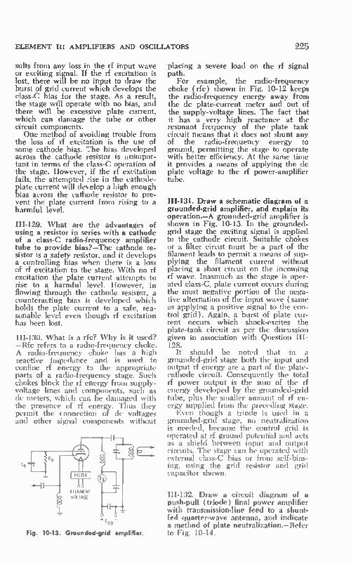
ELEMENT III AMPLIFIERS AND OSCILLATORS
suits from any loss in the rf input wave or exciting signal. If the rf excitation is lost, there will be no input to draw the burst of grid current which develops the class-C bias for the stage. As a result, the stage will operate with no bias, and there will be excessive plate current, which can damage the tube or other circuit components. One method of avoiding trouble from
the loss of rf excitation is the use of some cathode bias. The bias developed across the cathode resistor is unimpor-tant in terms of the class-C operation of the stage. However, if the rf excitation fails, the attempted rise in the cathode-plate current will develop a high enough bias across the cathode resistor to pre-vent the plate current from rising to a harmful level.
III-129. What are the advantages of using a resistor in series with a cathode of a class-C radio-frequency amplifier tube to provide bias?—The cathode re-sistor is a safety resistor, and it develops a controlling bias when there is a loss of if excitation to the stage. With no rf excitation the plate current attempts to rise to a harmful level. However, in flowing through the cathode resistor, a counteracting bias is developed which holds the plate current to a safe, rea-sonable level even though rf excitation has been lost.
HI-130. What is a ríe? Why is it used? —Rfc refers to a radio-frequency choke. A radio-frequency choke has a high reactive impedance and is used to confine if energy to the appropriate parts of a radio-frequency stage. Such chokes block the rf energy from supply-voltage lines and components, such as de meters, which can be damaged with the presence of rf energy. Thus they permit the connection of de voltages and other signal components without
FILAMENT VOLTAGE
Fig. 10-13. Grounded-grid amplifier.
225
placing a severe load on the rf signal path.
For example, the radio-frequency choke (rfc) shown in Fig. 10-12 keeps the radio-frequency energy away from the de plate-current meter and out of the supply-voltage lines. The fact that it has a very high reactance at the resonant frequency of the plate tank circuit means that it does not shunt any of the radio-frequency energy to ground, permitting the stage to operate with better efficiency. At the same time it provides a means of applying the de plate voltage to the rf power-amplifier tube.
III-131. Draw a schematic diagram of a grounded-grid amplifier, and explain its operation.—A grounded-grid amplifier is shown in Fig. 10-13. In the grounded-grid stage the exciting signal is applied to the cathode circuit. Suitable chokes or a filter circut must be a part of the filament leads to permit a means of sup-plying the filament current without placing a short circuit on the incoming rf wave. Inasmuch as the stage is oper-ated class-C, plate current occurs during the most negative portion of the nega-tive alternation of the input wave ( same as applying a positive signal to the con-trol grid). Again, a burst of plate cur-rent occurs which shock-excites the plate-tank circuit as per the discussion given in association with Question III-128.
It should be noted that in a grounded-grid stage both the input and output if energy are a part of the plate-cathode circuit. Consequently the total rf power output is the sum of the if energy developed by the grounded-grid tube, plus the smaller amount of rf en-ergy supplied from the preceding stage. Even though a triode is used in a
grounded-grid stage, no neutralization is needed, because the control grid is operated at if ground potential and acts as a shield between input and output circuits. The stage can be operated with external class-C bias or from self-bias-ing, using the grid resistor and grid capacitor shown.
III-132. Draw a circuit diagram of a push-pull (triode) final power amplifier with transmission-line feed to a shunt-fed quarter-wave antenna, and indicate a method of plate neutralization.—Refer to Fig. 10-14.

196
RFC
SECOND-CLASS RADIOTELEPHONE LICENSE HANDBOOK
Si4 ANTENNA
FARADAY SHIELD
RFC
TRANSMISSION LINE
Fig. 10-14. Push-pull amplifier with plate cross-neutralization and grounded quarter.
wave antenna
HI-133. Explain the principle involved in neutralizing an rf stage.—A class-C amplifier self-oscillates when enough in-phase rf energy is fed back from the output circuit to the input circuit. The path that the feedback energy takes is through the interelectrode capacitances of the tube, mainly the plate-grid ca-pacitance (Cg„). One method of pre-venting self-oscillation is to feed back from the plate circuit another compo-nent which will cancel out the feedback component that causes self-oscillation. Such an arrangement is shown in Fig. 10-15. The component fed back through neutralizing capacitor C. is of opposite polarity from that feed back to the grid circuit through the interelectrode ca-pacitance. By regulating carefully the size of capacitor C., the neutralizing component can be made of equal am-plitude and opposite polarity from that which is fed back through the tube capacitance. One can also consider a neutraliza-
tion system as a balanced bridge. When the bridge is adjusted, the rf currents in the inductive and capacitive legs are balanced. Hence there is no difference of rf potential between grid and cath-ode as a result of the feedback currents.
III-134. Explain step by step at least one procedure for neutralizing an rf amplifier stage.—In the neutralization process the tuning objective is to mini-mize the net transfer of energy from the plate circuit back to the grid circuit of the stage. In most neutralization systems a converse plan is used in performing the actual neutralization procedure. The neutralization process is mainly accom-
plished by minimizing the amount of input signal that is transferred to the output tank when no plate supply volt-age is supplied to the stage. Any such input signal must travel over the same path to the output as output signal would travel to input without neutrali-zation. Thus, if we make the necessary adjustments to minimize the transfer of sig.nal from input to output, we have in effect also minimized the possibility of the transfer of signal from output to in-put. Thus in neutralizing a stage, the normal rf excitation is applied to the grid of the stage to be neutralized.
PLATE
C9P
GRID
L2 TOP
CATHODE
L2 BOTTOM
Fig. 10-15. Plate-neutralization system.
However, note that no power except filament power is supplied to that stage. A step-by-step procedure as applied
to the circuit of Fig. 10-15, is as fol-lows:
1. Place the filament circuit in opera-tion, but turn off the plate voltage (screen voltage also if it is a multi-grid tube).

ELEMENT III AMPLIFIERS AND OSCILLATORS
2. Supply the ncrmal rf signal to the control-grid circuit of the stage. If the stage is being neutralized for the first time, set the neutralizing capaci-tor to one extreme of its range. Let us assume that it has been set to maximum capacitance. 3. Resonate the grid tuned circuit for maximum rf ex2itation as indicated by a maximum reading on the dc grid-current meter (I,,). 4. Tune the plate tank capacitor over its range. If the stage is not neutral-ized, the grid-current meter reading will jump whenever the plate tank circuit is tuned through resonance. Likewise, there will be an indication of output whet: a sensitive rf indi-cator is placed close to the plate tank coil. 5. Decrease slightly the capacitance of the neutralizing capacitor. Tune the plate tank circuit through reso-nance again, and note the kick of the needle. Continue to decrease the set-ting of the neutralizing capacitor until there is a minin-um kick of the needle and a minimum rf output when the plate tank capacitor is tuned through resonance. 6. If the neutralizing capacitance is decreased too far, the rf output and grid kick will increase. There is just one optimum setting for the neutral-izing capacitor, and it must not exert too little or too much capacitance into the path. 7. The stage is properly neutralized if the plate tank capacitor can be tuned through resonance without changing the grid-current reading. The actual procedure is an attempt to find the setting of the neutralizing capacitor which will give no or very little grid-current meter deflection. 8. Place some load on the output. Apply the power to the stage at re-duced voltage. Tune the plate tank circuit for a resonant dip, using me-ter Li. Finally, the full plate voltage can be applied, and the plate tank circuit and output coupling are ad-justed for optimum operation.
11-135. State some indications of the presence of parasitic oscillations in a transmitter. Give some methods of sup-pressing them.—Parasitic oscillations are undesired oscillations in an rf amplifier stage. They are self-excited, usually at some frequency quite removed from the desired operating frequency of the am-plifier. They are often indicated by the
227
presence of rf energy in a stage, even though the rf excitation from the pre-ceding stage has been removed. They are indicated when a signal can be picked up on a receiver tuned to some remote frequency when the transmitter is in operation. Meter readings are high or erratic.
Usually the presence of parasitics makes it difficult to tune a stage for op-timum performance, or the tuning and operation of the stage seems to be er-ratic. The stability and efficiency of the stage are harmed with the presence of parasitics. Their presence in a modu-lated amplifier can have an adverse ef-fect on the modulation quality or make it extremely difficult to tune for an op-timum modulation characteristic. Para-sitics in a stage that amplifies a modu-lated rf signal can introduce distortion components into the modulation.
In summary, parasitic oscillations can make themselves evident as self-oscilla-tion when rf excitation is removed, in-stability, difficult tuning, poor efficiency, and the introduction of distortion com-ponents. A sensitive rf indicator can be used to
track down parasitic oscillations after the removal of the normal rf excitation from the stage. A grid-dip meter can even be used to make an approximate frequency measurement of the parasitic oscillations. Usually they occur at a very low frequency (several hundreds of kilohertz) as caused by radio-fre-quency choices, capacitors, and other circuit components, or at a vhf fre-quency where they can be caused by lead lengths, stray capacitances, and cir-cuit components. Changes in circuit wiring and rearrangement of compo-nents are often necessary to stop these parasitics. Parasitic chokes and resistors are also available and are very effective in the suppression of the undesired self-oscillations.
III-136. Draw a schematic diagram and explain the operation of a harmonic-generator stage.—A typical harmonic generator is shown in Fig. 10-16. Triode or multigrid tubes can be used as har-monic generators. The beam-power tube is very common because of its low driv-ing power and capability of generating a strong harmonic output. No neutrali-zation is necessary, because the output plate tank circuit is tuned to a fre-quency different from the input signal. It is tuned to the second, third, or higher harmonics of the input fre-

228 SECOND-CLASS RADIOTELEPHONE LICENSE HANDBOOK
quency, depending on the desired out-put frequency. The harmonic generator is operated
class-C. In fact, to obtain a strong har-monic output the generator is often op-erated even further beyond cutoff than a normal straight-through class-C am-plifier. To some extent, the desired har-monic, second, third, fourth, etc., de-termines the most favorable operating angle for the stage. (This refers to the number of degrees or portion of the in-put wave during which there is plate current.) In general, the sharper the plate current burst, the stronger is ifs harmonic content. However, efficiency is also a factor in selecting the proper beyond-cutoff bias.
If the harmonic generator is to oper-ate as a doubler, the plate tank circuit is tuned to twice the frequency of the grid resonant circuit. A burst of plate current is drawn through the plate tank circuit each time the grid waveform rises to its positive crest. However, the amount of energy drawn into the plate tank cir-cuit is great enough that the oscillations within the plate tank circuit can go through two cycles before energy must be added. Of course, this means that a harmonic generator operates at a lower efficiency than a straight-through am-plifier. Furthermore, the higher the desired harmonic is, the lower is the operating efficiency. Thus the output capability drops off rather quickly as the order of the desired harmonic is in-creased.
III-I37. What class of amplifier is ap-propriate in a radio-frequency doubler stage?— A class-C rf amplifier is ap-propriate to this application. In class-C operation the plate current occurs in
\ - TUNED TO TUNDAMENTAL
TUNE TO HARMONIC
(A) Circuit.
I p
(B) Waveform.
Fig. 10-16. Frequency multiplier.
bursts or pulses which have a high har-monic content. Thus it is possible to develop a stronger harmonic wave in the plate tank circuit which is tuned to twice the frequency of the incoming signal.
III-I38. Draw a circuit diagram of a push-push frequency multiplier, and ex-plain its principle of operation.—In a push-push circuit (Fig. 10-17) the in-put is driven in push-pull, while the output is connected in a parallel ar-rangement. This type of circuit is an efficient even-harmonic generator. It is used frequently as a doubler. The discussion associated with Ques-
tion III-136 covered the fact that with a conventional single-tube doubler there was a burst of current only on alternate input sine waves, a fact which lowers the efficiency. This reason for loss is avoided in the push-push arrangement.
In a doubler version the plate tank circuit is tuned to the second harmonic of the incoming wave. During the peak of the positive alternation, VI conducts and draws a burst of current into the plate tank circuit. During the negative alternation of the input wave, V2 con-ducts because its grid is made positive with respect to its cathode. As a result, another burst of plate current is drawn into the tank circuit. Thus each alterna-tion of the grid signal (two per cycle) results in plate current. Inasmuch as the plate tank circuit is oscillating at twice the frequency of the incoming signal, there is plate current in the tank circuit once during each harmonic cycle. Thus in the push-push arrangement plate-current coincides with the negative
VI
(A) Circuit.
Ep
DOUBLER
I' I 2 1 2 I
(B) Waveform.
Fig. 10-17. Push-push frequency doubler.

ELEMENT III AMPLIFIERS AND OSCILLATORS
peak of each output cycle, increasing the output and efficiency.
III-139. Push-pull trequency multipliers normally produce what order of har-monics, even or odd?—A push-pull fre-quency multiplier is useful in the gen-eration of odd-order harmonics (third, fifth, etc.). It is a poor even-harmonic generator because :he even components cancel in the push-pull output circuit.
III-140. Draw schematic diagrams of the following circuits, and give some possible reasons for their use: (a) link coupling between a final rf stage and an antenna (include a low-pass filter); (b) capacitive coupling between an oscillator stage and a buffer amplifier; (c) a method of coupling a final stage to a quarter-wave Marconi antenna other than link or transmission line.— ( a ) A link-coupled arrangement is: shown in Fig. 10-18. Such an arrange-ment is used to transform the high-impedance output of the rf power am-plifier to the low impedance of the an-tenna and transmission-line system. The link pickup coil has a very low imped-ance and minimizes loss and undesired radiation. It also blocks the transfer of undesired signal components that may be present in the rf amplifier output. To further reduce the transfer of harmonic components, a low-pass filter is inserted in the signal transfer path. Such a filter does not contribute any serious attenu-ation to the desired frequency, but it offers great opposition to harmonics of that frequency. Thus harmonic compo-nents are not radiated, and possible interference to other services is avoided. Link coupling can be used whenever rf energy must be transferred between two widely separated resonant circuits.
(b) Capacitive coupling of the type shown in Fig. 10-19 is effective and eco-nomical because only a few components
HERTZ ANTENNA
LOW-PASS F ILTER
IN, I-PUN. INC ANTENNA TUNER
Fig. 10-18. Link-coupling arrangement to an antenna system.
SINGLE CONDUCTOR DIRECT TO ANTENNA
229
Fig. 10-19. lnterstage capacitive coupling
are required. It is a rather high-imped-ance method of interstage coupling, but it affords an excellent means of transferring a signal from the high-im-pedance stage of an amplifier to the even higher input impedance of the next stage, provided the two stages are mounted very near to each other. Usu-ally the oscillator and the next stage are positioned very closely together.
(c) The simple pi network arrange-ment of Fig. 10-20 can be used to cou-ple the transmitter output to a Marconi antenna when the antenna itself is very near to the transmitter. In such an ar-rangement a single wire, often copper tubing, is connected to the proper im-pedance-matching point on the Marconi antenna.
5/4 MARCONI
Fig. 10-20. Single-line direct coupling to a Marconi antenna.
III-141. Describe some factors in con-nection with the following items which should be considered in vhf and above, but would not be of particular concern at mf or below: (a) wire diameter and lead length, ( b ) wiring configuration (placement and bending), (c) coaxial cables and transmission lines, (d) ca-pacitor types.—( a ) In vhf operation even short lengths of wire can become an appreciable segment of a wave-length. Likewise, stray capacitances

230 SECOND-CLASS RADIOTELEPHONE LICENSE HANDBOOK
which are inconsequential at low fre-quencies now have a low enough re-actance to become of concern in the operation of vhf circuits.
Furthermore, at vhf frequencies there is more pronounced skin effect, and conduction is on the surface of a wire. Therefore the surface area of a wire carrying a given rf current must be greater than for a similar current at low frequencies. In fact, tubing is an eco-nomical means of transferring vhf sig-nals because it affords a large conduct-ing outer surface and is hollow where there would normally be no vhf current. Lead lengths must be kept to a mini-mum to avoid adverse resonant effects. Likewise, wire diameters must be capa-ble of carrying the vhf current but must not be so large as to introduce stray capacitive effects.
(b) Wiring must be as straight and direct as possible. Sharp bends often in-crease required lead length and intro-duce discontinuity losses. Leads that carry vhf currents at high impedance must be kept short and clear of other components to avoid capacitive losses. ( c) Coaxial cables and flat-type trans-
mission lines have greater losses at vhf frequencies than at low frequencies. High-quality lines of minimum loss must be selected, and routing must be made as direct as possible to minimize attenuation and other losses. Proper matching is very important at vhf fre-quencies because mismatch accentuates the attenuation losses of a transmission line.
In many high-powered vhf circuits, sections of transmission line are often used as resonant circuits or resonant filters. Such transmission-line sections are of a practical length for high-fre-quency application and can be made to have more favorable resonance charac-teristics than a so-called lumped-con-stant capacitor-and-inductor tuned cir-cuit.
(d) Capacitors are small in terms of actual capacitance because a little ca-pacitance affords a very low reactance at the very high frequencies. Not only must they be designed physically to pre-sent a low capacitance, but they must also be planned to display a minimum of inductance (made to have an ex-ceedingly high self-resonant frequency ). Some variable vhf capacitors look like
conventional lower-frequency capacitors except that they are smaller in physical size, have fewer plates, and may have a wider spacing. Other capacitors com-
bine capacitance and inductance in one physical structure such as the so-called butterfly resonant circuit which, in ef-fect, is a variable capacitor and a sur-rounding single turn inductance, form-ing a complete vhf resonant circuit. Another popular vhf capacitor is simply two flat circular discs, one of which can be moved in its relative spacing to the other.
Fixed capacitors are small and use high-quality, high-frequency dielectric material. Capacitors are often coaxial in construction, with their capacity de-termined by the capacitance between an inner conductor and an outer shield. Small ceramic feed-through capacitors of this type are popular in high-fre-quency circuits. They permit a means of feeding supply-voltage lines into a shielded high-frequency circuit, and at the same time act as an rf filter capaci-tor between the supply-line lead and the shielding to which they are mounted.
III-142. Name at least three circuit fac-tors (not including tube types and component values) in a one-stage am-plifier circuit which would not be of particular concern at vlf, but should be considered at vhf.—These are lead lengths which could become an impor-tant part of a wavelength in the vhf spectrum; stray capacitances (parts and wiring), although of very low value, would have a low and significant reac-tance in the vhf spectrum; and careful close-spaced arrangement of compo-nents so as to obtain efficient stage op-eration. Shielding the output from in-put and proper grounding is a particu-lar concern in vhf circuits; leads should run in a short, direct path to a com-mon ground. Keep lead lengths short to minimize interaction among stages.
IH-143. Why are special tubes some-times required at uhf frequencies and above?—The three problems of uhf and higher-frequency operation are stray ca-pacitances, lead inductances, and tran-sit-time effects. These factors limit the uhf and higher-frequency performance of conventional tubes. Uhf and higher-frequency tubes are constructed with minimum interelectrode capacitances and minimum lead lengths and induc-tance. Conventional tubes can be made very small and made to have small elec-trodes, such as the subminiature types. However, these are hampered in terms of their power capability.

ELEMENT III AMPLIFIERS AND OSCILLATORS
Transit time is a particular problem in conventional tubes if they are to be employed in uhf and higher-frequency services. It requires a finite time for an electron to move from the cathode through the control grid to the plate. At these exceptionally high frequencies the transit time of the electron is signifi-cant in terms of the period of the input rf wave. As a result, losses and ineffi-cient operation result. Special tubes, such as the klystron, traveling-wave tube, and magnetron use the electron transit time to advantage in the design of tubes that operate in a very different manner from the conventional types.
III-144. What is a lighthouse triode? An acorn tube? These tubes were de-signed for operatior in which frequency range?—Acorn and lighthouse tubes were designed for operation in the vhf-uhf frequency ranges. Special versions of the lighthouse or planar tube con-struction are used well up into the microwave region. These tubes are of a
(A) Acorn.
PLANE OF GRID WIRES
231
special construction (Fig. 10-21) that minimizes interelectrode capacitances and lead inductance. The acorn tube is very small, the electrodes are closely spaced, and leads are brought out via a glass seal instead of through a base. Some special acorn types employ multi-ple leads for versatility in mounting ar-rangements that permit very short spac-ings between tube electrodes and ex-ternal circuit components.
In a lighthouse tube the cathode, control grid, and plate are flat cylindri-cal surfaces. They are mounted in paral-lel planes with their extensions serving as metal disc leads. Such a tube has minimum interelectrode capacitances and, at the same time, a high mutual conductance because of the close prox-imity of the electrodes. Such a planar-disc construction is ideally arranged for use in a coaxial cavity. Grid-to-cathode and grid-to-plate resonant coaxial-tank circuits can be used. The cylindrical structure can be made to fit snugly against the cathode, grid, and plate-
SHORT DIRECT LEADS FROM ACORN TUBE
APPROXIMATELY A.
SHORTING PLUNGER FOR CATHODE TUNING \
PLATE LINE
APPROXIMATELY
Fig
3 /4
(B) Ligh house.
10-21. Acorn and lighthouse triodes.
PLATE CHOKE GRID LINE
CATHODE LINE
INSULATION
Ebb
PUTE TUNING ROD

232 SECOND-CLASS RADIOTELEPHONE LICENSE HANDBOOK
electrode discs of the lighthouse tube. The high-Q and well-shielded resonant circuits almost become a part of the actual tube.
10-3. OSCILLATORS
HI-145. Draw circuit diagrams of each of the following types of oscillators (in-clude any commonly associated com-ponents). Explain the principles of op-eration of each. (a) Armstrong, (b) tuned-plate tuned-grid (series fed and shunt fed, crystal and LC controlled), (c) Hartley, (d) Colpitts, (e) electron coupled, (f) multivibrator, (g) Pierce (crystal controlled ).—( a ) An Arm-strong circuit is shown in Fig. 10-22. In a vacuum-tube rf oscillator, the tube and its associated components (which usually include a resonant circuit) are combined into a feedback-amplifier ar-rangement capable of making a con-tinuous conversion of de power to radio-frequency variations. As shown in Fig. 10-22A, an oscillator is an amplifier with a portion of its output fed back to its input. Oscillations will occur when this feedback is of the proper amplitude and phase. Because of a 180° phase shift in the common-cathode amplifier, the feedback arrangement must pro-vide an additional 180° phase change to bring the output voltage back in phase with the input variation. This in-phase condition, called positive feed-back or regeneration, permits the feed-
IN
Fig.
FEEDBACK ARRANGEMENT
TUBE AMPLIFIER AND CIRCUIT
1 POWER SOURCE
OUT
RESONANT CIRCUIT
(A) Principle of operation.
(B) Armstrong oscillator.
10-22. Oscillator principle and circuit.
back signal to add to any input change, and self-sustained, continuous oscilla-tions can be generated. There are many types of oscillators for generating rf energy; all use this fundamental feed-back principle. In general, oscillators differ only in the manner in which they obtain the required feedback. The Armstrong oscillator (Fig. 10-
22B ) is a classic example, and it will be used to explain the operation of os-cillators in general. In the Armstrong oscillator the necessary phase reversal of the feedback is determined by the proper connection of grid, cathode, and plate to the resonant circuit coil and the small so-called tickler coil that feeds back a portion of the plate variation to the control-grid circuit. This fed-back variation is induced in the coil of the grid resonant circuit.
In a vacuum-tube circuit, some tiny voltage or current input variation is in-evitable. Such a change is amplified, and in an oscillator arrangement, linked back to the grid circuit through the feedback arrangement from the plate circuit. In the case of the Armstrong oscillator, it is via the small tickler coil. The feedback amplitude, little as it might be initially, will cause an ampli-fied plate-voltage variation which is again fed back to the grid. Hence the original grid-voltage change is rein-forced, and an even greater grid-voltage and follow-up plate-voltage change oc-curs. These variations build up until they are self-supporting, and the stage goes into continuous oscillation. The final magnitude of the oscillations is confined by grid-limiting and saturation, and by the de supply voltage and power capability of the tube. To build up to an oscillating state,
the gain of the amplifier must be greater than unity, and in the initial build-up period it is substantially greater than unity. In the case of the Armstrong oscillator, the magnitude of the feed-back is determined by the relative turns ratio between the two coils, Li and L2, and their proximity. As the build-up continues, the gain of the amplifier falls to the point just a bit greater than unity which overcomes all the circuit losses and sustains continuous oscillation. The polarity of the feedback is determined by the relative winding direction of the two coils, and the connection of the tube electrodes to these windings. If the plate (Fig. 10-22B) were connected to the top of the tickler winding and the bottom of the tickler winding were

ELEMENT III AMPLIFIERS AND OSCILLATORS
grounded, the stage would not oscillate, because the feedback voltage would be out of phase with the control-grid vari-ation, resulting in negative feedback in-stead of positive feedback. As it is wired in Fig. 10-22B, the feedback is positive, and the voltage induced into the grid resonant circuit from the tickler coil is in phase with the initial control-grid change. The radio-frequency oscillator is self-
biased by the grid current which occurs during the positi re alternation of the grid cycle. This grid current charges grid capacitor C, to a negative level. When the grid current ceases, the charge remains on the capacitor be-cause of the high ohmic value of grid resistor R,. The time constant of R,C, is high in comparison to the period of the generated wave. A power radio-frequency oscillator is
usually biased class-C by the grid cur-rent. Therefore the plate current occurs in bursts which shock-excite the res-onant circuit. The flywheel energy-stor-ing ability of the resonant circuit causes a sine wave to be developed. Lower-powered oscillators and receiver oscil-lators are, in general, biased to a much lower level than that for a class-C oper-ation.
Capacitor C2 is a blocking capacitor which prevents tne de plate voltage from being shorted to ground. In some cases its reactance, along with the re-actance of the tickler coil, can be used to control the amount of feedback. The radio-frequency cnoke (dc) prevents the power supply from placing an ac short on the plate output of the oscil-lator, and it also blocks the radio-fre-quency energy from the power supply.
(b) Various types of tuned-plate tuned-grid oscillatcrs are shown in Fig. 10-23. Fig. 10-23r, shows a shunt-fed tuned-plate tuned-grid oscillator. In this type of oscillator there are two resonant circuits, ene in the plate and one in the grid. These resonant circuits can be isolated from each other, and there is no need for any mutual linkage between coils as in the case of the Armstrong oscillator. Feedback between the two resonant circuits is by way of the interelectrode capacitance of the tube, largely the grid-plate capacitance ( C,,). In previous rf amplifier ques-tions we were concerned with this ca-pacitance because in a straight-through amplifier it is objectionable and en-courages self-oscillation. In the case of a tuned-plate tuned-grid oscillator we
233
use this capacitance to advantage, and we can design circuit arrangements that permit the capacitance to be the means of supplying feedback from output to input.
In the tuned-plate tuned-grid oscil-lator the feedback is capacitively cou-pled from the plate resonant circuit to the grid resonant circuit. When such an oscillator is first turned on, the plate current shock-excites the plate tank cir-cuit into oscillation. Some of this energy is capacitively coupled back to the grid resonant circuit and causes a grid volt-age variation that appears amplified in the plate resonant circuit. A portion of the amplified oscillation is fed back into the grid circuit to reinforce the original grid-voltage change. In this manner the oscillations build up to the limits set by the tube and circuit. After this level is attained, oscillations are sustained by the continuous feedback activity. As in the case of the Armstrong oscil-
lator, the circuit is self-biased with the R,C, combination. Capacitor C2 acts as a dc block, and the radio-frequency choke has the same function as dis-cussed previously.
C2
(A) Shunt fed.
(B) Series fed.
Fig. 10-23. Tuned-plate tuned-grid oscillators.

234 SECOND-CLASS RADIOTELEPHONE LICENSE HANDBOOK
The oscillator is said to be a shunt-fed type because of the direction of the dc plate current. Notice that the path taken by the de current is through the radio-frequency choke and the tube. The plate resonant circuit is in parallel, or in shunt, with the power supply and the tube. The series-fed tuned-plate tuned-grid
circuit is shown in Fig. 10-23B. Its op-eration is identical to that of the shunt-fed tuned-plate tuned-grid oscillator. It differs only in the direction of the de plate current with relation to the reso-nant plate circuit. In this case, the path of the dc plate current is through the coil of the resonant circuit and the tube. In effect, the tube, power supply, and resonant plate circuit are in series.
Examples of series- and shunt-fed crystal oscillators are shown in Figs. 10-24A and B. Certain crystalline materials produce a voltage when placed under mechanical stress. One such material is quartz, used in the manufacture of transmitting crystals. If the pressure on such a crystal is varied and an alternat-ing voltage is applied across the crystal, a vibration is set up. The vibration is at a particular frequency determined by the crystal size and structure. Such a crystal has the characteristics of a reso-
EQUIVALENT CIRCUIT OF CRYSTAL
(A) Shunt fed.
(B) Senes fed.
Fig. 10-24. Crystal oscillators.
nant circuit. When inserted into an os-cillator stage which is tuned to the natural frequency of the crystal, it will vibrate strongly. In fact, a potential dif-ference much like a resonant voltage across a tank circuit is developed across the crystal. This is the variation that is supplied as feedback to the oscillator grid. A similar variation set up in the plate tank circuit is now fed back to the crystal to keep it in mechanical vi-bration. Inasmuch as the feedback is strongest at the mechanical resonant fre-quency of the crystal, the frequency of the oscillator is determined by the natu-ral frequency of the crystal. Thus a crystal oscillator is a highly stable oscil-lator dependent on the mechanical-vibration frequency of the crystal.
As shown in Fig. 10-24A, the crystal is itself a series-resonant circuit having a high inductance and a low capaci-tance. The capacitance of the crystal and its holder, along with the distrib-uted external capacitance shunted across the crystal, forms an effective parallel-resonant circuit. Thus the crystal oscil-lator is basically a tuned-plate tuned-grid oscillator, the crystal itself forming an equivalent grid resonant circuit. Feedback is by way of interelectrode capacitance C.„ as in the case of the tuned-plate tuned-grid oscillator. The shunt-fed arrangement requires the ap-propriate dc blocking capacitor and radio-frequency choke. In the series-fed arrangement, capacitor Cl is the plate circuit rf bypass.
(c) A Hartley oscillator is shown in Fig. 10-25. The popular Hartley oscil-lator employs a single resonant circuit, and its inductor is tapped to obtain the required feedback. There are two sec-tions to the resonant circuit: the por-tion between the plate and ground, and the smaller segment between the con-trol grid and ground. In operation, an initial change in plate current will shock-excite the resonant circuit into oscillation.
Let us assume that the plate is swing-ing negative. Under this condition the
RFC
Fig. 10-25. Hartley oscillator.

Fig. 10-26. Colpitts oscillator.
ELEMENT III AMPLIFIERS AND OSCILLATORS
RFC
bottom of the resonant circuit is positive with respect to the plate side. It is this low side which is connected to the con-trol grid, supplying in-phase feedback to the grid (remember that there was an additional 1800 phase shift by the tube). Such in-phase feedback permits the oscillations to build up to the oper-ating limits of the tube and stage. The amount of feedback is controlled by the position of the tap on the inductor. This tap can be moved, within limits, to ob-tain a desired oscillating characteristic and output. The fixed resistors, capaci-tors, and rfc serve the same function as in the previously discussed oscillators.
(d) A Colpitts oscillator is shown in Fig. 10-26. Its operation is identical to that of the Hartley oscillator, except for the manner in which feedback is ob-tained. In the case of the Colpitts oscil-lator, the feedback is obtained by using split capacitors rather than a tapped coil. The tank-circuit connections are the same as for the Hartley. The amount of feedback is controlled by the relative reactances of Cl and C2. The remain-ing components have the same func-tion as covered for previous oscillators.
(e) An electron-coupled (eco) or variable-frequency (vfo) oscillator is shown in Fig. 10-27. Electron-coupled oscillators use pentodes or beam-powered tubes. The plate circuit serves as a means of transferring the oscilla-tions to a load in a manner that mini-mizes the influence of the load on the oscillator frequency. The oscillator sec-tion of the tube consists of cathode, control grid, and screen grid.
In the operation of the oscillator, the screen grid has the same function as the plate in the oscillators described previ-ously. In fact, in the circuit of Fig. 10-27, the screen grid, control grid, and cathode are connected into a Hartley oscillator circuit which is identical to that of Fig. 10-25. The oscillations are coupled to the output circuit by way of the electron stream between cathode and plate. The rather loose coupling
RESONANT CIRCUIT
235
CHOKE
RES ISTOR
f Ebb Ebb
Ebb
Fig. 10-27. Electron-coupled oscillator.
provided by this arrangement provides high stability, high gain, and is much less subject to load variation.
As shown, the plate output circuit can be a resonant circuit, a choke, or a re-sistor. Although a resonant circuit, when used, can be tuned to the fundamental frequency of the oscillator, it is usually tuned to the second-harmonic fre-quency. The electron-coupled circuit serves then as both an oscillator and a frequency doubler. When a choke or resistor is used in the plate circuit, the output frequency is the same as the fundamental frequency.
(f) A multivibrator circuit is shown in Fig. 10-28. In a multivibrator circuit one stage is resistance-capacitance cou-pled (RC coupled) to the second stage, and the second stage, in turn, is RC coupled back to the input of the first stage. In this manner in-phase feedback can be obtained because the output of the second stage will be in phase with the input to the first stage (two 1800 polarity shifts by the tubes). This is a necessary condition for feedback. How-ever, in a multivibrator the feedback is of such a magnitude that the tube con-duction is switched on and off alter-nately by the charges placed on the two grid networks RIC1 and R2C2. Thus the multivibrator does not gener-ate a sine wave, but a squared wave of the type shown in Fig. 10-28. This type of circuit is called a relaxation oscillator.
In explaining its operation, let us assume that tube VI is beginning to conduct, and its grid voltage is rising. Consequently there is a corresponding increase in its plate current and a fall in its plate voltage. This change, in turn, drives the grid of V2 negative and the plate of V2 positive. Since the plate of tube V2 is RC coupled back to VI, there results an amplified increase in VI grid voltage. The net effect of

236 SECOND-CLASS RADIOTELEPHONE LICENSE HANDBOOK
E92
EP2
E91
E P2
(A) Circuit diagram.
R1 - Cl • R2 - Cl
f CONDUCT
V1
CUTOFF LEVEL
RI - Cl DISCHARGE
CONDUCT V2
CUTOFF
R2 - C2 DISCHARGE
R2- C2c R1- Cl
SHORT CUTOFF TIME
LONG CUTOFF TIME
(B) Waveforms
Fig. 10-28. Multivibrator circuit.
this feedback activity is to drive VI quickly positive to a limiting level and V2 quickly negative beyond cutoff. At this point the feedback activity stops; however, still another change has oc-curred. The amplified feedback voltage has placed a high negative charge on capacitor C2, and before V2 can con-duct again, this charge must leak off through resistor R2. In fact, V2 re-mains cut off, and VI conducts until the negative voltage being developed across R2 by the declining discharge current falls to the conduction bias of V2. At this moment V2 plate current begins to rise, and its plate voltage falls. In turn, VI grid voltage swings negative, and its plate voltage swings positive. There results a further in-crease in V2 grid voltage, and the feed-back activity once again takes over. This time, feedback is of opposite po-larity with VI grid being driven quickly to cutoff and V2 to the limiting level at
V?
L_
which point a further increase in grid voltage will cause no additional increase in the plate current. Tube VI is now cut off and V2 re-
mains conducting, as capacitor Cl dis-charges through resistor RI. After an interval of time set by the time con-stant of Rid, the grid of VI once again reaches the conduction level, and the entire cycle of activity begins to repeat. The waveforms show that the actual
period of the generated pulselike wave-form corresponds to the sum of the VI and V2 cutoff periods. Thus the fre-quency of operation is determined largely by the two time constants RICI and R2C2. If the time constants are equal, both tubes are cut off for the same time interval, and a symmetrical waveform (square wave) is developed in the plate circuit. If a more asym-metrical and pulsefike output is de-sired, it can be obtained by making

ELEMENT III AMPLIFIERS AND OSCILLATORS
the two time constants unequal. In so doing, one tube cuts off for a longer time interval than the other. The frequency of a multivibrator can
be increased by decreasing one or both of its time constants; the frequency can be decreased by increasing one or both of its time constants.
(g) A Pierce crystal-controlled oscil-lator is shown in Fig. 10-29. In a Pierce oscillator, the crystal is connected be-tween plate and grid, usually in series with a blocking capacitor. The crystal itself serves as :he only resonant cir-cuit of the oscillator. Feedback is ob-tained in a Colpittslike manner, the split capacitor consisting of interelec-trode capacitance C., and a small ca-pacitor C 2 connected between control grid and ground (in effect, between the bottom of the crystal resonant cir-cuit and ground). The Pierce crystal oscillator has the advantage that no tunable resonan: circuit is associated with the oscillator. Thus crystals can he switched in and out to change fre-quency without having to retune the oscillator. However, the oscillator out-put is weak and usually operates at a low plate voltage so as not to damage the crystal.
III-146. What are the principal advan-tages of crystal-controlled oscillators over tuned-circuit oscillators?—Fre-quency stability is the major advantage. A crystal oscillator operates on a fre-quency determined by the highly stable characteristics of a crystal. Once a crys-tal oscillator has been tuned carefully to a precise frequency it will hold that frequency without frequent retuning. A tuned-circuit oscillator must be re-adjusted and checked more often. The frequency of a tuned-circuit oscillator is more subject to change as a result of the proximity of other objects and changes in voltage and tube character-istics.
III-147. Why should excessive feedback be avoided in a crystal oscillator?—Too much feedback and crystal current can damage the crystal by cracking or shattering it.
III-148. Why is a separate source of plate power desirable for a crystal oscil-lator stage in a radio transmitter?—A separate or well-regulated source of plate power is ciesirable when the crys-tal oscillator must operate on a precise frequency with a very strict tolerance in
237
terms of permissible frequency drift. Small as it might be the supply voltage does have some influence on the fre-quency of a crystal, and this influence can be quite significant when the fre-quency of operation must he held within a very close tolerance. The
Fig. 10-29. Pierce crystal oscillator.
RFC
modulator and/or other stages of a transmitter have changing power de-mands, which may reflect back as a change in the supply voltage to the crystal oscillator and result in a conse-quent change in oscillator frequency.
III-149. What may result if a high de-gree of coupling exists between the plate and grid circuits of a crystal-controlled oscillator?—If the coupling is too great, the feedback may be exces-sive and result in frequency instability (crystal heating) and possible fracture of the crystal.
III-150. What determines the funda-mental frequency of a quartz crystal?— The fundamental frequency of the crys-tal is determined by its physical di-mensions (mechanical resonance) and the type of crystal-cut.
III-151. What is meant by the tem-perature coefficient of a crystal?—The frequency of a crystal is temperature dependent. The amount of frequency change with temperature change is re-ferred to as the temperature coefficient. The temperature coefficient is usually stated in terms of frequency change per degree centigrade. The temperature co-efficient can be either positive or nega-tive, depending on the direction of fre-quency change as a result of an increase in temperature. When a crystal has a negative temperature coefficient, the crystal frequency decreases as the tem-perature increases. Conversely, when it has a positive temperature coefficient, the crystal frequency increases as the temperature increases.

238 SECOND-CLASS RADIOTELEPHONE LICENSE HANDBOOK
III-152. It is necessary or desirable that the surfaces of a quartz crystal be clean? If so, what cleaning agent may be used that will not adversely affect the operation of the crystal?—Yes. Re-liable starting and frequency stability require that the crystal be clean. Car-bon tetrachloride or even soap and water and a soft cleaning tissue or cloth can be used to clean the crystal sur-faces. A dusty or oily crystal may not oscillate.
III-153. What are the characteristics and uses of an overtone crystal? A third-mode crystal?—At high frequen-cies, above 20 MHz, crystals must be extremely thin for a fundamental fre-quency of operation. As a result they are very fragile and subject to insta-bility and fracture. However, a crystal can be made to operate on a mechani-cal-overtone frequency. Crystals can be cut to emphasize odd overtone fre-quencies, such as third, fifth, seventh, etc. In so doing, a larger and thicker crystal with a lower fundamental fre-quency can be employed. Overtone crystals call be placed in conventional crystal-oscillator circuits, if such circuits are tuned to the appropriate overtone frequency. However, improved per-formance can also be obtained by using oscillator circuits that are designed to take the best advantage of overtone crystals. A third-mode type is an overtone
crystal that has been processed to em-phasize its third overtone frequency. A third-overtone frequency is close to but not exactly the third harmonic of the fundamental frequency.
HI-154. What is the purpose of a buffer-amplifier stage in a transmitter? —A buffer amplifier is usually placed between a crystal oscillator and a fol-lowing rf amplifier or multiplier stage. A buffer is operated in a conservative manner and is rather loosely coupled to the crystal oscillator. Its purpose is to serve as an isolation stage between the crystal oscillator and the transmitter stages that follow. As a result, changes in operating conditions will have much less influence on the frequency and output of the oscillator. Some buffers are operated class-A to further reduce loading.
III-155. Explain some methods of de-termining if oscillation is occurring in an oscillator circuit.—Oscillations can be
ascertained with some form of rf indi-cator such as an absorption wavemeter, grid-dip meter, neon bulb, single turn of wire with a series pilot bulb, etc. A re-ceiver tuned to the oscillator frequency can also be used to indicate the pres-ence of oscillations.
In the case of a vacuum-tube oscilla-tor, the presence of negative self-bias as measured on a vtvm• will indicate the presence of oscillations. Certain types of transistor-oscillator circuits will not draw any collector current unless they are in an oscillating condition.
III-156. Explain some of the factors in-volved in the stability of an oscillator (both crystal and LC controlled).—The frequency of oscillation of a crystal is temperature dependent. For this reason, some crystals are mounted in thermo-statically controlled ovens when it is necessary to maintain operation on some precise frequency. In an LC type of oscillator, frequency stability is very much dependent on the characteristics of the frequency-controlling resonant circuit. Such resonant circuits must be designed so that there is a minimum drift in component values with changes in ambient temperature.
Crystals and tuned circuits that mini-mize capacitive changes in associated components (such as a tube or tran-sistor) with variations in supply voltage and/or loading must be used. In other words, design emphasis is given to those factors which may change the vibra-tion frequency of a crystal, or the reso-nant frequency of the frequency-deter-mining LC resonant circuit. In general, for both types of oscillators the ob-jective is to minimize changes in com-ponent values with change in tempera-ture, and reduce and minimize the influence of capacitive changes with shifts in supply voltages and/or loading conditions.
III-157. What is meant by parasitic os-cillation? How may they be detected and prevented?—Occasionally oscillators may operate at a frequency other than that of the crystal or the frequency-determining LC circuit. Rf amplifiers too, as covered in Question 111-135, may self-oscillate at some remote frequency. Such oscillations are called parasitic. They can be detected with some form of rf indicator or a receiver. Abnor-mally high or erratic grid- or plate-current readings often indicate the presence of parasitics.

ELEMENT III AMPLIFIERS AND OSCILLATORS
Parasitics can be avoided with proper layout and selection of parts. Similar type and value chokes and capacitors should be avoided in grid and plate cir-cuits to avoid parasitic oscillation of the tuned-plate tuned-grid type. Para-sitic resistors and chokes used in grid and plate circuits insert rf resistance in a manner that can prevent the build-up of vhf parasitic oscillations. Lead length and wiring arrangements, as well as components, should be dissimilar enough that grid and plate tuned-line type of resonant conditions are not set up that can cause vhf parasitics.
111-158. Describe the physical structure of a klystron tube, and explain how it operates as an oscillator.—A typical kly-stron oscillator is shown in Fig. 10-30. This tube takes advantage of electron transit time. The tube consists of a cathode, focusing electrode, a cavity resonator which serves as the anode, and a repeller electrode. Electrons emit-ted from the cathode are focused into a fine beam which passes a gap in the cavity resonator in its motion toward the repeller plate. The repeller has a negative potential which retards the electrons, causing them to return and pass across the cavity gap a second time. The cavity functions as a reso-nant circuit which determines the os-cillation frequency.
There is an rf variation that builds up across the cavity gap which changes the velocity of the electrons as they move across the gap toward the re-peller. The gap field causes the elec-trons in transit to proceed at differing velocities as they leave the gap. They are said to be velocity-modulated and begin to bunch, the faster ones catch-
COAXIAL OUTPUT
ELECTRON BUNCH
H .1
I I
CAVITY
-V FeEPELLER
239
ing up with slower ones. This bunching continues in the travel toward the re-peller plate and back to the gap. Conse-quently the electrons arrive back at the gap in definite bunches at spaced inter-vals. If they are made to pass the gap in proper phase relationship, they will shock the cavity into oscillation. There is a similarity between this activity and the bursts of plate current that shock-excite a more conventional resonant circuit into oscillation. The oscillations across the cavity gap
then velocity-modulate additional elec-trons flowing past the cavity toward the repeller. As a result, there is continuous bunching of electrons, and continuous oscillation is established. The returning bunched electrons supply the necessary energy to keep the cavity in sustained oscillation. Hf energy can be removed from the klystron oscillator by a small pickup loop which is inserted into the klystron cavity.
111-159. Describe the physical structure of a multianode magnetron, and explain how it operates.—A typical magnetron oscillator is shown in Fig. 10-31. It is used to generate high-power microwave signals. The magnetron tube consists of a cylindrical cathode surrounded by a multicavity anode. The individual cavi-ties are linked to the cathode-anode space by slots. A powerful magnet sur-rounds the anode structure.
Interaction between the magnetic field, the anode-cathode dc voltage, the fields surrounding the electrons in transit from cathode to anode, and the rf fields in the vicinity of the slots that result from cavity oscillations cause the electrons to trace an angular path toward the anode. Because the com-plex interaction results in differing ve-locities of electron motion, the electrons bunch in an almost spokelike manner. Here we have another microwave tube
FILAMENT
R-F OUTPUT
CATHODE ANODE BLOCK
ANODE CAVITIES
COOLING FINS
ELECTRON CONCENTRATION
Fig. 10-30. Klystron oscillator. Fig. 10-31. Magnetron oscillator.

240 SECOND-CLASS RADIOTELEPHONE LICENSE HANDBOOK
that is taking advantage of electron transit time in a manner that causes electrons to be velocity modulated.
As the electrons move in rotating spokelike fashion (bursts) across the cavity slots, energy is delivered to the resonant cavities causing them to be shock-excited into oscillation. The cavi-ties are joined together to produce a net output which can again be extracted by inserting a probe into one of the cavi-ties. The oscillations of each cavity in-fluence the bunching of the electrons at each cavity slot, and in this manner oscillation is sustained.
III-180. Draw a diagram showing the construction of a traveling-wave tube. Explain its principle of operation.—A typical traveling-wave tube (twt) con-struction is shown in Fig. 10-32. It is usually employed as a microwave am-plifier. In a traveling-wave tube, ve-locity modulation is again employed. The electrons are generated by an
electron gun and made to move in a fine beam toward a collector by the focusing action of permanent magnets. The path of the beam is through the center of a helical conductor. It is the interaction between the magnetic field surrounding the helical conductor and the electrons which causes the electron bunching. The microwave input signal is ap-
plied to the helix at the electron-gun side. The signal moves along the con-ducting helix at the velocity of light. However, the helical construction is such that the actual electric field that surrounds the helix travels at a slower rate, corresponding more closely to the velocity of the electrons of the beam as they travel toward the collector. Con-sequently, there is an interaction be-tween the actual electric field of the helix and the electrons of the beam. In
fact, as the helix electric field changes with the microwave variation, the elec-trons are alternately increased and de-creased in velocity. Consequently they begin to bunch together just as in a klystron tube. As the electrons progress down the
traveling-wave tube, they bunch to-gether with increasing density. The dense electron bunches in motion, in turn, induce additional energy into the helix and cause the amplitude of the microwave signal to increase progres-sively as it winds around from the input to the output end of the helix. Thus, in the traveling-wave tube the amplifica-tion rises progressively as the bunching becomes more dense, and more energy is induced into the helix from the beam.
ATTENUATOR
ELECTRON ! 1 I \ SLOW WAVE HELIX Wr
BEAM
GUN
\/ COLLECTOR
RF SIGNAL IN MAGNETS RF SIGNAL OUT
ELECTROMAGNETIC WAVE TRAVELS FROM RIGHT TO LEFT ALONG HELIX
Fig. 10-32. Traveling wave tube.
Coaxial couplings or waveguide trans-ducers are used to couple signal to the input (gun side) of the helix and to remove the amplified signal from the output (collector side) of the helix.
Self-oscillation in a traveling-wave amplifier is prevented by an attenuator which is inserted into the helix to pre-vent the feedback component from building up to a level that would cause self-oscillation. In a suitable construc-tion or with the use of a feedback path, the traveling-wave tube can he made to operate as a microwave oscillator.
10-4. CHAPTER 10
(Answers on page 434) 1. Low-frequency motorboating can be reduced by
A. using decoupling filters in sup- C. increasing the size of ply lines. coupling capacitors.
B. a proper filter capacitor across D. A and B above. supply source.
2. A push-pull amplifier as compared to a single-ended stage A. reduces even harmonics. C. requires a higher supply voltage. B. has less output. D. cannot be used with a phase in-
verter.
SELF-TEST
interstage
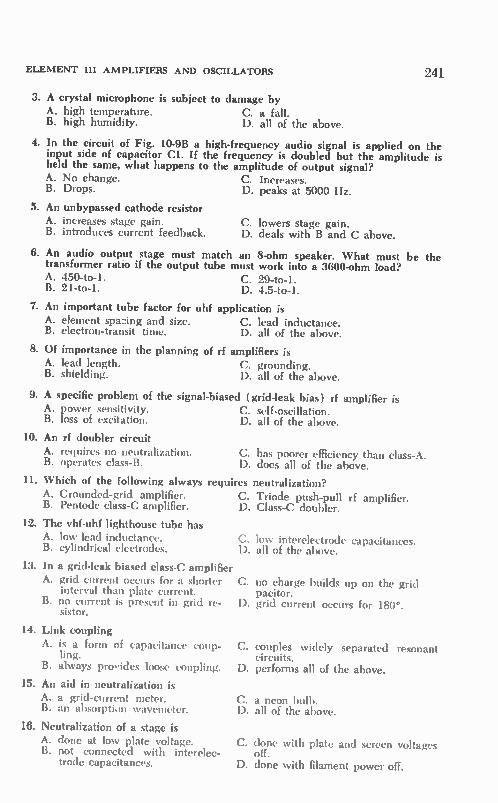
ELEMENT III AMPLIFIERS AND OSCILLATORS 241
3. A crystal microphone is subject to damage by A. high temperature. C. a fall. B. high humidity. D. all of the above.
4. In the circuit of Fig. 10-9B a high-frequency audio signal is applied on the input side of capacitor Cl. If the frequency is doubled but the amplitude is held the same, what happens to the amplitude of output signal? A. No change. C. Increases. B. Drops. D. peaks at 5000 Hz.
5. An unbypassed cathode resistor A. increases stage gain. C. lowers stage gain. B. introduces current feedback. D. deals with B and C above.
6. An audio output stage must match an 8-ohm speaker. What must be the transformer ratio if the output tube must work into a 3600-ohm load? A. 450-to-1. C. 29-to-1. B. 21-to-1. D. 4.5-to-1.
7. An important tube factor for uhf application is A. element spa2ing and size. C. lead inductance. B. electron-transit time. D. all of the above.
8. Of importance in the planning of rf amplifiers is A. lead length. C. grounding. B. shielding. D. all of the above.
9. A specific problem of the signal-biased (grid-leak bias) rf amplifier is A. power sensitivity. C. self-oscillation. B. loss of excitation. D. all of the above.
10. An rf doubler circuit A. requires no neutralization. B. operates class-B.
C. has poorer efficiency than class-A. D. does all of the above.
11. Which of the following always requires neutralization?
A. Grounded-grid amplifier. C. Triode push-pull rf amplifier. B. Pentode class-C amplifier. D. Class-C doubler.
12. The vhf-uhf lighthouse tube has A. low lead inductance. B. cylindrical electrodes.
13. In a grid-leak biased class-C amplifier A. grid current occurs for a shorter
interval than plate current. B. no current is present in grid re- D.
sistor.
C. D.
C.
14. Link coupling A. is a form of capacitance coup- C.
ling. B. always provides loose coupling. D.
15. An aid in neutralization is A. a grid-current meter. B. an absorption wavemeter.
16. Neutralization of a stage is A. done at low plate voltage. C. B. not connected with interelec-
trode capacitances. D.
low interelectrode capacitances. all of the above.
no charge builds up on the grid pacitor. grid current occurs for 180°.
couples widely separated resonant circuits. performs all of the above.
C. a neon bulb. D. all of the above.
done with plate and screen voltages off. done with filament power off.

242 SECOND-CLASS RADIOTELEPHONE LICENSE HANDBOOK
17. The function of the cathode resistor of a class-C amplifier is A. signal biasing. C. negative feedback. B. tube safety. D. neutralization.
18. A radio-frequency choke A. isolates de and rf. B. has a high rf impedance.
19. Parasitic oscillations A. occur at the fundamental fre-
quency of an amplifier. B. can be chased down with a dip
meter.
20. In a crystal oscillator circuit the frequency may be shifted slightly by A. heating the crystal. C. changing supply voltage or loading. B. placing a small capacitance in D. all of the above.
series or parallel with the crystal.
21. Purpose of a repeller plate is to A. bunch electrons. B. return electrons to cavity gap.
22. Purpose of the tsvt magnet is to A. guide electrons to repeller. B. guide electrons down helix.
C. eliminates need for neutralization. D. A and B above.
C. can result in rf output when rf ex-citation is removed.
D. B and C above.
C. attract electrons through helix. D. velocity modulate transit-time elec-
trons.
C. couple electrons to output. D. bunch electrons.
23. Feedback in a Colpitts oscillator is by way of the A. split tank capacitor. C. tickler coil. B. tapped resonant coil. D. interelectrode capacitance.
24. What happens if the rfc coil of a shunt-fed crystal oscillator opens? A. Plate voltage is removed. C. Oscillations cease. B. Frequency changes. D. A and C above.
25. What determines the frequency of a crystal? A. Size and cut. C. Supply voltage. B. Shunt capacitance of circuit. D. All of the above.

CHAPTER 11
Element Ill Amplitude-Modulation Systems
11-1. TRANSMITTERS
111-161. Discuss the following items with respect to their harmonic attenu-ation properties as possibly used in transmitter or receiver: (a) link coup-ling, (b) tuned circuits, (c) degree of coupling, (d) bias voltage, (e) de-coupling circuits, (f) shielding.—The main reason for suppressing harmonics in a transmitter is to block the radia-tion of harmonic signals that can inter-fere with other radio services. For effi-cient operation of the transmitter, many of the stages operate class-C, and there-fore the harmonic content of output signals can be quite high. These har-monics must be suppressed. In receivers, the presence of harmonic components can cause annoying heterodynes (bird-ies) and the introduction of distortion components. Harmonic components in a mixer are generated by the required nonlinearity of the mixing process, and by the strong signal components in the i-f amplifier that stem from operation on the nonlinear portion of the tube or transistor transfer characteristics (par-ticularly with the reception of a strong signal). Such harmonic components leak back into the early rf stages of the receiver where they mix with off-fre-quency signals and produce an output in the i-f frequency range. Such har-monic components in the receiver can also result in the production of inter-modulation distortion components.
(a) A link-coupled arrangement (Fig. 11-1A) minimizes the transfer of harmonic components. Such a link pre-sents a low-impedance coupling path for only that frequency to which the two resonant circuits are tuned. Very little harmonic energy is induced into the link and from the link into the sec-
ondary resonant circuit. In a link ar-rangement the two resonant circuits are usually not mutually coupled; that is, there is no direct linkage of magnetic lines between the primary and second-ary. Because of this, a link can he used to couple two widely separated resonant circuits.
(b) Of course, the greater the num-ber of resonant circuits in a chain which are tuned to the desired resonant fre-quency, the more effectively are the harmonic components rejected. This ap-plies in both the transmitter and re-ceiver amplifier chains. Two inductively coupled circuits, such as shown in Fig. 11-1B, are preferred to a single inter-stage resonant circuit in terms of har-monic rejection. However, such a coup-ling arrangement is not as effective as link coupling in the minimization of harmonics. When stages operate on the nonlinear portions of their transfer curve, the use of high-Q resonant cir-cuits helps in the reduction of harmonic levels. ( c) The degree of coupling also influ-
ences the transfer of harmonic compo-nents. In general, the looser the coupling is, the lower is the harmonic transfer. For example, in the circuit of Fig. 11-1B, the looser the coupling is between the primary and secondary resonant inductors, the better is the harmonic suppression. In terms of transmitter op-eration, this means the degree of coup-ling between stages, and between the final stage and the load, must often be opti ttt ized in terms of the most effective transfer of power and the most effective harmonic suppression.
(d) The bias voltage has an influence on the harmonic level in class-C stages. A bias should be selected in accordance with the level of the rf excitation, so
243

244 SECOND-CLASS RADIOTELEPHONE LICENSE HANDBOOK
(A) Link coupling.
(B) Mutual coupling.
(C) Shielded resonant circuits.
Fig. 11-1. Coupling arrangements.
8
that the positive peaks of the input wave do not drive the stage into plate saturation. An angle of flow should be selected which is optimum for funda-mental operation and maintains har-monic generation within reasonable levels.
Receiver rf stages operate in class-A. However, incoming strong signals may cause a swing into saturation and cut-off, and result in the formation of har-monics. In a receiver, then, a good aye-age system is helpful because signal levels can be better confined within the linear portions of the transfer charac-teristics, particularly in those stages im-mediately ahead of the detector.
(e) In a receiver, decoupling circuits are of particular advantage because they can prevent harmonic components, generated in the latter stages of the i-f amplifier, from reaching the much more sensitive rf input stages over voltage supply lines. Decoupling circuits are useful in transmitters because they also prevent the transfer of ac signal com-ponents (harmonics included) among the various stages.
Receiver selectivity is aided with the use of multiple resonant circuits. In general, loose coupling provides better selectivity than does tight coupling.
(f) Shielding is effective in minimiz-ing the direct radiation of harmonic components. Even in a receiver, the shielding of i-f and detector transform-ers minimizes the direct radiation of harmonic components back to the sensi-tive rf stages. When link coupling is used between transmitter stages, the shielding of resonant tank circuits can
FARADAY SH IELD »if
(A) Using a Faraday shield.
T. (B) Low-pass filter
ANTENNA
PI-NETWORK TANK
(C) Pi-network.
Fig. 11-2 Coupling systems that are used to reduce harmonics.
prevent direct flux-linked harmonic paths from being established between two coupled resonant circuits (Fig. 11-1C).
III-162. List several frequently used methods of attenuating harmonies in transmitters, and explain how each works.—Low-impedance coupling ar-rangements such as link coupling (Fig. 11-1) block the transfer of harmonics because of the high impedance offered by the links to any frequency other than the resonant frequency of the coupled tank circuits. The transfer of harmonic compo-
nents between two coupled resonant circuits is often largely due to capaci-tive linkage rather than flux linkage. Therefore, the use of a so-called Fara-day shield (Fig. 11-2) can minimize the transfer of harmonics by acting as a grounded capacitive shield. At the same time, the gridlike construction of the shield offers no impedance to the magnetic flux lines that link the pri-mary and secondary at the resonant frequency.
Inasmuch as harmonic radiation must be held below certain tight FCC values, the low-pass filter (Fig. 11-2B) is used extensively. A low-pass filter is usually placed in the signal-transfer path be-

ELEMENT III AMPLITUDE MODULATION SYSTEMS
tween the output of the transmitter and the antenna, and, on occasion, even between stages of the transmitter. The low-pass filter passes frequency com-ponents up to a specific limit (that limit is not too far above the funda-mental frequency which is to be trans-ferred along the signal path). As a re-sult, the filter offers high attenuation at harmonic frequencies. Sometimes additional resonant sections are added ( M-derived section added to a constant-K filter) to offer maximum rejection at the specific harmonic frequency.
Another popular circuit is the pi-network resonant circuit Fig. 11-2C). This arrangement includes an appro-priate resonant circuit of the proper Q and impedance for the transmitter stage. It also provides an impedance transfor-mation from the high-impedance output of the stage to the low impedance of an antenna system or feed system to a following stage. At the same time, it also acts as a low-pass filter and rejects the transfer of harmonic components from the resonant circuit to the load. Of course, a variety of other operat-
ing factors, such as proper shielding, correct operating bias, tank circuits of an adequate Q, etc., also aid in the minimization of harmonics. Refer to Question 111-161.
111-163. State a probable cause and methods of reducing transmitter spuri-ous emissions (otl-er than harmonics ).— Such spurious emissions can be in the form of self-excited oscillations. These result when an amplifier stage self-oscil-lates. These can he at or near to the de-sired frequency of amplification. In this case the spurious emission can be elimi-nated by the proper adjustment of an adequate neutralization system. Refer to Questions 111-133 and 111-134.
Lead inductances, stray capacitances, component parts and their arrangements can also produce parasitic oscillations at very high and very low frequencies. Proper selection of components can re-duce low-frequency parasitics, and the use of parasitic resistors and chokes can block the start of vhf parasitics. Refer to Questions 111-135 and 111-157.
Another spurious emission is sub-harmonics. In a transmitter using fre-quency multipliers, there can be a leak-through of frequency components that are submultiples of the carrier fre-quency. This can be a particular prob-lem in transistor transmitters because the fundamental-frequency output of a
245
transistor frequency multiplier is often at an objectionably high level. Properly designed multiplier resonant circuits, and sometimes special filters, are used to reduce these submultiples.
III-164. Define transmitter intermodu-lation, its possible cause (or causes), its effect, and steps that should be taken to reduce it.—Inasmuch as transmitters employ a variety of nonlinear stages, intermodulation can develop at various places in a transmitter. Mixers, fre-quency changes, inverters, modulators, and even the conventional class-C am-plifier are nonlinear circuits. As a re-sult, sum and difference components can be generated. Such spurious inter-modulation components are not only radiated, but they can result in erratic operation of a transmitter and/or the introduction of distortion components. Circuits should be used to minimize their generation, and appropriate reso-nant circuits and filters must be em-ployed to emphasize desired signal com-ponents far above the intermodulation component. Proper stage decoupling of voltage supply lines is important. Proper transmitter shielding and the use of appropriate filters in the trans-mission-line path between the trans-mitter and antenna system do much to prevent the radiation of such inter-modulation components.
Transmitter rf intermodulation is of-ten the result of the close proximity of another transmitter( s ). Such a problem exists at communications centers where there are a variety of transmitters, at broadcast-transmitter sites where a-m, fm, and tv transmitters may be in close proximity, and where a number of transmitters may have their transmitting antennas in close proximity (such as the Empire State Building with its ar-ray of tv and fm antennas for various stations). Energy components coupled back from antennas to the transmitter final amplifiers can produce intermodu-lation components and spurious emis-sions. (Class-C power amplifiers oper-ate in a nonlinear fashion.) Proper di-plexers and filters are used in order to minimize such interaction.
11-2. A-M MODULATION
III-165. Draw a block diagram of an a-m transmitter.—Refer to Fig. 11-3.
III-166. Draw a simplified circuit dia-gram of the final stages (modulator,

246
CRYSTAL OSCILLATOR
MICROPHONE
Fig. 11-3. Block diagram of an a-m transmitter.
SECOND-CLASS RADIOTELEPHONE LICENSE HANDBOOK
BUFFER AMPLIFIER
SPEECH AMPLIF IER
MULTIPLIERS AND
AMPLIFIERS
AUDIO DRIVER
modulated amplifier, push-pull linear amplifier) of a type of low-level plate-modulated transmitter utilizing a pen-tode tube in the modulated stage. Ex-plain the principles of operation. Re-peat the diagram, using a tetrode to provide high-level modulation.—Refer to Figs. 11-4 and 11-5.
In a low-level plate-modulated trans-mitter, some stage preceding the power amplifier is modulated. The rf excita-tion for the modulated pentode ampli-fier (V1) comes from a so-called rf ex-citer. The rf exciter includes the fre-quency-control oscillator and the ampli-fiers that are required to increase the rf signal to the magnitude needed at the input of the modulated amplifier. The
RF WAVE
MODULATED Co •
IIIIIIILIII AMPLIFIER
MODULATED AMPLI FIER
MODULAT,
LINEAR AMPLIFIER
ANTENNA
modulated amplifier is biased class-C, using the self-bias grid combination, Rid. Audio-modulator tubes V2 and V3 are driven by a signal from an audio amplifier. The function of the audio amplifier is to build up the microphone or other audio variations to the proper level for driving the push-pull modu-lator. Transformer Ti provides a suit-able match into the modulator. The audio variation across the secondary of output transformer T2 (usually called a modulation transformer) places an audio variation on the plate-supply voltage to the modulated amplifier.
For example, the supply voltage to the modulated amplifier may be 600 volts. The voltage variation across the
PUSH-PULL LINEAR AMPLIFIER
L2
RF MODULATION ENVELOPE
* BO
Fig. 11-4 low-level plate-modulated amplifier and linear-output amplifier.

ELEMENT III AMPLITUDE MODULATION SYSTEMS
MO DU LA TO D AMPLIF IER
VI
FROM DI RF E1IC.1._1_IlR
CT
FROM AUDIO
AMPLIFIER
CM
CD AN.N.
CT
Fig. 11-5. High-level modulator.
secondary of transformer T2 may have a peak amplitude of 600 volts. There-fore, the supply voltage for the modu-
RF INPUT WAVE
MODULATING WAVE
PLATE-CURRENT BURSTS
TANK CIRCUIT VOLTAGE
eS e es es eN
,)
es es. es es es.
V V , V , V
247
lated amplifier would vary between 0 and 1200 volts, following the audio variation at the output of the modulator. Let us consider how this influences the operation of the modulated amplifier. The supply voltage is connected to
the plate of the modulated amplifier through the radio-frequency choke (rfc). The same supply voltage is also supplied to the screen grid of the modulated amplifier through screen-grid dropping resistor R3. Thus, any variation across the secondary of the modulation transformer varies both the plate and the screen-grid voltages of the modulated amplifier.
In a class-C amplifier the plate cur-rent occurs in bursts, as shown in Fig. 11-6. The peak amplitude of these bursts of plate current depends on the screen-grid and plate voltages. When the screen-grid and plate voltages are maximum (positive peak of modulat-ing wave), the plate-current bursts also have a maximum peak amplitude. When the screen-grid and plate volt-ages dip to a low value (negative peak of modulating wave across the second-ary of the modulation transformer), the plate-current bursts are minimum in amplitude. It is apparent that the
e
u
.ess es.
es. es e 'es es
LI S./
120CN
6C0/
C/V
(A) No modulation. (B) With modulation.
Fig. 11-6. The a-m modulation process in waveforms.

248 SECOND-CLASS RADIOTELEPHONE LICENSE HANDBOOK
peak amplitudes of the plate-current bursts vary with the modulation.
It is these bursts of plate current that charge the resonant tank capacitor to its maximum negative value. The energy-storing ability (flywheel effect) of the resonant tank circuit reconstructs an rf sine wave. The peak amplitude of the plate current determines the amplitude of this rf sine wave. When there is modulation across the
secondary of the output transformer, there is a like variation in the peak amplitude of the plate current. This, in turn, determines just how far negative tank-circuit capacitor C10 is charged. Of course, the charge placed on capaci-tor CIO determines the amplitude of the sine wave that is reconstructed in the tank circuit. It follows, then, that the amplitude of the rf sine waves as they develop in the tank circuit follows the variations in the peak plate current and, in turn, the audio variations present across the secondary of the modulation transformer. Refer again to the wave-forms of Fig. 11-6. When the audio variations at the
output of the modulator are of a lower amplitude, there is a reduced peak plate-current variation. Consequently, there is a smaller variation in the peak amplitude of the rf cycles developed across the output tank circuit. In this manner, the rf variations developed across the output of the modulated am-plifier follow the changes in the modu-lating wave. The output of the modulated ampli-
fier is no longer an rf sine wave of a constant amplitude as it appears at the input of the modulated amplifier. Rather, the sine wave now varies in magnitude in accordance with the modulation. We have formed a so-called modulation envelope. If this envelope is to be increased in amplitude and power level without causing distortion, any following amplifier must operate over the linear portion of its character-istic curve. Thus, the stage that follows the modulated amplifier is not a class-C amplifier; rather, it is operated either in class-AB or class-B. It is said to be a push-pull "linear rf amplifier." To minimize distortion, the operation
of the two tubes and associated circuits should be balanced. The split-stator capacitors, C11 and C12, help to main-tain a good rf balance. The split-stator type of capacitor has two separate stator-plate sections, while a single rotor on a single axle rotates in and out of the
stator plates in a uniform manner. This rotor can then be placed at rf ground potential, as shown, to obtain a bal-anced circuit. In the linear amplifier, the modulation envelope, as it appears at the input circuit, is reproduced with fidelity in the output tank circuit.
Although not included specifically in the question, let us consider the basic function of each component part in or-der to give you a better understanding of the operation of the modulation cir-cuit and, therefore, a better understand-ing of the specific answers to many of the questions that follow.
Capacitors
Cl. This capacitor has a low react-ance at the rf frequency, and it serves as a means of coupling the rf output of the exciter to the input of the modu-lated amplifier. It is also the capacitive portion of the combination, RIC1.
C2. An rf bypass capacitor that keeps radio-frequency energy out of de meter Ml.
C3. An rf filter capacitor that pre-vents rf degeneration.
C4. This is an rf filter capacitor that grounds the screen-grid in terms of the rf signal. However, its reactance is high enough at audio frequencies so as not to interfere with the variation of the modulated screen-grid voltage.
C5. This is a plate rf filter capacitor with a function similar to that of C4. It presents a short circuit to the rf signal, but at the same time it does not prevent the modulating wave from varying the plate supply voltage.
C6. A de blocking capacitor that keeps the de plate voltage from the tank circuit and prevents coil Li from shorting out the de plate voltage.
C7. This capacitor has a low react-ance in the audio frequency range, and it acts as a bias-source filter.
C8. This capacitor acts as a plate supply-voltage filter, keeping audio vari-ations out of the power supply.
C9. This capacitor has a similar func-tion to C8, but in terms of the screen-grid voltage.
C10. Resonant-circuit capacitor. C11. Split-stator capacitor of the grid
resonant circuit. C12. Split-stator capacitor of the
plate resonant circuit. C13, C14. Screen-grid filter. C15. Plate-voltage filter. C16. Rf bypass around de meter. C17. Bias-supply filter capacitor.

ELEMENT III AMPLITUDE MODULATION SYSTEMS
Resistors RI. Grid-bias resistor and part of
RIC1 time constant. R2. Safety cathode resistor that pro-
tects the tube with a loss of rf. R3. Screen voltage dropping resistor.
Inductors
Rfc. Radio-frequency chokes that keep radio-frequency energy out of the supply-voltage lines and permit the connection of dc voltages without shunting the radio-frequency signals.
Li. Plate tank coil of the modulated amplifier.
L2. Grid tank coil of the linear am-plifier.
L3, L4. Parasitic chokes. L5. Coil of the linear-amplifier plate
resonant circuit. Ti. Audio-input transformer. T2. Modulation transformer.
Motors
MI. De grid-current meter. M2. Dc plate-cu-rent meter for the
modulator. For class-AB and class-B operation the indication of this meter will vary with the audio modulation. M3. De plate current meter for the
modulated amplifier. With a properly designed and tuned a-in modulation system, this meter will not change with modulation. M4. De grid-current meter for the
linear amplifier. M5. De cathode-current meter for
the linear amplifier. This current read-ing approximates the total plate cur-rent drawn by the two linear-amplifier tubes. The circuit of Fig. 11-4 is that of a
"low-level modulation system." It is called low-level modulation because the modulation occurs ahead of the final rf power amplifier which, in this case, is in the form of a push-pull linear amplifier. The circuit of Fig. 11-5 is called a
"high-level modulation system" because the final radio-frequency amplifier (the one feeding the antenna) is plate modulated. The modulated amplifier is identical to that of Fig. 11-4, except that a tetrode tube instead of a pentode tube is being used, and the plate reso-nant-tank circuit is a pi-network in-stead of a simple parallel LC combina-tion. The combination of C6, C7, and Li is a parallel circuit, that is resonant at the output rf frequency. However, the split-capacitor arrangement also
249
functions as an impedance transformer. Looking into the pi-network from the tube, a high impedance is seen, match-ing the high-impedance output of the modulated amplifier. Looking into the network from the antenna side, one sees a low impedance, and a match is pro-vided to a low-impedance antenna sys-tem. In this high-to-low impedance transformation, capacitor C7 is several times larger than capacitor C6. The pi-network arrangement is also funda-mentally a low-pass filter. When the values are chosen properly, this type of tank circuit has a maximum rejection of harmonic and other higher-frequency components and minimizes their trans-fer to the antenna system. The modulator is a push-pull type,
similar to that of Fig. 11-4. The modu-lation process occurs in exactly the same manner, with the modulating wave varying the screen-grid and plate-supply voltages to the modulating amplifier. In this manner, the rf peak plate-current bursts of the modulated amplifier also vary in amplitude, and a modulation envelope (amplitude modulated) is de-veloped in the pi-network tank circuit.
III-167. Draw a simple schematic dia-gram showing a method of coupling the modulator tube to a radio-frequency power-amplifier tube to produce grid modulation of the amplified rf energy. Compare some advantages or disad-vantages of grid modulation with those of plate modulation.—Refer to Fig. 11-7. In the example, the final rf power am-plifier is grid-modulated instead of plate-modulated. Note the manner in which the circuit arrangements of Figs. 11-7 and 11-5 differ. The screen-grid and plate-output circuits are identical, with the exception that the screen-grid and plate voltages are not modulated. Rather, the modulation transformer is located in the grid circuit of the modulated am-plifier. The modulator can be either a single-
ended or a push-pull amplifier. Inas-much as the amount of audio power re-quired to grid-modulate an amplifier is much less than that required to plate-modulate the same amplifier, a single-ended audio amplifier-modulator is often employed. Such a single-ended modu-lator stage is shown in Fig. 11-7. The turns ratio of the modulation trans-former is such that a match is made be-tween the output of the class-A audio power amplifier and the input imped-
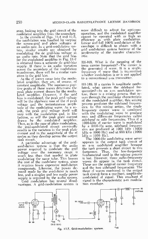
250 SECOND-CLASS RADIOTELEPHONE LICENSE HANDBOOK
ance, looking into the grid circuit of the modulated amplifier from the secondary.
In the circuits of Figs. 11-4 and 11-5, the modulation was handled by varying the screen-grid and plate voltages at an audio rate. In a grid-modulation sys-tem, similar results are obtained by modulating the de grid-bias voltage at an audio rate. Note that the grid bias for the modulated amplifier in Fig. 11-7 is obtained from a separate de grid-bias supply. If there is an audio variation across the secondary of the modulation transformer, there will be a similar vari-ation in the grid bias.
As the rf waves come into the modu-lated amplifier, they are, of course, of constant amplitude. The maximum posi-tive peaks of these waves determine the peak plate current drawn by the modu-lated amplifier. However, if the grid bias is modulated, the peak grid voltage will be the algebraic sum of the rf peak voltage and the instantaneous ampli-tude of the modulating wave. As a re-sult, the peak grid voltage itself will vary with the modulation and, in like fashion, so will the peak plate current drawn by the modulated amplifier. Thus, as in the case of plate modulation, the grid-modulated circuit eventually results in the variation in the peak plate current and in the magnitude of the rf cycles as they develop across the output tank circuit. A particular advantage of the grid-
modulation system is that the audio power required to modulate the grid voltage over the necessary range is much less than that needed in plate modulating the same tube. This lowers the cost of the modulator system, since it requires fewer expensive modulation components. Likewise, the power de-mand made by the modulator is much less, and a simpler and less costly power supply is required by the audio system.
Grid modulation has several 'disad-vantages. A grid-modulation system is
INPUT AUDIO
GRID BIAS
more difficult to adjust for optimum operation, and the modulated amplifier cannot be operated with as high an efficiency as with plate modulation. Linear and full 100% modulation of the envelope is difficult to obtain with a grid modulation system because of the nonlinearity of the transfer character-istic.
111-168. What is the meaning of the term carrier frequency?—The carrier is the generated rf wave. It is a single-frequency rf wave that is transmitted whether modulation is or is not applied to a conventional a-m transmitter.
111-169. If a carrier is amplitude modu-lated, what causes the sideband fre-quencies?—In an a-m modulation sys-tem, there is a mixing process that oc-curs through the nonlinear characteristic of the modulated amplifier; this mixing process produces the sideband frequen-cies. In this mixing action, the single frequency carrier wave is combined with the modulating wave to produce sum and difference frequencies called sideband or side frequencies. Thus if a 1000-kHz rf carrier wave is modulated by a 1000-Hz note, sideband frequen-cies are produced at 1001 kHz (1000 kHz -1- 1000 Hz) and at 999 kHz ( 1000 kHz — 1000 Hz). The 1000-Hz modulating wave never
appears in the output tank circuit of an a-m modulated amplifier because the tank presents a short circuit to this frequency. Thus, the low-frequency fundamental used in the mixing process is lost. However, three radio-frequency waves do appear in the tank circuit. These are the original carrier frequency and the two sideband frequencies. The three rf waves combined in the output tank circuit form a resultant, amplitude-modulated rf signal. This resultant rf signal is the characteristic a-m modula-tion envelope.
Fig. 11-7. Grid-modulation system.
TO AS
T T

ELEMENT III AMPLITUDE MODULATION SYSTEMS
III-170. What determines the band-width of emission for an a-m transmis-sion?—It is determined by the highest frequency in the modulating wave. In the preceding example there were two side frequencies, appearing 1000 Hz to each side of the carrier frequency. Thus, the total signal occupies a bandwidth of 2000 Hz (± 100C Hz). Perhaps the highest frequency transmitted by the station is 5000 Hz. Now the total band-width of emission that would be re-quired is 10,000 Hz ( -± 5000 Hz) be-cause the side frequencies extend as far as 5000 Hz on each side of the carrier frequency.
III-171. What is the relationship be-tween the percent of modulation and the shape of the waveform envelope, relative to carrier amplitude?—The higher the modulation percentage is, the greater is the magnitude of the crest-to-trough variation of the modu-lation envelope, relative to the ampli-tude of the unmodulated carrier. Stated as a simple equation this is:
Em•,, — Ems. % modulation _ x 100
zn, • rrl er
Refer to Fig. 11-8. When the modula-tion envelope is 100% modulated, the crest of the envelope rises to twice the peak amplitude of the unmodulatcd car-rier, and in the trough the modulation envelope falls away to zero during the negative crest of the modulating wave.
III-172. Why does exceeding 100% modulation in an a-m transmission cause excessive bandwidth of emission? —When the modulation exceeds 100%, side frequencies, in addition to the single sideband pair normal to the a-m modulation process, are produced. The side-frequency components are farther displaced from the carrier than the nor-mal sideband pair. As a result, the
E MAX E fix Em IN
UNMODULATED CARRIER
100% MODULAT ION
501. MODULATION
Fig -8 Moaulation percentages.
251
transmitter signal spreads out and oc-cupies a much wider band of frequen-cies. In fact, the side frequencies can be so far removed from the carrier that they appear in the channels assigned to another station, causing interference. The splatter takes place because the
actual modulating sine wave is distorted when 100% modulation is exceeded. Such distortion introduces harmonic-signal components that are not normally present in the modulating wave, and thus a wider band of signal components is transmitted.
111-173. What is the relationship be-tween the average power output of the modulator and the plate circuit input of the modulated amplifier, under 100% sinusoidal modulation? How does this differ when normal-voice modulation is employed?—To attain 100% modula-tion it is necessary that the average power output of the modulator be one-half of the de power input to the plate-modulated amplifier. However, because of the high-peaked and irregular varia-tions of speech waveform, the average power output needed to sustain 100% modulation on voice peaks is much less than that required for 100% sinusoidal modulation. It can be estimated that the average audio-power output in terms of voice transmission need only be about one-quarter of the de power input to the de plate-modulated amplifier.
III-174. What is the relationship be-tween the amount of power in the side-bands and the intelligibility of the sig-nal at the receiver?—The greater the power in the sidebands is, the higher is the amplitude of the recovered signal at the receiver. Thus, the higher the average sideband power is, the louder is the signal at the receiver. Greater in-telligibility results in the presence of noise and interference, assuming there is no distortion caused by overmodula-tion, severe clipping, etc.
IH-175. How does a linear power am-plifier differ from other types?—It dif-fers in that it is biased to operate in a linear manner in terms of the amplitude variations of an applied radio-frequency modulation envelope. Thus, the a-m envelope can be applied to its input, and an amplified replica will be de-veloped across its output. If such a wave were applied to the input of a conventional class-C amplifier, the out-put would be distorted.

959 SECOND-CLASS RADIOTELEPHONE LICENSE HANDBOOK
IH-176. What would cause a dip in the antenna current when a-m is applied? What are the causes of carrier shift?— Such a dip may be the result of the inability of the modulator or modu-lated amplifier to follow the modulation crest. Improper operating conditions in the grid circuit, such as incorrect bias or insufficient rf excitation, could pre-vent generation of the high peak power necessary to convey the modulation crest. A defective modulated amplifier, a power-supply component failure, or poor regulation can also kick the an-tenna current down. Too heavy load-ing of the modulated-amplifier output by the antenna system can cause the same disturbance.
Carrier shift in an a-m modulated transmitter refers to a fluctuation in the de plate current with modulation. Some of the causes of negative carrier shift (plate current dip with modulation) are a distorted modulating signal, im-proper impedance match between modulator and modulated stage or be-tween modulated stage and its load, a failing modulated amplifier tube, poor power-supply regulation, and insuffi-cient radio-frequency excitation at the grid of the modulated amplifier. An upward kick of the plate meter (posi-tive carrier shift) can be caused by improper neutralization or overmodula-tion.
III-177. What is meant by frequency shift or dynamic instability, with refer-ence to a modulated rf emission?—This refers to any change in the carrier fre-quency with modulation.
III-178. What might cause frequency modulation in an a-m radiotelephone transmitter?—The two most likely causes are changes in loading of the oscillator with modulation and changes in the oscillator supply voltage with modulation. The frequency of an oscil-lator, even though it might be crystal controlled, is influenced to some extent by its electrode supply voltages and by the load applied to its output. Thus if the oscillator supply voltage changes as a result of the changing power demand of the modulator or modulated ampli-fier, there can be an actual shift in frequency of the oscillator with modu-lation, thus producing frequency modu-lation of the carrier. Likewise, if a changing load is reflected to the output circuit of the oscillator from a following
modulated amplifier, a similar fm modu-lation of the a-m frequency can result.
11-3. SINGLE SIDEBAND
111-179. Draw a block diagram of an sssc transmitter (filter type) with a 20-kilohertz oscillator and an emission frequency in the range of 6 MHz. Ex-plain the function of each stage.—Such a block diagram is shown in Fig. 11-9. Single sideband or single-sideband sup-pressed-carrier (sssc) transmission sys-tems use an a-in modulation process. However, in the modulator and/or fol-lowing phasing or filtering system, both the carrier and one sideband are re-moved. Only a single sideband is trans-mitted. The process starts with a carrier oscil-
lator; in the example, this oscillator op-erates at 20 kHz. Its output is applied to a balanced modulator, along with the audio signal. Let us assume that the audio bandwidth extends no higher than 3 kHz. The function of the bal-anced modulator is to amplitude modu-late an rf wave at the same time that the carrier frequency itself is removed. The output of the modulator then con-sists of two sideband spectrums, one on each side of the carrier frequency. Both sidebands are present, but the carrier has been removed. The next step is to remove one side-
band. This is done with a so-called side-band filter. It offers maximum rejection to the carrier frequency and one of the sidebands. However, the other sideband frequency spect is passed to a follow-up mixer. In this manner, the single-sideband signal has been formed. In the example this signal contains those side frequencies present between 20.3 and 23 kilohertz. The low-frequency sideband and the carrier are no longer present. The next step is to convert the side-
band signal to the transmit frequency and provide the necessary power ampli-fication. The frequency step-up occurs in one or several mixers. Finally, there is a channel oscillator or transmit fre-quency generator which sets the trans-mit carrier frequency. In the mixer, this component is combined with the single sideband signal. In the mixing process the sideband frequencies are raised to the 6-MHz level, with the sum fre-quency appearing in the output. The mixer, too, is a balanced arrangement, so that the carrier frequency is removed. No 6-MHz component is transmitted.

ELEMENT III AMPLITUDE MODULATION SYSTEMS
20.3 - 23kHz
LOW FREQUENCY OSCILLATOR
20k Hz
SPEECH AMPLIF IER
RF AMPLIFIER
BALANCED MODULATOR
300-3030 Hz
AUDIO OUTPUT
SIDEBAND FILTER
MIXING OSCILLATOR I 8MHz
1.8203-1.823MHz
FIRS' MIXER
LOCAL OSCILLATOR 4.18MHz
I.8203-1.823MHz
MIXER
I. 8M Hz
FREQUENCY GENERATOR 4 I8A1Hz
4. 18A1Hz (A) Transmitter.
SECOND MIXER
1 EIMHz
SECOND OSCILLATOR
I.8MHz
Fig
AUDIO AMPLIFIER
1 SPEAKER
03) Receiver.
20.3-23kHz
SIDEBAND FILTER
LINEAR RF 1_.... ANTENNA AMPLIFIERS
MIXER
1 F AMPLIFIER
PRODUCT DETECTOR
3W-3000Hz
11-9 The functional plan of an sssc system.
The single sideband frequency is then increased in level with one or more linear amplifiers to the final transmitting power. Linear amplifiers are used so as not to distort the singie-sideband modu-lation envelope applied to the input. Conventional class-C amplifiers cannot be used.
HI-180. Explain the principles involved in a single-sideband suppressed-carrier (sssc) emission. How does the band-width of emission and required power compare with that of full carrier and sidebands?—A single sideband is formed using an amplitude-modulation process. However, in the actual modulation process the carrier is removed. Further-more, follow-up circuits also remove one of the sidebands, and only a single sideband remains for transmission. The required bandwidth is therefore slightly less than one-half of that needed to transmit the conventbnal full carrier and two sidebands. A single-sideband system conserves
a considerable amount of power. With 100% modulation, a standard a-m modulated transmitter, with a rated carrier power of 100C watts, radiates 250 watts per sideband. The carrier
?0 3 - 23kHz
CARRIER OSCILLATOR
20k Hz
253
TO
6.11003- 6.003 MHz
power is 1000 watts and the total side-band power is 500 watts. Hence, the average transmitter-power rating is 1500 watts. To generate a 250-watt single-sideband signal, the power of the transmitter would only have to be 250 watts, instead of the much higher power requirements of a transmitter which transmits full carrier and side-bands with each sideband having a power level of 250 watts.
Comparisons are often made in terms of signal-to-noise ratio at the receiver. It can be proved that a single-sideband transmitter rated at 500 watts delivers a signal of the same ratio as a standard a-m transmitter with a 1000-watt car-rier output ( 1500-watt total rating).
IH-181. Explain briefly how an sssc emission is detected.—The single-side-band receiver is usually a superhetero-dyne type. Quite often double conver-sion is used, and the low-frequency i-f amplifier also includes a sideband filter. The filter has a narrow response and passes only the desired sideband to the detector. Furthermore, it offers maxi-mum rejection of the carrier frequency and the unwanted sideband. There-fore, any interference components in

254 SECOND-CLASS RADIOTELEPHONE LICENSE HANDBOOK
this frequency range are prevented from reaching the detector. The single-sideband receiver must
have a stable detection system. A so-called product detector is most often used. It is again a mixing process which recovers the original audio variation. The oscillator associated with the prod-uct detector (Fig. 11-9) generates a very stable carrier-frequency compo-nent. In the example it is a 20-kHz oscil-lator. In the product detector, this 20-kHz component mixes with the incom-ing sideband signal. The output cir-cuit of the product detector is tuned to the difference frequency. In this case, the difference frequency is the original audio variation. Thus, the original audio is recovered (detected) using a mix-ing process.
11 -4 RECEIVERS
III-182. Draw a block diagram of a single conversion a-m superheterodyne receiver. Assume an incoming signal, and explain briefly what occurs in each stage.—Refer to Fig. 11-10. The in-coming signal picked up by the antenna system is first increased in level by a radio-frequency amplifier. (Those re-ceivers that do not use a radio-fre-quency amplifier apply the incoming signal directly to the mixer.) The func-tion of the mixer is to beat the incom-ing signal down to the i-f frequency range. A local oscillator generates the beating signal used in this process. In the example the local oscillator operates on a frequency higher than that of the incoming signal. For a 1000-kHz incom-ing signal, the local oscillator signal must be at 1455 kHz to produce an i-f
SIGNAL GENERATOR CONNECTION POINTS
LOCAL OSCILLATOR
1_
frequency output of 455 kHz. In the mixing arrangement the difference fre-quency is emphasized in the output, while the sum and two fundamental frequencies are rejected. In receiving a signal on a different frequency, say 1200 kHz, the local oscillator operates on 1655 kHz. Again a difference fre-quency signal of 455 kHz appears at the mixer output. The i-f amplifier is fixed-tuned to 455
kHz, and it builds up the magnitude of the i-f signal taken off at the output of the mixer. Finally, the signal is in-creased to a level which permits linear operation of an a-m detector. Usually this a-m detector is a diode, rectifying either the positive or the negative alter-nation of the incoming modulation en-velope. A pulsating, unidirectional di-ode current results. The detector also includes an output-filter arrangement. This part of the detector smooths out the pulsations and forms a replica of the original audio variation. The recovered audio signal is now increased in ampli-tude to the level necessary for driving a speaker. This is the task of the audio amplifier.
III-183. Explain the relation between the signal frequency, the oscillator fre-quency, and the image frequency in a superheterodyne receiver.—The signal frequency is that of the desired incom-ing signal. It is mixed with the local-oscillator frequency to produce an i-f frequency component. An image fre-quency is an undesired signal frequency that is positioned on the other fre-quency side of the local-oscillator fre-quency. In the example in Question HI-182 and Fig. 11-10 it would be the
AVC DETECTOR AND FILTER
CONNECT VTVPA
Fig 11 -10 Block diagram of an
SCOPE CONNECTION
POINTS
/ 4 SOUND
a-m receiver, showing .it points.
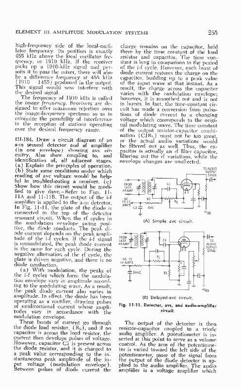
ELEMENT III AMPLITUDE MODULATION SYSTEMS
high-frequency side of the local-oscil-lator frequency. Its position is exactly 455 kHz above the local oscillator fre-quency, or 1910 kHz. If the receiver picks up a 1910-kHz signal and per-mits it to pass the mixer, there will also be a difference frequency at 455 kHz (1910 — 1455) produced in the output. This signal would now interfere with the desired signal. The frequency of 1910 kHz is called
the image frequency. Receivers are de-signed to offer maximum rejection over the image-frequency spectrum so as to minimize the possibility of interference in the reception of stations operating over the desired frequency range.
III-184. Draw a circuit diagram of an a-m second detector and af amplifier (in one envelope) showing aye cir-cuitry. Also show coupling to, and identification of, all adjacent stages. (a) Explain the principles of operation. (b) State some conditions under which reading of avc voltage would be help-ful in troubleshooting a receiver. (c) Show how this circuit would be modi-fied to give davc.—Refer to Figs. 11-11A and 11-11B. The output of the i-f amplifier is applied to the a-m detector. In Fig. 11-11, the plate of the diode is connected to the top of the detector resonant circuit. When the rf cycles in the modulation ervelope swing posi-tive, the diode conducts. The peak di-ode current depends on the peak ampli-tude of the i-f cycles. If the i-f signal is unmodulated, the peak diode current is the same for each cycle. During the negative alternation of the rf cycle, the plate is driven negative, and there is no diode conduction.
(a) With modulation, the peaks of the i-f cycles which form the modula-tion envelope vary ;n amplitude accord-ing to the modulating wave. As a result, the peak diode cu-rent also varies in amplitude. In effect. the diode has been operating as a rectifier, drawing pulses of unidirectional ctrrent whose ampli-tudes vary in accordance with the modulation envelope. These bursts of current go through
the diode load resistor, (Ri.), and, if no capacitor is across the load resistor, the current then develops pulses of voltage. However, capacitor Cl is present across the diode resistor, and it is charged to a peak value corresponding to the in: stantaneous peak amplitude of the in-put voltage (mociulation envelope). Between pulses of diode current the
255
charge remains on the capacitor, held there by the time constant of the load resistor and capacitor. The time con-stant is long in comparison to the period of the i-f cycle. However, each burst of diode current restores the charge on the capacitor, building up to a peak value of the input wave at that instant. As a result, the charge across the capacitor varies with the modulation envelope; however, it is smoothed out and is not in bursts. In fact, the time-constant cir-cuit has made a conversion from pulsa-tions of diode current to a changing voltage which corresponds to the origi-nal modulating wave. The time constant of the output resistor-capacitor combi-nation (C1111.) must not be too great, or the actual audio variations would be filtered out as well. Thus, the ca-pacitor is actually an rf filter capacitor, filtering out the rf variations, while the envelope changes are unaffected.
TO AUDIO OUTPUT STAGE
FROM LAST
IF AMP
-DC TO I-F AMPS
(A) Simple avc circuit.
FROM LAST I-F AMP
-DC TO I-F AMPS
T DAVC R3
TO AUDIO OUTPUT STAGE
* BB
(B) Delayed-avc circuit.
Fig. 11-11. Detector, avc, and audio-amplifier circuit.
The output of the detector is then resistor-capacitor coupled to a triode audio amplifier. A potentiometer is in-serted at this point to serve as a volume control. As the arm of the potentiome-ter is varied toward the left side of the potentiometer, more of the signal from the output of the diode detector is ap-plied to the audio amplifier. The audio amplifier is a voltage amplifier which

256 SECOND-CLASS RADIOTELEPHONE LICENSE HANDBOOK
increases the magnitude of the rela-tively weak detected signal to a proper level for driving the audio power-output stage. This stage supplies the necessary power for driving the speaker. Coming off the diode load is still an-
other signal path, through a very high value of resistor (R2) and a follow-up large-value capacitor (C2). The time constant of this combination is very long, and it is capable of filtering even the audio variations at the output of the diode detector. Thus the R2C2 combi-nation is both an rf and an audio filter, and no rf or audio variations appear across avc filter capacitor C2. Instead, a de voltage which corresponds to the average level of the received signal is present across the capacitor. With no incoming signal there would be no di-ode current, and, therefore, no charge would be placed on the aye capacitor. The charge on the ave capacitor is a function of signal strength. The stronger the incoming signal is, the higher is the negative voltage developed across the capacitor. A problem introduced by a strong in-
coming signal is that it drives one or several of the rf/i-f stages of the re-ceiver into the distorted high-bias or saturated regions. However, if the nega-tive de voltage developed across the aye filter capacitor is fed back as an addi-tional bias to certain earlier stages, it is able to reduce the gain of the stage. Therefore, a strong incoming signal is not amplified as much and is not per-mitted to swing into the distorted re-gions. By so doing, a receiver can be made much more sensitive to weak in-coming signals because the hazard of distortion on strong incoming signals has been reduced. When a weaker signal is being re-
ceived, less negative voltage appears across the ave circuit, and the amplifier gain is not reduced as much, permitting the weaker incoming signal to be am-plified a greater amount than a stronger incoming signal. The net re-sult is to maintain the strength of the detected output signal more uniform than if no aye were employed.
(h) The aye voltage is a dc voltage which corresponds to the strength of an incoming signal. Inasmuch as it varies with signal level, it is a very useful alignment indicator. As the various stages of a receiver are peaked for best performance, it will be so indicated by a peak voltage reading on the aye line, as measured on a dc vtvm. When no
signal is reaching the detector, there is of course no aye voltage. A signal generator can be moved
back through the i-f and if amplifiers of the receiver to find a spot at which the signal has dropped out. This will be indicated by no reading, or a very sharp drop in the reading of a vtvní placed across the ave line. As the signal gen-erator is moved from stage to stage from the detector back toward the an-tenna-output stage, there will be addi-tional amplification, with less input sig-nal needed to produce the same read-ings on the ave line.
(c) For the very best reception of a very weak signal, it is best that no ave voltage be applied. This can be accom-plished by using a delayed automatic volume control (davc) system. In this arrangement the ave circuit does not function until the incoming signal has exceeded a certain level. Thus the am-plifier is able to operate wide open with the reception of a weak signal. At the same time a strong signal will put the ave into operation and reduce the am-plifier gain.
Delayed aye can be accomplished with the use of a second diode in the detector. This diode is connected so that a negative de voltage appears between the diode plate and cathode. In Fig. 11-11B this negative voltage is a result of the de cathode- bias voltage devel-oped across the cathode resistor for the audio-amplifier section of the tube. Thus an incoming rf signal, arriving via capacitor C3, cannot cause the ave di-ode to conduct until it first overcomes the reverse diode dc bias. If the signal is strong enough to do so, diode current will go through resistor R3, and a negative de voltage corresponding to the average strength of the incoming strong signal will appear on the aye line.
It is to be noted that the operation of the detector diode itself is not de-layed, because diode load resistor Ri. is connected directly to the cathode rather than to ground.
III-185. Draw a bfo circuit diagram, and explain its use in detection.—A beat-frequency oscillator ( bfo ) circuit is shown in Fig. 11-12. It is an electron-coupled oscillator (Hartley oscillating section) that operates at the i-f fre-quency. Such a circuit is used in the reception of cw (code) signals. In con-tinuous-wave code transmission, the ac-tual rf carrier at the transmitter is in-

ELEMENT III AMPLITUDE MODULATION SYSTEMS
TO I-F INPUT OF A M •+-1 DETECTOR
RFC
LW TUNE ADJUST
+EBB
Fig. 11-12. Bfo circuit.
terrupted and turned on by the spaces and marks (dots and dashes) of the code message. A dot turns on the car-rier for a short interval of time; a dash turns on the carrier for a longer inter-val. During the spacings between marks, the carrier is turned off. The bfo at the receiver converts the incoming in-terrupted cw signal to an interrupted audible tone.
In operation the output of the beat-frequency oscillator (bfo) is applied to the same a-m detector as the incom-ing interrupted i-f carrier code signal. The frequency of the bfo signal is very near to the frequency of the in-coming i-f carrier—so near, in fact, that the difference between the two frequen-cies is an audible tone (400 Hz, 1000 Hz, or whatever the adjusted frequency difference between the two signals is). During the space between marks, there is no incoming i-f carrier and no signal against which the bfo signal can beat. Therefore, during spaces, there is no output from the detector. During the dots and dashes, however, there is both an incoming carrier and a bfo com-ponent which beat together. The differ-ence frequency is developed in the out-put and is amplified and reproduced as an audible tone by the headset or speaker. Thus the dot and the dash marks can be heard, and the message can be translated from the code to cor-responding letters and words. The vari-able capacitor adjusts the cw tone.
III-186. What would be the advan-tages and disadvantages of utilizing a bandpass switch on a receiver?—A bandpass switch can be used to set the receiver bandwidth in accordance with the emission bandwidth of an incom-ing signal. A code signal has a rather
257
narrow bandwidth, and therefore a bandpass switch can be set for mini-mum bandwidth. In so doing, the sig-nal-to-noise and signal-to-interference ratios are reduced because of the much narrower range of frequencies that will be received.
However, if the bandwidth is made too narrow, a modulated signal which occupies an appreciable bandwidth will not be fully detected, and distortion results. A narrow bandwidth is a prob-lem when the receiver is subject to drift; it may be necessary to frequently retune the receiver to be sure that the signal to be received comes through on the narrow bandpass established by the bandpass switch. The bandpass switch is an additional receiver adjustment, and it must be set in accordance with the emission bandwidth to be received. Some additional component parts and receiver complexity are involved, and therefore there is an additional cost factor.
III-187. Explain what is meant by the sensitivity of a receiver; selectivity of a receiver. Why are these important? In what units are they usually ex-pressed?—Sensitivity has to do with the ability of a receiver to produce an in-telligible output from an incoming weak signal. Thus, sensitivity is important in terms of the capability of a receiver to handle very weak incoming signals. The ultimate sensitivity of a receiver is influ-enced by noise. Exceptional gains are possible, and very weak signals can be amplified tremendously. However, a useful output can be obtained only when the signal can be made to domi-nate the noise. The selectivity of a receiver has to
do with the ability of a receiver to cope with interfering signals that are present on nearby frequencies. The narrower the bandwidth of a receiver is, the greater is its selectivity, and the more free it is from interference from signal components on nearby frequencies. However, receiver bandwidth must he adequate to pass the emission band of the incoming signal. Thus, for good selectivity, the response of the receiver should be very sensitive to the required emission bandwidth and then drop off very sharply on each side of the de-sired bandpass. When the receiver bandpass is
narrow, not only is the selectivity im-proved, but there can also be an im-provement in sensitivity. The noise in-

258 SECOND-CLASS RADIOTELEPHONE LICENSE HANDBOOK
herent in the receiver is a function of the receiver bandwidth. Thus, the noise content too is reduced, and there is a direct relationship between selectivity and the ultimate sensitivity for a given receiver design.
Receiver sensitivity is usually ex-pressed in microvolts. If a receiver has a sensitivity of 2 microvolts, it means that this level of input signal will pro-duce a usable, standard test output. For high-frequency operation where noise generated within the receiver is of significance, such noise becomes a limitation on the ultimate sensitivity. At lower frequencies, external noises are usually the limiting factor in just how weak a signal can be recovered.
Selectivity is usually stated in fre-quency bandwidth. Usually this band-width is the frequency difference be-tween the high-frequency point at which the response is 6 dB down from maximum and the low-frequency point at which the response is also 6 dB down.
111-188. Explain, step by step, how to align an a-m receiver, using the follow-ing instruments: signal generator and speaker; signal generator and oscillo-scope; signal generator and vtvm. Also explain briefly what is occurring during each step.—A block diagram for illus-trating alignment is shown in Fig. 11-10. The speaker, oscilloscope, and vtvm are all forms of output indicators that are useful in the alignment of a receiver. The speaker is an aural indicator; one makes the alignment by listening to the tone emitted by the speaker. When this type of indicator is used, the signal applied from the signal generator must be modulated (usually by a 400-Hz tone) so that the output of the speaker can be heard. When an oscilloscope is used as an alignment indicator, it is often attached across the voice coil of the speaker, although it can be con-nected at various other points in the receiver between the speaker and the output of the detector. The oscilloscope provides a visual display of the 400-Hz tone which is being used to modulate the signal-generator output. The ‘tvm is also a visual type of
indicator, and it is connected across the ave line. When a vtvm is used as an alignment indicator, the signal-gener-ator output need not be modulated. Re-call that the aye line carries a dc voltage which corresponds to the average level of the applied rf signal. Many published
alignment procedures for commercial models are 'based on the use of a vtvm as an alignment indicator. Often specific levels of aye voltage for suggested val-ues of signal-generator input voltage are given in the alignment information. The alignment procedure progresses
from the diode detector toward the an-tenna input of the receiver. Usually the detector transformer is peaked first by applying an i-f frequency from the sig-nal generator to the input of the last i-f stage (or the only i-f stage in some small a-m receivers). The secondary and then the primary resonant circuit is tuned for a maximum output. Such a maximum output is indicated by the loudest tone heard via the speaker, a maximum deflection of the modulating waveform on the oscilloscope screen, and a maximum reading of the de volt-age on the aye line by the vtvm. In many alignment procedures a suggested level of input signal is given, and/or the signal level is adjusted for a specific reading on the aye line. Inasmuch as alignment controls often interact, it may be necessary to jockey back and forth between secondary tuning and primary tuning in locating the optimum settings. The signal generator is now moved
to the grid of the next i-f stage in the direction of the antenna input, or if only a single i-f stage is employed, to the grid circuit of the mixer. Inasmuch as an additional stage of amplification is now added, it is necessary to reduce the output of the signal generator. It is important not to overload the receiver in performing the alignment, and in most cases it is advisable that alignment be made with a relatively weak input signal. The input signal should be com-parable to the signal values that will he present in the reception of broadcast stations with medium-to-weak signal strengths.
If the receiver has more than one i-f stage, the signal generator is now moved to the input of the mixer, and the i-f transformer between the mixer and the input of the first i-f amplifier is peaked. In the preceding steps we have applied a signal that corresponds to the i-f fre-quency of the receiver. The individual i-f transformers and their associated resonant circuits have been aligned for resonance, as indicated by maximum readings on the indicator. The next general procedure for the
alignment of the receiver is to tune the mixer-input circuit, local-oscillator res-onant circuit, and, if included, the res-

ELEMENT lU AMPLITUDE MODULATION SYSTEMS
onant circuits of an rf amplifier. In this alignment procedure the signal gener-ator is usually connected to the antenna input. Depending on the recommended alignment procedure. its output should be set to a specific level, or it should be adjusted until there is a particular volt-age reading as measured on the avc line. The next step is to align the antenna
input and rf circuits. Usually this is done at the high-frequency end of the received band. If the antenna is sup-plied directly to the mixer, it is only necessary to peak the antenna-input resonant circuit. If the receiver uses an rf amplifier, both the antenna input and the resonant circuit between the output of the rf amplifier and the input of the mixer must be peaked.
Most often the mixer-oscillator is aligned with the use of a signal set to some frequency at the high-frequency end of the band. In fact, if at all pos-sible, the generator should be set pre-cisely to some particular frequency. When this frequency is tuned in on the receiver, the reading on the receiver dial should match the frequency to which the signal generator has been set. If this is not so, the dial of the receiver should be set to the exact frequency of the generator. Then the trimmer capaci-tor which is in the local-oscillator cir-cuit should be adjusted until the mcom-
259
ing generator signal peaks at this setting of the receiver. This step has permitted you to calibrate the receiver dial at the high-frequency end of its range.
In some receivers this adjustment need be made only at the high-fre-quency end. However, in many receiv-ers it is also necessary to make similar adjustment at the low-frequency end. The signal generator is set to some pre-cise frequency at the low-frequency end. When the receiver is tuned to the low-frequency end, it should be able to pick up this signal. If the alignment of the local oscillator is correct, the dial reading will match the frequency of the signal generator. If it does not, reset the receiver until this dial reading is ob-tained. Now adjust the padder of the receiver local oscillator until maximum output is received at thc frequency of the applied signal. In this step you have calibrated the low-frequency end of the band. Now you must go back to the high-
frequency end and reset the calibration. It may be necessary to jockey back and forth several times until the receiver "tracks" over the entire band. By "track-ing" we mean that the local-oscillator frequency changes in a manner that provides an exact difference i-f fre-quency as the receiver dial is varied from one end of the band to the other.
11-5. CHAPTER 11 SELF-TEST
(Answers on page 434) 1. What is the bandwidth of a 4-MHz a-m transmitter when it is modulated by a
3-kHz tone? A. 4 MHz. C. 6 kHz. B. 3 kHz. D. 1.5 kHz.
2. What is the bandwidth of a 6-MHz sssc transmitter when it is modulated by a 2.5-kHz tone? A. 6 MHz B 5 kHz
3. Good selectivity is obtained with A. loose coupling. B. multiple resonant circuits.
C. 6 kHz D. 2.5 kHz
C. M-derived sections. D. all of above.
4. When the antenna input of a receiver is shorted a dominant source of receiver noise is A. input device (tube or transistor) C. atmospheric.
noise. D. antenna noise. B. transistor power supply.
5. A cause of undesired transmitter harmonics is A. incorrect grid bias. C. tight antenna coupling. B. excessive rf drive. D. all of these.

260 SECOND-CLASS RADIOTELEPHONE LICENSE HANDBOOK
6. Harmonics can be suppressed with A. proper transmitting tuning. B. pi-networks.
C. Faraday shield. D. all of these.
7. I-f frequency is 10.7 MHz. What is image frequency if the signal frequency is 110 MHz, and the oscillator is tuned to the low side of the signal frequency? A. 131.4 MHz C. 120.7 MHz B. 99.3 MHz D. 88.6 MHz
8. Parasitic oscillations cause A. spurious radiations. C. harmonic radiation. B. excessive plate current. D. A and B above.
9. R-f excitation is removed from a class-C rf amplifier. If rf output is still present what is the trouble? A. Harmonic output. C. Needs neutralization. B. Parasitics. D. B and C above.
10. A drop in plate current with modulation is A. called negative carrier shift. C. distorted modulation. B. caused by insufficient rf excita- D. all of these.
tion.
11. A drop in antenna current with modulation results from A. a loss of plate voltage. C. loose antenna coupling. B. a drop in excitation. D. A and B above.
12. A receiver is tuned to 610 kHz. What is the image frequency if the i-f fre-quency is 455 kHz and the oscillator is tuned on the high side of signal fre-quency? A. 1065 kHz. C. 1520 kHz. B. 155 kHz. D. 2130 kHz.
13. In the usual method of aligning a receiver with a signal generator, the gen-erator A. is first connected to the output C. is first connected to the grid of the
of the mixer, last i-f stage. B. is connected across the avc line. D. is set to the local oscillator fre-
quency.
14. Why is the amplitude of a signal generator output so important in receiver alignment? A. To prevent overload. C. Keep avc action full on. B. To align at typical signal level. D. A and B above.
15. What is the purpose of a sideband filter? A. To remove undesired sideband. C. To pass desired sideband. B. To remove carrier. D. A and C above.
16. Determine the percent of modulation when the carrier level is 3 deviations, the modulation crest (E...) is 4.5 divisions, and the modulation trough (E.1.) is 1.5 divisions on the oscilloscope display. A. 100%. B. 50%.
C. 75%. D. 65%.
17. What is the ratio of carrier power to sideband power for 50% a-m modulation?
A. 2-to-1. B. 4-to-1.
C. 3-to-1. D. 8-to-1.
18. In an a-m system the sidebands A. subtract from the carrier power. C. result from variations in the carrier. B. result from nonlinear mixing in D. involve none of these.
the modulated amplifier.

ELEMENT III AMPLITUDE MODULATION SYSTEMS 261
19. The d-c input to a plate-modulated amplifier is 1200 watts. How much modu-lator output power is needed for 100% modulation? A. 1200. C. 600. B. 2400. D. 1000.
20. A Faraday shield A. provides tight coupling. C. matches impedance. B. prevents parasitics. D. reduces second-harmonic output.
21. If the rf power output is 450 watts and the de input of the transmitter is 500 watts, what is the transmitter efficiency? A. 111%. C. 10%. B. 90%. D. 77.5%.
22. In an SSSC system A. both sidebands are removed. B. one sideband and carrier re-
main.
C.
D.
one sideband and carrier are re-moved. one sideband and reduced carrier remain.
23. What is frequency shift or dynamic instability? A. Shift in carrier amplitude with C. Negative carrier shift.
modulation. D. Overmodulation. B. Shift in carrier frequency with
modulation.
24. The grid-current meter of a plate-modulated amplifier A. is a de meter. C. has a reading that varies greatly B. is an rf meter. with modulation.
D. is useless in monitoring performance.
25. What is negative carrier shift? A. Downward shift in carrier fre-
quency with modulation. B. Down kick of de plate current
reading witl- modulation.
C. Undermodulation. D. Shift in sideband frequency with
modulation.

C HA PTER 12
Element Ill Frequency Modulation
12-1. MODULATION AND MODULATORS
189. Draw a schematic diagram of a frequency-modulated oscillator using a reactance-tube modulator. Explain its principle of operation.—Such a circuit is shown in Fig. 12-1. A reactance tube can be made to operate as either a vari-able inductance or a variable capaci-tance across the frequency-controlling resonant circuit of an oscillator. In this example the reactance tube is operating as a variable inductor. As the induc-tance of the reactance tube varies with the modulating wave, so does the fre-quency of the oscillator.
In operation, the reactance tube causes an rf current (h) in the oscilla-tor tank circuit. This current lags the oscillator rf voltage (Er) across the tank circuit by 90°. It introduces an in-ductive current component which is in phase with the normal inductive cur-rent (IL) and out of phase with the normal capacitive current (h) circu-lating in the tank circuit. When this in-ductive current is made to vary in mag-nitude, the effect is the same as chang-ing the reactance of the inductive leg of the tank circuit and, therefore, its frequency. The lagging current of the reactance
tube is formed by applying a part (Er) of the tank voltage of the oscillator to the control grid of the reactance tube, through a phase-shifting network, Rid. This network provides the phase shift that causes the rf plate current of the reactance tube to lag the rf voltage across the oscillator tank. The next step in understanding the
operation of a reactance oscillator is to understand how the amplitude of the rf current component is made to vary.
The amplitude of the rf current com-ponent at the output of the reactance tube is a function of the mutual con-ductance of the reactance tube (g. = AI,
). The gm can be varied by chang-
ing the reactance tube control-grid bias. Consequently, the amplitude of the rf component (h) in the plate circuit of the reactance tube varies in amplitude in accordance with the modulating wave. Any change in the amplitude of the
rf current that is introduced into the tank circuit by the reactance tube causes a change in the inductive cur-rent (IR.) in the oscillator tank circuit. This is the same as changing the in-ductance of the resonant circuit, and thus the frequency of the oscillator. The oscillator frequency is made to vary (deviate) up and down with respect to the oscillating frequency which is pres-ent when no modulation is applied. This latter frequency is called the cen-ter or resting frequency of the fre-quency modulated oscillator. The higher that the amplitude of the
modulating wave is at the input of a re-actance tube, the greater is the change in the rf current (h) supplied to the tank circuit by the reactance tube— therefore, the greater is the frequency change (deviation) of the oscillator frequency. Thus, a strong voice com-ponent will cause a greater frequency deviation than a weaker one. The higher the frequency of the mod-
ulating wave is, the faster is the rate of rf current change at the output of the reactance tube. Therefore, there will be a faster change in the magnitude of the rf current introduced into the tank cir-cuit, and the rate of change of fre-quency of the oscillator will be higher.
262
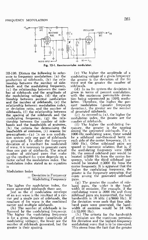
FREQUENCY MODULATION
•EBB
AUDIO INPUT )(CI
OSCILLATOR
Fig. 12-1. Reactance-tube modulator.
III-I90. Discuss the following in refer-ence to frequency modulation: (a) the production of sidebands, (b) the rela-tionship between the number of side-bands and the modulating frequency, (c) the relationship between the num-ber of sidebands and the amplitude of the modulating voltage, (d) the rela-tionship between percent modulation and the number of sidebands, (e) the relationship between modulation index, or deviation ratio, and the number of sidebands, (f) the relationship between the spacing of the sidebands and the modulating frequency, (g) the rela-tionship between the number of side-bands and the bandwidth of emission, (h) the criteria for determining the bandwidth of emission, (i) reasons for pre-emphasis.—( a ) :n an a-m modula-tion system only one pair of sidebands is generated. To effect the frequency deviation of a resultant fm modulated rf wave, it is necessary to generate more than one pair of siciebands. The actual number of sideband pairs that make up the resultant fm wave depends on a factor called the modulation index. The modulation index stated as an equation is
Modulation Index Deviation in Frequency Modulating Frequency
The higher the modulation index, the more generated sidebands there are.
Just as the rf modulation envelope of an a-m wave is the resultant of a car-rier and a single pair of sidebands, the resultant rf fm wave is the combined carrier and multiple sidebands.
(b) The number of sidebands is in-fluenced by the modulating frequency. The higher the modulating frequency is for a given deviation (amplitude of modulating voltage), the fewer are the number of sidebands generated, but the greater is their spacing.
e RFC
263
(c) The higher the amplitude of a modulating voltage of a given frequency the greater is the deviation of the fm wave and the greater the number of sidebands.
(d) In an fm system the deviation is given in terms of percent modulation, with the maximum permissible devia-tion being represented as 100% modu-lation. Therefore, the higher the per-cent modulation ( greater frequency deviation), the greater are the number of generated sidebands. ( e) As covered in ( a), the higher the
modulation index, the greater are the number of sidebands.
(f) The higher the modulating fre-quency, the greater is the spacing among the generated sidebands. For a 1000-Hz modulating wave, there would be a sideband one-thousand hertz on each side of the center frequency, (f,. -±-1000 Hz). Other sideband pairs are spaced in harmonic relation; that is, if the modulating frequency were 1000 Hz, the second sideband pair would be located 172000 Hz from the center fre-quency, while the third sideband pair would be located ±-3000 Hz from the center frequency. It is apparent that the higher the modulating frequency, the greater is the frequency separation that exists among the generated sideband pairs.
(g) The greater the number of side-band pairs, the wider is the band-width of emission. For example, if the modulating wave is 3000 Hz and three sideband pairs are transmitted, the total bandwidth is 18 kHz ( ±-9000 Hz). If the deviation were such that four side-band pairs were generated, the band-width of emission would be 24 kHz ( -±12,000 Hz).
(h) The criteria for the bandwidth of emission are the maximum permissi-ble deviation and the highest-frequency modulating wave that is to be conveyed. This stems from the fact that the greater

264 SECOND-CLASS RADIOTELEPHONE LICENSE HANDBOOK
the deviation, the greater is the num-ber of generated sidebands, and the higher the frequency of the modulating wave, the greater is the frequency separation among sidebands. Thus, a station which is assigned a maximum-permissible deviation of -.±15 kHz ( 100% modulation) will occupy a greater span of frequencies (channel width) than a station which is assigned a maximum-permissible deviation of ±-5 kHz ( 100% modulation). A station which is permitted to transmit a maxi-mum-modulation frequency of 15,000 Hz will occupy a greater span of fre-quencies than one which is assigned maximum audio frequency of 3000 Hz per a given frequency deviation. The above criteria are often expressed
in the form of a deviation ratio:
Deviation Ratio
Maximum Permissible Deviation = Highest Modulating Frequency
(i) A frequency modulation system is less susceptible to noise. However, its noise-rejection characteristics are more favorable at low modulating fre-quencies than they are at high modu-lating frequencies. For this reason, a system of pre-emphasis is used to ob-tain better overall signal-to-noise ratio. This is accomplished by permitting the higher-frequency components (per a given initial amplitude of modulating wave) to cause a greater deviation of the fm wave as compared to a lower-frequency component of the same mag-nitude. Before the audio is reproduced at the receiver, it is passed through a de-emphasis network which restores the frequency components of the modulat-ing signal to their initial magnitude as existed prior to preemphasis.
111-191. Discuss wide-band and nar-row-band reception in fm voice-com-munication systems with respect to de-viation and bandwidth.—The greater the frequency deviation of an fm wave per a given audio bandwidth, the better are the interference and noise-rejection characteristics. However, the resultant bandwidth of emission is also greater.
Bandwidth is of concern when so many radio services require a frequency spectrum. However, the benefits of fm transmission can be made available by reducing the maximum permissible de-viation and, at the same time, limiting the maximum frequency of the modulat-ing wave. This technique is particularly
adaptable to voice communications, in which case the intelligibility is not af-fected adversely by limiting the highest audio frequency to 2500 to 3000 Hz. Thus, with a maximum permissible de-viation of ±-5 kHz, and in some cases ±-15 kHz, the desirable characteristics of frequency modulation can still be obtained.
Such a technique would not be ap-plicable to fm broadcasting where the required highest modulating frequency • is 15,000 Hz and higher. Under this circumstance a much greater deviation is appropriate if the good characteris-tics of fm transmission (dynamic range and frequency response) are to be ob-tained.
In narrow-band fm transmission, the receiver need only have a narrow-band response, and a very favorable sensi-tivity and selectivity can be obtained.
In the strictly two-way radio services it has been customary to call -±-15 kHz deviation wide-band fm and -±5 kHz deviation narrow-band fm. The advan-tage, of course, of the narrow-band -±5 kHz deviation is that the emission band-width can be at least half of that re-quired by the wider-band deviation. This is referred to as split-channel oper-ation because the previous wide-band channels ( -±15 kHz deviation) have been split in half in such a manner that the same frequency space can be occu-pied by two narrow-band channels ( kHz deviation ).
111-192. How is good stability of a re-actance-tube modulator achieved?—In assigning fm channels to radio stations, the FCC requires that the carrier or center frequency of the fm wave be maintained within a close tolerance. When a reactance-tube modulator is used, it is customary to employ a self-excited oscillator that is frequency mod-ulated. Such an oscillator is subject to frequency drift, and any drift in the operating characteristics of the reac-tance tube can also produce an unde-sired center-frequency shift of the oscil-lator. A feedback afc system (Fig. 12-2) is used to maintain both the cen-ter-frequency stability of the oscillator and the operating stability of the reac-tance-tube modulator. The output of the frequency-modulated oscillator is supplied to a divider chain and a fol-low up phase detector. A second signal for the phase detector is derived from a highly stable crystal oscillator through a second divider chain. The two fre-

FREQUENCY MODULATION
AUDIO
AUDIO
AMP
PRE-LFAPHASIS
CRYSTAL
OSC
SELF EXCITED
OSCILLATOR
REACTANCE TUBE
TO AFC
TO MULTIPLIER AND AMPLIFIER
DIVIDER F_
1/3 1141 U4 115
DC ERROR VOLTAGE
DIV IDER 1/5 PHASE
DETECTOR
Fig. 12-2. Afc system used to stab luxe the reactance-tube modulator
quency components are compared in the phase detector. If there has been any drift in the zenter-frequency output of the frequency modulated oscillator, a de error voltage is developed, and it is applied as a controlling de bias to the reactance tube. This will change the center-frequency reactive component placed by the reactance tube across the tank circuit of the oscillator, which will make a suitable correction in its center frequency.
111-193. Explain, briefly, what occurs in a waveform if it is phase modulated.— Phase modulation is an indirect means of generating an fill wave. In the process, the phase of the center fre-quency is varied and is made to lead and lag its initial phase in accordance with the modulating wave. The fre-quency of the resultant wave also changes because a phase lead or lag changes the period of the rf wave, which results in a frequency change as well. The waveform in Fig. 12-3 demon-
strates the influence of phase lead or lag on the resultant frequency. The il-lustration shows a resultant phase-modulated wave. A phase lead is indi-cated between the second and third peaks. At the third peak the resultant wave is leading that which would be the phase of the unmodulated center frequency (dashed curve). It is to be noted that the period (as represented between peaks' is now shorter than for the unmodulated condition. This means that the frequency of the resultant wave has increased. The influence of a phase lag is
shown between peaks six and seven.
265
CENTER
FREQUENCY
I 2 3 4 5 6 7 8 9
PM RESULTANT
MODULATED RF UNMODULATED RF
Fig. 12-3. The phase-modulated wave.
Now the peak of the seventh wave comes late with respect to the peak of an unmodulated condition. Therefore there has been an increase in the wave period and a resultant lower frequency. In the actual modulation process, the shift in phase is made to be gradual, and therefore there is also a gradual change in frequency, just as in the case of the direct fm process.
111-194. Draw a circuit diagram of a phase modulator. Explain its operation. Label adjacent stages.—Such a modu-lator is shown in Fig. 12-4. The output voltage (E.) of the rf oscillator follows two paths—one path is through capaci-tor Cl to the control grid of the phase modulator as rf voltage E., and the other path is directly to the plate cir-cuit of the modulator through capacitor C2, as rf voltage E. Two rf compo-nents, therefore, appear in the plate circuit of the modulator; one compo-nent is E,, and the other is E2. The latter has been developed through the operation of the modulator tube with the application of the rf component (E.) to its control grid. Ordinarily, because of the polarity shift of the tube, the two components would bc out of phase. However, the reactances of Cl and C2 have been selected to establish a proper phase relationship between the two rf voltage components E, and E2, as shown in the vector dia-gram. These two components combine vectorially in the plate circuit to pro-duce a resultant output voltage (E0)• The important thing to recognize in
the vector diagram is that the phase an-gle of Ec, depends on the magnitude of the E2 component that is present in the
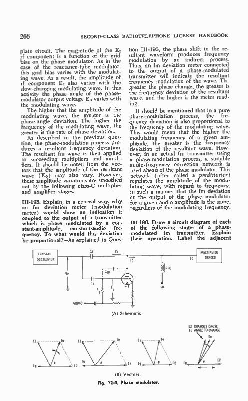
266 SECOND-CLASS RADIOTELEPHONE LICENSE HANDBOOK
plate circuit. The magnitude of the E. rf component is a function of the grid bias on the phase modulator. As in the case of the reactance-tube modulator, this grid bias varies with the modulat-ing wave. As a result, the amplitude of rf component E. also varies with the slow-changing modulating wave. In this activity the phase angle of the phase-modulator output voltage E0 varies with the modulating wave. The higher that the amplitude of the
modulating wave, the greater is the phase-angle deviation. The higher the frequency of the modulating wave, the greater is the rate of phase deviation.
As described in the previous ques-tion, the phase-modulation process pro-duces a resultant frequency deviation. The resultant fm wave is then applied to succeeding multipliers and ampli-fiers. It should be noted from the vec-tors that the amplitude of the resultant wave (E0) may also vary. However, these amplitude variations are smoothed out by the following class-C multiplier and amplifier stages.
HI-195. Explain, in a general way, why an fm deviation meter (modulation meter) would show an indication if coupled to the output of a transmitter which is phase modulated by a con-stant-amplitude, constant-audio fre-quency. To what would this deviation be proportional?—As explained in Ques-
CRYSTAL
OSCILLATOR
tion III-I93, the phase shift in the re-sultant waveform produces frequency modulation by an indirect process. Thus, an fm deviation meter connected to the output of a phase-modulated transmitter will indicate the resultant frequency modulation of the wave. Th_ greater the phase change, the greater is the frequency deviation of the resultant wave, and the higher is the meter read-ing.
It should be mentioned that in a pure phase-modulation process, the fre-quency deviation is also proportional to the frequency of the modulating wave. This would mean that the higher the modulating frequency of a given am-plitude, the greater is the frequency deviation of the resultant wave. How-ever, in an actual fm transmitter using a phase-modulation process, a suitable audio-frequency correction network is used ahead of the phase modulator. This network (often called a predistorter) regulates the amplitude of the modu-lating wave, with regard to frequency, in such a manner that the fm deviation at the output of the phase modulator for a given audio amplitude is the same, regardless of the modulating frequency.
III-196. Draw a circuit diagram of each of the following stages of a phase-modulated fm transmitter. Explain their operation. Label the adjacent
(A) Schematic.
E2 CHANGES CAUSE Eo ANGLE TO CHANGE
Eo
E2
(B) Vectors.
Fig. 12-4. Phase modulator.

FREQUENCY MODULATION
stages: (a) frequency multiplier (doubler) with capacitive coupling on input and output; (b) power amplifier with variable-link coupling to antenna (include a circuit for metering grid and plate currents); (e) speech ampli-fier with an associated pre-emphasis circuit.—A difference in the amplifica-tion and multiplication of an fm wave as compared to an a-m wave should be mentioned first. When an a-m modula-tion envelope is supplied to a frequency multiplier or class-C amplifier, it is dis-torted because the amplifier does not respond in a linear manner to the am-plitude variations of the envelope. An fm wave, however, has a constant am-plitude; it changes only in frequency. Thus, it is possible to amplify and step up in frequency an fm wave, with a class-C amplifier or multiplier, without introducing distortion.
(a) A frequency doubler with ca-pacitive input and output coupling is
OSCILLATOR-MODULATOR OR PREVIOUS I-1 MULTIPLIER I
1 R DR IVEIR
MICROPHOW
267
shown in Fig. 12-5A. The input circuit is driven by a signal of the fundamental frequency; the output tank circuit is tuned to the second harmonic. The op-eration of frequency multipliers and doublers was covered in Questions III-136 and 111-138.
(h) A class-C power amplifier with variable link coupling to an antenna system is shown in Fig. 12-5B. The grid and plate-current meters show the dc component of grid and plate current; the meters are bypassed with rf filter capacitors to keep radio-frequency en-ergy out of the meter movements. The operation of such an amplifier was cov-ered in detail in Question 111-128. The individual cycles of constant-amplitude fm draw bursts of plate current which shock-excite the output tank circuit. Since the spacing among the plate-cur-rent bursts varies as the result of the fm wave applied to the input circuit, there will be a similar frequency change in
(A) Frequency doubler.
VARIABLE-LIP« COUPLING
tee (B) Power amplifier with variable-link coupling.
LOW VALUE
PRE-EMPHASIS
RI
MULTIPLIER CIR RF POWER
AMP
V- FELALA..NCED ANTENNA
ANTENNA TUPER
ERS eito
(C) Speech amplifier.
Fig. 12-3. Stages of a phase-modulated fm transmitter.
TO MODULATION LIMITER AND FM MODULATOR

268 SECOND-CLASS RADIOTELEPHONE LICENSE HANDBOOK
the rf waves developed across the out-put tank circuit. Inasmuch as the peak value of the plate-current bursts are of constant amplitude, the rf wave de-veloped across the plate tank circuit will also be of constant amplitude, but of varying frequency. The resonant cir-cuits of the fm transmitter must, of course, have the appropriate bandwidth (Q) to accommodate the emission band-width of the generated fm signal. The variable link coupling permits
the tank circuit to be loaded properly. By changing the coupling between the link and the tank-circuit inductor, a proper load can be reflected for opti-mum operation of the stage. The tighter the coupling is, the greater is the re-flected load, as will be indicated by an increase in the reading of the de plate-current meter. The loading is adjusted until the plate-current reading corre-sponds to optimum operation of the stage.
(e) A typical speech-amplifier system for an fm transmitter is shown in Fig. 12-5C. The pre-emphasis network is a simple series resistor-capacitor com-bination ( RICI ). The reactance of the low-value capacitor decreases with fre-quency. As a result, with an increase in the audio frequency a higher percentage of the output voltage that is developed in the plate circuit of the first speech amplifier is transferred to the grid of the second stage. A 2000-Hz note as it appears in the plate circuit of the first stage would appear at higher amplitude at the grid of the second stage than a 500-Hz note of the sanie initial ampli-tude. Thus the 2000-Hz note would cause a greater frequency deviation of the transmitter, as is required in a pre-emphasis system. The two audio compo-nents will be restored to a like ampli-tude by a de-emphasis network located at the output of the fm detector of the fm receiver.
III-197. Could the harmonics of an fm transmission contain intelligible modu-lation?—Yes, for the same reason that the frequency of an fm wave can be multiplied without encountering distor-tion (in frequency multiplying we em-phasize a harmonic component of a wave), the harmonics from an fm trans-mitter could also contain intelligible modulation. In the harmonic-generating process, both the center frequency and the deviation are multiplied. For exam-ple, a 150-MHz wave with a deviation of -±1.5 kHz would have a second har-
monic component of 300 MHz, with a -±30-kHz deviation.
12-2. FM MAINTENANCE
III-198. Assume that you have the fol-lowing instruments available: ac-dc vtvm, ammeter, heterodyne-frequency meter (0.0002% accuracy), absorption wavemeter and fm modulation meter. Draw and label a block diagram of a voice-modulated ( press-to-talk micro-phone ), indirect (phase-modulated) fm transmitter having a crystal multi-plication of 12. (a) If the desired out-put frequency were 155.460 MHz, what would be the proper crystal fre-quency? (b) Assume transmitter strip completely detuned, ammeter jacks in multiplier control-grid circuits and final amplifier control-grid and cathode cir-cuits. Explain, in detail, step by step, a proper procedure for tuning and align-ing all stages except the plate circuit of i nal power amplifier ( pa ). (e) As-,ume a tunable antenna with adjust-able coupling to the plate circuit of the final pa. With the ammeter in the cathode circuit of the pa, and with the aid of a tube manual, describe a step-by-step method of obtaining maximum power output, without damage to the tube. (d) If the pa in (c) were a pentode, how would you determine the power input of the stage? (e) In (e), how would you determine if the pa stage is self-oscillating? If so, what adjustment can be made? (f) Assume that the transmitter's assigned fre-quency is 155.460 MHz, with a re-quired tolerance of -±0.0005%. What would be the minimum and maximum frequencies, as read on the frequency meter, which would insure the trans-mitter being within tolerance? (g) As-sume that the 1-megahertz crystal os-cillator of the frequency meter has been calibrated with WWV, and that the meter is tunable to any frequency be-tween each 1-MHz interval over a range of 20 to 40 MHz, with usable harmonics up to 640 MHz. Explain in detail what connections and adjust-ments would be made to measure the signal directly from the transmitter, also by means of a receiver. (h) In check-ing the frequency deviation with the modulation meter, would you expect a greater deviation to be caused by whis-tling or by speaking in a low voice into the microphone? (i) If the transmitter contains a means of limiting, and is overmodulating, what measurements

FREQUENCY MODULATION
CRYSTAL OSCILLATOR
12. 955MHz
PHASE
MODULATOR
PUSH-TO- TALK SW ITCH ANTENNA AND
AUDIO
AMPLIFIER
POWER RELAY
FIRST DOUBLER
25.91MHz
AUDIO
AMPLIFIER
MODULATION
LIMITER
TRIPLER
77.73MHz
269
SECOND DOUBLER
155. 46MHz
RF DRIVER
Fig. 12-6. Phase-modulated fm transmitter.
and adjustments could be made to de-termine and remedy the fault?—A func-tional block diagram of such an fm transmitter is shown in Fig. 12-6. A particular advantage of phase modula-tion (pm) over frequency modulation (fm) is that a crystal-controlled oscil-lator can be used. This helps in main-taining the cente--frequency stability re-quired by the Federal Communications Commission. If direct frequency modu-lation of a self-excited oscillator (fm) were used, an elaborate afc system would be required to maintain the car-rier (center frequency) stability needed.
(a) The proper crystal frequency would be 12.955 MHz (155.460/12).
(b) The ammeter jacks provide points of insertion for an ammeter to measure the con:rol-grid current in the multipliers and the power amplifier. Inasmuch as the meter is to be inserted in control-grid circuits, it will indicate maximum when there is maximum rf excitation of the stage with which the meter is associated. Hence, as the vari-ous resonant circuits are tuned, the resonant setting that permits the maxi-mum transfer of power to the next stage will be inticated by a maximum meter reading in the grid circuit of that stage. The crystal oscillator of the trans-
mitter usually will not include an out-put tuning adjustment if it operates at the fundamental frequency. However, if the crystal also serves as a frequency doubler, an output resonant circuit will be present. The alignment usually be-gins by making certain that the proper crystal is plugged in and that operation is on the correct frequency. A very fine adjustment of the transmitter frequency can be made later. Connect a dummy load.
POWER AMPLIFIER
—a- ANTENNA
In the alignment procedure the am-meter is first inserted into the grid-current jack of the first doubler. If there are any peaking adjustments in the crystal oscillator or phase modulator, they are set for a maximum meter read-ing. The ammeter can now be moved to the jack associated with the grid cir-cuit of the tripler. The first doubler resonant circuits are now adjusted for a maximum reading on the meter. In most designs the range of adjustment of the first-doubler tuning control is such that only one peak is obtained; this peak occurs at twice the frequency of the input. However, it is possible that the range of adjustment of a multi-plier-tuning control could extend to the fundamental frequency or, perhaps, even to the third-harmonic frequency. An absorption wavemeter, held near the output of the doubler or the input to the the tripler, will identify the proper harmonic. In this case the output of the doubler should be tuned to ap-proximately 26 MHz. The ammeter can now be moved to
the grid-current jack at the input of the second doubler. The tripler resonant cir-cuit is now peaked for a maximum meter reading. Again there is a possi-bility, in certain designs, that the tripler stage could be tuned to the second- or fourth-harmonic frequency of the input wave. The absorption wavemeter is again used for harmonic identification; the proper harmonic is approximately 78 MHz, not 52 MHz or 104 MHz. The ammeter is now moved to the
grid jack of the rf driver stage. The second doubler circuit can now be reso-nated for maximum grid-current read-ing. As before, there will probably be only one adjustment which will provide a maximum reading. However, it is

270 SECOND-CLASS RADIOTELEPHONE LICENSE HANDBOOK
again wise to check to make certain it is not a fundamental or third-harmonic output. In this case, the output fre-quency should be the transmit fre-quency of 155.46 MHz. The ammeter is now transferred to
the grid jack of the power-amplifier out-put stage. The driver resonant circuit and the input resonant circuit of the power amplifier are now peaked for a maximum grid-current reading. In many transmitters it is possible to adjust the power-output level of the rf driver. In this case, the rf drive level is adjusted until a certain grid-current reading is obtained, with the driver and the PA input resonant circuits tuned to reso-nance. Driver and power-amplifier cir-cuits are tuned to the transmit fre-quency of 155.48 MHz.
(c) After the rf stage has been aligned, it is necessary to tune the final power amplifier. This involves reso-nating the plate tank circuit, as well as adjusting the load to transfer maximum power to the antenna system without exceeding the tube ratings. In most cases the supply voltage is known, or it can be measured. The tube manual can then be used to determine the proper cathode current (plate current plus screen-grid current for a multigrid- type) for optimum operation in the
particular class of service and frequency of operation. Under most circumstances the appropriate operating conditions can be obtained by referring to the mainte-nance manual for the particular trans-mitter. Many higher-powered rf amplifiers
require that the initial alignment be done with a low supply voltage and a prescribed amount of loading (usually just enough light loading to prevent the development of excessively high rf voltages in the output tank circuit). The use of a lower than normal supply voltage minimizes the danger of having the tube draw excessive current during the initial tune-up procedure. Also, if the stage must be neutralized, this should be handled before the full sup-ply voltage is applied. Many modern transmitters do not require neutraliza-tion.
As per (b), the input resonant cir-cuit, if tunable, is peaked for a maxi-mum grid-current reading. The magni-tude of the rf excitation, if adjustable, is set until a particular value of grid current occurs when the input resonant circuit is peaked. The ammeter can now be moved to the cathode-current jack of
the power amplifier. The plate resonant circuit can now be adjusted to reso-nance by tuning for a maximum dip in the reading of the cathode-current me-ter. Maximum supply voltage can now be applied and the plate tank circuit retuned very finely for a maximum dip. The loading can now be increased grad-ually as the plate tank tuning is re-touched slightly. Now there will be a higher cathode reading at the dip. Addi-tional loading is now permissible, and the loading is increased until the rated cathode current is drawn when the plate tank circuit is set to resonance.
It is advisable to tune up the power amplifier working into a dummy an-tenna load to prevent radiating a signal and possible interference. The dummy load can well be an rf power-output meter that will also read the transmitter output as the adjustments are made. The dummy load, of course, should dis-play the same resistance as the antenna system. Hence, when the antenna is connected to the output of the trans-mitter, only a minor readjustment of loading and plate circuit resonance is needed to establish optimum operating conditions. Check the transmit fre-quency, modulation and power input to insure compliance with FCC regulations.
(d) The dc power input to the plate circuit is the product of the plate sup-ply voltage and the plate current. Inas-much as the cathode-current meter also indicates screen-grid and control-grid currents, the value for the plate current can be obtained by first subtracting the sum of the control-grid and screen-grid currents (obtained by measurement or approximated by reference to the tube manual) from the cathode-current me-ter reading.
In some cases the stated dc power input is based on the sum of screen grid and plate currents times the sup-ply voltage.
(e) If the pa were self-oscillating, it would have an output even though the rf excitation were removed. The ab-sorption wavemeter could be used to check for its presence. If the self-oscil-lation is on or near the frequency at which the amplifier is to operate, the stage would have to be neutralized to eliminate the problem. Refer to Fig. 10-15.
If self-oscillation is occurring on a frequency far removed from the operat-ing frequency, the trouble is parasitic self-oscillation. Parasitics are reduced using the procedures given in Questions

FREQUENCY MODULATION
111-135 and 111-157. In most transmit-ters the parasitics have been eliminated in the design, and it is more likely that the oscillations result from improper neutralization of the stage.
(f) The reading would have to be es-tablished within 0.0003% (0.0005 — 0.0002 ). Thus the minimum and maxi-mum readings that would be acceptable are
155.46 MHz -± (0.000003 x 155.46) or
155.45 MHz ± 466 Hz
Keeping the frequency meter reading within these two extremes would ensure that the transmitter frequency would be within the required tolerance of 0.0005% using a heterodyne-frequency meter with an accuracy of 0.0002%.
HETERODYNE - FREQUENCY METER
DUMMY LOAD
TRANSMITTER
DUMMY LOAD
t
TRANSMITTER
HETERODYNE
SECTION
CALIBRATED SIGNAL
GENERATOR
RECEIVER
AUDIO OUTPUT
HEADSET
H TERODYNE - FREQUENCY METE
HE
SECTION
CALIBRATED
SIGNAL
GENERATOR
Fig. 12-7. Basic heterodyne-meter test ar• rangements.
(g) The test blocks ( Fig. 12-7) show two typical arrangements for making the signal-frequency measurements. A heterodyne-frequency meter means that heterodyning facilities are available that present either an aural or visual display of a zero beat between two signals, one of known frequency and one of un-lalown frequency.
In arrangement A, the signal to be measured is picked up from the trans-mitter and applied to the input of the heterodyne-frequency meter. At the same time, the calibrated signal gen-erator of the heterodyne-frequency me-ter can be switched to apply a cali-brated comparison signal to the hetero-
271
dyning portion of the meter. When the frequency meter is set to an appropriate fundamental or harmonic, there is a beat with the incoming signal, and an aural or visual display will show when the two are set to exactly the same frequency.
In our example, the fourth harmonic of the signal generator can be used in making the frequency check. To make the fourth harmonic available at the transmit frequency to be measured, it is necessary to set the signal generator on 38.865 MHz ( 155.460/4). The 20- to 40-MHz fundamental-fre-
quency range is such that the fifth or sixth harmonic could have been used as well. However, it is customary to use the lowest order of harmonic in terms of output level, convenience, and less trouble with spurious beats. A receiver can also be used for estab-
lishing a beat between the transmitter signal and a signal from the generator portion of the heterodyne-frequency meter. The output of the signal gen-erator is applied to the input of the re-ceiver. The same receiver can also pick up the transmit signal.
There should be proper isolation or separation between the transmitter and receiver so as not to overload the re-ceiver. The receiver can be adjusted to tune in the transmitter signal. Then the heterodyne-frequency meter can be set to 38.865 MHz and a comparison made between the transmitter frequency and the fourth harmonic of the signal gen-erator.
This latter arrangement is useful in checking the frequency of operation of mobile units from a base-station test location or, for that matter, to check the frequency of any incoming signals.
(h) A greater deviation is obtained by whistling rather than by speaking in a low voice into the microphone. In making oscilloscope observations, the use of a whistle permits a check to be made with a type of signal that ap-proaches a sinelike waveform. Speech reproduces as a much more random and irregular waveform.
(i) An fm deviation meter can be used to make the measurement. If the transmitter is overmodulated when you are speaking into the microphone (de-viation peaks in excess of' the FCC deviation tolerance), there is a possi-bility of a fault in the speech amplifier-modulator section of the transmitter or, more than likely, the deviation control of the transmitter requires adjustment.

272 SECOND-CLASS RADIOTELEPHONE LICENSE HANDBOOK
This control sets the level of signal that is applied to the modulator as a func-tion of the microphone-input signal level. It is adjusted so the limiting will occur regardless of how high the input-signal level becomes, and under no cir-cumstance should there be ovennodula-tion. Limiting can be too severe. If it occurs too early, there is a possibility of distortion when you speak into the microphone at a normal voice level. A combination of a modulation meter
and an oscilloscope display are useful in making a modulation adjustment. The modulation meter is helpful in making certain that the maximum devi-ation is not exceeded, and the oscillo-scope display shows the degree of limit-ing that the signal encounters. Usually the manufacturer of the transmitter sug-gests specific levels of audio-signal in-put, and an ac vtvm can be used in setting proper signal levels. Usually a 1000-Hz audio sine wave is used in making modulation adjustments.
III-I99. What might be the effect on the transmitter frequency if a tripler stage in an otherwise perfectly aligned fm transmitter were slightly detuned? —A slightly detuned tripler stage might have some influence on the power level of the transmitted signal because of re-duced drive to the following stages. However, it would have no effect on frequency, since frequency is deter-mined by the basic rf oscillator; carrier and side frequencies may be shifted in relative phase, producing distortion. However, if the tripler were detuned a substantial amount so as to operate on its second or fourth harmonic, the out-put frequency might be at some fre-quency far removed from the desired transmit frequency.
III-200. Under what usual condition of maintenance and/or repair should a transmitter be retuned?—A transmitter should be retuned when measurements indicate that it is not operating effi-ciently, or not in compliance with FCC technical requirements. Such adjust-ments can only be made by an FCC-licensed first- or second-class operator. Adjustments which influence frequency and modulation and, in some cases, power input or rf power output should be made only when the test instrumen-tation is of an accuracy that can mea-sure well within established FCC tol-erances. Retuning is often necessary when certain tubes or transistors or
other components that are closely asso-ciated with resonant circuits and/or the modulation stages are replaced.
III-20I. If an indirect fm transmitter without modulation is within carrier-frequency tolerance, but with modula-tion is out of tolerance, what are some of the possible causes?—Two causes of a shift in oscillator frequency are changes in the oscillator supply volt-ages with modulation and changes in oscillator loading with modulation.
Another possibility, if the oscillator is supplied from a regulated voltage source, is a fault with the regulator cir-cuit, causing a supply voltage change under the changing conditions of modu-lation level. Of course, a similar change in supply voltage might result from a failure in the decoupling circuits along the supply line. With modulation, a fault in the phase modulator might re-flect a change in loading to the oscil-lator. This might be a result of mis-tuning, too strong a modulating wave, or a bad modulator tube or semicon-ductor.
III-202. In an fm transmitter what would be the effect on antenna current if the grid bias on the final power am-plifier were varied?—The rf power am-plifier of an fm transmitter is operated class-C. If the power-amplifier stage re-ceives most or all of its class-C grid bias from an external power source, then a change in that grid bias (assuming a constant level of rf excitation) would influence the power output of the trans-mitter, and there would be a decrease in antenna current with an increase in the external grid bias.
If the power-amplifier stage is signal-biased, some self-adjustment takes place because the bias is controlled by the level of the rf excitation to the stage. In general, as the rf excitation falls off, the grid bias declines, and initially there may be only a slight decline in output. However, when the loss of excitation is significant, the grid bias declines, and the stage begins to operate in a less efficient manner. Therefore, there is less power output and the antenna-current meter reading will decrease. The question is difficult to answer in
a precise manner because the power output is largely a function of three con-ditions; these are the level of the rf ex-citation, the grid bias, and the efficiency of the amplifier, which is related to both the previous operating conditions.

FREQUENCY MODULATION
12-3. FM RECEIVERS
III-203. Draw a schematic diagram of each of the following stages of a super-heterodyne fm receiver. Explain the principles of operation, and label the adjacent stages: (a) mixer with in-jected oscillator frequency, (b) i-f am-plifier, (c) limiter, (d) discriminator, (e) differential-squelch circuit.—( a ) A mixer-oscillator combination is shown in Fig. 12-8. Most fm communication receivers are double-conversion types, and they employ two mixer-oscillator combinations. In the first mixer, the rf signal is supplied to the grid circuit, and the output resonant circuit of the mixer is tuned to the high i-f frequency. In the second mixer-oscillator combina-tion, the input frequency to the mixer is the high i-f frequency, while the out-put resonant circuit of the mixer is tuned to the low i-f frequency. In the example shown in Fig. 12-8, it is as-sumed that the high i-f frequency is being applied to the input of the sec-ond mixer. A triode mixer is used, and the output resonant transformer is tuned to the low i-f frequency.
Inasmuch as most fm communica-tions receivers are preset to one or more specific frequencies, the oscillators are crystal-controlled. For the operation of the first mixer, the crystal oscillator is often followed by a multiplier section to build up the frequency of the signal for proper mixing with the incoming rf signal. However, as shown in Fig. 12-8,
FROM HIGH
AMP
MIXER
R2
CI
C2
OSCILLATOR OSCILLATOR INJECT ION
TUNED TO LOW I -F
I.
-II TO LOW I-F AMP
Ear
Fig 12-8 A receiver second mixer/oscillator combination.
273
for a second mixer-oscillator combina-tion, the output of the triode crystal oscillator is supplied via a low-value capacitor (Cl) to the control grid of the mixer. This process is referred to as control-grid loca-oscillator injection. The mixer is biased on an essentially nonlinear portion of its characteristics by R2C2 so as to provide the most ef-fective nonlinear conversion. The local oscillator and incoming signal beat to-gether to develop four major signal com-ponents in the output (two fundamen-tal frequencies, plus sum and difference frequencies). However, the output reso-nant circuit is tuned only to the differ-ence frequency, while the other fre-quency components are filtered out.
LOW I-F INPUT
(A) l-f amplifier.
FROM LAST LOW I-F AMP
r1/1/
NEXT I-F
STAGE
0 Ai
DETECTOR
(B) First and second limiters.
Fig. 12-9. 1-f amplifier and limiter circuits.
( b ) A typical i-f amplifier, as found in fm communications receivers, is shown in Fig. 12-9A. It is in the low i-f amplifier of the receiver that the selectivity of the receiver is established. Usually the input to the low i-f ampli-fier is a sealed filter with an essentially flat response over the desired bandpass, and a very sharp drop-off (skirts) on the sides of the desired i-f bandpass. This use of a highly selective input filter with a good and constant selectivity characteristic minimizes off-channel sig-

274 SECOND-CLASS RADIOTELEPHONE LICENSE HANDBOOK
nal interference, and makes the align-ment of the receiver less critical and less subject to changes in tube, transis-tor, and other operating parameters. Selectivity is determined almost entirely by the sealed filter. This filter is usually a grouping of consecutive resonant cir-cuits and appropriate M-derived slop-ing combinations. A low i-f amplifier, with a wider band
response and with less critical compo-nents and alignment requirements, fol-lows the filter. The output i-f trans-former is broadly tuned and not critical. The i-f amplifier is used for reasons of gain. The level of a very weak signal is built up to the required level for limiter operation (removal of amplitude vari-ations) and proper drive of the fin de-tector.
(c) The function of the limiter is to remove any amplitude variations that appear on the incoming fin signal as a result of noise or interference. In fact, in most fin communications receivers, the gain and overall sensitivity of the receiver are such that limiting action occurs on even a very weak input sig-nal and, on occasion, with the presence of noise in the absence of the signal. A two-stage limiter is usually em-
ployed, as shown in Fig. 12-9B. The limiter stage is usually signal biased, op-erates at a relatively low plate voltage, and has low gain. Consequently, there is only a narrow-amplitude range be-tween cutoff and grid limiting, and an incoming signal variation of very low amplitude will swing between cutoff and limiting or saturation. Furthermore, a second limiter stage follows the first and there is a further confining of the signal. Many limiters operate so tightly that regardless of the level of the in-coming signal, weak or strong, they will deliver the same signal level at the output of the two-stage limiter. Thus, the follow-up fm detector can he de-signed for optimum operation on this level of applied signal. The waveforms show how the very
limited-voltage range between cutoff and limiting causes clipping of the vari-ations on an incoming signal. It might appear that the intelligibility of the modulation would be affected adversely. However, it must be recalled that the desired information is present in an fm signal in the form of a frequency change rather than an amplitude change. De-spite the clipping of the waveform, the presence of the limiter resonant circuit restores the fm signal to sine waves of Fig
constant amplitude ahead of the dis-criminator.
(d) A basic discriminator circuit is shown in Fig. 12-10. The operation of a discriminator is based on the phase relationship between two fm rf compo-nents that appear at its input. One com-ponent is coupled directly by way of capacitor Cl and appears across dis-criminator inductor Li. Another rf com-ponent is coupled via the flux lines that link the primary and secondary resonant circuits. The secondary i-f voltage, when two coupled resonant circuits are employed, differs in phase 90° from the primary voltage, and therefore is also related by 90° to the i-f voltage that has been coupled directly across inductor Li. The 90° component is divided into two segments with reference to the secondary tap. One segment appears at the anode of diode, DI, and the other appears at the anode of diode, D2. In terms of the diode anodes, these two components are 180° apart. From the discussion, it is apparent
that diode D1 is excited by two rf sig-nals (E, E3), while diode D2 is ex-cited by a signal component composed of ( E3). At the frequency to which the discriminator transformer is tuned, these two signal components are of equal amplitude. Therefore, they draw the same peak diode current, and, inas-much as the diode currents occur in opposite directions in the output circuit, there is no output from the discrimi-nator.
FROM LAST I-F AMP
(A) Schematic.
CENTER OW FREQUENCY RESONANCE
E2 E2 EDI
EDT
E1
E D2 E3
E D2
(B) Vectors.
12.10. Basic discriminator circuit.
DE-EMPHASIS
TO AUDIO AMP
ABOVE RESONANCE
E2 ED1

FREQUENCY MODULATION
When the i-f signal deviates, the sig-nal applied to the liscriminator trans-former does not remain on one fre-quency (center frequency). Rather, it deviates with the modulation, swinging on each side of the center frequency. An off-resonance frequency applied to the discriminator transformer results in secondary components E2 and E3 which lead or lag the direct voltage (E,) by more or less than 90°. Therefore, when the incoming signal deviates on one side of the center frequency, a higher re-sultant voltage is applied to the diode DI than to diode D2. Conversely, when the signal swing is on the other side of center frequency, diode D2 is driven by a higher net voltage than diode DI. Refer to the vectors in Fig. 12-10. When diode DI draws the higher cur-rent, the net output of the discriminator is positive. Conversely, when the diode D2 draws the most current, the net out-put of the discriminator is negative. How much positive or how much
negative the output swings depends on just how far the incoming signal swings away from center frequency. Thus, as the incoming fm signal deviates in fre-quency, the output voltage of the dis-criminator follows the frequency change, and a conversion is made from fre-quency change to amplitude change. The greater the deviation of the incom-ing signal, the greater is the voltage range between maximum positive and maximum negative, as developed across the output. The faster the rate of deviation of
the incoming signal, the faster is the amplitude change at the output of the
LOW VALLE
FM DETECTOR OUTPUT
BIAS FROM LIMITER
NOISE IMPULSES
NOISE
SULI LCH CONTROL
275
discriminator. In this manner, the mod-ulating wave that is present as a fre-quency change of the incoming signal is converted back to the original ampli-tude variations of the modulating wave.
(e) A differential-squelch circuit is shown in Fig. 12-11. /n fm reception, an incoming carrier causes limiting ac-tion, and the amplitude variations and noise are quieted. However, when there is no incoming carrier, the background noise and interference are amplified and can be heard in the speaker. This is an annoying condition because in the fm radiocommunication services, most re-ceivers continuously monitor the trans-mit frequency. The purpose of a squelch circuit is to quiet this back_ground when there is no incoming signal. When there is no incoming signal,
the noise output of the discriminator is high, and it is applied to a noise ampli-fier. The output of the noise amplifier is applied to a rectifier which develops a dc output voltage that appears on ca-pacitor Cl. This voltage is of a positive polarity and causes the squelch tube to conduct heavily. The current through resistor RI in the cathode circuit of the first audio amplifier (positive at cathode side and negative at the grid side) bi-ases off the first audio amplifier. There-fore the noise signal arriving at the in-put of the first audio amplifier from the discriminator through capacitor C2 is not amplified and passed on to the audio output stage and speaker. Thus the output is said to be "squelched." When a signal is received, there is a
limiting action, and a carrier is present at the discriminator. As a result, the
C2 AUDIO FROM FM DElECTOR
NOISE RECTIFIER
NEXT AUDIO STAGE
AUDIO AMP
EBB
Fig. 12-11. Differential-squelch circuit

276 SECOND-CLASS RADIOTELEPHONE LICENSE HANDBOOK
noise output of the discriminator falls off drastically, and no noise component of significance is applied to the noise amplifier. Furthermore, a de voltage resulting from limiter action biases the noise amplifier to cutoff or very low-gain operation. Therefore no noise com-ponent is rectified by the noise recti-fier. Consequently, the positive charge on capacitor Cl disappears, and the squelch tube is cut off. This permits the first audio amplifier to operate in normal manner, and the demodulated signal from the discriminator, arriving at the grid of the first audio amplifier via capacitor C2, is amplified and passed on to the audio-output stage. Thus with the reception of a signal the receiver is said to be "unsquelehed." The squelch control must be set criti-
cally so that there will be no squelch-ing action on an incoming weak signal. The squelch activity in the circuit of Fig. 12-11 is regulated by setting the bias applied to the cathode of the noise amplifier. Its level can be adjusted until the receiver just squelches in the ab-sence of signal. An incoming weak sig-nal then cuts back the noise-amplifier operation just enough to unsquelch the receiver.
III-204. Draw a diagram of a ratio de-tector, and explain its operation. A ra-tio detector is shown in Fig. 12-12. Its operation is very similar to that of a discriminator. The schematic shows that, except for the polarity of the two detector diodes and the output circuit, the two are quite similar. The ratio de-tector has an advantage in that it also provides some amplitude limiting. The input circuit conditions and i-f
voltages E,, E., and E. have the same relations with respect to each other as in the conventional discriminator discussed in III-203(d). Thus, the i-f input volt-ages influence the diode operation in a similar manner. However, the diode current is not the same. When the fre-
FROM LAST
I-F AMP
DE-EMPHASIS
DI
Fig. 12-12. Ratio detector.
TO AUDIO AMP
quency (direction of deviation) is such that the DI conducts more than D2, the charge placed on output capacitor Cl is more negative than that placed on capacitor C2. Oppositely, with a fre-quency swing to the other side of the center frequency, the negative charge on capacitor C2 is greater than the negative charge on capacitor Cl. The output is removed at the junction of the two capacitors, and therefore the output voltage is the difference between the two charges. The output swings either negative or positive, depending on which capacitor has the higher nega-tive charge. When capacitor Cl has the higher negative charge, the output swings positive, while the output swings negative when capacitor C2 has the higher negative charge. An unusual feature of the ratio de-
tector is that although the output is the differential voltage of capacitors Cl and C2, the sum of the two charges is al-ways a constant. In terms of dc current, there is a continuous motion of electrons down through resistors RI and R2 con-nected in series. This current is a func-tion of the strength of the incoming sig-nal. Inasmuch as resistors RI and R2 and capacitor C3 have a very long time constant, a de charge which corresponds to the strength of the incoming signal develops on capacitor C3, and across Cl and C2.
This de voltage is highly stable be-cause of the long time constant. There-fore, if there are any amplitude varia-tions of the average diode current, such as might occur with amplitude vari-ations on the incoming signal they are filtered out and have no influence on the differential potential developed on capacitors Cl and C2. Hence, the dif-ferential voltage becomes a function of the frequency change only.
III-205. Explain how spurious signals can be received or created in a receiver. How can these be reduced in sets hav-ing sealed untunable filters?—In two-way radio-communications, the selec-tivity of the receiver is a very impor-tant factor. Channels are spaced very near to each other, and if the selectivity is poor, there can be interference from stations operating on adjacent channels. In a similar manner interference can be the result of signals generated within the receiver because of the two conver-sion processes and their associated oscil-lators and harmonic generators. There is also a multiplicity of mixing compo-

FREQUENCY MODULATION
nents of a spurious nature. These vari-ous signal components can combine with each other, or with incoming off-frequency signals to produce interfer-ence components. Mistuning of sharply tuned i-f amplifiers can also result in instability and the generation of some undesired spurious signal components. A strong local off-channel signal can
swing one of the rf or i-f stages into nonlinear operation and lower the sensi-tivity (desensitize) of the receiver on the desired channel. Mixing components can also fall in the desired channel. The above problems are greatly mini-
mized with the use of stable and sealed untunable filters, which establish the basic selectivity of the receiver. As mentioned previously in Question III-203, such filters are most often located ahead of the low i-f amplifier. These filters have a very sharp selectivity, which greatly emphasizes the narrow bandwidth of a desired incoming signal and has a maximum rejection to off-channel frequencies. Since these filters are sealed and isolated in a manner that prevents their operating characteristics from being affected by changes in the associated stages or changes in tempera-ture, the selectivity becomes a stable and uniform response. The i-f ampli-fiers are now less critical of both align-ment and circuit variables. They can also be of a broader bandwidth and
RF FIRST AMPLIFIER MIXER
POINTS OF SIGNAL-GENERATOR CONNECTION
MULTIPLIER
FIRST
OSCILLATOR
277
made less likely to generate spurious frequency components. Of course, proper spacing of fre-
quency relative to those of nearby trans-mitters can be made in a manner that minimizes adjacent channel operations and the formation of spurious hetero-dynes.
111-206. Describe, step by step, a proper procedure for aligning an fm double-conversion superheterodyne receiver.— Such a receiver is shown in block dia-gram form in Fig. 12-13. The recom-mended alignment procedure for most two-way radio fin receivers involves the use of a dc vtvm (or a suitable high-resistance vom), and an accurate sig-nal generator that can make available the desired i-f frequencies and several rf spot frequencies.
Usually some limiter reference volt-age is recommended, and in the align-ment process a signal level should be used that maintains this reference sig-nal level at the limiter. The vtvm is attached to the limiter test point.
In a typical procedure, the signal generator, set to 1500 kHz, is connected to the input of the low i-f amplifier (usually at the output side of the un-tunable i-f filter which sets the selec-tivity of the receiver). In the align-ment of the discriminator, the vtvm is connected across half of the discrimi-
HIGH I-F AMPLIFIER \ 21.5MHz \
VTVM (LIMITER)
SECOND
MIXER
FM
DETECTOR
AUDIO
SYSTEM
Fig. 12-13. Block diagram of a double-conversion receiver, with alignment points.

278 SECOND-CLASS RADIOTELEPHONE LICENSE HANDBOOK
nator output, and the primary is peaked for maximum output. Now the vtvm is connected across the full out-put of the discriminator, and the sec-ondary of the discriminator transformer is adjusted for a zero reading. True zero is indicated when there is an increase in output if the secondary is adjusted to either side of the correct zero setting (the swing will be negative on one side of zero and positive on the other). The vtvm is now connected to read
the dc limiter voltage. As the alignment proceeds, the signal input from the sig-nal generator must be held at a level that corresponds to the suggested lim-ited voltage for alignment. The indi-vidual i-f transformers are now peaked for maximum output, proceeding from the discriminator toward the input of the low i-f amplifier.
If the second mixer-oscillator con-verter unit contains adjustable resonant circuits, the signal generator (set to 1500 kHz) can be applied to the input of the mixer. The output-mixer resonant circuit and the second-oscillator rem-nant circuit can now be adjusted for maximum dc limiter voltage. The signal generator can now be
moved to the input of the high i-f am-plifier and set to the high i-f frequency of 21.5 MHz (in the example of Fig. 12-13). Each of these included resonant circuits can now be peaked, beginning at the input of the second mixer and working back toward the output of the first mixer. Don't forget to maintain the proper test level of limiter voltage. Some fm two-way radio receivers use
double-tuned transformers with rather critical response characteristics having the required flat-topped desired band-pass and sharp drop-off skirts. Such a transformer must be aligned critically. Quite often the secondary is peaked with the primary loaded by a resistor, and then the primary is peaked with the secondary loaded by a resistor. The pre-caution is sometimes necessary to avoid tuning the secondary to a different fre-quency than the primary and thus in-troducing a so-called split-tuned charac-teristic.
In certain wide-band applications split-tuning is an advantage. For ex-ample, an overcoupled wide-band trans-former has two remnant peaks on each side of the center frequency of its re-sponse. This is referred to as a split-tuned transformer. However, in many narrow-band alignments, tuning of pri-mary and secondary to two separate
frequencies (split-tuning) is to be avoided. Too tight coupling can also cause split-tuning. The signal generator can now be
moved to the antenna or rf input of the receiver. Before applying the signal, it is first necessary to check the first local-oscillator operation. If vacuum tubes are used, oscillator operation can be ascertained by connecting the dc vtvm to the oscillator grid, and on to the grids of the following multiplier stages. When an oscillator is in opera-tion, it draws grid current, and there-fore a negative dc voltage will be de-veloped between grid and ground, or grid and cathode. Likewise, when the following multiplier stages are driven by a signal from the oscillator, there will also be grid-current readings. If the multiplier stages are tunable, they can be adjusted for a maximum reading on the meter when it is connected to the grid circuit of the following stage. The vtvm can now be reconnected
to the limiter test point. The signal gen-erator can be turned on, and an un-modulated rf signal of proper frequency applied to the receiver input. The level of applied signal should be set so that the reference voltage is read at the limiter circuit. The various if controls can now be adjusted for a maximum reading. Always maintain the limiter reference voltage as the alignment pro-ceeds. A local-oscillator injection con-trol is often included; this should now be adjusted for a maximum limiter reading.
This concludes the overall alignment of the receiver. Usually the manufac-turer will provide a sensitivity factor. For example, it may state that with a 2-microvolt signal applied to the input of the receiver, a reading that corre-sponds to the limiter reference voltage will indicate proper alignment.
III-207. Discuss the cause and preven-tion of interference to radio receivers installed in motor vehicles.—Static and sparking noises are a major source of trouble in mobile installations. There is considerable sparking and interference associated with the spark plugs and ig-nition system of a vehicle. Generators, alternators, motors, and voltage regu-lators can present noise problems. Im-proper bonding, high-resistance rub-bing grounds, and friction (rotating wheel noise) are also suspect. Spring-contact arrangements are available for reducing wheel static, and proper bond-

FREQUENCY MODULATION
IGNITION SPARK POINTS COIL
RESISTOR IN SERIES WITH ROTOR
DISTRIBU TOR
SHIELDS
BUILT-IN OR ADDED RESISTORS
17 SPARK PLUG GAPS
BATTERY
O. ToF
FILTER o 'CAPACITOR
FEEDTHROUGH CAPACITOR
VOLTAGE REGULATOR
80 GO F
4-
O. lie
tTWO-WAY RADIO GENERATOR
Fig. 12-14. Noise-reduction methods.
ing and grounding of metal parts can reduce other scraping and motion static. The principal noise reduction, how-
ever, involves the ignition and electrical system of the motor vehicle. The dia-gram of Fig. 12-14 shows how resist-ance and filter capacitors can do much in suppressing noise. Resistive spark plugs or resistive leads can be used to suppress spark interference. Filter ca-pacitors can be used to reduce inter-ference from the generator and voltage regulator.
H1-208. Briefly explain the principles involved in frequency-shift keying (fsk). How is this signal detected?— Frequency-shift keying permits the transmission of code and radioteletype signals that are less influenced by static and other noises. In regular cw code transmission, the carrier is turned off
r L UNIT ji—lxCITED OSS —
CRYSTAL OSC.
SUB CA RR IER OSC
KEY ING UNIT
POWER STAGES
279
.0041F
during the spaces and on during the marks (dots and dashes). In fsk, by using one frequency for the spaces and a second frequency for the marks, the carrier can be kept on at all times. Inas-much as the mark and space frequencies can be positioned near each other, the receiver remains under control of a carrier whether marks or spaces are be-ing transmitted.
As shown in Fig. 12-15, a frequency shift can be accomplished by using the keying circuit to shift the frequency of a self-excited transmitter oscillator be-tween two predetermined frequencies. More often, the frequency shift is ac-complished by a reactance tube. The reactance tube is used to frequency shift a low-frequency subcarrier oscil-lator. The output of this oscillator is then mixed with a crystal-controlled component to permit keying at a much
RECEIVER
BFO
DETECTOR
SPACE FILTER
MARK CHANNEL
MARK FILTER
SPACE CHANNEL
Fig. 12-15. FSK transmission system.

280 SECOND-CLASS RADIOTELEPHONE LICENSE HANDBOOK
higher frequency. A series of multipliers then builds up the frequency shift sig-nal to the desired transmit frequency. This is F2 emission.
At the receiver, a bfo (beat-fre-quency oscillator) signal is beat with the incoming two-frequency signal. In so doing, two separate audio tones are developed at the detector output. The
124. CHAPTER
output signal is then passed to a dis-criminator-filter circuit which is able to segregate the two tones, forming a mark signal and a space signal for operation of radioteletype. For aural copying of a code signal, it is only necessary to use the mark-signal component which car-ries the dots and dashes.
12 SELF-TEST
(Anstvers on page 435) 1. What is the modulation index if a 45-MHz carrier is deviated -±15 kHz by a
5000-Hz tone? A. 6. C. 15. B. 3. D. 0.33.
2. In the public safety radio service maximum deviation is A. ±--10 kHz. C. -±200 Hz. B. -±-5 kHz. D. ±-25 kHz.
3. The number of significant sidebands depends on A. audio frequency. B. amplitude of voice frequency.
4. The limiter of an fm receiver A. removes amplitude variations. B. has a limited gain.
C. carrier or center frequency. D. A and B above.
C. D. comprises all of these.
has a constant output.
5. An fm wave is a resultant wave composed of C. constant-amplitude sidebands and
varying-frequency carrier. D. none of these.
A. varying-amplitude carrier and appropriate number of sideband pairs.
B. constant-amplitude carrier and varying-frequency sidebands.
6. A resultant fm wave has A. a changing amplitude and con- C. a changing carrier frequency.
stant frequency. D. none of these. B. fixed amplitude and changing
frequency.
7. A resultant fm wave A. can be distorted by a limiter C. carries necessary information in the
that clips, form of amplitude variations. B. always has but one pair of D. is none of these.
sidebands.
8. A ratio detector A. converts frequency change to C. is an amplitude limiter.
amplitude change. B. has a dc output that corresponds
to received signal level.
9. Preemphasis in an fm system A. improves signal-to-noise ratio. B. emphasizes audio lows over
highs.
D. is concerned with all of these.
C. converts pm to fm. D. performs A and B above.
FREQUENCY MODULATION 281
10. The audio amplitude in an fm system A. varies the amplitude of the re- C. determines the amount of deviation.
sultant wave. D. affects none of the above. B. has no effect on the frequency
of the resultant wave.
11. The number of sideband pairs formed in an fm system depends on A. audio frequency. C. modulation index. B. audio amplitude. D. all of above.
12. The spacing of the fm sidebands depends on A. audio frequency. C. modulation index. B. audio amplitude. D. all of these.
13. The emission bandwidth of an fm system depends on A. audio frequency. C. modulation index. B. audio amplitude. D. all of these.
14. A grid-dip meter can be used to check for A. parasitics. B. LC resonant frequencies.
15. Too much squelch can A. increase noise output. B. increase deviation.
16. A squelch circuit A. increases sensitivity. B. improves selectivity.
C. antenna resonance. D. all of these.
C. block a weak signal. D. increase sensitivity.
C. reduces no-signal noise. D. does none of these.
17. An fm transmitter on 175 MHz is modulated with a 500-Hz tone. If four sig-nificant sideband pairs are generated, what is the emission bandwidth? A. 1000 Hz. C. 4000 Hz. B. 2000 Hz. D. 8000 Hz.
18. The greater the fm deviation A. the higher is the signal-to-noise C. the greater is the emission band-
ratio. width. B. the lower is the deviation ratio. D. A and C above apply.
19. Give the off-frequency deviation in percentage when a transmitter assigned to 12.6 MHz is operating on 12.606 MHz. A. 0.048%. C. 0.0098%. B. 0.098%. D. 0.00048%.
20. A class-C amplifier does A. distort an a-m modulation en- C. have a constant de plate current
velope. when amplifying an fm wave. B. not distort an fm wave. D. all of these.
21. What can cause a drift in center (carrier) frequency in a reactance-tube fm system? A. Low audio level. C. Shift in multiplier resonant fre-B. Change in reactance-tube grid quency.
bias. D. Improper tuning of final class-C amplifier.
22. A de-emphasis circuit A. is used in an fm transmitter. B. is part of a squelch circuit.
C.
D.
emphasizes low frequencies above highs. lowers signal-to-noise ratio.

282 SECOND-CLASS RADIOTELEPHONE LICENSE HANDBOOK
23. What circuit provides a quiet no-signal background when operating a land mobile fm receiver? A. Limiter. C. Delayed ave. B. Ratio detector. D. Squelch.
24. What step is not required when measuring transmitter frequency with a heterodyne-frequency meter? A. Check calibration of heterodyne C. Modulate transmitter and set level.
frequency meter if required. Al- D. Zero beat against calibration oscil-low warm-up time. lator and read meter or refer to fre-
B. Apply transmitter signal to fre- quency chart. quency meter.
25. A double-conversion receiver A. has two i-f frequencies. C. has improved image rejection. B. requires but one local oscillator. D. involves A and C above.

CHAPTER 13
Element Ill Antennas and lines
13-1. TRANSMISSION LINES AND WAVEGUIDES
III-209. What is meant by the charac-teristic (surge) impedance of a trans-mission line? To what physical quanti-ties is it proportional?—A transmission line has a characteristic impedance which is determined by the unit-length inductance of its conductors and the capacitance between its conductors (as influenced also by the dielectric constant of the material in the space between conductors). The value of this charac-teristic impedance is the impedance which must be connected to the output terminals of a section of line of any length to make the line appear to be in-finitely long. An approximate expression for characteristic impedance is
Z = — C
Thus it can be said that the character-istic impedance is proportional to the square root of the quotient of its in-ductance per unit length over its capac-itance per unit length.
1H-210. Why is the impedance of a transmission line an important factor with respect to matching "out of a transmitter" into an antenna?—When there is a match between the transmit-ter and the transmission line and be-tween the transmission line and the an-tenna, there is a maximum transfer of power between the transmitter and the antenna. This efficient transfer of energy occurs when the transmitter output is matched to the characteristic impedance of the transmission line, and when the antenna system at the termination end
of the line is matched to the character-istic impedance of the transmission line. When a transmission line is properly matched to an antenna system, there is a minimum radiation of radio-frequency energy from the line, eliminating a cause of energy loss or antenna-pattern distor-tion.
111-211. What is meant by standing waves, standing-wave ratio (swr), and characteristic impedance as referred to transmission lines? How can standing waves be minimized?—The definition for the characteristic impedance of a transmission line was given in Question III-209. When a transmission line is ter-minated in its characteristic impedance, all of the energy conveyed along the line is delivered to the termination. If the line is not terminated in its charac-teristic impedance, only a part of the energy moving along the transmission line is delivered to the termination. The remainder of the electrical energy is re-flected at the termination and moves back along the transmission line in the opposite direction. There is now an in-teraction between the direct rf energy and the reflected rf energy. In this case, the rf voltages and the rf currents add algebraically to set up voltage and cur-rent standing waves on the transmission line. For example, at so-called voltage loops positioned along the line, the di-rect and reflected voltages are in phase and add to produce maxima. At other positions called voltage nodes, they are exactly out of phase and they subtract to produce minima ( Fig. 13-1).
These voltages and currents can be measured with a suitable rf meter ar-rangement. The ratio between maximum and minimum voltage readings or be-
283
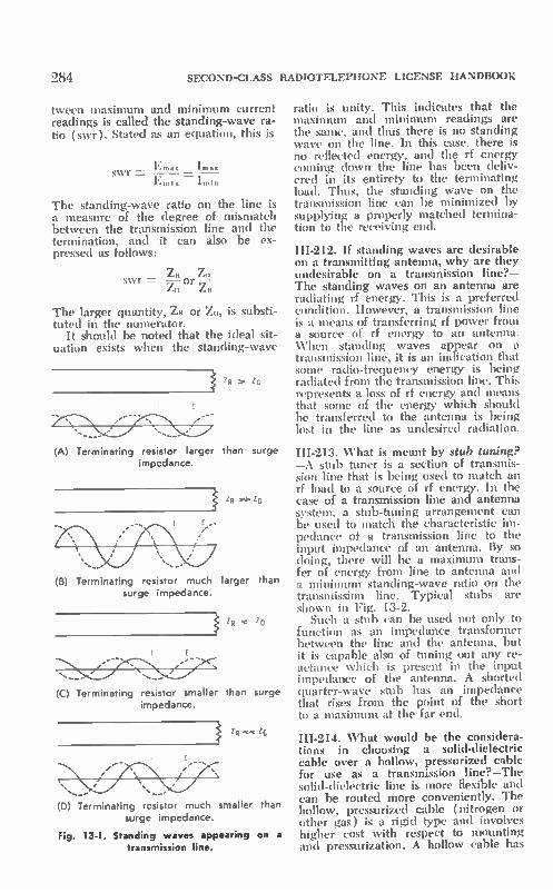
284 SECOND-CLASS RADIOTELEPHONE LICENSE HANDBOOK
tween maximum and minimum current readings is called the standing-wave ra-tio (swr). Stated as an equation, this is
swr = Im•s.
Lulu ImIn
The standing-wave ratio on the line is a measure of the degree of mismatch between the transmission line and the termination, and it can also be ex-pressed as follows:
swr = ZO 27, or fit
The larger quantity, Zit or Zo, is substi-tuted in the numerator.
It should be noted that the ideal sit-uation exists when the standing-wave
ZR Zo
(A) Terminating resistor larger than surge impedance.
ZR ><•ZO
(B) Terminating resistor much larger than surge impedance.
ZR < ZO
',—
(C) Terminating resistor smaller than surge impedance.
ZR « ZG
(D) Terminating resistor much smaller than surge impedance.
Fig. 13-1. Standing waves appearing on a transmission line.
ratio is unity. This indicates that the maximum and minimum readings are the same, and thus there is no standing wave on the line. In this case, there is no reflected energy, and the rf energy coming down the line has been deliv-ered in its entirety to the terminating load. Thus, the standing wave on the transmission line can be minimized by supplying a properly matched termina-tion to the receiving end.
III-212. If standing waves are desirable on a transmitting antenna, why are they undesirable on a transmission line?— The standing waves on an antenna are radiating rf energy. This is a preferred condition. However, a transmission line is a means of transferring rf power from a source of rf energy to an antenna. When standing waves appear on a transmission line, it is an indication that some radio-frequency energy is being radiated front the transmission line. This represents a loss of rf energy and means that some of the energy which should be transferred to the antenna is being lost in the line as undesired radiation.
111-213. What is meant by stub tuning? —A stub tuner is a section of transmis-sion line that is being used to match an rf load to a source of rf energy. In the case of a transmission line and antenna system, a stub-tuning arrangement can be used to match the characteristic im-pedance of a transmission line to the input impedance of an antenna. By so doing, there will be a maximum trans-fer of energy from line to antenna and a minimum standing-wave ratio on the transmission line. Typical stubs are shown in Fig. 13-2.
Such a stub can be used not only to function as an impedance transformer between the line and the antenna, but it is capable also of tuning out any re-actance which is present in the input impedance of the antenna. A shorted quarter-wave stub has an impedance that rises from the point of the short to a maximum at the far end.
111-214. What would be the considera-tions in choosing a solid-dielectric cable over a hollow, pressurized cable for use as a transmission line?—The solid-dielectric line is more flexible and can be routed more conveniently. The hollow, pressurized cable (nitrogen or other gas) is a rigid type and involves higher cost with respect to mounting and pressurization. A hollow cable has

ELEMENT III ANTENNAS AND LINES
very low loss and can be designed to handle extremely higq power. It can be pressurized to keep out moisture and maintain a constant resistance. The solid-dielectric cable is adaptable to standard connectors and does not in-volve extensive plumbing as do the joints, bends, etc., of rigid cable.
111-215. Describe briefly the construc-tion and purpose of a waveguide. What precautions should be taken in the in-stallation and maintenance of a wave-guide to ensure proper operation?— Waveguides are constructed of durable weather-resistant material capable of re-flecting microwave energy with a mini-mum of loss. The cross section of a waveguide can be rectangular or tubu-lar ( Fig. 13-3). There is no inner con-ductor, and the radio-frequency energy propagates along the waveguide enclo-sure much as a radio wave is propa-gated through space. However, the en-ergy is confined with:n the guide walls. A good waveguide installation has very much less loss as a means of transferring microwave energy as compared to coax-ial or parallel-conductor types of trans-mission line. Thus a waveguide func-tions as an efficient transmission line for conveying microwave energy. The dimensions of a waveguide are related to the wavelength of the signal to be conveyed; this makes the size of a wave-
LENGTH SET BY —IMPEDANCE
TRANSFORMAI ION
1/--STUB LENGTH SET RV UNE --- REACTANCE THAT MUST
BE BALANCED
(A) Twin lead.
TUNABLE STUB
(B) Coaxial.
Fig. 13-2. Stub-tuning arrangements.
285
guide impractical for use at lower fre-quencies. The efficiency of a waveguide de-
pends on the uniformity of the inner walls and the completeness with which the microwaves are reflected from the walls. Therefore the installation should be such that the interior is kept clean, smooth, and dry. Water, dust, and cor-rosion will introduce discontinuities and loss of efficiency. To minimize loss, the installation should be planned for a short and direct routing of the wave-guide. In the installation of a guide, special joints can be installed where connections or bends are to be made. These joints, called choke joints, pre-vent discontinuities from causing ob-jectionable attenuation in the transfer of the microwave energy. Just like a conventional transmission line, a wave-guide must be matched properly for most efficient operation. It must be correctly dimensioned relative to the microwave-frequency range that is to be conveyed.
III-216. Discuss the following with re-spect to waveguides: (a) relationship between frequency and size, (b) modes of operation, (c) coupling of energy into the waveguides, (d) general prin-ciples of operation.—( a ) The higher the microwave frequency of operation is, the smaller are the required physical di-mensions of a practical waveguide. As shown in Fig. 13-3A, a common dimen-sion for a rectangular waveguide is an inside width (long wall) of approxi-mately 0.8 wavelength (A), while the height (short wall) is 0.38 wavelength B (b) The mode of operation of a
waveguide has to do with the distribu-tion of the electric and magnetic field patterns in a plane transverse to the di-rection of propagation of the micro-wave energy along the line. A te mode is one that has a transverse elec-tric field, as shown in Fig. 13-3A. A tm mode is one with a transverse mag-netic field, as in Fig. 13-3C. There are a variety of both te and tm modes accord-ing to the number of complete electric or magnetic fields in a half-period dimen-sion of the microwave energy being con-veyed.
(c) There are various ways of cou-pling energy into a waveguide. In some cases it is simply the correct positioning of an aperture which leads directly into the waveguide from a microwave reso-nant circuit such as a cavity, as shown

286 SECOND-CLASS RADIOTELEPHONE LICENSE HANDBOOK
in Fig. 13-4. It is also possible to insert a probe into the rectangular cavity, as shown in Fig. 13-4B. This would be a means of transferring energy from a short coaxial feed line into a waveguide. The method of coupling depends on
the propagation mode which is to be used in the waveguide. The arrange-ment shown in Fig. 13-4B is one used to establish the te, ,. mode of Fig. 13-
iiiiiiii END VIEW
TE MODE
tuttfttt Lam it SIDE VIEW
SHOWING ELECTRIC FIELD
4
tI4444 tif ty )1
I I J1 11 11 1 \L ill( j
r --T DIRECTION Of 'PROPAGATION
TOP VIEW
SHOWING MAGNETIC FIELD IN PARI PARALLEL TO DIRECTION Of TRAVEL
- ELECTRIC LINE
-- MAGNETIC LINE
:3A. It sets up a transverse electric field and a magnetic field which is oriented parallel to the direction of propagation along the line.
((I) The transmission of microwave energy along a waveguide is in the form of electromagnetic propagation, but the movement is confined within the guide. The propagation is by means of changing magnetic and electric lines of force, which have the same signifi-cance as the rf current and voltage dis-tribution mentioned in the previous question on conventional two-conductor transmission lines. The microwave en-ergy travels within the metal enclosure of a waveguide by bouncing off the inner walls. With proper design, there is no significant penetration of the walls, and the waves are reflected from the walls with little attenuation. The chang-ing lines of force provide the continu-ous movement and completed energy loops needed to propagate within the
(B) Tubular guides.
(A) Rectangular waveguide. (C) Rectangular guide, tm_. , mode
Fig. 13-3. Basic waveguides.

ELEMENT III ANTENNAS AND LINES
(A) Cavity resonator to a waveguide.
CLOSED END OF
WAVEGW DE
TUNABLE END
PLUNGER
/ 1
FROM MICROWAVE SOURCE
(B) Coaxial feed into a waveguide.
Fig 13-4. Coupling microwave energy to a waveguide.
guide. Either the electric- or the mag-netic-field lines must be oriented in part in the direction of propagation. These two fields are, of course, perpen-dicular to each other, one creating the other to propel the energy along the guide. The dimensions of the waveguide
are important in terms of the reflec-tion of the energy from the walls. If dimension A, Fig. 13-3A, is a half wave-length, the microwave energy will bounce back and forth side-to-side at its point of couplang, and it will not propagate along the line. To have prop-agation along the line, it is necessary to have the microwave energy hit the wall at an angle as shown in Fig. 13-3A. Since the angle of reflection is equal to the angle of incidence, the wave will then be bounced side-to-side down the line. This requires that dimension A be greater than a half wavelength or, stated another way, a half wavelength at the microwave signal frequency should be significantly shorter than di-mension A. The value of 0.8 wave-length is typical.
HI-217. Explain the principles of opera-tion of a cavity resonator.—A properly dimensioned section of waveguide can be made to operate as a resonant cir-
Fig. 13-5. Resonant cavity.
CYLINDRICAL CAVITY
287
TUNING
holiit
SPHERE
cuit. Waveguide segments can be closed off into various shapes and forms, as shown in Fig. 13-5. These complete resonant enclosures are referred to as cavities. The simplest resonant cavity can be made by closing off both ends of a rectangular or circular waveguide. In so doing, there will be a circulating magnetic field similar to the circulating rf current in a conventional tuned cir-cuit. Such a cavity can be made to have an extremely high Q at the micro-wave frequency for which it has been dimensioned.
As in the case of a conventional cir-cuit, the energy is continuously ex-changed between electric and magnetic fields (comparable to the electric field across the dielectric of the capacitor and the magnetic field surrounding the coil of a conventional LC resonant cir-cuit). However, no closed electrical path is required, the energy being in the form of a confined electromagnetic wave.
HI-218. How are cavities installed in vertical waveguides to prevent moisture

288 SECOND-CLASS RADIOTELEPHONE LICENSE HANDBOOK
from collecting? Why are long hori-zontal waveguides not desirable?—A good vertical mounting should be made so as to minimize the collection of mois-ture. Appropriate choke joints should be used, and mounting gaskets are avail-able which block the intrusion of mois-ture. A choke joint ensures that a con-tinuous electrical circuit is presented within the waveguide, although there is an actual physical break between the waveguide and any inserted device, such as a joint or a cavity.
Long, perfectly level horizontal runs of waveguide are to be avoided be-
E- SECOND ALTERNATION
E-FIRST ALTERNATION
Al2
E ....... 1-••••:. , •
••••
cause they are especially prone to an accumulation of moisture which does not drain off readily and quickly.
13-2. ANTENNAS
111-219. Explain the voltage and cur-rent relationships in a one-wavelength antenna, a half-wavelength (dipole) antenna, and a quarter-wavelength grounded antenna.—The current and voltage distributions for these funda-mental antennas are shown in Fig. 13-6. When an antenna is excited with radio-frequency power, that energy moves
Al2
IMPEDANCE CHARACTERISTICS
DIPOLE ANTENNA VOLTAGE AND CURRENT DISTRIBUTION
(A) Half-wave antenna.
GROUND
MIRROR
I.
(B) Quarter-wave grounded antenna
.....- .."*: 4. .... " • •••• .. ..\ . ...• ...._ •
• ../ .. • ,. •
-A—
(C) Full-wave antenna.
Fig. 13-6. Basic antennas, and voltage-current distribution.

ELEMENT III ANTENNAS AND LINES
along the antenna conductor (s) toward the free end( s). At the ends the energy is reflected just as it would be at the far open-end of a transmission line. Thus, a standing-wave pattern of volt-age and current is set up on the an-tenna. In fact, many types of antennas become effective resonant circuits. As more and more rf energy is supplied to the antenna, oscillating rf waves break free and move out into space. A voltage maximum occurs at the
open-end points of reflection. Thus, in the case of the very common half-wave-length dipole (Fig. 13-6A), there are maximum voltage points at each an-tenna end. The half-wavelength antenna makes an efficient resonant circuit be-cause it is an electrical half wavelength in dimension (its physical length is only slightly less than a half wavelength because of capacitive end effects). In a half-wavelength antenna, the voltage distribution goes from a maximum at one end through a minimum (90e away) to a second maximum of opposite polarity at the other end of the antenna. The minimum voltage point corresponds to a maximum current point, while cur-rent minima exist at the ends.
It can be anticipated from the dis-cussed current and voltage relationship that the impedance will also vary along the length of the antenna. The imped-ance will be maximum where the volt-age is maximum and the current is minimum, while the impedance will be minimum where the voltage is min-imum and the current is maximum. Customarily, a half-wavelength antenna is a dipole type, meaning that it is divided into two quarter-wave sections and is fed at the center (Fig. 13-6A). At the center of the antenna we have noted that the impedance is minimum. Therefore, a suitable match can be ar-ranged between the d.pole antenna and the low impedance of a transmission line. The voltage and current distribu-
tion is such that the impedance pre-sented at the center seed point of the half-wavelength antenna is 72 ohms. A quarter-wavelength antenna has
the current and voltage distribution shown in Fig. 13-6B. The operational characteristics of a grounded quarter-wavelength antenna are similar to those of a half-wavelength antenna, with the exception that the ground acts as a mirror quarter-wavelength segment. Such a quarter-wavelength antenna is often fed near the ground point where
289
it has a low impedance which can be matched conveniently to a transmission line. The impedance at the ground point is theoretically 36 ohms. The voltage and current distribution
for a one-wavelength antenna is shown in Fig. 13-6C. Again there are maxi-mum voltage points at the open ends. This voltage maximum pattern is re-peated along the length of the antenna. Therefore, a maximum exists at the center of the antenna as well as at the ends. Current maxima occur at the odd quarter-wavelength points along the antenna length. From the preceding discussion it is
apparent that current and voltage rela-tions are significant in the matching and efficient transfer of energy be-tween line and antenna. The physical length of the antenna is also a factor. If the antenna is to be an efficient rf radiator, its physical length must be such that electrical resonance can be established.
111-220. What effect does the magni-tude of the voltage and current at a point on a half-wavelength antenna in free space (a dipole) have on the im-pedance at that point?—The impedance along a length of antenna is the quo-tient of the voltage and current at each particular point, i.e.,
Z='
The impedance of a dipole antenna at its usual center feed point is 72-ohms resistive in free space. The actual im-pedance in a practical installation is also influenced by the presence of ground and nearby conducting sur-faces. Dipoles can be shaped in ways other than thin, straight conductors, so as to change the center-point im-pedance.
If the dipole is fed at some point other than the center along its half wavelength, its impedance will he higher than at the center point. For example, if the antenna is fed at the end where the voltage is high and the current is minimum, the impedance is greater than 1000 ohms.
111-221. What kinds of fields emanate from a transmitting antenna, and what relationship do they have to each other? —The electromagnetic radiation from an antenna is in the fonn of changing electric and magnetic fields. As shown

.."90 SECOND-CLASS RADIOTELEPHONE LICENSE HANDBOOK
in Fig. 13-7, these fields are perpendic-ular to each other as the rf energy propagates through space. There is also an induction field about
an antenna—just as the one you would find about any type of coil. However, the induction field falls to an insignifi-cant value a short distance from the antenna, as do the flux lines of a coil.
III-222. Can either of the two fields that emanate from an antenna produce an emf in a receiving antenna? If so, how? —The radio wave is propagated through space because of the interacting influ-ence of its electric and magnetic com-ponents. Both are necessary in the ac-tivity that causes a current in the receiving antenna. The standard-length antenna has voltages (enes) induced along its length as a result of the chang-ing magnetic flux of the waves. The magnetic flux is, of course, a result of the changing electric and magnetic vec-tors of the electromagnetic wave. The voltages induced along the length of the antenna cause a current in the antenna and an associated external receiving sys-tem.
In the case of the usual straight re-ceiving antenna, the electric vector has a significant bearing in terms of the current distribution. Conversely, for loop or frame antennas, which have dimensions that are very small in com-parison to the wavelength of the in-coming signal, the activity of the mag-netic vector is of more significance in determining the current in the antenna.
III-223. Draw a sketch and discuss the horizontal- and vertical-radiation pat-terns of a quarter-wavelength vertical antenna. Would this also apply to a similar type of receiving antenna?— Refer to Fig. 13-7. The vertical quarter-wavelength antenna has an omnidirec-tional horizontal-radiation pattern. This means that, under an ideal situation, signals of uniform strength are radi-
ELECTRIC
.. ---
„
----- - - - VERTICAL PC4AR I ZATION VERTICAL PATTERN
ated from the antenna in all azimuthal directions. The quarter-wave vertical antenna above a good conductive ground has a low-angle vertical radia-tion pattern. This means that more en-ergy is radiated directly over the surface of the earth toward the horizon, and much less energy is radiated skyward. This would also be representative of the sensitivity pattern of a similar quar-ter-wave receiving antenna. It would display the same sensitivity at all com-pass angles. It would display a maxi-mum sensitivity toward signals skim-ming over the surface of the earth rather than to those signals which would be arriving at high angles (from the sky). This is referred to as the law of reciprocity; like antennas have similar radiation and sensitivity patterns.
III-224. Explain the following terms with respect to antennas (transmission or reception ): ( a ) field strength, (b) power gain, (c) physical length, (d) electrical length, (e) polarization, (f) diversity reception, (g) corona dis-charge.—( a ) Field strength has to do with the strength of an electromagnetic wave at a certain distance from a trans-mitting antenna. Customarily, electro-magnetic radiation is expressed in volts, millivolts, or microvolts per meter. This represents the voltage which would be induced into an antenna by the rf wave for every meter of its length.
(b) Power gain is a unit of compari-son between antenna types in terms of their maximum radiation intensity. It is represented as a quotient as follows:
Radiation Intensity Delivered by Antenna Under Test
Gain, = Radiation Intensity Delivered by Reference Antenna
There is no single standard reference antenna. Customarily, at high frequen-cies a half-wavelength dipole is often considered a test standard. In other
HORIZONTAL PATTERN
Fig. 13-7. Fields and patterns of a quarter-wave vertical antenna

ELEMENT III ANTENNAS AND LINES
cases the standard might be a quarter-wave vertical or an isotropic ( point-source) antenna.
Since like transmit and receive an-tennas are reciprocals, the power gain of the receiving antenna is a similar quotient. In this case, it is the power the antenna under test abstracts from the passing electromagnetic wave and delivers to the receiving load, as com-pared to the power which would be delivered when using the reference an-tenna.
(c) The physical length of an an-tenna is its linear length, so many inches or feet long. For a given-style antenna, say a half-wavelength an-tenna, the physical length of the an-tenna is usually somewhat shorter than the calculated "free-space" half-wave-length of the signal to be radiated or received.
(d) The electrical length represents the length of an antenna based on wavelength. A half-wavelength antenna has a length that displays an exact elec-trical half-wavelength resonance at the frequency to be radiated or received. As mentioned in (c), the actual physical length needed to obtain a given elec-trical length is usually slightly shorter than the calculated "free-space" half-wavelength of the signal to be received.
(e) The polarization of an electro-magnetic wave refers to the direction of its electric vector. For example, a horizontally polarized wave is one that has a horizontal electric vector and a vertical magnetic vector. Conversely, a vertically polarized wave is one that has a vertical electric vector and a hori-zontal magnetic vector (Fig. 13-7). A conventional dipole transmitting
antenna must be mounted horizontally to radiate a horizontally polarized wave, and it must be mounted vertically to radiate a vertically polarized wave. Likewise, the receiving antenna must be mounted horizontally or vertically relative to an incoming horizontally or vertically polarized wave to extract the maximum signal.
(f) In a diversity-reception system there are two or more widely spaced antennas (spaced at least far enough to reduce mutual interaction) which pick up a particular signal and deliver outputs to a common receiving loca-tion. The diversity-receiving arrange-ment is such that the antenna deliver-ing the strongest signal at the moment supplies a demodulated output for lis-tening or display. With signal fading,
291
the diversity-receiving system automat-ically selects the antenna which is re-ceiving the maximum signal. In this way a diversity-reception system can minimize the influence of fading. The output signal-level change is therefore much less than that which would be present with a single receiving antenna.
(g) Corona is an electrical discharge which occurs near the surface of a conductor when the voltage gradient exceeds a certain critical value. A fine point or conductor end would be most likely to produce a corona discharge. A mobile antenna in motion collects static charges that can build up and discharge in corona manner, produc-ing receiver noise. This is most likely to occur at a sharp point such as the end of a whip antenna. For this reason, antenna ends are often capped or balled to hold down the voltage gradient.
III-225. Discuss series and shunt feed-ing of quarter-wave antennas, with re-spect to impedance matching.—Shunt-and series-fed quarter-wave vertical an-tennas and feed arrangements are shown in Fig. 13-8. In the shunt-fed arrange-ment, the bottom of the quarter-wave antenna is grounded. An impedance match is made by proper positioning of the tap on the antenna. The higher the feed point is above ground, the higher is the impedance that the an-tenna presents to the transmission line or associated antenna-tuning unit.
In the series-fed arrangement, the bottom of the antenna is insulated from ground. The transmission line or the output of the tuning unit then connects between the bottom of the antenna and ground. The antenna resistance at this feed point is approximately 36 ohms for a quarter-wave antenna. The actual value will also be influenced to some extent by the ground conductivity.
Al4 Alit
GROUND SYSTEM
(A) Shunt fed (B) Senes fed
Fig. 13-8. Antenna-feed systems for a quar-ter-wave antenna.

292 SECOND-CLASS RADIOTELEPHONE LICENSE HANDBOOK
Thus, an impedance transformer or an-tenna tuner is often used to make an appropriate match from the transmis-sion line to the antenna feed point.
III-226. Explain why a loading coil is sometimes associated with an antenna. Under this condition, would absence of the coil mean a capacitive antenna im-pedance?—The function of a loading coil is to increase the electrical length of the antenna when its physical length is too short to permit a resonant condi-tion. Thus, as shown in Fig. 13-9, the presence of a loading coil permits the physical length of a quarter-wavelength antenna to be significantly shorter than when used without a coil.
Without the presence of the loading coil, the antenna length would there-fore be shorter than the desired quar-ter-wavelength, and it would present a capacitive antenna impedance.
III-227. What constitutes the ground-plane when a quarter-wave grounded (whip) antenna one meter in length is mounted on the metal roof of an auto-mobile? When it is mounted near the rear bumper of an automobile?—When a quarter-wave antenna that has a di-mension of only one meter is used, the dimensions of the car roof are such that the roof functions as a good ground plane. In practice, a good ground-plane action is obtained if the roof dimensions are at least one-half wavelength (diam-eter of a circular ground plane or the minimum length of the sides of a squared ground plane). Such a ground plane provides a low angle of radiation, which is preferred for mobile two-way radio application. A rear-bumper mount would display
a characteristic less ideal than a more complete ground plane, and the hori-zontal-radiation pattern would not be as uniform as with the center of the roof mounting. The car bumper, and
T A4 At
Fig. 13-9. Use of a loading coil to increase
the electrical length of a short antenna
to some extent the car body, would provide some ground-plane radial char-acteristics. If the mount is made near the center of the bumper, the two bumper sides can act as approximately two quarter-wavelength radials.
III-228. Draw a sketch of a coaxial (whip) antenna. Identify the positions and discuss the purposes of the follow-ing components: (a) whip, (b) insu-lator, (c) skirt, (d) trap, (e) support mast, (f) coaxial line, (g) input con-nector.—Such an antenna construction is shown in Fig. 13-10. Fundamentally, the coaxial whip antenna is a half-wave-length type. The whip itself, which is a continuation of the inner conductor of the transmission line, is a quarter-wave-length long, and it functions as one side of the half-wavelength vertical-dipole construction. The other quarter-wave of the basic dipole construction is in the
AM WHIP
INSULATOR
AM SKIRT
TRAP
SUPPORT MAST
COAXIAL LINE
INPUT CONNECTOR
MUST BE INSULATED SUPPORT
FLEXIBLE COAXIAL LINE FEED AND NO SUPPORT MAST
Fig. 13-10. Coaxial antenna.

ELEMENT III ANTENNAS AND LINES
form of the skirt. Signal is radiated by both the whip and the skirt.
(a) The whip is the top quarter-wave radiating section, and it is a con-tinuation of the inner conductor of the coaxial line. ( b) The insulator permits center feed
and keeps the whip and the inner con-ductor insulated from the skirt and the outer conductor of the coaxial line. ( c ) The skirt forms the lower quar-
ter-wave segment of the coaxial half-wave dipole. It is connected to the outer conductor of the coaxial line at the center feed point.
(d) The folded back quarter-wave-length of skirt acts as a quarter-wave shorted section of line, establishing a high impedance between the outer con-ductor of the coaxial line and the open end of the skirt. It functions as a parallel-resonant trap. It is this high impedance which prevents interaction between the dipole segment provided by the skirt and the coaxial line which feeds up through its center, permitting the skirt to act as a radiator.
(e) If a rigid coaxial line is being used, the outer con Juctor can also serve as the supporting mast and can be fastened to a roof mount, wall mount, car body, etc. If a flexible coaxial line is being used, an insulating mounting arrangement is required, as shown in Fig. 13-10.
(f) The coaxial transmission line provides a means of transferring a sig-nal from the transmitter to the coaxial antenna. The coaxial line is unbal-anced, but the center-feed method us-ing the skirt permits a proper imped-ance match and transformation to a balanced dipole radiator.
(g) In the rigid type of mount it is possible to install a coaxial receptacle at the base of the antenna. This recep-tacle can serve as the input connec-tion. A coaxial transmission line of the flexible type and a suitable coaxial plug can then be used as a means of con-necting the transmission line to the an-tenna.
III-229. Describe the directional char-acteristics, if any, of horizontal- and vertical-loop antennas.—The horizontal-radiation pattern of a vertical loop is a figure 8, with its two maxima in the direction of the plane of the loop (Fig. 13-11). The vertical-radiation pattern is circular. If the loop antenna is placed in a horizontal position, the horizontal-radiation pattern is omnidirectional.
VERTICAL LOOP
RECEIVER
293
LOOKING DOWN ON LOOP
HORIZONTAL (AZIMUTH( PATTERN
VERTICAL PATTERN (SIDE OR FRONT VIEW)
Fig 13-11 The loop antenna.
III-230. Discuss the directivity and principal characteristics of the follow-ing types of antennas: (a) single loop, (b) V-beam, (c) corner-reflector, (d) parasitic array, (e) stacked array.— (a ) The single-loop antenna was dis-cussed in the previous question. Most often it consists of several closely wound turns of wire formed into a rather large loop. This loop may be one to several feet in diameter, depending on fre-quency and application. Quite often it is the inductor of a resonant circuit, with an associated variable capacitor that can be used to tune the combination for resonant-circuit operation. The direc-tional pattern is shown in Fig. 13-11.
(b) The V-beam antenna is a long, wire, directional antenna, as shown in Fig. 13-12A. The length of each leg is several wavelengths, with the angle between the two wires of the V de-pending on the leg wavelength and the desired characteristics. The V-beam an-tenna is unidirectional, with the maxi-mum radiation and sensitivity in a di-rection that bisects the included angle between the two legs. It has a high gain and a reasonably sharp directional pat-tern which becomes sharper with an increase in the leg length.
(c) The corner reflector is used mainly as a high-gain unidirectional antenna in the vhf-uhf frequency spec-trum. The element to which the trans-mission line is attached is a dipole or some form of modified dipole. This dipole is mounted at the bisector of two large area surfaces mounted at a corner angle between 45° and 90°. These conducting sheets reflect and confine the antenna radiation or sensi-

294 SECOND-CLASS RADIOTELEPHONE LICENSE HANDBOOK
tivity in the direction of the bisector of the corner (Fig. 13-12B). The con-ducting surfaces can be flat, solid con-ductors, wire mesh, or tubular elements.
(d) Parasitic antennas consist of a driven element (dipole or modified di-pole) and one or more parasitic ele-ments which have no direct electrical connection to the transmission line. Such parasitic elements are mutually coupled to the driven element, and as a function of their length and spacing they can be used to direct the radiated energy or to control the sensitivity pat-tern of the antenna.
DIPOLE •
MAX. GAIN AND SENSITIVITY
(A) V antenna.
CONDUCTING SURFACE
(B) Corner reflector.
Fig. 13-12. V antenna and corner-reflector
antenna.
A parasitic element which is longer than the driven element acts as a re-flector and directs any energy radiated from the dipole away from the reflec-tor, as shown in Fig. 13-13A. Parasitic elements which are cut shorter than the driven element also increase the radiation or improve the sensitivity of the antenna system. However, the ra-diation from such an antenna, as it comes off the driven element, is con-centrated toward the director elements. The second antenna shown in Fig.
13-13A includes one reflector and three directors which are capable of con-centrating the radiation from the an-tenna into a unidirectional, narrow-angle beam in the direction of the ar-row. Only a small amount of this en-ergy is radiated in the back direction, and for this reason the antenna is said to have a good front-to-back ratio.
(e) Additional antenna-system gain or sensitivity can be obtained by inter-connecting driven elements in various groupings. One such combination is the broadside or stacked array, shown in Fig. 13-13B. In an arrangement for horizontal polarization, two or more half-wave elements can be stacked one above the other. Usually they are posi-tioned with one-half wavelength sep-aration and are fed in phase. To do this in the arrangement of Fig. 13-13B, it is necessary to center feed the trans-mission-line feed system between ele-ments. In so doing, two half-wave ele-ments are fed in phase, as shown by the polarity markings.
This type of antenna has the same horizontal figure-8 pattern as the single horizontal half-wave antenna. However, instead of a circular vertical-radiation pattern as with a single-element half-wave dipole, the vertical pattern also becomes a figure-8 pattern. The radi-ated energy of the antenna is stronger at low angles in a horizontal direction than in a skyward direction.
III-231. How is the operating power of an a-m transmitter determined, using values of antenna resistance and an-tenna current?—The rf power output of an a-m transmitter can be determined by using the power law.
P =IA2RA
If the antenna resistance is not known, it can be measured by an impedance bridge. The current can be determined with the insertion of an rf current meter. The power output of an a-m trans-
mitter is measured under various con-ditions. Sometimes the power output is to be known when the transmitter is unmodulated; this is referred to as the unmodulated carrier rf output. In other circumstances, according to the FCC recommended measurement procedure, the rf power output must be measured during maximum peaks of modulation. In other cases, the measurement is made with standard 30% modulation of the carrier.

ELEMENT III ANTENNAS AND LINES
V L
DRIVEN REFLECTOR ELEMENT
DIRECTORS
(A) Parasitic antenna.
(B) Broadside (stacked) array.
Fig. 13-13. Two types of antennas.
III-232. Why are insulators sometimes placed in antenna guy wires?—It could be possible that the guy wires them-selves were of resonant length, and they would act as parasitic elements dis-turbing the normal pattern of the an-tenna system, and perhaps adversely affecting the antenna matching and effi-ciency. The insulators break up the guy wires into conductor segments that are very much smaller than the transmission wavelength.
III-233. Will the velocity of signal prop-agation differ in different materials? What effect, if any, would this have on wavelength or frequency?—The velocity of propagation does differ in different materials. This difference is expressed in a term called the velocity factor. This factor relates the velocity of radio-wave travel in a material in comparison to its travel in air. For example, if the velocity factor of a given type of trans-mission line is 0.9, it means the velocity of radio-wave travel along the line is 90% of the velocity of travel in free space. Assuming the same frequency, this means also that a physical wave-length segment of the transmission line would be 90% of the calculated free-
295
DIPOU
VAGI
space wavelength. Thus, in preparing transmission lines to be used as quarter-wave or half-wave stubs for matching sections, the velocity factor must be considered when dimensioning the cut. In the previous example a quarter-wave stub must then be 90% of the calculated free-space quarter-wavelength at the particular frequency to be handled by the stub arrangement. The influence of velocity factor is
one strictly of physical length as af-fected by velocity of wave travel; the frequency of the wave is unchanged.
13-3. PROPAGATION
III-234. What is the relationship be-tween the operating frequency and ground-wave coverage?—As the operat-ing frequency increases, the distance between the radiating antenna and the point at which the ground wave drops to an insignificant level decreases. The ground-wave coverage per a given power output decreases with frequency.
111-235. In radio transmission, what bearing do the angle of radiation, den-sity of the ionosphere, and frequency of emission have on the length of the skip

296 SECOND-CLASS RADIOTELEPHONE LICENSE HANDBOOK
zone?—The influence is shown in Fig. 13-14. As the angle of radiation relative to ground decreases, the length of the skip zone increases. In general, the higher the frequency, the greater is the penetration of the radio wave into the ionosphere, and the greater is the possible length of the skip zone. How-ever, at too high a frequency, the pene-tration of the ionosphere is complete, and the radio wave does not return to the earth. Up to a point, the density of the ionosphere at a given time also con-trols the distance at which the reflected wave returns to the earth. The higher the density, the shorter is the skip zone. However, too dense an ionization will absorb all of the energy, and little energy will return to the earth.
In general, low angles of radiation are preferred for returning medium-and low-frequency signals to earth at preferred medium and long distances. Likewise, a low angle is preferred in the return of high-frequency radio waves in long-distance short-wave ra-diocommunications and broadcasting.
III-236. Why is it possible for a sky wave to meet a ground wave 1800 out of phase?—It is this condition that causes fading. The out-of-phase condi-tion is a result of the difference in path
HIGHER PENETRATION LONGER SKIP ZONE
SKIP ZONE - Loncue sell,
104,E
Fig. 13-14. Skip zone and radiation angle.
lengths traveled by a sky wave and a ground wave. A radio wave reverses in polarity for every half wavelength that it travels, thus it is very possible that the sky wave and ground wave will arrive out of phase at a particular point. Mure than likely, due to changing ioni-zation the changing path lengths of the sky wave will cause addition and sub-traction over a period of time, and the received radio signal will fade in and out as its net strength varies.
III-237. What radio frequencies are use-ful for long-distance communications that require continuous operation?— Low frequencies, 500 kHz and below, are preferred for continuous long-dis-tance operation. To maintain such long-range communications, it is necessary that extremely large antennas and ex-tremely high transmitter power be used.
Short-wave high-frequency channels are also kept open reasonably well using lower power and smaller (but more di-rectional) antenna systems. However, frequency and antenna changes must be made to maintain communications, and even under these conditions the vari-ables of ionospheric propagation can often make communications difficult or impossible. A reliable form of radio-relay communications has been devel-oped incorporating the use of tropo-spheric scatter. Again such a system which operates in the vhf and higher-frequency ranges requires tremendous power and the use of complex interme-diate-relay stations.
IH-238. What type of modulation is usually contained in static and lightning radio waves?—Such noises are in the form of amplitude variations. Such in-terference begins at low frequencies and rises to a maximum in the medium fre-quency range, falling off in magnitude with a frequency increase into the high-frequency and vhf ranges.
13-4. CRAFTIER 13 SELF-TEST
(Answers on page 436)
1. What factor limits waveguide use at low frequencies? A. Voltage breakdown. C. Size and weight. B. Low conduction of sides. D. B and C above.

ELEMENT III ANTENNAS AND LINES 297
2. A quarter-wavelength vertical antenna
A. has a high impedance at the C. radiates little energy skyward. base end. D. has a performance independent of
B. cannot be matched to coaxial ground conditions. line.
3. A full-wavelength horizontal antenna A. has a low impedance at its cen-
ter. B. has high impedance at ends.
4. Dipole physical length as compared to free-space length A. is shorter. C. is the same. B. is longer. D. depends on frequency.
5. If there is a high swr on line it could be the result of
A. antenna mismatch. C. poor grounding. B. open center conductor. D. all of these.
6. To minimize loss, a waveguide should have A. a high conductance. C. no abrupt discontinuities. B. a low conductance. D. A and C above.
7. A horizontal Hertz antenna has A. a unidirectional vertical radia- C. no appreciable standing waves.
tion pattern D. none of the above. B. a figure-eight horizontal pattern
broadside to the antenna.
8. What happens to the resonant frequency when both ends of a dipole are shortened a like amount? A. Rises. B. Falls.
C. D.
is shorter than a dipole. A and B above.
C. Stays the same. D. Depends on impedance.
9. The resonant frequency of a vertical antenna can be increased by A. adding inductance. C. lengthening the antenna. B. adding capacitance. D. A and C above.
10. Vhf propagation to mobiles is hampered by A. hills. C. metal bridges. B. tall buildings. D. all of these.
11. The surge impedance of a transmission line A. is a constant. B. changes with length.
12. A horizontal dipole
C. increases with mismatch. D. B and C above.
A. radiates an electric field only. C. has its electric field horizontal. B. radiates electrostatic and elec- D. B and C above.
tromagnetic vectors.
11 A corner reflector antenna A. improves receive sensitivity. B. increases unidirectional radia-
tion.
14. A vertical loop antenna A. has a bidirectional (figure-eight) C. is nondirectional.
pattern broadside to plane of D. is seldom used. loop.
B. has a bidirectional pattern in the plane of the loop.
C. D.
decreases side pick-up. all of above.

298 SECOND-CLASS RADIOTELEPHONE LICENSE HANDBOOK
15. Standing waves are A. sinusoidal in shape. C. not caused by most types of mis-B. measured by maxima and min- match.
ima along a transmission line. D. A and B above.
16. What is the swr when the current maximum is 2 amps and the voltage mini-mum is 4 volts? A. 2-to-1. C. 8-to-1. B. 0.5-to-1. D. Not possible.
17. A loading coil at the base of a vertical antenna A. increases the resonant frequency. C. decreases the resonant frequency. B. increases the antenna gain. D. raises the SWR.
18. What is the swr when the current maximum is 1.5 amps and the current minimum is 1 ampere? A. 2-to-I. C. 3-to-1. B. 1.5-to-1. D. Not possible.
19. In feeding a quarter-wave vertical the outer conductor of the coaxial line is C. left hanging. D. A and B above.
A. grounded at the antenna. B. grounded at the transmitter.
20. The addition of a parasitic reflector A. increases antenna gain. C. changes the antenna field pattern. B. makes radiation more unidirec- D. does all of above.
tional.
21. The resonant frequency of a quarter-wave vertical is decreased by adding A. length. C. a series capacitor. B. a series inductor. D. A and B above.
22. A type of microwave resonant tank is called C. a TE feed. D. a cavity.
A. an elbow. B. a choke joint.
23. There is no standing wave A. on a mismatched transmission C. in mismatching a dipole antenna.
line. D. on a waveguide. B. when the load is resistive and of
same ohmic value as surge im-pedance of the line.
24. When the line is matched to the antenna A. the power stays in the line. C. there is no standing wave on the B. maximum power is transferred antenna.
to the antenna. D. B and C above.
25. In shortwave hf propagation A. skip zone increases with fre- C. line-of-sight conditions prevail.
quency. D. all of the above. B. ground-wave coverage increases
with frequency.

CHAPTER 14
Element Ill Test Equipment, Measurements,
and Radio law
1. INDICATING INSTRUMENTS
III-239. Make a sketch showing the con-struction of the D'Arsonval-type meter, and label the various parts. Draw a cir-cuit diagram of a vacuum-tube volt-meter and a wattmeter.—A sketch of a D'Arsonval meter is given in Fig. 14-1A. This basic meter movement has a per-manent magnet and a moving coil. When the current to be measured flows through the coil of fine wire, the mag-netic field set up around the coil reacts with the magnetic field of the perma-nent magnet. The reaction is such that the coil and its attached pointer rotate until a spiral spring exerts an equal but an opposite pull. The pointer moves across a calibrated current scale. The extent of the coil movement is a func-tion of the magnitude of the introduced current. A wattmeter diagram is shown in
Fig. 14-1B. A wattmeter responds to both the voltage and the current of the power line into which it is connected. A basic vtvm circuit is shown in Fig. 14-2. A vtvm has a high input resist-ance. Because of its almost minute cur-rent demand, it places an unimportant load across any circuit to which it is connected.
IH-240. Show by a diagram how a volt-meter and ammeter should be con-nected to measure power in a de cir-cuit.—Refer to Fig. 14-3. The power in the de circuit will, of course, be the product of the voltage and current readings.
III-241. If a 0 to 1 dc milliammeter is to be converted into a voltmeter with a
full-scale calibration of 100 volts, what value of resistance should be connected in series with the milliammeter?—A dc milliammeter can be made to measure voltage with the insertion of a proper current-limiting series resistance. The value of resistance needed can be deter-mined by Ohm's law:
100 Rser I = — 100' 000 ohms
0.001
The value of the series resistance is the quotient of the maximum voltage to be measured divided by the maximum current that may be drawn by the meter movement and, if used, its meter shunt.
HI-242. A 1-mA meter having a resist-ance of 25 ohms was used to measure an unknown current by shunting the meter with a 4-ohm resistor. The meter then indicated 0.4 milliampere. What was the value of the unknown current? —The answer is 2.9 milliamperes. The voltage drop across the meter is
E = 611 = 0.0004 X 25 = 0.01 volt
Therefore the current in the shunt be-comes
E 0 01 I. = TF. = = 2.5 mA
The unknown current is the total cur-rent drawn through meter and shunt:
L = L -I- I. = 0.4 -I- 2.5 = 2.9 mA
111-243. An rf vtvm is available to lo-cate resonance of a tunable primary tank circuit of an rf transformer. If the vtvm is measuring the voltage across the tuned secondary, how would reso-
299

300 SECOND-CLASS RADIOTELEPHONE LICENSE HANDBOOK
nance of the primary be indicated?— The meter would read a maximum at the resonant setting of the primary. When the primary is tuned to reso-nance, there is maximum circulating current, and maximum flux links the pri-mary and secondary. Therefore, maxi-mum voltage is induced across the sec-ondary.
111-244. Define the following terms, and describe a practical situation in which they might be used: (a) rms voltage, (b) peak current, (c) average current, (d) power, (e) energy.—( a) Rms volt-age is an abbreviation for root-mean-square voltage. It is the effective value of voltage for an ac sine wave, and it is 0.707 of the sine-wave peak voltage.
SCALE
POINTER
SPIRAL SPRING
PERMANENT MAGNET
MON ING COIL
(A) D'Arsonval movement.
(B) Wattmeter.
Fig. 14-1. A basic D'Ar I movement and a wattmeter
A 1-ampere peak ac sine wave pro-duces the saine heating effect and power dissipation as 0.707 ampere dc. Most ac voltmeters and ammeters are calibrated to read rms values; the rms values are important in calculating ac power.
(b) The peak current is the maxi-mum amplitude of a sine wave (from base line to crest) or the peak value of current for a nonsinusoidal waveform. Peak current is significant in class-C amplifiers. Both the peak grid current and the peak plate current have prac-tical importance because they influence the magnitude and the power of the rf
energy developed in the associated plate tank circuit.
(c) An ac sine wave or a nonsinu-soidal wave have peak- and average-current values. The average current is the net current when a repeating wave-form is averaged over a period of time. The average value of a sine wave is 0.636 times the peak value. The average value of a nonsinusoidal wave cannot be
AC INPUT
DC INPUT
Fig. 14-2. Basic vtvm.
defined so exactly because it is a func-tion of shape, duration, and period. The dc grid- and plate-current meters of a class-C amplifier read the average grid and plate current respectively. This av-erage current is sometimes spoken of as the de component of current which, in the case of a class-C amplifier, is impor-tant in terms of dc power input, rf drive, and modulation requirements.
(d) Power is the rate of electrical energy use; it can be the rate at which electrical energy is fed to a device or
SOURCE OF POWER
Fig. 14-3. Using an ammeter and voltmeter for power measurement.

ELEMENT Ill TEST EQUIPMENT, MEASUREMENTS, AND RADIO LAW 301
the rate at which electrical energy is taken from a source of power.
Using the previous class-C amplifier as an example, we find that there is a certain amount of de power input in watts to the plate circuit of the ampli-fier. This is instrumental in making available a certain amount of rf power output in watts in the plate tank circuit.
(e) Energy is the capability of a de-vice to supply electrical power. Electri-cal energy is measured in joules. Bat-teries, generators, and power supplies are examples of sources of electrical energy. We often speak of them as power sources. However, they are ac-tually electrical-energy sources, and power is drawn only when they are put to work delivering so many joules per second or amperes to a load. A practical measure of consumed electrical energy is the kilowatt-hour ( kWh ).
111-245. Describe how horizontal and vertical deflection takes place in a cathode-ray oscilloscope. Include a dis-cussion of the waveforms involved.— Fundamentally, an oscilloscope tube consists of a source of electrons which are directed and focused as a fine beam on a fluorescent screen. The screen glows at the point of impact with a brightness that depends on the density and the velocity of the beam of elec-trons. Refer to Fig. 14-4. As the electrons proceed from the
electron gun to the fluorescent screen,
DEFLECTION PLATES
ELECTRON GUN
BEAM Cf CONDUCT IVE ELECTRONS COATING
Fig. 14-4. Basic oscilloscope tube.
VERTICAL PLATES
HORIZONTAL PLATES
o
they pass between two pairs of deflec-tion plates (horizontal and vertical). The electric stresses placed across the two pairs of plates are such that the beam can be deflected away from its dead-center position, striking the screen to the right, left, above, or below dead center.
For example, if the difference of potential between the two horizontal-deflection plates is zero and the differ-ence of potential between the two ver-tical deflection plates is zero, the elec-tron beam will strike the fluorescent screen dead center. However, looking into the face of the cathode-ray tube screen as shown in Fig. 14-5, let us now place a more positive voltage on the right deflection plate than on the left deflection plate. In this case the beam, in passing between the plates, will be pulled toward the right plate and re-pelled away from the left plate. There-fore, it will strike the screen to the right of center. If the polarity on the two horizontal-deflection plates is reversed in polarity, the beam will strike to the left of center. How far the beam strikes to the left of center depends on how much more positive the left plate is than the right plate.
In a similar manner, a difference of potential applied to the vertical deflec-tion plates (assuming that there is no difference of potential across the hori-zontal deflection plates) can position the beam directly above or directly be-low center.
If we now apply a positive voltage to the top plate and a similar positive voltage to the right plate, the beam will be deflected upward and to the right, appearing at a 45° angle relative to the horizontal and vertical axes. Ac-tually, just where the beam strikes the screen in the right quadrant depends on the absolute and relative values of the voltages applied to the vertical- and horizontal-deflection plates. It is ap-
Fig. 14-5. Position of beam impact on fluorescent screen as a function of plate polarities
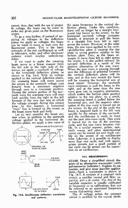
302 sEcoND-u-Ass RADIOTELEPHONE LICENSE HANDBOOK
parent, then, that with the use of proper de voltage, the beam can be made to strike any given point on the fluorescent screen. To go a step further, if instead of ap-
plying dc voltages to the deflection plates we apply ac voltages, the beam can be made to move or scan over the fluorescent screen. This is the basic principle of the test oscillograph as well as television, radar, and other electronic systems which employ cathode-ray tubes.
If we want to make the scanning beam move in a linear manner from the left side to the right side of the screen, we apply a sawtooth of voltage to the horizontal deflection plates, as shown in Fig. 14-6. With no voltage applied to the vertical deflection plates, the scanning beam will move across the screen as the sawtooth voltage rises linearly from a maximum negative through zero to a maximum positive. During the retrace portion of the saw-tooth wave the scanning wave will snap back quickly from the right to the left because of the very fast rate at which the voltage changes during this retrace time. In this manner, a horizontal "trace" line is formed on the screen as the beam scans back and forth.
Let us next consider the beam mo-tion when, in addition to the sawtooth voltage applied to the horizontal de-flection plates, we apply a sine wave of
O SAP/TOOTH APPLIED TO RIGHT PLAIE
'NJ
• RIGHT SIDE RIGHT,
CIPHER
LEFT SIDE
HORIZONTAL LINE TRACED ON SCREEN
O
SINE WAVE TO TOP PLATE
- LEFT
SINE WAVE TRACED OUT ON SCREEN
Fig. 14-6. Oscilloscope deflection waveforms and patterns.
RIGHT
CENTER
the same frequency to the vertical de-flection plates. Under this condition, there will no longer be a straight hori-zontal line traced on the screen. As the horizontal sawtooth voltage increases linearly, it attempts to pull the beam in a straight line from left to right across the screen. However, at the saine time, the sine wave applied to the verti-cal-deflection plate is causing the top plate to swing positive relative to the bottom plate. Thus, as the beam at-tempts to move from left to right across the screen, it is also pulled upward. Its upward deflection is a result of the positive alternation of the sine wave. When the sine wave is passing through zero the difference of potential between the vertical deflection plates will be zero, and at this very instant the beam will be crossing the horizontal axis at dead center. However, the sawtooth wave continues to pull the beam to the right, and at the same time the sine wave goes into its negative alternation, which makes the bottom plate positive relative to the top plate. As a result, the scanning beam is pulled below the horizontal axis, and the negative alter-nation of the sine wave is traced out on the screen. At the end of the cycle the beam is snapped back to the left very quickly by the retrace of the sawtooth, and the oscilloscope is ready to trace out the next sine-wave cycle. This cycle is traced out on top of the previous cycle, and the sine wave becomes visi-ble. In a similar manner, pulses, saw-tooth waves, and other nonsinusoidal waves can be traced out and made visi-ble on the screen of an oscilloscope tube. Likewise, it is possible to display more than one cycle, and with appro-priate circuits just a small portion of one cycle can be spread out for inspec-tion on an oscilloscope.
14-2. MEASUREMENTS
III-248. Draw a simplified circuit dia-gram of an absorption wavemeter (with galvanometer indicator). Explain its op-eration, and give some possible applica-tions.—Such a wavemeter is shown in Fig. 14-7. It consists of a resonant tank circuit, a rectifier crystal and filter ca-pacitor, and a dc meter. The dial of the variable capacitor is usually calibrated in frequency or in calibrations that can be referred to an associated frequency versus dial-setting chart. The rf voltage across the resonant
circuit is rectified by the crystal diode.

ELEMENT III TEST EQUIPMENT, MEASUREMENTS, AND RADIO LAW
Its pulsations are filtered out by the capacitor, causing dc in the de meter. The amount of de varies with the am-plitude of the rf voltage developed in the resonant circuit. The resonant tank circuit is coupled
just close enough to the source of rf energy to provide a meter reading. The capacitor is then tuned for maximum meter reading, indicating that the tank circuit has been tuned to resonance and maximum current is circulating within it. Because maximum current exists when the tank is tuned to the resonant frequency of the rf energy source, the frequency calibration of the capacitor dial corresponds to the frequency of the rf energy source. If the wavemeter is carefully designed and calibrated, and if it is coupled just near enough to the rf source to provide a usable reading, a reasonably accurate frequency measure-ment can be obtained.
Fig. 14-7. Absorption wavemeter.
An absorption wavemeter can be used to determine the presence and frequency of a source of rf energy. It will indicate the frequency made avail-able at the output of a multiplier stage, or the presence of spurious oscillations (self-oscillation or parasitics). It func-tions well as an rf indicator in making resonance, neutralization, and output adjustments.
III-247. Draw a simplified circuit dia-gram of a grid-dip meter. Explain its operation, and give some possible ap-plications.—A grid dip meter is a fre-quency-calibrated oscillator (Fig. 14-8). Plug-in coils are usually employed to provide a wide frequency range. For measurement of grid current, a sensitive de meter is located in the oscillator grid circuit. When the oscillator is in opera-ation, there is a grid-current reading. The grid-dip oscillator can be used
to determine the resonant frequency of a tuned circuit in which there is no rf energy. Thus, one of the advantages of a grid-dip oscillator is that it can be used to measure resonant conditions in a transmitter or other electronic equip-
PLUG-IN COIL
COUPLED NEAR
RESONANT CIRCUIT
TO BE MEASURED
Fig. 14-8. Grid-clip meter.
:303
ment that employs tuned circuits, with-out any power being applied to the unit. When a resonant circuit is coupled
to the grid-dip oscillating tank coil (or associated pickup coil), it absorbs some of the energy from that tank. Inasmuch as energy is removed from the oscilla-tor, the oscillator feedback into the grid circuit decreases. As a result, the grid-current meter reading drops or dips. When the grid-dip oscillator is set on the exact frequency of the resonant cir-cuit under measurement, the meter will dip to its minimum value. This setting indicates that the grid-dip oscillator is generating a signal that is the sanie fre-quency as the resonant frequency of the tuned circuit under check. A grid-dip oscillator can be used to
check resonant circuits throughout a two-way radio transmitter and receiver. It can be used to search for the spurious resonant conditions which cause para-sitic oscillations. Inasmuch as the grid-dip oscillator is itself an oscillator, it can be used as a signal generator for certain tests and measurements, and also for signal tracing.
Most grid-dip meters can also be used as heterodyne-frequency meters because they include a detector and a jack for the insertion of a headset When the frequency of the grid-dip os-cillator and the frequency of a source of signal are brought near to each other, a zero beat is heard in the head-set, and the two frequencies can be matched. A grid-dip meter is also useful in the tuning and matching of antenna sys-tems. Most grid-dip meters can also be operated as absorption wavemeters.
III-248. Draw a block diagram showing only those stages which would illustrate the principle of operation of a second-

304 SECOND-CLASS RADIOTELEPHONE LICENSE HANDBOOK
ary-frequency standard. Explain the functions of each stage.—A secondary-frequency standard serves as a highly accurate frequency calibrator for signal generators and frequency meters. Often it comes as a built-in part of such in-struments, while in other cases it serves as a laboratory standard for calibrating whatever signal generators and fre-quency meters are used. In the United States the primary-frequency standard is maintained by the National Bureau of Standards. Such primary signals are made available through the transmis-sions of station WWV. Thus, a second-ary-frequency standard often includes a receiver for pickup of WWV, or facili-ties for using an external receiver that can be tuned to the WWV signal. A functional arrangement is shown in Fig. 14-9.
FIDE FREQUENCY ADJUSTMENT
00Icliz 10kHz Ikliz
t
.1-1 1/10
I-MHZCRYSTAL
OSCILLATOR
COMMUNICATIONS OR
YAW RECEIVER
1110 1/10
D RIDERS
HARMONIC GENERATOR
HARMONICS AT I-MHz
INTERVALS UP INTO
HUNDREDS OF MEGAHERTZ
Fig 1 4-9. Secondary-frequency standard.
A crystal oscillator is usually em-ployed as the calibrated base-frequency source of the secondary-frequency stan-dard. It operates on one of the WWV frequencies or a subharmonic of one of the frequencies. In the example of Fig. 14-9, a 1-MHz crystal oscillator is being used as a secondary-frequency standard. It can be tuned to precisely 1 MHz by comparing its fifth harmonic to the 5-MHz WWV signal.
Additional accurate frequencies can be obtained by using harmonic genera-tors and frequency dividers after the 1-MHz crystal oscillator. For example, a harmonic generator could supply har-monic checkpoints up into the hun-dreds of megahertz. A series of fre-quency dividers after the oscillator could provide accurate frequency com-ponents at 100 kHz, 10 kHz, and 1 kHz intervals. 111-249. Draw a block diagram of a het-erodyne-frequency meter which would include the following stages: crystal os-cillator, crystal oscillator harmonic am-plifier, variable-frequency oscillator, mixer, detector and af amplifier, and af
modulator. Show rf input, and rf, af, and calibration outputs. Assume a band-switching arrangement, and a dial hav-ing arbitrary units employing a vernier scale. (a) Describe the operation of the meter. (b) Describe, step by step, how the crystal should be checked against WWV, using a suitable receiver. (c) Under what conditions would the af modulator be used? (d) Describe, step by step, how the unknown frequency of a transmitter could be determined by use of headphones or by use of a suit-able receiver. (e) What would be meant by calibration check-points? When should they be used? (f) If in measuring a frequency the tuning dial should show an indication between two dial-frequency relationships in the cali-bration book, how could the frequency value be determined? (g) How could this meter be used as an r-f generator? (h) Under what conditions would it be necessary to recalibrate the crystal os-cillator?—( a) The basic principle of op-eration of the heterodyne-frequency meter involves the beating together of two radio-frequency signals, one whose frequency is known and the other whose frequency is to be determined. When two such frequencies are com-bined in a nonlinear device, such as a mixer, an audio tone is produced when the two frequencies are brought so near to each other that an audible difference frequency is produced. When the two frequencies are brought precisely to-gether, the difference frequency will be zero (zero beat), and no output will be heard. Under this condition, the fre-quency of the signal to be measured matches the frequency calibration of the known-frequency oscillator. A functional block diagram of a typi-
cal heterodyne-frequency meter is shown in Fig. 14-10. It is the variable-frequency oscillator (including band-switching arrangement and vernier dial) which must be kept in accurate calibra-tion. The crystal oscillator and its har-monic amplifier can serve as a second-ary-frequency standard. The fifth har-monic of the 1-MHz crystal oscillator can be checked on the 5-MHz WWV signal. The 1 MHz and higher harmon-ics of the crystal section can then be used to check the variable-frequency (li ai calibrations over its operating range, up into the vhf and uhf range. There will be calibration points at 1-MHz intervals. Of course, it is possible to check the variable-frequency oscilla-tor directly with WWV signals at those

ELEMENT III TEST EQUIPMENT, MEASUREMENTS, AND RADIO LAW 305
RF OUTPUT
î
VARIABLE-FREQUENCY OSCILLATOR
AF MODULATOR
AF INPUT
RF INPUT
MIXER
CRYSTAL OSC. HARMONIC AMPLIFIER
CRYSTAL OSCILLATOR
I-MHz
Ai DETECTOR AND
AF AMPLIFIER
AF OUTPUT
CALIBRATION OUTPUT
Fig. 14-10. Functional plan of a heterodyne-frequency meter.
frequency outputs which correspond to the frequencies of WWV transmissions. The mixer is used to introduce the
harmonic components of the crystal os-cillator in such a manner that a beat note can be heard in the audio output of the heterodyne-frequency meter whenever the variable frequency oscil-lator is set to one of the crystal harmon-ics. The af amplifier is used to build up the level of the beat note or the level of any signal which has been demodulated by the af detector. The heterodyne-frequency meter also
includes an af modulator. Thus an ex-ternal audio-tone signal or other modu-lating waves can be used to modulate the variable-frequency oscillator. The a? detector permits the modulation to be removed from any incoming modulated signal. The signal to be checked is also ap-
plied to the mixer. Here it combines with the variable-frequency oscillator signal or an appropriate harmonic to produce a zero beat which is amplified. The zero beat can be heard by inserting a headset into the a-f output jack. A zero beat indicates that the variable-frequency oscillator has been set to the frequency of the signal to be checked. The calibrated band switch and dial of the frequency meter can then be used to find the exact frequency of the in-coming signal, using an associated cali-bration book.
(b) A 1-MHz crystal is being used in the heterodyne frequency meter of Fig. 14-10. A lead from the calibration output of the heterodyne-frequency me-ter can now be run to the input of a communications receiver that will be used to pick up the WWV signal. Tune the receiver to the 5-MHz WWV signal. Now turn on the 1-MHz crystal oscil-
lator. A beat note will now be heard in the output of the WWV receiver. Ad-just the calibration control of the 1-MHz crystal oscillator until there is an exact zero beat with the WWV signal.
(c) The af modulator can be used to apply modulation to the variable-fre-quency oscillator of the heterodyne-fre-quency meter. It can then be used as a signal generator supplying, when neces-sary, a modulated rf signal for test pur-poses.
(d) The heterodyne-frequency meter is turned on and permitted the pre-scribed warm-up period. An output taken from the transmitter is applied through a suitable attenuator-isolation network to the rf input of the hetero-dyne-frequency meter. The heterodyne-frequency meter is set to the proper frequency band. The calibration on this band can be checked using the appro-priate crystal harmonics. The crystal can now be turned off and the variable-fre-quency oscillator varied in frequency until a zero beat is established with the unknown-frequency signal. This zero beat is heard by plugging the head-phone into the af output jack. A true zero-beat point is indicated when the audio tone begins to rise in frequency when the variable-frequency oscillator is adjusted to either side of the zero beat. A suitable receiver that is tunable to
the transmitter-frequency range can also be used as a beat indicator. In this case, the transmitter signal is picked up on the receiver. Proper precautions must be taken so that the transmitter signal does not overload the receiver. A connection is made between the rf output of the heterodyne-frequency me-ter and the antenna input of the re-ceiver. Loose coupling is usually pre-ferred so as not to overload the receiver. The transmitter signal is tuned in on the receiver. The variable-frequency oscillator of the heterodyne-frequency meter is now set to the proper band, and its frequency is varied until a zero beat is heard in the output of the re-ceiver. This indicates that the transmit-ter and the heterodyne-frequency meter are on the saine freauency. The fre-quency of operation of the transmitter can now be read from the calibration dial of the heterodyne-frequency meter.
(e) When the crystal oscillator is turned on, zero-beats will be heard (headphones plugged into the af output jack) at regular points as the variable-frequency oscillator is tuned over its

306 SECOND-CLASS RADIOTELEPHONE LICENSE HANDBOOK
range. These are known as calibration checkpoints. A beat can be heard at every megahertz point in the example of Fig. 14-10. (It is possible with the addition of suitable circuits to have checkpoints every 100 kHz or even every 10 kHz.) Checkpoints are useful in checking the calibration of the vari-able-frequency oscillator on its various frequency bands. It is particularly help-ful in checking two specific frequency points, one on each side of the variable-oscillator setting, after it has been made to match the frequency of the unknow-frequency signal. By knowing the dial readings for the two frequency check-points and also the dial reading that matches the unknown frequency, an interpolation procedure can be used to more exactly determine the unknown frequency.
(f) If the frequency to be measured falls between two dial-calibration points or between two checkpoints, an inter-polation procedure can be followed. For example, if the dial reads 46 for 32 MHz and 38 for 31 MHz and the dial reading for the unknown frequency is 39.2, the unknown frequency can be found. Assuming a straight line relation between the frequency and dial read-ing, the frequency calibration would be 125 kHz per division [1000 kHz ÷ (46 — 38)]. The unknown frequency to be measured can now be determined as follows:
1. Frequency is 1.2 divisions (39.2 — 38) above 31 MHz.
2. This corresponds to a frequency increase of 150 kHz (1.2 X 125).
3. Unknown frequency is 31.15 MHz (31 -F 0.150).
(g) An rf output is made available by the variable-frequency oscillator. Consequently, the heterodyne-frequency meter can also be used as a calibrated signal source. It can be used for signal tracing or adjustment/alignment of a communications receiver. With a suit-able audio oscillator, it can also be tone-modulated via the af modulator, if a modulated signal source is required to obtain a more accurate zero beat.
With the crystal oscillator turned on, a calibrating signal can also be made available for checking out the frequency calibration of a communications re-ceiver. A modulated audible tone would be heard at each 1-MHz point over the frequency range of the communications receiver.
(h) The crystal-oscillator frequency should be checked on a scheduled basis and before use (after a suitable warm-up period) when very critical frequency measurements are to be made. Of course, the oscillator should be recali-brated whenever a crystal or an oscil-lator tube or transistor replacement is made, or when replacing any compo-nent of the oscillator-multiplier circuits that could influence the crystal-oscillator frequency. Inasmuch as crystals are temperature-sensitive, rather frequent WWV calibration may be necessary when the crystal is not a part of a ther-mostatically controlled oven.
111-250. Draw a block diagram of an fm deviation (modulation) meter which would include the following stages: mixer, i-f amplifier, limiter, discrimina-tor, and peak-reading indicator. Explain the operation of this instrument, and draw a circuit diagram and explain how the discriminator would be sensitive to frequency changes rather than to ampli-tude changes.—A functional block dia-gram is shown in Fig. 14-11. The typi-cal fm deviation (modulation) meter is comparable to a high-quality fm re-ceiver. The fm signal, modulated by a test signal, is applied to the mixer through a suitable isolation-attenuator arrangement. The modulation meter in-cludes a local oscillator, and the mixer output is tuned to the difference i-f fre-quency. The i-f signal component is in-creased in amplitude and then applied to a limiter which removes any ampli-tude variations. The i-f output of the limiter is applied to the fm discrimina-tor. The audio test modulation of the fm
signal is recovered at the output of the fm discriminator. To determine the peak deviation of the fm signal, it is neces-sary to develop a de component of volt-age which corresponds to the peak am-plitude of the demodulated audio sig-
SIGNAL TO BE •
MEASURED MIXER
CALIBRATED LOCAL-
OSCILLATOR SOURCE
AMPLIFIER LIMITER
DISCRIMINATOR
PEAK-READING INDICATOR
Fig. 14-11. Functional plan of an fm devia-tion meter.

ELEMENT III TEST EQUIPMENT, MEASUREMENTS, AND RADIO LAW 307
FROM I-F AMP
FM MODULATING I-F SIGNAL WAVE OUTPUT
PEAK RECTIFIER
DC CHARGE SET BY MAXIMUM DEVIATION
Fig. 14-12. An fm discriminator and peak voltmeter.
nal. This is accomplished by means of a peak rectifier. This dc component is then applied to a balanced vtvm stage and its associated sensitive current me-ter which is calibrated in terms of fre-quency deviation. A simplified circuit diagram of a dis-
criminator and peak voltmeter is given in Fig. 14-12. The output of the dis-criminator is a function of the applied frequency change. The limiter stages previous to the discriminator have re-moved any existing amplitude varia-tions. Thus, amplitude changes which may have been present as a result of noise or interference are not able to contribute to any variations at the out-put of the discriminator. The discrimi-nator responds to the phase relationship among the three voltages, E,, E2, and E3. These phase changes are brought about by any frequency deviation of the incoming signal. The process of con-verting the phase changes to amplitude variations at the output of the discrimi-nator were covered in detail in the dis-cussion associated with Figs. 12-10 and 12-12. As mentioned previously, the circuit
must be made to respond to the peak amplitude of the demodulated audio variation. To do this, the output of the discriminator is fed through an isolation stage to a diode peak rectifier. The in-put time constant of the peak rectifier is such that when the rectifier conducts, the output capacitor charges to the peak amplitude of the demodulated wave. The long output time-constant keeps the dc charge steady between peaks, and a de voltage is applied to the grid of the vtvm tube. As the peak amplitude of the modulating wave changes, so also does the peak charge placed on capaci-tor Cl change. It should be stressed that the output of the discriminator varies in amplitude in accordance with the fm deviation. The greater the deviation of the applied signal, the higher is the
CALIBRATED METER
peak amplitude of the demodulated wave at the output of the discriminator.
111-251. Why is it important that a transmitter remain on frequency, and that the harmonics be attenuated?—lt is important that transmitters remain on frequency because of the multiple use of the radio spectrum and, in the case of two-way radiocommunications, be-cause of the use of crystal-controlled receivers which are preset to the trans-mit frequency. In the latter case, dis-tortion and poor performance would re-sult if the transmitter frequency would drift and be incorrect in relation to the crystal-controlled receiver frequency. Radio channels are allocated very near to each other, and a transmitter-fre-quency drift can cause interference with stations that are operating on adjacent channels.
Likewise, harmonic output is to be avoided because these harmonics may fall on the assigned frequencies of sta-tions which operate on higher-frequency bands. Even very weak harmonic com-ponents can cause havoc in nearby re-ceivers which must pick up a signal from a very distant station operating on the saine frequency.
111-252. Describe a usual method (and equipment used) for measuring the har-monic attenuation of a transmitter.—A field-strength meter, in the arrangement of Fig. 14-13, is best used to measure the level of harmonic components. A field-strength meter is a combination receiver and calibrated signal-strength meter. To measure harmonics properly it is necessary to use certain band-elimination and bandpass filters. In a harmonic measurement, the elimination filter is used to tune out the carrier, pre-venting it from overloading the field-strength meter. The bandpass filter is critically tuned to the frequency to be measured, therefore it permits only the

308 SECOND-CLASS RADIOTELEPHONE LICENSE HANDBOOK
desired harmonic component to enter and produce a field-strength reading.
In such an arrangement it is possible to measure exactly the level of unde-sired harmonics. Furthermore these lev-els can be measured with relation to the strength of the fundamental carrier. Consequently, it is possible to obtain a decibel-comparison figure, making it appropriate for the manner in which the FCC specifies the required harmonic attenuation.
14-3. RULES AND REGULATIONS
Second-class radiotelephone operators should be familiar with various parts of the Commission's Rules and Regula-tions, especially those sections of the Rules listed below:
Part 2: General Rules and Regulations
Sec. 2.1. Definitions: (Refer to Ap-pendix II). Authorized frequency. Carrier. Base station. Coast station. Earth station. Fixed station. Space station. Harmful interference. Land Mobile Service. Land station. Mobile service. Primary standard of frequency.
Sec. 2.101. Nomenclature of frequen-cies (Refer to Appendix V).
Sec. 2.201. Emission, modulation, and transmission characteristics (subparts a, b, c, and d only).
Sec. 2.551. Program defined. Part 89. Public Safety Radio Services
(Refer to Appendix V). Sec. 89.3. Definitions.
Authorized bandwidth. Bandwidth occupied by an emission. Station authorization.
ANTENNA
Sec. 89.51. Station authorization re-quired.
Sec. 89.53. Procedure for obtaining a radio-station authorization and for com-mencement of operation.
Sec. 89.55. Filing of applications. Sec. 89.57. Who may sign applica-
tions. Sec. 89.59. Standard forms to be
used. Sec. 89.75. Changes in authorized
station. Sec. 89.103. Frequency stability. Sec. 89.107. Emission limitations. Sec. 89.109. Modulation require-
ments. Sec. 89.113. Transmitter control re-
quirements. Sec. 89.115. Transmitter measure-
ments. Sec. 89.117. Acceptability of trans-
mitter for licensing. Sec. 89.153. Station identification. Sec. 89.175. Contents of station rec-
ords. Sec. 89.177. Form of station records.
III-253. Define the words and phrases listed under Sec. 2.1 of the Commis-sion's Rules.—Refer to the appropriate definitions in Appendix II.
III-254. Give the frequency ranges as-sociated with the following general-fre-quency subdivisions: (a) vif, (b) If, (c) mf, (d) hf, (e) vhf, (f) uhf, (g) shf, (h) ehf.— ( a) Below 30 kHz. (b) 30 to 300 kHz (c) 300 to 3000 kHz (d) 3000 to 30,000 kHz (e) 30,000 kHz to 300 MHz (f) 300 to 3000 MHz (g) 3000 to 30,000 MHz (h) 30,000 to 300,000 MHz
III-255. What is meant by the following emission designations? ( a) A3, (b)
FIELD-STRENGTH ME111(
TUNABLE INPUT SYSTEM
FILTERS RECEIVER AMPLIFIER
CALIBRATED F IELD-STRENGTH
INDICATOR
Fig. 14-13. Field-strength meter arrangement for measuring harmonics.

ELEMENT III TEST EQUIPMENT, MEASUREMENTS, AND RADIO LAW 309
A3A, (c) A5C, (d) F3, (e) F5, (f) P3I). — (a) A3 emission is conven-tional amplitude-modulated radiotele-phony with double sideband and full carrier. ( b ) A3A transmission is a-m radio-
telephony with single sideband and re-duced carrier. This means that some carrier is present, but is of a low value.
(e) A5C emission refers to ampli-tude-modulated television transmission using vestigial-sideband emission.
(d) F3 is frequency- (or phase-) modulated telephony transmission.
(e) F5 is television transmission us-ing frequency (or phase) modulation.
(f) P3D emission is a form of pulse-modulated radiotelephony using ampli-tude-modulated pulses.
Refer to RR 2.201.
111-256. What is the basic difference between type approval and type accept-ance of transmitting equipment?—Type approval of equipment contemplates tests conducted by the FCC commission personnel, while type acceptance is based on data concerning the equip-ment submitted by the manufacturer or the individual prospective licensee. Re-fer to RR 2.551 and 89.117.
III-257. Define the words and phrases listed previously under Sec. 89.3 of the Commission Rules.—Refer to the appro-priate definitions in Sec. 89.3 of Appen-dix V.
III-258. May stations in the Public Safety Radio Services be operated for short periods of time without a station authorization issued by the Commis-sion?—No. There is one possible excep-tion. Such a station may be so operated under appropriate conditions between the time that the formal application is made to the FCC after testing, and pending Commission action on the li-cense application. (Refer to RR 89.51 and 89.53.)
III-259. What notification must be for-warded to the engineer in charge of the Commission's District Office prior to testing in the Public Safety Radio Serv-ice a new radio transmitter which has been obtained under a construction per-mit issued by the Commission?—Such notification must be made in writing at least two days in advance of the test date. FCC Form 456 may be used for this purpose. The notification tells the engineer in charge when the transmitter
in question will first be tested in such a manner as to produce radiation, and it also gives the name of the permittee, station location, call sign, and frequen-cies on which tests are to be conducted. (Refer to RR 89.53).
111-260. Where may standard forms ap-plicable to the Public Safety Services be obtained?—Standard forms may be obtained from the FCC, Washington, D.C., 20554, or its engineering field of-fices. ( Refer to RR 89.55.)
III-261. In general, what type of changes in authorized stations must be approved by the Commission? What type does not require Commission ap-proval?—Changes that require approval are those that will result in operation inconsistent with any of the terms of the current authorization. Those changes which will not depart from any of the terms of the outstanding authorization may be made without prior Commission approval. Included in such changes would be the substitution of various makes of transmitting equipment at any station, provided the particular equip-ment is in the FCC list of acceptable equipment for licensing, employs the same type of emission, and does not ex-ceed the power limitations as set forth in the station authorization. (Refer to RR 89.75).
111-262. The carrier frequency of a transmitter in the Public Safety Radio Service must be maintained within what percentage of the licensed value? Assume that the station is operating at 160 MHz with a license power of 50 watts.—The carrier-frequency percent-age tolerance is 0.0005 percent (Refer to RR 89.103.)
111-263. What is the authorized band-width and frequency deviation of a Pub-lic Safety station operating at 30 MHz? At 160 MHz?—Bandwidth and fre-quency deviation at 30 MHz is 20 kHz and -175 kHz, respectively. At 160 MHz it is also 20 kHz bandwidth, and ±-5-kHz deviation. (Refer to RR 89.107.)
III-264. What is the maximum percent-age of modulation allowed by the Com-mission's rules for stations in the Public Safety Radio Services which utilize amplitude modulation?—It shall be suf-ficient to provide efficient communica-tion and normally be maintained above 70% on peaks, but it shall not exceed

310 SECOND-CLASS RADIOTELEPHONE LICENSE HANDBOOK
100% on negative peaks. (Refer to RR 89.109.)
111-265. Define control point as the term refers to transmitters in the Public Safety Radio Service.—A control point is an operating position which meets the following conditions: (1) The position must be under the control and supervi-sion of the licensee. (2) It is the posi-tion at which the monitoring facilities are employed. (3) It is the position at which the person immediately respon-sible for the operation of the transmit-ter is stationed. (Refer to RR 89.113.)
III-266. Outline the transmitter mea-surements required by the Commis-sion's rules for stations in the Public Safety Radio Service.—The required transmitter measurements are carrier frequency, input power to the final rf stage, and the degree of modulation. Such measurements should be made when the transmitter is initially in-stalled, when any change is made in the transmitter which may affect any one of these requirements, and at intervals not to exceed one year. For transmitters employing crystal-controlled oscillators, frequency should be checked at inter-vals not to exceed one year; and at in-tervals not to exceed one month for transmitters not employing crystal-con-trolled oscillators. Power input is the product of the
plate-supply voltage and the de compo-nent of plate current applied to the final radio-frequency stage. (Refer to RR 89.115.)
111-267. What are the general require-ments for transmitting the identification announcements for stations in the Pub-lic Safety Radio Service?—Assigned call signals or approved identifiers must be transmitted at the end of each transmis-sion or exchange of transmissions, or once each 30 minutes of the operating period, as the licensee may prefer. If a mobile station, authorized to the li-censee of an associated base station, transmits only on the base-station trans-mit frequency, identification is not re-quired. (Refer to RR 89.153.)
111-268. When a radio operator makes transmitter measurements required by the Commission's rules for a station in the Public Safety Radio Services, what information should be transcribed into the station's records?—The measure-ments must be made by a first- or sec-
ond-class radiotelephone or radiotele-graph operator or by an engineering service employing such qualified opera-tors. The appropriate measurements, date, and signature of person making the measurements service shall be re-corded in the station's records. Included in the records should be license class, serial number, and expiration date. ( Re-fer to RR 89.115 and 89.175.)
111-269. What are the Commission's general requirements regarding the rec-ords to be kept by stations in the Pub-lic Safety Radio Service?—Such records shall include the results and date of re-quired transmitter measurements, and the name of the person or persons mak-ing such measurements. Information should be included in the records re-garding the details of all duties per-formed by the responsible operator, and it shall include his naine and address, as well as the class, serial number, and expiration date of his license. The station records shall also include
the name or names of persons responsi-ble for the operation of the transmitting equipment each day, together with the periods of their duty. Additional infor-mation must be recorded when the an-tenna or supporting structure is required to be illuminated. Station records must be kept for a period of at least one year. (Refer to RR 89.175 and 89.177.)
14-4. SCHEMATIC QUESTIONS
There are a number of questions in-volving schematic completion and iden-tifying mistakes or omissions on sche-matics. Information may be asked about a specific part of a schematic. It is im-portant then to refer to the various sche-matics given in the study guide chap-ters. Refresh your memory regarding the function of various parts and try to an-ticipate how a specific part failure may have an adverse influence on an associ-ated stage. Several basic vacuum-tube circuits will be reviewed in the follow-ing paragraphs to aid in your schematic studies. Parts functions and the influ-ence of part failures are emphasized. Component values are given in the rep-resentative circuits so they might be built up and checked out if you so desire.
14-4-1. Audio-Frequency Amplifiers A triode grounded-cathode amplifier
is shown in Fig. 14-14. By using the component values shown, a voltage gain

ELEMENT III TEST EQUIPMENT, MEASUREMENTS, AND RADIO LAW
AUDIO GEN 1000-
OC VTVM C3
(-4.- OSCILLOSCOPE 0.0IuF
100K
4 R4 100K
Fig. 14-14. Grounded-cathode amplifier.
of approximately 50 can be obtained. That is, an input signal of one-half volt will result in a 25-volt output signal. The functions of the individual parts are:
Cl. Coupling capacitor that provides de isolation between input circuit and signal source.
RI. Grid resistor. The signal voltage is developed across this resistor. A sec-ondary function of the resistor is to pre-sent a discharge patn for electrons that accumulate on the control grid.
R2. Cathode resistor. The presence of plate current in this resistor develops a positive dc voltage between cathode and ground, thus developing the grid bias. The dc bias voltage acting be-tween grid and cathode is negative.
C2. Cathode bypass filter capacitor. This capacitor prevents ac degenera-tion. If its filtering action were not pres-ent, an ac voltage would also develop across resistor R2 as a result of the changes in plate current with signal. The phase of such an ac voltage would be opposite to the phase of the grid sig-nal and would subtract from the grid signal. It would reduce the effective grid signal and lower the overall gain of the stage.
R3. Plate load or plate coupling re-sistor. With applied signal, the changing plate current in this resistor causes a change in the plate voltage. The plate-voltage change is the useful output of the amplifier.
C3. Coupling capacitor. The coupling capacitor again isolates the dc of one stage from that of the next stage. How-ever, such a capacitor offers a minimum reactance to the ac voltage change and, therefore, the ac output at the stage is coupled to the next stage.
R4. This is a decoupling resistor. It isolates the ac variations of a given
9 5
I2V FIL 6V FIL
311
stage from the power supply imped-ance. It also blocks any ac variation that might appear across the power supply from the sensitive input stages of an audio amplifier. Often another func-tion of a decoupling resistor is to lower the dc voltage of the supply line to the value required by a given vacuum-tube stage.
C4. This is a decoupling capacitor. Filtering requires the joint influence of both resistor and capacitor (R4-C4) in smoothing out undesired ac variations. It is the combination that does the fil-tering and makes available a steady de voltage for the individual stage.
Next consider each individual part in terms of the trouble it might cause in a circuit if it became defective. The two extremes, open or shorted, are used. It is understood that similar defects, al-though not as severe, can be introduced when the component value changes. In general, it introduces the same sort of defect but the degree of influence will not be as great. In considering the ac signal performance of the stage, assume that the applied signal level approxi-mates the desired maximum signal level of operation for the stage. Cl shorted. If the source of signal
also contains a de component, this de voltage is transferred to the grid and can cause improper biasing conditions. Cl open. This results in no applied
signal. The de operating conditions of the stage are unchanged. RI open. The influence of the open
grid resistor depends to a great extent on the circuit arrangement and the par-ticular tube type. In some arrangements electrons accumulate on the control grid to such an extent that the tube is cut off. In other circuit arrangements, when too high a value grid resistor is used, a grid gas current could occur to

312 SECOND-CLASS RADIOTELEPHONE LICENSE HANDBOOK
bias the grid in the positive direction which would result in excessive de cur-rents in the tube. RI shorted. No ac input or no output
because the applied signal is shorted between grid and ground. C2 open. Ac degeneration results and
there is less output signal for a given input signal. De operating conditions do not change. C2 shorted. Stage is now improperly
biased and the output may become dis-torted. There is a drop in the de plate voltage and a rise in the de plate cur-rent because of the bias removal. R2 shorted. Same defect as that
which occurs when capacitor C2 is shorted. R2 open. Tube is cut off and becomes
inoperative. There is no ac output, plate current is zero, and plate voltage is maximum. R3 open. This defect is similar to the
conditions that exist when R2 is open. The tube is cut off, there is no output and the plate current is zero. In this case the plate voltage is also zero. How-ever there will be maximum supply voltage at the junction of capacitor C4 and resistor R4. R3 shorted. There is no ac output
voltage. The de plate current is higher and so is the de plate voltage. C3 open. No ac signal voltage is
transferred to the succeeding stage. C4 open. Output voltage may rise be-
cause of the increase in the effective ac load resistance with the removal of the decoupling circuit and the addition of resistor R4 to the load. Output voltage may be distorted because of the non-linear operating conditions. If the stage were associated with an amplifier chain, there would be a danger of self-oscil-lation, motorboating, or other distur-bances that arise from improper de-coupling. C4 shorted. When C4 is shorted there
is no supply voltage applied to the stage. Output is zero, plate current is zero, and plate voltage is zero. In many circuits there could be excessive current in the decoupling resistor R4 and it would overheat. R4 open. The supply voltage would
again be removed from the stage. Out-put voltage, plate current, and plate voltage would all be zero. R4 shorted. Supply voltage increases
as do the dc plate current and de plate voltage. Output voltage may increase slightly. Again, if the stage were asso-ciated with a multistage amplifier, low-
frequency feedback disturbances could arise. A pentode grounded-cathode ampli-
fier is shown in Fig. 14-15. Except that a screen-grid tube is used, note its sim-ilarity to the circuit of Fig. 14-14. A major advantage of the pentode stage, in addition to the better isolation be-tween output and input, is the fact that the plate voltage has much less of an influence on the plate current. The screen grid takes over in the control of electron flow between cathode and plate. As a result the pentode has a greater voltage-amplification capability. That is to say, an output voltage of a given magnitude can be obtained with a much lower input voltage in compari-son to a comparable triode circuit. The circuit is itself identical to that of a tri-ode with the exception that a screen re-sistor R5 and a screen capacitor C5 are required. An input signal of one-half volt will result in a 40-volt output for the circuit of Fig. 14-15. The function of screen resistor R5 is
to reduce the supply voltage to a value appropriate for the desired operating conditions. The screen capacitor C5 is a bypass or filter capacitor. It prevents degeneration in the screen-grid circuit. It does so by preventing the variations in the screen-grid current from causing a change in the screen-grid voltage. It holds the screen-grid voltage constant in the same manner that the cathode filter capacitor holds the cathode bias con-stant. The remainder of the components of the stage have functions identical to their like components in the triode cir-cuit in Fig. 14-14.
Except for the screen resistor and screen capacitor combination, compo-
CI
a
RI
6UAA
CS 84F
•300
C3
C4 810
IC0(
EBB
Fig. 14-15. Pentode grounded-cathode am-plifier circuit.

ELEMENT III TEST EQUIPMENT, MEASUREMENTS, AND RADIO LAW 313
nent defects produce the same faults as those covered in conjunction with Fig. 14-14. If screen-grid resistor R5 opens there is no screen-grid voltage and the stage reverts to triode operation. The output voltage is low and distorted. There is also a change in the de operat-ing conditions, plate current falls, and plate voltage rises. If resistor R5 were to short, there would be a higher than normal screen grid voltage. The screen and plate currents would rise and there could be excessive screen-grid and/or plate dissipation.
If the screen-grid capacitor were to open, the screen-grid voltage would also vary with the applied signal. The stage would become degenerative and there would be a reduction in the out-put voltage. A shorted screen-grid ca-pacitor would also remove the screen-grid voltage and the same circuit faults would develop that result when the screen-resistor is open.
In troubleshooting one should always remember that a shorted capacitor, more than likely, wil also result in an overheated resistor. Thus what often appears to be a resistor defect is in fact being caused by a shorted or leaky ca-pacitor. Thus, in the above example the shorted capacitor mien also cause an overheated screen-grid resistor. A single-tube phase splitter is shown
in Fig. 14-16. Such a stage provides a means of obtaining opposite-polarity and nearly equal-amp!itude output sig-nals for driving the input of a push-pull stage. One output is removed across
Cl
O. 010F
RI
EBB
• 300/
R3 100K
C3
12A X7 (--•" 2 0.0Ie
C4
(-4".
RO 100( 0. Ole
Fig. 14-16. Single-tube phase splitter.
resistor R3; the other output is taken across resistor R4. Inasmuch as the stage has both plate and cathode outputs, it functions in part as a cathode-follower and, therefore, the gain is very low. For example with a 5-volt input signal there is approximately 4.9 volts output at the plate. Considering the two outputs as being connected in series, there would be a net overall gain approaching 2. It is most important to recognize that the two output voltages are of opposite po-larity and almost equal in amplitude. The functions of the parts are: Cl. Coupling capacitor. Function is
the same as capacitor Cl of Fig. 14-14. RI. Grid resistor. Function is the
same as resistor RI of Fig. 14-14. Note that the low end of resistor RI is con-nected to the junction of resistors R2 and R4. This connection makes certain that the grid-cathode bias equals the dc charge placed on capacitor C2.
R2. Cathode bias resistor. The de plate current in this resistor develops the de bias voltage for the stage.
C2. The cathode bypass filter capaci-tor. The dc charge on this capacitor is the bias for the stage.
R3. Plate load resistor. The ac plate-current variation in this resistor devel-ops the output voltage change at the plate of the tube.
C3. Coupling capacitor. It has the same function as C3 of Fig. 14-14.
C4. Also a coupling capacitor for the opposite polarity output of the stage.
R4. This is the cathode output re-sistor. The cathode-current variation (same as plate-current variation) in this resistor develops the ac output voltage that is made available in the cathode circuit. The ac voltage across this resis-tor is less than the applied ac voltage because it is a cathode-circuit load. A similar but opposite polarity voltage is made available at the plate. The influence of component faults
are as follows: Cl open. Loss of grid signal. Cl shorted. Possible change in oper-
ating conditions through the exchange of dc components. In this case the high de voltage across R4 is transferred to the preceding stage or signal source. RI open. This open resistor results in
an improper bias which causes a fall in the dc plate current and a rise in the de plate voltage. Under certain circum-stances, a distorted ac output also oc-curs. RI shorted. There is a reduction in
the magnitude of the output signal that

314 SECOND-CLASS RADIOTELEPHONE LICENSE HANDBOOK
is made available by the basic design. The input signal is in effect applied across resistor R4. R2 open. Circuit becomes inoperative
because of the interruption of the dc current path. Plate current is zero and the plate voltage high. R2 shorted. No bias is applied to the
stage and improper operating conditions are established. There could be some distortion of the output voltage. Plate voltage falls and plate current rises. C2 shorted. Same effects as R2
shorted. C2 open. The influence would be lim-
ited although there would be some ad-ditional inequality in the output magni-tudes. R3 shorted. The plate voltage and
plate current both increase. The stage itself reverts to a cathode-follower with no output made available at the plate. R3 open. The stage becomes inopera-
tive because of the interruption of the de current path. The plate current and the plate voltage both fall to zero. C3 open. No transfer of ac signal to
next stage. C3 shorted. Undesired exchange of
de components between stages. C4 shorted. Likewise, an undesired
exchange of de components between stages. C4 open. No transfer of ac signal to
next stage. R4 open. Stage becomes inoperative
because of the interruption of the de current path. Plate current is zero and plate voltage is maximum.
14-4-2. Oscillators
Two basic oscillator types are cov-ered. Each of the circuits can be con-structed using the low-cost components
C2
+300
EBB
14-17 Tuned-plate tuned-grid oscillator.
STANCOR RTC-8738
Fig
indicated. The first circuit, Fig. 14-17, is a tuned-plate, tuned-grid (tptg) oscillator. Feedback is by way of the interelectrode capacitance in a tptg oscillator. In the oscillating state, the grid current (1.) reads between 0.5 and 1.0 milliampere and the plate current (Ib) reads between 6 and 8.5 milliam-peres. Functions of the parts are as fol-lows:
Li. Coil of the grid resonant circuit. Cl. Capacitor of the grid resonant
circuit. C2. Capacitor of the grid RC combi-
nation. RI. Resistor of the grid-leak RC com-
bination. It is this RC combination that establishes the class-C grid bias for the oscillator. MI. De grid-current meter ( vom or
low current 0 to 1.2 milliammeter). C3. Dceoupling filter capacitor. R2. Voltage-dropping resistor and
part of the RC plate decoupling filter. C4. Capacitor of plate tuned circuit. L2. Inductor of the plate resonant
circuit. L3. Low-impedance secondary coil
associated with the plate resonant cir-cuit.
R3. Oscillator output load resistor. M2. De plate-current meter (von' or
0-25 milliammeter ). Component failures will affect the
oscillator operation in the operation in the following manner: Li open. Oscillations will stop, MI
reading will fall to zero, and M2 read-ing will increase.
Cl shorted. Sanie as Li open. There may be some small contact-potential current read by MI.
Li shorted. Sanie as Li open. Cl open. Same as Li open.
STANCOR OSCILLATOR TRANSFORMER RTC-8738
1
I. -M2
C3 I 1000pF
SCOPE

ELEMENT III TEST EQUIPMENT, MEASUREMENTS, AND RADIO LAW 315
C2 open. Same as Li open (no cut-off grid bias is developed). RI shorted. Oscillations cease, M2
reading rises, and there is some small MI contact current. RI open. Oscillations cease, MI grid
current falls to zero, and M2 plate cur-rent declines. Plate-current drop is a re-sult of the negative charge that grid electrons build up on capacitor C2. C3 open. Oscillations cease because
rf return path is interrupted. MI read-ing to zero and M2 reading increases. C3 shorted. Oscillations cease and
MI current falls to zero. Plate voltage and plate current of the oscillator also fall to zero. However, in the particular circuit arrangement of Fig. 14-17, there will be a high M2 current reading be-cause of the position of the capacitor between the plate side of the meter and ground. An excessive current goes through resistor R2 and it will overheat. R2 open. The oscillator stage be-
comes inoperative. There are no oscil-lations and both meter readings fall to zero. R2 shorted. There is an increase in
supply voltage. Oscillator output in-creases and both meter readings rise. C4 open. Oscillations stop or decline
in level in operating as a different mode oscillator. Plate current rises and grid current declines. C4 shorted. Oscillations cease, grid
current falls to zero, and plate current increases. L2 shorted. Same as C4 shorted. L2 open. Stage becomes inoperative
because of the interruption of the sup-ply voltage. Oscillations cease and both current meters read zero. R3 open. The load is removed from
the oscillator and the plate-current reading declines. There will also be an
Cl
RI
6U8A
9
100K r2vy
increase in the MI meter reading be-cause of an increase in feedback into the grid circuit when the load is re-moved from the plate circuit. R3 shorted. A somewhat greater load
is placed on the oscillator and the plate-current reading will rise. A crystal oscillator is shown in Fig.
14-18. This oscillator is similar to a tptg type, with the crystal acting as the grid resonant circuit. The cathode and plate currents are one and the same, and therefore the plate current can be measured with a meter inserted in the cathode circuit. A popular metering method is shown
in Fig. 14-18. A low-value cathode re-sistor is used and the oscillator-circuit operation will remain essentially the same whether the meter is in or out of the circuit. This technique is adaptable to meter-switching arrangements be-cause the meter can be switched in and out of the cathode circuit and among other circuits of the transmitters at will without affecting operation. The func-tions of the parts are as follows:
Cl. Capacitor of grid RC combina-tion. In some crystal circuit this ca-pacitor is not used because the crystal and its holder can provide the capaci-tance of the grid RC combination.
RI. Resistor of grid RC combination. R2. Metering resistor. C2. Metering circuit bypass. C3. Decoupling rf filter capacitor. R3. Decoupling resistor and plate
voltage-dropping resistor. C4. Capacitor of plate tank circuit. LI. Inductor of plate tank circuit. L2. Low-impedance secondary coil. R4. Output load of the oscillator. It is important to know the tuning
characteristics of a crystal oscillator. The plate current rises when the crystal
100 1-2MHz R2 C2
1VV 500 pF I K
STANCOR RTC-8738
2
C4 Li SCOPE
3
R3
C3 T 1000 pF
4r
15K 2W
+300 EBB
Fig. 14-18. Crystal oscillator.

316 SECOND-CLASS RADIOTELEPHONE LICENSE HANDBOOK
stops oscillating or other defects de-velop. Likewise, detuning capacitor C4 from crystal resonance stops oscillations and causes a plate current rise. As the plate-tank capacitor is tuned to reso-nance, oscillations are indicated by a clip in the plate-current meter reading. The oscillator kicks out of resonance very quickly when the tank is tuned to the low side of the crystal frequency. Oscillations fall off more slowly when capacitor C4 is tuned to the high-fre-quency side of resonance. For best cir-cuit stability it is customary to tune tank-circuit capacitor C4 slightly to the minimum-capacitance ( high-frequency ) side of maximum plate-current clip. Component faults will have the fol-
lowing influence on stage operation: Cl open. Oscillations cease, rf output
falls to zero, and plate current rises. CI shorted. There will be no great
change in operation because the crystal capacitance takes over. RI open. The rf output drops as does
the de plate current. RI shorted. No oscillations, no rf out-
put, and plate current rises. R2 or C2 shorted. No change in cir-
cuit conditions. However, metering cir-cuit will not function.
112 open. Stage becomes inoperative because of the breaking of the de path to the supply line. There will be no oscillations and the plate current will fall to zero. C2 open. No significant change in
circuit operation except perhaps some slight detuning. C4 or Li shorted. No oscillations, no
output, and plate current rises. C4 open. No oscillations, no output,
plate current rises. Li open. Circuit becomes inoperative
because of the interruption of the sup-ply voltage. There will be no oscilla-tions, no output, and the plate current falls to zero. R3 shorted. There is a somewhat
greater output as well as a higher plate current. When the supply voltage is too high and/or the feedback current too great, the crystal can be fractured. R3 open. Circuit again becomes in-
operative because of the interruption of the supply voltage. There will be no oscillations and the plate current will fall to zero. C3 open. No oscillations because of
the interruption of the rf path. The plate-current meter reading rises. C3 shorted. The stage becomes in-
operative because of the removal of the
plate voltage. However the current drawn through R3 can be excessive and the resistor overheats. R4 shorted. A heavier load will be
placed on the oscillator output and the plate-current meter reading rises. Too severe a load on a crystal stage may cause the circuit to stop oscillating completely. R4 open. A very light load will be
placed on the oscillator and the clip in the plate current will be very decided. Output voltage as displayed on the os-cilloscope will increase because of the lighter load.
14-4-3. Basic A-M Transmitter Circuits A basic, simple, and low-cost a-m
transmitter circuit is shown in Fig. 14-19. Such a unit can be assembled readily on a pegboard. The rf circuit consists of a triode Pierce crystal oscil-lator and follow-up class-C amplifier. The audio section consists of a triode voltage amplifier and a pentode class-A modulator. Only three receiving-type tubes are used. The arrangements can be used to verify the operation of basic transmitter circuits and to note the re-sults of component failures. Such an ex-perimental project will firm your knowl-edge of basic vacuum-type transmitter circuits. The functions of the parts are as fol-
lows: X 1. Crystal. Any crystal in the 1- to
2-MHz range can be used. Cl. De blocking capacitor that keeps
the de plate voltage from the crystal. It is also a part of the grid RC combi-nation.
RI. Resistor of grid RC combination. C2. Capacitor that provides easier
starting and a more favorable feedback division for the Pierce crystal oscillator.
R2. Plate-load resistor of the Pierce crystal oscillator.
R3. Metering resistor. C3. Interstage coupling capacitor and
capacitance of grid RC combination. R4. Resistor of grid bias RC combi-
nation for the class-C amplifier. R5. Metering resistor. C4. Screen-grid rf bypass capacitor. 116. Screen-grid voltage-dropping re-
sistor. C5. Rf plate-circuit filter capacitor.
It is made high enough in value that it also filters out the high audio frequen-cies above 3000 Hz.
C6-Li. Plate tank circuit. R7. Metering resistor. Bi. No. 46 pilot-bulb load.

Fig. 1419. An am transmitter.
318 SECOND-CLASS RADIOTELEPHONE LICENSE HANDBOOK
Cl. Input coupling capacitor of the audio amplifier.
R8. Grid resistor. R9. Cathode-bias resistor. C8. Cathode-filter capacitor. RIO. Plate-load resistor of the voltage
amplifier. C9. Interstage coupling capacitor. Pl. Audio gain control. R 1 I. Cathode-bias resistor. C10. Cathode-filter capacitor. C11. Decoupling and audio filter ca-
pacitor. R12. Voltage dropping and decou-
pling resistor. R13. Isolation resistor for supplying
signal from an audio generator. C12. Ftf filter capacitor. Ti. Transceiver modulation trans-
former. This is a popular type of trans-former that permits the same trans-former to be used as the modulation transformer for transmit (primary auto-transformer connection) and an audio output transformer for receive ( low-impedance secondary for speaker). The rf section of the transmitter has
only a single control; this is the plate tonic capacitor of the class-C amplifier. At resonance there will be dip in plate current. The capacitor is adjusted for maximum glow of the bulb. The rf waveform can be observed by connect-ing an oscilloscope probe across the output. The audio generator can now be con-
nected to the transmitter and the gain control advanced until the modulation envelope appears. Almost 100% modu-lation can be obtained. The modulating-frequency range extends from several hundred hertz up to 3000 or 4000 Hz. The effects of rf excitation loss on an
a-m transmitter can be checked by re-moving the crystal from its holder. Both the oscillator and rf amplifier plate cur-rents rise. The grid current falls to zero and there is no rf output. The influence of modulation on the
plate current and output can also be observed. The plate current of the class-C amplifier remains essentially constant as the percentage of modulation is in-creased slowly. The bulb also increases in brightness, indicating that with mod-ulation more power is being delivered to the load. In effect the pilot bulb is functioning as an rf antenna meter which normally reads higher with mod-ulation. At percentages near 100% the modulation becomes nonlinear and there is a slight drop in the plate-cur-rent reading (negative carrier shift).
Component failures influence circuit operation in the following manner: X1 inoperative. Crystal stopping re-
sults in no output and no class-C am-plifier grid current. Both dc plate cur-rents rise. RI shorted. Oscillations stop, produc-
ing the same events as above. CI open. Same as above. Cl shorted. No significant change. C2 open. Oscillator is sluggish in
starting. C2 shorted. Oscillations stop and
crystal-stage plate current rises. Class-C amplifier grid current falls, class-C plate current increases, and there is no rf output. R2 shorted. Oscillations stop and a
high plate current is drawn by the os-cillator tube. Grid current falls to zero for the class-C stage, and its plate cur-rent increases. There is no rf output. R2 open. Oscillator stage becomes in-
operative. Grid current falls to zero and class-C plate current rises. R3 open. Same conditions as with R2
open. R3 shorted. No influence on circuit
operation but metering circuit will not function. C12 open. Possible rf feedback and
instability. C12 shorted. Complete transmitter
becomes inoperative because of the short across the supply line. C3 open. No rf excitation to class-C
stage. Grid current goes to zero, plate current rises, and there is no rf output. Oscillator stage will operate in normal fash ion. C3 shorted. Output falls to zero and
grid-meter current direction is opposite because of the plus dc grid voltage. Class-C plate current rises. R4 shorted. Output falls and plate
current rises. Oscillator operates nor-mally. R4 open. Grid current goes to zero,
plate current falls, and output drops substantially. Modulation becomes non-linear. R5 open. Same conditions as with R4
open. R5 shorted. No circuit effect. Meter-
ing position will be inoperative. C4 open. Rf output declines. C4 shorted. Output falls and plate
current rises. Sreen-grid voltage goes to zero. R6 shorted. Plate current rises and
output increases slightly. In some cases screen-grid dissipation would be ex-ceeded.

ELEMENT III TEST EQUIPMENT, MEASUREMENTS, AND RADIO LAW 319
R6 open. Screen-grid voltage goes to zero causing the output to drop and plate current to fall. C5 open. Rf energy can feed into the
modulator causing instability. Modula-tion frequency response can be affected adversely. C6 or LI shorted. Output falls to zero
and plate current rises. Li open. Circuit becomes inoperative
because of the removal of plate voltage. C6 open. Tank circuit seriously mis-
tuned and plate current rises as the rf output falls to zero. R7 open. Circuit becomes inoperative
because of removal of supply voltage. R7 shorted. Circuit operations unaf-
fected. Metering position will not func-tion.
Failures in the audio section will re-sult in the removal of modulation or the application of a distorted modulating wave to the class-C amplifier. The first stage is a triode grounded-cathode cir-cuit. The influence of part failure on the operation of a voltage amplifier was covered in conjunction with Fig. 14-14. Failures in the audio-output stage have the following effects: C9 open. No audio is conveyed to the
output stage and the transmitter is not modulated. C9 shorted. Modulating wave is dis-
torted because of the application of a positive voltage to the grid of the out-put tube. Output-tube plate current rises.
PI fault. Improper operation of po-tentiometer can result in modulation instability and the introduction of noise into the modulating system.
RI1 open. Output stage becomes in-operative because of the interruption of the de current path.
Rit shorted. Improper biasing and a distorted modulating wave. C10 shorted. Same as R11 shorted. CIO open. Decrease in modulation
because degenerative feedback reduces the amplitude of the modulating signal. Ci! shorted. No screen-grid voltage
with a resultant reduction in plate cur-rent and audio power output. CII open. Screen-grid degeneration
and a reduction in the magnitude of the modulating wave and degree- of modulation. RI2 open. Removal of screen-grid
voltage and a resultant decrease in plate current and audio power output. RI2 shorted. An increase in the
screen-grid voltage and, in the circuit arrangement of Fig. 14-19, an increase
in the plate-supply voltage of the triode voltage amplifier. Some small increase in audio output will result but safe dis-sipation powers may be exceeded. Ti open. No modulation and no rf
output because of the removal of the supply voltage from the class-C stage. Ti shorted. No modulation, but there
is rf output because the supply voltage to the class-C stage is not interrupted.
14-4-4. Transistor Circuits Component faults in transistor cir-
cuits produce specific operational de-fects. Failures affect the operating volt-ages and currents of a transistor stage. Such changes, in turn, cause complete signal loss, attenuation, or distortion. A common-emitter circuit is shown
in Fig. 14-20. The source of signal is a 1000-Hz sine wave; its signal level is assumed to be that value which will produce maximum nondistorted output voltage. The functions of the compo-nents are:
Cl. Input capacitor that serves as a de blocking capacitor to isolate the de components of the input stage from the source of signal. R I -R4. Base-bias voltage-divider re-
sistors. R2. Emitter stabilization resistor. C2. Emitter bypass capacitor. R3. Collector load resistor. C3. Output coupling capacitor. Iso-
lates the dc components of the collec-tor circuit from the next stage. Component failures will have the fol-
lowing influences on circuit operation: CI open. No signal will be applied to
the input of the amplifier. Cl shorted. Exchange of de compo-
nents that could have an adverse influ-ence on the biasing of the stage. If an audio generator with a low impedance and no output capacitor is used, the forward bias is removed from the stage.
6V
iota- C 1 -1.- I
50 5F
R4 270 co
RI
50 id
2N53 (PNPI
Fig. 14-20. Common-emitter stage.

320 SECOND-CLASS RADIOTELEPHONE LICENSE HANDBOOK
There is no output, the collector cur-rent goes to zero, and the collector volt-age rises to the potential of the supply source. RI shorted. Same as for Cl shorted
because the bias is shorted out. RI open. Output distorted, collector
current rises, and collector voltage falls. An improper operating point is estab-lished by the high forward bias applied to the base. R4 shorted. Output falls to zero, col-
lector voltage falls, and collector cur-rent rises. Again an improper operating point has been established. R4 open. Bias is again removed. Out-
put falls, collector current goes to zero, and collector voltage rises to the value of the supply voltage. R2 or C2 shorted. Output increases,
collector current rises, and collector voltage falls. There will be an adverse influence on stability. C2 open. There is ac degeneration.
De operating conditions are unchanged. R2 open. There is no forward biasing
because of the interruption of the de path. Output falls to zero, collector current goes to zero, and collector volt-age rises to the supply value. R3 open. Same as R2 open because
of the interruption of the de collector current path. R3 shorted. Output falls to a low
value, collector voltage and collector current both rise. C3 open. No signal is transferred to
the next stage. C3 shorted. Interchange of de com-
ponents between stages, with possible distortion and shift of operating points.
In the common-base configuration of Fig. 14-21, the signal is applied to the emitter and removed at the collector. A 11A-volt emitter junction bias battery is needed. Recall that biasing polarity depends upon the type of transistor. For an npn type, both battery polarities would have to be reversed to those shown in Fig. 14-21.
PNP 02
1 17V 6V
Fig. 14-21. Common-base amplifier.
The functions of the components are: Cl. Input coupling and de blocking
capacitor. RI. Bias resistor. R2. Collector load resistor. C2. Coupling and dc blocking capaci-
tor. Component faults will have the fol-
lowing influence on circuit operation: Cl open. No ac signal is applied to
the input of the stage. Cl shorted. No adverse influence be-
cause of the low resistance path already supplied by the resistor Rl. RI shorted. A very high forward bias
is applied. The collector current rises and the collector voltage falls. There will be no ac output. RI open. Stage is inoperative because
of the removal of bias. There is no out-put, collector current falls to zero, and collector voltage rises to the supply value. R2 open. Stage is inoperative because
of the interruption of the de path. Col-lector voltage and collector current fall to zero. R2 shorted. Output decreases, while
collector voltage and collector current rise. C2 open. No ac signal is transferred
to the next stage. C2 shorted. Exchange of de compo-
nents between stages. A Colpitts oscillator is shown in Fig.
14-22. Transistor oscillators differ in two ways from vacuum-tube types. A small forward bias is needed to start oscillations, and when oscillations stop in the transistor circuit the collector cur-rent falls to zero or declines substan-tially. The functions of the parts are as follows:
LI-Cl. Oscillator tank circuit using a split capacitor arrangement to obtain feedback of suitable magnitude and polarity.
C2. De blocking capacitor and ca-pacitor of the base time-constant RC combination.
R1-R2. Base-bias divider resistors. R3. Collector-circuit resistor across
which adequate rf voltage must develop for feedback use. Component failures have the follow-
ing influences on circuit operation: LI-CI open. When the tank circuit is
disconnected, oscillations stop and the collector current falls to the low value set by the low forward bias.
Li open. Oscillations again stop, with the collector current falling to the low forward-bias value.

ELEMENT DI TEST EQUIPMENT, MEASUREMENTS, AND RADIO LAW
STANCOR RTC-8738 C2
I
Vo
\ 3 I I
21.4696 NPN
1000 pf
TWO-GANG BROADCAST VARIABLE
R2
Fig. 14-22. Colpitts transistor oscillator.
Li shorted. Same as Li open. C2 open. Same as Li open. C2 shorted. Forward biasing is dis-
turbed causing an increase in the col-lector current, a decrease in the output voltage, and a shift in the oscillating frequency. RI open. No change in operating
conditions once oscillations start. How-ever, oscillator starting is very erratic. RI shorted. Collector current drops
and there are no oscillations. R2 open. Collector current falls
slighty with approximately the same output voltage. However, there is poorer circuit stability. R2 shorted. Forward biasing is re-
moved and there is no collector current or output voltage. R3 open. Circuit becomes inoperative
because of the breaking of the de cur-rent path. Collector current is zero and there is no rf output *,oltage. R3 shorted. There is no feedback and,
therefore, there are no oscillations or
RI
2N696
1500
.6V
321
rf output. The collector current falls to the low forward-bias value. Two basic transmitter rf stages are
given in Fig. 14-23. These are a crystal oscillator and a follow-up class-C am-plifier. The functions of the components are:
R1-R2. Base-bias resistors. Crystal-oscillator starting requires the use of a small forward bias on the emitter junc-tion.
R3. Emitter stabilization resistor. CI-C2. Feedback divider capacitors
that establish an optimum amount of feedback.
C3. This capacitor and the primary of transformer Li serve as the collector tank circuit of the oscillator. The sec-ondary of Li serves as a low-impedance coupling link into the base circuit of the class-C amplifier.
C4. Acts as the capacitance of base-bias RC combination and is also a de blocking capacitor. Class-C bias devel-ops on this capacitor.
C4
C6
2141496
C5 50 pf
R5 27 0. 05 PF
Cl
1000 pf
STANCOR RTC-8738
1
3
4,c .1e/ 9—\0_00..O.D_00
L2
cs c>
C8
R6 470
Fig. 14-23. Transistor crystal oscillator and class-C amplifier.

322 SECOND-CLASS RADIOTELEPHONE LICENSE HANDBOOK
R4. Resistor of class-C base-bias RC combination.
R5. Emitter stabilization resistor. C6. Emitter rf bypass capacitor. C7. Collector rf bypass capacitor. C5. Capacitor of collector tank cir-
cuit. CS. Coupling and de blocking ca-
pacitor. R6. Load for transmitter output. The transistor oscillator and class-C
amplifier differ from their vacuum-tube counterparts in that a loss of oscillations and/or rf excitation results in a decline in the collector current (either to zero or low value set by the forward bias). If the crystal stops oscillating the collec-tor current of the oscillator stage falls to the very low value established by forward-bias resistors RI and R2. When the oscillator stops, no rf excitation reaches the next stage, and there can be no forward biasing. Consequently, the collector current of the class-C stage falls to zero. Assume that the transmitter is ad-
justed properly and is being modulated near 100% by a 1000-Hz sine wave. Component failures will then have the following effects on the transmitter op-eration:
Crystal stops. There is no output. There is no class-C amplifier collector current and the crystal-oscillator cur-rent falls to the very low value estab-lished by the slight forward bias.
RI shorted. This removes bias from the oscillator and it stops oscillating. The results are the same as for the pre-vious condition.
R1 open. There is no great change in circuit operation. The oscillator current increases slightly and oscillator stability is impaired. R2 shorted. There is no output and a
high collector current is drawn by the oscillator stage because of the increase in the forward bias. However, it will not oscillate and therefore the collector current of the class-C amplifier will fall because of the absence of rf excitation from the oscillator. R2 open. Again there is bias removal
and no output. Collector currents fall. Oscillator does not start. R3 shorted. Spurious oscillations re-
sult because of instability. Oscillator current rises. R3 open. The circuit becomes inop-
erative because of the breaking of the de path. Oscillations stop and the col-lector current falls to near zero. The class-C stage draws no current.
CI open. Oscillations stop. There are no collector currents. Cl shorted. There is no great change
in operations except that there is a loss of stability and a tendency to self-oscil-lations of a spurious nature. C2 open. Same condition as for Cl
shorted. C2 shorted. Oscillations stop because
of the lack of feedback. Collector cur-rent falls to near zero.
C3-L1 open. An open capacitor or inductor in the tank circuit stops os-cillations and causes the collector cur-rent to drop to essentially zero. C4 open. Oscillations continue but
they are not supplied to the class-C amplifier. Therefore, the class-C cur-rent decreases to zero. However, the oscillator itself operates normally and there is collector current. C4 shorted. The current rises and
there are spurious oscillations generated in the class-C amplifier stage. R4 open. Class-C stage is improperly
biased. There is a decrease in the class-C amplifier collector current. Modula-tion is distorted because of the inability to follow the crest. The crystal oscilla-tor operates in normal manner. R4 shorted. Class-C stage is inopera-
tive. Its collector current declines. The oscillator operates normally. C6 open. There is rf degeneration
and less gain in the class-C amplifier. Again the collector current of the class-C stage decreases. The modulation en-velope is distorted because of the in-ability to follow modulation crests. CS shorted. There is a slightly greater
output and the collector current rises. Stability is not good. C5 or L2 open. Class-C stage does
not function. It is possible that the class-C stage will oscillate in a self-ex-cited manner and generate a spurious rf output. C5 or L2 shorted. The class-C stage
does not function efficiently. There is some direct feedthrough from the crys-tal oscillator. Output level is very low and modulation is distorted. C7 open. No apparent change in op-
erating conditions but the modulation system is less stable and there could be some feedthrough of rf energy into the audio section. C7 shorted. The modulated amplifier
becomes inoperative. There is no rf out-put. Crystal oscillator operates in nor-mal manner. CS open. No rf output is transferred
to the load.

ELEMENT DI TEST EQUIPMENT, MEASUREMENTS, AND RADIO LAW 323
C8 shorted. A de component also ap-pears across the load. R6 open. No load is placed on the
output of the transmitter. Class-C am-plifier may self-oscillate and draw a high collector current.
R6 shorted. Output is shorted and no pattern is seen on the scope screen. However, a somewhat greater load is placed on the class-C stage and its col-lector current rises.
14-S. CHAPTER 14 SELF-TEST
(Answers on page 436)
1. An A3 station on 2.7 MHz is modulated by a 2.5-kHz tone. What is its emis-sion bandwidth? A. 2.5 kHz. C. 2.5 MHz. B. 5 kHz. D. 2.7 kHz.
2. An A3A station on 2.7 MHz is modulated by a 2.5 kHz tone. What is its emis-sion bandwidth? A. 2.5 kHz. B. 5 kHz.
C. 2.5 MHz. D. 2.7 kHz.
3. An A3J station on 2.7 MHz is modulated by a 2.5-kHz tone. What is its emis-sion bandwidth? A. 2.5 kHz. C. 2.5 MHz. B. 5 kHz. D. 2.7 kHz.
4. Facsimile emission is used for sending A. motion pictures. B. single sideband voice.
C. sonar signals. D. images for permanent record.
5. What is the maximum permissible negative modulation in the Services? A. 50%. B. 70%.
C. 95%. D. 100%.
Safety Radio
6. What is the minimum peak modulation in the Safety Radio Services? A. 50%. C. 95%. B. 70%. D. 100%.
7. An application for a modification of the construction permit of a Safety Radio station must be made A. on a Monday morning. C. on FCC form 400. B. by calling the district FCC D. on FCC form 452-C.
office.
8. FCC form 400 is completed in the Safety Radio Services
A. for a new station application. C. to obtain a verification card. B. when operator license is lost. D. to obtain a substitute operator.
9. All commercial radio operators licenses (first, second and third class) are issued for A. 1 year. C. 5 years. B. 2 years. D. an indefinite time unless revoked.
10. In the Safety Radio Services the carrier frequency, power input, percent of modulation of a crystal-controlled transmitter must be measured every A. 24 hours. C. month. B. week. D. year.

324 SECOND-CLASS RADIOTELEPHONE LICENSE HANDBOOK
11. When a second-class operator does maintenance on a Public Safety transmitter he must log the following: A. sign on and sign off times. C. sign his name. B. work he does on transmitter. D. all of these.
12. A double-tuned transformer is to be aligned using a high-impedance rf volt-meter across the secondary. What type of reading would indicate primary resonance? A. Zero. C. Maximum. B. Minimum. D. Not practical.
13. Find the transmitter power delivered to a 50-ohm antenna system when the antenna current is 5 amperes. Transmitter efficiency is 80%. A. 250 W. B. 25 kW.
C. 1250 W. D. 1000 W.
14. In the usual oscilloscope the signal to be observed is applied to A. vertical input. C. sync input. B. horizontal input. D. none of the above.
15. In the usual oscilloscope a sawtooth of voltage is applied to A. vertical plates. C. sync input. B. horizontal plates. D. vertical amplifier input.
16. In checking a transmitter with a frequency meter the dial reading is 269.475. What is the transmitter frequency if calibration points at 269.4 and 269.5 cor-respond to frequencies of 6.588 MHz and 6.598 MHz respectively? A. 6.593 MHz. C. 6.59 MHz. B. 6.5955 MHz. D. 6.585 MHz.
17. Peak sine-wave current is 10 amperes. A D'Arsonval meter with ac scale will usually read A. 10A. C. 6.36A. B. 7.07A. D. 14.14A.
18. A current sine wave lags behind the voltage by 40°. The circuit A. has resistance. C. is capacitive. B. is inductive. D. A and B above.
19. A resistor added in series with a 0 to 1-mA movement A. is called a meter shunt. C. protects meter from overload. B. is required for calibrating the D. increases its sensitivity.
voltage scale.
20. A 0 to 1 - dc milliammeter is to deflect full scale with application of 500 volts. What value of series resistance must be used? A. 500,000. C. 100,000. B. 200,000. D. not enough information
21. A 0-1 dc milliammeter is to deflect full scale for a 100-mA current. What value of shunt resistor is required? Meter resistance is 25 ohms. A. 252. C. 0.2525. B. 4. D. 0.4.
22. Find average voltage when peak-to-peak is 24 volts. A. 7.632. C. 16.97. B. 8.484. D. 15.264.
23. How is an absorption wavemeter used to advantage in aligning a land-mobile transmitter? A. Measures frequency with high C. Measures de input.
accuracy. D. Measures multiplier harmonics. B. Measures rf output.

ELEMENT ILL TEST EQUIPMENT, MEASUREMENTS, AND RADIO LAW 325
24. In measuring fm modulation the associated meter must be made to respond to A. average modulation. C. limiting level. B. peak modulation. D. carrier level.
25. The second harmonic voltage level is down 60 dB below the fundamental level of 10 volts. Find the harmonic voltage. A. 1 V. C. 0.001 V. B. 0.1 V. D. 0.01 V.

CHAPTER 15
Experience Tests
Two 100-question tests follow. They cover the material that com-prises Chapter 6 through 14 as well as pertinent material from the Appendices. Answers to the two tests are given near the end of the book, starting on page 346. Where helpful, a number of the answers have been elaborated upon. Furthermore, by paying attention to those questions that gave you the most difficulty you can be guided back to a specific chapter for additional study.
Write down the answer for each question. It is advisable to use a separate answer sheet the first time through. In going over the examina-tions a second or third time you will not then be influenced by previous markings. Do each examination without reference to book material. If you
come up with a grade of 75% or better you have done unusually well in your studies. Don't be discouraged if your grade is rather poor. This is almost to be expected because of the considerable material that must be learned and understood. Find the proper answers and review the appropriate chapters thoroughly. Take the examinations again and you will notice considerable improvement in your grades.
15-1. EXPERIENCE
(Answers on page 437) 1. In periods of emergency
A. certain provisions of station li-cense need not be regarded.
B. you may not transmit under any circumstances.
2. A base station is A. a station in the fixed service. B. installed in the mobile unit.
TEST I
C. you must call FCC district office. D. reduce transmitter power.
C. D.
3. A second-class radiotelephone licensee A. cannot service a base station in
the Land Transportation Serv-ice.
B. can operate a coastal radio-tele-graph station.
C.
D.
a special coast a land station Service.
can operate a station. can operate a tion.
station. in the Land Mobile
television broadcast
Class II coastal sta-
326

EXPERIENCE TESTS
4. The uhf spectrum has which of the following general subdivisions? A. 3000 to 30,000 MHz. C. 30 to 300 MHz. B. 300 to 300C MHz. D. 150 to 900 MHz.
327
5. Vestigial-sideband television transmission has which of the following desig-nations A. A3A. C. A5. B. F3. D. A5C.
6. Which of the following is not a part of the Land Transportation Radio Services? A. Railroad. C. Taxicab. B. Business. D. Motor carrier.
7. Which of the following is not a part of the Industrial Radio Services? A. Business. C. Special emergency. B. Relay press. D. Forest products.
8. The width of the frequency band occupied by 99% of the radiated power is known as the A. authorized bandwidth. C. bandwidth occupied by an emission. B. carrier frequency. D. sideband spectrum.
9. The Citizens Radio Service is A. a part of the Business Radio
Service. B. a part of the Public Safety
Radio Service.
10. The National Bureau of Standards A. has no connection with WWV. B. maintains a primary frequency
standard.
11. Type approved equipment A. has been measured by the
FCC. B. is based on data submitted by
manufacturer.
C. an amateur radio service. D. a personal or business radio service.
C. is located at Boulder, Colorado. D. has charge of the Public Safety Ra-
dio Services.
C. means it has been approved for any type of radio service.
D. is only necessary in ocean-going vessels.
12. In the Land Transportation Service it is necessary that a transmitter be checked by a first- or second-class radiotelephone license holder after A. an audio tube has been re-
placed. B. a new style antenna has been
installed.
13. All license applications must be A. signed by the applicant. B. notarized.
14. FCC approval must be obtained A. for substitution of like FCC-
accepted units. B. for changes that result in oper-
ation inconsistent with autho-rization.
C. a new microphone has been in-stalled.
D. after 8 hours of use.
C. sent to National Bureau of Stan-dards.
D. sent to FAA.
C. when changing microphones. D. for repairing any transmitter.

328 SECOND-CLASS RADIOTELEPHONE LICENSE HANDBOOK
15. Whether he is or is not an employee of a Public Safety radio station a sec-ond-class radiotelephone licensee when repairing a mobile or base transmit-ter A. must not put the transmitter on C. may not call another mobile station.
the air. D. must keep and sign a log. B. cannot use call sign of station.
16. Between 50 and 915 MHz Public Safety Radio stations of more than 3 watts must have a frequency tolerance of A. 0.002%. C. 0.0005%. B. 0.001%. D. 0.005%.
17. The designation for standard double-sideband a-m modulation is A. Ai. B. A2.
C. A3. D. A3J.
18. The designation for emission with no modulation is A. AO. C. A311. B. A2B. D. PO.
19. The designation for television transmission is A. AO. C. A3. B. A2. D. A5.
20. The designation for radiotelephone single sideband and reduced carrier transmission is A. A3. B. A3A.
21. The designation A. A3. B. A3A.
22. The designation A. A2. B. F2.
23. The designation A. Fl. B. F2.
C. A3H. D. A3J.
for radiotelephone single sideband and full carrier is C. A31-1. D. A3J.
for radiotelephone frequency modulation is C. F3. D. F5.
for frequency-shift keying without modulating audio is C. F3. D. F4.
24. The output frequency with no modulation is called A. cw. C. carrier. B. intermittent cw. D. center frequency.
25. If a Land Transportation transmitter does not have a crystal-controlled fre-quency, its frequency must be checked A. each 24 hours. C. monthly. B. weekly. D. yearly.
26. As compared to A3 emission for a given modulating frequency, A3A emis-sion has A. twice the bandwidth. C. the same bandwidth. B. one-half the bandwidth. D. the same carrier strength.
27. Frequency, input power and modulation must be checked in the Public Safety Radio Services A. when the transmitter
stalled. B. at yearly intervals.
is in- C. when any change is made that will affect the above parameters.
D. all of the above.
EXPERIENCE TESTS 329
28. The frequency of radio transmitters in the Industrial Radio Services must be checked directly or indirectly with A. WWV. C. a local radio broadcast station. B. an approved frequency meter. D. an FCC engineer.
29. The authorized bandwidth of a Public Safety Radio Station operating be-tween 25 and 470 MHz is A. 10 kHz. C. 30 kHz. B. 20 kHz. D. 40 kHz.
30. An assigned call or identifier must be transmitted A. at the end of each transmission C. only when convenient.
or exchange. D. either A or B. B. every 30 minutes.
31. You are called upon to service many stations in the Land-Mobile Services. How can you do the work legally with only one posted license? A. Use any number of photostatic C. Use driver's license for identification.
copies. D. Carry station license. B. Use verification card 758F.
32. Who may not sign an application for a station license? A. Individual making application. C. Responsible appointed official for a B. Responsible officer for a station local government station.
to be operated by a company. D. A friend of applicant who has a first-class license.
33. Inductance of an iron-core inductor A. increases directly as number of
turns. B. increases inversely with turns
squared.
34. Eddy-current loss A. occurs in the transformer core. B. is a hysteresis loss.
35. In a capacitive ac circuit A. current lags voltage. B. current leads voltage.
36. In an inductive ac circuit A. there can be no resistance. B. current leads voltage.
37. If the wire size is too small, the A. wire will have a higher IR
drop. B. insulation may smolder.
C. increases directly with core perme-ability.
D. increases directly with coil length and number of turns.
C. occurs only in the primary. D. is a form of radiation loss.
C. voltage leads current. D. there is no reactance.
C. voltage lags current. D. there is reactance.
C. power loss is greater. D. all above.
38. Two series-connected .01-p.F capacitors are charged to 100 volts, and then the source is removed. A third .01-p.F capacitor is connected across the two. What is voltage across the third capacitor? A. 20. C. 100. B. 75. D. 33%.
39. A low-pass filter can be used to A. attenuate lows. B. attenuate harmonics.
C. amplify highs. D. pass a narrow frequency band.

330 SECOND-CLASS RADIOTELEPHONE LICENSE HANDBOOK
40. What value of load resistance, RL, is needed to transfer maximum power to the load? A. 51. C. 0.
B. 5. D. 510.
41. Which circuit is a low-pass filter? A. C. B. D.
T
51
42. The Q of a parallel resonant circuit is the A. ratio of resistance to inductive C. ratio of inductance to resistance.
reactance. D. ratio of inductive reactance to series B. square root of LC. resistance.
43. Two resistors of 1200 and 1800 ohms are connected in series across a 200-volt source. Determine the power in the circuit. A. 33% W. C. 66% W. B. 131/2 W. D. 0.67 W.
44. To keep power constant when you double the resistance in a circuit, the voltage must be A. doubled. B. halved.
C. squared. D. increased by 1.414.
45. A base station transmitter draws 385 watts. It is on the air 120 hours. How much electrical energy is used? A. 32 kWh. C. 1200 kWh. B. 46.2 kWh. D. 3900 joules.
46. A sine-wave of 10 volts rms is how many peak volts? A. 10. C. 7.07. B. 14.14. D. 28.28.
47. Find the impedance of a series circuit at 1000 Hz, with a resistance of 5000 ohms and an inductance of 1 henry. A. 9850. C. 985. B. 11,280. D. 8027.
48. A gain of 20 dB corresponds to an increase to A. 1000 x watts. C. 3.16 x watts. B. 10 x volts. D. 31.6 x volts.
EXPERIENCE TESTS
49. A loss of 20 dB corresponds to a decline to A. 10' x watts. C. 10' x watts. B. 10-' x volts. D. 10' x volts.
50. In an ac circuit the power consumed depends on A. phase angle. C. applied voltage. B. power factor. D. all of the above.
331
51. Find the power consumed in a 110-volt ac circuit of 0.35 power factor when the current demand is 7 amperes. A. 770 W. B. 38.5 W.
C. 269.5 W. D. 245 W.
52. Ten cycles of a sine wave occur in 2 seconds. What is the frequency? A. 20 Hz. C. 0.5 Hz. B. 5 Hz. D. 2 Hz.
53. What is the wavelength of the sine wave in Question 52. A. 60 x 106 meters. C. 15 x 10' meters. B. 15 x 16.6 meters. D. 60 x 10' meters.
54. In a series circuit the capacitive reactance is greater than inductive reactance and A. source current leads source
voltage. B. source voltage leads source
current.
C. the circuit becomes inductive. D. the power factor is more than 1.
55. In a parallel circuit the capacitive reactance is greater than inductive reac-tance and A. source current leads source
voltage. B. source voltage leads source cur-
rent.
C. the circuit is capacitive. D. the power factor is more than 1.
56. A wattmeter reads 400 watts. If the source voltage is 120 and the source current is 4 amperes, the power factor is A. 0.48. C. 1.6. B. 1.5. D. 0.83.
57. A common-base amplifier A. has voltage gain. B. has a high input resistance.
58. Maximum plate dissipation A. is always greater than possible
power output. B. is the maximum power the
tube's plate can dissipate safely.
59. A class-C amplifier A. has a lower efficiency than
class-AB. B. cannot be operated with signal
bias.
C. requires that input signal be applied to the collector.
D. is similar to a vacuum-tube grounded-cathode stage.
C. is always the product of plate sup-ply voltage times de plate current.
D. changes with amplifier efficiency.
C. must be biased on the linear portion of the transfer curve.
D. has the highest efficiency.

332 SECOND-CLASS RADIOTELEPHONE LICENSE HANDBOOK
60. An advantage of a tetrode or pentode over a triode as an rf amplifier is A. its high input capacitance. C. no need for neutralization. B. no need for a screen-grid cir- D. its lower power sensitivity.
cuit.
61. To properly bias the collector junction of an npn transistor apply A. plus to collector and minus to C. plus to base and minus to collector.
base. D. plus to emitter and minus to collec-B. minus to collector and plus to tor.
emitter.
62. A grounded-cathode amplifier using a tube with a µ of 100 A. has a voltage gain of 100. C. has a gain less than 100. B. must have a low output resist- D. is not practical.
ance.
63. The control grid of a vacuum tube is often compared to what element of a transistor? A. Base. B. Collector.
C. Emitter. D. None.
64. In a single-transistor phase inverter, the A. output is taken from base and C. input signal is applied to the emit-collector. ter.
B. gain is more than 10. D. output is taken from collector and emitter.
65. Linear operation of a certain vacuum-tube stage requires that the grid bias change be limited to a range of operation between —1 and —5 volts. Deter-mine the maximum rms signal voltage that can be applied without distortion.
A. 2 V. C. 1.27 V. B. 2.82 V. D. 1.414 V.
66. A screen-grid grounded-cathode stage is to be operated with cathode bias. Determine the value of the cathode-resistor if the bias is — 10 volts, plate voltage is 250, plate current is 10 mA, screen voltage is 220, and screen cur-rent is 2 mA. A. 300 ohms. C. 5000 ohms. B. 1000 ohms. D. 833 ohms.
67. In a screen-grid amplifier what determines the plate current? A. Grid bias. C. Value of plate resistor. B. Screen voltage. D. All of the above.
68. A cathode-follower stage has A. a low input impedance. B. good voltage gain.
C. a low output impedance. D. out-of-phase input and output sig-
nals.
69. A common-base transistor amplifier has A. a low input impedance. C. out-of-phase input and output sig-B. no voltage gain. nals.
D. no current gain.
70. After a thyratron is fired A. a negative grid voltage can C. a negative anode voltage can shut it
shut it off. off. B. the ionized gas will turn it off. D. anode current drops to a low value.
71. An important advantage of the mercury-vapor rectifier as compared to a high-vacuum type is
A. higher piv. B. freedom from rf interference.
C. no need for warm-up. D. better regulation.

EXPERIENCE TESTS
72. The ripple frequency of a bridge rectifier is A. the same as that of a full-wave
rectifier. B. unimportant and no filter is re- D.
quired.
73. Mercury vapor rectifiers A. are used in low-current sup-
plies. B. require no heat-up time.
74. In a voltage-doubler circuit A. a higher voltage transformer
must be used. B. two filter capacitors are
charged in series.
75. Based on an eight-hour operating time what is the maximum current that can be delivered by a storage battery with a 60 ampere-hour rating?
C. 8 A. D. 131A A.
333
A. 60 A. B. 7.5 A.
C. the same as rifler. three times
C. D.
that of a half-wave rec-
the line frequency.
have rf interference problems. have no filament.
C. only a filament-type rectifier can be used.
D. regulation is excellent.
76. The load across a 12-volt battery is dissipating 18 watts. What is the battery current?
A. 0.66 A. C. 1.3 A. B. 2.16 A. D. 1.5 A.
77. A lead-acid storage battery is checked with a A. hydrometer. C. ammeter. B. voltmeter. D. watt-hour meter.
78. A 110-volt pewer transformer has a 1-9 step-up ratio. What is the voltage developed on the input filter capacitor under light load if a full-wave rectifier is used?
A. 495 V. C. 990 V. B. 1380 V. D. 690 V.
79. A bridge rectifier in a 60-Hz supply has a ripple frequency of A. 30. C. 90. B. 60. D. 120.
80. Semiconductor diodes such high-vacuum diode A. require a lower filament
age-B. have a lower piv.
as silicon and germanium as compared to a
volt- C. cannot rectify 60-Hz ac. D. are poor detectors.
81. Usually a power amplifier uses a lower p, tube than a voltage amplifier be-cause of A. greater input voltage swing. B. need for power gain rather
than voltage gain.
82. What transformer turns ratio is needed to match 2000 ohms to 200 ohms. A. 10. C. 0.316. B. 0.1. D. 3.16.
83. A 20 dB rise is a power gain of A. 10. B. 20.
C. lower grid bias. D. A and B above.
C. 100. D. 1000.
334 SECOND-CLASS RADIOTELEPHONE LICENSE HANDBOOK
84. A 20 dB fall is a power loss of 1
A. Fa .
B . 1 — 200 •
85. Screen-grid tubes in rf power amplifier service A. require no resonant circuits. C. have a low power sensitivity. B. often require no neutralization. D. all of the above.
86. Class-C amplifiers A. function well in audio service. C. have low efficiency. B. have a nondistorted rf output D. have a nondistorted plate current.
sine-wave voltage.
87. What happens when the rfc opens in a shunt-fed class-C amplifier? A. Plate current rises. C. Neutralization is upset. B. Supply voltage appears on res- D. Plate voltage is removed.
nant tank.
88. Electron transit time is taken advantage of in the design of the A. klystron. C. acorn. B. lighthouse tube. D. all of the above.
89. An rf frequency multiplier is usually operated A. class-A. C. class-AB. B. class-B. D. class-C.
90. The most likely undesired frequency to appear at the output of a well-balanced 2.2 MHz push-pull class-C amplifier is A. 2.2 MHz. C. 6.6 MHz. B. 4.4 MHz. D. 1.1 MHz.
91. Parasitic oscillations may be suppressed with A. a change in circuit components C. a resistor in series with the grid lead.
and layout. D. all of the above. B. small inductors in series with
the grid and plate leads.
92. A pi-network provides A. harmonic suppression. B. impedance matching.
C. efficient rf power transfer. D. all of the above.
93. Oscillator operation is indicated when A. negative grid bias is present. C. plate-current meter reads. B. plate voltage is present. D. A and C above.
94. Through coaxial coupling or waveguide transducer the traveling-wave tube input signal is applied to the A. collector. C. cathode (gun) side of helix. B. grid of electron gun. D. none of the above.
95. Feedback in a Hartley oscillator is by way of A. split tank capacitors. C. tickler coil. B. tapped resonant coil. D. interelectrode capacitances.
96. Feedback in crystal and tptg oscillators is by way of A. split tank capacitors. C. tickler coil. B. tapped resonant coil. D. interelectrode capacitances.
EXPERIENCE TESTS
97. Sawtooth waves or pulses can be generated by A. gas discharge tubes. C. multivibrators. B. blocking oscillators. D. all of the above.
98. What oscillators are used to generate shf signals? A. Klystron. C. Twt. B. Magnetron. D. All of these.
99. An advantage of an electron-coupled oscillator is A. crystal stability. C. high power output. B. stability less affected by load. D. all of these.
100. A multivibrator
A. is a nonsine-wave generator. C. is a relaxation oscillator. B. has the frequency determined D. all of the above.
by two BC time constants.
335
15-3. REVIEW ASSISTANCE
If you complete Experience Test I with a grade of 75% or higher, then you have done very well in preparing for the FCC license exami-nation. You should not be discouraged with grades of less than 75%, particularly the first time through the examination. Review the material carefully and take the examination several times until you become familiar with the answers and the style of testing. The following infor-mation will assist your review efforts.
Questions 1 through 32 are related to Chapter 6 and associated study material. A review of the appropriate appendices is also in order. Ques-tions 33 through 56 are those on basic electricity. There are a consid-erable number of questions on basics in most of the FCC examinations. Review Chapter 7. Similar material related to tubes and transistors is covered in questions 57 through 70. Review Chapter 8.
If you had a substantial amount of trouble with questions 71 through 80 your weakness has to do with power sources. Study Chapter 9 in more detail. Questions 81 through 100 test your knowledge of basic amplifiers and oscillators The bulk of the related subject matter can be found in Chapter 10.
After you have reviewed these chapters thoroughly take the test again. There will be a substantial improvement in your grade. Now put Experience Test I aside and go on to Experience Test II.
Answers on page 439) 1. Who may make application for a radio operator's license?
A. Citizens. C. FCC certified alien pilots. B. Nationals of the United States. D. All of the above.
2. An operator's license may be renewed
A. a year before expiration. C. within two years after expiration. B. within a year after expiration. D. as in A and B above.
3. If your channel is active and you have business traffic A. put your carrier on the air. C. you may not deliberately interfere B. tell others to get off the with communications.
channel. D. call the FCC and say you want a new channel.
15-4. EXPERIENCE TEST II

336 SECOND-CLASS RADIOTELEPHONE LICENSE HANDBOOK
4. Which is not ground for a license suspension? A. Damaging radio apparatus. C. Failure to carry out orders of master B. Use of indecent language. of ship.
D. Overmodulation.
5. If a licensee is informed he has violated an FCC rule he must reply within A. 24 hours. C. 10 days. B. a week. D. 30 days.
6. What are the penalties for violating the Communications Act? A. $500 or 1 year suspension. C. $5000 or one year suspension or both. B. $10,000 or one year suspension D. $500. or both.
7. "Words Twice" means A. repeat every word one by one. C. use phonetic language. B. give every phrase twice. D. repeat every letter twice.
8. When operating in a noisy location A. shout louder into the micro C. increase power
phone. D. change channel. B. cup the hands around the mic-
rophone
9. Where does an operator find specifications for obstruction lights on a radio tower? A. Part 17 FCC Rules and Regu- C. Local authority.
lations D. Local airport. B. FAA office.
10. A call to another station should not continue for more than A. 30 seconds. C. 1 minute. B. 20 seconds. D. 2 minutes.
11. The best transmitter grounding wire is A. the highest gauge number. C. low gauge number stranded. B. tin. D. high tension resistance wire.
12. In many a-m transmitters what type of stage is located between the crystal oscillator and the first rf amplifier? A. Modulated amplifier. B. Balanced modulator.
C. Buffer. D. Push-pull doubler.
13. The purpose of neutralization is to A. prevent radiation of spurious C. improve rf amplifier efficiency.
signals. D. perform all of the above. B. prevent self-oscillation.
14. Before neutralizing an rf stage A. detone the previous stage. B. turn off its plate voltage.
C. turn off its filament. D. disconnect the dummy antenna load.
15. A high average-modulation percentage A. improves intelligibility. C. extends the range. B. reduces the a-m carrier level. D. does both A and C above.
16. Parasitic oscillations are reduced A. with a series grid resistor. B. with a pi-network.
C. with an dc shunt feed. D. with A and B above.
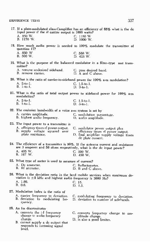
EXPERIENCE TESTS 337
17. If a plate-modulated class-Camplifier has an efficiency of 85% what is the de input power e the rf carrier output is 1000 watts? A. 850 W. C. 1150 W B. 1176 W. D. 1000 W.
18. How much audio power is needed to 100% modulate the transmitter of question 17? A. 850 W B. 500 W.
C. 588 W. D. 425 W.
19. What is the purpose of the balanced modulator in a filter-type sssc trans-mitter? A. remove undesired sideband. C. pass desired band. B. remove carrier. D. A and C above.
20. What is the ratio of carrier-to-sideband power for 100% a-m modulation? A. 2-to-1. C. 1.5-to-1. B. 1-to-1. D. 3-to-1.
21. What is the ratio of total output power to sideband power for 100% a-m modulation? A. 2-to-1. C. 1.5-to-1. B. 1-to-1. D. 3-to-1.
22. The emission bandwidth of a voice a-m system is set by A. carrier amplitude. B. highest audio frequency.
23. The input power to a transmitter is A. efficiency times rf power output. C. modulator power output plus B. supply voltage squared over efficiency times rf power output.
plate resistance. D. final amplifier supply voltage times dc plate current.
24. The efficiency of a transmitter is 90%. If the antenna current and resistance are 3 amperes and 50 ohms respectively, what is the de input power? A. 405 W. C. 500 W. B. 167 W. D. 450 W.
25. What type of meter is used to measure rf current? A. De ammeter. C. Reflectometer. B. Rf ammeter. D. B and C above.
26. What is the deviation ratio in the land mobile services when maximum de-viation is -±5 kHz and highest audio frequency is 3000 Hz? A. 1.66. C. 15. B. 0.6. D. 1.5.
27. Modulation index is the ratio of A. carrier frequency to deviation. B. deviation to modulating fre-
quency.
28. An fm discriminator A. converts :he i-f frequency
change tc audio frequency change.
B. cannot supply a de output that responds to incoming signal level.
C. modulation percentage. D. audio amplitude.
C. D.
modulating frequency to deviation. deviation to number of sidebands.
C. converts frequency change to am-plitude change.
D. is also a good limiter.

338 SECOND-CLASS RADIOTELEPHONE LICENSE HANDBOOK
29. In the land mobile radio services the frequency tolerance is 0.0005%. What is the required tolerance of any frequency meter used in checking these transmitters? A. 0.0005%. C. 0.00025%. B. 0.0025%. D. 0.0001%.
30. Auto-ignition interference is reduced with A. resistance wire in series with C. regulator capacitor.
plugs. D. all of the above. B. generator capacitor.
31. A transmitter operates on 25 MHz. If the frequency tolerance is 0.001%, how far may its carrier drift above and below 25 MHz? A. -±2.5 kHz. C. -±-400 Hz. B. -± 25 kHz. D. ±-250 Hz.
32. If the crystal oscillator of the transmitter in Question 31 operates on 6.25 MHz, how far may the oscillator drift? A. ±-625 Hz. C. ±-100 Hz. B. -1=62.5 llz. D. -±-1000 liz.
33. An absorption wavemeter can be used A. to check frequency of public C. to check for harmonic output.
safety transmitter. D. to check antenna resonance. B. to measure LC circuit
frequency.
34. An fm system as compared to a-m is less subject to A. amplitude noises. C. signal interference. B. receiver noises. D. all of the above.
35. All components in the accepted bandwidth of emission A. must be more than 20 dB down. C. must be within 20 kHz of carrier B. must have a level at least 0.25% frequency.
of total radiated power. D. must be all of the above.
36. Modulation index increases A. with deviation and modulating C. with amplitude of modulating wave
frequency. and decreases with modulating fre-B. with deviation and decreases quency.
with modulating frequency. D. as in B and C above.
37. In land-mobile services narrow-band fm is preferred over the wide-band type because of A. doubling of available channels. C. greater deviation possible. B. better signal-to-noise ratio. D. higher modulation index.
38. Stacking horizontal antennas one above the other A. increases gain. C. improves low-angle vertical radia-B. changes the radiation pattern. tion.
D. does all of the above.
39. A shorted half-wave section of transmission line A. has a high resistive impedance C. has a low resistive impedance at the
at the opposite end. opposite end. B. has an impedance equal to D. displays a high reactance at the op-
surge impedance of line at the posite end. opposite end.

EXPERIENCE TESTS 339
40. A shorted quarter-wave section of transmission line A. has a high resistive impedance C. has a low resistive impedance at the
at the opposite end. opposite end. B. has an impedance equal to its D. displays a high reactance at the op-
surge impedance at the oppo- posite end. site end.
41. Velocity of wave propagation A. is the same at all frequencies. B. rises with frequency.
42. Period of a radio wave is A. one over frequency. B. constant with frequency.
43. A waveguide A. propagates a radio wave by re-
flection. B. is a transmission line with no
inner conductor.
44. A shunt-fed vertical A. uses only a single conductor
transmission line. B. does not have its base grounded.
45. Atmospheric static decreases A. as frequency is increased above
10 MHz. B. with the use of a long antenna.
C. is the product of wavelength and frequency.
D. is both A and C above.
C. product of wavelength and fre-quency.
D. B and C above.
C. D.
is completely enclosed and hollow. is all of the above.
C. has a circular horizontal radiation pattern.
D. is B and C above.
C. when receiver noise is decreased. D. as frequency is decreased below 30
MHz.
46. The resonant frequency of a dipole is decreased by A. adding length. B. adding a series capacitor.
47. At the center of a dipole there is a A. voltage maximum. B. current maximum.
C. mismatching the line. D. A and B above.
C. impedance maximum. D. B and C above.
48. At the top of a quarter-wave vertical there is a A. voltage maximum. B. current maximum.
49. Transconductance is
C. impedance maximum. D. A and C above.
A. a tube parameter that is mea- C. a figure of merit because it shows sured by a good tube tester, how well a tube converts a small B. the quotient of change in grid voltage to a substan-
tial change in plate current. D. all of the above. ilEg •
50. A wattmeter
A. reads true power. C. reads kWh. B. responds to ac input voltage, D. performs A and B above.
current and phase.
51. If a 6-MHz crystal has a positive temperature coefficient of 5 Hz/degree/1 MHz, what happens to crystal frequency if temperature climbs 25 degrees? A. Up 125 Hz. C. Up 150 Hz. B. Up 30 Hz. D. Up 750 Hz.

340 SECOND-CLASS RADIOTELEPHONE LICENSE HANDBOOK
52. A current of 0.5 A is present in a 120-volt 60-Hz relay coil. If the dc resist-ance of the relay is 2 ohms, what is the relay impedance? A. 265. C. 240. B. 60. D. 24.
15-4-1 Drawings
Do drawings of the following from memory:
53. Full-wave rectifier power supply.
54. Synchronous and nonsynchronous vibrator power supplies.
55. Voltage-doubler power supply.
56. Bridge-rectifier power supply.
57. Triode grounded-cathode, grounded-grid and cathode-follower stages.
58. Transistor common-emitter and common-base stages.
59. Single-tube phase splitter.
60. Common-emitter audio power amplifier and grounded-cathode audio power amplifier.
61. RC coupled voltage amplifier driving pentode audio power-output stage.
62. Gain-type phase inverter.
63. Push-pull audio amplifier.
64. Fm discriminator and reactance modulator.
65. Diode detector and audio amplifier.
66. Triode crystal oscillator.
67. Multivibrator.
68. Triode class-C amplifier and tetrode class-C amplifier.
69. Tetrode frequency doubler and push-push frequency doubler.
70. Grounded-grid rf amplifier.
71. Plate-modulated class-C amplifier.
72. Transistor neutralized common-emitter rf amplifier.
73. Pentode RC coupled voltage amplifier.
74. Impedance-coupled amplifier.
75. Block diagram of fm transmitter. If a crystal oscillator operates on 15 MHz and the multiplier consists of two doublers and a tripler, what is the output frequency? A. 30 MHz. C. 90 MHz. B. 180 MHz. D. 15 MHz.
15-4-2. Schematic Questions Refer to Fig. 12-4 when answering the following questions.
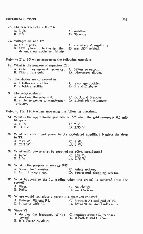
EXPERIENCE TESTS
76. The reactance of the RFC is A. high. B. low.
77. Voltages El and E2 A. are in phase. B. have phase :elationship that
depends on audio amplitude.
C. resistive. D. 50 ohms.
C. D.
are of equal amplitude. are 180° related.
Refer to Fig. 9-5 when answering the following questions.
78. What is the purpose of capacitor Cl? A. Determines resonant frequency. C. Filters ac output. B. Filters transients. D. Discharges diodes.
79. The diodes are connected as A. a full-wave rectifier. B. a bridge rectifier.
80. The relay contacts A. short out the relay coil. B. apply ac power to transformer primary.
C. a voltage doubler. D. B and C above.
C. D. switch off the battery.
do A and B above.
341
Refer to Fig. 14-19 when answering the following questions.
81. What is the approximate grid bias on V2 when the grid current is 0.3 mil-liampere? A. 10 V. C. 2 V. B. 14.1 V. D. 2.35 V.
82. What is the de input power to the modulated amplifier? Neglect the drop in Ti. A. 2.75 W. C. 1 W. B. 26.5 W. D. 4 W.
83. What audio power must be supplied for 100% modulation? A. % W. C. 1.38 W. B. 2 W. D. 2.75 W.
84. What is the purpose of resistor R6? A. Screen load resistor. B. Grid time constant.
C. Safety resistor. D. Screen-grid dropping resistor.
85. What happens to the lb, reading when the crystal is removed from the socket? A. Rises. C. No change. B. Falls. D. Goes to zero.
86. Where would you place a parasitic suppression resistor? A. Between R2 and R3. C. Between R4 and grid of V2. B. In series with R6. D. Between R7 and tank circuit.
87. Stage VI
A. doubles the frequency of the C. requires some Cg, feedback. crystal. D. is both B and C above.
B. is a Pierce oscillator.

342 SECOND-CLASS RADIOTELEPHONE LICENSE HANDBOOK
88. What happens to the lb,: reading when CO is detuned? A. Rises. C. No change. B. Falls. D. Drops to zero.
89. If Li would open, Ib, current would A. rise. C. not change. B. fall. D. go to zero.
90. VI filament burns out. What happens to lb, and IP2 readings? A. Rise. C. Iti up and lb, down. B. Fall. D. Ibi down and h1 up.
1544. Series R nnnnnn ca
91. Find resonant frequency of the circuit. 14iH
A. 7.9 MHz. B. 3.56 MHz. C. 2.23 MHz. D. 5 MHz.
Reg
un 200pF
o
92. For a series-resonant circuit at resonance A. impedance is minimum. B. current is maximum. C. Q = --R—
D. all of the above apply.
93. What is the impedance at resonance? A. More than 100 ohms. C. 100 ohms. B. Resistive. D. B and C above.
94. What is the impedance on the high-frequency side of resonance? A. Higher than 100 ohms. C. Inductive. B. Less than 100 ohms. D. A and C above.
15-4-4. Parallel Reso nnnnn
95. Find resonant frequency of the circuit.
A. 7.95 MHz. B. 3.56 MHz. C. 2.23 MHz. D. 5 MHz.
96. For a parallel-resonant circuit at resonance A. impedance is maximum. C. current I is minimum. B. voltage is maximum. D. all of the above pertain.
97. What is the impedance at resonance? A. More than R. C. Less than R. B. Resistive. D. A and B above.
98. What is the impedance on the high-frequency side of resonance?
A. Lower than R. C. Capacitive. B. Higher than R. D. A and C above.

EXPERIENCE TESTS
99. Purpose of the resonant circuit is
A. to match antenna to receiver.
B. to prevent receiver overload.
C. to trap out interference.
D. for lightning protection.
343
RECEIVER INPUT
100. In the previous circuit A. Li-Cl has maximum imped- C. impedance is minimum for Li-Ci
ance at resonance, and maximum for L2-C2. B. L2-C2 has minimum imped- D. A and B above apply.
ance.
15-6. REVIEW ASSISTANCE
A grade of 75% or higher the first time through Experience Test II should be especially encouraging. However, this should not encourage laxity. You should make an effort to review each question and consider its proper answer. Pay attention to the wrong answers too. Multiple-choice examinations test your knowledge of what is right and what is wrong. Again a grade of less than 75% should not be discouraging. It just indicates that further study and review are imperative. The follow-ing will assist you in your review efforts.
Questions 1 through 10 cover the material in Chapter 14 relating to the FCC rules and Regulations. These emphasize the Public Safety Radio Services although they are appropriate to the other land-mobile services as well. Additional material is to be found in Appendix V. Questions 11 through 25 emphasize a-m modulation systems. If you had a considerable number of these questions incorrect refer back to Chapter 11. A similar coverage of f-m systems related to Chapter 12 are to be found in questions 26 through 37.
If the questions 38 through 48 presented problems, it is necessary to review the subjects of transmission lines and antennas found in Chap-ter 13. Several test-equipment questions, 49 through 52, were given. Review this segment of Chapter 14. A study of schematic diagrams is very important. FCC examination
questions usually do not ask you to draw a complete schematic dia-gram. However, you are often asked to complete the diagram of a cer-tain circuit or to take out a part that is not essential or will result in improper operation of the particular stage. Your best defense for this type of question is to know the individual circuit diagrams called for in the Study Cuide Questions. Reference to specific diagrams is given in the answers to questions 53 through 75. Another line of questioning often followed by the FCC examina-
tions is to give a complete schematic diagram which is then followed

344 SECOND-CLASS RADIOTELEPHONE LICENSE HANDBOOK
by a set of questions related to the schematic. This is the approach used in questions 75 through 100 of Experience Examination II. These questions also place additional stress on resonant circuits. They serve as an excellent summary of the characteristics of series and parallel and resonant combinations.
Before taking the FCC examination take all tests again including those at the end of each chapter.
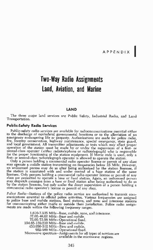
APPENDIX'
Two-Way Radio Assignments
Land, Aviation, and Marine
LAND
The three major land services are Public Safety, Industrial Radio, and Land Transportation.
Public-Safety Radio Services
Public-safety radio services are available for radiocommunications essential either to the discharge of nonfederal governmental functions or to the alleviation of an emergency endangering life or property. Authorizations are made for police radio, fire, forestry conservation, highway maintenance, special emergency, state guard, and local government. All transmitter adjustments or tests which may affect proper operation of the station must be made by or under the supervision of a first- or second-class operator (either radiotelephone or radiotelegraph) who is responsible for the proper functioning of the station equipment. If Morse code is used, only a first- or second-class radiotelegraph operator is allowed to operate the station.
Only a person holding a commercial radio operator license or permit of any class may operate a mobile station transmitting on frequencies below 25 MHz. However, an unlicensed person may do so after being authorized by the station licensee, if the station is associated with and under control of a base station of the same licensee. Only persons holding a commercial radio operator license or permit of any class are permitted to operate a base or fixed station. Again, an unlicensed person may dispatch messages from a base or fixed station after being authorized to do so by the station licensee, but only under the direct supervision of a person holding a commercial radio operator's license or permit of any class.
Police Radio—Stations of the police radio service are authorized to transmit com-munications essential to official police activities. Various frequencies are assigned to police base and mobile stations, fixed stations, and zone and interzone stations for communicating either inside or outside their jurisdiction. Police radio assign-ments are made within the following frequency ranges.
1.610-7.935 MHz—Base, mobile, zone, and interzone. 37.02-46.02 MHz—Base and mobile. 72.02-75.98 MHz—Operational fixed.
154.65-159.210 MHz—Base and mobile. 453.050-512 MHz—Base and mobile.
952-960 MHz—Operational fixed. Microwave spectrum—Assignments for all types of services are
available in the microwave regions.
345

346 SECOND-CLASS RADIOTELEPHONE LICENSE HANDBOOK
Fire Radio—Authorization in the fire radio service is given for stations operated by persons or organizations charged with fire protection. Requests for applications from other than governmental subdivisions must be supported by the governmental subdivision having jurisdiction over the area to be served. Base, mobile, and fixed stations are authorized. Fire-radio frequency assignments are as follows:
1.63 MHz—Base and mobile. 33.42-46.5 MHz—Base, mobile, and fixed.
72.02-75.98 MHz—Operational fixed. 153.77-170.150 MHz—Base, mobile, and fixed.
453.050-512 MHz—Mobile and base. 952-960 MHz—Operational fixed.
Microwave allocations—For all types of services.
Forestry Conservation Radio—Authorizations for stations in the forestry conserva-tion radio service will be issued only to persons or organizations charged with specific forestry conservation activities. Applications from other than governmental subdivisions must be accompanied by a supporting statement from the governmental subdivision having jurisdiction over the area to be served. Frequency assignments are as follows:
2.12-2.244 MHz—Base and mobile. 30.86-45.04 MHz—Base and mobile. 72.02-75.98 MHz—Operational fixed.
151.145-172.375 MHz—Base and mobile. 453.050-458.950 MHz—Base and mobile.
470-512 MHz—Base and mobile. 952-960 MHz—Operational fixed.
Microwave allocations— All services.
Highway Maintenance Radio—Authorizations for stations in the highway-mainte-nance radio service are issued only to governmental subdivisions. Such stations are authorized to transmit communications essential to official highway activities of the licensee. Frequency assignments are as follows:
33.02-47.4 MHz—Base and mobile. 72.02-75.98 MHz—Operational fixed.
150.995-159.195 MHz—Base and mobile. 453.05-458.95 MHz—Base and mobile.
470-512 MHz—Base and mobile. 952-960 MHz—Operational fixed.
Microwave allocations—All services.
Special Emergency Radio Service—This group of allocations is made available tc hospitals, disaster relief organizations, physicians and veterinarians, ambulance operators and rescue organizations, beach patrols, school buses, and in other com-munications systems for emergency use on a standby basis only. Frequency assign-ments are as follows:
2-3 MHz—Fixed. 2.726 MHz—Base and mobile. 3.201 M Hz—Base and mobile.
33.02-47.€6 MHz—Base and mobile. 72.02-75.98 MHz—Operational fixed. 155.16-155.4 MHz—Base and mobile.
952-960 MHz—Operational fixed. Microwave allocations—All services.
State Guard Radio—State-guard radio stations are authorized primarily to transmit communications directly relating to public safety and the protection of life and property, and secondarily to transmit essential nonemergency communications necessary for training and maintaining an efficient organization. The frequency assignments are as follows:
2.726 MHz—Base and mobile. 2.505-3.5 MHz—Used when a second frequency is required.
Local Government Radio—Stations in the local-government radio service are
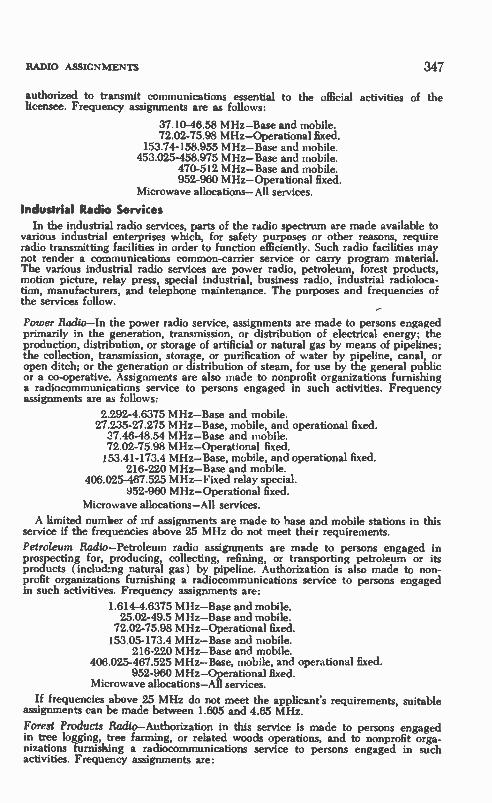
RADIO ASSIGNMENTS 347
authorized to transmit communications essential to the official activities of the licensee. Frequency assignments are as follows:
37.10-46.58 MHz—Base and mobile. 72.02-75.98 MHz—Operational fixed.
153.74-158.955 MHz—Base and mobile. 453.025-458.975 MHz—Base and mobile.
470-512 MHz—Base and mobile. 952-960 MHz—Operational fixed.
Microwave allocations—All services.
Industrial Radio Services
In the industrial radio services, parts of the radio spectrum are made available to various industrial enterprises which, for safety purposes or other reasons, require radio transmitting facilities in order to function efficiently. Such radio facilities may not render a communications common-carrier service or carry program material. The various industrial radio services are power radio, petroleum, forest products, motion picture, relay press, special industrial, business radio, industrial radioloca-tion, manufacturers, and telephone maintenance. The purposes and frequencies of the services follow.
Power Radio—In the power radio service, assignments are made to persons engaged primarily in the generation, transmission, or distribution of electrical energy; the production, distribution, or storage of artificial or natural gas by means of pipelines; the collection, transmission, storage, or purification of water by pipeline, canal, or open ditch; or the generation or distribution of steam, for use by the general public or a co-operative. Assignments are also made to nonprofit organizations furnishing a radiocommunications service to persons engaged in such activities. Frequency assignments are as follows:
2.292-4.6375 MHz—Base and mobile. 27.235-27.275 MHz—Base, mobile, and operational fixed.
37.46-48.54 MHz—Base and mobile. 72.02-75.98 MHz—Operational fixed. 153.41-173.4 MHz—Base, mobile, and operational fixed.
216-220 MHz—Base and mobile. 406.025-467.525 MHz—Fixed relay special.
952-960 MHz—Operational fixed. Microwave allocations—All services.
A limited number of inf assignments are made to base and mobile stations in this service if the frequencies above 25 MHz do not meet their requirements.
Petroleum Radio—Petroleum radio assignments are made to persons engaged in prospecting for, producing, collecting, refining, or transporting petroleum or its products (including natural gas) by pipeline. Authorization is also made to non-profit organizations furnishing a radiocommunications service to persons engaged in such activitives. Frequency assignments are:
1.614-4.6375 MHz—Base and mobile. 25.02-49.5 MHz—Base and mobile.
72.02-75.98 MHz—Operational fixed. 153.05-173.4 MHz—Base and mobile.
216-220 MHz—Base and mobile. 406.025-467.525 MHz—Base, mobile, and operational fixed.
952-960 MHz—Operational fixed. Microwave allocations—All services.
If frequencies above 25 MHz do not meet the applicant's requirements, suitable assignments can be made between 1.605 and 4.65 MHz.
Forest Products Radio—Authorization in this service is made to persons engaged in tree logging, tree farming, or related woods operations, and to nonprofit orga-nizations furnishing a radiocommunications service to persons engaged in such activities. Frequency assignments are:

348 SECOND-CLASS RADIOTELEPHONE LICENSE HANDBOOK
1.676-2.398 MHz—Base and mobile. 27.235-49.58 MHz—Base and mobile. 72.02-75.98 MHz—Operational fixed. 153.05-173.4 MHz—Base and mobile.
216-220 MHz—Base and mobile. 406.025-467.525 MHz—Base, mobile, and operational fixed.
470-512 MHz—Base and mobile. 952-960 MHz—Operational fixed.
Microwave allocations—All services.
If operations above 25 MHz do not meet the applicant's requirements, assign-ments are available between 1.676 and 2.398 MHz.
Motion Picture Radio—Motion-picture radio assignments are made to persons en-gaged in the production of motion pictures, or to nonprofit organizations furnish-ing a radiocommunications service to them. Frequency assignments are:
1.628-4.6375 MHz—Base and mobile. 27.235-27.275 MHz—Base, mobile, and operational fixed.
72.02-75.98 MHz—Operational fixed. 152.87-173.375 MHz—Base and mobile.
952-960 MHz—Operational fixed. Microwave allocations—All services.
If frequencies above 25 MHz do not meet the applicant's requirements, assign-ments can be made between 1.628 and 4.6375 MHz.
Relay Press Radio—Relay-press radio assignments are given to newspapers and press associations. The assignment can be made to nonprofit organizations furnish-ing a radiocommunications service to newspapers and press associations. Frequency assignments are:
27.235-27.275 MHz—Base, mobile, and operational fixed. 72.02-75.98 MHz—Operational fixed.
173.225-173.375 MHz—Base and mobile. 452.975-458 MHz—Base and mobile.
952-960 MHz—Operational fixed. Microwave allocations—All services.
Special Industrial Radio—Quite a few persons and organizations are eligible to hold authorization in the special industrial radio service, including those engaged in farming, ranching, heavy construction (roads, bridges, sewers, pipelines, airfields, and water, oil, gas, or power production), and mining (including the exploration for and development of mining properties). Also eligible are persons rendering certain specialized services essential to industrial operations or public health. Eligibility for special industrial radio service is limited to those engaged in:
1. Plowing, soil conditioning, seeding, fertilizing, or harvesting for agricultural or forestry activities.
2. Sprayng or dusting insecticides, herbicides, or fungicides in areas other than enclosed structures.
3. Livestock breeding. 4. Maintaining, patrolling, and repairing gas or liquid-transmission pipelines,
tank cars, water or waste-disposal wells, industrial storage tanks, or distribu-tion systems of public utilities.
5. Acidizing, cementing, logging, perforating, or shooting activities, and similar services incidental to the drilling of new oil or gas wells, or the maintenance of production from established ones.
6. Supplying of chemicals, mud, tools, pipe, and other unique materials or equip-ment to the petroleum production industry as the primary activity of the ap-plicant: PROVIDED the delivery, installation, or application of these materials require the supplier to use specially fitted conveyances and unusual skills.
7. Delivering ice or fuel to the consumer in solid, liquid, or gaseous form for heating, lighting, refrigerating, or power-generation purposes by means other than pipelines or railroads.
8. Delivering and pouring of ready-mixed concrete or hot asphalt mix.

RADIO ASSIGNMENTS 349
Frequency assignments are:
2.292-4.6375 MHz—Base and mobile. 27.235-49.58 MHz—Base, mobile, and fixed or operational fixed. 72.02-75.98 MHz—Operational fixed.
151.505-173.4 MHz—Base, mobile, and operational fixed. 216-220 MHz—Base and mobile.
406.025-465.625 MHz—Base and mobile. 952-960 MHz—Operational fixed.
Microwave allocations—All services.
Business Radio—Authorizations are made in the business radio service to businesses, schools, philanthropic organizations, clergymen or ecclesiastical institutions, hospi-tals, clinics, and medical associations, and to anyone furnishing a nonprofit radio-communications service to them or their subsidiary. Frequency assignments are:
27.235-43.0 MHz—Base, mobile, and operational fixed 72.02-75.98 MHz—Operational fixed.
150.815-173.4 MHz—Base, mobile, and operational fixed. 216-220 MHz—Base and mobile.
406.025-469.975 MHz—Base, mobile, and operational fixed. 470-512 MHz—Base and mobile. 952-960 MHz—Operational fixed.
Microwave allocations—All services.
Industrial Radiolocation—Industrial radiolocation allocations are made to commer-cial or industrial enterprises which must establish a position, distance, or direction by means of radiolocation devices for purposes other than navigation. An organi-zation furnishing a radiolocation service to such persons can also be authorized. This service is used primarily in geographical, geological, or geophysical activities. Frequency assignments are in the spectrum between 1.605 and 1.8 MHz, at cer-tain frequencies between 3.23 and 3.4 MHz, and in the vhf, microwave, and low-frequency spectrum.
Manufacturers Radio—Assignments in this radio service are macle to persons en-gaged in manufacturing, or in a subsidiary that will furnish a nonprofit radiocom-munications service. Plants, factories, shipyards, or mills which employ power-driven machines and materials-handling equipment to manufacture the complete product, or to assemble it from components, are popularly included in this cate-gory. Establishments engaged primarily in wholesale, retail, or service activities— even though they fabricate or assemble any or all of the commodities handled— are not considered manufacturers, but are classified under the Business Radio Service. Manufacturers radio assignments are:
27.235-27.275 MHz—Base, mobile, or fixed. 153.05-158.43 MHz—Base and mobile.
216-220 MHz—Base and mobile. 451.175-467.525 MHz—Base and mobile.
470-512 MHz—Base and mobile. 952.1-959.9 MHz—Base and mobile.
Telephone Maintenance Radio—Telephone maintenance assignments are given to common-carrier services employed primarily to render a wire-line and/or radio-communications service to the public for hire, or to a nonprofit subsidiary that furnishes the radio service. Frequency allocations are:
27.235-43.16 MHz—Base, mobile, and fixed. 151.985-158.34 M I Iz — Base and mobile.
451.175-467.525 MHz- Base and mobile.
Land Transportation Radio Services
Part of the radio spectrum is reserved for certain land-transportation communi-cations. These radio facilities cannot be used for hire or to carry program material, but are provided for motor-carrier radio, railroad, taxicab, and automobile emer-gency. As in almost all other two-way radio services, all transmitter adjustments or tests which may affect its operation must be made by or under the immediate

350 SECOND-CLASS RADIOTELEPHONE LICENSE HANDBOOK
supervision of a first- or second-class commercial radio operator, either radiotele-phone or radiotelegraph. The radiotelegraph license is required if the station trans-mits Morse code. Motor Carrier Radio—Authorization for stations in the motor-carrier radio service is issued to bus lines, trucking companies, and moving and storage firms operating buses or trucks within a city, or from city to city; or to a nonprofit organization furnishing a radiocommunications service on a cost-sharing basis to persons en-gaged in such activities. Frequency assignments are:
27.235-27.275 MHz—Base, mobile, and operational fixed. 30.66-44.6 MHz—Base and mobile.
72.02-75.98 MHz—Operational fixed. 159.495-160.2 MHz—Base and mobile.
452.325-457.875 MHz—Base and mobile. 952-960 MHz—Operational fixed.
Microwave allocations—All services.
Railroad Radio—Railroad service authorization is given to railroads, including rail-way express companies owned wholly by the railroad. Assignment can again be made to a nonprofit organization furnishing the radiocommunications service to the railroad. Frequency assignments are:
27.235-27.275 MHz—Base, mobile, and operational fixed. 72.02-75.98 MHz— Fixed.
160.215-161.565 MHz—Base and mobile. 452.325-457.95 MHz—Base and mobile. Microwave allocations— All services.
Taxicab Radio—Persons who carry passengers for hire—provided they do not fol-low a schedule, or operate over a regular route or between established terminals— are eligible. Eligibility can be extended to a nonprofit organization furnishing such a radiocommunications service. Frequency assignments are as follows:
27.235-27.275 MHz—Base, mobile, and operational fixed 152.27-157.71 MHz—Base and mobile. 452.05-457.5 MHz—Base and mobile.
Microwave allocations—All services.
Automobile Emergency Radio—Associations, owners of private automobiles, and public garages providing emergency road service are eligible. Information to be transmitted is restricted to the safety of life or the protection of important prop-erty, and to dispatching repair trucks and cars to disabled vehicles. Frequency al-locations are as follows:
27.235-27.275 MHz—Base and mobile. 150.815-157.5 MHz—Base and mobile. 452.525-452.6 MHz—All services.
Microwave allocations—Base, mobile, and operational fixed.
ADDITIONAL LAND-MOBILE ASSIGNMENTS
Several land-mobile assignments in the lower portion of the uhf ty band ( chan-nels 14-20) are available in the ten largest metropolitan areas. Permanent allocation of uhf channels 70-83 to the mobile services has been made.
Private land-mobile services have been assigned 881-902 MHz and 928-960 MHz; common-carrier mobile, 806-881 MHz.
AVIATION
In the aviation radio services, the second-class radiotelephone operator can op-erate, install, adjust and maintain aviation radiotelephone equipment, but not radio-telegraph stations. The many types of aeronautical radio stations are listed in Appendix II.

RADIO ASSIGNMENTS 351
The bulk of aeronautical radio-station assignments is in the frequency spectrum between 118 and 135 MHz, with additional assignments between 2.8 and 18 MHz. Operational fixed stations are assigned between 72.02 and 75.98 MHz, plus addi-tional microwave allocations. Some of the radionavigational frequency assignments are as follows:
Localizer station-108.1-111.9 MHz Glide-path station-328.6-335.4 MHz
Aeronautical marker beacon-75 MHz Radio range station-108.2-117.9 MHz
Radio beacon station-200-415 kHz Microwave assignments—Available for distance-measuring and
other navigational functions.
Some key aircraft frequency assignments available to aircraft stations are: 410 kHz
457 kHz
8364 kHz
121.5 MHz
121.6 MHz
121.60, 121.65, 121.70, 121.75, 121.80, 121.85, 121.90, and 121.95 MHz 118-134.95 MHz Miscellaneous maritime frequencies
420-460 MHz
960-1215 MHz
1300-1660 MHz, excluding 1350-1400 MHz 5250-5440, 9000-9200, 9300-9320, and 9320-9500 MHz 8750-8850, and 9750-9850 MHz
13250-13400 MHz
International direction-finding frequency for use outside the continental United States. International calling and distress frequency for ships and air-craft over the seas. Transmission on this frequency, except urgent and safety messages and signals, must cease twice each hour for three minutes beginning at 15 and 45 minutes past the hour, Greenwich civil time. For lifeboats, life rafts, and other survival craft communicat-ing with maritime stations during rescue operations. Universal simplex emergency and distress frequency used by aircraft for emergency direction-finding purposes, to establish air-ground communications in emergencies, and for search and rescue operations by aircraft not equipped to transmit on 121.6 MHz. This frequency will not be assigned to an aircraft unless other frequencies have also been assigned to accommodate its normal needs. For air-to-air and air-to-ground communications with aero-nautical search and rescue stations engaged in search and rescue operations. Airport utility frequencies. 121.60 MHz can be used by aircraft radio stations for airport utility communications, provided that search and rescue communications are not interefered with in the locale (luring any such operations.
For air traffic and airport control. Calling and working frequencies of ship stations may also be assigned to aircraft stations for the purpose of communicating with coastal ships stations, provided they do not interfere with other ship or coastal stations. For aircraft radio altimeter functions. The aeronautical radio-navigation service will not he permitted to use the 420-460— MHz band after February 15, 1963. For distance measuring and other functions related to those performed in the 1400-1660—MHz band. For an integrated system of electronic aids to air navigation and traffic control.
For airborne radar, provided it does not interfere with preci-sion radar operations in the 9000-9180—MHz band.
For temporary use by airborne Doppler radars until moved to the frequency band allocated to the aeronautical radio-naviga-tion service. Any interference to airborne Doppler radars from the radiopositioning service must be tolerated in this band. For airborne Doppler radar use.

352 SECOND-CLASS RADIOTELEPHONE LICENSE HANDBOOK
Other frequencies required for overseas and foreign operation may also be made available upon showing that a need exists. In addition, a licensee, when operating an aircraft station outside the United States (as defined in the Communications Act of 1934, as amended) may communicate with any ground station on its as-signed frequency. The calling and working frequency is 3117.5 kHz for commercial and 3023.5 kHz
for private aircraft. Air traffic-control frequencies for private aircraft extend be-tween 122.0 and 123.05 MHz. Two specialized frequencies within this spectrum are 122.8 MHz, assigned to
aeronautical advisory stations and private aircraft stations (also for establishing communications between private aircraft in flight), and 123 MHz, for contact be-tween private aircraft and aeronautical advisory stations only. The Civil Air Patrol has specific frequency assignments at 2.374, 4.4675, 4.5075,
4.585, 26.620, 143.91, and 148.14 MHz. CAP radiotelephone equipment must be installed and serviced by or under the supervision of a second- or first-class radio-telephone license holder.
MARINE
In the maritime services, two-way radio equipment is mandatory on certain small coastal boats and all seagoing vessels. Hence, there are a variety of land and shipboard radio stations that require the services of licensed radio operators. The installation, adjustment, and maintenance of many marine stations licensed for radiotelephony comes under the jurisdiction of a second- or first-class radiotele-phone license holder. Two-way radio equipment is mandatory on all vessels, how-ever small, that carry more than six passengers for hire; and it has become increas-ingly common on many smaller boats plying our coastal and inland waters.
All licensed radio operators should be familiar with the distress frequencies, priorities, and procedures—which take on added significance in marine and avia-tion two-way radiocommunications. The six key distress and emergency frequencies are:
500 kHz Ships and over-the-sea aircraft; radiotelegraphy. 8.364 MHz Survival craft; lifeboats and life rafts; rescue operations. 121.5 MHz Aeronautical emergency and distress frequency; emergency direction
finding. 121.6 MHz Air-to-air and air-to-ground search and rescue operations. 2.182 MHz Maritime distress frequency; radiotelephony. 156.8 MHz Distress, harbor safety and calling.
Small-boat installations are largely radiotelephone operating in the medium-frequency and vhf2 bands. Practically all stations have an operating channel on either 2.182 or 156.8 MHz, or both, for distress and emergency calls.
Coast stations open to public correspondence have a variety of frequency assign-ments between 2.182 and 22.716 MHz, as well as additional assignments according to need and location on 35.14, 35.18, and 156-162 MHz.
Similar frequency assignments are available for limited-coast and marine-utility stations. They receive or transmit safety communications from ships or land sta-tions, and communicate with the proper categories of ship stations about their business or operational needs. They can also communicate with limited-ship stations and with marine-utility
stations on board ship, as well as with public ship stations using telephony. All communications must be on their assigned frequency, and they are not open to public correspondence.
Shipboard stations using radiotelephony are assigned certain spot frequencies between 2 and 23 MHz or between 156 and 162 MHz. Many small-boat frequency assignments are between 1.605 and 2.85 MHz.

APPENDIX II
Definitions of Station Assignments from the
FCC Rules and Regulations
Sec. 2.1 Definitions. The following definitions are issued: Active satellite. An earth satellite carrying a station intended to transmit or re-
transmit radiocommunication signals. Aeronautical advisory station. An aeronautical station used for advisory and civil
defense communications primarily with private aircraft stations. Aeronautical fixed service. A fixed service intended for the transmission of in-
formation relating to air navigation, preparation for and safety of flight. Aeronautical fixed station. A station in the aeronautical fixed service. Aeronautical mobile service. A mobile service between aeronautical stations and
aircraft stations, or between aircraft stations, in which survival craft stations may also participate.
Aeronautical muiticom land station. An aeronautical station operating in the aero-nautical multicom service.
Aeronautical multicom mobile station. A mobile station operating in the aeronau-tical multicom service.
Aeronautical multicom service. A mobile service not open to public correspond-dence, used to provide communications essential to conduct of activities being per-formed by or directed from private aircraft.
Aeronautical radionavigation service. A radionavigation service intended for the benefit of aircraft.
Aeronautical search and rescue station. A land or mobile station in the aeronau-tical mobile service used for communication with aircraft and other aeronautical search and rescue stations pertaining to search and rescue activities with aircraft.
Aeronautical station. A land station in the aeronautical mobile service. In certain instances an aeronautical station may be placed on board a ship or an earth satel-lite.
Aeronautical telemetering land station. A telemetering land station used in the flight testing of manned or unmanned aircraft, missiles, or major components thereof.
Aeronautical telemetering mobile station. A telemetering mobile station used in the flight testing of manned or unmanned aircraft, missiles, or major components thereof.
Aeronautical utility land station. A land station located at airdrome control tow-ers and used for control of ground vehicles and aircraft on the ground at airdromes.
Aeronautical utility mobile station. A mobile station used for communication, at airdromes, with the aeronautical utility land station, ground vehicles, and aircraft on the ground.
Aircarrier aircraft station. An aircraft station aboard an aircraft engaged in, or essential to, transportation of passengers or cargo for hire.
Aircraft station. A mobile station in the aeronautical mobile service on board an aircraft or an airspace vehicle.
353

354 SECOND-CLASS RADIOTELEPHONE LICENSE HANDBOOK
Airdrome control station. An aeronautical station providing communication be-tween an airdrome control tower and aircraft.
Amateur service. A service of self-training, intercommunication and technical in-vestigations carried on by amateurs, that is, by duly authorized persons interested in radio technique solely with a personal aim and without pecuniary interest. Amateur station. A station in the amateur service. Aural broadcast intercity relay station. A fixed station utilizing telephony for the
transmission of aural program material between broadcasting stations other than international broadcasting stations, for simultaneous or delayed broadcast.
Aural broadcast STL station. A fixed station utilizing telephony for the trans-mission of aural program material between a studio and the transmitter of a broad-casting station other than an international broadcasting station, for simultaneous or delayed broadcast.
Authorized frequency. The frequency assigned to a station by the Commission and specified in the instrument of authorization.
Authorized power. The power assigned to a radio station by the Commission and specified in the instrument of authorization. The authorized power does not necessarily correspond to the power used by the Commission for purposes of its Master Frequency Record (MFR) and notification to the International Telecom-munication Union.
Aviation instructional station. A land or mobile station in the aeronautical mobile service used for radiocommunications pertaining to instructions to students or pilots while actually operating aircraft or engaged in soaring activities.
Aviation services. Aviation services are primarily for the safe, expeditious and economical operation of aircraft. They include the aeronautical fixed service, aero-nautical radionavigation service, and secondarily, the handling of public corre-spondence to and from aircraft.
Baseband. In the process of modulation, the baseband is the frequency band occupied by the aggregate of the modulating signals when first used to modulate a carrier.
Base station. A land station in the land mobile service carrying on a service with land mobile stations.
Broadcasting service. A radiocommunication service in which the transmissions are intended for direct reception by the general public. This service may include sound transmissions, television transmissions or other types of transmissions.
Broadcasting station. A station in the broadcasting service.
Carrier. In a frequency stabilized system, the sinusoidal component of a modu-lated wave whose frequency is independent of the modulating wave; or the out-put of a transmitter when the modulating wave is made zero; or a wave generated at a point in the transmitting system and subsequently modulated by the signal; or a wave generated locally at the receiving terminal which, when combined with the sidebands in a suitable detector, produces the modulating wave.
Carrier frequency. The frequency of the carrier. Citizens Radio Service. A radiocommunication service of fixed, land, and mobile
stations intended for personal or business radiocommunications, radio signaling, control of remote objects or devices by means of radio and other purposes not spe-cifically prohibited.
Civil Air Patrol land station. A land station used exclusively for communications of the Civil Air Patrol.
Civil Air Patrol mobile station. A mobile station used exclusively for communica-tions of the Civil Air Patrol.
Coast station. A land station in the martime mobile service. Common carrier fixed station. A fixed station open to public correspondence. Common carrier land station. A land station open to public correspondence. Common carrier mobile station. A mobile station open to public correspondence. Communication-satellite earth station. An earth station in the communication-
satellite service. Communication-satellite service. A space service:
—between earth stations, when using active or passive satellites for the exchange of communications of the fixed or mobile service, or
—between an earth station and stations on active satellites for the exchange of corn-
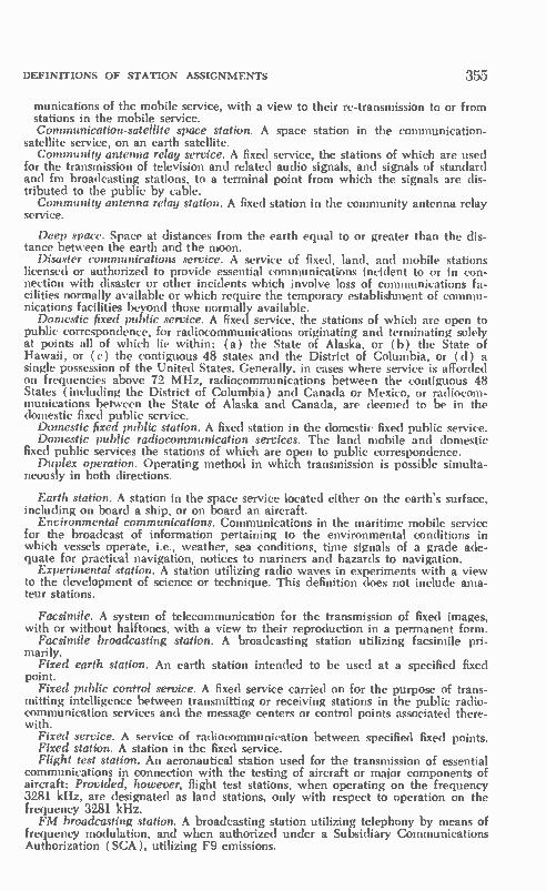
DEFINITIONS OF STATION ASSIGNMENTS 355
munications of the mobile service, with a view to their re-transmission to or from stations in the mobile service. Communication-satellite space station. A space station in the communication-
satellite service, on an earth satellite. Community antenna relay service. A fixed service, the stations of which are used
for the transmission of television and related audio signals, and signals of standard and fm broadcasting stations, to a terminal point from which the signals are dis-tributed to the public by cable. Community antenna relay station. A fixed station in the community antenna relay
service.
Deep space. Space at distances from the earth equal to or greater than the dis-tance between the earth and the moon.
Disaster communications service. A service of fixed, land, and mobile stations licensed or authorized to provide essential communications incident to or in con-nection with disaster or other incidents which involve loss of communications fa-cilities normally available or which require the temporary establishment of commu-nications facilities beyond those normally available.
Domestic fixed public service. A fixed service, the stations of which are open to public correspondence, for radiocommunications originating and terminating solely at points all of which lie within: (a) the State of Alaska, or (b) the State of Hawaii, or (c) the contiguous 48 states and the District of Columbia, or (d) a single possession of the United States. Generally, in cases where service is afforded on frequencies above 72 MHz, radiocommunications between the contiguous 48 States (including the District of Columbia) and Canada or Mexico, or radiocom-munications between the State of Alaska and Canada, are deemed to be in the domestic fixed public service.
Domestic fixed public station. A fixed station in the domestic fixed public service. Domestic public radiocommunication services. The land mobile and domestic
fixed public services the stations of which are open to public correspondence. Duplex operation. Operating method in which transmission is possible simulta-
neously in both directions.
Earth station. A station in the space service located either on the earth's surface, including on board a ship, or on board an aircraft.
Environmental communications. Communications in the maritime mobile service for the broadcast of information pertaining to the environmental conditions in which vessels operate, i.e., weather, sea conditions, time signals of a grade ade-quate for practical navigation, notices to mariners and hazards to navigation.
Experimental station. A station utilizing radio waves in experiments with a view to the development of science or technique. This definition does not include ama-teur stations.
Facsimile. A system of telecommunication for the transmission of fixed images, with or without halftones, with a view to their reproduction in a permanent form.
Facsimile broadcasting station. A broadcasting station utilizing facsimile pri-marily.
Fixed earth station. An earth station intended to be used at a specified fixed point.
Fixed public control service. A fixed service carried on for the purpose of trans-mitting intelligence between transmitting or receiving stations in the public radio-communication services and the message centers or control points associated there-with.
Fixed service. A service of radiocommunication between specified fixed points. Fixed station. A station in the fixed service. Flight test station. An aeronautical station used for the transmission of essential
communications in connection with the testing of aircraft or major components of aircraft: Provided, however, flight test stations, when operating on the frequency 3281 kHz, are designated as land stations, only with respect to operation on the frequency 3281 kHz. FM broadcasting station. A broadcasting station utilizing telephony by means of
frequency modulation, and when authorized under a Subsidiary Communications Authorization (SCA), utilizing F9 emissions.
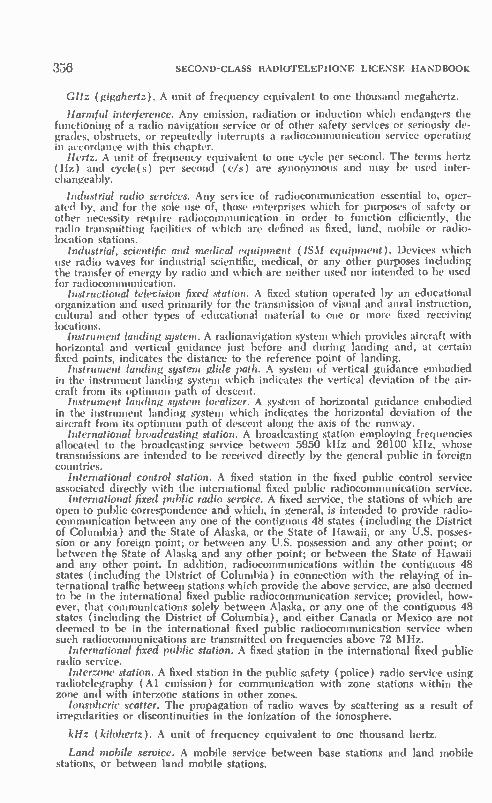
356 sEcOND-cLAss RADIOTELEPHONE LICENSE HANDBOOK
GHz (gigahertz). A unit of frequency equivalent to one thousand megahertz.
Harmful interference. Any emission, radiation or induction which endangers the functioning of a radio navigation service or of other safety services or seriously de-grades, obstructs, or repeatedly interrupts a radiocommunication service operating in accordance with this chapter.
Hertz. A unit of frequency equivalent to one cycle per second. The terms hertz (Hz) and cycle( s) per second (c/s) are synonymous and may be used inter-changeably.
Industrial radio services. Any service of radiocommunication essential to, oper-ated by, and for the sole use of, those enterprises which for purposes of safety or other necessity require radiocommunication in order to function efficiently, the radio transmitting facilities of which are defined as fixed, land, mobile or radio-location stations.
Industrial, scientific and medical equipment (ISM equipment). Devices which use radio waves for industrial scientific, medical, or any other purposes including the transfer of energy by radio and which are neither used nor intended to be used for radiocommunication.
Instructional television fixed station. A fixed station operated by an educational organization and used primarily for the transmission of visual and aural instruction, cultural and other types of educational material to one or more fixed receiving locations.
Instrument landing system. A radionavigation system which provides aircraft with horizontal and vertical guidance just before and during landing and, at certain fixed points, indicates the distance to the reference point of landing.
Instrument landing system glide path. A system of vertical guidance embodied in the instrument landing system which indicates the vertical deviation of the air-craft from its optimum path of descent.
Instrument landing system localizer. A system of horizontal guidance embodied in the instrument landing system which indicates the horizontal deviation of the aircraft from its optimum path of descent along the axis of the runway.
International broadcasting station. A broadcasting station employing frequencies allocated to the broadcasting service between 5950 kHz and 26100 kHz, whose transmissions are intended to be received directly by the general public in foreign countries.
International control station. A fixed station in the fixed public control service associated directly with the international fixed public radiocommunication service.
International fixed public radio service. A fixed service, the stations of which are open to public correspondence and which, in general, is intended to provide radio-communication between any one of the contiguous 48 states (including the District of Columbia) and the State of Alaska, or the State of Hawaii, or any U.S. posses-sion or any foreign point; or between any U.S. possession and any other point; or between the State of Alaska and any other point; or between the State of Hawaii and any other point. In addition, radiocommunications within the contiguous 48 states (including the District of Columbia) in connection with the relaying of in-ternational traffic between stations which provide the above service, are also deemed to be in the international fixed public radiocommunication service; provided, how-ever, that communications solely between Alaska, or any one of the contiguous 48 states (including the District of Columbia), and either Canada or Mexico are not deemed to be in the international fixed public radiocommunication service when such radiocommunications are transmitted on frequencies above 72 MHz.
International fixed public station. A fixed station in the international fixed public radio service.
Interzone station. A fixed station in the public safety (police) radio service using radiotelegraphy (Al emission) for communication with zone stations within the zone and with interzone stations in other zones.
lonspheric scatter. The propagation of radio waves by scattering as a result of irregularities or discontinuities in the ionization of the ionosphere.
kHz (kilohertz). A unit of frequency equivalent to one thousand hertz.
Land mobile service. A mobile service between base stations and land mobile stations, or between land mobile stations.

DEFINITIONS OF STATION ASSIGNMENTS 357
Land mobile station. A mobile station in the land mobile service capable of sur-face movement within the geographical limits of a country or continent. Land station. A station in the mobile service not intended to be used while in
motion. Land transportation radio service. Any private service of radiocommunication es-
sential to the conduct of certain land transportation activities and operated for the use of persons engaged in those activities, the transmitting facilities of which are defined as fixed, land, mobile or radiolocation stations.
Localizer station. A radionavigation land station in the aeronautical radionaviga-tion service which provides signals for the lateral guidance of aircraft with respect to a runway centerline.
Loran station. A long distance radionavigation land station transmitting synchro-nized pulses. Hyperbolic fines of position are determined by the measurement of the difference in the time of arrival of these pulses.
Marine radiobeacon station. A radionavigation land station, the emissions of which are intended to enable a ship station to determine its bearing or its direction in relation to the marine radiobeacon station.
Maritime mobile service. A mobile service between coast stations and ship sta-tions, or between ship stations, in which survival craft stations may also participate.
Maritime radionavigation service. A radionavigation service intended for the benefit of ships.
Marker beacon. A transmitter in the aeronautical radionavigation service which radiates vertically a distinctive pattern for providing position information to air-craft. MHz (megahertz). A unit of frequency equivalent to one million hertz. Meteorological aids service. A radiocommunication service used for meteorologi-
cal, including hydrological, observations and exploration. Meteorological-satellite earth station. An earth station in the meteorological-
satellite service. Meteorological-satellite service. A space service in which the results of meteoro-
logical observations, made by instruments on earth satellites, are transmitted to earth stations by space stations on these satellites.
Meteorological-satellite space station. A space station in the meteorological-satel-lite service, on an earth satellite. Mobile earth station. An earth station intended to be used while in motion or
during halts at unspecified points. Mobile, except television pickup, station. Any mobile station other than a tele-
vision pickup station. Mobile service. A service of radio communication between mobile and land
stations, or between mobile stations. Mobile station. A station in the mobile service intended to be used while in
motion or during halts at unspecified points. Modulation. The process of producing a wave some characteristic of which
varies as a function of the instantaneous value of another wave, called the modulat-ing wave.
Omnidirectional range station. A radionavigation land station in the aeronauti-cal radionavigation service providing direct indication of the bearing (omnibear-ing) of that station from an aircraft.
Operational fixed station. A fixed station, not open to public correspondence, operated by and for the sole use of those agencies operating their own radiocom-munication facilities in the public safety, industrial, land transportation, marine, or aviation service.
Operational land station. A land station, excluding aeronautical stations, not open to public correspondence, operated by and for the sole use of those agencies operating their own radiocommunication facilities in the public safety, industrial, land transportation, marine, or aviation services.
Operational mobile station. A mobile station, excluding aircraft stations, not open to public correspondence, operated by and for the sole use of those agencies operating their own radiocommunication facilities in the public safety, industrial, land transportation, marine, or aviation services.

358 SECOND-CLASS RADIOTELEPHONE LICENSE HANDBOOK
Passive satellite. An earth satellite intended to transmit radiocommunication sig-nals by reflection.
Port operations. Communications in or near a port, or in locks or waterways, between coast stations and ship stations, or between ship stations, in which mes-sages are restricted to those relating to the operational handling, the movement and the safety of ships and, in emergency, to the safety of persons. Messages which are of a public correspondence nature shall be excluded.
Primary standard of frequency. The primary standard of frequency for radio frequency measurements shall be the standard of frequency maintained by the National Bureau of Standards, Department of Commerce, Boulder, Colorado. The operating frequency of all radio stations will be determined by comparison with this standard or through the standard signals of stations WWV, WWVH, or WWVB of the National Bureau of Standards.
Private aircraft station. An aircraft station on board an aircraft not operated as an air carrier.
Public correspondence. Any telecommunication which the offices and stations must, by reason of their being at the disposal of the public, accept for transmission.
Public safety radio service. Any service of radiocommunication essential either to the discharge of non-Federal governmental functions or the alleviation of an emergency endangering life or property, the radio transmitting facilities of which are defined as fixed, land, mobile, or radiolocation stations.
flacon. A radionavigation system transmitting, automatically or in response to a predetermined received signal, a pulsed radio signal with specific characteristics.
flacon station. A radionavigation land station which employs a racon. Radar. A radiodetermination system based on comparison of reference signals
with radio signals reflected, or retransmitted, from the position to be determined. Radio. A general term applied to the use of radio waves. Radio altimeter. A radionavigation equipment, on board an aircraft, which
makes use of the reflection of radio waves from the ground to determine the height of the aircraft above the ground.
Radio astronomy. Astronomy based on the reception of radio waves of cosmic origin.
Radio astronomy service. A service involving the use of radio astronomy. Radio astronomy station. A station in the radio astronomy service. Radiobeacon station. A station in the radionavigation service the emissions of
which are intended to enable a mobile station to determine its bearing or direc-tion in relation to the radiobeacon station.
Radiocommunication. Telecommunication by means of radio waves. Radiodetermination. The determination of position, or the obtaining of informa-
tion relating to position, by means of the propagation properties of radio waves. Radiodetermination service. A service involving the use of radiodetermination. Radiodetermination station. A station in the radiodetermination service. Radio direction-finding. Radiodeterminaton using the reception of radio waves
for the purposes of determining the direction of a station or object. Radio direction-finding station. A radiodetermination station using radio direc-
tion-finding. Radiolocation. Radiodetermination used for purposes other than those of radio-
navigation. Radiolocation land station. A station in the radiolocation service not intended to
be used while in motion. Radiolocation mobile station. A station in the radiolocation services intended to
be used while in motion or during halts at unspecified points. Radiolocation service. A radiodetermination service involving the use of radio-
location. Radionavigation. Radiodetermination used for the purposes of navigation, in-
cluding obstruction warning. Radionavigation land station. A station in the radionavigation service not in-
tended to be used while in motion. Radionavigation land test station (MTF). A radionavigation land station ( Main-
tenance Test Facility) in the aeronautical radionavigation service which is used as a radionavigation calibration station for the transmission of essential information in connection with the testing and calibration of aircraft navigational aids, receiving

DEFINITIONS OF STATION ASSIGNMENTS 359
equipment, and interrogators at predetermined surface locations. The primary pur-pose of this facility is to permit maintenance testing by aircraft radio service per-sonnel.
Radionavigation land test station (OTF). A radionavigation land station (Oper-ational Tests Facility) in the aeronautical radionavigation service which is used as a radionavigation calibration staton for the transmission of essential information in connection with the testing and calibration of aircraft navigational aids, receiving equipment, and interrogators at predetermined surface locatoins. The primary pur-pose of this facility is to permit the pilot to check a radionavigation system aboard the aircraft prior to takeoff.
Radionavigation mobile station. A station in the radionavigation service intended to be used while in motion or during halts at unspecified points.
Radionavigation-satellite earth station. An earth station in the radionavigation-satellite service.
Radionavigation-satellite service. A service using space stations on earth satel-lites for the purpose of radionavigation, including, in certain cases, transmission or re-transmission of supplementary information necessary for the operation of the radionavigation system.
Radionavigation-satellite space station. A space station in the radionavigation-satellite service, on an earth satellite.
Radionavigation service. A radiodetermination service involving use of radio-navigation.
Radio range station. A radionavigation land station in the aeronautical radionavi-gation service providing radial equisignal zones.
Radiosonde. An automatic radio transmitter in the meteorological aids service usually carried on an aircraft, free balloon, kite or parachute, and which transmits meteorological data.
Radiosonde station. A station in the meterological aids service employing a radiosonde.
Radio waves (or Hertzian waves). Electromagnetic waves of frequencies lower than 3000 GHz propogated in space without artificial guide. Remote pickup broadcast base station. A base station licensed for communicat-
ing with remote pickup broadcast mobile stations. Remote pickup mobile station. A land mobile station licensed for the transmission
of program material and related communications from the scene of events which occur outside a studio to broadcasting station, and for communicating with other remote pickup broadcast base and mobile stations.
Safety service. A radiocommunication service used permanently or temporarily for the safeguarding of human life and property.
Ship station. A mobile station in the maritime mobile service located on board a vessel, other than a survival craft, which is not permanently moored.
Simplex operation. Operating method in which transmission is made possible alternately in each direction, for example, by means of manual control.
Spacecraft. Any type of space vehicle including an earth satellite or a deep-space probe, whether manned or unmanned.
Space research earth station. An earth station in the space research service. Space research service. A space service in which spacecraft or other objects in
space are used for scientific or technological research purposes. Space research space station. A space station in the space research service. Space telecommand. The use of radiocommunciation for the transmission of
signals to a space station to initiate, modify or terminate functions of the equip-ment on a space object, including the space station.
Space telemetering. The use of telemetering for the transmission from a space stations of results of measurements made in a spacecraft, including those relating to the functioning of the spacecraft.
Space tracking. Determination of the orbit, velocity or instantaneous position of an object in space by means of radio determination, excluding primary radar, for the purpose of following the movement of the object.
Space service. A radiocommunication service: —between earth stations and space stations, —or between space stations, —or between earth stations when the signals are retransmitted by space stations,

360 SECOND-CLASS RADIOTELEPHONE LICENSE HANDBOOK
or transmitted by reflection or scattering by the ionosphere or within the earth's atmosphere. Space station. A station in the space service located on an object which is be-
yond, is intended to go beyond, or has been beyond, the major portion of the earth's atmosphere.
Standard broadcasting station. A broadcasting station operated on a frequency in the band 535-1605 kHz.
Standard frequency service. A radiocommunication service for scientific, tech-nical and other purposes, providing the transmission of specified frequencies of stated high precision, intended for general reception.
Stationary satellite. A satellite, the circular orbit of which lies in the plane of the earth's equator and which turns about the polar axis of the earth in the same di-rection and with the same period as those of the earth's rotation.
Survival craft station. A mobile station in the maritime or aeronautical mobile service intended solely for survival purposes and located on any lifeboat, liferaft or other survival equipment.
Telecommunication. Any transmission, emission or reception of signs, signals, writing, images, and sounds, or intelligence of any nature by wire, radio, optical or other electromagnetic systems.
Telegraphy. A system of telecommunication which is concerned in any process providing transmission and reproduction at a distance of documentary matter, such as written or printed matter or fixed images, or the reproduction at a distance of any kind of information in such form. The foregoing definition appears in the International Telecommunication Convention, but, for the purposes of the Com-mission's rules, telegraphy shall mean, unless otherwise specified, "A system of telecommunication for the transmission of written matter by the use of a signal code."
Telemetering. The use of telecommunication for automatically indicating or recording measurements at a distance from the measuring instrument.
Telemetering fixed station. A fixed station, the emissions of which are used for telemetering.
Telemetering land station. A land station, the emissions of which are used for telemetering.
Telemetering mobile station. A mobile station, the emissions of which are used for telemetering.
Telephony. A system of telecommunication set up for the transmission of speech or, in some cases, other sounds.
Television. A system of telecommunication for transmission of transient images of fixed or moving objects.
Television broadcasting station. A broadcasting station utilizing both television and telephony to provide combination and simultaneous visual and aural programs intended to be received directly by the general public.
Television intercity relay station. A fixed station used for intercity transmission of television program material and related communications for use by television broadcast stations.
Television pickup station. A land mobile station used for the transmission of television program material and related communications from the scenes of events occurring at points removed from television broadcast station studios to television broadcast stations.
Television STL station (studio-transmitter link). A fixed station used for the transmission of television program material and related communications from a studio to the transmitter of a television broadcast station.
Terrestrial service. Any radio service defined in this Part, other than a space service or the radio astronomy service.
Terrestrial station. A station in a terrestrial service. Tropospheric scatter. The propagation of radio waves by scattering as a result
of irregularities or discontinuities in the physical properties of the troposphere.
Zone station. A fixed station in the public safety (police) radio service using radiotelegraph (Al emission) for communication with other similar stations in the same zone and with an interzone station.

APPENDIX III
Reference Material for Elements I and ll Study
Extracts from the Geneva, 1959, Treaty and
the Communications Act of 1934, as Amended
SECTION III TECHNICAL CHARACTERISTICS
PARAGRAPH 93. Harmful interference: Any emission, radiation or induction which endangers the functioning of radionavigation service or of other safety services or seriously degrades, obstructs or repeatedly interrupts a radiocommunication service operating in accordance with these Regulations.
ARTICLE 21 INSPECTION OF MOBILE STATIONS
838 SEC. 1. (1) The governments or appropriate administrations of countries which a mobile station visits, may require the production of the license for exam-ination. The operator of the mobile station, or the person responsible for the station, shall facilitate this examination. The license shall be kept in such a way that it can be produced upon request. As far as possible, the license, or a copy certified by the authority which has issued it, should be permanently exhibited in the station.
ARTICLE 37
PARAGRAPH 1496 The term "communication" as used in this Article means ra-diotelegrams as well as radiotelephone calls. The order of priority for communica-tions in the mobile service shall be as follows:
1. Distress calls, distress messages, and distress traffic. 2. Communications preceded by the urgency signal. 3. Communications preceded by the safety signal. 4. Communications relating to radio direction-finding. 5. Communications relating to the navigation and safe movement of aircraft. 6. Communications relating to the navigation, movements, and needs of ships, and weather observation messages destined for an official meteorological service. 7. Government radiotelegrams: Prioritè Nations.
361

362 SECOND-CLASS RADIOTELEPHONE LICENSE HANDBOOK
8. Government communications for which priority has been requested. 9. Service communications relating to the working of the radiocommunications previously exchanged. 10. Government communications other than those shown in 7 and 8 above, and all other communications.
• • • • • • •
Sec. 303 Except as otherwise provided in this Act, the Commission from time to time, as public convenience, interest, or necessity requires shall—(m) (1) Have authority to suspend the license of any operator upon proof sufficient to satisfy the Commission that the licensee:
(A) Has violated any provision of any Act, treaty, or convention binding on the United States, which the Commission is authorized to administer, or any regulation made by the Commission under any such Act, treaty, or convention; or (B) Has failed to carry out a lawful order of the master or person lawfully in charge of the ship or aircraft on which he is employed; or (C) Has willfully damaged or permitted radio apparatus or installations to be damaged; or
(D) Has transmitted superfluous radiocommunications or signals or communi-cations containing profane or obscene words, language, or meaning, or has know-ingly transmitted ( 1 ) False or deceptive signals or communications, or ( 2) A call signal or letter which has not been assigned by proper authority to
the station he is operating; or (E) Has willfully or maliciously interfered with any other radiocommunications or signals; or (F) Has obtained or attempted to obtain, or has assisted another to obtain or attempt to obtain, an operator's license by fraudulent means.
• • • • • • •
(n) Have authority to inspect all radio installations associated with stations re-quired to be licensed by any Act, or which are subject to the provisions of any Act, treaty, or convention binding on the United States, to ascertain whether in construction, installation, and operation they conform to the requirements of the rules and regulations of the Commission, the provisions of any Act, the terms of any treaty or convention binding on the United States, and the conditions. • • • •
SEC. 325 (a) No person within the jurisdiction of the United States shall knowingly utter or transmit, or cause to be uttered or transmitted, any false or fraudulent signal of distress, or communication relating thereto, nor shall any broadcasting station rebroadcast the program or any part thereof of another broad-casting station without the express authority of the originating station. • • • • • • •
SEC. 501 Any person who willfully and knowingly does or causes or suffers to be done any act, matter, or thing, in this Act prohibited or declared to be unlawful, or who willfully or knowingly omits or fails to do any act, matter, or thing in this Act required to be done, or willfully and knowingly causes or suffers such omission or failure, shall, upon conviction thereof, be punished for such offense, for which no penalty (other than a forfeiture) is provided in this Act, by a fine of not more than $10,000 or by imprisonment for a term not exceeding one year, or both; ex-cept that any person, having been once convicted of an offense punishable under this section, who is subsequently convicted by violating any provision of this Act punishable under this section, shall be punished by a fine of not more than $10,000 or by imprisonment for a term not exceeding two years; or both. SEC. 502 Any person who willfully and knowingly violates any rule, regulation,
restriction, or condition made or imposed by the Commission under authority of this Act, or any rule, regulation, restriction, or condition made or imposed by any international radio or wire communications treaty or convention, or regulations annexed thereto, to which the United States is or may hereafter become a party, shall, in addition to any other penalties provided by law, be punished, upon con-

REFERENCE MATERIAL FOR ELEMENTS I AND II STUDY 363
victim thereof, by a fine of not more than $500 for each and every day during which such offense occurs.
• • • • • • •
SEC. 605 No person receiving or transmitting, or assisting in transmitting, any interstate or foreign communication by wire or radio shall divulge or publish the existence, contents, substance, purport, effect, or meaning thereof, except through authorized channels of transmission or reception, to any person other than the addressee, his agent, or attorney, or to a person employed or authorized to forward such communication to its destination, or to proper accounting or distributing officers of the various communicating centers over which the communication may be passed, or to the master of a ship under whom he is serving, or in response to a subpoena issued by a court of competent jurisdiction, or on demand of other lawful authority; and no person not being authorized by the sender shall intercept any communication and divulge or publish the existence, contents, substance, pur-port, effect, or meaning of such intercepted communication to any person; and no person not being entitled thereto shall receive or assist in receiving any interstate or foreign communication by wire or radio and use the same or any information therein contained for his own benefit or for the benefit of another not entitled thereto; and no person having received such intercepted communication or having become acquainted with the contents, substance, purport, effect, or meaning of the same or any part thereof, knowing that such information was so obtained, shall divulge or publish the existence, contents, substance, purport, effect, or meaning of the same or ar_y part thereof, or use the same or any information therein con-tained for his own benefit or for the benefit of another not entitled thereto: Pro-vided, That this section shall not apply to the receiving, divulging, publishing, or utilizing the contents of any radio communication broadcast or transmitted by am-ateurs or others far the use of the general public, or relating to ships in distress. •
(j) 2182 kHz silence period in Regions 1 and 3. Transmission by ship or survival craft stations when in Regions 1 and 3 (except in the territorial waters of Japan and the Philippines) is prohibited on any frequency (including 2182 kHz) within the band 2170-2194 kHz during each 2182 kHz silence period, i.e., for 3 minutes twice each hour beginning at x h. 00 and x h. 30, Greenwich mean time: Provided, That this provision is not applicable to the transmission of distress, alarm, urgency, or safety signals, or to messages preceded by one of these signals.

APPENDIX IV
Additional Reference Material for
Elements I and II Study
Extracts from the FCC Rules and Regulations
SEC. 1.85 Suspension of operator licenses. Whenever grounds exist for suspen-sion of an operator license, as provided in section 303(m) of the Communications Act, the Chief of the Safety and Special Radio Services Bureau, with respect to amateur operator licenses, or the Chief of the Field Engineering Bureau, with respect to commercial operator licenses, may issue an order suspending the operator license. No order of suspension of any operator's license shall take effect until 15 days' notice in writing of the cause for the proposed suspension has been given to the operator licensee, who may make written application to the Commission at any time within said 15 days for a hearing upon such order. The notice to the operator licensee shall not be effective until actually received by him, and from that time he shall have 15 days in which to mail the said application. In the event that physical conditions prevent mailing of the application before the expiration of the 15-day period, the application shall then be mailed as soon as possible thereafter, accompanied by a satisfactory explanation of the delay. Upon receipt by the Com-mission of such application for hearing, said order of suspension shall be designated for hearing by the Chief, Safety and Special Radio Services Bureau, or the Chief, Field Engineering Bureau, as the case may be, and said order of suspension shall be held in abeyance until the conclusion of the hearing. Upon the conclusion of said hearing, the Commission may affirm, modify, or revoke said order of suspension. If the license is ordered suspended, the operator shall send his operator license to the office of the Commission in Washington, D.C., on or before the effective date of the order, or, if the effective date has passed at the time notice is received, the license shall be sent to the Commission forthwith. • • • • • • •
SEC. 1.89 Notice of violations. (a) Except in cases of willfulness or those in which public health, interest, or safety requires otherwise, any licensee who ap-pears to have violated any provision of the Communications Act or any provision of this chapter will, before revocation, suspension, or cease and desist proceedings are instituted, be served with the written notice calling these facts to his attention and requesting a statement concerning the matter. FCC Form 793 may be used for this purpose.
(b) Within 10 days from receipt of notice or such other period as may be speci-fied the licensee shall send a written answer, in duplicate, direct to the office of the speci-fied, don originating the official notice. If an answer cannot be sent nor an
384

ADDITIONAL REFERENCE MATERIAL 365
acknowledgement made within such 10-day period by reason of illness or other unavoidable circumstances, acknowledgement and answer shall be made at the earliest practicable date with a satisfactory explanation of the delay.
(c) The answer to each notice shall be complete in itself and shall not be ab-breviated by reference to other communications or answers to other notices. In every instance the answer shall contain a statement of action taken to correct the condition or omission complained of and to preclude its recurrence. In addition: ( 1) If the notice relates to violations that may be due to the physical or elec-
trical characteristics of transmitting apparatus and any new apparatus is to be installed, the answer shall state the date such apparatus was ordered, the name of the manufacturer, and the promised date of delivery. If the installation of such apparatus requires a construction permit, the file number of the application shall be given, or if a file number has not been assigned by the Commission, such iden-tification shall be given as will permit ready identification of the application.
(2) If the notice of violation relates to lack of attention to or improper operation of the transmitter, the name and license number of the operator in charge shall be given. • Q • • • •
SEC. 2.405 Operation during emergency. The licensee of any station (except amateur, standard broadcast, fm broadcast, noncommercial educational fm broad-cast, or television broadcast) may during a period of emergency in which normal communication facilities are disrupted as a result of hurricane, flood, earthquake or similar disaster, utilize such station for emergency communication service in communicating in a manner other than that specified in the instrument of authori-zation: Provided: (a) That as soon as possible after the beginning of such emer-gency use, notice be sent to the Commission at Washington, D.C., and to the Engineer in Charge of the district in which the station is located, stating the nature of the emergency and the use to which the station is being put, and (b) That the emergency use of the station shall be discontinued as soon as substantially normal communication facilities are again available and (c) That the Commission at Washington, D.C., and the Engineer in Charge shall be notified immediately when such special use of the station is terminated: Provided further, (d) That in no event shall any station engage in emergency transmission on frequencies other than, or with power in excess of, that specified in the instrument of authorization or as otherwise expressly provided by the Commission, or by law: And provided further, (e) That the Commission may, at any time, order the discontinuance of any such emergency communication undertaken under this section. NOTE: Further information regarding operation of broadcast stations during
periods of emergency is found in Part 73 of the Rules.
• o • • • o o
SEC. 13.4 Term of licenses. (a) Except as provided ( otherwise )—commercial operator licenses will normally be issued for a term of five years from the date of issuance. • • • • • • *a
SEC. 13.5 Eligibility for new license. (a) Normally, commercial licenses are issued only to citizens and other nationals of the United States. As an exception, in the case of an alien who holds an Aircraft Pilot Certificate issued by the Civil Aero-nautics Administration or the Federal Aviation Agency and is lawfully in the United States, the Commission, if it finds that the public interest will be served thereby, may waive the requirement of U.S. nationality.
• • • • • • •
SEC. 13.11 Procedure. (a) General. Applications shall be governed by appli-cable rules in force on the date when application is filed. The application in the prescribed form and including all required subsidiary forms and documents, prop-erly completed and signed, and accompanied by the prescribed fee shall be sub-mitted in person or by mail to the field office at which the applicant desires his application to be considered and acted upon, which office will make the final ar-rangements for conducting any required examination. Whenever an examination is to be taken at a designated examination point away from the office, the applica-tion shall be submitted in advance of the examination to the field office having
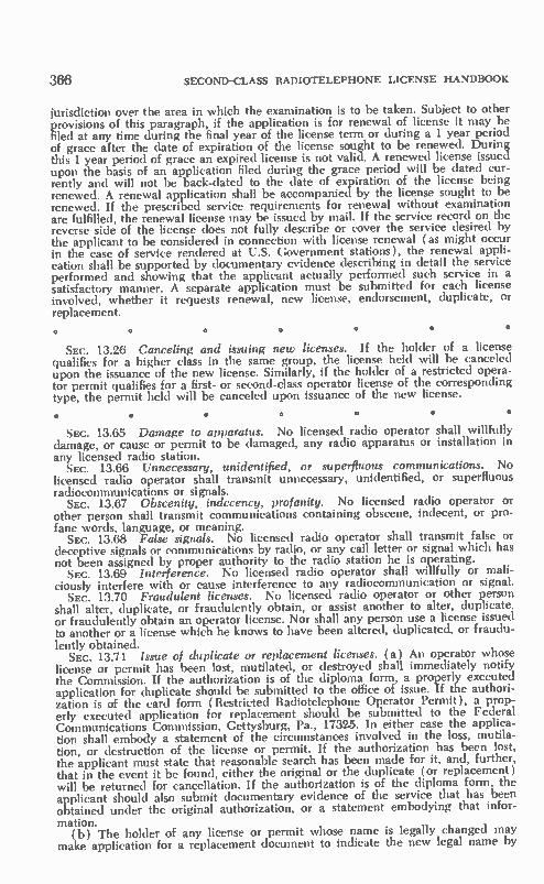
366 SECOND-CLASS RADIOTELEPHONE LICENSE HANDBOOK
jurisdiction over the area in which the examination is to be taken. Subject to other provisions of this paragraph, if the application is for renewal of license it may be filed at any time during the final year of the license term or during a 1 year period of grace after the date of expiration of the license sought to be renewed. During this 1 year period of grace an expired license is not valid. A renewed license issued upon the basis of an application filed during the grace period will be dated cur-rently and will not be back-dated to the date of expiration of the license being renewed. A renewal application shall be accompanied by the license sought to be renewed. If the prescribed service requirements for renewal without examination are fulfilled, the renewal license may be issued by mail. If the service record on the reverse side of the license does not fully describe or cover the service desired by the applicant to be considered in connection with license renewal (as might occur in the case of service rendered at U.S. Government stations), the renewal appli-cation shall be supported by documentary evidence describing in detail the service performed and showing that the applicant actually performed such service in a satisfactory manner. A separate application must be submitted for each license involved, whether it requests renewal, new license, endorsement, duplicate, or replacement. • • • • • • •
SEC. 13.26 Canceling and issuing new licenses. If the holder of a license qualifies for a higher class in the same group, the license held will be canceled upon the issuance of the new license. Similarly, if the holder of a restricted opera-tor permit qualifies for a first- or second-class operator license of the corresponding type, the permit held will be canceled upon issuance of the new license.
• • • • • •
Sec. 13.65 Damage to apparatus. No licensed radio operator shall willfully damage, or cause or permit to be damaged, any radio apparatus or installation in any licensed radio station. SEC. 13.66 Unnecessary, unidentified, or superfluous communications. No
licensed radio operator shall transmit unnecessary, unidentified, or superfluous radiocommunications or signals. SEC. 13.67 Obscenity, indecency, profanity. No licensed radio operator or
other person shall transmit communications containing obscene, indecent, or pro-fane words, language, or meaning. SEC. 13.68 False signals. No licensed radio operator shall transmit false or
deceptive signals or communications by radio, or any call letter or signal which has not been assigned by proper authority to the radio station he is operating. SEC. 13.69 Interference. No licensed radio operator shall willfully or mali-
ciously interfere with or cause interference to any radiocommunication or signal. SEC. 13.70 Fraudulent licenses. No licensed radio operator or other person
shall alter, duplicate, or fraudulently obtain, or assist another to alter, duplicate. or fraudulently obtain an operator license. Nor shall any person use a license issued to another or a license which he knows to have been altered, duplicated, or fraudu-lently obtained. SEC. 13.71 Issue of duplicate or replacement licenses. (a) An operator whose
license or permit has been lost, mutilated, or destroyed shall immediately notify the Commission. If the authorization is of the diploma form, a properly executed application for duplicate should be submitted to the office of issue. If the authori-zation is of the card form (Restricted Radiotelephone Operator Permit), a prop-erly executed application for replacement should be submitted to the Federal Communications Commission, Gettysburg, Pa., 17325. In either case the applica-tion shall embody a statement of the circumstances involved in the loss, mutila-tion, or destruction of the license or permit. If the authorization has been lost, the applicant must state that reasonable search has been made for it, and, further, that in the event it be found, either the original or the duplicate (or replacement) will be returned for cancellation. If the authorization is of the diploma form, the applicant should also submit documentary evidence of the service that has been obtained under the original authorization, or a statement embodying that infor-mation.
(b) The holder of any license or permit whose name is legally changed may make application for a replacement document to indicate the new legal name by

ADDITIONAL REFERENCE MATERIAL 367
submitting a properly executed application accompanied by the license or permit affected. If the authorization is of the diploma form, the application should be sub-mitted to the office where it was issued. If the authorization is of the card form (Restricted Radiotelephone Operator Permit) it should be submitted to the Federal Communications Commission, Gettysburg, Pa., 17325. SEC. 13.72 Exhibiting signed copy of application. When a duplicate or re-
placement operator license or permit has been requested, or request has been made for renewal upon service or for an endorsement or a vertification card, the operator shall exhibit in lieu of the original document a signed copy of the application which has been submitted by him. • • • • • •
SEC. 81.179 Message charges. (a) (1) No charge shall be made for the service of any public coast station unless effective tariffs applicable to such service are on file with the Commission, pursuant to the requirements of Section 203 of the Communications Act and Part 61 of this chapter.
(2) No charge shall be made for the service of any station subject to this part, other than a public cost station, except as provided by and in accordance with Section 81.352.
(b) No charge shall be made by any station in the maritime mobile service of the United States for the transmission of distress messages and replies thereto in connection with situations involving the safety of life and property at sea.
(c) No charge shall be made by any station in the maritime mobile service of the United States for the transmission, receipt, or relay of the information concern-ing dangers to navigation designated in Section 83.303 (b) of this chapter, orig-inating on a ship of the United States or of a foreign country. • • • •
SEC. 81.302 Points of communication. (a) Subject to the conditions and limitations imposed by the terms of the particular coast station license or by the applicable provisions of this part with respect to the use of particular radio-chan-nels, public coast stations using telephony are authorized to communicate: ( 1) With any ship station or aircraft station operating in the maritime mobile
service for the transmission or reception of safety communication; (2) With any land station for the purpose of facilitating the transmission or re-
ception of safety communication to or from a ship or aircraft station;— • • •
SEC. 83.6 Operational definitions. (f) Calling. Transmissions from a station solely to secure the attention of another station, for a particular purpose.
(g) Working. Radiocommunication carried on, for a purpose other than calling, by any station or stations using telegraphy, telephony or facsimile. SEC. 83.165 Posting of operator authorization. (a) Except as provided in
paragraph (b) of this section, when an operator is required for the operation of a station subject to this part, the original authorization of each such operator while he is employed or designated as radio operator of the station shall be posted in a conspicuous place at the principal location on board ship at which the station is operated.
(b) An operator who holds a Restricted Radiotelephone Operator Permit or a valid license verification card (FCC Form 758-F) attesting to the existence of a commercial radio operator license of the diploma type, may, in lieu of posting, have such permit or verification card in his personal possession immediately avail-able for inspecticn upon request by a Commission representative when operating the following:
(1) A station which is not required to be installed on the vessel by reason of statute or treaty to which the United States is a party;
(2) Any class of ship station when the operator is on board solely for the pur-pose of servicing the radio equipment;
(3) A station of a portable nature. SEC. 83.223 Watch on 2182 kHz. (a) Each ship station on board a ship
navigating the Great Lakes and licensed to transmit by telephony on one or more frequencies within the band 1600 to 3500 kHz shall, during its hours of service for telephony, maintain an efficient watch for the reception of class A3 and A3H emis-sions on the authorized carrier frequency 2182 kHz, whenever the station is not

368 SECOND-CLASS RADIOTELEPHONE LICENSE HANDBOOK
being used for transmission on that channel or for communication on other radio channels. (b) Except for stations on board vessels required by law to be fitted with radio-
telegraph equipment, each ship station (in addition to those ship stations specified in paragraph (a) of this section ) licensed to transmit by telephnoy on one or more frequencies within the band 1605 to 3500 kHz shall, during its hours of service for telephony, maintain an efficient watch for the reception of class A3 or A3H emission on the authorized carrier frequency 2182 kHz, whenever such station is not being used for transmission on that channel or for communication on other radio channels. When the ship station is in Region 1 or 3, such watch shall, insofar as is possible, be maintained at least twice each hour for three minutes commencing at x h. 00 and x h. 30, Greenwich mean time (G.M.T.). • • • • • • • SEC. 83.234 Distress signals. (a) The international radiotelegraph distress
signal consists of the group "three dots, three dashes, three dots" (... - - - ...), symbolized herein by SOS, transmitted as a single signal in which the dashes are slightly prolonged so as to be distinguished clearly from the dots.
(b) The international radiotelephone distress signal consists of the word MAY-DAY, pronounced as the French expression "m'adier".
(c) These distress signals indicate that a mobile station is threatened by grave and imminent danger and requests immediate assistance. • • • • • • • SEC. 83.238 Radiotelephone distress call and message transmission procedure.
(a) The radiotelephone distress procedure shall consist of: (1) The radiotelephone alarm signal (whenever possible); ( 2) The distress calls; (3) The distress message; (b) The radiotelephone distress transmissions shall be made slowly and dis-
tinctly, each word being clearly pronounced to facilitate transcription. (c) After the transmission by radiotelephony of its distress message, the mobile
station may be requested to transmit suitable signals followed by its call sign or name, to permit direction-finding stations to determine its position. This request may be repeated at frequent intervals if necessary.
(d) The distress message, preceded by the distress call, shall be repeated at intervals until an answer is received. The repetition shall be preceded by the ra-diotelephone alarm signal whenever possible.
(e) When the mobile station in distress receives no answer to a distress message transmitted on the distress frequency, the message may be repeated on any other available frequency on which attention might be attracted. SEC. 83.239 Acknowledgment of receipt of distress message. (a) Stations of
the maritime mobile service which receive a distress message from a mobile station which is, beyond any possible doubt, in their vicinity, shall immediately acknowl-edge receipt. However, in areas where reliable communication with one or more coast stations are practicable, ship stations may defer this acknowledgment for a short interval so that a coast station may acknowledge receipt.
(b) Stations of the maritime mobile service which receive a distress message from a mobile station which, beyond any possible doubt, is not in their vicinity, shall allow a short interval of time to elapse before acknowledging receipt of the message, in order to permit stations nearer to the mobile station in distress to acknowledge receipt without interference. SEC. 83.240 Form of acknowledgment. (a) The acknowledgment of receipt of
a distress message is transmitted, when radiotelegraphy is used, in the following form:
(1) The call sign of the station sending the distress message, sent three times; (2) The word DE; (3) The call sign of the station acknowledging receipt, sent three times; (4) The group ERR; ( 5) The distress signal SOS. (b) The acknowledgment of receipt of a distress message is transmitted, when
radiotelephony is used, in the following form: ( 1) The call sign or other identification of the station sending the distress mes-
sage, spoken three times;

ADDITIONAL REFERENCE MATERIAL 369
(2) The words THIS IS; ( 3 )The call sign or other identification of the station acknowledging receipt,
spoken three times; (4) The word RECEIVED; (5) The distress signal MAYDAY. SEC. 83.241 Information furnished by acknowledging station. (a) Every mo-
bile station which acknowledges receipt of a distress message shall, on the order of the matter of person responsible for the ship, aircraft, or other vehicle carrying such mobile station, transmit as soon as possible the following information in the order shown:
(1) Its name; (2) Its position, in the form prescribed in Sec. 83.236 (c); (3) The speed at which it is proceeding towards, and the approximate time it
will take to reach, the mobile station in distress. (b) Before sending this message, the station shall ensure that it will not inter-
fere with the emissions of other stations better situated to render immediate assistance to the station in distress. SEC. 83.242 Transmission of distress message by a station not itself in distress.
(a) A mobile station or a land station which learns that a mobile station is in distress shall transmit a distress message in any of the following cases:
(1) When the station in distress is not itself in a position to transmit the distress message;
(2) When the master or person responsible for the ship, aircraft, or other ve-hicle not in distress, or the person responsible for the land station, considers that further help is necessary;
(3) When, although not in a position to render assistance, it has heard a distress message which has not been acknowledged. When a mobile station transmits a distress message under these conditions, it shall take all necessary steps to notify the authorities who may be able to render assistance.
(b) The transmission of a distress message under the conditions prescribed in paragraph (a) of this section shall be made on either or both of the international distress frequencies (500 kHz radiotelegraph; 2182 kHz radiotelephone) or on any other available frequency on which attention might be attracted.
(c) The transmission of the distress message shall always be preceded by the call indicated below, which shall itself be preceded whenever possible by the radio-telegraph or radiotelephone alarm signal. This call consists of:
( 1) When radiotelegraphy is used: (i) The signal DDD SOS SOS SOS DDD; ( ii) The word DE. (iii) The call sign of the transmitting station, sent three times. (2) When radiotelephony is used: (i) The signal MAYDAY RELAY, spoken three times; (ii) The words THIS IS: (iii) The call sign or other identification of the transmitting station, spoken
three times.
(d) When the radiotelegraph alarm signal is used, an interval of two minutes shall be allowed, whenever this is considered necessary, before the transmission of the call mentioned in subparagraph ( e ) ( 1) of this section. SEC. 83.247 Urgency signals. (a) The urgency signal indicates that the calling
station has a very urgent message to transmit concerning the safety of a ship, air-craft, or other vehicle, or the safety of a person.
(c) In radiotelephony, the urgency signal consists of the word PAN, spoken three times and transmitted before the call.
Sec. 83.249 Safety signals. (a) The safety signal indicates that the station is about to transr bit a message concerning the safety of navigation or giving im-portant meteorological warnings.
(b) In radiotelegraphy, the safety signal consists of three repetitions of the group TTT, sent with the individual letters of each group, and the successive groups clearly separated from each other. It shall be sent before the call.
(c) In radiotelephony, the safety signal consists of the word SECURITY, spoken three times and t-ansmitted before the call.
(d) The safety signal and call shall be sent on one of the international distress

370 SECOND-CLASS RADIOTELEPHONE LICENSE HANDBOOK
frequencies (500 kHz radiotelegraph; 2182 kHz radiotelephone) or on the national distress frequency (156.8 MHz radiotelephone). However, stations which cannot transmit on a distress frequency may use any other available frequency on which attention might be attracted. • • • • • • •
SEC 83.352 Frequencies for use in distress. (a) The frequency 2182 kHz is the international distress frequency for radiotelephony. It shall be used for this purpose by ship, aircraft, and survival craft stations using frequencies in the author-ized bands between 1605 and 4000 kHz when requesting assistance from the mari-time services. SEC. 83.353 Frequencies for calling. (a) The international general radio-
radiotelephone calling frequency for the maritime mobile service is 2182 kHz. It may be used as a carrier frequency for this purpose by ship stations and aircraft stations operating in the maritime mobile service. • • • • • • •
SEC. 83.365 Procedure in testing. (a) Ship stations must use every precaution to insure that, when conducting operational transmitter tests, the emissions of the station will not cause harmful interference. Radiation must be reduced to the lowest practicable value and if feasible shall be entirely suppressed. When radia-tion is necessary or unavoidable, the testing procedure described below shall be followed: ( 1) The licensed radio operator or other person responsible for operation of the
transmitting apparatus shall ascertain by careful listening that the test emissions will not be likely to interfere with transmissions in progress; if they are likely to interfere with the working of a coast or aeronautical station in the vicinity of the ship station, the consent of the former station( s ) must be obtained before the test emissions occur; (see required procedures in subparagraphs (2) and (3) of this paragraph following);
(2,) The applicable identification of the testing station, followed by the word "test" shall be announced on the radio-channel being used for the test, as a warn-ing that test emissions are about to be made on that frequency;
(3) If, as a result of the announcement prescribed in subparagraph (2) of this paragraph, any station transmits by voice the word "wait, testing shall be sus-pended. When, after an appropriate interval of time such announcement is re-peated and no response is observed, and careful listening indicates that harmful interference should not be caused, the operator shall, if further testing is necessary, proceed as set forth in subparagraphs (4) and (5) of this paragraph;
(4) Testing of transmitters shall, insofar as practicable be confined to working frequencies without two way communications; however, 2182 kHz and 156.8 MHz may be used to contact other ship or coast stations when signal reports are necessary. U.S. Coast Guard stations may be contacted on 2182 kHz for test pur-poses only when tests are being conducted during inspections by Commission representatives or when qualified radio technicians are installing equipment or correcting deficiencies in the station radiotelephone equipment. In these cases the test shall be identified as "FCC" or "technical" and logged accordingly;
(5) When further testing is necessary beyond the two "test" announcements specified in subparagraphs (2) and (3) of this paragraph, the operator shall an-nounce the word "testing" followed in the case of a voice transmission test by the count "1, 2, 3, 4, etc." or by test phrases or sentences not in conflict with normal operating signals. The test signals in either case shall have a duration not exceeding 10 seconds. At the conclusion of the test, there shall be voice an-nouncements of the official call sign of the testing station. This test transmission shall not be repeated until a period of at least 1 minute has elapsed; on the fre-quency 2182 kHz or 156.8 MHz a period of at least 5 minutes shall elapse before the test transmission is repeated.
(b) When testing is conducted on any frequency within the bands 2173.5 to 2190 kHz, 156.75 to 156.85 MHz, 480 to 510 kHz (survival craft transmitters only), or 8362 to 8366 kHz (survival craft transmitters only), no test transmissions shall occur which are likely to actuate any automatic alarm receiver within range. Survival craft stations shall not be tested on the frequency 500 kHz during the 500 kHz silence periods.

ADDITIONAL REFERENCE MATERIAL 371
SEC. 83.366 General radiotelephone operating procedure. (a) Calling coast stations. (1) Use by ship stations of the frequency 2182 kHz for calling coast sta-tions, and for replying to calls from coast stations, is authorized; however, when-ever practicable such calls and replies shall be made on the appropriate ship-shore working frequency.
(2) Use by ship stations and marine utility stations on board ship of the fre-quency 156.8 MHz for calling coast stations and marine utility stations on shore, and for replying to calls from such stations, is authorized; however, whenever practicable such calls and replies shall be made on the appropriate ship-shore working frequency.
(b) Calling ship stations. (1) Except when other operating procedure is used to expedite safety communication, ship stations, before transmitting on the inter-ship working frequencies 2003, 2142, 2638, 2738, or 2830 kHz, shall first establish communication with other ship stations by call and reply on 2182 kHz: Provided, That calls may be initiated on an intership working frequency when it is known that the called vessel maintains a simultaneous watch on such working frequency and on 2182 kHz.
(2) Except when other operating procedure is used to expedite safety com-munication, the frequency 156.8 MHz shall be used for call and reply by ship stations and marine utility stations on board ship before establishing communica-tion on either of the intership working frequencies 156.3 or 156.4 MHz.
(c) Change to working frequency. After establishing communication with an-other station by call and reply on 2182 kHz or 156.8 MHz, stations on board ship shall change to an authorized working frequency for the transmission of messages which, under the provisions of this subpart, cannot be transmitted on the respective calling frequencies.
(d) Authorized use of 2003, 2142, 2638, 2738, and 2830 kHz. The intership working frequencies 2003, 2142, 2638, 2738, and 2830 kHz shall be used for trans-missions by ship stations in accordance with the provisions of Secs. 83.176, 83.177, and 83.358.
(e) Simplex operation only. All transmission on 2003, 2142, 2638, 2738, and 2830 kHz by two or more stations, engaged in any one exchange of signals or communications, shall take place on only one of these frequencies, i.e., the stations involved shall transmit and receive on the same frequency: Provided, That this re-quirement is waived in the event of emergency when by reason of interference or interference or limitation of equipment single frequency operation cannot be used.
(f) Limitation on duration of calling. Calling a particular station shall not con-tinue for more than 30 seconds in each instance. If the called station is not heard to reply, that station shall not again be called until after an interval of 2 minutes. When a station called does not reply to a call sent three times at intervals of 2 minutes, the calling shall cease and shall not be renewed until after an interval of 15 minutes; however, if there is no reason to believe that harmful interference will be caused to other communications in progress, the call sent three times at inter-vals of 2 minutes may be repeated after a pause of not less than 3 minutes. In event of an emergency involving safety, the provisions of this paragraph shall not apply.
(g) Limitation on duration of working. Any one exchange of communications between any two ship stations on 2003, 2142, 2638, 2738, or 2830 kHz, or be-tween a ship station and a limited coast station on 2738 or 2830 kHz, shall not exceed 3 minutes in duration after the two stations have established contact by calling and answering. Subsequent to such exchange of communications, the saine two stations shall not again use 2003, 2142, 2638, 2738, or 2830 kHz for com-munication with each other until 10 minutes have elapsed: Provided, That this provision shall ih no way limit or delay the transmission of communications con-cerning the safety of life or property.
(h) Transmission limitation on 2182 kHz and 156.8 MHz. Any one exchange of signals by ship stations on 2182 kHz or 156.8 MHz (including calls, replies thereto, and operating signals) shall not exceed 2 minutes Provided, That this time limita-tion is not applicable to the transmission of distress, alarm, urgency, or safety sig-nals, or to messages preceded by one of these signals.
(i) Limitation on commercial communication. On frequencies in the band 156-162 MHz, the exchange of commercial communication shall be limited to the mini-mum practicable transmission time. In the conduct of ship-shore communication.

372 SECOND-CLASS RADIOTELEPHONE LICENSE HANDBOOK
other than distress, stations on board ship shall comply with instructions given by the limited coast station or marine utility station on shore with which they are communicating, in all matters relative to operating practices and procedures and to the suspension of transmission in order to minimize interference.
(j) 2182 kHz silence periods in Regions 1 and 3. Transmission by ship or sur-vival craft stations when in Regions 1 and 3 (except in the territorial waters of Japan and the Philippines) is prohibited on any frequency (including 2182 kHz within the band 2173.5 to 2190.5 kHz during each 2182 kHz silence period, i.e., for 3 minutes twice each hour beginning at x h. 00 and x h. 30. Greenwich mean time: Provided, however, That this provision is not applicable to the transmission of distress, alarm, urgency, or safety signals, or to messages preceded by one of these signals.

APPENDIX V
Reference Material for Element Ill Study
GENERAL RULES AND REGULATIONS
SEC. 2.101 Nomenclature of frequencies.
Frequency Band No. Frequency Subdivision Range
4 vlf (very low frequency) Below 30 kHz. 5 If (low frequency) 30 to 300 kHz. 6 mf (medium frequency) 300 to 3000 kHz. 7 hi (high frequency) 3 to 30 MHz. 8 vhf (very high frequency) 30 to 300 MHz. 9 uhf (ultrahigh frequency) 300 to 3000 MHz. 10 shf (superhigh frequency) 3 to 30 CHz. 11 ehf (extremely high frequency) 30 to 300 CHz. • • • • • • o
SEC. 2.201 Emission, modulation, and transmission characteristics. The fol-lowing system of designating emission, modulation and transmission characteristics shall be employed.
(a) Emissions are designated according to their classification and their necces-sary bandwidth.
(b) Emissions are classified and symbolized according to the following charac-teristics.
(1) Type of modulation of main carrier. (2) Type of transmission. (3) Supplementary characteristics. (c) Types of modulation of main carrier:
symbol (1) Amplitude A (2) Frequency (or Phase) (3) Pulse
(d) Types of transmission: (1) Absence of any modulation intended to carry information 0 (2) Telegraphy without the use of a modulating audio frequency 1 (3) Telegraphy by the on-off keying of a modulating audio frequency or
audio frequencies, or by the on-off keying of the modulated emission (special case: an unkeyed modulated emission) 2
(4) Telephony (including sound broadcasting) 3 (5) Facsimile (with modulation of main carrier either directly or by a fre-
quency modulated subcarrier) 4 (6) Television (visual only) 5
373

Type of Modulation of Main Carrier Type of Transmission Supplementary Characteristics Symbol
Amplitude modulation
With no modulation Telegraphy without the use of a modulating audio
frequency (by on-off keying). Telegraphy by the on-off keying of an amplitude
modulating audio frequency or audio frequencies, or by the on-off keying of the modulated emis-sion (special case: an unkeyed emission amplitude modulated).
Telephony
Facsimile (with modulation of main carrier either directly or by a frequency modulated subcarrier)
Facsimile Television Multichannel voice-frequency telegraphy Cases not covered by the above, e.g., a combination
of telephony and telegraphy.
Double sideband Single sideband, reduced carrier Single sideband, full carrier Single sideband, suppressed carrier Two independent sidebands
Single sideband, reduced carrier Vestigial sideband Single sideband, reduced carrier Two independent sidebands
AO Al
A2
A3 A3A A3H A3J A38 A4
A4A A5C A7A A9B
Frequency (or phase) modulation
Telegraphy by frequency shift keying w;thout the use of a modulating audio frequency: one of two frequencies being emitted at any instant.
Telegraphy by the on-off keying of a frequency modulating audio frequency or by the on-off key-ing of a frequency modulated emission (special case: an unkeyed emission, frequency modulated),
Telephony Facsimile by direct frequency modulation of the
carrier.
F I
F2
F3 F4
SECOND-CLASS RADIOTELEPHONE LICENSE
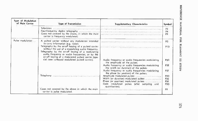
Type of Modulation of Main Carrier Type of Transmission Supplementary Characteristics Symbol
Television Four-frequency diplex telegraphy Cases not covered by the above, in which the main
carrier is frequency modulated.
F5 F6 F9
Pulse modulation .. A pulsed carrier without any modulation intended to carry information (e.g. radar).
Telegraphy by the on-off keying of a pulsed carrier without the use of a modulating audio frequency.
Telegraphy by the on-off keying of a modulating audio frequency or audio frequencies, or by the on-off keying of a modulated pulsed carrier (spe-cial case: unkeyed modulated pulsed carrier).
Telephony
Cases not covered by the above in which the main carrier is pulse modulated.
Audio frequency or audio frequencies modulating the amplitude of the pulses.
Audio frequency or audio frequencies modulating the width (or duration) of the pulses.
Audio frequency or audio frequencies modulating the phase (or position) of the pulses.
Amplitude modulated pulses Width (or duration) modulated pulses Phase (or position) modulated pulses Code modulated pulses (after sampling and
quantization).
PO
P1 D
P2D
P2E
P2F
P3D P3E P3F P3G
P9
Z.J I

376 SECOND-CLASS RADIOTELEPHONE LICENSE HANDBOOK
(7) Four-frequency diplex telegraphy 6 (8) Multichannel voice-frequency telegraphy 7 (9) Cases not covered by the above 9
(e) Supplementary characteristics: (1) Double sideband (None) (2) Single sideband:
(i) Reduced carrier A (ii) Full carrier H (iii) Suppressed carrier
(3) Two independent sidebands (4) Vestigial sideband
(i) Amplitude modulated D (ii) Width ( or duration) modulated E (iii) Phase (or position) modulated (iv) Code modulated G
( f) The classification of typical emissions is tabulated on page 326 and page 327. (g) Type B emission: As an exception to the above principles, damped waves
are symbolized in the Commission's rules and regulations as type B emission. (h) Whenever the full designation of an emission is necessary, the symbol for
that emission, as given above, shall be preceded by a number indicating in kilo-hertz the necessary bandwidth of the emission. Bandwidths shall generally be expressed to a maximum of three significant figures, the third figure being almost always a nought or a five. • • • • • •
SEC. 2.202 Bandwidths. (a) Occupied bandwidth: The frequency bandwidth such that, below its lower and above its upper frequency limits, the mean powers radiated are each equal to 0.5 percent of the total mean power radiated by a given emission. In some cases, for example multichannel frequency-division sys-tems, the percentage of 0.5 percent may lead to certain difficulties in the practical application of the definitions of occupied and necessary bandwidth; in such cases a different percentage may prove useful.
(b) Necessary bandwidth: For a given class of emission, the minimum value of the occupied bandwidth sufficient to ensure the transmission of information at the rate and with the quality required for the system employed, under specified con-ditions. Emissions useful for the good functioning of the receiving equipment as, for example, the emission corresponding to the carrier of reduced carrier systems, shall be included in the necessary bandwidth.
(e) The necessary bandwidth may be determined by one of the following methods:
(1) Use of the formulas included in the following Table which also gives ex-amples of necessary bandwidths and designation of corresponding emissions;
(2) Computation in accordance with Recommendations of the International Radio Consultative Committee (C.C.I.R.);
(3) Measurement, in cases not covered by subparagraphs (1) and (2) of this paragraph.
(d) The value so determined should be used when the full designation of an emission is required. However, the necessary bandwidth so determined is not the only characteristic of an emission to be considered in evaluating the interference that may be caused by that emission.
(e) In the formulation of the table, the following terms have been employed: B. = Necessary bandwidth in hertz. B = Telegraph speed in bauds. N = Maximum possible number of black plus white elements to be transmitted
per second, in facsimile and television. M = Maximum modulation frequency in hertz. C = Subcarrier frequency in hertz. D = Half the difference between the maximum and minimum values of the in-
stantaneous frequency. Instantaneous frequency is the rate of change of phase.
t = Pulse duration in seconds. K = An overall numerical factor which varies according to the emission and
which depends upon the allowable signal distortion.

I. AMPLITUDE MODULATION
Description and Class of Emission Necessary Bandwidth in Hertz
Examples
Details Designation of Emission
Continuous wave telegraphy, Al.
B. = BK K = 5 for fading circuits. K = 3 for nonfading circuits.
Morse code at 25 words per minute, B = 20, K = 5. Bandwidth: 100 Hz. Four-channel time-division multiplex, 7-unit code, 42.5
bands per channel, B = 170, K = 5. Bandwidth: 850 Hz.
0.1A 1
0.85A1
Telegraphy modulated by an audio f re- quency, A2.
B. = BK -I- 2M K = 5 for fading circuits. K = 3 for nonfading circuits.
Morse code at 25 words per minute, B = 20, M .=- 1000, K = 5.
Bandwidth: 2000 Hz.
2.1A2
Telephony, A3. B. = M for single sideband.
B. = 2M for double sideband.
Double sideband telephony M = 3000. Bandwidth: 6000 Hz. Single sideband telephony reduced carrier, M = 3000. Bandwidth: 3000 Hz. Telephony, two independent sidebands, M = 3000. Bandwidth: 6000 Hz.
6A3
3A3A
6A3B
Sound broadcasting, A3.
B,, = 2M M may vary between 4000 and 10,000
depending on quality desired.
Speech and music, M = 4000.
Bandwidth: 8000 Hz.
8A3
Facsimile, carrier modulated by tone and by keying, A4.
B. = KN + 2M K = 1.5
The total number of picture elements (black plus white) transmitted per second is equal to the circumference of the cylinder multiplied by the number of lines per unit length and by the speed of rotation of the cylin-der in revolutions per second.
Diameter of cylinder = 70 mm. Number of lines per mm = 5. Speed of rotation -= 1 r.p.s. N = 1100. M = 1900. Bandwidth: 5450 Hz.
5.45A4

378 SECOND-CLASS RADIOTELEPHONE LICENSE HANDBOOK
SEC. 2.551 Program defined. In order to carry out its responsibilities under the Communications Act and the various treaties and international regulations, it is necessary for the Commission to ascertain that the equipment involved is capable of meeting the technical operating standards set forth in said statutes, treaties and the Commission's rules and regulations. To facilitate such determi-nations in those services where equipment is generally standardized, to _promote the improvement of equipment and to promote the efficient use of the radio' spec-trum, the Commission has designed two specific procedures for securing advance approval of equipment. These procedures are designed as type approval and type acceptance. Ordinarily, type approval contemplates tests conducted by Commis-sion personnel, while type acceptance is based on data concerning the equipment submitted by the manufacturer or the individual prospective licensee. The pro-cedures described in this subpart are intended to apply to equipment in those services which specifically require either type approval or type acceptance. These procedures may also be applied to equipment components, such as radio frequency power amplifiers, etc., to the extent specified in the rules of the particular service in which such components will be used.
PUBLIC SAFETY RADIO SERVICE
SEC. 89.1 Basis and purpose. (a) The basis for this part is the Communica-lions Act of 1934, as amended, and applicable treaties and agreements to which the United States is a party. This part is issued pursuant to authority contained in Title III of the Communications Act of 1934, as amended, which vests authority in the Federal Communications Commission to regulate radio transmissions and to issue licenses for radio stations.
(b) This part is designed to provide a service of radiocommunication essential either to the discharge of non-Federal governmental functions or to the alleviation of an emergency endangering life or property. • • • • • • SEC. 89.3 Definitions. For the purpose of this part the following definitions
shall be applicable. (For other definitions, refer to Part 2 of this chapter): (a) Definitions of services: Fire Radio Service. A public safety service of radiocommunication essential to
official fire activities. Fixed service. A service of radiocommunication between specified fixed points.
Forestry-Conservation Radio Service. A public safety device of radiocommuni-cation essential to forestry-conservation activities. 'Highway Maintenance Radio Service. A public safety service of radiocommu-
nication essential to official highway activities. Land mobile service. A mobile service between base stations and land mobile
stations, or between land mobile stations. Local Government Radio Service. A service of radiocommunication essential
to official activities of states, possessions, and territories, including counties, towns, cities, and similar governmental subdivisions.
Mobile service. A service of radiocommunication between mobile and land sta-tions, or between mobile stations.
Police Radio Service. A public safety service of radiocommunication essential to official police activities.
Public safety radio services. Any service of radiocommunication essential either to the discharge of non-Federal government functions or the alleviation of an emergency endangering life or property, the radio transmission facilities of which are defined as fixed, land, mobile, or radiolocation stations.
Radiolocation. Radiodetermination used for purposes other than those of radio-navigation. (For the purposes of this part, radiolocation will include speed mea-suring devices.)

REFERENCE MATERIAL FOR ELEMENT III STUDY 379
Radio service. An administrative subdivision of the field of radiocommunication. In an engineering sense the subdivisions may be made according to the method of operation; as for example, mobile service and fixed service. In a regulatory sense, the subdivisions may be descriptive of particular groups of licensees; as for ex-ample, the groups and subgroups of persons licensed under this part.
Safety Service. A radiocommunication service used permanently or temporarily for the safeguarding of human life and property.
Special Emergency Radio Service. A public safety service of radiocommunica-tion essential to the alleviation of an emergency endangering life or property.
State Guard Radio Service. A public safety service of radiocommunication es-sential to official activities of state guards or comparable organizations of states, territories, possessions, or the District of Columbia.
(b) Definitions of stations: Base station. A land station in the land mobile service carrying on a service with
land mobile stations.
Control station. An operational fixed station, the transmissions of which are used to control, automatically, the emissions or operation of another radio station at a specified location.
Fixed station. A station in the fixed service.
Fixed relay station. An operational fixed station established for the automatic retransmission of radiocommunications received from either one or more fixed stations or from a combination of fixed and mobile stations and directed to a speci-fied location.
Interzone station. A fixed station in the Police Radio Service using radioteleg-raphy (Al emission) for communication with zone stations within the zone and with interzone stations in other zones.
Land station. A station in the mobile service not intended to be used while in motion.
Mobile station. A station in the mobile service intended to be used while in motion or during halts at unspecified points.
Mobile relay station. A base station established for the automatic retransmission of mobile service communications which originate on the transmitting frequency of the mobile stations and which are retransmitted on the receiving frequency of the mobile stations.
Operational fixed station. A fixed station, not open to public correspondence, operated by and for the sole use of those agencies operating their own radiocom-munication facilities in the Public Safety, Industrial, Land Transportation, Marine, or Aviation Services.
Radiolocation mobile station. A station in the radiolocation service intended to be used while in motion or during halts at unspecified points.
Repeater station. An operational fixed station established for the automatic re-transmission of radiocommunications received from any station in the Mobile Service.
Zone station. A fixed station in the Police Radio Service using radiotelegraphy (Al emission) for communication with other similar stations in the same zone and with an interzone station. ( c ) Miscellaneous definitions: Antenna height above average terrain (AAT). The average of the antenna heights
above the terrain from 2 to 10 miles from the antenna for eight directions spaced evenly for each 45° of azimuth starting with true north. In general, a different antenna height will be determined in each direction from the antenna. The average of these various heights is considered the antenna height above average terrain.
Antenna power gain. The square of the ratio of the root-mean-square free space field intensity produced at 1 mile in the horizontal plane, in millivolts per meter for 1 kilowatt antenna input power to 137.6 mV/m. This ratio should be expressed

380 SECOND-CLASS RADIOTELEPHONE LICENSE HANDBOOK
in decibels (dB). (If specified for a particular direction, antenna power gain is based on the field strength in that direction only.)
Antenna structures. The term "antenna structure' includes the radiating system, its supporting structures, and any surmounting appurtenances.
Assigned frequency. The frequency appearing on a station authorization from which the carrier frequency may deviate by an amount not to exceed that per-mitted by the frequency tolerance.
Authorized bandwidth. The maximum width of the band of frequencies, as specified in the authorizations, to be occupied by an emission. Bandwidth occupied by an emission. The width of the frequency band (nor-
mally specified in kilohertz) containing those frequencies upon which a total of 99 percent of the radiated power appears, extended to include any discrete fre-quency upon which the power is at least 0.25 percent of the total radiated power.
Carrier frequency. The frequency of the carrier.
Effective radiated power (ERP). The product of the antenna input power and the antenna power gain. This product should be expressed in watts. (If specified in a particular direction, effective radiated power is based on the antenna power gain in that direction only.)
Harmful interference. Any emission, radiation or induction which endangers the functioning of a radionavigation service or of other safety services or seriously degrades, obstructs or repeatedly interrupts a radiocommunication service operat-ing in accordance with this chapter.
Landing area. A landing area means any locality, either land or water, which is used, or intended to be used, for the landing and take-off of aircraft whether or not facilities are provided for shelter, servicing, or repair of aircraft, or for receiv-ing or discharging passengers or cargo.
Station authorization. Any construction permit, license, or special temporary authorization issued by the Commission. • o • •
SEC. 89.51 Station authorization required. No radio transmitter shall be op-erated in the Public Safety Radio Services except under and in accordance with a proper station authorization granted by the Federal Communication Commission. • • o • o 0 •
SEC. 89.53 Procedure for obtaining a radio station authorization and for com-mencement of operation. (a) Persons desiring to install and operate radio trans-mitting equipment should first submit an application for a radio station authoriza-tion in accordance with Section 89.59 (a).
(b) When construction permit only has been issued for a base, fixed, or mobile station and installation has been completed in accordance with the terms of the construction permit and the applicable rules of the Commission, the permittee shall proceed further as follows:
(1) Notify the Engineer in Charge of the local radio district of the date on which the transmitter will first be tested in such a manner as to produce radiation, giving name of the permittee, station location, call sign, and frequencies on which tests are to be conducted. This notification shall be made in writing at least two days in advance of the test date. FCC Form 456 may be used for this purpose. No reply from the radio district office is necessary before the tests are begun.
(2) After testing, but on or before the date the station is used for operational purposes, mail to the Commission in Washington, D.C. 20554, an application on FCC Form 400 or in the case of microwave station on FCC Form 402 for license or modification of license as appropriate in the particular case. The station may thereafter be used as though licensed, pending Commission action on the license application.
(c) When a construction permit and license for a new base, fixed, or mobile station are issued simultaneously, the licensee shall notify the Engineer in Charge of the local radio district of the date on which the transmitter will be placed in operation, giving name of licensee, station location, call sign, and operating fre-

REFERENCE MATERIAL FOR ELEMENT LII STUDY 381
quencies. This notification shall be macle in writing on or before the day on which operation is commenced. FCC Form 456 may be used for this purpose.
(d) When a construction permit and modification of license for a base, fixed, or mobile station are issued simultaneously, operation may be commenced without notification to the Engineer in Charge of the local radio district, except where operation on a new or different frequency results by reason of such modification, in which event the notification procedure set forth in paragraph (c) of this section must be observed. •
SEC. 89.55 Filing of applications. (a) To assure that necessary information is supplied in a consistent manner by all persons, standard forms are prescribed for use in connection with the majority of applications and reports submitted for Commission consideration. Standard numbered forms applicable to the Public Safety Radio Services are discussed in Section 89.59, and may be obtained from the Washington, D.C. 20554, office of the Commission, or from any of its engi-neering offices. Concerning matters where no standard form is applicable, the pro-cedure outlined in Section 89.61 should be followed. ( b) Except for applicants in the Chicago, Ill., Regional Area filing on FCC Form
425, any application for radio station authorization and all correspondence relating thereto shall be submitted to the Commission's office at Washington, D.C. 20554, directed to the attention of the Secretary. Applicants for base, mobile and fixed stations to operate on frequencies below 950 MHz in the Chicago Region shall file FCC Form 425 at the Commission's Washington, D.C. office, until January 1, 1973; after January 1, 1973, the form is to be filed at the Commission's Chicago Regional Office. An application for commercial radio operator permit or license may be submitted to any of the Commission's engineering field offices, or to the Commis-sion's office at Washington, D.C. 20554.
(c) Unless otherwise specified, an application shall be filed at least 60 days prior to the date on which it is desired that Commission action thereon be com-pleted. In particular, applications involving the installation of new equipment shall be filed at least 60 days prior to the contemplated installation.
((I) Failure on the part of the applicant to provide all the information required by the application form or to supply the necessary exhibits or supplementary state-ments may constitute a defect in the application.
(e) Applications involving operation at temporary locations: (1) When one or more individual transmitters are intended to be operated as
a base station or as a fixed station at unspecified or temporary locations for inde-terminate periods, such transmitters may be considered to comprise a single sta-tion intended to be operated at temporary locations. An application for authority to operate a base station or a fixed station at temporary locations shall specify the general geographic area within which the operation will be confined. The area specified may be a city, a county or counties, or a state or states.
(2) When a base station or fixed station authorized to operate at temporary locations remains at a single location for more than one year, an application for modification of the station authorization to specify the permanent location shall be filed within 30 days after expiration of the 1 year period. • • • •
SEC. 89.57 Who may sign applications. (a) Except as provided in paragraph (b) of this section, applications, amendments thereto, and related statements of fact required by the Commission shall be personally signed by the applicant, if the applicant is an individual; by one of the partners, if the applicant is a part-nership; by an officer, if the applicant is a corporation; or by a member who is an officer, if the applicant is an unincorporated association. Applications, amendments, and related statements of fact filed on behalf of eligible government entities, such as states and territories of the United States and political subdivisions thereof, the District of Columbia, and units of local government, including incorporated munic-ipalities, shall be signed by such duly elected or appointed officials as may be com-petent to do so under the laws of the applicable jurisdiction.
(b) Applications, amendments thereto, and related statements of fact required by the Commission may be signed by the applicant's attorney in case of the applicant's physical disability or of his absence from the United States. The at-
382 SECOND-CLASS RADIOTELEPHONE LICENSE HANDBOOK
torney shall in that event separately set forth the reason why the application is not signed by the applicant. In addition, if any matter is stated on the basis of the attorney's belief only (rather than his knowledge), he shall separately set forth his reasons for believing that such statements are true.
(c) Only the original of applications, amendments, or related statements of fact, need be signed; copies may be conformed.
(d) Applications, amendments, and related statements of fact need not be signed under oath. Willful false statements made therein, however, are punishable by fine and imprisonment, U.S. Code, Title 18, section 1001, and by appropriate administrative sanctions, including revocation of station license pursuant to section 312( a) ( 1 ) of the Communications Act of 1934, as amended.
•
SEC. 89.59 Standard forms to be used. (a) Except as provided in Sec. 89.60 and paragraph (h) of this section, a separate application shall be submitted on FCC Form 400 for the following:
(1) New station authorization for a base or fixed station. (2) New station authorization for any required number of mobile units (in-
cluding hand-carried or pack-carried units) or any required number of units of a base station or fixed station to be operated at temporary locations in the same service.
NOTE: An application for mobile units may be combined with an application for a single base station in those cases where the mobile units will operate with that base station in a single radiocommunication system. (3) License for any class of station upon completion of construction or installa-
tion in accordance with the terms and conditions set forth in the construction permit.
(4) Modification of combined construction permit and station license for changes outlined in Section 89.75 (a).
(5) Modification of construction permit. (6) Modification of station license. Any of the foregoing applications will, upon approval and authentication of
the Commission, be returned to the applicant as a specifically designated type of authorization.
(b) When the holder of a station authorization desires to assign to another person the privilege to construct or use a radio station, he shall submit to the Commission a letter setting forth his desire to assign all right, title, and interest in and to such authorization, stating the call sign and location of station. This letter shall also include a statement that the assignor will submit his current station au-thorization for cancellation upon completion of the assignment. Enclosed with this letter shall be an application for Assignment of Authorization on FCC Form 400 prepared by and in the name of the person to whom the stations is being as-signed.
(c) [Reserved] (d) A separate application shall be submitted on FCC Form 703 whenever it
is proposed to change, as by transfer of stock-ownership, the control of a corporate permittee or licensee.
(e) An application not submitted on a standard form prescribed by the Com-mission is considered to be an informal application. Each informal application shall be submitted in duplicate, normally in letter form, and with the original properly signed. Each application shall be clear and complete within itself as to the facts presented and the action desired.
(f) FCC Form 456 "Notification of Completion of Radio Station Construction" may be used to advise the Engineer-in-Charge of the local district office that con-struction of the station is complete and that operational tests will begin.
(g) Application for renewal of station license shall be submitted on FCC Form 405-A. All applications for renewal must be made during the license term and should be filed within 90 days but not later than 30 days prior to the end of the license term. In any case in which the licensee has, in accordance with the pro-visions of this chapter, made timely and sufficient application for renewal of license, no license with reference to any activity of a continuing nature shall ex-pire until such application shall have been finally determined.

REFERENCE MATERIAL FOR ELEMENT III STUDY 383
(h) Application for construction permit, license, modification or assignment thereof for an operational fixed station using frequencies above 952 MHz (a so-called microwave 3tation) shall be submitted on FCC Form 402.
o SEC. 89.75 Changes in authorized stations. Authority for certain changes in
authorized stations must be obtained from the Commission before these changes are made, while other changes do not require prior Commission approval. The following paragraphs describe the conditions under which prior Commission ap-proval is or is not necessary.
(a) Proposed changes which will result in operation inconsistent with any of the terms of the current authorization require that an application for modification of construction permit and/or license be submitted to the Commission and shall be submitted on FCC Form 400, or, in the case of microwave stations, on FCC Form 402, and shall be accompanied by exhibits and supplementary statements as required by Section 89.63.
(b) [Reserved] (c) Proposed changes which will not depart from any of the terms of the out-
standing authorization for the station involved may be made without prior Com-mission approval. Included in such changes is the substitution of various makes of transmitting equipment at any station provided the particular equipment to be installed is included in the Commission s "List of Equipment Acceptable for Licensing" and designated for use in the Public Safety, Industrial, and Land Transportation Radio Services and provided the substitute equipment employs the same type of einissinn and does not exceed the power limitations as set forth in the station authorization.
(d) When the name of a licensee is changed (without changes in the ownership, control, or corporate structure), or when the mailing address is changed (without changing the authorized location of the base or fixed station or the area of opera-tion of mobile stations) a formal application for modification of license is not re-quired. However, the licensee shall notify the Commission promptly of these changes. The notice, which may be in letter form, shall contain the naine and ad-dress of the licensee as they appear in the Commission's records, the new name and/or address, as the case may be, the call signs and classes of all radio stations authorized to the licensee under this part and the radio service in which each station is authorized. The notice shall be sent to (1) Secretary, Federal Communi-cations Commission, Washington, D.C. 20554, and (2) the Engineer in Charge of the radio district in which the station is located, and a copy shall be main-tained with the license of each station until a new license is issued.
e O O e SEC. 89.103 Frequency stability. (a) A permittee or licensee in these services
shall maintain the carrier frequency of each authorized transmitter within the following percentage of the assigned frequency:
All Fixed All Mobile Stations and Base Over 3 Watts
Frequency Range Stations 3 Watts or Less
MHz Percent Percent Percent Below 25 0.01 0.01 0.02 25 to 50 ......... . .002 .002 .005 50 to 450 .0005 .0005 .005 450 to 470 .00025 .0005 .0005 470 to 512 .00025 .0005 .005 Above 950 (z) (z) ()
' To be specified in the station authorization.
(b) For the purpose of determining the frequency tolerance applicable to a particular transmitter in accordance with the foregoing provisions of this section,

384 SECOND-CLASS RADIOTELEPHONE LICENSE HANDBOOK
the power of a transmitter shall be the maximum rated plate power input to its final radio frequency stage, as specified by the manufacturer. • • • • • • •
SEC. 89.107 Emission limitations. (a) Each authorization issued to a station operating in these services will show, as a prefix to the emission classification, a figure specifying the maximum authorized bandwidth in kilohertz to be occupied by the emission. The specified band shall contain those frequencies upon which a total of 99 percent of the radiated power appears, extended to include any discrete frequency upon which the power is at least 0.25 percent of the total radiated power. Any radiation in excess of the limits specified in paragraph (c) of this section is considered to be an unauthorized emission.
(b) The maximum authorized bandwidth of emission corresponding to the types of emission specified in Section 89.105 (a) and (c), and the maximum authorized frequency deviation in the case of frequency or phase modulated emission, shall be as follows:
(1) For all type A3 emissions, the maximum authorized bandwidth shall be 8 kHz.
(2) For all F3 emission, the maximum authorized bandwidth and maximum authorized frequency deviation shall be as follows:
Frequency Band (MHz)
25 to 50 50 to 150 150 to 450 450 to 470 470 to 512
Authorized Bandwidth
(kHz)
20 20 20 20 20
Frequency Deviation
(kHz)
5
5
5
(3) For all type Al emissions, the maximum authorized bandwidth shall be 0.25 kHz.
(c) The mean power of emissions shall be attenuated below the mean output power of the transmitter in accordance with the following schedule:
(1) On any frequency removed from the assigned frequency by more than 50 percent up to and including 100 percent of the authorized bandwidths: At least 25 decibels.
(2) On any frequency removed from the assigned frequency by more than 100 percent up to and including 250 percent of the authorized bandwidth: At least 35 decibels.
(3) On any frequency removed from the assigned frequency by more than 250 percent of the authorized bandwidth: At least 43 plus 10 Log. (mean output power in watts) decibels or 80 decibels, whichever is the lesser attenuation.
(d) When an unauthorized emission results in harmful interference, the Com-mission may, in its discretion, require appropriate technical changes in equipment to alleviate the interference. • • • • • • •
SEC. 89.109 Modulation requirements. (a) The maximum audio frequency re-quired for satisfactory radiotelephone intelligibility in these services is considered to be 3000 hertz.
(b) When amplitude modulation is used for telephony, the modulation per-centage shall be sufficient to provide efficient communication and normally shall be maintained above 70 percent on peaks, but shall not exceed 100 percent on negative peaks.
(c) Each transmitter shall be equipped with a dexice which automatically pre-vents modulation in excess of that specified in this subpart which may be caused by greater than normal audio level: Provided, however, That this requirement shall not be applicable to transmitters authorized to operate as mobile stations with a maximum plate power input to the final radio frequency stage of 3 watts or less.

REFERENCE MATERIAL FOR ELEMENT III STUDY 385
(d) Each transmitter in the frequency ranges 25 to 50, 150.8 to 162, and 450 to 512 MHz shall be equipped with an audio low-pass filter. Such filter shall be installed between the modulation limiter and the modulated stage and shall meet the specifications contained in paragraph (h) of this section. The provisions of this paragraph do not apply to transmitters of licensed radiocommunications systems operated wholly within the limits of one or more of the territories or possessions of the United States, or Alaska or Hawaii.
(e) Each transmitter in the frequency ranges 72.0-73.0 and 75.4-76.0 MHz shall be equipped with a device which automatically prevents modulation in ex-cess of that specified in this subpart which may be caused by greater than normal audio level.
(f) Each transmitter in the frequency ranges 72.0-73.0 and 75.4-76.0 MHz shall be equipped with an audio low-pass filter. The required filter shall be in-stalled between the modulation limiter and the modulated stage and shall meet the specifications contained in paragraph (h) of this section.
(g) Each transmitter in the frequency range 73.0-74.6 MHz first authorized after July 1, 1950, must be equipped with a device which automatically prevents modulation in excess of that specified in this subpart which may be caused by a greater than normal audio level. An audio low-pass filter is not required regardless of the date of authorization.
(h) Except as provided in paragraph (i) of this section, at audio frequencies between 3 kHz and 15 kHz, the low-pass filter required by the provisions of para-graph (d) of this section shall have an attenuation greater than the attenuation at 1 kHz by at least:
40 log,. (f/3) decibels
where "f" is the audio frequency in kHz. At audio frequencies above 15 kHz, the attenuation shall be at least 28 decibels greater than the attenuation at 1 kHz.
(i) For stations authorized in the 450-470 MHz band on or after November 1, 1967, at audio frequencies between 3 kHz and 20 kHz, the low-pass filter re-quired by the provisions of paragraphs (d) and (f) of this seciton shall have an attenuation greater than the attenuation at 1 kHz by at least:
60 log.' (f/3) decibels
where "f" is the audio frequency in kHz. At audio frequencies above 20 kHz, the attenuation shall be at least 50 decibels greater than the attenuation at 1 kHz. Transmitters authorized in the 450-470 MHz band before November 1, 1967, will be required to comply with the provisions of this paragraph by November 1, 1971. • • • • SEC. 89.113 Transmitter control requirements. (a) Each transmitter shall be
so installed and protected that it is not accessible to or capable of operation by persons other than those duly authorized by the licensee.
(b) A control point is an operating position which meets all of the following conditions:
(1) The position must be under the control and supervision of the licensee; (2) It is a position at which the monitoring facilities required by this section are
installed; and (3) It is a position at which a person immediately responsible for the operation
of the transmitter is stationed. (c) Each station which is not authorized for unattended operation shall be
provided with a control point, the location of which will be specified in the license. Unattended stations may be provided with a control point if authorized by the Commission. In urban areas the location will be specified "same as transmitter" unless the control point is at a street address, different from that of the transmit-ter. In rural areas the location will be specified "same as transmitter" unless the control point is more than 500 feet from the transmitter, in which case the ap-proximate location will be specified in distance and direction from the transmitter in terms of feet and geographical quadrant, respectively. It will be assumed that the location of the control point is the same as the location of the transmitter unless the application includes a request for a different location described in appropriate terms as indicated in this paragraph. Authority must be obtained from the Com-mission for the installation of additional control points.

386 SECOND-CLASS RADIOTELEPHONE LICENSE HANDBOOK
(d) A dispatch point is any position from which messages may be transmitted under the supervision of the person at a control point who is responsible for the operation of the transmitter. Dispatch points may be installed without authoriza-tion.
(e) At each control point, the following facilities shall be installed: ( 1) A carrier operated device will provide continuous visual indication when
the transmitter is radiating; or, in lieu thereof, a pilot lamp or meter which will provide continuous visual indication when the transmitter control circuits have been placed in a condition to produce radiation: Provided however, That the pro-visions of this subparagraph shall not apply to hand-carried or pack-carried trans-mitters or to transmitters installed on motorcycles. The control point for a trans-mitter utilized to activate another radio station may employ a single pilot lamp or meter as an indication of activation of the local and remote transmitters. ( 2) Equipment to permit the person responsible for the operation of the trans-
mitter to aurally monitor all transmissions originating at dispatch points under his supervision;
(3) Facilities which will permit the person responsible for the operation of the transmitter either to disconnect the dispatch point circuits from the transmitter or to render the transmitter inoperative from any dispatch point under his supervision; and
(4) Facilities which will permit the person responsible for the operation of the transmitter to turn the transmitter carrier on and off at will. • • • • • •
SEC. 89.115 Transmitter measurements. (a) The licensee of each station shall employ a suitable procedure to determine that the carrier frequency of each trans-mitter, authorized to operate with a plate input power to the final radio frequency stage in excess of 3 watts, is maintained within the tolerance prescribed in this part. This determination shall be made, and the results thereof entered in the sta-tion records, in accordance with the following: ( 1) When the transmitter is initially installed; (2) When any change is made in the transmitter which may affect the carrier
frequency or the stability thereof; (3) At intervals not to exceed one year, for transmitters employing crystal-
controlled oscillators; (4) At intervals not to exceed one month, for transmitters not employing crystal-
controlled oscillators. (b) The licensee of each station shall employ a suitable procedure to determine
that the plate power input to the final radio frequency stage of each base station or fixed station transmitter, authorized to operate with a plate input power to the final radio frequency stage in excess of 3 watts, does not exceed the maximum figure specified on the current station authorization. Where the transmitter is so constructed that a direct measurement of plate current in the final radio frequency stage is not practicable, the plate input power may be determined from a measure-ment of the cathode current in the final radio frequency stage. When the plate input to the final radio frequency stage is determined from a measurement of the cathode current, the required entry shall indicate clearly the quantities that were measured, the measured values thereof, and the method of determining the plate power input from the measured values. This determination shall be made, and the results thereof entered in the station records, in accordance with the following: ( 1 ) When the transmitter is initially installed; (2) When any change is made in the transmitter which may increase the trans-
mitter power input; (3) At intervals not to exceed one year. (e) The licensee of each station shall employ a suitable procedure to determine
that the modulation of each transmitter, authorized to operate with a plate input power to the final radio frequency stage in excess of 3 watts, does not exceed the limits specified in this part. This determination shall be made and the results thereof entered in the station records, in accordance with the following:
(1) When the transmitter is initially installed; (2) When any change is made in the transmitter which may affect the modula-
tion characteristics; (3) At intervals not to exceed one year.

REFERENCE MATERIAL FOR ELEMENT III STUDY 387
(d) The determinations required by paragraphs (a), (b), and (c) of this sec-tion may, at the option of the licensee, be made by any qualified engineering measurement service, in which case, the required record entries shall show the name and address of the engineering measurement service as well as the name of the person making the measurements.
(e) In the case of mobile transmitters, the determinations required by para-graphs (a) and (c) of this section may be made at a test or service bench; Pro-vided, The measurements are made under load conditions equivalent to actual op-erating conditions, And provided further, that after installation the transmitter is given a routine check to determine that it is capable of being satisfactorily received by an appropriate receiver. • o • • •
SEC. 89.117 Acceptibility of transmitters for licensing. (a) From time to time the Commission will publish a list of equipment entitled "Radio Equipment List, Part C. List of Equipment Acceptable for Licensing." Copies of this list are a‘ailable for inspection at the Commission's Offices in Washington, D.C., and at each of its field offices. This list will include type approved and type accepted equipment and equipment which was included in this list on May 16, 1955.
(b) Except for transmitting equipment used in developmental stations, trans-mitting equipment authorized as of January 1, 1965, in police zone and interzone stations, and transmitting equipment in radiolocation stations during the term of any license issued prior to January 1, 1974, and transmitting equipment used in the band 1427-1435 MHz, all radio transmitting equipment utilized by a station autho-rized for operation under this part must be types included in the Commission's current "Radio Equipment List' and is designated for use under this part or be types which are type accepted by the Commission for use under this part.
c) Transmitters to be operated in any of the frequency bands between 952 and 12,700 MHz, except the 8400-8500 MHz band, authorized under this part shall be type accepted if specified in an application filed after July 20, 1962, except that equipment authorized prior thereto may continue to be used provided such operation does not result in harmful interference to other stations or systems which are conforming to the microwave tcehnical standards in Sec. 89.121. • o • o • • •
SEC. 89.153 Station identification. (a) Except as provided in paragraph ( b) of this section, the required identification for stations in these services shall he the assigned call signal.
(b) In lieu of meeting the requirements of paragraph (a) of this section, mobile units in the Police, Fire, Forestry-Conservation, Highway Maintenance, and Local Government Radio Services operating above 30 MHz may identify by means of an identifier other than the assigned call signal: Provided, That such identifier con-tain, as a minimum, the naine of the governmental subdivision under which the unit is licensed; that the identifier is not composed of letters or letters and digits arranged in a manner which could be confused with an assigned radio station call signal: And provided further, That the licensee notifies, in writing, the Engineer in Charge of the District in which the unit operates concerning the specific identi-fiers being used by the mobile units.
(c) Nothing in this section shall be construed as prohibiting the transmission of additional station or unit identifiers which may be necessary for systems opera-tion: Provided, however, Such additional identifiers shall not be composed of letters or letters and digits arranged in a manner which could be confused with an as-signed radio station call signal.
(d) Except as indicated in paragraphs (e), (f), and (g) of this section, each station in these services shall transmit the required identification at the end of each transmission or exchange of transmissions, or once each 30 minutes of the operating period, as the licensee may prefer.
(e) A mobile station authorized to the licensee of the associated base station and which transmits only on the transmitting frequency of the associated base station is not required to transmit any identification.
(f) Except as indicated in paragraph (e) of this section, a mobile station shall transmit an identification at the end of each transmission or exchange of transmis-sions, or once each 30 minutes of the operating period, as the licensee may prefer.

388 SECOND-CLASS RADIOTELEPHONE LICENSE HANDBOOK
Where election is made to transmit the identification at 30-minute intervals, a single mobile unit in each general geographic area may be assigned the responsi-bility for such transmission and thereby eliminate any necessity for every unit of the mobile station to transmit the identification. For the purpose of this paragraph the term "each general geographic area" means an area not smaller than a single city or county and not larger than a single district of a State where the district is administratively established for the service in which the radio system operates.
(g) A station which is transmitting for telemetering purposes or for the actua-tion of devices, or which is retransmitting by self-actuating means a radio signal received from another radio station or stations, will be considered for exemption from the requirements of paragraph (d) of this section in specific instances, upon request.
(h) In lieu of the requiremen-t of paragraph (a) of this section, base, fixed relay, repeater, and mobile relay stations shall be identified by the transmission of the call sign of the associated controlling station. • • • • • • •
SEC. 89.175 Content of station records. Each licensee of a station in these services shall maintain records in accordance with the following:
(a) For all stations, the results and dates of the transmitter measurements re-quired by these rules and the name of the person or persons making the measure-ments.
(b) For all stations, when service or maintenance duties are performed, the responsible operator shall sign and date an entry in the station record giving: ( 1) Pertinent details of all duties performed by him or under his supervision; (2) His name and address, and (3) The class, serial number and expiration date of his license: Provided, That
the information called for by subparagraphs (2) and (3) of this paragraph so long as it remains the same, need be entered only once in the station record at any station where the responsible operator is regularly employed on a full-time basis and at which his license is properly posted. ( c ) ( Reserved ) ( d ) ( Reserved ) (e) For stations whose antenna or antenna supporting structure is required to be
illuminated a record in accordance with the following: ( 1) The time the tower lights are turned on and off each day if manually con-
trolled. (2) The time the daily check of proper operation of the tower lights was made,
if an automatic alarm system is not provided. (3) In the event of any observed or otherwise known failure of a tower light: ( i ) Nature of such failure. (ii) Date and time the failure was observed, or otherwise noted. (iii) Date, time, and nature of the adjustments, repairs or replacements that
were made. (iv) Identification of the Flight Service Station (FAA) notified of the failure
of any code or rotating beacon light or top light not corrected within thirty minutes, and the date and time such notice was given.
(v) Date and time notice was given to the Flight Service Station (FAA) that the required illumination was resumed.
(4) Upon the completion of the periodic inspection required at least once each three months:
(i) The date of the inspection and the condition of all lights and associated tower lighting control devices, indicators, and alarm systems.
(ii) Any adjustments, replacements, or repairs made to insure compliance with the lighting requirements and the date such adjustments, replacements, or repairs were made.
• • • • e •
SEC. 89.177 Form of station records. (a) The records shall be kept in an orderly manner and in such detail that the data required are readily available. Key letters or abbreviations may be used if proper meaning or explanation is set forth in the record.

REFERENCE MATERIAL FOR ELEMENT III STUDY 389
(b) Each entry In the records shall be signed by a person qualified to do so having actual knowledge of the facts to be recorded.
(c) No record or portion thereof shall be erased, obliterated, or willfully de-stroyed within the required retention period. Any necessary correction may be macle only by the persons originating the entry who shall strike out the erroneous portion, initial the correction made and indicate the date of the correction.

APPENDIX VI
Broadcast Rules and Regulations
STANDARD BROADCAST STATIONS
DEFINITIONS
SEC. 73.1 Standard broadcast station. The term "standard broadcast station" means a broadcasting station licensed for the transmission of radiotelephone emis-sions primarily intended to be received by the general public and operated on a channel in the band 535-1605 kilohertz ( kHz ). SEC. 73.2 Standard broadcast band. The term "standard broadcast band- means
the band of frequencies extending from 535 to 1605 kHz. SEC. 73.3 Standard broadca,t channel. The term "standard broadcast channel"
means the band of frequencies occupied by the carrier and two sidebands of a broadcast signal with the carrier frequency at the center. Channels shall be desig-nated by their assigned carrier frequencies. The 107 carrier frequencies assigned to standard broadcast stations shall begin at 540 kHz and he in successive steps of 10 kHz. SEC. 73.4 Dominant station. The term "dominant station" means a Class I sta-
tion, as defined in Section 73.21, operating on a clear channel. SEC. 73.5 Secondary station. The term "secondary station" means any station,
except a Class I station, operating on a clear channel. SEC. 73.6 Daytime. The term "daytime" means that period of time between
local sunrise and local sunset. SEC. 73.7 Nighttime. The term "nighttime" means that period of time between
local sunset and local sunrise. SEC. 73.8 Sunrise and sunset. The terms "sunrise" and "sunset" mean, for each
particular location and during any particular month, the time of sunrise and sunset as specified in the instrument of authorization (See Section 73.83). SEC:. 73.9 Broadcast day. The term "broadcast day" means that period of time
between local sunrise and 12 midnight local time. SEC. 73.10 Experimental period. The term "experimental period" means that
time between 12 midnight local time and local sunrise. This period may be used for experimental purposes in testing and maintaining apparatus by the licensee of any standard broadcast station on its assigned frequency and with its authorized power, provided no interference is caused to other stations maintaining a regular operating schedule within such period. No station licensed for "daytime or specified hours" of operation may broadcast any regular or scheduled program during this period. SEC. 73.11 Service areas. (a) The term "primary service area" of a broadcast
station means the area in which the ground wave is not subject to objectionable in-terference or objectionable fading.
(b) The term "secondary service area" of a broadcast station means the area served by the sky wave and not subject to objectionable interference. The signal is subject to intermittent variation in intensity.
(c) The term "intermittent service area" of a broadcast station means the area receiving service from the ground wave but beyond the primary service area and subject to some interference and fading.
390

BROADCAST RULES AND REGULATIONS 391
SEC. 73.12 Portable transmitter. The term "portable transmitter" means a trans-mitter so constructed that it may be moved about conveniently from place to place, and is in fact so moved about from time to time, but not ordinarily used while in motion. In the standard broadcast band, such a transmitter is used in making field intensity measurements for locating a transmitter site for a standard broadcast sta-tion. A portable broadcast station will not be licensed in the standard broadcast band for regular transmission of programs intended to be received by the public. SEC. 73.14 Technical definitions. (a) Combined audio harmonics. The term
"combined audio harmonics" means the arithmetical sum of the amplitudes of all the separate harmonic components. Root sum square harmonic readings may be accepted under conditions prescribed by the Commission.
(b) Effective field. The term "effective field" or "effective field intensity" is the root-mean-square (•-ms) value of the inverse distance fields at a distance of I mile from the antenna in all directions in the horizontal plane. ( c) Nominal power. "Nominal power" is the power of a standard broadcast sta-
tion, as specified in a system of classification which includes the following values; 50 kW., 25 kW., 10 kW., 5 kW., 1 kW., 0.5 kW., 0.25 kW.
(d) Operating power. Depending on the context within which it is employed, the term "operating power" may be synonymous with "nominal power" or "antenna power."
(e) Maximum rated carrier power. "Maximum rated carrier power" is the maxi-mum power at which the transmitter can be operated satisfactorily and is deter-mined by the design of the transmitter and the type and number of vacuum tubes used in the last radio stage.
(f) Plate input power. "Plate input power" means the product of the direct plate voltage applied to the tubes in the last radio stage and the total direct current flow-ing to the plates of these tubes, measured without modulation.
(g) Antenna power. "Antenna input power" or "antenna power" means the product of the square of the antenna current and the antenna resistance at the point where the current is measured.
(h) Antenna curent. "Antenna current" means the radio-frequency current in the antenna with no modulation.
(i) Antenna resistance. "Antenna resistance" means the total resistance of the transmitting antenna system at the operating frequency and at the point at which the antenna current is measured.
(j) Modulator stage. "Modulator stage" means the last amplifier stage of the modulating wave which modulates a radio-frequency stage.
(k) Modulated stage. "Modulated stage" means the radio-frequency stage to which the modulator is coupled and in which the continuous wave (carrier wave) is modulated in accordance with the system of modulation and the characteristics of the modulating wave.
(I) Last radio stage. "Last radio stage" means the oscillator or radio-frequency-power amplifier stage which supplies power to the antenna.
(in) Percentage modulation (amplitude): In a positive direction:
In a negative direction:
MAX — C M= x 100
C — MIN M _ x 100
Where:
M = Modulation level in percent. MAX = Instantaneous maximum level of the modulated radio frequency enve-
lope. MIN = Instantaneous minimum level of the modulated radio frequency enve-
lope. C = (Carrier; level of radio frequency envelope without modulation.

392 SEDOND-CLASS RADIOTELEI'HONE LICENSE HANDBOOK
(n) Maximum percentage of modulation. "Maximum percentage of modulation" means the greatest percentage of modulation that may be obtained by a transmitter without producing in its output harmonics of the modulating frequency in excess of those permitted by these regulations.
(o) High level modulation. "High level modulation" is modulation produced in the plate circuit of the last radio stage of the system.
(p) Low level modulation. "Low level modulation" is modulation produced in an earlier stage than the final.
(q) Plate modulation. "Plate modulation" is modulation produced by introduc-tion of the modulating wave into the plate circuit of any tube in which the carrier frequency wave is present. ( r) Grid modulation. "Grid modulation" is modulation produced by introduction
of the modulating wave into any of the grid circuits of any tube in which the car-rier frequency wave is present.
(s) Blanketing. Blanketing is that form of interference which is caused by the presence of a broadcast signal of one volt per meter (v/m) or greater intensity in the area adjacent to the antenna of the transmitting station. The 1 vim contour is referred to as the blanket contour and the area within this contour is referred to as the blanket area.
TECHNICAL OPERATION
SEC. 73.51 Antenna input power; how determined. (a) Except in those cir-cumstances described in paragraph (d) of this section, the antenna input power shall be determined by the direct method, i.e., as the product of the antenna resist-ance at the operating frequency (see Section 73.54) and the square of the unmod-ulated antenna current at that frequency, measured at the point where the antenna resistance has been determined.
(b) The authorized antenna input power for each station shall be equal to the nominal power for such station, with the following exceptions:
(1) For stations with nominal powers of 5 kilowatts, or less, the authorized an-tenna input power to directional antennas shall exceed the nominal power by 8 percent.
(2) For stations with nominal powers in excess of 5 kilowatts, the authorized antenna input power to directional antennas shall exceed the nominal power by 5.3 percent.
(3) In specific cases, it may be necessary to limit the radiated field to a level below that which would result if nominal power were delivered to the antenna. In such cases, excess power may be dissipated in the antenna feed circuit (see Section 73.54 (a) and (d) ), and/or the transmitter may be operated with power output at a level which is less than the nominal value.
(i) Where a dissipative network is employed, the authorized antenna current and resistance, and the authorized antenna input power shall be determined at the input terminals of the dissipative network.
(ii) Where the authorized antenna input power is less than the nominal power, subject to the conditions set forth in paragraph (c) of this section, the transmitter may be operated at the reduced level necessary to supply the authorized antenna input power.
(c) Applications for authority to operate with antenna input power which is less than nominal power and/or to employ a dissipative network in the antenna system shall be made on FCC Form 302. The technical information supplied on section II-A of this form shall be that applying to the proposed conditions of oper-ation. In addition, the following information shall he furnished, as pertinent.
(1) Full details of any network employed for the purpose of dissipating radio frequency energy otherwise delivered to the antenna (see Section 73.54).
(2) A showing that the transmitter has been type accepted for operation at the proposed power output level, or, in lieu thereof:
(i) A full description of the means by which transmitter output power will be reduced.
(ii) Where the proposed transmitter power output level is less than 90 percent of nominal power, equipment performance measurements, as specified in Section 73.47, conducted at the proposed power output level; in addition, the measure-

BROADCAST RULES AND REGULATIONS 393
ments and observations required by Section 73.47(a ) (1), (2), ( 3), and (5) for power output levels 10 percent above, and 10 percent below, the proposed output level, but at a modulation level of 95 to 100 percent only. Such measurements must demonstrate that, operating at the proposed power output level, the transmitter meets the performance requirements of Section 73.40.
(iii) A showing that, at the proposed power output level, means are provided for varying the transmitter output within a tolerance of -±-10 percent, to compensate for variations in line voltage or other factors which may affect the power output level.
(d) The antenna input power shall be determined on a temporary basis by the indirect method described in paragraphs (e) and ( f) of this section in the follow-ing circumstances: ( 1) In an emergency, where the authorized antenna system has been damaged by causes beyond the control of the licensee or permittee (see Sec-tion 73.45), or (2) pending completion of authorized changes in the antenna sys-tem, or (3) if changes occur in the antenna system or its environment which affect or appear likely to affect the value of antenna resistance or (4) if the antenna cur-rent meter becomes defective (see Section 73.58). Prior authorization for the indi-rect determination of antenna input power is not required. However, an appropri-ate notation shall he made in the operating log.
(e) ( 1) Antenna input power is determined indirectly by applying an appro-priate factor to :he plate input power, in accordance w ith the following formula:
Antenna input power = Ep X 1p X F Where: Ep = Plate vcltage of final radio stage. fp = Total plate current of final radio stage. F Efficiency factor.
(2) The value of F applicable to each mode of operation shall be entered in the operating log for each day of operation, with a notation as to its derivation. This factor shall be established by one of the methods described in paragraph (f) of this section, which are listed in order of preference. The product of the plate cur-rent and plate voltage, or, alternatively, the antenna input power, as determined pursuant to subparagraph (1) of this paragraph, shall be entered in the operating log under an appropriate heading for each log entry of plate current and plate volt-age.
(f) (1) If the transmitter and the antenna input power utilized during the pe-riod of indirect power determination are the same as have been authorized and utilized for any period of regular operation, the factor F shall be the ratio of such authorized antenna input power to the corresponding plate input power of the transmitter for regular conditions of operation, computed with values of plate volt-age and plate current obtained from the operating logs of the station for the last week of regular operation.
(2) If a station has not been previously in regular operation with the power authorized for the period of indirect power determination, if a new transmitter has been installed, or if, for any other reason, the determination of the factor F by the method described in subparagraph (1) of this paragraph is impracticable: ( i) The factor F shall be obtained from the transmitter manufacturer's letter or
test report reta:ned in the station's files, if such a letter or test report specifies a unique value of F for the power level and frequency utilized; or ( ii) By reference to the following table:
Factor (F)
Method of modulation
Maximum rated carrier power
Class of amplifier
0.70 Plate 0.25-1.0 kW .80 Plate 5 kW and over .35 Low level 0.25 kW and over B .65 Low level 0.25 kW and over BC' .35 Grid 0.25 kW and over
'All linear amp ifier operation where efficiency approaches that of Class C operation. Note: When the factor F is obtained from he table, this value shall be used even though the an-
tenna input powe may be less than the maximum rated carrier power of the transmitter.

394 SEDOND-CLASS RADIOTELEI'HONE LICENSE HANDBOOK
( iii) If a station has been authorized to operate with antenna input power which is lower than nominal power, the factor F shall have the value established when such operation was authorized. SEC. 73.52 Antenna input power; maintenance of. (a) The actual antenna in-
put power of each station shall be maintained as near as is practicable to the au-thorized antenna input power and shall not be less than 90 percent nor greater than 105 percent of the authorized power; except that, if, in an emergency, it becomes technically impossible to operate with the authorized power, the station may be operated with reduced power for a period of 10 days, or less, without further au-thority from the Commission. If causes beyond the control of the perrnittee or li-censee prevent restoration of authorized power within the allowed period, informal written request shall be made to the Commission in Washington, D.C., no later than the 10th day for such additional time as may be deemed necessary.
(b) In addition to maintaining antenna input power within the above limita-tions, each station employing a directional antenna shall maintain the relative am-plitudes of the antenna currents in the elements of its array within 5 percent of the ratios specified in its license or other instrument of authorization, unless more stringent limits are specified therein. SEC. 73.53 Requirements for type approval of antenna monitors. (a) General
requirements: ( 1) Any manufacturer desiring to submit a monitor for type approval shall sub-
mit an application to the Commission in accordance with the procedure set forth in Section 2.561 of this chapter, and subject to the fee schedule in Section 1.1120 of this chapter.
(2) Type approval of a monitor is granted subject to the limitations and re-quirements described in Part 2, Subparts F and I of this chapter.
(13) The Laboratory Division of the Commission will make all tests necessary to determine whether or not the specifications of paragraph (c) of this section have been met. During these tests, the monitor will be operated, to the extent possible, under service conditions. The manufacturer shall furnish to the Laboratory all in-structions and services which will be supplied to a purchaser of the monitor. ( c) An antenna monitor eligible for type approval by the Commission shall meet
the following specifications: (1) The monitor shall be designed to operate on a frequency in the band 540 to
1600 kHz. (2) The monitor shall be capable of indicating any phase difference between
two rf voltages of the same frequency over a range of from 0 to 360°. (3) The monitor shall be capable of indicating the relative amplitude of two
rf voltages. (4) The device used to indicate phase differences shall indicate in degrees, and
shall be graduated in increments of 2°, or less. If a digital indicator is provided, the smallest increment shall be 0.5°, or less.
(5) The device used to indicate relative amplitudes shall be graduated in incre-ments which are 1 percent, or less, of the full scale value. If a digital indicator is provided, the smallest increment shall be 0.1 percent or less, of the full-scale value.
(6) The monitor shall be equipped with means, if necessary, to resolve ambigui-ties in indication.
(7) If the monitor is provided with more than one rf input terminal in addition to a reference input terminal, appropriate switching shall be provided in the moni-tor so that the signal at each of these rf inputs may be selected separately for comparison with the reference input signal.
(8) Each rf input of the monitor shall provide a termination of such character-istics that, when connected to a sampling line of an impedance specified by the manufacturer, the voltage reflection coefficient shall be 3 percent or less.
(9) The monitor shall be designed so that the switching function required by paragraph (c)(7) of this section may be performed from a point external to the monitor and phase and amplitude indications be provided by external meters. The indications of external meters furnished by the manufacturer shall meet the speci-fications for accuracy and repeatability of the monitor itself, and the connection of these meters to the monitor, or of other indicating instruments with electrical char-acteristics meeting the specifications of the monitor manufacturers shall not affect adversely the performance of the monitor in any respect.

BROADCAST RULES AND REGULATIONS 395
(10) If the n-onitor is fitted with operational features not specifically required by this section, the features:
(i) Shall be arranged so as not to interfere with or be confused with the required functions of the monitor.
(ii) Shall meet the manufacturer's specifications for such operational features. (11) The monitor shall be accompanied by complete and correct schematic dia-
grams and operating instructions. For the purpose of type approval, these diagrams and instructions shall be considered as part of the monitor. ( 12) The general design, construction and operation of the monitor shall be in
accordance with good engineering practice. ( 13) When an rf signal of an amplitude within a range specified by the manu-
facturer is applied to the reference rf input terminal of the monitor, and another rf signal of the same frequency and of equal or lower amplitude is applied to any other selected rf input terminal, indications shall be provided meeting the follow-ing specifications. ( i) The accuracy with which any difference in the phases of the applied signals
is indicated shall be -±-1 0, or better, for signal amplitude ratios of from 2:1 to 1:1, and -±-2°, or better, for signal amplitude ratios in excess of 2:1 and up to 5:1.
(ii) The repeatability of indication of any difference in the phases of the applied signals shall be or better.
(iii) The accuracy with which the relative amplitudes of the applied signals is indicated, over a range in which the ratio of these amplitudes is between 2:1 and 1:1, shall be -±-2 percent of the amplitude ratio, or better, and for amplitude ratios in excess of 2:1 and up to 5:1, -±-5 percent of the ratio, or better.
(iv) The repeatability of indication of the relative amplitudes of the applied signals, over a range where the ratio of these amplitudes is between 5:1 and 1:1, shall be -±-2 percent of the amplitude ratio, or better.
(v) The modulation of the rf signals by a sinusoidal wave of any frequency be-tween 100 and 10,000 Hz, at any amplitude up to 90 percent shall cause no devia-tion in an indicated phase difference from its value, as determined without modula-tion, greater than -170.5°. ( 14) The performance specifications set forth in paragraph (c)( 13) of this sec-
tion, shall be met when the monitor is operated and tested under the following conditions.
(i) After continuous operation for 1 hour, the monitor shall be calibrated and adjusted in acco-dance with the manufacturer's instructions.
(ii) The monitor shall be subjected to variations in ambient temperature be-tween the limits of 10 and 40°C; external meters furnished by the manufacturer will be subjected to variations between 15 and 30°C.
(iii) Power-line supply voltage shall be varied over a range of from 10 percent below to 10 percent above the rated supply voltage.
(iv) The amplitude of the reference signal shall be varied over the operating range specified by the manufacturer, and in any case over a range of maximum to minimum values of 3 to 1.
(v) The amplitude of the comparison signal shall be varied from a value which is 0.2 of the amplitude of the reference signal to a value which is equal in ampli-tude to the reference signal.
(vi) Accurac:- shall be determined for the most adverse combination of condi-tions set forth above.
(vii) Repeatability shall be determined as that which may be achieved under the specified test conditions over a period of 7 days, during which no calibration or adjustment of the instrument, subsequent to the initial calibration, shall be made.
(viii) The effects of modulation of the rf signal shall be separately determined, and shall not be included in establishing values for accuracy and repeatability. SEC. 73.54 Antenna resistance and reactance; how determined. (a) The resist-
ance of an omnidirectional series fed antenna shall be measured at the base of the antenna without intervening coupling networks or components. The resistance of a shunt excited antenna shall be measured at the point the radio frequency energy is transferred to the feed wire circuit, without intervening networks (with the excep-tion that, if the termination of the feed wire is highly reactive a network containing no shunt element may be interposed between the feed wire termination and the point where the resistance is determined). Any network inserted in the antenna cir-

396 SEDOND-CLASS RADIOTELEPHONE LICENSE HANDBOOK
cuit for the express purpose of dissipating a portion of the radio frequency energy provided by the transmitter shall be located at the base of the antenna, and the an-tenna resistance specified in the license or other instrument of authorization shall be the effective resistance at the input terminals of the dissipative network.
(b) The resistance and reactance of a directional antenna shall be measured at the point of common radio-frequency input to the directional antenna system. The following conditions shall obtain:
(1) The antenna shall be finally adjusted for the required radiation pattern. (2) The reactance at the operating frequency and at the point of measurement
shall be adjusted to zero, or as near thereto as practicable. (c) (1) The resistance of an antenna shall be determined by the following pro-
cedure: A series of discrete measurements shall be made over a band of frequencies extending from approximately 25 kHz below the operating frequency to approxi-mately 25 kHz above that frequency, at intervals of approximately 5 kHz. The mea-sured values shall be plotted on a linear graph, with frequency as the abscissa and resistance as the ordinate. A smooth curve shall be drawn through the plotted val-ues. The resistance value corresponding to the point of intersection of the curve and the ordinate representing the operating frequency of the station shall be the resistance óf the antenna.
(2) For a directional antenna, the reactance of the antenna shall be determined by a procedure similar to that described in subparagraph (1) of this paragraph.
(d) Any element included in the antenna circuit for the express purpose of dis-sipating a portion of the energy delivered by the transmitter to the directional an-tenna shall be included at the point of common radiofrequency input, and the au-thorized common point resistance shall include the effect of the dissipative element.
(e) Applications for authority to determine power by the direct method shall specify the antenna or common point resistance, and shall include the following supporting information. ( 1 ) A full description of the method used to make measurements. (2) A schematic diagram showing clearly all components of coupling circuits,
the point of resistance measurement, location of antenna ammeter, connections to and characteristics of all tower lighting isolation circuits, static drain, and any other fixtures, sampling lines, etc., connected to or supported by the antenna, including other antennas and associated circuits. Any network or circuit component incorpo-rated for the purpose of dissipating radio frequency power shall be specifically identified, and the impedances of all components which control the level of power dissipation, and the effective input resistance of the network shall be indicated.
(3) Make and type of each calibrated instrument employed, manufacturer's rated accuracy, together with the date of last calibration of the instrument, the ac-curacy of the calibration, and the identity of the person or firm making the calibra-tion.
(4) A tabulation of all measured data. (5) Graph( s ) plotted from this data. (6) The qualifications of the engineer(s) s ) making the measurements. SEC. 73.55 Modulation. The percentage of modulation shall be maintained at as
high a level as is consistent with good quality of transmission and good broadcast service. In no case shall it exceed 100 percent on negative peaks of frequent recur-rence, or 125 percent on positive peaks at any time. Generally, modulation should not be less than 85 percent on peaks of frequent recurrence, but where such action may be required to avoid objectionable loudness, the degree of modulation may be reduced to whatever level is necessary for this purpose, even though, under such circumstances, the level may be substantially less than that which produces peaks of frequent recurrence at a level of 85 percent. SEC. 73.56 Modulation monitors. (a) Each station shall have in operation,
either at the transmitter or at the place the transmitter is controlled, a modulation monitor of a type approved by the Commission. NOTE: Approved modulation monitors are included on the Commission's "Radio
Equipment List." Copies of this list are available for inspection at the Commission's office in Washington, D.C. and at each of its field offices.
(b) In the event that the modulation monitor becomes defective, the station may be operated without the monitor pending its repair or replacement for a period not in excess of 60 days without further authority of the Commission: Provided, That:

BROADCAST RULES AND REGULATIONS 397
(1) Appropriate entries shall be made in the maintenance log of the station showing the date and time the monitor was removed and restored to service.
(2) The degree of modulation of the station shall be monitored with a cathode-ray oscilloscope or other acceptable means.
(c) If conditions beyond the control of the licensee prevent the restoration of the monitor to service within the above allowed period, informal request in accord-ance with Section 1.549 of this chapter may be filed with the Engineer in Charge of the radio district in which the station is operating for such additional time as may be required to complete repairs of the defective instrument.
(d) Each station operated by remote control shall continuously, except when other readings are being taken, monitor percent of modulation or shall be equipped with an automatic device to limit percent of modulation on negative peaks to 100. SEC. 73.58 Indicating instruments. (a) Each standard broadcast station shall
be equipped with indicating instruments, which conform with the specifications set for in Section 73.39, for measuring the de plate circuit current and voltage of the lait radio frequency amplified stage; the radio frequency base current of each antenna element; and for stations employing directional antenna systems, the radio-frequency current at the point of common input to the directional antenna.
(b) In the event that any one of these indicating instruments becomes defective when no substitute which conforms with the required specifications is available, the station may be operated without the defective instrument pending its repair or re-placement for a period not in excess of 60 days without further authority of the Commissions: Provided, That:
(1) Appropriate entries shall be made in the maintenance log of the station showing the date and time the meter was removed from and restored to service.
(2) [Reserved] (3) If the defective instrument is the antenna current meter of a nondirectional
station which does not employ a remote antenna ammeter, or if the defective in-strument is the common point meter of a station which employes a directional an-tenna and does not employ a remote common point meter, the operating power shall be determined by the indirect method in accordance with Section 73.51 (d), (e), and (f) during the entire time the station is operated without the antenna current meter or common point meter. However, if a remote antenna ammeter or a remote common point meter is employed and the antenna current meter or common point meter becomes defective, the remote meter may be used in determining operating power by the direct method pending the return to service of the regular meter, provided other meters are maintained at same value previously employed.
(c) If conditions beyond the control of the licensee prevent the restoration of the meter to service within the above allowed period, informal request in accord-ance with Section 1.549 of this chapter may be filed with the Engineer in Charge of the radio district in which the station is located for such additional time as may he required to complete repairs of the defective instrument. ( (1 ) Remote antenna ammeters and remote common point meters are not re-
quired; therefore, authority to operate without them is not necemtry. However, if a remote antenna ammeter or common point meter is employed and becomes defec-tive, the antenna base currents may be read and logged once daily for each mode of operation, pending the return to service of the regular remote meter. SEC. 73.59 Frequency tolerance. The operating frequency of each station shall
be maintained within 20 hertz of the assigned frequency. SEC. 73.60 Frequency measurements. (a) The carrier frequency of the trans-
mitter shall be measured as often as necessary to ensure that it is maintained within the prescribed tolerance. However, in any event, the measurement shall be made at least once each calendar month with not more than 40 days expiring between suc-cessive measurements.
(b) The primary standard of frequency for radio frequency measurements shall be the national standard of frequency maintained by the National Bureau of Stan-dards, Department of Commerce, Washington, D.C. The operating frequency of all radio stations will be determined by comparison with this standard or the standard signals of stations WWV, WWVB, WWVH and WWVL of the National Bureau of Standards. SEC. 73.61 New equipment; restrictions. The Commission will authorize the
installation of new transmitting equipment in a broadcast station or changes in the
398 SEDOND-CLASS RADIOTELEPHONE LICENSE HANDBOOK
frequency control of an existing transmitter only if such equipment is so designed that there is reasonable assurance that the transmitter is capable of maintaining automatically the assigned frequency within the limits specified in Section 73.59. SEC. 73.62 Automatic frequency control equipment; authorization required.
New automatic frequency control equipment and changes in existing automatic fre-uency control equipment that may affect the precision of frequency control or the operation of the transmitter shall be installed only upon authorization from the Commission. SEC. 73.63 Auxiliary transmitter. Upon showing that a need exists for the use
of an auxiliary transmitter in addition to the regular transmitter of a broadcast sta-tion, a license therefore may be issued: Provided, That:
(a) An auxiliary transmitter may be installed either at the same location as the main transmitter or at another location.
(b) A licensed operator shall be in control whenever an auxiliary transmitter is placed in operation.
(c) The auxiliary transmitter shall be maintained so that it may be placed in operation at any time for any one of the following purposes: ( 1 ) The transmission of the regular programs upon the failure of the main trans-
mitter. (2) The transmission of the regular programs during maintenance or modifica-
tion work on the main transmitter necessitating discontinuance of its operation. ( 3) Emergency Broadcast System operation, provided the auxiliary transmitter is
used in connection with a National Defense Emergency Authorization. ( 4 ) Upon request of a duly authorized representative of the Commission. (5) An auxiliary transmitter may be used for the regular transmission of pro-
grams during periods of operation included in a Presunrise Service Authority (PSA).
(d) The auxiliary transmitter may be used only if it is in proper operating con-dition and adjusted to the licensed frequency. If testing is necessary to assure proper operation, it may be done any time. A dummy load or any authorized an-tenna may be used. Notations as to the time and results of such testing must be made in the maintenance log.
(e) The auxiliary transmitter shall be equipped with satisfactory control equip-ment which will enable the maintenance of the frequency emitted by the station within the limits prescribed by the regulations in this subpart.
(f) An auxiliary transmitter which is licensed at a geographical location different from that of the main transmitter shall be equipped with a frequency control which will automatically hold the frequency within the limits prescribed by the regulations in this part without any manual adjustment during operation or when it is being put into operation. ( g) The carrier frequency of the auxiliary transmitter shall be measured as often
as is necessary to ensure that it is maintained within the prescribed tolerance. If the transmitter is used daily for a period of more than 40 days, the measurement shall he made at least once each calendar month with not more than 40 days expiring between successive measurements. ( h) The authorized antenna input power of an auxiliary transmitter may be less,
but not more, than that of the regular transmitter. If it is less, the actual operating power is not limited to 105 percent of the authorized antenna input power of the auxiliary transmitter but shall in no event exceed the authorized antenna input power produced by the regular transmitter.
(i) All regulations as to safety requirements and spurious emissions applying to broadcast transmitting equipment shall apply also to an auxiliary transmitter. SEC. 73.64 Alternate main transmitters. The licensee of a standard broadcast
station may be licensed for alternate main transmitters provided that a technical need for such alternate transmitters is shown (such as licensees maintaining 24-hour schedules and needing alternate operations for maintenance, or where develop-mental work requires alternate operation) and that the following conditions are met:
(a) Both transmitters are located at the same place. (b) The transmitters have the same power rating except at stations operating
with different daytime and nighttime power, when it shall be permissible to em-

BROADCAST RULES AND REGULATIONS 399
ploy transmitters of power ratings appropriate to either the licensed daytime or nighttime power.
(c) The external effects from both transmitters are substantially the same as to frequency stability, reliability of operation, radio harmonics and other spurious emissions, audio frequency range and audio harmonic generation in the transmitter.
Sec. 73.65 Antenna structure, marking and lighting. The provisions of Part 17 of this chapter (Construction, Marking, and Lighting of Antenna Structures) re-quire that certain antenna structures be painted and/or lighted in accordance with the provisions of that part. Where the antenna structure of a facility authorized under this subpart is required to be painted or lighted, see Sections 17.47 through 17.56 of this chapter.
REMOTE CONTROL
SEC. 73.66. Remote control authorization. (a) An application to operate a sta-tion by remote control, to add a remote control point, or to change the location of a remote control point shall be made on FCC Form 301—A, except that:
(1) A request to operate a new station with nondirectional antenna by remote control may he included in the application (FCC Form 301) for construction per-mit or modification of construction permit.
(2) A request to change a remote control point to a new main studio location beyond the corporate limits of the community to which the station is assigned and at a point other than the authorized transmitter site may be included in the appli-cation ( FCC Form 301) for authority to change the main studio location.
(3) No application need be filed to change a remote control point to an autho-rized main studio location within the corporate limits of the community to which the station is assigned or to its authorized transmitter site, or to delete a remote control point. However, any such change shall be reported promptly to the Com-mission, and to the Engineer in Charge of the radio district in which the station is located.
(b) An authorization for remote control will be issued only after a satisfactory showing has been made which includes the following:
(1 ) The location of remote control point( s ). (2) That the directional antenna system, if such is authorized, is in proper ad-
justment and is stable. SEC. 73.67 Remote control operation. (a) Operation by remote control shall be
subject to the following conditions: (1) The equipment at the operating and transmitting positions shall be so in-
stalled and protected that it is not accessible to or capable of operation by persons other than those duly authorized by the licensee.
(2) The control circuits from the operating positions to the transmitter shall provide positive on and off control and shall be such that open circuits, short cir-cuits, grounds or other line faults will not actuate the transmitter and any fault causing loss of such control will automatically place the transmitter in an inopera-tive position.
(3) A malfunction of any part of the remote control equipment and associated line circuits resulting in improper control or inaccurate meter readings shall be cause for the immediate cessation of operation by remote control.
(4) Control and monitoring equipment shall be installed so as to allow the li-censed operator at the remote control point to perform all the functions in a man-ner required by the Commission's rules.
(b) All stations, whether operating by remote control or direct control, shall be equipped so as to be able to follow the Emergency Action Notification procedures described in Section 73.911.
(c) The broadcast transmitter carrier may be amplitude modulated with a tone for the purpose of transmitting to the remote control point essential meter indica-tions and other data on the operational condition of the broadcast transmitter and associated devices, subject to the following conditions:
(1) The tone shall have a frequency no higher than 30 hertz per second. (2) The amplitude of modulation of the carrier by the tone shall not be higher
than necessary to effect reliable and accurate data transmission, and shall not, in any case, exceed 6 percent.

400 SEDOND-CLASS RADIOTELEPHONE LICENSE HANDBOOK
(3) The tone shall be transmitted only at such times and during such intervals that the transmitted information is actually being observed or logged.
(4) Measures shall be employed to insure that during the periods the tone is being transmitted the total modulation of the carrier does not exceed 100 percent on negative peaks.
(5) Such tone transmissions shall not significantly degrade the quality of pro-gram transmission or produce audible effects resulting in public annoyance.
(6) Such tone transmissions shall not result in emissions of such a nature as to result in greater interference to other stations than is produced by normal program modulation. SEC. 73.68 Remote control renewal application. (a) An application for re-
newal of a remote control authorization may be made on the application for re-newal of station license.
(b) Stations employing directional antennas and operated by remote control shall make a skeleton proof of performance each year, consisting of three or four mea-urements on each radial used in the original application, and must submit the results of these measurements, plus the monitoring point readings, with the renewal application. SEC. 73.69 Antenna (phase) monitors. (a) Each station utilizing a directional
antenna shall have in operation at the transmitter an antenna monitor which is of a type approved by the Commission: Provided, however, That if the instrument of authorization of the station sets specific tolerances within which phase and ampli-tude relationships must be maintained, or requires the use of a monitor of specified repeatability or accuracy, the antenna monitor empoyed under such circumstances shall be authorized on an individual basis.
(b) In the event an antenna monitor becomes defective, the station may be op-erated without the monitor pending its repair or replacement for a period not in excess of 60 days without further authority from the Commission: Provided, That:
(1) Appropriate entries shall be made in the maintenance log of the station showing the date and time the monitor was removed and restored to service.
(2) If the license specifies antenna monitor sample current ratios, during the period the antenna monitor is out of service, base currents or remote base currents shall be read and logged at least once each day.
(3) Field strength measurements at each monitoring point specified in the sta-tion's authorization shall be read and logged at least once every 7 days.
(4) If the station is operated by remote control and phase indications are read and logged at the remote control point, during the period the antenna monitor is out of service indicating instruments at the transmitter shall be read and logged at the times specified in Section 73.114( a ) ( 9 )(ii) for remotely controlled stations which do not provide for the reading and logging of phases at the remote control point.
(c) If an authorized antenna monitor is replaced by another antenna monitor, the following procedure shall be followed:
(1) Temporary authority shall be requested and obtained from the Commission in Washington to operate with parameters at variance with licensed values, pend-ing issuance of a modified license specifying new parameters.
(2) Immediately prior to the replacement of the antenna monitor, after a verifi-cation that all monitoring point values and base current ratios are within the limits or tolerances specified in the instrument of authorization or the pertinent rules, the following indications shall be read and recorded in the maintenance log for each radiation pattern: Final plate current and plate voltage, common point current, base currents, antenna monitor phase and current indications, and the field strength at each monitoring point.
(3) With the new monitor substituted for the old, all indications specified in paragraph ( c )( 2 ) of this section, again shall be read and recorded. If no change has occurred in the indication for any parameter other than the indications of the antenna monitor the new antenna monitor indications shall be deemed to be those reflecting correct array adjustments.
(4) If it cannot be established by the observations required in paragraph ( c) ( 2) of this section, that base current ratios and monitoring point values are within the tolerances or limits prescribed by the rules and the instrument of authorization, or if the substitution of the new antenna monitor for the old results in changes in

BROADCAST RULES AND REGULATIONS 401
these parameters, a partial proof of performance shall be executed, consisting of at least 10 field strength measurements, on each of the radials established in the latest complete adjustment of the antenna system. These measurements shall be made at locations, all within 2 to 10 miles from the antenna, which were utilized in such adjustment, including, on each radial, the location, if any, designated as a monitor-ing point in the station authorization. Measurements shall be analyzed in the man-ner prescribed in Section 73.186.
(5) An informal request for modification of license shall he submitted to the Commission in Washington, D.C., within 30 days of the date of monitor replace-ment. Such request shall specify the make, type, and serial number of the replace-ment monitor, phase and sample current indications, and other data obtained pur-suant to this paragraph ( c). Nam: Section 73.69(a) shall become effective, as follows: (1) Each new station and each existing station for which major changes (see
Section 1.571( a )( 1 ) are authorized after June 1, 1973, shall be equipped with a type approved antenna monitor.
(2) Each station electing to utilize licensed operators other than first-class radio-telephone operators for routine transmitter duty (see Section 73.93) shall meet this requirement by June 1, 1974.
(3) Each station operating by remote control, when adopting the schedule spec-ified in Section 73.114( a )( 9 )( ) for observations at the transmitter, shall install a type-approved antenna monitor and provide phase indications at the remote control point, for observation and logging pursuant to Section 73.113( a )( 3 )( ii): Provided, That, in lieu of a type-approved monitor, the station may, until June 1, 1975, em-ploy any monitor, manufactured after January 1, 1965, which is designed to afford phase indications on a device located externally to the monitor, and which incor-porates any necessary facilities whereby alternative rf inputs to the monitor may be selected by external switching.
(4) All other stations shall meet the requirements of this rule by June 1, 1977.
OPERATION
SEC. 73.71 Mininium operation schedule. (a) All standard broadcast stations are required to maintain an operating schedule of not less than two-thirds of the total hours they are authorize(' to operate between 6 a.m. and 6 p.m., local time, and two-thirds of tne total hours they are authorized to operate between 6 p.m. and midnight, local time, each day of the week except Sunday: Provided, however, That stations authorized for daytime operation only need comply only with the minimum requirement for operation between 6 a.m. and 6 p.m.
(b) In the event that causes beyond the control of a permittee or licensee make it impossible to adhere to the operating schedule in paragraph( a) of this section or to continue operating, the station may limit or discontinue operation for a period of not more than 10 days, without further authority of the Commission. If causes beyond the control of the permittee or licensee make it impossible to comply within the allowed period, informal written request shall be made to the Commission in Washington, D.C., no later than the 10th day for such additional time as may be deemed necessary. SEC. 73.72 Operation during experimental period. The licensee of each stan-
dard broadcast station shall operate or refrain from operating its station during the experimental period as directed by the Commission in order to facilitate frequency measurement or for the determination of interference. SEC. 73.73 Specified hours. If the license of a station specifies the hours of op-
eration, the schedule so specified shall be adhered to except as provided in Sections 73.71 and 73.72. SEC. 73.74 Sharing time. If the licenses of stations authorized to share time
do not specify hours of operation, the licensees shall endeavor to reach an agree-ment for a definite schedule of periods of time to be used by each. Such agreement shall be in writing and each licensee shall file the same in triplicate original with each application to the Commission for renewal of license. If and when such written agreements are properly filed in conformity with this section, the file mark of the Commission will be affixed thereto, one copy will be retained by the Commission, one copy forwarded to the Engineer in Charge of the radio district in which the

402 SEDOND-CLASS RADIOTELEPHONE LICENSE HANDBOOK
station is located, and one copy returned to the licensee to be posted with the sta-tion license and considered as a part thereof. If the license specifies a proportionate time division, the agreement shall maintain this proportion. If no proportionate time division is specified in the license, the licensees shall agree upon a division of time. Such division of time shall not include simultaneous operation of the stations unless specifically authorized by the terms of the license. SE:. 73.76 Sharing time; experimental period. If the license of a station au-
thorized to share time does not specify the hours of operation, the station may he operated for the transmission of regular programs during the experimental period provided an agreement thereto is reached with the other stations with which the broadcast day is shared and further provided such operation is not in conflict with Section 73.72. Time-sharing agreements for operation during the experimental pe-riod need not be submitted to the Commission. SEC. 73.77 Sharing time; departure from regular schedule. A departure from
the regular schedule set forth in a time-sharing agreement will be pennitted only in cases where an agreement to that effect is reduced to writing, is signed by the li-censees of the stations affected, thereby and filed in triplicate by each licensee with the Commission prior to the time of the proposed change. If time is of the essence, the actual departure in operating schedule may precede the actual filing of written agreement, provided appropriate notice is sent to the Commission in Washington, D.C. SEC. 73.78 Sharing time stations; notification to Commission. If the licensees
of stations authorized to share time are unable to agree on a division of time, the Commission shall be so notified by statement to that affect filed with the applica-tions for renewals of licenses. Upon receipt of such statement the Commission will designate the applications for a hearing and, pending such hearing, the operating schedule previously adhered to shall remain in full force and effect. SEC. 73.79 License to specify sunrise and sunset hours. If the licensee of a
broadcast station is required to commence or cease operation, or to change the mode of operation of the station, at the times of sunrise and sunset at any particular location, the controlling times for each month of the year are set forth in the sta-tion's instrument of authorization. Uniform sunrise and sunset times are specified for all of the days of each month, based upon the actual times of sunrise and sunset for the fifteenth day of the month adjusted to the nearest quarter hour. In accord-ance with a standardized procedure described therein, actual sunrise and sunset times are derived by interpolation in the tables of the 1946 American Nautical Almanac, issued by the Nautical Almanac Office of the United States Naval Observatory. SEC. 73.91 Discontinuance of operation. The licensee of each station shall no-
tify the Commission in Washington, D. C., and the Engineer in Charge of the radio district where such station is located of permanent discontinuance of operation at least two days before operation is discontinued. The licensee, shall, in addition, immediately forward the station license and other instruments of authorization to the Washington, D. C., office of the Commission for cancellation. SEC. 73.92 Station and operator licenses; posting of. (a) The station license
and any other instrument of station authorization shall be posted in a conspicuous place and in such manner that all terms are visible, at the place the licensee consid-ers to be the principal control point of the transmitter. At all other control points listed on the station authorization, a photocopy of the station license and other in-struments of station authorization shall be posted.
(b) The original operator license, or FCC Form 759, of each station operator shall be posted at the place where he is on duty as an operator.
Sec. 73.93 Operator requirements. (a) One or more operators holding a radio operator license or permit of a grade specified in this section shall be in actual charge of the transmitting system, and shall be on duty either at the transmitter location or at the remote control point. If operation by remote control has not been authorized, the transmitter, required monitors and other required metering equip-ment shall be readily accessible, and located sufficiently close to the operator at the normal operating position that deviations from normal indications of required in-struments can be observed within a 360* arc from that position. If operation by remote control is authorized, the required controls and instruments shall be readily accessible, and located sufficiently close to the operator at the normal operating

BROADCAST RULES AND REGULATIONS 403
position that deviations from normal indications of required metering instruments can be observed in a 360° arc from that position.
(b) With the exceptions set forth in paragraph (f) of this section, adjustments of the transmitting system, an inspection, maintenance, required equipment per-formance measurements, and required field strength measurements shall be per-formed only by a first-class radiotelephone operator, or, during periods of operation when a first-class radiotelephone operator is in charge of the transmitter, by or under the direction of a broadcast consultant regularly engaged in the practice of broadcast station engineering.
(c) A station us:ng a non-directional antenna with nominal power of 10 kilo-watts or less may employ first-class operators, second-class operators, or operators with third-class permits endorsed for broadcast station operation for routine opera-tion of the transmitting system if the station has at least one first-class radiotele-phone operator readily available at all times. This operator may be in fulltime employment, or as an alternate, the licensee may contract in writing for the services, on a part-time basis, of one or more such operators. Signed contracts with part-time operations shail be kept in the files of the station and shall be made available for inspection upon request by an authorized representative of this Commission.
(d) A station using a nondirectional antenna, during periods of operation with authorized power in excess of 10 kilowatts, may employ first-class radiotelephone operators, second-class operators, or operators with the third-class permits endorsed for broadcast staticn operation for routine operation of the transmitting system if the station has in full-time employment at least one first-class radiotelephone opera-tor and complies with the provisions of paragraphs (f) and (g) of this section.
(e) A station using a directional antenna system, which is required by the sta-tion authorization b maintain the ratio of the currents in the elements of the system within a tolerance which is less than 5 percent or the relative phases of those cur-rents within a tolerance which is less than 3° shall, without exception, employ first-class radiotelephone operators who shall be on duty and in actual charge of the transmitting system as specified in paragraph (a) of this section during hours of operation with a directional radiation pattern. A station whose authorization does not specifically require therein the maintenance of phase and current relationships within closer tolerances than above specified shall employ first-class radiotelephone operators for routine operation of the transmitting system during periods of direc-tional operation: Frovided, however, That holders of second-class licenses or third-class permits endorsed for broadcast station operation, may be employed for rou-tine operation of the transmitting system if the following conditions are met:
(1) The station must have in full-time employment at least one first-class radio-telephone operator.
(2) The station shall be equipped with a type-approved phase (antenna) moni-tor fed by a sampling system installed and maintained pursuant to accepted stan-dards of good engineering practice.
(3) Within 1 year of the date on which the Commission is notified, pursuant to Section 73.93(h), of the designation uf a chief operator, the station shall complete a partial proof of performance and shall complete subsequent partial proofs of per-formance at 3-year intervals thereafter. A skeleton proof of performance shall be completed during each year that a partial proof of performance is not required. Not less than 10, nor more than 14 months shall elapse between the completion dates of successive proofs 9f performance. The results of such proof shall be prepared and filed as specified in paragraph (b) of Section 73.47.
(4) Field strergth measurements shall be made at the monitoring points speci-fied in the station authorization at least once each 30 days unless more frequent measurements are required by such authorization. The results of these measure-ments shall be entered in the station maintenance log. The licensee shall have readily available, and in proper working condition field strength measuring equip-ment to perform these measurements.
(f) Subject to the conditions set forth in paragraphs (c), (d), and (e) of this section, the routine operation of the transmitting system may be performed by an operator holding a second-class license or third-class permit endorsed for broadcast station operation. Unless, however, performed under the immediate and personal supervision of an operator holding a first-class radiotelephone license, an operator

404 SEDOND-CLASS RADIOTELEPHONE LICENSE HANDBOOK
holding a second-class license or third-class permit endorsed for broadcast station operation, may make adjustments only of external controls, as follows: ( 1) Those necessary to turn the transmitter on and off; ( 2 ) Those necessary to compensate for voltage fluctuations in the primary power
supply; (3) Those necessary to maintain modulation levels of the transmitter within
prescribed limits; (4) Those necessary to effect routine changes in operating power which are re-
quired by the station authorization; (5) Those necessary to change between nondirectional and directional or be-
tween differing radiation patterns, provided that such changes require only activa-tion of switches and do not involve the manual tuning of the transmitter final ampli-fier or antenna phasor equipment. The switching equipment shall be so arranged that the failure of any relay in the directional antenna system to activate properly will cause the emissions of the station to terminate.
(g) It is the responsibility of the station licensee to insure that each operator is fully instructed in the performance of all the above adjustments, as well as in other required duties, such as reading meters and making log entries. Printed step-by-step instructions for those adjustments which the lesser grade operator is permitted to make, and a tabulat:on or chart of upper and lower limiting values of parameters required to be observed and logged, shall be posted at the operating position. The emissions of the station shall be terminated immediately whenever the transmitting system is observed operating beyond the posted parameters, or in any other man-ner inconsistent with the rules or the station authorization, and the above adjust-ments are ineffective in correcting the condition of improper operation, and a first-class radiotelephone operator is not present. ( h) When lesser grade operators are used, in accordance with paragraph (d) or
(e) of this section, for any period of operation with nominal power in excess of 10 kilowatts, or with a directional radiation pattern, the station licensee shall desig-nate one first-class radiotelephone operator in full-time employment as the chief operator who, together with the licensee, shall be responsibile for the technical op-eration of the station. The licensee also may designate another first-class radiotele-phone operator as assistant chief operator, who shall assume all responsibilities of the chief operator during periods of his absence. The station licensee shall notify the engineer in charge of the radio district in which the station is located of the name(s) s ) and license number( s) of the operator( s) so designated. Such notification shall he made within 3 days of the date of such designation. A copy of the notifica-tion shall be posted with the license(s) s ) of the designated operator( s ). ( 1) An operator designated as chief operator for one station may not be so des-
ignated concurrently at any other standard broadcast station. (2) The station licensee shall vest such authority in, and afford such facilities to
the chief operator as may he necessary to insure that the chief operator's primary responsibility for the proper technical operation of the station may be discharged efficiently.
(3) At such time as the regularly designated chief operator is unavailable or unable to act as chief operator (e.g., vacations, sickness), and an assistant chief operator has not been designated, or, if designated, for any reason is unable to as-sume the duties of the chief operator, the licensee shall designate another first-class radiotelephone operator as acting chief operator on a temporary ba is. Within 3 days of the date such action is taken, the engineer in charge of the radio district in which the station is located shall be notified by the licensee by letter of the name and license number of the acting chief operator, and shall be notified by letter, again within 3 days of the date when the regularly designated chief operator re-turns to duty.
(4) The designated chief operator may serve as a routine duty transmitter opera-tor at any station only to the extent that it does not interfere with the efficient dis-charge of his responsibilities as listed below.
(i) The inspection and maintenance of the transmitting system including the antenna system and required monitoring equipment.
(ii) The accuracy and completeness of entries in the maintenance log. (iii) The supervision and instruction of all other station operators in the per-
formance of their technical duties.
BROADCAST RULES AND REGULATIONS 405
( iv) A review of completed operating logs to determine whether technical opera-tion of the station has been in accordance with the rules and terms of the station authorization. After review, the chief operator shall sign the log and indicate the date of such review. If the review of the operating logs indicates technical opera-tion of the station is in violation of the rules or the terms of the station authoriza-tion, he shall promptly initiate corrective action. The review of each day's operat-ing log shall be made within 24 hours, except that, if the chief operator is not on duty during a given 24-hour period, the logs must be reviewed within 2 hours after his next appearance for duty. In any case, the time before review shall not exceed 72 hours. ( i ) The operator on duty at the transmitter or remote control point, may, at the
discretion of the licensee and the chief operator, if any, be employed for other duties or for the operation of another radio station or stations in accordance with the class of operator's license which he holds and the rules and regulations govern-ing such other stations: Provided, however, That such other duties shall not inter-fere with the proper operation of the standard broadcast transmitting system and keeping of required logs.
(j) At all standard broadcast stations, a complete inspection of the transmitting system and required monitoring equipment in use, shall be made by an operator holding a first-class radiotelephone license at least once each calendar week. The interval between sucessive required inspection shall not be less than 5 days. This inspection shall include such tests, adjustments, and repairs as may be necessary to insure operation in conformance with the provisions of this subpart and the current station authorization. SEL 73.97 Station inspection. The licensee of any radio station shall make the
station available for inspection by representatives of the Commission at any reason-able hour. SEC. 73.98 Operation during emergency. (a) When necessary to the safety of
life and property and in response to dangerous conditions of a general nature, stan-dard broadcast stations may, at the discretion of the licensee and without further Commission authority, transmit emergency weather warnings and other emergency information. Examples of emergency situations which may warrant either an im-mediate or delayed response by the licensee are: Tornadoes, hurricanes, floods, tidal waves, earthquakes, icing conditions, heavy snows, widespread fires, discharge of toxic gases, widespread power failures, industrial explosions, and civil disorders. Transmission of information concerning school closings and changes is schoolbus schedules resulting from any of these conditions, is appropriate. In addition, and if requested by responsible public officials, emergency point-to-point messages may be transmitted for the purpose of requesting or dispatching aid and assisting in rescue operations.
(13) When emergency operation is conducted utilizing the facilities, systems, and procedures of a Detailed State EBS Operational Plan as provided in Section 73.935, the attention signal described in Section 73.906 may be employed.
(c) Except as provided in paragraph (d) of this section, emergency operation shall be confined to the hours, frequencies, powers, and modes of operation speci-fied in the license documents of the stations concerned.
(d) When adequate advance warning cannot be given with the facilities or hours authorized, stations may employ their full daytime facilities during nighttime hours to carry weather warnings and other types of emergency information con-nected with the examples listed in paragraph (a) of this section. Because of sky-wave intereference impact on other stations assigned to the same channel, such op-eration may be undertaken only if regular, unlimited-time service is nonexistent, inadequate from the standpoint of coverage, or not serving public need. All opera-tion under this paragraph must be conducted on a noncommercial basis. Recorded music may be used to the extent necessary to provide program continuity.
(e) Any emergency operation undertaken in accordance with this section may he terminated by the commission, if required in the public interest.
(f) Immediately upon cessation of an emergency during which broadcast facili-ties were used for the transmission of point-to-point messages under paragraph (a) of this section, or when daytime facilities were used during nighttime hours in ac-cordance with paragraph (d) of this section, a report in letter form shall be for-warded to the Commission, in Washington, D.C., setting forth the nature of the

406 SEDOND-CLASS RADIOTELEPHONE LICENSE HAND13001:
emergency, the dates and hours of emergency operation, and a brief description of the material carried during the emergency period. A certification of compliance with the noncommercialization provision of paragraph (d) of this section must accompany the report where daytime facilities are used during nighttime hours to-gether with a detailed showing concerning the alternate service provisions of that paragraph.
(g) If an Emergency Action Condition is declared while emergency operation under this section is in progress, the Emergency Action Notification shall take precedence.
OTHER OPERATING REQUIREMENTS
SEC. 73.111 General requirements relating to logs. (a) The licensee or permit-tee of each standard broadcast station shall maintain program, operating, and main-tenance logs as set forth in Sections 73.112, 73.113, and 73.114. Each log shall he kept by the station employee or employees (or contract operator) competent to do so, having actual knowledge of the facts required, who in the case of program and operating logs shall sign the appropriate log when starting duty, and again when going off duty.
(b) The logs shall be kept in an orderly and legible manner, in suitable form, and in such detail the data required for the particular class of station concerned is readily available. Key letters or abbreviations may be used if proper meaning or explanation is contained elsewhere in the log. Each sheet shall be numbered and dated. Time entries shall be made in local time. For the period from the last Sunday in April until the last Sunday in October of each year, the program and operating log entries showing times of sign-on, sign-off, and change in the station's mode of operation shall specifically he indicated as advanced or nonadvanced time. ( e ) No log or preprinted log or schedule which becomes a log, or portion thereof,
shall be erased, obliterated, or willfully destroyed within the period of retention provided by the provisions of this part, Any necessary correction shall be made only pursuant to Section 73.112, 73.113, and 73.114, and only by striking out the erro-neous portion, or by making a corrective explanation on the log or attachment to it as provided in those sections.
(d) Entries shall be made in the logs as required by Sections 73.112, 73.113, and 73.114. Additional information such as that needed for billing purposes or for the cuing of automatic equipment may be entered on the logs. Such additional in-formation, so entered, shall not be subject to the restrictions and limitations in the Commission's rules on the making of corrections and changes in logs.
(e) The operating log and the maintenance log may be kept individually on the same sheet in one common log, at the option of the permittee or licensee. SEC. 73.112 Program log (a) The following entries shall be made in the pro-
gram log: ( 1 ) For each program. (i) An entry identifying the program by name or title. ( ii) An entry of the time each program begins and ends. If programs are broad-
cast during which separately identifiable program units of a different type or source are presented, and if the licensee wishes to count such units separately, the begin-ning and ending time for the longer program need be entered only once for the entire program. The program units which the licensee wishes to count separately shall then be entered undernearth the entry for a longer program, with the begin-ning and ending time of each such unit, and with the entry indented or otherwise distinguished so as to make it clear that the program unit referred to was broad-cast within the longer program.
(iii) An entry classifying each program as to type, using the definitions set forth in Note 1 at the end of this section.
(iv) An entry classifying each program as to source, using the definitions set forth in Note 2 at the end of this section. ( For network programs, also give name or initials of network, e.g., ABC, CBS, NBC, Mutual.)
(v) An entry for each program presenting a political candidate, showing the name and political affiliation of such candidate.
(2) For commercial matter. (i) An entry identifying (a) the sponsor(s) s ) of the program, (b) the person(s) s ) who paid for the announcement, or (c) the person( s) who furnished materials or services referred to in Section 73.119(d). If the title of

BROADCAST RULES AND REGULATIONS 407
a sponsored program includes the name of the sponsor, e.g., XYZ News, a separate entry for the sponsor is not required. ( ii) An entry or entries showing the total duration of commercial matter in each
hourly time segment (beginning on the hour) or the duration of each commercial continuity in sponsored programs, or commercial announcements) in each hour. See Note 5 at the end of this section for statement as to computation of commercial time.
(iii) An entry showing that the appropriate announcement( s ) (sponsorship, furnishing material or services, etc.) have been made as required by section 317 of the Communications Act and Section 73.119. A checkmark (,/) will suffice but shall be made in such a way as to indicate the matter to which it relates.
(3) For public service announcements. (i) An entry showing that a public service announcement (PSA) has been broadcast together with the name of the organization or interest on whose behalf it is made. See Note 4 following this sec-tion for definition of a public service announcement.
(4) For other announcements. (i) An entry of the time that each required sta-tion identification announcement is made (call letters and licensed location; see Section 73.117).
(ii) An entry for each announcement presenting a political candidate showing the name and political affiliation of such candidate.
(iii) An entry for each announcement made pursuant to the local notice require-ments of Sections 1.580 (pregrant) and 1.594 (designation for hearing) of this chapter, showing the time it was broadcast.
(iv) An entry showing that a mechanical reproduction announcement has been made in accordance with the provisions of Section 73.118.
(b) Program log entires may be made either at the time of or prior to broadcast. A station broadcasting the programs of a national network which will supply it with all information as to such programs, commercial matter and other announce-ments for the composite week need not log such data but shall record in its log the time when it joined the network, the name of each network program broadcast, the time it leaves the network, and any nonnetwork matter broadcast required to be logged. The information supplied by the network, for the composite week which the station will use in its renewal application, shall be retained with the program logs and associated with the log pages to which it relates.
(c) No provision of this section shall be construed as prohibiting the recording or other automatic maintenance of data required for program logs. However, where such automatic logging is used, the licensee must comply with the following requirements:
(1) The licensee, whether employing manual or automatic logging or a combi-nation thereof, must be able accurately to furnish the Commission with all informa-tion required to be logged;
(2) Each recording, tape, or other means employed shall be accompanied by a certificate of the 3perator or other responsible person on duty at the time or other duly authorized agent of the licensee, to the effect that it accurately reflects what was actually broadcast. Any information required to be logged which cannot be in-corporated in the automatic process shall be maintained in a separate record which shall be similarly authenticated;
(3) The licensee shall extract any required information from the recording for the days specified by the Commission or its duly authorized representative and submit it in written log form, together with the underlying recording, tape, or other means employed.
(d) Program logs shall be changed or corrected only in the manner prescribed in Section 73.111(c) and only in accordance with the following: ( 1) Manually kept log. Where, in any program log, or preprinted program log,
or program schedule which upon completion is used as a program log, a correction is made before the person keeping the log has signed the log upon going off duty, such correction, no matter by whom made, shall be initialed by the person keeping the log prior to his signing of the log when going off duty, as attesting to the fact that the log as corrected is an accurate representation of what was broadcast. If corrections or additions are made on the log after it has been so signed, explana-tion must be made on the log or on an attachment to it, dated and signed by either

408 SEDOND-CLASS RADIOTELEPHONE LICENSE HANDBOOK
the person who kept the log, the station program director or manager, or an officer of the licensee. NOTE: 1. Program type definitions. The definitions of the first eight types of
programs ( a) through (h) are intended not to overlap each other and will normally include all the various programs broadcast. Definitions (i) through (k) are sub-categories and the programs classified thereunder will also be classified under one of the appropriate first eight types. There may also be further duplication within types (i) through (k); (e.g., a program presenting a candidate for public office, prepared by an educational institution, would be classified as Public Affairs ( PA), Political ( POL), and Educational Institutions ( ED) ).
(a) Agricultural programs (A) include market reports, farming, or other infor-mation specifically addressed, or primarily of interest, to the agricultural population. 00 Entertainment programs (E) include all programs intended primarily as
entertainment, such as music, drama, variety, comedy, quiz, etc. (c) News programs (N) include reports dealing with current local, national,
and international events, including weather and stock market reports; and when an integral part of a news program, commentary, analysis, and sports news.
(d) Public affairs programs (PA) include talks, commentaries, discussions, speeches, editorials, political programs, documentaries, forums, panels, roundtables, and similar programs primarily concerning local, national, and international public affairs.
(e) Religious programs ( R) include sennons or devotionals; religious news; and music, drama, and other types of programs designed primarily for religious pur-poses.
(f) Instructional programs (I) include programs (other than those classified under Agricultural, News, Public Affairs, Religious or Sports) involving the discus-sion of, or primarily designed to further an appreciation or understanding of, liter-ature, music, fine arts, history, geography, and the natural and social sciences; and programs devoted to occupational and vocational instruction, instruction with re-spect to hobbies, and similar programs intended primarily to instruct.
(g) Sports programs (S) include play-by-play and pre- or post-game related activities and separate programs of sports instruction, news or information (e.g., fishing opportunities, golfing instruction, etc.).
(h) Other programs (0) include all programs not falling within definition (a) through ( g).
(i) Editorials (EDIT) include programs presented for the purpose of stating opinions of the licensee.
(j) Political programs ( POL) include those which present candidates for public office or which give expressions (other than in station editorials) to views on such candidates or on issues subject to public ballot.
(k) Educational Institution programs (ED) include any program prepared by, in behalf of, or in cooperation with, educational institutions, educational organiza-tions, libraries, museums, PTA's, or similar organizations. Sports programs shall not be included. NOTE 2. Program source definitions.—( a ) A local program (L) is any program
originated or produced by the station, or for the production of which the station is primarily responsible, employing live talent more than 50 percent of the time. Such a program, taped or recorded for later broadcast, shall be classified as local. A local program fed to a network shall be classified by the originating station as local. All nonnetwork news programs may be classified as local. Programs primarily featuring records or transcriptions shall be classified as recorded (FtEC) even though a sta-tion announcer appears in connection with such material. However, identifiable units of such programs which are live and separately logged as such may be classi-fied as local. ( E.g., if during the course of a program featuring records or transcrip-tions a nonnetwork 2-minute news report is given and logged as a news program, the report may be classified as local.)
(b) A network program (NET) is any program furnished to the station by a network (national, regional or special). Delayed broadcasts of programs originated by networks are classified as network.
(c) A recorded program (REC) is any program not otherwise defined in this Note including, without limitation, those using recordings, transcriptions or tapes.
BROADCAST RULES AND REGULATIONS 409
NOTE 3. Definition of commercial matter (CM) includes commercial continuity (network and nonnetwork) and commercial announcements (network and nonnet-work ) as follows: ( Distinction between continuity and announcements is made only for definition purposes. There is no need to distinguish between the two types of commercial matters when logging.)
(a) Commercial continuity (CC) is the advertising message of a program sponsor.
(b) A commercial announcement (CA) is any other advertising message for which a charge is made, or other consideration is received. ( 1) Included are ( i) "bonus spots"; (ii ) trade-out spots, and (iii) promotional
announcements of a future program where consideration is received for such an announcement or where such announcement identifies the sponsor of a future pro-gram beyond mention of the sponsor's name as an integral part of the title of the program. (E.g., where the agreement for the sale of time provides that the spon or will receive promotional announcements, or when the promotional announcement contains a statement such as "Listen tomorrow for the—[name of program]—brought to you by—fsponsor's name]—.")
(2) Other annot.ncements, including but not limited to the following, are not commercial announcements:
(i) Promotional announcements, except as heretofore defined in paragraph (b). (ii) Station identification announcements for which no charge is made. (iii) Mechanical reproduction announcements. (iv) Public service announcements. (v) Announcements made pursuant to Section 73.119(d) that materials or
services have been furnished as an inducement to broadcast a political program or a program involving the discussion of controversial public issues.
(vi) Announcements made pursuant to the local notice requirements of Sections 1.580 (pregrant) and 1.594 (designation for hearing) of this chapter. NOTE 4. Definition of a public service announcement. A public service an-
nouncement is an announcement for which no charge is made and which promotes programs, activities, or services of Federal, State, or local governments (e.g., re-cruiting, sales of bcnds, etc.) or the programs, activities or services of nonprofit organizations (e.g., UGF, Red Cross Blood Donations, etc.), and other announce-ments regarded as serving community interests, excluding time signals, routine weather announcements, and promotional announcements. NOTE 5. Computation of commercial time. Duration of commercial matter shall
be as close an approximation to the time consumed as possible. The amount of com-merical time scheduled will usually be sufficient. It is not necessary, for example, to correct an entry of a 1-minute commercial to accommodate varying reading speeds even though the actual time consumed might be a few seconds more or less than the scheduled time. However, it is incumbent upon the licensee to ensure that the entry represents as close an approximation of the time actually consumed as possible. SEC. 73.113 Operating log. (a) Entries shall be made in the operating log
either manually by a properly licensed operator in actual charge of the transmitting apparatus, or by automatic devices meeting the requirements of paragraph (b) of this section. Indications of operating parameters shall be logged prior to any ad-justment of the equipment. Where adjustments are made to restore parameters to their proper operating values, the corrected indications shall be logged, accom-panied, if any parameter deviation was beyond a prescribed tolerance, by a notation describing the nature of the corrective action. Indications of all parameters whose values are affected by modulation of the carrier shall be read without modulation. The actual time of observation shall be included in each log entry. The operating log shall include the following information: ( 1 ) For all stations: ( i ) Entries of the time the station begins to supply power to the antenna and the
time it ceases to do so. (ii) Entries required by Section 17.49 (a), (b), and (c) of this chapter con-
cerning daily observations of tower lights. (iii) Any entries not specifically required in this section, but required by the in-
strument of authorization or elsewhere in this part. See, particularly, the additional

410 SEDOND-CLASS RADIOTELEPHONE LICENSE HANDBOOK
entries required by Section 73.51(e) ( 2 ) when power is being determined by the indirect method.
(iv) The following indications shall be entered in the operating log at the time of commencement of operation, and, thereafter, at successive intervals not exceed-ing 3 hours in duration.
(a) Total plate voltage and total plate current of the last radio stage. (b) Antenna current or remote antenna current (for nondirectional operation);
common point current or remote common point current ( for directional operation). (2) For stations with directional antennas not operated by remote control the
following indications in addition to those specified in subparagraph (1) of this paragraph shall be read and entered in the operating log at the time of commence-ment of operation, and, thereafter, at successive intervals not exceeding 3 hours in duration. (This schedule shall apply, regardless of any provision in the station in-strument of authorization requiring more frequent log entries.) ( i ) Phase indications. (ii) Remote antenna base current or antenna monitor sample current or current
ratio indications. (3) For stations with directional antennas operated by remote control, the fol-
lowing indications in addition to those specified in subparagraph (1) of this para-graph shall he read and entered in the operating log at the time of commencement of operation and thereafter, at successive intervals not exceeding 3 hours in dura-tion. (This schedule shall apply, regardless of any provision in the station instru-ment of authorization requiring more frequency log entries.)
(i) Either remote indications of base currents, or currents extracted from an-tenna monitor sampling lines, or current indications or their ratios provided by a type-approved antenna monitor.
(ii) Phase indications, if provided by a type-approved antenna monitor. (b) Automatic devices accurately calibrated and with appropriate time, date
and circuit functions may be utilized to record the entries in the operating log: Provided, That:
(1) They do not affect the operation of circuits or accuracy of indicating instru-ments of the equipment being recorded;
(2) The recording devices have an accuracy equivalent to the accuracy of the indicating instruments;
(3) The calibration is checked against the original indicators at least once a week and the results noted in the maintenance log;
(4) Provision is made to actuate automatically an aural alarm circuit located near the operator on duty if any of the automatic log readings are not within the tolerances or other requirements specified in the rules or instrument of authoriza-tion;
(5) Unless the alarm circuit operates continuously, devices which record each parameter in sequence must read each parameter at least once during each 10-minute period and clearly indicate the parameter being recorded;
(6) The automatic logging equipment is located at the remote control point if the transmitter is remotely controlled, or at the transmitter location if the trans-mitter is directly controlled;
(7) The automatic logging equipment is located in the near vicinity of the op-erator on duty and is inspected by him periodically during the broadcast day; and
(8) The indicating equipment conforms with the requirements of Section 73.39 except that the scales need not exceed 2 inches in length. Arbitrary scales may not be used.
(c) In preparing the operating log, original data may be recorded in rough form and later transcribed into the log, but in such a case all portions of the original memoranda shall be preserved as a part of the complete log.
(d) Operating logs shall be changed or corrected only in the manner prescribed in Section 73.111(c) and only in accordance with the following:
(1) Manually kept log. Any necessary corrections in a manually kept operating log shall be made only by the person making the original entry who shall make and initial each correction prior to signing the log when going off duty in accordance with Section 73.111(a). If corrections or additions are made on the log after it has been so signed, explanation must be made on the log or on an attachment to it,

BROADCAST RULES AND REGULATIONS 411
dated and signed by either the operator who kept the log, the station technical supervisor or an officer of the licensee.
(2) Automatic logging. No automatically kept operating log shall be altered in any way after entries have been recorded. Any errors or omissions found in an auto-matically kept operating log shall be noted and explained in a memorandum signed by the operator on duty (who, under the provisions of paragraph 00(7) of this section, is requirec to inspect the automatic equipment ), or by the station technical supervisor or an officer of the licensee. Such memorandum shall be affixed to the original log in question.
(e) If required by Section 73.93( h)( 4 )( iv ), each completed operating log shall bear a signed and dated notation by the station's chief operator of the remits of the review of that log .
Sec. 73.114 Maintenance log. (a) All entries in the maintenance log specified hereunder shall be made by the holder of a first-class radiotelephone license, and shall reflect the results of maintenance procedures or of observations performed by him. ( 1) An entry each week of the following shall be made where applicable: (i) A notation indicating the readings of the tower ba e current ammeter( s)
and the associated remote antenna ammeter(s) s ) (actual readings observed prior to remote antenna ammeter recalibration) and indicating calibration of the remote ammeter(s) s ) against the tower base ammeter( s).
(ii) Time and result of any auxiliary transmitter test( s). ( iii) A notation of the results of all frequency measurements, including date per-
formed and de cription of method used. (iv) A notation of the calibration check of automatic recording devices as re-
quired by Section 73.113( b )( 3 ). (v) A notation of the calibration check of the antenna monitor. ( vi ) A notation of the calibration check of indicating instruments at each remote
control point against the instruments at the transmitter. (2) An entry of the date and time of removal from and restoration to service of
any of the following equipment in the event it becomes defective: ( i) Modulation monitor. ( ii) Final stage plate voltmeter. (iii) Final stage plate ammeter. ( iv ) Base current ammeter( s ). (I/) Common point ammeter. ( vi ) Antenna monitor. (3) The entries required by Section 17.49(d) of this chapter concerning quar-
terly inspection of the condition of tower lights and associated control equipment and an entry when towers are cleaned or repainted as required by Section 17.50 of this chapter.
(4) Entries made so as to describe fully any experimental operation pursuant to Section 73.10.
(5) Any other entries required by the current instrument of authorization of the station and the provisions of this subpart.
(6) If required by the station authorization or Section 73.93( e )( 4 ), the results of field strength measurements at the monitoring points specified in the station authorization.
(7) If a remete antenna ammeter normally employed to provide indications of antenna or common point current for entry in the operating log (see Section 73.113) becomes defective, entries once each day, for each mode of operation, of such an-tenna or common point current, until such time as the defective remote antennna ammeter is repaired or replaced.
(8) For statiens with directional antennas, in addition to those entries of operat-ing parameters required in the operating log (see Section 73.113), specific entries shall be made in the maintenance log, based on observations made without modula-tion, if instrument readings are affected by modulation. The date and time of each observation shall be shown. The schedule for making such observations and entries is set forth in subparagraph. (9) of this paragraph. The entries are as follows:
(î) Common point current. (ii) Base current, their ratios, and the deviations of those ratios, in percent, from
the licensed values.

412 SEDOND-CLASS RADIOTELEPHONE LICENSE HANDBOOK
(iii) Remote base current or sample current indications, the computed or indi-cated ratios of those currents, and the deviation of such ratios, in percent, from values specified in the license. ( iv ) Phase indications. (9) The entries in subparagraph (8) of this paragraph shall be made pursuant
to the following schedule: ( i ) For stations not operated by remote control, entries shall be made once each
day, 5 days of each week, for each directional radiation pattern, regardless of any provision in the station authorization for more frequency entries: Provided, That, if a first-class radiotelephone operator is on duty at the transmitter for all periods of operation with a directional radiation pattern, and the station authorization per-mits antenna base current readings at less frequent intervals than specified in this subparagraph, entries may he made pursuant to the schedule specified in that authorization.
(ii) For stations operated by remote control, where phase indications are not observed and entered in the operating log at the remote control point, the entries specified in subparagraph (8) of this paragraph shall be based on observations made at the transmitter not more than 2 hours after the time of commencement of operation with each directional radiation pattern: Provided, That, if any separate period of operation with a specific pattern does not exceed 1 hour in duration, ob-servations and entries for such period need not be made. If a station utilizes a single directional radiation pattern during all hours of operation, observations and entries shall he made once each day, with no fewer than 12 hours elapsing between suc-cessive observations.
(iii) For stations operated by remote control, where phase indications provided by a type-approved antenna monitor are observed and entered in the operating log at the remote control point, the entries specified in subparagraph (8) of this para-graph shall be based on observations made at the transmitter every second day for each directional radiation pattern, with no longer than 54 hours elapsing between successive observations for the same pattern. (This schedule shall apply regardless of any provision in the station authorization requiring more frequent observations.)
(b) Upon completion of the inspection required by Section 73.93(j), the in-specting operator shall enter a signed statement that the required inspection has been made, noting in detail the tests, adjustments and repairs which were accom-plished in order to insure operation in accordance with the provisions of this sub-part and the current instrument of authorization of the station. The statement shall also specify the amount of time, exclusive of travel time to and from the transmitter, which was devoted to such inspection duties. If complete repair could not be effected, the statement shall set forth in detail the items of equipment concerned, the manner and degree in which they are defective, and the reason for failure to make satisfactory repairs.
(c) The inspecting operator shall sign and date the maintenance log at the con-clusion of each inspection. In preparing the maintenance log, original data may be recorded in rough form and later transcribed into the log, but in such cases all por-tions of the original memorandum shall he preserved as a part of the complete log.
(d) Any necessary corrections in the maintenance log shall be made by the in-specting operator who shall initial and date all changes prior to signing the log. If corrections or additions are made on the log after it has been so signed, explana-tion must be made the subject of a separate memorandum, dated and signed by the operator who made the entry in question, or the station's technical supervisor or by an officer of the licensee. Such memorandum shall explain fully the circumstances surrounding the errors or ambiguities, and shall be affixed to the original log in question. If written and signed by other than the inspecting operator who made the entry, the memorandum shall contain a satisfactory explanation of why such signature is lacking. SEC. 73.115 Retention of logs. Logs of standard broadcast stations shall be re-
tained by the licensee or permittee for a period of 2 years: Provided, however, That logs involving communications incident to a disaster or which include communica-tions incident to or involved in an investigation by the Commission and concerning which the licensee or permittee has been notified, shall be retained by the licensee or permittee until he is specifically authorized in writing by the Commission to de-stroy them: Provided, further, That logs incident to or involved in any claim or

BROADCAST RULES AND REGULATIONS 413
complaint of which the licensee or permittee has notice shall be retained by the licensee or permittee until such claim or complaint has been fully satisfied or until the same has been barred by statute limiting the time for the filing of suits upon such claims. NOTE: Applicatian forms for licenses and other authorizations require that cer-
tain operating and program data be supplied. It is suggested that these application forms be kept in mind in connection with maintenance of station program and op-erating records. SEC. 73.116 Availability of logs and records. The following shall be made avail-
able upon request by an authorized representative of the Commission: (a) Program, operating and maintenance logs. (13 )Equipment performance measurements required by Section 73.47. (c) Copy of the most recent antenna resistance or common-point impedance
measurements submitted to the Commission. (d) Copy of the most recent field intensity measurements to established per-
formance of directional antennas required by Section 73.151. SEC. 73.119 Sponsored programs, announcement of. (a) When a standard
broadcast station transmits any matter for which money, services, or other valuable consideration is either directly or indirectly paid or promised to, or charged or re-ceived by, such station, the station shall broadcast an annoucement that such matter is sponsored, paid for, or furnished, either in whole or in part, and by whom or on whose behalf such consideration was supplied: Provided, however, That "service or other valuable consideration" shall not include any service or property furnished without charge or at a nominal charge for use on, or in connection with, a broad-cast unless it is so furnished in consideration for an identification in a broadcast of any pen on, product, service, trademark, or brand name beyond an identification which is reasonably related to the use of such service or property on the broadcast. SEC:. 73.242 Duplication of a-in and fm programing. (a) Licensees of fm sta-
tions in cities of over 100,000 population ( as listed in the latest regular U.S. Census Reports) shall operate so as to devote no more than 50 percent of the average fm broadcast week to programs duplicated from an a-m station owned by the same licensee in the same local area. For the purposes of this paragraph, duplication is defined to mean simultaneous broadcasting of a particular program over both the a-m and fm station or the broadcast of a particular fm program within 24 hours before or after the indentical program is broadcast over the a-m station.
(b) Compliance with the non-duplication requirement shall he evidenced by such showing in connection with renewal applications as the Commission may require.
(c) Upon a substantial showing that continued program duplication over a par-ticular station would better serve the public interest than immediate non-duplica-tion, a licensee may be granted a temporary exemption from the requirements of paragraph (a) of this section. Requests for such exemption must be submitted to the Commission, accompanied by supporting data, at least 6 months prior to the time the nonduplication requirement of paragraph (a) of this section is to become effective as to a particular station. Such exemption, if granted, will ordinarily run to the end of the station's current license period, or if granted near the end of the license period, for some other reasonable period not to exceed 3 years. SEC. 73.252 Frequency measurements. (a) The carrier frequency of the trans-
mitter shall be measured as often as necessary to ensure that it is maintained within the prescribed tolerance. However, in any event, the measurement shall be made at least once each calendar month with not more than 40 days expiring between suc-cessive measurements. 00 The primary standard of frequency for radio frequency measurements shall
be the national standard of frequency maintained by the National Bureau of Stan-dards, Department of Commerce, Washington, D.C. The operating frequency of all radio stations will be determined by comparison with this standard or the standard signals of Station WWV, WWVB, WWVH and WWVL of the National Bureau of Standards. SEC. 73.253 Modulation monitors. (a) Each station shall have in operation,
either at the transmitter or at the place where the transmitter is controlled, a mod-ulation monitor of a type approved by the Commission for nonmultiplex operation: Provided, That: 1) If the station is engaged in stereophonic operation as contem-

414 SEDOND-CLASS RADIOTELEPHONE LICENSE HANDBOOK
plated by Section 73.297, the licensee shall have in operation a modulation monitor of a type approved by the Commission for monitoring stereophonic operation, and (2) if the station is engaged in operation with a Subsidiary Communications Au-thorization, as contemplated by Section 73.295, the licensee shall have in operation a modulaton monitor of a type approved by the Commission for monitoring SCA operation. NOTE: Approved modulation monitors ( nonmultiplex, stereophonic and SCA ) are
included on the Commission's "Radio Equipment List." Copies of this list are avail-able for inspection at the Commission's office in Washington, D.C., and at its field offices. ( b) In the event that the modulation monitor becomes defective, the station may
be operated without the monitor pending its repair or replacement for a period not in excess of 60 days without further authority of the Commission: Provided, That:
(1) Appropriate entries shall be made in the maintenance log of the station showing the date and time the monitor was removed and restored to service. ( 2) During the period when the station is operated without the modulation mon-
itor, the licensee shall provide other suitable means for insuring that the modulation is maintained within the tolerance prescribed in Section 73.68.
(c) If conditions beyond the control of the licensee prevent the restoration of the monitor to service within the above allowed period, informal request in accord-ance with Section 1.549 of this chapter may be filed with the Engineer in Charge of the radio district in which the station is located for such additional time as may be required to complete repairs of the defective instrument. SE:. 73.254 Required transmitter performance. (a) The construction, installa-
tion, operation and performance of the fm broadcast transmitting system shall be in accordance with Section 73.317.
(b) The licensee of each fm broadcast station shall make equipment perform-ance measurements at least once each calendar year: Provided, however, That the dates of completion of successive sets of measurements shall be no more than 14 months apart. One set of measurements shall be made during the 4-month period preceding the filing date of the application for renewal of station license. Equip-ment performance measurements for auxiliary transmitters are not required. Equip-ment performance measurements shall be made with equipment adjusted for nor-mal program operation and shall include all circuits between the main studio micro-phone terminals and the antenna circuit, including telephone lines, preemphasis circuits and any equalizers employed, except for microphones, and without com-pression if a compression amplifier is installed. The measurement program shall yield the following information: ( 1) Audio frequency response from 50 to 15,000 hertz ( Hz) for approximately
25, 50 and 100 percent modulation. Measurements shall be made on at least the following audio frequencies: 50, 100, 400, 1000, 5000, 10,000 and 15,000 Hz. The frequency response measurements should normally be made without deemphasis; however, standard 75 microsecond deemphasis may be employed in the measuring equipment or system provided the accuracy of the deemphasis circuit is sufficient to insure that the measured response is within the prescribed limits.
(2) Audio frequency harmonic distortion for 25, 50 and 100 percent modulation for the fundamental frequencies. of 50, 100, 400, 1000, and 5000 Hz. Audio fre-quency harmonics for 100 percent modulation for fundamental frequencies of 10,000 and 15,000 Hz. Measurements shall normally include harmonics to 30,000 Hz. The distortion measurements shall be made employing 75-microsecond de-em-phasis in the measuring equipment or system.
(3) Output noise level (frequency modulation) in the band of 50 to 15,000 Hz in decibels (dB) below the audio frequency level representing a frequency swing of 75 kHz. The noise measurements shall be made employing 75-microsecond de-emphasis in the measuring equipment or system.
(4) Output noise level (amplitude modulation) in the band of 50 to 15,000 Hz in dB below the level representing 100 percent amplitude modulation. The noise measurements shall be made employing 75 microsecond de-emphasis in the measur-ing equipment or system.
(c) The data required by paragraph (b) of this section, together with a de-scription of instruments and procedure, signed and dated by the qualified person making the measurements, shall he kept on file at the transmitter or remote control

BROADCAST RULES AND REGULATIONS 415
point for a period of 2 years, and on request shall he made available during that time to any duly authorized representative of the Federal Communications Com-mission.
Sec. 73.258 Indicating instruments. (a) Each fm broadcast station shall be equipped with indicating instruments, which conform with the specifications set forth in Section 73.320, for measuring the direct plate voltage and current of the last radio stage and the transmission line radio frequency current, voltage or power.
(b) In the event that any one of these indicating instruments becomes defective when no substitute which conforms with the required specifications is available, the station may be operated without the defective instrument pending its repair or replacement for a period not in excess of 60 days: Provided, That:
(1) Appropriate entries shall be made in the maintenance log of the station showing the date and time the meter was removed from and restored to service.
(2) [Reserved] (3) If the defective instrument is a plate voltmeter or plate ammeter in the last
radio stage, the operating power shall be maintained by means of the radio fre-quency transmission line meter.
(c) If conditions beyond the control of the licensee prevent the restoration of the meter to service within the above allowed period, informal request may be filed in accordance with Section 1.549 of this chapter with the Engineer in Charge of the radio district in which the station is located for such additional time as may be required to complete repairs of the defective instrument.
TECHNICAL OPERATION AND OPERATORS
SEC. 73.216 Time of operation. (a) All fm broadcast stations will be licensed for unlimited wtirne operation. All fm stations are required to maintain an operating schedule of not less than 8 hours between 6 a.m. and 6 p.m., local time, and not less than 4 hours between 6 p.m. and midnight, local time, each day of the week except Sunday.
(b) In the event that causes beyond the control of a permittee or licensee make it impossible to adhere to the operating schedule in paragraph (a) of this section or to continue operating, the station may limit or discontinue operation for a period of not more than 10 days, without further authority of the Commission. If causes be-yond the control of the permittee or licensee make it impossible to comply within the allowed period, informal written request shall be made to the Commission in Washington, D.C. no later than the 10th day for such additional time as may be deemed necessary. SEC. 73.264 Station and operator licenses; posting of. (a) The station license
and any other instrument of station authorization shall be posted in a conspicuous place and in such manner that all terms are visible, at the place the licensee consid-ers to be the principal control point of the transmitter. At all other control points listed on the station authorization, a photocopy of the station license and other instruments of station authorization shall he posted.
(b) The original operator license, or FCC Form 759, of each station operator shall be posted at the place where he is on duty as an operator. SEC. 73.265 Dperator requirements. (a) One or more operators holding a
radio operator license or permit of a grade specified in this section shall be in actual charge of the transmitting system, and shall be on duty either at the transmitter location or at the remote control point. If operation by remote control has not been authorized, the transmitter, required monitors and other required metering equip-ment shall be readily accessible, and located sufficiently close to the operator at the normal operating position that deviations from normal indications of required in-struments can be observed within a 360° arc from that position. If operation by remote control is authorized, the required control and instruments shall be readily accessible, and located sufficiently close to the operator at the normal operating position that deviations from normal indications of required metering instruments can be observed in a 360° arc from that position.
(b) With the exceptions set forth in paragraph (e) of this section, adjustments of the transmitting system, and inspection, maintenance, and required equipment performance measurements shall be performed only by a first-class radiotelephone operator, or, during periods of operation when a first-class radiotelephone operator

416 SEDOND-CLASS RADIOTELEPHONE LICENSE HANDBOOK
is in charge of the transmitter, by, or under the direction of a broadcast consultant who is regularly engaged in the practice of broadcast station engineering.
(c) A station with authorized transmitter output power of 25 kilowatts or less may employ first-class operators, second-class operators, or operators with third-class permits endorsed for broadcast station operation for routine operation of the transmitting system if the station has at least one first-class radiotelephone operator readily available at all times. This operator may be in full-time employment, or, as an alternative, the licensee may contract in writing for the services, on a part-time basis, of one or more such operators. Signed contracts with part-time operators shall be kept in the files of the station and shall be made available for inspection upon request by an authorized representative of the Commission. ( d) A station with authorized transmitter output power in excess of 25 kilowatts
may employ first-class radiotelephone operators, second-class operators, or opera-tors with the third-class permits endorsed for broadcast station operation for rou-tine operation of the transmitting system if the station has in full-time employment at least one first-class radiotelephone operator and complies with the provisions of paragraph (e) of this section and the following: ( 1) The station licensee shall designate one first-class radiotelephone operator in
full-time employment as the chief operator who, together with the licensee, shall be responsible for the technical operation of the station. The licensee may also desig-nate another first-class radiotelephone operator as assistant chief operator, who shall assume all responsibilities of the chief operator during periods of his absence. The station licensee shall notify the engineer in charge of the radio district in which the station is located of the name(s) s ) and license number(s) s ) of the operator(s) s ) so de ignated. Such notification shall be made within 3 days of the date of such desig-nat.on. A copy of the notification shall be posted with the license( s) of the desig-nated operator( s ). ( 2) An operator designated as chief operator for one station may not be so desig-
nated concurrently at any other fm broadcast station. (3 The station licensee shall vest such authority in, and afford such facilities to
the chief operator as may he necessary to insure that the chief operator's primary responsibility for the proper technical operation of the station may be discharged efficiently.
(4) At such times as the regularly designated chief operator is unavailable or unable to act as chief operator (e.g., vacations, sickness), and an assistant chief op-erator has not been designated, or, if designated, for any reason is unable to assume the duties of chief operator, the licensee shall designate another first-class radio-telephone operator as acting chief operator on a temporary basis. Within 3 days of the date such action is taken, the engineer in charge of the radio district in which the station is located shall be notified by the licensee by letter of the name and license number of the acting chief operator, and shall be notified by letter, again within 3 days of the date when the regularly designated chief operator returns to duty.
(5) The designated chief operator may serve as a routine duty transmitter oper-ator at any station only to the extent that it does not interfere with the efficient dis-charge of his responsibilities as listed below.
(i) The inspection and maintenance of the transmitting system, including the antenna system and required monitoring equipment. ( ii) The accuracy and completeness of entries in the maintenance log. (iii) The supervision and instruction of all other station operators in the per-
formance of their technical duties. ( iv) A review of completed operating logs to determine whether technical oper-
ation of the station has been in accordance with the rules and terms of the station authorization. After review, the chief operator shall sign the log and indicate the date of such review. If the review of the operating logs indicates technical opera-tion of the station is in violation of the rules or terms of the station authorization, he shall promply initiate corrective action. The review of each day's operating logs shall be made within 24 hours, except that, if the chief operator is not on duty during a given 24-hour period, the logs must be reviewed within 2 hours after his next appearance for duty. In any case, the time before review cannot exceed 72 hours.

BROADCAST RULES AND REGULATIONS 417
(e) Subject to the conditions set forth in paragraphs (c) and (d) of this section, routine operation of the transmitting system may be performed by an operator hold-ing a second-class license or third-class permit endorsed for broadcast station oper-ation. Unless, however, performed under the immediate and personal supervis.on of an operator holding a first-class radiotelephone license, an operator holding a second-class license or third-class permit endorsed for broadcast station operation, may make adjustments only of external controls, as follows:
(1) Those necessary to turn the transmitter on and off; (2) Those necessary to compensate for voltage fluctuations in the primary power
supply; (3) Those necessary to maintain modulation levels of the transmitter within the
prescribed limits. (f) It is the responsibility of the station licensee to insure that each operator is
fully instructed in the performance of all of the above adjustments as well as in other required duties, such as reading meters and making log entries. Printed step-by-step instructions for those adjustments which the lesser grade operator is per-mitted to make, and a tabulation or chart of upper and lower limiting values of parameters required to be observed and logged, shall be posted at the operating position. The emisions of the station shall be terminated immed.ately whenever the transmitting system is observed operating beyond the posted parameters, or in any other manner inconsistent with the rules or the station authorization and the above adjustments are ineffective in correcting the condition of improper operation and a first-class radiotelephone operator is not present.
(g) The operator on duty at the transmitter site or remote control point, may, at the discretion of the licensee and the chief operator, if any, be employed for other duties or for the operation of another radio station or stations in accordance with the class of operator's license which he holds and the rules and regulations governing such other stations: Provided, however, That such other duties shall not interfere with the proper operation of the transmitting system and keeping of re-quired logs.
(h) At all fm broadcast station, a complete inspection of the transmitting sys-tem and required monitoring equipment in use shall be made by an operator hold-ing a first-class radiotelephone license at least once each calendar week. The inter-val between successive required inspection shall not be less than 5 days. This in-spection shall include such tests, adjustments, and repairs as may be necessary to insure operation in conformance with the provisions of this subpart and the cur-rent station authorization. SEC. 73.267 Operating power; determination and maintenance of. (a) Deter-
mination. The operating power of each station shall be determined by either the direct or indirect method.
(1) Using the direct method, the power shall be measured at the output termi-nals of the transmitter while operating into a dummy load of substantially zero re-actance and a resistance equal to the transmission line characteristic impedance. The transmitter shall be unmodulated during this measurement. If electrical de-vices are used to determine the power output, such devices shall permit determina-tion of this power to within an accuracy of -±5 percent of the power indicated by the full scale reading of the electrical indicating instrument of the device. If tem-perature and coolant flow indicating devices are used to determine the power out-put, such devices shall permit determination of this power to within an accuracy of 4 percent of measured average power output. During this measurement the direct plate voltage and current of the last radio stage and the transmission line meter shall be read and compared with similar readings taken with the dummy load re-placed by the antenna. These readings shall be in substantial agreement.
(2) Using the indirect method, the operating power is the product of the plate voltage (E,,) and the plate current (4) of the last radio stage, and an efficiency factor, F, as follows:
Operating power = E„xl,,XF
(3) The efficiency factor, F, shall be established by the transmitter manufac-turer for each type of transmitter for which he submits data to the Commission, over the entire operating range of powers for which the transmitter is designed, and

418 SEDOND-CLASS RADIOTELEPHONE LICENSE HANDBOOK
shall be shown in the instruction books supplied to the customer with each trans-mitter. In the case of composite equipment, the factor F shall be furnished to the Commission with a statement of the basis used in determining such factor.
(b) Maintenance. (1) The operating power shall be maintained as near as prac-ticable to the authorized power and shall not be less than 90 percent nor greater than 105 percent of authorized power except as indicated in paragraph (c) of this section.
(2) When determined by the direct method, the operating power of the trans-mitter shall be monitored by a transmission line meter which reads proportional to the voltage, current, or power at the output terminals of the transmitter, the meter to be calibrated at intervals not exceeding 6 months. The calibration shall cover, as a minimum, the range from 90 to 105 percent of authorized power, and the meter shall provide clear indications which will permit maintaining the operating power within the prescribed tolerance or the meter shall be calibrated to read directly in power units.
(c) Reduced power. In the event it becomes technically impossible to operate with authorized power, the station may be operated with reduced power for a period of 10 days or less without further authority of the Commission. If causes be-yond the control of the permittee or licensee prevent restoration of authorized power within the allowed period, informal written request shall be made to the Commission in Washington, D.C. no later than the 10th day for such additional time as may be deemed necessary. SEC. 73.268 Modulation. The percentage of modulation shall be maintained as
high as possible consistent with good quality of transmission and good broadcast practice. In no case is it to exceed 100 percent on peaks of frequent recurrence. Generally, it should not be less than 85 percent on peaks of frequent recurrence; but where necessary to avoid objectionable loudness modulation may be reduced to whatever level is necessary, even if the resulting modulation is substantially less than 85 percent on peaks of frequent recurrence. SEC. 73.269 Frequency tolerance. The center frequency of each fm broadcast
station shall be maintained within 2000 hertz of the assigned center frequency. SEC. 73.270 Antenna structure, marking and lighting. The provisions of Part 17
of this chapter (Construction, Marking, and Lighting of Antenna Structures) re-quire that certain antenna structures be painted and/or lighted in accordance with the provisions of that part. Where the antenna structure of a facility authorized under this subpart is required to be painted or lighted, see Sections 17.47 through 17.56 of this chapter. SEC. 73.271 Discontinuance of operation. The licensee of each station shall no-
tify the Commission in Washington, D.C., and the Engineer in Charge of the radio district where such station is located of permanent discontinuance of operation at least two days before operation is discontinued. The licensee shall, in addition, im-mediately forward the station license and other instruments of authorization to the Washington, D.C., office of the Commission for cancellation. SEC. 73.275 Remote control operation. (a) Operation by remote control shall
be subject to the following conditions: (1) The equipment at the operating and transmitting positions shall be so in-
stalled and protected that it is not accessible to or capable of operation by persons other than those duly authorized by the licensee.
(2) The control circuits from the operating position to the transmitter shall pro-vide positive on and off control and shall be such that open circuits, short circuits, grounds or other line faults will not actuate the transmitter and any fault causing loss of such control will automatically place the transmitter in an inoperative position.
(3) A malfunction of any part of the remote control equipment and associated line circuits resulting in improper control or inaccurate meter readings shall be the cause for the immediate cessation of operation by remote control.
(4) Control and monitoring equipment shall be installed so as to allow the li-censed operator at the remote control point to perform all the functions in a manner required by the provisions of this part.
(b) All stations, whether operating by remote control or direct control, shall be equipped so as to be able to follow the Emergency Action Notification procedures described in Section 73.911.

BROADCAST RULES AND REGULATIONS 419
SEC. 73.276 Permissible transmissions. (a) No fin broadcast licensee or per-mittee shall enter into any agreement, arrangement or understanding, oral or writ-ten, whereby it undertakes to supply, or receives consideration for supplying, on its main channel a functional music, background music, or other subscription service (including storecasting) for reception in the place or places of business of any subscriber.
(b) The transmission (or interruption) of radio energy in the fin broadcast band is permissible only pursuant to a station license, program test authorization, Subsidiary Communications Authorization (SCA) or other specific authority there-for.
OTHER OPERATING REQUIREMENTS
SEC. 73.281 General requirements relating to logs. (a) The licensee or per-mittee of each fm broadcast station shall maintain program, operating, and main-tenance logs as set forth in Sections 73.282, 73.283, and 73.284. Each log shall be kept by the station employee or employees (or contract operator) competent to do so, having actual knowledge of the facts required, who in the case of program and operating logs shall sign the appropriate log when starting duty, and again when going off duty.
(b) The logs shall be kept in an orderly and legible manner, in suitable form, and in such detail that the data required for the particular class of station con-cerned is readily available. Key letters or abbreviations may be used if proper meaning or explanation is contained elsewhere in the log. Each sheet shall be num-bered and dated. Time entries shall be made in local time.
(c) No log or preprinted log or schedule which upon completion becomes a log, or portion thereof, shall be erased, obliterated, or willfully destroyed within the period of retention provided by the provisions of this part. Any necessary correction shall be made only pursuant to Sections 73.282, 73.283 and 73.284, and only by striking out the erroneous portion, or by making a corrective explanation on the log, or attachment to it as provided in those sections.
(d) Entries shall be made in the logs as required by Sections 73.282, 73.283, and 73.284. Additional information such as that needed for billing purposes or for the cuing of automatic equipment may be entered on the logs. Such additional in-formation, so entered, shall not be subject to the restrictions and limitations in the Commission's rules on the making of corrections and changes in logs.
(e) The operating log and the maintenance log may be kept individually on the same sheet in one common log, at the option of the permittee or licensee.
SEC. 73.282 Frogram log. (a) The following entries shall be made in the pro-gram log:
(1) For each program. (i) An entry identifying the program by name or title. (ii) An entry of the time each program begins and ends. If programs are broad-
cast during which separately identifiable program units of a different t or source are presented, and if the licensee wishes to count such units separately, begin-ning and ending time for the longer program need to be entered only once for the entire program. The program units which the licensee wishes to count separately shall then be entered underneath the entry for a longer program, with the beginning and ending time of each unit, and with the entry indented or otherwise distin-guished so as to make it clear that the program unit referred to was broadcast within the longer program.
(iii) An entry classifying each program as to type, using the definitions set forth in NOTE 1 at the end of this section.
(iv) An entry classifying each program as to source, using the definitions set forth in NcrrE 2 at the end of this section. (For network programs, also give name or initials of network, e.g., ABC, CBS, NBC, Mutual.)
(v) An entry for each program presenting a political candidate, showing the name and political affiliation of such candidate.
(2) For commercial matter. (i) An entry identifying (a) the sponsor(s) s ) of the program; (b) the person(s) who paid for the announcement, or (c) the person( s) who furnished the materials or services referred to in Section 73.289(d). If the title of a sponsored program includes the name of the sponsor, e.g., XYZ News, a separate entry for the sponsor is not required.

420 SEDOND-CLASS RADIOTELEPHONE LICENSE HANDBOOK
( ii) An entry or entries showing the total duration of commercial matter in each hourly time segment (beginning on the hour) or the duration of each commercial mes-age (commercial continuity in sponsored programs, or commercial announce-ments) in each hour. See Note 5 at the end of this section for statement as to com-putation of commercial time.
(iii) An entry showing that the appropriate announcement(s) s ) (sponsorship, fur-nishing material or services, etc.) have been made as required by Section 317 of the Communications Act and Section 73.289. A checkmark (,/) will suffice but shall be made in such a way as to indicate the matter to which it relates.
(3) For public service announcements. (i) An entry showing that a public serv-ice announcement ( PSA) has been broadcast together with the name of the orga-nization or interest on whose behalf it is made. See Note 4 following this section for definition of a public service announcement.
(4) For other announcements. (i) An entry of the time that each required sta-tion identification announcement is made (call letters and licensed location; see Section 73.1201).
(ii) An entry for each announcement presenting a political candidate, showing the name and political affiliation of such candidate.
(iii) An entry for each announcement made pursuant to the local notice require-ments of Section 1.850 (pregrant) and 1.594 (designation for hearing) of this chapter, showing the time it was broadcast. ( iv) An entry showing that broadcast of taped, filmed, or recorded material has
been made in accordance with the provisions of Section 73.1208. (b) Program log entries may be made either at the time of or prior to broadcast.
A station broadcasting the programs of a national network which will supply it with all information as to such programs, commercial matter and other announcements for the composite week need not log such data but shall record in its log the time when it joined the network, the name of each network program broadcast, the time it leaves the network, and any nonnetwork matter broadcast required to be logged. The information supplied by the network, for the composite week which the station will use in its renewal application, shall be retained with the program logs and as-sociated with the log pages to which it relates.
(c) No provision of this section shall be construed as prohibiting the recording or other automatic maintenance of data required for program logs. However, where such automatic logging is used, the licensee must comply with the following re-quirements: ( 1) The licensee, whether employing manual or automatic logging or a combi-
nation thereof, must be able accurately to furnish the Commission with all infor-mation required to be logged;
(2) Each recording, tape, or other means employed shall be accompanied by a certificate of the operator or other responsible person on duty at the time or other duly authorized agent of the licensee, to the effect that it accurately reflects what was actually broadcast. Any information required to be logged which cannot be in-corporated in the automatic process shall be maintained in a separate record which shall similarly be authenticated;
(3) The licensee shall extract any required information from the recording for the days specified by the Commission or its duly authorized representative and sub-mit it in written log form, together with the underlying recording, tape, or other means employed.
(d) Program logs shall be changed or corrected only in the manner prescribed in Section 73.281(c) and only in accordance with the following: ( 1) Manually kept log. Where, in any program log, or preprinted program log,
or program schedule which upon completion is used as a program log, a correction is made before the person keeping the log has signed the log upon going off duty, such correction, no matter by whom made, shall be initialed by the person keeping the log prior to his signing of the log when going off duty, as attesting to the fact that the log as corrected is an accurate representation of what was broadcast. If corrections or additions are made on the log after it has been so signed, explanation must be made on the log or on an attachment to it, dated and signed by either the person who kept the log, the station program director or manager, or an officer of the licensee.

BROADCAST RULES AND REGULATIONS 421
Sec. 73.283 Operating log. (a) The following entries shall be made in the op-erating log by the properly licensed operator in actual charge of the transmitting apparatus only: ( 1) An entry of the time the station begins to supply power to the antenna and
the time it stops. (2) [Reserved] (3) An entry at the beginning of operation and at intervals not exceeding 3
hours, of the following (actual readings observed prior to making any adjustments to the equipment and, when appropriate, an indication of corrections to restore parameters to normal operating values):
(i) Operating constants of last radio stage (total plate voltage and plate cur-rent). ( ii) RF transmission line meter reading, except when power is being determined
by the indirect method. (4) Any other entries required by the instrument of authorization or the provi-
sions of this part. (5) The entries required by Section 17.49 (a), (b), and (c) of this chapter
concerning daily observations of tower lights. (b) Automatic devices accurately calibrated and with appropriate time, date
and circuit functions may be utilized to record the entries in the operating log: Provided, That: ( 1 ) They do not effect the operation of circuits or accuracy of indicating instru-
ments of the equipment being recorded; (2) The recording devices have an accuracy equivalent to the accuracy of the
indicating instruments; (3) The calibration is checked against the original indicators at least once a
week and the results noted in the maintenance log; (4) Provision is made to actuate automatically an aural alarm circuit located
near the operator on duty if any of the automatic log readings are not within the tolerances or other requirements specified in the rules or instrument of authoriza-tion;
(5) Unless the alarm circuit operates continuously, devices which record each parameter in sequence must read each parameter at least once during each 10-min-ute period and clearly indicate the parameter being recorded;
(6) The automatic logging equipment is located at the remote control point if the transmitter is remotely controlled or at the transmitter location if the transmitter is directly controlled;
(7) The automatic logging equipment is located in the near vicinity of the oper-ator on duty and inspected by him periodically during the broadcast day; and
(8) The indicating equipment conforms to the requirements of Section 73.320 except that the scales need not exceed 2 inches in length. Arbitrary scales may not be used.
(c) In preparing the operation log, original data may be recorded in rough form and later transcribed into the log, but in such a case all portions of the original memoranda shall be preserved as a part of the complete log.
(d) Operating logs shall be changed or corrected only in the manner prescribed in Section 73.281(c) and only in accordance with the following:
(1) Manually kept log. Any necessary corrections in a manually kept operating log shall be made only by the person making the original entry who shall make and initial each correction prior to signing the log when going off duty in accordance with Section 73.281:a). If corrections or additions are made on the log after it has been so signed, explanation must be made on the log or on an attachment to it, dated and signed by either the operator who kept the log, the station technical supervisor or an officer of the licensee.
(2) Automatic logging. No automatically kept operating log shall be altered in any way after entries have been recorded. Any errors or omissions found in an au-tomatically kept operating log shall be noted and explained in a memorandum signed by the operator on duty (who, under the provisions of paragraph (b)(7) of this section, is required to inspect the automatic equipment) or by the station technical supervisor or an officer of the licensee. Such memorandum shall be affixed to the original log in question.

422 SEDOND-CLASS RADIOTELEPHONE LICENSE HANDBOOK
( e ) If required by Section 73.265( d ) ( 5 )( iv ), each completed operating log shall bear a signed and dated notation by the station's chief operator of the results of the review of that log. SEC:. 73.284 Maintenance log. (a) The following entries shall be made in the
maintenance log: ( 1) Time and result of any auxiliary transmitter test( s ). (2) A notation of the results of all frequency measurements, including date per-
formed and description of method used. (3) A notation each week of the calibration check of automatic recording de-
vices as required by 73.283 ( b ) ( 3 ). (4) An entry of the date and time of removal from and restoration to service of
any of the following equipment in the event it becomes defective: ( i) Modulation monitor ( ii) Final stage plate voltmeter (iii) Final stage plate ammeter (iv) Transmission line radio frequency voltage, current, or power meter. (5) The entries required by Section 17.49(d) of this chapter concerning quar-
terly inspection of the condition of tower lights and associated control equipment and an entry when towers are cleaned or repainted as required by Section 17.50 of this chapter.
(6) Entries shall be made so as to describe fully any experimental operation pur-suant to Section 73.262.
(7) Any other entries required by the current instrument of authorization of the station and the provisions of this subpart.
(b) Upon completion of the inspection required by Section 73.265(e), the in-specting operator shall enter a signed statement that the required inspection has been made, noting in detail the tests, adjustments, and repairs which were accom-plished in order to insure operation in accordance with the provisions of this sub-part and the current instrument of authorization of the station. The statement shall also specify the amount of time, exclusive of travel time to and from the transmit-ter, which was devoted to such inspection duties. If complete repair could not be effected, the statement shall set forth in detail the items of equipment concerned, the manner and degree in which they are defective, and the reasons for failure to make satisfactory repairs. ( c) The inspecting operator shall sign and date the maintenance log at the con-
clusion of each inspection. In preparing the maintenance log, original data may be recorded in rough form and later transcribed into the log, but in such cases all por-tions of the memorandum shall be preserved as a part of the complete log. ( d) Any necessary corrections in the maintenance log shall be made only by the
inspecting operator who shall initial and date all changes prior to signing the log. If corrections or additions are made on the log after the log has been so signed explanation must be made the subject of a separate memorandum, dated and signed, by the operator who made the entry in question or the station technical supervisor or by an officer of the licensee. Such memorandum should explain fully the circumstances surrounding the errors or ambiguities, and shall be affixed to the original log in question. If written and signed by other than the inspecting operator who made the entry, the memorandum shall contain a satisfactory explanation of why such signature is lacking. SEC. 72.285 Retention of logs. Logs of fm broadcast stations shall be retained
by the licensee or permittee for a period of 2 years: Provided, however, That logs involving communications incident to a disaster or which include communications incident to or involved in an investigation by the Commission and concerning which the licensee or permittee has been notified, shall be retained by the licensee or per-mittee until he is specifically authorized in writing by the Commission to destroy them: Provided, further, That logs incident to or involved in any claim or com-plaint of which the licensee or permittee has notice shall be retained by the licensee or permittee until such claim or complaint has been fully satisfied or until the same has been barred by statute limiting the time for the filing of suits upon such claims. SEC. 73.286 Availability of logs and records. The following shall be made avail-
able upon request by an authorized representative of the Commission: (a) Program, operating and maintenance logs. (b) Equipment performance measurements required by Section 73.254.

BROADCAST RULES AND REGULATIONS 423
SEC. 73.293 Subsidiary Communications Authorizations. (a) An fin broadcait licensee or permittee may apply for a Subsidiary Communications Authorization (SCA) to provide limited types of subsidiary services on a multiplex basis. Permis-sible uses must fall within one or both of the following categories:
(1) Transmission of programs which are of a broadcast nature, hut which are of interest primarily to limited segments of the public wishing to subscribe thereto. Illustrative services include: background music; storecasting; detailed weather forecasting; special time signals; and other material of a broadcast nature expressly designed and intended for business, professional, educational, religious, trade, labor, agricultural or other groups engaged in any lawful activity.
(2) Transmission of signals which are directly related to the operation of fm broadcast stations; for example relaying of broadcast material to other fm and standard broadcast stations; remote cuing and order circuits; remote control tele-metering functions associated with authorized STL operation, and and similar uses.
(b) Applications for Subsidiary Communications Authorizations shall be sub-mitted on FCC Form 318. An applicant for SCA shall specify the particular nature or purpose of the proposed use.
(c) SCA operations may be conducted without restriction as to time so long as the main channel is programmed simultaneously. SEC. 73.294 Nature of the SCA. (a) The SCA is of a subsidiary or secondary
nature and shall not exist apart from the fin license or permit. No transfer or as-signment of it shall be made separate from the fm broadcast license, and failure to transfer the SCA with the fm license renders the SCA void. Any assignment or transfer of an SCA shall, if desired, be requested as part of the main station's trans-fer or assignment application. The licensee or permittee must seek renewal of the SCA (on FCC Form 318) at the same time it applies for its renewal of fin license or permit; failure to renew the latter automatically terminates the SCA.
(b) The grant or renewal of an fm license or permit shall not be furthered or promoted by the proposed or past operation under an SCA; the licensee must estab-lish that his broadcast operation is in the public interest wholly apart from the SCA activities. (Violation of rules applicable to the SCA operation would, of course, reflect on the licensee's qualifications to hold its broadcast license or permit.) SEC. 73.295 Operation under Subsidiary Communications Authorizations. (a)
Operations conducted tinder a Subsidiary Communications Authorization (SCA) shall conform to the uses and purposes authorized by the Commission in granting the SCA application. Prior permission to engage in any new or additional activity must be obtained from the Commission pursuant to application therefor. ( b ) Superaudible and subaudible tones and pulses may, when authorized by the
Commission, be employed by SCA holders to activate and deactivate subscribers' multiplex receivers The use of these or any other control techniques to delete main channel material is specifically forbidden.
(c) In all arrangements entered into with outside parties affecting SCA opera-tion, the licensee or permittee must retain control over all material transmitted over the station's facilities, with the right to reject any material which it deems inappro-priate or undesirable. Subchannel leasing agreements shall be reduced to writing, kept at the station, and made available for inspection upon request.
(d) The logging, announcement, and other requirements imposed by Sections 73.282, 73.283, 73.284, 73.287, 73.288, and 73.289 are not applicable to material transmitted on authorized subcarrier frequencies.
(e) To the extent that SCA circuits are used for the transmission of program material, each licensee or permittee shall maintain a daily program log in which a general description of the material transmitted shall he entered once during each broadcast day: Provided, however, That in the event of a change in the general description of the material transmitted, an entry shall be made in the SCA program log indicating the time of each such change and a description thereof.
(f) Each licensee or permittee shall maintain a daily operating log of SCA op-eration in which the following entries shall be made (excluding subcarrier inter-ruptions of five minutes or less): ( 1 ) Time subcarrier generator is turned on. (2) Time modulation is applied to subcarrier. ( 3 ) Time modulation is removed from subcarrier. ( 4 ) Time subcarrier generator is turned off.

424 SEDOND-CLASS RADIOTELEPHONE LICENSE HANDBOOK
(g) The frequency of each SCA subcarrier shall be measured as often as neces-sary to ensure that it is kept at all times within 500 Hz of the authorized frequency. However, in any event, the measurement shall be made at least once each calendar month with not more than 40 days expiring between successive measurements. ( h) Program and operating logs for SCA operation may be kept on special col-
umns provided on the station's regular program and operating log sheets. (i) Technical standards governing SCA operation (Section 73.319) shall be
observed by all fm broadcast stations engaging in such operation. SEC. 73.296 Broadcast of telephone conversations. See Section 73.1206 which
is applicable to all broadcast stations. SEC:. 73.297 Stereophonic broadcasting. (a) FM broadcast stations may, with-
out further authority, transmit stereophonic programs in accordance with the tech-nical standards set forth in Section 73.322: Provided, however, That the Commis-sion in Washington, D.C. shall be notified within 10 days of the installation of type-accepted stereophonic transmission equipment or any change therein, and of the commencement of stereophonic programing. ( b) Each licensee or permittee engaging in stereophonic broadcasting shall mea-
sure the pilot subcarrier frequency as often as necessary to ensure that it is kept at all times within 2 Hz of the authorized frequency. However, in any event, the mea-surement shall be made at least once each calendar month with not more than 40 days expiring between successive measurements. SEC. 73.298 Operation during emergency. (a) When necessary to the safety of
life and property and in response to dangerous conditions of a general nature, fin broadcast stations may, at the discretion of the licensee and without further Com-mission authority, transmit emergency weather warnings and other emergency in-formation. Examples of emergency situations which may warrant either an immedi-ate or delayed response by the licensee are: Tornadoes, hurricanes, floods, tidal waves, earthquakes, icing conditions, heavy snows, widespread fires, discharge of toxic gases, widespread power failures, industrial explosions, and civil disorders. Transmission of information concerning school closings and changes in school-bus schedules resulting from any of these conditions, is appropriate. In addition, and if requested by responsible public officials, emergency point-to-point messages may be transmitted for the purpose of requesting or dispatching aid and assisting in rescue operations. ( b ) When emergency operation is conducted utilizing the facilities, systems, and
procedures as provided in Section 73.935, the attention signal described in Section 73.906 may he employed.
(c) Emergency operation shall be confined to the hours, frequencies, powers, and modes of operation specified in the license documents of the stations concerned.
(d) Any emergency operation underetaken in accordance with this section may be terminated by the Commission, if required in the public interest.
(e) Immediately upon cessation of an emergency during which broadcast facili-ties were used for the transmission of point-to-point messages under paragraph (a) of this section, a report in letter form shall be forwarded to the Commission in Washington, D.C., setting forth the nature of the emergency, the dates and hours of emergency operation, and a brief description of the material carried during the emergency period.
(f) If an Emergency Action Condition is declared while emergency operation under this section is in progress, the Emergency Action Notification shall take precedence. SEC. 73.563 Station inspection. The licensee of any noncommercial educational
fm broadcast station shall make the station available for inspection by representa-tives of the Commission at any reasonable hour. SEC. 73.564 Station and operator licenses; posting of. (a) The station license
and any other instrument of station authorization shall be posted in a conspicuous place and in such manner that all terms are visible at the place the licensee consid-ers to be the principal control point of the transmitter. At all other control points listed on the station authorization, a photocopy of the station license and other in-struments of station authorization shall he posted.
(b) The original operator license, or FCC Form 759, of each station operator shall he posted at the place where he is on duty as an operator.

BROADCAST RULES AND REGULATIONS 425
SEC. 73.565 Operator requirements. (a) One or more operators holding a radio operator license or permit of a grade specified in this section shall be in actual charge of the transmitting system, and shall be on duty either at the transmitter lo-cation or at the remote control point. If operation by remote control has not been authorized, the transmitter, required monitors and other required metering equip-ment shall he reavily accessible, and located sufficiently close to the operator at the normal operating position that deviations from normal indications of' required in-struments can be observed within a 360° arc from that position. If operation by re-mote control is at.thorized, the required controls and instruments shall be readily accessible, and located sufficiently close to the operator at the normal operating position that deviations from normal indications of required metering instruments can be observed in a 360° arc from that position.
(b) With the exceptions set forth in paragraph (e) of this section, adjustments of the transmitting system, and inspection, maintenance, and required equipment performance measurements shall be performed only by an operator holding the class of license specified below, or during periods of operation when the transmitter is in the charge of an operator of the specified class, by or under the direction of a broad-cast consultant regularly engaged in the practice of broadcast station engineering.
(1) A first-class radiotelephone operator license if the station is authorized to operate with transmitter power output of more than 1 kilowatt.
(2) A first-class or second-class radiotelephone operator license if the station is authorized to operate with transmitter power output of more than 10 watts but not in excess of 1 kilowatt.
(3) A first-class or second-class radiotelephone or radiotelegraph operator li-cense if the station is authorized to operate with transmitter power output of not more than 10 watts.
(c) A noncommercial educational fm station with authorized transmitter output power not in excess of 25 kilowatts may employ first-class operators, second-class operators or operators with third-class permits endorsed for broadcast station opera-tion, for the routine operation of the transmitting system, if the station has at least one operator of a class specified for the station's power category in paragraph (h) of this section, rea3ily available at all times. This operator may he in full-time em-ployment, or, as an alternative, the licensee may contract in writing for the services, on a part-time basis, of one or more such operators. Signed contracts with part-time operators shall be kept in the files of the station and shall be made available for inspection upon request by an authorized representative of the Commission.
(d) A noncommercial educational fm station with authorized transmitter power in excess of 25 kilowatts may employ first-class radiotelephone operators, second-class operators or operators with the third-class permits endorsed for broadcast sta-tion operation for routine operation of the transmitting system if the station has in full-time employment at least one first-class radiotelephone operator and complies with the provisions of paragraph (e) of this section and the follcming: ( 1) The station licensee shall designate one first-class radiotelephone operator in
full-time employment as the chief operator who, together with the licensee, shall be responsible for the technical operation of the station. The licensee may also desig-nate another first-ciass radiotelephone operator as assistant chief operator, who shall assume all responsibilities of the chief operator during periods of his absence. The station licensee shall notify the engineer in charge of the radio district in which the station is located of the name(s) s ) and license number(s) s ) of the operator(s) s ) so des-ignated. Such notification shall be made within 3 days of the date of such designa-tion. A copy of the notification shall be posted with the license( s) of the desig-nated operator( s ).
(2) An operator designated as chief operator for one station may not be so des-ignated concurrently at any other noncommercial educational fm broadcast station.
(3) The station licensee shall vest such authority in, and afford such facilities to the chief operator as may be necessary to insure that the chief operator's primary responsibility for the proper technical operation of the station may be discharged efficiently.
(4) At such times as the regularly designated chief operator is unavailable or unable to act as chief operator (e.g., vacations, sickness), and an assistant chief operator has not been designated, or, if designated, for any reason is unable to as-sume the duties of chief operator, the licensee shall designate another first-class
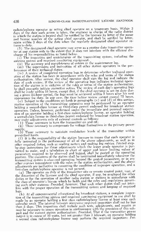
426 SEDOND-CLASS RADIOTELEPHONE LICENSE HANDBOOK
radiotelephone operator as acting chief operator on a temporary basis. Within 3 days of the date such action is taken, the engineer in charge of the radio district in which the station is located shall be notified by the licensee by letter of the name and license number of the acting chief operator, and shall be notified by letter, again within 3 days of the date when the regularly designated chief operator re-turns to duty. ( 5) The designated chief operator may serve as a routine duty transmitter opera-
tor at any station only to the extent that it does not interfere with the efficient dis-charge of his responsibilities as listed below.
(i) The inspection and maintenance of the transmitting system, including the antenna system and required monitoring equipment.
(ii) The accuracy and completeness of entries in the maintenance log. (iii) The supervision and instruction of all other station operators in the per-
formance of their technical duties. ( iv) A review of completed operating logs to determine whether technical oper-
ation of the station has been in accordance with the rules and terms of the station authorization. After review, the chief operator shall sign the log and indicate the date of such review. If the review of the operating logs indicates technical opera-tion of the station is in violation of the rules or terms of the station authorization, he shall promptly initiate corrective action. The review of each day's operating logs shall be made within 24 hours, except that, if the chief operator is not on duty dur-ing a given 24-hour period, the logs must be reviewed within 2 hours after his next appearance for duty. In any case, the time before review cannot exceed 72 hours. ( e) Subject to the conditions set forth in paragraphs (c) and (d) of this section,
routine operation of the transmitting apparatus may be performed by an operator holding a second-class license or third-class permit endorsed for broadcast station operation. Unless, however, performed under the immediate and personal supervi-sion of an operator holding a first-class radiotelephone license, an operator holding a second-class license or third-class permit endorsed for broadcast station operation, may make adjustments only of external controls as follows: ( 1 ) Those necessary to turn the transmitter on and off; (2) Those necessary to compensate for voltage fluctuations in the primary power
supply; (3) Those necessary to maintain modulation levels of the transmitter within
prescribed limits. (f) It is the responsibility of the station licensee to insure that each operator is
fully instructed in the performance of all of the above adjustments, as well as in other required duties, such as reading meters and making log entries. Printed step-by-step instructions for those adjustments which the lesser grade operator is per-mitted to make, and a tabulation or chart of upper and lower limiting values of parameters required to be observed and logged, shall be posted at the operating position. The emissions of the station shall be terminated immediately whenever the transmitting system is observed operating beyond the posted parameters, or in any other manner inconsistent with the rules or the station authorization, and the above adjustments are ineffective in correcting the condition of improper operation, and a first-class radiotelephone operator is not present. ( g) The operator on duty at the transmitter site or remote control point, may, at
the discretion of the licensee and the chief operator, if any, be employed for other duties or for the operation of another radio station or stations in accordance with the class of operator's license which he holds and the rules and regulations govern-ing such other stations: Provided, however, That such other duties shall not inter-fere with the proper operation of the transmitting system and keeping of required logs.
(h) At all noncommercial educational fin broadcast stations, a complete inspec-tion of the transmitting system and required monitoring equipment in use shall be made by an operator holding a first class radiotelephone license at least once each calendar week. The interval between successive required inspection shall not be less than 5 days. This inspection shall include such tests, adjustments, and repairs as may be necessary to insure operation in conformance with the provision of this sub-part and the current station authorization: Provided, That if the transmitter power output is in excess of 10 watts, but not greater than 1 kilowatt, an operator holding a second class radiotelephone license may perform the required inspection: Pro-

BROADCAST RULES AND REGULATIONS 427
vided, further, That if the transmitter power output is 10 watts or less, no such weekly inspection need he made, although this shall in no way relieve such stations from the duty to operate in conformance with the provisions of this subpart and the current station authorization.
DEFINITIONS
SEC. 73.905 Emergency Action Notification System (EANS). The system by which all licensees and regulated services of the Federal Communications Commis-sion, participating non-Government industry entities, and the general public, are notified of the existence of or termination of an Emergency Action Condition result-ing from National, State, or Operational (local) Area situations covering a broad range of emergency contingencies posing a threat to the safety of life or property. The Emergency Action Notification System consists only of the following approved and authorized facilities, systems, and interconnection arrangements: Receipt of the emergency action notification via any one is sufficient to begin emergency actions set forth in Section 73.933.
(a) First Method. Via the internal alerting facilities of the commercial Radio and Television Broadcast-Networks to all affiliates.
(b) Second Method. Via teletype to all standard, fm, and television broadcast and other stations subscribing to the AP and UPI Radio Wire Teletype Networks.
(c) Third Method. Off-the-air monitoring of specified standard, fm, and Me% i-sion broadcast stations by standard, fm, and television broadcast stations and other licensees and regulated services for receipt of the Emergency Action Notification. All broadcast licensees are required to install, maintain and operate radio receiving equipment for receipt of the Emergency Action Notifications and Emergency Action Condition Terminations via this method.
(d) Fourth Method. Off-the-air monitoring of standard, fm, and television broadcast stations by participating non-Government industry entities and the gen-eral public who are listening or viewing or whose radio or television receivers are equipped for actuation by the Attention Signal to receive the Emergency Action Notifications and Emergency Action Condition Terminations.
(e) National-Level Interconnection Arrangements. (1) From the White House to two specified origination points; thence via a dedicated teletype network to specified control points of the commercial Radio and Television Broadcast Networks (ABC, CBS, IMN, MBS, NBC, UPI-Audio, ABC—TV, CBS—TV, NBC—TV) and the American Telephone and Telegraph Co.; thence via the First Method specified in paragraph (a) of this section.
(2) From the White House to two specified origination points; thence via a dedicated teletype network with a dedicated automatic telephone network for backup confirmation and verification purposes; thence via the Second Method spec-ified in paragraph (h) of this section.
(3) Via the Third Method specified in paragraph (c) of this section. (4) Via the Fourth Method specified in paragraph (d) of this section. (f) State-Level Interconnection Arrangements. From State authorities to speci-
fied State Network Primary Control Stations pursuant to the provisions of Section 73.935( a )(I ) via the detailed arrangements specified in the Detailed State EBS Operational Plan; thence via the Third and Fourth Methods set forth in paragraphs (c) and (d), of this section.
(g) Operational (Local) Area-Level Interconnection Arrangements. From Op-erational (Local) Area authorities to specified primary Broadcast Stations for the Operational (Local) Area pursuant to the provisions of Section 73.935( a )( 2 ) via the detailed arrangements specified in the Detailed State EBS Operational Plan; thence via the Third and Fourth Methods set forth in paragraphs (c) and (d) of this section. SEC. 73.906 Attention signal. The signaling arrangement whereby standard.
fm, and television broadcast stations can actuate mute receivers for the receipt of emergency cuing announcements and broadcasts, is as follows:
(a) Cut the transmitter carrier for 5 seconds. (Sound carrier only for tv sta-tions.)
(b) Return carrier to the air for 5 seconds. (c) Cut transmitter carrier for 5 seconds. (Sound carrier only for tv stations.)

428 SEDOND-CLASS RADIOTELEPHONE LICENSE HANDBOOK
( d) Return carrier to the air. ( e ) Broadcast 1,000 hertz steady-state tone for 15 seconds. SEC. 73.907 Emergency Action Notification. The Emergency Action Notifica-
tion is the notice to all licensees and regulated services of the Federal Communica-tions Commission, participating non-Government industry entities, and to the gen-eral public of the existence of an Emergency Action Condition. The Emergency Action Notification is disseminated only via the Emergency Action Notification Sys-tem in accordance with the Detailed non-Government Activation and Termination Procedures and Standing Operating Procedures (SOP's) for the Emergency Broad-cast System which are promulgated and issued only by the Federal Communications Commission to those non-Government entities concerned.
Sec. 73.908 Emergency Action Condition. The Emergency Action Condition is a National, State, or Operational (local) Area emergency situation posing a threat to the safety of life or property covering the period of time between the transmis-sion of an Emergency Action Notification and the transmission of the Emergency Action Condition Termination. SEC. 73.909 Emergency Action Condition Termination. The Emergency Action
Condition Termination is the notice to all licensees and regulated services of the Federal Communications Commission, participating non-Government industry en-tities, and to the general public of the termination of an Emergency Action Condi-tion. The Emergency Action Condition Termination is disseminated only via the Emergency Action Notification System in accordance with the Detailed non-Gov-ernment Activation and Termination Procedures and Standing Operating Proced-ures (SOP's) for the Emergency Broadcast System which are promulgated and is-sued only by the Federal Communications Commission to those non-Government entities concerned. SEC. 73.912. Emergency Broadcast System (EBS ). The Emergency Broadcast
System (EBS) is composed of facilities and personnel of non-Government broad-cast stations and other authorized facilities licensed or regulated by the Federal Communications Commission and participating non-Government industry entities, including approved and authorized integral facilities or systems, arrangements, pro-cedures, and interconnecting facilities, which have been authorized by the Federal Communications Commission to operate on a volutary organized basis during Na-tional, State, or Operational (local) Area situations covering a broad range of emergency contingencies posing a threat to the safety of life or property for the purpose of expeditiously transmitting emergency Presidential Messages, National, State, or Operational (local) Area emergency information, emergency programing, or news to the general public.
Sec. 73.913 Basic Emergency Broadcast System (EBS) Plan. The Basic Emer-gency Broadcast System (EBS) Plan contains, among other things, approved basic concepts and designated systems, arrangements, procedures, and interconnecting facilities to provide the requisite guidance to all non-Government participating ele-ments and industry entities in the detailed development, designation and approval of facilities, mutually compatible operational arrangements, procedures, and inter-connection arrangements for the expeditious dissemination on a voluntary orga-nized basis of emergency information and instructions at the request of National, State, and Operational (local) Area authorities in addition to emergency Presiden-tial Messages, National Programming and News during National, State or Opera-tional (local) Area situations covering a broad range of emergency contingencies posing a threat to the safety of life or property. SEC. 73.914 Emergency Action Checklist for the Emergency Broadcast System
(EBS). The Emergency Action Checklist for the Emergency Broadcast System is a document for posting at all broadcast operating positions of standard, fm, and television broadcast stations, which specifies in summary form, the emergency ac-tions to be taken by the station's operating personnel upon receipt of Emergency Action Notifications, Emergency Action Condition Terminations, and Tests received via the National-Level, State-Level, and Local-Level interconnecting facilities of the Emergency Broadcast System (EBS). SEC. 73.915 NIAC Order. A NIAC Order is a service order previously filed
with the American Telephone and Telegraph Co. providing for approved arrange-ments for program origination reconfiguration of the major commercial Radio and Television (aural) Broadcast Networks (except UPI Audio) voluntarily participat-

BROADCAST RULES AND REGULATIONS 429
ing in the Emergency Broadcast System (EBS). Broadcast networks presently par-ticipating are American Broadcasting Co. (ABC), Columbia Broadcasting System (CBS), Mutual Broadcasting System ( MBS ), National Broadcasting Co. ( NBC), Intermountain Network (IMN), and the United Press International Audio (UPI). Any NIAC Order must meet White House requirements and may be activated only in accordance with the Detailed Activation and Termination Procedures for the Emergency Broadcast System (EBS), and Standing Operating Procedures ( SOP's). SEC. 73.916 Emergency Broadcast System (EBS) Authorization. (a) An
Emergency Broadcast System (EBS) Authorization is an authorization issued by the Federal Communications Commission only to the licensees of Broadcast sta-tions subject to the provis:ons of this part to permit operation of such stations, as well as associated auxiliary broadcast stations subject to Part 74 of this chapter on a voluntary organized basis during a National-level Emergency Action Condition, consistent with the provisions of this subpart and the Basic Emergency Broadcast System (EBS) Plan, including the annexes and supplements to that plan. A broad-cast station licensee will be issued an Emergency Broadcast System Authorization only in accordance with the Criteria for Eligibility set forth in the Basic Emergency Broadcast System (EBS) Plan, which will remain valid concurrently with the term of the broadcast station license, so long as the station licensee continues to comply with the Criteria for Eligibility.
(b) An Emergency Broadcast System (EBS) Authorization is not required in order to participate on a voluntary organized basis in State and Operational (local) Area Emergency Broadcast System operations as set forth in Section 73.935. SEC. 73.917 Primary Station Emergency Broadcast System (EBS) Authoriza-
tion. A Primary Station Emergency Broadcast System (EBS) Authorization is the authorization issued to one or more broadcast station licensees in an Operational (local) Area assigning such licensees the responsibility for broadcasting a common emergency program for the initial period of, or for the duration of a National-level Emergency Action Condition. Broadcasts by such stations are intended for direct public reception in an Operational (local) Area, as specified in an approved De-tailed State Emergency Broadcast System (EBS) Operatfonal Plan. SEC. 73.918 Alternate Station Emergency Broadcast System (EBS) Authoriza-
tion. An Alternate Station Emergency Broadcast System (EBS) Authorization is the authorization issued to one or more broadcast licensees in an Operational (local) Area a signing such licensees as specified alternates. An Alternate Station will as-sume broadcasting responsibility in accordance with the provisions of the Detailed State Emergency Broadcast System (EBS) Operational Plan during a National-level Emergency Action Condition. SEC. 73.919 Primary Relay Station Emergency Broadcast System (EBS) Au-
thorization. A Primary Relay Station Emergency Broadcast System (EBS) Authori-zation is the authorization issued to one or more broadcast licensees in an Opera-tional (local) Area assigning such licensees the function of emergency program dis-tribution or relay service of emergency programming during a National-level Emer-gency Action Condition to stations holding Primary or Alternate Station Emergency Broadca• t System (EBS) Authorizations, in accordance with an approved Detailed State Emergency Broadcast System (EBS) Operational Plan. SEC. 73.920 Alternate Relay Station Emergency Broadcast System (EBS) Au-
thorization. An Alternate Relay Station Emergency Broadcast System (EBS) Au-thorization is issued the authorization issued to one or more broadcast licensees in an Operational (local) Area assigning such licensees as specified alternates to sta-ffons holding Primary Relay Emergency Broadcast System (EBS) Authorizations. In the event a Primary Relay Station is unable to assume its initial operational func-tions, or discontinues such operation for any reason, an Alternate Relay Station will assume those operational functions during a National-level Emergency Action Con-dition, in accordance with the "alternate" designations ( 1st, 2d, 3d, 4th, etc.) con-tained in the approved Detailed State Emergency Broadcast System (EBS) Opera-tional Plan. SEC. 73.921 Non-Participating Station. A Non-Participating Station is a broad-
cast station which is not voluntarily participating in the Emergency Broadcast Sys-tem (EBS) and does not hold an Emergency Broadcast System (EBS) Authoriza-tion. Such stations are required to discontinue operations for the duration of a National-Level Emergency Action Condition.

430 SEDOND-CLASS RADIOTELEPHONE LICENSE HANDBOOK
Sec. 73.924 Common Program Control Broadcast Station. A Common Program Control Broadcast Station is a Primary Broadcast Station in each Operational (local) Area assigned the responsibility for coordinating the operations for the broadcasting of the common program for the Operational (local) Area. In the event a Common Program Control Broadcast Station is unable for any reason to carry out this responsibility, other Primary and Alternate Broadcast Stations in the Opera-tional ( local) Area will be assigned as the Common Program Control Broadcast Sta-tion in progressive order, as set forth in the approved Detailed State Emergency Broadcast System (EBS) Operational Plan. SEC. 73.925 Emergency Broadcast System (EBS) Programming Priorities. (a)
Program priorities for the Emergency Broadcast System (EBS) are as follows: Priority One—Presidential Messages. Priority Two—State Programing. Priority Three—Operational Area ( Local ) Programing. Priority Four—National Programing and News.
(b) The Common Program Control Broadcast Station is responsible for coordi-nating the operations of the participating stations in the Operational ( Local) Area in the broadcast of a common program for the Operational ( Local) Area in accord-ance with the program priorities set forth in paragraph (a) of this section.
(c) All authorized participating stations that remain on the air in accordance with the Basic Emergency Broadcast System (EBS) Plan and the Detailed State Emergency Broadcast System (EBS) Operational Plan must carry Presidential Mes-sages "live" at time of transmission.
(d) The nationwide commercial Radio and Television (aural) Broadcast Net-work program distribution facilities shall be reserved exclusively for the distribution of Presidential Messages (Priority One) and National Programing and News (Pri-ority Four), National Programing and News which is not broadcast at the time of original transmission shall be recorded locally by the Common Program Control Broadcast Station for broadcast at the earliest opportunity consistent with Opera-tional ( Local) Area requirements. SEC. 73.1201 Station identification. (a) When regularly required. Broadcast
station identification announcements shall be made: (1) At the beginning and end-ing of each time of operation, and (2) hourly, as close to the hours as feasible, at a natural break in program offerings. Television broadcast stations may make these an nouncements visually or aurally.
(b) Content. (1) Official station identification shall consist of the station's call letters immediately followed by the name of the community or communities speci-fied in its license as the station s location.
(2) When given specific written authorization to do so, a station may include in its official station identification the name of an additional community or communi-ties, but the community to which the station is licensed must be named first.
(3) A licensee shall not in any identification announcements, promotional an-nouncements or any other broadcast matter either lead or attempt to lead the sta-tion's audience to believe that the station has been authorized to identify officially with cities other than those permitted to be included in official station identifica-tions under subparagraphs ( 1) and (2) of this paragraph. ( c) Channel—(1) General. Except as provided in subparagraph ( 2 ) of this par-
agraph, in making the identification announcement the call letters shall be given only on the channel of the station identified thereby.
(2) Simultaneous a-m—fm broadcasts. If the same licensee operates an fm broadcast station and a standard broadcast station and simultaneously broadcasts the same programs over the facilities of both such stations, station identification an-nouncements may be made jointly for both stations for periods of such simultaneous operation. If the call letters of the fm station do not clearly reveal that it is an fm station, the joint announcement shall so identify it. SEC. 73.1205 Fraudulent billing practices. No licensee of a standard, fm, or
television broadcast station shall knowingly issue to any local, regional or national advertiser, advertising agency, station representative, manufacturer, distributor, job-ber, or any other party, any bill, invoice, affidavit or other document which con-tains false information concerning the amount actually charged by the licensee for the broadcast advertising for which such bill, invoice, affidavit or other document is issued, or which misrepresents the nature or content of such advertising, or which

BROADCAST RULES AND REGULATIONS 431
misrepresents the quality of advertising actually broadcast (number or length of advertising messages) or the time of day or date at which it was broadcast. Li-censees shall exercise reasonable diligence to see that their agents and employees do not issue any documents which would violate this section if issued by the licensee. SEC. 73.1206 Broadcast of telephone conversations. Before recording a tele-
phone conversation for broadcast, or broadcasting such a conversation simultane-ously with its occurrence, a licensee shall inform any party to the call of the licens-ee's intention to broadcast the conversation, except where such party is aware, or may be presumed to be aware from the circumstances of the conversation, that it is being or likely will be broadcast. Such awareness is presumed to exist only when the other party to the call is associated with the station (such as an employee or part-time reporter), or where the other party originates the call and it is obvious that it is in connection with a program in which the station customarily broadcasts telephone conversations. SEC. 73.1207 Rebroadcast. (a) The term "rebroadcast" means reception by
radio of the programs of a radio station, and the simultaneous or subsequent re-transmission of such programs by a broadcast station. NcrrE 1: As used in Section 73.1207 "program" includes any complete program
or part thereof. NOTE 2: The transmission of a program from its point of origin to a broadcast
station entirely by common carrier facilities, whether by wire line or radio, is not considered a rebroadcast.
(b) No broadcasting station shall rebroadcast the program, or any part thereof of another U.S. broadcasting station without the express authority of the originat-ing station. A copy of the written consent of the licensee originating the program shall be kept by the licensee of the station rebroadcasting such program and shall be made available to the Commission upon request. Stations originating emergency communications under a Detailed State EBS Operational Plan shall be deemed to have conferred rebroadcast authority on other participating stations. The broadcast-ing of a program relayed by a remote pickup broadcast station (Section 74.401 of this chapter) is not considered a rebroadcast. SEC. 73.1208 Broadcast of taped, filmed, or recorded material. (a) Any taped,
filmed or recorded program material in which time is of special significance, or by which an affirmative attempt is made to create the impression that it is occurring simultaneously with the broadcast, shall be announced at the beginning as taped, filmed or recorded. The language of the announcement shall be clear and in terms commonly understood by the public. For television stations, the announcement may be made visually or aurally.
(b) Taped, filmed, or recorded announcements which are of a commercial, pro-motional or public service nature need not be identified as taped, filmed or recorded.

Answers to Tests
Chapter 6
1. A. 2. B. If the original is found mean-
while it is necessary that you return either one, original or duplicate, to the FCC.
3. B. 4. D. Station logs must be signed
when the operator goes on and off duty. Likewise log records must be signed by the licensed maintenance technician and must also include data on the nature of the trans-mitter repairs.
5. D. 6. B. 7. B. 8. A. 9. B.
10. D. 11. D.
Self-Test
12. A. 13. C. 14. A. 15. C. 16. B. 17. A. The operator must learn to be
patient under adverse propagation conditions. Repeated calls should be only made if one is certain the transmissions cause no interference or hamper other communications that share the same frequency.
18. D. 19. C. 20. C. 21. A. 22. B. 23. C. 24. D. 25. B.
Chapter 7
1. A. 2. A. 3. B. The kilowatt-hour kWh is the
unit measured by your electrical meter. It measures the quantity of electrical energy you have con-sumed over a period of time.
4. D. 5. B. 6. A. 7. C. 8. D. When the length is doubled the
resistance increases a like amount. Likewise a reduction in the cir-cular area produces a correspond-ing increase in resistance. This means that the resistance has been increased by a factor of 8 (2 x 4). The answer is 8 ohms.
9. C. A step-up turns ratio primary-to-secondary steps up the voltage and steps down the current from 10 volts to 60 volts and from 1.8 ampere to 0.3 ampere.
10. C.
Self-Test
11 D. One might jump to the conclu-sion that A was the correct answer. However the color code for one is brown and not black.
12. C. 13. C. Maximum power is transferred
when the ohmic value of the load matches the ohmic value of the source.
14. C. A No. 8 is a thicker gauge wire than a No. 16.
15. D. 16. A. 17. B. 18. B. 19. D. 20. C. Note that the second harmonic
power is 1/100 of the fundamental output. That is to say that it is 20 dB less than the fundamental out-put.
300 300 21. B. X = - = one-half meter.
full. - 600
22. D. Keep in mind that for ac power
432

ANSWERS TO TESTS
measurements that the product of a voltmeter and current-meter read-ings is only the apparent power. Whenever the power factor is sig-nificantly lower than unity, the true power is considerably lower.
23. 24.
25.
433
B. B. When resistance and reactance are equal, whether they be con-nected in series or parallel, the phase angle is 450. A.
Chapter 8 Self-Test
1. B. This high input capacity is largely the result of the higher grid-to-plate interelectrode capacity 17. of the triode.
2. C. 3. C. 4. A. Such a short reduces the grid
bias to 0 and a high plate current results.
5. B. The suppressor grid blocks the 18. transfer of secondary electrons from plate to screen grid.
6. D. 7. C. 8. D. The gain of an amplifier is al- 19.
ways less than its amplification 20. factor j.t. More information is neces-sary to obtain an answer.
9. D. 10. A. 11. B.
Cain = iati. 30 x 20K RL «- 50K + 20K 85
12. D. 13. A. 14. A. 15. B.
1000 Xc = - = 200
5
1 C = = 8 ILF
6.28 x 100 x 200
The rule-of-thumb employed is that the reactance of the capacitor should be one-fifth of the ohmic value of the cathode resistor at the lowest audio frequency.
16. D. A positive signal on the base de-creases the forward biasing of the
21. 22.
23. 24.
25.
emitter junction and the base, col-lector and emitter currents fall. D. The answer is the same as Num-ber 16. It does not depend on the type of circuit configuration but whether or not the transistor is a pnp or npn type. Again the for-ward biasing is decreased and there is a drop in the base current. A. If one employs an npn transistor in the same circuit, a positive sig-nal will contribute additional for-ward biasing and, therefore, there is an increase in the base current. B. B. It is the plate current in the cathode resistor that develops the bias or:
EK 2 RK = - 500 ohms
0.004
D. A. Matching impedance transfers the maximum power to the load. However, this can be a distorted output and in a practical situation where one wishes to obtain maxi-mum undistorted power output from a triode it is customary to use a load resistance that is two or more times higher than the plate resist-ance of the triode. B. B. It is the plate current that is present in the plate load resistor. Therefore, the dc drop across the plate resistor is 162 volts (27,000 x 0.006). The operating dc plate voltage is the difference between this value and the supply voltage or 138 volts ( 300 - 162). A.
Chapter 9 Self-Test
1. C. When the hydrometer indicates 4. B. The power law solves the ques-a low specific gravity it means that lion: the acid content is insufficient.
P = EI = 650 x 0.05 = 32.5 watts. 2. D. 3. C. 5. D.

434 SECOND-CLASS RADIOTELEPHONE LICENSE HANDBOOK
6. C. One-half of the full secondary 11. voltage appears between the center tap of the secondary and either end. 12. The input capacitor under a no- 13. load condition charges to the peak 14. value or 352 volts (250 X 1.414 ). 15.
7. A. The equation is: 16. % Regulation =
No-load Voltage - Full-load Voltage Full-load Voltage 320 - 280 17.
280 14.2% 18. 19.
8. C. With 10% voltage regulation it 20. means that the full-load voltage 21. •drops to 10% of the no-load value 22. or 540 volts ( 600 - 0.1 X 600). 23.
9. C. 24. 10. B. 25.
B. The dynamotor converts a low dc voltage to a high dc voltage. D. C. D. A. B. In the case of the dc motor the brushes and commutator switch over the current direction and cause the changing magnetic field neces-sary for motor action. D. C. D. A. D. C. B. D. B.
Chapter 10 Self-Test
1. D. 2. A. 3. D. 4. C. The reactance of the capacitor
decreases with frequency. Conse-quently more signal is transferred at a high frequency than at a lower one.
5. D. 6. B. Turns ratio equals the square
root of the impedance ratio or:
Turns Ratio = 71; = =
/ 3-6r = 21-to-1.
7. D.
Chapter 11
1. C. In an a-m system the emission bandwidth is twice the highest audio frequency. In the case of a 3000-Hz tone the emission band-width would be 6000 Hz.
2. D. 2.5 kHz. Only one sideband is transmitted. Therefore the band-width is determined by and is equal to the highest audio frequency.
3. D. 4. A. 5. D. 6. D.
8. D. 9. B.
10. A. 11. C. 12. D. 13. A. 14. C. 15. D. 16. C. 17. B. 18. D. 19. D. 20. D. 21. B. 22. B. 23. A. 24. D. 25. A.
Self-Test
7. D. With oscillator tuned to the low side of the signal frequency, the oscillator must be set on 99.3 MHz (110-10.7). The image frequency is on the low side of this value by an amount equal to the i-f fre-quency or 88.6 MHz (99.3-10.7).
8. D. 9. D.
10. D. 11. B. If the rf excitation is inadequate
the modulated amplifier cannot fol-low the modulation crest and there

ANSWEI1S TO TESTS
is a downward kick in the antenna-current meter reading.
12. C. This is an example of the oscil-lator being set on the high-fre- 18. quency side of signal frequency (this is the converse of the situa-tion in question 7). The oscillator frequency is 1065 kHz (610 19. 455). The image frequency is an additional 455 kHz higher or 1520 (1065 455). If a 1520-kHz com-ponent were tc reach the mixer, it 20. would result a 455-kHz corn- 21. ponent that could interfere with the reception of the 610-kHz desired signal.
13. C. Alignment starts at the detector transformer and proceeds back in a series of steps to the antenna in-put system.
14. D. 15. D. 16. B. The equation is:
% of Modulation =
E. - EMI'S 4.5 - 1.5 2E0 2 x 3 - 50%
17. D. When there is 50% modulation the sideband amplitude is only one-quarter the amplitude of the carrier. Therefore the power in each side-band is only 1/16 of the power in the carrier. Since there are two sidebands, one on each side of the
1. B.
Modulation Index = Deviation
Modulating Frequency 15,000
= 3 5000
2. B. 3. D. 4. D. 5. A. 6. B. 7. D. 8. D. 9. A.
10. C. 11. D. 12. A. 13. D. 14. D. 15. C. 16. C.
435
carrier frequency, the total side-band power is 1/8 of the carrier power. B. It is this nonlinear activity that produces the sidebands. In this case distortion is being used to advan-tage. C. The modulator power output for 100% plate modulation must equal one-half of the de input power to the modulated amplifier. D. B. The equation is:
% Efficiency =
Rf Power Output 450 - - 90% De Power Input 500
22. C. 23. B. 24. A. 25. B. Keep the terms frequency shift
or dynamic instability and nega-tive carrier shift in mind. Fre-quency shift or dynamic instability refers to an actual shift in the car-rier frequency with modulation. However, the term negative carrier shift refers to a shift in the dc plate-current meter reading of the modu-lated amplifier with modulation. The latter has nothing to do what-soever with the frequency of the carrier.
Chapter 12 Self-Test
17. C. There are four significant side-band pairs on each side of the cen-ter frequency (carrier frequency). Therefore, the total emission band is 8 X 500 = 4000 Hz.
18. D. 19. A. The frequency difference is
12,606,000 - 12,600,000 = 6000 Hz. The decimal relationship be-comes:
Decimal Ratio
6,000 = 0.000476
12,600,000
In percentage this is 0.0476%. 20. D. 21. B. 22. C. 23. D. 24. C. 25. D.
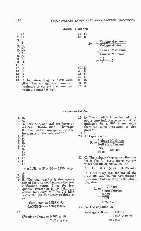
436 SECOND-CLASS RADIOTELEPHONE LICENSE HANDBOOK
Chapter 13 Self-Test
I. C. 2. C. 3. B. 4. A. 5. D. 6. D. 7. B. 8. A. 9. B.
10. D. 11. A. 12. D. 13. D. 14. B. 15. D. 16. D. In determining the SWR ratio
either the voltage maximum and minimum or current maximum and minimum must be used.
17. C. 18. B.
19. D. 20. D. 21. D. 22. D. 23. B. 24. B. 25. A.
Chapter 14 Self-Test
1. B. 2. A. 3. A. Both A3A and A3J are forms of
sideband transmission. Therefore the bandwidth corresponds to the frequency of the modulation.
4. D. 5. D. 6. B. 7. C. 8. A. 9. C.
10. D. 11. D. 12. C. 13. C.
P =h2RA= 5' X 50 = 1250 watts
14. A. 15. B. 16. B. The dial reading is three-quar-
ters of the distance between the two calibration points. Since the fre-quency separation is 10 kHz, the actual frequency will be 7.5 kHz above the low-frequency calibration or:
Frequency = 6.588MHz 0.0075MHz = 6.5955MHz.
17. B.
Effective voltage = 0.707 x 10 = 7.07 amperes.
Swr Voltage Maximum
= Voltage Minimum
Current Maximum = Current Minimum
1.5 , = - 1 .a
1
18. D. The circuit is inductive but it is not a pure inductance as would be indicated by a 90° phase angle therefore some resistance is also present.
19. B. 20. A. Equation is:
Voltage Maximum -
Full Scale Current 500
= ITC01 = 500'M
21. C. The voltage drop across the me-ter is the full scale meter current times the meter resistance or:
V = IR = 0.001 x 25 = 0.025 volt.
It is necessary that 99 mA of the total 100 mA current pass through the shunt. Voltage drop is the same. Equation:
112 Voltage Shunt Current 0.025 .099
= 0.2525 ohm.
22. A. The equation is:
Average Voltage = 0.636E1. = 0.636 x 24/2 = 7.632

ANSWERS TO TESTS
23. D. 24. B. 25. D. 60 dB drop corresponds to
1/1000 of initial voltage or:
1 Harmonic Voltage = oo x 10
= 0.01 volt.
Experience Test
1. A. 2. D. 3. D. 4. B. 5. D. 6. B. 7. C. 8. C. 9. D.
10. B. II. A. Type approved equipment has
been checked out by the Federal Communications Commission. De-sign cannot be changed without FCC approval. Type accepted equipment is manufactured units that the manufacturer guarantees to perform within the specifica-tions submitted to the FCC.
12. B. A new style antenna because of characteristics that may differ from the previous antenna can have an influence on the operation of the transmitter. In a similar manner, just changing a radio-frequency tube or transistor or other device may affect power output and mod-ulation percentage.
13. A. 14. B. 15. D. 16. C. When the dc input power is
less than 3 watts there is some re-laxation in certain frequency tol-erances.
17. C. 18. A. 19. D. 20. B. 21. C. 22. C. 23. A. 24. C. 25. C. If the transmitter is crystal con-
trolled recall that performance measurements must be made yearly by a licensed first- or sec-ond-class radiotelephone techni-cian.
26. B. 27. D. 28. A. WWV is the reference fre-
quency. Approved frequency me-ters can be used for checking
437
transmitter frequencies. However, these approved meters are cali-brated by, or must be periodically checked against, the WWV trans-missions. Frequency accuracy must be of a tolerance that is one-half or better than the FCC tolerance for the transmitter under test. For example, if the FCC tolerance for the transmitter is 0.0005%, the tolerance for the frequency meter must be 0.00025%. One must lean on the WWV transmissions if this instrument tolerance is to be main-tained.
29. B. 30. D. 31. B. 32. D. 33. C. 34. A. 35. B. 36. D. 37. D. 38. D. When capacitors are charged
and the source of power is re-moved there are only so many coulombs of energy (CE) stored in the electrostatic fields. When other capacitors are added to the combination the energy is redis-tributed and the net charge volt-age declines. In the example ca-pacitance increased from 0.005 ¿IF to 0.015 le with the addition of the third capacitor. Therefore the net voltage across the combination and across this individual capacitor must drop from 100 volts to 33% volts.
C,E, = C2E2 C, E2 = E,
0.005 E2 0.015 = 100 E2 = 33% volts
39. B. 40. A. Again maximum power trans-
fer is made by matching the equiv-alent series resistance of the gen-erator.
41. C.

438 SECOND-CLASS RADIOTELEPHONE LICENSE HANDBOOK
42. D. One must be careful about the Q of the parallel resonant circuit depending upon whether the resis-tance is in series or parallel. In the ease of the resistance that is in series with or is reflected in series by a load, the Q declines with the ohmic value of this resistance ac-cording to:
X Q
(This is the same as series reso-nant case.) If we are considering any resis-tance that is shunted across or in parallel with the parallel resonant circuit, the Q equation must be flipped over to:
Q
This is logical when we consider the presence of the resistance across the parallel impedance of the inductor and capacitor. Cer-tainly the lower this resistance is made, the lower becomes the im-pedance and Q of the combina-tion.
43. B. The power removed is a func-tion of the total resistance and the applied voltage or:
E2 200' P = = 131‘4 = watt R 1200 -I- 1800 "
44. D. 45. B. Power = 385 X 120 = 46.2 kWh 46. B. Peak voltage equals V-2- x Ei.
=1.414 x 10 = 14.14 volts. 47. D. The standard impedance equ-
ation is used:
Z VR2 -I- X' The Xi. depends upon frequency or:
X = 2 7T fL = 6.28 x 1000 x 1 = 6280 ohms
Z = V 50002 62802 =-• 8027 ohms
48. B. A 20 dB gain corresponds to a tenfold increase in voltage.
49. A. The loss of 20 dB corresponds to a 1/100 decline in power. This is written as 10 -2 x watts.
50. D. 51. C. In an ac circuit the power con-
sumed is a function of the power factor. The true power becomes:
P = EI x Power Factor = 110 x 7 X 0.35 = 269.5 watts
52. B. The period of the wave is 0.2 seconds ( 2/10 ). Frequency is
1 Period
or:
F = -1 = 0.2 = five hertz T
53. A. Wavelength is the quotient of the velocity over frequency or:
300 x 10" à =.: 5 = 60 x 10" meters
54. A. In a series circuit it is the higher reactance that limits charge motion (current). In the example, it is the capacitive reactance that is greater than the inductive re-actance. Therefore the series cir-cuit is capacitive and the source current leads the source voltage.
55. B. In a parallel circuit it is the lower reactance that determines the charge motion (current). It is the inductive reactance that is lower than the capacitive reac-tance. Therefore the circuit be-comes inductive and the source voltage leads the source curent.
56. D. The true power as read by the wattmeter is 400 watts. However, the product of the voltage and current is 480 watts. This is the apparent power. The power fac-tor is their quotient.
True Power Power Factor = Apparent Power
400 = 4 x 120 = 0.83
57. A. A common-base amplifier does have voltage gain. However, it has a very low input resistance. In operation, it is similar to a vacuum-tube grounded-grid circuit.
58. B. 59. D. 60. C. 61. A. For an npn transistor the col-
lector junction is reverse biased by applying a positive voltage to the collector and a negative volt-age to the base.
62. C. Practical gain of a vacuum tube stage is less than the amplification factor (s).
63. A. 64. D. Like a single-tube vacuum-
tube phase inverter which has out-puts removed from plate and cath-

ANSWERS TO TESTS
ode, a transistor version would have its outputs taken from the collector and emitter.
65. D. Since the operating range ex-tends between -1 and -5 volts it will accommodate a 4-volt (5-1) peak-to-peak signal. This corre-sponds to a 2-volt peak signal. Rms value is 1.414 volts (0.707 X 2 ).
66. D. Both the plate and screen grid currents are present in the cathode resistor. This amounts to 12 inA (10 -I- 2). The required value of the cathode resistor is 833 ohms (10/0.012).
67. D. 68. C. 69. A. 70. C. 71. D. 72. A. This value is twice the ac
power frequency. 73. C. 74. B. 75. B. A 60 ampere-hour lead-acid
storage battery delivers 7.5 am-peres for eight hours (60/8).
76. D. The power law solves the prob-lem:
P 18 I = - = = 1.5 ampere
E 12
77. A. 78. D. The full secondary voltage is
990 volts ( 11C x 9). The voltage across one-half of the secondary is one-half of this value or 495 volts mis. The input capacitor under a no-load condition charges to the peak value of this voltage or 690 volts ( 495 X 1.414 ).
79. D. The full wave and bridge rec-tifier pulsations occur with twice
439
the power-line frequency. The ripple-frequency rate for half-wave rectifier is the same as the line frequency.
80. B. The semiconductor diodes have a lower peak inverse voltage but they can be readily connected in series groups if a higher PIV is desired.
81. D. 89. D. Keep in mind that the turns
ratio equals the square root of the impedance ratio. Conversely, the impedance ratio equals the square of the turns ratio as shown:
Turns Ratio = Nr/Ns =
Turns Ratio = = 3.16 /2 00 000 2
Impedance Ratio .= Zr/Zs =
83. C. 84. C. A 20 dB rise means a 100-fold
increase while a 20 dB decline represents a drop to 1/100 of the initial power.
85. B. 86. B. 87. D. 88. A. 89. D. 90. C. 6.6 MHz is an odd-order har-
monic ( 3rd ). D. D. A.
91. 92. 93. 94. C. 95. B. 96. D. 97. 1) 98. 13 99. B
100. 13.
Experience Test II
1. 1). 2. D. The first two questions show a
method of questioning that is of-ten used in FCC examinations. You are to select the most com-plete answer. In example 2, both A and B are correct hut the proper answer is D in terms of multiple-choice evaluation.
3. C. 4. D. Overmodulation is to be
avoided because it limits the ef-fective transmission range of the station because of speech distor-tion. However, it is not direct grounds for license suspension.
5. C. 6. B. 7. B. 8. B. This is a problem when one
must transmit from a location near operating machinery or in traffic.

B.
440 SECOND-CLASS RADIOTELEPHONE LICENSE HANDBOOK
The development of noise-cancel-ling microphones has aided this problem. They must be close-talked to be really useful. Close-talk but do not shout.
9. A. 10. A. 11. C. The lower the wire gauge num-
ber, the greater is the diameter of the wire.
12. C. 1:3. D. 14. 15. I). 16. A. 17. B. The equation is:
Rf Power Output Dc Input Power
Efficiency
1000 0.85-
= 1176 watts
18. C. 100% modulation requires that the audio power be one-half of the de power input or 588 watts (1176/2).
19. B. 20. A. In the case of 100% modula-
tion each sideband has a magni-tude of one-half of the carrier am-plitude or one-fourth the carrier power. Since there are two side-bands, the total sideband power is one-half of the carrier power. Side-band power is also one-third of to-tal radiated power ( carrier -I- side-bands ).
91. D. If the carrier power output of a transmitter is 100 watts, side-band power is 50 watts for 100% modulation. Therefore, the total power output is 150 watts ( 100 -1-50). Sideband power by itself is only 50 watts. Therefore the total power is three tirnes greater than the sideband power ( 150/50) while carrier power is twice the sideband power ( 100/50 ).
CO. B. 23. D. 24. C. The power output of the trans-
mitter is determined with the power law:
Rf Power Output = PR = 3' x 50 = 450 watts.
Inasmuch as the efficiency is 90%, the de input power is:
De Rf Power Output Input Power =
Efficiency 450
=7 0.9 = 500 watts
25. 26. A. The deviation ratio is deter-
mined by the maximum permissi-ble deviation and the highest mod-ulating frequency or:
Deviation Ratio Permissible Deviation
Highest Audio Frequency 5000
= :3000 = 1.66
B.
"r7. B. 28. C. '"9. C. The frequency tolerance of the
measuring instrument must be twice as good as the FCC fre-quency tolerance for the specific radio service. Therefore, the tol-erance of the frequency meter must be 0.00025% (0.0005/2).
30. D. 31. D. If the frequency tolerance is
0.001% then the maximum fre-quency drift is:
Permissible Frequency Shift = 0.00001 x 25,000,000 = -±-250 Hz
32. B. The crystal oscillator operates on a frequency that is one-quarter of the transmit frequency (25/ 6.25). Therefore, the maximum drift of the crystal oscillator may only be one-quarter of the previ-ous computation for the carrier frequency or 62.5 Hz (250/4).
:33. C. 34. D. 35. B. 36. D. 37. A. 38. D. 39. C. 40. A. 41. D. 42. A. 43. D. 44. C. 45. A. 46. A. 47. B. 48. D. 49. D. 50. D.

ANSWERS TO TESTS
51. D. Since the temperature advance is 25°, there will be a 125-Hz in-crease per megahertz ( 5 X 25). The frequency of the crystal is 6 Nfllz instead of 1 MHz. Therefore, there is a total rise of 750 Hz (125 x 6).
52. C. It is the impedance that de-termines the current level. There-fore:
E 120 L = ,375- = 240 ohms.
53. Fig. 9-3. 54. Figs. 9-5 and 9-6. 55. Fig. 9-4. 56. Figs. 9-5 and 9-8. 57. Figs 8-10, 8-12 and 8-13. 58. Figs. 8-21, 14-20, 14-21. 59. Fig. 10-4A. 60. Figs. 8-24 and 10-3A. 61. Fig. 14-19. 62. Fig. 10-48. 63. Figs. 10-7 and 10-8. 64. Figs. 12-10 and 12-1. 65. Fig. 11-11A. 66. Fig. 10-24. 67. Fig. 10-28. 68. Figs. 10-15 and 10-12. 69. Figs. 10-16 and 10-17. 70. Figs. 10-13 and 8-12. 71. Figs. 11-4, 11-5 and 14-19. 72. Fig. 8-27. 73. Fig. 8-11. 74. Fig. 10-3C. 75. B. The total multiplication is 2 x
2 x 3 = 12. Output frequency is 180 MHz (12 x 15).
76. A. 77 78. B. 79. B. 80. C. 81. B. Bias calculation is:
Voltage = 0.0003 x 47000 = 14.1 volts
82. A. The equation is:
De Power Input = 0.01 x 275 = 2.75 watts.
83. C. Wattage that is required is one-half the de power input or 1.38 watts ( 2.75/2
84. D. 85 86 87. D. 88. A. The plate current dip occurs at
resonance. Current rises when de-tuned on either side of signal fre-quency.
. B.
. A.
. C.
441
89. D. 90. D. 91. B. The resonance equation is:
1
27r V LC
1
- 6.28 V 10 x 10-" x 200 x 10'
= 3.56 MHz
92. D. A series resonant circuit has minimum impedance at resonance and draws maximum current from the source. The Q is the ratio of reactance to the equivalent series resistance.
93. D. The reactive components cancel and the only impedance is that contributed by the resistance it-self. Therefore the series resonant circuit itself is resistive.
94. D. On the high-frequency side of resonance the inductive reactance is greater than the capacitive re-actance and, therefore, it has a limiting influence on the current. The circuit is said to be inductive on the high frequency side of reso-nance.
95. B. The saine equation is used to calculate resonance for both series and parallel resonant circuits.
96. D. Impedance of a parallel reso-nant circuit is maximum at the resonant frequency. Therefore cur-rent demand is minimum but the voltage drop across the resonant circuit is maximum.
97. B. The impedance is resistive and the actual impedance is equal to the effective parallel resistance. The Q of a parallel resonant cir-cuit in ternis of the effective par-
Resistance . allel resistance is ( just
Reactance the opposite of the series resonant case).
98. D. On the high-frequency side of resonance the capacitive reactance is lower than the inductive reac-tance and a higher current results because of the drop in impedance. A parallel resonant circuit on the high-frequency side of resonance is capacitive. Remember that the impedance of a series resonant cir-cuit off resonance increases, while the impedance of a parallel reso-nant circuit off resonance de-creases.

442 SECOND-CLASS RADIOTELEPHONE LICENSE HANDBOOK
99. C. This is a method of blocking in-terfering signals from the input of a communications receiver.
100. D. The parallel combination of Li-Cl has a high impedance at the resonant frequency. If it is tuned to the interfering frequency signal it will block the transfer of that signal to the receiver input.
The impedance of a series resonant circuit is minimum at resonance. Therefore if L2-C2 is tuned to the interfering signal frequency there is additional rejection of the un-desired signal because L2-C2 places a low impedance shunt across the receiver input at the undesired frequency.

Index
A
Absorption wavemeter, 58-60 using the wavemeter, 59-60 wavemeter as an rf indicator, 60
Acorn tube, 231 Adjustment, transmitter tuning and, 86-
126 circuit description, 89-93 general considerations, 86-89
Alternating and direct current, 165-177 calculations, 172-175 circuits, 170-172 definitions and units, 165 electronic components, 166-170
Amplifiers and oscillators, 215-240 audio, 215-223 high-powered rf, 110-114 power, 219 push-pull, 219-220 radio-frequency. 223-232
Amplitude modulation, 46-47 double-sideband, 47
Amplitude-modulation systems, 243-259 receivers, 254-259 single sideband, 252-254 transmitters, 243-245
Antenna( s), 288-295 and lines, 283-296 corona discharge, 291 diversity reception, 291 field strength, 290 polarization, 29_ power gain, 290-291 systems, major units of, 150-154
Assignments, definitions of station, 17 Audio amplifiers, 215-223 Authority, operating, 11-13
radiotelephone second-class operator license, 11 third-class operator permit, 12
restricted radiotelephone operator permit, 12-13
Aurora borealis, 41 Aviation services, 18 Average current, 300
Bandpass filter, 171 Band-stop filter, 171 Base station, 15 Basic
law, 156-157 and operating practices, 155-164
operating practice, 157-162 Batteries, 209-210 Beam-power tube, 180 Bending, tropospheric, 44-45 Beat-frequency oscillator, 256-257 Bias
cathode, 215-216 grid-leak, 216
Bleeder resistor, 208 Broadcast transmitters, 136-149 Bridge rectifier, 206 Business Radio Service, 19-24
technical standards, 21-23 frequency, 21 modulation, 22 other factors, 22 power, 21 transmitter measurements, 22-24
Card, verification, 14 Cathode
bias, 215-216 follower, 184-185, 217 -ray oscilloscope, 301-302
Cavity resonator, 287 Carbon microphone, 223 Carrier frequency, 250 Characteristics, transmission, 41-55 Checks
modulation, 124-125 troubleshooting quick, 109
Choke radio-frequency, 225 swinging, 208
Circuit(s) s ) discriminator, 274 representative, 117-121
443

444 SECOND-CLASS RADIOTELEPHONE LICENSE HANDBOOK
Circuit( s )—cont squelch, 275-276 speech-clipping, 80
Citizens radio service, 18, 25-32 Class-A station, 25 Class-C station, 28 Class-D station, 28 duration of transmissions, 30 operator license requirements, 31-32 prohibited uses, 28-30 technical requirements, 32-34
emission limitations, 33 frequency tolerance, 33 modulation requirements, 33-34 transmitter power, 32
Coil, loading, 292 Collector-base junction, 192 Commercial
frequency meter, 68-71 rf power meters, 66-68
Common-emitter circuit, 195 Communications monitor, 85 Commutator, 210 Components, electronic, 166-170 Considerations, technical, 128 Control-grid local-oscillator injection,
273 Crystal microphone, 223 Current
average, 300 peak, 300
D
D'Arsonval-type meter, 299, 300 Definitions of station assignments, 17 Detector, ratio, 276 Deviation ratio, 264 Diode, 178 Directional-antenna system, 152 Direct-wave propagation, 44 Discriminator circuit, 274 Display, oscilloscope modulation, 125-
126 Divider-type frequency meter, 68-71 Dummy load, 64-65 Duplex arrangement, 16-17 Dynamotor, 211
E
Electron tubes, 178-191 beam-power, 180 diode, 178 pentode, 179-180 tetrode, 179, 180
Electron tubes—cont thyratron, 181 triode, 178
Electronic components, 166-170 Element, parasitic, 294 Emitter-base junction, 192 Energy, 301 Equipment, required test, 56-58
Factor, velocity, 295 FCC Field Offices, 38-39 FCC Rules and Regulations, 132-134 Field-strength indicator, 60 Filter(s) s )
bandpass, 171 band-stop, 171 high-pass, 171 low-pass, 171 rectifiers and, 202-209
Fixed station, 15 Fm
deviation meter, oscilloscope, 80-85 maintenance, 268-273 narrow-band, 54 receivers, 273-280
Forward bias, 192 Frequencies and operating characteris-
tics, 41-45 Frequency and frequency-drift measurement, 68 and modulation meter, 71-80
general operation, 75, 77-80 operation, 71, 73-74
carrier, 250 meter, 56-57
commercial, 68-71 modulation, 52-55, 262-280 resting, 262 -shift keying, 279-280
Full duplex arrangement, 17 Full-wave rectifier, 204-205 Fundamental systems, 15-17
G
Generators, motors and, 210-211 Grid-dip oscillator, 61-64
as an absorption wavemeter, 63-64 calibration, 63
Grid-leak bias, 216 Ground wave, 41, 42, 43, 44
H
Half-wave rectifier, 203-204 Heterodyne-frequency meter, 304-306

INDEX
High-pass filter, 171 High-powered rf amplifier, 110-114
Image frequency, 255 Index, modulation, 53-54 Indicating instruments, 299-302 Indicator, field-strength, 60 Inductance
mutual, 167-168 self, 167
Industrial services, 18 Insertion-type wattmeter, 65 Instruments, indicating, 299-302 Inverter, phase, 217-218 Ionospheric reflection, 44
Junction, pn, 192
Keying, frequency-shift, 279-280
Land Transportation service, 18 Law, basic, 156-157 License
examination, preparation for, 10-14 station, 24-25
Licenses, lower-grade, 15 Licensing, station assignments and, 18-
19 Lighthouse tube, 231-232 Lines, antennas and, 283-296 Load, dummy, 64-65 Loading coil, 292 Loop, phase-lock, 75 Lower-grade licenses, 15 Low-pass filter, 171
Magnetic storms, 43 Magnetron, 239-240 Maintenance, fm, 268-273 Major two-way radiotelephony bands, 18 units of antenna systems, 150-154
Marine radiotelephone, 33-36 if you are in distress, 36 ship radiotelephone rule reminders,
35-36 technical considerations, 36-40
frequency, 36-37 transmitter measurements, 37, 39-
40
445
Maritime services, 18 Measurement, frequency and frequency-
drift, 68 Meter
D'Arsonval-type, 299, 300 frequency, 56-57 heterodyne-frequency, 304-306 tuning, 60-61
Metering, transmitter, 129-130 Methods, test equipment and, 56-85 Microphone
carbon, 223 crystal, 223
Mobile station, 15 Modulation
amplitude, 46-47 double-sideband, 47
and modulators, 262-268 checks, 124-125 display, oscilloscope, 125-126 frequency, 46, 52-55, 262-280 index, 53-54 meter, 57 pulse, 46
Modulator, phase, 265-266 Monitor, communications, 85 MOSFET, 119 Motors and generators, 210-211 Mutual inductance, 167-168
N
Narrow-band fm, 54 Neutralization, 121-122 Noise
random, 222 reduction, 278-279
Nonsynchronous vibrator, 206 N-type semiconductor, 191
o
Offices, FCC Field, 38-39 Operating
authority, 11-13 Radiotelephone
second-class operator license, 11 third-class operator permit, 12
Restricted radiotelephone operator permit, 12-13
characteristics, frequencies and, 41-45 practice, basic, 157-162
Operator and station licensing, 9-39 license, posting of, 14

446 SECOND-CLASS RADIOTELEPHONE LICENSE HANDBOOK
Oscillations, parasitic, 227 Oscillator( s )
and amplifiers, 215-240 Armstrong, 232-233 beat-frequency, 256-257 Colpitts, 235 electron-coupled, 235 grid-dip, 61-64
as an absorption wavemeter, 63-64 calibration, 63
Hartley, 234-235 multivibrator, 235-237 Pierce, 237 tuned-plate tuned-grid, 233-234
Oscilloscope cathode-ray, 301-302 fm deviation meter, 80-85
Oscilloscopic modulation display, 125-126
Output power, 64-65
Parasitic element, 294 oscillations, 227
Peak current, 300 -inverse voltage, 207
Pentode, 179-180 Phase
inverter, 217-218 -lock loop, 75 modulator, 265-266
Photoetch, 198 Plans, station, 134-136 Pn junction, 192 Positive feedback, 232 Posting
of operator license, 14 requirements for operator, 14
Power, 300-301 amplifier, 219 factor, 167 output, 64-65 sources, 202-214
Predistortor, 266 Preparation for license examination, 10-
14 Primary cell, 209 Printed-circuit board, 198 Privileges, special, 13-14 Propagation, 295-296
direct-wave, 44 P-type semiconductor, 191
Public safety services, 18 Push-pull amplifier, 219-220
Quick checks, troubleshooting, 109
Radio broadcasting, 127-154
station requirements, 130-131 technical considerations, 128 tolerances, 130 transmitter metering, 129-130
-frequency amplifiers, 223-232 choke, 225
service, citizens, 25-31 Class
-A station, 25 -C station, 28 -D station, 28 duration of transmission, 30 operator license requirements,
31-32 prohibited uses, 28-30 technical requirements, 32-34
Radiotelephone marine, 33-36
if you are in distress, 36 ship radiotelephone rule reminders,
35-36 technical considerations, 36-40
frequency, 36-37 transmitter measurements, 37,
39-40 second-class operator license, 11 third-class operator permit, 12
Radiotelephony bands, major two-way, 18
Random noise, 222 Ratio
detector, 276 deviation, 264 standing-wave, 283-284
Reactance tube, 262
modulator, 264-265 Receivers, fm, 273-280 Rectifier(s) s )
and filters, 202-209 full-wave, 204-205 half-wave, 203-204
Reduction, noise, 278-279 Reflectometer, 67-68
INDEX
Reflection, ionospheric, 44 Regeneration, 232 Regulation, voltage, 208 Representative circuits, 117-121 Required test equipment, 56-58 Resistor, bleeder, 208 Resonator, cavity, 287 Resting frequency, 262 Restricted radiotelephone operator per-
mit, 12-13 Reverse bias, 193 Rf
amplifier, high-powered, 110-114 power meters, commercial, 66-68
Ripple, 205 Root-mean-square voltage, 300 Rules and Regulations, 308-310
S
Secondary cell, 209 -frequency standard, 303-304
Self inductance, 167 -oscillation, 222
Semiconductor n-type, 191 p-type, 191
Sideband transceiver, 114-117 Silicon rectifier, 205 Simplex arrangement, 15-16 Single-sideband, 252-254
transmission, 51-52 Skin effect, 166 Skip zone, 295-296 Sky wave, 42, 43. 44 Special privileges. 13-14 Speech-clipping circuits, 80 Squelch circuit, 275-276 Standard, secondary frequency, 303-304 Standing-wave ratio, 283-284 Station
assignments and licensing, 18-19 definitions of, 17
license, 24-25 licensing, operator and, 9-39 plans, 134-136 requirements, 130-131
Stub tuning, 284 Sunspot activities, 43 Suppressed-carrier transmission, 50 Swinging choke, 208 Systems, fundamental, 15-17
447
Technical considerations, 128 Te mode, 285 Test equipment
and methods, 56-85 measurements and radio law, 299-323 required, 56-58
Tetrode, 179, 180 Tm mode, 285 Tolerances, 130 Transceiver, sideband, 114-117 Transistors, 191-199 Transmission
characteristics, 41-55 lines and waveguides, 283-288
Transmitter adjustment, 93-110 broadcast, 136-149 metering, 129-130 trouble localization, 122-124 tuning and adjustment, 86-126
circuit description, 89-93 general considerations, 86-89
Traveling-wave tube, 240 Triode, 178 Troposphere, 44 Tropospheric bending, 44-45 Trouble localization, transmitter, 122-
124 Troubleshooting quick checks, 109 Tubes, electron, 178-191
acorn, 231 beam-power, 180 diode, 178 lighthouse, 231-232 pentode, 179-180 reactance, 262 tetrode, 179-180 thyratron, 181 triode, 178
Tuning and adjustment, transmitter, 86-126
circuit description, 89-93 general consideration, 86-89
meter, 60-61 stub, 284
Types of emission and modulation, 46-55
amplitude modulated, 46-47 double sideband, 47
frequency modulation, 46, 52-55 pulse modulation, 46 single sideband, 51-52 suppressed carrier, 50

448 SECOND-CLASS RADIOTELEPHONE LICENSE HANDBOOK
V
Velocity factor, 295 Verification card, 14 Vibrator, nonsyncronous, 206 Voltage
doubler, 205 peak-inverse, 207 regulation, 208 root-mean-square, 300
W
Wattmeter, insertion-type, 65
Wave ground, 41, 42, 43, 44 sky, 42, 43, 44
Waveguides, transmission lines and, 283-288
Wavemeter, absorption, 58-60 using the wavemeter, 59-60 wavemeter as an rf indicator, 60
Z
Zone, skip, 295-296


SECOND-CLASS Radiotelephone LICENSE HANDBOOK
FIFTH EDITION
by Edward M. Noll
A second-class radiotelephone operator's license is required for per-sons who maintain two-way radio, a-m, fm, and tv transmitting equipment. The purpcse of Second-Class Radiotelephone License Handbook is to prepare the reader to pass the FCC examination for the second-class license. The major activity of the second-class radiotelephone operator is main-
taining two-way radio equipment; so emphasis is placed on this field. Discussions of the latest equipment and procedures are included through-out the text. The first five chapters cover FCC Rules and Regulations, operator and
station licensing, transmission characteristics, test equipment, trans-mitter tuning, radio broadcasting, etc. Chapters 6 through 14 contain questions and answers for use as a study guide on Elements I, II, and Ill o. the FCC examination. Each of these chapters includes a self-examin-ation, with answers provided.
Chapter 15 contains two 100-question tests, written in the multiple-choice format used by the FCC, to simulate the FCC test. Answers are also included to check your progress. The appendices contain extracts from the FCC Rues and Regulations.
These extracts contain valuable material that not only can help you ac-quire your license but also can serve as references after you are licensed.
In addition to being an accomplished author of technical books, lessons, articles, and instruction manuals. Ed Noll is also a consulting engineer and lecturer. His other books include: First-Class Radiotelephone License Handbook; Radar License Endorsement Handbook; Radio Operators License Handbook (Third-Class with Broadcast Endorse-ment); Science Projects in Electronics; AM Modu-lation Systems; FET Principles, Experiments, and Projects; SWL Antenna Construction Projects; and Linear IC Principles, Experiments, and Projects, all published by Howard W. Sams & Co., Inc.
HOWARD W. SAMS (St CO., INC.
THE BOBBS-MERRILL CO., INC.
21111
$7.50 On Canada $9.00)