Embed Size (px)
Citation preview

Second Bridge to Oak Island
R-2245 Brunswick Co.

Tentative Letting May 2007 ?????

Overview• Bridge Layout
• Girder Design
• Lessons Learned from Virginia Dare Bridge(Manteo Bypass)
Bridge Layout
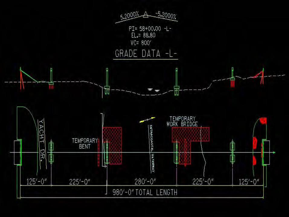
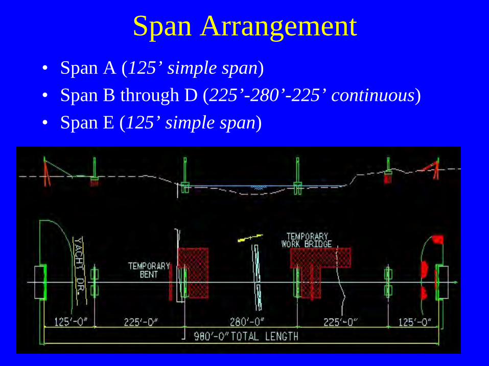
Span Arrangement• Span A (125’ simple span)• Span B through D (225’-280’-225’ continuous)• Span E (125’ simple span)
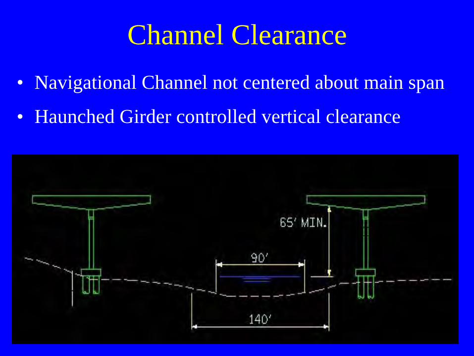
Channel Clearance• Navigational Channel not centered about main span
• Haunched Girder controlled vertical clearance

Typical Section
Concrete Deck
• 8 1/2” thickness (lightweight concrete)
• Removable forms for channel spans
• 3” clear cover– additional corrosion protection– facilitate grinding of the deck
• Epoxy coated reinforcing steel and supports
• Concrete contains calcium nitrite and fly ash

Intermediate Diaphragm• Metallized for corrosion protection• Used on 78” Bulb Tee and Modified 78” Bulb Tee

Intermediate Diaphragm• Metallized for corrosion protection• Used on Haunched Girders

Girder Design
Analysis• Load Factor Design
• Time-Dependent Staged Construction software– IDS BD2 (Presto)– Tango– Consplice®
– Others
• Software selected– Consplice® by LEAP Software, Inc.
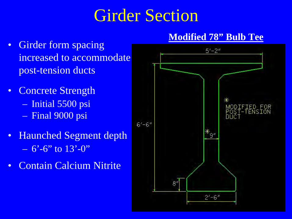
Girder Section• Girder form spacing
increased to accommodatepost-tension ducts
• Concrete Strength– Initial 5500 psi– Final 9000 psi
• Haunched Segment depth– 6’-6” to 13’-0”
• Contain Calcium Nitrite
Modified 78” Bulb Tee

Spliced Girder Segments• One continuous girder line consists of 5 segments
– 2 End Segments 163’-6” 108 tons– 2 Haunched Segments 118’-0” 105 tons– 1 Drop-in Segment 158’-0” 104 tons

Construction Stages for Computer ModelStaging Detail
Slow Paced Fast Paced1 Cut strands 2 12 Erect Haunched Girders 365 603 Erect End Segments 365 604 Erect Drop-in Beams 375 705 Cast closure splices 385 806 Post Tension (Stage 1) 400 947 Cast Deck Slab 460 1248 Post Tension (Stage 2) 480 1319 Cast Rail 490 133
10 Bridge Open to Traffic 550 16311 Future Wearing Surface 4,163 4,16312 Half Life 13,780 13,78013 End of Service 27,560 27,560
75+ year design life
Girder Age in Days

Erection Sequence (Stage 1)• Construct temporary & permanent bents• Erect and secure Haunched Girders

Erection Sequence (Stage 2)
• Erect End Segments• Secure End Segments using strongbacks
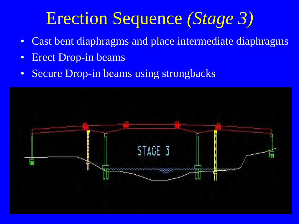
Erection Sequence (Stage 3)• Cast bent diaphragms and place intermediate diaphragms• Erect Drop-in beams• Secure Drop-in beams using strongbacks

Erection Sequence (Stage 4)
• Place remaining intermediate diaphragms• Cast closure splice diaphragms

Erection Sequence (Stage 5)• Complete first stage post-tensioning• Contractor can now erect girders in spans A and E• Cast spans B through D deck

Erection Sequence (Stage 6)• Complete second stage post-tensioning• Cast remaining portions of spans B through D deck• Cast parapet and median

Prestressing Steel• End Segment
– 46 strands, 12 debonded
• Haunched Segment– 38 strands, 6 debonded
• Drop-in Segment– 46 strands, 4 debonded

Build Ups & Deflections• Girder segments are erected as “short chords”
to reduce build ups (Min. build up of 2.5”)– End Segment build up 6.75”– Haunched Segment build up 5.25”– Drop-in Segment build up 7.25”
• More prestressing reduces build up– Watch out for overstressing when PT force
applied
• Temporary tower and bent elevations adjusted– Uplift due to post-tensioning– Haunched girder deflection from drop-in girder

Post-Tensioning Tendons• PT tendons run full length of spans B-D girders
• Three tendons for each girder line
• Tendons contain fifteen 0.6” diameter strands
• Tendons are anchored in End Blocks and stressedfrom both ends
• Intermediate diaphragms are released before firststage of post-tensioning begins

Tendon Profile• PT ducts have an 8” minimum spacing
• Tendons 1 and 2 stressed before casting the deck
• Tendon 3 stressed after casting the deck
• Tendon 3 height increased to reduce stressed in concrete
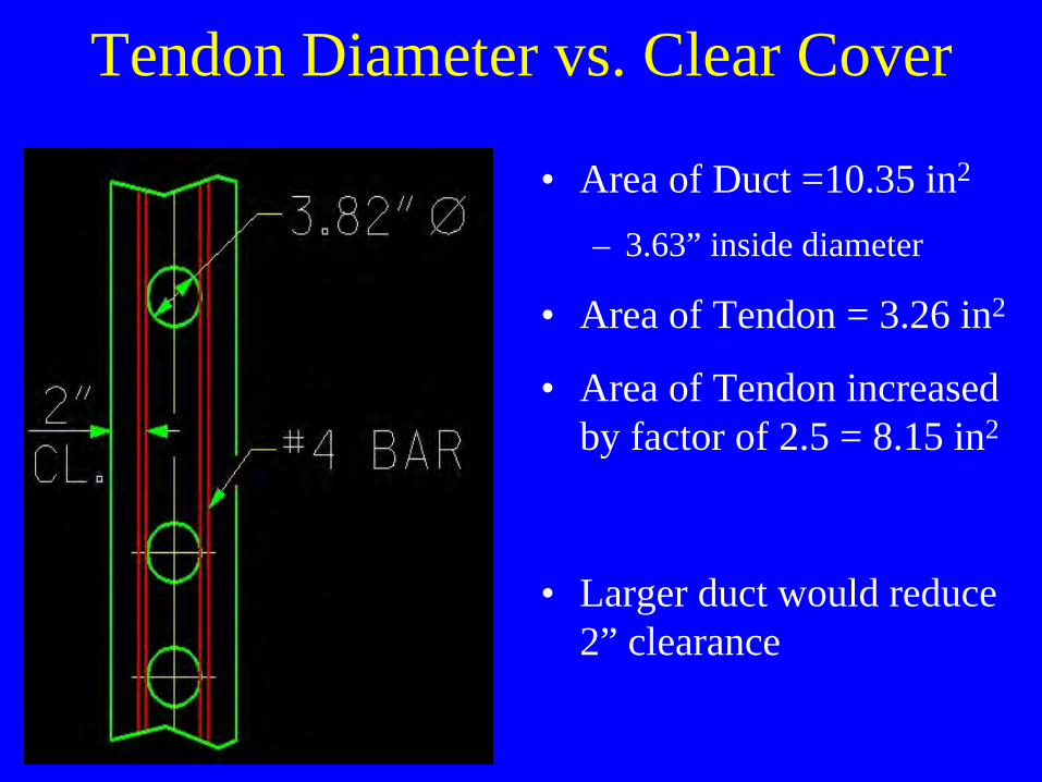
Tendon Diameter vs. Clear Cover
• Area of Duct =10.35 in2
– 3.63” inside diameter
• Area of Tendon = 3.26 in2
• Area of Tendon increasedby factor of 2.5 = 8.15 in2
• Larger duct would reduce2” clearance

End Block Section
• Investigated multiple post-tensioning supplierrequirements for equipment.
• Selected a system supplier
• Sized and located recessesbased on that suppliersneeds.

End Block Elevation View

Corrosion Protection• PT ducts are sealed until tendon placement
• Ducts are cleaned using air
• Water soluble oil is not allowed as a lubricantfor tendon placement
• Anchorages in end block are protected– Recesses are backfilled with non-shrink grout– Grout filled recesses are sealed– End of girder is encased with concrete diaphragm

Lessons Learned
• Placed a diaphragm at the closure splices
• Used approved pre-packaged grout
• Did not use epoxy coated rebar in girders
• Placed post-tensioning tendons in the web– Reduces potential corrosion problems– Reduces end block size for PT anchorage