Embed Size (px)
Citation preview

SECAPConveyor TC72 / Dryer TD72
4/08
Assembly, Operation & Parts ManualSecond Edition

SPECIFICATIONS 1UNPACKING 1ASSEMBLY 2SETUP & OPERATION 6ELECTRICAL SCHEMATIC 8CONVEYOR PARTS 9OPTIONAL 2K DRYER PARTS 13
TABLE OF CONTENTS

SPECIFICATIONS
POWER 105/120 VAC 50/60 HZ
MAIN FUSE 15 AMP
SECONDARY FUSE 3 AMP
POWER CONSUMPTION
CONVEYOR @ MAX SPEED NO LOAD .99 AMP
CONVEYOR @ MAX SPEED NO LOAD W/ ONE FAN 1.19 AMP
CONVEYOR @ MAX SPEED NO LOAD W/ BOTH FANS 1.39 AMP
CONVEYOR @ MAX SPEED NO LOAD W/ BOTH FANS AND DRYER 12.0 AMP
BELT SPEED VARIABLE 30 TO 350 FT PER MINUTE
FAN C.F.M. 170 C.F.M. EACH
HEIGHT ADJUSTABLE 28” TO 35” FLOOR TO TRANSPORT BELT
LENGTH 89”
WIDTH 14”
DROP TRAY ADJUSTABLE 5.2’, 7.2”, 9.2” & 11.2” TRANSPORT BELT TO STACKING SURFACE
WEIGHT 167 LBS (INCLUDES ACCESSORIES)
1
UNPACKING
INSPECT FOR SHIPPING DAMAGE, MISSING PARTS AND PROPER OPERATION. REPORT SHIPPING DAMAGE TO THE CARRIER IMMEDIATELY. SAVE THE SHIPPING CARTONS AND MATERIALS IN CASE THEY ARE NEEDED TO FILE A SHIPPING CLAIM OR FOR FUTURE SHIPPING USE.
1. Check the outside of the carton for visible damage. Make note of any damage on the carriers receiving report.
2. Open the carton.
3. Carefully remove the carton contents and inspect the unit for paint and structural damage.
4. Carefully check for missing parts. If damage or missing parts are noted, contact your Sales Representative immediately. Save cartons and packing materials. They may be required to substantiate a damage claim or to return a damaged unit.

ASSEMBLY
1. Install 2 swivel casters on each of the leg assemblies (Fig 1 & Fig 2 item A). Secure casters with hex nuts.
2. To pre-adjust leg assemblies to proper length, measure the distance from the fl oor, to the exit surface of the delivery device (i.e. printer). Loosen the black hand wheels (Not Shown) (fi gure 1 and 2 item B) and adjust leg assembly until overall length, including casters, is about 7 inches less then the measurement you just obtained. Tighten hex nuts. Repeat procedure for other leg assembly
3. Knock down bracket assembly (fi gure 1 item C) - for install, temporarily install the envelope knock down post (fi gure 1 item D) in the down position, as shown below, use thumb screw and securing plate to attach the post to the bracket.
4. Install envelope knockdown assembly onto one of the leg assemblies (Fig 1 item C) using 2 each Phillips head machine screws provided in accessory bag.
5. Install “L” bracket onto the 2nd leg assembly (Fig 2 item C) using 2 each Phillips head machine screws provided in accessory bag.
A
B
C
Fig 1Fig 1
A
B
C
Fig 2
Securring platePost in down position Thumb screw
D
22

6. With conveyor laying upside down; install leg assembly, with envelope knock down bracket (Fig 1), onto infeed end (end with fans) of conveyor using 4 Socket head Allen screws. Be careful not to bend rail tabs, pictured below, when maneuvering the conveyor while it is upside down.
Assembly Tip: If you have trouble aligning the screw holes in the leg assemblies with the conveyor holes; loosen the 10 Phillips head screws that secure the bottom plate, shown below, to allow the conveyor side frames to fl ex. When fi nished securing leg assemblies to conveyor, be sure to re-tighten these 10 Phillips head screws.
Important! Please be sure the leg assemblies are completely assembled, as described in steps 1 through 5, before proceeding to the next step.
Be careful not to bend rail tabs To help align holes, when attaching leg assemblies, loosen screws that secure bottom plate.
Conveyor shown upside down with legs attached
Fig 3
AA
InfeedInfeed(with fans)(with fans)
3

7. With conveyor laying upside down; install leg assembly, with “L” bracket (Pg 2, Fig 2), onto exit end of conveyor using 4 Socket head Allen screws and lock washers, provided.
Note: Conveyor can be purchased setup to run “Left to Right” or “Right to Left” Make sure the legs are installed on the appropriate ends of the conveyor. A “Left to Right” conveyor is pictured below.
8. With the legs securley fastened, carefully turn conveyor upright. CAUTION! Two (2) people are required for lifting and turning conveyor.
9. Loosen envelope knock down post just enough to allow it to be pivoted and properly positioned, as shown below. Don’t loosen the thumb screw too far or the securing plate will fall off the end of the screw. Tighten the thumb screw to secure the post.
10. Install adjustable height drop tray (fi gure 4 item B) into slots in leg assembly (fi gure 4 item A).
11. Install envelope stop plate (fi gure 4 item C) onto drop tray using 2 hand wheel nuts provided.
12. Place envelope defl ector (fi gure 4 item D), magnetically mounted, onto wall of leg assembly. The envelope defl ector helps prevent material from fl ipping over as it drops into the drop tray. It is not needed in all cases.
13. Place envelope side guides (fi gure 4 item F), magnetically mounted, onto drop tray.
E
C
D
A
B
F
Fig 4
Post in proper position
Post lowered for assembly
4

A
14. Install exit wheel assembly (Fig 5 item A) between rails of conveyor; align with mounting holes and secure in place with 2 grey phillips head screws provided. The wheels can be repositioned anywhere along the rod to meet your specifi c needs.
C
B
A
15. Install threaded end of envelope knock down rod (Fig 6 item B) into hole of envelope knock down post (Fig 6 item C). Install 1 grey Phillips head screw through post and into threaded rod. Install envelope knock down guide (Fig 6 item A) onto rod, as shown above, and secure using thumb screw. Warning! Be sure the bottom of the envelope knock down guide does not rub against the belt or damage to the belt may result.
Fig 5
Fig 6
5

1. Place completed conveyor assembly behind delivery device (i.e. printer) with fans centered on exit end of delivery device.
2. The top of the front guide rail (Fig 7 item A), should be positioned about 1 inch below the exit surface of the delivery device (i.e. printer). If height adjustment is necessary, have another person support the weight of the conveyor while you carefully a). Loosen the black hand wheels (Not Shown) (Fig 1 and 2 item B) and adjust the height of the conveyor leg assemblies. Tighten the Hex nuts to secure the conveyor at the desired height.CAUTION! Be careful when performing this procedure. The conveyor is heavy and can cause injury if not properly supported.
16. Mounting Optional 2K Dryer (shown below) - Slide mounting rods through holes in dryer. Place dryer and rods Mounting Optional 2K Dryer (shown below) - Slide mounting rods through holes in dryer. Place dryer and rods Mounting Optional 2K Dryerbetween rails of conveyor, align with mounting holes and secure in place with the 4 grey phillips head screws supplied (mounting rods, screws and electric components supplied in dryer box). Connect the dryer’s power cord to the outlet on back of the conveyor. CAUTION! Do NOT connect dryer to a separate power source or dryer damage may result. Connect dryer power cord to outlet on conveyor, as shown below.
A
Mounting Rods
Optional 2K Dryer
SETUP & OPERATION
Fig 7
6
3. Connect conveyor power cord to an earth grounded, 105/120 VAC, 50/60 Hz electrical source.
4. Set up delivery device (i.e. printer) for desired media.
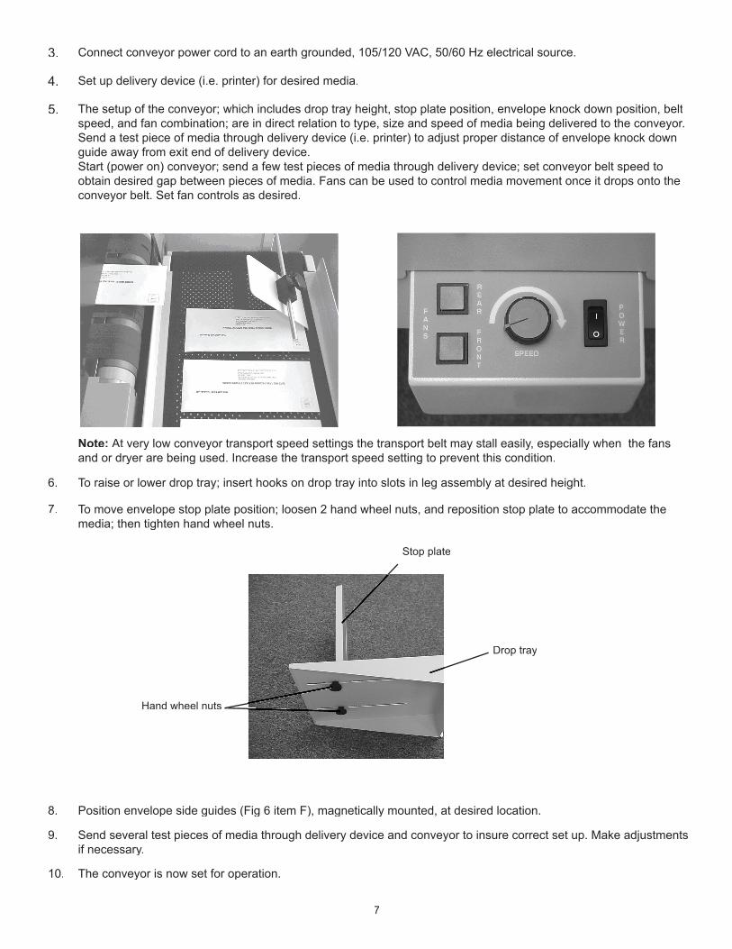
5. The setup of the conveyor; which includes drop tray height, stop plate position, envelope knock down position, belt speed, and fan combination; are in direct relation to type, size and speed of media being delivered to the conveyor. Send a test piece of media through delivery device (i.e. printer) to adjust proper distance of envelope knock down guide away from exit end of delivery device. Start (power on) conveyor; send a few test pieces of media through delivery device; set conveyor belt speed to obtain desired gap between pieces of media. Fans can be used to control media movement once it drops onto the conveyor belt. Set fan controls as desired.
Note: At very low conveyor transport speed settings the transport belt may stall easily, especially when the fans and or dryer are being used. Increase the transport speed setting to prevent this condition.
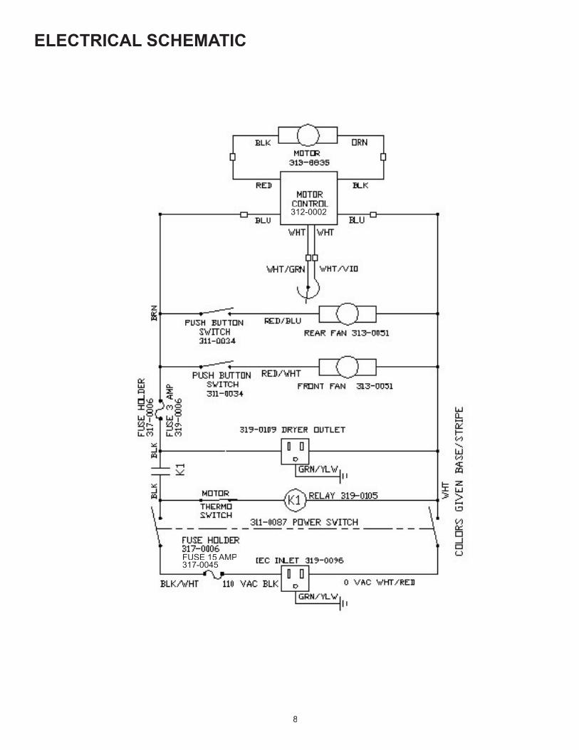
6. To raise or lower drop tray; insert hooks on drop tray into slots in leg assembly at desired height.
7. To move envelope stop plate position; loosen 2 hand wheel nuts, and reposition stop plate to accommodate the media; then tighten hand wheel nuts.
8. Position envelope side guides (Fig 6 item F), magnetically mounted, at desired location.
9. Send several test pieces of media through delivery device and conveyor to insure correct set up. Make adjustments if necessary.
10. The conveyor is now set for operation.
Stop plate
Hand wheel nuts
Drop tray
7
ELECTRICAL SCHEMATIC
8
312-0002
FUSE 15 AMP317-0045

CONVEYOR PARTS
ITEM PART # DESCRIPTION QTY.1 395-0699 ROLLER ASSY. PLASTIC 22 365-0164 TIMING BELT LO50 13 365-0163 TIMING PULLEY 9T 14 313-8835 1/6 HP MOTOR 15 312-0002 SPEED CONTROL 16 319-0105 RELAY 1 HP 55 AMP INRUSH 17 311-0034 ALTERNATE ACTION SWITCH 28 319-0031 POTENTIOMETER 19 311-0087 ROCKER SWITCH DPST 1
10 313-0051 FAN 115 VAC 170 CFM 211 310-0179 WIRING HARNESS 112 317-0006 SHOCK-SAFE FUSE HOLDER 213 317-0045 15 AMP FUSE 114 319-0109 IEC-320 POWER OUTLET 115 319-0096 RECPT. RECESSED POWER 116 319-0006 3 AMP SLOW-BLOW FUSE 1
6
5
11
2
3
4
1213
14
7 8 9
1216
15
10
11
9

ITEM PART # DESCRIPTION QTY.1 376-0077 8-32 SET SCREW 42 380-5538 NYLON PELLET 33 361-8136 STACKER WHEEL ARM 24 320-0011 WEIGHTED STACKER WHEEL 25 332-0139 SHAFT, STACKER WHEEL 16 373-0106 PPH, SCREW 10-32 PB SPL 37 330-8137 WHEEL AXLE 28 369-0035 TRANSPORT BELT 19 395-0902 THUMB SCREW ASSY. 1
10 360-1837 PLATE KNOCK DOWN 111 334-0367 ADJ. BLOCK KNOCK DOWN 112 323-0028 TUBE END CAP 1x1 113 332-0137 SHAFT, KNOCK DOWN 114 360-1836 POST KNOCK DOWN 115 360-1860 BRKT. KNOCK DOWN ADJ. 116 395-0903 HAND SCREW ASSY. 117 378-0128 ¼-20 T NUT 118 379-0013 PUSH ON CLIP 1
12 3 45
67 8
29 11 10
12
13
14
15161718
10

ITEM PART # DESCRIPTION QTY.1 372-0059 SWIVEL CASTER 42 378-7006 5/16-18 HEX NUT 43 360-2256 UPPER LEG 24 360-1857 LOWER LEG 25 377-0069 FLAT WASHER 46 378-0129 ½-13 HEX NUT 47 373-0096 PPH SCREW 10-32 48 360-1858 EXIT BRACKET 1
385-0059 LEG/CASTER WRENCH(NOT SHOWN) 1
3
76
4
12 5
12
1
2
3
1
2
4
7
8
56
11
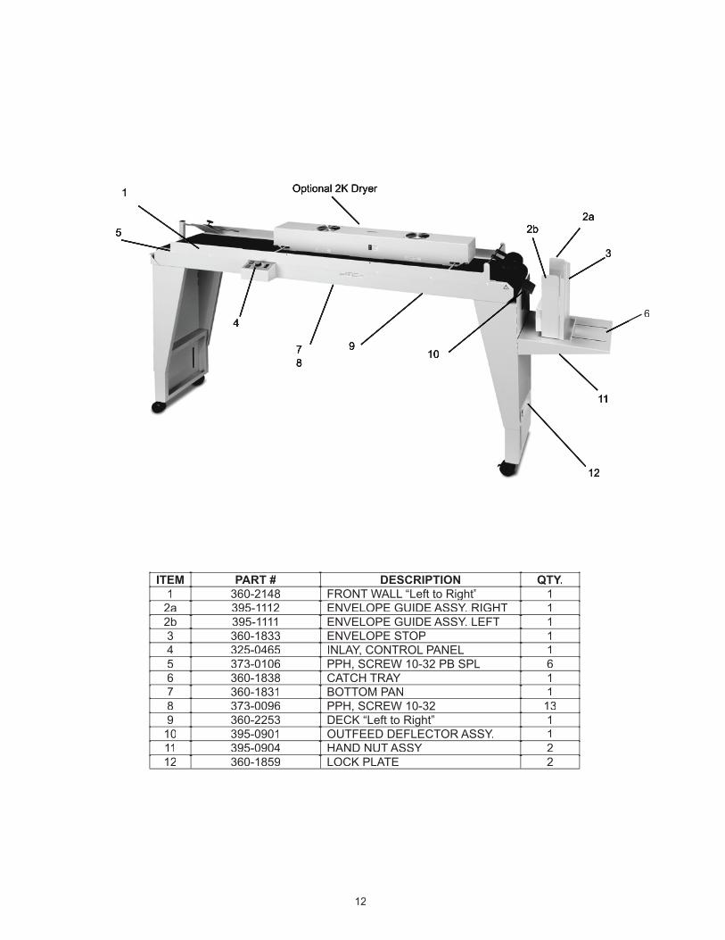
ITEM PART # DESCRIPTION QTY.1 360-2148 FRONT WALL “Left to Right”FRONT WALL “Left to Right” 1
2a 395-1112 ENVELOPE GUIDE ASSY. RIGHT 12b 395-1111 ENVELOPE GUIDE ASSY. LEFT 13 360-1833 ENVELOPE STOP 14 325-0465 INLAY, CONTROL PANEL 15 373-0106 PPH, SCREW 10-32 PB SPL 66 360-1838 CATCH TRAY 17 360-1831 BOTTOM PAN 18 373-0096 PPH, SCREW 10-32 139 360-2253 DECK “Left to Right”“Left to Right” 1
10 395-0901 OUTFEED DEFLECTOR ASSY. 111 395-0904 HAND NUT ASSY 212 360-1859 LOCK PLATE 2
11
12
10
55
9
4
1 Optional 2K Dryer
2a
3
78
12
6
2b
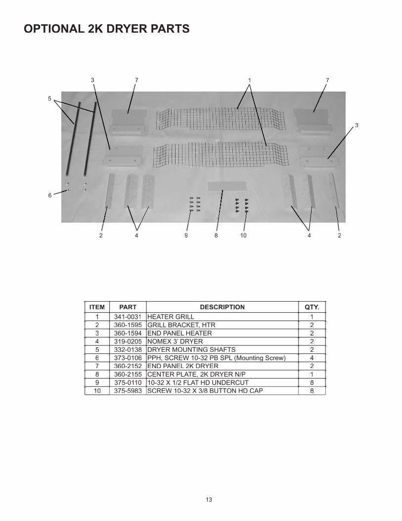
ITEM PART DESCRIPTION QTY. 1 341-0031 HEATER GRILL 12 360-1595 GRILL BRACKET, HTR 23 360-1594 END PANEL HEATER 24 319-0205 NOMEX 3’ DRYER 25 332-0138 DRYER MOUNTING SHAFTS 26 373-0106 PPH, SCREW 10-32 PB SPL (Mounting Screw) 47 360-2152 END PANEL 2K DRYER 28 360-2155 CENTER PLATE, 2K DRYER N/P 19 375-0110 10-32 X 1/2 FLAT HD UNDERCUT 8
10 375-5983 SCREW 10-32 X 3/8 BUTTON HD CAP 8
OPTIONAL 2K DRYER PARTS
13
5
6
4 2
3
73
2 4
17
89 10
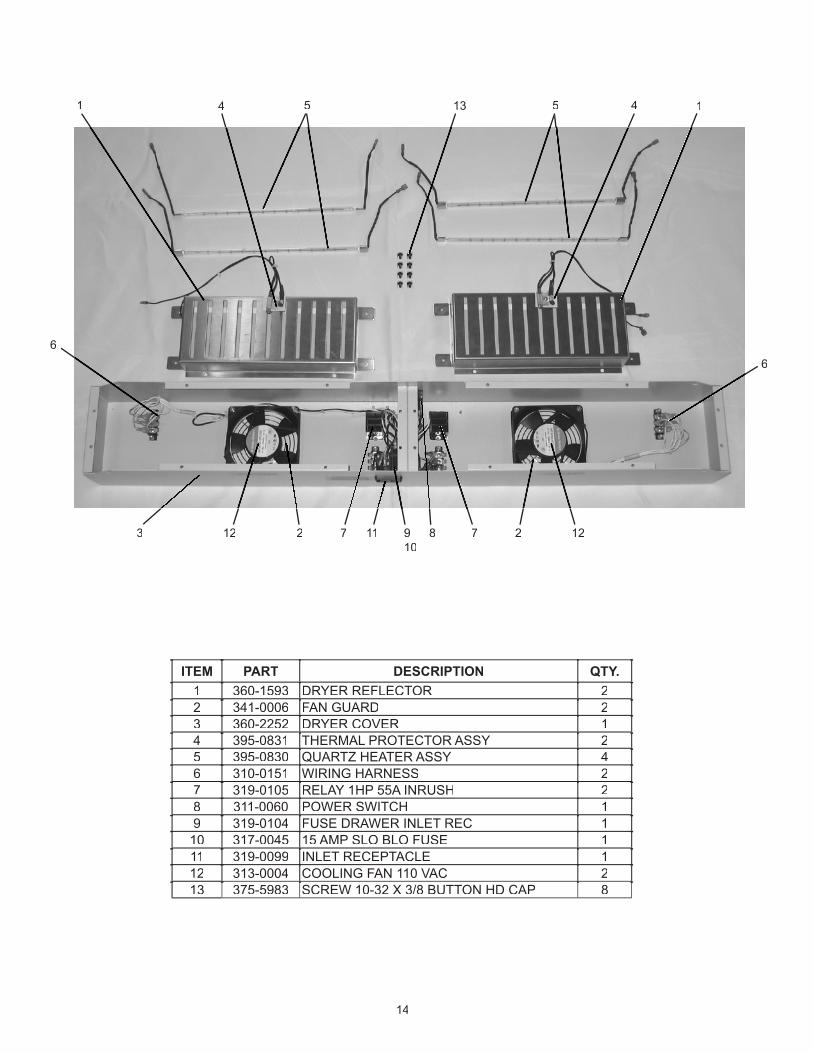
ITEM PART DESCRIPTION QTY. 1 360-1593 DRYER REFLECTOR 22 341-0006 FAN GUARD 23 360-2252 DRYER COVER 14 395-0831 THERMAL PROTECTOR ASSY 25 395-0830 QUARTZ HEATER ASSY 46 310-0151 WIRING HARNESS 27 319-0105 RELAY 1HP 55A INRUSH 28 311-0060 POWER SWITCH 19 319-0104 FUSE DRAWER INLET REC 1
10 317-0045 15 AMP SLO BLO FUSE 111 319-0099 INLET RECEPTACLE 112 313-0004 COOLING FAN 110 VAC 213 375-5983 SCREW 10-32 X 3/8 BUTTON HD CAP 8
910
11 122
6
3
14 5
78
14
12 2
6
7
1 5 413