Embed Size (px)
Citation preview


Installation Manual
Document SCS-IM/M4B-175/400-2018 Page | - 1 -
Copyright Seatorque Control Systems LLC - © - all rights reserve
M4B SERIES SEATORQUE SHAFT SYSTEM
General Installation
INTRODUCTION
This Manual covers the “M4B” series of shaft
system. M4B systems are designed to fit vessels
where the shaft exits the hull through a shaft Pocket
or Alley
The manual is provided as a step by step procedure
for the correct method of installation, the assumption
is made that the Shaft Pocket is already in place and
sized per the supplied engineering drawings for the
system ordered and therefore only addresses the
actual system installation.
Please refer to page 3 in this manual which outlines
the tools that may be required to successfully
complete the installation.
M4B-Series Shaft System and Shaft Pocket

Installation Manual
Document SCS-IM/M4B-175/400-2018 Page | - 2 -
Copyright Seatorque Control Systems LLC - © - all rights reserve
Section 1. PRE INSTALLATION GUIDE
Section Title
1) Pre Installation Guide.
2) Approaches to installation.
3) Strut or “P” bracket – pre-installation and alignment.
4) Preparation of the system for installation.
5) Step by step installation instructions.
6) Installing the Propeller Seal carrier
7) Fastening the casing with SCS M4B shaft support Bracket, Post 2016 Method.
8) Setting the casing in “P” strut or “V” Bracket Pre 2016 Injection Method.
9) Installation of Oil Tank and hoses.
10) Installation of Transmission Adapter
11) Alignment of Cardan Shaft
12) Installation of Cardan Shaft
13) Bolts that carry Torque and Those which require a Thread Locker.
14) Oiling the System.
15) Galvanic Bonding of the System.
16) Painting the System.
17) Post Installation Notes.
18) Final Installation OEM Check and Sign Off.
19) Addendum
Please take the time to read this manual thoroughly before attempting any work on the shaft system.
Do not change the recommended order of installation as certain components may only be successfully
installed in the manner described.

Installation Manual Continued
Document SCS-IM/M4B-175/400-2018 Page | - 3 -
Copyright Seatorque Control Systems LLC - © - all rights reserve
Section 2. APPROACHES TO INSTALLATION
NOTE: Dirt is the enemy of a reliable machine, practice cleanliness at all times, keep all components
stored in clean areas, sealed bags or wrapped in clean protective material prior to and during
installation. Keep all components in heat shrink packaging until ready to install. Examine each
component for dirt contamination prior to installation, clean before installation as needed.
WHAT YOU WILL NEED TO BEGIN INSTALLATION.
Please make sure you have the following items prior to the installation of your system to ensure a
smooth process.
1) Seatorque Shaft System Installation Manual.
2) Engineering Drawings prepared by Seatorque for the Specific Vessel and shaft system
(to verify measurements and placements).
3) Seatorque supplied bolting pattern drawing template or optional drilling fixture.
4) For aligning the strut to the shaft line, a suitable Length of Schedule 40 Aluminum or
PVC pipe, equal to the diameter of the shaft casing of the system being installed.
(This should become a permanent installation fixture for future use).
5) Torque Wrench – see attached fastener application/tool requirement guide for size.
6) Allen Wrenches– see attached fastener application/tool requirement guide for size.
7) Socket set, Open/Ring or Combination Wrenches/spanners – assorted Metric and
Imperial Sizes.
8) Pipe wrench or Stilson wrench, suitable to fit the casing diameter of the ordered system.
Note: required to properly torque the casing after installation.
9) Straight edge & set square – to Check Alignment of U-Joints and Strut.
10) Loctite™ or equivalent - RED Permanent high strength thread locker– for Propeller Seal
Carrier Bolts.
11) 3M- 5200™ Fast Cure Urethane Marine Adhesive Sealant or equivalent – for Isolator
backing Ring studs and Shaft Casing Threads. (See Footnote).
12) SCS Full Synthetic Gear Oil 75w-90, API-GL5. OR Optional SCS SAE 150 Fully
Biodegradable, Eco-friendly Shaft lubricant (Shipped with system).
Footnote:
Any suitable/equivalent Poly-Urethane Marine Adhesive can be used for this application as it is
only used to seal the main casing threads from water intrusion as well as to seal and set the nuts and
washers on the Isolator Mounting studs.
The SEATORQUE shaft system is composed of pre-assembled components. These assemblies are
designed to make the installation of the system as simple and straight forward as possible. To
preserve the Factory Warranty some components are sealed ready for installation to the vessel. To
ensure a successful installation, please take care to install these components in the order outlined in
this manual.

Installation Manual Continued
Document SCS-IM/M4B-175/400-2018 Page | 4
Copyright Seatorque Control Systems LLC - © - all rights reserve
Section 2. Approaches to Installation Continued
COMPONENT ASSEMBLY IDENTIFICATION
Thrust Housing Assembly
Front Seal retaining Ring
Shaft Coupling
Shaft Coupling Bolt
Shaft Coupling Washer
Isolator Mount
Isolator Backing Ring
Isolator Bushings (2)
Thrust Housing
Mounting Flange Shaft Splined End
Shaft casing Assembly
Casing Locking Ring
Line Cutter Holder
Seal Carrier
Shaft Taper End
Propeller housing Mounting Flange
Propeller Housing

Installation Manual Continued
Document SCS-IM/M4B-175/400-2018 Page | 5
Copyright Seatorque Control Systems LLC - © - all rights reserve
Section 3. STRUT (“P” BRACKET) PRE-INSTALLATION AND ALIGNMENT.
In all cases the strut should be pre-set prior to system installation. This is a large advantage in a
production environment but also should be contemplated on a one-off basis as it provides simplicity
of installation.
Again it is assumed in this manual that all mounting preparation work has already been undertaken
and that the thrust bulkhead has already been prepared for system installation. It should be noted that
traditional methods of identifying shaft Center Line is not necessary for the simple installation of a
Seatorque shaft system.
Sch 40 Pipe
The tool used to align the strut is a length of Schedule 40 pipe the same size as the casing of the shaft
system being installed and long enough to span through the strut and forward through the face of the
shaft Pocket (Please refer to the specification page where System Casing Dimensions are listed).
Place strut in position on hull, insert one bolt on each side of strut palm to attach strut loosely to hull.
Slide the section of pipe through the strut and into the main center hole in shaft pocket. Referring to
illustration of “proper strut alignment”, note that the objective is to make the pipe lie flat along the
bottom surfaces of the strut barrel, and checked with a suitable square be perpendicular (90 degrees) to
the thrust bulkhead or pocket mounting face. Install the 4 set screws (if fitted) in the threaded holes of
the strut palm to allow the strut to be fine adjusted and permanently positioned without losing shaft
alignment.
Remove pipe from strut, lower strut from hull and apply bedding compound as per normal mounting
practice and re-install strut to hull. Insert all bolts up through strut and through hull structure. Snug
bolts loosely until 4 set screws contact the mounting surface. Slide alignment pipe back into position
and final check alignments, make adjustments necessary to achieve the correct parameters.
Remove alignment pipe and allow strut to set permanently. Clean up bedding around strut palm and
once set, remove the 4 set screws. Fair the strut palm to hull. Providing that all conditions in “strut
alignment drawing” have been met, the strut is now successfully installed.

Installation Manual Continued
Document SCS-IM/M4B-175/400-2018 Page | 6
Copyright Seatorque Control Systems LLC - © - all rights reserve
Section 4. PREPARATION OF THE SYSTEM FOR INSTALLATION
All Seatorque shaft systems are assembled in a clean environment at the Seatorque factory and shipped
“dry” assembled as a unit with both ends shrink wrapped for protection. After removal of the system
from the shipping crate, certain pre-assembled components must be removed. These are described step
by step below. Remove all hardware boxes, these are individually identified, the contents being outlined
on the master packing list included with each shipment. Please verify that all components and hardware
is complete as listed, also please note carefully if any components are marked as back-ordered which
might affect scheduled installation of the system.
1) Remove the protective shrink plastic from thrust bearing end of the shaft system taking care not
to damage the cosmetic finish of the housing surface.
2) Make sure that the propeller end of the shaft is secure and cannot slide out of the casing
assembly. The shaft and casing is assembled in a dirt free environment and it is, if possible
recommended that the shaft remains inside the casing during installation. Should it be necessary
to remove the shaft for any reason, care must be exercised to keep the components free from
contamination, dust or debris before re-assembly.
3) Remove the Bolt in the center of the shaft
coupling. Note: RH Thread.
4) Remove the coupling from the splined shaft
end, place in a clean area and cover ready for
re-installation.

Installation Manual Continued
Document SCS-IM/M4B-175/400-2018 Page | 7
Copyright Seatorque Control Systems LLC - © - all rights reserve
Section 4. PREPARATION OF THE SYSTEM FOR INSTALLATION - Continued
5) Remove all nuts & washers holding the thrust housing in place
to the Isolator Mount Bolting Flange. Slide the thrust housing
assembly off the end of the splined shaft. Wrap the housing
in a protective cover and place in a clean area until required,
thrust bearings are inside the housing and therefore attention
to cleanliness is imperative.
6) Unthread and remove the Isolator Mount completely from the
shaft casing (Starboard RH and Port LH thread). Undo the nuts and washers on the isolator
studs, and slide the Backing Ring and Bushing from the mount.
7) Unthread the locking ring from the casing (Port LH Thread, Starboard RH Thread).
Section 5. Step by Step Installation of the System
1) Protect the exposed Casing threads from damage with masking
tape or similar. Slide the casing and shaft assembly through the
pre-installed strut/bracket.
2) Thread the Casing Locking Ring onto the Casing end and thread
back gently as far as it will go.
3) Continue to slide the casing forwards until
it is close to the hull pocket
4) Apply Polyurethane Marine Adhesive to
casing threads on the inboard end of the
shaft/casing assembly. Spread the 5200
evenly over the surface of the threads
completely through 360 Degrees.
Note: Casing has a machined nose with flat face finish designed to
mate with a seat in the isolator Housing providing a positive seal
when tightened, an O-ring is also included to ensure a permanent
seal.
The 5200 is necessary to seal threads against water intrusion and possible crevice corrosion.

Installation Manual Continued
Document SCS-IM/M4B-175/400-2018 Page | 8
Copyright Seatorque Control Systems LLC - © - all rights reserve
Section 5. Step by Step Installation of the System - Continued
The following step is done from inside the engine room of the vessel.
5) Slide the threaded end of the Isolator Mount with inner
Urethane Bushing through the main center hole in the pocket
face.
6) Outside the vessel, install the
outer urethane bushing over
the studs and firmly up against
the pocket face. (See Note 2.)
7) Apply a thick bead of 5200
Marine Adhesive sealant around base of each stud.
8) Install the Isolator backing ring over studs and up against the
urethane bushing.
9) Bead around the studs with 3M-5200 and Install the spring washers
and nuts loosely to the studs. (See note 1.)
Note 1: It is important that the isolator is free to move, this will aid in alignment and installation
of the shaft casing.
Note 2: Do not apply 5200 Marine adhesive sealant to the bushings and/or pocket faces, doing so
may promote leaks or early failure of the isolator bushings.
10) Thread the casing into the Isolator Mount until it
stops metal to metal.
11) Final tighten all nuts to the correct torque settings
and tightening sequence outlined in the shaft torque
sheet and sequence bulletin in the back of this
manual using a correctly calibrated torque wrench.
When correctly tightened the walls of the bushing
should show a small amount of bulge no more than 1/16”
(1.5mm).
NOTE: See tightening sequence diagram at the back of this manual next to torque settings

Installation Manual Continued
Document SCS-IM/M4B-175/400-2018 Page | 9
Copyright Seatorque Control Systems LLC - © - all rights reserve
Section 5. Step by Step Installation of the System - Continued
12) Place a pipe wrench (Stilson) on the casing as close as possible
to the isolator mount and tighten the casing to the isolator until
it stops metal to metal.
13) On the casing, mark a register line. Final torque of the system
casing is achieved by turning the casing a set distance beyond
this reference mark. This dimension is listed in the casing
sheet at the back of this manual, it can also be calculated from
the circumference of the casing OD, divided by 360, the result
is then multiplied by 7. The resultant number is the distance
the casing must move to achieve 7 degrees past the register
line.
14) Mark the destination line measured from the register line, place the pipe wrench back on the
casing and turn until the two marks line up. It may require considerable force to achieve this
setting. Take care not to distort the casing.
Note: The illustration shows a Port shaft Casing, port shaft casing is Left Hand thread, Starboard is
Right Hand thread.
15) Check point; Make sure that the O-ring Seal is in the
groove machined on the face of the Thrust Housing
Mounting Flange as shown.
Note: The system is shipped with a spare O-ring in the hardware
box in case of loss or damage.

Installation Manual Continued
Document SCS-IM/M4B-175/400-2018 Page | 10
Copyright Seatorque Control Systems LLC - © - all rights reserve
Section 5. Step by Step Installation of the System – Continued
16) Check point; Make sure the Oil Impeller O-ring seal is
installed in the groove provided inside the bore of the bearing
housing as shown.
Note: The system is shipped with a spare O-ring in the
hardware box in case of loss or damage.
17) Pre-oil spline and shoulder of shaft thoroughly with Shaft
Oil; also making sure that the bore of the Thrust housing and
O-ring are well lubricated.
18) With the oil ports aligned to the top, slide the Thrust Housing
Assembly onto the shaft, the mounting studs will slide
through the holes in the Isolator Bolting Flange, push housing
firmly up against the flange
making sure that main O-ring seal
is correctly seated (a very small
gap will be visible between the
isolator flange and the thrust
housing, this is due to the O-ring
projection, and will close up once
the nuts and washers are installed
and tightened.

Installation Manual Continued
Document SCS-IM/M4B-175/400-2018 Page | 11
Copyright Seatorque Control Systems LLC - © - all rights reserve
Section 5. Step by Step Installation of the System - Continued
19) Check point, Make sure that the coupling O-ring is installed in the groove provided inside the
back end of the coupling.
Note: A spare O-ring is shipped in the hardware
box with the system in case of loss or damage
20) Lubricate the internal and
external splines of
coupling and shaft with
Seatorque shaft oil.
21) Lubricate the outside of the Shaft Coupling barrel surface
where the oil seal rides, carefully engage the
shaft/coupling splines and push Shaft Coupling firmly
home against bearings in Thrust Housing Assembly.

Installation Manual Continued
Document SCS-IM/M4B-175/400-2018 Page | 12
Copyright Seatorque Control Systems LLC - © - all rights reserve
Section (5). Step by Step Installation of the System - Continued
22) Lubricate the threads of the Main Coupling Bolt with shaft
oil and install Shaft Bolt and Coupling Washer to end of
shaft. Hand tighten bolt until it is snug against the coupling.
23) Important:
Tighten the bolt to the correct Pre Torque and then
Final torque settings using a properly adjusted
Torque wrench.
Settings are shown at the back of this manual on the Shaft
specification page. It is mandatory that the specifications
for any of the bolts outlined in this manual are applied
exactly as called for, not enough torque will de-rate the
shaft specifications, and too much torque, may cause
internal damage.
NOTE: DO NOT USE LOCTITE™ WHEN INSTALLING THE SHAFT COUPLING BOLT.

Installation Manual Continued
Document SCS-IM/M4B-175/400-2018 Page | 13
Copyright Seatorque Control Systems LLC - © - all rights reserve
Section 6. INSTALLING PROPELLER SEAL CARRIER
a) Remove the seal Carrier from its protective shrink wrap.
b) Make sure both seals are properly aligned in the
carrier; the seals are shipped already greased,
however visually check that the grease is as
illustrated in fig.2, if not, apply general purpose
Synthetic Grease to the space between the two
seals ensuring that the grease is level with the lips
of the two seals.
Fig. 2
c) Apply a film of grease or shaft oil to the O-rings
on the outside nose of the carrier.
d) Install the Seal Carrier over the shaft taper and
after aligning the bolt holes, push the carrier
firmly home into the Propeller Housing.
NOTE: The Cutter Blade relief must be positioned
directly under the cutter holder at the 12:00 o’clock
position
Make sure that the water injection port is positioned to
the Left or Right side of the housing.
e) Install the Stainless Steel Allen head bolts with Red Loctite™ 271 (or Blue 2701) and snug home.

Installation Manual Continued
Document SCS-IM/M4B-175/400-2018 Page | 14
Copyright Seatorque Control Systems LLC - © - all rights reserve
Section 7. SETTING THE CASING TO STRUT – 2016 M4 MECHANICAL STRUT GLAND
From 2016 Onwards all strut barrels are of the M4
Mechanical strut mounting type. The strut barrel is
machined to accept multiple 3/8” diameter EPDM
Rubber O-Rings supplied as individual pieces at the
correct length to fit the OD/ID of the Casing and Strut
Barrel. These rings are stacked together to form a
sleeve that is then compressed by a bolted cap which
expands the O-Ring packing gripping the shaft casing
and supporting it within the strut assembly.
This method has been developed by SCS to provide a
more efficient and simpler installation of the shaft
system as well as allow more service options in the
field.
Supplied with the Shaft system will be the required
number of O-Ring strips (Generally between 10 and 15 pieces depending on system size), It is important
that all pieces are installed.
The strut cap is supplied in two halves to allow easy installation/dismantling together with the correct
number of Stainless Steel Allen Head Bolts.
a.) Once the shaft system is installed, take one piece
of the O-Ring, lubricate it with household dish
washing detergent. Wrap it around the shaft
casing at the rear end of the strut barrel and with
the two ends aligned together, push the ring as
far as possible into the cavity in the barrel
(usually far enough to fit the next piece in place).
b.) The next piece of O-Ring should be installed
with the ends 180 Degrees opposed to the first
piece.
c.) Repeat the process until all pieces are installed.
Note: The bolting cap can be used as a tool to
push the O-Rings into the cavity.
Once all the pieces are installed the cap should have a gap approximately 3/8” (9.5mm) or one diameter
of cord stock clearance to the bolting face of the Strut Barrel, this provides sufficient compression to
expand the Rings.
Install both halves of the Bolting Cap aligned to the bolt holes with the joint between the two halves
oriented vertically. Install all the Allen Head bolts and tighten the cap home until it contacts with the
face of the strut barrel. One at a time remove each Bolt and re-install it using High strength LoctiteTM
or equivalent.

Installation Manual Continued
Document SCS-IM/M4B-175/400-2018 Page | 15
Copyright Seatorque Control Systems LLC - © - all rights reserve
Section 8. OPTIONAL METHOD
SETTING THE CASING TO STRUT USING PRE 2016 3M-5200 INJECTED METHOD
If the strut barrel is provided with threaded jacking points and set screws, jack up casing until it is
centered in the barrel. Radial clearance should be approximately 1/8 to a 1/4 of an inch and equal all
around the barrel front and rear. If no jacking points are provided then support the system with blocking
so that it is held centered. Make sure that the inside of the strut barrel and outside of shaft casing are
well misted with clean fresh water, this will aid in curing the 5200 after injection.
Insert a length of 1/8” or 1/4” Rubber O-ring stock into the clearance between casing and strut barrel.
Starting at the top of the barrel and by stretching the O-Ring material to reduce its diameter push into
gap all around the casing until it meets the other end. Cut the O-Ring material leaving a small space
between the ends as a breather hole. Repeat this at the other end of the Strut barrel.
Through the two ¼ inch holes drilled either side of the barrel at the mid-point, inject strut with 3M-5200
FAST CURE. Start injecting on one side until 5200 appears at either end or ¼” injection hole on
opposite side. As this occurs, plug off areas where bedding can escape and inject from opposite side
injection point. Keep injecting until satisfied that all air in the barrel has been displaced.
It is important to leave strut to post cure or until Adhesive (5200) has set before removing jacking screws
or spacers (usually 24 hours to set and 48 Hours for full cure). For safety allow at least 24 hours for full
cure before removing jacking screws. NOTE: Jacking screws must not be left in place permanently as
they will cause wear and ultimate damage to the casing during routine operation of the vessel as well as
create excess noise and vibration.
If Rubber O-ring stock has been used this should be left in place as it provides good protection as well
as a clean finish for the ends of the strut barrel. To final finish, remove any tape, plugs and/or spacers,
and with a sharp knife slice off any protruding 5200 flush with each end of the strut barrel. Remove
jacking bolts and inject jacking locations with 3M-5200™ or install stainless steel pipe plugs to final
seal holes.
NOTE:
3M-5200 is a Polyurethane based Elastomer. It is cured by oxygen and water vapor, i.e. the humidity
or moisture in the air is the catalyst required for it to achieve full cure. Once the container has been
opened the process has started, it may continue to cure even when no longer in contact with the
atmosphere.
Very Important:
Do not use any Alcohol based products to pre clean the area where 5200 is to be injected, alcohol fumes
can neutralize the curing process by eliminating the humidity in the air, please read and follow the 3M
instructions provided in the Addendum section for its use and compatibility.
Alcohol derivatives such as Methyl, Ethyl, Propyl, Isopropyl, Hydroxide, Propane and Methanol can be
found in many solvents. The only safe solvent that can be used is pure Acetone without any additives.
Most paint thinners and surface cleaners, including mineral spirits can contain many of the above
ingredients and therefore should not be used. To help ensure correct cure, spray or mist the inside of
the strut barrel with clean water prior to injection.

Installation Manual Continued
Document SCS-IM/M4B-175/400-2018 Page | 16
Copyright Seatorque Control Systems LLC - © - all rights reserve
Section 9. INSTALLATION OF OIL RESERVOIR TANKS
Oil Tank and hose Installation:
The oil tank is supplied complete with the correct length and diameter of hoses and fittings. Location
of the tank should be as close to the thrust housing as possible with the bottom of the tank above the
connection ports on the thrust housing. Wherever possible the bottom of the tank should be
approximately 12 inches (300mm) to 36 Inches (900mm) above DWL (displacement waterline), this
provides good positive pressure to the shaft system and oil seals. Hoses may be connected to either port
in the bottom of the tank (direction of flow reverses with change in shaft rotation).
It is important that the correct oil flow is maintained to the oil tank as the volume and surface area of
the tank forms a part of the shaft oil cooling capacity during operation.
The tank system flow is designed with two 4 foot Hose runs (supplied as one 8 foot long piece) 4 foot
is the recommended length for the hose diameter and flow characteristics. Location of the tank should
be kept within this hose length wherever possible.
For installations where this is not possible please contact Seatorque factory for application
assistance and plumbing alternatives.
NOTE:
Liquid sealant such as Hydraulic Loctite™ should be used on all NPT pipe threads on the oil tank.
Do Not use sealant of any type on JIC flare fittings on the Thrust Housing ports.
Do Not over tighten JIC flare fittings or they may leak.
Do Not use Teflon or PTFE pipe tape on any connections as pieces of tape can get trapped under shaft
seals causing leakage and/or their premature failure.
DO NOT SUBSTITUTE THE SUPPLIED HOSE WITH ANOTHER TYPE. The supplied hose is Parker
“Pushlok” type 801 hose and is compatible with Seatorque Full synthetic Shaft Oil or optional Seatorque
Fully Biodegradable Oil.
DO NOT USE HOSE CLAMPS or any other type of clamps or clips on the supplied barbed fittings,
“Pushlok” hose fittings are designed to be leak free and withstand pressures of 250 PSI without the use
of hose clamps. Use of clamps will cause leaks and ultimate failure of the hose system.
Maximum Bend Radius is 15 times the hose diameter. Be careful not to install the hoses with less
Bend radius than recommended or restrictions within the hose system will result in inadequate oil flow.
NOTE: Oil coolers are NOT NORMALLY REQUIRED on M3, M4 or M4B series shaft systems.

Installation Manual Continued
Document SCS-IM/M4B-175/400-2018 Page | 17
Copyright Seatorque Control Systems LLC - © - all rights reserve
Section 10. INSTALLATION OF TRANSMISSION ADAPTER
The transmission adapter is bolted to the output flange of the marine gear and adapts the gear output
flange to mate with the Cardan Shaft or Universal Joint driveline assembly. The Adapter is made to
order to suit the make and model of transmission fitted to the vessels main propulsion engines. Please
verify that the adapter is a match to the transmission output coupling.
Remove the Nyloc
self-locking nuts and
flat washers from the
studs of the adapter.
Align the mounting
studs to the bolt
pattern on the gear
output flange, push
home far enough to
install the flat washers and Nyloc Nuts on the back side of the flange. Once nuts are in place push firmly
home. The adapter is a precision machined component designed to mate with high accuracy to the pilot
or mating ring on the Gear output flange. Due to tolerance range sometimes this will mate together
easily and in other cases it will require tightening the nuts at the rear of the flange to pull the adapter
into place. Once this is achieved the faces of the adapter and flange will be hard up against each other
with no measurable gap between them.
Important: Final tighten all nuts evenly and as tight as possible. The nuts are placed in a position on
the transmission flange that generally makes it difficult or impractical to use a torque wrench to tighten
them. Guideline torque values are listed on the torque chart at the back of this manual.
Note: Do not use Loctite™ on the nuts and studs.
Self-locking Nylon type nuts as supplied require flat washers; spring type washers
should not be used.
Applying torque without a torque wrench:
Example: in metric terms a unit of 100Nm (100 Newton/meter), describes a wrench length of one meter
from the centerline of the nut, with a weight of 100 Newton’s applied. Metric torque figures can also
be written in weight/length as Kg/m, Kg/cm, grams/mm etc.
Similarly in Imperial: 100 Ft/Lbs. or 100 Lbs./Ft. describes a wrench length of one Foot (12 inches)
with a weight of 100 Lbs. applied. Imperial torque figures (usually below 20 Ft/Lbs.) are expressed in
inch/Lbs., i.e. 20 Ft/Lbs. can also be expressed as 240 Inch/Lbs.
In all cases if the length of wrench is shorter, the weight applied will increase, and if the length is longer
the weight applied will decrease accordingly.

Installation Manual Continued
Document SCS-IM/M4B-175/400-2018 Page | 18
Copyright Seatorque Control Systems LLC - © - all rights reserve
Section 11. ALIGNMENT OF THE CARDAN SHAFT (UNIVERSAL JOINT)
Alignment of the Seatorque shaft system will take approximately 20 minutes or less to complete if the
following parameters are met. The terminology “Co-Planar” must be understood to mean that coupling
faces are completely parallel to each other, i.e. Parallel lines in three-dimensional space are Co-planar,
but skew lines are not.
Deflection is the angular degree at each end of the Driveline which allows for an offset dimension
relative to shaft centerline and transmission shaft centerline. (See drawing of deflection below).
The following conditions must be met for a successful alignment:
a) (Cardan Shaft): A double universal joint drive shaft is installed between the engine and propeller
shaft in a “Z” configuration; (a “W” configuration cannot be used when the engines are mounted on
flexible rubber isolators).
b) (“Z” configuration): Both companion flange and output coupling must be co-planar, (i.e. both
faces are parallel to each other).
c) Deflection must be present, this allows both universal joints to cycle and lubricate themselves. The
recommended deflection figure is outlined on the enclosed chart. This is not the maximum
permissible deflection, but a mean static setting, which will allow for full movement of the main
engines during operation of the vessel in poor sea conditions.
d) (Yoke Timing): Deflection angles must be the same, one end positive and the other end negative to
allow the yoke oscillations to cancel themselves end to end.
e) (A slip joint): of minimum 2 inch (50mm) must be included in the driveline to take up fore and aft
as well as vertical movement of the main propulsion engines without bottoming out.
f) (Slip condition): A Universal drive shaft assembly must be installed in a free slip condition. (Any
point between a ½” from fully collapsed length and no more than the fully extended length). A rigid
or fully collapsed connection will allow the engines to “lean” against the shaft resulting in possible
damage to the thrust bearing assembly, the Universal Joint Bearings as well as vibration and noise
transmission within the vessel. Any condition where the slip is exceeded or is over extended will
reduce the torque capacity of the drive shaft slip splines causing premature failure.
g) (Torque Rating): A correctly rated series of universal drive shaft and correct coupling adaptors
must be installed.

Installation Manual Continued
Document SCS-IM/M4B-175/400-2018 Page | 19
Copyright Seatorque Control Systems LLC - © - all rights reserve
Section 11. Alignment Of The Cardan Shaft - continued
Alignment Procedure:
1. Measure the distance between the output adaptor (on the transmission flange) and the shaft coupling
face. With both couplings in the vertical position, measure at the outside diameter of the key slot
to the same position on the opposite coupling, top and bottom. Turn the couplings to the horizontal
position (90 Deg) and measure the same key slot dimension, face to face, left and right. If the flange
faces are Co-planar, all dimensions will be equal.
2. If the top vertical dimension is greater than the bottom vertical dimension then the front of the
engine must be raised (or rear lowered), and vice-versa if the opposite condition is met. Similarly
the horizontal side to side dimensions will show if the nose or tail of the engine will need to be
moved Port or Starboard to ensure that coupling faces are Co-planar.
3. Once satisfied that the arrangement is Co-planar, place a straightedge across both the transmission
adapter and the shaft coupling down the fore and aft centerline of the shaft. Push down on the end
that is on the higher of the two flanges to raise the other end up, parallel to the shaft centerline.
Measure the gap from the straight edge down to the adapter or companion flange (see drawing of
deflection). Do this exercise in the vertical as well as the horizontal positions. (The deflection can
be in any direction rotated around 360 degrees of the driveline assembly).
4. Check the measured gap dimension against the deflection chart to verify that the angular deflection
of the assembly falls in between the minimum and maximum specified.
5. If not within specifications, equally adjust all four mounts at the front and rear of the engine to raise
or lower to achieve the correct angular deflection specified for your series of wing bearing assembly.

Installation Manual Continued
Document SCS-IM/M4B-175/400-2018 Page | 20
Copyright Seatorque Control Systems LLC - © - all rights reserve
Section 11. Continued:
To find the Angular Deflection by use of trigonometry, the following procedure can be used.
Following step 3 on page 19 and referencing the drawing of deflection; measure the gap between the
straightedge and coupling. Measure the installed pivot dimension of the Cardan Shaft (universal joint
assembly) and apply the following formula using Arc Tangent or Inverse Tangent:
Where D = Measured Deflection
Pd = Pivot Dimension
Angle = ATAN(D/Pd) or on a scientific Calculator Tan-1(D/Pd)
Similarly, the correct deflection can be calculated using the known tangents for 1.5º and 3º as follows:
0.026186 times Pd for 1.5º
0.052407 times Pd for 3.0º
Either Metric or Imperial units can be input to return the angle or deflection in all approaches

Installation Manual Continued
Document SCS-IM/M4B-175/400-2018 Page | 21
Copyright Seatorque Control Systems LLC - © - all rights reserve
Section (12). INSTALLATION OF THE CARDAN SHAFT (UNIVERSAL JOINT).
Once alignment has been verified as correct and all coupling and adapter bolts are set to their correct torque
values, the Universal Joint Driveline or Cardan Shaft can be installed.
This is managed more easily by installing one end of the Cardan assembly to the Shaft Coupling first.
Lift the assembly by the Yoke, and with Shaft coupling and
Cardan end oriented vertically, install the bottom bearing cap
key into the keyway machined in the coupling face. Swivel the
top bearing cap into contact with the coupling and secure the
bottom bearing cap with two bolts (finger tight).
Note: Lubricate Bolt threads when installing
In most cases it will be necessary to firmly strike the top bearing
cap with a soft mallet to jump it into the mating ring of the
coupling. (Before installation the bearing caps are larger in
diameter than the mating ring and require compression to fit).
Note: It is not recommended to draw the bearing caps into the
mating ring using the supplied bolts; this can cause damage
to the bearings.
Install remaining two bolts and snug bearing caps up into position
on coupling face. Lift the other end and repeat the procedure.
The assembly splines need to be extended for the bearing caps to
mate with the transmission adapter correctly. With the short or
close coupled joints the relief valve on the end of the yoke should
be released to allow the internal vacuum to be relieved, a special
tool is supplied with these joints to accomplish this. The long
series joint do not require this step.
Once installed the amount of slip can be measured at the
expansion joint on the yoke, this measurement should be a
minimum ½” inside of the total slip available for the installation
to be correct.
Should conditions exceed this specification please contact Seatorque Factory for help and assistance.
Once all bolts are hand tightened into place, they must be set to the correct torque setting from the chart in
the rear of this manual.

Installation Manual Continued
Document SCS-IM/M4B-175/400-2018 Page | 22
Copyright Seatorque Control Systems LLC - © - all rights reserve
Section (12). Installation of the Cardan shaft – Continued
GKN ROCKFORD MECHANICSTM – CARDAN SHAFT SPECIFICATIONS - 2018
Mechanics
Series
(Tcs) Functional
Limit Torque
Capacity
Ft/lbs. [Nm]
Approximate
Weight
lbs. [Kg]
Swing
Diameter
inch [mm]
Min. Length
Collapsed
inch [mm]
Slip Length
inch [mm]
Installed Length
Mid Slip
inch [mm]
2C
N/A
N/A
N/A
N/A
N/A
N/A
5C-Short
5C-Long N/A
1950 (2650)
1950 (2650)
15 (6.8)
0 (0)
4.78 [121.4mm]
4.78 [121.4mm]
8.00 [203.2mm]
N/A [N/A]
1.00 [25.4mm]
N/A [N/A]
8.500 [215.9mm]
N/A [N/A]
7C-Short
7C-Long
7744 (10500)
7744 (10500)
29.92 (13.6)
39.72 (18.0)
6.22 [158mm]
6.22 [158mm]
11.00 [279.4mm]
20.38 [499mm]
2.00 [50.8mm]
5.12 [130mm]
12.00 [305mm]
21.38 [543mm]
8.5C-Short
8.5C-Long
14751 (20000)
14751 (20000)
50.64 (23.0)
68.70 (31.2)
6.89 [175mm]
6.89 [175mm]
11.340 [288mm]
21.5 [546mm]
2.09 [53mm]
5.12 [76mm]
12.34 [313mm]
22.5 [521mm]
10C-Short
10C-Long
28765 (39000)
28765 (39000)
110.70 (50.2)
150.14 (68.1)
8.858 [225mm]
8.858 [225mm]
15.551 [395mm]
34.00 [864mm]
1.378 [35mm]
4.00 [102mm]
16.24 [412mm]
36.00 [914mm]
15C-Short 61070 (82800) 200.17 [90.8]
10.75
[273.05mm] 17.50 [444.50mm] 3.00 [76.2mm]
20.50
[520.73mm]
Mechanics
Series Part #
Pivot Dimension
Mid Slip
Inch [mm]
Min**
Recommended
Deflection inch
[mm] @ 1.0 Deg
Max**
Recommended
Deflection inch
[mm] @ 3.0 Deg
Bolt Size
(Grade)
Bolting Torque
FT/Lbs. (Nm)
2C
N/A
N/A
N/A
N/A
N/A
N/A
5C-Short
5C-Long
SCS-5C-208-25S
7.12 [180.8mm]
0.124 [3.15mm]
0.373 [9.47mm]
3/8-24 UNF (G8)
25 (34)
7C-Short
7C-Long
SCS-7C-276-83S
SCS-7C-517-130L
10.895 [228mm]
20.00 [508mm]
0.190 [4.8mm]
0.349 [8.87mm]
0.571 [14.5mm]
1.048 [26.62mm]
1/2-20 UNF (G8)
1/2-20 UNF (G8)
85 (115)
85 (115)
8.5C-Short
8.5C-Long
SCS-8.5C-288-53S
SCS-8.5C-546-130L
9.417 [239mm]
22.50 [572mm]
0.247 [6.27mm]
0.589 [15mm]
0.494 [12.5mm]
1.179 [30mm]
1/2-20 UNF (G8)
1/2-20 UNF (G8)
85 (115)
85 (115)
10C-Short
10C-Long
SCS-10C-391-80S
SCS-10C688-150L
14.41 [366mm]
27.48 [698.1mm]
0.252 [6.4mm]
0.480 [12.19mm]
0.775 [19.18mm]
1.440 [36.58]
5/8-18 UNF (G8)
5/8-18 UNF (G8)
150 (203)
150 (203)
15C-Short SCS-15C-520-76S 19.0 [482.6] 0.332 [8.433mm] 0.996 [25.29mm] TBA TBA
** Recommended Deflections are calculated at installed length mid slip, Actual installed pivot Dimensions should be measured and
Deflections recalculated to ensure proper compliance - Seatorque Control Systems LLC

Installation Manual Continued
Document SCS-IM/M4B-175/400-2018 Page | 23
Copyright Seatorque Control Systems LLC - © - all rights reserve
13). Bolts and threads, that require Loctite™ and Bolts and nuts which carry torque settings.
The majority of fasteners are installed at the factory and form a large part of the non-serviceable
assemblies which therefore require no further attention in the field.
The general “rule of thumb” is, if there is a torque specification for a bolt or fastener, Loctite™ should
not be used.
All Torque settings are based on a lubricated thread condition (Unless otherwise stated).
The only user serviced bolts that require Loctite™ are the Seal Carrier bolts and the M4 mechanical
Strut Cap Bolts; these should be tightened hand tight and locked with Loctite™ Red 271 High Strength
(or Blue 2701). If these are not available then any High Strength, Permanent, thread locking fluid can
be used.
Polyurethane Marine Adhesive (not Loctite™), must be applied to threads that require sealant; primarily
this refers to the shaft/Casing threaded end to M4B Isolator mount and Isolator Mount studs, nuts and
spring washers. (See page 8, Steps 14 & 16).
Any Bolts that have been factory installed and use a specific torque will be identified by a paint mark
on the head of the bolt. This mark signifies that the bolt has been torqued and verified in compliance.
14). Oiling the System.
SEATORQUE SHAFT OIL™
This specially formulated Full-synthetic, extreme pressure oil has been developed specifically for
Seatorque Control Systems™; it contains many specialized additives for marine use and is critical to
the maintenance cycle of 3000 hours or 3 years, do not use or accept alternatives (For further
information, please refer to the technical service sheet at the back of the owners handbook in the service
information section).
Due to the viscosity of the shaft oil it will take an appreciable amount of time for the air to purge from
the system. Fill reservoir tank to full mark, oil level will drop quickly initially. As tank approaches the
low level, fill to full mark once again. Over the next 24 hours monitor tank level and replenish oil as
necessary. Once the boat is launched and the boat is under power, if not already achieved, air will purge
very quickly. It is important that at least 3 quarts or liters of oil are in the system and that the oil tank
is full before the boat is launched. Once purged, top the oil tank up to the Max mark on the sight gauge.
Installation Manual Continued
Document SCS-IM/M4B-175/400-2018 Page | 24
Copyright Seatorque Control Systems LLC - © - all rights reserve
15). Galvanic Bonding of the System.
The system is substantially protected from corrosion and electrolysis, the materials used in submerged
areas are balanced together closely on the metals nobility scale and in some cases, as with the shaft
casings, can be coated against direct contact with water, and therefore should not require any additional
protection from anodic systems installed within the vessel.
It is not recommended that shaft zincs or any other form of anode should be attached to or around the
system.
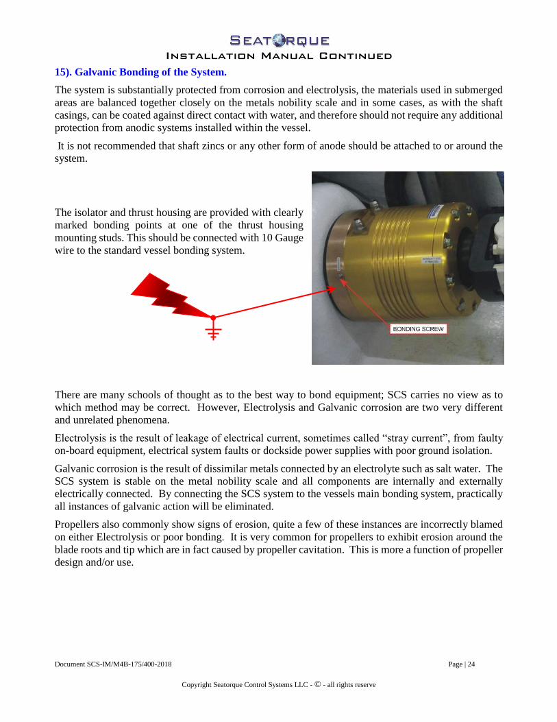
The isolator and thrust housing are provided with clearly
marked bonding points at one of the thrust housing
mounting studs. This should be connected with 10 Gauge
wire to the standard vessel bonding system.
There are many schools of thought as to the best way to bond equipment; SCS carries no view as to
which method may be correct. However, Electrolysis and Galvanic corrosion are two very different
and unrelated phenomena.
Electrolysis is the result of leakage of electrical current, sometimes called “stray current”, from faulty
on-board equipment, electrical system faults or dockside power supplies with poor ground isolation.
Galvanic corrosion is the result of dissimilar metals connected by an electrolyte such as salt water. The
SCS system is stable on the metal nobility scale and all components are internally and externally
electrically connected. By connecting the SCS system to the vessels main bonding system, practically
all instances of galvanic action will be eliminated.
Propellers also commonly show signs of erosion, quite a few of these instances are incorrectly blamed
on either Electrolysis or poor bonding. It is very common for propellers to exhibit erosion around the
blade roots and tip which are in fact caused by propeller cavitation. This is more a function of propeller
design and/or use.

Installation Manual Continued
Document SCS-IM/M4B-175/400-2018 Page | 25
Copyright Seatorque Control Systems LLC - © - all rights reserve
16). Painting of system.
It is important that the entire Seatorque system is protected from possible corrosion by direct contact
with salt water. It is imperative that the external shaft system is painted with two part under water
primer and at least two coats of high quality Anti-fouling paint.
Failure to paint and protect the shaft system will result in premature corrosion and possible failure.
For inboard components, it is particularly important that coupling seal areas are properly masked before
applying any paint for cosmetic or protective purposes. Paint in the seals will cause premature failure
of the oil seals voiding warranty coverage. The steel couplings are supplied pre-treated with protective
coatings which are designed to inhibit rust. Proper maintenance will further stop the couplings from
corroding, spray the inboard components of the system with WD40 or a similar water dispersal agent
for continued protection.
17). Post-Installation Notes
After installation is completed and the system has been filled with oil, the system requires a “break-in”
period to bed the seals. During this time some residual oil may appear to weep from the system. This
is normal; please allow at least 10 hours of operation for the break in process to complete.
After the system is installed, or after any service work, and to keep bilges clean, wash the housings
front and back with denatured alcohol to wash off any residual oil.
(Remember to keep caustic cleaning chemicals away from housings).
If any weeping or oil drips appear excessive or do not diminish after the initial break–in period:
1) Monitor the oil level site gauge on the SCS oil reservoir tank for fluid level change as well as a time
frame and measurement of the level change.
2) Place an oil absorber product at the location of any accumulated oil to help assess the severity of the
drip.
3) Contact your local Service Center or the SCS Factory Customer Service Department and give a clear
and comprehensive report detailing the problem.
Please remember that the more detail and information provided at this stage will assist SCS service
technicians in diagnosing the problem which will result in a faster determination of the service support
required. Wherever possible to help clarify the diagnosis please provide a photograph of the problem.
Please also note that an oil weep or drip does not denote that the system is in any danger of failure,
system problems will not occur as long as the oil level is visible in the oil reservoir sight tube between
the Minimum and Maximum level lines.
Normal operating temperatures should stabilize at 180ºF (82º C), be careful not to touch the thrust
housings after the vessel is stationary or when working around the thrust housings, severe burns could
be sustained.

Installation Manual Continued
Document SCS-IM/M4B-175/400-2018 Page | 26
Copyright Seatorque Control Systems LLC - © - all rights reserve
18). FINAL INSTALLATION OEM CHECK AND SIGN-OFF SHEET.
During/After Installation of your Seatorque Shaft System, please verify the following “Checkpoints” have been
completed and are in compliance with the SCS installation procedures outlined in this manual.
Please note: This Check Sheet is to aid the builder and its management team in establishing that all
components are installed correctly. It may be impossible during any third party inspection to verify many of
the items listed without dismantling the system once installed, and therefore could impact the validity of the
SCS warranty pre or post-delivery of the vessel.
Dated Checked Initials of Installer **
______________ ________ Verify the Shaft pocket face is clean, smooth, uniform in thickness and
Perpendicular to the shaft
______________ ________ Verify shafts marked “Port & Starboard” are installed Port & Starboard
______________ ________ Verify Thrust Housings are positioned with the Oil Ports facing UP
______________ ________ Verify All O-rings have been installed correctly:
1). ________ Thrust Housing to Isolator Bolting Flange
2). ________ Oil Impeller
3). ________ Coupling
______________ Verify no 5200 or equivalent sealant has been applied to the isolator
bushings and shaft pocket faces and any 5200 used is only around the
mounting studs in accordance with the installation manual.
______________ ________ Verify Isolators are sealed to shaft casing Thread with 3M-5200™ or
equivalent
______________ ________ Verify coupling bolt is set to correct torque rating per installation manual
______________ ________ Verify No Loctite™ was used on coupling bolt
______________ ________ Verify U-joint bolts are set to correct torque rating per installation manual
______________ ________Verify No Loctite™ was used on U-joint Bolts
______________ ________ Verify the U-joints are installed within the correct free slip dimension
______________ ________ Verify Co-planar alignment of transmission and shaft couplings
______________ ________ Verify U-joint driveline deflection is within specified parameters
______________ ________ Verify struts have been aligned & injected/packed as per installation manual
______________ ________ Verify Oil Reservoir Tanks are installed per the manual and verify
Length of hose run from the Thrust Housings.

Installation Manual Continued
Document SCS-IM/M4B-175/400-2018 Page | 27
Copyright Seatorque Control Systems LLC - © - all rights reserve
Date Checked Initials of Installer *
______________ ________ Verify the correct SCS supplied Oil Reservoir Hose type and fittings have
Been installed - No Substitutions
NO hose clamps or clips are used on supplied push-lock fittings
______________ ________ Verify the seals in the seal carriers have been properly and adequately
Greased.
______________ ________ Verify the seal carrier bolts have been correctly installed with Loctite™
______________ ________ Verify the system has been completely filled and purged with SCS Shaft Oil**
______________ ________ Verify propeller keys have been properly dressed and fitted
______________ ________ Verify propeller is not key bound and fitted to taper correctly
______________ ________ Verify propeller Nuts are correctly installed with locking tabs and bolts
______________ ________ Verify underwater gear has been painted per the manual
______________ ________ Verify the Nuts and Lock Washers on the Isolator mounting studs are
Installed with Marine Adhesive Sealant as per the manual
* Completion of this Post-Installation checklist is important to the validity of the SCS Limited Warranty.
This must be completed by the Builder/yard managers/Engineers and is not at any time to be viewed as the
responsibility of SCS Sales/Service personnel.
** All Seatorque shaft systems are shipped with the correct amount of oil plus 2 quarts. If after filling, more
than 2 quarts of oil remain, there may not be sufficient oil in the system. Should this occur, and before
operating the vessel, please contact a Seatorque service center or Seatorque Factory directly for advice and
assistance.
Installation Yard/Manufacturer Name: _____________________________________
Authorized Signature: _____________________________
Date: ______________________

Installation Manual Continued
Document SCS-IM/M4B-175/400-2018 Page | 28
Copyright Seatorque Control Systems LLC - © - all rights reserve
19). ADDENDUM
System Specifications, Information Charts and Additional Bulletins.

Marin
e p
ropulsio
n S
ystems
Shaft S
pecif
icatio
ns
SH
AF
T A
ND
CA
SIN
G S
PE
CIF
ICA
TIO
NS
Sh
aft
Mo
de
l1
00
17
52
00
22
52
50
27
53
00
35
04
00
45
05
00
Dia
me
ter
Inc
h1
.00
1.7
52
.00
2.2
52
.50
2.7
53
.00
3.5
04
.00
4.5
05
.00
mm
25
.40
44
.45
50
.80
57
.15
63
.50
69
.85
76
.20
88
.90
10
1.6
01
14
.30
12
7.0
0
Sh
aft
Mo
de
l1
00
17
52
00
22
52
50
27
53
00
35
04
00
45
05
00
Sh
aft
Ma
teri
al
AQ
22
™
AQ
22
HS
™
To
rsio
na
lP
SI
86
,60
07
0,0
00
Yie
ld(K
pa
)5
97
48
3
**
Sh
aft
Mo
de
l1
00
17
52
00
22
52
50
27
53
00
35
04
00
45
05
00
To
rqu
eF
t/L
bs
29
81
,29
21
,92
82
,74
63
,76
45
,01
16
,50
81
0,3
40
15
,44
62
1,9
80
30
,13
1
Ca
pa
cit
y(N
m)
40
51
,75
62
,62
03
,73
15
,11
56
,80
98
,84
31
4,0
50
20
,98
82
9,8
67
40
,94
3
Sh
aft
Mo
de
l1
00
17
52
00
22
52
50
27
53
00
35
04
00
45
05
00
Ca
sin
gIn
ch
1.6
62
.37
52
.87
53
.53
.54
44
.55
.55
.56
.5
OD
(mm
)4
2.1
66
0.3
37
3.0
38
8.9
08
8.9
01
01
.60
10
1.6
01
14
.30
13
9.7
01
39
.70
16
5.1
0
AN
SI
Pip
e S
ize
1 1
/42
2 1
/23
33
1/2
3 1
/24
55
6
Sh
aft
Mo
de
l1
00
17
52
00
22
52
50
27
53
00
35
04
00
45
05
00
Th
rus
t B
ea
rin
gL
bs
/F3
,88
06
,85
01
0,4
00
13
,70
01
3,7
00
21
,60
02
1,6
00
25
,90
02
3,7
00
33
,70
06
5,7
00
Ca
pa
cit
yN
17
30
03
0,5
43
46
,37
16
1,0
85
61
,08
59
6,3
09
96
,30
91
15
,48
21
05
,67
31
50
,26
02
92
,94
1
(Kg
/F)
1,7
32
3,0
58
4,6
43
6,1
16
6,1
16
9,6
43
9,6
43
11
,56
31
0,5
80
15
,04
52
9,3
30
** T
orq
ue
Ca
pa
cit
ies
ca
lcu
late
d a
t S
afe
ty F
ac
tor
of
5
Re
co
mm
en
de
d l
ub
ric
an
t -
Se
ato
rqu
e S
CS
75
W-9
0 -
Fu
ll S
yn
the
tic,
Extr
em
e P
ressu
re,
Sh
ock P
roo
f, E
xte
nd
ed
Ma
rin
e s
erv
ice
.
me
etin
g o
r e
xce
ed
ing
, A
PI
GL
-5,
Mil
PR
F-2
10
SE

Reco
mm
en
ded
To
rqu
e V
alu
es f
or
all
Faste
ners
Used
In
a S
eato
rqu
e S
yste
m
S
haft
Mo
del
10
01
75
20
02
25
25
02
75
30
03
50
40
04
50
50
0
Sh
aft
Co
up
lin
g B
olt
(Nm
)27
115
115
115
115
136
136
136
203
tba
tba
To
Sh
aft
Ft/Lbs
20
85
85
85
85
100
100
100
150 B
y a
pplic
ation
(Pre
torq
ue t
o 5
0%
) -
Lu
bri
cate
dB
olt
3/8
-24
5/8
-18
5/8
-18
5/8
-18
5/8
-18
3/4
-16
3/4
-16
1-1
41 1
/4-1
2
S
haft
Mo
del
10
01
75
20
02
25
25
02
75
30
03
50
40
04
50
50
0
M4 I
so
lato
r(N
m)
720
20
27
27
27
27
27
34
tba
tba
Stu
d N
uts
Ft/Lbs
515
15
20
20
20
20
20
25 B
y a
pplic
ation
Mo
un
tin
g B
ush
ing
s O
nly
(Tig
hte
n n
uts
se
qu
en
cia
lly in
clo
ck
pa
tte
rn a
t va
lue
sh
ow
n u
nti
l n
uts
tu
rn le
ss
th
an
on
e f
lat
- U
se
a c
alib
rate
d T
orq
ue
Wre
nc
h)
CA
RD
AN
SH
AF
TD
IN M
od
el
(Un
ivers
al
Jo
int)
2C
5C
7C
8.5
C1
0C
12
.5C
Bo
lt(G
rad
e)
(8)
(8)
(8)
(8)
(8)
(10.9
)
Dia
mete
rIn
ch
es
5/1
6-2
4 U
NF
3/8
-24 U
NF
1/2
-20 U
NF
1/2
-20 U
NF
5/8
-18 U
NF
M18-1
.5
Pre
-To
rqu
e S
ett
ing
2C
5C
7C
8.5
C1
0C
12
.5C
Lu
bri
cate
d(N
m)
19
54
88
88
136
203
Ft/Lbs
14
40
65
65
100
150
Fin
al
To
rqu
e S
ett
ing
2C
5C
7C
8.5
C1
0C
12
.5C
Lu
bri
cate
d(N
m)
27
68
115
115
203
271
Ft/Lbs
20
50
85
85
150
200
Tra
nsm
issio
n A
dap
ter
SA
EM
ET
RIC
Min
/Max
Stu
d S
ize
7/1
6"
5/8
"3/4
"1"
M10
M16
M18
M20
M22
M24
To
rqu
e(N
m)
Min
54
171
285
569
33
142
190
285
379
522
Sett
ing
sM
ax
79
244
407
813
47
203
271
407
542
745
Th
read
s D
ryF
t/Lbs M
in40
126
210
420
24
105
140
210
280
385
Max
58
180
300
600
35
150
200
300
400
550
PR
OP
EL
LE
R N
UT
TO
RQ
UE
Reco
mm
en
ded
Fo
r 1:1
6 R
ati
o S
AE
J755 S
haft
Tap
ers
- D
RY
TH
RE
AD
S
Sh
aft
Mo
del
10
01
75
20
02
25
25
02
75
30
03
50
40
04
50
50
0
(Nm
)7
318
436
573
637
799
982
1272
1745
2127
2728
Ft/Lbs
5235
322
423
470
590
725
939
1288
1570
2013
Copyright ©
2016 -
Seato
rque C
ontr
ol S
yste
ms -
All
Rig
hts
Reserv
ed

Torque to full value listed in the Torque Chart in this
manual on each nut in a "Clock Sequence"
Continue to tighten around the nuts in sequence until all
Nuts meet the Required Torque setting.
Required Torque is achieved when no nuts turn more than one flat
this is usually achieved after 6 to 10 times around the Clock.
Once Full Torque has been achieved
The wall of the Isolator Bushing will
Show a "Bulge" or curvature between
0.5mm to 1mm or 0.02" to 0.040"
when viewed from the side
(Depending on Shaft model)

Casing & Locking Ring Torque Chart
The following Settings are based on Torque preload plus angular displacement to achieve correct casing prevailing torque loads. Pre torque casing on all models to 50 Ft/Lbs (68 Nm) [7 Kg/M] Shaft Model Deg of Rotation Angular Displacement
175 8 0.1658” (4.21mm) 200 7 0.1833” (4.66mm)
225/250 7 0.2138” (5.43mm)
275/300 7 0.2443” (6.21mm)
350 7 0.2748” (7.00mm) 400 6 0.2913” (7.40mm)
Locking Ring Torque Shaft Model Thread Basic Major-TPI Clamp Force LbsF (KgF) Torque Ft/Lbs. (Nm) [kg/M]
175 2.375-14 5389 (2445) 160 (217) [22.12] 200 2.850-12 5614 (2547) 200 (271) [27.65] 225/250 3.4375-12 5818 (2640) 250 (339) [34.56] 275/300 3.9688-12 5543 (2515) 275 (373) [38] 350 4.4375-12 5408 (2454) 300 (407) [55.3] 400 5.4375-10 5150 (2336) 350 (475) [48.34]
Preloading the Shaft Casing Once the casing is threaded into place as far as possible to achieve a metal to metal hard stop, a pipe wrench should be placed on the casing, as close as possible to the isolator mount at the shaft pocket (M4B) or stern tube (ST4B) end Apply the preload torque manually as follows: Divide the torque figure listed above by the length of wrench handle from shaft axis to point on handle weight is applied in Feet or Meters i.e. For Wrench with 18” Handle (250Ft-Lbs/1.5Ft = 166.67 Lbs) Or (34.56Mkg/0.457M = 75.62Kg). Final torque the casing by making a register mark on the casing against the Isolator Mount, using the displacement figure from the chart above, measure from the register mark around the circumference of the casing and make a second destination mark on the face of the Isolator Mount Barrel, the casing must then be turned until the two marks are in alignment. (Note: casing threads are LH on Port and RH on Starboard casings). The casing preload and displacement provides a base locking force to the casing, the locking ring introduces a multiplier of three or more to the forces acting through both the casing and locking ring threads.

B-256 Hose Products DivisionParker Hannifin CorporationWickliffe, Ohiowww.parkerhose.com
+ Non-Standard
Fit
tin
gs
82 S
erie
s
B
82 Series FittingsUse with 801, 804, 821, 821FR, 831 and 836 hoses.
IF YOU HAVE QUESTIONS CONCERNING THE PRODUCTS OR APPLICATION OF THE PRODUCTSCONTAINED IN THIS CATALOG, PLEASE CALL:
PARKER HOSE PRODUCTS DIVISION - TECHNICAL SERVICES DEPARTMENTPHONE: 440-943-5700
FAX: 440-943-3129www.parkerhose.com
82 Series Assembly Instructions
Push-Lok 82 Series Assembly Instructions
1. Identify Over All Length (OAL) of hose assembly and the Cut OffAllowance (COA) length of fitting(s) by use of the fitting data table.
4. Insert fitting into hose until first barb is in the hose.
Push-Lok 82 Series Disassembly Instructions
2. Grip hose firmly and give it a sharp downward tug away fromthe fitting for disassembly.
1. Leave fitting in place, and cut hose approximately one inchlengthwise from the yellow plastic cap. IMPORTANT: Be carefulnot to nick barbs when cutting hose.
Caution: Insert the Push-Lok fitting all the way into the Push-Lok hose until the cut end is concealed by the yellow plastic cap.Caution: Sealing integrity may be damaged by use of exterior clamps.
OAL
OAL: Straight to Straight
2. Properly measure and mark hose. Cut hose squarely witha Parker Push-Lok cut-off tool or a sharp knife.
3. Lubricate the Push-Lok fitting, hose I.D., or both with light oil orsoapy water only - DO NOT USE HEAVY OIL OR GREASE.
5. Place end fitting against a flat object such as a work bench ofwall. Grip hose approximately one inch from end and pushwith a steady force until the end of the hose is covered by theyellow plastic cap.

Buletin SCS-CP0211
Bulletin SCS-CP0211 Suggested Cathodic Protection
This Bulletin to be used in conjunction with SCS suggested wiring diagram CP-0211-09. This suggested system is based on Passive Cathodic protection and as such should not be connected to DC negative on the vessels wiring system. Please note that this suggested approach is based on the Nobility scale found from the recognized Galvanic series of metals with reference levels set from a Silver-Silver Chloride electrode. Potential Voltage Material Millivolts [Mv] Stainless Steel 304/304L/316 0.00 – 10 (passive) Manganese Bronze 270 - 340 Nickle Aluminum Bronze (NyBrAl). [Propellers] 280 – 360 Measure the voltage in Millivolts between the Anode installed in the hull and the metals to be protected (Cathode) with the boat floating in Salt Water. Using the highest potential from the chart above add 200 to 250 Millivolts to the reading obtained. Adjust the size of the Zinc Anode until the reading equals the above result. This will depend on the location and area (size) of the metal to be protected. Do Not Exceed 1000 Mv, there could be risk of damage to the Anti-Fouling paint used on the hull of the boat. Derived from the Yacht and Boat Council of America (ABYC) guidelines.


3
Document Library
TS Data Sheet 06520, 05220
Rev: 2 Status: Active
Effective: 04/1/2006 Supersedes: 07/06/2000
3M™ Marine Adhesive/Sealant Fast Cure 5200
3M Part No.(s) 3M Part Descriptor(s)
06520 05220
10 cartridge (295 ml) – White 3 fl. oz. tube (90 ml) - White
Description A fast curing, one-part polyurethane that chemically reacts with moisture to deliver strong, flexible bonds with excellent adhesion to wood and fiberglass. Forms watertight, weather-resistant seals on joints and boat hardware above and below the waterline. In addition, its flexibility allows for dissipation of stress caused by shock, vibration, swelling or shrinking. Features
• Tough/flexible polyurethane polymer
• Non-shrinking
• One-part moisture cure
• Non-sagging formula
• Fast cure formula
Typical Physical Properties
Container 10 fl. oz. (295 ml) cartridge
3 fl. oz.(90 ml) tube
Base Polyurethane
Density lbs/Gallon (Appx.) 11.0 lbs/gallon
Color White
Solids Content (Appx.) 97%
Consistency Medium paste
Service Temperature - °F -40°F (-40°C) to 190°F (88°C)
Shore A Hardness (cured) 60
Specific Gravity 1.21
Coverage (10 oz.) 1/8 inch (0.3175 cm) bead = 120 lineal feet (36.6 m) Performance Properties
A 1/8 inch (0.3175 cm) dumbbell specimen with a 1/8 inch (0.3175 cm) square cross section was tested at 2.0 inches/minute (5.08 cm/minute).
Relative
Humidity
Temperature Tensile
Strength
psi (kg/cm2)
Elongation
(%)
50% 70°F (21°C) 1000 (70.3) 874

Cure:
Relative
Humidity
Temperature Time Cure Depth
Open Time 50% 70°F (21°C) 1 hour N/A
Open Time 90% 90°F (32°C) 15 min. N/A
Full Cure 50% 70°F (21°C) 24 hours 1/8 inch (0.3175
cm)
Cleanup:
For cleaning Fast Cure 5200 before it is cured, use a dry cloth to remove the majority of sealant, followed
by a cloth damp with General Purpose Adhesive Cleaner*, P. N. 08984, toluene or acetone. Cured Fast
Cure 5200 can be removed mechanically with a knife, razor blade or sanding.
Limitations - - Alcohol should not be used in preparation for bonding as it will stop the curing process. - Heat resistance - Maximum 190°F (88°C). Due to the decreased value in bond strength at elevated temperatures, we do not recommend use of this product above 190°F (88°C). - Do not apply at temperatures below 40°F (4°C) or on frost covered surfaces. - Fast Cure 5200 is not recommended for use as a teak deck seam sealer. Extended exposure to chemicals (teak cleaners, oxalic acid, gasoline, strong solvents and other harsh chemicals) may cause permanent softening of the sealant. - 3MTM Marine Adhesive/Sealant Fast Cure 5200 is not recommended for the installation of glass, polycarbonate or acrylic windows that are not also mechanically fastened with a system designed by the manufacturer. Inconsistent adhesion of these unprimed substrates, specific design of the window and movement due to thermal expansion and flexing, may cause application failure. - When using 3MTM Marine Adhesive/Sealant Fast Cure 5200 with metals it may be necessary to prime the surface to achieve adequate adhesion and durability of the bond. Scotch-WeldTM Structural Adhesive Primer EC-1945 B/A may be used for priming of most metals.
Applications
Typical bonding and sealing applications include:
- Fiberglass deck to fiberglass hull
- Wood to fiberglass
- Portholes
- Deck fittings
- Moldings
- Trunk joints
- Between struts and planking
- Stern joints and hull planking
Structural bonding and sealing of:
- Wood
- Fiberglass
- Gelcoat
- Primed metal

Note – This is not a product re-call. Bulletin TSB-2-01/11/2011
Product Update – 2012
Optional Temperature Sensor Kit The Above product update applies to SCS Shaft Systems From ST/M3-175 Through ST/M3-400 Models supplied after November 2011: This Product update applies to new equipment shipped with Optional Temperature Sensors after November 2011, no changes are required for units already in service prior to Nov 2011. Due to design dimensional limitations only the 275, 300 & 350 Systems could be fitted with an internal sensor mounting pocket. This new feature allows all systems produced after November 2011 to install the optional SCS Oil Temperature Sensor Kit. Sensor Block Attachment point.
Fig 1). Half Fill Sensor Port with Shaft Oil
Prior to installing Sensor
Fig 2).
Shown with Hi-Accuracy Analog Sensor
All 2012 Series thrust Housing Faceplates - Sensor Block Mounts to ¼-20 tapped hole as shown in Fig 1). Optional Sensor block is supplied with mounting hardware and choice of standard analog, Hi-accuracy Analog and Hi-Accuracy Digital temperature probes depending on monitor system and or Gauge panel. Prior systems already in service without temperature sensor ports can be updated, for further information please contact SCS factory direct or an authorized SCS distributer.

3
Document Library
TS Data Sheet 06520, 05220
Rev: 2 Status: Active
Effective: 04/1/2006 Supersedes: 07/06/2000
3M™ Marine Adhesive/Sealant Fast Cure 5200
3M Part No.(s) 3M Part Descriptor(s)
06520 05220
10 cartridge (295 ml) – White 3 fl. oz. tube (90 ml) - White
Description A fast curing, one-part polyurethane that chemically reacts with moisture to deliver strong, flexible bonds with excellent adhesion to wood and fiberglass. Forms watertight, weather-resistant seals on joints and boat hardware above and below the waterline. In addition, its flexibility allows for dissipation of stress caused by shock, vibration, swelling or shrinking. Features
• Tough/flexible polyurethane polymer
• Non-shrinking
• One-part moisture cure
• Non-sagging formula
• Fast cure formula
Typical Physical Properties
Container 10 fl. oz. (295 ml) cartridge
3 fl. oz.(90 ml) tube
Base Polyurethane
Density lbs/Gallon (Appx.) 11.0 lbs/gallon
Color White
Solids Content (Appx.) 97%
Consistency Medium paste
Service Temperature - °F -40°F (-40°C) to 190°F (88°C)
Shore A Hardness (cured) 60
Specific Gravity 1.21
Coverage (10 oz.) 1/8 inch (0.3175 cm) bead = 120 lineal feet (36.6 m) Performance Properties
A 1/8 inch (0.3175 cm) dumbbell specimen with a 1/8 inch (0.3175 cm) square cross section was tested at 2.0 inches/minute (5.08 cm/minute).
Relative
Humidity
Temperature Tensile
Strength
psi (kg/cm2)
Elongation
(%)
50% 70°F (21°C) 1000 (70.3) 874

Cure:
Relative
Humidity
Temperature Time Cure Depth
Open Time 50% 70°F (21°C) 1 hour N/A
Open Time 90% 90°F (32°C) 15 min. N/A
Full Cure 50% 70°F (21°C) 24 hours 1/8 inch (0.3175
cm)
Cleanup:
For cleaning Fast Cure 5200 before it is cured, use a dry cloth to remove the majority of sealant, followed
by a cloth damp with General Purpose Adhesive Cleaner*, P. N. 08984, toluene or acetone. Cured Fast
Cure 5200 can be removed mechanically with a knife, razor blade or sanding.
Limitations - - Alcohol should not be used in preparation for bonding as it will stop the curing process. - Heat resistance - Maximum 190°F (88°C). Due to the decreased value in bond strength at elevated temperatures, we do not recommend use of this product above 190°F (88°C). - Do not apply at temperatures below 40°F (4°C) or on frost covered surfaces. - Fast Cure 5200 is not recommended for use as a teak deck seam sealer. Extended exposure to chemicals (teak cleaners, oxalic acid, gasoline, strong solvents and other harsh chemicals) may cause permanent softening of the sealant. - 3MTM Marine Adhesive/Sealant Fast Cure 5200 is not recommended for the installation of glass, polycarbonate or acrylic windows that are not also mechanically fastened with a system designed by the manufacturer. Inconsistent adhesion of these unprimed substrates, specific design of the window and movement due to thermal expansion and flexing, may cause application failure. - When using 3MTM Marine Adhesive/Sealant Fast Cure 5200 with metals it may be necessary to prime the surface to achieve adequate adhesion and durability of the bond. Scotch-WeldTM Structural Adhesive Primer EC-1945 B/A may be used for priming of most metals.
Applications
Typical bonding and sealing applications include:
- Fiberglass deck to fiberglass hull
- Wood to fiberglass
- Portholes
- Deck fittings
- Moldings
- Trunk joints
- Between struts and planking
- Stern joints and hull planking
Structural bonding and sealing of:
- Wood
- Fiberglass
- Gelcoat
- Primed metal