Embed Size (px)
Citation preview

HES-FBLHES - FRONT TO BACK LOADED
3U
Sealed Four Heat excHanger VPx & cPcI-S 3u encloSure SerIeS
» A conventional card-cage format, front-to-back loaded 3U COTS chassis » Progressive, 3, 5, 7 & 9 slot versions for conduction-cooled 1” pitch modules » Forced-air heat exchanger sidewalls, top cover & rear panel » Expressly suited for dry air contaminant-free high wattage SWaP applications » Standard rugged or high airflow military PX2 rear fans » Overhead internal forced-air recirculation for reduced payload hot spots » Oversized output capacity military power supply options » Up to 300 watts payload power dissipation in 9 slot version
1”
5 7 93
CM COMPUTER MILITARY COTS TECHNOLOGIES
300WPAYLOAD POWER DISSIPATION
HES - FRONT TO BACK LOADED 3U ATR
Heat Exchanger Sidewalls 3U ATR - Contaminant-free Enclosuresuitable for high wattage VPX & cPCI-S applications with 0.8, 0.85 & 1” pitch 3U eurocards
Our 3U series of Four Heat Exchanger sealed conventional card-cage enclosures have been designed for compact aerospace and UAV applications that require state-of-the-art power dissipation technology. This family of size-scalable chassis are ideal for advanced SWaP military systems operating in hostile air environments.
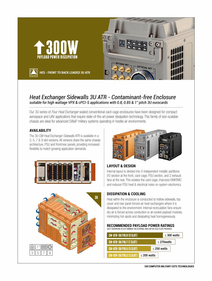
DiSSipATiON & COOLiNgHeat within the enclosure is conducted to hollow sidewalls, top cover and rear panel forced-air heat exchangers where it is dissipated to the environment. Internal recirculation fans ensure dry air is forced across conduction or air-cooled payload modules, minimizing hot-spots and dissipating heat homogeneously.
RECOmmENDED pAyLOAD pOwER RATiNgS(SELF DISSIPATING @ 55ºC AmbIENT: No ExTErNAL AIrFLow or CoLD PLATE ProvIDED)
CM-ATR-3U/FBL9 (9 SLOT)
CM-ATR-3U/FBL5 (5 SLOT)
≤ 300 watts
≤ 270watts
≤ 250 watts
CM-ATR-3U/FBL7 (7 SLOT)
3U
LAyOUT & DESigNInternal layout is divided into 4 independent metallic partitions: I/O section at the front, card-cage, PSU section, and 2 exhaust fans at the rear. This isolates the card-cage, improves EMI/EMC and reduces PSU heat & electrical noise on system electronics.
AvAiLABiLiTyThe 3U CM Heat Exchanger Sidewalls ATR is available in a 3, 5, 7 & 9 slot versions. All versions share the same chassis architecture, PSU and front/rear panels, providing increased flexibility to match growing application demands.
3 5 7 9
1”
CM-ATR-3U/FBL3 (3 SLOT) ≤ 200 watts
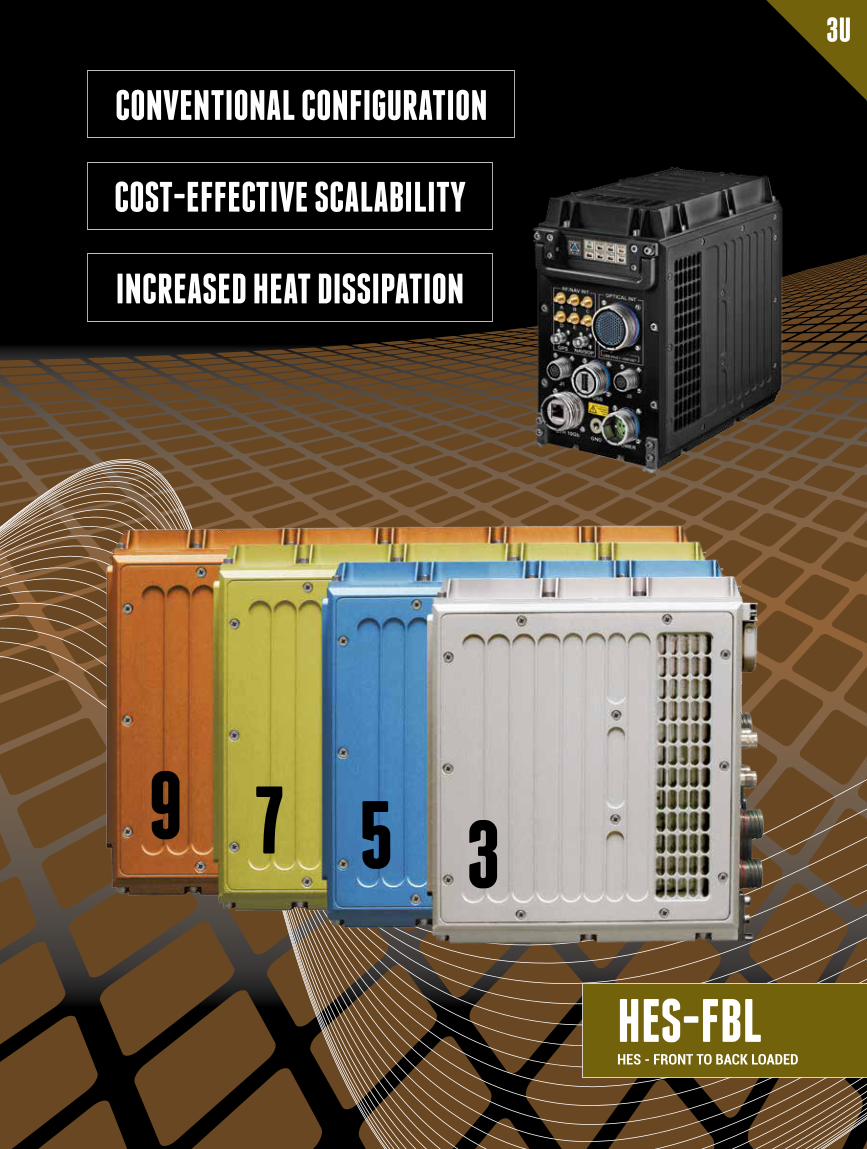
INCREASED HEAT DISSIPATION
COST-EFFECTIvE SCALABILITY
CONvENTIONAL CONFIgURATION
HES-FBLHES - FRONT TO BACK LOADED
3U
3579
CM COMPUTER MILITARY COTS TECHNOLOGIES
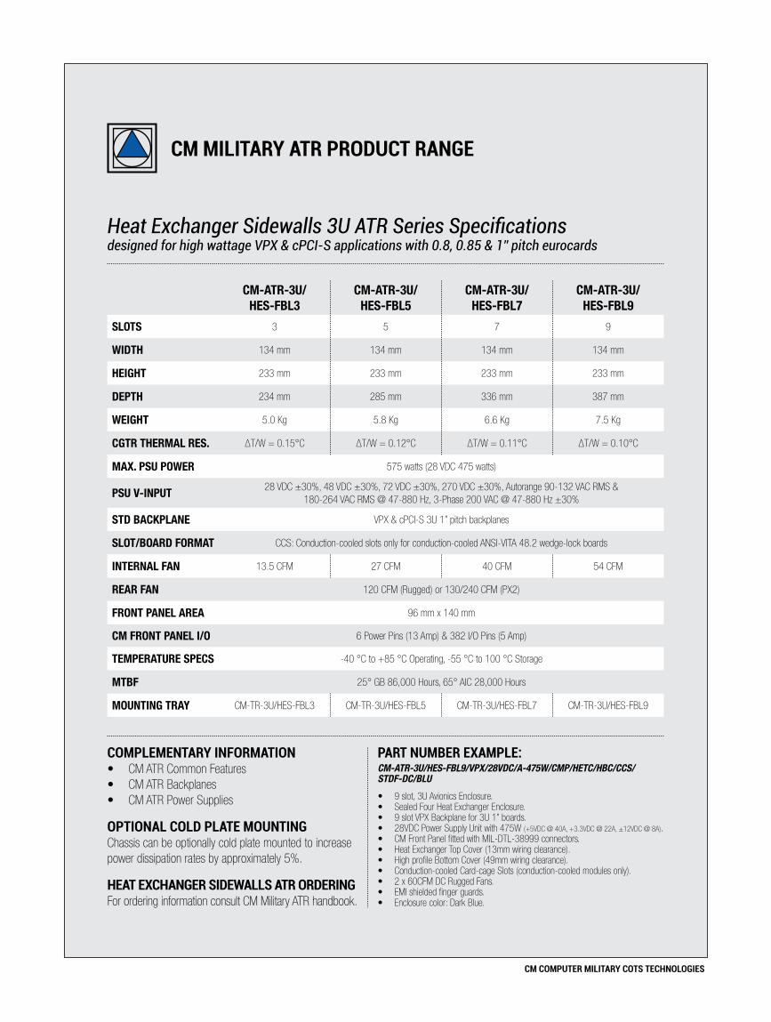
CM-ATR-3U/ HES-FBL3
CM-ATR-3U/ HES-FBL5
CM-ATR-3U/ HES-FBL7
CM-ATR-3U/ HES-FBL9
SLOTS 3 5 7 9
WIDTH 134 mm 134 mm 134 mm 134 mm
HEIGHT 233 mm 233 mm 233 mm 233 mm
DEPTH 234 mm 285 mm 336 mm 387 mm
WEIGHT 5.0 Kg 5.8 Kg 6.6 Kg 7.5 Kg
CGTR THERMAL RES. ΔT/W = 0.15°C ΔT/W = 0.12°C ΔT/W = 0.11°C ΔT/W = 0.10°C
MAX. PSU POWER 575 watts (28 VDC 475 watts)
PSU V-INPUT 28 VDC ±30%, 48 VDC ±30%, 72 VDC ±30%, 270 VDC ±30%, Autorange 90-132 VAC RMS & 180-264 VAC RMS @ 47-880 Hz, 3-Phase 200 VAC @ 47-880 Hz ±30%
STD BACKPLANE VPX & cPCI-S 3U 1” pitch backplanes
SLOT/BOARD FORMAT CCS: Conduction-cooled slots only for conduction-cooled ANSI-VITA 48.2 wedge-lock boards
INTERNAL FAN 13.5 CFM 27 CFM 40 CFM 54 CFM
REAR FAN 120 CFM (Rugged) or 130/240 CFM (PX2)
FRONT PANEL AREA 96 mm x 140 mm
CM FRONT PANEL I/O 6 Power Pins (13 Amp) & 382 I/O Pins (5 Amp)
TEMPERATURE SPECS -40 °C to +85 °C Operating, -55 °C to 100 °C Storage
MTBF 25° GB 86,000 Hours, 65° AIC 28,000 Hours
MOUNTING TRAY CM-TR-3U/HES-FBL3 CM-TR-3U/HES-FBL5 CM-TR-3U/HES-FBL7 CM-TR-3U/HES-FBL9
Heat Exchanger Sidewalls 3U ATR Series Specificationsdesigned for high wattage VPX & cPCI-S applications with 0.8, 0.85 & 1” pitch eurocards
coMPleMentary InForMatIon• CM ATR Common Features• CM ATR Backplanes• CM ATR Power Supplies
oPtIonal cold Plate MountIng Chassis can be optionally cold plate mounted to increase power dissipation rates by approximately 5%.
heat exchanger sIdewalls atr orderIngFor ordering information consult CM Military ATR handbook.
Part nuMBer exaMPle:CM-ATR-3U/HES-FBL9/VPX/28VDC/A-475W/CMP/HETC/HBC/CCS/ STDF-DC/BLU
• 9 slot, 3U Avionics Enclosure.• Sealed Four Heat Exchanger Enclosure.• 9 slot VPX Backplane for 3U 1” boards.• 28VDC Power Supply Unit with 475W (+5VDC @ 40A, +3.3VDC @ 22A, ±12VDC @ 8A).• CM Front Panel fitted with MIL-DTL-38999 connectors.• Heat Exchanger Top Cover (13mm wiring clearance).• High profile Bottom Cover (49mm wiring clearance).• Conduction-cooled Card-cage Slots (conduction-cooled modules only).• 2 x 60CFM DC Rugged Fans.• EMI shielded finger guards.• Enclosure color: Dark Blue.
cM MIlItary atr Product range

CM COMPUTER MILITARY COTS TECHNOLOGIES
/CT Enclosure Cooling TechniqueS: Standard Sealed 3U EnclosureSEF-18HP: Sealed with Extended Fins + 18 Heat Pipes 3U Enclosure HES: Sealed with Heat Exchangers 3U EnclosureHES-FBL(3-5-7-9): Sealed with Heat Exchangers 3U EnclosureHES-FBL(3-5-7-9)-HP: Sealed with Heat Exchangers + Heat Pipes 3U EnclosureFAC: Flowthrough Air Cooled 3U Enclosure (open, non-sealed)
/B Backplane TypeVME64x: Military VME64x Backplane (5 Slot 3U 1” Pitch)cPCI-S: Military Compact PCI Serial R.2.0 Backplane (3-5-7-9 Slot 3U 1” Pitch)VPX: VITA 46 Military VPX Backplane (3-5-7-9 Slot 3U 1” Pitch)VPX-6: VITA 46 Military VPX Backplane (6 Slot 3U 0.85” Pitch)
/I PSU Input Power Voltage28VDC: 28 VDC Input48VDC: 48 VDC Input72VDC: 72 VDC Input270VDC: 270 VDC Input90-264VAC: Autorange 90-264 VAC @ 47-880 Hz Input200VAC-3Ph: 200 VAC 3 Phase @ 47-880 Hz Input
/W Power Supply Unit WattsA-475W: 28 VDC (+5 VDC @ 40A, +3.3 VDC @ 22A, ±12 VDC @ 8A)
A-575W: All PSUs (+5 VDC @ 40A, +3.3 VDC @ 22A, ±12 VDC @ 12A)
A-675W: 28 VDC (+5 VDC @ 80A, +3.3 VDC @ 22A, ±12 VDC @ 8A)p
A-775W: All PSUs (+5 VDC @ 80A, +3.3 VDC @ 22A, ±12 VDC @ 12A)p
B-450W: 28 VDC (+5 VDC @ 20A, +3.3 VDC @ 45A, ±12 VDC @ 8A)
B-550W: All PS Us (+5 VDC @ 20A, +3.3 VDC @ 45A, ±12 VDC @ 12A)
B-564W: 28 VDC (+5 VDC @ 20A, +3.3 VDC @ 80A, ±12 VDC @ 8A)p
B-664W: All PSUs (+5 VDC @ 20A, +3.3 VDC @ 80A, ±12 VDC @ 12A)p
C-475W: 28 VDC (+5 VDC @ 20A, +3.3 VDC @ 22A, +12 VDC @ 16A,-12 VDC @ 8A)
C-575W: All PSUs (+5 VDC @ 20A, +3.3 VDC @ 22A, +12 VDC @ 21A, -12 VDC @ 12A)
C-775W: 28 VDC (+5 VDC @ 20A, +3.3 VDC @ 22A, +12 VDC @ 41A, -12 VDC @ 8A)p
C-825W: All PSUs (+5 VDC @ 20A, +3.3 VDC @ 22A, +12 VDC @ 41A, -12 VDC @ 12A)p
D-550W: 28 VDC (+5 VDC @ 40A, +3.3 VDC @ 45A, ±12 VDC @ 8A)p
D-650W: All PSUs (+5 VDC @ 40A, +3.3 VDC @ 45A, ±12 VDC @ 12A)p
E-550W: 28 VDC (+5 VDC @ 20A, +3.3 VDC @ 45A, +12 VDC @ 16A, -12 VDC @ 8A)p
E-650W: All PSUs (+5 VDC @ 20A, +3.3 VDC @ 45A, +12 VDC @ 21A, -12 VDC @ 12A)p
F-575W: 28 VDC (+5 VDC @ 40A, +3.3 VDC @ 22A, +12 VDC @ 16A,-12 VDC @ 8A)p
F-675W: All PSUs (+5 VDC @ 40A, +3.3 VDC @ 22A, +12 VDC @ 21A, -12 VDC @ 12A)p
All PSUs = All PSUs except 28 VDC input | 28 VDC = 28 VDC input onlypPSU not available for CM-ATR-3U/FAC & CM-ATR-3U/HES-FBL chassis models
/FP Front Panel LayoutCMP: Standard CM front panel fitted with MIL-DTL-38999 connectorsUDP: User-defined front panel layout (requires customer drawing)
/TC Chassis Top CoverSTC: Standard Top Cover. Wiring clearance 13mmFTC: Standard Top Cover. Wiring clearance 13mm. (Std. on SEF-18HP)
HTC: High profile Top Cover. Wiring clearance 35mmHETC: Heat Exchanger Top Cover. Wiring clearance 13mm (Std. on HES & HES-FBL)
/BC Chassis Bottom CoverSBC: Standard Bottom Cover. Wiring clearance below backplane 25mmHBC: High profile Bottom Cover. Wiring clearance below backplane 40mm
/CS Chassis Card-Cage SlotMCS: Mixed Card-cage Slots (mixed conduction-cooled & air-cooled boards)CCS: Conduction-cooled Card-cage Slots (conduction-cooled boards only) - MCS is not available for CM-ATR-3U/HES-FBL chassis models
/F Rear-Mounted Fan AssemblySTDF: 2x60 CFM DC Rugged fans (HES, HES-FBL & HES-FBL-HP) or
1x60 CFM DC Rugged fan (FAC)F115-400: 2x65 CFM 115 VAC @ 400Hz Rotron PX2 Military fans (HES-FBL,
HES & HES-FBL-HP) or 1x65 CFM Rotron PX2 Military fan (FAC)F200-400: 2x120 CFM 200 VAC 3PH @ 400Hz Rotron PX2 fans (HES-FBL,
HES & HES-FBL-HP) or 1x120 CFM Rotron PX2 Military fan (FAC)- No rear fan required for CM-ATR-3U/S & /SEF-HP, omit option from part number.- Rugged fans are fitted with aluminum housing. Operating range: -10ºC to +70ºC- Full military Rotron PX2 AC fans. Operating range: -54ºC to +125ºC
/C Chassis ColorB: Black, G: Navy Grey, E: Army Dark Earth, W: White, R: Red, PT: Platinum, YW: Yellow, GN: Green, BLU: Dark Blue, CR: Chromate MIL-C-5541 or O: Other
Part nuMBer exaMPle:CM-ATR-3U/SEF-18HP/VPX/28VDC/A-475W/UDP/FTC/SBC/CCS/E• 5 slot, Sealed with Extended Fins + 18 Heat Pipes 3U Avionics Enclosure.• 5 slot, 3U VPX 1” Pitch backplane. 28VDC input power supply. • A-475W power supply (+5 VDC @ 40A, +3.3 VDC @ 22A, ±12 VDC @ 8A).
• User-defined front panel layout (requires drawing).• Finned Top Cover (o13mm). Standard Bottom Cover (backplane o25mm).• Conduction-cooled Card-cage Slots (conduction-cooled boards only).• Enclosure color: Army Dark Earth.
3U Military ATR Chassis OrderingSWaP military aerospace enclosure part number configuration
Please carefully follow our chassis ordering guide for configuring your 3U ATR part number. Note that all CM 3U Backplanes integrate a functional Temperature Supervisory Unit (TSU) that controls Power Supply and Fan operation. Remote optoisolated control switches for ‘Battle-short’ and chassis PSU ‘on/standby’ are also fitted as standard.
cM atr orderIng InForMatIon
CHASSIS GEnERIC PART nUMBER:CM-ATR-3U /CT /B /I /W /FP /TC /BC /CS /F /C
MoUnTInG TRAy GEnERIC PART nUMBER:CM-TR-3U /CT
MANUFACTURED INTHEEU
US
MILITARYC
OM
PONENTS INSI
DE
CM COMPUTER MILITARY COTS TECHNOLOGIES
6U -
12 S
LOT FAC
SIXHEX-16HP
SIXHEX
HES
SEF-20HP
SEF
S
6U -
7 SLO
T
FAC
SIXHEX-20HP-1”
SIXHEX-16HP
SIXHEX-1”
SIXHEX
HES-1”
HES
SEF-18HP
SEF
S
6U -
5 SL
OT
FAC
SIXHEX-20HP-1”
SIXHEX-16HP
SIXHEX-1”
SIXHEX
HES-1”
HES
SEF-18HP
SEF
S
3U
FAC
HES
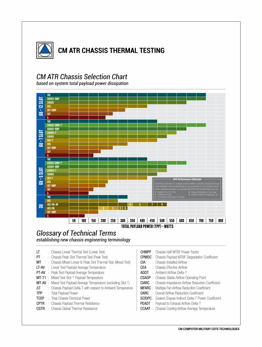
HES-FBL-HP 3 5 7 9
HES-FBL 3 5 7 9
SEF-18HP
S
50 100 150 200 250 300 350 400 450 500 550 600 650 700 750 800
TOTAL PAYLOAD POwEr (TPP) - wATTS
cM atr chassIs therMal testIng
CM ATR Chassis Selection Chartbased on system total payload power dissipation
LT : Chassis Linear Thermal Test (Linear Test) CHMPF : Chassis Half MTBF Power FactorPT : Chassis Peak Slot Thermal Test (Peak Test) CPMDC : Chassis Payload MTBF Degradation CoefficientMT : Chassis Mixed Linear & Peak Slot Thermal Test (Mixed Test) CIA : Chassis Installed AirflowLT-AV : Linear Test Payload Average Temperature CEA : Chassis Effective AirflowPT-AV : Peak Test Payload Average Temperature ADDT : Ambient Airflow Delta-TMT-T1 : Mixed Test Slot 1 Payload Temperature CSAOP : Chassis Stable Airflow Operating PointMT-AV : Mixed Test Payload Average Temperature (excluding Slot 1) CIARC : Chassis Impedance Airflow Reduction CoefficientΔT : Chassis Payload Delta-T with respect to Ambient Temperature MFARC : Multiple Fan Airflow Reduction CoefficientTPP : Total Payload Power OARC : Overall Airflow Reduction CoefficientTCEP : Total Chassis Electrical Power SCIDPC : Sealed Chassis Indirect Delta-T Power CoefficientCPTR : Chassis Payload Thermal Resistance PEADT : Payload to Exhaust Airflow Delta-TCGTR : Chassis Global Thermal Resistance CCAAT : Chassis Cooling Airflow Average Temperature
Glossary of Technical Termsestablishing new chassis engineering terminology
Performance estimates for compliance with the Military Operating Temperature Range. Power Dissipation rates are approximate and not guaranteed for any particular chassis. System operational variables can adversely affect ATR thermal performance such as:• Installed AC or DC PSUs• Selected Fan Pack• Air Density & Atmospheric Pressure
• Payload Distribution in Card-cage• Extreme Ambient Temperatures, etc.
ATR Performance Estimates