Embed Size (px)
Citation preview

www.aesseal.com
the AESSEAL® group of companies
designers and manufacturers of mechanical seals, bearing protectors and seal support systems which maximize rotating equipment up-time.
Seal Support Systems
Contents2
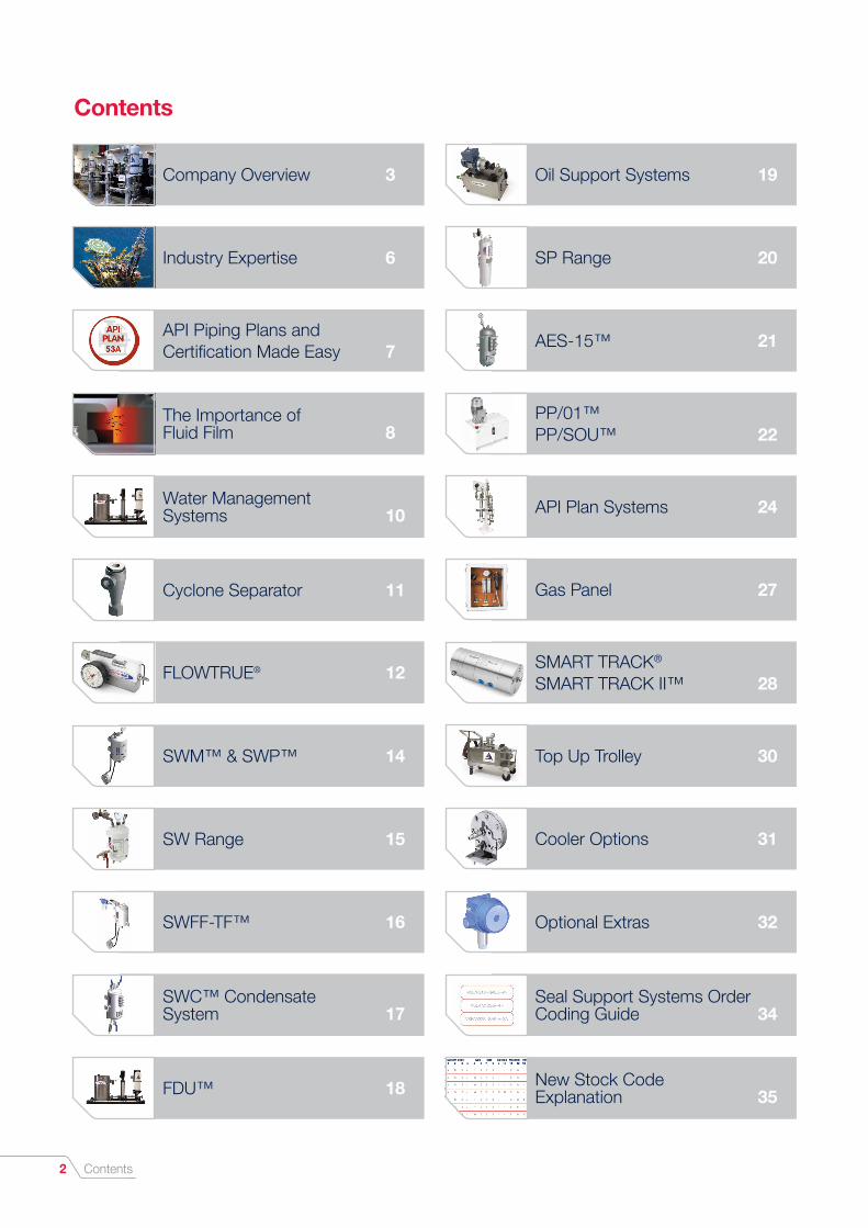
Contents
Company Overview 3 Oil Support Systems 19
Industry Expertise 6 SP Range 20
API Piping Plans and Certification Made Easy 7
AES-15™ 21
The Importance of Fluid Film 8
PP/01™ PP/SOU™ 22
Water Management Systems 10 API Plan Systems 24
SWM™ & SWP™ 14
SW Range 15
SWFF-TF™ 16 Optional Extras 32
SWC™ Condensate System 17
Seal Support Systems Order Coding Guide 34
FDU™ 18 New Stock Code Explanation 35
Cyclone Separator 11
FLOWTRUE® 12
Gas Panel 27
SMART TRACK®
SMART TRACK II™ 28
Top Up Trolley 30
Cooler Options 31

Company Overview
AESSEAL® is a leading global specialist in the design and manufacture of mechanical seals, bearing protectors and seal support systems.The company sets new standards in reliability, performance, service and cost. Service has been the key to the success of AESSEAL® and is at the core of the company purpose statement — ‘to give our customers such exceptional service that they need never consider alternative sources of supply.’ Through continuous investment, unique modular technology and an unparalleled dedication to customer service we aim to constantly exceed expectation.
Customer Focus
“We aim to deliver a customer experience that surpasses expectation and truly redefines what the world expects from their sealing specialist.”Simplicity. Our modular technology means a streamlined ordering process.
Customer-centric. Our people are encouraged to champion the customers’ cause.
Ethical and Responsible. AESSEAL® has been recognized as a Climate Change Champion and has won awards for corporate social responsibility and sustainability.
Partnership. We work with customers to deliver added value and long-term reliability solutions.
Investment. Over 7% of annual sales revenue has been reinvested in R&D over several decades. This has almost certainly led to the most advanced range of sealing technology available globally.
Engineered Excellence
AESSEAL® offers a wide range of innovative and modular seal support system’s to complement its mechanical seal designs.We have invested thousands of man hours reviewing the latest legislation and design codes delivering clarity and assurance.
We believe we are the only manufacturer to supply CE certified assemblies without the use of third-party sources. The AESSEAL® Global Technology Centre is certified to Module D, B1 and H1 — H1 being the highest level of Pressure Equipment Directive PED 2014/68/EU certification.
Of all the worlds water 97.4% is salt water, 2% is solid in ice caps and only 0.6% is suitable for
industrial use and human consumption.
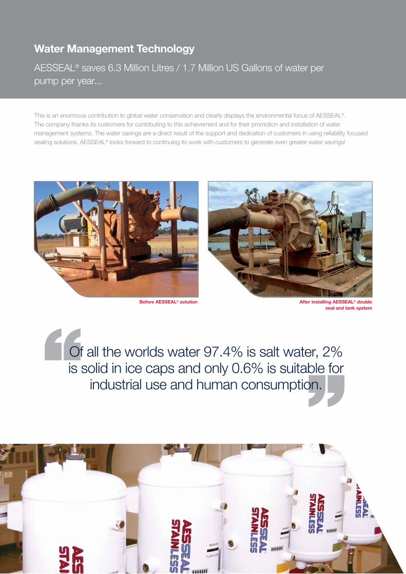
Before AESSEAL® solution After installing AESSEAL® double seal and tank system
Water Management Technology
AESSEAL® saves 6.3 Million Litres / 1.7 Million US Gallons of water per pump per year...
This is an enormous contribution to global water conservation and clearly displays the environmental focus of AESSEAL®. The company thanks its customers for contributing to this achievement and for their promotion and installation of water management systems. The water savings are a direct result of the support and dedication of customers in using reliability focused sealing solutions. AESSEAL® looks forward to continuing its work with customers to generate even greater water savings!

API 53B system designed in accordance with API 682
The Complex Made Simple 5
The Complex Made Simple
With its innovative approach to design, the AESSEAL® Complex Systems Division has introduced modularity and repeatability to what is, for some, an uncertain manufacturing process.
The Complex Systems Division’s team encompass design, fabrication, engineering and customer service to guarantee a seamless flow from inception through to specification and the delivery of truly beautiful quality products such as the Plan 53B system depicted.
CE certification for full assemblyWe believe that we are the only manufacturer to fully CE certify the entire assembly.
Global
Customer service is provided from 230 locations in 104 countries, including 9 manufacturing and 58 repair locations, with more than 300 customer service representatives who visit industrial plants every day.
The systems division at AESSEAL® supplies seal support systems to all global locations with the same focus on customer service.

Industry Expertise6
Oil & Gas
Power Generation
Chemical & Pharmaceutical
Bio / Ethanol
Mining & Minerals
Industry Expertise
The AESSEAL® modular seal support system range has evolved from application experience in industry’s most challenging environments. This means we have a proven, reliable system for you equipmentPlease contact your local AESSEAL® representative to discover more about proven seal support solutions.
Pulp & Paper
Food & Beverage
Water & Waste Water
Automotive
Metal Processing

API Piping Plans 7
European Legislation PED 2014/68/EUThe Pressure Equipment Directive was adopted on the 29th May 1997 and came into force on the 29th November 1999.
The Directive covers pressure equipment and assemblies with a maximum allowable pressure greater than 0.5 bar. Pressure equipment means vessels, piping, safety and pressure accessories. Assemblies mean several pieces of pressure equipment assembled to form an integrated, functional whole.
General requirements are as follows:
• They are safe
• The essential safety requirements covering design, manufacture and testing are met.
• They satisfy appropriate conformity assessment procedures
• They carry the CE mark
Equipment is classified either as SEP i.e. Sound Engineering Practice or classified in categories 1 to 4. The higher the category the greater the hazard and more demanding are the requirements. Products categorized under 2, 3 or 4 require third party notified body approval which are appointed by a member state.
The PED was transposed into UK law by the Pressure Equipment Regulations (PER). Failure to comply with the PER can result in the following:
• Such equipment cannot legally be placed on the market or put into service in the UK or the European Community or EEA
• Could result in prosecution and penalties on conviction of a fine, imprisonment or both
Notified body approval - All AESSEAL® pressure vessels and assemblies are examined and certified (EC design examination certificate see Figure 2) by a third party notified body.
The quality management system for manufacture is also examined and certified by a third party notified body.
ASME VIII Div.1 - The American Society of Mechanical Engineers is an internationally recognized organization. The International Boiler and Pressure Vessel Code states the rules of safety for governing the design, fabrication and inspection of boilers and pressure vessels during construction.
All AESSEAL® vessels are designed and manufactured to the latest standard which is updated every three years. All of the company’s welders are fully coded to EN 287-1 and ASME IX.
LSH
Figure 1
Certification
Figure 2
API Piping Plans and Certification Made Easy
API icons —To make the selection of a seal support system easier AESSEAL® has designed a number of API icons so that a customer is able to link products to specific API Piping Plans.The company has developed an API Piping Plan booklet as a guide. Examples of how the API Plans are displayed in this booklet are shown below:
API Piping Plan Booklet

The Importance of Fluid Film8
The Importance of Fluid Film
A single mechanical sealing device incorporates two flat faces, one fixed and one rotating, running against each other with a liquid film between them providing lubrication.This liquid film is commonly known as the fluid film. Without a stable fluid film between the faces they would be in full contact causing frictional heat build up and dry running, leading to excessive wear and component damage (Image 1). The key to successful sealing is the maintenance of a cool, clean and stable fluid film between the sealing faces (Image 2). This very thin, 2 - 3 micrometre, fluid film can be difficult to maintain and this is the primary challenge when sealing a pump application.
If a single mechanical seal is used then the process fluid becomes the fluid film. As long as the process fluid is an acceptable lubricant, is at an acceptable temperature and is not a dangerous substance, a single seal can be used.
Many process liquids are not, however, acceptable for cooling and lubricating the seal faces (Image 3). These fluids fall into the following categories:
• Slurries
• Hot liquids that can evaporate as the pressure drops across the faces
• Cold liquids that can become very viscous or solidify
• Liquids that crystallise as they contact atmospheric conditions
• Liquids that coke as they contact atmospheric conditions
• Liquids that leave a film or a deposit across the seal faces due to the heat generated between the faces
All of the above conditions require a double mechanical seal with an external barrier fluid between the two sets of seal faces. The external barrier fluid must be at a higher pressure than the sealing chamber pressure to drive the clean, cool barrier fluid across the inboard seal faces rather than allowing the process fluid to cross the faces (Image 4).
Reliability Enhancement
In April 2007 research was finalized on 11,000 mechanical seal failures recorded by all manufacturers worldwide over the previous two years. The results highlighted that inadequate seal support systems contributed to 22% of these failures. AESSEAL® technical support staff will recommend a reliable seal support system for your applications and remove this 22% failure risk.
Source: Stephen Flood, Performance Plus Ltd - “Mechanical Seal Reliability - What Realistically can Be Achieved?” presented at The
Mechanical Sealing Technology Seminar, I Mech E, London, April 07
4. Double mechanical seal with cool / clean barrier fluid
seal support system - 22%
Operations - 37%
Bearing - 13%
Workshop - 07%
Install / Align - 05%
Process - 12%
Seal - 04%
1. Dry running seal
2. Fluid film cooling the seal faces
3. Slurry at the seal faces
Barrier Fluid Choice 9
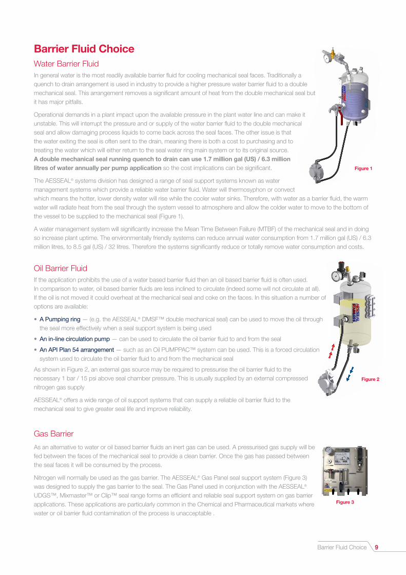
Barrier Fluid ChoiceWater Barrier FluidIn general water is the most readily available barrier fluid for cooling mechanical seal faces. Traditionally a quench to drain arrangement is used in industry to provide a higher pressure water barrier fluid to a double mechanical seal. This arrangement removes a significant amount of heat from the double mechanical seal but it has major pitfalls.
Operational demands in a plant impact upon the available pressure in the plant water line and can make it unstable. This will interrupt the pressure and or supply of the water barrier fluid to the double mechanical seal and allow damaging process liquids to come back across the seal faces. The other issue is that the water exiting the seal is often sent to the drain, meaning there is both a cost to purchasing and to treating the water which will either return to the seal water ring main system or to its original source. A double mechanical seal running quench to drain can use 1.7 million gal (US) / 6.3 million litres of water annually per pump application so the cost implications can be significant.
The AESSEAL® systems division has designed a range of seal support systems known as water management systems which provide a reliable water barrier fluid. Water will thermosyphon or convect which means the hotter, lower density water will rise while the cooler water sinks. Therefore, with water as a barrier fluid, the warm water will radiate heat from the seal through the system vessel to atmosphere and allow the colder water to move to the bottom of the vessel to be supplied to the mechanical seal (Figure 1).
A water management system will significantly increase the Mean Time Between Failure (MTBF) of the mechanical seal and in doing so increase plant uptime. The environmentally friendly systems can reduce annual water consumption from 1.7 million gal (US) / 6.3 million litres, to 8.5 gal (US) / 32 litres. Therefore the systems significantly reduce or totally remove water consumption and costs.
Oil Barrier FluidIf the application prohibits the use of a water based barrier fluid then an oil based barrier fluid is often used. In comparison to water, oil based barrier fluids are less inclined to circulate (indeed some will not circulate at all). If the oil is not moved it could overheat at the mechanical seal and coke on the faces. In this situation a number of options are available:
• A Pumping ring — (e.g. the AESSEAL® DMSF™ double mechanical seal) can be used to move the oil through the seal more effectively when a seal support system is being used
• An in-line circulation pump — can be used to circulate the oil barrier fluid to and from the seal
• An API Plan 54 arrangement — such as an Oil PUMPPAC™ system can be used. This is a forced circulation system used to circulate the oil barrier fluid to and from the mechanical seal
As shown in Figure 2, an external gas source may be required to pressurise the oil barrier fluid to the necessary 1 bar / 15 psi above seal chamber pressure. This is usually supplied by an external compressed nitrogen gas supply
AESSEAL® offers a wide range of oil support systems that can supply a reliable oil barrier fluid to the mechanical seal to give greater seal life and improve reliability.
Gas Barrier
As an alternative to water or oil based barrier fluids an inert gas can be used. A pressurised gas supply will be fed between the faces of the mechanical seal to provide a clean barrier. Once the gas has passed between the seal faces it will be consumed by the process.
Nitrogen will normally be used as the gas barrier. The AESSEAL® Gas Panel seal support system (Figure 3) was designed to supply the gas barrier to the seal. The Gas Panel used in conjunction with the AESSEAL® UDGS™, Mixmaster™ or Clip™ seal range forms an efficient and reliable seal support system on gas barrier applications. These applications are particularly common in the Chemical and Pharmaceutical markets where water or oil barrier fluid contamination of the process is unacceptable .
Figure 1
Figure 2
Figure 3

Water Management Systems
The AESSEAL® water management system range connects to the plant water line to feed the mechanical seal with a clean, cool and stable water barrier fluid.Water management systems are self replenishing and pressurising, being able to regulate down the pressure available in the plant water line. This is a reliable and cost saving seal support system method for a number of reasons:
Increase Plant Uptime & Mean Time Between Failure (MTBF) The Water Management system range reduces equipment downtime by increasing the MTBF of the mechanical seal.
Reduce Water Usage and Costs Traditional quench to drain and flush seal support methods waste huge quantities of water (up to 1.7 million gal (US) / 6.3 million litres of water per seal application per year). Water management systems reduce this water consumption to as little as 8.45 gal (US) / 32 litres per seal application per year. This is a massive saving that will reduce water purchase and effluent treatment costs.
Fast Return on Investment (ROI) The reduction in down time and water / energy / operator costs means that there is a typical ROI when installing an AESSEAL® Water Management system and mechanical seal of approximately 6-9 months.
Environmentally Friendly The reduction in the use of water and energy means that water management systems will make the customer’s manufacturing process more environmentally friendly and reduce your carbon footprint.
Reduce Operator Costs Water management systems are largely maintenance free and free up operator / maintenance resources for other areas of the plant.
Reduce Energy Usage and Costs Water Management systems restrict the amount of water migrating across the seal faces into processes that require evaporation during the manufacturing process.
AESSEAL® water management systems save in excess of 25 billion US gallons / 95 billion litres of water for customers each year.
CYCL™
FLOWTRUE®
SWM™ & SWP™
SWFF-TF™
SW Range
SWC™
FDU™
Water Technology LadderThe water technology ladder shows the progression of technology within the company’s water management system range.
Water Management Systems10

Water Management Systems 11
Cyclone Separator
The CYCL™ (Cyclone Separator) is designed to separate heavy particles from the product liquid. The clean fluid can be used as flush liquid, improving conditions at the seal faces. The separated particles drain back into the sealed product. The benefit is a reliable and low cost sealing system for heavy product particle applications which does not require an independent flush supply.
AESSEAL® CYCL™ Cyclone Separator
Item Description
1
2
3
Cyclone separator body
Hex. reducing bush
Dowty washer
B F
G
AH
CD
E
3
2
1
CB
D
A
E
Mechanical seal
Dirty product liquid pressure feed
Cyclone separator
Clean product liquid(Mechanical seal flush fluid)
Dirty product liquid return to pump suction
Item Description
A
B
C
D
E
Style Ø A, B. C Ø D Ø E Ø F Ø G Ø H
316 SS
316 SS
Duplex
Duplex1” NPT
1/2” NPT46mm1.89”
66mm2.60”
35mm1.38”
118mm4.65”
35mm1.38”
82mm3.20”
106.5mm4.09”
57mm2.20”
220mm8.7”
57mm2.20”
CYCL™ - Items and Sizing CYCL™ Parts List
CYCL™ Key interface dimensions, mm (inches)
CYCL™ - Operation

Water Management Systems12
Label
A
B
C
D
E
F
G
H
Description
Cartridge assembly
Pressure gauge
Flow channel
Valve adjustment key
Flow control valve
Water connections
Pressure control value
Polyacetal standardwhite body material
Purpose
The heart of the system, also contains the cleaning function
Indicates the pressure of the water at themechanical seal (double seal models only)
Gives details of the flow of waterthrough the FLOWTRUE®
Used to adjust the flow and presssure control valves
Controls the volume of water flowing through the FLOWTRUE®
Connects the FLOWTRUE® to themechanical seal and water feed
Controls the pressure of the water at the seal(double seal models only)
Maximum temperature 80°C / 176°F,maximum pressure 25 bar / 360 psi
Features Benefits
Flow cartridge design
Unique segmental valves
Innovative flow tube cleaningmechanism
Integrated non-return valve
Modular design
Flow and pressure controls can onlybe adjusted by using an allen key
Cartridge has a tapered design which gives largerclearances. This means that it is less likely to clog thancompetitor modelsThere are larger clearances within the FLOWTRUE®
flowcontrol valve. This means that it is less likely to clog thancompetitor models
FLOWTRUE® can be cleaned without interrupting flow or
pressure
Protects the plant water supply from product contamination
Ensures that the FLOWTRUE® can be easily upgraded
and repaired
Restricts the opportunity for accidental adjustmentof flow or pressure by operators
FLOWTRUE ® Product Range
FT - FLOWTRUE® for packing and single seals (push on connections).
FTP - FLOWTRUE® with pressure gauge for packing and single seals (push on connections).
FTPB - FLOWTRUE® with pressure gauge and back pressure control valve for double mechanical seals (push on connections).
FT-SC - FLOWTRUE® for packing and single seals (screwed connections).
FTP-SC - FLOWTRUE® with pressure gauge for packing and single seals (screwed connections).
FTPB-SC - FLOWTRUE® with pressure gauge and back pressure control valve for double mechanical seals (screwed connections).
A B C D
E
F
G
H
FLOWTRUE®
The AESSEAL® FLOWTRUE® is a robust and adjustable flow meter that controls the amount of water flowing to the mechanical seal for cooling purposes. The unique and advanced FLOWTRUE® design means that of all the flow meters available it is the least likely to clog. This is due to large internal clearances within the design. There are three models of the FLOWTRUE® available, which enable the product to be used on packing applications, single seals and double mechanical seals.

Water Management Systems 13
FLOWTRUE® Selection Guide
Below are five steps to follow in order to select a FLOWTRUE®.Optional extras are ordered as separate items.
FLOWTRUE® Base Model
For use with packed glands and singleseals without pressure gauge
For use with packed glands and singleseals with pressure gauge
For use with double mechanical seals, withpressure gauge, with back pressure valve FTPB-XX-YYY
FTP-XX-YYY
FT-XX
(Code)
Flow Range (XX)
0.1 - 0.4 gpm (0.5 - 1.5 l/min)
0.2 - 0.8 gpm (0.5 - 3.0 l/min)
0.25 - 2.0 gpm (1.0 - 8.0 l/min)
1.0 - 4.0 gpm (2.0 - 15 l/min)
04
08
20
40
No gauge
0 - 145 psi (0 - 10 bar)
0 - 360 psi (0 - 25 bar)
Pressure Gauge Range (YYY)
145
360
Polyacetal (standard)
Max Pressure
25 Bar (360 psi)
10 Bar (145 psi)Polyethylene
80ºC (176ºF)
60ºC (140ºF)
Coding
PE
Material Max Temperature
Screwed connections 1/4” NPT SC
CodingConnection
10mm Push-on (standard)
STEP 1 - Selection of base model
STEP 2 - Selection of flow range
STEP 3 - Selection of pressure range
STEP 4 - Selection of main body material
STEP 5 - Selection of connections
Hose kit for screwed connection models
1 o� 3/8” (10mm) ID Hose x 5ft (1.5m) & SS seal fittings - FT & FTB model
2 o� 3/8” (10mm) ID Hose x 5ft (1.5m) & SS seal fittings - FTPB model
2 o� 12mm OD Hose x 5ft (1.5m) & 4 SS compression fittings & 2 SS seal fittings
1 o� 12mm OD Hose x 5ft (1.5m) & 2 SS compression fittings & 1 SS fitting
2 o� 1/2” OD Hose x 5ft (1.5m) & 4 SS compression fittings & 2 SS seal fittings
1 o� 1/2” OD Hose x 5ft (1.5m) & 2 SS compression fittings & 1 SS seal fitting
Stock Code Description
FLOWTRUE® mounting options
Mounting bracket for push on connection models, Stainless Steel
Mounting bracket for screwed connection models, Stainless Steel
Floor mount stand, 316 Stainless Steel
FT-BRKT
FT-BRKT-SC
FT-STAND
Inductive Alarm
FT-ALARM-AC250 AC 20-250 volts
FT-ALARM-DC55 DC 10-55 volts
FT-HSK-FT
FT-HSK-FTPB
FT-HSK-FT-04
FT-HSK-FTPB-04
FT-HSK-FT-12
FT-HSK-FTPB-12
Hose kit for push-on connection models
Optional Extras
Order Example - FLOWTRUE® with back pressure valve, with pressure gauge for double seals, 0.2-0.8 gpm, 0-360 psi, Polyacetal body, Threaded connections = FTPB - 08 - 360 - SC.
Order Example - FLOWTRUE® without pressure gauge, for single seals, 0.1-0.4 gpm Polyethylene body, Push-on connections = FT - 04 - PE.

Water Management Systems14
Label
A
Description
Check valve
PurposeProtects against process entering the plant water line and protects the barrier fluid pressure against fluctuations in plantwater line pressure
DVessel - (304 SS construction, 10 litre / 2.64 gal (US) capacity (SWM™), 12 litre / 3 gal (US) weld pad type (SWP™), 80˚C / 176˚F temperature limit)
Dissipates the heat from the barrier fluid to atmosphere
C Weld pad level gauge(SWP™ only)
Visual indication of barrier fluid level in the vessel
B Pressure gauge Displays the barrier fluid pressurein the system
E Drain valve Drain barrier fluid from the system
F Mechanical seal feed andsystem return lines
Supplies barrier fluid to the mechanical seal and back to the system
G Mechanical seal Not supplied as part of the SWM™ or SWP™ systems
H Mounting brackets Securely mounts the SWM™ or SWP™ systems
*Protection against freezing required for water below 0 CO
Features Benefits
304 SS vessel construction
Non-return valve
Weld pad level gauge (SWPTM only)
Suitable for a range of challenging environments
Robust and industrially acceptable visual indication of barrier fluid level
Protects plant water supply from potential contamination and maintains vessel pressure in the event of supply interruption
Water from the plant water line enters the system.
Barrier fluid pressure will be the maximum pressure available from the plant water line.
The barrier fluid is circulated to the seal and back to the system by the thermosyphon effect.
1.
2.
3.
Operating Principle
2
3
1
B
A
H
E
D
F
G
SWM™ System
SWM™ & SWP™
The SWM™ (System Water Management) & SWP™ (System Weld Pad) are closed loop water management systems.These systems operate at the maximum pressure available in the plant water line (i.e. if the plant water line pressure is 45 psi / 3 bar the pressure of the barrier fluid in the tank will be the same). A check valve is supplied as part of the system, which ensures that the plant water line does not become contaminated with process and also ensures that the barrier fluid pressure remains at the maximum available from the plant water line even if the water line pressure fluctuates (e.g. if a plant operator uses a hose and reduces the plant water line pressure, the barrier fluid pressure in the SWM™ or SWP™ is not effected). Barrier fluid is circulated from the system to the seal and back to the system via the thermosyphon effect (see operating principle below). The SWP™ system incorporates a robust weld pad level gauge (SWP™ only) which allows an industrially acceptable visual indication of barrier fluid level.
Maximum Set Pressure: 6 barg / 87 psig Maximum Design Pressure: 10 barg / 145 psig Maximum Temperature: 80°C / 176°F (with suitably rated piping / hosing) Minimum Temperature: 0°C / 32°F
B
H
A
C
E
D
F
G
SWP™ System

Water Management Systems 15
SW Range
The SW Range consists of the SW2™ and SW3™ water management systems.The environmentally friendly SW Range systems connect directly to the plant water line. Using the pressure regulator supplied, the plant water line pressure can be adjusted so that the systems barrier fluid pressure is set at 1 bar / 15 psi above stuffing box pressure. The flow indicator allows a visual indication of mechanical seal upset or failure. The SW3™ is supplied with finned tubing as standard so that it can be used on high heat applications. Barrier fluid is circulated to and from the mechanical seal via the thermosyphon effect.
Maximum Set Pressure: 6 barg / 87 psig Maximum Design Pressure: 10 barg / 145 psig Maximum Temperature: 80°C / 176°F (with suitably rated piping / hosing) Minimum Temperature: 0°C / 32°F
Features Benefits
304 SS vessel construction
Water regulator
Flow indicator
Non-return valve
Supplied as a complete system
Suitable for a range of challenging environments
Maintains vessel water level and pressure
Visually alerts the user of an inboard seal failure
Protects plant water supply from potential contamination and maintains vessel pressure in the event of water supply interruption
The SW Range have all the components necessary for fast and easy installation
Label
B
Description
Non-return valve (Brass)
Purpose
Protects plant water supply from potential contamination from the process.Protects the barrier fluid from pressure flucuations in the plant water line
D Flow indicator (SS) Provides a visual indication of a mechanical seal upset(White ball will become visable)
A Pressure gauge (Brass) Displays the pressure of the barrier fluid in the SW2TM system
CPressure regulator(Brass, Max outlet pressure10 bar / 150 psi)
Regulates the plant water line pressure so it can be set at 1 bar / 15psi above stu�ng box pressure Automatically replenishes lost water and re-sets barrier fluid pressure if there is a mechanical seal upset
E
Vessel- (304 SS Construction 10 litre / 2.64 gal (US)capacity, 25 litre / 6.60gal (US) option, 80˚C / 176˚F temperature limit)
Dissipates the heat from the barrier fluid to atmosphere
F Drain valve (Nickelplated Brass)
When this is opened it cleans out any sediment at the bottom of the vessel. When it is closed again the pressure regulatorwill replenish any water lost and bring the SW2TM back up topressure
G Mechanical seal feed andreturn lines Supplies barrier fluid to and from the mechanical seal
H 3-way valve (SW2TM
only Brass)Enables the flushing of the seal for cleaning purposes.Is also the point where barrier fluid returns to the System
I Mounting brackets Securely mounts the SW Range
Water from the plant water line enters the system.
The pressure of the barrier fluid in the vessel can be regulated via the pressure regulator
The barrier fluid is circulated to the seal and back to the system by the thermosyphon effect.
1.
2.
3.
1
2
3
Operating Principle
SW2™ Water Management System
SW3™ Water Management System
I
B D
C
A
E
F
HG

Water Management Systems16
In-line filter (1 micron) Cleans plant water before it fills the vessel
Heart of the SWFF-TF™ systemFlow Fuse™ (Nickel plated Brass construction)
Vessel - (304 SS construction10 litre / 2.64 gal (US) capacity,25 litre / 6.60 gal (US) option16 bar / 232 psi pressure limit80°C / 176°F temperature limit)
Thermal Fuse™ (Brass)
Drain valve (Nickel plated Brass)
Seal feed and return lines
Mounting brackets
Pressure regulator
Activation indicator and manual reset button
Automatic reset adjusting screw
Flow Fuse™ vessel inlet
Integral check valve
Plant water inlet Is the point where the plant water line is connected to the Flow Fuse™
Protects the plant water supply from potentialcontamination from the process
Is the point where the Flow Fuse™ connects to the system vessel
When screw is fully screwed in the Flow Fuse™ will be in manual reset mode. When it is screwed out it will be in auto reset mode
When the red button moves outside the Flow Fuse™casing it shows that it has been activated. The button needs to be pushed in to refill the vessel in manual reset mode
Regulates the plant water line pressure to 2 bar / 30 psi above seal chamber pressure
Provides a secure and stable mounting forthe SWFF-TF™ system
Carries barrier fluid to and from the mechanical seal
Drains any sediment from the SWFF-TF™
Will relieve the system of excess pressurebuild up as a result of a temperature increase
Dissipates the heat from the barrier fluidto atmosphere
Label Description Purpose
A
B
C
D
E
F
G
H
I
J
K
L
M
Features Benefits
Flow sensing shut o� valve
Water regulator
Automatic reset facility
Thermal relief valve Maintains systems pre-set pressure by accommodatingany thermal expansion
Protects the mechanical seal from running dry duringprocess up-sets
Protects the process from barrier fluid contamination uponcatastrophic seal failure
Maintains water level and pressure, which reduces due tonormal seal operation
SWFF-TF™
The intelligent SWFF-TF™ system incorporates the Flow Fuse™ and Thermal Fuse™ products: The Flow Fuse™ is designed to restrict barrier fluid contamination of the process upon momentary or permanent seal failure. The Flow Fuse™ does this by isolating the seal support system from the plant water supply when it detects an abnormally high flow of water. The Flow Fuse™ product has two operating functions. These are manual-reset and auto-reset. In manual-reset the Flow Fuse™ will completely isolate the plant water supply upon the detection of seal failure and the only way to reset the Flow Fuse™ is manually. This mode is most suited to applications where barrier fluid contamination of the process cannot be tolerated. In auto-reset mode, upon seal failure the Flow Fuse™ will shut off the plant water supply but allow a small volume of water to continue to pass through. If the seal failure is momentary (e.g. temporary parting of the seal faces) the Flow Fuse™ will automatically reset itself to the original operating pressures once the seal failure has been resolved. The Thermal Fuse™ is a pressure relief valve designed to relieve the system of pressure build up as a result of a temperature increase.
Maximum Set Pressure: 6 barg / 87 psig Maximum Design Pressure: 10 barg / 145 psig Maximum Temperature: 80°C / 176°F (with suitably rated piping / hosing) Minimum Temperature: 0°C / 32°F
A
B
C
D
E
GF
I
J
KL
M
H
Water Management Systems 17
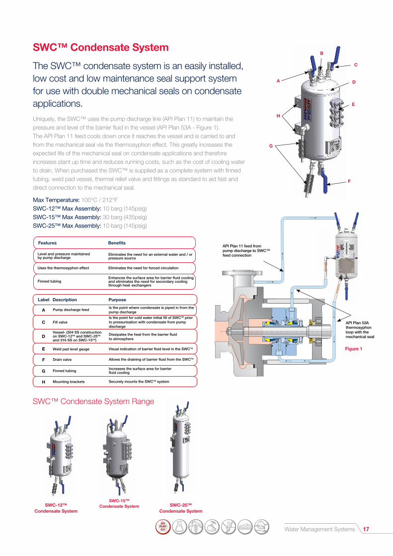
SWC™ Condensate System
The SWC™ condensate system is an easily installed, low cost and low maintenance seal support system for use with double mechanical seals on condensate applications.Uniquely, the SWC™ uses the pump discharge line (API Plan 11) to maintain the pressure and level of the barrier fluid in the vessel (API Plan 53A - Figure 1). The API Plan 11 feed cools down once it reaches the vessel and is carried to and from the mechanical seal via the thermosyphon effect. This greatly increases the expected life of the mechanical seal on condensate applications and therefore increases plant up time and reduces running costs, such as the cost of cooling water to drain. When purchased the SWC™ is supplied as a complete system with finned tubing, weld pad vessel, thermal relief valve and fittings as standard to aid fast and direct connection to the mechanical seal.
Max Temperature: 100°C / 212°F SWC-12™ Max Assembly: 10 barg (145psig) SWC-15™ Max Assembly: 30 barg (435psig) SWC-25™ Max Assembly: 10 barg (145psig)
Features Benefits
Level and pressure maintainedby pump discharge
Uses the thermosyphon eect
Finned tubing
Eliminates the need for an external water and / orpressure source
Eliminates the need for forced circulation
Enhances the surface area for barrier fluid cooling and eliminates the need for secondary cooling through heat exchangers
C Fill valveIs the point for cold water initial fill of SWCTM prior to pressurisation with condensate from pump discharge
DVessel- (304 SS construction on SWC-12TM and SWC-25TM
and 316 SS on SWC-15TM)
Dissipates the heat from the barrier fluid to atmosphere
E Weld pad level gauge Visual indication of barrier fluid level in the SWCTM
F Drain valve Allows the draining of barrier fluid from the SWCTM
G Finned tubing Increases the surface area for barrierfluid cooling
H Mounting brackets Securely mounts the SWCTM system
Label
A
Description
Pump discharge feed
Purpose
Is the point where condensate is piped in from the pump discharge
C
D
B
E
F
G
H
A
SWC™ Condensate System Range
API Plan 11 feed from pump discharge to SWC™ feed connection
API Plan 53A thermosyphon loop with the mechanical seal
Figure 1
SWC-12™ Condensate System
SWC-15™ Condensate System SWC-25™
Condensate System

18
Return to tank viapressure control valve
IN
OUT
Fluid TopUp Supply
The diagram to the left illustrates how the FDU™ can supply multiple seal support systems. The diagram above illustrates how the FDU™ can supply multiple seals in a closed loop operation.
Arrangement 2
FDU™ in Plan 54 arrangement
Water Management Systems
FDU™ Auto Top Up & Plan 54
The AESSEAL® FDU™ (Fluid Distribution Unit) is an efficient and high performance forced circulation PUMPPAC™ system.The product was developed to meet the requirements of the API Plan 54 Piping Plan, which maximizes heat dump potential for more arduous pump applications. The FDU™ is adaptable to a wide range of industry applications with the fitting of additional equipment (optional: accumulator, level switch / transmitter and pressure switch / transmitter). Please note that both oil and water can be used with the FDU™.
Max Assembly: 16 barg (232psig) Max Temperature: 80°C / 176°F
Features Benefits
Independent pressurised fluid supply system
Can feed a number of seal support systems
Optional pressure switch and accumulator
Removes the expense of piping a pressurised clean water / oil supply to a new area of the plant
Removes the expense of purchasingone system per mechanical seal
Enables greater control of water /oil line pressure from the FDU™
Reduced energy consumption The system can be operated intermittently toreduce energy costs via dead-ended piping
AB
C
D
E
F
G
I
H
JLabel Description
A
Purpose
Motor (three phase, cast ironhousing, 50/60hz, IP55)
Drives the pump
B Filler cap (plastic, breather type)
C Float control valve Re-fill mechanism for tank
D Tank (304SS,180 litre / 48 gal (US) capacity)
Large volume ensures ample barrier fluid supply
FPump (vertical multistage centrifugal, cast iron head, 316SS wetted parts, 16.6 litre / 4.4 gal (US) or5 litre / 1.3 gal (US) capacity options)
Pumps barrier fluid to systems
E Optional level switch Warns of low barrier fluid level in tank
G Platform (Carbon Steel, powder coated) Platform for all FDU™ components
Manual filling point for tank
I
H
J
Optional accumulator (bladder type,body carbon steel, 20 litre/ 5.3 gal (US) capacity)
Holds pressure in top up arrangement
Pressure gauge (0-20 bar / 0-300 psi) Displays the barrier fluid / top up pressure
Warns of drop in barrier fluid / top uppressure
Optional pressure switch
Operating Principle
Arrangement 1
FDU™ in a seal support system top up arrangement
Oil Support Systems 19
SP Range
AES-15™ & AES-FV™
PP/SOU™
AES-28™
PP/01™
API Plan 53B
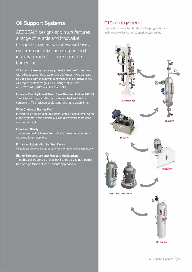
Oil Support Systems
AESSEAL® designs and manufactures a range of reliable and innovative oil support systems. Our vessel based systems can utilize an inert gas feed (usually nitrogen) to pressurise the barrier fluid.Whilst all of these systems are primarily designed to be used with oil as a barrier fluid, water and oil / water mixes can also be used as a barrier fluid with a number of the systems in the oil support system range (i.e. SP Range, AES-15™, AES-FV™, AES-28™ and API Plan 53B).
Increase Plant Uptime & Mean Time Between Failure (MTBF) The oil support system Range increases the life of sealing equipment. This reduces equipment repair and down time.
Wide Choice of Barrier Fluid Different oils can be used as barrier fluids on all systems. Some of the systems in this section will also allow water to be used as a barrier fluid.
Increased Safety The pressurised oil barrier fluid will stop hazardous products escaping to atmosphere.
Enhanced Lubrication for Seal Faces Oil acts as an excellent lubricant for the mechanical seal faces.
Higher Temperature and Pressure Applications The physical properties of oil allow it to be utilized as a barrier fluid on high temperature / pressure applications.
Oil Technology Ladder The oil technology ladder shows the progression of technology within our oil support system range
20 Oil Support Systems
3
1
2
SP Range
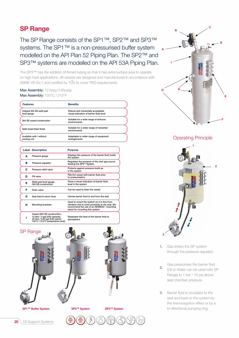
Features Benefits
Integral 304 SS weld padlevel gauge
304 SS vessel construction
Satin bead blast finish
Available with / withoutcooling coil
Robust and industrially acceptablevisual indication of barrier fluid level
Suitable for a wide range of arduousenvironments
Suitable for a wider range of industrialenvironments
Adaptable to wider range of equipmentarrangements
Label
A
Description
Pressure gauge
Purpose
Displays the pressure of the barrier fluid insidethe system
B Pressure regulator
C Pressure relief valve Protects against pressure build upin the system
E Weld pad level gauge,304 SS construction
Gives a visual indication of barrier fluid level in the system
F Drain valve Can be used to drain the vessel
G Seal feed & return lines Carries barrier fluid to and from the seal
H Mounting bracketsUsed to mount the system so it is free from vibration and in close proximity to the seal. We recommend the use of an AESSEAL® mounting stand for mounting this system
Regulates the pressure of the inert gas sourcefeeding the SP2TM System
D Fill valveFills the vessel with barrier fluid prior to pressurisation
IVessel (304 SS construction, 12 litre / 3 gal (US) capacity,25 litre / 6.60 gal (US) option,100°C / 212°F temperature limit)
Dissipates the heat of the barrier fluid toatmosphere
SP Range
The SP Range consists of the SP1™, SP2™ and SP3™ systems. The SP1™ is a non-pressurised buffer system modelled on the API Plan 52 Piping Plan. The SP2™ and SP3™ systems are modelled on the API 53A Piping Plan.The SP3™ has the addition of finned tubing so that it has extra surface area to operate on high heat applications. All vessels are designed and manufactured in accordance with ASME VIII Div.1 and certified by TUV to cover PED requirements.
Max Assembly: 10 barg (145psig) Max Assembly: 100°C / 212°F
••
Gas enters the SP system through the pressure regulator.
Gas pressurises the barrier fluid (Oil or Water can be used with SP Range) to 1 bar / 15 psi above seal chamber pressure.
Barrier fluid is circulated to the seal and back to the system by the thermosyphon effect or by a bi-directional pumping ring.
1.
2.
3.
Operating Principle
SP1™ Buffer System SP2™ System SP3™ System
D
G H
A
I
E
CB
F
Oil Support Systems 21
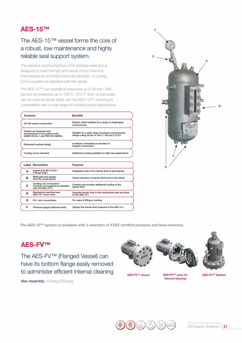
AES-15™
The AES-15™ vessel forms the core of a robust, low maintenance and highly reliable seal support system.The vessel is constructed from 316 stainless steel and is designed to meet the high end needs of the Chemical, Pharmaceutical and Petrochemical industries. A Cooling Coil is supplied as standard with the vessel.
The AES-15™ can operate at pressures up to 30 bar / 435 psi and temperatures up to 100°C / 212°F. Both oil and water can be used as barrier fluids with the AES-15™, ensuring its compatibility with a wide range of industrial pump applications.
AES-FV™
The AES-FV™ (Flanged Vessel) can have its bottom flange easily removed to administer efficient internal cleaning Max Assembly: 16 barg (232psig)
Features Benefits
316 SS vessel construction
Vessels are designed and manufactured in accordance with ASME VllI Div.1 and PED 2014/68/EU
Enhanced modular design
Cooling coil as standard
Robust vessel suitable for a range of challengingenvironments
Suitable for a wide range of arduous environments.Design rating 30 bar @ 100˚C / 435 psi @ 212˚F
Available in threaded as standard orflanged construction
Additional cooling available for high heat applications
AES-FV™ open for internal cleaning
AES-FV™ closed AES-FV™ System
E
A
F
B
D
C
Label
A
Description
Vessel (316 SS 15 litre /3.96 gal (US) )
Purpose
Dissipates heat of the barrier fluid to atmosphere
B Weld pad level gauge(316 SS construction) Visual indication of barrier fluid level in the vessel
CCooling coil connections(Cooling coil supplied as standardwith the AES-15TM)
Cooling coil provides additional cooling of thebarrier fluid
D Mechanical seal feed andAES-15TM return lines
Supplies barrier fluid to the mechanical seal and backto the AES-15TM
F Pressure gauge (optional extra) Diplays the barrier fluid pressure in the AES-15TM
E Fill / vent connections For ease of filling or venting
The AES-15™ system is available with a selection of ATEX certified pressure and level switches.

Oil Support Systems22
Operating Principle
PP/SOU™
The PP/SOU™ is an entry level alternative to the standard AESSEAL® PUMPPAC™ Range. The product is suitable for many industries. This is a high specification and low cost solution to forced circulation seal support systems. This system cannot be used in an ATEX environment.
Features Benefits
Specifically designed to be used in arange of non-high corrosive environments
API Plan 54 forced circulation system
The PP/SOUTM can be installed in a varietyof environments by interchanging the instrumentation options
High specification and low cost solution toforced circulation barrier fluid systems
Maximises barrier fluid heat dump potential
Uses the same proven technology and modular design as the standard AESSEAL®
PUMPPACTM Range
Label
B
Description
Motor (Aluminium body, weather proof IP55, 3 phase 0.55 KW 0.79Hp-230/400V-50/60Hz, 4 pole- 1450/1750 rpm)
Purpose
Drives the pump
C Pressure gauge (polycarbonate anti-impact body, brass wetted parts)
Displays the pressure of the barrier fluidfeeding the mechanical seal
A Manifold (Aluminium body, 5-50 bar / 72-725 psi)
Securely attaches the motor to thePUMPPACTM reservoir
DPump (Aluminium construction3.8 litres / 1.0 gal (US) per minute)
Supplies the barrier fluid to the mechanicalseal
EPressure control valve (Aluminium construction 5-50bar / 72-725 psi)
Controls the pressure of the barrier fluidfeeding the mechanical seal
F Suction filter (Carbon steel, 45 litre /12 gal (US) )
Cleans the barrier fluid feedingthe mechanical seal
G PUMPPACTM reservoir (painted carbon steel45 litre / 12 gal (US) )
Large surface area for barrier fluidcooling to atmosphere
C
A
D
E
F
G
B
3
1
2
Cool Barrier fluid is pumped from the PUMPPAC™ to the mechanical seal.
Barrier fluid passes through the mechanical seal and back to the PUMPPAC™ where it is cooled.
The back control valve controls the pressure in the line.
1.
2.
3.

Oil Support Systems 23
1
2
3
PP/01™
The AESSEAL® Oil PUMPPAC™ (PP/O1™) is an efficient and high performance forced circulation system.The product was developed to meet the requirements of the API Plan 54 Piping Plan, which maximizes heat dump potential for the more arduous pump applications. The maximum operating pressure of the standard PP/O1™ is 70 bar / 1016 psi.
A fully certified ATEX version of the PP/01™ is now available with a range of optional extras to suit all applications. AESSEAL® also offers a high flow pump option that can generate 12 litres / 3.17 gal (US) per minute (max pressure 35 bar / 508 psi).
Label
E
Description
Seal feed
Purpose
Is the point where the barrier fluid leaves the PUMPPACTM and travels to the mechanical seal
APump / motor assembly (Cast iron positive pump, 4 liters / 1.1 gal (US) per minute, Cast iron safe area motor)
D Fill cap Is the place where the reservoir can be filledwith barrier fluid
B Suction filter Cleans the barrier fluid as it is removed from the reservoir
C PUMPPACTM reservoir: (45 litres /12 gal (US) capacity, SS construction)
The large volume ensures e�cient cooling ofthe barrier fluid to atmosphere
F Back pressure control valve(SS construction)
Controls the pressure of the barrier fluidfeeding the seal
This is the heart of the system providing the mechanism for transferring the barrier fluid from the reservoir to the mechanical seal
Features Benefits
API Plan 54 forced circulation system
Enhanced modular design to beused on a range of high end applications
Capable of supplying split flows and a range of pressures for two or more mechanical seals
Maximizes barrier fluid heat dump potential
The PUMPPACTM can be installed in a variety of zoned environments by interchanging theinstrumentation options
Barrier fluid cooling of two or more mechanical seals can be accurately controlled
A
B
C
D
E
F
Cool barrier fluid is pumped from the PUMPPAC™ to the mechanical seal.
Barrier fluid passes through the mechanical seal and back to the PUMPPAC™ where it is cooled.
The back control valve controls the pressure in the line.
1.
2.
3.
Operating Principle
F
D
H
I
E
G
C
A
B
API Plan Systems24
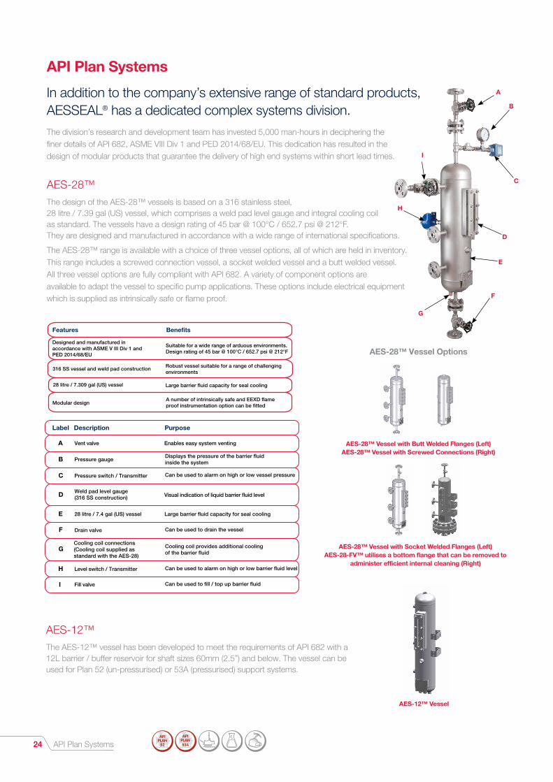
Designed and manufactured in accordance with ASME V III Div 1 and PED 2014/68/EU
316 SS vessel and weld pad construction
28 litre / 7.309 gal (US) vessel
Modular designA number of intrinsically safe and EEXD flame proof instrumentation option can be fitted
Large barrier fluid capacity for seal cooling
Robust vessel suitable for a range of challengingenvironments
Suitable for a wide range of arduous environments. Design rating of 45 bar @ 100°C / 652.7 psi @ 212°F
Features Benefits
AES-12™The AES-12™ vessel has been developed to meet the requirements of API 682 with a 12L barrier / buffer reservoir for shaft sizes 60mm (2.5”) and below. The vessel can be used for Plan 52 (un-pressurised) or 53A (pressurised) support systems.
AES-28™ Vessel Options
Label Description Purpose
28 litre / 7.4 gal (US) vessel Large barrier fluid capacity for seal coolingE
Weld pad level gauge(316 SS construction) Visual indication of liquid barrier fluid levelD
Cooling coil connections (Cooling coil supplied asstandard with the AES-28)
Cooling coil provides additional coolingof the barrier fluid
G
Drain valve Can be used to drain the vesselF
Fill valve Can be used to fill / top up barrier fluidI
Level switch / Transmitter Can be used to alarm on high or low barrier fluid level H
Pressure gaugeDisplays the pressure of the barrier fluidinside the systemB
Pressure switch / Transmitter Can be used to alarm on high or low vessel pressureC
Vent valve Enables easy system ventingA
API Plan Systems
In addition to the company’s extensive range of standard products, AESSEAL® has a dedicated complex systems division.The division’s research and development team has invested 5,000 man-hours in deciphering the finer details of API 682, ASME VIII Div 1 and PED 2014/68/EU. This dedication has resulted in the design of modular products that guarantee the delivery of high end systems within short lead times.
AES-28™The design of the AES-28™ vessels is based on a 316 stainless steel, 28 litre / 7.39 gal (US) vessel, which comprises a weld pad level gauge and integral cooling coil as standard. The vessels have a design rating of 45 bar @ 100°C / 652.7 psi @ 212°F. They are designed and manufactured in accordance with a wide range of international specifications.
The AES-28™ range is available with a choice of three vessel options, all of which are held in inventory. This range includes a screwed connection vessel, a socket welded vessel and a butt welded vessel. All three vessel options are fully compliant with API 682. A variety of component options are available to adapt the vessel to specific pump applications. These options include electrical equipment which is supplied as intrinsically safe or flame proof.
AES-12™ Vessel
AES-28™ Vessel with Socket Welded Flanges (Left) AES-28-FV™ utilises a bottom flange that can be removed to
administer efficient internal cleaning (Right)
AES-28™ Vessel with Butt Welded Flanges (Left) AES-28™ Vessel with Screwed Connections (Right)

API Plan Systems 25
Compact design The small footprint of the product enables its installation in areas with restricted space
Features Benefits
Lifting eye Enables e�cient and safe lifting of the product
Earthing boss Enables e�cient and safe electrical earthingof the product
Paint work suitable for on & o�shore Every 53B system is suitable for the environmentin which it is installed
Low centre of gravity
Allows a variety of larger accumulator options tobe applied within the modular design.Designed to take into consideration the detailsof API 682 4th Edition
Export quality packaging is standard
AESSEAL understands the importance of secureand e�ective packaging and guarantees that allcustomers will receive fully protected productto their sites
®
Label Description Purpose
Bladder accumulator Maintains barrier fluid pressure to the inboardand outboard seal faces
A
Non-return valveMaintains system pressure during filling and ensurestop up systems do not become contaminatedB
*Transmitters also available
Supports the system components and is painted tothe AESSEAL® o�shore paint specification to withstanda range of industrial environments
System standK
Vent valve Enables easy system ventingJ
Fill valve Can be used to fill / top up barrier fluidE
Drain valve Can be used to drain the vesselC
Double block and bleed valves Enables easy isolation and draining of the systeminstrumentation
G
Pressure gauge Displays the pressure of the barrier fluid insidethe system
I
Pressure switch / Transmitter Can be used to alarm on high or level vessel pressureH
System coolerDissipates the heat of the barrier fluid, a variety ofcooler types are availableF
Seal feed & return Supplies barrier fluid to and from the mechanical sealD
API Plan 53B
The AESSEAL® 53B system uses an innovative modular concept to facilitate efficient stock control enabling rapid delivery times. This highly versatile design concept enables bespoke 53B systems to be produced tailored to customer specific needs.The system pipe work is constructed from 316 stainless steel pipe work to offer resistance to a range of arduous environments. This system design is suitable for 66 bar @ 100°C / 957.25 psi @ 212°F. This system design is fully API 682 compliant and is available with a variety of component options. These options include electrical equipment which are supplied as intrinsically safe or flame proof.
C
E F
G
D
B
A
JIH
K

API Plan Systems26
API Plan 76
Compact 107™
API Plan 65
LSH
API Plan 75
The Compact 107™ is an innovative AESSEAL® specific design that combines the benefits of API Plans 53A, 53B and 54. The system can be used to supply pressurised barrier fluid to a number of seals.
Additional Piping Plans
Below are only a few examples of the various API Plans that are available. Contact the AESSEAL® complex systems division for quotes and more information.
API Piping Plan Booklet

Gas Panel 27
Gas Panel
The Gas Panel system is designed to supply inert gas (e.g. Nitrogen) to mechanical seals on processes that cannot tolerate contamination by water or oil barrier fluids.The self contained systems (Images 1 and 2) has a maximum inlet pressure of 14 bar / 203 psi and a maximum outlet pressure of 10 bar / 145 psi enabling it to be used on a wide range of applications. A high pressure 21 bar version (stainless steel) is also available instrumented
Ensures that a clean gas supply is feeding the seal
Protects the components from the industrial environment
Prevents product contamination of the gas panel duringupset conditions
Allows primary flow indication and secondary alarm conditionDual flow indicators
Non-return valve
Coalescing filter
Components are enclosed in asecure cabinet (this does not applyto the stainless steel versions)
Features Benefits
Ball valve
Check valve
Coalescing filter
Pressure regulator
Flow meter (high)
Flow meter (low)
Pressure gauge
Pressure switch*
Flow limit switch*
Valve can be closed to isolate the gas panel system to enable maintenance to be carried out
Protects the gas supply from process contamination
Cleans the gas supply to the seal
Regulates the pressure of the gas barrier feedingthe seal (10 bar / 145 psi maximum output pressure)
Alarms in the event of excess Nitrogen flow indicating seal failure
Displays the flow rate of gas feeding the seal
Displays the flow rate of gas feeding the seal
Displays the pressure of gas feeding the seal
Will warn of problems with the gas pressure
Label Description Purpose
A
B
C
E
F
G
H
I
D
Standard Gas Panel Schematic
Compressor Dry Gas Seal Support SystemsHigh quality compressor dry gas seal support systems engineered to customer requirements for all seal configurations and applications. Each AESSEAL® gas conditioning system contains the key API modules plus various enhancements derived from our own field experience, to ensure the highest degree of compressor dry gas seal reliability and longevity.
For every application AESSEAL® performs a detailed phase analysis in-house to determine the required level of gas conditioning.
GASSUPPLY
VENT SEALSUPPLY
Standard Gas Panel Image 1
Stainless Steel Gas Panel Image 2
C
B B
A A A
I G
FED H

SMART TRACK®28
SMART TRACK®
Designed to track and maintain a constant differential with fluctuations in process pressure.Patent pending isolating pressure tracking valve that will maintain a positive differential pressure between a reference input pressure (seal chamber / vessel pressure) and an output pressure (typically API Plan 53A) with the connection of a suitable supply (Typically nitrogen at a pressure greater than maximum operating barrier pressure). The device has an integrated isolation unit that will provide a physical barrier between product (seal chamber / vessel fluid) and the device.
Tracks pressure to maintain an optimum double seal environment
A compact alternative to complex seals & systems
Simple in line connection sand mountingErgonomic
Simplicity
Self regulating
Features Benefits
Transient and upset conditions handles with easeQuick response
No operator intervention required. Unit is supplied pre-setFactory set
GasVenting
GasSupply
OutletRegulatedPressure
InputReferencePressure
Gas venting
Gas supply
Outlet regulated pressure(to top up vessel)
Input reference line / pressure
Alternative input referenceline / pressure
Label Description Purpose
B
C
D
E
A
Depressurisation connection - pipe to safe area
Pressurisation connection - from a higher pressuresource i.e. N gas bottle or ring main2
Connection to vessel
Variable pressure source
Vent plug to remove air from reference line
B
C
D
A
E

SMART TRACK II™ 29
SMART TRACK II™
Patent pending variable back pressure valve. A unique & simple pressure tracking solution designed to track and maintain a constant differential with fluctuations in process pressure. Pressure tracking valve that will maintain a positive pressure differential between a reference input pressure (seal chamber) and an regulated barrier system back pressure (typically API Plan 54). The device has the option to fit an integrated isolation unit that will provide a physical barrier between product (seal chamber) and the active area of the device.
Tracks pressure to maintain an optimum double seal environment control
Transient and upset conditions handled with ease
Replaces complex control systems and over engineered solutions
Cost e�ective
Quick response
Self regulating
Features Benefits
No operator intervention possible, unit is supplied factory set
Factory set
Optimum mechanical seal conditions maintained in operation and upset conditions
Reliability
Label Description Purpose
A
B
C
E
D
F
Input reference line / pressure
Fluid circulation port inlet
Fluid circulation port outlet(to tank)
Bias spring (option available)
Factory set plug
Factory set plug fluid chamber
Variable pressure source
Circulation connection from seal
Circulation connection to tank
To set constant di�erential above reference pressure(A) 2bar (29psi), 4 bar (58psi) or 6 bar (87psi) available
Vent plug to remove air from reference line
Vent pressure transfer fluid seal - do not remove
E
A
D
B
C
F
SMART TRACK II™ Schematic With PUMPPAC™
A
B
PUMPPAC™ pump
SMART TRACK II™
Pressure gauge
PUMPPAC™ reservoir
Suction filter
Item Description
A
B
C
D
E
C
D
E

Top Up Trolley30
Label Description Purpose
A
B
D
F
G
Tank
Pressure gauge
To allow quick, easy manual connection anddisconnection of the supply hose (optional)
Hose
Stainless framework, to allow manoeuvringand steering
Framework
Fluid reservoir, nominally 100
Display supply pressure (optional)
6 meter (20ft) flexible hydraulic hose to connecttop-up unit to system
Quick release coupling
C Pressurising pump Hand Pump suitable up to 42barg
E Reservoir filler vent cap Reservoir fill and vent cap
Top Up Trolley
The TUP100™ are 100 litre (26 US gals) mobile barrier fluid Top Up Trolleys.The units are offered in Stainless Steel to suit the vast majority of industrial applications. The TUP100™ comes with 6m (20ft) of hydraulic flexible hose and include a hand pump and instrumentation pack that is rated to 42 bar (610 psi). The product is primarily designed to satisfy the needs of the oil and gas industry.
A BD
C
F
G
E
Modular system for practically all commonly usedbarrier fluid media
Operator friendlyMobile unit with integral breaking system
Full stainless steel construction
Features Benefits
Reliable and robust filling operationHand pump delivery
AESSEAL® Plan 53B seal support system being filled / topped up by the TUP100™

Optional Extras 31
Cooler OptionsLiquid - Helicoil CoolerThe AESSEAL® Cooler is constructed from 316 stainless steel tube and cast iron casing (cast steel & cast 316 steel casting options available).
This robust product is a very efficient seal cooler used on API Piping Plan 21, 22 and 23 arrangements. The product can also be used in conjunction with other products in the systems division range to provide additional cooling on high heat applications.
Convection - Finned TubingFinned tubing provides additional convection cooling on high heat applications. The tubing is constructed from 316 SS schedule 40 pipe with aluminium wound fin and 316 SS turbulator. It is available in banks of 2 and 4 depending on the amount of heat that needs to be removed. Butt and socket weld flanges are available for each bank option.
Python™The AESSEAL® Python is an advanced air cooled heat exchanger for cooling mechanical seal barrier/buffer/flush fluids. Air cooling is achieved through natural convection without the need for cooling water. The unit consists of a tube formed into a coil, terminated with inlet and outlet manifolds. The Python is available in both 8m single (Figure1) and 16m dual coil (Figure 2) arrangements.
Air Blast CoolerThe Air Blast Cooler uses a combination of high performance cooling elements and high capacity, compact AC electrically powered fans to give long trouble-free operation in arduous applications. The compact design provides the highest cooling performance in heat dissipation whilst minimizing the space required.
• Cooling range 0-5 kW
• AC motors in 230 / 400 Volt 50 / 60 Hz
• Maximum working pressure 16 bar / 232 psi
• Also available with ATEX Zone 1 Antistatic Exd motor
Finned Tubing Cross SectionFinned Tubing
Figure 1 Single Coil
Figure 2 Dual Coil

Optional Extras32
Optional ExtrasVessel Options• Mounting stand - Standard and telescopic options
• Level switch - Safe area, intrinsically safe and explosion proof options
• Pressure switch - Safe area, intrinsically safe and explosion proof options
• PTFE lined braided flexible hose kit - SS construction
• Hard pipe kit - SS construction
• Finned tubing kit - Includes all necessary connections
• In-line water filter kit - Includes all necessary connections
• Cooling coil - 316 SS construction
• Hand pumps - Water and oil options
• Air / Nitrogen supply regulator - Zinc alloy construction / SS option
• Vessel kits - Consists of a vessel and decals only
• Top up Trolley - For use on systems pressurised by an external gas supply
• Pressure gauge - All SS option
PUMPPAC™ Options• ATEX certified oil PUMPPAC™
• Explosion proof motor - Cast iron construction and ATEX certified
• Top entry low level switch - Safe area, intrinsically safe and explosion proof options
• High / Low pressure switch - Safe area, intrinsically safe and explosion proof options
• Back pressure valve - SS construction
• Suction filter - SS construction
• Flow divider - Splits the flow to feed multiple mechanical seals (the amount of seals that can be fed depends on the model of PUMPPAC™ being used, please consult your local AESSEAL® representative for more information)
• High flow oil pump - For use on oil PUMPPAC™ only
• Pressure gauge - SS construction
XY and Y Telescopic System Stands
PUMPPAC™
EExd Pressure Switch
“y”
“y”“x”
Gas Panel Options• Pressure switch - Safe area, intrinsically safe and explosion proof options
• Flow switch - Intrinsically safe & explosion proof option

Optional Extras 33
Heat GuardIndustrial applications are hazardous places for personnel to work especially when hot oil seal support vessels are in use. Health and Safety Regulations stipulate that protective clothing and guarding should be provided where objects with surface temperatures greater than 50°C (122°F) are present.
The AESSEAL® Heat Guard is ideal where SP range (eg. SSE12) and AES-15 vessels are in use at temperatures greater than the health and safety limit. Fitted to the vessel the Heat Guard remains 40°C (104°F) cooler than the vessel body and so ensuring that site personnel cannot injure themselves by accidentally touching the dangerously hot vessel body.
Retrofittable design allows it to be installed onto vessels currently in operation once they have cooled to a temperature that is safe to touch.
EasyClean™Pressure Systems Designed for the Pharmaceutical, Food & Beverage Sectors. EasyClean™ can be used as part of an API Plan 52 and 53a seal support systems. Features
• Customer effective solution
• Fully accessible
• 304 Stainless Steel constructions
Benefits
• Quick release clamp allows vessel to be opened for cleaning and inspection
• Ideal in Pharmaceutical and Food & Beverage industries
• Simple patent pending design solving critical issues in applications requiring higher standards of hygiene
ICEGUARD™The AESSEAL® ICEGUARD™ is ideal for commercial and industrial applications where water is prone to freeze in and around the seal support system.
The ICEGUARD™ continually senses the temperature of the water inside the seal support system. When the water temperature approaches freezing, and freeze damage is imminent, the thermal actuator modulates the valve open. When the makeup water temperature returns to the safe range, the valve then modulates closed, minimizing water loss. The flow generated prevents the liquid inside the system from freezing.
The ICEGUARD™ is designed to be:
• Self automated
• Installed on the system and ignored
• Free from electronics
• Provide 24/7 freeze protection 365 days per year
The ICEGUARD™ comes as a 2 piece product.
• The first protects the closed loop system to and from the mechanical seal from freezing
• The second protects the water feed line into the vessel from freezing
With both installed correctly, the ICEGUARD™ will offer effective freeze protection to the entire seal support system.

Systems Order Coding Guide34
VSE/SP02
VSE/SW02
VSE/SW02-25
OLD STOCK CODE
Standard Seal Support Systems Order Coding GuideThe systems division has established a new order code guide to simplify the process of ordering a standard seal support system. The new codes ensure that customers order the exact product they require and remove the need for developing AZA or MZM System codes when ordering products with optional extras. Please see the tables below for details of old stock codes, the new stock code and an explanation of how to form the new stock code.
VSE/SP02-25 With explosion proof low level switch
VSE/SP02-SS (US) Fully stainless components
VSE/SW3-25 With safe area pressure switch and
stand
VSE/SW03-25-CC-US
VSE/P212--SA----A-
VSE/W210--SA----A-
VSE/W225--SA----A-
VSE/W325CCSA----H-
NEW STOCK CODE
VSE/P212--SAEC--A-
VSE/P212SS---F-
VSE/W325--SAS-A-GA
OLD STOCK CODE NEW STOCK CODE
SYSTEM CODE (1-3) This refers to the type of vessel a customer will be using with the seal support system. All standard systems use a 10, 12 or 25 litre SSE type vessel so please enter VSE for this part of the order code.
SYSTEM TYPE (5-6) This defines the type of system a customer needs, i.e. P2 for a standard gas pressurised system, W2 for a standard water management system or WC for a condensate system. P1 = Buffer systems for use with oil and water (See page 20) P2 = Gas pressurised system (See page 20) P3 = Gas pressurised system with the addition of finned tubing for high heat applications (See page 20) W2 = Standard water management system using plant water line as water and pressure source (See page 15) W3 = Standard water management system using plant water line as water and pressure source with addition of finned tubing for high heat applications (See page 15) WF = Flow Fuse™ water management system (See page 16) WM = Low cost water management system utilizing the full pressure in the plant water line (See page 14) WP = Low cost water management system, with weld pad level gauge, utilizing the full pressure in the plant water line (See page 14) WC = Water management system specifically designed for condensate applications (See page 17)
VESSEL SIZE (7-8) Relates to the capacity of the vessel a customer is ordering. Please note that with W2, W3, WM & WP type systems, 10 litres is the standard, but with P1, P2 & P3 type systems the 12 litre weld pad is the standard. 10 = White powder coat finish as standard, no weld pad level gauge 12 = Shot bead blast finish and integral weld pad level gauge as standard 15 = Shot bead blast finish, integral weld pad and cooling coil as standard (option for WC system only) 25 = There are 2 options available (type of system will determine the option used)
1. White powder coat with no weld pad level gauge 2. Bead blast with integral weld pad level gauge
COOLING COIL (9-10) Add CC when ordering a system incorporating a cooling coil
COMPONENT MATERIAL (11-12) When ordering a system with standard component configurations, please choose SA. If it is to be a fully stainless system (all components in stainless steel), then please chose SS (only available for W2, W3, P1, P2 & P3 systems). Please note that when ordering a SS system it will be supplied with braided hose as standard, therefore when ordering a SS system, please choose option E or F in the hose option section.
SA = System with standard components SS = System with fully stainless components (only an option on W2, W3, P1, P2 & P3 systems)
New Stock Code Explanation 35
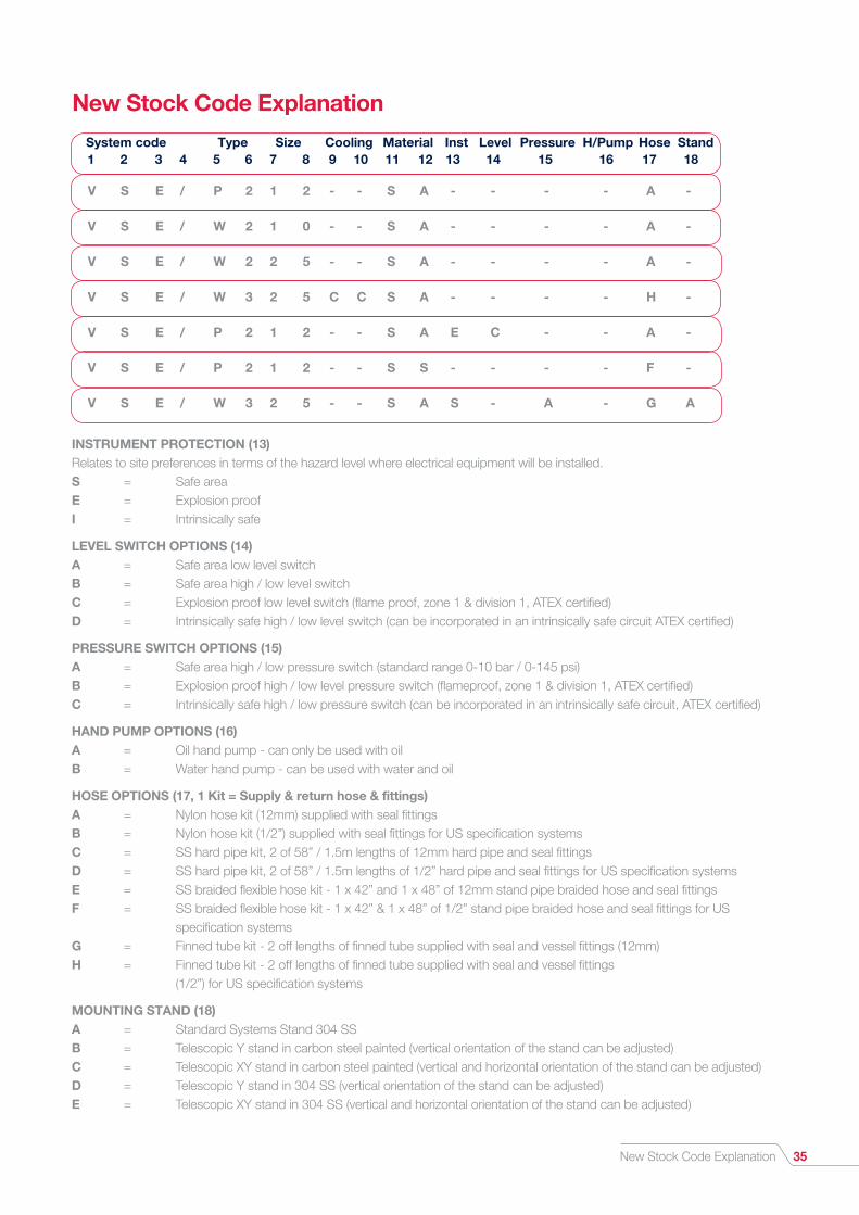
New Stock Code Explanation
V S E / P 2 1 2 - - S A - - - - A -
V S E / W 2 1 0 - - S A - - - - A -
V S E / W 2 2 5 - - S A - - - - A -
V S E / W 3 2 5 C C S A - - - - H -
V S E / P 2 1 2 - - S A E C - - A -
V S E / P 2 1 2 - - S S - - - - F -
V S E / W 3 2 5 - - S A S - A - G A
1 2 3 4 5 6 7 8 9 10 11 12 13 14 15 16 17 18 System code Type Size Cooling Material Inst Level Pressure H/Pump Hose Stand
INSTRUMENT PROTECTION (13) Relates to site preferences in terms of the hazard level where electrical equipment will be installed. S = Safe area E = Explosion proof I = Intrinsically safe
LEVEL SWITCH OPTIONS (14) A = Safe area low level switch B = Safe area high / low level switch C = Explosion proof low level switch (flame proof, zone 1 & division 1, ATEX certified) D = Intrinsically safe high / low level switch (can be incorporated in an intrinsically safe circuit ATEX certified)
PRESSURE SWITCH OPTIONS (15) A = Safe area high / low pressure switch (standard range 0-10 bar / 0-145 psi) B = Explosion proof high / low level pressure switch (flameproof, zone 1 & division 1, ATEX certified) C = Intrinsically safe high / low pressure switch (can be incorporated in an intrinsically safe circuit, ATEX certified)
HAND PUMP OPTIONS (16) A = Oil hand pump - can only be used with oil B = Water hand pump - can be used with water and oil
HOSE OPTIONS (17, 1 Kit = Supply & return hose & fittings) A = Nylon hose kit (12mm) supplied with seal fittings B = Nylon hose kit (1/2”) supplied with seal fittings for US specification systems C = SS hard pipe kit, 2 of 58” / 1.5m lengths of 12mm hard pipe and seal fittings D = SS hard pipe kit, 2 of 58” / 1.5m lengths of 1/2” hard pipe and seal fittings for US specification systems E = SS braided flexible hose kit - 1 x 42” and 1 x 48” of 12mm stand pipe braided hose and seal fittings F = SS braided flexible hose kit - 1 x 42” & 1 x 48” of 1/2” stand pipe braided hose and seal fittings for US specification systems G = Finned tube kit - 2 off lengths of finned tube supplied with seal and vessel fittings (12mm) H = Finned tube kit - 2 off lengths of finned tube supplied with seal and vessel fittings (1/2”) for US specification systems
MOUNTING STAND (18) A = Standard Systems Stand 304 SS B = Telescopic Y stand in carbon steel painted (vertical orientation of the stand can be adjusted) C = Telescopic XY stand in carbon steel painted (vertical and horizontal orientation of the stand can be adjusted) D = Telescopic Y stand in 304 SS (vertical orientation of the stand can be adjusted) E = Telescopic XY stand in 304 SS (vertical and horizontal orientation of the stand can be adjusted)

UK Sales & Technical advice:AESSEAL plcMill CloseBradmarsh Business ParkRotherham, S60 1BZUnited Kingdom
Tel: +44 (0) 1709 369966Fax: +44 (0) 1709 720788E-mail: [email protected]
USA Sales & Technical advice:AESSEAL Inc.355 Dunavant DriveRockford, TN. 37853USA
Tel: +1 865 531 0192Fax: +1 865 531 0571E-mail: [email protected]
For further information and safe operating limits contact our technical specialists at the locations below.
Distributed by:
Important: Since the conditions and methods of use of this product are beyond our control, AESSEAL plc expressly disclaims any and all liability resulting or arising from any use of this product or reliance on any information contained in this document - AESSEAL plc standard conditions of sale apply. All sizes are subject to manufacturing tolerances. We reserve the right to modify
specifications at any time. AESSEAL® is a Registered Trademark of AESSEAL plc, AESSEAL plc recognizes all trademarks and trademark names as the property of their owners.
Use double mechanical seals with hazardous products.
Always take safety precautions:
• Guard your equipment
• Wear protective clothing
WARNING
‘Our purpose is to give our customers such exceptional service that they need never consider alternative sources of supply.’
To experience the exceptional, please contact your local representative. Discover full details on our website:
www.aesseal.com
LN-UK/US-SYSPROD-03d Copyright © 2016 AESSEAL plc 07/2016