Embed Size (px)
Citation preview

Seal Analysis
Jeremy OsguthorpeMitchell WoolfJon Blotter
7 / 12 / 2007

Project Objectives
• Develop a finite element model of the seal using the geometry model provided.
• Using generic material properties determine the displacement and stress as functions of time using 80 psi and 100 psi instantaneous pressure loads.
2

Model Assumptions
• Constraining Seal – The metal cage was removed from the model and the effects of
the cage were applied as boundary conditions.
• Diaphragm Material Properties– Density = .00106 lbm/in^3– Modulus of Elasticity = 3,500 psi– Poisson’s Ratio ≈ 0.50– Damping Coefficient = 0.1– Isotropic Material

Model Assumptions
• Loading– The pressure will reach a maximum value
within 0.0001 sec. and then remains constant throughout the analysis. This is a perfect (instantaneous) pressure loading. A flow analysis could be done to verify this result.
– A uniform pressure distribution is applied over the diaphragm

Analysis Procedure• Meshed Seal
– The seal was meshed using a 2D surface mesh followed by a solid tetra mesh.
– The mesh element size is a result of refining the seal until there was a convergence of results.

Analysis Procedure• Constraining Seal
– The seal was constrained as shown in the figures. Appropriate surfaces were selected to represent the effect of the gun barrel and cage on the seal.
-Constraints A were constrained in the direction of the barrel-Constraints B were constrained in the radial direction-Constraints C were constrained in all directions

Analysis Procedure• Applying Pressure to the Seal
– A dynamic load was applied to the appropriate surfaces of the seal as shown. The figure is a profile view of how the pressure is applied to the entire seal.
– Uniform pressure loads of 80 psi and 100 psi were used in the static and transient analysis.
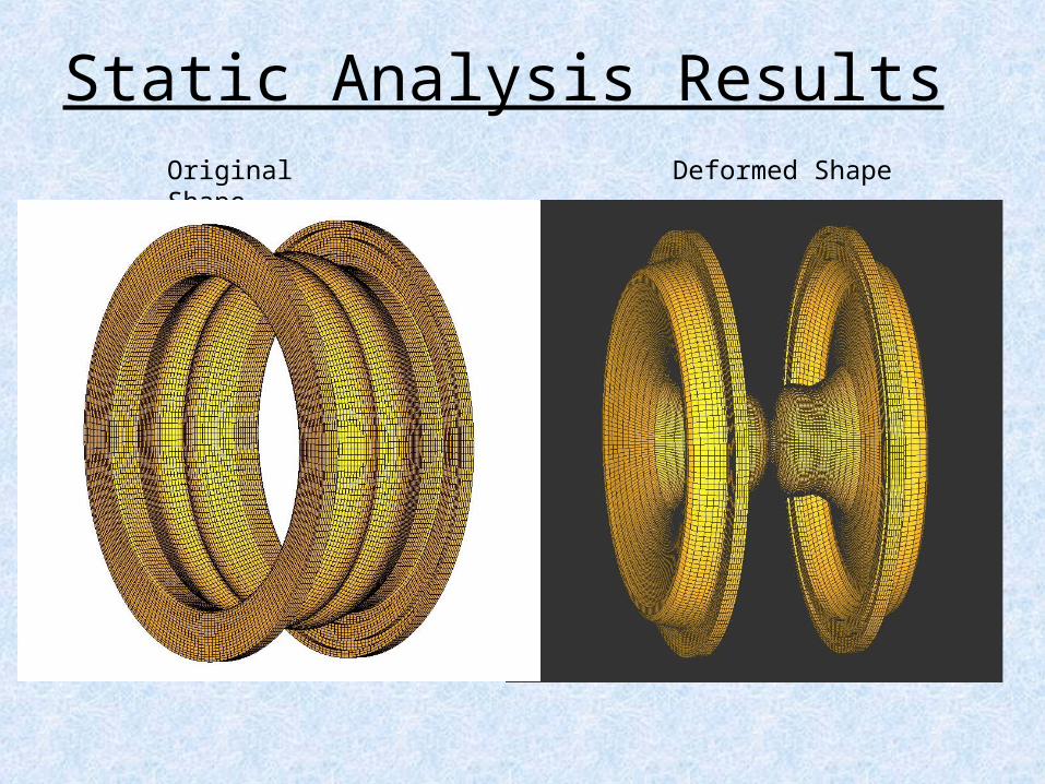
Static Analysis ResultsOriginal Shape Deformed Shape
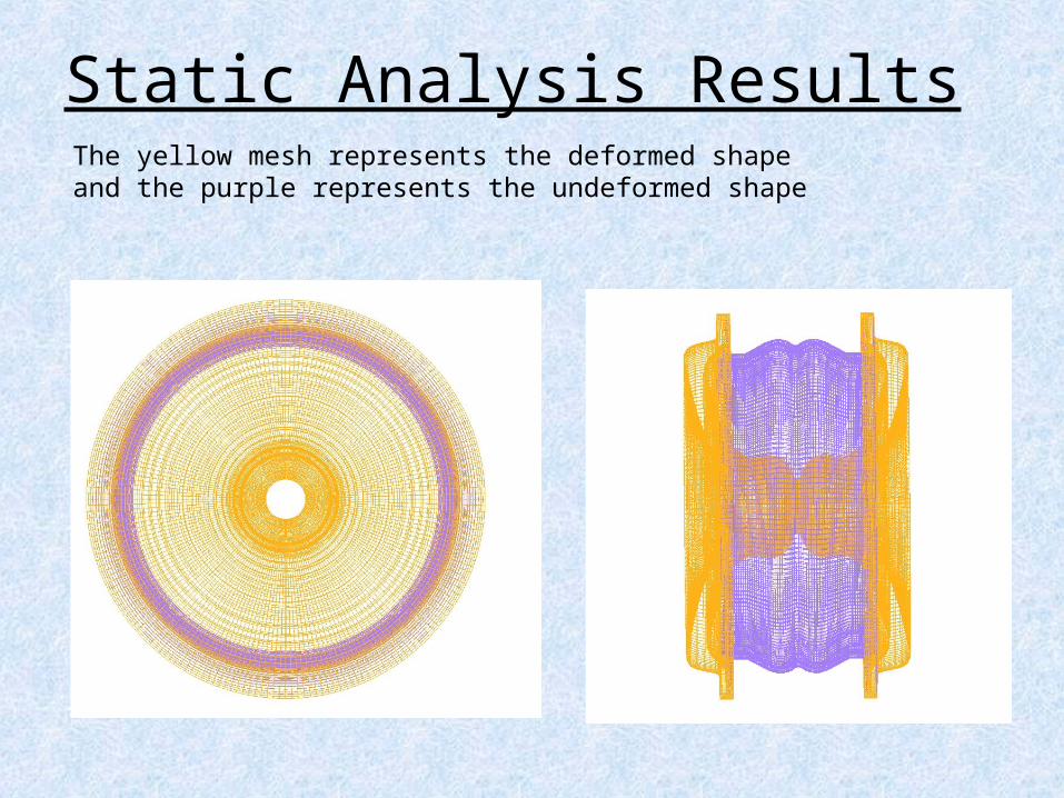
Static Analysis ResultsThe yellow mesh represents the deformed shape and the purple represents the undeformed shape

Static Analysis Results
Figure- Side view of deformed shape
Figure- The yellow mesh represents the deformed shape and the purple represents the undeformed shape

Static Analysis Results
• Stress on the Seal– The stresses throughout the seal are shown in the
figures according to color contour on the following slide
– The maximum stress experienced by the seal is 3,430 psi.
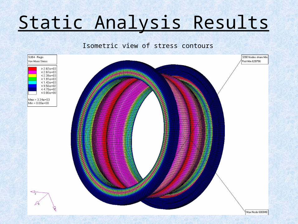
Static Analysis ResultsIsometric view of stress contours

Transient Analysis Results
• Transient analysis requires large amounts of computer processing resulting in large amounts of computation time.
• Transient analysis of the entire seal is redundant and is avoidable due to the symmetrical geometry. A single point inside of the seal was chosen for analysis. This point was chosen because it experiences the largest displacement and is a point of interest in relation to the paintball.

Transient Analysis Results
• The transient results are plotted on the following slide.
• The load is applied at a time of 0.001 seconds. The load is nearly instantaneous. The maximum displacement of the diaphragm is reached approximately 0.001sec later at a time of 0.002 sec.
• The diaphragm oscillates for approximately 15 milliseconds and then finally settles at a displacement of 0.328”. This displacement value was also confirmed using static analysis.

Static Analysis ResultsIsometric view of stress contours – 100 psi

Static Analysis ResultsTop view of stress contours – 100 psi

Static Analysis ResultsSide view of stress contours – 100 psi

Transient Analysis Results Dynamic displacements - inside of the seal with a load - 100 psi

Transient Analysis Results Dynamic displacements - inside of the seal - 80 psi

Transient AnalysisNominal dimensions of seal

Transient AnalysisMaximum displacement with 100 psi
Seal will fully close under these conditions (inner diameter = 0.0”)

Transient AnalysisFinal displacement values for 100 psi
Inner Diameter = 0.093”

Transient AnalysisMaximum displacement values for 80 psi
Inner Diameter = 0.147”

Transient AnalysisFinal displacement values for 80 psi
Inner Diameter = 0.223”

Analysis Summary Conclusions
• For the 100 psi load, the maximum displacement of 0.376” was reached in ~1 msec. The steady state displacement reached at ~12 msec is ~ 0.325”. The maximum stress experienced by the seal was 3,430 psi.
• For the 80 psi load, the maximum displacement of 0.310”
was reached in ~1 msec. The steady state displacement reached at ~10 msec is ~ 0.262”.