Embed Size (px)
Citation preview

Seagate Technology
DAT Tape Drives and Autoloaders
SCSI Manual
February 1997
Part Number 10002663–003

FCC Notice
The equipment referenced in this manual generates and uses radio frequencyenergy and if not installed and used properly—that is, in strict accordance withthe manufacturer's instructions—may cause interference to radio and televisionreception. It has been type tested and found to comply with the limits for aClass B computing device in accordance with the specifications in Part 15 ofFCC Rules, which are designed to provide reasonable protection against suchinterference in a residential installation. However, there is no guarantee thatinterference will not occur in a particular installation. If this equipment doescause interference to radio or television reception, which can be determined byturning the equipment on and off, you are encouraged to try to correct theinterference by one or more of the following measures:
Reorient the receiving antenna.
Relocate the computer with respect to the receiver.
Move the computer into a different outlet so that the computer and receiverare on different branch circuits.
If necessary, you should consult the dealer or an experienced radio/televisiontechnician for additional suggestions. You may find the following bookletprepared by the Federal Communications Commission helpful:
How to Identify and Resolve Radio-TV Interference Problems
This booklet (Stock No. 004-000-00345-4) is available from the U.S. GovernmentPrinting Office, Washington, DC 20402.
Warning: Changes or modifications made to this equipment which have notbeen expressly approved by Conner Peripherals, Inc. may cause radio andtelevision interference problems that could void the user's authority to operatethe equipment.
Further, this equipment complies with the limits for a Class B digital apparatusin accordance with Canadian Radio Interference Regulations.
Cet appareil numérique de la classe B est conforme au Règlement sur brouillageradioélectrique, C. R. C., ch. 1374.
Seagate and the Seagate logo are registered trademarks of Seagate Technology.All other trademarks mentioned in this manual are the property of theirrespective owners.
Copyright 1997, Seagate TechnologyAll rights reserved.
Document No. 10002663-003

Important Information About This Manual
All information contained in or disclosed by this document is consideredproprietary by Seagate Technology. By accepting this material, the recipientagrees that this material and the information contained therein are held inconfidence and in trust and will not be used, reproduced in whole or in part, norits contents revealed to others, except to meet the purpose for which it wasdelivered. It is understood that no right is conveyed to reproduce or translateany item herein disclosed without express written permission from SeagateTechnology.
Seagate Technology provides this manual "as is," without warranty of any kind,either expressed or implied, including, but not limited to, the impliedwarranties of merchantability and fitness for a particular purpose. SeagateTechnology reserves the right to change, without notification, the specificationscontained in this manual.
Seagate Technology assumes no responsibility for the accuracy, completeness,sufficiency, or usefulness of this manual, nor for any problem that might arisefrom the use of the information in this manual.

DAT Drive SCSI Manual Page v
Table of Contents
1 Introduction 1
Overview 1Drive Models 1About This Manual 2
2 Interface 3
Overview 3ANSI SCSI Bus Standards 3Cabling and Connectors 3
Signal Descriptions 4Command Set Description 5ANSI X3.131, 199X Conformance Statement (SCSI-2) 7SCSI Bus Protocol 8Waiting and Control Phases 8
Nonarbitrating Systems 9Arbitrating Systems 9
Selection and Reselection Phases 11Select With Attention 11Identify Message 12
Information Transfer Phases 12Asynchronous Data Transfer 13Synchronous Data Transfer 15
Command Phase 16Data Phase 16
Data-In Phase 16Data-Out Phase 16
Status Phase 16Message Phase 17
Message-In Phase 17Message-Out Phase 17
Command Description Block 17Logical Unit Support 19SCSI Message Descriptions and Definitions 20SCSI Status Code Descriptions and Definitions 24Attention Condition 25Reset Condition 25Unit Attention Condition 25Buffered Mode 26Immediate Function 26Residual Length Function 26Disconnect/Reconnect Function 27SCSI Memory Address Pointers 28

Table of Contents
Page vi DAT Drive SCSI Manual
Current Data Pointers 28Saved Data Pointers 29
Early Warning Function 29Error Reporting 29
Soft Errors 29Hard Errors 29
SCSI Bus Timing 30Variable and Fixed Mode Recording 31Autoloader Operation 32
Sequential Operation 33SCSI Direct-Access Operation 33General SCSI Information 33Addressing 34General Operation 34
3 Commands 37
Introduction 37Command Reference List 37Conventions 38
Command Descriptor Blocks (CDBs) 38Command Descriptor Block Formats 38Command Descriptor Block Field Descriptions 39Flag and Link Bit Descriptions 39
CHANGE DEFINITION (40h) 41CHANGE DEFINITION Command Descriptor Block 41Command Descriptor Block Field Description 42Conditions for Changing Definitions 42Completion Status 42
ERASE (19h) 43ERASE Command Descriptor Block 43Command Descriptor Block Field Descriptions 43Completion Status 44
EXCHANGE MEDIUM (Autoloader Only) (A6h) 45EXCHANGE MEDIUM Command Descriptor Block 45Command Descriptor Block Field Descriptions 45Completion Status 46
INITIALIZE ELEMENT STATUS (AutoloaderOnly) (07h) 47
INITIALIZE ELEMENT STATUS Command Descriptor Block 47Completion Status 47
INQUIRY (12h) 48INQUIRY Command Descriptor Block 48Command Descriptor Block Field Descriptions 48Standard INQUIRY Data Format 49Standard INQUIRY Data Format Field Descriptions 50INQUIRY Drive Serial Number Data Format Page 51
Table of Contents
DAT Drive SCSI Manual Page vii
Drive Serial Number Data Format Page Field Description 52Completion Status 52
LOAD/UNLOAD (1Bh) 53LOAD/UNLOAD Command Descriptor Block 53Command Descriptor Block Field Description 53Completion Status 54
LOCATE (2Bh) 55LOCATE Command Descriptor Block 55Command Descriptor Block Field Description 55LOCATE and BT Bit 56Completion Status 57
LOG SELECT (4Ch) 58LOG SELECT Command Descriptor Block 58Command Descriptor Block Field Description 59Errors Detected in Command Descriptor Block 59Use of the PC Bits 59LOG SELECT Parameter Data 61
LOG SENSE (4Dh) 66LOG SENSE Command Descriptor Block 66Command Descriptor Block Field Description 67Using Page Control Bits 68Using the Parameter Pointer Field 69LOG SENSE Pages 69Completion Status 79
MODE SELECT (15h) 80MODE SELECT Command Descriptor Block 80Command Descriptor Block Field Description 81MODE SELECT Parameters 81Parameter List Header Field Descriptions 82Parameter List—Block Descriptor 82Parameter List—Block Descriptor Field Descriptions 83Mode Page Format 83Completion Status 95
MODE SENSE (1Ah) 96MODE SENSE Command Descriptor Block 96Command Descriptor Block Field Descriptions 97MODE SENSE Parameters 98Parameter List Header Field Descriptions 99Parameter List—Block Descriptor 100Parameter List Block Descriptor Field Descriptions 100Mode Page Format 100Completion Status 111
MOVE MEDIUM (Autoloader Only) (A5h) 112MOVE MEDIUM Command Descriptor Block 112Completion Status 113
PREVENT/ALLOW Media Removal (1Eh) 114PREVENT/ALLOW Media Removal Command Descriptor Block 114Command Descriptor Block Field Description 114Completion Status 115
Table of Contents
Page viii DAT Drive SCSI Manual
READ (08h) 116READ Command Descriptor Block 116Command Descriptor Block Field Descriptions 116Description of the READ Command 117Completion Status 121
READ BLOCK LIMITS (05h) 122READ BLOCK LIMITS Command Descriptor Block 122Command Descriptor Block Field Description 122Block Size Definition 122Completion Status 123
READ DATA BUFFER (3Ch) 124READ DATA BUFFER Command Descriptor Block 124Command Descriptor Block Field Description 124READ DATA BUFFER Header 125READ DATA BUFFER Header Field Descriptions 125Completion Status 125
READ ELEMENT STATUS (AutoloaderOnly) (B8h) 126
READ ELEMENT STATUS Command Descriptor Block 126Element Status Data 126Element Status Data Header 127Completion Status 130
READ POSITION (34h) 131READ POSITION Command Descriptor Block 131READ POSITION Data Format 131READ POSITION Data Format Field Descriptions 132Completion Status 132
RECEIVE DIAGNOSTIC RESULTS (1Ch) 133RECEIVE DIAGNOSTIC RESULTS Command Descriptor Block 133Command Descriptor Block Field Description 133Completion Status 134
RELEASE UNIT (17h) 135RELEASE UNIT Command Descriptor Block 135Command Descriptor Block Field Description 135Completion Status 136
REQUEST BLOCK ADDRESS (02h) 137REQUEST BLOCK ADDRESS Command Descriptor Block 137Command Descriptor Block Field Description 137REQUEST BLOCK ADDRESS Data Format 137REQUEST BLOCK ADDRESS Data Field Description 138Completion Status 138
REQUEST SENSE (03h) 139REQUEST SENSE Command Descriptor Block 139Sense Data Format 139Sense Data Field Descriptions 140Priority and Definition of Sense Keys 143

Table of Contents
DAT Drive SCSI Manual Page ix
Additional Sense Code and Code Qualifier 143Autoloader Error Codes 147Completion Status 148
RESERVE UNIT (16h) 149RESERVE UNIT Command Descriptor Block 149Command Descriptor field Description 150Completion Status 150
REWIND (01h) 151REWIND Command Descriptor Block 151Command Descriptor field Description 151Completion Status 152
SEEK BLOCK (0Ch) 153SEEK BLOCK Command Descriptor Block 153Command Descriptor field Description 153Completion Status 154
SEND DIAGNOSTIC (1Dh) 155SEND DIAGNOSTIC Command Descriptor Block 155Completion Status 156
SPACE (11h) 157SPACE Command Descriptor Block 157Command Descriptor Block Field Descriptions 158Space-by-Count Functions 158Space-by-Position Functions 159Space and the RSMK Bit 159Completion Status 160
TEST UNIT READY (00h) 161TEST UNIT READY Command Descriptor Block 161TEST UNIT READY Detailed Operation 161Completion Status 162
VERIFY (13h) 163VERIFY Command Descriptor Block 163Command Descriptor Block Field Description 163Data Transfers with the VERIFY Command 163Completion Status 164
WRITE (0Ah) 165WRITE Command Descriptor Block 165Command Descriptor Block Field Description 166Completion Status 166
WRITE DATA BUFFER (3Bh) 167WRITE DATA BUFFER Command Descriptor Block 167Command Descriptor Block Field Descriptions 167WRITE DATA BUFFER Data Header 169Completion Status 169

Table of Contents
Page x DAT Drive SCSI Manual
WRITE FILEMARKS (10h) 170WRITE FILEMARKS Command Descriptor Block 170Command Descriptor Block Field Descriptions 170Completion Status 171
DAT Drive SCSI Manual Page 1
Introduction
Overview
The Seagate Digital Audio Tape (DAT) drives are designed for computerenvironments requiring high performance, high capacity data storage. DATdrives are available as an internal device in either a 3.5-inch or half-high 5.25-inch configuration or as an external subsystem. The DAT Autoloaders contain aDAT drive internal to the box which acts as the drive mechanism.
The drives contain an embedded, single-ended Small Computer SystemsInterface (SCSI) controller that supports SCSI (ANSI X3.131, 1986) and SCSI-2(ANSI X3.T92). These drives provide synchronous or asynchronous SCSI and ahigh speed burst rate of 5 MB/second. The internal drive form factors aretailored for easy installation in today's computers, and the full-featuredembedded SCSI controller facilitates easy integration into a variety of systems.
Drive Models
This manual provides detailed information about the SCSI interface and SCSIcommands that apply to all models of DAT drives and DAT Autoloaders.
These drives offer electronically erasable, programmable, read-only memory(flash EEPROM) for SCSI firmware, which enables qualified Seagate OEMs todownload revised firmware to the drive via two methods: using the SCSI bus orusing a specialized Seagate firmware tape cartridge.
1
Introduction Chapter 1
Page 2 DAT Drive SCSI Manual
About This Manual
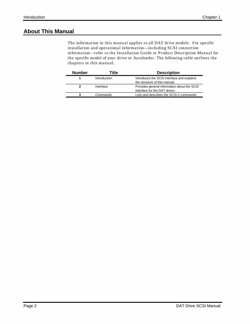
The information in this manual applies to all DAT drive models. For specificinstallation and operational information—including SCSI connectioninformation—refer to the Installation Guide or Product Description Manual forthe specific model of your drive or Autoloader. The following table outlines thechapters in this manual.
Number Title Description1 Introduction Introduces the SCSI interface and explains
the structure of this manual.2 Interface Provides general information about the SCSI
interface for the DAT drives.3 Commands Lists and describes the SCSI-2 commands.

DAT Drive SCSI Manual Page 3
Interface
Overview
The Seagate DAT drives are designed to operate with the Small ComputerSystem Interface (SCSI) bus. This chapter discusses SCSI bus operation as itpertains to drive functions.
SCSI is a standard interface established to support peripheral equipment suchas printers, tape drives, magnetic disks, optical disks for microcomputers andother computer systems. The SCSI bus can support up to eight devicesconsisting of any multiple of host adapters and peripheral devices.
The DAT drives comply with SCSI-1 (ANSI Standard X3.131-1986) and SCSI-2(ANSI SCSI Draft Revision 10H). In a few cases, vendor unique features areavailable. These features are compatible with the SCSI standards.
The interface is an eight-port, daisy-chained bus using eighteen signal lines:nine data-bit signal lines and nine control lines. The nine data-bit lines aremade up of eight signal lines and one parity-bit line. The remaining nine linesprovide control and status signals to coordinate data transfer operationsbetween the host controller and the selected drive.
The drives have an internal SCSI controller integrated into the driveelectronics. Each device ID on the SCSI bus may drive up to 8 logical units(LUN). The DAT drive supports only LUN 0, except for the Autoloader whichalso uses LUN 1.
ANSI SCSI Bus Standards
In addition to the information presented in this manual, we recommend that forSCSI-1 you read the ANSI X3.131 1986 standard and for SCSI-2, the ANSIWorking Draft Revision 10 standard before writing host software drivers. Also,see the conformance statements, which are given in the Product DescriptionManual for the each model of DAT drive or Autoloader.
Cabling and Connectors
The cabling requirements and pinouts for the SCSI connector for the internaldrive models are given in the respective installation guide and ProductDescription Manual for each model of DAT drive or Autoloader..
2
Interface Chapter 2
Page 4 DAT Drive SCSI Manual
Signal Descriptions
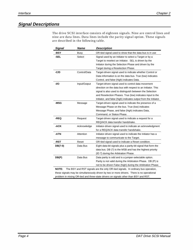
The drive SCSI interface consists of eighteen signals. Nine are control lines andnine are data lines. Data lines include the parity signal option. These signalsare described in the following table.
Signal Name Description
-BSY Busy OR-tied signal used to show that the data bus is in use
-SEL Select Signal used by an Initiator to select a Target or by a
Target to reselect an Initiator. SEL is driven by the
Initiator during the Selection Phase and driven by the
Target during a Reselection Phase.
-C/D Control/Data Target-driven signal used to indicate whether Control or
Data information is on the data bus. True (low) indicates
Control, and false (high) indicates Data.
-I/O Input/Output Target-driven signal used to control data movement
direction on the data bus with respect to an Initiator. This
signal is also used to distinguish between the Selection
and Reselection Phases. True (low) indicates input to the
Initiator, and false (high) indicates output from the Initiator.
-MSG Message Target-driven signal used to indicate the presence of a
Message Phase on the bus. True (low) indicates
Message Phase, and false (high) indicates Data,
Command, or Status Phase.
-REQ Request Target-driven signal used to indicate a request for a
REQ/ACK data transfer handshake.
-ACK Acknowledge Initiator-driven signal used to indicate an acknowledgment
for a REQ/ACK data transfer handshake.
-ATN Attention Initiator-driven signal used to indicate the Initiator has a
message to communicate to the Target.
-RST Reset OR-tied signal used to indicate a Reset condition.
DB(7-0) Data Bus Eight data-bit signals plus a parity-bit signal that form the
data bus. DB (7) is the MSB and has the highest priority
(ID 7) during the Arbitration Phase.
DB(P) Data Bus Data parity is odd and is a jumper-selectable option.
Parity is not valid during the Arbitration Phase. DB (P) is
not to be driven False (high) during the Arbitration Phase.
NOTE: The BSY and RST signals are the only OR-tied signals. In ordinary bus operation,
these signals may be simultaneously driven by two or more drivers. There is no operational
problem in mixing OR-tied and three-state drivers on signals other than BSY and RST.

Interface Chapter 2
DAT Drive SCSI Manual Page 5
Command Set Description
The following table shows the SCSI-1 X3.131 commands for sequential accessdevices implemented by the DAT drive.
Code Type Command
00h O TEST UNIT READY01h M REWIND02h V REQUEST BLOCK ADDRESS03h M REQUEST SENSE05h E READ BLOCK LIMITS08h M READ0Ah M WRITE0Ch V SEEK BLOCK10h M WRITE FILEMARKS11h O SPACE12h E INQUIRY13h O VERIFY15h O MODE SELECT16h O RESERVE UNIT17h O RELEASE UNIT19h O ERASE1Ah O MODE SENSE1Bh O LOAD/UNLOAD1Dh O SEND DIAGNOSTIC1Eh O PREVENT/ALLOW MEDIUM REMOVAL40h * CHANGE DEFINITION
M = Mandatory Command O = Optional Command
V = Vendor Unique Command * = Defined in SCSI-2
E = Required for device-independent self-configuring software

Interface Chapter 2
Page 6 DAT Drive SCSI Manual
The following table shows the SCSI-2 commands for sequential access devicesimplemented by the drive.
Code Type Command Group
00h M TEST UNIT READY 001h M REWIND 002h V REQUEST BLOCK ADDRESS 003h M REQUEST SENSE 005h M READ BLOCK LIMITS 007h A INITIALIZE ELEMENT STATUS 008h M READ 00Ah M WRITE 00Ch V SEEK BLOCK 010h M WRITE FILEMARKS 011h M SPACE 012h M INQUIRY 013h O VERIFY 015h M MODE SELECT 016h M RESERVE UNIT 017h M RELEASE UNIT 019h M ERASE 01Ah M MODE SENSE 01Bh O LOAD/UNLOAD 01CH O RECEIVE DIAGNOSTIC RESULTS 01Dh M SEND DIAGNOSTIC 01Eh O PREVENT/ALLOW MEDIUM REMOVAL 02Bh O LOCATE 134h O READ POSITION 13Bh O WRITE DATA BUFFER 13Ch O READ DATA BUFFER 140h O CHANGE DEFINITION 24Ch O LOG SELECT 24Dh O LOG SENSE 2A5H A MOVE MEDIUM 5A6H A EXCHANGE MEDIUM 5B8H A READ ELEMENT STATUS 5
M = Mandatory Command V = Vendor Unique Command
O = Optional Command A = Autoloader Command Only
Interface Chapter 2
DAT Drive SCSI Manual Page 7
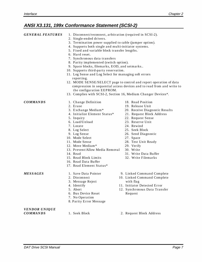
ANSI X3.131, 199x Conformance Statement (SCSI-2)
GENERAL FEATURES 1. Disconnect/reconnect, arbitration (required in SCSI-2). 2. Single-ended drivers. 3. Termination power supplied to cable (jumper option). 4. Supports both single and multi-initiator systems. 5. Fixed and variable block transfer lengths. 6. Hard reset. 7. Synchronous data transfers 8. Parity implemented (switch option). 9. Space blocks, filemarks, EOD, and setmarks..10. Supports third-party reservation.11. Log Sense and Log Select for managing soft errors reporting.12. MODE SENSE/SELECT page to control and report operation of data compression in sequential access devices and to read from and write to the configuration EEPROM.13. Complies with SCSI-2, Section 16, Medium Changer Devices*.
COMMANDS 1. Change Definition 18. Read Position 2. Erase 19. Release Unit 3. Exchange Medium* 20. Receive Diagnostic Results 4. Initialize Element Status* 21. Request Block Address 5. Inquiry 22. Request Sense 6. Load/Unload 23. Reserve Unit 7. Locate 24. Rewind 8. Log Select 25. Seek Block 9. Log Sense 26. Send Diagnostic10. Mode Select 27. Space11. Mode Sense 28. Test Unit Ready12. Move Medium* 29. Verify13. Prevent/Allow Media Removal 30. Write14. Read 31. Write Data Buffer15. Read Block Limits 32. Write Filemarks16. Read Data Buffer17. Read Element Status*
MESSAGES 1. Save Data Pointer 9. Linked Command Complete 2. Disconnect 10. Linked Command Complete 3. Message Reject with flag 4. Identify 11. Initiator Detected Error 5. Abort 12. Synchronous Data Transfer 6. Bus Device Reset Request 7. No Operation 8. Parity Error Message
VENDOR UNIQUECOMMANDS 1. Seek Block 2. Request Block Address

Interface Chapter 2
Page 8 DAT Drive SCSI Manual
SCSI Bus Protocol
Communication on the SCSI bus occurs between a host computer's SCSIcontroller and a peripheral controller. The host controller is the Initiator, andthe peripheral device is the Target.
Some SCSI bus functions are assigned to the Initiator and others to the Target.The Initiator arbitrates (enters the Arbitration Phase of operation) for control ofthe SCSI bus and enters the Selection Phase to select a specific Target such as aDAT drive.
The Target drive can request transfer of command, data, status, information, ordisconnect from the bus. While the DAT drive is disconnected, the bus is free toaccomplish other tasks. While disconnected, the Target drive can processinformation obtained from the bus. If the Target wants to reconnect, itarbitrates for bus control. For example, a Target can reselect an Initiator oranother Target to continue an operation.
At times, the Target actually becomes an Initiator and arbitrates for control ofthe SCSI bus. This situation occurs only during a COPY operation.
Data-transfer operations on the SCSI bus are either asynchronous orsynchronous. Asynchronous data transfer operations follow a definedrequest/acknowledge (REQ/ACK) handshake protocol. One eight-bit byte ofinformation can be transferred with each REQ/ACK handshake. The defaultdata transfer mode is asynchronous.
Synchronous data transfer operations are initiated through theSYNCHRONOUS DATA TRANSFER REQUEST message from the Initiator.
The SCSI bus protocol is divided into three modes or phases of operation:Waiting Phases, Control Phases, and Information Transfer Phases. Thesephases are further subdivided into the eight operational phases as listed in thefollowing table. Information on these operational phases is contained in thefollowing paragraphs.
WaitingPhases
Control Phases Information Phases
1. Bus Free 2. Arbitration 5. Command3. Selection 6. Data (Data In/Data Out)4. Reselection 7. Status
8. Message (Message In/ Message Out)
Waiting and Control Phases
The status of the SCSI bus is a function of the control signals. These signalsdefine the SCSI as in the Waiting Phase (Bus Free Phase), the Control Phases(Arbitration, Selection, or Reselection), or the Information Transfer Phases(Command, Data, Status, or Message). DAT drives support both a SCSI systemwith Arbitration Phase and a SCSI system without Arbitration Phase(nonarbitrating system).

Interface Chapter 2
DAT Drive SCSI Manual Page 9
Nonarbitrating Systems
In systems where the Arbitration Phase is not implemented (SCSI-1 only), theallowable sequences are shown in Figure 2-1. The normal progression is fromthe Bus Free Phase to the Selection Phase and from the Selection Phase to oneor more of the Information Transfer Phases. See the ANSI SCSI X1.31-1986standard for detailed discussions of bus timing.
Figure 2-1Phase Sequencing with Nonarbitration
RESET CONDITION
BUS FREE PHASE
SELECTION PHASE
COMMAND, DATA, STATUS, OR MESSAGE
PHASE
Arbitrating Systems
In arbitration systems (required in SCSI-2), the sequence of SCSI bus phasesfollows the sequence shown in Figure 2-2. Operation begins with the Bus FreePhase. Normal progression is from the Bus Free to the Arbitration Phase.During Arbitration, Initiators and Targets assert for control of the SCSI bus.The bus is awarded to the device with the highest priority SCSI bus address.
Figure 2-2Phase Sequencing with Arbitration
RESET CONDITION
BUS FREE PHASE
ARBITRATION PHASE
SELECTION OR RESELECTION
PHASE
COMMAND, DATA, STATUS, OR MESSAGE
PHASE

Interface Chapter 2
Page 10 DAT Drive SCSI Manual
Arbitration is won by the highest priority SCSI device when both BSY and SELare asserted and a delay of at least 1200 nSec (1 bus clear delay + 1 bus settledelay) occurs before the Arbitration Phase ends and the Selection Phase begins.Signal timing is shown in Figure 2-3 and the complete Arbitration Phaseprotocol is described in the following table.
Figure 2-3Arbitration and Selection Phase Signal Timing
SIGNALS
(Busy) BSY
(Select) SEL
(Data) DB(7-O,P) BUS FREE
PHASE
ARBITRATION ID's
ARBITRATION PHASE
SELECTION PHASE
INITIATOR ID & TARGET ID
Step Procedure
1. The SCSI device first waits for a Bus Free Phase to occur. The Bus Free Phase is detected when
both the BSY and SEL signals are simultaneously and continuously false for a minimum of a bus
settle delay of 400 nSec.
2. The SCSI device waits a minimum of one bus free delay of 800 nSec after detection of a Bus Free
Phase before driving any signal. The Bus Free Phase occurs after BSY and SEL are both false for
a bus settle delay of 400 nSec.
3. Following the 800 nSec Bus Free Delay in Step 2, the SCSI device Arbitrates for the SCSI bus by
asserting both BSY and its own SCSI ID; however, the SCSI device does not assert a BSY and its
SCSI ID if more than a bus settle delay (1.8 Sec) has passed since the Bus Free Phase was last
observed.
4. After waiting at least an Arbitration delay (2.2 Sec) measured after asserting a BSY signal, the
SCSI device examines the data bus. If a higher priority SCSI ID bit is true, then the SCSI device
loses the Arbitration. The SCSI device releases its signals and returns to Step 1. If no higher
priority SCSI ID bit is true on the bus, then the SCSI drive wins the Arbitration and asserts the SEL
signal. Any other device that participated in the Arbitration Phase and lost Arbitration releases BSY
and its SCSI ID bit within a bus clear delay after SEL becomes true. A SCSI device that loses
Arbitration returns to Step 1.
5. The SCSI device that wins Arbitration waits at least one bus clear delay plus a bus settle delay of
1,200 nSec after asserting the SEL signal and changing the condition of other signals.
NOTE: The single SCSI ID bit on the data bus corresponds to the unique ID code of the SCSI device. All other
SCSI data bus bits are released by the SCSI device. Parity is not valid during the Arbitration Phase. During the
Arbitration Phase, DB(P) may be undriven or driven true, but not false.

Interface Chapter 2
DAT Drive SCSI Manual Page 11
Selection and Reselection Phases
The Selection and Reselection Phases provide a method for establishing a linkbetween the Initiator and Target. When selected by an Initiator that supportsdisconnects, the Target has the option of disconnecting from the SCSI bus.When the Target needs to again establish the link to its original Initiator, theTarget reselects that Initiator.
When selection is made, no restrictions on the sequences between InformationTransfer Phases exist. A phase type may be followed by the same phase type.For example, a data phase may be followed by another data phase.
A device that wins Arbitration assumes the roll of Initiator by releasing the I/Osignal. The Initiator sets the data bus to a value that is the OR of its SCSI IDbit and the Targets ID bit. The Initiator waits at least two deskew delays (90nSec) before releasing the BSY signal and an additional bus settle delay (400nSec) before looking for a response from the Target.
A device that loses Arbitration must release the Select ID and BSY.
Operation enters the Selection or Reselection Phases when a particular devicewins a request in Arbitration and gains control of the SCSI bus. These phasesallow the device in control of the bus to select another specific device connectedto the SCSI bus for communication.
For example, the Initiator can select a DAT drive to begin an operation, or theDAT drive can reselect an Initiator to continue an operation previouslydisconnected. The DAT drive does not disconnect from the bus unless the hostasserted the host ID bit during selection and the host sent an Identify messageof C0h.
The Selection and Reselection Phases can be terminated for either of thefollowing reasons:
l A Selection/Reselection time-out occurs. A Target or Initiator did notrespond to a Selection or Reselection Phase within a maximum abort timeof 200 Sec.
l A reset signal occurs on the SCSI bus. All sequences are terminated, andsignals are released by all Targets and Initiators.
The Initiator can use the ATN signal to notify the DAT drive that anIDENTIFY message from the Initiator is ready. To ensure that the Targetrecognizes the Attention condition before the Command Phase is entered, theATN signal must be low before SEL is asserted and BSY deasserted.
Select With Attention
The host system can select the DAT drive in one of two ways: a simple Select ora Select With Attention. The Select With Attention allows the host to send theIdentify message to specify that the host supports disconnects.

Interface Chapter 2
Page 12 DAT Drive SCSI Manual
The host can also use the Select With Attention to send messages other thanthe Identify message. For example, a Bus Device Reset or Abort message can besent to cause the drive to reset itself without affecting any other device on theSCSI bus. The DAT drive responds appropriately to the host messages.
If the DAT drive receives an illegal message, it enters the Message Out Phaseand sends the Reject message to the host. If any reserved bit (bits 5, 4, or 3) isset, an Identify message is rejected.
Responses to Identify messages with a non-zero LUN are described in thefollowing subsection.
Identify Message
Because the DAT drive only supports Logical Unit 0, the Identify message isused solely to specify the Disconnect option. The bit map for the Identifymessage is as follows:
Bits 7 6 5 4 3 2 1 0
I DIS | RESERVED | LUN
If bit 7 is set, the Identify message is indicated. Bit 6 (shown as DIS) is set asfollows:
0 The host does not support disconnects. The DAT drive does not disconnectfrom the SCSI bus during the current command.
1 The host supports disconnects. The DAT drive disconnects from the SCSIbus appropriately for the command in progress to relinquish the bus forother units.
LUN = 1 is legal for Autoloader drives only.
Information Transfer Phases
The Command, Data, Status, and Message Phases are grouped together as theInformation Transfer Phases because they are all used to transfer data orcontrol information on the SCSI bus.
The following table shows the Control Data (C/D), Input/Output (I/O), andMessage (MSG) signals used to distinguish between the various InformationTransfer Phases. The Target drives these three signals and thereby controls allchanges from one phase to another.

Interface Chapter 2
DAT Drive SCSI Manual Page 13
Signals -MSG -C/D -I/O Phases Direction of Transfer
-I/O 1 1 1 Data Initiator to Target
1 1 0 Data Target to Initiator
-C/D 1 0 1 Command Initiator to Target
1 0 0 Status Target to Initiator
-MSG 0 0 1 Message Initiator to Target
0 0 0 Message Target to Initiator
Key: 1 = False, 0 = True
Information Transfer Phases use one or more REQ/ACK handshakes to controlthe information transfer. Each REQ/ACK handshake allows the transfer of onebyte of information. During the information transfer phases, BSY remains trueand SEL remains false. C/D, I/O, and MSG control signals are valid for a bussettle delay of 400 nSec before assertion of REQ signal at the first handshakeand remain valid until negation of ACK at the end of the last handshake.
Asynchronous Data Transfer
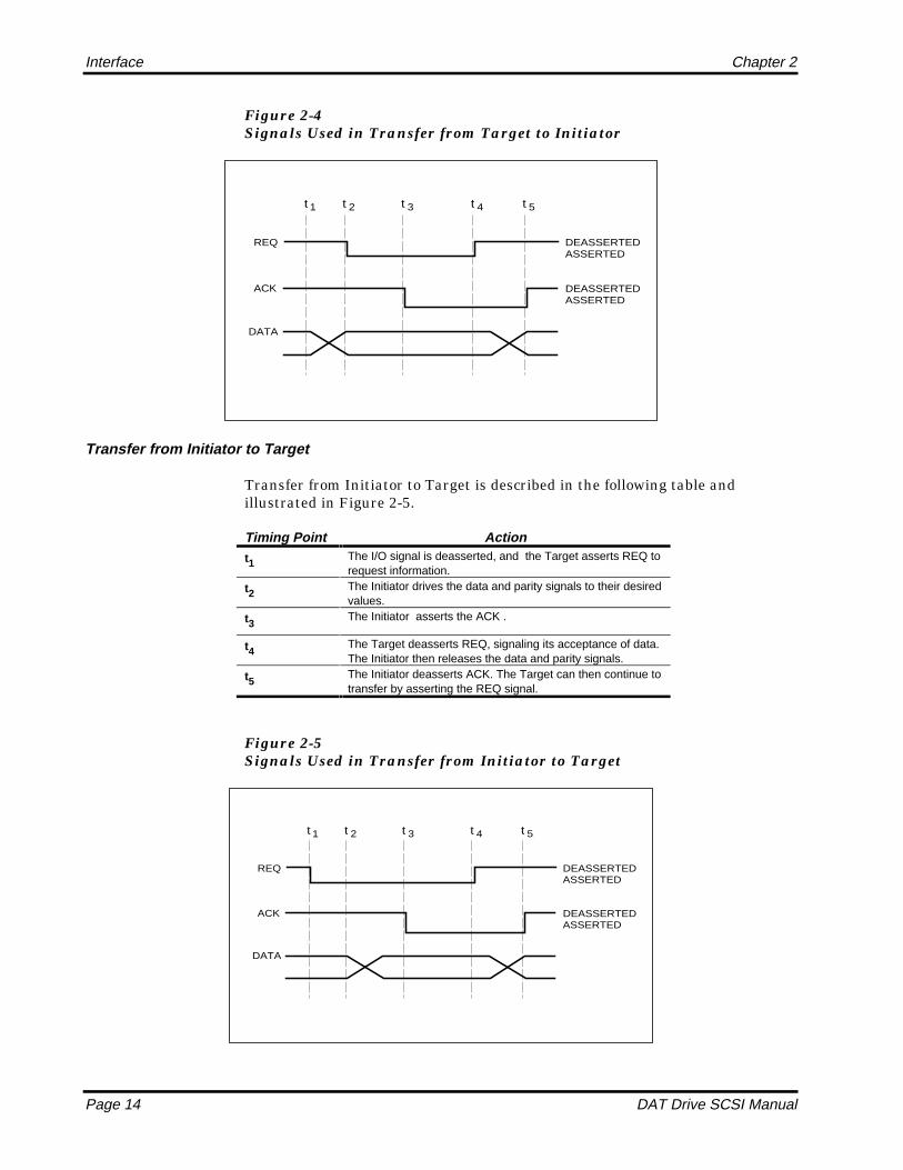
The Target controls the direction of information transfer with the I/O signal.When I/O is asserted (low), information is transferred from the Target to theInitiator. When I/O is deasserted (high), information is transferred from theInitiator to the Target. Figure -4 shows the data transfer signals for informationtransfer from Target to Initiator, and Figure 2-5 shows the data transfer signalsfor information transfer from Initiator to Target. Each direction of informationtransfer is discussed in detail in the following paragraphs.
Transfer from Target to Initiator
The transfer from Target to Initiator is described in the following table andillustrated in Figure 2-4.
Timing Point Actiont1 The I/O signal is asserted; the Target drives the data (DB7-0)
and parity signals to their desired values.
t2 The Target then asserts the REQ signal.
t3 The Initiator reads the data and parity signals after REQ isasserted and then signals its acceptance of the data byasserting the ACK.
t4 ACK goes low at the Target, and the Target deasserts REQ.
t5 The REQ signal is false. The Initiator deasserts ACK. Afterthe ACK signal is high, the Target can continue the transferby repeating the steps from t1.
Interface Chapter 2
Page 14 DAT Drive SCSI Manual
Figure 2-4Signals Used in Transfer from Target to Initiator
t 1 t
2 t
3 t
4 t
5
REQ
ACK
DATA
DEASSERTED ASSERTED
DEASSERTED ASSERTED
Transfer from Initiator to Target
Transfer from Initiator to Target is described in the following table andillustrated in Figure 2-5.
Timing Point Actiont1 The I/O signal is deasserted, and the Target asserts REQ to
request information.
t2 The Initiator drives the data and parity signals to their desiredvalues.
t3 The Initiator asserts the ACK .
t4 The Target deasserts REQ, signaling its acceptance of data.The Initiator then releases the data and parity signals.
t5 The Initiator deasserts ACK. The Target can then continue totransfer by asserting the REQ signal.
Figure 2-5Signals Used in Transfer from Initiator to Target
t 1 t
2 t
3 t
4 t
5
REQ
ACK
DATA
DEASSERTED ASSERTED
DEASSERTED ASSERTED

Interface Chapter 2
DAT Drive SCSI Manual Page 15
Synchronous Data Transfer
Both the Initiator and Target must send a SYNCHRONOUS DATA TRANSFERREQUEST (SDTR) message in order to set up synchronous data transferparameters. The SDTR is the only extended (multibyte) message supported. Thehost may initiate an SDTR to establish a new synchronous data transferagreement or to end a previously arranged synchronous data transferagreement and return to asynchronous data transfer mode.
The following table shows the format for the SDTR message.
Byte Value Description
0 01h Extended message1 03h Extended message length2 01h Synchronous Data Transfer Request Code3 m* Transfer Period (m x 4 nsec)4 ** REQ/ACK Offset* Transfer Period can be any value between 32h and 15Eh.** REQ/ACK Offset can be any value between 0 and Fh.
The Transfer Period is the minimum time allowed between leading edges ofsuccessive REQ pulses and of successive ACK pulses to meet the requirementsof the DAT drive for successful reception of data. The host and DAT drive cantransfer data with larger, but never smaller, Transfer Period than specified inthe SDTR message.
The minimum value of the Transfer Period (200 nSec) is determined by themaximum burst transfer rate of the SCSI interface hardware of the DAT driveand is 5 MB/sec (32h). The host must specify a Transfer Period that allows it tosuccessfully receive data from the DAT drive during the Data In Phase.Transfer Period represents the actual transfer period, in nanoseconds, dividedby 4.
The REQ/ACK Offset is the maximum number of pulses that can be sent by theDAT drive in advance of the number of ACK pulses received from the host,establishing a pacing mechanism. If the number of REQ pulses is greater thanthe number of ACK pulses by the REQ/ACK Offset, the DAT drive stopssending data until after the leading edge of the next ACK is received.
The ACK/REQ Offset is used to prevent an overflow condition in the host'sreception buffer during the Data In Phase. The REQ/ACK Offset should be setto the size of the host's reception buffer minus one.
To set up a new synchronous data transfer agreement, the host asserts the ATNsignal and sends an SDTR message. The Transfer Period must be set to a valueequal to or greater than 32h and less than the maximum rate of the host'sreception buffer. The ACK/REQ Offset will be set to a nonzero value between 1and the size of the host's reception buffer minus 1, but it should not exceed 0Fh.
If the Transfer Period and the ACK/REQ Offset are within the ranges describedabove, the DAT drive goes to the Message In Phase and returns an SDTRmessage with the same Transfer Period and ACK/REQ Offset. This return
Interface Chapter 2
Page 16 DAT Drive SCSI Manual
indicates a successful completion of the SDTR message exchange. The impliedsynchronous data transfer agreement remains in effect until:
l A Bus Device Reset message is received.
l A hard reset condition occurs.
l The successful completion of the next SDTR message exchange.
If the Transfer Period is less than 32h and/or the REQ/ACK Offset is greaterthan 0Fh, the DAT drive returns an SDTR message with its maximum values—32h for Transfer period and/or 0Fh for REQ/ACK offset. Both the host and theDAT drive then go to the synchronous data transfer mode for data transfersbetween them.
If the host specifies a REQ/ACK offset of zero, the DAT drive operates in theasynchronous data transfer mode.
Command Phase
During the Command Phase, the Target requests command information fromthe Initiator. The Target asserts the C/D signal and deasserts the I/O and MSGsignals thus denoting the Command Phase. The REQ/ACK then handshakes thecommand bytes across the SCSI bus (Figure 2-5). The command bytes are alsocalled the Command Descriptor Block (CDB).
Data Phase
The Data Phase is subdivided into the Data-In and Data-Out Phases.
Data-In Phase
During the Data-In phase, the Target requests that data be sent to the Initiatorfrom the Target. The Target asserts the I/O signal and deasserts the C/D andMSG signals thus denoting the Data-In Phase. The REQ/ACK handshakes(Figure 2-4) then transfer the requested byte count.
Data-Out Phase
During a Data-Out phase, the Target requests that data be sent from theInitiator to the Target. The Target deasserts the C/D, I/O, and MSG signalsthus denoting the Data-Out Phase. The REQ/ACK handshakes (Figure 2-5)then transfer the requested byte count across the SCSI bus.
Status Phase
During a Status Phase, the Target requests that status information be sent tothe Initiator from the Target. The Target asserts the C/D and I/O signals anddeasserts the MSG signal thus denoting the Status Phase. The REQ/ACKhandshakes the one byte status code across the SCSI bus (refer to Figure 2-4).

Interface Chapter 2
DAT Drive SCSI Manual Page 17
Message Phase
The Message Phase consists of either the Message-In or Message-Out Phases.The DAT drive supports one-byte messages.
Message-In Phase
During the Message-In Phase, the Target requests that messages be sent to theInitiator from the Target. The Target asserts the C/D, I/O, MSG signals thusdenoting the Message-In Phase. The REQ/ACK handshakes the one-bytemessage across the SCSI bus.
Message-Out Phase
During the Message-Out Phase, the Target requests that messages be sent fromthe Initiator to the Target. The Target invokes this phase in response to theAttention (ATTN) signal asserted by the Initiator. The DAT drive responds tothe ATTN signal at every phase change. The Target asserts the C/D and MSGsignals and deasserts the I/O signal, denoting the Message-Out Phase. TheREQ/ACK handshakes the one byte message across the SCSI bus. The Targetuses REQ/ACK handshakes (Figure 2-5) until the ATN signal becomes false,unless an error occurs and the message is rejected.
Command Descriptor Block
A request to a peripheral device is performed by sending a Command DescriptorBlock (CDB) to the Target. For several commands, the request is accompaniedby a list of parameters sent during a Data Out Phase. If an invalid parameter iscontained in the CDB, the DAT drive terminates the command without alteringthe medium.
The DAT implementation supports Group 0 and selected Group 1 and Group 2commands. Group 0 CDBs are six-bytes; Group 1 and 2 CDBs are ten-bytes.
The CDB contains both reserved bit fields and defined bit fields. Defined bitfields are: Group Code, Command Code, Logical Unit Number (LUN), VendorUnique (VU), Flag, and Link, whereas reserved bit fields are defined by zerossuch as those appearing on the last line of the following table. This table showsa typical Group 0, six-byte, Command Descriptor Block.

Interface Chapter 2
Page 18 DAT Drive SCSI Manual
ByteBits
7 6 5 4 3 2 1 0
0 Group Code Command Code
1 LUN Command Dependent
2 Command Dependent
3 Command Dependent
4 Command Dependent
5 VU VU 0 0 0 0 Flag Link
The following table shows a typical Command Descriptor Block for Group 1 and2 commands.
ByteBits
7 6 5 4 3 2 1 0
0 Group Code Command Code
1 LUN Command Dependent
2 Command Dependent
3 Command Dependent
4 Command Dependent
5 Command Dependent
6 Command Dependent
7 Command Dependent
8 Command Dependent
9 VU VU 0 0 0 0 Flag Link
The following table describes the CDB fields common to all Group 0, 1, and 2commands.
CDB Field Description
Group Code* This field indicates which of eight possible SCSI command groups is specified. DAT drives support
Group 0.
Command Code* This field indicates which of 32 possible command codes for a particular group code is specified.
Logical Unit The LUN must be set to zero.
Vendor Unique When set, these bits select vendor unique functions in specified commands.
Flag bit The Flag bit is used only in conjunction with the Link bit and must be set to zero if the Link bit is zero.
When the Link bit is set, the value of the Flag bit determines the appropriate message to send to the
Initiator when a linked command completes successfully. A 0 value indicates that the Linked
Command Complete message is required. A 1 value indicates that the Linked Command Complete
with Flag message is required. Typically, the Flag bit is used to cause an interrupt in the Initiator at
the end of, or at logical intervals in, linked command processing.
Link bit** The Link bit is used to indicate that the Initiator desires automatic linking to the next command on
successful completion of the current command. When the Link bit is one, on successful termination of
the command, the drive returns an Intermediate Status followed by one of the two Command
Complete messages as determined by the Flag bit. (Refer to description of Flag bit above.)
* Together, group code and command code make up the op code.
** If the Link bit is used, all applicable commands must have the Immed bit set to zero or a Check Condition status is
returned and Extended Sense Key is set to Illegal Request.

Interface Chapter 2
DAT Drive SCSI Manual Page 19
Logical Unit Support
The DAT drive only supports Logical Unit (LUN) 0, except for the Autoloader,which supports both LUN 0 and LUN 1. However, it responds to a hostcommand that tries to select or identify any other LUN. The response of thedrive to illegal LUNs varies depending on the command and the manner inwhich the host specifies the LUN.
The host can specify an LUN in one of two ways:
l By sending an Identify message after the Selection Phase
l By specifying the LUN in byte 1 of the CDB (host did not send an Identify message)
Because of the redundancy of specifying the LUN, the DAT drive respondsappropriately if the LUN is specified in both the Identify message and in theCDB. If the drive is selected and a valid Identify message is received withLUN = 0 (or LUN = 1 if the drive is an Autoloader), the LUN field of the CDB isignored. Thus, the Identify message overrides the CDB LUN specification.
Because the SCSI INQUIRY command determines what LUNs a particularSCSI device supports, the response from the drive to this command is unique.With the INQUIRY command when the drive receives an unsupported LUN,the command completes normally. The drive indicates that it does not supportthe specified LUN by returning a 7F hexadecimal value in byte 0 of theINQUIRY data. Regardless of what method is used to specify the LUN, the 7Fhex value is returned.
If an unsupported LUN is specified for a REQUEST SENSE command, thecommand completes normally with Good Status, and the sense data is set toIllegal Request.
For all other commands, the illegal LUN is detected in both the Identifymessage out and CDB methods, as follows:
l If an illegal LUN is specified in the Identify message, the drive enters theCommand Phase and accepts the CDB. It immediately skips to the StatusPhase and posts a Check Condition. The Sense data is set to IllegalRequest. If the Identify message is correct, the CDB LUN is ignored.
l If the DAT drive is selected without Attention (no Identify message sent),then the CDB LUN must be 0. In that case if an illegal LUN is specified inthe CDB, the drive skips to the Status Phase and posts a Check Condition.The Sense data is set to Illegal Request.

Interface Chapter 2
Page 20 DAT Drive SCSI Manual
SCSI Message Descriptions and Definitions
The SCSI message codes, descriptions, and directions are given in the followingtable. Each of these SCSI messages are supported by the DAT drive.
þ Note: If a message parity error is detected, the drive terminates the I/Oprocess and goes bus free.
Code Description Direction*
00h Command Complete In
02h Save Data Pointer In
04h Disconnect In
05h Initiator Detected Error Out
06h Abort Out
07h Message Reject In/Out
08h No Operation Out
0Ah Linked Command Complete In
0Bh Linked Command Complete with Flag In
0Ch Bus Device Reset Out
80h Identify (when sent by host, disables Disconnect/Reconnect) In/Out
C0h Identify (enable Disconnect/Reconnect) Out
01h** Extended Message In/Out
* Direction: In = Drive to host; Out = Host to drive.
** Supports only one extended message: Synchronous Data Transfer Request.
The following table provides the SCSI message definitions.

Interface Chapter 2
DAT Drive SCSI Manual Page 21
HexCode Message Definition
00h Command
Complete
This message is sent from the DAT drive to inform an Initiator
that execution of a command terminated and that valid status
was sent to the Initiator. After successfully sending this
message, the drive goes to the Bus Free Phase by releasing
BSY.
NOTE: The command may have been executed successfully or
unsuccessfully as indicated in the status.
02h Save Data
Pointer
This message is sent from the DAT drive to direct the Initiator to
save a copy of the present active data pointer for the DAT drive.
03h Restore Data
Pointer
Never sent by the drive.
04h Disconnect This message is sent from the DAT drive to inform an Initiator
that the present physical path is going to be broken (DAT drive
plans to disconnect by releasing BSY) and, a later reconnect is
required to complete the current operation. If the Initiator detects
the Bus Free Phase, other than as the result of a Reset
condition, without first receiving a Disconnect or Command
Complete message, the Initiator considers this as a catastrophic
error condition. The Disconnect message does not cause the
Initiator to save the data pointer. If Disconnect messages are
used to break a long data transfer into two or more shorter
transfers, then a Save Data Pointer message is issued by the
DAT drive before each Disconnect.
05h Initiator
Detected Error
This message is sent from an Initiator to inform the DAT drive
that an error, such as a parity error, occurred.
06h Abort This message is sent from an Initiator to clear the present drive
operation. All pending data and status for the issuing Initiator are
cleared, and the drive goes back to Bus Free Phase. No status
or ending message is sent for the operation. Any previously set
modes are not changed.
07h Message
Reject
This message is sent from the DAT drive to indicate the last
message it received was inappropriate or was not implemented.
The DAT drive sends Message Reject and then goes to the
Message-In phase prior to requesting additional message bytes
from the Initiator. This sequence provides an interlock so the
Initiator can determine which message was rejected.
08h No Operation This message is sent from an Initiator in response to a DAT
drive request for a message, when the Initiator does not
currently have any other valid message to send.
09h Parity Error This message is sent from the host to indicate that incorrect
parity was detected. See the following table.
0Ah Linked
Command
Complete
This message is sent from the DAT drive to inform an Initiator
that execution of a linked command is completed and that status
was sent. The Initiator can then set the pointers to the initial state
for the next linked command.

Interface Chapter 2
Page 22 DAT Drive SCSI Manual
HexCode Message Definition
0Bh Linked
Command
complete with
Flag
This message is sent from the DAT drive to inform an Initiator
that execution of a linked command with the Flag bit set to one,
is completed and that status was sent. The Initiator then sets the
current pointers to the initial state of the next linked command.
Typically, this message is used to cause an interrupt in the
Initiator between two linked commands.
0Ch Bus Device
Reset
This message is sent from an Initiator to direct the drive to clear
all current commands; it forces the drive to an initial state with no
operations pending for any Initiator. On recognizing this
message, the drive moves to the Bus Free Phase. All modes are
reset to the default state.
Identify
(80h disable
Disconnect/
Reconnect)
(C0h enable
Disconnect/
Reconnect)
These messages are sent by either the Initiator or DAT drive to
establish the physical path between them. The physical path
connection indicates that both the Initiator and DAT drive have
message passing capability. Bit 7 is set to one to distinguish
these messages from other messages. Bit 6 is set to one by the
Initiator indicating the Initiator has the ability to accommodate
disconnection and reconnection. Bits 5 through 3 are reserved
(set to zero). Bits 2 through 0 specify the logical unit number that
must be 0 for the DAT drive. When Identify is sent from the drive
to an Initiator during reconnection, an implied Restore Pointers
message is performed by the Initiator prior to completion of this
message.
The following table describes the operation for each of the possible cases ofparity error.
State or Phase Description
Bus Free State The drive does not detect nor react to parity errors on the SCSI bus while thedrive is in a bus free state.
Arbitration Phase The drive does not detect nor react to parity errors on the SCSI bus whilearbitration is being performed.
Selection Phase The drive does not detect nor react to parity errors on the SCSI bus while thedrive is being selected.
Selection, Message Out Phase(Identify Message)
If the drive detects a parity error while the host is sending an Identify message,the drive goes to Bus Free.
Reselection, Message In Phase(Identify Message)
If the drive is attempting to reconnect to the host and the host asserts ATNbecause it detected an error, the drive• Switches the host to the Message Out Phase.• Waits for the host to send a 09 (Parity Error Message)The drive then performs the retry option by:• Switching the host to the Message In Phase.• Resending the Identify Message
Command Phase If the drive detects a parity error while the host is transferring a CDB, the drive• Terminates the transfer.• Switches the host to the Status Phase and sends a Check Condition.• Switches the host to the Message In Phase and sends a Command
Complete.• Sets the Sense Key = B and ASC/ASCQ = 47-00 (SCSI-2 only).

Interface Chapter 2
DAT Drive SCSI Manual Page 23
State or Phase Description
Data In Phase If the host detects a parity error while data is being transferred from the drive andasserts ATN, the drive• Terminates the transfer of data.• Switches the host to the Message In Phase and sends a 02 (Save Data
Pointer).• Switches the host to the Message Out Phase.• Waits for the host to send an 05 (Host Detected Error).• Switches the host to the Status Phase and sends a Check Condition.• Switches the host to the Message In Phase and sends a Command Complete.• Sets the Sense Key = B and ASC/ASCQ = 48-00 (SCSI-2 only).
Data Out Phase If the drive detects a parity error while the host is transferring data, the drive• Terminates the transfer of data.• Switches the host to the Status Phase and sends a Check Condition.• Switches the host to the Message In Phase and sends Command Complete.• Sets the Sense Key = B and ASC/ASCQ = 47-00 (SCSI-2 only).
Status Phase If the host is in the Status phase and detects an error in the status byte and assertsATN, the drive• Switches the host to the Message Out Phase and waits for the host to send 05
(Initiator Detected Error).• Switches the host to the Status Phase and sends a Check Condition.• Sets the Sense Key = B and ASC/ASCQ = 48-00 (SCSI-2 only).
Message In Phase If the host is in the Message In Phase and detects an error on a message bytes anasserts ATN, the drive• Switches the host to the Message Out Phase.• Waits for the host to send 09 (Parity Error Message).• Switches the host to the Message In Phase and resends the message.
Message In Phase (CommandComplete message)
If the host is in the Message In Phase and detects an error on the commandcomplete message byte and asserts ATN, the drive goes to Bus Free.
Message Out Phase If the host is in the Message Out Phase and sends a message bytes and the drivedetects a parity error, the drive• Switches the host to the Status Phase and sends a Check Condition.• Switches the host to the Message In Phase and sends a Command Complete.• Sets the Sense Key = B and ASC/ASCQ = 47-00 (SCSI-2 only).
An Initiator that accommodates disconnect/reconnect can indicate thiscapability to the DAT drive during the Selection phase by asserting both its ownInitiator SCSI ID bit as well as the DAT SCSI ID bit (allows the DAT drive toknow with which Initiator to reconnect). The Initiator must also assert ATNbefore exiting the Selection phase (prior to releasing SEL) and send an Identifymessage out of C0h to the DAT drive. This sequence causes the drive to enterthe Message-Out phase when the Selection phase completes.
The first message sent by the host after the Selection phase is an Identifymessage. Under normal conditions, the first message sent by the DAT driveafter a Reselection phase is also Identify. Under certain exceptional conditions,the host may send the Abort message or the Bus Device Reset message insteadof Identify as the first message.
Interface Chapter 2
Page 24 DAT Drive SCSI Manual
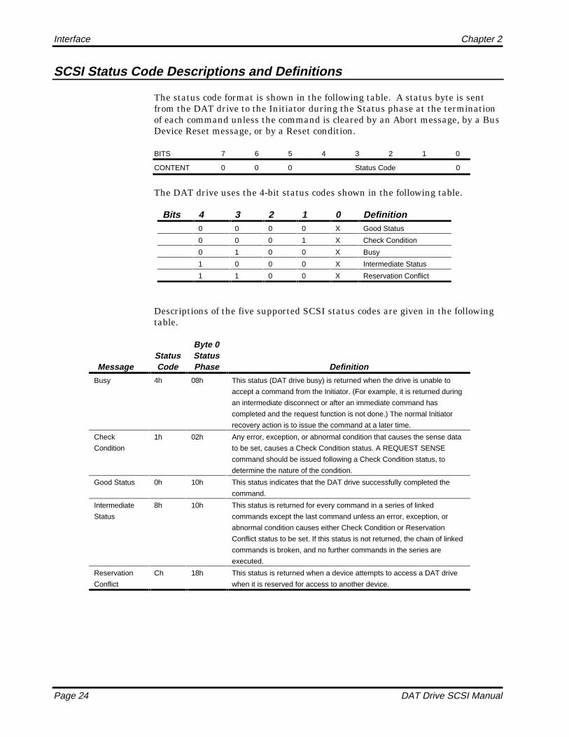
SCSI Status Code Descriptions and Definitions
The status code format is shown in the following table. A status byte is sentfrom the DAT drive to the Initiator during the Status phase at the terminationof each command unless the command is cleared by an Abort message, by a BusDevice Reset message, or by a Reset condition.
BITS 7 6 5 4 3 2 1 0
CONTENT 0 0 0 Status Code 0
The DAT drive uses the 4-bit status codes shown in the following table.
Bits 4 3 2 1 0 Definition0 0 0 0 X Good Status
0 0 0 1 X Check Condition
0 1 0 0 X Busy
1 0 0 0 X Intermediate Status
1 1 0 0 X Reservation Conflict
Descriptions of the five supported SCSI status codes are given in the followingtable.
MessageStatusCode
Byte 0StatusPhase Definition
Busy 4h 08h This status (DAT drive busy) is returned when the drive is unable to
accept a command from the Initiator. (For example, it is returned during
an intermediate disconnect or after an immediate command has
completed and the request function is not done.) The normal Initiator
recovery action is to issue the command at a later time.
Check
Condition
1h 02h Any error, exception, or abnormal condition that causes the sense data
to be set, causes a Check Condition status. A REQUEST SENSE
command should be issued following a Check Condition status, to
determine the nature of the condition.
Good Status 0h 10h This status indicates that the DAT drive successfully completed the
command.
Intermediate
Status
8h 10h This status is returned for every command in a series of linked
commands except the last command unless an error, exception, or
abnormal condition causes either Check Condition or Reservation
Conflict status to be set. If this status is not returned, the chain of linked
commands is broken, and no further commands in the series are
executed.
Reservation
Conflict
Ch 18h This status is returned when a device attempts to access a DAT drive
when it is reserved for access to another device.
Interface Chapter 2
DAT Drive SCSI Manual Page 25
Attention Condition
The Attention Condition allows an Initiator to inform a Target that the Initiatorhas a message to send. The DAT drive may read this message at its convenienceby performing a Message-Out phase. The Initiator creates the AttentionCondition by asserting the ATN signal at any time except during theArbitration or Bus Free phases. The DAT drive checks to see if ATN is set atevery phase change. If ATN is set, the drive goes into the Message-Out phase.The Initiator may deassert the ATN signal at any time. Normally, the Initiatordeasserts ATN during or before the last REQ/ACK handshake of the Message-Out phase. The Attention signal must be present prior to a phase change toallow the DAT drive time to respond with a Message-Out phase at the phasechange.
Reset Condition
The Reset Condition takes precedence over all phases and conditions and isused to immediately terminate operation and clear all SCSI devices from thebus. Any SCSI device can create a reset condition by asserting a RST signal fora minimum reset hold time of 25 microseconds. The DAT drive never assertsreset. During the Reset Condition, all SCSI devices release all SCSI signals(except RST) within a Clear Reset Delay (800 nSec) of the transition of RST tolow. The Bus Free phase always follows the Reset Condition.
When a reset is issued to the DAT drive, the SCSI bus clears all uncompletedcommands, releases all SCSI device reservations, sets the DAT drive to defaultmodes, and returns to the Bus Free phase.
Unit Attention Condition
The Unit Attention condition in the DAT drive typically results from thefollowing conditions:
l A Reset was previously issued to the DAT drive.
l The DAT drive has just been powered on.
l The cartridge was removed when the tape is positioned away from BOT.
l The cartridge was removed when the tape is positioned at BOT following aLOAD command.
l A cartridge has been inserted since the previous bus reset or power-on.
l A log exception condition occurred.
The Unit Attention Condition persists for each Initiator until that Initiatorissues a command other than Inquiry for which the DAT drive returns with aCheck Condition Status. If the next command from that Initiator following theCheck Condition Status is Request Sense, then the unit attention sense key isreturned.
Interface Chapter 2
Page 26 DAT Drive SCSI Manual
If the Inquiry Command is received from an Initiator with a pending UnitAttention Condition before the DAT drive reports Check Condition Status, theDAT drive performs the Inquiry Command and does not clear the UnitAttention Condition.
If the Request Sense Command is received from an Initiator with a pendingUnit Attention Condition before the DAT drive reports Check Condition Status,the DAT drive reports unit attention sense key and clears the Unit AttentionCondition for that Initiator.
Buffered Mode
Buffered Mode allows the most efficient operation of the DAT drive. the drivedefaults to Buffered mode. In this mode, the drive signals Command Completewhen all requested data for a WRITE command has been transferred from thehost to the DAT buffer. This mode provides data to maintain operation whilethe host readies a new WRITE Command.
If an error occurs in writing data to the tape after the DAT drive signalsCommand Complete, an error status is sent on the next Command issued.
Immediate Function
For Initiators that do not support the disconnect feature, the Immediate bitprovides a means of releasing the bus while the drive is busy completing afunction such as repositioning the tape. If a command is sent by the Initiatorafter a previous Immediate Command was accepted, the drive continues theImmediate Function it is currently performing and returns a Busy Status forthe new command.
An immediate bit of zero means that the status is returned to the Initiator whenthe operation is completed. (For example, the status is returned when the tapehas been repositioned.) An Immediate bit of one means that the status isreturned to the Initiator as soon as the function is started.
Residual Length Function
When performing a WRITE command, the drive returns a Good Status andCommand Completion Message when the last byte requested by the command isplaced in the Data Buffer, rather than when it is written onto tape. If an erroroccurs while data is being written onto tape, the drive calculates the ResidualLength and places this value in the information bytes of the Sense Data Block.Also, the Residual Length functions for other commands, such as READ andSPACE.

Interface Chapter 2
DAT Drive SCSI Manual Page 27
Residual Length is calculated by: RL = TL - AL
Where :
AL (Actual Length) = Blocks transferred from the host to the DAT driveacross the SCSI bus.
TL (Transfer Length) = The Transfer Length from bytes 2-4 of the WRITEcommand (Request Transfer Length).
RL (Residual Length) = The amount of blocks or bytes not written to tape.
Disconnect/Reconnect Function
When the drive is performing a task not requiring communication with theInitiator or when the DAT drive determines that a relatively long time haspassed with no bus activity, it disconnects from the SCSI bus. Examples are:
l When rewinding the tape.
l When writing to the tape and the buffer is full.
l When reading from the tape and the buffer is empty.
l When spacing, locating, or generally performing any tape motion whendata cannot be transferred on the SCSI bus.
During the time the Target is disconnected for one of these functions, the bus isfree for use by other devices. Both disconnect and reconnect are initiated by theTarget.
When the Initiator first selects the drive, it sends an Identify Messageindicating that it is allowing the drive to disconnect and reconnect and to becapable of supporting messages other than Command Complete (and the hostset its own ID during selection). To disconnect from the bus, the DAT driveperforms the following procedure:
1. The drive can send a Save Data Pointers Message if the disconnectionfunction was a data transfer.
2. The drive sends a Disconnect Message indicating it is going to disconnect.
3. The drive disconnects from the bus by deasserting BSY and releasingcontrol of all bus signals.
The bus is now free for an Initiator to select any device on the bus, includingthe drive that initiated the disconnect. The drive will respond to selection byanother Initiator.

Interface Chapter 2
Page 28 DAT Drive SCSI Manual
If the DAT drive is selected while disconnected, it only allows the followingactions:
l If the command is from a different initiator or is from the same initiator butto a different LUN, the DAT drive accepts the command and immediatelyreturns Busy Status.
l Immediately following the selection, the Initiator may send the Identify, No Op,Abort, or Bus Device Reset messages to the drive.
l If the command is from the same initiator to the same LUN, the currentcommand terminates with a Check Condition and an Abort Sense Key.
When the disconnected drive is ready to reconnect with the Initiator, it does thefollowing.
1. It monitors the bus waiting for a Bus Free Phase to occur. When a Bus FreePhase is sensed, the DAT drive arbitrates for the bus.
2. If it wins arbitration, the DAT drive then attempts to reselect the Initiator.If the Initiator fails to respond in 250 mSec, the drive drops all bus signalsand allows the bus to again enter the Bus Free Phase. The drive thenrepeats the attempted Arbitration.
3. When the DAT drive has successfully reselected the Initiator, it sends anIdentify Message to reestablish the path between the drive and theInitiator. This message is always 80h because the DAT drive is initiatingthe reselection and is always LUN 0. A Restore Pointers Message isimplied when the DAT drive sends an Identify Message to the Initiator.The Initiator responds accordingly.
SCSI Memory Address Pointers
SCSI provides for two sets of three pointers within each Initiator. When aphysical path is established with a host, and this path can accommodatedisconnection and reconnection, the host must ensure that its Current Pointersfor the path are equal to the Saved Pointers in the DAT drive. An impliedRestore Pointers Operation occurs in the host as a result of a connect orreconnect.
Current Data Pointers
Current data pointers, also known as Active Pointers, are used to represent thestate of the interface and point to the next Command, Status or Data byte to betransferred between the memory of the Initiator and the Target. Each Initiatormay have only one set of Current Pointers. The Current Pointers are used bythe Target currently connected to the Initiator.
Interface Chapter 2
DAT Drive SCSI Manual Page 29
Saved Data Pointers
Whether or not a currently active device is currently connected, it has one set ofSaved Data Pointers. This set includes Command, Status and Data Pointersthat point to the Command Descriptor Block, Status Area and Data Area,respectively, for that device.
The Saved Pointer continues to point to the start of the Data Area until theTarget reconnects to the Initiator. In response to the implied Save Data Pointermessage, the Initiator replaces the Current (active) Data Pointer with the valueof the Saved Data Pointer.
Early Warning Function
Early Warning on the DAT drive is a logical warning given when ten megabytesof storage space remain on the tape. The position is calculated by the drive.When this physical position is reached on a tape, the following occurs.
1. Data transfers from the host are terminated at the next block boundary.
2. All data remaining in the drive buffer is written to the tape if theSynchronize at EW bit is set.
3. The command completes with a Check Condition and a 40h Sense datameaning EOM and no Sense Key.
4. Subsequent WRITE commands write data and complete with checkcondition with EOM Status and No Sense Key until the physical tape end isencountered.
Error Reporting
Soft Errors
Soft errors are generally tape-quality related and occur more frequently duringwrite operations than during read operations. Soft errors indicate repeatedattempts by the drive to read or write data on the tape. Some soft errors arenormal, but an increase in the usual count can indicate deteriorating tapequality. If the soft error count remains higher than normal, clean theread/write heads. If this procedure does not clear the problem, change to a newtape cartridge.
Hard Errors
If a hard error (unrecoverable error) occurs during operation, the driveterminates operation immediately and returns a Check Condition. The Initiatorshould cease any further read or write functions and issue a Request SenseCommand to determine the type of error.
When the drive detects a write error, it attempts to rewrite the data up to 127times. After the 127th attempt, the error is considered unrecoverable and the
Interface Chapter 2
Page 30 DAT Drive SCSI Manual
operation terminates. In that case, the appropriate LED on the drive frontpanel flashes rapidly. When a hard error is encountered, replace the tape witha new cartridge and repeat the function or clean the heads with a cleaningcartridge.
SCSI Bus Timing
The following table shows the SCSI Bus timing requirements. Except wherenoted, the delay time measurements for each SCSI device is calculated fromsignal conditions existing at the SCSI bus connection for that device. Normallythese measurements do not consider delays in the SCSI bus cable.
Status Duration Description
Arbitration
Delay
2.2 mSec The minimum time (no maximum time) an Initiator or DAT
drive needs from the time the BSY signal is asserted for
Arbitration until the DAT drive can examine the Data Bus to
determine if Arbitration has been won.
Bus Clear
Delay
*800 nSec The minimum time an Initiator or DAT requires to stop
driving all SCSI bus signals after either (1) a Bus Free
Phase is detected, or (2) the SEL signal is received from
another SCSI bus Initiator during the Arbitration Phase.
Bus Free
Delay
*800 nSec The minimum time an Initiator or DAT waits after detecting
the Bus Free Phase until it asserts BSY signal when going
to the Arbitration Phase.
Bus Set Delay 1.8 mSc The minimum time an Initiator or DAT is allowed after it
detects a Bus Free Phase to assert the BSY signal and the
SCSI ID bit on the data bus as a requirement for entering
the Arbitration Phase.
Bus Settle
Delay
400 nSec The time the SCSI bus needs to settle after changing
certain control signals.
Cable Skew
Delay
10 nSec The maximum difference allowed in propagation time
between any two SCSI bus signals when measured
between any two SCSI bus devices.
Deskew Delay 45 nSec This time is used to calculate the minimum time required for
deskew delay of certain signals.
Reset Hold
Time
25 msec The minimum time (no maximum time) for which the RST
signal is to be asserted.
Selection Abort
Time
200 mSc The maximum time-out duration before asserting a BSY
signal that the drive or Initiator takes after the most recent
detection of Select or Reselect. This timeout is required to
ensure that a drive or Initiator does not assert the BSY
signal after a Selection or Reselection Phase has been
aborted. This timeout is not the same thing as the Selection
Timeout Delay.
Selection
Timeout Delay
250 mSec The minimum recommended time during the Selection or
Reselection Phase that an Initiator or drive should wait for a
BSY response before starting the time-out procedure.* In the Bus Clear Delay for condition (1), the maximum time allowed for a SCSI device to
clear the SCSI bus is 1200 nSec from the time the BSY and SEL signals both first become
false. If a SCSI device requires more than a Bus Settle Delay to detect the Bus Free Phase, it
clears the SCSI bus within the time duration of the Bus Clear Delay minus excess time.

Interface Chapter 2
DAT Drive SCSI Manual Page 31
Variable and Fixed Mode Recording
The DAT drive can write either fixed or variable block sizes. The recordingmode is determined by the Fixed bit in the SCSI WRITE and READ commands.
If the Fixed bit is set, the MODE SELECT command sets the size of the nextblock or multiple blocks to be written with the next WRITE command. When aWRITE command is issued with the Fixed bit set, the current block size isimplemented. The transfer length specifies the number of blocks to be writtenwith this size. If a WRITE command is issued with the Fixed bit set and thecurrent block size set to 0, the DAT drive returns a Check Condition withIllegal Request Sense Key. When writing with the Fixed bit set, each WRITEcommand specifies the number of contiguous blocks to be written of a fixed size,resulting in fixed-mode blocks.
If the Fixed bit is reset, then only one block can be written on the tape per SCSIWRITE command CDB. In that case, the WRITE command CDB transfer lengthspecifies the size of the block to be written in bytes. With the Fixed bit reset, thecurrent block size specified with the last MODE SELECT command is ignored.Setting the block size to 0 in the MODE SELECT page descriptor is notrequired. Therefore, with the Fixed bit reset, each SCSI WRITE command mayspecify a different byte count, resulting in variable-mode blocks.
The host may switch between fixed and variable mode recording. By issuing theMODE SELECT command to specify different block sizes, blocks can be writtento the tape with different block sizes in the fixed mode. Also, the host maychange the block size after BOM, allowing on-the-fly block-size changes.
The READ command Fixed bit also specifies fixed or variable mode.
When reading in variable mode, the host must know the size of the block to beread from the tape in advance in order to avoid causing the DAT drive to returna Check Condition with Incorrect Length indicated in the Sense data (ILI).Also, the data transfer may be truncated (cut off) when the recorded block doesnot match the transfer length in variable mode or the current block size in fixedmode.
The SCSI-2 READ command includes a SILI bit to Suppress ILI Checkconditions. When the SILI bit is set, the host usually specifies the maximumblock size before reading so that the data blocks are not truncated, and noCheck Conditions are generated.
The SCSI READ BLOCK LIMITS command returns the minimum andmaximum block sizes that the DAT drive can support. The Block Limits data isnot modified to reflect the current mode of writing—fixed or variable. The BlockLimits returned data is not modified to reflect the current block size for the nextfixed-mode WRITE. The MODE SENSE command is used for that purpose.

Interface Chapter 2
Page 32 DAT Drive SCSI Manual
Autoloader Operation
When you insert the magazine in the magazine holder, you hear a clicksignifying that the magazine is correctly mounted. The Autoloader initializesthe magazine when
l Power is applied with the magazine already mounted in the Autoloader.
l When power is applied, a magazine is then mounted in the Autoloader; andthe load/unload push button is pressed.
l An INITIALIZE ELEMENT STATUS SCSI command is received.
Initialization causes the magazine to move from one end to the other endthrough all the cartridge slots so the Autoloader can determine which slots ofthe magazine contain cartridges (full) and which slots do not contain cartridges(empty).
Once magazine initialization completes, the magazine is positioned such thatthe cartridge in the number 1 location (uppermost cartridge slot of themagazine) is directly in front of the drive. If the initialization occurred becausethe load/unload push button was pressed, the first cartridge may be inserted inthe drive depending on the switch settings. Otherwise, no cartridge is inserteduntil the host computer directs the Autoloader to insert a cartridge.
When the load/unload push button on the front panel of the Autoloader ispressed and a cartridge is inserted, the cartridge (if any) in the drive internal tothe unit is ejected by the drive, and placed in the cartridge slot positioned infront of the drive; the magazine is then moved to its dismount position.
When the magazine is mounted or ejected, the appropriate Unit Attention, NotReady, and Busy conditions occur as in the DAT drive.
A Bus Device Reset or SCSI Bus Reset is the same for the Autoloader as for theDAT drive. No magazine movement occurs.
The following two cases apply when the DAT drive internal to the Autoloadercontains a cartridge and the magazine is mounted and positioned:
l If an empty magazine slot is positioned in front of the drive prior tomagazine initialization, the cartridge is ejected and placed in the emptyslot.
l If an empty magazine slot is not positioned in front of the drive, themagazine is moved to the dismount position and no cartridges are moved.
When a cartridge is loaded in the internal drive at power-up without amagazine mounted (as in single-cartridge operation), and then a magazine ismounted, the magazine is ignored and remains in its dismount position withoutan error.
Normally, the magazine is locked in place. If the host computer issues aPREVENT MEDIA REMOVAL command, the cartridge does not eject and the

Interface Chapter 2
DAT Drive SCSI Manual Page 33
magazine remains locked in place. The host computer must issue an ALLOWMEDIA REMOVAL command to allow cartridge ejection, which allows removalof the magazine.
Sequential Operation
In sequential operation, the internal electronics of the unit sequentially selectcartridges--retrieving a cartridge from the magazine and inserting it in thedrive internal to the Autoloader. The drive then loads the cartridge, completesthe read or write operation as normal to early-warning or end-of-recorded data.When the UNLOAD command is received by the drive, it ejects the cartridge,and the loader mechanism returns the cartridge to the magazine; thenautomatically retrieves the next cartridge in sequence.
This method of operation enables the Autoloader to run with current softwarethat notifies an operator to insert a new cartridge and then polls for UnitReady. Host software that awaits operator response that the new cartridge hasbeen inserted (for example, that waits to receive a Carriage Return character)must be modified to eliminate this operator intervention for the Autoloader toperform unattended back-up functions.
SCSI Direct-Access Operation
SCSI direct-access operation of the Autoloader complies with SCSI-2 10c,Section 16, Medium Changer Devices. The information in the remainder of thisdocument describes aspects of the SCSI implementation for the Autoloader thatpertains to the referenced SCSI section. Using this information, a softwaredeveloper can tailor host software to directly control any movement of theAutoloader.
General SCSI Information
Some terms used in SCSI-2 that are applicable to the Autoloader are defined inthe following paragraphs.
Each component of the Autoloader used for cartridge handling is referred to asan element. Each element has its own unique element address, consecutivelynumbered from zero through maximum. The Autoloader elements are asfollows:
l Medium transport element (element address 0—the cartridge changer)
l Data transfer element (element address 1—the DAT drive)
l Storage elements (element address 2 through max). These elements are theactual cartridge slots of the magazine. Element address 2 is always thenumber 1 location slot. The number 1 location is the uppermost cartridgeslot if the Autoloader is positioned such that the magazine travelsvertically.
SCSI commands move cartridges by informing the medium transport element(element address 0) from which element address to fetch a cartridge (for

Interface Chapter 2
Page 34 DAT Drive SCSI Manual
example, element address 3, a storage slot) and which element address to placethe cartridge (for example, element address 1, the DAT drive).
Information available to the host includes
l How many element addresses exist.
l Which types of elements belong to the addresses.
l If the elements are full or empty.
Addressing
The loader mechanism of the Autoloader unit is considered a medium changerSCSI device type. The DAT drive internal to the Autoloader unit is asequential access SCSI device type. Both the DAT drive and loader mechanismshare the same SCSI ID.
Both the loader mechanism and the DAT drive can be addressed with LUN 0 orLUN 1 of the current SCSI ID switch setting of the Autoloader unit (switchsetting on the switchbank accessed through the cutout at the rear of the unit ora remote connector). When addressed with LUN 0, all existing DAT SCSIcommands (for example, READ, WRITE, SPACE, etc.) are accepted and allloader-specific commands are accepted (for example, READ ELEMENTSTATUS, INITIALIZE ELEMENT STATUS, and so forth.).
The only difference between LUN 0 and LUN 1 operation is the INQUIRY datareturned to the initiator in response to an INQUIRY command and thereturned data from a MODE SENSE command. With LUN 0 the device type is01h, sequential access device. With LUN 1 the device type is 08h, mediumchanger device.
Addressing with LUN1 allows initiator, automatic self-configuration software todetermine that a medium changer device exists on the bus which is capable ofaccepting medium changer commands.
General Operation
The following points describe the general operation of the Autoloader.
1. The RESERVE/RELEASE commands affect the Autoloader as one unit. ARESERVE/RELEASE issued to LUN 0 reserves/releases LUN 1, and viceversa.
2. Busy status affects the Autoloader as one unit. LUN 0 is busy when LUN 1is busy, and vice versa.
Busy status is posted by the Autoloader the same as for the DAT unit.Additionally, any medium changer process that is being executed (forexample, a MOVE MEDIUM and EXCHANGE MEDIUM) causes Busystatus to be posted.

Interface Chapter 2
DAT Drive SCSI Manual Page 35
3. The Ready and Not-ready conditions of the Autoloader operate the same asthe DAT unit. The MOVE MEDIUM command is accepted and executedwhen no media is contained in the drive. The Ready and Not-readyconditions affect the Autoloader as one unit. When LUN 0 is not readyLUN 1 is not ready, and vice versa.
4. Reset conditions affect the Autoloader as one unit. A Bus Device Reset orSCSI Bus Reset initializes both LUN 0 and LUN 1.
5. Unit Attention conditions affect the Autoloader as one unit for LUN 0 andLUN 1. Unit Attention conditions for the Autoloader are defined in theSCSI-2 commands in Section 4 with the following conditions:
— All initiators except the initiator issuing the MOVE or EXCHANGEcommand receives a Unit Attention (06) sense key and an additionalsense code/qualifier of 28/00.
— All initiators receive a Unit Attention (06) sense key and an additionalsense code/qualifier of 28/00 when the Autoloader magazine ismounted.
6. An UNLOAD command ejects the cartridge from the drive into the storageelement positioned in front of the drive and then inserts the next cartridgein sequence. Otherwise, the command operates similarly to operation forthe other DAT drives.
7. Some REQUEST SENSE additional sense codes/qualifiers particular to themedium changer part of the Autoloader are given below. For a completelist, refer to the REQUEST SENSE command in Chapter 3.
21/01 Invalid Element address3B/0D Destination Element Full3B/0E Source Element Empty3A/00 Medium Not Present (used only if the drive is empty
during an EXCHANGE MEDIUM command)28/00 Not Ready to Ready Transition (media
change) Unit Attention after media movement orwhen magazine is mounted

Interface Chapter 2
Page 36 DAT Drive SCSI Manual
Notes

DAT Drive SCSI Manual Page 37
Commands
Introduction
This chapter describes the SCSI-2 commands for the DAT drive.
Command Reference List
This chapter describes the DAT implementation of the ANSI SCSI-2specifications. The following table lists the commands numerically by code.Commands specific for the AutoLoader are noted.
Code SCSI-2 Autoloader Command
00h X TEST UNIT READY01h X REWIND02h X REQUEST BLOCK ADDRESS03h X REQUEST SENSE05h X READ BLOCK LIMITS07h X X INITIALIZE ELEMENT STATUS08h X READ0Ah X WRITE0Ch X SEEK BLOCK10h X WRITE FILEMARKS11h X SPACE12h X INQUIRY13h X VERIFY15h X MODE SELECT16h X RESERVE UNIT17h X RELEASE UNIT19h X ERASE1Ah X MODE SENSE1Bh X LOAD/UNLOAD
3

Commands Chapter 3
Page 38 DAT Drive SCSI Manual
Code SCSI-2 Autoloader Command
1CH X RECEIVE DIAGNOSTICRESULTS
1Dh X SEND DIAGNOSTIC1Eh X PREVENT/ALLOW MEDIUM
REMOVAL2Bh X LOCATE34h X READ POSITION3Bh X WRITE DATA BUFFER3Ch X READ DATA BUFFER40h X CHANGE DEFINITION4Ch X LOG SELECT4Dh X LOG SENSEA5h X X MOVE MEDIUMA6h X X EXCHANGE MEDIUMB8H X X READ ELEMENT STATUS
Conventions
The commands in this chapter are listed in alphabetical order. Each commandis described; its Command Descriptor Block (CDB) illustrated; and theCompletion Status is given. Bits and fields defined in the ANSI SCSI-2document that are not used by the drive are not described in this document.Rather, those bits and fields are shown as 0, 1, or X (ignores), as appropriate.Bits and fields that are supported by the drive are described.
Command Descriptor Blocks (CDBs)
A host makes request of the DAT drives by sending a command descriptor block(CDB); some commands also require a parameter list. If the CDB or theparameter list contains an invalid parameter, the drive terminates thecommand without altering the medium.
Command Descriptor Block Formats
The SCSI-2 six-byte CDBs are arranged in the format shown in the followingtable.
ByteBits
7 6 5 4 3 2 1 0
0 Group Code | Command Code
1 LUN | Command Dependent
2 Command Dependent
3 Command Dependent
4 Command Dependent
5 X X 0 0 0 0 Flag Link

Chapter 3 Commands
DAT Drive SCSI Manual Page 39
The SCSI-2 ten-byte CDBs are arranged in the format shown in the followingtable.
ByteBits
7 6 5 4 3 2 1 0
0 Group Code | Command Code
1 LUN | Command Dependent
2 Command Dependent
3 Command Dependent
4 Command Dependent
5 Command Dependent
6 Command Dependent
7 Command Dependent
8 Command Dependent
9 Vendor Unique 0 0 0 0 Flag Link
Command Descriptor Block Field Descriptions
The command descriptor block fields are described in the following table.
Field Name Byte Bits Description
Group Code 0 5-7 This field indicates the SCSI command groups used
Command
Code *
0 0-4 This field indicates which of 32 command codes is
sent.
NOTE: The Group Code and Command Code are
used together to indicate the operation code.
Logical Unit 1 5-7 The LUN must be set to zero.
Command
Dependent
1
2-4
0-4
0-7
See specific command.
Vendor Unique 5 6-7 These bits are ignored. In the following command
sections, these bits are shown by Xs.
Flag and Link
bits
5 0-1 These bits are used by all commands and described in
the following subsection, Flag and Link Bit
Descriptions.
Flag and Link Bit Descriptions
The Link bit enables a chain of commands to execute sequentially without theinitiator reselecting the target. By setting the Link bit, the Initiator desires anautomatic link to the next command on successful completion of the currentcommand.
The Flag bit allows the initiator to track milestones in the linked commandprocess by requesting a linked Command Complete (with flag) message from thedrive.
Commands Chapter 3
Page 40 DAT Drive SCSI Manual
If the CDB has the Link bit set, the drive completes the command and takes thefollowing actions:
1. Goes to the Status phase and posts Intermediate Good status.
2. Goes to the Message-In phase and posts one of two possible messagesaccording to the setting of the Flag bit.
3. Proceeds to the Command Out phase to request the next CDB.
Command linking continues as long as the Link bit is set in successive CDBs.Linking stops when the drive detects an error and posts a Busy or CheckCondition.
The Flag and Link bits are used by all commands. These bits are defined in thefollowing table.
If theLink bitis . . .
and theFlag bitis . . . the result is . . .
1 0 The Target sends an Intermediate Good Status,
then a Linked Command Complete message, and
then requests the next command.
1 1 The Target returns Immediate Status and then
sends a Linked Command Complete (with flag)
message, then requests the next command.
0 0 The Target performs normal termination and goes
to Bus Free.
0 1 Invalid, the Target returns Illegal Request.

Chapter 3 Commands
DAT Drive SCSI Manual Page 41
CHANGE DEFINITION (40h)
The CHANGE DEFINITION command lets the host switch between the twooperating SCSI specification levels—SCSI-1 (ANSI X3.131-1986) and SCSI-2(ANSI Working Draft, Revision 10).
The default SCSI level for the DAT drive is SCSI-2. The default SCSI level is ineffect after the drive is powered on, after a hard reset, or after a bus devicereset.
Once the CHANGE DEFINITION command is accepted, the new SCSIoperating definition remains in effect until a hard reset condition occurs or untilthe host selects a new operating definition by issuing another CHANGEDEFINITION command. The new operating definition is specific to eachinitiator, allowing each initiator to use the drive in any desired mode. Thus, noUnit Attention is posted to other initiators when the current definition ischanged.
CHANGE DEFINITION Command Descriptor Block
The following table shows the layout of the CDB.
ByteBits
7 6 5 4 3 2 1 0
0 0 1 0 0 0 0 0 0
1 0 0 0 0 0 0 0 0
2 0 0 0 0 0 0 0 0
3 0 | Definition Parameter
4 0 0 0 0 0 0 0 0
5 0 0 0 0 0 0 0 0
6 0 0 0 0 0 0 0 0
7 0 0 0 0 0 0 0 0
8 0 0 0 0 0 0 0 0
9 X X 0 0 0 0 Flag Link

Commands Chapter 3
Page 42 DAT Drive SCSI Manual
Command Descriptor Block Field Description
The following table defines the fields in the CDB.
Field Name Bytes Bits Description
Definition
Parameter
3 0-6 If this field is 00h, the current operating definition is not
changed. This condition is not considered an error. If
this field is 01h, the current operating definition
changes to SCSI-1. If this field is 03h, the current
operating definition changes to
SCSI-2.
Conditions for Changing Definitions
When executing the CHANGE DEFINITION command, the drive follows theserules:
If the new SCSI specification level is the same as the current specificationlevel, Good Status is returned.
If the current SCSI specification is different than the new specificationlevel and no commands are pending, the drive changes the SCSIspecification level to the new specification level and returns Good Status.
If the current SCSI specification is different than the new specificationlevel and immediate commands are in progress, the drive returns a Busystatus and does not change the SCSI specification level to the newspecification level.
Completion Status
The Completion Status for the CHANGE DEFINITION command is shown inthe following table.
Code Message Description
00h Good Status • The new operating definition is accepted.
• The current operating definition and new definition are the same.
• The drive is ready to accept any appropriate command.
08h Busy An immediate command is in progress.
02h Check Condition Extended Sense Byte 02h
Code Message Description
04h Hardware Error Parity error on SCSI bus or drive
hardware failure detected.
05h Illegal Request • The CDB contains an invalid bit.
• Illegal definition parameter.
06h Unit Attention • Cartridge was changed prior to accepting
this command.
• Drive was reset prior to this command.

Chapter 3 Commands
DAT Drive SCSI Manual Page 43
ERASE (19h)
The ERASE command creates an EOD (end-of-recorded data) marker at thecurrent position of the tape when the command is issued, thus rendering theremainder of the tape unreadable.
ERASE Command Descriptor Block
The following table shows the layout of the CDB.
ByteBits
7 6 5 4 3 2 1 0
0 0 0 0 1 1 0 0 1
1 0 0 0 0 0 0 IMMED Long
2 0 0 0 0 0 0 0 0
3 0 0 0 0 0 0 0 0
4 0 0 0 0 0 0 0 0
5 X X 0 0 0 0 Flag Link
Command Descriptor Block Field Description
The following table defines the fields in the CDB.
Field Name Bytes Bits Description
IMMED 1 1 If the IMMED (Immediate) Bit is 1, status is to be
returned as soon as the ERASE command is
accepted and verified. If the IMMED bit is 0, status is
not returned until the tape is erased.
Long 1 0 If the Long bit is 0, a short ERASE is performed, and
EOD is recorded at the current tape position.
If this bit is 1, a long data-security ERASE is
performed, and EOD is recorded at the current tape
position until the end of the partition.

Commands Chapter 3
Page 44 DAT Drive SCSI Manual
Completion Status
The Completion Status for the ERASE command is shown in the followingtable.
Code Message Description
00h Good Status • The drive remains in any previously set modes.
• The drive is ready to perform any appropriate command.
02h Check Condition Extended Sense Byte 02h
Code Message Description
02h Not Ready No cartridge is inserted in the drive.
04h Hardware Error Parity error on SCSI bus or drive
hardware failure detected.
05h Illegal Request • The CDB contains an invalid bit.
• Both IMMED bit and Link bit are set to 1.
06h Unit Attention • Cartridge was changed prior to accepting
this command.
• Drive was reset prior to this command.
07h Write Protect The cartridge in the drive is write protected.
Chapter 3 Commands
DAT Drive SCSI Manual Page 45
EXCHANGE MEDIUM (AutoLoader Only) (A6h)
The EXCHANGE MEDIUM command provides a means to exchange thecartridge in the source element with the cartridge located in the drive. Thiscommand provides the initiator a single-command alternative to two MOVEMEDIUM commands when removing a cartridge from the DAT drive andinserting another cartridge into the DAT drive.
EXCHANGE MEDIUM Command Descriptor Block
The following table shows the layout of the CDB.
ByteBits
7 6 5 4 3 2 1 0
0 1 0 1 0 0 1 1 0
1 LUN 0 0 0 0 0
2 0 0 0 0 0 0 0 0
3 0 0 0 0 0 0 0 0
4 0 0 0 0 0 0 0 0
5 Source Address
6 0 0 0 0 0 0 0 0
7 0 0 0 0 0 0 0 1
8 0 0 0 0 0 0 0 0
9 Source Destination
10 0 0 0 0 0 0 0 0
11 X X 0 0 0 0 Flag Link
Command Descriptor Block Field Descriptions
The source address field specifies the location from which the cartridge is taken;the destination address field specifies the location to which the cartridge ismoved.
The destination address must represent an empty storage element; thecartridge in the drive is first moved to this location. The source address mustrepresent a full storage element; this cartridge is then moved to the drive.

Commands Chapter 3
Page 46 DAT Drive SCSI Manual
The following table shows the addresses of the various elements.
Source/Destination
Address
Source/Destination Element
Magazine Type (# Cartridges)
0 0
1 Drive
2 Magazine slot 1 5 or 12
3 Magazine slot 2 5 or 12
4 Magazine slot 3 5 or 12
5 Magazine slot 4 5 or 12
6 Magazine slot 5 5 or 12
7 Magazine slot 6 12 only
8 Magazine slot 7 12 only
9 Magazine slot 8 12 only
10 Magazine slot 9 12 only
11 Magazine slot 10 12 only
12 Magazine slot 11 12 only
13 Magazine slot 12 12 only
Other Illegal Request
Completion Status
The following table lists the completion status for the EXCHANGE MEDIUMcommand.
Code Message Description
00h Good Status • The cartridges have been moved to the specified destinations. the
cartridge in the drive is positioned at BOT.
• The drive is ready for another command.
02h Check Condition Extended Sense Byte 02h
Code Message Description
02h Not Ready No magazine is present.
04h Hardware Error Parity error on SCSI bus or drive
hardware failure detected.
05h Illegal Request • The source element is empty.
• The drive is empty.
• The destination element is full
. • The source and destination address are
the same.
06h Unit Attention • Cartridge was changed prior to accepting
this command.
• Drive was reset prior to this command.

Chapter 3 Commands
DAT Drive SCSI Manual Page 47
INITIALIZE ELEMENT STATUS (AutoLoader Only) (07h)
The INITIALIZE ELEMENT STATUS command causes the AutoLoader to ejectthe cartridge that is in the DAT drive (if any) and place it in the magazinecartridge slot positioned in front of the drive. Then the magazine is initialized,checking each element for cartridges or any other status relevant to thatelement. This command performs the same magazine initialization as isperformed by mounting a magazine and pressing the load/unload button orpowering-up the drive except that no cartridge is inserted into the drive.
INITIALIZE ELEMENT STATUS Command Descriptor Block
The following table shows the layout of the CDB.
ByteBits
7 6 5 4 3 2 1 0
0 0 1 0 0 0 1 1 1
1 LUN 0 0 0 0 0
2 0 0 0 0 0 0 0 0
3 0 0 0 0 0 0 0 0
4 0 0 0 0 0 0 0 0
5 X X 0 0 0 0 Flag Link
Completion Status
The following table lists the completion status for the INITIALIZE ELEMENTSTATUS command.
Code Message Description
00h Good Status • The magazine has been initialized and positioned.
• The drive is ready to accept another command.
02h Check Condition Extended Sense Byte 02h
Code Message Description
02h Not Ready No magazine is present.
04h Hardware Error Parity error on SCSI bus or drive
hardware failure detected.
05h Illegal Request The CDB contains an invalid bit.
06h Unit Attention • The cartridge was changed prior to
accepting this command.
• The drive was previously reset.

Commands Chapter 3
Page 48 DAT Drive SCSI Manual
INQUIRY (12h)
The INQUIRY command requests that the drive return parameter information.If an INQUIRY command is received from an Initiator with a pending UnitAttention Condition (before the drive reports Check Condition status), the driveperforms the INQUIRY command and does not clear the Unit AttentionCondition.
INQUIRY Command Descriptor Block
The following table shows the layout of the CDB.
ByteBits
7 6 5 4 3 2 1 0
0 0 0 0 1 0 0 1 0
1 0 0 0 0 0 0 0 EVPD
2 Page Code
3 0 0 0 0 0 0 0 0
4 Allocation Length
5 X X 0 0 0 0 Flag Link
Command Descriptor Block Field Description
The following table defines the fields in the CDB.
Field Name Bytes Bits Description
EVPD 1 0 An Enable Vita Product Data (EVPD) bit of 1 specifies
that the drive return vital product data specified in the
Page Code field. An EVPD bit of 0 specifies that the
drive return the standard INQUIRY data.
Page Code 2 The Page Code field specifies which page of vital
product data information the target returns.
Allocation
Length
4 This field specifies the number of bytes that the
Initiator allocated for the response data. The drive
transfers the number of bytes specified up to a
maximum of 36. An Allocation Length of zero
indicates that no data can be transferred. This length
is not considered an error.
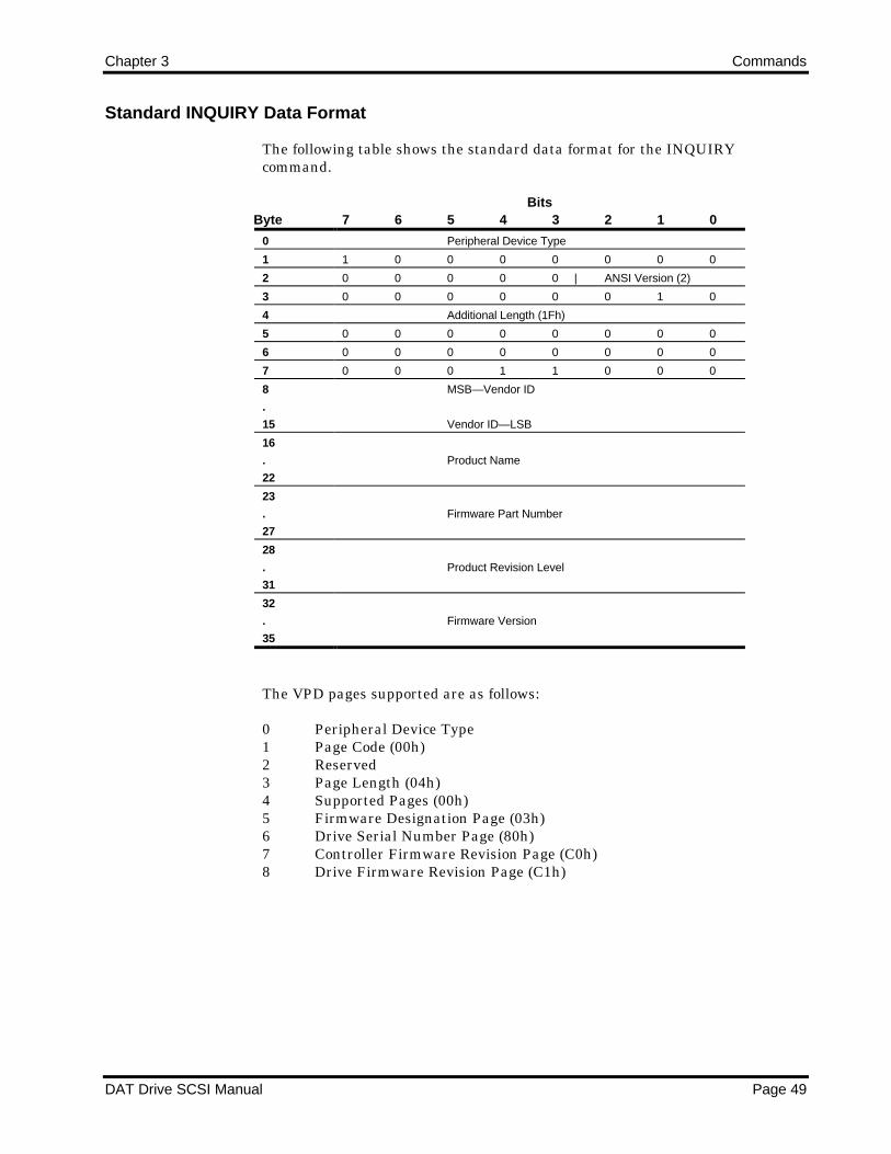
Chapter 3 Commands
DAT Drive SCSI Manual Page 49
Standard INQUIRY Data Format
The following table shows the standard data format for the INQUIRYcommand.
ByteBits
7 6 5 4 3 2 1 0
0 Peripheral Device Type
1 1 0 0 0 0 0 0 0
2 0 0 0 0 0 | ANSI Version (2)
3 0 0 0 0 0 0 1 0
4 Additional Length (1Fh)
5 0 0 0 0 0 0 0 0
6 0 0 0 0 0 0 0 0
7 0 0 0 1 1 0 0 0
8
.
15
MSB—Vendor ID
Vendor ID—LSB
16
.
22
Product Name
23
.
27
Firmware Part Number
28
.
31
Product Revision Level
32
.
35
Firmware Version
The VPD pages supported are as follows:
0 Peripheral Device Type1 Page Code (00h)2 Reserved3 Page Length (04h)4 Supported Pages (00h)5 Firmware Designation Page (03h)6 Drive Serial Number Page (80h)7 Controller Firmware Revision Page (C0h)8 Drive Firmware Revision Page (C1h)

Commands Chapter 3
Page 50 DAT Drive SCSI Manual
Standard INQUIRY Data Format Field Descriptions
The following table describes the data format fields.
Field Name Bytes Bits Description
Peripheral
Device Type
0 0-7 This field is set to 01h to indicate a sequential access
device.
This field is set to 08h to indicate a medium changer
device if the drive is an Autoloader and the LUN=1.
Value 7Fh indicates that a logical unit is not present.
This value is returned in the case where an invalid
LUN was contained in the last Identify message sent
by the Initiator, or the LUN field of the CDB.
ANSI Version 2 0-2 This field contains 2 in compliance with ANSI standard
SCSI-2
Additional
Length
4 This field indicates that 31 bytes of additional
INQUIRY command parameters follow—beginning in
Byte 05h. This value is not changed if the Allocation
Length in the CDB is too small or too large to
accommodate the entire response.
Vendor ID 8-15 These fields contain 8 bytes of ASCII data:
SEAGATE followed by 2 spaces.
Product Name 16-22 These fields contain 7 bytes of ASCII data: "???? "
followed by a space.
Firmware Part
Number
23-27 These fields contain the 5-digit Seagate part number.
Product
Revision Level
28-31 These fields contain 4 bytes of ASCII data: "-xxx" the
xxx is the 3-digit firmware revision part number; for
example, "-001".
Firmware
Version
32-35 These fields contain the firmware version.
The Firmware Designation Page (03h) is defined as follows:
0 Peripheral Device type1 Page Code (03h)2 Reserved3 Page Length (1Ch)4-11 Reserved12-15 REV Level16-31 Reserved

Chapter 3 Commands
DAT Drive SCSI Manual Page 51
The Controller Firmware Revision Page (C0h) is defined as follows:
0 Peripheral Device Type1 Page Code (C0h)2 Reserved3 Page Length (0Dh)4 ASCII Length (0Ch)5-8 REV Level9-16 Build Date17-20 OEM Model Number
The Drive Firmware Revision Page (C1h) is defined as follows:
0 Peripheral Device Type1 Page Code (C1h)2 Reserved3 Page Length (04h)4 ASCII Length (03h)5-7 Drive Firmware Revision Level
INQUIRY Drive Serial Number Data Format Page
The following table describes the drive serial number, which is sent from thedrive to the host as data formatted in a parameter list.
ByteBits
7 6 5 4 3 2 1 0
0 Peripheral Device Type
1 Page code (80h)
2 Reserved
3 Page Length (7)
4 Drive Serial Number
5 Drive Serial Number
6 Drive Serial Number
7 Drive Serial Number
8 Drive Serial Number
9 Drive Serial Number
10 Drive Serial Number

Commands Chapter 3
Page 52 DAT Drive SCSI Manual
Drive Serial Number Data Format Field Descriptions
The following table defines the fields in the Drive Serial Number Data Format.
Field Name Bytes Bits Description
Peripheral
Device Type
0 0-7 This field is set to 01h to indicate a sequential access
device.
Page Code 1 0-7 The Page Code field is set to 80h to indicate that the
data following contain the Drive Serial Number.
Page Length 3 0-7 This field specifies the length of the Drive Serial
Number.
Drive's Serial
Number
4-6
7-10
0-7
0-7
These fields contain the drive's 3-digit prefix.
These fields contain the drive's 4-digit serial number.
Completion Status
The Completion Status for the INQUIRY command is shown in the followingtable.
Code Message Description
00h Good Status • The tape is not moved; the current position is maintained.
• The drive remains in any previously set modes.
• The drive is ready to perform any appropriate command.
02h Check Condition Extended Sense Byte 02h
Code Message Description
04h Hardware Error Parity error on SCSI bus or drive
hardware failure detected.
05h Illegal Request The CDB contains an invalid bit..

Chapter 3 Commands
DAT Drive SCSI Manual Page 53
LOAD/UNLOAD (1Bh)
The LOAD/UNLOAD command requests that the DAT drive enable or disablethe logical unit for further operations. In either case, the tape is positioned toBOT before loading or unloading.
When an UNLOAD command is executed, the tape positions to BOT, and thecartridge is ejected without an error condition. The UNLOAD command ejectsthe cartridge even if a PREVENT MEDIA REMOVAL command is in effect.
For the Autoloader, an UNLOAD command ejects the cartridge from the driveinto the storage element positioned in front of the drive and then inserts thenext cartridge in sequence.
LOAD/UNLOAD Command Descriptor Block
The following table shows the layout of the CDB.
ByteBits
7 6 5 4 3 2 1 0
0 0 0 0 1 1 0 1 1
1 0 0 0 0 0 0 0 IMMED
2 0 0 0 0 0 0 0 0
3 0 0 0 0 0 0 0 0
4 0 0 0 0 0 0 X LOAD
5 X X 0 0 0 0 Flag Link
Command Descriptor Block Field Description
The following table defines the fields in the CDB.
FieldName Bytes Bits Description
IMMED
bit
1 0 If the IMMED bit is 1, status is returned as soon as the operation is initiated.
If the IMMED bit is 0, status is not returned until the tape is positioned.
LOAD
bit
4 0 If the LOAD bit is 1, the tape moves to BOT.
If the LOAD bit is 0, the tape repositions to BOT. The tape is then ejected.
following an UNLOAD, the drive accepts and executes any valid nonmedia
access commands.

Commands Chapter 3
Page 54 DAT Drive SCSI Manual
Completion Status
The Completion Status for the LOAD/UNLOAD command is shown in thefollowing table.
Code Message Description
00h Good Status
Load = 1 (Load)
Load = 0 (Unload)
IMMED = 1
• The tape is positioned to BOT.
• The drive remains in any previously set modes.
• The drive is ready to perform any appropriate command.
• The tape is position to BOT and ejected.
• The drive remains in any previously set modes.
• The drive is ready to perform any appropriate command.
Good Status is returned once the command is transferred and verified. The
requested action may still be in progress when another command is issued.
The drive immediately completes nonmedia access commands but returns
Busy otherwise.
02h Check Condition Extended Sense Byte 02h
Code Message Description
02h Not Ready No cartridge is inserted in the drive.
04h Hardware Error Parity error on SCSI bus or drive
hardware failure detected.
05h Illegal Request • Both IMMED and Link bits are set to 1.
• The CDB contains an invalid bit.
06h Unit Attention The cartridge was changed prior to BOT or
at BOT following a LOAD command.

Chapter 3 Commands
DAT Drive SCSI Manual Page 55
LOCATE (2Bh)
The LOCATE command is used to position the tape to the specified blockaddress in the specified partition. Before the locate operation is performed, allbuffered data, filemarks, and setmarks are transferred to tape. On completion,the logical position is before the specified location.
LOCATE Command Descriptor Block
The following table shows the layout of the CDB.
ByteBits
7 6 5 4 3 2 1 0
0 0 0 1 0 1 0 1 1
1 0 0 0 0 0 BT CP 0
2 0 0 0 0 0 0 0 0
3 MSB—Block Address
4 Block Address
5 Block Address
6 Block Address—LSB
7 0 0 0 0 0 0 0 0
8 Partition
9 X X 0 0 0 0 Flag Link
Command Descriptor Block Field Description
The following table defines the fields in the CDB.
FieldName Bytes Bits Description
CP bit 1 1 If the Change Partition bit is 1, the drive changes to the partition whose
partition number is specified in the Partition field. If this bit is 0, the Partition
field is ignored.
BT bit 1 2 If the Block Address Type bit is 1, the Block Address field is the total number
of logical blocks from the beginning of partition. All filemarks and setmarks
are ignored when searching the tape. If this bit is 0, the Block Address field
is the total number of logical blocks, filemarks, and setmarks from the
beginning of partition. Filemarks and setmarks are counted when searching
the tape.
Block
Address
3-6 These fields specify the logical block address of the block to which the tape
is to be positioned. Block 0 is the first block in a partition.
Partition 8 This field is valid only when the CP bit is 1. In that case, the field specifies
the partition to select—partition 0 (00h) or partition 1 (01h). This selection
should agree with the current tape format, either single-partition or two-
partition. Partition 1 is the first physical partition on a dual-partition tape.

Commands Chapter 3
Page 56 DAT Drive SCSI Manual
LOCATE and the BT Bit
Assume that the data was written on the tape as shown in the following table.
Block 0 1 2 3 4 5 6 7 8 9 10 11 12 13BOT D S S S S S D D D F D D D EODPosition A B C D
If the Block Address Type (BT) bit is set in the CDB when the LOCATEcommand is issued, all the setmarks and/or filemarks are logically grouped withits nearest Data Block on its BOT side to form one logical block. The followingtable shows the logical blocks when the BT bit is set. In the table, the data block(block number 0) and five setmarks (block numbers 1-5) are grouped together toform one logical block. the filemark (in block number 9) would be grouped withthe data block (block number 8) to form another logical block.
Block 0 0 0 0 0 0 1 2 3 3 4 5 6 7BOT D S S S S S D D D F D D D EOD
If the BT bit is 0 in the CDB when the LOCATE command is issued, then eachfilemark and setmark on the tape is counted like the logical block whilesearching the target. See the table that follows.
Block 0 1 2 3 4 5 6 7 8 9 10 11 12 13BOT D S S S S S D D D F D D D EOD
Referring to the first table, the table below shows the tape position after eachLOCATE command is complete.
LOCATE Block Address From BT bit Tape Position1 BOT ON C1 EOD ON C1 BOT OFF A1 EPD OFF A4 BOT ON D4 EOD ON D4 BOT OFF B4 EOD OFF B

Chapter 3 Commands
DAT Drive SCSI Manual Page 57
Completion Status
The Completion Status for the LOCATE command is shown in the followingtable.
Code Message Description
00h Good Status • The tape is positioned to the logical block address specified.
• The drive remains in any previously set mode.
• The drive is ready to perform any appropriate command.
02h Check Condition Extended Sense Byte 02h
Code Message Description
02h Not Ready No cartridge is inserted in the drive.
04h Hardware Error Parity error on SCSI bus or drive
hardware failure detected.
05h Illegal Request • An illegal partition number is requested.
• The CDB contains an invalid bit.
• CP bit is set when a single-partition tape is
installed.
06h Unit Attention • The cartridge was changed prior to
accepting this command.
• The drive was reset prior to this command.
08h Blank Check The specified logical block address was not
found on tape. Tape is positioned at EOD.
That is, it is positioned after the last filemark
or set mark of the current partition. The next
WRITE command appends data to the tape.

Commands Chapter 3
Page 58 DAT Drive SCSI Manual
LOG SELECT (4Ch)
The LOG SELECT and LOG SENSE commands are used in conjunction witheach other. These commands allow the host to obtain and control statisticalinformation about cartridge usage and error rates. This information consists ofcounts related to particular events that occur. Count thresholds can beestablished which automatically generate log exception conditions.
The LOG SELECT command is used to preset counts of pages 2 and 3 to aspecific value or to reset the counts if the maximum count is reached. The logsense data is also reset by a SCSI Bus Reset or a Bus Device Reset with theexception of the page 30 and 31 data. That data cannot be reset by the initiator.
Counts of pages 2 and 3 can be read by the LOG SENSE command before areset and then restored after the reset by issuing the LOG SELECT command.
The log select data is transferred to the drive by specifying the log select pageor pages to initialize. Multiple pages can be affected by a single log select CDB.However, the LOG SENSE command can only request one page at a time.
The log select parameter data is transferred to the drive to initialize page data.The parameter data is organized using structures called log parameters. A logparameter is made up of a parameter header that contains a parameter codethat identifies the log parameter to be initialized.
The drive determines the pages used by reading log sense page 0. Any requestto initialize an unused log page causes a Check Condition. The request sensedata is set to Illegal Request, Invalid Field in the CDB.
The log parameter codes within each log page used by the drive are determinedby reading each particular log sense page. Any attempt to specify an unusedparameter causes a Check Condition. The sense data is set to Illegal Request,Invalid Field in the parameter list.
LOG SELECT Command Descriptor Block
The following table shows the layout of the CDB.
ByteBits
7 6 5 4 3 2 1 0
0 0 1 0 0 1 1 0 0
1 0 0 0 0 0 0 PCR 0
2 PC 0 0 0 0 0 0
3 0 0 0 0 0 0 0 0
4 0 0 0 0 0 0 0 0
5 0 0 0 0 0 0 0 0
6 0 0 0 0 0 0 0 0
7 MSB—Parameter List Length
8 Parameter List Length—LSB
9 X X 0 0 0 0 Flag Link

Chapter 3 Commands
DAT Drive SCSI Manual Page 59
Command Descriptor Block Field Description
The following table defines the fields in the CDB.
FieldName Bytes Bits Description
PCR bit 1 1 The Parameter Code Reset (PCR) bit is used to reset log parameters. If the
bit is set (1) and the parameter list length is set to 0, all accumulated values
are set to 0. All threshold values are set to the derfaults.
Pages 0, 30, and 31 are not reset with this bit. When the PCR bit is set, the
PC bits in the CDB are ignored.
A PCR bit of 0 does not cause the parameters to be reset.
PC bits 2 6-7 The Page Control bits select one of four possible types of log information.
The settings of these bits are shown in a subsequent table.
Parameter
List
Length
2 6-7 The Parameter List Length field specifies the length (in bytes) of the
parameter list to be transferred during the Data Out phase. A 0 length
indicates that no parameter data is to be transferred to the target.
Errors Detected in the Command Descriptor Block
The following conditions constitute errors that may be detected by the drive inrelation to the CDB. These errors cause a Check Condition. The request sensedata is set to Illegal Request, Invalid Field in the CDB.
If the PCR bit is set and the parameter list length is not 0.
A parameter list length that would cause a parameter within a valid pageto be truncated or otherwise incompletely initialized.
The settings of the PC bits select the default threshold or default accumulated valuesand the parameter list length is nonzero.
Use of the PC Bits
The Page Control bits (byte 2, bits 6-7) define the type of parameter values thatare to be sent to the drive. The following table lists the Page Control bit valuesfor the LOG SELECT CDB.
Bit 7 Bit 6 Type Requested Counts
0 0 0 Threshold values
0 1 1 Accumulated values
1 0 2 Default threshold values
1 1 3 Default accumulated values

Commands Chapter 3
Page 60 DAT Drive SCSI Manual
USE OF DEFAULT VALUES TO SET CURRENT VALUES
The threshold values can be loaded with the default threshold values by settingthe PC bits to specify the default threshold values. The Parameter List Lengthmust be set to 0.
Likewise, the accumulated values can be loaded with the default accumulatedvalues by setting the PC bits to specify the default accumulated values. TheParameter List Length must be set to 0.
The drive presets the values as follows:
The default accumulated values are set to all 0s.
The default threshold values are set to all 1s.
The default values cannot be changed. If the host issues a LOG SELECTcommand with the PC bit specifying default values when the parameter listlength is nonzero, a Check Condition is returned. The sense data is set to IllegalRequest, Invalid Field in the CDB.
The Parameter Control bytes of each parameter are preserved when the LOGSELECT command is issued with the PC bits specifying either of the defaultvalues.
SETTING ACCUMULATED VALUES DIRECTLY
The host can set the accumulated values of pages 2 and 3 to any value byspecifying the accumulated values in the PC bits and transferring the logparameters containing the new values and the Parameter Control bytes.
This ability to manually set the accumulated values allows the original countspreviously read with the LOG SENSE command to be restored. Thus, thePython drive can continue to accumulate counts after a Bus Reset, Bus DeviceReset, or a manual power cycle.
SETTING THE THRESHOLD VALUES DIRECTLY
The host can set the threshold values of pages 2 and 3 to any value byspecifying the threshold values in the PC bits and transferring the logparameters containing the new values and the Parameter Control bytes.
The threshold value is used in conjunction with the Log Parameter Control byteof the log data and the RLEC bit of the Mode Select/Sense Control Mode page todetermine if, and when, a log exception Check Condition should be generatedwhen an accumulated count is incremented.
MAXIMUM COUNTS
Threshold values are not the same as the maximum count. The maximum sizeof each counter is according to the size of the counter in bytes. When themaximum count is reached, the DU bit in the Parameter Control byte for the

Chapter 3 Commands
DAT Drive SCSI Manual Page 61
counter is set to 1 for the Log Sense data indicating that the parameter is nolonger to be updated because the maximum count has been reached.
When a counter reaches the maximum, the counter is no longer incremented. Ifa maximum value for the parameter size is reached, the count does NOT rollover and continue counting. When any counter of a page reaches maximum, allcounters of that page are no longer incremented. A LOG SELECT command canbe issued with the PC bits specifying default accumulated values to reset theaccumulated values and to allow counters to continue as normal. The DU bit ofthe affected parameter is also reset to zero.
LOG SELECT Parameter Data
The host should issue a LOG SENSE command to initialize host software whichallows
Correct determination of the pages the Python drive uses.
Determination of the parameter codes and length of each parameter.
The drive does not maintain a separate set of log parameters for each initiator.Therefore, a LOG SELECT command affects all initiators.
þ Note: The subsequent section discusses the LOG SENSE command. Thelog page codes and the log parameter codes are described in that section.
Parameter data is made up of one or more page descriptors. A page descriptor ismade up of a four-byte page header and one or more log parameters. A logparameter is made up of a four-byte parameter header and one or moreassociated parameter data bytes.
The parameter header contains a two-byte parameter code to identify theparameter, a Parameter Control byte, and a parameter length byte.
When a counter reaches its maximum value, a log exception Check Condition isgenerated if the RLEC bit is set in the Mode Select Control Mode page. Thesense data is set to Recovered Error key (01), Log Counter at Maximumqualifier, 5B/02. Bytes 15 - 17 of the Request Sense data specify the page, MSBand LSB of the Parameter Code respectively, which caused the Log Exception.The counters are defined in a following section.
The drive uses pages 0, 2, 3, 30, and 31. However, the LOG SELECT commandcan only select pages 2 and 3. The following table lists the LOG SELECT pagecodes.
Page Page Information
Bits5 4 3 2 1 0
2 Write error counts 0 0 0 0 1 0
3 Read error counts 0 0 0 0 1 1

Commands Chapter 3
Page 62 DAT Drive SCSI Manual
Pages 30 and 31 are vendor unique and refer to the DDS Tape Log and TapeCapacity, respectively. Page 0, the list of supported pages, is available only tothe LOG SENSE command.
Although the counts in page 30 are similar to those in pages 2 and 3, the page 2and 3 counts are incremented separately from those in page 30. Theaccumulated counts in pages 2 and 3 accumulate across cassettes after thecounts are initialized by the LOG SELECT command or since the last reset orpower cycle. Thus, the counts in those two pages can be used to accumulateevents in a different way than the counts in the log sense page 30.
If multiple log pages are sent, they must be sent in ascending order. All logparameters of a particular page must be sent to the drive in ascending order.Not all parameter codes need to be sent with the parameter data during theData Out phase. In that way, selected parameters of a particular page can beinitialized to any value desired.
The following conditions constitute errors that cause the drive to return aCheck Condition and to set sense data to Illegal Request, Invalid ParameterData.
If any page headers are received with unsupported page codes. (Table 4-30lists the pages that can be set by the LOG SELECT command.)
An incorrect log page length is specified in the page header.
An illegal parameter code within a valid log page.
Valid log pages are not sent in ascending order.
Parameter codes of a supported page are not sent in ascending order.
The following table shows the log page header format.
ByteBits
7 6 5 4 3 2 1 0
0 0 0 Page Code
1 0 0 0 0 0 0 0 0
2 0 0 0 0 0 0 0 0
3 Page Length (n)
The Page Code field indicates which page is being sent to the drive.
The Page Length field indicates the length of log parameters (in bytes) whichfollow the page header. If the LOG SELECT CDB parameter list lengthspecified is too small to transfer complete log parameters for the specified page,an Illegal Request, Invalid Field in the CDB, is returned.

Chapter 3 Commands
DAT Drive SCSI Manual Page 63
The following table shows a typical log parameter format.
ByteBits
7 6 5 4 3 2 1 0
0 MSB—Parameter Code
1 Parameter Code—LSB
2 DU 1 0 ETC TMC 0 0
3 Parameter Length (n-3)
4 Parameter Value
n Parameter Value
The Parameter Code field identifies which log parameter is being sent to thedrive.
The parameter codes used for the page 2 (Write Error) and page 3 (Read Error)are listed in subsequent tables.
All of the bits in byte 2 of the Log Parameter are collectively referred to as theParameter Control byte. The Parameter Control byte specifies counter controls.
The host specifies the Parameter Control byte to control
Whether or not a counter is enabled.
Whether or not a Check Condition is generated when a counter isincremented, and if so, how the Check Condition is generated.
Each Log Parameter contains only one control byte. This control byte is sharedbetween the threshold and accumulated parameters. If a LOG SELECTcommand is issued to specify the control bytes for the threshold parameter, theaccumulated Parameter Control byte is affected. The LOG SENSE data reflectsthe current setting of the control byte for the parameter.
The Parameter Control byte bits used by the drive are described in thefollowing table.
Bit Name Bytes Bits Description
Disable Update
(DU)
2 7 When set (1), this bit indicates that the host does not
want this counter to be updated.
Enable
Threshold
Comparision
(ETC)
2 4 When set (1), this bit enables the generation of a
Check Condition when an accumulated counter is
incremented and the new value meets the threshold
criteria (and MODE SELECT/SENSE Control Mode
Page RLEC bit is set). See the following heading, Use
of the TMC Field and the ETC Bit.
Threshold Met
Criteria Field
(TMC)
2 3-2 This field indicates when a Check condition should be
generated when the ETC bit is set and a counter is
updated (and MODE SELECT/SENSE Control Mode
Page RLEC bit is set). See the following heading, Use
of the TMC Field and the ETC Bit.

Commands Chapter 3
Page 64 DAT Drive SCSI Manual
The Parameter Length byte is the byte count of the parameter value that isbeing sent. This length must be equal to the length returned by the LOGSENSE command.
The Parameter Value bytes indicate the value of the selected parameter typeindicated in the CDB Parameter Code field. The initiator must select either theaccumulated or threshold values by the PC bits of the LOG SELECT CDB tosend Parameter Value bytes.
USE OF THE TMC FIELD AND THE ETC BIT
The Threshold Met Criteria (TMC) field specifies how and when a log exceptionis to be reported to the host. The Enable Threshold Comparison (ETC) bitenables or disables the generation of a Check Condition for log exceptions ofindividual log parameters. The Report Log Exception Condition (RLEC) bit ofthe MODE SELECT/SENSE Control Mode Page, when set, allows thegeneration of a Check Condition for log exceptions for each log parameter whoseETC bit is set.
An RLEC bit of zero globally disables all log exception Check Conditionsregardless of the ETC bit value of each log parameter.
When the ETC bit is set (1) (and the RLEC bit is set in the MODESELECT/SENSE Control Mode Page), a Check Condition is generated each timethe accumulated value is incremented and the threshold condition is met asdescribed in the following paragraphs.
When a counter is incremented by the drive, a check is made to determine if thethreshold comparison is enabled (according to the ETC bit) for the counter beingincremented. If comparisons are enabled, the new accumulated value iscompared with the threshold value according to the Threshold Met Criteria forthe counter. When the criteria is met (and the RLEC bit is set in the MODESELECT/SENSE Control Mode Page), a log exception Check Condition isreturned for the next command. The sense key is set to Unit Attention (06); theadditional sense code is set to Log Exception; and the additional sense codequalifier is set to Threshold Condition Met, 5B/01.
If the counter is disabled because the DU bit is set (1), no threshold conditionsare compared because the counter will not be incremented.
After the log exception is signaled by the Check Condition, the host may issuethe LOG SENSE command to determine which page and which counter (byparameter code) met the criteria or may read the sense key specific field in theREQUEST SENSE data.

Chapter 3 Commands
DAT Drive SCSI Manual Page 65
The criteria for generating a Check Condition is specified by the TMC field inbits 2 and 3 of byte 2 of the parameter header. The possible settings andresulting operation are as follows.
TMC Field Bits
3 2 Generate a Log Exception Check Condition
_____________________________________________________________________________
0 0 Whenever the accumulated value is incremented.
0 1 When the accumulated value equals the threshold.
1 0 Whenever the accumulated value does not equal the threshold.
1 1 Whenever the accumulated value is greater than the threshold value. This
setting is the default value
_____________________________________________________________________________

Commands Chapter 3
Page 66 DAT Drive SCSI Manual
LOG SENSE (4Dh)
The LOG SELECT and LOG SENSE commands are used in conjunction witheach other. These commands allow the host to obtain and control statisticalinformation. This information consists of counts related to particular eventsthat occur.
Some tabulated events (page 3) refer to errors that have occurred since theMinicartridge drive was powered on or last cleared by a LOG SELECTcommand and that have accumulated across several backup or restoreoperations on several cartridges.
The vendor unique page 30 contains statistical information that is DDS specific.This DDS information is contained in the Tape Log area on each tape orpartition. This protected reference data is tabulated and maintained for theparticular tape currently being used.
For pages 2 and 3, the LOG SELECT command is used to preset counts to aspecific value or to reset the counts if the maximum count is reached. The logsense data is reset on a SCSI Bus Reset or a Bus Device Reset.
Log sense data is obtained by specifying a log page in the Page code field of theLOG SENSE CDB. Only one page of data can be requested by the host of eachLOG SENSE command. The pages used by the drive are found by reading LogPage 0. Any request for unused pages causes a Check Condition. The sensedata are then set to Illegal Request, Invalid Field in the CDB.
LOG SENSE Command Descriptor Block
The following table shows the layout of the CDB.
ByteBits
7 6 5 4 3 2 1 0
0 0 1 0 0 1 1 0 1
1 0 0 0 0 0 0 0 0
2 PC | Page Code
3 0 0 0 0 0 0 0 0
4 0 0 0 0 0 0 0 0
5 MSB—Parameter Pointer
6 Parameter Pointer—LSB
7 MSB—Allocation Length
8 Allocation Length—LSB
9 X X 0 0 0 0 Flag Link

Chapter 3 Commands
DAT Drive SCSI Manual Page 67
Command Descriptor Block Field Description
The following table defines the fields in the CDB.
FieldName Bytes Bits Description
PC bits 2 6-7 These Page Control bits select one of four possible types of log information.
These bit settings are shown in Using Page Control Bits.
Page Code 2 0-5 This field indicates the requested page code.
Parameter
Pointer
5-6 7-0 This two-byte field specifies the beginning parameter code to be returned to
the initiator. All remaining parameter codes are returned in ascending order.
This field is invalid of page code 0. If the Parameter Pointer field is nonzero
when page 0 is requested, a Check Condition is returned. The sense data
are set to Illegal Request, Invalid Field in CDB.
Allocation
Length
7-8 7-0 The Allocation Length field specifies the maximum amount of memory space
(in bytes) which the initiator has reserved for log sense data.
The drive returns the amount of bytes contained in the requested page or the
requested Allocation Length, whichever is less. If the Allocation Length is
greater than the actual page length, the transfer is truncated.
The data for only one log sense page can be transferred with any one CDB. Logsense data is organized by pages. The parameter data for each page is precededby a four-byte page header. The page header specifies the page code returnedand the length of that page in bytes.
If the Parameter Pointer field is used to specify a starting parameter code, apage header is still returned.
Following the page header are 0 or more log parameters. Each log parameter isa special data structure that contains several description bytes and theparameter value itself. (Subsequent subsections describe the log parameterfields.)
The following table details the log sense page code field.
Bits5 4 3 2 1 0 Page Page Information
0 0 0 0 0 0 0 List of available pages
0 0 0 0 1 0 2 Write error counts
0 0 0 0 1 1 3 Read error counts
1 1 0 0 0 0 30 DDS tape log (vendor
unique)
1 1 0 0 0 1 31 Tape capacity (vendor
unique)

Commands Chapter 3
Page 68 DAT Drive SCSI Manual
Using Page Control Bits
The Page Control (PC) bits specify the type of counts that the initiator isrequesting. For page 0, the PC bits are ignored. For other pages, the PC bitsspecify the type of parameter values. The followin table lists the Page Controlbit values.
Bits7 6 Type Requested Counts
0 0 0 Threshold values
0 1 1 Accumulated values
1 0 2 Default threshold values
1 1 3 Default accumulated values
Threshold Values
The type 0 indicates the current threshold values. If threshold values arerequested, the drive returns the maximum count that each parameter code canattain (the default) or the last threshold values set by the last LOG SELECTcommand.
Threshold values for pages 2 and 3 can by changed by the initiator through theLOG SELECT command. The drive does not change these values during normaloperation.
Accumulated Values
Type 1 (accumulated vales) is the most common page control bit setting. Thistype requests the current counts for the page. These counts reflect the currentcount of events since the last power-on cycle, SCSI bus Reset, Bus Device Reset,or the last LOG SELECT command that cleared or set parameter values.
þ Note: For pages 30 and 31, the parameter values cannot be changed andare never reset. These values represent historical data regarding tapeusage and cannot be changed by the LOG SELECT command. Page 30 datais written to the tape log when the tape is ejected either manually orthrough the SCSI UNLOAD command.
Accumulated values are incremented by the drive as an event occurs. Thesepage 2 and 3 values can be updated or initialized by the initiator with the LOGSELECT command. Also, the default accumulated values (all zeros) can beloaded with the accumulated values through the LOG SELECT command.
Because the rive maintains the accumulated values in volatile memory, thevalues may be lost if a power cycle occurs. The values for page 30 are saved onthe cassette itself and are preserved. However, if a power cycle occurs beforethe cassette is ejected, the current page 30 data is lost.
The tape log values cannot be updated if the cassette is write protected.

Chapter 3 Commands
DAT Drive SCSI Manual Page 69
Default Threshold Values
The type 2 page control bit setting requests default threshold values. Thisrequest generally returns the maximum count that each parameter code canattain. For example, a two-byte field returns two bytes of all 1s; a three-bytefield returns three bytes of all 1s. These default values cannot be changed bythe LOG SELECT command. The default threshold values are loaded into thethreshold values when a reset occurs or by a LOG SELECT command with thePCR bit set.
Default Accumulated Values
The type 3 page control bit setting specifies default accumulated values. Thedefault accumulated values are all zero and cannot be changed by the LOGSELECT command. The default accumulated values are loaded into theaccumulated values when a reset occurs or when a LOG SELECT command isreceived with the PCR bit set.
Using the Parameter Pointer Field
The Parameter Pointer field specifies the starting parameter code of the pagethat is to be transferred.
If the Parameter Pointer field specifies a parameter code larger than themaximum parameter code for that page, a Check Condition is generated. Thesense data is set to Illegal Request, Invalid Field in the CDB.
For example, if the page uses parameter codes 2 through 6 and the parameterpointer field is set to 3, then the drive returns parameters 3 through 6.Likewise, if the parameter pointer is set to 1, parameters 2 through 6 arereturned.
If the Parameter Pointer field is set to 0, all parameters for that particular pageare returned up to the maximum number of bytes specified in the allocationlength.
Regardless of the starting parameter code specified in the Parameter Pointerfield, the page header is always returned.
Log Sense Pages
Only one log page is transferred to the host with a single LOG SENSE CDB.Byte 2 of the CDB specifies the page to be transferred. Each log page beginswith a four-byte header, as shown in the following table.
ByteBits
7 6 5 4 3 2 1 0
0 0 0 | Page Code
1 0 0 0 0 0 0 0 0
2 0 0 0 0 0 0 0 0
3 Page Length (n)

Commands Chapter 3
Page 70 DAT Drive SCSI Manual
The Page Code field indicates the page being returned. This data matches thepage code requested in byte 2 of the LOG SENSE CDB.
The Page Length field indicates the length of the page in bytes that follow thepage header. If the allocation length specified in the CDB is too small totransfer all of the requested page, this value is not adjusted to reflect thetruncation.
However, if the Parameter Pointer field of the CDB specifies a startingparameter code other than zero, the page length is adjusted to indicate thenumber of bytes that follow the page header.
The following subsections describe the pages.
List of Available Pages (Page 0)
Page 0 indicates the log sense pages used by the drive. To determine the size ofeach page and of each parameter in the page, the individual pages must berequested.
Page 0 is unique in that the parameter data returned does not contain logparameter headers. All other pages return a page header followed by zero ormore variable-length log parameters.
Page 0 is valid only for the LOG SENSE command. When page 0 is requested,the four-byte page header is returned followed by the page codes used—one bytefor each. the available page codes are returned in ascending order. Thefollowing table shows the page 0 data format.
ByteHEXCode Description
0 00 Header, page 0
1 00 Header, reserved
2 00 Header, page length MSB
3 07 Header, page length LSB
4 00 Page 0
5 02 Page 2
6 03 Page 3
7 30 Page 30
8 31 Page 31
9 3A Page 3A
10 3B Page 3B

Chapter 3 Commands
DAT Drive SCSI Manual Page 71
Page Code Data Format for Pages 2, 3, 30, and 31
The parameter data returned consists of a four-byte page header followed byzero or more log parameters as shown in the following illustration.
Page HeaderFirst Log Parameter
.
.
.
Last Log Parameter
A log parameter is made up of
A two-byte parameter code followed by
A Parameter Control byte
A Parameter Length byte
One or more parameter bytes
Parameter Code Field
The following table presents the Parameter Code Field format.
ByteBits
7 6 5 4 3 2 1 0
0 MSB—Parameter Code
1 Parameter Code—LSB
2 0 1 1 0 0 0 0 0
3 Parameter Length (n-3)
4 Parameter Value
n Parameter Value
The Parameter Code field identifies the log parameter being returned to theinitiator. If the Parameter Pointer field of the CDB is zero, the parameter codeof the first log parameter indicates the first parameter code supported by thedrive for this log page. Parameter codes are always returned in ascendingorder.

Commands Chapter 3
Page 72 DAT Drive SCSI Manual
All of the bits in byte 2 of the log parameter are collectively referred to as theParameter Control byte. The bit descritptions as they are returned by the LOGSENSE command are given in the following table.
Bit Name Bytes Bits Description
Disable Update
(DU)
2 7 When set (1), this bit indicates that the particular
parameter is not to be updated by the drive. This bit is
set by the drive when the accumulated value reaches
its maximum. It is also returned set if the host set the
bit for the last LOG SELECT command. The default is
zero.
For parameter types other than threshold and
accumulated values, this bit is always 0.
Enable
Threshold
Comparision
(ETC)
2 4 This bit is returned as set by the last LOG SELECT
command. The default is zero.
Threshold Met
Criteria Field
(TMC)
2 3-2 This field is returned as set by the last LOG SELECT
command. As the default, both bits of this field are
returned set.
The Parameter Length byte is the byte count of the parameter value thatfollows. This length is not adjusted to match any truncation.
The Parameter Value bytes are the actual data requested according to the PCbits of the CDB.
Write Error Counts (page 2)
Page 2 contains the Write Error counts, which are tabulations of the possibleerrors (if any) encountered during writing to tape.
The page 2 parameter codes for write errors are listed in the following table.
ParameterCode Length Name
0002 2 Total rewrites
0003 3 Total errors corrected
0004 2 Not applicable (always returns 0)
0005 4 Total bytes processed (written)
0006 2 Total uncorrectable errors
8007 2 Rewrites since last read-type operation
The total rewrite count is incremented each time a frame sequence is rewrittenon tape. Rewrites are used to recover from media errors detected by the RAW(read-after-write) checking feature of the drive.
The total errors corrected count is the same as the total rewrite count.
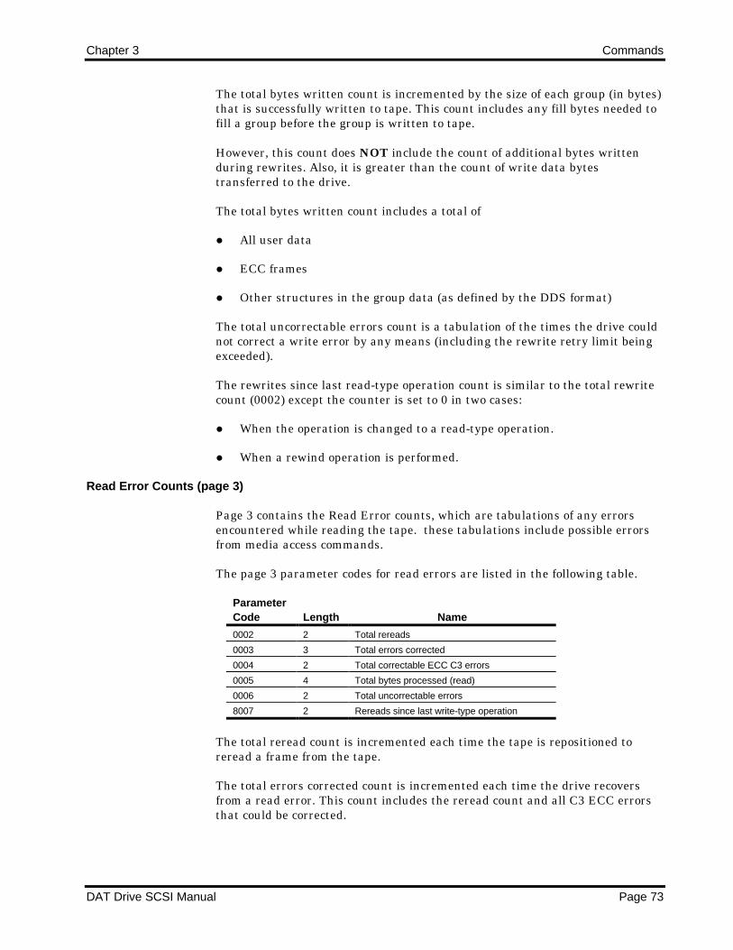
Chapter 3 Commands
DAT Drive SCSI Manual Page 73
The total bytes written count is incremented by the size of each group (in bytes)that is successfully written to tape. This count includes any fill bytes needed tofill a group before the group is written to tape.
However, this count does NOT include the count of additional bytes writtenduring rewrites. Also, it is greater than the count of write data bytestransferred to the drive.
The total bytes written count includes a total of
All user data
ECC frames
Other structures in the group data (as defined by the DDS format)
The total uncorrectable errors count is a tabulation of the times the drive couldnot correct a write error by any means (including the rewrite retry limit beingexceeded).
The rewrites since last read-type operation count is similar to the total rewritecount (0002) except the counter is set to 0 in two cases:
When the operation is changed to a read-type operation.
When a rewind operation is performed.
Read Error Counts (page 3)
Page 3 contains the Read Error counts, which are tabulations of any errorsencountered while reading the tape. these tabulations include possible errorsfrom media access commands.
The page 3 parameter codes for read errors are listed in the following table.
ParameterCode Length Name
0002 2 Total rereads
0003 3 Total errors corrected
0004 2 Total correctable ECC C3 errors
0005 4 Total bytes processed (read)
0006 2 Total uncorrectable errors
8007 2 Rereads since last write-type operation
The total reread count is incremented each time the tape is repositioned toreread a frame from the tape.
The total errors corrected count is incremented each time the drive recoversfrom a read error. This count includes the reread count and all C3 ECC errorsthat could be corrected.

Commands Chapter 3
Page 74 DAT Drive SCSI Manual
þ Note: This count does NOT include any frames read that were rewrittenwhen the tape was recorded.
The total correctable ECC error count is incremented each time the ECCprocess corrects one to two erroneous tracks read from the tape. Forperformance reasons, the ECC process corrects errors rather than retrying ifthe tracks in error are less than three; otherwise, a reread is performed.
þ Note: This count is a count of the correctable C3 errors ONLY. It doesNOT include the C1 or C2 ECC errors normally encountered while readingDDS-formatted cassettes.
The total bytes read count is incremented by the size of each group (in bytes)that is successfully read from the tape. This count includes overhead bytes (asdefined by the DDS format specification) which were read from the group.
However, this count does NOT include any additional rewritten frames thatwere read nor any rereads. Also, it is greater than the count of read data bytestransferred.
The total uncorrectable errors count is a tabulation of the times the drive couldnot correct a read error by any means (including the reread retry limit beingexceeded).
The rereads since last write-type operation count is similar to the total rereadcount (0002) except the counter is set to 0 in two cases:
When the operation is changed to a write-type operation.
When a rewind operation is performed.
DDS Tape Log (page 30)
Page 30, the DDS Tape Log page, allows you to obtain the information lastwritten to the DDS Tape Log. Each time the cartridge is ejected the Tape Log isupdated. This log contains two types of counts:
The Previous counts indicate events from the previous usage cycle of thecassette. (A usage cycle is composed of a single cartridge insertion, use, andejection.)
The Total counts accumulate events over the life of the cassette since thecassette was first initialized by a format process.
When a cartridge is formatted, the total and previous counts are initialized to 0.The previous counts in this page are updated when a previously formattedcassette is inserted to indicate the counts from the previous usage of the tape.The previous counts remain consistent through the usage cycle. Previous countscan be inspected with the LOG SENSE command.
If no activity occurs during the usage cycle, then the previous counts are all setto 0 and the Load Count is incremented by 1.

Chapter 3 Commands
DAT Drive SCSI Manual Page 75
When a previously used cartridge is inserted, the total counts are updated tothe values contained in the Tape Log of the inserted cassette. The total countscan be read with the LOG SENSE command.
Also, page 30 contains a set of current counts. The current usage counts are notpart of the Tape Log. They are initialized to 0 when the cartridge is inserted.While the tape is in use, the current usage counts are incremented according tothe DDS format definitions as an event occurs. These counts cannot be changedby the initiator.
When the cartridge is ejected or the UNLOAD command is received, the currentusage counts are saved in the previous counts. The total counts are alsoupdated to indicate the new totals. This updated data is written to the tape inthe Tape Log area. The Tape Log data is not cleared by any reset and cannot bechanged with the LOG SELECT command.
þ Note: If power is lost before the update data is written to the tape, theTape Log area is not updated. Also, if the cassette is write protected, theTape Log area is not updated when the cassette is ejected. The drive doesNOT post a Check Condition for this case.
Each page 30 count is a positive binary value. The counts do not overflow. Oncea count reaches its maximum value, that maximum value is always returned.The counts do not roll over at the maximum value.
A single-partition tape contains one Tape Log; a dual-partition tape containstwo Tape Logs. The appropriate Tape Log is returned as determined by thepreviously selected partition.
The page 30 parameter codes are listed in the following table.
Name Code Length Description
Current Groups
Written
0001 3* This count is the number of groups written to the
partition since the cartridge was inserted. Each group
contains 126 KB of data.
Current
Rewritten
Frames
0002 2 This count is the number of rewritten frames withing
the partitions since the cartridge was inserted. It is
incremented by one each time a series of frames is
rewritten. Frames are rewritten following an error
detected by the RAW check. If the data written during
the rewrite is also found to be bad by the RAW check,
the series of frames is rewritten again, and this count
is incremented by 1 again.
Current Groups
Read
0003 3* This count is the number of groups read from the
cartridge since it was inserted.
Current ECC
C3 Corrections
0004 2 This count is the nubmer of times the drive used the
C3 ECC correction to recover data from the partition
since the cartridge was inserted.
Previous
Groups Written
0005 3* This count is the number of groups written to the
partition during the last cartridge usage cycle.
*Most significant 4 bits are 0.

Commands Chapter 3
Page 76 DAT Drive SCSI Manual
Name Code Length Description
Previous
Rewritten
Frames
0006 2 This count is the number of frames rewritten in the
partition during the last cartridge usage cycle. It is
greater than or equal to the last current rewritten
frames count prior to the Tape Log being updated
when the cartridge is ejected.
Previous
Groups Read
0007 3* This count is the number of groups read from the
partition during the last cartridge usage cycle.
Previous ECC
C3 Corrections
0008 2 This count is the number of times the drive used C3
ECC correction to recover data from the partition
during the last cartridge usage cycle.
Total Groups
Written
0009 4 This count is the number of groups written since the
partition was formatted. This count accumulates over
the life of the cartridge but is zeroed if the tape is
formatted again.
Total Rewritten
Frames
000A 3 This count is the total number of times frames were
rewritten within the partition since the partition was
formatted. It is incremented by one each time a series
of frames is rewritten following an error detected by
the RAW check. It accumulates over the life of the
cartridge but is zeroed if the tape is formatted again.
Total Groups
Read
000B 4 This count is the number of groups read from the
partition since it was formatted. It accumulates over
the life of the cartridge but is zeroed if the tape is
formatted again.
Total ECC C3
Corrections
000C 3 This count is the number of times the drive used C3
ECC correction to recover data from the partition since
the tape was formatted. It accumulates over the life of
the cartridge but is zeroed if the tape is formatted
again.
Load Count 000D 2 This count is the number of times the tape has been
loaded over the life of the tape since it was formatted.
One load is the same as a usage cycle (inserting,
using, and subsequent ejection of the cartridge). It
accumulates over the life of the cartridge but is zeroed
if the tape is formatted again. In a dual-partition tape,
only one load count is maintained.
*Most significant 4 bits are 0.
Tape Capacity Page (page 31)
Page 31, the Tape Capacity page, allows you to obtain information about totaland remaining storage capacity for each partition.
Host software can use this page to determine cassette size and remainingcapacity while writing to the tape.

Chapter 3 Commands
DAT Drive SCSI Manual Page 77
The Tape Capacity Page parameter codes area given in the following table.
ParameterCode Length Name
0001h 4 Remaining capacity, partition 0 (KBytes)
0002h 4 Remaining capacity, partition 1 (KBytes)
0003h 4 Maximum capacity, partition 0 (KBytes)
0004h 4 Maximum capacity, partition 1 (KBytes)
All capacities are estimates as to the maximum available user-data capacities.The actual capacity may be slightly less because of rewrites. All values are inkilobytes.
Partition 1 is the first partition on a dual-partition tape. For single-partitiontapes, only partition 0 is used.
The capacity values return the potential write data capacity according to thecurrent physical tape position. The maximum capacity never changes for aparticular formatted cartridge. Because different tape lengths are available, themaximum value is used to determine the length of the cartridge inserted andthe associated capacity of its partition(s). To obtain capacity estimates, multiplethe values returned by 1024 decimal.
Configuration Information Page (page 3A)
Page 3A, the Configuration Information page, is valid only for the Log Sensecommand. when Page 3a is requested, the four-byte page header is returnedfollowed by configuration parameter data. The parameter data returned doesnot contain log parameter headers. Each parameter is displayed in the followingformat.
ByteBits
7 6 5 4 3 2 1 0
n MSB—Parameter Number
n+1 Parameter Number
n+2 Parameter Number
n+3 Parameter Number—LSB
n+4 MSB—Configuration Parameter
n+5 Configuration Parameter
n+6 Configuration Parameter
n+7 Configuration Parameter—LSB

Commands Chapter 3
Page 78 DAT Drive SCSI Manual
The Configuration Parameters are given in the following table.
ParameterNumber Parameter
1 Raw switch settings
2 Compression enabled set by MODE SELECT
3 Decompression enabled set by MODE SELECT
4 Block size used for writing
5 Current partition
6 Prevent (1) or Allow (0) Media Removal
7 Cartridge write-protected
8 Report setmarks
9 Data compressino ratio
Firmware Debug Information Page (page 3B)
Page 3B, the Firmware Debug Information page, is valid only for the Log Sensecommand. When Page 3B is requested, the four-byte page header is returnedfollowed by firmware debug parameter data. The parameter data returned doesnot contain log parameter headers. Each parameter is displayed in the followingformat.
ByteBits
7 6 5 4 3 2 1 0
n MSB—Parameter Number
n+1 Parameter Number
n+2 Parameter Number
n+3 Parameter Number—LSB
n+4 MSB—Debug Parameter
n+5 Debug Parameter
n+6 Debug Parameter
n+7 Debug Parameter—LSB

Chapter 3 Commands
DAT Drive SCSI Manual Page 79
The Debug Parameters are given in the following table.
ParameterNumber Parameter
1 Record count
2 Group count
3 Current setting of compression enabled
4 Current setting of decompression enabled
5 PortA/PortB static RAM buffer status
6 Number of bytes in PortA
7 Group buffer status for buffers 0 through 3
8 Group buffer status for buffers 4 through 7
9 Completion status of last data transfer
10 Record offset into entity after spacing
Completion Status
The Completion Status for the LOG SENSE command is shown in the followingtable.
Code Message Description
00h Good Status
02h Check Condition Extended Sense Byte 02h
Code Message Description
02h Not Ready No cartridge is inserted in the drive.
04h Hardware Error Parity error on SCSI bus or drive
hardware failure detected.
05h Illegal Request • The CDB contains an invalid bit.
• The Page Code in the Log Page Header
specifies an unsupported log page.
• The parameter pointer is invalid.
06h Unit • Cartridge was changed prior to accepting
Attention this command
• The drive was reset prior to this command.

Chapter 3 Commands
DAT Drive SCSI Manual Page 80
MODE SELECT (15h)
The MODE SELECT command allows the host to assign device parameters.
After a power-on or SCSI reset condition, the drive sets its device parameters tothe default values. By issuing a MODE SELECT command, the host can changethe device parameters. The parameters are transferred to the drive as dataformatted in a parameter list.
Parameters assigned by the MODE SELECT command remain in effect untilthe drive receives a subsequent MODE SELECT command or a reset. TheMODE SELECT parameters are not unique to the initiator that assigned theparameters.
In multiple-initiator systems, the assigned parameters are used by all initiatorsthat access the drive. However, when a MODE SELECT command changesparameters that apply to other initiators, the drive generates a Unit Attentioncondition for all initiators except the one that issued the MODE SELECTcommand. The Additional Sense Code and Additional Sense Code Qualifier areset to Mode Parameters Changed.
The MODE SELECT command immediately checks for invalid parameters orinvalid combinations of parameters before executing. If an exception is found,the drive returns a Check Condition, and the request sense data is set to IllegalRequest.
You can issue a MODE SENSE command following a MODE SELECTcommand to determine which parameters (if any) were rounded to the nearestsupported value.
MODE SELECT Command Descriptor Block
The following table shows the layout of the CDB.
ByteBits
7 6 5 4 3 2 1 0
0 0 0 0 1 0 1 0 1
1 0 0 0 PF 0 0 0 0
2 0 0 0 0 0 0 0 0
3 0 0 0 0 0 0 0 0
4 Parameter List Length
5 X X 0 0 0 0 Flag Link
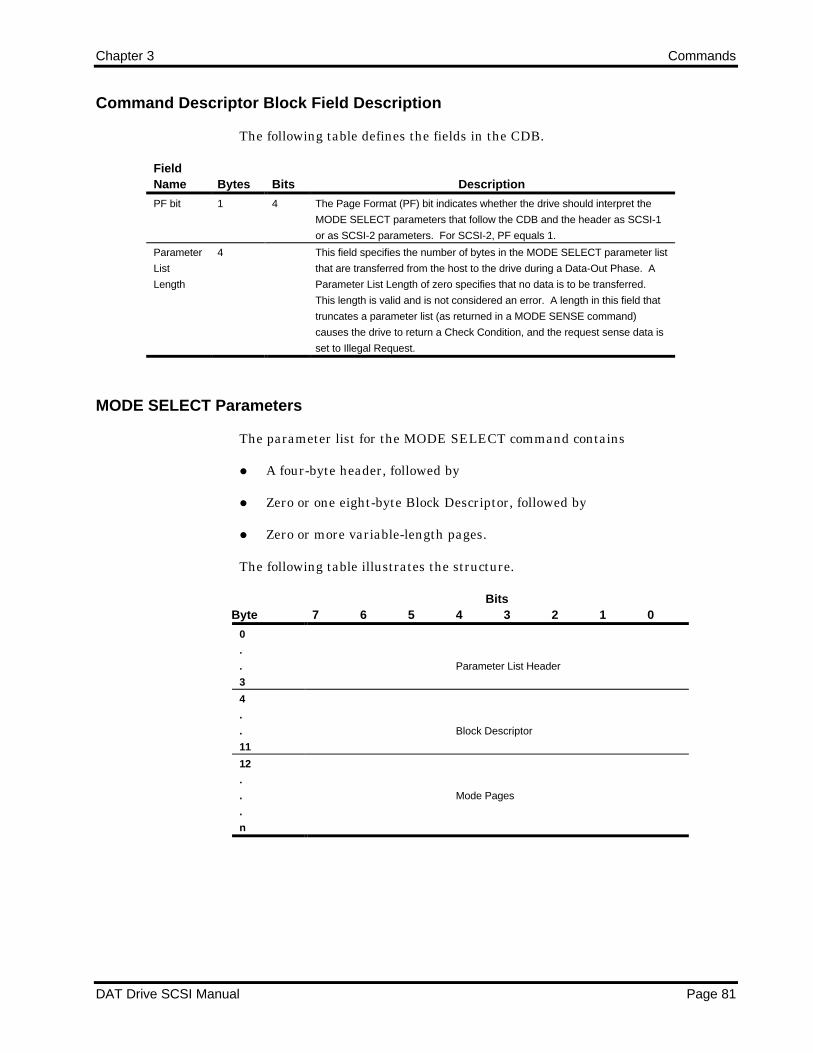
Chapter 3 Commands
DAT Drive SCSI Manual Page 81
Command Descriptor Block Field Description
The following table defines the fields in the CDB.
FieldName Bytes Bits Description
PF bit 1 4 The Page Format (PF) bit indicates whether the drive should interpret the
MODE SELECT parameters that follow the CDB and the header as SCSI-1
or as SCSI-2 parameters. For SCSI-2, PF equals 1.
Parameter
List
Length
4 This field specifies the number of bytes in the MODE SELECT parameter list
that are transferred from the host to the drive during a Data-Out Phase. A
Parameter List Length of zero specifies that no data is to be transferred.
This length is valid and is not considered an error. A length in this field that
truncates a parameter list (as returned in a MODE SENSE command)
causes the drive to return a Check Condition, and the request sense data is
set to Illegal Request.
MODE SELECT Parameters
The parameter list for the MODE SELECT command contains
A four-byte header, followed by
Zero or one eight-byte Block Descriptor, followed by
Zero or more variable-length pages.
The following table illustrates the structure.
ByteBits
7 6 5 4 3 2 1 0
0
.
.
3
Parameter List Header
4
.
.
11
Block Descriptor
12
.
.
.
n
Mode Pages

Commands Chapter 3
Page 82 DAT Drive SCSI Manual
The following table shows the Parameter List Header format.
ByteBits
7 6 5 4 3 2 1 0
0 0 0 0 0 0 0 0 0
1 0 0 0 0 0 0 0 0
2 X 0 0 1 X X X X
3 Block Descriptor Length
Parameter List Header Field Descriptions
The following table defines the fields in the Parameter List Header.
FieldName Bytes Bits Description
Block
Descriptor
Length
3 This field indicates the number of bytes of block descriptor information that
follow the MODE SELECT header.
The block descriptor length may be set to 00h, which indicates that no block
descriptor bytes are included in the parameter list. This selection is valid and
is not considered an error.
If the block descriptor length is 08h, eight bytes of block descriptor
information are specified in the parameter list.
The mode pages can be sent immediately following the header depending
on the specified parameter list length.
Parameter List—Block Descriptor
The following table presents the Parameter List block descriptor.
ByteBits
7 6 5 4 3 2 1 0
0 Density Code
1 0 0 0 0 0 0 0 0
2 0 0 0 0 0 0 0 0
3 0 0 0 0 0 0 0 0
4 0 0 0 0 0 0 0 0
5 MSB—Block Length
6 Block Length
7 Block Length—LSB

Chapter 3 Commands
DAT Drive SCSI Manual Page 83
Parameter List—Block Descriptor Field Descriptions
The following table defines the fields in the Parameter List block descriptor.
FieldName Bytes Description
Density
Code
0 The following values define this field:
Hex Code Meaning
00 Default format (DDS)
13 DDS format
7F No-op
24 DDS-2
25 DDS-3
26 DDS-4
Selecting a Density Code value of 00h or 7Fh does not alter the value returned by
the MODE SENSE command (always 13h). Selecting any density code value other
than 00, 13, or 7F results in a Check Condition. The sense data is set to Illegal
Request/Invalid Field Parameter List..
Block
Length
5-7 If this field is nonzero, it indicates the length of the fixed-length block to be read or
written when the Fixed bit is set in a READ or WRITE command. (It is acceptable
to set the Fixed bit to 0.). The default is 512-byte blocks, which may be changed at
any time by the host with a MODE SELECT command.
If this field is zero, variable-length block mode is specified, and the Fixed bit in the
READ or WRITE command must be 0. The Block Length in a READ or WRITE
command may be set in a range from 1 to 16 MB (as specified in the READ BLOCK
LIMITS command.)
Mode Page Format
The following table shows the generic Mode Page format.
ByteBits
7 6 5 4 3 2 1 0
0 0 0 | Page Code
1 Page Length
2
.
.
.
n
Mode Parameters

Commands Chapter 3
Page 84 DAT Drive SCSI Manual
The following table explains the page layout fields
FieldName Bytes Description
Page Code 0 The Page Code field identifies the format and parameters for this page
as follows:
Hex Code Page Name
01 Read/write error recovery
02 Disconnect/reconnect
0A Control mode
0E Data comperwssion control
10 Device configuration
11 Medium partition
1D Element address assignment
(Autoloader only)
1F Device capabilities
(Autoloader only)
Page
Length
1 The Page Length field specifies the length (in bytes) of the mode
parameters that follow the Page Length field.
Mode
Parameters
2-n The mode parameters are described in the following subsections.
Read/Write Error Recovery Page (01h)
The Read/Write Error Recovery page allows the host to specify the errorrecovery parameters that the drive uses when transferring data. The followingtable illustrates this page.
ByteBits
7 6 5 4 3 2 1 0
0 0 0 | Page Code (01h)
1 Page Length (0Ah)
2 0 0 0 0 1 PER 0 0
3 Read Retry Count
4 0 0 0 0 0 0 0 0
5 0 0 0 0 0 0 0 0
6 0 0 0 0 0 0 0 0
7 0 0 0 0 0 0 0 0
8 Write Retry Count
9 0 0 0 0 0 0 0 0
10 0 0 0 0 0 0 0 0
11 0 0 0 0 0 0 0 0
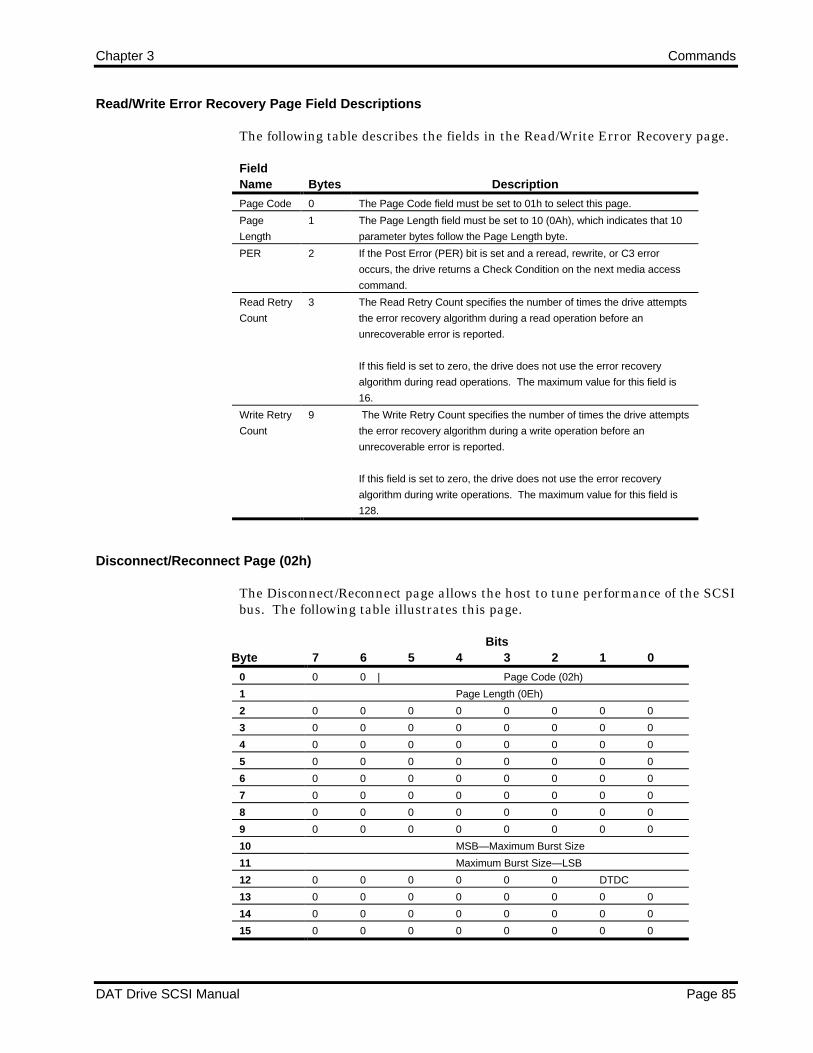
Chapter 3 Commands
DAT Drive SCSI Manual Page 85
Read/Write Error Recovery Page Field Descriptions
The following table describes the fields in the Read/Write Error Recovery page.
FieldName Bytes Description
Page Code 0 The Page Code field must be set to 01h to select this page.
Page
Length
1 The Page Length field must be set to 10 (0Ah), which indicates that 10
parameter bytes follow the Page Length byte.
PER 2 If the Post Error (PER) bit is set and a reread, rewrite, or C3 error
occurs, the drive returns a Check Condition on the next media access
command.
Read Retry
Count
3 The Read Retry Count specifies the number of times the drive attempts
the error recovery algorithm during a read operation before an
unrecoverable error is reported.
If this field is set to zero, the drive does not use the error recovery
algorithm during read operations. The maximum value for this field is
16.
Write Retry
Count
9 The Write Retry Count specifies the number of times the drive attempts
the error recovery algorithm during a write operation before an
unrecoverable error is reported.
If this field is set to zero, the drive does not use the error recovery
algorithm during write operations. The maximum value for this field is
128.
Disconnect/Reconnect Page (02h)
The Disconnect/Reconnect page allows the host to tune performance of the SCSIbus. The following table illustrates this page.
ByteBits
7 6 5 4 3 2 1 0
0 0 0 | Page Code (02h)
1 Page Length (0Eh)
2 0 0 0 0 0 0 0 0
3 0 0 0 0 0 0 0 0
4 0 0 0 0 0 0 0 0
5 0 0 0 0 0 0 0 0
6 0 0 0 0 0 0 0 0
7 0 0 0 0 0 0 0 0
8 0 0 0 0 0 0 0 0
9 0 0 0 0 0 0 0 0
10 MSB—Maximum Burst Size
11 Maximum Burst Size—LSB
12 0 0 0 0 0 0 DTDC
13 0 0 0 0 0 0 0 0
14 0 0 0 0 0 0 0 0
15 0 0 0 0 0 0 0 0

Commands Chapter 3
Page 86 DAT Drive SCSI Manual
Disconnect/Reconnect Page Field Descriptions
The following table describes the fields in the Disconnect/Reconnect page.
FieldName Bytes Bits Description
Page Code 0 The Page Code field must be set to 02h to select this page.
Page
Length
1 The Page Length field must be set to 14 (0Eh), which indicates that 14
parameter bytes follow the Page Length byte.
Maximum
Burst Size
10-11 The Maximum Burst Size field specifies the maximum amount of data
that the drive can transfer during a Data phase before disconnecting if
the initiator granted the disconnect capability.
This value is in increments of 512 bytes. That is, a value of one means
512 bytes; a value of two means 1024 bytes, and so forth.
A value of zero (0000h) indicates that no limit exists on the amount of
data transferred per connection. In that case, the drive does not have to
disconnect until all requested data is transferred.
On read operations, the drive disconnects when drive buffer is empty,
and the Allocation Length has not been satisfied. On write operations,
the drive disconnects when the drive buffer is full, and the Transfer
Length has not been exhausted.
DTDC 12 0-1 The Data Transfer Disconnect Control (DTDC) field values are as
follows:
00 Data transfer disconnect control is not used.
01 The target does not attempt to disconnect once the
data transfer of a command has been started until
all data the command is to transfer has been
completed.
10 Reserved.
11 The target does not attempt to disconnect once
the data transfer of command has been started
until the command is complete.

Chapter 3 Commands
DAT Drive SCSI Manual Page 87
Device Configuration Page (10h)
The Device Configuration page specifies the appropriate sequential accessdevice configuration. The following table illustrates this page.
ByteBits
7 6 5 4 3 2 1 0
0 0 0 | Page Code (10h)
1 Page Length (0Eh)
2 0 CAP CAF DIS RAW EN C3 N-Group
3 Active Partition
4 0 0 0 0 0 0 0 0
5 0 0 0 0 0 0 0 0
6 MSB—Write Delay Time
7 Write Delay Time—LSB
8 X X RSMK 0 0 0 0 REW
9 0 0 0 0 0 0 0 0
10 0 0 0 1 SEW 0 0 0
11 0 0 0 0 0 0 0 0
12 0 0 0 0 0 0 0 0
13 0 0 0 0 0 0 0 0
14 0 0 0 0 0 0 0 0
15 0 0 0 0 0 0 0 0

Commands Chapter 3
Page 88 DAT Drive SCSI Manual
Device Configuration Page Field Descriptions
The following table describes the fields in the Device Configuration page.
FieldName Bytes Bits Description
Page Code 0 0-5 The Page Code field must be set to 10h to select this page.
Page
Length
1 The Page Length field must be set to 14 (0Eh), which indicates that 14
parameter bytes follow the Page Length byte.
CAP bit 2 6 The CAP (Change Active Partition) bit is used to effect a partition
change. When the CAP bit is 1, the drive switches to the partition
specified in the Active Partition field. Once the MODE SELECT
command completes, the logical position is the BOP of the new
partition.
If the CAP bit is 0, no partition change results
CAF bit 2 5 The CAF (Change Active Format) bit is used to modify the tape format.
When the CAF bit is 1, bits 4-0 ofbyte may be changed.
DIS RAW 2 4 The DIS RAW (Disable Read-After-Write) bit enables and disables the
read-after-write capability. If the value is 1, read-after-write check and
rewrites are disabled. If the value is 0, read-after-write is enabled.
EN C3 2 33 The EN C3 (Enable C3) bit enables and disables C3 ECC code
generation during writing. If the value is 1, C3 ECC code is generated
during writing; if the value is 0, C3 ECC code is not generated.
N-Group 2 0-3 The N-Group field specifies the number of copies of each tape group to
record. Values greater than 0 can be used to increase reliabilty.
Active
Partition
3 The Active Partition field is valid only when the CAP bit is 1. This field
specifies the partition number of the new partition to which the drive
switches when the MODE SELECT command completes.
The drive supports a maximum of two partitions. The valid values for
this field are 0 (00h) and 1 (01h). Partition 1 is the first partition on a
dual-partition tape.
Write Delay
time
6-7 For a WRITE command, the Write Delay Time field indicates to the drive
how long in 100 millisecond increments, to delay writing buffered data to
tape after the last WRITE command.
RSMK bit 8 5 The Report Setmarks (RSMK) bit determines whether or not the drive
recognizes setmarks.
If the value is 1, the drive recognizes and reports setmarks during
appropriate read and space operations.
If the value is 0, the drive ignores setmarks. It skips any setmark it finds
during execution of read- or space-type commands. A command to
write setmarks is rejected with an Illegal Request sense key.

Chapter 3 Commands
DAT Drive SCSI Manual Page 89
FieldName Bytes Bits Description
REW bit 8 0 The Report Early Warning (REW) bit determines whether or not the
drive reports an early-warning condition on a read operation. The effect
of this bit is different for read and write operations.
For read-type operations, if this bit is 0, the drive does not report the
early-warning condition. This setting is recommended for applications
where the intent is to read data from tape until the end-of-recorded-data
(EOD) or end-of-partition (EOP) is reached.
If this bit is 1, the drive returns a Check Condition status with an End-of-
Medium (EOM) bit of 1 when the logical early-warning position is
encountered.
For write-type operations, the drive always reports the Check Condition
status when the logical early-warning position is encountered during a
WRITE command. The intent of this action is to warn the host that the
EOP is approaching and that any additional data will be written at the
risk of an unexpected EOP.
If REW = 1 and SEW = 1, the drive returns a Check Condition status
with the sense key set to Volume Overflow when the early-warning
position is encountered during write operations. The default is 0.
SEW bit 10 3 The Synchronize at Early-Warning (SEW) bit must be set to 1. It
causes the drive to flush all buffered write data to tape when the early-
warning position is encountered during writing.
Control Mode Page (0Ah)
The Control Mode page allows the host to enable or disable the generation of aCheck Condition when log parameters whose ETC bits are set to 1 meet theirThreshold Condition. The layout of this page is shown in the following table.
ByteBits
7 6 5 4 3 2 1 0
0 0 0 | Page Code (0Ah)
1 Page Length (06h)
2 0 0 0 0 0 0 0 RLEC
3 0 0 0 0 0 0 0 0
4 0 0 0 0 0 0 0 0
5 0 0 0 0 0 0 0 0
6 0 0 0 0 0 0 0 0
7 0 0 0 0 0 0 0 0
8 0 0 0 0 0 0 0 0
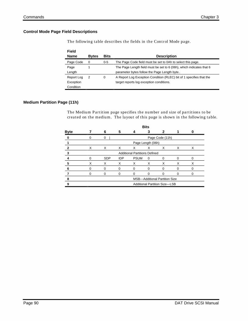
Commands Chapter 3
Page 90 DAT Drive SCSI Manual
Control Mode Page Field Descriptions
The following table describes the fields in the Control Mode page.
FieldName Bytes Bits Description
Page Code 0 0-5 The Page Code field must be set to 0Ah to select this page.
Page
Length
1 The Page Length field must be set to 6 (06h), which indicates that 6
parameter bytes follow the Page Length byte..
Report Log
Exception
Condition
2 0 A Report Log Exception Condition (RLEC) bit of 1 specifies that the
target reports log exception conditions.
Medium Partition Page (11h)
The Medium Partition page specifies the number and size of partitions to becreated on the medium. The layout of this page is shown in the following table.
ByteBits
7 6 5 4 3 2 1 0
0 0 0 | Page Code (11h)
1 Page Length (06h)
2 X X X X X X X X
3 Additional Partitions Defined
4 0 SDP IDP PSUM 0 0 0 0
5 X X X X X X X X
6 0 0 0 0 0 0 0 0
7 0 0 0 0 0 0 0 0
8 MSB—Additional Partition Size
9 Additional Partition Size—LSB

Chapter 3 Commands
DAT Drive SCSI Manual Page 91
Medium Partition Page Field Descriptions
The following table describes the fields in the Medium Partition page.
FieldName Bytes Bits Description
Page Code 0 0-5 The Page Code field must be set to 11h to select this page.
Page
Length
1 If no additional partition is to be defined or if going from a dual-partition
format to a single-partition format, the Page Length field must be set to 6
(06h), which indicates that 6 parameter bytes follow the Page Length
byte.
If an additional partition is to be defined (dual-partition), this field is set to
8 (08h).
Additional
Partitions
Defined
3 The Additional Partitions Defined field specifies the number of partitions
to add when formatting the tape. This bit may be set by the initiator to 1
(dual partitions) or 0 (single partition), which specifies the desired number
of additional partitions to format on the tape when the IDP bit = 1 or the
SCP bit = 1..
SDP bit 4 6 If the SDP bit is set to 1, the firmware automatically formats 40% of the
drive as partition 1. The following conditions are also required:
• The Additional Partition bit =1. If the Additional Partition bit =0, the
SDP bit is ignored.
• IDP bit = 0. The SDP and IDP bits cannot be set at the same time.
IDP bit 4 5 If set to 1, the Initiator Defined Partitions bit causes the Python drive to
partition the tape into 1 or 2 partitions as specified by the Additional
Partitions Defined field and the partition size descriptors.
CAUTION: Setting the IDP bit causes the tape to be reformatted to a 1-
or 2-partition tape. All previous information recorded on the cassette is
destroyed.
PSUM 4 3-4 The partition Size Unit of Measure field defines the units in which the
partition size descriptors select the partition size. The valid values are
4 3 Unit
0 0 bytes
0 1 kilobytes
1 0 megabytes
Additional
Partition
Size
8-9 The Partition Size field indicates the size of the additional partition
(partition 1) formatted on the tape when formatting a dual-partition tape.
The first physical partition is partition 1. The remainder of the tape is
partition 0.
Data Compression Control Page (0Fh)
The Data Compression (DC) Control page specifies whether or not data iscompressed during a WRITE command and whether or not data isdecompressed during a READ command. It also provides for error reportingand selection of the compression algorithm.

Commands Chapter 3
Page 92 DAT Drive SCSI Manual
The following table illustrates the DC Control page for drives with datacompression.
ByteBits
7 6 5 4 3 2 1 0
0 0 0 0 0 1 1 1 1
1 Page Length (0Eh)
2 DCE 0 0 0 0 0 0 0
3 DDE RED 0 0 0 0 0
4 0 0 0 0 0 0 0 0
5 0 0 0 0 0 0 0 0
6 0 0 0 0 0 0 0 0
7 Compression Algorithm
8 0 0 0 0 0 0 0 0
9 0 0 0 0 0 0 0 0
10 0 0 0 0 0 0 0 0
11 XX
12 0 0 0 0 0 0 0 0
13 0 0 0 0 0 0 0 0
14 0 0 0 0 0 0 0 0
15 0 0 0 0 0 0 0 0
For drives without data compression capabilities, some of the bits and bytescontain 0s. The following table illustrates the DC Control page for driveswithout data compression.
ByteBits
7 6 5 4 3 2 1 0
0 0 0 0 0 1 1 1 1
1 Page Length (0Eh)
2 0 0 0 0 0 0 0 0
3 0 RED 0 0 0 0 0
4 0 0 0 0 0 0 0 0
5 0 0 0 0 0 0 0 0
6 0 0 0 0 0 0 0 0
7 0 0 0 0 0 0 0 0
8 0 0 0 0 0 0 0 0
9 0 0 0 0 0 0 0 0
10 0 0 0 0 0 0 0 0
11 0 0 0 0 0 0 0 0
12 0 0 0 0 0 0 0 0
13 0 0 0 0 0 0 0 0
14 0 0 0 0 0 0 0 0
15 0 0 0 0 0 0 0 0

Chapter 3 Commands
DAT Drive SCSI Manual Page 93
DC Control Page Field Descriptions
The following table describes the fields in the DC Control page.
FieldName Bytes Bits Description
DCE 2 7 The DCE (Data Compression Enable) bit controls data compression. If the
value is 1, the drive compresses data received from the host during a
WRITE command before it writes the data to tape in the DDS-DC format.
If the value is 0, the drive does not compress data sent during a WRITE
command, and the host data is written to tape in the uncompressed DDS
format. This value is used for drives without data compression capabilities.
DDE 3 7 The DDE (Data Decompression Enable) bit controls data decompression.
If the value is 1, the drive decompresses data that has been compressed
on the tape before it sends the data to the host during a READ command.
If the value is 0, the drive does not return any DCLZ compressed data that
has been read from tape. Instead, the drive generates a Check Condition
with Media Error (03/70/20).
For drives without data compression capabilities, this bit is 0.
RED 3 5-6 The RED (Report Error on Decompression) bit specifies when Check
Conditions are reported to the host. If the value is 0, the drive generates a
Check Condition for every compressed entity that it cannot decompress.
For drives without data compression capability, a Check Condition is sent
to the host for every compressed entity.
If the value is 1, the drive generates Check Conditions only when the
format of the SCSI data changes. A SCSI format change occurs when
data changes from non-DCLZ compressed to uncompressed, from
uncompressed to non-DCLZ compressed, or from compressed with one
non-DCLZ algorithm to compressed with a different non-DCLZ algorithm.
A RED bit of 1 is intended to be used when reading a tape to minimize the
number of Check Conditions received by the host when data is present that
cannot be decompressed by the drive. Any media-access command, other
than the READ command, causes the drive to return to an initial state for
determining when to report the Check Conditions.
When the RED bit is first set and decompression is enabled, the drive is in
an initial state in which it expects to read either uncompressed data or data
compressed with the DCLZ algorithm.
When the RED bit is first set and decompression is disenabled, the drive is
in an initial state in which it expects to read uncompressed data. In either
case, if the expected data is not read, a Check Condition is reported.
The Request Sense information indicates further information about the
format change.
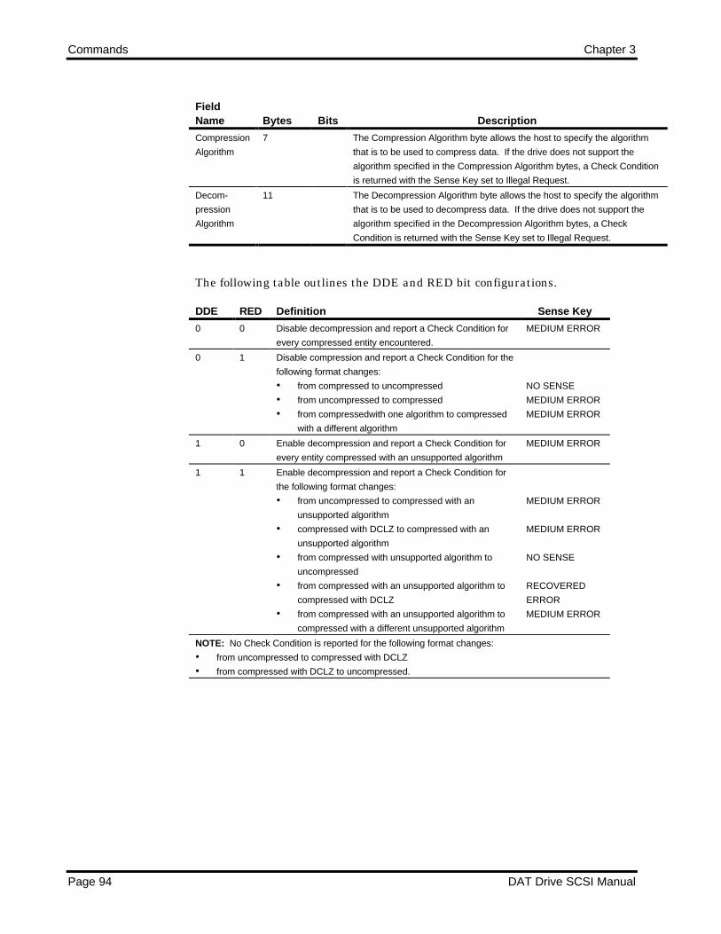
Commands Chapter 3
Page 94 DAT Drive SCSI Manual
FieldName Bytes Bits Description
Compression
Algorithm
7 The Compression Algorithm byte allows the host to specify the algorithm
that is to be used to compress data. If the drive does not support the
algorithm specified in the Compression Algorithm bytes, a Check Condition
is returned with the Sense Key set to Illegal Request.
Decom-
pression
Algorithm
11 The Decompression Algorithm byte allows the host to specify the algorithm
that is to be used to decompress data. If the drive does not support the
algorithm specified in the Decompression Algorithm bytes, a Check
Condition is returned with the Sense Key set to Illegal Request.
The following table outlines the DDE and RED bit configurations.
DDE RED Definition Sense Key
0 0 Disable decompression and report a Check Condition for
every compressed entity encountered.
MEDIUM ERROR
0 1 Disable compression and report a Check Condition for the
following format changes:
• from compressed to uncompressed
• from uncompressed to compressed
• from compressedwith one algorithm to compressed
with a different algorithm
NO SENSE
MEDIUM ERROR
MEDIUM ERROR
1 0 Enable decompression and report a Check Condition for
every entity compressed with an unsupported algorithm
MEDIUM ERROR
1 1 Enable decompression and report a Check Condition for
the following format changes:
• from uncompressed to compressed with an
unsupported algorithm
• compressed with DCLZ to compressed with an
unsupported algorithm
• from compressed with unsupported algorithm to
uncompressed
• from compressed with an unsupported algorithm to
compressed with DCLZ
• from compressed with an unsupported algorithm to
compressed with a different unsupported algorithm
MEDIUM ERROR
MEDIUM ERROR
NO SENSE
RECOVERED
ERROR
MEDIUM ERROR
NOTE: No Check Condition is reported for the following format changes:
• from uncompressed to compressed with DCLZ
• from compressed with DCLZ to uncompressed.

Chapter 3 Commands
DAT Drive SCSI Manual Page 95
The following table shows the DCE bit configuration and the supportedalgorithms. An algorithm value of 01, which is the default, can be used todetermine the supported algorithm for the drive, DCLZ (20). The value of 20 isreturned by the corresponding MODE SENSE command.
DCE Algo-rithm
Description
0 XX Compression is disabled.
1 00 Compression is disabled.
1 01 Compression is enabled using the default algorithm (DCLZ).
1 02-1F Illegal Request.
1 20 Compression is enabled using the DCLZ algorithm.
1 21-FF Illegal Request.
Completion Status
The Completion Status for the MODE SELECT command is shown in thefollowing table.
Code Message Description
00h Good Status • The drive is ready to perform any appropriate command.
• The defined mode is set and remains set until another MODE SELECT
or RESET command is issued.
• The tape position is not changed.
02h Check Condition Extended Sense Byte 02h
Code Message Description
02h Not Ready No cartridge is inserted in the drive.
05h Illegal Request • The CDB or Parameter List contains an
invalid bit.
06h Unit A • Cartridge was changed prior to accepting
Attention this command
• The drive was reset prior to this command.
The MODE SELECT command immediately checks the current page for invalidparameters or invalid combinations of parameters before executing. If such an exception isfound, the drive returns a Check Condition status byte with an Illegal Request sense key.
If the initiator does not set the Page Length field of the Mode Page to the valueindicated in the Mode Page definition (for example, 0Eh for the DeviceConfiguration Page, 01h for the Read/Write Error Recovery Page, and so forth),the drive terminates the MODE SELECT command and returns a CheckCondition status bytes with an Illegal Request sense key. The Additional SenseCode and Additional Sense Code Qualifier are set to Invalid Field in ParameterList.

Commands Chapter 3
Page 96 DAT Drive SCSI Manual
MODE SENSE (1Ah)
The MODE SENSE command allows the host to determine various drive deviceparameters. These parameters are sent from the drive to the host as dataformatted in a parameter list. This command is a complementary command tothe MODE SELECT command.
The drive terminates execution of the MODE SENSE command as follows:
When the number of bytes specified in the Allocation Length field havebeen sent to the host, or
When all available MODE SENSE data has been sent to the host.
During execution of this command, the drive does not disconnect from the host.Also, this command performs no media access.
If a MODE SELECT command has not been performed since power-on/SCSIReset, the default mode parameters are in effect.
All MODE SELECT parameters may be rounded up or down, as appropriate. AMODE SENSE command may be issued after a MODE SELECT command todetermine which parameters have been rounded.
MODE SENSE Command Descriptor Block
The following table shows the layout of the CDB.
ByteBits
7 6 5 4 3 2 1 0
0 0 0 0 1 1 0 1 0
1 0 0 0 0 DBD 0 0 0
2 PC | Page Code
3 0 0 0 0 0 0 0 0
4 Allocation Length
5 X X 0 0 0 0 Flag Link

Chapter 3 Commands
DAT Drive SCSI Manual Page 97
Command Descriptor Block Field Description
The following table defines the fields in the CDB.
FieldName Bytes Bits Description
DBD bit 1 3 If the Disable Block Descriptors (DBD) bit is set to 0, the drive always
returns the block descriptor in the MODE SENSE data.
If the DBD bit is set to 1, the drive does not return the block descriptor in the
MODE SENSE data.
NOTE: When the DBD is 1, the Block Descriptor Length in the parameter
header is set to 0.
PC field 2 6-7 The Page Control field defines the type of parameter values to be returned.
Valid values are
7 6 Unit
0 0 Report current values
0 1 Report changeable values
1 0 Report default values
If parameter type 00 (report current values) is specified, the drive returns its
current configuration to the host.
If parameter type 01 (report changeable values) is specified, any values that
may be altered by a subsequent MODE SELECT command are returned.
Any bit that can be changed is set to 1; otherwise, the bits are set to 0.
If parameter type 10 (report default values) is specified, the drive returns its
default (power-up or reset) configuration.
Page
Code
2 0-5 The Page Code field lets the initiator select the page or pages to be returned
by the drive. If Page Code is 0, only the 4-byte header and 8-byte block
descriptor are returned.
Hex Page Name
00 No page returned
01 Read/Write Error Recovery
02 Disconnect/Reconnect
0A Control Mode
0F Data Compression Control
10 Device Configuration
11 Medium Partition
1D Element address assignment (Autoloader only)
1F Device Capabilities (Autoloader only)
3F All available pages

Commands Chapter 3
Page 98 DAT Drive SCSI Manual
FieldName Bytes Bits Description
Allocation
Length
4 The Allocation Length field specifies the number of bytes the host has
allocated for returned MODE SENSE data. An Allocation Length of 0 (00h)
means that no parameter list data bytes are returned to the host. This
condition is not considered an error.
The drive terminates the Data In phase in one of two ways based on
whichever is less:
• When Allocation Length bytes have been transferred.
• When all available data have been transferred to the initiator.
MODE SENSE Parameters
The parameter list for the MODE SENSE command contains
A four-byte header, followed by
Zero or one eight-byte Block Descriptor, followed by
Zero or more variable-length pages.
The following table illustrates the structure.
ByteBits
7 6 5 4 3 2 1 0
0
.
.
3
Parameter List Header
4
.
.
11
Block Descriptor
12
.
.
.
n
Mode Pages
The MODE SENSE response data consists of a four-byte header followed by aneight-byte block descriptor. The following table shows the header format.
ByteBits
7 6 5 4 3 2 1 0
0 Mode Sense Data Length
1 Medium Type Field
2 WP 0 0 BUF 0 0 0 0

Chapter 3 Commands
DAT Drive SCSI Manual Page 99
3 Block Descriptor Length

Commands Chapter 3
Page 100 DAT Drive SCSI Manual
Parameter List Header Field Descriptions
The following table defines the fields in the MODE SENSE Header.
FieldName Bytes Bits Description
Mode
Sense
Data
Length
0 This field specifies the number of bytes in the following Mode Sense data
that is available to be transferred If the Transfer Length is smaller than the
MODE SENSE Data Length, only Transfer Length bytes of the MODE
SENSE data are transferred. The Sense Data Length does not include
itself.
BUF 2 4 If this bit is set, the drive operates in buffered mode. In buffered mode, a
WRITE command is terminated when the data is transferred to the internal
buffer of the drive. If the bit is not set, the drive operates in nonbuffered
mode. In nonbuffered mode, a WRITE command is not terminated until all
data has been transferred to tape.
WP 2 7 If this bit is 1, the tape is write-protected. If this bit is 0, the tape is write-
enabled.
Block
Descriptor
Length
3 This field indicates the number of bytes of block descriptor information that
follow the parameter header.
If the DBD bit is set to 1, the block descriptor length is set to 0 (00h), which
indicates that no block descriptor is returned in the MODE SENSE data.
If the DBD bit is set to 0, the block descriptor length is set to 8 (08h),
indicating that an eight-byte block descriptor is returned.
Medium Type Reporting
Byte 1 of the MODE SENSE header format as previously shown is the MediumType byte (accurate after tape motion completes after the initial tape insertion).This field is available for reporting the cartridge type via the SCSI bus. BeforeDDS2 cartridges and MRS cartridges became available, this field was not usefulfor DDS drives.
Because tape format selection is automatic, software applications do not usuallyneed to know the tape format. However, applications that need informationabout tape format and cartridge type can use the Medium Type field and theDensity Code field.
The values for the Medium Type byte are as follows:
30h DDS1 cartridge (13/9 µm), no MRS31h DDS1 cartridge (13/9 µm), MRS32h DDS2 cartridge (6.5 µm), MRS33h DDS3 cartridge, MRS34h DDS4 cartridge, MRS3Fh Non-DDS cartridge (cleaning cartridge)

Chapter 3 Commands
DAT Drive SCSI Manual Page 101
The Medium Type field is currently defined as RESERVED in the ANSI SCSI-2standard. This field has been used by QIC tape devices; the above values avoidconflict with QIC drives.
Parameter List—Block Descriptor
The following table presents the block descriptor.
ByteBits
7 6 5 4 3 2 1 0
0 Density Code
1 0 0 0 0 0 0 0 0
2 0 0 0 0 0 0 0 0
3 0 0 0 0 0 0 0 0
4 0 0 0 0 0 0 0 0
5 MSB—Block Length
6 Block Length
7 Block Length—LSB
Parameter List Block Descriptor Field Descriptions
The following table defines the fields in the block descriptor.
FieldName Bytes Description
Density
Code
0 The values for the Density Code field are as follows:
13h 13µ DDS1 format
24h 24µ DDS-2 format
25h 25µ DDS-3 format
26h 26µ DDS-4 format
NOTE: Although the above values are approved by the ANSI X3T9 Technical
Committee, the values are not published in the SCSI-2 standard.
Block
Length
5-7 This field indicates the size of a fixed-length logical block. Byte 5 is the Most-
Significant-Byte (MSB); byte 7 is the Least-Significant-Byte (LSB). The default
fixed-block size for the drive is 512 bytes (200h). Block Length may be set in a
range from 1 to 224-1 bytes (as specified in the READ BLOCK LIMITS command.)
When this field is 0, the Block Length bytes indicate variable-block mode.
Mode Page Format
The following table shows the generic Mode Page format.

Commands Chapter 3
Page 102 DAT Drive SCSI Manual
ByteBits
7 6 5 4 3 2 1 0
0 0 0 | Page Code
1 Page Length
2
.
.
.
n
Mode Parameters
The following table explains the page layout fields
FieldName Bytes Description
Page Code 0 The Page Code field identifies the format and parameters for this page
as follows:
Hex Code Page Name
01 Read/write error recovery
02 Disconnect/reconnect
0A Control mode
10 Device configuration
11 Medium partition
Page
Length
1 The Page Length field specifies the length (in bytes) of the mode
parameters that follow the Page Length field.
Mode
Parameters
2-n The mode parameters are described in the following subsections.
Read/Write Error Recovery Page (01h)
The Read/Write Error Recovery page allows the host to specify the errorrecovery and reporting parameters that the drive uses when transferring data.These parameters apply to errors encountered by the media access commandsThe following table illustrates this page.
ByteBits
7 6 5 4 3 2 1 0
0 0 0 | Page Code (01h)
1 Page Length (0Ah)
2 0 0 0 0 1 PER 0 0
3 Read Retry Count
4 0 0 0 0 0 0 0 0
5 0 0 0 0 0 0 0 0
6 0 0 0 0 0 0 0 0
7 0 0 0 0 0 0 0 0
8 Write Retry Count
9 0 0 0 0 0 0 0 0
10 0 0 0 0 0 0 0 0
11 0 0 0 0 0 0 0 0

Chapter 3 Commands
DAT Drive SCSI Manual Page 103
Read/Write Error Recovery Page Field Descriptions
The following table describes the fields in the Read/Write Error Recovery page.
FieldName Bytes Bits Description
Page Code 0 0-5 The Page Code field must be set to 01h to select this page.
Page
Length
1 The Page Length field must be set to 10 (0Ah), which indicates that 10
parameter bytes follow the Page Length byte.
PER 2 2 If the Post Error bit (PER) is set and a reread, rewrite, or C3 error
occurs, the drive returns a Check Condition on the next media access
command.
Read Retry
Count
3 The Read Retry Count specifies the number of times the drive attempts
the error recovery algorithm during a read operation before an
unrecoverable error is reported. The default is 8. The maximum is 16;
the minimun is 0.
Write Retry
Count
8 The Write Retry Count specifies the number of times the drive attempts
the error recovery algorithm during a write operation before an
unrecoverable error is reported. The default is 128. The maximum is
128; the minimum is 0.
Disconnect/Reconnect Page (02h)
The Disconnect/Reconnect page allows the host to tune performance of the SCSIbus. The following table illustrates this page.
ByteBits
7 6 5 4 3 2 1 0
0 0 0 | Page Code (02h)
1 Page Length (0Eh)
2 0 0 0 0 0 0 0 0
3 0 0 0 0 0 0 0 0
4 0 0 0 0 0 0 0 0
5 0 0 0 0 0 0 0 0
6 0 0 0 0 0 0 0 0
7 0 0 0 0 0 0 0 0
8 0 0 0 0 0 0 0 0
9 0 0 0 0 0 0 0 0
10 MSB—Maximum Burst Size
11 Maximum Burst Size—LSB
12 0 0 0 0 0 0 DTDC
13 0 0 0 0 0 0 0 0
14 0 0 0 0 0 0 0 0
15 0 0 0 0 0 0 0 0

Commands Chapter 3
Page 104 DAT Drive SCSI Manual
Disconnect/Reconnect Page Field Descriptions
The following table describes the fields in the Disconnect/Reconnect page.
FieldName Bytes Bits Description
Page Code 0 0-5 The Page Code field must be set to 02h to select this page.
Page
Length
1 The Page Length field must be set to 14 (0Eh), which indicates that 14
parameter bytes follow the Page Length byte.
Maximum
Burst Size
10-11 The Maximum Burst Size field specifies the maximum amount of data
the drive can transfer during a Data phase before disconnecting if the
initiator granted the disconnect privilege.
This value is in increments of 512 bytes. That is, a value of one means
512 bytes; a value of two means 1024 bytes, and so forth.
The default value is 0 (00h), which indicates that no limit exists on the
amount of data transferred per connection.
Data
Transfer
Disconnect
Control
(DTDC)
12 0-1 The Data Transfer Disconnect Control (DTDC) field values are as
follows:
00 Data transfer disconnect control is not used.
01 The target does not attempt to disconnect once the
data transfer of a command has been started until
all data the command is to transfer has been
completed.
10 Reserved.
11 The target does not attempt to disconnect once
the data transfer of command has been started
until the command is complete.
Control Mode Page (0Ah)
The Control Mode page allows the host to enable or disable the generation of aCheck Condition when log parameters whose ETC bits are set to 1 meet theirThreshold Condition. (Refer to the LOG SELECT command and the LOGSENSE command.) The layout of this page is shown in the following table.
ByteBits
7 6 5 4 3 2 1 0
0 0 0 Page Code (0Ah)
1 Page Length (06h)
2 0 0 0 0 0 0 0 RLEC
3 0 0 0 0 0 0 0 DQUE
4 0 0 0 0 0 0 0 0
5 0 0 0 0 0 0 0 0
6 0 0 0 0 0 0 0 0
7 0 0 0 0 0 0 0 0

Chapter 3 Commands
DAT Drive SCSI Manual Page 105
Control Mode Page Field Descriptions
The following table describes the fields in the Control Mode page.
FieldName Bytes Description
Page Code 0 The Page Code field must be set to 0Ah to select this page.
Page
Length
1 The Page Length field must be set to six (06h), which indicates that 6
parameter bytes follow the Page Length byte.
Report Log
Exception
Condition
(RLEC)
2 A Report Log Exception Condition (RLEC) bit of 1 specifies that the
target reports log exception conditions. A RLEC bit of 0 specifies that
the target does not report log exception conditions. The default is 0.
Tagged
Queuing
(DQUE)
3 The Tagged Queuing (DQUE) bit flag must be set (1), which specifies
that Tagged Queuing is disabled.
Device Configuration Page (10h)
The Device Configuration page specifies the appropriate sequential accessdevice configuration. The following table illustrates this page.
ByteBits
7 6 5 4 3 2 1 0
0 0 0 | Page Code (10h)
1 Page Length (0Eh)
2 0 0 0 DIS RAW | EN C3 | N-Group
3 Active Partition
4 0 0 0 0 0 0 0 0
5 0 0 0 0 0 0 0 0
6 MSB—Write Delay Time
7 Write Delay Time—LSB
8 0 1 RSMK 0 0 0 0 REW
9 0 0 0 0 0 0 0 0
10 0 0 0 1 SEW 0 0 0
11 0 0 0 0 0 0 0 0
12 0 0 0 0 0 0 0 0
13 0 0 0 0 0 0 0 0
14 0 0 0 0 0 0 0 0
15 0 0 0 0 0 0 0 0

Commands Chapter 3
Page 106 DAT Drive SCSI Manual
Device Configuration Page Field Descriptions
The following table describes the fields in the Device Configuration page.
FieldName Bytes Bits Description
Page Code 0 0-5 The Page Code field must be set to 10h to select this page.
Page
Length
1 The Page Length field must be set to 14 (0Eh), which indicates that 14 parameter
bytes follow the Page Length byte.
DIS RAW 2 4 The DIS RAW (Disable Read-After Write) bit enables and disables the read-after
write capabilty. If the value is 1, read-after-write check and rewrites are disabled.
If the value is 0, read-after-write is enabled. The defautl value is 0.
EN C3 2 3 The EN C3 (Enable C3 bit enables and disables C3 ECC code generation during
writing. if the value is 1, C3 ECC code is generated during writing; if the value is
0, c3 ECC code is not generated. The default value is 1.
N-Group 2 0-2 The N-Group field specifies the number of repeats of each tape group to record.
Values greater than 0 can be used to increase reliability. The default value is 0.
Active
Partition
3 The Active Partition field is set to the active partition—either 00h or 01h. The
default is 0. The first partition on a dual partition tape is partition 1.
Write Delay
Time
6-7 The Write Delay Time field indicates the maximum time, in multiples of 100
milliseconds, which the drive waits with a partially full buffer before recording the
data to tape. The default value is 258h, indicating a 60-second delay.
RSMK bit 8 5 The Report Setmarks (RSMK) bit determines whether or not the drive recognizes
setmarks.
If the value is 1, the drive recognizes and reports setmarks during appropriate
read and space operations. The default value is 1.
If the value is 0, the drive ignores setmarks. It skips setmarks as if they do not
exist.
REW bit 8 0 The Report Early Warning (REW) bit determines whether or not the drive reports
an early-warning condition for read operations. For read-type operations, if this
bit is 0, the drive does not report the early-warning condition. The default setting
is 0.
If this bit is 1, the drive reports the early-warning condition when the logical early-
warning position is encountered during read operations. The drive reports early-
warning at completion of READ with no residual.
SEW bit 10 3 If set to 1, the Synchronize at Early-Warning (SEW) bit causes the drive to flush
all buffered write data to tape when the early-warning position is encountered.
If set to 0, this bit indicates that encountering the early-warning position will nto
cause th buffer to flush. The default setting is 0.
Medium Partition Page (11h)
The Medium Partition page indicates single- or dual-partition tape format. theMODE SENSE command specifying a Medium Partition page can be executedat any logical position. The tape does not need to be positioned at BOM. Thelayout of this page is shown in the following table.

Chapter 3 Commands
DAT Drive SCSI Manual Page 107
ByteBits
7 6 5 4 3 2 1 0
0 0 0 | Page Code (11h)
1 Page Length (06h)
2 Maximum Additional Partitions
3 Additional Partitions Defined
4 0 0 0 PSUM 0 0 0 0
5 0 0 0 0 0 0 1 1
6 0 0 0 0 0 0 0 0
7 0 0 0 0 0 0 0 0
8 MSB—Additional Partition Size
9 Additional Partition Size—LSB
Medium Partition Page Field Descriptions
The following table describes the fields in the Medium Partition page.
FieldName Bytes Bits Description
Page Code 0 0-5 The Page Code field must be set to 11h to select this page.
Page
Length
1 If the current format is a single-partition tape, the Page Length byte is
set to 6 (06h), indicating that 6 parameter bytes follow the Page Length
byte..
If the current format is a dual-partition tape, the Page Length is set to 8
(08h), indicating that eight parameter bytes follow the Page Length byte.
Maximum
Additional
Partitions
2 This field returns a 1 to indicate that at most only 1 additional partition
can exist for a dual-partitioned tape.
Additional
Partitions
Defined
3 This field indicates the number of additional paritions on the current
tape. A zero specifies a single-partitioned tape; a one specifies a dual-
partitioned tape.
PSUM 4 3-4 The Partition Size Unit of Measure (PSUM) field defines the units i in
which the partition size descriptors select the partition size. The valid
values are as follwo. The default is 10 (megabytes).
4 3 Unit
0 0 bytes
0 1 kilobytes
1 0 megabytes
Additional
Partition
Size
8-9 The Partition Size field defines the size of Partition 1 (the first partition
on a dual-partition tape) in the units specified in the PSUM field. Byte 8
is the MSB, and byte 9 is the LSB.
Data Compression Control Page (0Fh)
The Data Compression (DC) Control page returns the last values set by the hostwith a MODE SELECT command for data compressionnnnn control. Also, referto the MODE SELECT command Data Compression Control page.

Commands Chapter 3
Page 108 DAT Drive SCSI Manual
The following table illustrates the DC Control page for drives with datacompression.
ByteBits
7 6 5 4 3 2 1 0
0 0 0 0 0 1 1 1 1
1 Page Length (0Eh)
2 DCE DCC 0 0 0 0 0 0
3 DDE | RED | 0 0 0 0 0
4 0 0 0 0 0 0 0 0
5 0 0 0 0 0 0 0 0
6 0 0 0 0 0 0 0 0
7 Compression Algorithm
8 0 0 0 0 0 0 0 0
9 0 0 0 0 0 0 0 0
10 0 0 0 0 0 0 0 0
11 Decompression Algorithm
12 0 0 0 0 0 0 0 0
13 0 0 0 0 0 0 0 0
14 0 0 0 0 0 0 0 0
15 0 0 0 0 0 0 0 0
For drives without data compression capabilities, some of the bits and bytescontain 0s. The following table illustrates the DC Control page for driveswithout data compression.
ByteBits
7 6 5 4 3 2 1 0
0 0 0 0 0 1 1 1 1
1 Page Length (0Eh)
2 0 0 0 0 0 0 0 0
3 0 | RED | 0 0 0 0 0
4 0 0 0 0 0 0 0 0
5 0 0 0 0 0 0 0 0
6 0 0 0 0 0 0 0 0
7 0 0 0 0 0 0 0 0
8 0 0 0 0 0 0 0 0
9 0 0 0 0 0 0 0 0
10 0 0 0 0 0 0 0 0
11 0 0 0 0 0 0 0 0
12 0 0 0 0 0 0 0 0
13 0 0 0 0 0 0 0 0
14 0 0 0 0 0 0 0 0
15 0 0 0 0 0 0 0 0

Chapter 3 Commands
DAT Drive SCSI Manual Page 109
DC Control Page Field Descriptions
The following table describes the fields in the DC Control page.
FieldName Bytes Bits Description
DCE 2 7 The DCE (Data Compression Enable) bit controls data compression. This
bit contains the last value set by the host with a MODE SELECT command.
If the value is 1, the drive compresses data received from the host during a
WRITE command before it writes the data to tape in the DDS-DC format.
If the value is 0, the drive does not compress data sent during a WRITE
command, and the host data is written to tape in the uncompressed DDS
format. This value is used for drives without data compression capabilities.
DCC 2 6 The DCC (Data Compression Capable) bit values are as follows:
1 The drive is capable of doing compression
0 The drive cannot do compression
NOTE: This bit is ignored during MODE SELECT.
DDE 3 7 The DDE (Data Decompression Enable) bit contains the last value set by
teh host with a MODE SELECT command. If the value is 1, the drive
decompresses data that has been compressed on the tape before it sends
the data to the host during a READ command.
If the value is 0, the drive does not decompress any data that it sends to
the host during a READ command, and any compressed data read is sent
to the host in the entity (DDS-DC) format.
The default value is 1.
For drives without data compression capabilities, this bit is 0.

Commands Chapter 3
Page 110 DAT Drive SCSI Manual
FieldName Bytes Bits Description
RED 3 5-6 The RED (Report Error on Decompression) bit contains the last value set
by the host with a MODE SELECT command. The value specifies when
Check Conditions are reported to the host. If the value is 0, the drive
generates a Check Condition for every compressed entity that it cannot
decompress. For drives without data compression capability, a Check
Condition is sent to the host for every compressed entity.
If the value is 1, the drive generates Check Conditions only when the
format of the SCSI data changes. A SCSI format change occurs when data
changes from non-DCLZ compressed to uncompressed, from
uncompressed to non-DCLZ compressed, or from compressed with one
non-DCLZ algorithm to compressed with a different non-DCLZ algorithm.
The default value is 0.
Compression
Algorithm
7 The Compression Algorithm byte specifies the algorith that is to be used to
compress data with the DCE bit set to 1. A value of 20h in this byte
specifies the DCLZ algorithm, which is the default. If the host selects a
value of 01h, for the default algorithm, a value of 20h is returned by the
MODE SENSE data.
A value of 00 specifies that data compression is disabled. This value is
used for drives without data compression capabilities..
Decom-
pression
Algorithm
11 The Decompression Algorithm byte allows the host to specify the algorithm
that is to be used to decompress data. The byte is valid whether or not the
drive decompresses the data. The byte defaults to a value of 20h to
indicate DCLZ decompression.
For drives without data compression capabilities , the value is 00h..
The following table shows the algorithm values and meaning.
Algorithm Definition
00 The data last sent to the host was uncompressed.
20 The data last sent to the host was compressed using the DCLZ
algorithm.
01-1F
21-FF
The data last sent to the host was compressed using an algorithm
other than the DCLZ algorithm. The contents of the DDS-DC entity
header algorithm byte are returned.
Element Address Assignment Page (Autoloader Only—1Dh)
The data in the Element Address Assignment page informs the host of whichtype of elements anad how many elements of each type are supported by thecurrent configuration of the Autoloader (as defined in the EXCHANGEMEDIUM COMMAND drive). the following table shows the layout of this page
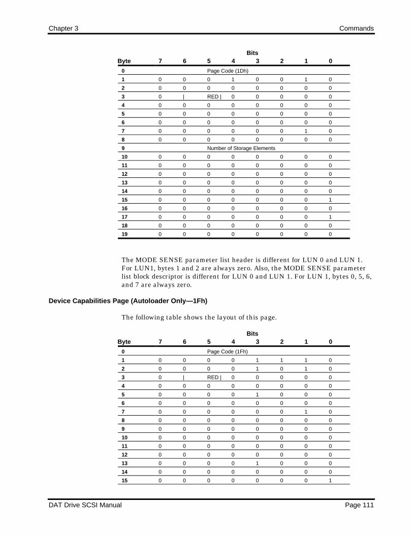
Chapter 3 Commands
DAT Drive SCSI Manual Page 111
ByteBits
7 6 5 4 3 2 1 0
0 Page Code (1Dh)
1 0 0 0 1 0 0 1 0
2 0 0 0 0 0 0 0 0
3 0 | RED | 0 0 0 0 0
4 0 0 0 0 0 0 0 0
5 0 0 0 0 0 0 0 0
6 0 0 0 0 0 0 0 0
7 0 0 0 0 0 0 1 0
8 0 0 0 0 0 0 0 0
9 Number of Storage Elements
10 0 0 0 0 0 0 0 0
11 0 0 0 0 0 0 0 0
12 0 0 0 0 0 0 0 0
13 0 0 0 0 0 0 0 0
14 0 0 0 0 0 0 0 0
15 0 0 0 0 0 0 0 1
16 0 0 0 0 0 0 0 0
17 0 0 0 0 0 0 0 1
18 0 0 0 0 0 0 0 0
19 0 0 0 0 0 0 0 0
The MODE SENSE parameter list header is different for LUN 0 and LUN 1.For LUN1, bytes 1 and 2 are always zero. Also, the MODE SENSE parameterlist block descriptor is different for LUN 0 and LUN 1. For LUN 1, bytes 0, 5, 6,and 7 are always zero.
Device Capabilities Page (Autoloader Only—1Fh)
The following table shows the layout of this page.
ByteBits
7 6 5 4 3 2 1 0
0 Page Code (1Fh)
1 0 0 0 0 1 1 1 0
2 0 0 0 0 1 0 1 0
3 0 | RED | 0 0 0 0 0
4 0 0 0 0 0 0 0 0
5 0 0 0 0 1 0 0 0
6 0 0 0 0 0 0 0 0
7 0 0 0 0 0 0 1 0
8 0 0 0 0 0 0 0 0
9 0 0 0 0 0 0 0 0
10 0 0 0 0 0 0 0 0
11 0 0 0 0 0 0 0 0
12 0 0 0 0 0 0 0 0
13 0 0 0 0 1 0 0 0
14 0 0 0 0 0 0 0 0
15 0 0 0 0 0 0 0 1

Commands Chapter 3
Page 112 DAT Drive SCSI Manual
The data in the Device Capabilities Page informs the initiator of the following:
• A cartridge can be stroed in teh data transfer and storage elements.
• A MOVE operates from storage to dat transfer elements as well as fromdata transfer to storage elements.
• An EXCHANGE only operates such that the soruce and second destinatinoaddresses must be storage elements while the first destination address mustbe the data transfer element.
Completion Status
The Completion Status for the MODE SENSE command is shown in thefollowing table.
Code Message Description
00h Good Status • The drive is ready to perform any appropriate command.
• The drive remains in any previously set mode. MODE SENSE does not
set or change any modes.
• The tape position is not changed. It remains at the previous position.
02h Check Condition Extended Sense Byte 02h
Code Message Description
02h Not Ready No cartridge is inserted in the drive.
04h Hardware Error Drive hardware failure detected.
05h Illegal Request • The CDB contains an invalid bit.
06h Unit • Cartridge was changed prior to accepting
Attention this command
• The drive was reset prior to this command.

Chapter 3 Commands
DAT Drive SCSI Manual Page 113
MOVE MEDIUM (Autoloader only) (A5h)
The MOVE MEDIUM command requests that the Autoloader move a cartridgeform a source element to a destination element. The drive must be either thesoruce or destination element.
MOVE MEDIUM Command Descriptor Block
The following table shows the layout of the CDB.
ByteBits
7 6 5 4 3 2 1 0
0 1 0 0 0 0 1 0 1
1 LUN 0 0 0 0 0
2 0 0 0 0 0 0 0 0
3 0 0 0 0 0 0 0 0
4 0 0 0 0 0 0 0 0
5 Source Address
6 0 0 0 0 0 0 0 0
7 Destination Address
8 0 0 0 0 0 0 0 0
9 0 0 0 0 0 0 0 0
10 0 0 0 0 0 0 0 0
11 X X 0 0 0 0 Flag Link
The source address specifies the location from which the cartridge is taken; thedestination address specifies the location to which the cartridge is moved. If thechanger is specified, an Illegal Request error is returne.
The following table shows the addresses of the various elements.
Source/DestinationAddress
Source/Destination Element Magazine Type(# of cartridges)
0 Changer1 Drive2 Magazine slot 1 5 or 123 Magazine slot 2 5 or 124 Magazine slot 3 5 or 125 Magazine slot 4 5 or 126 Magazine slot 5 5 or 127 Magazine slot 6 12 only8 Magazine slot 7 12 only9 Magazine slot 8 12 only10 Magazine slot 9 12 only11 Magazine slot 10 12 only12 Magazine slot 11 12 only13 Magazine slot 12 12 onlyOther (Illegal Request)

Commands Chapter 3
Page 114 DAT Drive SCSI Manual
If the MOVE MEDIUM command is received and the source element is emptyor the destination element (if different from teh source element) is full, theAutoloader returns a Check Condition and an Illegal sense key.
The source and destination address can be the drive element (address 1) or avalid cassette storage element. If the address specified is not assigned to aspecific elemtn or the drive is not the source or destination, the Autoloaderreturns a Check Condition and an Illegal Request sense key.
Completion Status
The Completion Status for the MOVE MEDIUM command is shown in thefollowing table.
Code Message Description
00h Good Status • The drive is ready for another command.
• The cartridge has been moved to the specified location. If the cartridge
was moved to the drive, it is positioned at BOT.
02h Check Condition Extended Sense Byte 02h
Code Message Description
02h Not Ready No magazine present.
04h Hardware Error Drive hardware failure detected.
05h Illegal Request • Source element is empty or destination
is full.
• Address specified is not assigned to a
specific element.
• The drive is not the source or destination.
06h Unit • Cartridge was changed prior to accepting
Attention this command
• The drive was reset prior to this command..

Chapter 3 Commands
DAT Drive SCSI Manual Page 115
PREVENT/ALLOW MEDIA REMOVAL (1Eh)
If the amber drive LED is ON because of a PREVENT command, the cartridgecannot be ejected with the eject pushbutton. If the amber drive LED is OFFbecause of an ALLOW command, the cartridge can be ejected. If the cartridge isejected (while the LED is OFF), Unit Attention or Not Ready is set on the nextcommand. If the PREVENT command is issued, the amber drive LED is alwaysON. After a Reset, the default state of the drive is in the ALLOW commandmode. An UNLOAD command ejects the cartridge even after a PREVENTcommand.
PREVENT/ALLOW MEDIA REMOVAL Command Descriptor Block
The following table shows the layout of the CDB.
ByteBits
7 6 5 4 3 2 1 0
0 0 0 0 1 1 1 1 0
1 0 0 0 0 0 0 0 0
2 0 0 0 0 0 0 0 0
3 0 0 0 0 0 0 0 0
4 0 0 0 0 0 0 0 PRVNT
5 X X 0 0 0 0 Flag Link
Command Descriptor Block Field Description
If the prevent (PRVNT) bit (byte 4, bit 0) is 1, the front panel LED is turned on.If the PRVNT bit is 0, the front panel LED is turned off. If ON (1), the cartridgecannot be ejected by using the front panel eject pushbutton.

Commands Chapter 3
Page 116 DAT Drive SCSI Manual
Completion Status
The Completion Status for the PREVENT/ALLOW MEDIA REMOVALcommand is shown in the following table.
Code Message Description
00h Good Status • The drive is ready to perform any appropriate command.
• The drive remains in any previously set mode.
• The tape position is not changed.
• If a PREVENT command was issued, the amber drive LED is always
ON. The cartridge cannot be removed.
• If an ALLOW command was sent, teh drive LED is ON only when the
tape is accessed. The tape can be removed at BOT without setting Unit
Attention Condition.
02h Check Condition Extended Sense Byte 02h
Code Message Description
04h Hardware Error Drive hardware failure detected.
05h Illegal Request The CDB or Parameter List contains an
invalid bit.
06h Unit • Cartridge was changed prior to accepting
Attention this command
• The drive was reset prior to this command.

Chapter 3 Commands
DAT Drive SCSI Manual Page 117
READ (08h)
The READ command transfers one or more bytes or blocks from the drive to theInitiator beginning with the next block on tape.
READ Command Descriptor Block
The following table shows the layout of the CDB.
ByteBits
7 6 5 4 3 2 1 0
0 0 0 0 0 1 0 0 0
1 0 0 0 0 0 0 SILI Fixed
2 MSB—Transfer Length
3 Transfer Length
4 Transfer Length—LSB
5 X X 0 0 0 0 Flag Link
Command Descriptor Block Field Description
The following table defines the fields in the CDB.
FieldName Bytes Bits Description
Fixed bit 1 0 If this bit is 1, the size of the blocks is fixed, as specified by the MODE
SELECT Block Descriptor. If it is 0, the transfer length contains the number
of bytes in the block.
Suppress
Incorrect
Length
Indicator
1 1 The SILI (Suppress Incorrect Length Indicator) bit is used to suppress
incorrect length error reporting when reading variable-length blocks.
If the SILI bit is 1 and the Fixed bit is 1, the drive returns a Check Condition
with Illegal Request sense key with an additional sense code of Invalid Field
in CDB.
When the SILI bit is 1 and Fixed bit is 0 and the only error encountered by
the drive is that the actual block length differs from the requested transfer
length, then the drive
• Returns a Check Condition if the actual block length is larger than the
requested transfer length and the Block Length field in the Mode
Parameter block descriptor is nonzero.
• Does not return a Check Condition if the actual block length is smaller
than the requested transfer length or if the actual block is larger than
the requested block and the block length in the Mode Parameter block
descriptor is 0.
Transfer 2-4 This field specifies the number of bytes or blocks to be read. When a
transfer length is 0, no data is transferred. This condition is not considered
an error.
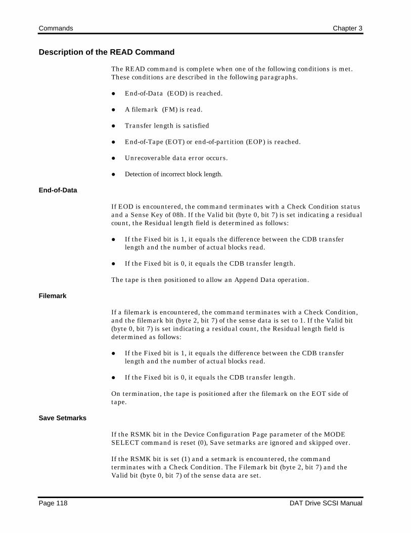
Commands Chapter 3
Page 118 DAT Drive SCSI Manual
Description of the READ Command
The READ command is complete when one of the following conditions is met.These conditions are described in the following paragraphs.
End-of-Data (EOD) is reached.
A filemark (FM) is read.
Transfer length is satisfied
End-of-Tape (EOT) or end-of-partition (EOP) is reached.
Unrecoverable data error occurs.
Detection of incorrect block length.
End-of-Data
If EOD is encountered, the command terminates with a Check Condition statusand a Sense Key of 08h. If the Valid bit (byte 0, bit 7) is set indicating a residualcount, the Residual length field is determined as follows:
If the Fixed bit is 1, it equals the difference between the CDB transferlength and the number of actual blocks read.
If the Fixed bit is 0, it equals the CDB transfer length.
The tape is then positioned to allow an Append Data operation.
Filemark
If a filemark is encountered, the command terminates with a Check Condition,and the filemark bit (byte 2, bit 7) of the sense data is set to 1. If the Valid bit(byte 0, bit 7) is set indicating a residual count, the Residual length field isdetermined as follows:
If the Fixed bit is 1, it equals the difference between the CDB transferlength and the number of actual blocks read.
If the Fixed bit is 0, it equals the CDB transfer length.
On termination, the tape is positioned after the filemark on the EOT side oftape.
Save Setmarks
If the RSMK bit in the Device Configuration Page parameter of the MODESELECT command is reset (0), Save setmarks are ignored and skipped over.
If the RSMK bit is set (1) and a setmark is encountered, the commandterminates with a Check Condition. The Filemark bit (byte 2, bit 7) and theValid bit (byte 0, bit 7) of the sense data are set.

Chapter 3 Commands
DAT Drive SCSI Manual Page 119
The Residual Length field is then set as follows:
If the Fixed bit is 1, it equals the difference between the CDB transferlength and the number of actual blocks read.
If the Fixed bit is 0, it equals the CDB transfer length.
On termination, the logical position is after the Save Setmark.
Transfer Length Satisfied
If the CDB Transfer Length is satisfied, the command completes successfullywith a Good Status, and the tape is positioned on the EOT side of the last blockread.
End of Tape (EOT) or End-of-Partition (EOP)
When the end-of-tape or end-of-partition position is encountered, the commandterminates with a Check Condition and Medium Error (03h) sense key. TheValid bit (byte 0, bit 7) and the EOM bit (byte 2, bit 6) are set.
The Residual Length field is then set as follows:
If the Fixed bit is 1, it equals the difference between the CDB transferlength and the number of actual blocks read.
If the Fixed bit is 0, it equals the CDB transfer length.
The logical position after encountering an end-of-tape or end-of-partition erroris undetermined.
Recoverable Data Error
If an error is encountered while reading, the read retry count (in the MODESELECT Read/Write Error Recovery page) specifies the maximum number ofattempts to reread the data. If none of the rereads are successful, the error isconsidered unrecoverable and is reported a such. The drive might require asmuch as six minutes to complete its error recovery procedure.
Unrecoverable Data Error
If an Unrecoverable Data Error is encountered, the READ command terminateswith Check Condition and a Medium Error (03h) sense key.
If the Valid bit (byte 0, bit 7) is set, Residual Length field equals the differencebetween the requested Transfer Length and the actual number of blocks orbytes transferred.
Incorrect Length
Writing fixed- and variable-length blocks varies according to the setting of theFixed bit.

Commands Chapter 3
Page 120 DAT Drive SCSI Manual
When the Fixed bit is set (1), one or more tape blocks can be read. The CDBTransfer Length field specifies the block count to read. The block size is thecurrent block size of the drive, which is set to 512 at power-up or after a SCSIBus Reset.
The host can change the current block size by issuing a MODE SELECTcommand with a new block descriptor parameter that specifies a new block size.If the current block size differs from the actual block size of the block beingread, the drive reports an Incorrect Length error.
When the Fixed bit is reset (0), the CDB Transfer Length field indicates thenumber of bytes to be read. When the actual block size found on tape differsfrom the CDB Transfer Length, an Incorrect Length error is reported.
The drive reports the Incorrect Length error based on the Suppress IncorrectLength Indicator (SILI) bit as follows:
If the actual block length exceeds the CDB Transfer Length, the IncorrectLength error is reported.
If the actual block length is smaller than the CDB Transfer Length and theSILI bit is 1, the drive ignores (that is, suppresses) the Incorrect Lengtherror.
If the actual block length is different than the CDB Transfer Length andthe SILI bit is 0, the drive reports the Incorrect Length error.
The drive reports the Incorrect Length error by returning a Check Condition.The Incorrect Length Indicator bit (byte 2, bit 5) of the Request Sense data isset (1) indicating the Incorrect Length error. The Valid bit (byte 0, bit 7) of theRequest Sense data is also set (1) indicating that the residual data (bytes 3through 6) is valid. The meaning of the residual data depends on the setting ofthe Fixed bit.
For reading both fixed- and variable-length blocks, the logical position afterencountering an Incorrect Length error in block N is always at the end of blockN. The following figure illustrates this position.
Current Block Size = 512 bytes/block
Block N-1 Block N Block N
N+1
512 bytes 514 bytes 512 bytes
↑↑ ↑↑Encounter ILI Logical Position
error reading after ILI error
block N

Chapter 3 Commands
DAT Drive SCSI Manual Page 121
Fixed Mode Residual Data
When the Fixed bit is set (1), the residual data is set to the CDB TransferLength minus the actual number of blocks correctly read withoutencountering an ILI error.
For example, assume the following:
The current block size is 512 bytes/block.
The drive is currently positioned before block N.
Block N contains 514 bytes.
If the host issues a READ command with a CDB Transfer Length of one,indicating one 512-byte block is to be read, the drive transfers the first 512bytes of block N; then skips the last two bytes (513 and 514) and reports aCheck Condition (caused by an Incorrect Length error). The residual is set toone. This residual is determined as follows:
CDB Transfer Length – Number of blocks correctly read withoutencountering an ILI error (1 - 0 = 1).
The logical position after the error is after byte 514 of block N.
Variable Mode Residual Data
When the Fixed bit is reset (0), the residual data is always set to the CDBTransfer Length.
For example, assume the following:
The drive is currently positioned before block N.
Block N + 1 contains 512 bytes.
The host issues a READ command with a CDB Transfer Length of 514,indicating 514 bytes of data to be read. The drive transfers the first 512 bytes ofblock N; then stops because of an Incorrect Length error. The logical positoinafter the error is after byte 512 of block N.
If the SILI bit is set (1), the drive does not report a Check Condition (caused byIncorrect Length error).
If the SILI bit is reset (0), the drive reports a Check Condition, and the residualis set to 2 (CDB Transfer Length = 514).
In the above example, if the block size of block N is 514 bytes and a READcommand specifies a Transfer Length of 512 bytes, the drive transfers the first512 bytes of blcok N; then skips the last two bytes to position itself at the end ofbyte 514 of block N. The residual is set to -2. Because the actual block lengthexceeds the CDB Transfer Length, the drive unconditionally reports CheckCondition. In this case, the residual is set to -2.
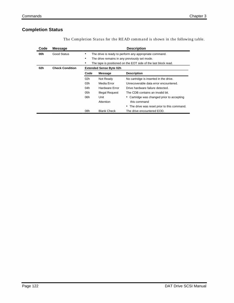
Commands Chapter 3
Page 122 DAT Drive SCSI Manual
Completion Status
The Completion Status for the READ command is shown in the following table.
Code Message Description
00h Good Status • The drive is ready to perform any appropriate command.
• The drive remains in any previously set mode.
• The tape is positioned on the EOT side of the last block read.
02h Check Condition Extended Sense Byte 02h
Code Message Description
02h Not Ready No cartridge is inserted in the drive.
03h Media Error Unrecoverable data error encountered.
04h Hardware Error Drive hardware failure detected.
05h Illegal Request The CDB contains an invalid bit.
06h Unit • Cartridge was changed prior to accepting
Attention this command
• The drive was reset prior to this command.
08h Blank Check The drive encountered EOD.

Chapter 3 Commands
DAT Drive SCSI Manual Page 123
READ BLOCK LIMITS (05h)
The READ BLOCK LIMITS command causes the drive to transfer the blocklength limits to the Initiator. The minimum block length is 1 byte; themaximum is 224-1 bytes. The minimum and maximum block limits arereturned to the Initiator in a six-byte data string.
READ BLOCK LIMITS Command Descriptor Block
The following table shows the layout of the CDB.
c Bits7 6 5 4 3 2 1 0
0 0 0 0 0 0 1 0 1
1 0 0 0 0 0 0 0 0
2 0 0 0 0 0 0 0 0
3 0 0 0 0 0 0 0 0
4 0 0 0 0 0 0 0 0
5 X X 0 0 0 0 Flag Link
Command Descriptor Block Field Description
The Command Descriptor Block does not contain command dependent fields.The values of the individual bytes in the Block Length fields are shown in thefollowing table in hexadecimal notation.
ByteBits
7 6 5 4 3 2 1 0
0 0 0 0 0 0 0 0 0
1 MSB—Maximum Block Length (FFH)
2 Maximum Block Length (FFh)
3 Maximum Block Length—LSB (FFh)
4 MSB—Minimum Block Length (00h)
5 Minimum Block Length—LSB (01h)
Block Size Definition
The host specifies the actual block size in fixed mode with the MODE SELECTcommand and in variable with the transfer/allocation length of READ andWRITE commands. The use of the MODE SENSE command determines thecurrent block size. The READ BLOCK LIMITS command indicates theminimum and maximum block size that the drive can support. Because theMODE SELECT block descriptor block sie field is 3 bytes in length, the drive islogically limited to this imposed limit. Therefore, the maximum block size isffffff hexadecimal or 16,777,215 bytes in length.

Commands Chapter 3
Page 124 DAT Drive SCSI Manual
Completion Status
The Completion Status for the READ BLOCK LIMITS command is shown inthe following table.
Code Message Description
00h Good Status • The drive is ready to perform any appropriate command.
• The drive remains in any previously set mode.
• The tape position is not changed.
02h Check Condition Extended Sense Byte 02h
Code Message Description
04h Hardware Error Drive hardware failure detected.
05h Illegal Request The CDB or Parameter List contains an
invalid bit.
06h Unit • Cartridge was changed prior to accepting
Attention this command
• The drive was reset prior to this command.

Chapter 3 Commands
DAT Drive SCSI Manual Page 125
READ DATA BUFFER (3Ch)
The READ DATA BUFFER command returns the 4-byte Read Buffer headerplus the number of bytes specified by the allocation Length field. This commandis used in conjunction with the WRITE DATA BUFFER command as adiagnostic function for testing the drive buffer memory and confirming theSCSI bus integrity. The tape is not accessed during execution of this command.
READ DATA BUFFER Command Descriptor Block
The following table shows the layout of the CDB.
ByteBits
7 6 5 4 3 2 1 0
0 0 0 1 1 1 1 0 0
1 0 0 0 0 0 | Mode
2 Buffer ID
3 MSB—Offset
4 Offset
5 Offset—LSB
6 MSB—Allocation Length
7 Allocation Length
8 Allocation Length—LSB
9 X X 0 0 0 0 Flag Link
Command Descriptor Block Field Description
The following table defines the fields in the CDB.
FieldName Bytes Bits Description
MODE 1 0-2 If MODE is 0, data is read starting at offset 0. If MODE is 3, a maximum of
four bytes of READ DATA BUFFER Header information is returned.
Buffer ID 2 If MODE is 2, only Buffer ID=0 is valid.
Offset 3-5 If MODE is 2, Offset is the offset where data reading begins. If MODE is 0 or
3, Offset must equal 0.
Allocation
Length
6-8 The Allocation Length specifies the maximum number of bytes the Initiator
allocated for returned data. For Mode 0, it includes a four-byte header
followed by the drives buffer data bytes returned to the Initiator during the
Data-In Phase. For Mode 2, it is the total number of drive buffer data
returned.
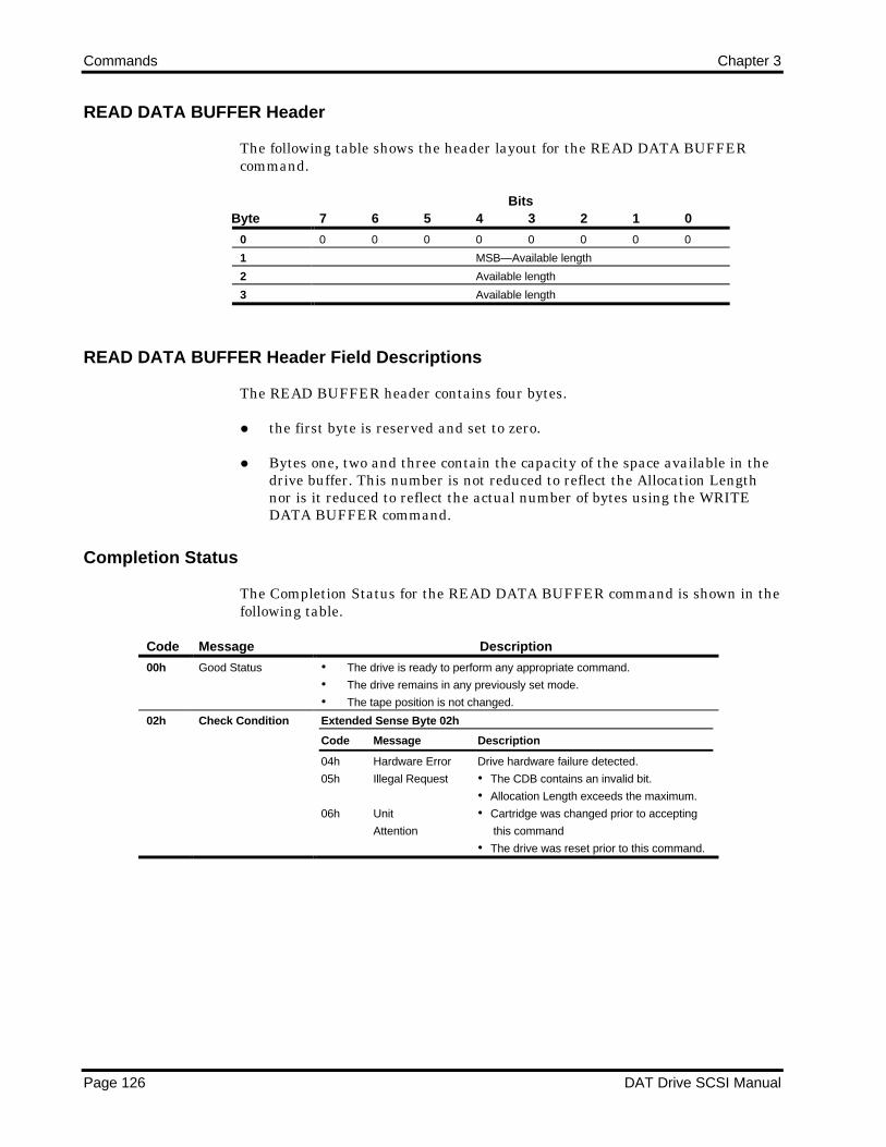
Commands Chapter 3
Page 126 DAT Drive SCSI Manual
READ DATA BUFFER Header
The following table shows the header layout for the READ DATA BUFFERcommand.
ByteBits
7 6 5 4 3 2 1 0
0 0 0 0 0 0 0 0 0
1 MSB—Available length
2 Available length
3 Available length
READ DATA BUFFER Header Field Descriptions
The READ BUFFER header contains four bytes.
the first byte is reserved and set to zero.
Bytes one, two and three contain the capacity of the space available in thedrive buffer. This number is not reduced to reflect the Allocation Lengthnor is it reduced to reflect the actual number of bytes using the WRITEDATA BUFFER command.
Completion Status
The Completion Status for the READ DATA BUFFER command is shown in thefollowing table.
Code Message Description
00h Good Status • The drive is ready to perform any appropriate command.
• The drive remains in any previously set mode.
• The tape position is not changed.
02h Check Condition Extended Sense Byte 02h
Code Message Description
04h Hardware Error Drive hardware failure detected.
05h Illegal Request • The CDB contains an invalid bit.
• Allocation Length exceeds the maximum.
06h Unit • Cartridge was changed prior to accepting
Attention this command
• The drive was reset prior to this command.

Chapter 3 Commands
DAT Drive SCSI Manual Page 127
READ ELEMENT STATUS (Autoloader Only) (B8h)
The READ ELEMENT STATUS command requests the Autolaoder to report thestatus of its elements to the host. The status of ALL element types are reported.
READ ELEMENT STATUS Command Descriptor Block
The following table shows the layout of the CDB.
ByteBits
7 6 5 4 3 2 1 0
0 1 0 1 1 1 0 0 0
1 LUN 0 0 Element Type Code
2 0 0 0 0 0 0 0 0
3 Starting Element Address
4 MSB—Number of Elements
5 Number of Elements—LSB
6 0 0 0 0 0 0 0 0
7 MSB—Allocation Length
8 Allocation Length
9 Allocation Length—LSB
10 0 0 0 0 0 0 0 0
11 X X 0 0 0 0 Flag Link
The starting element address specifies the minimum element address to report.Only element addresses greater than or equal to the starting element addressare reported. If the starting element address is undefined, an Illegal RequestCheck Condition is generated.
The number of elements specifies the maximum number of element descriptorsto be reported by the target for this command. If the Allocation Length is notsufficient to transfer all of the requested element descriptors, the Autoloadertransfers all the descriptors that can be completely transferred. This situation isnot considered an error.
Element Status Data
The data returned by the READ ELEMENT STATUS command consists of an8-byte header, followed by one or three element status pages. Within eachstatus page are the appropriate element descriptors. The Element type Codecan be 0, 1, 2, or 4.
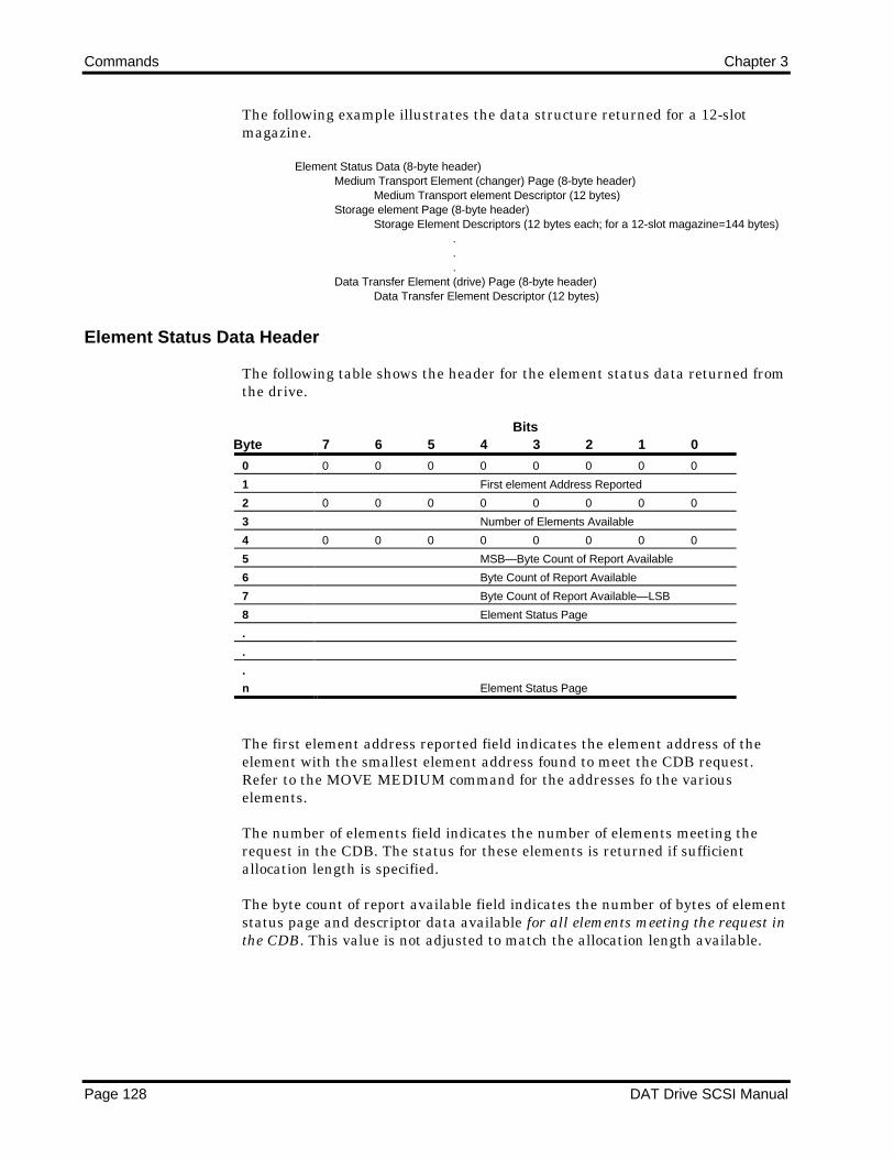
Commands Chapter 3
Page 128 DAT Drive SCSI Manual
The following example illustrates the data structure returned for a 12-slotmagazine.
Element Status Data (8-byte header)Medium Transport Element (changer) Page (8-byte header)
Medium Transport element Descriptor (12 bytes)Storage element Page (8-byte header)
Storage Element Descriptors (12 bytes each; for a 12-slot magazine=144 bytes)...
Data Transfer Element (drive) Page (8-byte header)Data Transfer Element Descriptor (12 bytes)
Element Status Data Header
The following table shows the header for the element status data returned fromthe drive.
ByteBits
7 6 5 4 3 2 1 0
0 0 0 0 0 0 0 0 0
1 First element Address Reported
2 0 0 0 0 0 0 0 0
3 Number of Elements Available
4 0 0 0 0 0 0 0 0
5 MSB—Byte Count of Report Available
6 Byte Count of Report Available
7 Byte Count of Report Available—LSB
8 Element Status Page
.
.
.
n Element Status Page
The first element address reported field indicates the element address of theelement with the smallest element address found to meet the CDB request.Refer to the MOVE MEDIUM command for the addresses fo the variouselements.
The number of elements field indicates the number of elements meeting therequest in the CDB. The status for these elements is returned if sufficientallocation length is specified.
The byte count of report available field indicates the number of bytes of elementstatus page and descriptor data available for all elements meeting the request inthe CDB. This value is not adjusted to match the allocation length available.
Chapter 3 Commands
DAT Drive SCSI Manual Page 129
Element Status Page Header
Each of the three Autoloader element status pages includes an 8-byte headerfollowed by one or more element descriptors. The following table shows theheader for an element status page.

Commands Chapter 3
Page 130 DAT Drive SCSI Manual
ByteBits
7 6 5 4 3 2 1 0
0 Element Type Code
1 0 0 0 0 0 0 0 0
2 0 0 0 0 0 0 0 0
3 0 0 0 0 0 0 0 0
4 0 0 0 0 0 0 0 0
5 MSB—Byte Count of Descriptor Available
6 Byte Count of Descriptor Available
7 Byte Count of Descriptor Available—LSB
8 Element Descriptor
.
.
.
n Element Descriptor
The element type code field indicates the element type reported in this field.The following table defines the element type codes.
Code Element Type Number of Descriptors01h Medium Transport (changer) 1
02h Storage 5 or 12
04h Data Transfer (drive) 1
The byte count of descriptor data available field indicates the number of bytes ofelement descriptor data available for elements of this element type meeting therequest in the CDB. This value is not adjusted to match the allocation lengthavailable.
If the magazine is not mounted, bothe Medium Transport Element Type Pageand the Storage Element Type Page are not returned.

Chapter 3 Commands
DAT Drive SCSI Manual Page 131
Medium Transport Element (Changer) Descriptor
The Autoloader has only one medium transport element (the changer). Thefollowing table shows the medium transport element descriptor.
ByteBits
7 6 5 4 3 2 1 0
0 0 0 0 0 0 0 0 0
1 0 0 0 0 0 0 0 0
2 0 0 0 0 0 0 0 0
3 0 0 0 0 0 0 0 0
4 0 0 0 0 0 0 0 0
5 0 0 0 0 0 0 0 0
6 0 0 0 0 0 0 0 0
7 0 0 0 0 0 0 0 0
8 0 0 0 0 0 0 0 0
9 0 0 0 0 0 0 0 0
10 0 0 0 0 0 0 0 0
11 0 0 0 0 0 0 0 0
Storage Element Descriptor
The 12-byte storage element descriptor is returned (within the CDB request) foreach cartridge slot in the magazine (5 or 12). The following table shows thestorage element descriptor.
ByteBits
7 6 5 4 3 2 1 0
0 0 0 0 0 0 0 0 0
1 Element Address
2 0 0 0 0 1 0 0 Full
3 0 0 0 0 0 0 0 0
4 0 0 0 0 0 0 0 0
5 0 0 0 0 0 0 0 0
6 0 0 0 0 0 0 0 0
7 0 0 0 0 0 0 0 0
8 0 0 0 0 0 0 0 0
9 0 0 0 0 0 0 0 0
10 0 0 0 0 0 0 0 0
11 0 0 0 0 0 0 0 0
A Full bit (byte 2, bit 0) with a value of 1 indicates that the element contains acartridge. A Full bit with a value of 0 indicates that the element does notcontain a cartridge.

Commands Chapter 3
Page 132 DAT Drive SCSI Manual
Data Transfer Element (Drive) Descriptor
The Autoloader has only one data transfer element (the drive). The followingtable shows the data transfer element descriptor.
ByteBits
7 6 5 4 3 2 1 0
0 0 0 0 0 0 0 0 0
1 0 0 0 0 0 0 0 1
2 0 0 0 0 1 0 0 Full
3 0 0 0 0 0 0 0 0
4 0 0 0 0 0 0 0 0
5 0 0 0 0 0 0 0 0
6 0 0 1 0 0 0 0 0
7 SCSI Bus Address
8 0 0 0 0 0 0 0 0
9 0 0 0 0 0 0 0 0
10 0 0 0 0 0 0 0 0
11 0 0 0 0 0 0 0 0
A Full bit (byte 2, bit 0) with a value of 1 indicates that the element contains acartridge. A Full bit with a value of 0 indicates that the element does notcontain a cartridge.
The SCSI bus address field provides the SCSI address (binary representation) ofthe DAT drive served by the Autoloader. This field is set by the SCSI addressdip-switch or remote connector on the Autoloader unit.
Completion Status
The Completion Status for the READ ELEMENT STATUS command is shownin the following table.
Code Message Description
00h Good Status • The drive is ready for another command.
• All the status data has been sent.
02h Check Condition Extended Sense Byte 02h
Code Message Description
04h Hardware Error Drive hardware failure detected.
05h Illegal Request • The CDB contains an invalid bit or an
invalid element address.
06h Unit • Cartridge was changed prior to accepting
Attention this command
• The drive was reset prior to this command.

Chapter 3 Commands
DAT Drive SCSI Manual Page 133
READ POSITION (34h)
The READ POSITION command reports the block address of the current datablock. The current data block is the first data block that would be read from thecurrent tape partition if a READ command were issued.
READ POSITION Command Descriptor Block
The following table shows the layout of the CDB.
ByteBits
7 6 5 4 3 2 1 0
0 0 0 1 1 0 1 0 0
1 0 0 0 0 0 0 0 0
2 0 0 0 0 0 0 0 0
3 0 0 0 0 0 0 0 0
4 0 0 0 0 0 0 0 0
5 0 0 0 0 0 0 0 0
6 0 0 0 0 0 0 0 0
7 0 0 0 0 0 0 0 0
8 0 0 0 0 0 0 0 0
9 X X 0 0 0 0 Flag Link
READ POSITION Data Format
The following table shows the layout for the READ POSITION data format.
ByteBits
7 6 5 4 3 2 1 0
0 BOP EOP 0 0 0 BPU 0 0
1 Partition Number
2 0 0 0 0 0 0 0 0
3 0 0 0 0 0 0 0 0
4 MSB—First Block Location
5 First Block Location
6 First Block Location
7 First Block Location—LSB
8 MSB—Last Block Location
9 Last Block Location
10 Last Block
11 Last Block Location—LSB
12 0 0 0 0 0 0 0 0
13 0 0 0 0 0 0 0 0
14 0 0 0 0 0 0 0 0
15 0 0 0 0 0 0 0 0
16 0 0 0 0 0 0 0 0
17 0 0 0 0 0 0 0 0
18 0 0 0 0 0 0 0 0
19 0 0 0 0 0 0 0 0
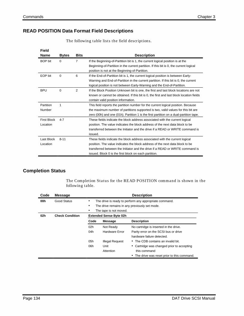
Commands Chapter 3
Page 134 DAT Drive SCSI Manual
READ POSITION Data Format Field Descriptions
The following table lists the field descriptions.
FieldName Bytes Bits Description
BOP bit 0 7 If the Beginning-of-Partition bit is 1, the current logical position is at the
Beginning-of-Partition in the current partition. If this bit is 0, the current logical
position is not at the Beginning-of-Partition.
EOP bit 0 6 If the End-of-Partition bit is 1, the current logical position is between Early-
Warning and End-of-Partition in the current partition. If this bit is 0, the current
logical position is not between Early-Warning and the End-of-Partition.
BPU 0 2 If the Block Position Unknown bit is one, the first and last block locations are not
known or cannot be obtained. If this bit is 0, the first and last block location fields
contain valid position information.
Partition
Number
1 This field reports the partition number for the current logical position. Because
the maximum number of partitions supported is two, valid values for this bit are
zero (00h) and one (01h). Partition 1 is the first partition on a dual-partition tape.
First Block
Location
4-7 These fields indicate the block address associated with the current logical
position. The value indicates the block address of the next data block to be
transferred between the Initiator and the drive if a READ or WRITE command is
issued.
Last Block
Location
8-11 These fields indicate the block address associated with the current logical
position. The value indicates the block address of the next data block to be
transferred between the Initiator and the drive if a READ or WRITE command is
issued. Block 0 is the first block on each partition.
Completion Status
The Completion Status for the READ POSITION command is shown in thefollowing table.
Code Message Description
00h Good Status • The drive is ready to perform any appropriate command.
• The drive remains in any previously set mode.
• The tape is not moved.
02h Check Condition Extended Sense Byte 02h
Code Message Description
02h Not Ready No cartridge is inserted in the drive.
04h Hardware Error Parity error on the SCSI bus or drive
hardware failure detected.
05h Illegal Request • The CDB contains an invalid bit.
06h Unit • Cartridge was changed prior to accepting
Attention this command
• The drive was reset prior to this command.
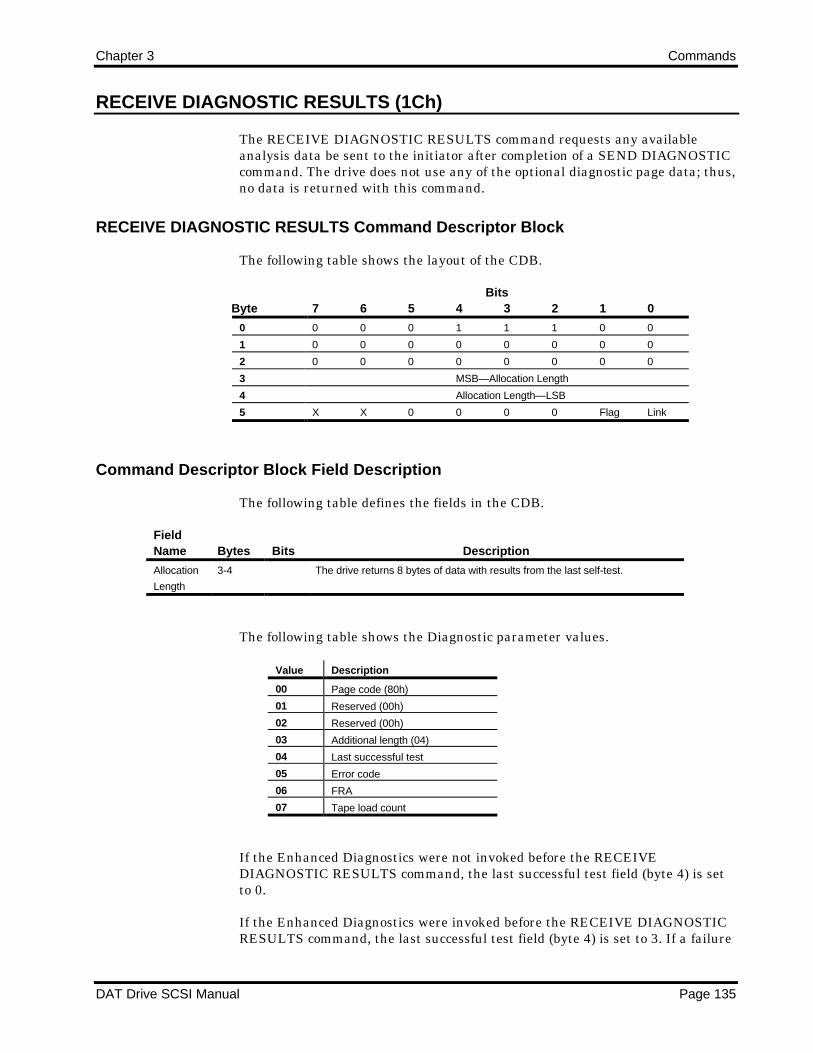
Chapter 3 Commands
DAT Drive SCSI Manual Page 135
RECEIVE DIAGNOSTIC RESULTS (1Ch)
The RECEIVE DIAGNOSTIC RESULTS command requests any availableanalysis data be sent to the initiator after completion of a SEND DIAGNOSTICcommand. The drive does not use any of the optional diagnostic page data; thus,no data is returned with this command.
RECEIVE DIAGNOSTIC RESULTS Command Descriptor Block
The following table shows the layout of the CDB.
ByteBits
7 6 5 4 3 2 1 0
0 0 0 0 1 1 1 0 0
1 0 0 0 0 0 0 0 0
2 0 0 0 0 0 0 0 0
3 MSB—Allocation Length
4 Allocation Length—LSB
5 X X 0 0 0 0 Flag Link
Command Descriptor Block Field Description
The following table defines the fields in the CDB.
FieldName Bytes Bits Description
Allocation
Length
3-4 The drive returns 8 bytes of data with results from the last self-test.
The following table shows the Diagnostic parameter values.
Value Description
00 Page code (80h)
01 Reserved (00h)
02 Reserved (00h)
03 Additional length (04)
04 Last successful test
05 Error code
06 FRA
07 Tape load count
If the Enhanced Diagnostics were not invoked before the RECEIVEDIAGNOSTIC RESULTS command, the last successful test field (byte 4) is setto 0.
If the Enhanced Diagnostics were invoked before the RECEIVE DIAGNOSTICRESULTS command, the last successful test field (byte 4) is set to 3. If a failure

Commands Chapter 3
Page 136 DAT Drive SCSI Manual
occurred during one of the tests, byte 4 is set to the previous test that passedsuccessfully.
If no errors occurred during the Enhanced Diagnostics or the EnhancedDiagnostics were not invoked, the Error code field (byte 5) is set to 0.
If an error occurred during one of the tests, byte 5 is set as follows:
Error Code Description
10 C1 error threshold exceeded
24 Position lost
25 Requested position not found
2A Write failure, excessive rewrites
2D Capstan error
2E Cylinder error
2F Reel error
3D Mechanism error
32 Tape jam
36 Dew error
The FRA field (byte 6) of the Diagnostics data is set as follows:
FRA Indication
0 No errors
1 Drive errors
2 Faulty media
3 Power supply or cable problems
4 Cleaning required
Completion Status
The Completion Status for the RECEIVE DIAGNOSTIC RESULTS command isshown in the following table.
Code Message Description
00h Good Status • The drive is ready to perform any appropriate command.
• The drive remains in any previously set mode.
• The tape position is not changed.
02h Check Condition Extended Sense Byte 02h
Code Message Description
04h Hardware Error Drive hardware failure detected.
05h Illegal Request • The CDB contains an invalid bit.
06h Unit • Cartridge was changed prior to accepting
Attention this command
• The drive was reset prior to this command.
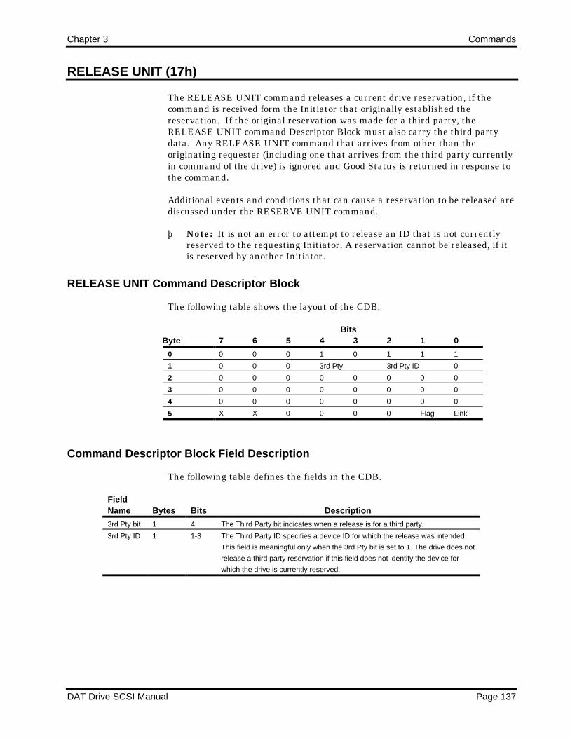
Chapter 3 Commands
DAT Drive SCSI Manual Page 137
RELEASE UNIT (17h)
The RELEASE UNIT command releases a current drive reservation, if thecommand is received form the Initiator that originally established thereservation. If the original reservation was made for a third party, theRELEASE UNIT command Descriptor Block must also carry the third partydata. Any RELEASE UNIT command that arrives from other than theoriginating requester (including one that arrives from the third party currentlyin command of the drive) is ignored and Good Status is returned in response tothe command.
Additional events and conditions that can cause a reservation to be released arediscussed under the RESERVE UNIT command.
þ Note: It is not an error to attempt to release an ID that is not currentlyreserved to the requesting Initiator. A reservation cannot be released, if itis reserved by another Initiator.
RELEASE UNIT Command Descriptor Block
The following table shows the layout of the CDB.
ByteBits
7 6 5 4 3 2 1 0
0 0 0 0 1 0 1 1 1
1 0 0 0 3rd Pty 3rd Pty ID 0
2 0 0 0 0 0 0 0 0
3 0 0 0 0 0 0 0 0
4 0 0 0 0 0 0 0 0
5 X X 0 0 0 0 Flag Link
Command Descriptor Block Field Description
The following table defines the fields in the CDB.
FieldName Bytes Bits Description
3rd Pty bit 1 4 The Third Party bit indicates when a release is for a third party.
3rd Pty ID 1 1-3 The Third Party ID specifies a device ID for which the release was intended.
This field is meaningful only when the 3rd Pty bit is set to 1. The drive does not
release a third party reservation if this field does not identify the device for
which the drive is currently reserved.
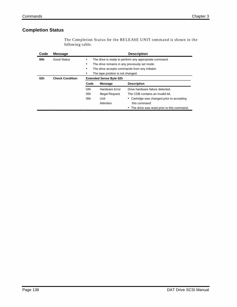
Commands Chapter 3
Page 138 DAT Drive SCSI Manual
Completion Status
The Completion Status for the RELEASE UNIT command is shown in thefollowing table.
Code Message Description
00h Good Status • The drive is ready to perform any appropriate command.
• The drive remains in any previously set mode.
• The drive accepts commands from any Initiator.
• The tape position is not changed.
02h Check Condition Extended Sense Byte 02h
Code Message Description
04h Hardware Error Drive hardware failure detected.
05h Illegal Request The CDB contains an invalid bit.
06h Unit • Cartridge was changed prior to accepting
Attention this command
• The drive was reset prior to this command.

Chapter 3 Commands
DAT Drive SCSI Manual Page 139
REQUEST BLOCK ADDRESS (02h)
The REQUEST BLOCK ADDRESS command requests the drive to transfer thecurrent block address to the Initiator. This command returns the block addressnumber on tape.
REQUEST BLOCK ADDRESS Command Descriptor Block
The following table shows the layout of the CDB.
ByteBits
7 6 5 4 3 2 1 0
0 0 0 0 0 0 0 1 0
1 0 0 0 0 0 0 0 0
2 0 0 0 0 0 0 0 0
3 0 0 0 0 0 0 0 0
4 Allocation Length
5 X X 0 0 0 0 Flag Link
Command Descriptor Block Field Description
The following table defines the fields in the CDB.
FieldName Bytes Bits Description
Allocation
Length
4 Set to 0, the default Transfer Length (3) is used. When nonzero, the number of
bytes specified in the Allocation Length (to a maximum of 3 bytes) is
transferred.
REQUEST BLOCK ADDRESS Address Data Format
The following table provides the address data format.
ByteBits
7 6 5 4 3 2 1 0
0 MSB—Block Address
1 Block Address
2 Block Address—LSB
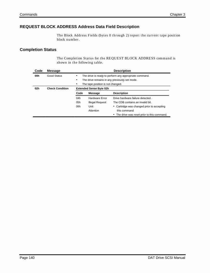
Commands Chapter 3
Page 140 DAT Drive SCSI Manual
REQUEST BLOCK ADDRESS Address Data Field Description
The Block Address Fields (bytes 0 through 2) report the current tape positionblock number.
Completion Status
The Completion Status for the REQUEST BLOCK ADDRESS command isshown in the following table.
Code Message Description
00h Good Status • The drive is ready to perform any appropriate command.
• The drive remains in any previously set mode.
• The tape position is not changed.
02h Check Condition Extended Sense Byte 02h
Code Message Description
04h Hardware Error Drive hardware failure detected.
05h Illegal Request The CDB contains an invalid bit.
06h Unit • Cartridge was changed prior to accepting
Attention this command
• The drive was reset prior to this command.

Chapter 3 Commands
DAT Drive SCSI Manual Page 141
REQUEST SENSE (03h)
The REQUEST SENSE command causes the drive to transfer status data to theInitiator pertaining to the last command.
REQUEST SENSE Command Descriptor Block
The following table shows the layout of the CDB.
ByteBits
7 6 5 4 3 2 1 0
0 0 0 0 0 0 0 1 1
1 0 0 0 0 0 0 0 0
2 0 0 0 0 0 0 0 0
3 0 0 0 0 0 0 0 0
4 Allocation Length
5 X X 0 0 0 0 Flag Link
Sense Data is updated with each command; therefore, the sense data onlyreports the status of the immediately previous command. If a Check Conditionstatus results, a REQUEST SENSE command should be issued to recover theinformation form the Sense Data.
The REQUEST SENSE command returns Check Condition status only if a fatalerror occurs during execution of the REQUEST SENSE command. If nonfatalerrors occur during the REQUEST SENSE execution, Good Status is returned.Sense Data may be invalid following a fatal error on a REQUEST SENSEcommand.
Sense Data Format
The following table shows the format for the sense data.

Commands Chapter 3
Page 142 DAT Drive SCSI Manual
ByteBits
7 6 5 4 3 2 1 0
0 Valid 1 1 1 0 0 0 0
1 0 0 0 0 0 0 0 0
2 FM EOM ILI 0 | Sense Key
3 MSB—Residual Length (0)
4 Residual Length (0)
5 Residual Length (0)
6 Residual Length—LSB (0)
7 Additional Sense Length
8 0 0 0 0 0 0 0 0
9 0 0 0 0 0 0 0 0
10 0 0 0 0 0 0 0 0
11 0 0 0 0 0 0 0 0
12 Additional Sense Code
13 Additional Sense Code Qualifier
14 0 0 0 0 0 0 0 0
15 SKSV C/D 0 0 BPV | Bit Pointer
16 MSB—Field Pointer
17 Field Pointer—LSB
18 0 0 0 0 0 0 0
Sense Data Field Descriptions
The Sense Data field descriptions are shown in the following table.
FieldName Bytes Bits Description
Valid bit 0 7 The Valid Bit indicates that the Residual Length field (Bytes 3 to 6) is defined. If the
Valid Bit is 1, Residual Length is the requested length minus the actual length in
blocks or bytes. For example:
If: Write Transfer Length = 1000 blocks
Residual Length = 896 blocks
Blocks transferred to drive = 192
Then: Transfer Length – Residual Length = Data written to tape
1000–896 = 108
And: Blocks transferred to drive – Data to tape = Data trapped in buffer
192 –108 = 84
FM bit 2 7 The FM bit indicates that the current command has read a Filemark or a save
setmark (if the RSMK bit is set).
EOM bit 2 6 The EOM bit indicates one of the following:
• Early-warning has been reached or passed in the forward direction.
• The command could not be completed because BOT was encountered in a
space reverse command.

Chapter 3 Commands
DAT Drive SCSI Manual Page 143
FieldName Bytes Bits Description
Incorrect
Length
Indicator (ILI
2 5 If this bit is 1, a block was read that has a length different than that which is
specified.
Sense Key 2 0-3 This field indicates the status of the last command and provides a generic error
category.
Residual
Length
3-6 See Valid bit.
Additional
Sense
Length
7 A number greater that zero in this field indicates that bytes 8 through N contain
information.
Additional
Sense Code
12 This field provides further detail for the current Sense Key.
Additional
Sense Code
Qualifier
13 This field provides further detail for the current Additional Sense Code.
SKSV bit 15 7 If the Sense Key Specific Valid (SKSV) bit is set (1), bytes 15-17 may be used to
determine the first illegal parameter that caused an Illegal Request sense key (as
defined below).
The following table lists the vendor unique SKSV reported by the drive when the
most significant bit of byte 15 si zero.
C/D bit 15 6 If the Command/Data (C/D) bit is set (1), the illegal parameter is in the CDB.
Otherwise, it is in the parameters sent in the Data-Out Phase.
BPV bit 15 3 When the Bit Pointer Valid (BPV) bit is set (1), the Bit Pointer field indicates the bit
field in error.
Bit Pointer 15 0-2 This field points to the most significant bit of the field in error.
Field Pointer 16-17 This field points to the most significant byte of the field in error. Bytes are numbered
starting from 0.
When a Log Exceptin is generated, bytes 16 and 17 indicate the MSB and LSB of
the Log Parameter code that caused the Log Exception. Byte 15 indicates the
affected page that caused the Log Exception.
The following table lists the vendor unique SKSV codes referenced in the tableabove.
Byte15 Definition
02h Log page 2 exception error.
03h Log page 3 exception error.
1Dh Error during timeout flush.
21h Tape encountered end of data.
22h Tape encountered end of tape.
23h Tape encountered beginning of tape.
24h Tape position has been lost.
25h Tape cannot find requested position.

Commands Chapter 3
Page 144 DAT Drive SCSI Manual
Byte
15 Definition
26h Unable to write additional data to tape.
27h Cartridge is write-protected.
28h Tape is not formatted.
29h Cartridge is not in drive.
2Ah Write failure.
2Bh Cartridge did not load properly.
2Ch Dartridge did not unload properly.
2Dh Error occurred with capstan servo.
2Eh Error occurred with tape cylinder.
2Fh Error occurred with tape reel.
30h An unknown mechanical error occurred.
31h The tape is cut.
32h The tape is jammed.
33h Error occurred in adjusting AGD.
34h Internal tape process error occurred.
35h Loader failure.
36h Dew error.
37h Invalid tape status.
38h Invalid control mode.
39h Drive error.
3Ah SDA search failed.
3Bh Tape erase failed.
3Ch Invalid Append AFC.
3Dh Missed SP3 interrupt.
3Eh Head clog write failure.
3Fh head clog read/search failure.
43h Unrecoverable read error occurred.
45h Cannot read medium, incompatible format.
46h Medium format is corrupted.
47h Bad entity header.
50h SPACE command logic error occurred.
51h Start of record not found during SPACE command.
52h Tape process returns incorrect groups during SPACE>
53h Compress data format corruption.
54h Block Access Table corruption during reading.
55h Block Access Table corruption during space.
60h Compression hardware fault occurred.
61h Port A parity error occurred.
62h Port B parity error occurred.

Chapter 3 Commands
DAT Drive SCSI Manual Page 145
Byte
15 Definition
70h Error occurred during compression.
71h Port B control problem occurred.
72h Compression LSI pause problem occurred.
73h Error occurred druing buffer swap.
74h Compression chip is not paused when expected.
75h FIFO is not empty when expected.
76h Compression chip not flushed when expected.
C0 Illegal LUN in the CDB
Priority and Definition of Sense Keys
The following table shows the priority and definition of the sense keys.
Key Message Definition
00h No Sense The Check Condition occurred in conjunction with detection of FM, EOT, or ILI, or
status was not available.
01h Recovered
Error
The Log Sense counter reached its maximum value and the RLEC bit is set.
02h Not Ready The drive is not ready to accept tape access commands. Operator intervention may
be required to correct this condition, or the drive may be coming ready.
03h Medium
Error
The command terminated with a nonrecoverable error that was probably caused by a
flaw in the medium or an error in the recorded data.
04h Hardware
Error
The drive detected a nonrecoverable hardware failure (parity, etc.) while performing
the command. Until the cartridge is ejected or a reset is received, the drive continues
to return this sense key to any tape motion command.
05h Illegal
Request
The CDB or command parameters contained an illegal parameter.
06h Unit
Attention
One of the following actions occurred: the cartridge was changed; the drive was
reset; the operational mode was changed; a Log Exception occurred; or the firmware
was changed.
07h Data Protect The cartridge is write-protected; the operation was not performed.
08h Blank Check A no-data condition was encountered on the tape, or the wrong data format was
encountered on tape.
0Bh Aborted
Command
The drive aborted the command. This key is returned if a bus parity error is detected.
The Initiator may be able to recover by trying the command again.
ODh Volume
Overflow
The drive reached the physical EOT, and write data remains in the buffer.
0Eh Miscompare The source data did not match the tape data during a VERIFY command.
Additional Sense Code and Code Qualifier
Additional sense codes and code qualifiers are returned in the REQUESTSENSE data in bytes 12 and 13. These byte codes are loaded whenever a CheckCondition is returned for any SCSI CDB. The purpose of the codes is to furtherdefine the cause of an error represented in the REQUEST SENSE Data SenseKey.

Commands Chapter 3
Page 146 DAT Drive SCSI Manual
The following table lists the additional sense code and code qualifiers.
Byte
2 12 13 Definition
0 NO SENSE
00 00 No additional sense data available.
00 01 Filemark detected.
00 02 End of tape or partition detected.
00 03 Setmark detected.
00 04 Beginning of partition or media.
1 RECOVERED ERROR
18 01 Recovered data with error condition and retries applied.
37 00 Rounded parameter.
5B 00 Log exception.
5B 02 Log counter at maximum
2 NOT READY
04 01 Logical unit is in process of becoming ready.
04 03 Logical unit not ready, manual intervention required
30 00 Incompatible medium installed.
30 03 Cleaning cartridge installed.
30 04 Diagnostic cartridge installed.
3A 00 Cartridge or magazine not present.
53 00 Cartridge load/eject failure.
5A 91 Eject button pushed.
3 MEDIUM ERROR
00 02 End of tape or partition detected
03 02 Excessive write errors.
0C 00 Write error during compression.
11 00 Unrecovered read error.
30 00 Bad entity header.
30 01 Cannot read tape, unknown format.
30 02 Cannot read tape, incompatible format.
30 11 Entity header wrong length.
30 12 Reserve byte not in entity header.
30 13 Bad algorithm byte in entity header.
30 C3 Compressed data format corruption.
30 C4 Block Access Table corruption during reading.
30 C5 Block Access Table corruption during space.
31 00 Tape format corrupted.
3B 00 Sequential positioning error.
3B 01 Tape position error at BOT.
3B 08 Lost tape position.
44 B3 Gain adjustment failure.
70 xx Decompression exception where xx specifies the illegal
algorithm

Chapter 3 Commands
DAT Drive SCSI Manual Page 147
Byte
2 12 13 Definition
4 HARDWARE ERROR
00 00 SPACE command logic error.
15 01 Mechanical positioning error.
20 00 Receive data DMA length error.
21 00 Send data DMA length error.
40 80 Diagnostic failed unknown test.
40 81 Diagnostic failed PROM Checksum test.
40 82 Diagnostic failed RAM test.
40 83 Diagnotic failed Memory Controller test.
40 84 Diagnostic failed Counter/Timer test.
40 85 Diagnostic failed SCSI LSI test.
40 86 Diagnostic failed ECC processor test.
40 87 Diagnostic failed Drive LSI test.
40 88 Diagnostic failed Compression LSI test.
40 89 Diagnostic failed EEPROM test
40 90 Tape read/write test failed.
44 00 Internal failure.
44 01 Internal failure: invalid completion code.
44 02 Internal failure: ISR failure.
44 80 Compression hardware fault.
44 81 Port A parity error.
44 82 Port B parity error.
44 90 Error during compression.
44 91 Port B control problem.
44 92 Compression LSI pause problem.
44 93 Error during buffer swap.
44 94 Compression chip not paused when expected.
44 95 FIFO not empty when expected.
44 96 Compression chip not flushed when expected.
44 9A Timeout during background operation.
44 AD Capstan servo error.
44 AE Tape cylinder error.
44 AF Tape reel error.
44 B0 Unknown mechanical error.
44 B1 The tape is cut.
44 B2 The tape is jammed.
44 B4 Tape process internal error.
44 B7 Internal error: invalid tape status.
44 B8 Internal error: invalid control mode.
44 B9 Internal error: drive error.
44 BA Internal error: SDA search failed.
44 BB Internal error: tape erase failed.
44 BC Internal error: invalid Append AFC.
44 BD Internal error: missed SP3 interrupt.

Commands Chapter 3
Page 148 DAT Drive SCSI Manual
Byte
2 12 13 Definition
44 C0 Magazine scanning to 1st detectable slot failed during
initialization (Autoloader only).
44 C1 Magazine positioning from one slot to next failed during
initializationAutoloader only).
44 C2 Magazine ejection failure (Autoloader only).
44 C3 Upward magazine movement failure (Autoloader only).
44 C4 Downward magazine movement failure (Autoloader only).
44 C5 Cartridge could not successfully be inserted (Autoloader
only).
44 C6 Cartridge insertion rollers could not engage (Autoloader
only).
44 C7 Cartridge insertion rollers could not disengage (Autoloader
only).
44 C8 Cartridge ejection failure (Autoloader only).
44 C9 Cartridge rollers could not engage during ejection (Autoloader
only).
44 CA Cartridge rollers could not disengage during ejection
(Autoloader only).
44 CB Drawer closing failure (Autoloader only).
44 CC Drawer opening failure (Autoloader only).
44 CD Magazine could not initialize to a known state after power-up
(Autoloader only).
45 00 Select or reselect failure.
46 00 Unsuccessful soft reset.
4B 00 Data Phase error.
51 00 Erase failure.
52 00 Cartridge fault.
53 00 Tape load failure
53 01 Unload tape failure.
82 80 Dew sensor
5 ILLEGAL REQUEST
1A 00 Invalid parameter list length.
20 00 Invalid CDB operation code.
21 01 Invalid element address.
24 00 Invalid field in CDB.
25 00 Logical unit not supported.
26 00 Invalid field in the parameter list.
26 01 Parameter not supported.
26 02 Parameter value invalid.
26 03 Threshold parameters not supported.
39 00 Saved bit not supported.
3A 00 Cartridge or magazine not present
3B 0D Destination element full.
3B 0E Source element empty.
3D 00 Invalid bits in Identify message.

Chapter 3 Commands
DAT Drive SCSI Manual Page 149
Byte
2 13 14 Definition
6 UNIT ATTENTION
28 00 Not ready to ready transition (cartridge or magazine change).
29 00 Power on or reset.
2A 01 Mode parameters changed.
5A 01 Cartridge was changed.
5B 01 Threshold condition met.
7 DATA PROTECT
27 00 Write protected.
30 00 Nn-MRS media
8 BLANK CHECK
00 05 End of data (EOD) detected.
30 01 Cannot read tape, unrecorded or unknown format.
B ABORTED COMMAND
1B 00 Host did not respond to SDTN message.
43 00 Message error.
45 00 Select or reselect failure.
47 00 SCSI parity error detected.
48 00 Initiator-detected error message received.
49 00 Invalid message error.
4A 00 Command Phase error.
4E 00 Reconnect abort error
53 00 Cartridge load/eject failure.
5A 01 Cartridge ejected.
D VOLUME OVERFLOW
00 02 End of partition/tape detected.
E MISCOMPARE
Autoloader Error Codes
The following table lists the error codes that might be displayed in the LEDpanel of the Autoloader.
(1) Display and LED Related
6 Invalid display parameter
(2) Magazine, Cartridge, and Drawer Related
2 Busy
3 Magazine not inserted
4 Magazine not initialized
5 Invalid slot number
6 Cartridge inserted in drive (or) invalid display parameter (see above)
7 Cartridge not inserted in slot (during insertion)
8 No cartridge in drive (during cartridge eject)
9 Cartridge inserted in slot (during cartridge eject)
F Hardware error

Commands Chapter 3
Page 150 DAT Drive SCSI Manual
10 Magazine initialize error (between START and 1st SLOT)
11 Magazine initialize error (between 1st SLOT and END SLOT).
b2 Drawer closed mag. init. error (between START and END SLOT)
b3 Drawer closed mag. init. error (between END SLOT and 2nd positioning)
20 Magazine eject error
30 Magazine upward movement error
31 Magazine downward movement error
40 Cartridge insert error
41 Cartridge insert clamp ON error
42 Cartridge insert clamp OFF error
50 Cartridge eject error
51 Cartridge eject clamp ON error
52 Cartridge eject clamp OFF error
60 Drawer close error
61 Drawer open error
70 Magazine lost (reset request)
a0 Stop by STOP command
f2 Drawer open error at power up. When drawer neither OPEN nor CLOSED at
powerup, the Autoloader firmware tries to open the drawer. If OPEN condition is not
reached wihtin 8 seconds, the f2 error is displayed.
Completion Status
The Completion Status for the REQUEST SENSE command is shown in thefollowing table.
Code Message Description
00h Good Status • The drive is ready to perform any appropriate command.
• The drive remains in any previously set mode.
• The tape position is not changed.
02h Check Condition Extended Sense Byte 02h
Code Message Description
04h Hardware Error Drive hardware failure detected.
05h Illegal Request The CDB contains an invalid bit.

Chapter 3 Commands
DAT Drive SCSI Manual Page 151
RESERVE UNIT (16h)
The RESERVE UNIT command reserves the drive for exclusive use of therequesting Initiator or for the exclusive use of third party specified SCSI device.
The drive reservation once established, remains in effect until occurrence of oneof the following:
Another RESERVE UNIT command arrives from the same Initiator thatrequested the current reservation (for itself or for a third party). The newreservation supersedes the current one and may be the same as the currentone. Redundant use of the command is not considered an error.
ARELEASE UNIT command arrives from the same Initiator that requestedthe current reservation. The drive returns to unreserved mode.
A Bus Device Reset Message arrives from any Initiator.
A Reset condition occurs.
Firmware is updated.
When the drive is reserved, it returns Reservation Conflict Status in responseto any and all commands received from excluded Initiators. An exception tothis is in response to the RELEASE UNIT command and in response to asubsequent RESERVE UNIT command from the original reservation requester.Also, see the RELEASE UNIT command. In addition, INQUIRY, REQUESTSENSE, and PREVENT MEDIUM REMOVAL commands will be accepted fromany initiator.
RESERVE UNIT Command Descriptor Block
The following table shows the layout of the CDB.
ByteBits
7 6 5 4 3 2 1 0
0 0 0 0 1 0 1 1 1
1 0 0 0 3rd Pty | 3rd Pty ID 0
2 0 0 0 0 0 0 0 0
3 0 0 0 0 0 0 0 0
4 0 0 0 0 0 0 0 0
5 X X 0 0 0 0 Flag Link

Commands Chapter 3
Page 152 DAT Drive SCSI Manual
Command Descriptor Block Field Description
The following table defines the fields in the CDB.
FieldName Bytes Bits Description
3rd Pty bit 1 4 The Third Party bit indicates whether or not the reservation is for a third party.
3rd Pty ID 1 1-3 The Third Party ID specifies a Initiator ID for which the release was intended.
This field is meaningful only when the 3rd Pty bit is set to 1. The drive does not
release a third party reservation if this field does not identify the Initiator
currently in control of the drive.
Completion Status
The Completion Status for the RESERVE UNIT command is shown in thefollowing table.
Code Message Description
00h Good Status • The drive is ready to perform any appropriate command.
• The drive remains in any previously set mode.
• The drive is reserved for the use of the specified ID.
• The tape position is not changed.
02h Check Condition Extended Sense Byte 02h
Code Message Description
04h Hardware Error Parity error on the SCSI bus or drive
hardware failure detected.
05h Illegal Request The CDB contains an invalid bit.
06h Unit • Cartridge was changed prior to accepting
Attention this command
• The drive was reset prior to this command.
18h Reservation Conflict The drive is reserved for another initiator.
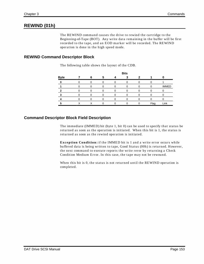
Chapter 3 Commands
DAT Drive SCSI Manual Page 153
REWIND (01h)
The REWIND command causes the drive to rewind the cartridge to theBeginning-of-Tape (BOT). Any write data remaining in the buffer will be firstrecorded to the tape, and an EOD marker will be recorded. The REWINDoperation is done in the high speed mode.
REWIND Command Descriptor Block
The following table shows the layout of the CDB.
ByteBits
7 6 5 4 3 2 1 0
0 0 0 0 0 0 0 0 1
1 0 0 0 0 0 0 0 IMMED
2 0 0 0 0 0 0 0 0
3 0 0 0 0 0 0 0 0
4 0 0 0 0 0 0 0 0
5 X X 0 0 0 0 Flag Link
Command Descriptor Block Field Description
The immediate (IMMED) bit (byte 1, bit 0) can be used to specify that status bereturned as soon as the operation is initiated. When this bit is 1, the status isreturned as soon as the rewind operation is initiated.
Exception Condition: if the IMMED bit is 1 and a write error occurs whilebuffered data is being written to tape, Good Status (00h) is returned. However,the next command to execute reports the write reror by returning a CheckCondition Medium Error. In this case, the tape may not be rewound.
When this bit is 0, the status is not returned until the REWIND operation iscompleted.

Commands Chapter 3
Page 154 DAT Drive SCSI Manual
Completion Status
The Completion Status for the REWIND command is shown in the followingtable.
Code Message Description
00h Good Status • The drive is ready to perform any appropriate command.
• The drive remains in any previously set mode.
• The tape position is BOT (if not IMM).
02h Check Condition Extended Sense Byte 02h
Code Message Description
02h Not Ready No cartridge is inserted in the drive, or the
cartridge is being positioned to BOT.
03h Medium Error See previous Exception Condition.
04h Hardware Error Drive hardware failure detected.
05h Illegal Request • The CDB contains an invalid bit.
• The Link bit and IMMED bit are both set
to 1.
06h Unit • Cartridge was changed prior to accepting
Attention this command
• The drive was reset prior to this command.
08h Busy An immediate command is in progress.

Chapter 3 Commands
DAT Drive SCSI Manual Page 155
SEEK BLOCK (0Ch)
The SEEK BLOCK command is used to position the tape to the specified blockaddress in the current partition. No data is transferred. SEEK BLOCKpositions the tape to block locations greater or less than the current blockposition. Positioning is done with a high speed search and does not require asequential read for the requested block.
The Initiator may obtain block addresses through the REQUEST BLOCKADDRESS command as part of its tape write procedures. The block addressescan, in turn, be recorded in a user-defined directory.
When there is no exception condition during a SEEK BLOCK command, thetape is logically positioned before the block specified in the block address. Thefirst data block on tape is block 1; therefore, a zero in the block address isconsidered an error.
SEEK BLOCK Command Descriptor Block
The following table shows the layout of the CDB.
ByteBits
7 6 5 4 3 2 1 0
0 0 0 0 0 1 1 0 0
1 0 0 0 0 0 0 0 IMMED
2 MSB—Block Address
3 Block Address
4 Block Address—LSB
5 X X 0 0 0 0 Flag Link
Command Descriptor Block Field Description
The following table provides descriptions of the CDB fields.
FieldName Bytes Bits Description
IMMED 1 0 If this bit is 1, the status is returned as soon as the operation is initiated. If
this bit is 0, the status is returned after the tape is positioned at the specified
block.
Block
Address
2-4 These fields specify the address of the block to which the tape is to be
positioned.

Commands Chapter 3
Page 156 DAT Drive SCSI Manual
Completion Status
The Completion Status for the SEEK BLOCK command is shown in thefollowing table.
Code Message Description
00h Good Status • The drive is ready to perform any appropriate command.
• The drive remains in any previously set mode.
• The tape is positioned before the requested block.
02h Check Condition Extended Sense Byte 02h
Code Message Description
02h Not Ready No cartridge is inserted in the drive.
03h Media Error Unrecoverable data error encountered.
04h Hardware Error Drive hardware failure detected.
05h Illegal Request • The CDB contains an invalid bit.
• Block count of zero was issued.
06h Unit • Cartridge was changed prior to accepting
Attention this command
• The drive was reset prior to this command.
08h Blank Check • EOD was encountered.
• The requested block number is greater than
the last block written on tape.

Chapter 3 Commands
DAT Drive SCSI Manual Page 157
SEND DIAGNOSTIC (1Dh)
The SEND DIAGNOSTIC command causes the drive to perform diagnostic self-tests. The tests are part of the drive-resident firmware. If the Off-Line bit is 0,no data is transferred between the drive and the Initiator during this command.the diagnostics take about 4 seconds to complete.
If the Off-line bit is 1, a tape read/write test is performed. These tests can takeup to 60 seconds to complete. All data on the inserted cartridge is lost.
Good Status is returned if the tests are successful; otherwise, the tailed test isindicated in the REQUEST SENSE data.
SEND DIAGNOSTIC Command Descriptor Block
The following table shows the layout of the Command Descriptor Block.
ByteBits
7 6 5 4 3 2 1 0
0 0 0 0 1 1 1 0 1
1 0 0 0 0 0 Self-Test DEVOF Off-Line
2 0 0 0 0 0 0 0 0
3 0 0 0 0 0 0 0 0
4 0 0 0 0 0 0 0 0
5 X X 0 0 0 0 Flag Link
The combinations of bits in byte 1 are defined as shown in the following table.
Self-TestBit 2
DEVOFBit 1
Off-LineBit 0
Description
1 0 0 Power-up self-test1 0 1 Read/write tests1 1 1 Enhanced diagnostics

Commands Chapter 3
Page 158 DAT Drive SCSI Manual
Completion Status
The Completion Status for the SEND DIAGNOSTIC command is shown in thefollowing table.
Code Message Description
00h Good Status • The drive is ready to perform any appropriate command.
• The drive remains in any previously set mode.
• The tape position is not changed.
02h Check Condition Extended Sense Byte 02h
Code Message Description
02h Not Ready No cartridge is inserted in the drive.
04h Hardware Error Drive hardware failure detected.
05h Illegal Request The CDB contains an invalid bit.
06h Unit • Cartridge was changed prior to accepting
Attention this command
• The drive was reset prior to this command.
NOTE: The amber drive LED flashes rapidly if a hardware fault is detected.

Chapter 3 Commands
DAT Drive SCSI Manual Page 159
SPACE (11h)
The SPACE command uses five methods to move the tape. This commandmoves the position:
Forward or backward a specified number of blocks.
Forward or backward a specified number of filemarks.
Forward or backward a specified number of setmarks.
Forward a specified number of sequential (contiguously grouped) filemarksor setmarks.
Forward to the end of recorded data.
If the target block or filemark is in the buffer of the drive, no tape motionresults. Otherwise, spacing is done at high search speed.
A file example is shown below.
Block 1 2 3 4 5 6 7 8 9 10 11 12 13
BOT Data Data Data Data F/M Data Data F/M Data Data F/M F/M F/M
Position 1 2 3
When SPACE Block count is 4 from BOT, SPACE positions the tape to theend of the 4th block (position #1).
When SPACE Sequential filemarks count is 2 from BOT, SPACE positionsthe tape to the end of the next occurrence of a double filemark (position# 2).
When SPACE filemarks count is 5 from BOT, SPACE positions the tape toposition #3.
SPACE Command Descriptor Block
The following table shows the layout of the Command Descriptor Block.
ByteBits
7 6 5 4 3 2 1 0
0 0 0 0 1 0 0 0 1
1 0 0 0 0 0 Code
2 MSB—Count
3 Count
4 Count—LSB
5 X X 0 0 0 0 Flag Link

Commands Chapter 3
Page 160 DAT Drive SCSI Manual
Command Descriptor Block Field Descriptions
The following table provides descriptions of the CDB fields.
FieldName Bytes Bits Description
Code 1 0-2 The Code Field designates the desired function as shown below:
Bits
2 1 0 Function
0 0 0 Space blocks
0 0 1 Space filemarks
0 1 0 Space sequential filemarks
0 1 1 Space to end of recorded data
1 0 0 Space setmarks
Count 2-4 This field specifies the number of blocks, filemarks, sequential filemarks, or
setmarks to space over. A zero value in the Count field causes no media
movement and is not considered an error.
Space-by-Count Functions
The Count field indicates both direction and distance within the currentpartition. A positive value N in the Count field moves the tape forward over Nblocks, filemarks, contiguous filemarks, or setmarks. A negative value -N (2'scomplement) in the Count field moves the tape backward over N blocks,filemarks, or setmarks. Zero in the count field causes no tape movement and isnot considered an error.
When there are no exception conditions during space functions, forward tapemotion ends on the EOT side of the last block, filemark, or setmark and reversemotion ends on the BOT side of the last block, filemark, or setmark.
If a filemark or setmark is encountered while spacing over blocks or asetmark is encountered while spacing filemarks, a Check Condition Statusis returned. The Sense FM bit is set unless a setmark is encountered andRSMK=0. The Sense Valid bit is set, indicating Residual Length is non-zero.
The Residual Length equals the difference in the requested count and theactual number of blocks spaced over not including the filemark or setmark.The tape is positioned on the logical EOT side of the filemark or setmark ifmovement was forward or on the logical BOT side of the filemark orsetmark if movement was reverse.
If EOD is encountered while spacing forward, Check Condition is returnedwith 08h Sense Key. Extended Sense Valid bit is set, indicating ResidualLength is nonzero.
If BOT is encountered while spacing in reverse, Check Condition isreturned with 40h Sense Key. Extended sense Valid bit is set, indicating anonzero Residual Length.

Chapter 3 Commands
DAT Drive SCSI Manual Page 161
If EOT is encountered while spacing forward, Check Condition is returnedwith 40h or 43h Sense Key. Extended Sense Valid bit is set, indicating anonzero Residual Length.
If an unrecoverable data error is encountered, Check Condition is returned,Extended Sense Key is set to Medium Error, and Extended Sense Valid bitis set, indicating Residual Length is nonzero.
Space by Position Functions
The Count field is not applicable in space-to-EOD functions.
In the space-to-EOD function, the tape is positioned such that a subsequentWRITE command appends data to the last recorded information on the tape.This positioning is done at high search speed.
The space-to-EOD function is useful in support of user-defined directorieslocated at the end of recorded data.
If physical EOT is encountered while spacing to end of data, CheckCondition Status is returned and Extended Sense is set to Medium Error.
If unrecoverable data error is encountered, Check Condition Status isreturned, Extended Sense Key is set to Medium Error, and Extended SenseValid bit is set, indicating Residual Length is non-zero.
Space and the RSMK Bit
A Report Setmark (RSMK) bit determines whether or not the drive recognizessetmarks during a SPACE operation. If the value of the RSMK bit is 1, thedrive recognizes and reports setmarks when searching for the target. If thevalue of the bit is 0, the drive ignores setmarks during execution of the SPACEcommand.
Assume that the data was written on the tape as shown in the following table.
Block 1 2 3 4 5 6 7 8 9 10 11 12 13 14BOT D S S S S S D D D D D D D cod
Position A B C D E F
Similar with the LOCATE command, if the RSMK bit is 0 when the SPACEcommand is issued, all the setmarks are logically grouped with its nearest DataBlock on its BOT side to form a single logical block. The following table showsthe logical blocks when the RSMK bit is set to 0. In the table, the data block inblock number 1 together with five setmarks in blocks number 12-6 areconsidered as one logical block.
Block 1 1 1 1 1 1 2 3 4 5 6 7 8 9BOT D S S S S S D D D D D D D cod

Commands Chapter 3
Page 162 DAT Drive SCSI Manual
If the RSMK bit is 1 in the CDB when the SPACE command is issued, then thesetmark is recognized and reported during execution of the SPACE operation.The following table show sthe logical blocks.
Block 1 2 3 4 5 6 7 8 9 10 11 12 13 14BOT D S S S S S D D D D D D D cod
Referring to the first table, the table below shows the tape position after eachSPACE command is complete.
SPACE X Blocks From RSMK bit Tape Position1 BOT ON B-7 EOD ON E1 BOT OFF E-7 EPD OFF E2 BOT ON C, chk cond res = 1-8 EOD ON D, chk cond res = -12 BOT OFF F-8 EOD OFF A
Completion Status
The Completion Status for the SPACE command is shown in the following table.
Code Message Description
00h Good Status • The drive is ready to perform any appropriate command.
• The drive remains in any previously set mode.
• The tape is positioned on the EOT side if space forward and on the BOT
side if space reverse.
02h Check Condition Extended Sense Byte 02h
Code Message Description
02h Not Ready No cartridge is inserted in the drive.
03h Media Error Unrecoverable data error encountered while
performing a SPACE command.
04h Hardware Error Drive hardware failure detected.
05h Illegal Request The CDB contains an invalid bit.
06h Unit • Cartridge was changed prior to accepting
Attention this command
• The drive was reset prior to this command.
08h Blank Check • EOD was encountered while executing a
SPACE forward.

Chapter 3 Commands
DAT Drive SCSI Manual Page 163
TEST UNIT READY (00h)
The TEST UNIT READY command tests for three conditions:
The drive is powered on.
A cartridge is inserted in the drive.
The drive is ready to accept a medium-access command.
If these three conditions are met, the drive returns Good Status.
This command does not access the medium or initiate a diagnostic routine.
TEST UNIT READY Command Descriptor Block
The following table shows the layout of the Command Descriptor Block.
ByteBits
7 6 5 4 3 2 1 0
0 0 0 0 0 0 0 0 0
1 0 0 0 0 0 0 0 0
2 0 0 0 0 0 0 0 0
3 0 0 0 0 0 0 0 0
4 0 0 0 0 0 0 0 0
5 X X 0 0 0 0 Flag Link
TEST UNIT READY Detailed Operation
The following text lists the sense keys plus the additional sense codes andqualifiers reported by the drive during various stages of loading and unlaodingcartridges. The format of the values is additional sense code/additional sensequalifier. BUSY means that the drive returns a status byte of 08. In all othercases, CHECK (02) is returned.
In the following table and text, NOT READY indicates a sensee key of 02, andUNIT ATTN indicates a sense key of 06.
Action First TUR ResponseResponse whileEjecting
Response after Tapeis Out
Press eject NOT READY 5A/01 NOT READY 04/03 NOT READY 3A/00UNLOAD command BUSY, IMMED=1 BUSY, IMMED=1 NOT READY 3A/00Insert, then eject UNIT ATTN 28/0- NOT READY 04/03 NOT READY 3A/00

Commands Chapter 3
Page 164 DAT Drive SCSI Manual
If a cartridge is in the drive at power up and a TEST UNIT READY command isissued before the tape is positioned at BOT, then the following responses occur:
First TUR ResponseResponse duringTape Loading
Response after Tapeis Out
UNIT ATTN 29/00 Busy UNIT ATTN 28/00
If a cartridge is in the drive at power up and no TEST UNIT READY commandis received until after the tape is positioned at BOT, then the followingresponses occur:
First TUR ResponseSubsequent TURResponse
UNIT ATTN 29/00 GOOD STATUS
Completion Status
The Completion Status for the TEST UNIT READY command is shown in thefollowing table.
Code Message Description
00h Good Status • The drive is ready to perform any appropriate command.
• The drive remains in any previously set mode.
• The tape is not moved.
02h Check Condition Extended Sense Byte 02h
Code Message Description
02h Not Ready No cartridge is inserted in the drive; an
immediate command execution is in progress;
or an UNLOAD command has been
executed. Bytes 12 and 13 of the Sense Data
indicate the type of not ready state.
04h Hardware Error Drive hardware failure detected.
05h Illegal Request The CDB contains an invalid bit.
06h Unit • Cartridge was changed prior to accepting
Attention this command
• The drive was reset prior to this command.
08h Busy Tape is being initialized after cartridge insertion,, or the drive is executing a
previous immediate command.

Chapter 3 Commands
DAT Drive SCSI Manual Page 165
VERIFY (13h)
The VERIFY command verifies one or more blocks of data beginning with thenext block from the tape unit.
The command terminates after the specified number of bytes or blocks areverified or when the drive encounters a filemark, the EOT, or an unrecoverableerror. On completion the medium is positioned after the last block verified orafter a filemark.
If a VERIFY with a zero verification length is issued, no data is verified, andthe current position on the tape does not change. This condition is notconsidered an error.
VERIFY Command Descriptor Block
The following table shows the layout of the Command Descriptor Block.
ByteBits
7 6 5 4 3 2 1 0
0 0 0 0 1 0 0 1 1
1 0 0 0 0 0 0 0 Fixed
2 MSB—Verify Length
3 Verify Length
4 Verify Length—LSB
5 X X 0 0 0 0 Flag Link
Command Descriptor Block Field Description
The following table defines the fields in the CDB.
FieldName Bytes Bits Description
Fixed
Block Size
bit
1 0 If this bit is 0, block is variable length. IF this bit is 1, blocks are fixed length.
Verify
Length
2-4 This field specifies the number of contiguous bytes or blocks to be verified in
fixed mode or the length of the variable block..
Data Transfers with the VERIFY Command
Comparison errors detected cause a Check Condition with the Sense Key set to0E hexadecimal, which indicates a miscompare. The residual byte or blockcount is reflected in the REQUEST SENSE data.
When the Fixed bit is set (1), the Verify Length specifies the number ofcontiguous blocks to be verified on the tape. When the Fixed bit is reset (0), theVerify Length specifies the number of bytes in the block to verify.

Commands Chapter 3
Page 166 DAT Drive SCSI Manual
The byte compare starts on a block boundary starting at the current tape blockposition.
Completion Status
The Completion Status for the VERIFY command is shown in the followingtable.
Code Message Description
00h Good Status • The drive is ready to perform any appropriate command.
• The drive remains in any previously set mode.
• The tape is positioned on the EOT side of the last block verified.
02h Check Condition Extended Sense Byte 02h
Code Message Description
02h Not Ready No cartridge is inserted in the drive.
03h Media Error Unrecoverable data error was encountered.
04h Hardware Error Drive hardware failure detected.
05h Illegal Request The CDB contains an invalid bit.
06h Unit • Cartridge was changed prior to accepting
Attention this command
• The drive was reset prior to this command.
08h Blank Check • End of recorded data was encountered.
0Eh Miscompare VERIFY data miscompare.

Chapter 3 Commands
DAT Drive SCSI Manual Page 167
WRITE (0Ah)
The WRITE command transfers one or more data blocks from the Initiator tothe drive. If the Transfer Length is zero, no data is transferred, and the currentposition of the tape is not changed. This condition is not considered an error.
WRITE Command Descriptor Block
The following table shows the layout of the Command Descriptor Block.
ByteBits
7 6 5 4 3 2 1 0
0 0 0 0 0 1 0 1 0
1 0 0 0 0 0 0 0 Fixed
2 MSB—Transfer Length
3 Transfer Length
4 Transfer Length—LSB
5 X X 0 0 0 0 Flag Link
The drive calculates the logical Early Warning. The Early Warning point iscalculated as greater than ten megabytes before the EOT. This ensures thatwhen Early Warning is encountered, enough space remains to successfullywrite any unwritten blocks up to ten megabytes.
At Early Warning, the drive completes the current block transfer andterminates the command with a Check Condition, EOM bit set, and Sense Keyequal to 0. If the SEW bit (in MODE SELECT Device Configuration Page) is set,the data in the buffer is then written to tape.
Subsequent WRITE commands complete with a Check Condition and the EOMbit set.
If writing the buffer to tape is unsuccesful because of EOT, a Volume Overflowis reported. The Residual count field in the Request Sense data reports theamount of data not transferred. Writing can continue in the Early Warningregion until EOT is encountered. Any WRITE command issued within EarlyWarning and successfully completed, finishes with a Check Condition and theEOM bit set.
If an error is encountered while writing, the Write Retry Count (in MODESELECT Read/Write Error Recovery Page) specifies the maximum number ofattempts to rewrite the data. If none of the rewrites area successful, the error isconsidered unrecoveralbe and reported as such. This situation may occur if thetape has severe damage. In this case, the green LED flashes rapidly.

Commands Chapter 3
Page 168 DAT Drive SCSI Manual
Command Descriptor Block Field Description
The following table defines the fields in the CDB.
FieldName Bytes Bits Description
Fixed
Block Size
bit
1 0 If this bit is 0, the transfer length contains the number of bytes in the block. IF
this bit is 1, blocks are of fixed size, as specified by the MODE SELECT Block
Descriptor..
Transfer
Length
2-4 0-7 These fields specify the number of bytes or blocks to be written at the current
tape position, if Fixed=0.
Completion Status
The Completion Status for the WRITE command is shown in the followingtable.
Code Message Description
00h Good Status • The SCSI data has been transferred to the data buffer.
• The drive remains in any previously set mode.
02h Check Condition Extended Sense Byte 02h
Code Message Description
02h Not Ready No cartridge is inserted in the drive.
03h Media Error Unrecoverable data error encountered.
Possibly bad cartridge.
04h Hardware Error Drive hardware failure detected.
05h Illegal Request The CDB contains an invalid bit.
06h Unit • Cartridge was changed prior to accepting
Attention this command
• The drive was reset prior to this command.
07h Write Protect The tape is write-protected; check the
cartridge before continuing.
0Dh Volume Overflow WRITE command completed with data in the
buffer because the end-of-partition was
encountered.

Chapter 3 Commands
DAT Drive SCSI Manual Page 169
WRITE DATA BUFFER (3Bh)
The WRITE DATA BUFFER command is used in conjunction with the READDATA BUFFER command as a diagnostic function for testing the data buffermemory of the drive and confirming the SCSI bus integrity. The medium is notaccessed during the execution of this command.
The WRITE DATA BUFFER command can also be used to download thecontroller firmware if the drive is equipped with flash EEPROM. Only firmwaresupplied by Seagate should be downloaded. Once the valid firmware isdownloaded to the buffer, the flash EEPROM is programmed. Then, within 30seconds, control is transferred to the new firmware and a power-on reset occurs.The drive is then ready to accept further commands.
WRITE DATA BUFFER Command Descriptor Block
The following table shows the layout of the Command Descriptor Block.
ByteBits
7 6 5 4 3 2 1 0
0 0 0 1 1 1 0 1 1
1 0 0 0 0 0 | MODE
2 MSB—ADRS/Buffer ID
3 ADRS
4 ADRS
5 ADRS—LSB
6 MSB—Byte Transfer Length
7 Byte Transfer Length
8 Byte Transfer Length—LSB
9 X X 0 0 0 0 Flag Link
ADRS is the buffer offset for Mode 2 and is the buffer address for Modes 4 and5.
Command Descriptor Block Field Descriptions
The following table provides descriptions of the CDB fields.
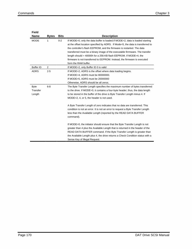
Commands Chapter 3
Page 170 DAT Drive SCSI Manual
FieldName Bytes Bits Description
MODE 1 0-2 If MODE=0, only the data buffer is loaded.If MODE=2, data is loaded starting
at the offset location specified by ADRS. If Mode=5, the data is transferred to
the controller's flash EEPROM, and the firmware is restarted. The data
transferred must be a binary image of the executable firrmware. The transfer
length should = 40000h for a 256-KB flash EEPROM. If MODE=4, the
firmware is not transferred to EEPROM. Instead, the firmware is executed
form the RAM buffer.
Buffer ID 2 If MODE=2, only Buffer ID 0 is valid
ADRS 2-5 If MODE=2, ADRS is the offset where data loading begins.
If MODE=4, ADRS must be 80000000.
If MODE=5, ADRS must be 20000000
Otherwise, ADRS should be all zeros.
Byte
Transfer
Length
6-8 The Byte Transfer Length specifies the maximum number of bytes transferred
to the drive. If MODE=0, it contains a four-byte header; thus, the data length
to be stored in the buffer of the drive is Byte Transfer Length minus 4. If
MODE=2, 4, or 5, the header is not used.
A Byte Transfer Length of zero indicates that no data are transferred. This
condition is not an error. It is not an error to request a Byte Transfer Length
less than the Available Length (reported by the READ DATA BUFFER
command).
If MODE=0, the initiator should ensure that the Byte Transfer Length is not
greater than 4 plus the Available Length that is returned in the header of the
READ DATA BUFFER command. If the Byte Transfer Length is greater than
the Available Length plus 4, the drive returns a Check Condition status with a
Sense Key of Illegal Request.
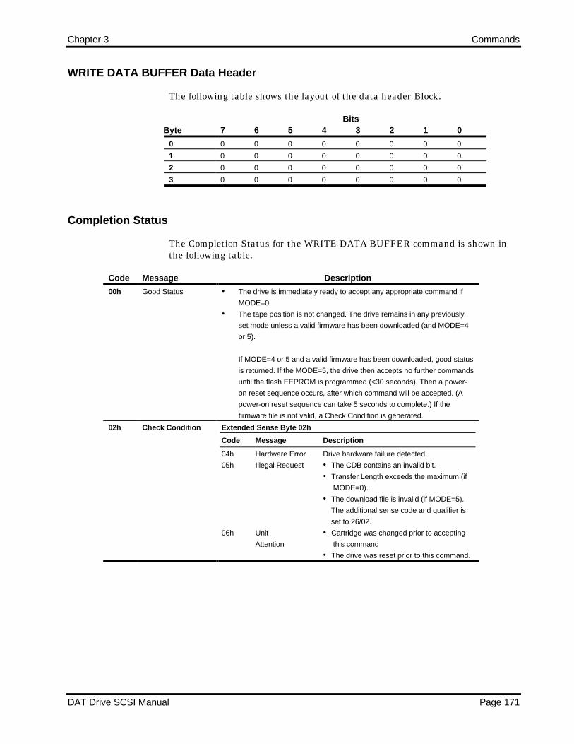
Chapter 3 Commands
DAT Drive SCSI Manual Page 171
WRITE DATA BUFFER Data Header
The following table shows the layout of the data header Block.
ByteBits
7 6 5 4 3 2 1 0
0 0 0 0 0 0 0 0 0
1 0 0 0 0 0 0 0 0
2 0 0 0 0 0 0 0 0
3 0 0 0 0 0 0 0 0
Completion Status
The Completion Status for the WRITE DATA BUFFER command is shown inthe following table.
Code Message Description
00h Good Status • The drive is immediately ready to accept any appropriate command if
MODE=0.
• The tape position is not changed. The drive remains in any previously
set mode unless a valid firmware has been downloaded (and MODE=4
or 5).
If MODE=4 or 5 and a valid firmware has been downloaded, good status
is returned. If the MODE=5, the drive then accepts no further commands
until the flash EEPROM is programmed (<30 seconds). Then a power-
on reset sequence occurs, after which command will be accepted. (A
power-on reset sequence can take 5 seconds to complete.) If the
firmware file is not valid, a Check Condition is generated.
02h Check Condition Extended Sense Byte 02h
Code Message Description
04h Hardware Error Drive hardware failure detected.
05h Illegal Request • The CDB contains an invalid bit.
• Transfer Length exceeds the maximum (if
MODE=0).
• The download file is invalid (if MODE=5).
The additional sense code and qualifier is
set to 26/02.
06h Unit • Cartridge was changed prior to accepting
Attention this command
• The drive was reset prior to this command.

Commands Chapter 3
Page 172 DAT Drive SCSI Manual
WRITE FILEMARKS (10h)
The WRITE FILEMARKS command causes the specified number of filemarks orsetmarks to be written to tape.
This command can be used to force all remaining buffered data blocks to bewritten to tape without appending filemarks by specifying zero filemarks. Whenzero filemarks are specified, the command does not return Good Status to theInitiator until all buffered data blocks and filemarks are written correctly onthe tape. Otherwise, status is returned immediately.
WRITE FILEMARKS Command Descriptor Block
The following table shows the layout of the Command Descriptor Block.
ByteBits
7 6 5 4 3 2 1 0
0 0 0 0 1 0 0 0 0
1 0 0 0 0 0 0 WSMK X
2 MSB—Number of Filemarks/Setmarks
3 Number of Filemarks/Setmarks
4 Number of Filemarks/Setmarks—LSB
5 X X 0 0 0 0 Flag Link
Command Descriptor Block Field Description
The following table defines the fields in the CDB.
FieldName Bytes Bits Description
WSMK bit 1 1 If this bit is 0, bytes 2-4 specify the number of filemarks to be written. If this bit
is 1, bytes 2-4 specify the number of setmarks to be written.
Number of
Filemarks/
Setmarks
2-4 0-7 These fields specify the number of filemarks or setmarks to record.

Chapter 3 Commands
DAT Drive SCSI Manual Page 173
Completion Status
The Completion Status for the WRITE FILEMARKS command is shown in thefollowing table.
Code Message Description
00h Good Status • The filemarks have been sent to the buffer.
• The drive remains in any previously set mode.
02h Check Condition Extended Sense Byte 02h
Code Message Description
02h Not Ready No cartridge is inserted in the drive.
03h Media Error Unrecoverable data error encountered.
Possibly bad cartridge.
04h Hardware Error Drive hardware failure detected.
05h Illegal Request The CDB contains an invalid bit.
06h Unit • Cartridge was changed prior to accepting
Attention this command
• The drive was reset prior to this command.
07h Write Protect The tape is write-protected; check the
cartridge before continuing.
0Dh Volume WRITE FILEMARK command completed with
Overflow data in the buffer because the end-of-
partition was encountered.

Commands Chapter 3
Page 174 DAT Drive SCSI Manual
Notes