Embed Size (px)
Citation preview

Product Manual
Seagate® Kinetic HDD
100764174Rev. BFebruary 2015
Standard model ST4000NK001

© 2015 Seagate Technology LLC. All rights reserved.Publication number: 100764174, Rev. B February 2015Seagate, Seagate Technology and the Spiral logo are registered trademarks of Seagate Technology LLC in the United States and/or other countries. SeaTools is a trademarks of Seagate Technology LLC or one of its affiliated companies in the United States and/or other countries. All other trademarks or registered trademarks are the property of their respective owners.No part of this publication may be reproduced in any form without written permission of Seagate Technology LLC. Call 877-PUB-TEK1(877-782-8351) to request permission.When referring to drive capacity, one gigabyte, or GB, equals one billion bytes and one terabyte, or TB, equals one trillion bytes. Your computer’s operating system may use a different standard of measurement and report a lower capacity. In addition, some of the listed capacity is used for formatting and other functions, and thus will not be available for data storage. Actual quantities will vary based on various factors, including file size, file format, features and application software. Actual data rates may vary depending on operating environment and other factors. The export or re-export of hardware or software containing encryption may be regulated by the U.S. Department of Commerce, Bureau of Industry and Security (for more information, visit www.bis.doc.gov), and controlled for import and use outside of the U.S. Seagate reserves the right to change, without notice, product offerings or specifications.
Document Revision HistoryRevision Date Description of changes
Rev. A 10/16/2014 Initial release.
Rev. B 02/11/2015 Pages affected: fc, bc, 6-7 & 16.

Seagate Kinetic HDD Product Manual, Rev. B 2
ContentsSeagate® Technology Support Services . . . . . . . . . . . . . . . . . . . . . . . . . . . . . . . . . . . . . . . . . . . . . . . . . 5
1.0 Introduction. . . . . . . . . . . . . . . . . . . . . . . . . . . . . . . . . . . . . . . . . . . . . . . . . . . . . . . . . . . . . . . . . . . 61.1 About the Ethernet Interface . . . . . . . . . . . . . . . . . . . . . . . . . . . . . . . . . . . . . . . . . . . . . . . . 6
2.0 Drive Specifications . . . . . . . . . . . . . . . . . . . . . . . . . . . . . . . . . . . . . . . . . . . . . . . . . . . . . . . . . . . . 72.1 Formatted Capacity . . . . . . . . . . . . . . . . . . . . . . . . . . . . . . . . . . . . . . . . . . . . . . . . . . . . . . . 72.2 Recording and Interface Technology. . . . . . . . . . . . . . . . . . . . . . . . . . . . . . . . . . . . . . . . . . 72.3 Physical Characteristics. . . . . . . . . . . . . . . . . . . . . . . . . . . . . . . . . . . . . . . . . . . . . . . . . . . . 72.4 Power Specifications . . . . . . . . . . . . . . . . . . . . . . . . . . . . . . . . . . . . . . . . . . . . . . . . . . . . . . 8
2.4.1 Power consumption . . . . . . . . . . . . . . . . . . . . . . . . . . . . . . . . . . . . . . . . . . . . . . . 82.4.2 Conducted Noise . . . . . . . . . . . . . . . . . . . . . . . . . . . . . . . . . . . . . . . . . . . . . . . . . 82.4.3 Voltage Tolerance . . . . . . . . . . . . . . . . . . . . . . . . . . . . . . . . . . . . . . . . . . . . . . . . 8
2.5 Environmental Limits . . . . . . . . . . . . . . . . . . . . . . . . . . . . . . . . . . . . . . . . . . . . . . . . . . . . . . 92.5.1 Ambient Temperature . . . . . . . . . . . . . . . . . . . . . . . . . . . . . . . . . . . . . . . . . . . . . 92.5.2 Humidity . . . . . . . . . . . . . . . . . . . . . . . . . . . . . . . . . . . . . . . . . . . . . . . . . . . . . . . 102.5.3 Altitude . . . . . . . . . . . . . . . . . . . . . . . . . . . . . . . . . . . . . . . . . . . . . . . . . . . . . . . . 102.5.4 Shock . . . . . . . . . . . . . . . . . . . . . . . . . . . . . . . . . . . . . . . . . . . . . . . . . . . . . . . . . 102.5.5 Vibration . . . . . . . . . . . . . . . . . . . . . . . . . . . . . . . . . . . . . . . . . . . . . . . . . . . . . . . 10
2.6 Acoustics . . . . . . . . . . . . . . . . . . . . . . . . . . . . . . . . . . . . . . . . . . . . . . . . . . . . . . . . . . . . . . 112.7 Test for Prominent Discrete Tones (PDTs) . . . . . . . . . . . . . . . . . . . . . . . . . . . . . . . . . . . . 112.8 Electromagnetic immunity . . . . . . . . . . . . . . . . . . . . . . . . . . . . . . . . . . . . . . . . . . . . . . . . . 112.9 Reliability . . . . . . . . . . . . . . . . . . . . . . . . . . . . . . . . . . . . . . . . . . . . . . . . . . . . . . . . . . . . . . 12
2.9.1 Annualized Failure Rate (AFR) and Mean Time Between Failures (MTBF) . . . 122.10 Agency Certification. . . . . . . . . . . . . . . . . . . . . . . . . . . . . . . . . . . . . . . . . . . . . . . . . . . . . . 13
2.10.1 Safety certification . . . . . . . . . . . . . . . . . . . . . . . . . . . . . . . . . . . . . . . . . . . . . . . 132.10.2 Electromagnetic compatibility. . . . . . . . . . . . . . . . . . . . . . . . . . . . . . . . . . . . . . . 132.10.3 FCC verification . . . . . . . . . . . . . . . . . . . . . . . . . . . . . . . . . . . . . . . . . . . . . . . . . 13
2.11 Environmental protection . . . . . . . . . . . . . . . . . . . . . . . . . . . . . . . . . . . . . . . . . . . . . . . . . . 142.11.1 European Union Restriction of Hazardous Substances (RoHS) Directive . . . . . 142.11.2 China Restriction of Hazardous Substances (RoHS) Directive . . . . . . . . . . . . . 14
2.12 Corrosive Environment . . . . . . . . . . . . . . . . . . . . . . . . . . . . . . . . . . . . . . . . . . . . . . . . . . . 142.13 Product Warranty. . . . . . . . . . . . . . . . . . . . . . . . . . . . . . . . . . . . . . . . . . . . . . . . . . . . . . . . 15
3.0 Configuring and Mounting the Drive . . . . . . . . . . . . . . . . . . . . . . . . . . . . . . . . . . . . . . . . . . . . . 163.1 Handling and Static-Discharge Precautions . . . . . . . . . . . . . . . . . . . . . . . . . . . . . . . . . . . 163.2 Drive Mounting. . . . . . . . . . . . . . . . . . . . . . . . . . . . . . . . . . . . . . . . . . . . . . . . . . . . . . . . . . 163.3 Drive Configurations . . . . . . . . . . . . . . . . . . . . . . . . . . . . . . . . . . . . . . . . . . . . . . . . . . . . . 17
4.0 Ethernet Enabled Interface . . . . . . . . . . . . . . . . . . . . . . . . . . . . . . . . . . . . . . . . . . . . . . . . . . . . . 184.1 SAS Connector Physical Interface. . . . . . . . . . . . . . . . . . . . . . . . . . . . . . . . . . . . . . . . . . . 18
5.0 Key/Value Protocol . . . . . . . . . . . . . . . . . . . . . . . . . . . . . . . . . . . . . . . . . . . . . . . . . . . . . . . . . . . . 215.1 Host to Drive Data Transfer . . . . . . . . . . . . . . . . . . . . . . . . . . . . . . . . . . . . . . . . . . . . . . . . 215.2 Kinetic Protocol Data Unit . . . . . . . . . . . . . . . . . . . . . . . . . . . . . . . . . . . . . . . . . . . . . . . . . 225.3 Kinetic Message . . . . . . . . . . . . . . . . . . . . . . . . . . . . . . . . . . . . . . . . . . . . . . . . . . . . . . . . 235.4 Command Embedded Message . . . . . . . . . . . . . . . . . . . . . . . . . . . . . . . . . . . . . . . . . . . . 23

Seagate Kinetic HDD Product Manual, Rev. B 3
TablesTable 1. HDD Capacity Information ........................................................................................................... 7Table 2. Recording and Interface Specifications ....................................................................................... 7Table 3. Physical Characteristics ............................................................................................................... 7Table 4. DC Power Requirements ............................................................................................................. 8Table 5. Humidity Specifications .............................................................................................................. 10Table 6. Altitude Specifications ................................................................................................................ 10Table 7. Operating Vibration Specifications ............................................................................................. 10Table 8. Non-Operating Vibration Specifications ..................................................................................... 10Table 9. Fluid Dynamic Bearing (FDB) Motor Acoustics ......................................................................... 11Table 10. Radio Frequency Environments ................................................................................................ 11Table 11. AFR and MTBF Specifications ................................................................................................... 12Table 12. Ethernet Enabled SAS Connector Pin Definitions ..................................................................... 20Table 13. Kinetic PDU Structure ................................................................................................................ 22
Seagate Kinetic HDD Product Manual, Rev. B 4
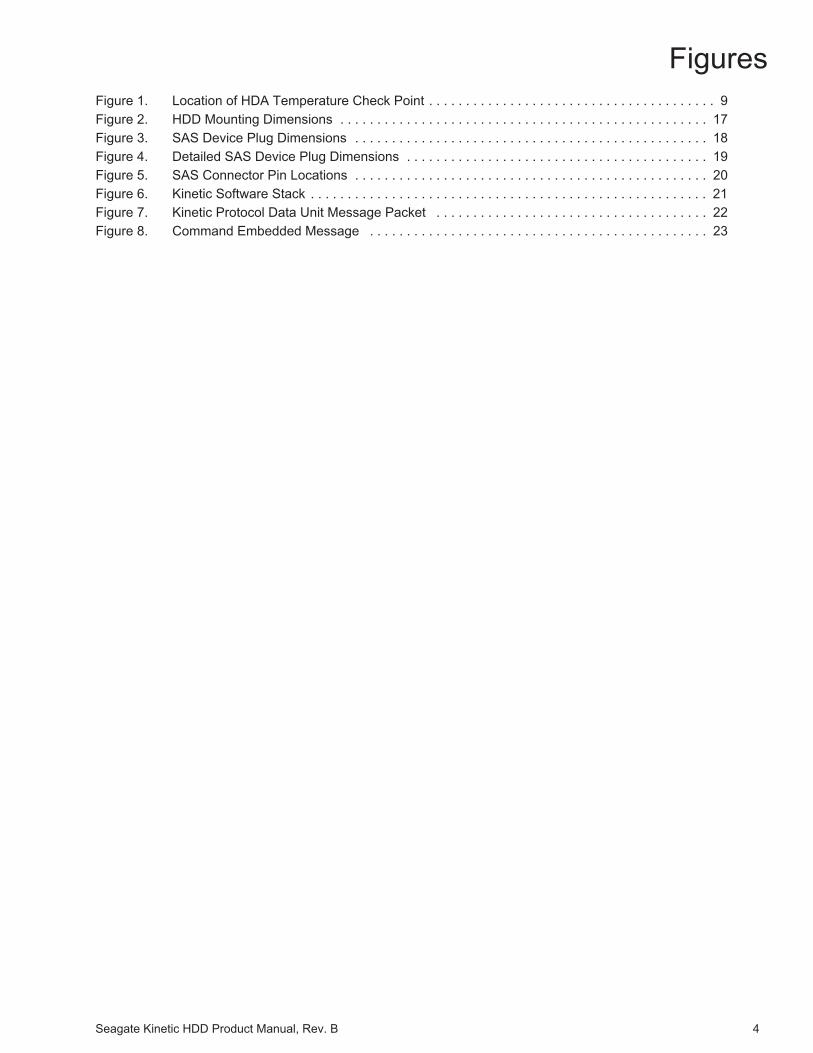
FiguresFigure 1. Location of HDA Temperature Check Point . . . . . . . . . . . . . . . . . . . . . . . . . . . . . . . . . . . . . . . 9Figure 2. HDD Mounting Dimensions . . . . . . . . . . . . . . . . . . . . . . . . . . . . . . . . . . . . . . . . . . . . . . . . . . 17Figure 3. SAS Device Plug Dimensions . . . . . . . . . . . . . . . . . . . . . . . . . . . . . . . . . . . . . . . . . . . . . . . . 18Figure 4. Detailed SAS Device Plug Dimensions . . . . . . . . . . . . . . . . . . . . . . . . . . . . . . . . . . . . . . . . . 19Figure 5. SAS Connector Pin Locations . . . . . . . . . . . . . . . . . . . . . . . . . . . . . . . . . . . . . . . . . . . . . . . . 20Figure 6. Kinetic Software Stack . . . . . . . . . . . . . . . . . . . . . . . . . . . . . . . . . . . . . . . . . . . . . . . . . . . . . . 21Figure 7. Kinetic Protocol Data Unit Message Packet . . . . . . . . . . . . . . . . . . . . . . . . . . . . . . . . . . . . . 22Figure 8. Command Embedded Message . . . . . . . . . . . . . . . . . . . . . . . . . . . . . . . . . . . . . . . . . . . . . . 23

Seagate Kinetic HDD Product Manual, Rev. B 5
For information regarding online support and services, visit: http://www.seagate.com/about/contact-us/technical-support/
Available services include:• Presales & Technical support• Global Support Services telephone numbers & business hours• Authorized Service Centers
For information regarding Warranty Support, visit: http://www.seagate.com/support/warranty-and-replacements/
For information regarding data recovery services, visit: http://www.seagate.com/services-software/data-recovery-services/
For Seagate OEM and Distribution partner portal, visit: http://www.seagate.com/partners/
For Seagate reseller portal, visit: http://www.seagate.com/partners/my-spp-dashboard/
Seagate® Technology Support Services

Seagate Kinetic HDD Product Manual, Rev. B 6
1.0 INTRODUCTION
This manual describes the functional, mechanical and interface specifications for the following: Seagate® Kinetic HDD model drives:
These drives provide the following key features:• 5900 RPM spindle speed.• High instantaneous (burst) data-transfer rates (up to 60MB per second).• Perpendicular recording technology provides the drives with increased areal density.• State-of-the-art cache and on-the-fly error-correction algorithms.• Simple GetLog command usage to obtain logged data information stored in device.• Supports Ethernet enabled SAS connectors (Connector pins shown in Table 4.1.1).• State-free Key-Value Object Store with Remote Procedure Calls (RPC).• Worldwide Name (WWN) capability uniquely identifies the drive.• Easy communication via Kinetic Application Programming Interface libraries.
1.1 ABOUT THE ETHERNET INTERFACE
The Ethernet provides advantages over traditional SATA and SAS interfaces. The primary advantages include:• Connects storage directly into existing data center fabric• Allows direct TCP/IP communication from any node in the network to the storage device• Eliminates traditional storage server needs as protocol communication• Retains the standard SAS hardware interface connector to provide system builder adaptability,
while enabling Ethernet
Model Number Seagate Instant Secure Erase (ISE)
ST4000NK001 Yes

Seagate Kinetic HDD Product Manual, Rev. B 7
2.0 DRIVE SPECIFICATIONS
Unless otherwise noted, all specifications are measured under ambient conditions, at 25°C, and nominal power. For convenience, the phrases the drive and this drive are used throughout this manual to indicate the following drive models:
2.1 FORMATTED CAPACITY
Table 1: HDD Capacity Information
*One GB equals one billion bytes and 1TB equals one trillion bytes when referring to hard drive capacity. Accessible capacity may vary depending on operating environment and formatting.
2.2 RECORDING AND INTERFACE TECHNOLOGY
Table 2: Recording and Interface Specifications
2.3 PHYSICAL CHARACTERISTICS
Table 3: Physical Characteristics
Seagate SED model
ST4000NK001
Model Formatted capacity* Guaranteed Objects Bytes per Object
ST4000NK001 4TB 3,906,250 Up to 1024KB
Interface 1-Gbps SGMII Ethernet
Recording method Perpendicular
Recording density, KBPI (Kb/in max) 1807
Track density, KTPI (ktracks/in avg) 340
Areal density (Gb/in2 avg) 625
Spindle speed (RPM) (± 0.2%) 5900
Internal data transfer rate (Mb/s max) 1813
Sustained data transfer rate (MiB/s) 20 to 60
I/O data-transfer rate (MB/s max) 60
Weight: (maximum)
Kinetic 4TB Model 608g (1.34 lb)
Cache buffer 64MB (67,108,864B)
RAM 512 MB (536,870,912B)
Software-on-Chip Marvell ARMADA 370

Seagate Kinetic HDD Product Manual, Rev. B 8
2.4 POWER SPECIFICATIONS• The drive receives DC power (+5V or +12V) through the Ethernet enabled SAS device connector.
• Three +12 volt pins provide power to the drive, 2 short and 1 long. The current return for the +12 volt power supply is through the common ground pins. The supply current and return current must be distributed as evenly as possi-ble among the pins.
• Three +5 volt pins provide power to the drive, 2 short and 1 long. The current return for the +5 volt power supply is through the common ground pins. The supply current and return current must be distributed as evenly as possible among the pins.
• Current to the drive through the long power pins may be limited by the system to reduce inrush current to the drive during hot plugging.
2.4.1 Power consumption• Power requirements for the drives are listed in Table 2.5.1. Typical power measurements are based on an average
of drives tested, under nominal conditions, using 5.0V and 12.0V input voltage at 25°C ambient temperature.• Spinup power:
Spinup power is measured from the time of power-on to the time that the drive spindle reaches operating speed.• Average Current Put / Get:
Drive operation consisted of continuous PUT / GET operations, 50/50 duty cycle.
Table 4: DC Power Requirements
2.4.2 Conducted Noise
Input noise ripple is measured at the host system power supply across an equivalent 80-ohm resistive load on the +12 voltline or an equivalent 15-ohm resistive load on the +5 volt line.
Using 12-volt power, the drive is expected to operate with a maximum of 120 mV peak-to-peak square-wave injected noiseat up to 10MHz.
Using 5-volt power, the drive is expected to operate with a maximum of 100 mV peak-to-peak square-wave injected noise atup to 10MHz.
2.4.3 Voltage Tolerance
Voltage Tolerance (including noise):• 5V ± 5%• 12V ± 10%
1.0Gb Mode
Voltage +5V +12V
Regulation ±5% ±10%
Maximum Spin-up Power
Peak DC (Watts) 3σ 5.0 19.2
Average Power (Put/Get)
Typical DC (Watts) 3σ 4.25 3.60
Note Equivalent resistance is calculated by dividing the nominal voltage by the typical RMS read/write current.

Seagate Kinetic HDD Product Manual, Rev. B 9
2.5 ENVIRONMENTAL LIMITS
Temperature and humidity values experienced by the drive must be such that condensation does not occur on anydrive part. Altitude and atmospheric pressure specifications are referenced to a standard day at 58.7°F (14.8°C).Maximum wet bulb temperature is 82°F (28°C).
2.5.1 Ambient Temperature
Operating
The drive meets the operating specifications over a 41°F to 140°F (5°C to 60°C) drive case temperature range with a maximum temperature gradient of 36°F (20°C) per hour.
The maximum allowable drive case temperature is 60°C. See Figure 2.5.1 for HDA case temperature measurement location
The MTBF specification for the drive assumes the operating environment is designed to maintain nominal case temperature. The rated MTBF is based upon a sustained case temperature of 104°F (40°C). Occasional excursions in operating temperature between the rated MTBF temperature and the maximum drive operating case temperature may occur without impact to the rated MTBF. However, continual or sustained operation at case temperatures beyond the rated MTBF temperature will degrade the drive MTBF and reduce product reliability.
Air flow may be required to achieve consistent nominal case temperature values. To confirm that the required cooling is provided for the electronics and HDA, place the drive in its final mechanical configuration, and perform random write/read operations. After the temperatures stabilize, measure the case temperature of the drive.
Non-operating
–40° to 158°F (–40° to 70°C) package ambient with a maximum gradient of 36°F (20°C) per hour. This specification assumes that the drive is packaged in the shipping container designed by Seagate for use with drive.
Figure 1 Location of HDA Temperature Check Point
NoteThe recommended storage period:
• 1 year under controlled conditions of 34°C 90%RH or less• 90 days in uncontrolled storage conditions
Note Image is for reference only, may not represent actual drive

Seagate Kinetic HDD Product Manual, Rev. B 10
2.5.2 HumidityTable 5: Humidity Specifications
2.5.3 AltitudeTable 6: Altitude Specifications
2.5.4 Shock
All shock specifications assume that the drive is mounted securely with the input shock applied at the drive mounting screws. Shock may be applied in the X, Y or Z axis.
2.5.4.1 Operating Shock
These drives comply with the performance levels specified in this document when subjected to a maximum operating shock of 70 Gs (read) and 40 Gs (write) based on half-sine shock pulses of 2 ms during read operations. Shocks should not be repeated more than two times per second.
2.5.4.2 Non-Operating Shock
The non-operating shock level that the drive can experience without incurring physical damage or degradation in performance when subsequently put into operation is 300 Gs based on a non-repetitive half-sine shock pulse of 2 ms duration.
2.5.5 Vibration
All vibration specifications assume that the drive is mounted securely with the input vibration applied at the drive mounting screws. Vibration may be applied in the X, Y or Z axis.
2.5.5.1 Operating Vibration
The maximum vibration levels that the drive may experience while meeting the performance standards specified in this document are specified below.
Table 7: Operating Vibration Specifications
* Rotary Random Operating Vibration
All vibration specifications assume that the drive is mounted securely with the input vibration applied at the drive mounting screws. Vibration may be applied in the X, Y or Z axis. Throughput may vary if improperly mounted.
2.5.5.2 Non-Operating Vibration
The maximum non-operating vibration levels that the drive may experience without incurring physical damage or degradation in performance when subsequently put into operation are specified below.
Table 8: Non-Operating Vibration Specifications
Operating 5% to 90% non-condensing (30% per hour max)
Non-Operating 5% to 95% non-condensing (30% per hour max)
Operating –304.80 m to 3048 m (–1000 ft. to 10,000+ ft.)
Non-Operating –304.80 m to 12,192 m (–1000 ft. to 40,000+ ft.)
5Hz to 22Hz 0.25 Gs
22Hz to 350Hz 0.50 Gs
350Hz to 500Hz 0.25 Gs
20Hz – 1500 Hz *(RROV) 12.5 rads/s2 with RVFF
10 Hz to 500 Hz Linear Random 4.9 Grms ref

Seagate Kinetic HDD Product Manual, Rev. B 11
2.6 ACOUSTICS
Drive acoustics are measured as overall A-weighted acoustic sound power levels (no pure tones). All measurements are consistent with ISO document 7779. Sound power measurements are taken under essentially free-field conditions over a reflecting plane. For all tests, the drive is oriented with the cover facing upward.
Table 9: Fluid Dynamic Bearing (FDB) Motor Acoustics
*During periods of drive idle, some offline activity may occur, which may increase acoustic and power to operational levels.
2.7 TEST FOR PROMINENT DISCRETE TONES (PDTS)Seagate follows the ECMA-74 standards for measurement and identification of PDTs. An exception to this process is the use of the absolute threshold of hearing. Seagate uses this threshold curve (originated in ISO 389-7) to discern toneaudibility and to compensate for the inaudible components of sound prior to computation of tone ratios according toAnnex D of the ECMA-74 standards.
2.8 ELECTROMAGNETIC IMMUNITYWhen properly installed in a representative host system, the drive operates without errors or degradation in performancewhen subjected to the radio frequency (RF) environments defined in Table 2.9.1
Table 10: Radio Frequency Environments
Test Description Performancelevel
Referencestandard
Electrostatic discharge Contact, HCP, VCP: ± 4 kV; Air: ± 8 kV B EN61000-4-2: 95
Radiated RF immunity80MHz to 1,000MHz, 3 V/m,80% AM with 1kHz sine900MHz, 3 V/m, 50% pulse modulation @ 200Hz
A EN61000-4-3: 96ENV50204: 95
Electrical fast transient ± 1 kV on AC mains, ± 0.5 kV on external I/O B EN61000-4-4: 95
Surge immunity ± 1 kV differential, ± 2 kV common, AC mains B EN61000-4-5: 95
Conducted RF immunity 150kHz to 80MHz, 3 Vrms, 80% AM with 1kHz sine A EN61000-4-6: 97
Voltage dips, interrupts
0% open, 5 seconds C
EN61000-4-11: 940% short, 5 seconds C40%, 0.10 seconds C70%, 0.01 seconds B
NoteFor seek mode tests, the drive is placed in seek mode only. The number of seeks per second is defined by the following equation:
Number of seeks per second = 0.4 / (average latency + average access time)
Idle* Put / Get Seek
4 Disks(4TB)
2.3 bels (typical)2.5 bels (max)
2.8 bels (typical)3.0 bels (max)

Seagate Kinetic HDD Product Manual, Rev. B 12
2.9 RELIABILITY
2.9.1 Annualized Failure Rate (AFR) and Mean Time Between Failures (MTBF)
The product shall achieve an Annualized Failure Rate (AFR) of 1.1% (MTBF of 800 thousand hours) when operateda nominal power and typical case temperatures of 40°C. Operation at temperatures outside the specifications in Section2.8 may increase the product AFR (decrease MTBF). AFR and MTBF are population statistics that are not relevant toindividual units.
AFR and MTBF specifications are based on the following assumptions for business critical storage system environments:• 8760 power-on-hours per year.• Operations at nominal voltages.• Temperatures outside the specifications in Section 2.8 may reduce the product reliability.• A workload rate below the average annualized specified limits. Operation at excessive I/O duty cycle may degrade
product reliability. • The enterprise application environment of power-on-hours, temperature, and I/O duty cycle effects the product
AFR and MTBF.
Table 11: AFR and MTBF Specifications
Nonrecoverable read errors 1 per 1014 bits read, max
Annualized Failure Rate 1.1% (nominal power, 40°C case temperature)
Load unload cycles 300,000 cycles
Rated Workload
Average rate of <180TB/yearThe MTBF specification for the drive assumes the I/O workload does not exceed the Average Annualized Workload Rate Limit of <180TB/year. Workloads exceeding the annualized rate may degrade the drive MTBF and impact product reliability. The Average Annualized Workload Rate Limit is in units of TB per year, or TB per 8760 power on hours. Workload Rate = TB transferred x (8760 / recorded power on hours).
Warranty
To determine the warranty for a specific drive, use a web browser to access the following web page: http://www.seagate.com/support/warranty-and-replacements/.From this page, click on the “Check to see if the drive is under Warranty” link. The following are required to be provided: the drive serial number, model number (or part number) and country of purchase.The system will display the warranty information for the drive.
Preventive maintenance None required.

Seagate Kinetic HDD Product Manual, Rev. B 13
2.10 AGENCY CERTIFICATION
2.10.1 Safety certification
These products are certified to meet the requirements of UL60950-1, CSA60950-1 and EN60950 and so marked as to the certify agency.
2.10.2 Electromagnetic compatibility
The Seagate Kinetic HDD hard drives are tested to a Class A standard per the CISPR 22 specification. Per the CISPR 22 specification “Class A ITE is a category of all other ITE which satisfies the class A ITE limits but not the class B ITE limits. Warning – This is a class A product. In a domestic environment this product may cause radio interference in which case the user may be required to take adequate measures.”
Drives are tested in representative end-user systems. Although CE-marked Seagate drives comply with the directiveswhen used in the test systems, we cannot guarantee that all systems will comply with the directives. The drive isdesigned for operation inside a properly designed enclosure, with properly shielded I/O cable (if necessary) andterminators on all unused IO ports. Computer manufacturers and system integrators should confirm EMC compliance and provide CE marking for their products.
Korean RRL
If these drives have the Korean Communications Commission (KCC) logo, they comply with paragraph 1 of Article 11 of the Electromagnetic Compatibility control Regulation and meet the Electromagnetic Compatibility (EMC) Framework requirements of the Radio Research Laboratory (RRL) Communications Commission, Republic of Korea.
These drives have been tested and comply with the Electromagnetic Interference/Electromagnetic Susceptibility (EMI/EMS) for Class A products. Drives are tested in a representative, end-user system by a Korean-recognized lab.
Australian Regulatory Compliance Mark (RCM)
If these models have the RCM marking, they comply with the Australia/New Zealand Standard AS/NZ CISPR22 and meet the Electromagnetic Compatibility (EMC) Framework requirements of the Australian Communications and Media Authority (ACMA).
2.10.3 FCC verification
These drives are intended to be contained solely within an enclosure (not attached as an external device). As such, eachdrive is considered to be a subassembly even when it is individually marketed to the customer. As a subassembly, noFederal Communications Commission verification or certification of the device is required.
Seagate has tested this device in enclosures as described above to ensure that the total assembly (enclosure, diskdrive motherboard, power supply, etc.) does comply with the limits for a Class A ITE device.
Radio and television interference. This equipment generates and uses radio frequency energy and if not installed andused in strict accordance with the manufacturer’s instructions, may cause interference to radio and television reception.
This equipment is designed to provide reasonable protection against such interference in a residential installation.
However there is no guarantee that interference will not occur in a particular installation. If this equipment does causeinterference to radio or television, which can be determined by turning the equipment on and off, users are encouraged totry one or more of the following corrective measures:
• Reorient the receiving antenna.• Move the device to one side or the other of the radio or TV.• Move the device farther away from the radio or TV.• Plug the computer into a different outlet so that the receiver and computer are on different branch outlets.
If necessary, users should consult the dealer or an experienced radio/television technician for additional suggestions.Users may find helpful the following booklet prepared by the Federal Communications Commission: How to Identify andResolve Radio-Television Interference Problems. This booklet is available from the Superintendent of Documents, U.S.Government Printing Office, Washington, DC 20402. Refer to publication number 004-000-00345-4.

Seagate Kinetic HDD Product Manual, Rev. B 14
2.11 ENVIRONMENTAL PROTECTION
Seagate designs its products to meet environmental protection requirements worldwide, including regulations restricting certain chemical substances.
2.11.1 European Union Restriction of Hazardous Substances (RoHS) Directive
The European Union Restriction of Hazardous Substances (RoHS) Directive, restricts the presence of chemical substances including Lead, Cadmium, Mercury, Hexavalent Chromium, PBB and PBDE, in electronic products, effective July 2006. This drive is manufactured with components and materials that comply with the RoHS Directive.
2.11.2 China Restriction of Hazardous Substances (RoHS) Directive
This product has an Environmental Protection Use Period (EPUP) of 20 years. The following table contains information mandated by China's "Marking Requirements for Control of Pollution Caused by Electronic Information Products" Standard.
"O" indicates the hazardous and toxic substance content of the part (at the homogeneous material level) is lower than the threshold defined by the China RoHS MCV Standard.
"X" indicates the hazardous and toxic substance content of the part (at the homogeneous material level) is over the threshold defined by the China RoHS MCV Standard.
2.12 CORROSIVE ENVIRONMENT
Seagate electronic drive components pass accelerated corrosion testing equivalent to 10 years exposure to lightindustrial environments containing sulfurous gases, chlorine and nitric oxide, classes G and H per ASTM B845.However, this accelerated testing cannot duplicate every potential application environment. Users should use cautionexposing any electronic components to uncontrolled chemical pollutants and corrosive chemicals, as the installation environment can affect electronic drive component reliability. The silver, copper, nickel and gold films used in Seagateproducts are especially sensitive to the presence of sulfide, chloride, and nitrate contaminants. Sulfur is found to be themost damaging. In addition electronic components should never be exposed to condensing water on the surface of theprinted circuit board assembly (PCBA) or exposed to an ambient relative humidity greater than 95%. Materials used incabinet fabrication, such as vulcanized rubber, that can outgas corrosive compounds should be minimized or eliminated.Replacing materials near circuitry with sulfide-free alternatives may extend the useful life of any electronic equipment.

Seagate Kinetic HDD Product Manual, Rev. B 15
2.13 PRODUCT WARRANTY
Beginning on the date of shipment to the customer and continuing for the period specified in the purchase contract, Seagate warrants that each product (including components and subassemblies) that fails to function properly undernormal use due to defect in materials or workmanship or due to nonconformance to the applicable specifications will berepaired or replaced, a Seagate’s option and at no charge to the customer, if returned by customer at customer’sexpense to Seagate’s designated facility in accordance with Seagate’s warranty procedure. Seagate will pay fortransporting the repair or replacement item to the customer. For more detailed warranty information, refer to thestandard terms and conditions of purchase for Seagate products on the purchase documentation.
The remaining warranty for a particular drive can be determined by calling Seagate Customer Service at 1-800-468-3472.Users can also determine remaining warranty using the Seagate web site (www.seagate.com). The drive serial number isrequired to determine remaining warranty information.
Shipping
When transporting or shipping a drive, use only a Seagate-approved container. Keep the original box. Seagateapproved containers are easily identified by the Seagate Approved Package label. Shipping a drive in a non-approvedcontainer voids the drive warranty.
Seagate repair centers may refuse receipt of components improperly packaged or obviously damaged in transit. Contactthe authorized Seagate distributor to purchase additional boxes. Seagate recommends shipping by an air-ride carrierexperienced in handling computer equipment.
Storage
The maximum recommended storage period for the drive in a non-operational environment is 90 days. Drives should bestored in the original unopened Seagate shipping packaging whenever possible. Once the drive is removed from theSeagate original packaging the recommended maximum period between drive operation cycles is 30 days. During anystorage period the drive non-operational temperature, humidity, wet bulb, atmospheric conditions, shock, vibration,magnetic and electrical field specifications should be followed.
Product Repair and Return Information
Seagate customer service centers are the only facilities authorized to service Seagate drives. Seagate does not sanction any third-party repair facilities. Any unauthorized repair or tampering with the factory seal voids the warranty.

Seagate Kinetic HDD Product Manual, Rev. B 16
3.0 CONFIGURING AND MOUNTING THE DRIVE
This section contains the specifications and instructions for configuring and mounting the drive.
3.1 HANDLING AND STATIC-DISCHARGE PRECAUTIONS
After unpacking, and before installation, the drive may be exposed to potential handling and electrostatic discharge (ESD) hazards. Observe the following standard handling and static-discharge precautions:
3.2 DRIVE MOUNTING
Users can mount the drive in any orientation using four screws in the side-mounting holes or four screws in the bottom- mounting holes. Refer to Figure 3.2.1 for drive mounting dimensions. Follow these important mounting precautions when mounting the drive:
• Allow a minimum clearance of 0.030 inches (0.76mm) around the entire perimeter of the drive for cooling.• Use only 6-32 UNC mounting screws.• The screws should be inserted no more than 0.150 inches (3.81mm) into the bottom or side mounting holes.• Do not over tighten the mounting screws (maximum torque: 6 inch-lb).
Caution
• Before handling the drive, put on a grounded wrist strap. Wear a grounded wrist strap throughoutthe entire installation procedure.
• Handle the drive by its edges or frame only.• The drive is extremely fragile—handle it with care. Do not press down on the drive top cover.• Always rest the drive on a padded, antistatic surface until users mount it in the computer.• Do not touch the connector pins or the printed circuit board.• Do not remove the factory-installed labels from the drive or cover them with additional labels. Removal
voids the warranty. Some factory-installed labels contain information needed to service the drive.Other labels are used to seal out dirt and contamination.
Weight: 608g (1.34 lb)
Note These dimensions conform to the Small Form Factor Standard documented in SFF-8301 and SFF-8323 found at www.sffcommittee.org

Seagate Kinetic HDD Product Manual, Rev. B 17
Figure 2 HDD Mounting Dimensions
3.3 DRIVE CONFIGURATIONS
When the Kinetic drives are connected to the local network with DHCP server, IP addresses will be self-assigned to each of the ports. Obtaining drive information, performing drive firmware updates, and other tools for drive configurations are provided in the Kinetic Python tools Github Repository: https://github.com/Seagate/kinetic-py-tools.
Note PCBA may not be representative of the actual PCBA on drive.

Seagate Kinetic HDD Product Manual, Rev. B 18
4.0 ETHERNET ENABLED INTERFACE
The Ethernet interface uses the standard SAS connector interface with repurposing of the pin outs. This section partially describes the interface requirements as implemented on Kinetic drives. The connector is defined by and conforms to the dimensions and specifications of SFF-8482 Rev 2.3.
4.1 SAS CONNECTOR PHYSICAL INTERFACEFigures 4.1.1 and 4.1.2 provide the dimensions of the SAS connector. Details of the physical, electrical, and logical characteristics are provided within this section.
Figure 3 SAS Device Plug Dimensions
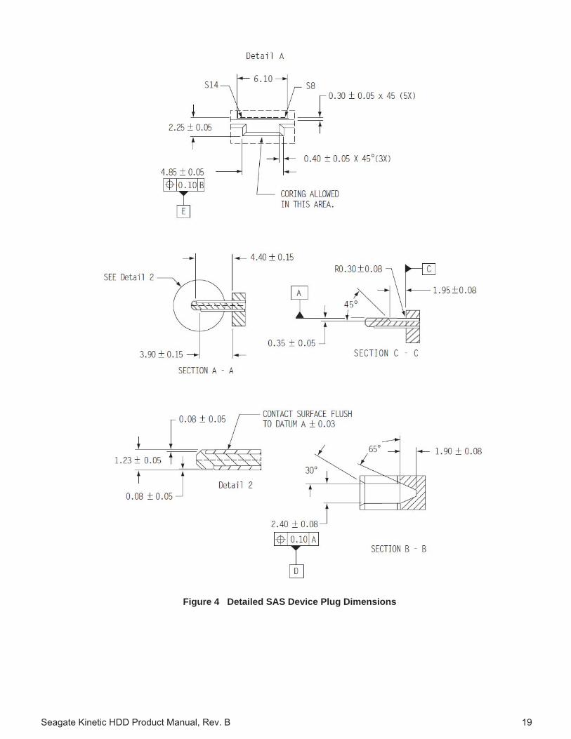
Seagate Kinetic HDD Product Manual, Rev. B 19
Figure 4 Detailed SAS Device Plug Dimensions

Seagate Kinetic HDD Product Manual, Rev. B 20
Figure 4.1.3 shows the pin locations for the SAS connector pin and Table 4.1.1 represents the Ethernet Enabled SAS Connector Pin Definitions for the Seagate Kinetic HDD.
Figure 5 SAS Connector Pin Locations
Table 12: Ethernet Enabled SAS Connector Pin Definitions
Notes• All pins are in a single row, with a 1.27 mm (0.050”) pitch.• There are three power pins for each voltage.
One pin from each voltage is used for pre-charge when installed in a blind-mate backplane configuration.• All used voltage pins must be terminated.
Segment Pin Function Comments
Signal
S1 GROUND S2 RX0+ Ethernet port 0S3 RX0- Ethernet port 0S4 GROUND S5 TX0- Ethernet port 0S6 TX0+ Ethernet port 0S7 GROUND S8 GROUND S9 RX1+ Ethernet port 1S10 RX1- Ethernet port 1S11 GROUND S12 TX1- Ethernet port 1S13 TX1+ Ethernet port 1S14 GROUND
Power
P1 RESERVED Reserved for internal use. Do not connect. 3.3V tolerant.P2 I2C CLOCK 3.3V tolerantP3 I2C DATA 3.3V tolerantP4 GROUND P5 GROUND P6 GROUND P7 +5V PRECHARGE P8 +5V P9 +5V P10 GROUND P11 RESERVED Reserved for internal use. Do not connect.P12 GROUND P13 +12V PRECHARGE P14 +12V P15 +12V

Seagate Kinetic HDD Product Manual, Rev. B 21
5.0 KEY/VALUE PROTOCOL
The protocol provides communication from the client applications to the Kinetic drive. The architecture for Kinetic storage is shown in Figure 5.1.
Figure 6 Kinetic Software Stack
This section explains the Kinetic Protocol Data Unit. For more information about the Kinetic Protocol, please visit: https://github.com/Seagate/kinetic-protocol.
5.1 HOST TO DRIVE DATA TRANSFER
Host to drive data transfer is accomplished using three basic commands:• put – Add the specified key/value object to the store• get – Retrieve the key/value object associated with the specified key• delete – Delete the key/value object that is associated with the specified key.
In addition to the basic commands, other key/value object operations are also supported:• getNext – Gets the key/value object associated with the key that follows the specified key based on the
lexicographical ordering of keys• getPrevious – Gets the key/value object associated with the key that precedes the specified key based on the
lexicographical ordering of keys• getKeyRange – Get a list of keys in lexicographical order based on the specified key range• getMetadata – Get metadata for the specified key
Host applications communicate with the Kinetic drives by sending Kinetic Protocol Data Units over a network using TCP.

Seagate Kinetic HDD Product Manual, Rev. B 22
5.2 KINETIC PROTOCOL DATA UNIT
A Kinetic PDU is composed of five fields1. PDU version2. Kinetic Message length3. value length4. Kinetic Message5. Value
Some PDUs have a null value. It is important to note that the value is not encoded in the Kinetic Message; it is a separate field of the Kinetic PDU.
Specifically, a Kinetic PDU structure is shown in Table 5.2.1.
Table 13: Kinetic PDU Structure
Figure 5.2.1 shows a visual of how the Kinetic PDU is structured.
Figure 7 Kinetic Protocol Data Unit Message Packet
Starting Offset Type Length Description
0 Byte 1 Byte PDU version: currently hex 46, denoting the beginning of the message.
1 4-byte Big Endian Integer 4 Bytes
The number of bytes in the Kinetic Message field. The maximum length for a Kinetic Message is 1 MiB (2^20 bytes).
5 4-byte Big Endian Integer 4 Bytes The number of bytes in the value field.
The maximum length for a value is 1 MiB (2^20 bytes).
9 Bytes <= 1 MiB The Kinetic Message.
9 + length of Kinetic Message Bytes <= 1 MiB The value.

Seagate Kinetic HDD Product Manual, Rev. B 23
5.3 KINETIC MESSAGE
The syntax and encoding of Kinetic Message is defined using Google Protocol Buffers and is specified by the file kinetic.proto. The top-level message, Message, contains three embedded messages:
1. Messagetype
2. hmacAuth
3. command
5.4 COMMAND EMBEDDED MESSAGE
Command is transported as bytes for ease of calculating the HMAC.
The command bytes are interpreted by casting them as embedded message, Command, containing three embedded messages:
1. Header – Contains metadata about type of message command, such as PUT, GET, and DELETE operations.
2. Body – Contains operation-specific information, such as key range information used for the GETKEYRANGE operations.
3. Status – Contains information about whether an associated operation succeeded or failed.
This is shown graphically in Figure 5.4.1.
Figure 8 Command Embedded Message
As shown in Figure 5.4.1, the Header, Body, and Status messages are all members of the Command message.

Seagate Technology LLCAMERICAS Seagate Technology LLC 10200 South De Anza Boulevard, Cupertino, California 95014, United States, 408-658-1000 ASIA/PACIFIC Seagate Singapore International Headquarters Pte. Ltd. 7000 Ang Mo Kio Avenue 5, Singapore 569877, 65-6485-3888EUROPE, MIDDLE EAST AND AFRICA Seagate Technology SAS 16-18 rue du Dôme, 92100 Boulogne-Billancourt, France, 33 1-4186 10 00
Publication Number: 100764174, Rev. B February 2015