Embed Size (px)
Citation preview

SEABROOK STATION ODCM
PART B
RADIOLOGICAL CALCULATIONAL METHODS AND PARAMETERS
ODCM Rev. 22B.1-0

TRP5.2-1.0 INTRODUCTION
The Offsite Dose Calculation Manual (ODCM) contains details to implement Technical
Requirements Program (TRP)5.2, "Radiological Effluent Controls and Environmental
Monitoring Program." TRP5.2 implements the requirements of Technical Specifications 6.7.6g
and 6.7.6h.
Part B of the ODCM provides formal and approved methods for the calculation of off-site
concentration, off-site doses and effluent monitor setpoints, and indicates the locations of
environmental monitoring stations in order to comply with the Seabrook Station Radiological
Effluent Controls Program (RECP), and Radiological Environmental Monitoring Program
(REMP) detailed in Part A of the manual. The ODCM forms the basis for station procedures
which document the off-site doses due to station operation which are used to show compliance
with the numerical guides for design objectives of Section II of Appendix I to 10CFR Part 50.
The methods contained herein follow accepted NRC guidance, unless otherwise noted in the text.
The references to 10 CFR Part 20 in Part B of the ODCM refer to revisions of 10 CFR Part 20
published prior to 1 January 1993. The decision to continue the use of the "old" version of 10
CFR Part 20 is based on an NRC letter dated June 30, 1993, from Thomas E. Murley to Thomas
E. Tipton. For the convenience of the plant staff a copy of 10 CFR Part 20 (Rev. 1 January 1992)
has been included in Appendix B.
TRP5.2-1.1 Responsibilities for Part B
All changes to the ODCM shall be reviewed and approved by the Station Operation Review
Committee (SORC), approved by the Station Director, and documented in accordance with
Technical Specification 6.13. The change process is controlled by the Regulatory Compliance
Manual (NARC) Chapter 6, §6.0, "Review, Approval and Issue of Technical Requirements."
Changes made to Part B shall be submitted to the Commission for their information in the
Annual Radioactive Effluent Release Report for the period in which the change(s) was made
effective.
It shall be the responsibility of the Station Director to ensure that the ODCM is used in the
performance of surveillance requirements and administrative controls in accordance with
Technical Specifications 6.7.6g and 6.7.6h, and Effluent Control Program and Radiological
Environmental Monitoring Program detailed in Part A of the manual.
ODCM Rev. 22B.1-1

In addition to off-site dose calculations for the demonstration of compliance with Technical Specification dose limits at and beyond the site boundary, 1 OCFR20.1302 requires that compliance with the dose limits for individual members of the public (100 mrem/yr total effective dose equivalent) be demonstrated in controlled areas on-site. Demonstration of compliance with the dose limits to members of the public in controlled areas is implemented per Health Physics Department Procedures, and is outside the scope of the ODCM. However, calculations performed in accordance with the ODCM can be used as one indicator of the need to perform an assessment of exposure to members of the public within the site boundary. Since external direct exposure pathways are already subject to routine exposure rate surveys and measurements, only the inhalation pathway need be assessed. The accumulated critical organ dose at the site boundary, as calculated per ODCM Part B Sections 3.9 and 3.11, can be used as an indicator of when additional assessments of on-site exposure to members of the public is advisable (see Section 3.11.2). Off-site critical organ doses from station effluents should not, however, be the only indicator of potential on-site doses.
ODCM Rev. 22B.1-2

TRP5.2-1.2 Summary of Methods, Dose Factors, Limits, Constants, Variables and Definitions
This section summarizes the Method I dose equations which are used as the primary means of demonstrating compliance with RECP. The concentration and setpoint methods are identified in Table B. 1-2 through Table B. 1-7. Appendix C provides documentation for an alternate computerized option, designated as Method LA in the ODCM, for calculating doses necessary to demonstrate compliance with RECP. The Effluent Management System (EMS) software package used for this purpose is provided by Canberra Industries, Inc. Where more refined dose calculations are needed, the use of Method II dose determinations are described in Sections 3.2 through 3.9 and 3.11. The dose factors used in the equations are in Tables B.I-10 through B.l-14 and the Regulatory Limits are summarized in Table B.I-1.
The variables and special definitions used in this ODCM, Part B, are in Tables B.1-8 and B.1-9.
ODCM Rev. 22B.1-3

TABLE B. 1-1 SUMMARY OF RADIOLOGICAL EFFLUENT PART A CONTROLS AND IMPLEMENTING EOUATIONS
Part A Control
Liquid Effluent Concentration
C.6.2.1 Liquid Effluent Dose
Category
Total Fraction of MPC Excluding Noble Gases
Total Noble Gas Concentration
Total Body Dose
Organ Dose
Liquid Radwaste Treatment Operability
Gaseous Effluents Dose Rate
Total Body Dose
Organ Dose
Total Body Dose Rate from Noble Gases
Skin Dose Rate from Noble Gases
Organ Dose Rate from 1- 131, 1-133, Tritium and Particulates with TI/2> 8 Days
Method I()
Eq. 2-1
Eq. 2-2
Eq. 3-1
Eq. 3-2
Eq. 3-1
Eq. 3-2
Eq. 3-3
Eq. 3-4
Eq. 3-5
Limit
< 1.0
< 2 x 10⁻⁴' Ci/ml
< 1.5 mrem in a qtr.
< 3.0 mrem in a yr.
< 5 mrem in a qtr.
< 10 mrem in a yr.
< 0.06 mrem in a mo.
< 0.2 mrem in a mo.
< 500 mrem/yr.
< 3000 mrem/yr.
< 1500 mrem/yr.
B.1-4
CODCM Rev. 22
C
C.6.1.1
C.6.3.1
C.7.1.1
C7

TABLE B.1-1 SUMMARY OF RADIOLOGICAL EFFLUENT PART A CONTROLS AND IMPLEMENTING EQUATIONS
(Continued)
Part A Control
Gaseous Effluents Dose from Noble Gases
Gaseous Effluents Dose from 1-131, 1-133, Tritium, and Particulates
Ventilation Exhaust Treatment
Total Dose (from All Sources)
Category
Gamma Air Dose from Noble Gases
Beta Air Dose from Noble Gases
Organ Dose from Iodines, Tritium and Particulates with TI/2 > 8 Days
Organ Dose
Method I(1)
Eq. 3-6
Eq. 3-7
Eq. 3-8
Eq. 3-8
Total Body Dose
Organ Dose
Thyroid Dose
Footnote (2).
Limit
< 5 mrad in a qtr.
< 10 mrad in a yr.
< 10 mrad in a qtr.
< 20 mrad in a yr.
< 7.5 mrem in a qtr.
< 15 mrem in a yr.
< 0.3 mrem in a mo.
< 25 mrem in a yr.
< 25 mrem in a yr.
< 75 mrem in a yr.
Liquid Effluent Monitor Setpoint
Liquid Waste Test Tank Monitor
Alarm Setpoint Eq. 5-1 Control C.6.1.1
ODCM Rev. 22
C.7.2.1
C.7.3.1
C.7.4.1
C.8.1.1
C.5.1
B. 1-5

TABLE B.1-1 SUMMARY OF RADIOLOGICAL EFFLUENT PART A CONTROLS AND IMPLEMENTING EQUATIONS
(Continued)
Part A Controls Category Method IM
Gaseous Effluent Monitor Setpoint
Plant Vent Wide Range Gas Monitors
Alarm/Trip Setpoint For Total Body Dose Rate
Alarm/Trip Setpoint for Skin Dose Rate
Eq. 5-9
Eq. 5-10
Control C.7.1.l a (Total Body)
Control C.7.1.l a (Skin)
(1) More accurate methods may be available (see subsequent chapters).
(2) Part A Control C.8.1.1a requires this evaluation only if twice the limit of equations 3-1, 3-2, 3-12, 3-15 or 3-18 is reached. If this occurs a Method II calculation, using actual release point parameters with annual average or concurrent meteorology and identified pathways for a real individual, shall be made.
ODCM Rev. 22
C.5.2
Limit
B.1-6

TABLE B. 1-2 SUMMARY OF METHOD I EQUATIONS TO CALCULATE
UNRESTRICTED AREA LIQUID CONCENTRATIONS
Equation Number Category
Total Fraction of WPC in Liquids, Except Noble Gases
Total Activity of Dissolved and Entrained Noble Gases from all Station Sources -NG CE-0
C~Gtjt) •2 E-04
ODCM Rev. 22
2-1
2-2
Equation
B.1-7

TABLE B.1-3 SUMMARY OF METHOD I EQUATIONS TO CALCULATE
OFF-SITE DOSES FROM LIQUID RELEASES
Equation Number Category Equation
Total Body Dose
Maximum Organ Dose
"D tb (mrem) = k Q DFL itb
"i Dmo(mrem)=kX•QiDFL.
mo imo
C
CODCM Rev. 22
3-1
3-2
B.1-8

/Th
Category
Total Body Dose Rate From Noble Gases
TABLE B. 1-4 SUMMARY OF METHOD I EQUATIONS TO CALCULATE DOSE RATES
Equation Receptor Release Number Locationa Heighte Equation
3-3a OS E Dib(e) = 0.85 * Doi * DFBi)
i
3-3b
3-3c
3-3d
3-3e
3-3f
OS
EC
EC
R
R
G
E
G
E
G
Dt•(g) = 3.4 * Doi * DFBi) i
btbE(e) = 0.0015 * * DFBi)
i DtbE(g) =0.0074 * E(1* DFBi)
DtbR(e) = 0.038 * =(Oi * DFBi)
15tbR(g) = 0.2 * Doi * DFBi)
aOs = Off-Site, EC = Science & Nature Center, formerly the Education Center, R = The "Rocks" bE = Elevated, G = Ground
ODCM Rev. 22B.1-9

TABLE B. 1-4 SUMMARY OF METHOD I EQUATIONS TO CALCULATE DOSE RATES
(Continued)
Equation Number
Receptor Locationa
Release Heightb Equation
Skin Dose Rate From Noble Gases
3-4a
3-4b
3-4c
3-4d
3-4e
3-4f
OS
OS
EC
EC
E
G
E
G
E
G
R
R
Dskin(e) = D oi * DF' i(e)) i
Dski,(g) =Z(( * DF'i(g)) i
DskinE(e) - 0.0014 * zQ * DF' 12(r)) i
Dski,,E(g) = 0.0014* ( * DF'iE(g)) i
DskinR(e) = 0.0076 * * DF' iR(e))
DskinR() = 0.0076 * oi* DF' iM(g)) i
aOs = Off-Site, EC = Science & Nature Center, formerly the Education Center, R = The "Rocks" bE = Elevated, G = Ground
B.1-10 ODCM Rev. 22
Category
C.
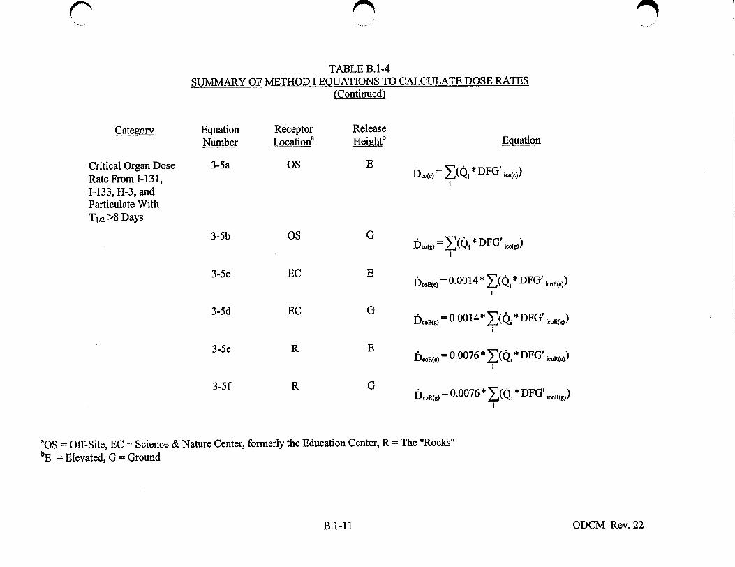
TABLE B.1-4 SUMMARY OF METHOD I EQUATIONS TO CALCULATE DOSE RATES
(Continued)
Equation Number
Receptor Locationa
Release Heightb Equation
Critical Organ Dose Rate From 1- 131, 1-133, H-3, and Particulate With TI/2 >8 Days
3-5a OS EDco(e) ( * DFG' ico(e))
OS
EC
EC
G
E
G
E
G
R
R
Dco(g) = ( * DFG' io,,()) i
IcoE() = 0.0014 * Z(0, * DFG' icoE(e)) !
Dcoog) = 0.0014.* (Q * DFG'icaE(g)) i
bcoR(e) = 0.0076 * * DFG' icoR(c))
i
Dcooft) = 0.0076 * E-"(o• * DFG' icoRfg))
i
'OS = Off-Site, EC = Science & Nature Center, formerly the Education Center, R = The "Rocks" bE = Elevated, G = Ground
ODCM Rev. 22
3-5b
3-5c
3-5d
3-5e
3-5f
B.1-11

TABLE B. 1-5 SUMMARY OF METHOD I EQUATIONS TO CALCULATE DOSES TO AIR FROM NOBLE GASES
Category
Gamma Dose to Air From Noble Gases
Equation Number
3-6a
3-6b
3-6c
3-6d
3-6e
3-6f
Receptor Locationa
OS
OS
EC
EC
R
R
Release Hgighb
E
G
E
G
E
G
Dair(e)
DWar(g)
DairE(e)
DairE(g)
DMrR(e)
DMaRfg)
= 3.21E-07
= 1.6E-06
= 4.9E-10
= 4.4 E-09
= 5.1 E-09
= 4.11E-08
Equation
* -0.275 * -(Q i i
* * (Q i
* t0 252 * (Qi i
* t0 321 * I *
i
St0.155 * (Q *
i
*t-0.204 2:-'(Q i*
i
aOS = Off-Site, EC = Science & Nature Center, formerly the Education Center, R = The "Rocks" bE = Elevated, G = Ground
B.1-12
n
ODCM Rev. 22
A
DF0)
DFY)
DFr)
DFr)
DFr)
DFID)

SUMMARY OF METHOD I EOUATIONS
Categor
Beta Dose to Air From Noble Gases
Equation Number
3-7a
3-7b
3-7c
3-7d
3-7e
3-7f
Receptor Locationa
OS
OS
EC
EC
R
R
SUMR ......................S
aoS = Off-Site, EC = Science & Nature Center, formerly the Education Center, R = The "Rocks" bE = Elevated, G = Ground
ODCM Rev. 22
rTABLE B. 1-5
TO CALCULATE DOSES TO AIR FROM NOBLE GASES (Continued)
Release H b Equation
E DWi) = 4.1E-07 * -"(Q* * DF,')
G Dig) = 6.0E-06 * * n * DFPI)
E D~rE~e) = 1.8E-09 * t' 35 *-(Qj * DFf')
G D jalp(g) = 2.E-08 * t-0.3 47 * Q * DF )
E Da•iR(g) = 3.9 E- 08 * t 0 249 (Q * DFe)
i G D api•Rf)/ = 4.6E-07 * t-0.211 * -'(Qj * DFf)
i
B.1-13

TABLE B. 1-6 SUMMARY OF METHOD I EQUATIONS TO CALCULATE
DOSE TO AN INDIVIDUAL FROM TRITIUM, IODINE AND PARTICULATES
Equation Number
Receptor Locationa
Release Heightb Equation
Dose to Critical Organ From Iodines, Tritium, and Particulates
3-8a OS E Dco(e) = 14.8 * t-0.297 * Y(Qi * DFGicoe))
G
E
G
E
G
Dco(g) = 17.7 * t"°316 * Y(Qj * DFGicog*))
Do E(e) = 3.3 E- 02 * t-0.349 * *.(Qi DFGo g(.)
DP. Ecg) = 3.3E- 02 * t"°0 347 * (Qi * DFGicoE(g))
DooR(e) = 7.3 E- 02 * t°'24 * (Q, DFGiwoR(c))
DcoR(g) = 8.6E- 02 * t-0 -267 * (Q* DFGicoR(g))
aOS = Off-Site, EC = Science & Nature Center, formerly the Education Center, R = The "Rocks" bE = Elevated, G = Ground
ODCM Rev. 22
Category
OS
EC
EC
3-8b
3-8c
3-8d
3-8e
3-8f
R
R
CB.1-14
'. j

TABLE B. 1-7 SUMMARY OF METHODS FOR SETPOINT DETERMINATIONS
Equation Number Category
Liquid Effluents: Liquid Waste Test Rsetpoint ml) FmX DFm Cyi
Tank Monitor (RM-6509)
PCCW Rate-of-Change Alarm
Gaseous Effluents:
Plant Vent Wide Range Gas Monitors (RM-6528-1, 2, 3)
Total Body
Skin
RC., (gph)= lxI 0-8 "SWF- 1 PCC
1 R (/Ci/sec) =588 1 f,
R(Ci/sec)= DFBc
R 13 O fl, .m.n (,uCi/sec) 30 k
ODCM Rev. 22
5-1
Equation
5-23
5-5
5-6
B.1-15

TABLE B. 1-8 SUMMARY OF VARUBLES
Variable
CNG
CING
Cdi
Ci
Cpi
Cy i
DPWIe)
DairR(e)
DIR(g.)
Dar(e)
Dyair(*g)
DyairE~e)
DrrE(g)
D~'iRIe)
Definition
Concentration at point of discharge and entrained noble gas 'T' in liquid pathways from all station sources
Total activity of all dissolved and entrained noble gases in liquid pathways from all station sources Concentration of radionuclide "i" at the point of liquid
discharge
- Concentration of radionuclide "iT
= Concentration, exclusive of noble gases, of radionuclide I"i from tank "p" at point of discharge
Concentration of radionuclide 'T' in mixture at the monitor
Off-site beta dose to air due to noble gases in elevated release
= Off-site beta dose to air due to noble gas in ground level release
- Beta dose to air at Science & Nature Center due to noble gases in elevated release
Beta dose to air at Science & Nature Center due to noble gases in ground level release
Beta dose to air at "Rocks" due to noble gases in elevated release
Beta dose to air at "Rocks" due to noble gases in ground level release
Off-site gamma dose to air due to noble gases in elevated release
Off-site gamma dose to air due to noble gases in ground level release
Gamma dose to air at Science & Nature Center due to noble gases in elevated release
Gamma dose to air at Science & Nature Center due to noble gases in ground level release
Gamma dose to air at "Rocks" due to noble gases in elevated release
ODCM Rev. 22
Units
gCi/rnl
gCi/nl
jItCi/ml
jtCi/ml
gCi/ml
tCi/ml
mrad
mrad
mrad
mrad
mrad
mrad
mrad
mrad
mrad
mrad
mrad
B.1-16

TABLE B. 1-8 SUMMARY OF VARIABLES
(Continued)
Variable
DairRIg)
Dco(e)
DcoE(e)
DcoE(g)
DcoR(e)
DcoR(g)
Dd
Dm,
Ds
Dtb
DF'n
DF'i
DF'?E
DF'im
DFBi
DFBC
DFLitb
Gamma dose to air at "Rocks" due to noble gases in ground level release
Critical organ dose from an elevated release to an off-site receptor
Critical organ dose from a ground level release to an off-site receptor
Critical organ dose from an elevated release to a receptor at the Science & Nature Center
Critical organ dose from a ground level release to a receptor at the Science & Nature Center
Critical organ dose from an elevated release to a receptor at the "Rocks"
Critical organ dose from a ground level release to a receptor at the "Rocks"
- Direct dose
- Gamma dose to air, corrected for finite cloud
- Dose to the maximum organ
- Dose to skin from beta and gamma
= Dose to the total body
- Minimum required dilution factor
- Composite skin dose factor for off-site receptor
- Composite skin dose factor for Science & Nature Center
- Composite skin dose factor for the "Rocks"
- Total body gamma dose factor for nuclide "i" (Table B.1-10)
Composite total body dose factor
Site-specific, total body dose factor for a liquid release of nuclide I"T (Table B. 1 -11)
Units
mrad
mrem
mrem
mrem
mrem
mrem
mrem
mrem
mrad
mrem
mrem
nmem
ratio
mrem-sec/RCi-yr
mrem-sec/gCi-yr
mrem-sec/pCi-yr 3
mrem pCi- yr
3 mrem pCi- yr
nirem/4Ci
ODCM Rev. 22B.1-17

Variable
DFI~mo
DFBico(e)
DFGico(g)
DFGicoE(e)
DFGicoE(g)
DFGi.o~e)
DFGicoR(g)
DFG'ica(e)
TABLE B. 1-8 SUMMARY OF VARIABLES
(Continued)
Definition
Site-specific, maximum organ dose factor for a liquid release of nuclide "i" (Table B. l-11)
Site-specific, critical organ dose factor for an elevated gaseous release of nuclide "i" (Table B.1-12)
Site-specific critical organ dose factor for a ground level release of nuclide "i" (Table B.l-12)
Science & Nature Center-specific critical organ dose factor for an elevated release of nuclide "i" (Table B.1-14)
Science & Nature Center-specific critical organ dose factor for a ground level release of nuclide "i" (Table B.1-14)
The "Rocks"-specific critical organ dose factor for an elevated release of nuclide "i" (Table B.1-15)
The "Rocks"-specific critical dose factor for a ground level release of nuclide "i" (Table B.1-15)
Site-specific critical organ dose rate factor for an elevated gaseous release of nuclide "i" (Table B. 1-12)
Site-specific critical organ dose rate factor for a ground level release of nuclide "i" (Table B.1-12)
Science & Nature Center-specific critical organ dose rate factor for an elevated release of nuclide "i" (Table B.1-14)
Science & Nature Center-specific critical organ dose rate factor for a ground level release of nuclide "i" (Table B. 1-14)
The "Rocks"-specific critical organ dose rate factor for an elevated release of nuclide "i" (Table B. 1-15)
The "Rocks"-specific critical organ dose rate factor for a ground level release of nuclide "i" (Table B.1-15)
Beta skin dose factor for nuclide "i" (Table B. 1-10)
Combined skin dose factor for nuclide "i" (Table B.I-10)
ODCM Rev. 22
Units
mrem/gCi
mrem/tCi
mrem/gCi
mrem/gCi
mrem/p.Ci
mrerrljiCi
mrem/gCi
mrem-sec/gCi-yr
mrem-sec/gCi-yr
mrem-sec/gCi-yr
mrem-seclgCi-yr
mrem-sec/gCi-yr
mrem-sec/[Ci-yr
mrem-m 3
pCi- yr
mrem- sec/gCi-yr
DFG'icoE(e)
DFG'?icOE(g)
DFG' icoR(e)
DFG' •.R(g)
DFSi
DF'i
C
C-B.1-18

TABLE B. 1-8 SUMMARY OF VARIABLES
(Continued)
Variable Definition Units
DFr Gamma air dose factor for nuclide "i' (Table B.I-10) mirad- m 3
pCi- yr
DFzi Beta air dose factor for nuclide "i" (Table B.1-10) mrad- m 3
pCi- yr
Dce = Critical organ dose rate to an off-site receptor due to nrem elevated release of iodines, tritium, and particulates yr
D5) = Critical organ dose rate to an off-site receptor due to mrem ground level release of iodines, tritium, and particulates yr
DcoE(e) Critical organ dose rate to a receptor at the Science & mrem Nature Center due to an elevated release of iodines, yr tritium, and particulates
D5 ) = Critical organ dose rate to a receptor at the Science & nmrem Nature Center due to a ground level release of iodines, yr tritium, and particulates
DCoRCC) = Critical organ dose rate to a receptor at the "Rocks" due nirem to an elevated release of iodines, tritium, and yr particulates
= Critical organ dose rate to a receptor at the "Rocks" due mrem to a ground level release of iodines, tritium, and yr particulates
DSlin~ Skin dose rate to an off-site receptor due to noble gases nrem in an elevated release yr
= Skin dose rate to an off-site receptor due to noble gases mnrem in a ground level release yr
IskiEe) Skin dose rate to a receptor at the Science & Nature nirem Center due to noble gases in an elevated release yr
= Skin dose rate to a receptor at the Science & Nature mrem Center due to noble gases in a ground level release yr
DskinR~e) Skin dose rate to a receptor at the "Rocks" due to noble rnrem gases in an elevated release yr
DsI5iR¢(g) Skin dose rate to a receptor at the "Rocks" due to noble mrem gases in a ground level release yr
ODCM Rev. 22B.1-19

Variable
Dtb(e)
Dth(g)
btbE(g)
Dtba(e)
DtbR(g)
D/Q
TABLE B.1-8 SUMMARY OF VARIABLES
(Continued)
Definition
Total body dose rate to an off-site receptor due to noble gases in an elevated release
Total body dose rate to an off-site receptor due to noble gases in a ground level release
Total body dose rate to a receptor at the Science & Nature Center due to noble gases in an elevated release
Total body dose rate to a receptor at the Science & Nature Center due to noble gases in a ground level release
Total body dose rate to a receptor at the "Rocks" due to noble gases in an elevated release
Total body dose rate to a receptor at the "Rocks" due to noble gases in a ground level release
Deposition factor for dry deposition of elemental radioiodines and other particulates
- The fraction of the offsite limiting total body dose rate
administratively assigned to the plant vent release
- Actual or estimated flow rate out of discharge tunnel
= Flow rate past liquid waste test tank monitor
- Maximum allowable discharge flow rate from liquid test tanks
The fraction of the offsite limiting total body dose rate administratively assigned to monitored ground level release
Flow rate past plant vent monitor cc
sec
Release reduction factor to be administratively assigned to account for potential unmonitored contributions from the Turbine Gland Seal Exhaust
Fraction of total MPC associated with Paths 1, 2, 3, and 4
Total fraction of MPC in liquid pathways (excluding noble gases)
B. 1-20
Dimensionless
Dimensionless
Dimensionless
ODCM Rev. 22
Units
mrem
yr
mrem
yr
mrem
yr
mrem
yr
mrem
yr
mrem
yr
1
m2
Dimensionless
gpm or ft3/sec
gpm
gpm
Dimensionless
Fd
Fm
F
fi; f2; f3; f4
FENG FI

TABLE B. 1-8 SUMMARY OF VARIABLES
(Continued)
Variable
MPCi
Qi
Qi Rsetpoint
Rskin
SF
Sg
Sgi
Si
Sli
X/Q
[X/Q]y
SWF
PCC
tfa
Definition
Maximum permissible concentration for radionuclide
"i" (10CFR20, Appendix B, Table 2, Column 2)
= Release to the environment for radionuclide "i"
Release rate to the environment for radionuclide "i"
= Liquid monitor response for the limiting concentration at the point of discharge
Response of the noble gas monitor to limiting total body
dose rate
Response of the noble gas monitor to limiting total body dose rate
= Shielding factor
Detector counting efficiency from the gas monitor
calibration
Detector counting efficiency for noble gas "i"
Detector counting efficiency from the liquid monitor
calibration
= Detector counting efficiency for radionuclide "i"
Average long-term undepleted atmospheric dispersion
factor (Tables B.7-4, B.7-5, and B.7-6)
Effective long-term average gamma atmospheric
dispersion factor (Tables B.7-4, B.7-5, and B.7-6)
= Service Water System flow rate
= Primary component cooling water measured (decay
corrected) gross radioactivity concentration
Unitless factor which adjusts the value of atmospheric
dispersion factors for elevated or ground-level releases
with a total release duration oft hours
Units
JICi/cc
curies, or Ii curies
IiCi/sec
JICi/ml
cpm, or gCi/sec
epm., or pCi/sec
Dimensionless
cpm mR/hr or
/pCi-cc /U Ci/cc
cpm omR/ hr
/g Ci- cc /p Ci/cc
cps/gCi/ml
cps/PCi/ml
sec
n?
sec
gph
gCi/ml
Dimensionless
ODCM Rev. 22B.1-21

TABLE B.1-9 DEFINITION OF TERMS
Critical Receptor - A hypothetical or real individual whose location and behavior cause him or her to receive a dose greater than any other possible real individual.
Dose - As used in Regulatory Guide 1.109, the term "dose," when applied to individuals, is used instead of the more precise term "dose equivalent," as defined by the International Commission on Radiological Units and Measurements (ICRU). When applied to the evaluation of internal deposition or radioactivity, the term "dose," as used here, includes the prospective dose component arising from retention in the body beyond the period of environmental exposure, i.e., the dose commitment. The dose commitment is evaluated over a period of 50 years. The dose is measured in mrem to tissue or mrad to air.
Dose Rate - The rate for a specific averaging time (i.e., exposure period) of dose accumulation.
Liquid Radwaste Treatment System - The components or subsystems which comprise the available treatment system as shown in Figure B.6-1.
ODCM Rev. 22B.1-22

C
Gamma Total Body Dose Factor
3 DFBi (.mrem- m3)
pCi- yr
8.84E-03 7.56E-08 1.17E-03 1.61E-05 5.92E-03 1.47E-02 1.66E-02 1.56E-02 9.15E-05 2.5 1E-04 2.94E-04 3.12E-03 1.81E-03 1.42E-03 8.83E-03
Beta Skin Dose Factor
3
DFSi j(rem- m) pCi- yr
2.69E-03
1.46E-03 1.34E-03 9.73E-03 2.37E-03 1.01E-02 7.29E-03 4.76E-04 9.94E-04 3.06E-04 7.11E-04 1.86E-03 1.22E-02 4.13E-03
Combined Skin Dose Factor for Elevated
Release Points I mrem- sec
DFi(e) ( - ) p Ci- yr
1.09E-02 1.81E-05 2.35E-03 1.11E-03 1.38E-02 1.62E-02 2.45E-02 2.13E-02 5.37E-04 1.12E-03 5.83E-04 3.74E-03 3.33E-03 1. 14E-02 1.20E-02
Combined Skin Dose Factor for Ground
Level Release Points DF'it (mrem- sec)
D i(g)( , Ci- yr
6.20E-02 7.28E-05 1.92E-02 1.35E-02 1.21E-01 8. 1OE-02 1.66E-01 1.34E-01 5.35E-03 1.12E-02 4.39E-03 1.98E-02 2.58E-02 1.28E-01 7.60E-02
Beta Air Dose Factor
DFj ( Iirad - m3 pCi - yr
3.28E-03 2.88E-04 1.97E-03 1.95E-03 1.03E-02 2.93E-03 1.06E-02 7.83E-03 1.11 E-03 1.48E-03 1.05E-03 7.39E-04 2.46E-03 1.27E-02 4.75E-03
Gamma Air Dose Factor
D r mrad-m 3 "iDF " pCi- yr
9.30E-03 1.93E-05 1.23E-03 1.72E-05 6.17E-03 1.52E-02 1.73E-02 1.63E-02 1.56E-04 3.27E-04 3.53E-04 3.36E-03 1.92E-03 1.51E-03 9.21E-03
8.84E-03 = 8.84 x 10⁻³
ODCM Rev. 22
C
TABLE B.1-10 DOSE FACTORS SPECIFIC FOR SEABROOK STATION FOR NOBLE GAS RELEASES
Radionuclide
Ar-41 Kr-83m Kr-85m Kr-85 Kr-87 Kr-88 Kr-89 Kr-90 Xe-131m Xe-133m Xe-133 Xe-135m Xe-135 Xe-137 Xe-138
B. 1-23

DOSE FACTORSTABLE B.1-11
SPECIFIC FOR SEABROOK STATION FOR
LIQUID RELEASES
Total Body Dose Factor
Dose factors to be used in Method I calculation for any "other" detected gamma emitting radionuclide which is not included in the above list.
ODCM Rev. 22B.1-24
Radionuclide
H-3 Na-24 Cr-51 Mn-54 Fe-55 Fe-59 Co-58 Co-60 Zn-65 Br-83 Rb-86 Sr-89 Sr-90 Nb-95 Mo-99
Tc-99m Ag-1 10in Sb-124 Sb-125
Te-127m Te-127
Te-129m Te-129
Te-131m Te-132
1-130 1-131 1-132 1-133 1-134 1-135
Cs-134 Cs-136 Cs-137 Ba-140 La-140 Ce-141 Ce-144 Other*
(mlem) DFLit ( / .i
3.02E-13 1.38E-10 1.83E-1I 5.15E-09 1.26E-08 8.74E-08 2.46E-09 6.15E-08 2.73E-07 1.30E-14 4.18E-10 2.17E-10 3.22E-08 5.25E-10 3.72E- 1I 5.22E-13 1.OIE-08 1.71E-09 6.28E-09 7.07E-08 3.53E-10 1.54E-07 7.02E-14 3.16E-08 9.06E-08 2.75E-1 1 2.30E-10 6.28E-11 3.85E-1 1 1.19E-12 5.33E-1 1 3.24E-08 2.47E-09 3.58E-08 1.70E-10 1.07E-10 3.85E-1 1 1.96E-10
3.12E-08*
Maximum Organ Dose Factor
(trero D FLimo ( "
,uCi 3.02E-13 1.42E-10 1.48E-09 2.68E-08 7.67E-08 6.66E-07 1.40E-08 9.22E-08 5.49E-07 1.89E-14 6.96E-10 7.59E-09 1.31E-07 1.58E-06 2.67E-10 1.95E-12 6.40E-07 9.89E-09 8.3 1E-09 1.81E-06 9.54E-08 3.46E-06 1.05E-13 2.94E-06 3.80E-06 3.17E-09 1.OOE-07 6.36E-1 1 1.15E-08 1.41E-12 4.69E-10 3.56E-08 3.27E-09 4.03E-08 3.49E-09 4.14E-08 9.31E-09 6.46E-08 1.58E-06*

TABLE B.1-12 DOSE AND DOSE RATE FACTORS SPECIFIC FOR SEABROOK STATION
FOR IODINES, TRITIUM AND PARTICULATE RELEASES
Critical Organ Dose Factor for Elevated
Release Point (mrem
DFGico() CiRadionuclide
H-3
Cr-51
Mn-54
Fe-59
Co-58
Co-60
Zn-65
Sr-89
Sr-90
Zr-95
Nb-95
Mo-99
Ru-103
Ag-1 10m
Sb-124
1-131
1-133
Cs-134
Cs-137
Ba-140
Ce-141
Ce-144
Other*
Critical Organ Dose Factor for Ground
Level Release Point
DFGim(g) ( Ci
3.76E-09
2.89E-08
3.79E-06
3.65E-06
1.91E-06
4.12E-05
7.93E-06
6.73E-05
2.47E-03
3.77E-06
6.86E-06
1.10E-07
1.04E-05
1.72E-05
6.28E-06
5.04E-04
5.72E-06
1.91E-04
1.86E-04
6.39E-07
9.28E-07
2.09E-05
1.39E-05
Critical Organ Dose Rate Factor for Elevated
Release Point
tomrem-sec DFG') yr-pCi
9.71E-03
2.91E-01
4.38E+01
3.53E+01
2.00E+01
5.42E+02
7.82E+01
6.24E+02
2.27E+04
3.63E+01
6.40E+01
5.39E-01
9.62E+01
1.80E+02
6.15E+01
4.64E+03
4.57E+01
1.81E+03
1.79E+03
5.01E+00
8.45E+00
1.93E+02
1.29E+02
Critical Organ Dose Rate Factor for Ground
Level Release Point
DFG'ic, (.emrem- sec
yr-f pCi
1.19E-01
1.01E+00
1.50E+02
1.21E+02
6.88E+01
1.85E+03
2.66E+02
2.12E+03
7.79E+04
1.24E+02
2.20E+02
3.56E+00
3.3 1E+02
6.15E+02
2.11 E+02
1.59E+04
1.80E+02
6.18E+03
6.09E+03
2.06E+01
2.96E+01
6.62E+02
4.38E+02
* Dose factors to be used in Method I calculations for any "other" detected gamma emitting radionuclide which is not included in the above list.
ODCM Rev. 22
3.08E-10
8.28E-09
1.11E-06
1.06E-06
5.56E-07
1.21E-05
2.33E-06
1.98E-05
7.21E-04
1.1OE-06
2.01E-06
1.63E-08
3.03E-06
5.02E-06
1.83E-06
1.47E-04
1.45E-06
5.62E-05
5.47E-05
1.55E-07
2.65E-07
6.09E-06
4.09E-06
B.1-25

TABLE B.I-13 COMBINED SKIN DOSE RATE FACTORS SPECIFIC FOR SEABROOK STATION
SPECIAL RECEPTORS(') FOR NOBLE GAS RELEASE
Science & Nature Center
Combined Skin Dose Rate Factor for
Elevated Release Point
DF? (mrem-sec) p Ci- yr
1.57E-02
2.35E-05
3.84E-03
2.16E-03
2.31E-02
2.23E-02
3.73E-02
3.15E-02
9.52E-04
1.99E-03
9.20E-04
5.24E-03
5.32E-03
2.14E-02
1.78E-02
Science & Nature Center
Combined Skin Dose Rate Factor for
Ground Level Release Point
DF' (mrem- sec) DM(g) P Ci- yr
1.17E-01
1.13E-04
4.08E-02
3.09E-02
2.60E-01
1.44E-01
3.34E-01
2.64E-01
1.19E-02
2.48E-02
9.1 IE-03
3.61E-02
5.41E-02
2.89E-01
1.49E-01
The "Rocks" Combined Skin
Dose Rate Factor for Elevated Release Point
DF' Me)mrem-sec) DF'R( / ( Ci- yr
9.73E-02
1.07E-04
3.16E-02
2.29E-02
2.OOE-01
1.25E-01
2.68E-01
2.14E-01
8.96E-03
1.87E-02
7.16E-03
3.07E-02
4.23E-02
2.16E-01
1.21E-01
The "Rocks" Combined Skin
Dose Rate Factor for Ground Level Release
Point
DForero-sec) F'R(g) ( ,Ci-
6.99E-01
5.57E-04
2.69E-01
2.15E-01
1.73E+00
8.18E-01
2.12E+00
1.64E+00
8.07E-02
1.68E-01
5.91E-02
2.11E-01
3.53E-01
2.OOE+00
9.27E-01
"(1) See Seabrook Station Technical Specification Figure 5.1-1.
ODCM Rev. 22
N
Radionuclide
Ar-41
Kr-83m
Kr-85m
Kr-85
Kr-87
Kr-88
Kr-89
Kr-90
Xe-131m
Xe-133m
Xe-133
Xe-135m
Xe-135
Xe-137
Xe-138
B. 1-26
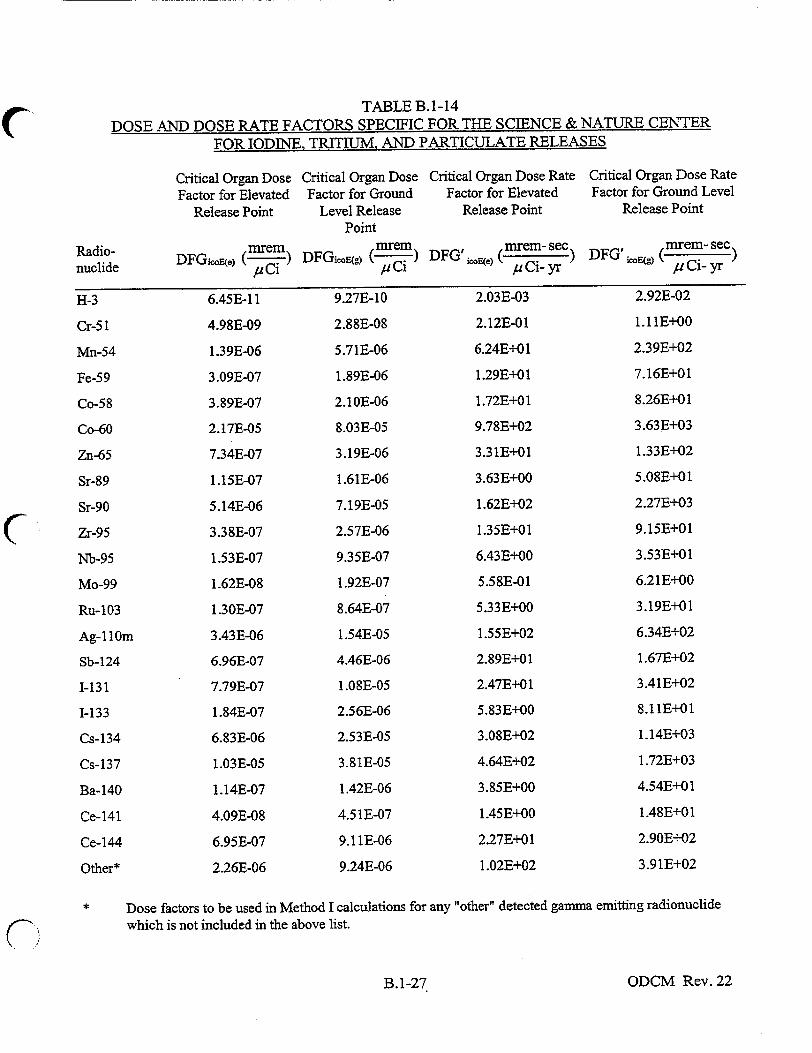
TABLE B.1-14
DOSE AND DOSE RATE FACTORS SPECIFIC FOR THE SCIENCE & NATURE CENTER
FOR IODINE, TRITIUM, AND PARTICULATE RELEASES
Radionuclide
H-3
Cr-51
Mn-54
Fe-59
Co-58
Co-60
Zn-65
Sr-89
Sr-90
Zr-95
Nb-95
Mo-99
Ru-103
Ag-ll0m
Sb-124
1-131
1-133
Cs-134
Cs-137
Ba-140
Ce-141
Ce-144
Other*
Critical Organ Dose Factor for Elevated
Release Point
mrem DFGiMCe) ( )Ci
6.45E-1 1
4.98E-09
1.39E-06
3.09E-07
3.89E-07
2.17E-05
7.34E-07
1.15E-07
5.14E-06
3.38E-07
1.53E-07
1.62E-08
1.30E-07
3.43E-06
6.96E-07
7.79E-07
1.84E-07
6.83E-06
1.03E-05
1.14E-07
4.09E-08
6.95E-07
2.26E-06
Critical Organ Dose Factor for Ground
Level Release Point
mrem DFGi.oE(g) ( Ci
9.27E-10
2.88E-08
5.71E-06
1.89E-06
2.10E-06
8.03E-05
3.19E-06
1.61E-06
7.19E-05
2.57E-06
9.35E-07
1.92E-07
8.64E-07
1.54E-05
4.46E-06
1.OSE-05
2.56E-06
2.53E-05
3.81E-05
1.42E-06
4.5 1E-07
9.1 1E-06
9.24E-06
Critical Organ Dose Rate Factor for Elevated
Release Point
DFG' icoE(e) (mrem- sec) p Ci- yr
2.03E-03
2.12E-01
6.24E+01
1.29E+01
1.72E+01
9.78E+02
3.31E+01
3.63E+00
1.62E+02
1.35E+01
6.43E+00
5.58E-01
5.33E+00
1.55E+02
2.89E+01
2.47E+01
5.83E+00
3.08E+02
4.64E+02
3.85E+00
1.45EE+00
2.27E+01
1.02E+02
Dose factors to be used in Method I calculations for any "other" detected gamma emitting radionuclide which is not included in the above list.
ODCM Rev. 22
Critical Organ Dose Rate Factor for Ground Level
Release Point
DFG' icE) (tomrem- sec
/lCi- yr
2.92E-02
1.11 E+00
2.39E+02
7.16E+01
8.26E+01
3.63E+03
1.33E+02
5.08E+01
2.27E+03
9.15E+01
3.53E+01
6.21E+00
3.19E+01
6.34E+02
1.67E+02
3.41E+02
8.11E+O 1
1.14E+03
1.72E+03
4.54E+01
1.48E+01
2.90E+02
3.91E+02
B. 1-27

TABLE B.1-15 DOSE AND DOSE RATE FACTORS SPECIFIC FOR THE "ROCKS"
FOR IODINE, TRITIUM, AND PARTICULATE RELEASES
Critical Organ Dose Factor
for Elevated Release Point
(mrem DFGicoI~ep /.CiRadio
nuclide
H-3
Cr-5I
Mn-54
Fe-59
Co-58
Co-60
Zn-65
Sr-89
Sr-90
Zr-95
Nb-95
Mo-99
Ru-103
Ag-110m
Sb-124
1-131
1-133
Cs-134
Cs-137
Ba-140
Ce-141
Ce-144
Other*
Critical Organ Dose Factor for Ground
Level Release Point
(mrem) DFGicoR(g- (pC
6.45E-09
1.75E-07
3.18E-05
1.17E-05
1.25E-05
4.09E-04
1.80E-05
1.15E-05
5.14E-04
1.68E-05
5.79E-06
1.34E-06
5.47E-06
8.77E-05
2.80E-05
7.73E-05
1.83E-05
1.29E-04
1.94E-04
9.99E-06
3.14E-06
6.46E-05
5.09E-05
Critical Organ Dose Rate Factor for Elevated
Release Point
(tmrem- sec) DFG 'icoI~e• /,u Ci- yr
2.16E-02
1.07E+00
2.55E+02
6.78E+01
8.11E+01
3.97E+03
1.37E+02
3.88E+01
1.73E+03
8.14E+01
3.37E+01
4.92E+00
2.95E+01
6.47E+02
1.56E+02
2.61E+02
6.18E+01
1.25E+03
1.89E+03
3.56E+01
1.20E+01
2.25E+02
4.16E+02
Critical Organ Dose Rate Factor for Ground Level
Release Point
DFG' icOR() (mrem se) ~uiyr
2.03E-01
6.53E+00
1.31E+03
4.29E+02
4.79E+02
1.85E+04
7.29E+02
3.63E+02
1.62E+04
5.83E+02
2.13E+02
4.32E+01
1.96E+02
3.53E+03
1.01E+03
2.44E+03
5.77E+02
5.80E+03
8.77E+03
3.19E+02
1.02E+02
2.05E+03
2.12E+03
Dose factors to be used in Method I calculations for any "other" detected gamma emitting radionuclide which is not included in the above list.
ODCM Rev. 22
2
6.85E-10
2.68E-08
5.84E-06
1.74E-06
2.01E-06
8.83E-05
3.23E-06
1.23E-06
5.48E-05
2.22E-06
8.59E-07
1.50E-07
7.74E-07
1.54E-05
4.04E-06
8.27E-06
1.95E-06
2.78E-05
4.19E-05
1.1OE-06
3.59E-07
7.02E-06
9.56E-06
B.1-28

(W, -.- I
ERG F =YE E1. P MPC,
Ci/ mi)
and:
(2-1)
(2-2)C'G = C 2E-04 1i ]
(GCi/ml)
Total fraction of MPC in liquids, excluding noble gases, at the point of discharge from the
multiport difuser.
ODCM Rev. 21
where:
F1G
GLCi/ml) (gci/ml)
B.2-1
TPR5.2-2.0 METHOD TO CALCULATE OFF-SITE LIQUID CONCENTRATIONS
Chapter 2 contains the basis for station procedures used to demonstrate compliance with ODCM Part A Control C.6. 1.1, which limits the total fraction of MPC in liquid pathways, other than noble gases
(denoted here as F G ) at the point of discharge from the station to the environment (see Figure B.6-1).
F NG is limited to less than or equal to one, i.e.,
F, EG _<I
The total concentration of all dissolved and entrained noble gases at the point of discharge from
the multiport diffuser from all station sources combined, denoted C'G , is limited to
2E-04 gaCi/ml, i.e.,
CING < 2E-04 gtCi/ml.
Appendix C, Attachments 3 and 4, provide the option and bases for the use of the EMS determination of liquid concentration limits for plant discharges to the environment.
TRP5.2-2.1 Method to Determine F1 AND C1 NG
First, determine the total fraction of MPC (excluding noble gases), at the point of discharge from
the station from all significant liquid sources denoted F G; and then separately determine the
total concentration at the point of discharge of all dissolved and entrained noble gases from all
station sources, denoted C G, as follows:

Cpi Concentration at point of discharge from the multiport diffuser of radionuclide "T', except for dissolved and entrained noble gases, from all tanks and other significant sources, p, from which a discharge may be made (including the waste test tanks and any other significant source from which a discharge can be made). Cpi is determined by dividing the product of the measured radionuclide concentration in liquid waste test tanks, PCCW, steam generator blowdown, or other effluent streams times their discharge flow rate by the total available dilution water flow rate of circulating and service water at the time of release (gCi/ml).
MPCi Maximum permissible concentration of radionuclide 'iT except for dissolved and entrained noble gases from 10CFR20, Appendix B, Table II, Column 2 (PCi/ml). See Appendix B for a list of MPC values.
C1 NG = Total concentration at point of discharge of all dissolved and entrained noble gases in liquids from all station sources (gtCi/ml)
C iNG = Concentration at point of discharge of dissolved and entrained noble gas "i" in liquids from all station sources (gtCi/ml)
TRP5.2-2.2 Method to Determine Radionuclide Concentration for Each Liquid Effluent Source
2.2.1 Waste Test Tanks
Cpi is determined for each radionuclide detected from the activity in a representative grab sample of any of the waste test tanks and the predicted flow at the point of discharge.
The batch releases are normally made from two 25,000-gallon capacity waste test tanks. These tanks normally hold liquid waste which may have been processed through the installed vendor equipment. The waste test tanks can also contain other waste such as liquid taken directly from the floor drain/chemical drain treatment tanks when that liquid does not require processing in the evaporator, from the installed vendor resin skid, distillate from the boron recovery evaporator when the BRS evaporator is substituting for the waste evaporator, or waste distillate from the Steam Generator Blowdown System when that system must discharge liquid off site.
If testing indicates that purification of the waste test tank contents is required prior to release, the liquid can be circulated through the waste demineralizer and filter.
The contents of the waste test tank may be reused in the Nuclear System if the sample test meets the purity requirements.
Prior to discharge, each waste test tank is analyzed for principal gamma emitters in accordance with the liquid sample and analysis program outlined in Part A to the ODCM.
ODCM Rev. 21B.2-2

2.2.2 Turbine Building Sump
The Turbine Building sump collects leakage from the Turbine Building floor drains and
discharges the liquid unprocessed to the circulating water system.
Sampling of this potential source is normally done once per week for determining the
radioactivity released to the environment (see Table A.6. 1-1).
2.2.3 Steam Generator Blowdown Flash Tank
The primary method to process radioactive secondary liquid from the steam generators is
to direct steam blowdown flash tank bottoms cooler discharge to the floor drain tanks. If
no secondary pressure is available, the steam blowdown and wet lay-ups pumps can be
used. From the floor drain tanks, processing through the installed vendor resin skid
(WL-SKD-135) to the waste test tanks is the preferred method. Other methods may be
used as defined below.
The steam generator blowdown evaporators may process the liquid from the steam
generator blowdown flash tank when there is primary to secondary leakage. Distillate
from the evaporators can be sent to the waste test tanks or recycled to the condensate
system. When there is no primary to secondary leakage, flash tank liquid is processed
through the steam generator blowdown demineralizers and returned to the secondary side.
Steam generator blowdown is only subject to sampling and analysis when all or part of
the blowdown liquid is being discharged to the environment instead of the normal recycling process (see Table A.6.1-1).
2.2.4 Primary Component Cooling Water (PCCW) System
The PCCW System is used to cool selected primary components.
The system is normally sampled weekly to determine if there is any radwaste in-leakage.
If leakage has been determined, the Service Water System is sampled to determine if any release to the environment has occurred.
ODCM Rev. 21B.2-3

TRP5.2-3.0 OFF-SITE DOSE CALCULATION METHODS
Chapter 3 provides the basis for station procedures required to meet the Radiological Effluent Control Program (RECP) dose and dose rate requirements contained in ODCM Part A Controls. A simple, conservative method (called Method I) is listed in Tables B. 1-2 to B. 1-7 for each of the requirements of the RECP. Each of the Method I equations is presented in Part B, Sections 3.2 through 3.9. As an alternate to Method I, the EMS computer program documented in Appendix C can be used to determine regulatory compliance for effluent doses and dose rates. The use of
the EMS software is designated as Method IA in Chapter 3. In addition, those sections include more sophisticated methods (called Method II) for use when more refined results are needed. This chapter provides the methods, data, and reference material with which the operator can calculate the needed doses, dose rates and setpoints. For the requirements to demonstrate compliance with Part A off-site dose limits, the contribution from all measured ground level releases must be added to the calculated contribution from the vent stack to determine the Station's total radiological impact. The bases for the dose and dose rate equations are given in Chapter 7.0. Method IA bases and software verification documentation are contained in Appendix C.
The Annual Radioactive Effluent Release Report, to be filed after January 1 each year per Technical Specification 6.8.1.4, and Part A, Section 10.2, requires that meteorological conditions concurrent with the time of release of radioactive materials in gaseous effluents, as determined by sampling frequency and measurement, be used for determining the gaseous pathway doses. For continuous release sources (i.e., plant vent, condenser air removal exhaust, and gland steam packing exhauster), concurrent quarterly average meteorology will be used in the dose calculations along with the quarterly total radioactivity released. For batch releases or identifiable operational activities (i.e., containment purge or venting to atmosphere of the Waste Gas System), concurrent meteorology during the period of release will be used to determine dose if the total noble gas or iodine and particulates released in the batch exceeds five percent of the total quarterly radioactivity released from the unit; otherwise quarterly average meteorology will be applied. Quarterly average meteorology will also be applied to batch releases if the hourly met data for the period of batch release is unavailable.
Annual dose assessment reports prepared in accordance with the requirements of the ODCM will include a statement indicating that the appropriate portions of Regulatory Guide 1.109 (as identified in the individual subsections of the ODCM for each class of effluent exposure) have been used to determine dose impact from station releases. Any deviation from the methodology, assumptions, or parameters given in Regulatory Guide 1.109, and not already identified in the bases of the ODCM, will be explicitly described in the effluent report, along with the bases for the deviation.
ODCM Rev. 22B.3-1

TRP5.2-3.1 Introductory Concepts
In Part A Controls, the RECP limits for dose or dose rate are stated. The term "dose" for ingested or inhaled radioactivity means the dose commitment, measured in mrem, which results from the exposure to radioactive materials that, because of uptake and deposition in the body, will continue to expose the body to radiation for some period of time after the source of radioactivity is stopped. The time frame over which the dose commitment is evaluated is 50 years. The phrases "annual dose" or "dose in one year" then refers to the 50-year dose commitment resulting from exposure to one year's worth of releases. "Dose in a quarter" similarly means the 50-year dose commitment resulting from exposure to one quarter's releases. The term "dose," with respect to external exposures, such as to noble gas clouds, refers only to the doses received during the actual time period of exposure to the radioactivity released from the plant. Once the source of the radioactivity is removed, there is no longer any additional accumulation to the dose commitment.
"Dose rate" is the total dose or dose commitment divided by exposure period. For example, an individual who is exposed via the ingestion of milk for one year to radioactivity from plant gaseous effluents and receives a 50-year dose commitment of 10 mrem is said to have been exposed to a dose rate of 10 mrem/year, even though the actual dose received in the year of exposure may be less than 10 mrem.
In addition to limits on dose commitment, gaseous effluents from the station are also controlled so that the maximum or peak dose rates at the site boundary at any time are limited to the equivalent annual dose limits of 1OCFR, Part 20 to unrestricted areas (if it were assumed that the peak dose rates continued for one year). These dose rate limits provide reasonable assurance that members of the public, either inside or outside the site boundary, will not be exposed to annual averaged concentrations exceeding the limits specified in Appendix B, Table II of 1 OCFR, Part 20 (1OCFR20.106(a)). See Appendix B for a listing of these concentration limits.
The quantities AD and 1D are introduced to provide calculable quantities, related to off-site doses or dose rates that demonstrate compliance with the RETS.
Delta D, denoted AD, is the quantity calculated by the Part B, Chapter 3, Method I dose equations. It represents the conservative increment in dose. The AD calculated by Method I equations is not necessarily the actual dose received by a real individual, but usually provides an upper bound for a given release because of the conservative margin built into the dose factors and the selection and definition of critical receptors. The radionuclide specific dose factors in each Method I dose equation represent the greatest dose to any organ of any age group. (Organ dose is a function of age because organ mass and intake are functions of age.) The critical receptor assumed by "Method I" equations is then generally a hypothetical individual whose behavior - in terms of location and intake - results in a dose which is higher than any real individual is likely to receive. Method IA dose calculations using the EMS software evaluate each age group and organ combination to determine the maximum organ dose for each mix of radionuclides specified in a release period. Method II also allows for a more exact dose calculation for each individual if necessary.
ODCM Rev. 22B.3-2

D dot, denoted D , is the quantity calculated in the Part B, Chapter 3 dose rate equations. It is
calculated using the station's effluent monitoring system reading and an annual or long-term
average atmospheric dispersion factor. Ib predicts the maximum off-site annual dose if the peak
observed radioactivity release rate from the plant stack continued for one entire year. Since peak
release rates, or resulting dose rates, are usually of short time duration on the order of an hour or
less, this approach then provides assurance that 1OCFR20.106 limits will be met.
Each of the methods to calculate dose or dose rate is presented in the following subsections.
Each dose type has two levels of complexity. Method I is the simplest and contains many
conservative factors. As an alternate to Method I the EMS computer program documented in
Appendix C can be used to determine regulatory compliance for effluent doses and dose rates.
The use of the EMS system is designated as Method IA in Chapter 3 of Part B.
Method I1 is a more realistic analysis which makes use of the models in Regulatory Guide 1.109
(Revision 1), as noted in each subsection of Part B, Chapter 3 for the various exposure types. A
detailed description of the methodology, assumptions, and input parameters to the dose models
that are applied in each Method HI calculation, if not already explicitly described in the ODCM,
shall be documented and provided when this option is used for NRC reporting and ODCM, Part A RECP dose compliance.
ODCM Rev. 22B.3-3

TRP5.2-3.2 Method to Calculate the Total Body Dose from Liquid Releases
Part A Control C.6.2.1 limits the total body dose commitment to a member of the public from radioactive material in liquid effluents to 1.5 mrem per quarter and 3 mrem per year per unit. Part A Control C.6.3.1 requires liquid radwaste treatment when the total body dose estimate exceeds 0.06 mrem in any 31-day period. Part A Control C.8.1.1 limits the total body dose commitment to any real member of the public from all station sources (including liquids) to 25 mrem in a year.
Use Method I or Method IA first to calculate the maximum total body dose from a liquid release from the station as it is simpler to execute and more conservative than Method II.
Use Method II if a more refined calculation of total body dose is needed, i.e., Method I or Method IA indicates the dose might be greater than Part A Control limits.
To evaluate the total body dose, use Equation 3-1 to estimate the dose from the planned release and add this to the total body dose accumulated from prior releases during the month. See Part B, Section 7.1.1 for basis.
3.2.1 Method I
The total body dose from a liquid release is:
D = k Qi DFLI_ (3-1)
(mrem) = ,C) ((mr) t/z~iJ
where
DFLi-t = Site-specific total body dose factor (mrem/ACi) for a liquid release. It is the highest of the four age groups. See Table B.1-11.
Qi = Total activity (gCi) released for radionuclide "i". (For strontiums, use the most recent measurement available.)
k = 918/Fd; where Fd is the average (typically monthly average) dilution flow of the Circulating Water System at the point of discharge from the multiport diffuser (in ft3/sec). For normal operations with a cooling water flow of 918 ft3/sec, k is equal to 1. During periods when no or low flow is recorded from the Discharge Transition Structure (DTS), a minimum dilution flow of 23 ft3/sec (10,500 gpm for one service water pump) can be used since this would be the minimum flow available when discharges to the tunnel are reestablished. Alternately, the monthly average discharge flow for the period in which the release occurs can be used when this value is available.
ODCM Rev. 22B.3-4

TRP5.2-3.2 Method to Calculate the Total Body Dose from Liquid Releases
3.2.1 Method I (Continued)
Equation 3-1 can be applied under the following conditions (otherwise, justify Method I or consider Method 1I):
1. Liquid releases via the multiport diffuser to unrestricted areas (at the edge of the initial mixing or prompt dilution zone that corresponds to a factor of 10 dilution), and
2. Any continuous or batch release over any time period up to 1 year. For annual dose estimates, the annual average discharge flow from the DTS should be used as the dilution flow estimate.
Method IA is implemented by the EMS software as described in Appendix C. Liquid release models are detailed in sections 2.1 - 2.6 of the EMS Technical Reference Manual (Attachment 4 of Appendix C).
3.2.2 Method II
Method II consists of the models, input data and assumptions (bioaccumulation factors, shore-width factor, dose conversion factors, and transport and buildup times) in Regulatory Guide 1.109, Rev. 1 (Reference A), except where site-specific data or assumptions have been identified in the ODCM. The general equations (A-3 and A-7) taken from Regulatory Guide 1.109, and used in the derivation of the simplified Method I approach as described in the Bases section, are also applied to Method II assessments, except that doses calculated to the whole body from radioactive effluents are evaluated for each of the four age groups to determine the maximum whole body dose of an age-dependent individual via all existing exposure pathways. Table B.7-1 lists the usage factors of Method II calculations. As noted in Section B.7.1, the mixing ratio associated with the edge of the 1°F surface isotherm above the multiport diffuser may be used in Method HI calculations for the shoreline exposure pathway (Mp = 0.025). Aquatic food ingestion pathways shall limit credit taken for mixing zone dilution to the same value assumed in Method I (Mp = 0.10).
ODCM Rev. 22B.3-5

Method to Calculate Maximum Organ Dose from Liquid Releases
Part A Control C.6.2.1 limits the maximum organ dose commitment to a Member of the Public from radioactive material in liquid effluents to 5 mrem per quarter and 10 mlrem per year per unit. Part A Control C.6.3.1 requires liquid radwaste treatment when the maximum organ dose
projected exceeds 0.2 mrem in any 31 days (see Part B, Subsection 3.11 for dose projections). Part A Control C.8.1.1 limits the maximum organ dose commitment to any real member of the public from all station sources (including liquids) to 25 mrem in a year except for the thyroid, which is limited to 75 mrem in a year.
Use Method I or Method IA first to calculate the maximum organ dose from a liquid release to unrestricted areas (see Figure B.6-1) as it is simpler to execute and more conservative than Method II.
Use Method II if a more refined calculation of organ dose is needed, i.e., Method I or Method IA indicates the dose may be greater than the limit.
Use Equation 3-2 to estimate the maximum organ dose from individual or combined liquid releases. See Part B, Section 7.1.2 for basis.
3.3.1 Method I
The maximum organ dose from a liquid release is:
D = Qi DFLDo (3-2)
(mrem) = () i)
where
DFL-rmo Site-specific maximum organ dose factor (mrem/pLCi) for a liquid release. It is the highest of the four age groups. See Table B.1-l1.
Q Total activity (tCi) released for radionuclide "i". (For composited analyses of strontiums, use the most recent measurement available.)
k = 918/Fd; where Fd is the average (typically monthly average) dilution flow of the Circulating Water System at the point of discharge from the multiport diffuser (in ft3/sec). For normal operations with a cooling water flow of 918 ft3/sec, k is equal to 1. During periods when no or low flow is recorded from the Discharge Transition Structure (DTS), a minimum dilution flow of 23 ft3/sec (10,500 gpm for one service water pump) can be used since this would be the minimum flow available when discharges to the tunnel are reestablished. Alternately, the monthly average discharge flow for the period in which the release occurs can be used when this value is available.
ODCM Rev. 22
TR.P5.2-3.3
B.3-6

Method to Calculate Maximum Organ Dose from Liquid Releases
3.3.1 Method I (Continued)
Equation 3-2 can be applied under the following conditions (otherwise, justify Method I or consider Method It):
1. Liquid releases via the multiport diffuser to unrestricted areas (at the edge of the initial mixing or prompt dilution zone that corresponds to a factor of 10 dilution), and
2. Any continuous or batch release over any time period up to 1 year. For annual dose estimates, the annual average discharge flow from the DTS should be used as the dilution flow estimate.
Method IA is implemented by the EMS software as described in Appendix C. Liquid release models are detailed in sections 2.1 - 2.6 of the EMS Technical Reference Manual (Attachment 4 of Appendix C).
3.3.2 Method IH
Method II consists of the models, input data and assumptions (bioaccumulation factors, shore-width factor, dose conversion factors, and transport and buildup times) in Regulatory Guide 1.109, Rev. 1 (Reference A), except where site-specific data or assumptions have been identified in the ODCM. The general equations (A-3 and A-7) taken from Regulatory Guide 1.109, and used in the derivation of the simplified Method I approach as described in the Bases section, are also applied to Method II assessments, except that doses calculated to critical organs from radioactive effluents are evaluated for each of the four age groups to determine the maximum critical organ of an age-dependent individual via all existing exposure pathways. Table B.7-1 lists the usage factors for Method II calculations. As noted in Section B.7.1, the mixing ratio associated with the edge of the I°F surface isotherm above the multiport diffuser may be used in Method II calculations for the shoreline exposure pathway (Mp =0.025). Aquatic food ingestion pathways shall limit credit taken for mixing zone dilution to the same value assumed in Method I (Mp = 0.10).
ODCM Rev. 22
TRP5.2-3.3
B.3-7

TRP5.2-3.4 Method to Calculate the Total Body Dose Rate from Noble Gases
Part A Control C.7. 1.1 limits the dose rate at any time to the total body from noble gases at any location at or beyond the site boundary to 500 mrem/year. The Part A Control indirectly limits peak release rates by limiting the dose rate that is predicted from continued release at the peak rate. By limiting DIb to a rate equivalent to no more than 500 mrem/year, we assure that the
total body dose accrued in any one year by any member of the general public is less than 500 mrem.
Use Method I or Method IA first to calculate the Total Body Dose Rate from the peak release rate via the station vents or ground level effluent release points. Method I applies at all release rates.
Use Method II if a more refined calculation of DIl, is desired by the station (i.e., use of actual release point parameters with annual or actual meteorology to obtain release-specific X/Qs) or if Method I or Method IA predicts a dose rate greater than the Part A Control limit to determine if it had actually been exceeded during a short time interval. See Part B, Section 7.2.1 for basis.
Compliance with the dose rate limits for noble gases are continuously demonstrated when effluent release rates are below the plant vent noble gas activity monitor alarm setpoint by virtue of the fact that the alarm setpoint is based on a value which corresponds to the off-site dose rate limit, or a value below it. Determinations of dose rate for compliance with Part A Control are performed when the effluent monitor alarm setpoint is exceeded, or as required by the Action Statement (Part A Control C.5.2, Table A.5.2-1) when the monitor is inoperable.
3.4.1 Method I
The Total Body Dose Rate to an off-site receptor due to noble gases in effluents released via the plant vent can be determined as follows:
D 0.85 * DFB (3-3a)
mrem= (pCi-sec , (nuCi' (nrem_-m 3
yr tuCi-c - sec) pCi- yr
where
D = The off-site total body dose rate (mrem/yr) due to noble gases in elevated effluent tb(e)
releases,
Q = the release rate at the station vents (RCi/sec), for each noble gas radionuclide, "i",
shown in Table B. 1-10, and
DFBi = total body gamma dose factor (see Table B. 1-10).
The Total Body Dose Rate (to an off-site receptor) due to noble gas in ground level effluent releases can be determined as follows:
ODCM Rev. 22B.3-8

TRP5.2-3.4 Method to Calculate the Total Body Dose Rate from Noble Gases
3.4.1 Method I (Continued)
Ib(g)= 3-4 *z(Oi*DFBi) i
mre yr m pCi-rn
3 ) PCiDtmrem -__m3" pCi-yr )
Dfl(g) = The total off-site body dose rate (mrem/yr) due to noble gases in ground level
equivalent effluent releases, and
Qand DFBi are as defined for Equation 3-3a.
For the special on-site receptor locations, the Science & Nature Center and the "Rocks," the total
body dose rates due to noble gases in effluent discharges can be determined as follows:
For the Science & Nature Center, elevated effluent release:
= 0.0015 * (ý * DFBi) (3-3c)
For the Science & Nature Center, ground level effluent release:
Dt•(g) = 0.0074 * (O * DFBi) (3-3d)
For the "Rocks," elevated effluent release:
DtbR(e) = 0.038 * Z (Q * DFBi) (3-3e)
For the "Rocks," ground level effluent release:
D, = 0.2"Z (Qi* DFBO) (3-3f)
where
be)•' DtbEg), DtbR(e), and t)f) = The total body dose rate (mrem/yr) at the Science &
Nature Center and the "Rocks," respectively, due to noble gases in gaseous discharges from elevated (e) and ground level (g) release points, and
ODCM Rev. 22
where
(3-3b)
B.3-9

and DFBi are as defined previously.
Equations 3-3a through 3-3f can be applied under the following conditions (otherwise, justify Method I or consider Method 11):
1. Normal operations (nonemergency event), and
2. Noble gas releases via any station vent to the atmosphere.
Method IA is implemented by the EMS software as described in Appendix C. Gaseous release models are detailed in Section 6.7.3 of the EMS Software Requirements Specification (Attachment 3 of Appendix C).
3.4.2 Method 1I
Method II consists of the model and input data (whole body dose factors) in Regulatory Guide 1.109, Rev. 1 (Reference A), except where site-specific data or assumptions have been identified in the ODCM. The general equation (B-8) taken from Regulatory Guide 1.109, and used in the derivation of the simplified Method I approach as described in the Bases section, is also applied to a Method II assessment. No credit for a shielding factor (SF) associated with residential structures is assumed. Concurrent meteorology with the release period may be utilized for the gamma atmospheric dispersion factor identified in ODCM Equation 7-3 (Part B, Section 7.2.1), and determined as indicated in Part B, Section 7.3.2 for the release point (either ground level or vent stack) from which recorded effluents have been discharged.
ODCM Rev. 22B.3-10

TRP5.2-3.5. METHOD TO CALCULATE THE SKIN DOSE RATE FROM NOBLE GASES
Part A Control C.7.1.1 limits the dose rate at any time to the skin from noble gases at any location at or beyond the site boundary to 3,000 mreno/year. The Part A Control indirectly limits peak release rates by limiting the dose rate that is predicted from continued release at the peak rate. By limiting f),, to a rate equivalent to no more than 3,000 mrem/year, we assure that the
skin dose accrued in any one year by any member of the general public is less than 3,000 mrem. Since it can be expected that the peak release rate on which f),, is derived would not be
exceeded without corrective action being taken to lower it, the resultant average release rate over the year is expected to be considerably less than the peak release rate.
Use Method I or Method IA first to calculate the Skin Dose Rate from peak release rate via station vents. Method I applies at all release rates.
Use Method II if a more refined calculation of Dk is desired by the station (i.e., use of actual
release point parameters with annual or actual meteorology to obtain release-specific X/Qs) or if Method I or Method IA predicts a dose rate greater than the Part A Control limit to determine if it had actually been exceeded during a short time interval. See Part B, Section 7.2.2 for basis.
Compliance with the dose rate limits for noble gases are continuously demonstrated when effluent release rates are below the plant vent noble gas activity monitor alarm setpoint by virtue of the fact that the alarm setpoint is based on a value which corresponds to the off-site dose rate limit, or a value below it. Determinations of dose rate for compliance with Part A Controls are performed when the effluent monitor alarm setpoint is exceeded.
3.5.1 Method I
For an off-site receptor and elevated effluent release, the Skin Dose Rate due to noble gases is:
Dsdo) = (Q * DF o)) (3-4a)
yr se C i-r )
where
Dsk(p) = the off-site skin dose rate (mrem/yr) due to noble gases in an effluent discharge
from an elevated release point,
0•i = -as defined previously, and
DFK%) = the combined skin dose factor for elevated discharges (see Table B.1-10).
ODCM Rev. 22B.3-1.1

For an off-site receptor and ground level release, the skin dose rate due to noble gases is:
Dskin) = Y (Q *DF') (3-4b)
where
DIn(g) = The off-site skin dose rate (mrem/yr) due to noble gases in an effluent discharge
from a ground level release point,
Q•I = as defined previously, and
DF%) The combined skin dose factor for ground level discharges (see Table B.1-10).
For an on-site receptor at the Science & Nature Center and elevated release conditions, the skin dose rate due to noble gases is:
bsinWe) = 0.0014 (0i * DF,(e)) (3-4c)
where
DIe) = The skin dose rate (mrem/yr) at the Science & Nature Center due to noble gases
in an elevated release,
as defined previously, and
DF.•(e) = the combined skin dose factor for elevated discharges (see Table B.1-13).
For an on-site receptor at the Science & Nature Center and ground level release conditions, the skin dose rate due to noble gases is:
DI, ) 0.0014* (i * DF ) (3-4d)
where
Dsdn~) = the skin dose rate (mrem/yr) at the Science & Nature Center due to noble gases in a ground level release,
= as defined previously, and
DF,(g) = The combined skin dose factor for ground level discharges (see Table B.1-13).
ODCM Rev. 22B.3-12

For an on-site receptor at the "Rocks" and elevated release conditions, the skin dose rate due to noble gases is:
]d,) = 0.0076 * (Qi* DFý(,)) (3-4e)
where
DskinR(e) = the skin dose rate at the "Rocks" due to noble gases in an elevated release,
S = as defined previously, and
DF,) = The combined skin dose factor for elevated discharges (see Table B. 1-13).
For an on-site receptor at the "Rocks" and ground level release conditions, the skin dose rate due to noble gases is:
1i 0 =.0076 *(Qj*DF&Jg)) (3-4f)
where
I3sR the skin dose rate (mrem/yr) at the "Rocks" due to noble gases in a ground level
release,
as defined previously, and
DFw = he combined skin dose factor for ground level discharges (see Table B.l-13).
Equations 3-4a through 3-4f can be applied under the following conditions (otherwise, justify Method I or consider Method I1).
1. Normal operations (nonemergency event), and
2. Noble gas releases via any station vent to the atmosphere.
Method IA is implemented.by the EMS software as described in Appendix C. Gaseous release models are detailed in Section 6.7.3 of the EMS Software Requirements Specification (Attachment 3 of Appendix C).
ODCM Rev. 22B.3-13

3.5.2 Method II
Method II consists of the model and input data (skin dose factors) in Regulatory Guide 1.109, 6' Rev. 1 (Reference A), except where site-specific data or assumptions have been identified in the ODCM. The general equation (B-9) taken from Regulatory Guide 1.109, and used in the derivation of the simplified Method I approach as described in the Bases section, is also applied to a Method II assessment, no credit for a shielding factor (SF) associated with residential structures is assumed. Concurrent meteorology with the release period may be utilized for the gamma atmospheric dispersion factor and undepleted atmospheric dispersion factor identified in ODCM Equation 7-8 (Part B, Section 7.2.2), and determined as indicted in Part B, Sections 7.3.2 and 7.3.3 for the release point (either ground level or vent stack) from which recorded effluents have been discharged.
(
ODCM Rev. 22B.3-14

TRP5.2-3.6 Method to Calculate the Critical Organ Dose Rate from lodines, Tritium and Particulates with TI/2 Greater Than 8 Days
Part A Control C.7.1.1 limits the dose rate at anytime to any organ from 131I, 133I, 3 H and radionuclides in particulate form with half lives greater than 8 days to 1500 mrem/year to any organ. The Part A Control indirectly limits peak release rates by limiting the dose rate that is
predicted from continued release at the peak rate. By limiting D.o to a rate equivalent to no more
than 1500 mrem/year, we assure that the critical organ dose accrued in any one year by any member of the general public is less than 1500 mrem.
Use Method I or Method IA first to calculate the Critical Organ Dose Rate from the peak release rate via the station vents. Method I applies at all release rates.
Use Method II if a more refined calculation of I)5, is desired by the station (i.e., use of actual
release point parameters with annual or actual meteorology to obtain release-specific X/Qs) or if Method I or Method IA predicts a dose rate greater than the Part A Control limit to determine if it had actually been exceeded during a short time interval. See Section Part B, 7.2.3 for basis.
3.6.1 Method I
The Critical Organ Dose Rate to an off-site receptor and elevated release conditions can be determined as follows:
Dco(e) - (Q * DFGe)) (3-5a)
(mrej (/.Ci (.mrem-secj = Z t. i-r_
where
Dco~e = The off-site critical organ dose rate (mrem/yr) due to iodine, tritium, and
particulates in an elevated release,
= :the activity release rate at the station vents of radionuclide "i" in gCi/sec (i.e.,
total activity measured of radionuclide "i" averaged over the time period for which the filter/charcoal sample collector was in the effluent stream. For i = Sr89 or Sr9O, use the best estimates, such as most recent measurements), and
DFG'ico(e) = the site-specific critical organ dose rate factor em-sec for an elevated
gaseous release (See Table B.l-12).
ODCM Rev. 22B.3-15

For an off-site receptor and ground level release, the critical organ dose rate can be determined as follows:
cDFG;CG)) (3-5b)
where
the off-site critical organ dose rate (mrem/yr) due to iodine, tritium, and
particulates in a ground level release,
- as defined previously, and
DFG'k = the site-specific critical organ dose rate factor for a ground level gaseous discharge (see Table B. 1-12).
For an on-site receptor at the Science & Nature Center and elevated release conditions, the critical organ dose rate can be determined as follows:
DcoEe) = 0.0014*Z (Oj DFG-Ece)) i
(3-5c)
The critical organ dose rate (mrem/yr) to a receptor at the Science & Nature
Center due to iodine, tritium, and particulates in an elevated release,
= as defined previously, and
= the Science & Nature Center-specific critical organ dose rate factor for an
elevated discharge (see Table B.1-14).
ODCM Rev. 22
N
where
NcoE(e)
DFG'icoEe)
f)co(.,)
B-3-16

For an on-site receptor at the Science & Nature Center and ground level release conditions, the critical organ dose rate is:
coEg) 0.0014* Z- ("* ' (3-5d) f)C(Qig DFiwog))
i
where
13co• = the critical organ dose rate (mrem/yr) to a receptor at the Science & Nature
Center due to iodine, tritium, and particulates in a ground level release,
(QI = as defined previously, and
DFG',I ,m) = the Science & Nature Center-specific critical organ dose rate factor for a
ground level discharge (see Table B.1-14).
For an on-site receptor at the "Rocks" and elevated release conditions, the critical organ dose rate is:
I5.R(,:) = 0.0076 * "* R(e)(3-5e) i
where
IDoR(e) = The critical organ dose rate (mrem/yr) to a receptor at the "Rocks" due to iodine,
tritium, and particulates in an elevated release,
0i = as defined previously, and
DFG'iwRo.) = the "Rocks"-specific critical organ dose rate factor for an elevated discharge (see Table B. 1-15).
For an on-site receptor at the "Rocks" and ground level release conditions, the critical organ dose rate is:
DcoRu) = 0.0076 * Z (0" * DFG'.R(g)) (3-5f) i
where
D),oR and Q, = are as defined previously, and
DFG' IcoR(g = the "Rocks"-specific critical organ dose rate factor for a ground level
discharge (see Table B.1-15).
ODCM Rev. 22B.3-17

Equations 3-5a through 3-5f can be applied under the following conditions (otherwise, justify Method I or consider Method D):
1. Normal operations (not emergency event), and
2. Tritium, 1-131 and particulate releases via monitored station vents to the atmosphere.
Method IA is implemented by the EMS software as described in Appendix C. Gaseous release models are detailed in Section 6.7.3 of the EMS Software Requirements Specification (Attachment 3 of Appendix C).
3.6.2 Method II
Method IH consists of the models, input data and assumptions in Appendix C of Regulatory Guide 1.109, Rev. 1 (Reference A), except where site-specific data or assumptions have been identified in the ODCM (see Tables B.7-2 and B.7-3). The critical organ dose rate will be determined based on the location (site boundary, nearest resident, or farm) of receptor pathways as identified in the most recent annual land use census, or by conservatively assuming the existence of all pathways (ground plane, inhalation, ingestion of stored and leafy vegetables, milk, and meat) at an off-site location of maximum potential dose. Concurrent meteorology with the release period may be utilized for determination of atmospheric dispersion factors in accordance with Part B, Sections 7.3.2 and 7.3.3 for the release point (either ground level or vent stack) from which recorded effluents have been discharged. The maximum critical organ dose rates will consider the four age groups independently, and take no credit for a shielding factor (SF) associated with residential structures.
ODCM Rev. 22B.3-18

TRP5.2-3.7 Method to Calculate the Gamma Air Dose from Noble Gases
Part A Control C.7.2.1 limits the gamma dose to air from noble gases at any location at or
beyond the site boundary to 5 mrad in any quarter and 10 mrad in any year per unit. Dose
evaluation is required at least once per 31 days.
Use Method I or Method IA first to calculate the gamma air dose from the station gaseous
effluent releases during the period.
Use Method II if a more refined calculation is needed (i.e., use of actual release point parameter
with annual or actual meteorology to obtain release-specific X/Qs), or if Method I or Method IA
predicts a dose greater than the Part A Control limit to determine if it had actually been
exceeded. See Part B, Section 7.2.4 for basis.
3.7.1 Method I
The general form of the gamma air dose equation is:
Dair =3.17E-02 * [ *ta * (Qi * DF) (3-6)
(mrad) = ~ - r (ec *(PuCi) (rdm) mrd .pCi - yr
where
DTair is the gamma air dose.
3.17E-02 is the number of pCi per tCi divided by the number of second per year,
[X/Q]r is the 1-hour gamma atmospheric dispersion factor,
t is a unitless factor which adjusts the 1-hour [X/Q]T value for a release with a total
duration of t hours,
Qi is the total activity in tCi of each radionuclide "i" released to the atmosphere from the
station gaseous effluent release point during the period of interest, and
DF•' is the gamma dose factor to air for radionuclide "i" (see Table B. 1-10).
Incorporating receptor location-specific atmospheric dispersion factors ([X/Q]Y), adjustment
factors (fta) for elevated and ground-level effluent release conditions, and occupancy factors when
applicable (see Section 7.2.7), yields a series of equations by which the gamma air dose can be
determined.
ODCM Rev. 22B.3-19

a. Maximum off-site receptor location, elevated release conditions:
Dyz) = 3.2E - 07 * t * , (Q * DFr) i
(mrad) =,pCi r) p -nrad _m3 /PCi-m *( M3Y(2C) pCi -yr )
b. Maximum off-site receptor location, ground-level release conditions:
r =1. t-293 Da•) = 1.6E -06 * * Z (Qi* DF•) i
(mrad) =PCi- m3 () pCi-yr )
c. Science & Nature Center receptor; elevated release conditions:
DrY*) =4.9 E- 10 * t"0 252 * j(Qj * DFr) i
____Ci_* mrad-m 3
(mrad)=( pCi-yr )*( )E(/Ci* ) ,U Ci- mn3 pCi- yr
d. Science & Nature Center receptor; ground-level release conditions:
DrayirEt) = 4.4E- 09" t"°0-21 * t -'(Qi * DFr) i
______T mrad-m 3
(mrad) (- pCi- yr )*( ) (/ACi* mra-m3) to Ci- mn3 pCi- yr
e. Receptor at the "Rocks"; elevated release conditions:
DirR(e) = 5.1 E- 09* t-0.155 * Z(QO * DFR) i
____Ci * mrad-m3 (mrad)=( pCi-yr )*( )X(uCi* )
,a Ci- Mn3 pCi- yr
C-ODCM Rev. 22
(3-6a) (Th
(3-6b)
(3-6c)
-C
(3-6d)
(3-6e)
B.3-20

f, Receptor at the "Rocks"; ground-level release conditions:
ir) 4.1 E- 08 * t-0-24 * -(Q1 * DFI) (3-6f) i
p....n, mrad-m 3
(mrad)(Ci-yr )*( ),( 4 uCi* p.iy r = Ci- mn pCi- yr
Equations 3-6a through 3-6f can be applied under the following conditions (otherwise justify
Method I or consider Method II):
1. Normal operations (nonemergency event), and
2. Noble gas releases via station vents to the atmosphere.
Method IA is implemented by the EMS software as described in Appendix C. Gaseous release
models are detailed in Section 6.7.3 of the EMS Software Requirements Specification
(Attachment 3 of Appendix C).
3.7.2 Method II
Method II consists of the models, input data (dose factors) and assumptions in Regulatory Guide
1.109, Rev. 1 (Reference A), except where site-specific data or assumptions have been identified
in the ODCM. The general equations (B-4 and B-5) taken from Regulatory Guide 1.109, and
used in the derivation of the simplified Method I approach as described in the Part B Bases
Section 7.2.4 are also applied to Method II assessments. Concurrent meteorology with the
release period may be utilized for the gamma atmospheric dispersion factor identified in ODCM
Equation 7-14, and determined as indicated in Part B, Section 7.3.2 for the release point (either
ground level or vent stack) from which recorded effluents have been discharged.
ODCM Rev. 22B.3-21

TRP5.2-3.8 Method to Calculate the Beta Air Dose from Noble Gases
Part A Control C.7.2.1 limits the beta dose to air from noble gases at any location at or beyond the site boundary to 10 mrad in any quarter and 20 mrad in any year per unit. Dose evaluation is required at least once per 31 days.
Use Method I or Method IA first to calculate the beta air dose from gaseous effluent releases during the period. Method I applies at all dose levels.
Use Method II if a more refined calculation is needed (i.e., use of actual release point parameters with annual or actual meteorology to obtain release-specific X/Qs) or if Method I or Method IA predicts a dose greater than the Part A Control limit to determine if it had actually been exceeded. See Part B, Section 7.2.5 for basis.
3.8.1 Method I
The general form of the beta air dose equation is:
Da = 3.17 E- 02* (X* Q)• * ta * I(Qi * DF9) (3-7)
(mrad) pCi- yr ,*(see Ci* mrad- m3
j (mra)=( --•_3,. Wm)*(*(zi pCi- yr
where
D is the beta air dose,
3.17E-02 is the number ofpCi per p.Ci divided by the number of seconds per year,
(X/Q)Ihr is the 1-hour undepleted atmospheric dispersion factor,
tf is a unitless factor which adjusts the 1-hour X/Q value for a release with a total duration of t hours,
Qi is the total activity (AtCi) of each radionuclide "i" released to the atmosphere during the period of interest, and
DF1f is the beta dose factor to air for radionuclide "i" (see Table B.1-10).
Incorporating receptor location-specific atmospheric dispersion factor (X/Q), adjustment factors (t-a) for elevated and ground-level effluent release conditions, and occupancy factors when
applicable (see Section 7.2.7) yields a series of equations by which the Beta Air Dose can be determined.
ODCM Rev. 22B.3-22

a. Maximum off-site receptor location, elevated release conditions:
D!e) = 4.1 E- 7 * t-03 * (Q * DFi) (3-7a)
(mrad)=( pCi- yr )*( mrad- m3
P Ci-mn )m(32Ci* pCi-yr
b. Maximum off-site receptor location, ground-level release conditions:
D,8 =6.0E-06*t"**19. (Qi *DFI) (3-7b)
i3
(mrad)-( pCi- yr ),( )F,(PCi* mrad-m 3
Id Ci- m 3 pCi- yr
C. Science & Nature Center receptor; elevated release conditions:
D'e =1.8E-09* t-0 .35 * Z(Q * DFi) (3-7c)
(mrad) pCi- yr ) (/Ci* mrad-m) SCi- pCi- yr
d. Science & Nature Center receptor; ground-level release conditions:
Ds = 2.4E- 08 * t-0 '347 * -(Qi * DFe) (3-7d) i
(mrad)=( pCi- yr)*( )E(/- Ci* mrad-m3
P Ci- m )3 pCi- yr
e. Receptor at the "Rocks"; elevated release conditions:
DaR(e) = 3.9 E- 08 * t-0 249 * -(Qj * DFfl) (3-7e)
i3
(mrad)( pCi- yr )*( )(PCi * mrad-m3
P Ci-m3 pCi- yr
f. Receptor at the "Rocks"; ground-level release conditions:
DaR(r) = 4.6 E- 07 * t" *- Q * DFO) (3-7f) i
pCi- yr mrad-m 3) (mrad) = (-Ci- In) * ( )(cuCi pCi- yr
B.3-23 ODCM Rev. 22

Equations 3-7a through 3-7f can be applied under the following conditions (otherwise justify Method I or consider Method II):
1. Normal operations (nonemergency event), and
2. Noble gas releases via station vents to the atmosphere.
Method IA is implemented by the EMS software as described in Appendix C. Gaseous release models are detailed in Section 6.7.3 of the EMS Software Requirements Specification (Attachment 3 of Appendix C).
3.8.2 Method II
Method II consists of the models, input data (dose factors) and assumptions in Regulatory Guide 1.109, Rev. 1 (Reference A), except where site-specific data or assumptions have been identified in the ODCM. The general equations (B-4 and B-5) taken from Regulatory Guide 1.109, and used in the derivation of the simplified Method I approach as described in the Part B Bases Section 7.2.5, are also applied to Method II assessments. Concurrent meteorology with the release period may be utilized for the atmospheric dispersion factor identified in ODCM Equation 7-15, and determined, as indicated in Part B, Sections 7.3.2 and 7.3.3 for the release point (either ground level or vent stack) from which recorded effluents have been discharged.
,.
ODCM Rev. 22B3.3-24

TRP5.2-3.9 Method to Calculate the Critical Organ Dose from lodines, Tritium and Particulates
Part A Control C.7.3.1 limits the critical organ dose to a member of the public from radioactive iodines, tritium, and particulates with half-lives greater than 8 days in gaseous effluents to 7.5 mrem per quarter and 15 mrem per year per unit. Part A Control C.7.3.1 limits the total body and organ dose to any real member of the public from all station sources (including gaseous effluents) to 25 mrem in a year except for the thyroid, which is limited to 75 mrem in a year.
Use Method I or Method IA first to calculate the critical organ dose from gaseous effluent releases as it is simpler to execute and more conservative than Method II.
Use Method II if a more refined calculation of critical organ dose is needed (i.e., Method I or Method IA indicates the dose is greater than the limit). See Part B, Section 7.2.6 for basis.
3.9.1 Method I
D = (X/Q)d' /(X/Q)d 1 * t"a (Q i
sec sec mrem (me)=(-•-3)/(:- -) *( )*X(.i m m /UCi
where
Dco is the critical organ dose from iodines, tritium, and particulates,
(X/Q)d' is the 1-hour depleted atmospheric dispersion factor.
(X/Q)d'I is the annual average depleted atmospheric dispersion.
ta is a unitless adjustment factor to account for a release with a total duration oft hours,
Qi is the total activity in jtCi of radionuclide "i" released to the atmosphere during the period of interest (for strontiums, use the most recent measurement), and
DFGico is the site-specific critical organ dose factor for radionuclide "i", see Tables B.1-12, B.l-14, and B.1-15. (For each radionuclide, it is the age group and organ with the largest dose factor.)
depl
Incorporating receptor location-specific atmospheric dispersion factors ((X/Q)d' and (X/Q).)
and adjustment factors (ta) for elevated and ground-level release conditions, and incorporating occupancy factors when applicable (see Section 7.2.7), yields a series of equations by which the critical organ dose can be determined.
ODCM Rev. 22B.3-.25

a. Maximum off-site receptor location, elevated release conditions:
Dco(e) = 14.8 * t-0,297 * I(Q * DFGicO(e)) (3-8a) i
(torer)=( mrem PCi
b. Maximum off-site receptor location, ground-level release conditions:
Dcow = 17.7" t 6 1(Qi* DFGioo•)) (3-8b) i
(mrem)=( )*( ) tCi * mrem) /Ci
c. Science & Nature Center receptor; elevated release conditions:
Dco~E) =3.3 E- 02 * t-0-34 9 * -(Qi * DFGi.oEe)) (3-8c) i
(mrem)=( ) *( ) uCi * mrem UCi
d. Science & Nature Center receptor; ground-level release conditions:
Deor = 3.3 E- 02 * t 7 * 47 * DFGio.g)) (3-8d)
(mrem)=( )*( )Xu(.Ci* )rem PuCi
e. Receptor at the "Rocks"; elevated release conditions:
DcoR~e) = 7.3 E- 02 * t"248 * En * DFGi..wo)) (3-8e) i
(torer)=( )*( )E(Ci* omrem /p Ci
f. Receptor at the "Rocks"; ground-level release conditions:
Dvol~g) = 8.6 E- 02 * t"'67 * Z(Q. * DFGicaRtg)) (3-Sf) i
(torer * )(u Ci * omremr ,UCi
Equations 3-8a through 3-8f can be applied under the following conditions (otherwise, justify Method I or consider Method 1"):
ODCM Rev. 22B.3-26

1. Normal operations (nonemergency event),
2. Iodine, tritium, and particulate releases via station vents to the atmosphere, and
3. Any continuous or batch release over any time period.
Method IA is implemented by the EMS software as described in Appendix C. Gaseous release
models are detailed in Section 6.7.3 of the EMS Software Requirements Specification
(Attachment 3 of Appendix C).
3.9.2 Method II
Method II consists of the models, input data and assumptions in Appendix C of Regulatory
Guide 1.109, Rev. 1 (Reference A), except where site-specific data or assumptions have been
identified in the ODCM (see Tables B.7-2 and B.7-3). The critical organ dose will be determined
based on the location (site boundary, nearest resident, or farm) of receptor pathways, as identified
in the most recent annual land use census, or by conservatively assuming the existence of all
pathways (ground plane, inhalation, ingestion of stored and leafy vegetables, milk and meat) at
an off-site location of maximum potential dose. Concurrent meteorology with the release period
may be utilized for determination of atmospheric dispersion factors in accordance with Part B,
Sections 7.3.2 and 7.3.3 for the release point (either ground level or vent stack) from which
recorded effluents have been discharged. The maximum critical organ dose will consider the
four age groups independently, and use a shielding factor (SF) of 0.7 associated with residential
structures.
ODCM Rev. 22B.3-27
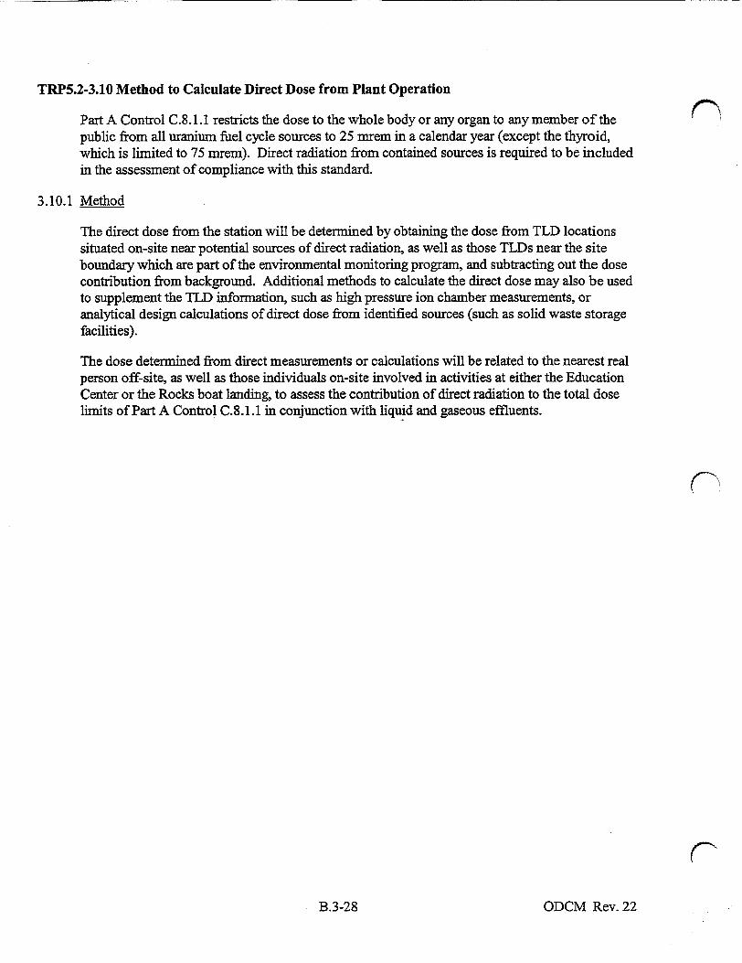
TRP5.2-3.10 Method to Calculate Direct Dose from Plant Operation
Part A Control C.8.1.1 restricts the dose to the whole body or any organ to any member of the public from all uranium fuel cycle sources to 25 mrem in a calendar year (except the thyroid, which is limited to 75 mrem). Direct radiation from contained sources is required to be included in the assessment of compliance with this standard.
3.10.1 Method
The direct dose from the station will be determined by obtaining the dose from TLD locations situated on-site near potential sources of direct radiation, as well as those TLDs near the site boundary which are part of the environmental monitoring program, and subtracting out the dose contribution from background. Additional methods to calculate the direct dose may also be used to supplement the TLD information, such as high pressure ion chamber measurements, or analytical design calculations of direct dose from identified sources (such as solid waste storage facilities).
The dose determined from direct measurements or calculations will be related to the nearest real person off-site, as well as those individuals on-site involved in activities at either the Education Center or the Rocks boat landing, to assess the contribution of direct radiation to the total dose limits of Part A Control C.8.1.1 in conjunction with liquid and gaseous effluents.
(--
ODCM Rev. 22B.3-28

TRP5.2-3.11 Dose Projections
Part A Controls C.6.3.1 and C.7.4.1 require that appropriate portions of liquid and gaseous
radwaste treatment systems, respectively, be used to reduce radioactive effluents when it is
projected that the resulting dose(s) would exceed limits which represent small fractions of the "as
low as reasonably achievable" criteria of Appendix I to 1 OCFR Part 50. The surveillance requirements of these Part A Controls state that dose projections be performed at least once per
31 days when the liquid radwaste treatment systems or gaseous radwaste treatment systems are not being fully utilized.
Since dose assessments are routinely performed at least once per 31 days to account for actual releases, the projected doses shall be determined by comparing the calculated dose from the last (typical of expected operations) completed 31-day period to the appropriate dose limit for use of radwaste equipment, adjusted if appropriate for known or expected differences between past
operational parameters and those anticipated for the next 31 days.
3.11.1 Liquid Dose Proiections
The 31-day liquid dose projections are calculated by the following:
a. Determine the total body Dtd and organ dose Din. (Equations 3-1 and 3-2, respectively) for the last typical completed 31 -day period. The last typical 31-day period should be one without significant identified operational differences from the period being projected to, such as full power operation vs. periods when the plant is shut down. For periods with identified operational differences, skip to subsection 3.11. L.e. below.
b. Calculate the ratio (R1) of the total estimated volume of batch releases expected to be released for the projected period to that actually released in the reference period.
c. Calculate the ratio (R2) of the estimated gross primary coolant activity for the projected period to the average value in the reference period. Use the most recent value of primary coolant activity as the projected value if no trend in decreasing or increasing levels can be determined.
d. Determine the projected dose from:
Total Body: Dtb pr = Dtb . R, . R2
Max. Organ: Dineopr = D.e0 . R, .
e. During periods when significant operational differences are identified, such as shutdowns vs. normal power operations, or when specific treatment components are expected to be
bypassed or out of service for repair or maintenance, the projected dose should be based on an assessment of the expected amount of radioactivity that could be discharged, both through treated and any untreated pathways, over the next 31 days. Specific consideration should be given to effluent streams and treatment systems noted on Figure
B.6- 1. The volume of liquid to be released, the current or projected maximum radioactivity concentration in the effluent streams either prior to treatment or at the point
of release to the environment, and the duration of expected release evaluations should be estimated as part of the projection of offsite dose.
ODCM Rev. 22B.3-29
For these periods outside the bounds of steps 3.1 1.1.a. when significant operational differences exist from the last reference period, the projected dose to the total body Dtb and organ dose Din shall use Equations 3-1 and 3-2, respectively to project dose for each C definable time segment of release evolution and summed over the next 31 days. The radioactive release quantity, Qi, in equations 3-1 and 3-2 represents the estimated quantity of radionuclide "i" estimated to be released over the next 31 days, or during short time periods for defined plant operational evaluations, based on expected volumes, concentrations and treatment options to be applied.
The EMS software can also be used to perform monthly projected dose calculations as described in Appendix C. The methodology applied by EMS in projecting liquid doses is outlined in Section 2.7 of Attachment 4 to Appendix C (EMS Technical Reference Manual).
3.11.2 Gaseous Dose Projections
1. For the gaseous radwaste treatment system, the 31-day dose projections are calculated by the following:
a. Determine the gamma air dose D, (Equation 3-6a), and the beta air dose Dq (Equation 3 -7a) from the last typical 31-day operating period. The last typical 31-day period should be one without significant identified operational differences from the period being projected to, such as full power steady state operation vs. periods when the plant is shutdown. For periods with identified operational differences, skip to subsection 3.11.2.2.e. below.
b. Calculate the ratio (R3) of anticipated number of curies of noble gas to be released from the hydrogen surge tank to the atmosphere over the next 31 days to the number C of curies released in the reference period on which the gamma and beta air doses are based. If no differences between the reference period and the next 31 days can be identified, set R3 to 1.
c. Determine the projected dose from:
Gamma Air: DyfrPrDaR 3
Beta Air: DA.P = Da. R3
2. For the ventilation exhaust treatment system, the critical organ dose from iodines, tritium, and particulates are projected for the next 31 days by the following:
a. Determine the critical organ dose Dc, (Equation 3-8a) from the last typical 3 1-day operating period. (If the limit of Part A Control C.7.4.1.c (i.e., 0.3 mrem in 31 days) is exceeded, the projected controlled area annual total effective dose equivalent from all station sources should be assessed to assure that the 1OCFR20.1301 dose limits to members of the public are not exceeded.)*. The last typical 3 1-day period should be one without significant identified operational differences from the period being projected to, such as full power steady state operation vs. periods when the plant is shutdown. For periods with identified operational differences, skip to subsection 3.11.2.2.e. below.
ODCM Rev. 22B.3-30

b. Calculate the ratio (R4) of anticipated primary coolant dose equivalent 1-131 for the
next 31 days to the average dose equivalent 1-131 level during the reference period.
Use the most current determination of DE 1-131 as the projected value if no trend
can be determined.
c. Calculate the ratio (R5) of anticipated primary system leakage rate to the average
leakage rate during the reference period. Use the current value of the system
leakage as an estimate of the anticipated rate for the next 31 days if no trend can be
determined.
d. Determine the projected dose from:
Critical Organ: Dco pr = D . .R5
e. During periods when significant operational differences are identified, such as
shutdowns vs. normal power operations, or when specific treatment components are
expected to be bypassed or out of service for repair or maintenance, the projected
dose should be based on an assessment of the expected amount of radioactivity that
could be discharged, both through treated and any untreated pathways, over the next
31 days. Specific consideration should be given to effluent streams and treatment
systems noted on Figure B.6-2. The volume or flow rate of gas to be released, the
current or projected maximum radioactivity concentration M'' the effluent streams
either prior to treatment or at the point of release to the environment, and the
duration of expected release evaluations should be estimated as part of the
projection of offsite dose.
For these periods outside the bounds of steps 3.11.2.1 .a or 3.11.2.2.a. when
significant operational differences exist from the last reference period, the projected
air dose from gamma and beta emissions from noble gases (Equations 3-6 and
Equations 3-7, respectively), or from iodines, tritium, and particulates (Equations
3-8) shall use the referenced equations to project dose for each definable time
segment of release evolution and summed over the next 31 days. The radioactive
release quantity, Qi in the dose equations represents the estimated quantity of
radionuclide "i" estimated to be released over the next 3 1 days, or during short time
periods for defined plant operational evaluations, based on expected volumes,
concentrations and treatment options to be applied.
The EMS software can also be used to perform monthly projected dose calculations as described
in Appendix C. The methodology applied by EMS in projecting gaseous dose is outlined in
Section 3.8 of Attachment 4 to Appendix C (EMS Technical Reference Manual).
ODCM Rev. 22B.3-31

*Note: This action is based on the assumption that tritium is the controlling nuclide for whole body exposures through the inhalation pathway. Maximum annual average on-site X/Q's for station effluent release points are approximately 100 times the values used for the site boundary dose calculations. However, the site boundary doses calculated by the ODCM for iodines, tritium, and particulates with half lives greater than 8 days, includes all potential off-site exposure pathways. For tritium, the inhalation pathway only accounts for 10% of the total dose contribution being calculated. As a result, if the monthly calculation indicates that the site boundary maximum organ dose reached 0.3 mrem, the on-site maximum dose due to inhalation would be approximately 3.0 mrem for this period. If this were projected to continue for a year with a 2000 hour occupancy factor applied, the projected inhalation whole body dose would be approximately 8 mrem, or 8% of the 1OCFR20.1301 limit. This is a reasonable trigger value for the need to consider the dose contribution from all station sources to members of the public in controlled areas.
ODCM Rev. 22B.3-32

TRP5.2-3.12 Method to Calculate Total Dose From Plant Operations
ODCM Control C.8.1.1 restricts the annual dose to the whole body or any organ of a member of
the public from all uranium fuel cycle sources (including direct radiation) to 25 mrem (except the
thyroid, which is limited to 75 mrem). These cumulative dose contribution limits from liquids
and gaseous effluents, and direct radiation, implement the Environmental Protection Agency
(EPA) 40CFR1 90, "Environmental Standards for the Uranium Fuel Cycle."
3.12.1 Method
Compliance with the Seabrook Station Effluent Controls dose objectives for the maximum
individual, as calculated by the methods described in sections B.3.2, B.3.3, B.3.7, B.3.8, B.3.9 of
the ODCM also demonstrates compliance with the EPA limits to any member of the public. This
indirect determination of compliance is based on the fact that the Effluent Control liquid and
gaseous dose objectives are taken from 1OCFRS0, Appendix I, and represent lower values than
the 40CFR190 dose limits. Direct radiation dose from contained sources is not expected to be a
significant contributor to the total dose to areas beyond the site boundary. If the operational dose
objectives in the Seabrook ODCM Effluent Controls C.6.2.1.a, C.6.2.1.b, C.7.2.1.a, C.7.2.1.b,
C.7.3.l .a, or C.7.3.1.b are determined to be exceeded by a factor of two, a Special Report must
be prepared. The purpose of this Special Report is to determine by direct assessment if the
cumulative dose (calendar year) to any member of the public (real individual) from all sources is
within the limits of the Total Dose Control C.8.1.1.
In addition, section A.10.2, "Annual Radioactive Effluent Release Report," requires that an
assessment of radiation doses to the likely most exposed member of the public from all effluent
and direct radiation sources be included for the previous calendar year to show compliance with
40CFR190.
When required, the total dose to a member of the public will be calculated for all significant
effluent release points for all real pathways, including direct radiation. Only effluent releases
from Seabrook Station need be considered since no other uranium fuel cycle facilities exist
within five miles. EPA has determined that for fuel cycle facilities separated by more than five
miles, their contribution to each other's total dose would not be significant and cause dose
Standard for the Uranium Fuel Cycle to be exceeded. The calculations will be based on the
liquid and gaseous Methods II dose models as described in Section B.3, including usage factors
and other documented site-specific parameters reflecting realistic assumptions, where
appropriate. The liquid and gaseous effluent Method II models are derived from the methods
given in Regulatory Guide 1.109, Rev. 1, October 1977.
The direct radiation component from the facility can be determined using environmental TLD
results as noted in Section B.3.10.1 (or alternately, high pressure ion chamber measurements or
analytical design calculations for estimating the direct radiation dose from identified contained
radioactive sources within the facility).
ODCM Rev. 22B.3-33

TRP5.2-4.0 RADIOLOGICAL ENVIRONMENTAL MONITORING PROGRAM
The radiological environmental monitoring stations are listed in Table B.4-1. The locations of
the stations with respect to the Seabrook Station are shown on the maps in Figures B.4-1 to
B.4-6.
Direct radiation measurements are analyzed at the station. All other radiological analyses for
environmental samples are performed at a contractor laboratory. The contractor laboratory
participates in an Interlaboratory Comparison Program for all relevant species in an aqueous
(water) matrix. An independent vendor (Analytics) supplies the remaining cross check samples.
These samples are presented on an air filter and in milk and water matrices.
Pursuant to Part A Surveillance S.9.2.1, the land use census will be conducted "during the
growing season" at least once per 12 months. The growing season is defined, for the purposes of
the land use census, as the period from June 1 to October 1. The method to be used for
conducting the census will consist of one or more of the following, as appropriate: door-to-door
survey, visual inspection from roadside, aerial survey, or consulting with local agricultural
authorities.
Technical Specification 6.8.1.3 and Part A, Section 10.1 of the ODCM require that the results of
the Radiological Environmental Monitoring Program be summarized in the Annual Radiological
Environmental Operating Report "in the format of the table in the Radiological Assessment
Branch Technical Position, Revision 1, 1979." The general table format will be used with one
exception and one clarification, as follows. The mean and range values will be based not upon
detectable measurements only, as specified in the NRC Branch Technical Position, but upon all
measurements. This will prevent the positive bias associated with the calculation of the mean
and range based upon detectable measurements only. Secondly, the Lower Limit of Detection
column will specify the LLD required by ODCM Table A.9.1-2 for that radionuclide and sample
medium.
ODCM Rev. 21B.4-1

TABLE B.4-1 RADIOLOGICAL ENVIRONMENTAL MONITORING STATIONS(a)
Exposure Pathway and/or Sample
Sample Location and Designated Code
Distance From Unit 1
Containment (kim)
Direction From the Plant
1. AIRBORNE (Particulate and Radioiodine)
AP/CF-01 PSNH Barge Landing Area AP/CF-02 Harbor Road AP/CF-03 SW Boundary AP/CF-04 W. Boundary AP/CF-05 Winnacunnet H.S.(b) AP/CF-06 Georgetown
Substation (Control) AP/CF-08 E&H Substation(b)
2. WATERBORNE
a. Surface
b. Sediment
WS-01 WS-51
SE-02 SE-07 SE-08 SE-52 SE-57
Hampton-Discharge Area Ipswich Bay (Control)
Hampton-Discharge Area0') Hampton Beach(b) Seabrook Beach Ipswich Bay (Control)(b) Plum Island Beach (Control)(b)
3. INGESTION
TM-04 TM-09 TM-15 TM-16 TM-20 TM-21
Salisbury, MA Hampton, NH Hampton Falls, NH°b) Kensington, NHi(b)
Rowley, MA (Control) North Andover, MA0b)
b. Fish and Invertebrates(c)
FH-03 FH-53 HA-04 HA-54 MU-06 MU-09 MU-56 MU-59
Hampton - Discharge Area Ipswich Bay (Control) Hampton - Discharge Area Ipswich Bay (Control) Hampton - Discharge Area Hampton Harbor(b) Ipswich Bay (Control) Plum Island0')
ODCM Rev. 21
2.6 2.5 1.0 1.2 4.0
22.6
3.4
ESE E SW W NNE SSW
SSE
E SSE
E E ESE SSE SSE
5.3 16.9
5.3 3.1 3.2
16.9 15.9
a. Milk 5.3 5.3 6.9 7.6
17.0 20.8
SW NNW NW WNW S SW
4.5 16.4 5.5
17.2 5.2 2.6
17.4 15.8
ESE SSE E SSE E E SSE SSE
B.4-2

TABLE B.4-1 RADIOLOGICAL ENVIRONMENTAL MONITORING STATIONS(a)
(Continued)
Exposure Pathway Sample Location Distance From Direction From and/or Sample and Designated Code Unit 1 the Plant
Containment (Iam)
4. DIRECT RADIATION
TL-1 Brimmer's Lane, .97 N Hampton Falls
TL-2 Landing Rd., Hampton 3.0 NNE TL-3 Glade Path, Hampton 2.9 NE
Beach TL-4 Island Path, Hampton 2.3 ENE
Beach TL-5 Harbor Rd., Hampton 2.6 E
Beach TL-6 PSNH Barge Landing 2.7 ESE
Area TL-7 Cross Rd., Seabrook Beach 2.6 SE TL-8 Farm Lane, Seabrook 1.3 SSE TL-9 Farm Lane, Seabrook 1.3 S TL-10 Site Boundary Fence 1.2 SSW TL-1l Site Boundary Fence 1.0 SW TL-12 Site Boundary Fence 1.2 WSW TL-13 Inside Site Boundary 1.2 W TL-14 Trailer Park, Seabrook 1.3 WNW TL-15 Brimmer's Lane, 1.4 NW
Hampton Falls TL-16 Brimmer's Lane, 1.2 NNW
Hampton Falls TL-17 South Rd., N. Hampton 7.8 N TL-18 Mill Rd., N. Hampton 7.6 NNE TL-19 Appledore Ave., 7.7 NE
N. Hampton TL-20 Ashworth Ave., 3.2 ENE
Hampton Beach TL-21 Route 1A, Seabrook Beach 3.7 SE TL-22 Cable Ave., 7.6 SSE
Salisbury Beach TL-23 Ferry Rd., Salisbury 8.1 S TL-24 Ferry Lots Lane, 7.2 SSW
Salisbury TL-25 Elm St., Amesbury 7.6 SW TL-26 Route 107A, Amesbury 8.1 WSW
ODCM Rev. 21B.4-3

TABLE B.4-1 RADIOLOGICAL ENVIRONMENTAL MONITORING STATIONSc(a)
(Continued)
Exposure Pathway Sample Location Distance From Direction From and/or Sample and Designated Code Unit 1 the Plant
Containment (km)
TL-27 Highland St., S. Hampton 7.5 W TL-28 Route 150, Kensington 7.5 WNW TL-29 Frying Pan Lane, 7.2 NW
Hampton Falls TL-30 Route 27, Hampton 7.6 NNW TL-31 Alumni Drive, Hampton 3.8 NNE TL-32 Seabrook Elementary School 2.0 S TL-33 Dock Area, Newburyport 9.8 S TL-34 Bow St., Exeter 12.0 NW TL-35 Lincoln Ackerman School 2.3 NNW TL-36 Route 97, Georgetown 22.6 SSW
(Control) TL-37 Plaistow, NH (Control) 21.5 WSW TL-38 Hampstead, NH (Control) 27.7 W TL-39 Fremont, NH (Control) 27.0 WNW TL-40 Newmarket, NH (Control) 21.6 NNW TL-41 Portsmouth, Nil, (Control)(b) 21.0 NNE TL-42 Ipswich, MA (Control)() 22.8 SSE
(a) Sample locations are shown on Figures B.4-1 to B.4-6.
(b) This sample location is not required by monitoring program defined in Part A of ODCM; program requirements specified in Part A do not apply to samples taken at this location.
(c) Samples will be collected pursuant to ODCM Table A.9.1-1. Samples are not required from all stations listed during any sampling interval (FH = Fish; HA = Lobsters; MU = Mussels ). Table A.9. 1-1 specifies that "one sample of three commercially and recreationally important species" be collected in the vicinity of the plant discharge area, with similar species being collected at a control location. (This wording is consistent with the NRC Final Environmental Statement for Seabrook Station.) Since the discharge area is off-shore, there is a great number of fish species that could be considered commercially or recreationally important. Some are migratory (such as striped bass), making them less desirable as an indicator of plant-related radioactivity. Some pelagic species (such as herring and mackerel) tend to school and wander throughout a large area, sometimes making catches of significant size difficult to obtain. Since the collection of all species would be difficult or impossible, and would provide unnecessary redundancy in terms of monitoring important pathways to man, three fish and invertebrate species have been specified as a minimum requirement. Samples may include marine fauna such as lobsters, clams, mussels, and bottom-dwelling fish, such as flounder or hake. Several similar species may be grouped together into one sample if sufficient sample mass for a single species is not available after a reasonable effort has been made (e.g., yellowtail flounder and winter flounder).
ODCM Rev. 21B.4-4

FIGURE B.4-1
RADIOLOGICAL ENVIRONMENTAL MONITORING LOCATIONS WITHIN 4 KILOMETERS OF SEABROOK STATION
ODCM Rev. 21B.4-5

FIGURE B.4-2 RADIOLOGICAL ENVIRONMENTAL MONITORING LOCATIONS
BETWEEN 4 KILOMETERS AND 12 KILOMETERS FROM SEABROOK STATION 1
a 5
KILOME'ERS
(J N
RTE REACH
TM----5
SEE ENLAME4WN IX FIGURE 8. 4- 1 ApCpO
TM- •1 2-9 ' •4-TON Ma
: "r~l !SE-07
ODCM Rev. 21B.4-6
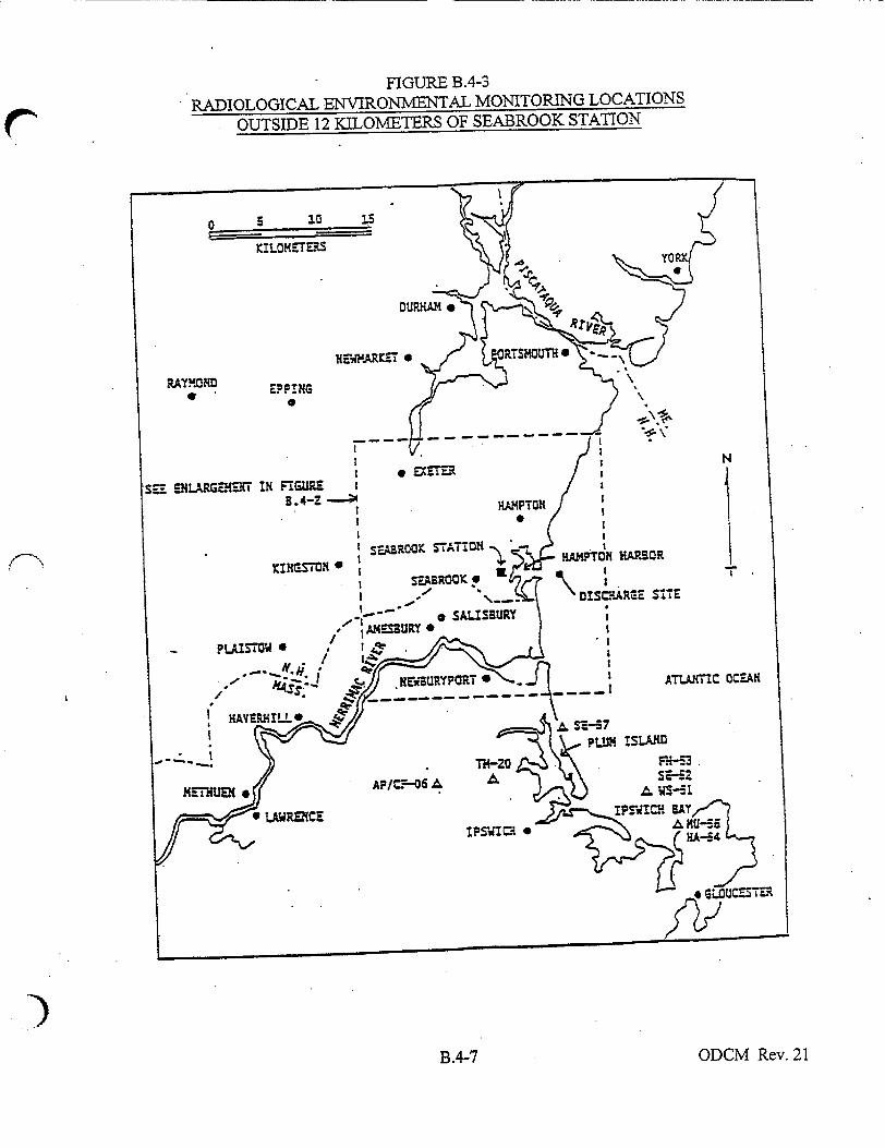
FIGURE B.4-3
RADIOLOGICAL ENVIRONMENTAL MONITORING LOCATIONS
OUTSIDE 12 KILOMETERS OF SEABROOK STATION
ODCM Rev. 21B.4-7

FIGURE B.4-4 DIRECT RADIATION MONITORING LOCATIONS WITHIN
4 KILOMETERS OF SEABROOK STATION
ODCM Rev. 21B.4-8

FIGURE B.4-5
DIRECT RADIATION MONITORING LOCATIONS BETWEEN
4 KILOMETERS AND 12 KILOOMETERS FROM SEABROOK STATION
ODCM Rev. 21B.4-9

FIGURE B.4-6 DIRECT RADIATION MONITORING LOCATIONS OUTSIDE
12 KILOMETERS OF SEABROOK STATION )
NNW N N s. 10 - a
FREMONRT!T P=RTS. . .
*i SALSURY
SIT. ATLJAV C CC:-AN
)ODCM Rev. 21B.4-10
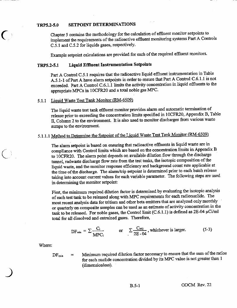
SETPOINT DETERMINATIONS
Chapter 5 contains the methodology for the calculation of effluent monitor setpoints to
implement the requirements of the radioactive effluent monitoring systems Part A Controls
C.5.1 and C.5.2 for liquids gases, respectively.
Example setpoint calculations are provided for each of the required effluent monitors.
TRP5.2-5.1 Liquid Effluent Instrumentation Setpoints
Part A Control C.5.1 requires that the radioactive liquid effluent instrumentation in Table
A.5.1-1 of Part A have alarm setpoints in order to ensure that Part A Control C.6.1.1 is not
exceeded. Part A Control C.6.1.1 limits the activity concentration in liquid effluents to the
appropriate MPCs in 10CFR20 and a total noble gas MPC.
5.1.1 Liquid Waste Test Tank Monitor (RM-6509)
The liquid waste test tank effluent monitor provides alarm and automatic termination of
release prior to exceeding the concentration limits specified in 1OCFR20, Appendix B, Table
II, Column 2 to the environment. It is also used to monitor discharges from various waste
sumps to the environment.
5.1.1.1 Method to Determine the Setpoint of the Liquid Waste Test Tank Monitor (RM-6509)
The alarm setpoint is based on ensuring that radioactive effluents in liquid waste are in
compliance with Control limits which are based on the concentration limits in Appendix B
to 10CFR20. The alarm point depends on available dilution flow through the discharge
tunnel, radwaste discharge flow rate from the test tanks, the isotopic composition of the
liquid waste, and the monitor response efficiency and background count rate applicable at
the time of the discharge. The alarm/trip setpoint is determined prior to each batch release
taking into account current values for each variable parameter. The following steps are used
in determining the monitor setpoint:
First, the minimum required dilution factor is determined by evaluating the isotopic analysis
of each test tank to be released along with MPC requirements for each radionuclide. The
most recent analysis data for tritium and other beta emitters that are analyzed only monthly
or quarterly on composite samples can be used as an estimate of activity concentration in the
tank to be released. For noble gases, the Control limit (C.6.1.1) is defined as 2E-04 ACi/ml
total for all dissolved and entrained gases. Therefore,
DFi = - Ci or Z CN' , whichever is larger. (5-3)
MPCi 2E -04
Where:
DF,. = Minimum required dilution factor necessary to ensure that the sum of the ratios
for each nuclide concentration divided by its MPC value is not greater than 1 (dimensionless).
ODCM Rev. 22
TRP5.2-5.0
B.5-1

Ci Activity concentration of each radionuclide "i" (except noble gases) determined to be in the test tank (tCi/ml). This includes tritium and other non gamma emitting isotopes either measured or estimated from the most recent composite analysis.
C-9 The sum of all dissolved and entrained noble gases identified in each test tank (jCi/mi).
MPCi The concentration limit (above background) at point of discharge to the environment for radionuclide "i" taken from 1 OCFR20, Appendix B, Table I, Column 2 (pCi/ml) for all nuclides other than noble gases.
See ODCM, Appendix B, for a listing. In the event that no activity is expected to be discharged, or can be measured in the system, the liquid monitor setpoint should be based on the most restrictive MPC for an "unidentified" mixture or a mixture known not to contain certain radionuclides as given in 1 CFR20, Appendix B, notes.
2E-04 = The total dissolved and entrained noble gas Technical Specification concentration limit in liquid effluents from the plant (ltCi/ml).
Next, the available dilution flow through the discharge tunnel (Fd), or a conservative estimate for it, is divided by the minimum dilution factor (DF.in) to determine the maximum allowable discharge flow rate (Fm) that the test tanks could be released at without exceeding the MPC limits, assuming no additional radioactive flow paths are discharging at the time of release of the test tanks. Therefore,
FmaT- Fd
DFm
Where:
F,. The maximum allowable discharge flow rate from the test tank past the monitor which would equate to the Control concentration limit for the radioactivity mixture determined to be in the test tank (gpm).
Fd The actual or conservative estimate of the flow rate out of the discharge tunnel (gpm).
The selection of the actual discharge flow rate (Fm) from the test tanks compared to the maximum allowable discharge rate must satisfy the following:
Fm < Fraxxftt
ODCM Rev. 22B.5-2

where the ft represents an administrative fraction of the maximum allowable discharge flow
from the test tanks. This fraction provides additional margin in meeting MPC limits for non
gamma emitters (such as tritium) at the discharge point to the ocean when other flow paths
may contribute to the total site release at the time of tank discharges and minimum dilution flow conditions exist.
With the above conditions on discharge and dilution flow rates satisfied, the alarm/trip
setpoint for the monitor which corresponds to the maximum allowable concentration at the
point of discharge (conservatively assuming that any change in the expected gamma activity
in a test tank is also reflective of the same change in non gamma emitters, such as tritium) is determined as follows:
Rft =fl x Fd xzC~i (5-1)
Fm X DFm,
Where:
Rsetpoint The maximum allowable alarm/trip setpoint for an instrument response (gCi/ml) that ensures the limiting concentration at the point of discharge is not exceeded.
f- The fraction of the total contribution of MPC at the discharge point to be associated with the test tank effluent pathway, where f2, f3, and f4
are the fractions for the Turbine Building Sump, Steam Generator Blowdown, and Primary Component Cooling pathways contributions to the total, respectively (f1+f2+f3+f4 < 1). Each of the fractions may
be conservatively set administratively such that the sum of the fractions is less than 1. This additional margin can be used to account for the uncertainty in setpoint parameters such as estimated concentration of non gamma emitters that are based on previous composite analyses of the waste stream.
5.1.1.2 Liquid Waste Test Tank Monitor Setpoint Example
The radioactivity concentration of each radionuclide, Ci, in the waste test tank is determined
by analysis of a representative grab sample obtained at the radwaste sample sink, and analyzed prior to release for gamma emitters, or as part of a composite analysis for non
gamma emitters. This setpoint example is based on the following data:
Ci (9Ci/mI) MPCi (gCi/mi)
Cs-134 2.15E-05 9E-06
Cs-137 7.48E-05 2E-05
Co-60 2.56E-05 3E-05
H-3 1.50E-01 3E-03
ODCM Rev. 22B.5-3

The minimum required dilution factor for this mix of radionuclides is:
DF. - Ci _ 2.15E-05 7.48E-05 + 2.56E-05 + 1.50E-01 = 57 MPCI 9E - 06 2E - 05 3E-05 3E-03
The release flow rate (Fro) from the waste test tanks can be set between 10 and 150 gpm. The cooling water tunnel discharge dilution flow rate (Fd) can typically vary from approximately 8,800 to 412,000 gpm depending on the operating status of the plant. In this example, if the dilution flow (Fd) is taken as 412,000 gpm, the maximum allowable discharge rate (FEx) is:
Fd F.a - F
DFm 412,000 = gpm
57 = 7228 gpm
With the selected release rate from the test tank set at 150 gpm, and the administrative flow fraction (ft) assumed in this example to be 0.7, the condition for the Technical Specification concentration limits is met since:
Fm (equal to 150) < F. (equal to 7228 gpm) x ftt (set at 0.7)
150 < 5060
and the monitor response due to the mix of the gamma emitters is:
i Cyi (ACi/ml)
Cs-134 2.15E-05
Cs-137 7.48E-05
Co-60 2.56E-05
C= 1.22E -04,uCi/ml
Under these conditions, the alarm/trip setpoint for the liquid radwaste discharge monitor is:
R.•i,= fi x Fd x XCYi (5-1)
Fm x DF,
jiCi/ml (0) (0) ACi/ml 412,000
0.4 = 0.41x x 1.22E - 04 150 x 57
= 2.35E - 03 jiCi/ml
ODCM Rev. 22B.5-4

In this example, the alarm/trip setpoint of the liquid radwaste discharge monitor can be put at
2.35E-03 gCi/ml above background. For the example, it is assumed that the test tank release
pathway will be limited to only 40% of the total site discharge allowable concentration.
5.1.2 Turbine Building Drains Liquid Effluent Monitor (RM-6521)
The Turbine Building drains liquid effluent monitor continuously monitors the Turbine
Building sump effluent line. The only sources to the Sump Effluent System are from the
secondary steam system. Activity is expected in the Turbine Building Sump Effluent System
only if a significant primary-to-secondary leak is present. If a primary-to-secondary leak is
present, the activity in the sump effluent system would be comprised of only those
radionuclides found in the secondary system, with reduced activity from decay and dilution.
The Turbine Building drains liquid effluent monitor provides alarm and automatic
termination of release prior to exceeding the concentration limits specified in 1OCFR20, Appendix B, Table II, Column 2 to the environment. The alarm setpoint for this monitor will
be determined using the same method as that of the liquid waste test tank monitor if the total
sump activity is greater than 10 percent of MPC, as determined by the most recent grab
sample isotopic analysis. If the total activity is less than 10 percent of MPC, the setpoints of RM-6521 are calculated as follows:
High Trip Monitor Setpoint (pCi/ml) f2 (DF') ("unidentified mix MPC" (itCi/ml)) (5-21)
where:
Circulating water flow rate (gpm)
DF' - Flow rate pass- monitor (gpm)
unidentified mix MPC = most restrictive MPC value (.LCi/ml) for an unidentified mixture or a mixture known not to contain certain radionuclides as given in 1 OCFR20, Appendix B, Notes.
f2 1 - (f, + f3 + 4); where the f values are described above.
In addition, a warning alarm setpoint can be determined by multiplying the high trip alarm point by an
administratively selected fraction (as an example, 0.25).
Warning Alarm I High Trip
Monitor Setpoint ,Monitor Sepoint) (0.25)
(puCi/mnl)j
ODCM Rev. 22B.5-5

5.1.3 Steam Generator Blowdown Liquid Sample Monitor (RM-6519)
The steam generator blowdown liquid sample monitor is used to detect abnormal activity concentrations in the steam generator blowdown flash tank liquid discharge.
The alarm setpoint for the steam generator blowdown liquid sample monitor, when liquid is to be discharged from the site, will be determined using the same approach as the Turbine Building drains liquid effluent monitor.
For any liquid monitor, in the event that no activity is expected to be discharged, or can be measured in the system, the liquid monitor setpoint should be based on the most restrictive MPC for an "unidentified" mixture or a mixture known not to contain certain radionuclides given in 10CFR20, Appendix B notes.
5.1.4 PCCW Head Tank Rate-of-Change Alarm Setpoint
A rate-of-change alarm on the liquid level in the Primary Component Cooling Water (PCCW) head tank will work in conjunction with the PCCW radiation monitor to alert the operator in the Main Control Room of a leak to the Service Water System from the PCCW System. For the rate-of-change alarm, a setpoint is selected based on detection of an activity level equivalent to 10-8 gtCi/ml in the discharge of the Service Water System. The activity in the PCCW is determined in accordance with the liquid sampling and analysis program described in Part A, Table A.6 1-1 of the ODCM and is used to determine the setpoint.
The rate-of-change alarm setpoint is calculated from:
RCý, =lxl0 8 . SWF & 1 (5-23) PCC
(gal) fluCi ~gal' ( ml)
hrm ) hr ) LjPci)
where:
RCset The setpoint for the PCCW head tank rate-of-change alarm (in gallons per hour).
Ixl0 8 = The minimum detectable activity level in the Service Water System due to a
PCCW to SWS leak (gCi/ml).
SWF = Service Water System flow rate (in gallons per hour).
PCC = Primary Component Cooling Water measured (decay corrected) gross radioactivity level (jiCi/mi).
ODCM Rev. 22B.5-6

As an example, assume a PCCW activity concentration of lxl0-5 jiCi/ml with a service
water flow rate of only 80 percent of the normal flow of 21,000 gpm. The rate-of-change
setpoint is then:
RtC = 1x10 9Ci 0 1.0xl0I gph (I/lxl0s .9Ci Il ml"
RCt = 1000 gph
As a result, for other PCCW activities, the RCset which would also relate to a detection of a
minimum service water concentration of lxl0"8 gCi/ml can be found from:
lxl0= 5 xo uCi/mlx 1000 gph (5-24)
PCC
5.1.5 PCCW Radiation Monitor
The PCCW radiation monitor will alert the operator in the Main Control Room of a leak to the
PCCW System from a radioactively contaminated system.
The PCCW radiation monitor alarm is based on a trend of radiation levels in the PCCW
System. The background radiation of the PCCW is determined by evaluating the radiation
levels over a finite time period. The alert alarm setpoint is set at 1.5 x background, and the
high alarm setpoint is set at 2 x background, per Technical Specification Table 3.3-6.
ODCM Rev. 22B.5-7

TRP5.2-5.2 Gaseous Effluent Instrumentation Setpoints
Part A Control C.5.2 requires that the radioactive gaseous effluent instrumentation in Table A.5.2-1 of Part A have their alarm setpoints set to insure that Part A Control C.7.1.1 is not exceeded.
5.2.1 Plant Vent Wide-Range Gas Monitors (RM-6528-1,2 and 3)
The plant vent wide-range gas monitors are shown on Figure B.6-2.
5.2.1.1 Method to Determine the Setpoint of the Plant Vent Wide Range Gas Monitors (RM-6528-1,2 and 3)
The maximum allowable setpoint for the plant vent wide-range gas monitor (readout response in jtCi/sec) is set by limiting the off-site noble gas dose rate to the total body or to the skin, and denoted Rsetpoint- Rsetpoint is the lesser of:
R =-5s8 8 -1 fV (5-5) DFB.
Y Ci/sec =(.mre m- ) ( pCi- yr3) yr- pCi- sec trer-m
and:
1 R = 3,000 --- " f, (5-6) DF'c
____ 9 Ci- yr Y Ci/sec=( ) ( yr mrem-sec
where:
Rtb Response of the monitor at the limiting total body dose rate (ptCi/sec)
500 (mrem-/ Ci- m3
588 = (1E+06) (8.5E-07) yr-pCi-sec
500 = The offsite limiting total body dose rate (mrem/yr) from all release points
1E+06 = Number of pCi per AtCi (pCi/AtCi)
8.5E-07 = [X/Q]7, maximum off-site long-term average gamma atmospheric dispersion factor for primary vent stack releases (sec/m3)
ODCM Rev. 22B.5-8

--- Composite total body dose factor (mrem-m3/pCi-yr)
- QDFBi (5-7)
f" The fraction of the offsite limiting total body dose rate to be administratively assigned to the plant vent (fv < 1 -fg, where fg is the fraction of the limiting dose rate to be assigned to monitored ground level releases)
= iThe relative release rate of noble gas "i" in the mixture, for each noble gas identified or postulated to be in the off-gas (jtCi/sec)
DFBi = Total body dose factor (see Table B.1-10) (mrem-m3/pCi-yr)
Rs, = Response of the monitor at the limiting skin dose rate (jiCi/sec)
3,000 = The offsite limiting skin dose rate (mrem/yr)
DF'C = Composite skin dose factor (mrem-sec/ptCi-yr)
-X DF' , (5-8)
DF'i(e) Combined skin dose factor for elevated release point (see Table B. 1-10) (mrem-sec/jtCi-yr)
5.2.1.2 Plant Vent Wide Range Gas Monitor Setpoint Example for Limiting Case
The following setpoint example for the plant vent wide range gas monitors demonstrates the
use of equations 5-5 and 5-6 for determining setpoints. Evaluations of potential releases rates
associated with the limiting offsite dose rates (Control C.7. 1.1 .a) have been made considering
different noble gas mixes related to normal operations, observed periods with fuel defects,
and potential UFSAR accident conditions. The bounding noble gas mix case for setpoint
alarm indications was found to be related to projected fuel gap activity at the time of
shutdown from power operations (UFSAR Table 15.7-20). By setting the maximum alarm
setpoint in accordance with this assumed mix, other potential or realistic release conditions
will not create an effluent discharge at or above the limiting offsite dose rates without the monitor going into alarm.
ODCM Rev. 22
DFBC
B.5-9

This limiting setpoint example is based on the following data (see Table B. 1-10 for DFBi(e) and DF'i(e)):
Qi ( ci) sec
2.52E+02
7.90E+01
1.15E+02
4.49E+01
6.82E+01
3.23E+02
4.13E+00
1.15E+00
4.67E+01
6.64E+01
DFBi
mrem-m3
pCi- yr
8.83E-03
5.92E-03
1.47E-02
1.1 7E-03
1.81E-03
2.94E-04
1.61E-05
9.15E-05
2.51E-04
3.12E-03
ODCM Rev. 22
i
Xe-138
Kr-87
Kr-88
Kr-85m
Xe-135
Xe-133
Kr-85
Xe-131m
Xe-133m
Xe-135m
DF'i(e)
mrem- sec
,Ci- yr
1.20E-02
1.38E-02
1.62E-02
2.35E-03
3.33E-03
5.83E-04
1.11E-03
5.37E-04
1.12E-03
3.74E-03
I
B.5-10

DFB. ý QjDFBi(57
Z Q, DFB, (2.52E+02)(8.83E-03) +(7.90E+01)(5.92E-03) +(1 .15E+02) (1 .47E-02)
+ (4.49E+01 )(1 .1 7E-03) + (6.82E+01 )(1 .8 1E-03) + (3 .23E+i02) (2.94E-04)
+ (4.1 3E+O0)(1 .61E-05) + (1.1 5E+00)(9. 1 E-OS) + (4.67E+0 1) (2.5 1E-04)
+ (6.64E+01) (3.12E-03)
=4.86E+00 (jiCi-mrem-m3/sec-pCi-yr)
~~ ~ = 2.52E+02 +7.90E+O1 +1.15E+02 +4.49E+O1 +6.82E+O1
+ 3.23E+02 + 4.14E+00 + 1.16E+00 + 4.67E+01 + 6.64E+01
- 1OOE+03 p.Cilsec
4.86 E+ 00 DFB, 1.00OE+03
-4.86E-03 (mrem-m3/pCi-yr)
and therefore:
&tb = 588 f, (5-5)
= (588) 1 0.7 (4.86 E- 03)
= 8.47E+04 p.Cilsec
B.5-11ODCM Rev. 22B.5-11

and next;
DF - Y j DFQ' (5-8)
, DF' = (2.52E+02)(1.20E-02) + (7.90E+01)(1.38E-02) + (1.15E+02) (1.62E-02)
+ (4.49E+01)(2.35E-03) + (6.82E+01)(3.33E-03) + (3.23E+02) (5.83E-04)
+ (4.13E+00)(1.11E-03) + (1.15E+00)(5.37E-04) + (4.67E+01) (1.12E-03)
+ (6.64E+01) (3.74E-03)
- 6.80E+00 (gCi-mrem-sec/sec-gCi-yr)
6.80E + 00 DF'C = 1.OOE + 03
= 6.80E - 03 (mrem - sec/4Ci - yr)
and therefore: ,
Rski = 3,000 1 f" (5-6)
11 DF.'
= (3,000) ) 0.7 6.80E -03
= 3.09E+05 ptCi/sec
The setpoint Rsetpint, is the lesser of RP, and Rskin. For the limiting noble gas mixture, Rtb is less than Rskin, indicating that the total body dose rate is more restrictive. Therefore, the plant vent wide-range gas monitor should be set at no more than 8.47E+04 gCi/sec above background, or at some administrative fraction of the above value.
CODCM Rev. 22B.5-12

5.2.2 Waste Gas System Monitors (RM-6504 and RM-6503)
Process radiation monitors in the waste gas system provide operational information on the performance of the system before its discharge is combined and diluted with other gas flows routed to the plant vent for release to the environment.
The setpoints for the waste gas system monitors are administratively set as small multiples of the expected activity concentration to provide operational control over unexpected changes in gas discharges from the system. Typically, the alert alarm setpoint for both monitors is placed at 1.5 times the expected activity concentration passing the monitor, with the high alarm trip set at 2.0 times the expected concentration flow.
Under all conditions, the maximum allowable alarm trip shall not exceed a concentration equivalent to 62.5 ptCi/cm 3. This concentration limit, based on system design flow of 1.2 cfm, assures that any release from the waste gas system to the plant vent will not exceed the site boundary dose rate limits of Part A Control C.7.1.1.a.
5.2.3 Main Condenser Air Evacuation Monitor (RM-6505)
The process radiation monitor on the main condenser air evacuation system provides operational information about the air being discharged. The discharge typically occurs either directly from the turbine building during start up (hogging mode) or through the plant vent during normal operations. During maintenance activities or other temporary operational conditions, discharges to the turbine roof may also occur. This process monitor is also used as an indicator of potential releases from the Turbine Gland Seal Condenser exhaust. Early indications of a potential release (i.e., monitor count rate at twice the normal background) should be evaluated by collecting a grab sample of the exhausts from both the main condenser and the Turbine Gland Seal Condenser.
The operational setpoints for the air evacuation monitor are administratively set as small multiples of the expected background response of the detector to provide operational control over unexpected changes in the activity discharged from the system. Typically, the alert setpoint is 1.5 times background, with the high alarm set at 2 times background.
Maximum allowable setpoint determinations assure that the site boundary dose rate limits of Part A Control C.7.1.1.a will not be exceeded. For atypical air evacuation detector efficiency of 6.OE+05 cpm-cm3/gtCi, flow rates of 10 to 50 cfm and 10,000 cfm for the normal and hogging modes of operation, respectively, and assuming that all the response is due to the most restrictive noble gas mixture associated with fuel gap activity inventory at the end of power operations (same mixture as used for the limiting mixture for the plant vent Wide Range Gas Monitor setpoint given in section 5.2.1.2), the following examples illustrate the calculation of the limiting setpoint for different operational conditions.
ODCM Rev. 22B.5-13

Case 1: For start-up operations (i.e., 10,000 cfrn hogging flow to the Turbine Building roof), the maximum allowable alarm setpoint is calculated as:
RA= 147 1 f9 fgland
DFBc
where:
RA Release rate equivalent to the assigned fraction of the limiting offsite total body dose rate (uCi/sec)
147 500 (mrem- uCi -m•3
(1E + 06) (3.4E - 06) yr - pCi - sec
500 = The site boundary limiting total body dose rate (mrem/yr) from all release
points
1E+06 = Number of pCi per uCi (pCi/uCi)
3.4E-06 = Maximum off-site long-term average gamma atmospheric dispersion factor for ground level releases (sec/m2 )
DFBC Composite total body dose factor (defined for the WRGM in Section 5.2.1.2 to be equal to 4.86E-03 [mrem-m 3 /pCi-yr] for the limiting fuel gap activity mix)
fg The fraction of the site boundary total body dose rate limit to be administratively assigned to monitored ground level releases (for this illustration = 0.3) such that the combination of the plant vent fraction (fQ) and ground fraction (fg) is less than or equal to 1 (fg < 1 - fQ).
fgland Release reduction factor to be administratively assigned to account for potential unmonitored contributions from the Turbine Gland Seal Condenser exhaust (for this illustration = 0.7).
1 RAE = 147 (0.3) (0.7) 4.86E - 03
= 6.36E+03 uCi/sec release rate limit
and for the 10,000 cfin (4.72E+06 cm3/sec) exhaust flow, the count rate response of the air evacuation monitor would be:
Monitor Response - RA 6.0E+05 cpm-cm3/uCi 4.72E + 06cm3 / sec
= (6.36E+03) (6.OE+05) / (4.72E+06)
= 8.07E+02 cpm
ODCM Rev. 22B.5-14

Case 2: As an extension of Case 1 which assumed the full startup hogging flow was
released to the Turbine Building roof, maintenance requirements could direct
normal operating main condenser offgas flow (assume 50 cfmn or equivalent
2.36E+04 cm3/sec) to the Turbine Building Roof (ground level release point)
instead of the elevated main plant vent. In this situation, the same release rate
limit as calculated above (i.e., 6.36E+03 uCi/sec) would apply. However, the
reduced gas flow from 10,000 efin down to 50 cfm would permit a higher alarm
setpoint to be used.
Monitor Response R 6.0E+05 cpm-cm3/uCi
2.36E + 04cm3 /sec
= (6.36E+03) (6.OE+05) / (2.36E+04)
= 1.62E+05 cpm
Case 3: For normal operations which direct main condenser offgas flow (assume 50 cfm or
equivalent 2.36E+04 cm3/sec) to be released to the atmosphere via the main plant vent, the maximum allowable alarm setpoint would be:
RAE =588 1 fv fgland
DFBC
where:
RAE = Release rate equivalent to the assigned fraction of the limiting offsite total body dose rate (uCi/sec)
500 mrem -uCi -m 3)
(1E + 06) (8.5E - 07) yr - pCi - sec
5.8E-07 Maximum off-site long-term average gamma atmospheric dispersion factor for elevated (mixed mode) releases (see/m2)
DFBc Composite total body dose factor (defined for the WRGM in Section 5.2.1.2 to be equal to 4.86E-03 [mrem-m3 /pCi-yr] for the limiting fuel gap activity mix)
fgland = Same as listed above (i.e., 0.7)
f= The fraction of the site boundary total body dose rate limit to be administratively assigned to plant vent releases such that the combination of
the plant vent fraction (fQ) and ground fraction (fg) is less than or equal to 1 (f: < 1 - fg). For the case that main condenser offgas is discharged to the
main plant vent, there is no ground release fraction to be assigned (i.e., fg = 0), and f, maybe set at 1.
1 RAE = 588 4.86E - 03
= 8.47E+04 uCi/sec release rate limit
ODCM Rev. 22B.5-15

and for the 50 cfin (2.36E+06 cm3/sec) Main Condenser offgas exhaust flow, the count rate response of the air evacuation monitor would be:
Monitor Response = RA 6.OE+05 cpm-cm3/uCi
2.36E + 06cm3, see
= (8.47E+04) (6.OE+05) / (2.36E+04)
= 2.15E+06 cpm
The operation of the Main Condenser Evacuation System assumes 670 lbs./hour of steam flow through the Turbine Gland Seal Condenser exhaust (very small fraction of total steam flow), 1.5E+07 lbs./hour steam flow to the main condenser, and that the Turbine Gland Seal Condenser exhaust mostly air at a flow rate of 1,800 cfmn which goes directly to the Turbine Building Vents (does not pass RM-6505). The main condenser offgas which goes past the Air Evacuation monitor during power operations is combined with other plant ventilation and process gas streams before being monitored by the WRGM and discharged to the atmosphere via the Plant Vent as a single release point.
The maximum allowable setpoints during startup and normal power operations may be recalculated based on identified changes in detector efficiency, discharge flow rate, radionuclide mix distribution, or administrative apportionment of potential contributions from the plant vent and ground level release points following the methods identified in Part-B, Section 8.5.
ODCM Rev. 22B.5-16

TRP5.2-6.0 LIQUID AND GASEOUS EFFLUENT STREAMS, RADIATION MONITORS AND
RADWASTE TREATMENT SYSTEMS
Figure B.6-1 shows the liquid effluent streams, radiation monitors and the appropriate Liquid
Radwaste Treatment System. Figure B.6-2 shows the gaseous effluent streams, radiation
monitors and the appropriate Gaseous Radwaste Treatment System.
For more detailed information concerning the above, refer to the Seabrook Station Final Safety
Analysis Report, Sections 11.2 (Liquid Waste System), 11.3 (Gaseous Waste System) and 11.5
(Process and Effluent Radiological Monitoring and Sampling System).
The turbine gland seal condenser exhaust iodine and particulate gaseous releases will be
determined by continuously sampling the turbine gland seal condenser exhaust. The noble gas
releases will be determined by periodic noble gas grab samples. A ratio of main condenser air
evacuation exhaust and turbine gland seal condenser exhaust noble gas will be determined
periodically.
ODCM Rev. 21B.6-1

Figure B.6-1 Liquid Effluent Streams, Radiation Monitors, and
Radwaste Treatment System at Seabrook Station
(D "OA&Tc~w A %ftma
- MDIAIIt W.TGRI
Q lMCI" womc
(D0 com =D cm" h
ODCM Rev. 21B.6-2

Figure B.6-2 Gaseous Effluent Streams, Radiation Monitors, and Radwaste Treatment System at Seabrook Station
B.6-3 ODCM Rev. 21

TRP5.2-7.0 BASES FOR DOSE CALCULATION METHODS
TRP5.2-7.1 Liquid Release Dose Calculations
This section serves: (1) to document the development and conservative nature of Method I equations to provide background information to Method I users, and (2) to identify the general equations, parameters and approaches to Method 11-type dose assessments. Appendix C provides the bases for the EMS software which is used to implement the dose and dose rate calculations indicated as Method IA.
Method I may be used to show that the Part A RECP which limit off-site total body dose from liquids (C.6.2.1 and C.6.3.1) have been met for releases over the appropriate periods. The quarterly and annual dose limits in Part A Control C.6.2.1 are based on the ALARA design objectives in 1OCFR50, Appendix I Subsection II A. The minimum dose values noted in Part A Control C.6.3.1 are "appropriate fractions," as determined by the NRC, of the design objective to ensure that radwaste equipment is used as required to keep off-site doses ALARA.
Method I was developed such that "the actual exposure of an individual ... is unlikely to be substantially underestimated" (1OCFR50, Appendix 1). The definition, below, of a single "critical receptor" (a hypothetical or real individual whose behavior results in a maximum potential dose) provides part of the conservative margin to the calculation of total body dose in Method I. Method II allows that actual individuals, associated with identifiable exposure pathways, be taken into account for any given release. In fact, Method I was based on a Method II analysis for a critical receptor assuming all principal pathways present instead of any real individual. That analysis was called the "base case;" it was then reduced to form Method I. The general equations used in the base case analysis are also used as the starting point in Method II evaluations. The base case, the method of reduction, and the assumptions and data used are presented below.
The steps performed in the Method I derivation follow. First, the dose impact to the critical receptor [in the form of dose factors DFLit (mrem/ltCi)] for a unit activity release of each radioisotope in liquid effluents was derived. The base case analysis uses the general equations, methods, data and assumptions in Regulatory Guide 1.109 (Equations A-3 and A-7, Reference A). The liquid pathways contributing to an individual dose are due to consumption of fish and invertebrates, shoreline activities, and swimming and boating near the discharge point. A nominal operating plant discharge flow rate of 918 ft3/sec was used with a mixing ratio of 0.10. The mixing ratio of 0.10 corresponds to the minimum expected prompt dilution or near-field mixing zone created at the ocean surface directly above the multiport diffusers. (Credit for additional dilution to the outer edge of the prompt mixing zone which corresponds to the 1 OF surface isotherm (mixing ratio .025) can be applied in the Method 11 calculation for shoreline exposures only since the edge of this isotherm typically does not reach the shoreline receptor points during the tidal cycle. The mixing ratio for aquatic food pathways in Method II assessments shall be limited to the same value (0.10) as applied in Method I for near-field mixing, or prompt dilution only.
ODCM Rev. 21B.7-1

The requirements for the determination of radiological impacts resulting from releases in liquid effluents is derived from I OCFR50, Appendix I. Section MI.A.2 of Appendix I indicates that in making the assessment of doses to hypothetical receptors, "The Applicant may take account of any real phenomenon or factors actually affecting the estimate of radiation exposure, including ) the characteristics of the plant, modes of discharge of radioactive materials, physical processes tending to attenuate the quantity of radioactive material to which an individual would be exposed, and the effects of averaging exposures over time during which determining factors may fluctuate." In accessing the liquid exposure pathways that characterize Seabrook Station, the design and physical location of the Circulating Water Discharge System needs to be considered within the scope of Appendix I.
Seabrook utilizes an offshore submerged multiport diffuser discharger for rapid dissipation and mixing of thermal effluents in the ocean environment. The 22-port diffuser section of the Discharge System is located in approximately 50 to 60 feet of water with each nozzle 7 to 10 feet above the sea floor. Water is discharged in a generally eastward direction away from the shoreline through the multiport diffuser, beginning at a location over one mile due east of Hampton Harbor inlet. This arrangement effectively prevents the discharge plume (at least to the 1 degree or 40 to I dilution isopleth) from impacting the shoreline over the tidal cycle.
Eleven riser shafts with two diffuser nozzles each form the diffuser and are spaced about 100 feet apart over a distance of about 1,000 feet. The diffusers are designed to maintain a high exit velocity of about 7.5 feet per second during power operations. Each nozzle is angled approximately 20 degrees up from the horizontal plane to prevent bottom scour. These high velocity jets passively entrain about ten volumes of fresh ocean water into the near field jet mixing region before the plume reaches the water surface. This factor of 10 mixing occurs in a very narrow zone of less than 300 feet from the diffuser by the time the thermally buoyant plume reaches the ocean surface. This high rate of dilution occurs within about 70 seconds of discharge ) from the diffuser nozzles.
The design of the multiport diffuser to achieve a 10 to 1 dilution in the near field jet plume, and a 40 to 1 dilution in the near mixing zone associated with the 1 degree isotherm, has been verified by physical model tests (reference "Hydrothermal Studies of Bifurcated Diffuser Nozzles and Thermal Backwashing - Seabrook Station," Alden Research Laboratories, July 1977).
During shutdown periods, when the plant only requires service water cooling flow, the high velocity jet mixing created by the normal circulating water flow at the diffuser nozzles is reduced. However, mixing within the discharge tunnel water volume is significantly increased (factor of about 5) due to the long transit time (approximately 50 hours) for batch waste discharged from the plant to travel the three miles through the 19-foot diameter tunnels to the diffuser nozzles. Additional mixing of the thermally buoyant effluent in the near field mixing zone assures that an equivalent overall 10 to 1 dilution occurs by the time the plume reaches the ocean surface.
)ODCM Rev. 21B.7-2

The dose assessment models utilized in the ODCM are taken from NRC Regulatory Guide 1.109.
The liquid pathway equations include a parameter (Mp) to account for the mixing ratio
(reciprocal of the dilution factor) of effluents in the environment at the point of exposure. Table
1, in Regulatory Guide 1.109, defines the point of exposure to be the location that is anticipated
to be occupied during plant lifetime, or have potential land and water usage and food pathways as
could actually exist during the term of plant operation. For Seabrook, the potable water and land
irrigation pathways do not exist since saltwater is used as the receiving water body for the
circulating water discharge. The three pathways that have been factored into the assessment
models are shoreline exposures, ingestion of invertebrates, and fish ingestion.
With respect to shoreline exposures, both the mixing ratios of 0.1 and 0.025 are extremely
conservative since the effluent plume which is discharged over one mile offshore never reaches
the beach where this type of exposure could occur. Similarly, bottom dwelling invertebrates,
either taken from mud flats near the shoreline or from the area of diffuser, are not exposed to the
undiluted effluent plume. The shore area is beyond the reach of the surface plume of the
discharge, and the design of the upward directed discharge nozzles along with the thermal
buoyancy of the effluent, force the plume to quickly rise to the surface without affecting bottom
organisms.
Consequentially, the only assumed exposure pathway which might be impacted by the near field
plume of the circulating water discharge is finfish. However, the mixing ratio of 0.1 is very
conservative because fish will avoid both the high exit velocity provided by the discharge nozzles
and the high thermal temperature difference between the water discharged from the diffuser and
the ambient water temperature in the near field. In addition, the dilution factor of 10 is achieved
within 70 seconds of discharge and confined to a very small area, thus prohibiting any significant
quantity of fish from reaching equilibrium conditions with radioactivity concentrations created in
the water environment.
The mixing ratio of 0.025, which corresponds to the 1 degree thermal near field mixing zone, is a
more realistic assessment of the dilution to which finfish might be exposed. However, even this
dilution credit is conservative since it neglects the plant's operational design which discharges
radioactivity by batch mode. Batch discharges are on the order of only a few hours in duration
several times per week and, thus, the maximum discharge concentrations are not maintained in
the environment long enough to allow fish to reach equilibrium uptake concentrations as
assumed in the dose assessment modeling. Not withstanding the above expected dilution credit
afforded at the 1 degree isotherm, all Method II aquatic food pathway dose calculations shall
conservatively assume credit for prompt dilution only with an Mp = 0.10. When dose impacts
from the fish and invertebrate pathways are then added to the conservative dose impacts derived
for shoreline exposures, the total calculated dose is very unlikely to have underestimated the
exposure to any real individual.
The recommended value for dilution of 1.0 given in NUREG-0133 is a simplistic assumption
provided so that a single model could be used with any plant design and physical discharge
arrangement. For plants that utilize a surface canal-type discharge structure where little
entrainment mixing in the environment occurs, a dilution factor of 1.0 is a reasonable
assumption. However, in keeping with the guidance provided in Appendix I to 1OCFR50,
Seabrook has determine site-specific mixing ratios which factor in its plant design.
ODCM Rev. 21B.7-3

The transit time used for the aquatic food pathway was 24 hours, and for shoreline activity 0.0 hours. Table B.7-1 outlines the human consumption and use factors used in the analysis. The resulting, site-specific, total body dose factors appear in Table B. 1-11. Appendix A provides an example of the development of a Method I liquid dose conversion factor for site-specific conditions at Seabrook.
7.1.1 Dose to the Total Body
For any liquid release, during any period, the increment in total body dose from radionuclide "i" is:
A6tb = kQj DFLi,
(mrem) 0 (4uCi) m. (7-1)
where:
DFLitb Site-specific total body dose factor (mrem/ltCi) for a liquid release. It is the highest of the four age groups. See Table B.1-11.
Qi = Total activity (pCi) released for radionuclide 'i".
k 918/Fd (dimensionless); where Fd is the average dilution flow of the Circulating Water System at the point of discharge from the multiport diffuser (in ft3/sec).
Method I is more conservative than Method II in the region of the Part A dose limits because the dose factors DFLitb used in Method I were chosen for the base case to be the highest of the four age groups (adult, teen, child and infant) for that radionuclide. In effect each radionuclide is conservatively represented by its own critical age group.
7.1.2 Dose to the Critical Organ
The methods to calculate maximum organ dose parallel to the total body dose methods (see Part B, Section 7.1.1).
For each radionuclide, a dose factor (mrem/pgCi) was determined for each of seven organs and four age groups. The largest of these was chosen to be the maximum organ dose factor (DFLimo) for that radionuclide. DFLimo also includes the external dose contribution to the critical organ.
For any liquid release, during any period, the increment in dose from radionuclide "i" to the maximum organ is:
ADmo =k Qi DFLimo
(mrem) 0 (PQi) (•-em (7-2)
ODCM Rev. 21B.7-4

where:
DFLimo Site-specific maximum organ dose factor (mremp/.Ci) for a liquid release. See Table B. l-11.
Q= Total activity (gCi) released for radionuclide "1T.
k 918/Fd (dimensionless); where Fd is the average dilution flow of the Circulating Water System at the point of discharge from the multiport diffuser (in ft3/sec).
ODCM Rev. 21B.7-5

Table B.7-1 Usage Factors for Various Liquid Pathways at Seabrook Station
(From Reference A, Table E-5*, except as noted. Zero where no pathway exists)
* Regulatory Guide 1.109.
** HERMES; "A Digital Computer Code for Estimating Regional Radiological Effects from Nuclear Power Industry," HEDL, December
1971. Note, for Method II analyses, these pathways need not be evaluated since they represent only a small fraction of the total dose
contribution associated with the other pathways.
** * Regional shoreline use associated with mudflats - Maine Yankee Atomic Power Station Environmental Report.
B.7-6 ODCM Rev. 21
9) D
AGE VEG. LEAFY MILK MEAT FISH INVERT. POTABLE SHORELINE SWIMMING** BOATING** VEG. WATER
(KG/YR) (KG/YR) (LITER/YR) (KG/YR) (KG/YR) (KG/YR) (LITER/YR) (HRIYR) (HR/YR) (HR/YR)
Adult 0.00 0.00 0.00 0.00 21.00 5.00 0.00 334.00*** 8.00 52.00
Teen 0.00 0.00 0.00 0.00 16.00 3.80 0.00 67.00 45.00 52.00
Child 0.00 0.00 0.00 0.00 6.90 1.70 0.00 14.00 28.00 29.00
Infant 0.00 0.00 0.00 0.00 0.00 0.00 0.00 0.00 0.00 0.00
9)

Gaseous Release Dose Calculations
7.2.1 Total Body Dose Rate From Noble Gases
This section serves: (1) to document the development of the Method I equation, (2) to provide background information to Method I users, and (3) to identify the general equations, parameters and approaches to Method II-type dose rate assessments.
Method I may be used to show that the Part A Controls which limit total body dose rate from noble gases released to the atmosphere (Part A Control C.7.1.1) has been met for the peak noble gas release rate.
Method I was derived from general equation B-8 in Regulatory Guide 1.109 as follows:
15,b= 1 E+ 06 [X/Q f iDFBj (7-3)
( _ C pCiJ (see• (u Ci (mrem-m3 i/ Uci) -m 3 ) s-gc p)i- y
where:
[X/Q]' Maximum off-site receptor location long-term average gamma atmospheric
dispersion factor.
Release rate to the environment of noble gas "i" (ACi/sec).
DFBi Gamma total body dose factor, rnm_') See Table B.l-10. (Regulatory
Guide 1.109, Table B-i).
Elevated and ground level gaseous effluent release points are addressed separately through the
use of specific [X/Q]7 For an elevated gaseous effluent release point and off-site receptor,
Equation 7-3 takes the form:
bbe) = (1 E+ 06)* (8.5 E- 07)* • (Oi * DFBO)
( em) = (C i JCi * rrem--m 'Uci C In 3 t, sec pCi- yr
ODCM Rev. 21
TRP5.2-7.2
B.7-7

which reduces to:
1Dt €) = 0.85 * ( * DFB 1) (3-3a)
(mrem) = (pCi- sec C i mrem-m 3
y ) iM3J see ). pCi- yr )
For a ground level gaseous effluent release point and off-site receptor, Equation 7-3 takes the form:
IDtg) = (1 E+ 06) * (3.4 E- 06) *(Qi*DFBi)
which reduces to:
It•g)= 3.4*"(O *DFBj) (3-3b) i
i-rn, sec pCi-yr s
The selection of critical receptor, outlined in Part B, Section 7.3 is inherent in the derived Method I, since the maximum expected off-site long-term average atmospheric dispersion factor is used. The sum of doses from both plant vent stack and ground level releases must be considered for determination of Technical Specification compliance. All noble gases in Table B.1-10 should be considered.
A Method II analysis could include the use of actual concurrent meteorology to assess the dose rates as the result of a specific release.
7.2.2 Skin Dose Rate from Noble Gases
This section serves: (1) to document the development of the Method I equation, (2) to provide background information to Method I users, and (3) to identify the general equations parameters and approaches to Method 11-type dose rate assessments. The methods to calculate skin dose rate parallel the total body dose rate methods in Part B, Section 7.2.1. Only the differences are presented here.
Method I may be used to show that the Part A Controls which limit skin dose rate from noble gases released to the atmosphere (Part A Control C.7.1.1) has been met for the peak noble gas release rate.
The annual skin dose limit is 3,000 mrem (from NBS Handbook 69, Reference D, pages 5 and 6, is 30 ren/l0). The factor of 10 reduction is to account for nonoccupational dose limits.
ODCM Rev. 21B.7-8

It is the skin dose commitment to the critical, or most limiting, off-site receptor assuming long-term site average meteorology and that the release rate reading remains constant over the entire year.
Method I was derived from the general equation B-9 in Regulatory Guide 1.109 as follows:
Ds=1.11MD+3.17E+04 0 Q,[X/Q]DFS, (7-4)
(mrem)=(mrem (mrad)(pCi-yr Ci(sec" (mrem-m 3
-yr7T rd yj Ci- sec) -Yr MR pCi- yr
where:
1.11 = Average ratio of tissue to air absorption coefficients (will convert mrad in air to mrem in tissue).
DFSi Beta skin dose factor for a semi-infinite cloud of radionuclide "i" which includes the attenuation by the outer "dead" layer of the skin.
Dr = 3.17E+04 O (,[X/Q]DFj' (7-5)
i3
6rad (pCi yrD (Ci (see mrad- m3 tyr J .Ci- seeJ
DF, = Gamma air dose factor for a uniform semi-infinite cloud of radionuclide "i".
Now it is assumed for the definition of (X/QT) from Reference 8 that:
D•-te = DW [X/Q " /[X/Q] (7-6)
(mrad) = (mrad) (see (nM3
and
Qi= 31.54 Q• (7-7)
(CD = (Ci- se G('ci)
ODCM Rev. 21B.7-9

I5• =1.11 IE+06 [XQryS0* DFr
mrern (mremn) (pCi (sec (pA~i)(mrad-_M3 (7 mrad , moE sec DC pCi- yr
+1E+06 X/Q F ODFSi i
(pCi (sec) (sci) (mrem -_m3
;Ci) (W )se c pCi- yr ) Substituting atmospheric dispersion factors for an elevated gaseous effluent release point, Equation 7-8
takes the following form:
bd.(,) = [1. 1 1 " * E+ 0 6 * 8.5 E- 07 * (Q* DFjY)] + [1 E+ 06* 8.2 E- 07* (i* DFSj)] i i
which yields:
f) = [0.94 • * DFjr)] + [0.82 O (Q * DFSj)] i i
( mre_= (pCi-see-mrem M. 3/Ci, trerom3 .+ pCi- see • (/u Ci, mrem- m3 yr -r u -mrad sec pCi-yr u Ci- m3 sec pCi- yr(7-9a)
defining:
DFi(e) = 0.94 DFi' + 0.82 DF&
Then the off-site skin dose rate equation for an elevated gaseous effluent release point is:
I~i()= • • * DF,(•
S ( see pCi- yr
For an off-site receptor and a ground level gaseous effluent release point, Equation 7-8 becomes:
Dski(g) = [1.11 * 1E+06*3.4 E- 06 * 7(0, * DF)] + [1E+ 06*1.0 E- 05* E(O * DFS,)] i
(7-10a)
(3-4a)
ODCM Rev. 21
so:
(7-8)
B.7-10
which yields:
(7-9b) Isl~g) = [3.8 (0i* DF')] + [10 ((i * DFSM)]
=Z ([3.8DF"r+1ODFSi] i
defining:
DFji(g) 3.8 DFr + 10 DFS, (7-10b)
Then the off-site skin dose rate equation for ground level gaseous effluent release points is:
D)6(g) = 0i Q* D*I) (3-4b)
The selection of critical receptor, outlined in Part B, Section 7.3, is inherent in the derived
Method I, as it is based on the determined maximum expected off-site atmospheric dispersion
factors. All noble gases in Table B.1-10 must be considered.
7.2.3 Critical Organ Dose Rate from Iodines, Tritium and Particulates With Half-Lives Greater Than
Eight Days
This section serves: (1) to document the development of the Method I equation, (2) to provide
background information to Method I users, and (3) to identify the general equation's parameters
and approached to Method II type dose rate assessments. The methods to calculate skin dose rate
parallel the total body dose rate methods in Part B, Section 7.2.1.
Method I may be used to show that the Part A Controls which limit organ dose rate from iodines, tritium and radionuclides in particulate form with half lives greater than 8 days released to the
atmosphere (Part A Control C.7.1.1) has been met for the peak above-mentioned release rates.
The annual organ dose limit is 1500 mrem (from NBS Handbook 69, Reference D, pages 5 and
6). It is evaluated by looking at the critical organ dose commitment to the most limiting off-site
receptor assuming long-term site average meteorology.
The equation for D .P is derived from a form of Equation 3-8 in Part B, Section 3.9 by applying
the conversion factor, 3.154E+07 (sec/yr) and converting Q to Q JtCi/sec: (7-12)
= 3.15 E+ 07 *j (Q * DFG(71)
mrem =(serc) s(e pCi, mrem) yr ) yr .seci) p,.Ci
ODCM Rev. 21B.7-11

Equation 7-12 is rewritten in the form:
= Q*DFG'i)
(mej(~mrem)em sec (-12a) yr; ec (mci--Vm (7-2
where:
(7-13) DFGIco = 3.154 E+ 07 * DFGi(
mrem-sec _ *mtrerm (ICi-yr
) (, 7J
The dose conversion factor, DFGico, has been developed for both elevated gaseous effluent release points and ground level gaseous effluent release points (DFGij,() and DFGi,)g)), respectively. These dose factors are used to determine accumulated doses over extended periods and have been calculated with the Shielding Factor (SF) for ground plane exposure set equal to 0.7, as referenced in Regulatory Guide 1.109. In the case of the dose rate conversion factors (DFG'ico(e) and DFG'io)), the dose conversion factors from which they were derived were calculated with the Shielding Factor (SF) for ground plane exposure set equal to 1.0.
For an off-site receptor and elevated effluent release point, the critical organ dose rate equation S~)
is:
_____ pi*nrem- sec)
C, see ' Ci- yr
For an off-site receptor and ground level effluent release point, the critical organ dose rate equation is:
D (0i * DFGiO) (3-5b)
___ Ci *rem- sec
sec pUCi- yr
The selection of critical receptor, outlined in Part B, Section 7.3 is inherent in Method I, as are the expected atmospheric dispersion factors.
S)
ODCM Rev. 21B.7-12

In accordance with the Basis Statement 3/4.11.2.1 in NUREG-0472, and the base's section for the organ dose rate limit given for Part A Control C.7.1.1 a Method II dose rate calculation, for compliance purposes, can be based on restricting the inhalation pathway to a child's thyroid to
less than or equal to 1,500 mrem/yr. Concurrent meteorology with time of release may also be
used to assess compliance for a Method 1H calculation.
7.2.4 Gamma Dose to Air from Noble Gases
This section serves: (1) to document the development and conservative nature of Method I
equations to provide background information to Method I users, and (2) to identify the general
equations, parameters and approaches to Method 11-type dose assessments.
Method I may be used to show that the Part A Control C.7.2.1 which limits off-site gamma air dose from gaseous effluents has been met for releases over appropriate periods. This Part A Control is based on the objective in lOCFR50, Appendix I, Subsection B.1, which limits the estimated gamma air dose in off-site unrestricted areas.
NUREG/CR-2919 presents a methodology for determining atmospheric dispersion factors (CHIIQ values) for intermittent releases at user specified receptor locations (intermittent releases being defined as releases with durations between I and 8,760 hours). The CHI/Q values for intermittent releases are determined by linearly interpolating (on a log-log basis) between an hourly 15-percentile CHI/Q value and an annual average CHI/Q value as a function of release duration. This methodology has been adopted to produce a set of time-dependent atmospheric dispersion factors for Method I calculations.
For any noble gas release, in any period, the increment in dose is taken from Equations B-4 and B-5 of Regulatory Guide 1.109 with the added assumption that Dfftite = D7 [X/Q] r/IXQ]:
ADre = 3.17E+4 [X/QT ZQ DFr
(mrad) = (pCi-yr( (Ci) (mrad-m 33 (7-14)
.Ci- sec) (V pCi -yr
where:
3.17E+04 = Number of pCi per Ci divided by the number of seconds per year.
[X/Q] = Annual average gamma atmospheric dispersion factor for the receptor location of
interest.
Qi = Number of curies of noble gas "i" released.
DF7i = Gamma air dose factor for a uniform semi-infinite cloud of radionuclide "i".
Incorporating a unitless release duration adjustment term fa (where "a" is a constant and "t" is the total
release duration in hours), and the conversion factor for Ci to [tCi (to accommodate the use of a release rate Q in gCi), and substituting the 1-hour gamma atmospheric dispersion factor in place of the annual average gamma atmospheric dispersion factor in Equation 7-14 leads to:
ODCM Rev. 21B.7-13

= 3.17E -02 * X/Q * t-ai (Q,*
(mrad) - c r piyr *(sec)~ * mradm (3-6) •,pi-sec) ym3) *Z .~ * pCi-yr)
For an elevated release, the equation used for an off-site receptor is: DXC) =3.17E-02*[l.0E-05]*t-0275*X (Q *DFY)
which leads to:
DIe) =3.2E-07*t•' 7 , y (Q1 *DF[) (3-6a)
(rad) pCi-Jyr * i * mrad-_M3 (mnd •PCi_ M3 )* /ti* pCi -yr
For a ground-level release, the equation used for an off-site receptor is: DY =3.l7E-02*[4.9E-05]*t-093" (Q*DFy)
which leads to:
Dg) =1.6E-06*t-0.23 * X (Qi* DFi7) (3-6b)
(mrad) -(pCiy . * 3 /Ci * mrad-m') ~~~ tpC- 3)•i -yr -
The major difference between Method I and Method II is that Method 11 would use actual or concurrent meteorology with a specific noble gas release spectrum to determine [X/Q]^ rather than use the site's long-term average meteorological dispersion values.
7.2.5 Beta Dose to Air from Noble Gases
This section serves: (1) to document the development and conservative nature of Method I equations to provide background information to Method I users, and (2) to identify the general equations, parameters and approaches to Method H-type dose assessments.
Method I may be used to show that Part A Control C.7.2.1, which limits off-site beta air dose from gaseous effluents, has been met for releases over appropriate periods. This Part A Control is based on the objective in 1OCFR50, Appendix I, Subsection B. 1, which limits the estimated beta air dose in off-site unrestricted area locations.
For any noble gas release, in any period, the increment in dose is taken from Equations B-4 and B-5 of Regulatory Guide 1.109:
ADa = 3.17E-02 *X/QZ (Qi * DFP) (7-15)
(mind) = Ci-sec. *•((se ) C mrad(s.ec ,.i -4sec) W C pCiR- yr
B.7-14 ODCM Rev. 21

where:
DFi = Beta air dose factors for a uniform semi-infinite cloud of radionuclide "i".
Incorporating the term t-a into Equation 7-15 leads to:
DM = 3.17E-02* X/Q1 h *ta (Q * DF/p) i
= (pCi- yr• (sec ), (mrad) ./i-sc m-Y (3 ) * PC ~i
mrad-m 33
pCi-yr )
Where X/Qhr = average 1-hour undepleted atmospheric dispersion factor.
For an elevated release, the equation used for an off-site receptor is:
Dfa) = 3.17E-02 * 1.3E -05 *t-0 * Z (Q, * DFi') iP e -
a= pCi-yr • (secI* ( (mrad) mai 3e) _ *- ( ) *yE PAir
which leads to:
(mad) = 4. 1E *- DZ i )
(mrad) = [,/,ci-3 * () *2 !.ci*
mrad -m 3 *)
(3-7a)
mad-rm 3
pCi -yr9
For a ground-level release, the equation used for an off-site receptor is:
Dag) = 3.17E-02*1.9E-04*t -0319 * ( * DFf')
(m rad) , i- se j * ,m * ( ) * C i * --
ODCM Rev. 21
(3-7)
B.7-15

which leads to:
D )a = 6.OE -06 * t'°'3 19 * 7- (Q * DFe) (3-7b)
(mrad) = (.pCi-m3 * ( ) * p (Ci * pr- yr )
7.2.6 Dose to Critical Organ from Iodines. Tritium and Particulates with Half-Lives Greater Than Eight Days
This section serves: (1) to document the development and conservative nature of Method I equations to provide background information to Method I users, and (2) to identify the general equations, parameters and approaches to Method II-type dose assessments.
Method I may be used to show that the Part A Controls which limit off-site organ dose from gases (C.7.3.1 and C.8. 1.1) have been met for releases over the appropriate periods. Part A Control C.7.3.1 is based on the ALARA objectives in 10CFR50, Appendix I, Subsection II C. Part A Control C.8.1.1 is based on Environmental Standards for Uranium Fuel Cycle in 40CFRI 90, which applies to direct radiation as well as liquid and gaseous effluents. These methods apply only to iodine, tritium, and particulates in gaseous effluent contribution.
Method I was developed such that "the actual exposure of an individual ... is unlikely to be substantially underestimated" (1OCFR50, Appendix I). The use below of a single "critical receptor" provides part of the conservative margin to the calculation of critical organ dose in Method I. Method II allows that actual individuals, associated with identifiable exposure pathways, be taken into account for any given release. In fact, Method I was based on a Method 11 analysis of a critical receptor assuming all pathways present. That analysis was called the "base case"; it was then reduced to form Method I. The base case, the method of reduction, and the assumptions and data used are presented below.
ODCM Rev. 21B.7-16

The steps performed in the Method I derivation follow. First, the dose impact to the critical receptor [in the form of dose factors DFGic, (mrem/tCi)] for a unit activity release of each iodine, tritium, and particulate radionuclide with half lives greater than eight days to gaseous effluents was derived. Six exposure pathways (ground plane, inhalation, stored vegetables, leafy vegetables, milk, and meat ingestion) were assumed to exist at the site boundary (not over water or marsh areas) which exhibited the highest long-term X/Q. Doses were then calculated to six organs (bone, liver, kidney, lung, GI-LLI, and thyroid), as well as for the whole body and skin for four age groups (adult, teenager, child, and infant) due to the seven combined exposure pathways. For each radionuclide, the highest dose per unit activity release for any organ (or whole body) and age group was then selected to become the Method I site-specific dose factors. The base case, or Method I analysis, uses the general equations methods, data, and assumptions in Regulatory Guide 1.109 (Equation C-2 for doses resulting from direct exposure to contaminated ground plane; Equation C-4 for doses associated with inhalation of all radionuclides to different organs of individuals of different age groups; and Equation C- 13 for doses to organs of individuals in different age groups resulting from ingestion of radionuclides in produce, milk, meat, and leafy vegetables in Reference A). Tables B.7-2 and B.7-3 outline human consumption and environmental parameters used in the analysis. It is conservatively assumed that the critical receptor lives at the "maximum off-site atmospheric dispersion factor location" as defined in Section 7.3.
The resulting site-specific dose factors are for the maximum organ which combine the limiting age group with the highest dose factor for any organ with each nuclide. These critical organ, critical age dose factors are given in Table B.l-12. Appendix A provides an example of the development of Method I gaseous dose conversion factor for site-specific conditions at Seabrook.
For any iodine, tritium, and particulate gas release, during any period, the increment in dose from radionuclide "i" is:
A Di. = QiDFGICo (7-16)
where DFGieo is the critical dose factor for radionuclide "i" and Qi is the activity of radionuclide "i" released in microcuries.
Applying this information, it follows that the general form for the critical organ dose equation is:
D. = (X/Q)dp /(XJQ)dp* t-a * E (Qj * DFGi.) (3-8)
m r e m = ( s c) / ( .e ) *Zeu C i * m r e mJ
Substituting specific values associated with the maximum off-site receptor location and elevated release condition yields:
De = (1.12 E- 05)/(7.55 E- 07) * te 297 * • (Qi * DFGi(,e))
which reduces to:
D.() = 14.8 * t"0.197 * Y (Qi * DFGi.o(e)) (3-8a) i
ODCM Rev. 21B.7-17

For the maximum off-site receptor location and ground-level release conditions, the equation is:
Dco(g) = (1.71 E- 04) /(9.64 E- 06) * t"-'316 * Y (Qj * DFGico(g)) i
which reduces to:
Dco(g) = 17.7 * t-0316 * Z (Qi * DFGico(g)) (3-8b) i
7.2.7 Special Receptor Gaseous Release Dose Calculations
Part A Section 10.2 requires that the doses to individuals involved in recreational activities within the site boundary are to be determined and reported in the Annual Radioactive Effluent Release Report.
The gaseous dose calculations for the special receptors parallel the bases of the gaseous dose rates and doses in Part B, Sections 7.2.1 through 7.2.5. Only the differences are presented here. The special receptor XQs are given in Table B.7-5.
7.2.7.1 Total Body Dose Rate from Noble Gases
Method I was derived from Regulatory Guide 1.109 as follows:
Ij• = I E+ 06 [X/Q ]r-, DFB, (7-3)
General Equation (7-3) is then multiplied by an Occupancy Factor (OF) to account for the time an individual will be at the on-site receptor locations during the year. There are two special receptor locations on-site. The "Rocks" is a boat landing area which provides access to Browns River and Hampton Harbor. The Seabrook Station UFSAR, Chapter 2.1, indicates little boating activity in either Browns River or nearby Hunts Island Creek has been observed upon which to determine maximum or conservative usage factors for this on-site shoreline location. As a result, a default value for shoreline activity as provided in Regulatory Guide 1.109, Table E-5, for maximum individuals was utilized for determining the "Rocks" occupancy factor. The 67 hours/year corresponds to the usage factor for a teenager involved in shoreline recreation. This is the highest usage factor of all four age groups listed in Regulatory Guide 1. 109, and has been used in the ODCM to reflect the maximum usage level irrespective of age.
Regulatory Guide 1.109 does not provide a maximum individual usage factor for activities similar to those which would be associated with the Seabrook Station Science & Nature Center. Therefore, the usage factor used in the ODCM for the Science & Nature Center reflects the observed usage patterns of visitors to the facility. Individuals in the public who walk in to look at the exhibits on display and pick up available information stay approximately 1.5 hours each. Tour groups who schedule visits to the facility stay approximately 2.5 hours. For conservatism, it was assumed that an individual in a tour group would return five times in a year, and stay 2.5 hours on each visit. These assumptions, when multiplied together, provide the occupancy factor of 12.5 hours/year used in the ODCM for public activities associated with the Science & Nature Center.
For the Science & Nature Center, and the "Rocks", the occupancy factors (OFs) are:
ODCM Rev. 21B.7-18

Science & Nature Center - 12.5_hrs/yr() = 0.0014 8760 hrs/yr
The "Rocks" - 67 hrs/ yr'I) _ 0.0076 8760 hrs/yr
substituting in the annual average gamma X/Qs:
[X/Q] - = 1. 1E-06 sec/m3 (Science & Nature Center) for primary vent stack releases.
= 5.3E-06 sec/m 3 (Science & Nature Center) for ground level releases.
= 5.OE-06 sec/m 3 (The "Rocks") for primary vent stack releases.
= 2.6E-05 see/m 3 (The "Rocks") for ground level releases.
and multiplying by:
OF = 0.0014 (Science & Nature Center)
- 0.0076 (The "Rocks")
gives:
IDtb•E) = 0.0015 * (Q, * DFB1 ) (mrem/yr) (3-3c)
Iz•g) = 0.0074 * ( (( * DFBi) (mrem/yr) (3-3d)
DtbR(e) = 0.038 * • (i * DFBi) (mrem/yr) (3-3e)
IDtIR(g) = 0.2 * • (0i * DFB,) (mrem/yr) (3-3f)
where: D tbE(,) D fbE(g) , DM(,)! and f) M(g) total body dose rates to an individual at the
Science & Nature Center and the "Rocks" (recreational site), respectively, due to noble gases in an elevated (e) and ground level (g) release,
) Taken from Seabrook Station Technical Specifications (Figure 5.1-1).
ODCM Rev. 21B.7-19

Q and DFBi are as defined previously.
7.2.7.2 Skin Dose Rate from Noble Gases
Method I was derived from Equation (7-8):
= 1.11 1E + 06 [X/Q]r Y O DF7 + (7-8)
IE+06X/Q ZQDFSi i
substituting in the annual average gamma X/Qs:
[X/Q]7 = 1. 1E-06 sec/m 3 (Science & Nature Center) for primary vent stack releases.
= 5.3E-06 sec/m 3 (Science & Nature Center) for ground level release points.
= 5.OE-06 sec/m 3 (The "Rocks") for primary vent stack releases.
= 2.6E-05 sec/m 3 (The "Rocks") for gro und level release points.
and the annual average undepleted X/Qs:
X/Q = 1.6E-06 sec/m3 (Science & Nature Center) for primary vent stack releases.
= 2.3E-05 sec/m 3 (Science & Nature Center) for ground level release points.
= 1.7E-05 sec/m 3 (The "Rocks") for primary vent stack releases. )
= 1.6E-04 sec/m 3 (The "Rocks") for ground level release points.
and multiplying by:
OF = 0.0014 (Science & Nature Center)
= 0.0076 (The "Rocks")
gives:
= 0.0014 ([1.22 DFr + 1.60 DFSj ] for an elevated release point.
= 0.0014 • ( [5.88 DFr + 23 DFS1 ] for a ground level release point.
= 0.0076 • (, [5.55 DFr + 17.0 DFSj ] for an elevated release point.
Isici) = 0.0076 0 (, [28.9 DFr + 160 DFSj ] for a ground level release point.
ODCM Rev. 21B.7-20

and the equations can be written:
Dski),n() = 0.0014 * MEW * DFie)) (3-4c)
DskIing) = 0.0014 * A * DFi.g)) (3-4d)
fjkimr,) = 0.0076 * • * DFýc.)) (3-4e)
fskinRp) = 0.0076 * • (0, * DF'04g)) (3-4f)
where: I)skE(,) f i ,lw), and D skinR=) the skin dose rate (mrem/yr) to an individual at
the Science & Nature Center and the "Rocks", respectively, due to noble gases in an elevated (e) and ground level (g) release,
Oj = defined previously, and
DF,(), DF. ),DF'€), and DF.(.) the combined skin dose factors for radionuclide
"I" for the Science & Nature Center and the "Rocks", respectively, for elevated (e) and ground level (g) release points (see Table B.l-13).
7.2.7.3 Critical Organ Dose Rate from Iodines, Tritium and Particulates with Half-Lives Greater Than Einht Days
The equations for b.•, are derived in the same manner as in Part B, Section 7.2.2, except that
the occupancy factors are also included. Therefore:
bcoE•e= 0.0014 * (Q * D i oE(e)) for an elevated release. (3-5c)
D) 0E(g)=0.0014*D•(Q* DFGicoE~g)) for a ground level release. (3-5d) i
IcoR(e) = 0.0076 * i * DFG'ioR(,)) for an elevated release. (3-5e)
D.oR(g) = 0.0076 * ( * DFG'ioR(g)) for a ground level release. (3-5f)
ODCM Rev. 21B.7-21

5 D orD , f) , and D1 co .) oE(g)' bcoR(e)' 5 R(g) the critical organ dose rates (mrem/yr) to an
individual at the Science & Nature Center and the "Rocks", respectively, due to iodine, tritium, and particulates in elevated (e) and ground level (g) releases,
Qj = as defined previously, and
DFGI•e),DFG ),DFG'p e), and DFG'Wg) the critical organ dose rate factors for
radionuclide "i" for the Science & Nature Center and the "Rocks", respectively, for elevated (e) and ground level (g) release points (see Tables B.l-14 and B.l-15).
7.2.7.4 Gamma Dose to Air from Noble Gases
Method I was derived from Equation (3-6):
D = 3.17 E- 02 *[X/Q L * Zta* (ýj * DFr)
where all terms of the equation are as defined previously.
(3-6)
Incorporating the specific OF and the atmospheric dispersion factor, the gamma air dose equation for the Science & Nature Center for elevated releases:
D"r•,) =3.17E-02*1.lE-05t-2S 2 , *0.0014*Z(Qi*DF)
which reduces to:
D"•) = 4.9E- 10 * t.* (Q2 * DFr) Ri ~r (3-6c)
(mrad)=( PCi m)(.- )* _ (Ci* mrad-m 3p
For ground-level releases, the gamma air dose equation for the Science & Nature Center becomes:
DaEg)3.17 E 02,*1.0 E- 04 t-0.321, 0.00o14, (Qi *DFr`)
ODCM Rev. 21
where:
)
B.7-22

which reduces to:
DyrE)= 4.4E- 09 * t-0321 * (Q * DFr) (3-6d)
rpCi-m pCi-yr
Incorporating the specific OF and atmospheric dispersion factors for the "Rocks" yields the gamma air dose equation for elevated releases:
D(e) = 3.17 E- 02 * 2.1E- 05 * t .55 . 0 76a*Ze (Qj * DFiY)
which reduces to:
DaiR(,) = 5.1E- 09* t-o5 5 *-(Qj* DF) (3-6e)
=(,ad PC'- yr •, ( ,u/ Ci,* mrad-mrný (mrad) �.,•Ci-m )*i_ C3 pCi- yrI)
For ground-level releases, the gamma air dose equation for the "Rocks" becomes:
DaiRf) = 3.17 E- 02 * 1.7 E- 04 t"°204 * 0.0076 *7 (Qi * DF)
which reduces to:
Drrg)= 4.1 E- 08 * t-°2 04 * (Qi * DFr) (3-6f)
(mrad) C' • i* ( )*(Ci * mrad"nm /.I tsl-m i pCi- yr
7.2.7.5 Beta Dose to Air from Noble Gases
Method I was derived as described in Part B, Section 7.2.5. The general form of the dose equation is:
Dia = 3.17 E- 02 * X/ Qundepl-a Qj*D9(37 w ellers inthe eq *t" * a (Q*DFi ) (3-7)
where all terms in the equation are as defined in Part B, Section 7.2.5.
ODCM Rev. 21B.7-23

Incorporating the specific OF and atmospheric dispersion factor for elevated releases into Equation 3-7 yields the following beta dose equation for the Science & Nature Center:
D') = 3.17E- 02* 4.0E- 05* t"°3' *"0.0014 * (Q * DFfi)
which reduces to:
D 1r.) =.8 E-09 * t°3-. 5 * (Q1 * DFr) (3-7c)
(nirad) PC- y( )*(,u Ci * Mrad-rn 3J ,.U Ci- m,) pCi- yr
For ground-level releases, the beta air dose equation for the Science & Nature Center becomes:
D!r•gp = 3.1 7E- 02 * 5.5E- 04 * t"-.3 41 *0.0014*" (Q*DFP)
which reduces to:
Dfrl = 2.4E-08*t" 47 *(Qi*DF) (3-7d)
(mrad)=( pCi-yrJ, ),C'-(/Ci* mrad-m3 p./Ci-ml) pCi- yr )
Incorporating the specific OF and atmospheric dispersion factors for the
"Rocks" yields the beta air dose equation for elevated releases:
DjkR(e) = 3.17 E- 02 * 1.6 E- 04 * t-0.249 * 0.0076 * • (Qi * 1jFr)
which reduces to:
D•.R,) = 3.9E- 08 * * - -' (Qj * DFIP) (3-7e)
= (pCi- yr ( mrad- m (znrad) -L iuCirm31 ( )*~y /Ci* piy
,U Ci- MpCi- yr
For ground-level releases, the beta air dose equation for the "Rocks" becomes:
DLR(g) = 3.17 E- 02 * 1.9 E- 03 * t' 2 67 , 0.0076 * • (Qj * DFR)
ODCM Rev. 21B.7-24

which reduces to:
DrR(g) = 4.6 E- 07* t-0267 * X (Qj * DFip) (3-7f)
(mrad) =(i- )* ('U Ci * mrad-m'3
7.2.7.6 Critical Organ Dose from Iodines, Tritium and Particulates With Half-Lives Greater Than
Eight Days
Method I was derived as described in Part B, Section 7.2.3. The Critical Organ Dose equations for receptors at the Science & Nature Center and the "Rocks" were derived from Equation 3-8. The following general equation incorporates (i) a ratio of the average 1-hour
depleted atmospheric dispersion factor to the average annual depleted atmospheric dispersion factor, (ii) the unitless fa term, and (iii) the OF:
D. = (X/Q)depb/(X/Q)adnm* t-* OF * (Qi * DFGi.)
(se e m3(s)*( )*( )*, # Ci~mremI
Applying the Science & Nature Center-specific factors for elevated release conditions
produces the equation:
Doe)= (3.72 E- 05)/(1.56 E- 06) * t 3 49 * 0.0014 * (Qi * DFGi.E(.))
which reduces to:
D,,,E) = 3.3E- 02 * t"°• 9 * E (Qi * DFGi. E(e)) (3-8c)
(torero)=(( )Ci* mrem
AlCi)
For a ground-level release, the equation for a receptor at the Science & Nature Center is:
DcoE(g) = (5.21E- 04) /(2.23 E- 05) * t°0 -34 7 * 0.0014 * E (Q * DFGi.o F_0 )) i
which reduces to:
DcoE(g) = 3.3 E- 02 * t-0-47* (Qi * DFGi.o E(g)) (3-8d) i
(mrem) =( )U * •Ci* ,mrCi
ODCM Rev. 21B.7-25

The specific Critical Organ Dose equation for a receptor at the "Rocks" under elevated release conditions is:
DcRa() =(1.54 E- 04)/(1.61 E- 05) *t"0241 * 0.0076 * A (Q * DFGi.o•())
which reduces to:
DcoR(e) = 7.3 E- 02* t- 24' * • (Q, * DFGicoRie)) (3-8e)
(mrem)=()*( )' U Ci* riemj
For a ground-level release, the equation for a receptor at the "Rocks" is:
DcR(g) = (1.80 E- 03)/(1.59 E- 04) *t--26' * 0.0076 * 2 (Qi * DFGi.R(g)) i
which reduces to:
DcoR(g) = 8.6 E- 02 * t"--6* 7 (Qi * DFGi= R(g)) (3-8f)
(rem)=( Ci rem (torro)-()( )Y. u /Ci
The special receptor equations can be applied under the following conditions (otherwise,
justify Method I or consider Methodll):
1. Normal operations (nonemergency event).
2. Applicable radionuclide releases via the station vents to the atmosphere.
If Method I cannot be applied, or if the Method I dose exceeds this limit, or if a more refined calculation is required, then Method II may be applied.
ODCM Rev. 21B.7-26

Table B.7-2
Environmental Parameters for Gaseous Effluents at Seabrook Station
(Derived from Reference A)*
Variable Vegetables Cow Milk Goat Milk Meat
Stored Leafy Pasture Stored Pasture Stored Pasture Stored
YV Agricultural Productivity (Kg/M2) 2. 2. 0.70 2. 0.70 2. 0.70 2.
P Soil Surface Density (Kg/M2) 240. 240. 240. 240. 240. 240. 240. 240.
T Transport Time to User (HRS) 48. 48. 48. 48. 480. 480.
TB Soil Exposure Time (I (HRS) 131400. 131400. 131400. 131400. 131400. 131400. 131400. 131400.
TE Crop Exposure Time to Plume (HRS) 1440. 1440. 720. 1440. 720. 1440. 720. 1440.
TH Holdup After Harvest (HRS) 1440. 24. 0. 2160. 0. 2160. 0. 2160.
QF Animals Daily Feed (Kg/DAY) 50. 50. 6. 6. 50. 50.
FP Fraction of Year on Pasture(2) 0.50 0.50 0.50
FS Fraction Pasture when on Pasturem3 ) 1. 1. 1.
FG Fraction of Stored Veg. Grown in Garden 0.76
FL Fraction of Leafy Veg. Grown in Garden 1.0
FI Fraction Elemental Iodine = 0.5
H Absolute Humidity = 5.60(4) (gm/m3)
* Regulatory Guide 1.109, Rev. 1
ODCM Rev. 21B.7-27

Table B.7-2
Environmental Parameters for Gaseous Effluents at Seabrook Station
Notes:
For Method II dose/dose rate analyses of identified radioactivity releases of less than one year, the soil exposure time for that release may be set at 8760 hours (1 year) for all pathways.
For Method II dose/dose rate analyses performed for releases occurring during the first or fourth calendar quarters, the fraction of time animals are assumed to be on pasture is zero (nongrowing season). For the second and third calendar quarters, the fraction of time on pasture (FP) will be set at 1.0. FP may also be adjusted for specific farm locations if this information is so identified and reported as part of the land use census.
For Method II analyses, the fraction of pasture feed while on pasture may be set to less than 1.0 for specific farm locations if this information is so identified and reported as part of the land use census.
For all Method II analyses, an absolute humidity value equal to 5.6 (gm/m 3) shall be used to reflect conditions in the Northeast (Reference: Health Physics Journal, Vol. 39 (August), 1980; Page 318-320, Pergammon Press).
B.7-28 ODCM Rev. 21
C
(1)
(2)
(3)
(4)
C

Table B.7-3
Usage Factors for Various Gaseous Pathways at Seabrook Station
(from Reference A, Table E-5)*
Maximum Receptor:
Age Group
Adult
Teen
Child
Infant
Vegetables
(kg/yr)
520.00
630.00
520.00
0.00
Leafy
Vegetables
(kg/yr)
64.00
42.00
26.00
0.00
Milk
(1/yr)
310.00
400.00
330.00
330.00
Meat
(kg/yr)
110.00
65.00
41.00
0.00
Inhalation
(m3/yr)
8000.00
8000.00
3700.00
1400.00
The "Rocks" and Science & Nature Center:
Age
Group
Adult
Teen
Child
Infant
Vegetables
(kg/yr)
0.00
0.00
0.00
0.00
Leafy Vegetables
(kg/yr)
0.00
0.00
0.00
0.00
Milk
(1/yr)
0.00
0.00
0.00
0.00
Meat
(kg/yr)
0.00
0.00
0.00
0.00
Inhalation
(m3/yr)
8000.00
8000.00
3700.00
1400.00
ODCM Rev. 21
* Regulatory Guide 1.109
B.7-29

TRP5.2-7.3 Receptor Points and Average Atmospheric Dispersion Factors for Important Exposure Pathways
The gaseous effluent dose equations (Method I) have been simplified by assuming an individual whose behavior and living habits inevitably lead to a higher dose than anyone else. The following exposure pathways to gaseous effluents listed in Regulatory Guide 1.109 (Reference A) have been considered:
1. Direct exposure to contaminated air;
2. Direct exposure to contaminated ground;
3. Inhalation of air;
4. Ingestion of vegetables;
5. Ingestion of goat's milk; and
6. Ingestion of meat.
Part B, Section 7.3.1 details the selection of important off-site and on-site locations and receptors. Part B, Section 7.3.2 describes the atmospheric model used to convert meteorological data into atmospheric dispersion factors. Part B, Section 7.3.3 presents the maximum atmospheric dispersion factors calculated at each of the off-site receptor locations.
7.3.1 Receptor Locations
The most limiting site boundary location in which individuals are, or likely to be located as a place of residence was assumed to be the receptor for all the gaseous pathways considered. This provides a conservative estimate of the dose to an individual from existing and potential gaseous pathways for the Method I analysis.
This point is the west sector, 974 meters from the center of the reactor units for undepleted, depleted, and gamma X/Q calculations, and the northwest section, 914 meters for calculations with D/Q the dispersion parameter.
The site boundary in the NNE through SE sectors is located over tidal marsh (e.g., over water), and consequently are not used as locations for determining maximum off-site receptors (Reference NUREG 0133).
Two other locations (on-site) were analyzed for direct ground plane exposure and inhalation only. They are the "Rocks" (recreational site) and the Education Center shown on Figure 5.1-1 of the Technical Specifications.
7.3.2 Seabrook Station Atmospheric Dispersion Model
The time average atmospheric dispersion factors for use in both Method I and Method IH are computed for routine releases using the AEOLUS-2 Computer Code (Reference B).
ODCM Rev. 21B.7-30

AEOLUS-2 produces the following average atmospheric dispersion factors for each location:
1. Undepleted X/Q dispersion factors for evaluating ground level concentrations of noble gases;
2. Depleted X/Q dispersion factors for evaluating ground level concentrations of iodines and particulates;
3. Gamma X/Q dispersion factors for evaluating gamma dose rates from a sector averaged finite noble gas cloud (multiple energy undepleted source); and
4. D/Q deposition factors for evaluating dry deposition of elemental radioiodines and other particulates.
Gamma dose rate is calculated throughout this ODCM using the finite cloud model presented in "Meteorology and Atomic Energy - 1968" (Reference E, Section 7-5.2.5). That model is implemented through the definition of an effective gamma atmospheric dispersion factor, [X/QI] (Reference B, Section 6), and the replacement of X/Q in infinite cloud dose equations by the [XIQ'].
7.3.3 Average Atmospheric Dispersion Factors for Receptors
The calculation of Method I and Method II atmospheric diffusion factors (undepleted CHI/Q, depleted CHI/Q, D/Q, and gamma CHI/Q values) utilize a methodology generally consistent with US NRC Regulatory Guide 1.111 (Revision 1) criteria and the methodology for calculating routine release diffusion factors as represented by the XOQDOQ computer code (NUREG/CR-2919). The primary vent stack is treated as a "mixed-mode" release, as defined in Regulatory Guide 1.111. Effluents are considered to be part-time ground level/part-time elevated releases depending on the ratio of the primary vent stack effluent exit velocity relative to the speed of the prevailing wind. All other release points (e.g., Turbine Building and Chemistry lab hoods) are considered ground-level releases.
In addition, Regulatory Guide 1.111 discusses the concept that constant mean wind direction models like AEOLUS-2 do not describe spatial and temporal variations in airflow such as the recirculation of airflow which can occur during prolonged periods of atmospheric stagnation. For sites near large bodies of water like Seabrook, the onset and decay of sea breezes can also result in airflow reversals and curved trajectories. Consequently, Regulatory Guide 1.111 states that adjustments to constant mean wind direction model outputs may be necessary to account for such spatial and temporal variations in air flow trajectories. Recirculation correction factors have been applied to the diffusion factors. The recirculation correction factors used are compatible to the "default open terrain" recirculation correction factors used by the XOQDOQ computer code.
The relative deposition rates, D/Q values, were derived using the relative deposition rate curves presented in Regulatory Guide 1.111 (Revision 1). These curves provide estimates of deposition rates as a function of plume height, stability class, and plume travel distance.
ODCM Rev. 21B.7--3 1

Receptor Locations
For ground-level releases, the downwind location of "The Rocks" (244m NE/ENE) and the Science & Nature Center (406m SW) were taken as the distance from the nearest point on the Unit 1 Administrative Building/Turbine Building complex. For the site boundary, the minimum distances from the nearest point on the Administration Building/Turbine Building complex to the site boundary within a 45-degree sector centered on the compass direction of interest as measured from UFSAR Figure 2.1-4A were used (with the exception that the NE-NE-ENE-E-ESE-SE site boundary sectors were not evaluated because of their over-water locations).
For primary vent stack releases, the distances from the Unit 1 primary vent stack to "The Rocks" (244m NE) and the Science & Nature Center (488m SW) as measured from a recent site aerial photograph were used. For the site boundary, the minimum distances from the Unit I primary vent stack to the site boundary within a 45-degree sector centered on the compass direction of interest as measured from UFSAR Figure 2.1-4A were used (with the exception that the NNE-NE-ENE-E-ESE-SE site boundary sectors were not evaluated because of their over-water locations).
Meteorological Data Bases
For "The Rocks" and Science & Nature Center receptors, the diffusion factors represent six-year averages during the time period January 1980 through December 1983 and January 1987 through December 1988 (with the exception that, because of low data recovery, April 1979 and May 1979 were substituted for April 1980 and May 1980). For the site boundary receptors, both six-year average growing season (April through September) and year-round (January through December) diffusion factors were generated, with the higher of the two chosen to represent the site boundary.
The meteorological diffusion factor used in the development of the ODCM Method I dose models are summarized on Tables B.7-4 through B.7-6.
ODCM Rev. 21B.7-32

Table B.7-4
Seabrook Station Long-Term Average Dispersion Factors*
Primary Vent Stack
* West site boundary, 974 meters from Containment Building
** Northwest site boundary, 914 meters from Containment Building
ODCM Rev. 21
Dose Rate to Individual Dose to Air Dose to Critical
Organ
Total Skin Critical Gamma Beta Thyroid
Body Organ
X1Q depleted sec) 7.5E-07 7.5E-07
X/Q undepleted (,E-i8.
D/Q (-Mi 1.5E-08** 1.5E-08
X/QY sece 8.5E-07 8.5E-07 8.5E-07 m/Q 3---)
B.7-33

Table B.7-5 Seabrook Station Long-Term Average Dispersion Factors
for SDecial (On-Site) ReceDtors
Primary Vent Stack
Dose to
Critical Dose Rate to Individual Dose to Air Organ
Total Skin Critical Gamma Beta Thyroid Body Organ
Education Center:
(SW - 488 meters)
X/Q depleted see- 1.5E-06 1.5E-06
X/Q undepleted sec 1.6E-06 1.6E-06 m 3
D/Q ( In_2) 2.7E-08
XQ( se) 1.1E-06 L.1E-06 1.1E-06
The "Rocks":
(ENE - 244 meters)
X/Q depleted -C 1.6E-05 1.6E-05 •m 3
sec 1.7E-05 1.7E-05 X/Q undepleted ( I 1)
D/Q (l-1 1.1E-07
X/Q sec) 5.OE-06 5.OE-06 5.OE-06
ODCM Rev. 21B.7-34

Table B.7-6
Seabrook Station
Long-Term Atmospheric Diffusion and Deposition Factors
Ground-Level Release Pathway
(a) The highest site boundary diffusion and deposition factors occurred during the April through
September growing season. Note that for the primary vent stack release pathway, none of the
off-site receptor diffusion and deposition factors (located at 0.25-mile increments beyond the site
boundary) exceeded the site boundary diffusion and deposition factors.
RECEPTOR(a)
Diffusion Factor The Rocks Science & Nature Off-Site
Center
Undepleted CHI/Q, sec/m3 1.6 x 10 - 2.3 x 10-' 1.0 x 10⁻¹
(244m ENE) (406m SW) (823m W)
Depleted CHI/Q, sec/m 3 1.5 x 10⁻⁴ 2.1 x 10.' 9.6 x 10
(244m ENE) (406m SW) (823m W)
D/Q, m-2 5.1 x 10⁻⁷ 1.0 x 10⁻¹ 5.1 x 10
(244m ENE) (406m SW) (823m W)
Gamma CHI/Q, sec/m3 2.6 x 10"5 5.3 x 10⁻⁶ 3.4 x 10-'
(244m ENE) (406m SW) (823m W)
I
ODCM Rev. 21B.7-35

TRP5.2-8.0 BASES FOR LIQUID AND GASEOUS MONITOR SETPOINTS
TRP5.2-8.1 Basis for the Liquid Waste Test Tank Monitor Setpoint
The liquid waste test tank monitor setpoint must ensure that the limits of Part A Control C.5.1
are not exceeded in combination with any other site discharge pathways. The liquid waste test
tank monitor is placed upstream of the major source of dilution flow.
The derivation of Equation 5-1 begins with the general equation for the response of a radiation monitor:
R =Y Cyi Sl (8-1)
(cps) = &'ACi (cPs.mlJ
where:
R = Response of the monitor to radioactivity (cps).
Sli = Detector counting efficiency for radionuclide "i" (cps/(p.Ci/ml)).
C'i Activity concentration of each gamma emitting radionuclide "i" in the mixture that
the monitor has a response efficiency sufficient to detect (ptCi/ml).
The detector calibration procedure for the liquid waste test tank monitor at Seabrook Station establishes counting efficiency by use of a known calibration source standard and a linearity response check. Therefore, in Equation 8-1 one may substitute Si for Sli, where S1 is the detector counting efficiency determined from the calibration procedure. Therefore, Equation 8-1 becomes:
R = Si I Cr (8-2)
(cps) =EV (OP -mID )~
ODCM Rev. 22B.8-1

The MPC for a given radionuclide must not be exceeded at the point of discharge to the environment. When a mixture of radionuclides is present, 1OCFR20 specifies that the concentration (excluding dissolved and entrained noble gases) at the point of discharge shall be limited as follows:
Cd • < 1 (8-3) MP 1C
where:
Cdi = Activity concentration of radionuclide 'Tl determined to be present in the mixture at the point of discharge to the environment (gtCi/ml).
MPCi = The maximum permissible concentration (gtCi/ml) for radionuclide "i" from 1OCFR20, Appendix B, Table I, Column 2 for all radionuclides except noble gases. The limit for the sum of all noble gases in the waste discharge is 2E-04 JtCi/ml (See ODCM Appendix B for listing).
The activity concentration of radionuclide "i" at the point of discharge is related to the activity concentration of each radionuclide at the monitor as follows:
S= F . (c, + C,61) Fd
(~~aJ C j(hCi)
and with equivalence of Ci = (Cyi + Cf3j), Equation 8-4 can be written as
Cd = Fm-Ci Fd
where:
Fm = Flow rate past monitor (gpm)
Fd = Flow rate out of discharge tunnel (gpm)
Cf3i = Activity concentration of non gamma emitting radionuclide "i" in the mixture at the monitor for which the monitor response is inefficient to detect ([tCi/ml).
Ci The activity concentration of each radionuclide 'T' in the waste stream. This includes both gamma and non gamma emitters, such as tritium.
ODCM Rev. 22B.8-2

Substituting the right half of Equation 8-4 for Cdi in Equation 8-3, and solving for FdtFm yields
the dilution factor needed to complete Equation 8-3:
DF. < Fd >_ C' (8-5) D Fm " i F= " 1 MPC1
where:
MPGi = The maximum permissible concentration (IiCi/ml) for radionuclide "i" from 1 OCFR20, Appendix B, Table II, Column 2 for radionuclides, except dissolved and entrained noble gases. For noble gases, a value of 2E-04 pCi/mI is used for the limit of the sum of noble gases in the waste stream.
If Fd/Fm is less than DFrm, then the tank may not be discharged until either Fd or Fm or both are adjusted such that:
DF. < Fd (8-5) F.
The maximum allowable discharge flow rate past the monitor can be found by setting Fm to F,,. and its equivalents, i.e:
F Fd DFn
Usually Fd/Fm is greater than DFnmn (i.e., there is more dilution than necessary to comply with Equation 8-3), but must be satisfied since the monitor can only detect the gamma emitting portion of the waste stream. It is assumed that changes in the expected gamma concentration seen by the monitor from that determined in laboratory analysis are also reflected proportionally in the concentration of non gamma emitters. For tritium, this is conservative since changes in tritium are not affected by those mechanisms, such as crud burst, which could increase particulate gamma emitters. The response of the liquid waste test tank monitor at the setpoint is therefore:
R,,to~ = fi X Fd x S1 ZY Cy Fm x DFm
(cps) cps-ml(__ (8-6)
or with F. substituted into Equation 8-6 for the maximum allowable discharge flow rate C Fd )' the setpoint equation can be stated also as:
D~f2 i I)
ODCM Rev. 22B.8-3

R.ýi = fi x EM x Si- Cy, F.
where fi is equal to the fraction of the total concentration of MPC at the discharge point to the environment to be associated with the test tank effluent pathway, such that the sum of the fractions of the four liquid discharge pathways is equal to or less than one (fl + f2 + f3 + f4 _< 1).
The monitoring system is designed to incorporate the detector efficiency, SI, into its software. This results in an automatic readout in gCi/ml or gCi/cc for the monitor response. Since the conversion for changing cps to [±Ci/ml is inherently done by the system software, the monitor response setpoint can be calculated in terms of the total waste test tank activity concentration in pCi/ml determined by the laboratory analysis. Therefore, the setpoint calculation for the liquid waste test tank is:
R ,o= f, x Fd xZ Cri (5-1) F xDFm.
()() "i
ODCM Rev. 22B.8..4

TRP5.2-8.2 Basis for the Plant Vent Wide Range Gas Monitor Setpoints
The setpoints of the plant vent wide range gas monitors must ensure that Part A Control C.7.1.1.a is not
exceeded. Part B, Sections 3.4 and 3.5 show that Equations 3-3 and 3-4 are acceptable methods for
determining compliance with that Part A Control. Which equation (i.e., dose to total body or skin) is
more limiting depends on the noble gas mixture. For the limiting setpoint case, the gas mixture associated with the fuel gap activity at time of shutdown (UFSAR Table 15.7-20) indicates that the total
body dose rate to the maximum offsite receptor is the limiting dose rate type. The derivations of
Equations 5-5 and 5-6 begin with the general equation for the response R of a radiation monitor:
R = ZSg, Cn, (8-7)
i~
(cpm) = pm-m \m
where:
R = Response of the instrument (epm)
S• = Detector counting efficiency for noble gas "i" (cpm/(ltCi/cm3))
C, = Activity concentration of noble gas "i" in the mixture at the noble gas activity monitor (jiCi/cm 3)
Cr,.,,, the activity concentration of noble gas "i" at the noble gas activity monitor, may be expressed in
terms of Qi by dividing by F, the appropriate flow rate. In the case of the plant vent noble gas activity
monitors the appropriate flow rate is the plant vent flow rate.
Cm = O -1 (8-8)
F
(pci~lucq(sec Y~~J~sec) c )
where:
The relative release rate of noble gas "i" identified or postulated to be in the mixture.
F = Appropriate flow rate (cm 3/sec)
Substituting the right half of Equation 8-8 into Equation 8-7 for C.- yields:
R = Q( 1 (8-9) C JCF
ODCM Rev. 22B.8-5

As in the case before, for the liquid waste test tank monitor, the plant vent wide range gas monitor establishes the detector counting efficiency by use of a calibration source. Therefore, Sg can be substituted for Sgj in Equation 8-9, where Sg is the detector counting efficiency determined from the calibration procedure. Therefore, Equation 8-9 becomes:
R S. 1 (8-10)
(C pm)= S_1T F (i J 3
The total body dose rate due to noble gases is determined with Equation 3-3a:
Dftb(e) = 0.85 A Z(Q 1 * DFBi) (3-3a)
(mre n = (PciI (m rem ~m ',/Ci m-T Mse pCi -yr)
where:
Dtb(e) = Total body dose rate (mren/yr)
0.85 = (1.OE+06) x (8.5E-07) (pCi-sec/gtCi-m3)
1E+06 = Number of pCi per gCi (pCi/jiCi)
8.5E-07 = [X/Q]O, maximum off-site average gamma atmospheric dispersion factor (sec/m 3) for primary vent stack releases
= i The relative release rate of noble gas "i" identified or postulated to be in the gas mix ([tCi/sec).
DFBi Total body dose factor (see Table B. 1-10) (mrem-m3/pCi-yr)
ODCM Rev. 22B.8-6

A composite total body gamma dose factor, DFBC, may be defined such that:
DFBC
inrem - m 3
pCi - yr
(8-11)= •- DFB1
secICi) (mrem-m 3) pCi - yr
Solving Equation 8-11 for DFBc yields:
Z(QDFB,
DFB- (5-7)
Part A Control C.7.1.1.a limits the dose rate to the total body from noble gases at any location at
or beyond the site boundary to 500 mrem/yr. By setting f) equal to 500 mrem/yr and
substituting DFBC for DFBi in Equation 3-3, one may solve fort Qi at the limiting whole body
noble gas dose rate:
z�i= 5881
DFBo(8-12)
uCiD) = (:nrem - pCi - m3
yr-pCi-sec )SpCi-yr Cmrem -i 3 )
Substituting this result for XQ, in Equation 8-10 yields Rtb, the response of the monitor at the
limiting noble gas total body dose rate:
R t 588 Sg1 F
1 DFBr
(8-13)
(c mr)em= -i-M3 (cM yr-pCi-sec Scpmc C SpCi- yr Cmirem - in3 )
ODCM Rev. 22B.8-7

The skin dose rate due to noble gases is determined with Equation 3-4a:
Dsi.i)-- =Z (¢ * DFje)) (3-4a)
mrem = ( UCi (.totem-sec) yr • ./,I-r,
where:
DSCC) = Skin dose rate (mrem/yr)
(ýi = As defined above.
DF' = Combined skin dose factor (see Table B. I-10) (mrem-sec/ACi-yr)
A composite combined skin dose factor, DF'C, may be defined such that:
DF'c * i= ( * DF'i(e)) (8-14) i i
(mrem-secj (.Cio (Ci rero_- sec'
Solving Equation 8-14 for DF'C yields:
ZQ 1DF" (e)
DF'C - (5-8)
ODCM Rev. 22B.8-8

Part A Control C.7.1.l.a limits the dose rate to the skin from noble gases at any location at or
beyond the site boundary to 3,000 mremo/yr. By settingDbkw• equal to 3,000 mrem/yr and
substituting DF'C for DF'i in Equation 3-4 one may solve for•Q1 at the limiting skin noble gas
dose rate:
- 3,000 (8-15) DF'C
(YCi (rem)CPCA;Yr
Substituting this result for Q1 in Equation 8-10 yields Rs•,, the response of the monitor at the limiting
noble gas skin dose rate:
1 1 - 3,000 sDF'
(cpm) ( rm1(c,-mWD( ý ( i- (8-16)
As with the liquid monitoring system, the gaseous monitoring system is also designed to
incorporate the detector efficiency, S., into its software. The monitor also converts the response
output to a release rate (gtCi/sec) by using a real time stack flow rate measurement input.
Therefore, multiplying by the main plant vent flow rate measurement (F), the Equations 8-13 and
8-16 become:
Rt(,) 588 1 (5-5) DFB.
(g•Ci) mrem -( re - InCi -m3 (.p -yr)
see yr - pCi - see mrem -m
R1 = 3,000 (5-6) Rskme = 30 DF'
(_Ci)) (em glCi - yr
see yr mrem- see
These equations assume that the main plant vent is the only release point contributing to the
determination of limiting offsite dose rate. The Control dose rate limits (500 mrem/yr and 3000
mrem/yr for total body and skin, respectively) apply to combination of all release points to the
limiting offsite receptor. Administrative fractions (f) should be applied to main plant vent
setpoint calculation as a multiplier, and any other release points, such that the summation of all
fractions is less than or equal to 1. This provides for the combined impact of all release points
to ensure that selected setpoints alarm at or before the site dose rate limits is exceeded.
ODCM Rev. 22B.8-9
TRP5.2-8.3 Basis for PCCW Head Tank Rate-of-Change Alarm Setpoint
The PCCW head tank rate-of-change alarm will work in conjunction with the PCCW radiation monitor to alert the operator in the Main Control Room of a leak to the Service Water System from the PCCW System. For the rate-of-change alarm, a setpoint based on detection of an activity level of 10-8 pCi/cc in the discharge of the Service Water System has been selected. This activity level was chosen because it is the minimum detectable level of a service water monitor if such a monitor were installed. The use of rate-of-change alarm with information obtained from the liquid sampling and analysis commitments described in Table A.6.1-1 of Part A ensure that potential releases from the Service Water System are known. Sampling and analysis requirements for the Service Water System extend over various operating ranges with increased sampling and analysis at times when leakage from the PCCW to the service water is occurring and/or the activity level in the PCCW is high.
ODCM Rev. 22B.8-10

TRP5.2-8.4 Basis for Waste Gas Processing System Monitors (RM-6504 and RM-6503)
The maximum allowable setpoint for the waste gas system monitors (response in uCi/cm 3) can be
determined by equating the limiting off-site noble gas dose rate from the plant vent to the total
body or skin dose rate limits of Part A Control C.7.1.1.a, assuming that all the activity detected
by the vent wide-range gas monitors is due to waste gas system discharges.
By evaluating the noble gas radionuclide with the most limiting dose factor as given on Table
B.1-10, a conservative activity release rate from the plant vent for both whole body and skin dose
rate conditions can be calculated. From Table B.1-10, Kr-89 is seen to be the most restrictive
individual noble gas if it were present in the effluent discharge. Applying plant vent setpoint
equation 5-5 for the whole body, and equation 5-6 for the skin, the maximum allowable plant
vent stack release rate can be calculated as follows:
Rt = 588 1/DFBe (5-5)
where:
Rtb = plant vent maximum release rate (gtCi/sec) based on the whole body does rate limit
of 500 mrem/yr
DFBC = 1.66E-02 (mrem-m3/pCi-yr), whole body dose factor for Kr-89
588 = conversion factor (mrem-[tCi-m3/yr-pCi-sec)
Therefore:
Rth = 588 1/1.66E-02
- 35,421 tCi/sec maximum release rate at plant vent
Next, the skin dose rate limit is evaluated from equation 5-6 in a similar fashion as follows:
Rsi= 3000 1/DF'c (5-6)
where:
Rsk = plant vent maximum release rate (uCi/sec) based on skin dose
rate limit of 3000 mrem/yr.
DF'c = 2.45E-02 mrem-sec/p.Ci-yr skin dose factor for Kr-89
3000 = Site boundary skin dose rate limit (mrem/yr)
ODCM Rev. 22B.8-11

therefore:
Rskin = 3000 (mrem/yr) 1/2.45E-02(mrem-sec/4Ci-yr)
= 122,449 ptCi/sec from the plant vent
Comparing the release rate limit for the whole body to that for the skin (i.e., 35,421 fICi/sec vs 122,449 ptCi/sec, respectively) it is determined that the release rate for the whole body is limiting.
Next, to get the maximum plant vent release rate from the waste gas system discharge, equate the plant vent maximum release rate limit for the whole body equal to the waste gas system activity concentration times its flow rate to the plant vent, i.e.:
Rtb = 35,421(jtCi/sec) = Rwg(gCi/cm 3) Fwg(cm 3/sec)
or solving for Rwg:
Rwg(ACi/cm 3) 35,421(jtCi/sec) / F,,(cm3/sec)
where:
Rwg = maximum concentration (setpoint limit) at the waste gas system monitors
Fwg = waste gas design flow of 566.4 cm3/sec (1.2 cfin)
therefore:
Rwg(g.Ci/cm 3) 35,421(ptCi/sec) / 566.4(cm3/sec)
62.5 gtCi/cm 3
This represents the maximum waste gas discharge concentration which would equal the site boundary whole body dose rate limit for plant vent releases. Administrative controls may set alert alarm and high alarm (waste gas isolation) setpoints on the waste gas monitors as some multiple of expected activity concentration, such as 1.5 and 2 times, respectively, as long as the maximum setpoint does not exceed 62.5 ptCi/cm 3. This provides operational controls to be exercised before any waste gas discharges could equate to the Part A Control C.7. 1.1 .a.
The primary process monitor noted in Part A Control C.5.2 is RM-6504, which is downstream of the waste gas discharge compressor at the end of the process system. Monitor RM-6503 is on the inlet side of the compressor downstream of the charcoal delay beds, and is considered as an alternate monitor if RM-6504 is inoperable. For the purpose of setting the maximum discharge setpoint, RM-6503 is treated the same as RM-6504, which assumes no additional source reduction before discharge to the plant vent.
ODCM Rev. 22B.8-12

TRP5.2-8.5 Basis for the Main Condenser Air Evacuation Monitor Setpoint (RM-6505)
The maximum allowable setpoint for the main condenser air evacuation monitor must be
evaluated for two modes of operation. For normal operations the monitor is responding to a low
flow rate that is typically released through the plant vent stack. During start-up (hogging mode), the monitor response must be related to a high flow rate that is being released from the turbine
building which is considered a ground level release. In both instances, the setpoint can be
determined by equating the limiting off-site noble gas dose rate from the release point to the total
body or skin dose rates of Part A Control C.7.1.1.a. The most restrictive noble gas mixture has
been found to be represented by the noble gases associated with the fuel gap activity at the time
of plant shutdown. This mixture is listed on UFSAR Table 15.7-20, and provides a limiting
setpoint calculation that bounds other potential or observed offgas mix conditions.
In addition to monitoring the main condenser air, the air evacuation monitor response is also used
as an indicator for Turbine Gland Seal Condenser exhaust. Since this is a potential release
pathway during both the normal and the hogging modes of operation, the impact is considered in
the setpoint calculations.
8.5.1 Limiting Example for the Air Evacuation Monitor Setpoint During Normal Operations
During normal power operation the maximum allowable setpoint for the air evacuation monitor
is determined by applying plant vent setpoint equation 8-13 for the total body, and equation 8-16
for the skin. Therefore, the maximum allowable stack release rate can be calculated as follows:
Rtl(e) = (588) (Sg) (1/F) (1/DFB0 ) (8-13)
(cpm) = (mrem-IgCi-m 3/yr-pCi-sec) (cpm-cm3/4Ci) (sec/cm3)(pCi-yr/mrem-m 3)
where:
Rti(e) = count rate (cpm) for the plant vent maximum release rate based on the total body
dose rate limit of 500 mrem/yr
588 = conversion factor (mrem-ptCi-m 3/yr-pCi-sec)
Sg = the detector response efficiency (cpm-cm 3/4Ci) as determined from monitor
calibration. For the air evacuation monitor, a typical value is 6.OE+05 cpmcrm3/pCi.
F = release flow rate. During normal operations, a typical flow value ranges from 10 to
50 cfin (2.36E+04 cc/see maximum) for the air evacuation pathway.
DFBc = the composite total body dose factor, (mrem-m3/pCi-yr). For different gas mixes, the composite can be found from:
DFBc = XQ, DFBi / TQj (5-7)
i i
DFBC for the limiting gas mixture is 4.86E-03 mrem-m3/pCi-yr (See Section 5.2.1.2)
ODCM Rev. 22B.8-13

Therefore,
Rtb(e) = 588 6.OE+05 (1/2.36E+04) (1/4.86E-03) ( = 3.08E+06 cpm detector count rate for a maximum release rate at the plant vent based
on the total body dose rate.
Next, the off-site skin dose rate limit is evaluated from equation 8-16 in a similar fashion as
follows:
Rsk,(e) = 3000 Sr (I/F) (1/DF'c) (8-16)
(cpm) = (mrem/yr) (cpm-cm 3/Ci) (sec/cm3) (ptCi-yr/mrem-sec)
where:
Rs~ki(e) = count rate (cpm) for a plant vent maximum release rate based on the skin dose rate limit of 3000 mrem/yr
DF'C = the elevated release skin dose factor for the limiting noble gas mix associated with fuel gap activity at shutdown is calculated in the example provided in Section 5.2.1.2, and is equal to 6.80E-03 (mrem-sec/gCi-yr).
Therefore,
Rskin(e) = 3000 6.OE+05 (1/2.36E+04) (1/6.80E-03)
= 1.12E+07 cpm detector count rate for a maximum release rate at the plant vent based on the skin dose rate.
SComparing the release rate limit for the total body to that of the skin (i.e., 3.08E+06 cpm versus
1.12E+07 cpm, respectively) it is determined that the release rate for the total body is limiting in this case.
Since during normal operations the Turbine Gland Seal Condenser exhaust has the potential to be a minor additional contribution to the total site release, the effective contribution from the main condenser exhaust must be limited to some fraction of the calculated value. The contribution from the Turbine Gland Seal Condenser exhaust is expected to be minor because this system handles only 670 lbs/hour of steam which is a very small fraction of the 1.5E+07 lbs/hour of secondary side steam that the main condenser handles. Therefore, the maximum alarm is set at 2.15E+06 cpm, which is 70% of the calculated value, to ensure that the contribution of the two does not exceed the dose rate limit of Part A Control C.7.1.1.a. During normal operations, this would represent the maximum allowable count rate on the air evacuation monitor that would equate to the site boundary total body dose rate limit or less.
(1ODCM Rev. 22B.8-14

8.5.2 Example for the Air Evacuation Monitor Setpoint During Startup (Hogging Mode)
During startup (hogging mode), the determination of the air evacuation setpoint must take into
account a larger air flow rate that is also released as a ground level effluent. The flow rate must also include the contribution from the Turbine Gland Seal Condenser exhaust, which is a
potential release pathway which the air evacuation monitor response must also take into account.
For ground releases, the general equation 8-10 is used to represent the monitor count rate.
R = (Sg)(1/F) EQ1 (8-10)
(cpm) = (cpm-cm3/itCi) (sec/cm3) (jitCi/sec)
where:
R = detector count rate (cpm)
Sg = the detector efficiency (cpm-cm3/4iCi)
F = release flow rate (cm3/sec)
= the release rate of noble gas "i' in the mixture, for each noble gas listed in Table B.1-10.
For a ground release, the off-site total body dose rate is based on:
I• = 3.4 . (ODFBi) (3-3b)
A composite total body dose factor, DF1BC can be defined such that:
DFBc XQ1 = .(QDFBI) (8-11) i i
ODCM Rev. 22B.8-15

By substituting 8-11 into 3-3b and rearranging to solve for XQ, the following equation is
obtained:
E(f =f(b //3.4) 01/ DFBe)
By inserting a limiting value of 500 mrem/yr as Dt¢g, this simplifies to:
Y = 147 (1/DFBc)
Insertion of this equation into equation 8-10 yields:
Rt,(g) = 147 Sw (1/F)(l/DFB,)
(cpm) = (mrem-RCi-m 3/yr-pCi-sec) (cpm-cm3 /gCi) (sec/cm3) (pCi-yr/mrem-m3)
where:
Rj0g) = count rate (cpm) for the maximum ground release rate based on the total body dose rate limit of 500 torem/yr.
147 = conversion factor (mrem-ltCi-m3/yr-pCi-sec)
Sg = the detector response efficiency for the air evacuation monitor (a typical value of 6.OE+05 cpm-cm 3/[LCi is applied in this example).
ODCM Rev. 22B.8-16

F release flow rate. During the hogging mode of operation, a value of 4.72E+06 cm3/sec (10,000 efin) is assumed. This represents the hogging flow that is discharged to the Turbine Building roof via the air evacuation monitor. An additional 1800 cfm is discharged from the Gland Seal Condenser exhaust directly to the Turbine Building roof without passing via the air evacuation monitor. To account for this unmonitored flow, an administrative fraction (fgl~d) is applied to the setpoint calculation to ensure that the monitor would alarm before the dose rate limit for the combined release would be exceeded. One approach for determining a conservative fraction is to assume that the radioactivity concentration in the gland seal exhaust is equal to the main condenser offgas, even though the steam flow to the gland seal system is a very small fraction of the steam flow to the main condenser. Then the ratio of the Gland Seal Condenser exhaust flow to the total flow of hogging discharge and gland seal condenser provides for the relative flow of both sources. For the stated conditions, the unmonitored flow is about 15 % of the total (as additional conservatism, this could be doubled to 30% for the relative proportion assumed to be contributed by the unmonitored pathway). Therefore, f8and = 1-0.3, or 0.7 as the fraction applied to the air evacuation monitor setpoint. An additional fraction (fg) is also applied to account for the potential offsite dose rate contribution from this total ground source vs the plant main vent (fg< 1 - fQ). The split for this illustration is set at 0.3 for ground sources and 0.7 for the plant vent.
DFBc = Composite total body dose factor which weights the combination of total body dose factors (from ODCM Table B.I-10) of each radionuclide assumed to be in the gas mix in accordance with the fraction that it makes up of the total release. For the limiting noble gas mix associated with fuel gap activity at shutdown (see example calculation provided in Section 5.2.1.2), the value is equal to 4.86E-03 (mrem-m3/pCi-yr).
In addition, two administrative fractions are applied to the general calculation to account for other release contributions to the site dose that do not go by the air evacuation monitor. The first (fg) is the fraction of the site boundary total body dose rate limit to be administratively assigned to monitored ground level releases (for this illustration = 0.3) such that the combination of the plant vent fraction (Qr) and ground fraction (fg) is less than or equal to 1 (fg < 1 - fv). The second
release reduction factor (fg1&d) is administratively assigned to account for potential unmonitored contributions from the Turbine Gland Seal Condenser exhaust (for this illustration = 0.7) which discharges to the Turbine Building roof without going past the air evacuation monitor
Therefore:
R&b(g) = (147) (6.OE+05) (1/4.72E+06) (1/4.86E-03) (0.3) (0.7)
= 8.07E+02 cpm detector count rate for a maximum ground release rate based on the total body dose rate.
Next, the off-site skin dose rate limit for a ground release is evaluated from equation 3-4b in a similar fashion as follows:
D5skir~g) i (IDI~)) (3-4b)
A composite skin dose factor, DF'C() can be defined such that: B.8-17 ODCM Rev. 22

DFc.(g) F~ -(Di~) (8-17)
By substituting 8-17 into 3-4b and rearranging to solve for XQ1 the following equation is
obtained:
5.,Wg) (1/DF8))
By inserting a limiting value of 3000 mrem/yr as this simplifies to:
= 3000 (1/DF'c))
Insertion of this equation into equation 8-10 yields:
P~kj.(Z) = 3000 Sg (l/F) (1/DF',(g))
(cpm) = (mrem/yr) (cpm-cm 3/jiCi) (sec/cm 3) (gCi-yr/mrem-sec)
where:
RsIn(g) Count rate (cpm) for the maximum ground release rate based on the skin dose rate limit of 3000 norero/yr.
DF'c ) The composite ground release skin dose factors which weights the (,>
combination of the combined skin dose factors (from ODCM Table B.I-10) of each radionuclide assumed to be in the gas mix in accordance with the fraction that it makes up of the total release. For the limiting noble gas mix associated with fuel gap activity at shutdown (see example calculation provided in Section 5.2.1.2), the value is equal to 6.80E-03 (mrem-sec/uCi-yr).
As with the whole body dose rate above, the same two administrative fractions, fg and fgl,,d are also applied to the skin dose rate response.
Therefore:
R•kin(g) (3000) (6.OE+05) (1/4.72E+06) (1/6.80E-03) (0.3) (0.7)
1.1 8E+04 cpm detector count rate for a maximum ground release rate based on the skin dose rate.
Comparing the release rate limit for the total body to that of the skin (i.e., 8.07E+02 epm versus 1.1 8E+04 cpm, respectively) it is determined that the release rate for the total body is limiting in this case.
ODCM Rev. 22B.8-18