Embed Size (px)
Citation preview

International Journal of Civil & Environmental Engineering IJCEE-IJENS Vol:13 No:04 17
132304-5959-IJCEE-IJENS © August 2013 IJENS I J E N S
Sea water Reverse Osmoses and Desalination
Plants in Saudi Arabia Abdulrazak Homidi H. Almaliki ,
Engineering Collage, Taif University, Taif, Saudi Arabia
(Email:[email protected])
Abstract-- The Kingdom of Saudi Arabia is one of the
countries using the reverse osmosis technique to desalinate sea
water. It is located in between two seas; the Red Sea and the
Arabian Gulf. Because coasts are subject to certain factors
such as pollution, the quality of each sea is different.
Accordingly, the treatment process in the desalination plants
will be different. In this paper, a comparison between two
desalination (reverse osmosis) plants is researched; one
(Jeddah SWRO plant) located on the Red Sea and the other
(Al-Birk SWRO plant) located on the Arabian Gulf. It has
found that there are no significant differences in the process,
but there are materials used in one and not in the other.
1. INTRODUCTION
Kingdom of Saudi Arabia has become one of the
fastest-growing country in the word . The rapid growth is
not accompanied by comparable growth in essential public
services such as an available water supply. Water is one of
main factors in the city's existence, Quantity of water
available and became considered important factors in the
social political and economic life of urban area. The
government has given a great effort to supply cities with
sufficient quantity of water as much as possible. However,
Water is still scarce resource in KSA due to lacking of rains.
In 2007, the Saudi Water Conservation Corporation
(SWCC), produced 1066 million cubic meters of desalinated
water to supply water to Saudi major cities from 30
desalination plants located on Read Sea and Arabian Gulf
coasts [1] most of that desalination plants are reverse
osmoses plants .
The principle of osmosis process that the
solvent(recovery water) naturally moves from low solute
concentration, through a membrane or filter , to an area of
high solute concentration after a certain time the
concentration on both side of filter will be equal[2] . In the
desalination we need to produce pure water, so external
pressure is needed to reverse the natural flow of pure solvent
(water), therefor we call it as reverse osmosis. The process
is similar to membrane filtration. However , there are quite
differences between reverse osmosis and filtration.
1)
To sum up, in the case of RO, there are two types
of flow: the first flow is the normal flow (direct flow) with
natural pressure, which is the pressure caused by the
difference in concentration between the two solutes (the
direct osmotic pressure (DO)); and the second flow is
reverse flow, which needs a pump for reversing the flow
(externally high hydraulic pressure (pump)).
Fig. 1.
METHODOLOGY The proposed methodology is to use deductive and
inductive methods, in order to describe reverse osmoses
technology and sea water reverse osmoses plants in Saudi
Arabia ( Jeddah and Al-Birk plants as case study ) .
2. TYPES OF MEMBRANE OF REVERSE OSMOSES
2-1 choosing membrane
Membrane with highest possible flux and reasonable
should be chosen, with good salt rejection (97%) and
producing water having TDS with less than 500 ppm
according HOW ".
2-2 Commercial SWRO membrane
Technical information on various commercial SWRO
membranes produced worldwide was collected from
literature and from membrane manufacturers: the material of
membrane as follows:
1- Asymmetric cellulose triacetate (CTA)
2- Polyamide (PA) membranes
3- Thin film composite (TFC),
These membranes arc manufactured in one of two main
configuration:
1- Spiral wound (SW) : are made of TFC by several
manufacturers: A- USA by (Fluid system. Filmtec
and Hydranautics) ;B- JAPAN (Toray and Nitto
Denko)

International Journal of Civil & Environmental Engineering IJCEE-IJENS Vol:13 No:04 18
132304-5959-IJCEE-IJENS © August 2013 IJENS I J E N S
Fig. 2.
2- Hollow fine fiber (HFF): made of PA material by
DuPont company, U.S.A, or of CTA by Toyobo,
Japan.
Fig. 3.
Most of those SWRO membranes are characterized
by high salt rejection, more than 99 %.
These filters are porous and allow water, monovalent
species (Na+, Cl-), dissolved organic matter,
small colloids and viruses through but do not allow
particles, sediment, algae or large bacteria through
Fig. 4.

International Journal of Civil & Environmental Engineering IJCEE-IJENS Vol:13 No:04 19
132304-5959-IJCEE-IJENS © August 2013 IJENS I J E N S
3. DESALINATION
Saudi Arabia suffer of scarcity that have limited
surface water and groundwater choose Desalination to
desalinate seawater to get portable water. Even though 80
percent of purified water is resulted from multistage flash
plants , Reverse osmosis is the most common method of
desalination and RO plants are used in the Middle East.
A large energy requirements to operate and maintain
the plants, but electricity can be produced by using oil which
is available in the region put oil is recently become scares.
Thus, energy has to be managed for that the power plants
are located near to the desalination plants, which the energy
exchanged between each other which reduces energy losses.
Energy requirements are low in comparison to other
processes of desalination, Because RO does not need heat or
phase changes.
Sea Water Reverse Osmoses system consists six
components as follows :
1. Intake
2. Pretreatment
3. High pressure pump
4. Membrane assembly
5. Re-mineralization and pH adjustment
6. Disinfection
3-1 Pretreatment
When operating RO and Nano-filtration (NF)
Pretreatment of effluent is important as the nature of
membrane and the problem of fouling . The material of
membrane is designed and made in such a way to allow
water to flow through the system in same time back flow is
not allowed. Because accumulated solid cannot be removed
from the membrane surface systems, fouling the pores of
membrane come to the surface (loss of production capacity
and efficiency). Because the previous reasons , pretreatment
is a necessary for RO system. Contamination of membranes
causes a higher energy use, a higher cleaning frequency and
a shorter life span of the membrane, Membrane
contamination is usually called fouling. And in order to
avoid the problem of fouling , Jian-Jun Qin, Boris Liberman,
and Kiran A. Kekre are develop a system that depends on
direct osmoses to remove and control fouling continuously
without disturbing the process of revers osmoses (flow
water ) [3] . Usually, control fouling Pretreatment in SWRO
systems contains of four components:
"Screening of solids: to reduce fouling of pores of
the membranes by filtration , fine particle or
biological growth, and to reduce the damage that
may occur to pump.[5]
Chemical Dosing: Oxidizing biocides, such as
chlorine, are added to kill bacteria, followed by
bisulfite dosing to deactivate the chlorine, which
can destroy a thin-film composite membrane. There
are also bio fouling inhibitors, which do not kill
bacteria, but simply prevent them from growing
slime on the membrane surface and plant walls .[5]
Pre-filtration pH adjustment: If the pH, hardness
and the alkalinity in the feed water result in a
scaling tendency when they are concentrated in the
reject stream, acid is dosed to maintain carbonates
in their soluble carbonic acid form" .[5]
3-2 High pressure pump
The pump is used to push sea water through the
membrane, in same time the membrane prevents salt to pass
through it. In the case of seawater, they range from 800 to
1,180 psi (55 to 81.5 bar or 6 to 8 MPa). This requires a
large amount of energy.
3-3 Membrane assembly
The layers of a membrane should be assembled that
allows purified water to pass against it in same time must be
stiff enough to withstand against the pressure which is
applied against it.
3-4 Re-mineralization and pH adjustment
In this stage, lime and caustic are used for preventing
corrosion of plant's pipeline and materials which the sea
water is very corrosive. Usually lime and caustic are used to
adjust pH between 6.8 and 8 to meet the global drinking
water specifications, as result that action will be useful in
effective disinfection and for corrosion control.
3-5 Disinfection
As a pretreatment action, and to avoid some of the
seawater problems that may cause damage in some of the
plant’s parts, such as pump, membrane or pipes, we are
attempting to avoid large particles. Some of the TDS which
are present naturally in seawater reduce the plant’s parts
specification or requirements. So the quality of seawater
should be taken into consideration in terms of our plant’s
design (choosing membrane, pipes and pump material)
because seawater may harm these materials; otherwise the
attempt must be made to reduce the seawater content before
feeding the plants.
3-6 Post-treatment
The purpose of this actions is to stabilize water and
alkalinity adjustment (hardening) for example in Jeddah,
AL-Birke and Umm Luj , a dosage at the concentration of
30-60 ppm of Ca(OH)2 is used see table 1d .
Chlorination is used as a post-treatment action for the water
resulting from reverse osmosis as a final step in order to

International Journal of Civil & Environmental Engineering IJCEE-IJENS Vol:13 No:04 20
132304-5959-IJCEE-IJENS © August 2013 IJENS I J E N S
avoid and prevent growth of microorganisms during water
distribution to the pipe network or storage.
5. PROBLEMS OF SWRO
5-1 Effect of high feed temperature on Nano-
filtration and RO membrane performance [15]
Saudi Arabia is in arid area so temperature is very important
factor that may affect the water recovery . therefore An 8.0
m3/hr NF and 3.0 m3/hr SWRO membrane as pilot study
was used to determine the effect of feed water temperature
on Nano-filtration (NF) and Seawater Reverse Osmosis
(SWRO) membrane performance.
"Increased seawater temperature, at a constant feed pressure
(about 20 bars) and feed flow rate (about 8.0 m3/hr) to NF
membranes, increased the NF total recovery rate by 10 %.
When feed flow rate (about 3.0 m3 /hr) and the temperature
increase by 5 Co at a constant feed pressure (about 69 bar)
and, SWRO membrane recovery rate increased by 8%.An
increase in bacterial density throughout the process was
observed corresponding to elevated intake seawater
temperatures. However, high temperatures did not increase
bacterial growth performance. Consequently, temperatures
between 35oC to 40 oC did not enhance bio fouling
potential".[7]
5-2 Degradation of Cell Wall (Cellulose) in Presence of
Acid
Chlorination, coagulation-flocculation, Antiscalant
addition and finally acidification with sulfuric acid are very
important action in the RO process. Experimental work has
done in order to estimate the acid dosage suitable to reduce
PH [16] .In Saudi Arabia they face this problem , Dosing of
sulfuric acid causes hydrolysis of the cell walls, and their
selective conversion into smaller constituent sugars. In
general, addition of acid may improve the coagulation-
filtration process resulting in an improved feed quality.
In presence of acid the cellulosic wall in phytoplankton is
degraded to glucose:
As result, Phytoplankton is the grass of the oceans
and some organism eat sugars then will grow in and on the
filter causing fouling . "A liter of seawater filtrate void of
phytoplankton requires 26 ml of 0.1 N sulfuric acid to bring
the pH down from 8.2 to 4.5. By comparison, 36 ml of 0.1 N
sulfuric acid is required to bring the pH of 1 liter of seawater
containing phytoplankton to the same level, i.e., pH 4.5.
This indicates that the additional acid of 10 ml required to
lower the pH to 4.5 is consumed in the conversion of
cellulose in phytoplankton to sugars".[8]
5-3 Membrane Fouling
There are several reasons for damage to reverse
osmosis (RO) membrane materials. One reason is chemical
dosing in the water; another is identified or unidentified
membrane fouling substances, which cost thousands to
millions of dollars each year (l-4). "Fouling of RO
membranes is defined operationally as the reduction in
water transport per unit area of membrane (flux), caused by
a substance or substances in the feed water that accumulate
either on or in the membrane."

International Journal of Civil & Environmental Engineering IJCEE-IJENS Vol:13 No:04 21
132304-5959-IJCEE-IJENS © August 2013 IJENS I J E N S

International Journal of Civil & Environmental Engineering IJCEE-IJENS Vol:13 No:04 22
132304-5959-IJCEE-IJENS © August 2013 IJENS I J E N S
5-3-1Removing Fouling
The mechanism of fouling is very important in order
to identify the or determine a method to avoid or remove
fouling. Contamination of filters causes a higher pressure
and loos in energy, a higher cleaning frequency and a
shorter membrane's life. The process of membrane
contamination is commonly called fouling. Engineers face
challenge of removing that Fouling, first of all we have to
category Fouling into types in order to ease finding methods
to remove it.
There are several types of Fouling, including
inorganic Fouling (colloids and precipitates) and organic
Fouling (dissolved organics and microorganisms). We clean
to keep the filtration capacity at a certain level. At a certain
point the pressure has increased so much that it is no longer
economical.
For the control of membrane fouling there are many
different techniques.
1- Bio film removal
2- Chemical cleaning ( activated carbon
( adsorption) ) to adsorb biofouling
3- Develop a method by using principle of osmoses
5-3-2 Disinfection
There is several ways to disinfect the purified water which
result from reverse osmoses:
1- Killing of bacteria by the use of chlorination But
bodies of chlorinated bacteria still form a biofilm,
compatibility of dead bacteria over living bacteria
it may secure the living bacteria .[10]
2- Ultraviolet light (UV) disinfection “kills” by
damaging DNA so that the bacteria can’t reproduce.
Save on membrane.
3- Ozone very active oxidant. [10]
4- Oxidation is rupturing the cell wall of bacteria then
cell bodies may form a biofilm. And since all of the
organics will not be completely oxidized to carbon
dioxide and water, the resulting total organic
carbon (TOC) may increase. [10]
We have to be careful in case of using some
Disinfection type because it may destroy membrane as well.
May help in eliminating fouling.
International Journal of Civil & Environmental Engineering IJCEE-IJENS Vol:13 No:04 23
132304-5959-IJCEE-IJENS © August 2013 IJENS I J E N S
5-3-3 Adsorption
Carbon and others adsorbent may help in adsorb bio-fouling
5-3-4 Cleaning
If we can’t avoid fouling layers, then we can remove
them once they are formed. That some of the Fouling may
be removed by using chemical cleaned especially in case of
well-known Fouling.
Her is some of cleaners connected by the type of formation
[11]:
1- Enzyme, to hydrolyze slime layer components(It is
the type of reaction that is used to break down
certain polymers)
2- Anti-precipitant, to solubilize inorganics
3- Denaturing agent, to solubilize organics
4- Bactericide, to kill living bacteria
The problem is that the biofilm changes with time so it
difficult to decide which substance should we used. Some
bacteria change its form specially the entire one.
The fouling layer changes with time. Cleaning
effectiveness of a single formulation may change
accordingly. It is obvious from the information presented in
this article that much more research is needed Stable
colloidal particles are destabilized by partial or complete
neutralization of their surface charge. This allows the
particles to come into close enough contact to agglomerate
(Figure 2b). Destabilization of particles by the addition of
organic polymers and by inorganic salts such as alum and
ferric chloride (coagulant aids) has been used for many
years in clarifiers and filters to accomplish agglomeration of
smaller particles into larger particles that can be settled or
filtered out.
5-3-5 Reduce fouling
In general increased feed/concentrate velocity and/or
decreased water flux reduces fouling.
6. DISADVANTAGES
Around 5 to 15 percent of the water influent to the RO
system is treated by RO system. The water rejected on the
RO membrane is discharged as waste water so it needs to be
treated again in order to environment conservation. That
waste water is having a concentrated rejected contaminants
more than sea water , so methods to treat this water are
unfeasible .
In production pure water production, the efficiency of
heavy municipal system is closer to 48%, so it needs to
develop a high pressure for more efficiency.
7. SEA WATER REVERSE OSMOSES IN SAUDI ARABIA
Saudi Arabia is the country which makes most use of
reverse osmosis as a technique to produce desalinated water.
29.2% of the total world desalination plant capacity (1066
million cubic meters m3/d have been built in KSA (1). Most
of the desalinated water in the Kingdom is produced from
the sea by the MSF process. The SWRO total capacity built
so far in the Kingdom stands at over 133,000 m3/d.
SWRO desalination is a more recent technology
than other types. SWRO has proved its reliability in the
KSA and other parts of the world. The Saline Water
Conversion Corporation (SWCC) is the major builder and
sponsor of seawater desalination plants in Saudi Arabia,
producing 1066 million cubic meters (1), produced from
various SWRO plants located on both the Gulf and the Red
Sea coasts.
Comparing between tow SWRO plants will be
explained in this paper; one of them supplying purified
water for Al-Birk where located on the western coast of
Saudi Arabia , and the second one is Jeddah reverse osmoses
plants which is supplying purified water to Jeddah where
located on the eastern coast .
A- Al-Birk SWRO plant
The capacity of Al-Birk SWRO plant is 2275 m3/day.
It was established in December 1983, and the material of the
membrane is the DuPont Hollow Fine Fiber (HFF)
membrane system (5). The flow diagram of Al-Birk SWRO
plant is shown below.
Al-Birk SWRO plant produces water within TDS less
than 250 ppm, which is within the WHO standard of TDS at
500 ppm. By using a double stage of reverse osmosis the
salt rejection is 99.5%. The Al-Birk plant feed water was
chlorinated by 4 ppm and DE chlorinated in order to
eliminate or reduce biological fouling, which is the problem
of this plant.

International Journal of Civil & Environmental Engineering IJCEE-IJENS Vol:13 No:04 24
132304-5959-IJCEE-IJENS © August 2013 IJENS I J E N S
A- Jeddah SWRO plant
The capacity of Jeddah SWRO plant is 12000
m3/d which is greater than that produced in the Al-Birk plant
because the population of Jeddah city is greater than Al-Birk
city. It was established in 1978 and made with a UOP SW
membrane system (7). The ability of the Jeddah SWRO
plant for salt rejection in both stages is 99.5%, whereas
water recovery in the Jeddah plant was between 24 and 28%.
In the Jeddah plant, biological fouling is caused by feed
water that contains biological matter which was avoided by
adding a dose of chlorination to disinfect it by 0.5-1 ppm
compared with 4ppm. This means that the Gulf Sea is more
polluted than the Red Sea because of oil production which
may affect the water quality of feed water. The flow
diagram of the Jeddah SWRO plant is shown below.

International Journal of Civil & Environmental Engineering IJCEE-IJENS Vol:13 No:04 25
132304-5959-IJCEE-IJENS © August 2013 IJENS I J E N S
7-1 Seawater Feed compression
Table 2 shows feed water quality for the two plants
which depends on the sea water quality itself. In fact, the
water feed of Al-Birk plant has got TDS 39000 ppm
while 41492 ppm at Jeddah.
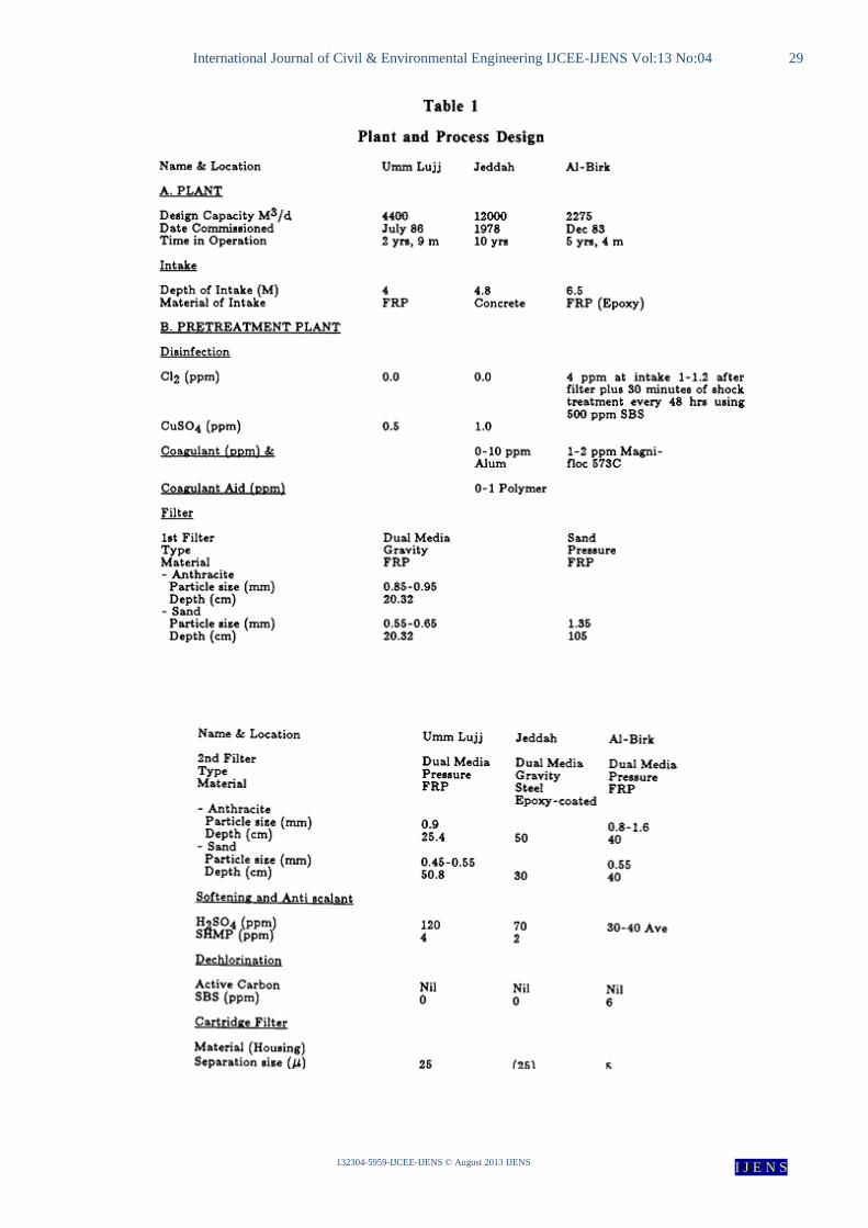
7-2 PLANT COMPARISON
Table 1 is showing the process design data of the
three plants which is including equipment used in these
processes and their material. Table A1 shows the location of
the plants, capacity and date of establishing. Table b,c 1
shows the pretreatment process , and the desalination parts
of the plant. Table d1 shows the post-treatment part of the
plants.
7-3 Pretreatment
7-3-1 Disinfection
As a pretreatment action, and to avoid some of the
seawater problems that may cause damage in some of the
plant’s parts, such as pump, membrane or pipes, we are
attempting to avoid large particles. Some of the TDS which
are present naturally in seawater reduce the plant’s parts
specification or requirements. So the quality of seawater
should be taken into consideration in terms of our plant’s
design (choosing membrane, pipes and pump material)
because seawater may harm these materials; otherwise the
attempt must be made to reduce the seawater content before
feeding the plants.
A- Jeddah plant
UOP thin film and composite (TFC) SW membranes
are used in the Jeddah plant. Water feed is disinfected by a
dose of 1 ppm of the algaecide CuSO4 in the feed (Table
1B). This dosage is less than that in the Al-Birk plants. This
difference gives an indication that the quality of Red Sea
water is of better quality than that of the Gulf Sea where the
Al-Birk plants are located. The sea water that feeds it
contains most algae because Jeddah city is an industrial city.
(Algaecide is a substance used for killing and preventing the
growth of algae).
B- Al-Birk plant
Copper sulfate is an effective algaecide for reducing
or controlling algae and plankton (6). Copper sulfate is used
instead of chlorine to avoid or reduce the risk of damaging
the membrane by chlorine when used as a disinfectant.
However Al-Birk plant utilizes chlorine to disinfect the
water feed to the plant at the concentration of 4 ppm at the
intake, and l-l.2 ppm after the filters.

International Journal of Civil & Environmental Engineering IJCEE-IJENS Vol:13 No:04 26
132304-5959-IJCEE-IJENS © August 2013 IJENS I J E N S
7-3-2 Coagulation - Flocculation - Filtration
7-3-2-1 Coagulation - Flocculation
A- Al-Birk plant
The coagulant Magni-floc 537C is used at the concentration
of l-2 ppm in the water feed at Al-Birk plant .
B- Jeddah plant
Both coagulants: Alum (0-10 ppm) (Chemical
flocculants) and polymer (0-1 ppm) are dosed in the feed of
the Jeddah plant (see Table 1B).
"Alum is used to clarify water by neutralizing
the electrical double layer surrounding very fine
suspended particles, allowing them to flocculate (stick
together)." [3]
7-3-2-2 Filtration
A- Jeddah plants
In the case of filtration systems, a gravity filter with
particle size 0.55 to 0.66 mm which set in order to avoid the
largest partial before reverse osmoses filter, followed by a
pressure dual media filter with fine sand, particle size 0.45 -
0.55 mm, are used in the filtration step before the process of
reverse osmosis in order to avoid larger particles. In addition,
Jeddah plants have a 25 u cartridge filter.
B- Al-Birk plant
Table 1B shows that Al-Birk plant has a
coarse sand filter with particle size 1.35 mm this
may give us an indicator that gulf sea water contain
solid matter bigger than red sea water this can be
easily referred to the narrowest of gulf sea water,
followed by a dual media filter with sand particle
size of 0.55 mm, and has a finer cartridge filter,
size 5 u.
"A cartridge filter is a filter that uses a barrier/sifts
method in order to clean sediments and harmful
solids out of water. Some of these filters are made
to stop microscopic items, and others are made
simply to stop the major solids from entering a
system"[3]
2) 7-4 Post-treatment
3) The same post-treatment actions are used at
the two plants. Table 1D shows a dosage at the
concentration of 30-60 ppm of Ca(OH)2 in order to
stabilize water and alkalinity adjustment
(hardening).
Chlorination is used as a post-treatment action for the
water resulting from reverse osmosis as a final step in order
to avoid and prevent growth of microorganisms during
water distribution to the pipe network or storage.
7-5 Plant Operation & Maintenance (O&M)
Table 3 shows the major operation and maintenance
work done at the two plants. Jeddah and Al-Birk plants are
cleaned three to four times per year.
The cleaning process includes chemical cleaning.
Chemicals used in cleaning the UOP membrane are limited
to three: Citric acid (l%), Borax (l%), and EDTA (1%).
Chemical used in cleaning the membrane at the Al-Birk
plant are: Bis, HCl, Tannic acid, Formaldehyde, Citric acid,
P.O.M.E., etc
CONCLUSION
Reverse osmosis is an important
technique for purifying sea water. Sea water
reverse osmosis desalination plants consist of four
main processes: first, a pretreatment process to
avoid fouling problems and destroying membranes;
second, a pressure pump; third, a membrane
assembly which affects water purification
efficiency; fourth, a disinfection process.
According to the comparison between the two
reverse osmosis plants, whatever processes are
used in reverse osmosis desalination plants, the
quality of purified water is the same but the quality
of the feed water will affect the choice of pre-
treatment, post-treatment and cleaning method.
REFERENCES [1] M. Hassan, and Saleh Al-Jarrah, Thabet Al-Lohabi,
Abdullah Al-Hamdan, and Lutfi M. Bakheet,
Mohamed M.I. Al-Amri, PERFORMANCE EVALUATION OF SWCC SWRO PLANTS, Saline
Water Conversion Corporation Research
Development & Training Center. [2] Ata M. Hassan, A. T .M. Jamaluddin, M. O. Saeed,
Abdullah Al-Rubaian and Ali Al-Reweli, AL-BIRK
SWRO PLANT OPERATION WITH TOYOBO MEMBRANE IN TRAIN 200 INSTEAD OF
DUPONT B-10 MEMBRANE, Saline Water
Conversion Corporation Research Development & Training Center.
[3] Thomas Mani, Abdulrahman Abanmy and Ata M.
Hassan, EFFECT OF ACID DOSING OF SEAWATER FEED AHEAD OF SAND FILTER
ON PHYTOPLANKTON DEGRADATION, Saline
Water Conversion Corporation Research Development & Training Center.
[4] Tzahi Y. Cath Amy E. Childress b, Menachem
Elimelech Forward osmosis: Principles, applications, and recent developments, Division of Environmental
Science and Engineering.
[5] Jian-Jun Qin, Boris Liberman and Kiran A. Kekre, Direct Osmosis for Reverse Osmosis Fouling
Control: Principles, Applications and Recent
Developments, The Centre for Advanced Water Technology, PUB Consultants Pte Ltd.
[6] Sangyoup Lee, Chanhee Boo, Menachem Elimelech, Seungkwan Hong, Comparison of fouling behavior
in forward osmosis (FO) and reverse osmosis (RO),
Journal of Membrane Science. [7] Maria Dina Afonsoa* , Jamal 0. Jaberb, Mousa S .
Mohsen ,Brackish groundwater treatment by reverse
osmosis in Jordan, Chemical Engineering

International Journal of Civil & Environmental Engineering IJCEE-IJENS Vol:13 No:04 27
132304-5959-IJCEE-IJENS © August 2013 IJENS I J E N S
Department, Institute Superior Tecnico,. Desalination
141 (2001) 15-22.
[8] Min Luo, Zhansheng Wang, Complex fouling and
cleaning-in-place of a reverse osmosis desalination
system, Department of Environmental Science and Engineering, Desalination 141 (2001) 15-22.
[9] A. B6dalo-Santoyo, J.L. G6mez-Carrasco, E.
G6mez-G6mez, application of reverse osmosis to reduce pollutants present in industrial wastewater,
Desalination 155 (2003) 101-108.
[10] S.S. Madaeni*, Y. Mansourpanah, Chemical cleaning of reverse osmosis membranes fouled by
whey, Desalination 161 (2004) 13-24.
[11] Ata M. Hassan, REVIEW OF DEVELOPMENT OF THE NEW NF SEAWATER DESALINATION
PROCESS FROM PILOT PLANT TO
COMMERCIAL PRODUCTION PLANT STAGES, Saline Water Conversion Corporation.
[12] A. Mohammed Farooque, Ahamed Al-Amoudi,
A.T.M. Jamaluddin, and Ata M. Hassan, PERFORMANCE RESTORATION, AUTOPSY
AND ANALYSES OF FIVE DIFFERENT
COMMERCIAL SWRO MEMBRANES, Research and Development Center Saline Water Conversion
Cooperation.
[13] Ata M. Hassan, Abdulrahman M. Abanmy, Mohammad Al-Thobiety and Thomas Mani,
PERFORMANCE EVALUATION OF SWCC SWRO PLANTS PART II, SWCC Central
Administration for Satellite Stations, Jeddah.
[14] Abdulgader A. Maghrabi, Troy Green and Shalan Al-Ghamdi, EFFECT OF HIGH FEED
TEMPERATURE ON NANOFILTRATION AND
RO MEMBRANE PERFORMANCE, Saline Water Desalination Research Institute ,Saline Water
Conversion Corporation (SWCC).
[15] Abdul Rahman M. Abanmy, REVERSE OSMOSIS MEMBRANE FOULING - THE FINAL
FRONTIER, Saline Water Conversion Corporation,
Research and Development Center. [16] Khawla AbdulMohsen Al-Shayji, MODELING,
SIMULATION, AND OPTIMIZATION OF
LARGE-SCALE COMMERCIAL DESALINATION PLANTS, Dissertation submitted
to the Faculty of the Virginia Polytechnic Institute
and State University in partial fulfillment of the
requirements for the degree of Doctor of Philosophy
In Chemical Engineering.

International Journal of Civil & Environmental Engineering IJCEE-IJENS Vol:13 No:04 28
132304-5959-IJCEE-IJENS © August 2013 IJENS I J E N S
Appendix
International Journal of Civil & Environmental Engineering IJCEE-IJENS Vol:13 No:04 29
132304-5959-IJCEE-IJENS © August 2013 IJENS I J E N S

International Journal of Civil & Environmental Engineering IJCEE-IJENS Vol:13 No:04 30
132304-5959-IJCEE-IJENS © August 2013 IJENS I J E N S

International Journal of Civil & Environmental Engineering IJCEE-IJENS Vol:13 No:04 31
132304-5959-IJCEE-IJENS © August 2013 IJENS I J E N S