Embed Size (px)
Citation preview

User Guide
Unidrive SPCommander SKCommander SX
Part Number: 0471-0020-08Issue: 8
www.controltechniques.com
SM-CANopen

General InformationThe manufacturer accepts no liability for any consequences resulting from inappropriate, negligent or incorrect installation or adjustment of the optional operating parameters of the equipment or from mismatching the variable speed drive with the motor.
The contents of this guide are believed to be correct at the time of printing. In the interests of a commitment to a policy of continuous development and improvement, Control Techniques reserves the right to change the specification of the product or its performance or the contents of this guide without notice.
All rights reserved. No parts of this guide may be reproduced or transmitted in any form or by any means, electrical or mechanical including photocopying, recording or by an information storage or retrieval system, without permission in writing from the publisher.
Copyright © July 2007 Control Techniques Drives.
Issue Code: 8
Contents1 Safety Information ..........................................................61.1 Warnings, cautions and notes ......................................................................61.2 Electrical safety - general warning ...............................................................61.3 System design and safety of personnel .......................................................61.4 Environmental limits .....................................................................................71.5 Compliance with regulations ........................................................................71.6 Motor ............................................................................................................71.7 Adjusting parameters ...................................................................................7
2 Introduction ....................................................................82.1 What Is CANopen? ......................................................................................82.2 What is SM-CANopen? ..............................................................................102.3 General specification .................................................................................102.4 Solutions Module identification ..................................................................112.5 Product conformance certificate ................................................................112.6 Conventions used in this guide ..................................................................122.7 Conventions used for SM-CANopen ..........................................................12
3 Mechanical Installation ................................................133.1 General Installation ....................................................................................13
4 Electrical Installation ...................................................144.1 SM-CANopen terminal descriptions ...........................................................144.2 SM-CANopen connections .........................................................................154.3 CANopen cable ..........................................................................................154.4 CANopen network termination ...................................................................164.5 SM-CANopen cable shield connections .....................................................164.6 CANopen ground point ..............................................................................174.7 Using the drive as a ground point ..............................................................174.8 Unidrive SP: SM-CANopen back-up power supply ....................................194.9 Maximum network length ...........................................................................204.10 Spurs ..........................................................................................................204.11 Minimum node to node cable length ..........................................................20
SM-CANopen User Guide 3Issue Number: 8 www.controltechniques.com

5 Getting Started .............................................................215.1 SM-CANopen node address ......................................................................225.2 SM-CANopen data rate ..............................................................................225.3 Flexible PDO Numbering (software compatibility) .....................................235.4 PDO number configuration ........................................................................235.5 PDO structure (PDOs A,B,C & D) ..............................................................245.6 Types of set-up ..........................................................................................245.7 Configuration overview ..............................................................................255.8 Setup flowcharts ........................................................................................275.9 SM-CANopen data format ..........................................................................375.10 Default COB-IDs and transmission type ....................................................375.11 SM-CANopen operating status ..................................................................385.12 Resetting the SM-CANopen (re-initialising) ...............................................395.13 Unidrive SP: reset Solutions Modules ........................................................395.14 Storing SM-CANopen configuration parameters ........................................395.15 Restore SM-CANopen defaults ..................................................................405.16 Restore previous SM-CANopen configuration ...........................................41
6 EDS Files .......................................................................436.1 What are EDS files? ...................................................................................436.2 Supplied EDS files .....................................................................................436.3 Changing EDS files/customisation .............................................................44
7 Cyclic Data ....................................................................457.1 What is a “Process Data Object”? ..............................................................457.2 SM-CANopen data format ..........................................................................457.3 Data size on the network ...........................................................................467.4 Default settings ..........................................................................................467.5 PDO data mapping errors ..........................................................................487.6 Unused PDO data channels ......................................................................487.7 Changing PDO mapping parameters .........................................................487.8 Blank mapping parameters ........................................................................49
8 Non-Cyclic Data ............................................................508.1 Service data object (SDO) parameter access ............................................508.2 Mode 1 - CT Single Word mode ................................................................528.3 SM-CANopen set-up using non-cyclic data ...............................................61
9 Control and Status Words ...........................................629.1 What are control and status words? ..........................................................629.2 Control word ...............................................................................................629.3 Status word ................................................................................................64
10 Diagnostics ...................................................................6610.1 Module ID code ..........................................................................................6710.2 SM-CANopen firmware version .................................................................6710.3 SM-CANopen node address ......................................................................6710.4 SM-CANopen data rate ..............................................................................6810.5 SM-CANopen operating status ..................................................................6810.6 SM-CANopen mapping status ...................................................................6910.7 SM-CANopen error code ...........................................................................7210.8 Stuff Bits .....................................................................................................73
4 SM-CANopen User Guidewww.controltechniques.com Issue Number: 8

11 Advanced Features ......................................................7411.1 SM-CANopen network loss trip time-out ....................................................7411.2 SM-CANopen data endian format ..............................................................7511.3 Unidrive SP: inter-option communication timing ........................................7511.4 Local Solutions Module parameter access ................................................7611.5 Unidrive SP: mapping To SM-Applications parameters .............................7611.6 Unidrive SP: block mapping .......................................................................7711.7 Direct data mapping ...................................................................................7911.8 Cyclic data compression ............................................................................8011.9 Unidrive SP: event task trigger in SM-Applications ....................................8011.10 PDOA length ..............................................................................................8111.11 PDO counter .............................................................................................8211.12 Unidrive SP: linking object dictionary entries to DPL program variables ..8211.13 Unidrive SP: SM-Applications object priority ..............................................8411.14 Unidrive SP: synchronised data transfer mode ..........................................8511.15 Unidrive SP: position control without interpolation .....................................9011.16 Unidrive SP: position control with interpolation ..........................................9311.17 Synchronisation example ...........................................................................95
12 CANopen Reference ..................................................10212.1 Communication profile objects supported ................................................10212.2 Basic data types .......................................................................................10212.3 Device type ..............................................................................................10312.4 Flexible PDO numbering (0x2800 and 0x2801) .......................................10912.5 Mapping parameter values ......................................................................11012.6 RxPDO communication parameters ........................................................11312.7 RxPDO mapping parameters ...................................................................11512.8 TxPDO communication parameters .........................................................11712.9 TxPDO mapping parameters ...................................................................12012.10 Network management objects (NMT) ......................................................12312.11 NMT commands .......................................................................................12412.12 Layer setting services (LSS) ....................................................................12512.13 Emergency object ....................................................................................13012.14 Emergency object state ...........................................................................13112.15 Unidrive SP and Commander SK: device profiles ...................................133
13 Quick Reference .........................................................15013.1 Drive menu parameter reference .............................................................15013.2 Virtual parameter reference .....................................................................15113.3 Object reference ......................................................................................152
14 Glossary Of Terms .....................................................153
SM-CANopen User Guide 5Issue Number: 8 www.controltechniques.com

1 Safety Information
1.1 Warnings, cautions and notes
1.2 Electrical safety - general warningThe voltages used in the drive can cause severe electrical shock and/or burns, and could be lethal. Extreme care is necessary at all times when working with or adjacent to the drive.
Specific warnings are given at the relevant places in this User Guide.
1.3 System design and safety of personnelThe drive is intended as a component for professional incorporation into complete equipment or a system. If installed incorrectly, the drive may present a safety hazard.
The drive uses high voltages and currents, carries a high level of stored electrical energy, and is used to control equipment which can cause injury.
Close attention is required to the electrical installation and the system design to avoid hazards either in normal operation or in the event of equipment malfunction. System design, installation, commissioning and maintenance must be carried out by personnel who have the necessary training and experience. They must read this safety information and this User Guide carefully.
The STOP and SECURE DISABLE functions of the drive do not isolate dangerous voltages from the output of the drive or from any external option unit. The supply must be disconnected by an approved electrical isolation device before gaining access to the electrical connections.
With the sole exception of the SECURE DISABLE function, none of the drive functions must be used to ensure safety of personnel, i.e. they must not be used for safety-related functions.
Careful consideration must be given to the functions of the drive which might result in a hazard, either through their intended behaviour or through incorrect operation due to a fault. In any application where a malfunction of the drive or its control system could lead to or allow damage, loss or injury, a risk analysis must be carried out, and where necessary, further measures taken to reduce the risk - for example, an over-speed
A Warning contains information, which is essential for avoiding a safety hazard.
A Caution contains information, which is necessary for avoiding a risk of damage to the product or other equipment.
A Note contains information, which helps to ensure correct operation of the product.
WARNING
CAUTION
NOTE
The SECURE DISABLE function is only available as standard on the Unidrive SP. The Commander SK does not have a secure disable feature. Secure disable is available on Commander SX as an option.
6 SM-CANopen User Guidewww.controltechniques.com Issue Number: 8

Safety Inform
ationIntroduction
Mechanical
InstallationElectrical
InstallationG
etting Started
EDS Files
Cyclic D
ataN
on-Cyclic
Data
Control and
Status Words
Diagnostics
Advanced Features
CAN
open R
eferenceQ
uick R
eferenceG
lossary Of
Terms
Index
protection device in case of failure of the speed control, or a fail-safe mechanical brake in case of loss of motor braking.
The SECURE DISABLE function and secure input on Unidrive SP meet the requirements of EN954-1 category 3 for the prevention of unexpected starting of the drive. They may be used in a safety-related application. The system designer is responsible for ensuring that the complete system is safe and designed correctly according to the relevant safety standards.
1.4 Environmental limitsInstructions in the Unidrive SP User Guide, Commander SK Getting Started Guide, Commander SK Technical Data Guide and Commander SX User Guide regarding transport, storage, installation and use of the drive must be complied with, including the specified environmental limits. Drives must not be subjected to excessive physical force.
1.5 Compliance with regulationsThe installer is responsible for complying with all relevant regulations, such as national wiring regulations, accident prevention regulations and electromagnetic compatibility (EMC) regulations. Particular attention must be given to the cross-sectional areas of conductors, the selection of fuses or other protection, and protective earth (ground) connections.
The Unidrive SP User Guide, Commander SK EMC Guide and Commander SX User Guide contain instructions for achieving compliance with specific EMC standards.
Within the European Union, all machinery in which this product is used must comply with the following directives:
98/37/EC: Safety of machinery.
89/336/EEC: Electromagnetic Compatibility.
1.6 MotorEnsure the motor is installed in accordance with the manufacturer’s recommendations. Ensure the motor shaft is not exposed.
Standard squirrel cage induction motors are designed for single speed operation. If it is intended to use the capability of the drive to run a motor at speeds above its designed maximum, it is strongly recommended that the manufacturer is consulted first.
Low speeds may cause the motor to overheat because the cooling fan becomes less effective. The motor should be fitted with a protection thermistor. If necessary, an electric forced vent fan should be used.
The values of the motor parameters set in the drive affect the protection of the motor. The default values in the drive should not be relied upon.
It is essential that the correct value is entered in the motor rated current parameter: Pr 0.46 for Unidrive SP and Pr 0.06 in Commander SK and Commander SX. This affects the thermal protection of the motor.
1.7 Adjusting parametersSome parameters have a profound effect on the operation of the drive. They must not be altered without careful consideration of the impact on the controlled system. Measures must be taken to prevent unwanted changes due to error or tampering.
SM-CANopen User Guide 7Issue Number: 8 www.controltechniques.com

2 Introduction
2.1 What Is CANopen?CANopen is a networking system that falls into the generic category of fieldbus. Fieldbuses are generally defined as industrial networking systems that are intended to replace traditional wiring systems. Figure 2-1 shows the traditional cabling requirements to transfer signals between 2 slaves and a master.
Figure 2-1 Traditional cable layout
Table 2.1 details how the wiring is used to communicate data between the master and the slaves. Each signal that is communicated requires one signal wire giving a total of 66 signal wires plus a 0V return.
Table 2.1 Traditional wiring details
A fieldbus topology such as CANopen allows the same configuration to be realised using only 2 signal wires plus a screen. This method of communication saves significantly on the amount of cabling required and can improve overall system reliability as the number of interconnections is greatly reduced.
Number of signals
Type Source / Destination Description
16 digital Inputs slave 1 to master status signals16 digital outputs master to slave 1 control signals1 analogue output master to slave 1 control signal 16 digital inputs slave 2 to master status signals16 digital outputs master to slave 2 control signals1 analogue output master to slave 2 control signal
Hardwired master
Slav
e N
umbe
r1
Slave Num
ber2
Analogue 1 Analogue 2
Dig
ital 1
AD
igita
l 1B
Digital 2A
Digital 2B
Digital 1A Digital 1B Digital 2A Digital 2B
Analogue 1 Analogue 2
8 SM-CANopen User Guidewww.controltechniques.com Issue Number: 8

Safety Inform
ationIntroduction
Mechanical
InstallationElectrical
InstallationG
etting Started
EDS Files
Cyclic D
ataN
on-Cyclic
Data
Control and
Status Words
Diagnostics
Advanced Features
CAN
open R
eferenceQ
uick R
eferenceG
lossary Of
Terms
Index
Figure 2-2 shows a typical CANopen network system transferring the same signals as given in the traditionally wired example. The signals are now transmitted by converting them into a serial data stream which is received by the master as if they were connected using traditional wiring. The data stream on CANopen allows up to 32 (16 input and 16 output) independent values to be sent or received by the master, there is also a method available to allow a single channel random access (non-cyclic data access) to drive parameters.
Figure 2-2 CANopen cable layout
Table 2.2 details the number of data words used to communicate the signals using the CANopen network. It can be seen that the resulting reduction in cabling is significant
Table 2.2 Data mappings for SM-CANopen
CANopen transfers data using two distinct modes. The first of these modes is cyclic where signals are sent in predefined blocks at regular intervals. This is the equivalent of the hard-wired example above in Figure 2-1.
Number of network words
Type Source / Destination Description
1 digital Inputs slave 1 to master status signals1 digital outputs master to slave 1 control signals1 analogue output master to slave 1 control signal 1 digital inputs slave 2 to master status signals1 digital outputs master to slave 2 control signals1 analogue output master to slave 2 control signal
CANopen masterDigital 1A Digital 1B Digital 2A Digital 2B
Analogue 1 Analogue 2
Analogue 1 Analogue 2
Digital 2A
Digital 2B
Slave Num
ber2
Slav
e N
umbe
r1
Dig
ital 1
AD
igita
l 1B
SM-CANopen User Guide 9Issue Number: 8 www.controltechniques.com

The second method of transfer is called non-cyclic data (CANopen may use SDOs for non-cyclic data) and is used for sending values that only need to be changed occasionally or where the source or destination of the signal changes. This is the equivalent of a temporary patch lead that is removed after use.
2.2 What is SM-CANopen?SM-CANopen is a fieldbus Solutions Module that can be fitted to the expansion slot(s) in any of the following drives to provide CANopen slave connectivity.
• Unidrive SP• Commander SK• Commander SX (check compatibility status prior to use).
In the case of Unidrive SP it is possible to use more than one SM-CANopen or a combination of SM-CANopen and other Solutions Modules to add additional functionality such as extended I/O, gateway functionality, or additional PLC features.
Figure 2-3 SM-CANopen for Unidrive SP
2.3 General specificationSM-CANopen has been designed to offer as much flexibility as possible, in particular the PDO numbering system has been specifically designed to offer maximum versatility whilst maintaining conformance to CiA specifications.
• Supported data rates (bits/s): 1M, 800K, 500K, 250K, 125K, 100K, 50K, 20K and 10K.
• Four transmit and four receive PDOs (process data objects) supported.• Independently configurable transmit and receive PDO numbers (1-511) for
maximum application flexibility.• All synchronous and asynchronous PDO communication modes supported.• Total of 32 bytes (16 words) in each direction using PDOs (4 TxPDOs of 64
bits and 4 RxPDOs of 64 bits).• Custom handling of specific objects with SM-Applications/SM-Applications
Lite on Unidrive SP.
10 SM-CANopen User Guidewww.controltechniques.com Issue Number: 8

Safety Inform
ationIntroduction
Mechanical
InstallationElectrical
InstallationG
etting Started
EDS Files
Cyclic D
ataN
on-Cyclic
Data
Control and
Status Words
Diagnostics
Advanced Features
CAN
open R
eferenceQ
uick R
eferenceG
lossary Of
Terms
Index
• Direct mapping of PDO data to and from SM-Applications/SM-Applications Lite parameters*.
• Service Data Objects (SDO) provide access to all drive and SM-Applications parameters*.
• Heartbeat protocol supported to guard against loss of communications.• Emergency object supported, with custom user handling on Unidrive SP with
SM-Applications/SM-Applications Lite.• D-type or screw terminal connections for ease of wiring.• Synchronised data transfer, with axis syncronisation on Unidrive SP.• +24V back-up power supply capability via the Unidrive SP.
*Unidrive SP only feature.
2.4 Solutions Module identification The SM-CANopen can be identified by:
1. The label located on the underside of the Solutions Module.2. The colour coding across the front of the SM-CANopen (light grey).
Figure 2-4 SM-CANopen labels
2.4.1 Date code formatThe date code is split into two sections: a letter followed by a number.
The letter indicates the year, and the number indicates the week number (within the year) in which the Solutions Module was built.
The letters are in alphabetical order, starting with A in 1990 (B in 1991, C in 1992 etc.).
Example:A date code of O35 would correspond to week 35 of year 2005.
2.5 Product conformance certificateSM-CANopen has been awarded a CANopen certificate by CAN In Automation (CiA). A copy of the certificate is available from your supplier or local Control Techniques Drive Centre.
SM-CANopen
Revision:0 stdJ41
Ser No : 3000005001
Solutions Module name
Revisionnumber
Customerand date code
Serial number
SM-CANopen User Guide 11Issue Number: 8 www.controltechniques.com

2.6 Conventions used in this guideThe configuration of the host drive and Solutions Module is done using menus and parameters. A menu is a logical collection of parameters that have similar functionality. In the case of a Solutions Module, the parameters will appear in menu 15 for the Commander SK and Commander SX, and in menu 15, 16 or 17 for the Unidrive SP depending on the slot the module is fitted into. The menu is determined by the number before the decimal point. The method used to determine the menu or parameter is as follows:
• Pr xx.00 - signifies any menu and parameter number 00.• Pr MM.xx - where MM signifies the menu allocated to the Solution Module
(this could be 15, 16 or 17 on the Unidrive SP but will always be 15 on the Commander SK and Commander SX) and xx signifies the parameter number.
2.7 Conventions used for SM-CANopenWhen referring to PDOs (process data objects), a PDO normally refers to both TxPDO (transmit process data object) and RxPDO (receive process data object). Where the differences are important this is quantified using the terms TxPDO and RxPDO.
SM-CANopen references PDOs by a letter (A, B,C & D) to differentiate between the configuration of the PDOs and the actual PDO numbers used. SM-CANopen supports 4 TxPDOs (A, B,C & D) and 4 RxPDOs (A, B,C & D) these PDOs have the default PDO numbers of 1, 3, 5 & 6 respectively, however these may be configured to any valid PDO number using a master.
All references in this manual to SM-Applications should also extend to SM-Applications Lite. The exceptions to this are references to SM-Applications input/output, CTSync or the RS485 port, as these are not supported on SM-Applications Lite. For full details of the differences see the Applications Modules User Guide.
NOTE
12 SM-CANopen User Guidewww.controltechniques.com Issue Number: 8

SM-CANopen User Guide 13Issue Number: 8 www.controltechniques.com
Safety Inform
ationIntroduction
Mechanical
InstallationElectrical
InstallationG
etting Started
EDS Files
Cyclic D
ataN
on-Cyclic
Data
Control and
Status Words
Diagnostics
Advanced Features
CAN
open R
eferenceQ
uick R
eferenceG
lossary Of
Terms
Index
3 Mechanical Installation
3.1 General InstallationThe installation of a Solutions Module is illustrated in Figure 3-1.
Figure 3-1 Fitting a Solutions Module
The Solutions Module connector is located on the underside of the module (1). Push this into the Solutions Module slot located on the drive until it clicks into place (2). Note that some drives require a protective tab to be removed from the Solutions Module slot. For further information, refer to the appropriate drive manual.
Before installing or removing a Solutions Module in any drive, ensure the AC supply has been disconnected for at least 10 minutes and refer to Chapter 1 Safety Information on page 6. If using a DC bus supply ensure this is fully discharged before working on any drive or Solutions Module.WARNING
1
2

4 Electrical Installation4.1 SM-CANopen terminal descriptions
SM-CANopen has a standard 5-way screw terminal block connector (shown on the right) for the CANopen network. The 9-way male D-type may also be used to connect to SM-CANopen. These connectors are detailed in the CANopen specification.
Figure 4-1 SM-CANopen - front view
The terminals are numbered from 1-5 reading from left to right (see Figure 4-2).
Table 4.1 SM-CANopen terminal descriptions
5-way terminal
D-type terminal Function Description
1 6 0V 0V CANopen external supply (optional)2 2 CAN-L Negative data line3 3,5 Shell Shield Cable braided shield connection4 7 CAN-H Positive data line5 9 +24V +24V CANopen external supply (optional)
The external supply terminals provide power for the CAN transceiver circuitry, but do NOT provide power to keep SM-CANopen operating in the event of the mains power supply loss to the drive. An external supply will keep the CAN transceivers powered up and the network load characteristics constant in the event of loss of power to the drive.
NOTE
Any external supply must be suitably installed to prevent noise on the network. Pins 1 and 5 are not required by the CANopen network and it is recommended that they are not connected. Connecting pins 1 and 5 to an external supply allows the line driver circuitry to remain powered when the drive and the CANopen module are turned off. This 24V input does not allow SM-CANopen to continue communicating.
CAUTION
14 SM-CANopen User Guidewww.controltechniques.com Issue Number: 8
Safety Inform
ationIntroduction
Mechanical
InstallationElectrical
InstallationG
etting Started
EDS Files
Cyclic D
ataN
on-Cyclic
Data
Control and
Status Words
Diagnostics
Advanced Features
CAN
open R
eferenceQ
uick R
eferenceG
lossary Of
Terms
Index
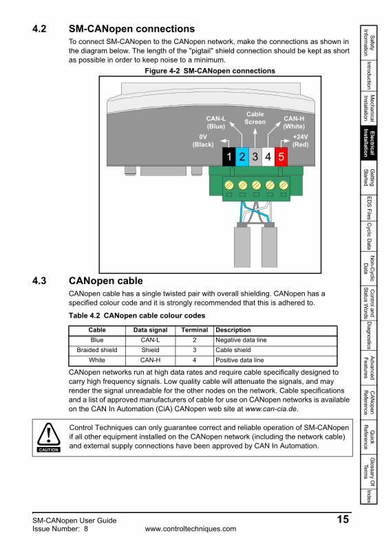
4.2 SM-CANopen connectionsTo connect SM-CANopen to the CANopen network, make the connections as shown in the diagram below. The length of the "pigtail" shield connection should be kept as short as possible in order to keep noise to a minimum.
Figure 4-2 SM-CANopen connections
4.3 CANopen cableCANopen cable has a single twisted pair with overall shielding. CANopen has a specified colour code and it is strongly recommended that this is adhered to.
CANopen networks run at high data rates and require cable specifically designed to carry high frequency signals. Low quality cable will attenuate the signals, and may render the signal unreadable for the other nodes on the network. Cable specifications and a list of approved manufacturers of cable for use on CANopen networks is available on the CAN In Automation (CiA) CANopen web site at www.can-cia.de.
1 2 3 4 5
CAN-L(Blue)
CAN-H(White)
0V(Black)
+24V(Red)
CableScreen
Table 4.2 CANopen cable colour codes
Cable Data signal Terminal DescriptionBlue CAN-L 2 Negative data line
Braided shield Shield 3 Cable shieldWhite CAN-H 4 Positive data line
Control Techniques can only guarantee correct and reliable operation of SM-CANopen if all other equipment installed on the CANopen network (including the network cable) and external supply connections have been approved by CAN In Automation.
CAUTION
SM-CANopen User Guide 15Issue Number: 8 www.controltechniques.com

4.4 CANopen network terminationIt is very important with CANopen that the network communications cable is fitted with the specified termination resistor network at each end of the cable segment. This prevents signals from being reflected back down the cable and causing interference. Termination resistors (120Ω 0.25W) should be fitted across the CAN-H and CAN-L lines at BOTH ends of a network segment, as shown in the diagram below.
Figure 4-3 CANopen network termination
4.5 SM-CANopen cable shield connectionsSM-CANopen should be wired with the cable shields isolated from ground at each drive. The cable shields should be linked together at the point where they emerge from the cable, and formed into a short pigtail to be connected to pin 3 on the CANopen connector as shown in Figure 4-2.
1 2 3 4 5
CAN-L(Blue)
CAN-H(White)
0V(Black)
+24V(Red)
CableScreen
120Ω0.25W
Failure to terminate a network correctly can seriously affect the operation of the network. If the correct termination resistors are not fitted, the noise immunity of the network is greatly reduced. If too many termination resistors are fitted on a CANopen network, the network will be over-loaded, causing reduced signal levels which will result in potential transmission errors.
CAUTION
The CANopen cable can be tie-wrapped to the grounding bar or a local convenient fixing point that is not live to provide strain relief, but the CANopen cable shield must be kept isolated from ground at each node. The only exception to this is the CANopen ground point. Refer to section 4.6 CANopen ground point on page 17.
NOTE
16 SM-CANopen User Guidewww.controltechniques.com Issue Number: 8

Safety Inform
ationIntroduction
Mechanical
InstallationElectrical
InstallationG
etting Started
EDS Files
Cyclic D
ataN
on-Cyclic
Data
Control and
Status Words
Diagnostics
Advanced Features
CAN
open R
eferenceQ
uick R
eferenceG
lossary Of
Terms
Index
4.6 CANopen ground pointThe CANopen ground point is the place on a network segment where the cable screen is grounded for electrical safety.
4.7 Using the drive as a ground point4.7.1 Unidrive SP
When using a Unidrive SP node as the desired ground point, the shield of one of the CANopen cables can be exposed and clamped to the Grounding Bar, as shown in Figure 4-4 below.
Figure 4-4 CANopen ground point on the Unidrive SP
The CANopen cable shield must be grounded AT ONE POINT only, usually near the centre point of the cable run. This is to prevent the cable shield from becoming live in the event of catastrophic failure of another device on the CANopen network. The CANopen ground point is for electrical safety and should not be omitted.CAUTION
Care should be taken when clamping cables to avoid damage to the cable.
3
2
Use a tie-wrap to clamp theCANopen cable to the
A frame
NOTE
SM-CANopen User Guide 17Issue Number: 8 www.controltechniques.com

4.7.2 Commander SKWhen using a Commander SK as the network grounding point it is recommended that the earthing bracket part number 6541-0036-00 is used. The network cable can then be connected to ground using appropriate clamps (not supplied), or alternatively, tied to the bracket using cable ties (see Figure 4-5).
Figure 4-5 SK-Bracket
Care should be taken when clamping cables to avoid damage to the cable.
*
*
NOTE
18 SM-CANopen User Guidewww.controltechniques.com Issue Number: 8

Safety Inform
ationIntroduction
Mechanical
InstallationElectrical
InstallationG
etting Started
EDS Files
Cyclic D
ataN
on-Cyclic
Data
Control and
Status Words
Diagnostics
Advanced Features
CAN
open R
eferenceQ
uick R
eferenceG
lossary Of
Terms
Index
4.7.3 Commander SXWhen using a Commander SX as the network grounding point, connection of the network screen can be performed with suitable glands on the gland plate or by clamping the cable as close to the drive grounding point as possible (see Figure 4-6).
Figure 4-6 Commander SX shield connections
4.8 Unidrive SP: SM-CANopen back-up power supplyIf the CANopen network is required to continue operating in the event of a loss of the mains supply to the Unidrive SP, a back-up +24V power supply should be connected directly to the Unidrive SP. All option modules draw their power from the Unidrive SPs internal power supply and this will ensure that SM-CANopen will continue to communicate in the event of mains supply loss.
Care should be taken when clamping cables to avoid damage to the cable.NOTE
The external power supply pins on the SM-CANopen connectors will NOT keep the SM-CANopen module powered up. These pins only supply power to the CAN transceiver circuitry (with a maximum current drawn of 10mA). The external power supply should be suitably installed so as to prevent external noise entering the drive.
NOTE
SM-CANopen User Guide 19Issue Number: 8 www.controltechniques.com

4.9 Maximum network lengthThe maximum number of nodes that can be connected to a single CANopen network segment is 32. The maximum length of network cable for a CANopen network is dependant on the data rate used (see Table 4.3).
4.10 SpursControl Techniques do not recommend the use of spurs on a CANopen network. For more detailed information please consult the CiA at www.can-cia.org.
4.11 Minimum node to node cable lengthThe CANopen specification does not specify a minimum node to node distance, however, Control Techniques advises a minimum distance of 1m between nodes to prevent excessive mechanical stress and to reduce network reflections.
Table 4.3 CANopen maximum segment lengths
Data rate (bits/sec)
Maximum network length (m)
1M 30800K 50500K 100250K 250125K 500100K 70050K 100020K 250010K 5000
20 SM-CANopen User Guidewww.controltechniques.com Issue Number: 8
Safety Inform
ationIntroduction
Mechanical
InstallationElectrical
InstallationG
etting Started
EDS Files
Cyclic D
ataN
on-Cyclic
Data
Control and
Status Words
Diagnostics
Advanced Features
CAN
open R
eferenceQ
uick R
eferenceG
lossary Of
Terms
Index
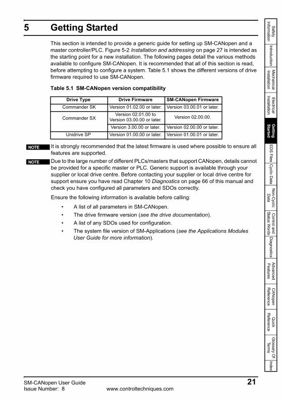
5 Getting StartedThis section is intended to provide a generic guide for setting up SM-CANopen and a master controller/PLC. Figure 5-2 Installation and addressing on page 27 is intended as the starting point for a new installation. The following pages detail the various methods available to configure SM-CANopen. It is recommended that all of this section is read, before attempting to configure a system. Table 5.1 shows the different versions of drive firmware required to use SM-CANopen.
Table 5.1 SM-CANopen version compatibility
Drive Type Drive Firmware SM-CANopen Firmware Commander SK Version 01.02.00 or later. Version 03.00.01 or later.
Commander SX
Version 02.01.00 to Version 03.00.00 or later. Version 02.00.00.
Version 3.00.00 or later. Version 02.00.00 or later.Unidrive SP Version 01.00.00 or later. Version 01.00.01 or later.
It is strongly recommended that the latest firmware is used where possible to ensure all features are supported.Due to the large number of different PLCs/masters that support CANopen, details cannot be provided for a specific master or PLC. Generic support is available through your supplier or local drive centre. Before contacting your supplier or local drive centre for support ensure you have read Chapter 10 Diagnostics on page 66 of this manual and check you have configured all parameters and SDOs correctly.
Ensure the following information is available before calling:
• A list of all parameters in SM-CANopen.• The drive firmware version (see the drive documentation).• A list of any SDOs used for configuration.• The system file version of SM-Applications (see the Applications Modules
User Guide for more information).
NOTE
NOTE
SM-CANopen User Guide 21Issue Number: 8 www.controltechniques.com

5.1 SM-CANopen node address
Every node on a CANopen network must be given a unique network node address. If two or more nodes are assigned the same node address, network errors may result as 2 nodes attempt to transmit at the same time. The valid range for the node address is 0 to 127, with a default address of 0. SM-CANopen must be reset to make a change of node address take effect (see section 5.12 Resetting the SM-CANopen (re-initialising) on page 39).
5.2 SM-CANopen data rate
Every node on a CANopen network must be configured to run at the same network data rate. If a node is configured with the wrong data rate, it may cause errors on the CANopen network and eventually trip on “SLx.Er” (with error code of 66). SM-CANopen must be reset to make a change of data rate take effect (see section 5.12 Resetting the SM-CANopen (re-initialising) on page 39).
5.2.1 Automatic data rate detectionSM-CANopen may be configured to automatically detect the network data rate by setting Pr MM.04 to -1. SM-CANopen will monitor the CANopen network, and if the data rate is detected, it will set Pr MM.04 to the indicate the detected data rate. However, it should be noted that the new value of Pr MM.04 will NOT be stored.The recommended sequence of events using auto-detection of the data rate as follows:1. Power up the drive2. Set Pr MM.04 to -13. Reset SM-CANopen by setting Pr MM.32 to ON.4. Connect SM-CANopen to the CANopen network.5. Wait for Pr MM.04 to change from -1.
SM-CANopen node address
Pr MM.03Default 0Range 0 to 127Access RW
If an invalid node address is set, SM-CANopen will over-write the value in Pr MM.03 with 0. When SM-CANopen is reset, this value will be used as the node address. A node address of 0 will disable the CANopen communications layer but the DSP305 V1.1 Layer Setting Service (LSS) will still be active. Refer to section 12.10 Network management objects (NMT) on page 123 for further details.
NOTE
SM-CANopen data rate
Pr MM.04Default 2 (500kb/s)Range -1 to 8Access RW
Table 5.2 SM-CANopen data rates
Pr MM.04 bits/s Pr MM.04 bits/s-1 Auto 4 125K0 1.0M 5 100K1 800K 6 50K2 500K 7 20K3 250K 8 10K
22 SM-CANopen User Guidewww.controltechniques.com Issue Number: 8

Safety Inform
ationIntroduction
Mechanical
InstallationElectrical
InstallationG
etting Started
EDS Files
Cyclic D
ataN
on-Cyclic
Data
Control and
Status Words
Diagnostics
Advanced Features
CAN
open R
eferenceQ
uick R
eferenceG
lossary Of
Terms
Index
6. Store the Unidrive SP/Commander SK parameters by setting Pr MM.00 to 1000 and pressing RESET. For the Commander SX store the parameters by pressing the M key.
5.3 Flexible PDO Numbering (software compatibility)Different software versions handle PDO configuration with varying degrees of flexibility, as detailed below.
5.3.1 Software versions prior to V02.01.00The PDO numbering scheme is fixed and cannot be changed. The PDOs available are TxPDOs 1,3,5 & 6 and RxPDOs 1,3,5 & 6.
5.3.2 Software version 02.01.00PDO1 is fixed and cannot be changed. To configure up to 3 additional PDOs all that is required is to set up the PDO using SDOs at network start-up. This is the same procedure as for previous firmware releases using PDOs 3, 5 and 6 but uses the object number for the new PDO during set-up (i.e. base address + PDO number -1). A maximum of 4 PDOs are allowed and all, apart from PDO1 may be set up to any PDO in the range 0x002-0x1FF. TxPDO and RxPDO numbering is independent. If additional PDOs are mapped an error message will be produced as only the first 3 additional mappings will be accepted by SM-CANopen. To summarise, the first 3 additional PDOs that are configured will be added to SM-CANopen giving a total of 4 PDOs in each direction.
5.3.3 Software versions 03.01.01 and laterThe default pre-defined PDO numbers for both TxPDOs and RxPDOs remain as 1,3,5 and 6. However, new objects 0x2800 and 0x2801 have been added to allow both TxPDOs and RxPDOs to be re-numbered. This allows 4 PDOs to be configured in each direction, these are referred to as PDOs A,B,C & D as the actual numbers may be changed. Any changes to PDO numbering can only be achieved using objects 0x2800 and 0x2801.
5.4 PDO number configurationIf a master dictates the changing of a PDO number for a specific sub-index in object 0x2800 or 0x2801, doing this will result in the existing PDO configuration objects being destroyed and objects for the new PDO being created with default values, and will take effect immediately. If the PDO number is already used within the same object the old PDO will be overwritten. It is now possible to have different numbers for individual TxPDOs and RxPDOs eg. TxPDO 1,2,3,4 and RxPDO 5,6,7,8.
5.4.1 Object 0x2800 (RxPDO number configuration)Sub Index 0 : Will return 4 when read indicating the maximum sub-index and number of PDOs supported.
Sub Index 1 – 4 : Are used to read and set the RxPDO number for each of the 4 configurable RxPDOs. The number is specified as the required number less 1. That is, PDO1 would be represented as 0.
SM-CANopen will not be able to reliably detect the network data rate if there is little or no traffic on the network. Auto detection of the data rate is ideal when connecting a new node to an existing network, but may not work reliably if a network is powered up with all nodes attempting to detect the data rate.
NOTE
SM-CANopen User Guide 23Issue Number: 8 www.controltechniques.com

5.4.2 Object 0x2801 (TxPDO number configuration)Sub Index 0 : Will return 4 when read indicating the maximum sub-index and number of PDOs supported.
Sub Index 1 – 4 : Are used to read and set the TxPDO number for each of the 4 configurable TxPDOs. The actual index number is calculated by subtracting 1 from the PDO number and adding this number to the base address e.g. for 0x1600 PDO3 = 0x1602.
5.5 PDO structure (PDOs A,B,C & D)SM-CANopen provides 4 TxPDOs and 4 RxPDOs these are referred to as PDOs A,B,C & D, by default these are configured as PDOs 1,3,5 & 6 respectively. PDOA (by default PDO1) may be configured entirely from the Pr MM.xx (SM-CANopen) parameters without the need for a master. The remaining PDOs (B,C & D) which by default are allocated to PDOs 3,5 & 6 respectively, require a master to configure them using SDOs (PDOA may also be configured with a master). The benefits of using this scheme are that it allows the 4 PDOs (A,B,C,D) to be configured to any valid PDO number required whilst still achieving conformance.
5.6 Types of set-upSM-CANopen offers several different methods of configuration that depend on the number of PDOs required and the type of master involved.
5.6.1 Configuration by SM-CANopen parameters only (no master, single PDO)A single PDO (PDOA) may be configured by using the Pr MM.xx (SM-CANopen) parameters alone. The default setting for the first PDO (PDOA) is TxPDO 1 and RxPDO1. All settings such as transmission type, TxPDO length, RxPDO length, TxPDO mappings and RxPDO mappings can be configured directly from the menu associated with SM-CANopen. This allows simple configuration, but is restricted to a single PDO.
5.6.2 Configuration using the pre-configured PDOs by SDO (master required)The default SM-CANopen configuration supports PDOs A,B,C & D set to PDOs 1,3,5 & 6 respectively. In order to use all of these PDOs the configuration of the PDOs must be performed by the master (using SDOs) when the network starts.
5.6.3 Flexible PDO numbering (master required)SM-CANopen provides a special method of reconfiguring the available PDOs while still maintaining conformance (objects 0x2800 and 0x2801). This method allows 4 TxPDOs (A,B,C & D) and 4 RxPDOs (A,B,C & D) to be configured individually to any valid PDO number. It is not necessary for the TxPDOs and RxPDOs to have the same PDO numbers, thus allowing for absolute flexibility during configuration. The configuration objects for the configured PDOs are taken from the base address of the object (eg. 0x1800) plus the configured PDO number minus 1 (e.g. PDO2 would use 0x1801).
The default transmission type, asynchronous timer trigger (type 255) for TxPDOA cannot be configured without a master, as the SM-CANopen internal timer must be configured to use this feature. For use without a master the transmission type should be changed. This default configuration prevents a partially configured node from transmitting on the network.
NOTE
24 SM-CANopen User Guidewww.controltechniques.com Issue Number: 8

Safety Inform
ationIntroduction
Mechanical
InstallationElectrical
InstallationG
etting Started
EDS Files
Cyclic D
ataN
on-Cyclic
Data
Control and
Status Words
Diagnostics
Advanced Features
CAN
open R
eferenceQ
uick R
eferenceG
lossary Of
Terms
Index
5.6.4 SDO savingA method for saving the configured PDOs is available by using a special object (0x1010), which allows all communication settings to be stored in SM-CANopen. This allows SM-CANopen to retain the settings sent by the configuration SDOs from the master. The node is then able to resume communications without requiring the SDO configuration to be re-sent by the master, following a reset or loss of power. This procedure does not replace a drive parameter save.
5.6.5 Pre-configuration for a machine (master required initially)The SDO saving option (0x1010) allows SM-CANopen to be pre-configured on a master before use on a system. This allows the product to be configured for use with a master that does not support SDO configuration of the slave device, or a master that requires a specific set of PDO numbers. This effectively allows the module to be pre-configured before installation and allows SM-CANopen to work in existing hardware configurations with different PDO numbering schemes.
5.7 Configuration overviewFigure 5-1 PDO Configuration overview on page 26 gives an overview of the configuration process required for SM-CANopen communication objects, details are given for the key stages of set-up. In particular the stages involved in configuring PDO numbers (if required) and the required set-up parameters and objects are shown. Additional details of the objects can be found in the sections relating to the specific objects. It is recommended that all of this section is read before configuring SM-CANopen. This overview is supplemented by the set-up flowcharts that follow.
If an SDO overwrites the settings made in Pr MM.xx (SM-CANopen) then the values for the communications objects will be changed, however the values stored in the parameters will not be altered. To indicate that SDOs have changed the configuration of SM-CANopen, Pr MM.05 will show a value of 300.
NOTE
For SM-CANopen firmware 03.01.00 and above, any modifications to the standard configuration for PDOA performed over the SDO protocol will result in the mode parameter (Pr MM.05) being set to 300.
NOTE
SM-CANopen User Guide 25Issue Number: 8 www.controltechniques.com
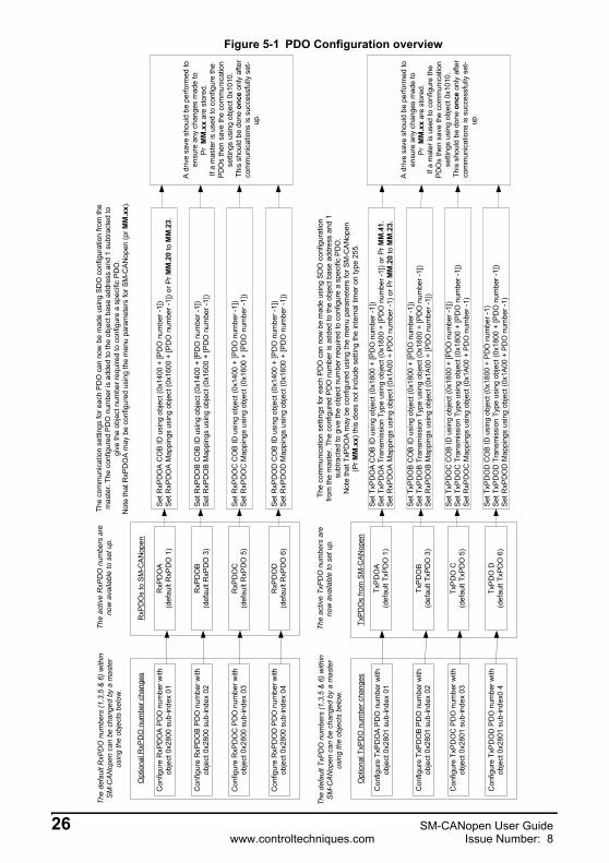
Figure 5-1 PDO Configuration overview
Set R
xPD
OA
CO
B ID
usi
ng o
bjec
t (0x
1400
+ [P
DO
num
ber -
1])
Set R
xPD
OA
Map
ping
s us
ing
obje
ct (0
x160
0 +
[PD
O n
umbe
r -1]
) or P
r MM
.20
to M
M.2
3.
Set R
xPD
OB
CO
B ID
usi
ng o
bjec
t (0x
1400
+ [P
DO
num
ber -
1])
Set R
xPD
OB
Map
ping
s us
ing
obje
ct (0
x160
0 +
[PD
O n
umbe
r -1]
)
Set R
xPD
OC
CO
B ID
usi
ng o
bjec
t (0x
1400
+ [P
DO
num
ber -
1])
Set R
xPD
OC
Map
ping
s us
ing
obje
ct (0
x160
0 +
[PD
O n
umbe
r -1]
)
Set R
xPD
OD
CO
B ID
usi
ng o
bjec
t (0x
1400
+ [P
DO
num
ber -
1])
Set R
xPD
OD
Map
ping
s us
ing
obje
ct (0
x160
0 +
[PD
O n
umbe
r -1]
)
Set T
xPD
OA
CO
B ID
usi
ng o
bjec
t (0x
1800
+ [P
DO
num
ber -
1])
Set T
xPD
OA
Tra
nsm
issi
on T
ype
usin
g ob
ject
(0x1
800
+ [P
DO
num
ber -
1]) o
r Pr M
M.4
1.Se
t RxP
DO
A M
appi
ngs
usin
g ob
ject
(0x1
A00
+ P
DO
num
ber -
1) o
r Pr M
M.2
0 to
MM
.23.
Set T
xPD
OB
CO
B ID
usi
ng o
bjec
t (0x
1800
+ [P
DO
num
ber -
1])
Set T
xPD
OB
Tra
nsm
issi
on T
ype
usin
g ob
ject
(0x1
800
+ [P
DO
num
ber -
1])
Set R
xPD
OB
Map
ping
s us
ing
obje
ct (0
x1A
00 +
[PD
O n
umbe
r -1]
)
Set T
xPD
OC
CO
B ID
usi
ng o
bjec
t (0x
1800
+ [P
DO
num
ber -
1])
Set T
xPD
OC
Tra
nsm
issi
on T
ype
usin
g ob
ject
(0x1
800
+ [P
DO
num
ber -
1])
Set R
xPD
OC
Map
ping
s us
ing
obje
ct (0
x1A0
0 +
PDO
num
ber -
1)
Set T
xPD
OD
CO
B ID
usi
ng o
bjec
t (0x
1800
+ P
DO
num
ber -
1)Se
t TxP
DO
D T
rans
mis
sion
Typ
e us
ing
obje
ct (0
x180
0 +
[PD
O n
umbe
r -1]
)Se
t RxP
DO
D M
appi
ngs
usin
g ob
ject
(0x1
A00
+ PD
O n
umbe
r -1)
RxP
DO
s to
SM
-CA
Nop
en
TxP
DO
s fro
m S
M-C
ANop
en
RxP
DO
A(d
efau
lt R
xPD
O 1
)
RxP
DO
B(d
efau
lt R
xPD
O 3
)
RxP
DO
C(d
efau
lt R
xPD
O 5
)
RxP
DO
D(d
efau
lt R
xPD
O 6
)
TxPD
OA
(def
ault
TxPD
O 1
)
TxPD
OB
(def
ault
TxPD
O 3
)
TxPD
O C
(def
ault
TxPD
O 5
)
TxPD
O D
(def
ault
TxPD
O 6
)
Con
figur
e R
xPD
OA
PD
O n
umbe
r with
obje
ct 0
x280
0 su
b-in
dex
01
Con
figur
e R
xPD
OB
PD
O n
umbe
r with
obje
ct 0
x280
0 su
b-in
dex
02
Con
figur
e R
xPD
OC
PD
O n
umbe
r with
obje
ct 0
x280
0 su
b-in
dex
03
Con
figur
e R
xPD
OD
PD
O n
umbe
r with
obje
ct 0
x280
0 su
b-in
dex
04
Con
figur
e Tx
PD
OA
PD
O n
umbe
r with
obje
ct 0
x280
1 su
b-in
dex
01
Con
figur
e Tx
PD
OB
PD
O n
umbe
r with
obje
ct 0
x280
1 su
b-in
dex
02
Con
figur
e Tx
PDO
C P
DO
num
ber w
ithob
ject
0x2
801
sub-
inde
x 03
Con
figur
e Tx
PDO
D P
DO
num
ber w
ithob
ject
0x2
801
sub-
inde
x0 4
Opt
iona
l RxP
DO
num
ber c
hang
es
Opt
iona
l TxP
DO
num
ber c
hang
es
The
defa
ult R
xPD
O n
umbe
rs (1
,3,5
& 6
) with
inSM
-CAN
open
can
be
chan
ged
by a
mas
ter
usin
g th
e ob
ject
s be
low
.
The
defa
ult T
xPD
O n
umbe
rs (1
,3,5
& 6
) with
inSM
-CAN
open
can
be
chan
ged
by a
mas
ter
usin
g th
e ob
ject
s be
low
.
The
activ
e R
xPD
O n
umbe
rs a
reno
w a
vaila
ble
to s
et u
p.
The
activ
e Tx
PD
O n
umbe
rs a
reno
w a
vaila
ble
to s
et u
p.
The
com
mun
icat
ion
setti
ngs
for e
ach
PDO
can
now
be
mad
e us
ing
SDO
con
figur
atio
n fro
m th
em
aste
r. Th
e co
nfig
ured
PD
O n
umbe
r is
adde
d to
the
obje
ct b
ase
addr
ess
and
1 su
btra
cted
togi
ve th
e ob
ject
num
ber r
equi
red
to c
onfig
ure
a sp
ecifi
c P
DO
.N
ote
that
RxP
DO
A m
ay b
e co
nfig
ured
usi
ng th
e m
enu
para
met
ers
for S
M-C
ANop
en (p
r MM
.xx)
.
The
com
mun
icat
ion
setti
ngs
for e
ach
PD
O c
an n
ow b
e m
ade
usin
g S
DO
con
figur
atio
nfro
m th
e m
aste
r. Th
e co
nfig
ured
PD
O n
umbe
r is
adde
d to
the
obje
ct b
ase
addr
ess
and
1su
btra
cted
to g
ive
the
obje
ct n
umbe
r req
uire
d to
con
figur
e a
spec
ific
PD
O.
Not
e th
at T
xPD
OA
may
be
conf
igur
ed u
sing
the
men
u pa
ram
eter
s fo
r SM
-CA
Nop
en(P
r MM
.xx)
this
doe
s no
t inc
lude
set
ting
the
inte
rnal
tim
er o
n ty
pe 2
55.
A dr
ive
save
sho
uld
be p
erfo
rmed
toen
sure
any
cha
nges
mad
e to
Pr M
M.x
x ar
e st
ored
.If
a m
aste
r is
used
to c
onfig
ure
the
PDO
s th
en s
ave
the
com
mun
icat
ion
setti
ngs
usin
g ob
ject
0x1
010.
Thi
s sh
ould
be
done
onc
e on
ly a
fter
com
mun
icat
ions
is s
ucce
ssfu
lly s
et-
up.
A dr
ive
save
sho
uld
be p
erfo
rmed
toen
sure
any
cha
nges
mad
e to
Pr M
M.x
x ar
e st
ored
.If
a m
ater
is u
sed
to c
onfig
ure
the
PDO
s th
en s
ave
the
com
mun
icat
ion
setti
ngs
usin
g ob
ject
0x1
010.
Thi
s sh
ould
be
done
onc
e on
ly a
fter
com
mun
icat
ions
is s
ucce
ssfu
lly s
et-
up.
26 SM-CANopen User Guidewww.controltechniques.com Issue Number: 8
Safety Inform
ationIntroduction
Mechanical
InstallationElectrical
InstallationG
etting Started
EDS Files
Cyclic D
ataN
on-Cyclic
Data
Control and
Status Words
Diagnostics
Advanced Features
CAN
open R
eferenceQ
uick R
eferenceG
lossary Of
Terms
Index
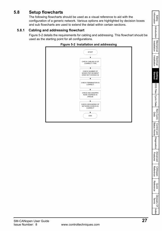
5.8 Setup flowchartsThe following flowcharts should be used as a visual reference to aid with the configuration of a generic network. Various options are highlighted by decision boxes and sub flowcharts are used to extend the detail within certain sections.
5.8.1 Cabling and addressing flowchartFigure 5-2 details the requirements for cabling and addressing. This flowchart should be used as the starting point for all configurations.
Figure 5-2 Installation and addressing
START
CHECK CABLING IS OFCORRECT TYPE
CHECK NUMBER OFNODES PER SEGMENTDOES NOT EXCEED 32
CHECK TERMINATION ISCORRECT
CHECK GROUNDING OFNETWORK SCREEN IS
CORRECT
END
CHECK SM-CANOPENNODE ADDRESS IS
UNIQUE
SM-CANopen User Guide 27Issue Number: 8 www.controltechniques.com

5.8.2 Configuring SM-CANopenFigure 5-3 details the main setup procedure for the PDO settings on SM-CANopen. To break the procedure into manageable sections, additional sub flowcharts are referred to that expand the detail where necessary (always return to this flowchart after completion of a sub flowchart).
Figure 5-3 Configuration Options Flowchart
START
USING DEFAULTCONFIGURATION?
CONFIGURING DRIVEWITH MASTER?
RESET MODULE(Pr MM.32 = 1)
PERFORM DRIVE SAVEXX.00 = 1000 + RESET
BUTTON ON DRIVE(FOR COMMANDER SX
PRESS M KEY)
(FOR UNIDRIVE SP USE 1001 IF ON 24V SUPPLY ONLY)
NOYES
YESNO
Non default configuration is as follows:Allows 4 TxPDOs (1-511) and 4 RxPDOs(1-511). TxPDO and RxPDO numbers canbe different.
Flexible PDO numbering
RxPDO & TxPDO numbers1, 3, 5 and 6
Single RxPDO1 &TxPDO1
Default configuration is as follows:TxPDO1, 3, 5, 6 and RxPDO1, 3, 5 and 6.Or single PDO1 configured by slotparameters (Pr MM.xx).
FLEXIBLE PDONUMBERING
CONFIGURATION(Figure 5-10)
MAPPINGSCONFIGURATION(Figure 5-6 to 5-9)
MAPPINGSCONFIGURATION(Figure 5-6 to 5-9)
DEFAULT PDONUMBERING
CONFIGURATION(Figure 5-5)
SINGLE PDO usingPr MM.xx
CONFIGURATION(Figure 5-4)
END
= SUBFLOWCHART
KEY
SAVECONFIGURATION
(Figure 5-11)
SAVECONFIGURATION
(Figure 5-11)
Default configurationRxPDO1 and TxPDO1
A master is required for thisconfiguration
A master is required for thisconfiguration
28 SM-CANopen User Guidewww.controltechniques.com Issue Number: 8

Safety Inform
ationIntroduction
Mechanical
InstallationElectrical
InstallationG
etting Started
EDS Files
Cyclic D
ataN
on-Cyclic
Data
Control and
Status Words
Diagnostics
Advanced Features
CAN
open R
eferenceQ
uick R
eferenceG
lossary Of
Terms
Index
5.8.3 Single PDO configuration using drive parametersFigure 5-4 details the steps required to configure SM-CANopen for a single PDO (PDOA which by default is 1) using only the drive menus. This means for a single PDO1 SM-CANopen does not require a master to configure PDO1. The default PDOs in the module are RxPDO 1, 3, 5 and 6.
Figure 5-4 Manual Configuration Flowchart
This chart is used in conjunction with Figure 5-3 Configuration Options Flowchart on page 28.
Return to Figure 5-3 Configuration Options Flowchart on page 28
Set Pr MM.39TxPDO LENGTH
Set Pr MM.40RxPDO LENGTH
Set Pr MM.41TxPDO TYPE
16 OR 32 BITPARAMETERS?
MAPPED PARAMETERSMAY BE ANY SIZE
MAPPED PARAMETERSMUST BE 16 BITS OR
LESS
SET MAPPINGSPr MM.10 - Pr MM.11
TxPDO *
Set Pr MM.34 = 1 (ON)
SET MAPPINGSPr MM.20 - Pr MM.21
RxPDO *
SET MAPPINGSPr MM.10 - Pr MM.13
TxPDO *
SET MAPPINGSPr MM.20 - Pr MM.23
RxPDO *
TxPDOA AND RxPDOA ARE BOTHCONFIGURED AS 1 BY DEFAULT,BUT IT MAY BE CHANGED USING
SDO CONFIGURATION SEEFIGURE 5-10
NUMBER OF MAPPINGS:2 * 32 MAPPINGS IN2 * 32 MAPPINGS OUT
NUMBER OF MAPPINGS:4 * 16 BIT MAPPINGS IN4 * 16 BIT MAPPINGS OUT
START
END* By entering parameter numbers in integerformat e.g. Pr 18.11 would be entered as
1811.
NOTE
SM-CANopen User Guide 29Issue Number: 8 www.controltechniques.com

5.8.4 Configuration of default PDOsFigure 5-5 details the SDOs required to setup the default RxPDOs and TxPDOs contained within the module. The default PDOs in the module are RxPDOs 1, 3, 5 and 6 and TxPDOs 1, 3, 5 and 6.
Figure 5-5 Sub flowchart for default PDO numbering
This chart is used in conjunction with Figure 5-3 Configuration Options Flowchart on page 28.
SET COB-ID TxPDO1(0x1800) SUB-INDEX 1
SET TRANSMISSION TYPETxPDO1
(0x1800) SUB-INDEX 2
SET COB-ID RxPDO6(0x1405) SUB-INDEX 1
SET COB-ID RxPDO3(0x1402) SUB-INDEX 1
SET COB-ID RxPDO1(0x1400) SUB-INDEX 1
SET COB-ID TxPDO6(0x1805) SUB-INDEX 1
SET COB-ID TxPDO5(0x1804) SUB-INDEX 1
SET COB-ID TxPDO3(0x1802) SUB-INDEX 1
SET COB-ID RxPDO5(0x1404) SUB-INDEX 1
SET TRANSMISSION TYPETxPDO3
(0x1802) SUB-INDEX 2
SET TRANSMISSION TYPERxPDO5
(0x1404) SUB-INDEX 2
SET TRANSMISSION TYPERxPDO3
(0x1402) SUB-INDEX 2
SET TRANSMISSION TYPERxPDO1
(0x1400) SUB-INDEX 2
SET TRANSMISSION TYPETxPDO6
(0x1805) SUB-INDEX 2
SET TRANSMISSION TYPETxPDO5
(0x1804) SUB-INDEX 2
SET TRANSMISSION TYPERxPDO6
(0x1405) SUB-INDEX 2
START
END
NOTE
30 SM-CANopen User Guidewww.controltechniques.com Issue Number: 8
Safety Inform
ationIntroduction
Mechanical
InstallationElectrical
InstallationG
etting Started
EDS Files
Cyclic D
ataN
on-Cyclic
Data
Control and
Status Words
Diagnostics
Advanced Features
CAN
open R
eferenceQ
uick R
eferenceG
lossary Of
Terms
Index
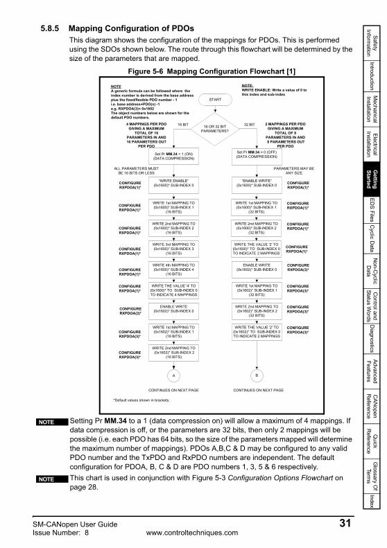
5.8.5 Mapping Configuration of PDOsThis diagram shows the configuration of the mappings for PDOs. This is performed using the SDOs shown below. The route through this flowchart will be determined by the size of the parameters that are mapped.
Figure 5-6 Mapping Configuration Flowchart [1]
Setting Pr MM.34 to a 1 (data compression on) will allow a maximum of 4 mappings. If data compression is off, or the parameters are 32 bits, then only 2 mappings will be possible (i.e. each PDO has 64 bits, so the size of the parameters mapped will determine the maximum number of mappings). PDOs A,B,C & D may be configured to any valid PDO number and the TxPDO and RxPDO numbers are independent. The default configuration for PDOA, B, C & D are PDO numbers 1, 3, 5 & 6 respectively.This chart is used in conjunction with Figure 5-3 Configuration Options Flowchart on page 28.
4 MAPPINGS PER PDOGIVING A MAXIMUM
TOTAL OF 16PARAMETERS IN AND16 PARAMETERS OUT
PER PDO
Set Pr MM.34 = 1 (ON)(DATA COMPRESSION)
Set Pr MM.34 = 0 (OFF)(DATA COMPRESSION)
“WRITE ENABLE”(0x1600)* SUB-INDEX 0
“ENABLE WRITE”(0x1600)* SUB-INDEX 0
2 MAPPINGS PER PDOGIVING A MAXIMUM
TOTAL OF 8PARAMETERS IN AND 8 PARAMETERS OUT
PER PDO
CONFIGURERXPDOA(1)*
CONFIGURERXPDOA(1)*
NOTEA generic formula can be followed where theindex number is derived from the base addressplus the fixed/flexible PDO number - 1i.e. base address+PDO(n) -1e.g. RXPDOA(3)= 0x1602The object numbers below are shown for thedefault PDO numbers.
CONFIGURERXPDOA(3)*
WRITE 1st MAPPING TO(0x1600)* SUB-INDEX 1
(16 BITS)
WRITE 2nd MAPPING TO(0x1600)* SUB-INDEX 2
(16 BITS)
WRITE 3rd MAPPING TO(0x1600)* SUB-INDEX 3
(16 BITS)
WRITE 4th MAPPING TO(0x1600)* SUB-INDEX 4
(16 BITS)
WRITE THE VALUE '4' TO(0x1600)* TO SUB-INDEX 0TO INDICATE 4 MAPPINGS
ENABLE WRITE(0x1602)* SUB-INDEX 0
WRITE 1st MAPPING TO(0x1602)* SUB-INDEX 1
(16 BITS)
WRITE 2nd MAPPING TO (0x1602)* SUB-INDEX 2
(16 BITS)
CONFIGURERXPDOA(3)*
WRITE 1st MAPPING TO(0x1600)* SUB-INDEX 1
(32 BITS)
WRITE 2nd MAPPING TO(0x1600)* SUB-INDEX 2
(32 BITS)
WRITE THE VALUE '2' TO(0x1600)* TO SUB-INDEX 0TO INDICATE 2 MAPPINGS
ENABLE WRITE(0x1602)* SUB-INDEX 0
WRITE 1st MAPPING TO (0x1602)* SUB-INDEX 1
(32 BITS)
WRITE 2nd MAPPING TO (0x1602)* SUB-INDEX 2
(32 BITS)
WRITE THE VALUE '2' TO(0x1602)* TO SUB-INDEX 0TO INDICATE 2 MAPPINGS
ALL PARAMETERS MUSTBE 16 BITS OR LESS
PARAMETERS MAY BEANY SIZE
16 OR 32 BITPARAMETERS?
16 BIT 32 BIT
START
A B
CONTINUES ON NEXT PAGE CONTINUES ON NEXT PAGE
*Default values shown in brackets.
CONFIGURERXPDOA(1)*
CONFIGURERXPDOA(1)*
CONFIGURERXPDOA(1)*
CONFIGURERXPDOA(1)*
CONFIGURERXPDOA(1)*
CONFIGURERXPDOA(1)*
CONFIGURERXPDOA(1)*
CONFIGURERXPDOA(1)*
CONFIGURERXPDOA(3)*
CONFIGURERXPDOA(3)*
CONFIGURERXPDOA(3)*CONFIGURE
RXPDOA(3)*
CONFIGURERXPDOA(3)*
NOTE:WRITE ENABLE: Write a value of 0 tothis index and sub-index
NOTE
NOTE
SM-CANopen User Guide 31Issue Number: 8 www.controltechniques.com
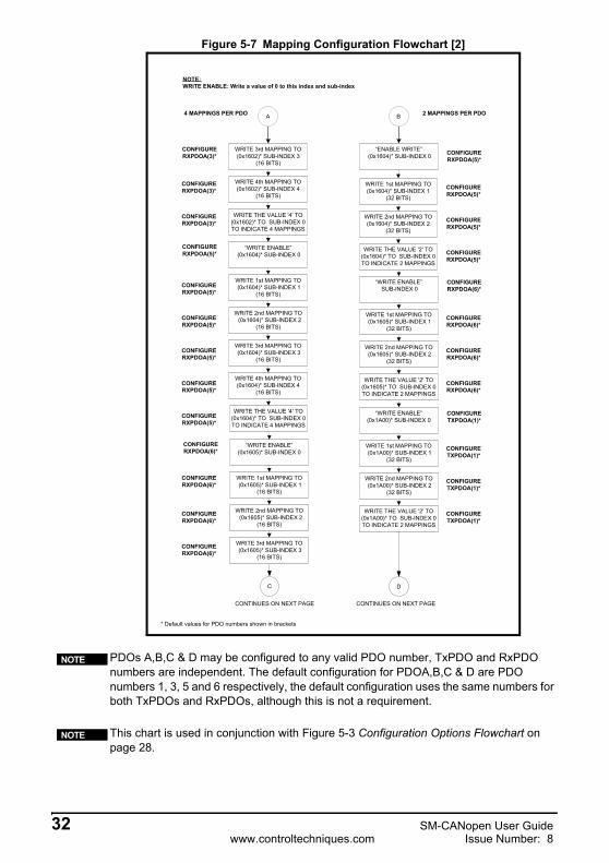
Figure 5-7 Mapping Configuration Flowchart [2]
PDOs A,B,C & D may be configured to any valid PDO number, TxPDO and RxPDO numbers are independent. The default configuration for PDOA,B,C & D are PDO numbers 1, 3, 5 and 6 respectively, the default configuration uses the same numbers for both TxPDOs and RxPDOs, although this is not a requirement.
This chart is used in conjunction with Figure 5-3 Configuration Options Flowchart on page 28.
4 MAPPINGS PER PDO
“ENABLE WRITE” (0x1604)* SUB-INDEX 0
C
2 MAPPINGS PER PDO
CONFIGURERXPDOA(3)* CONFIGURE
RXPDOA(5)*
CONFIGURERXPDOA(5)*
WRITE 3rd MAPPING TO(0x1602)* SUB-INDEX 3
(16 BITS)
WRITE 4th MAPPING TO(0x1602)* SUB-INDEX 4
(16 BITS)
WRITE THE VALUE '4' TO(0x1602)* TO SUB-INDEX 0TO INDICATE 4 MAPPINGS
“WRITE ENABLE” (0x1604)* SUB-INDEX 0
WRITE 1st MAPPING TO (0x1604)* SUB-INDEX 1
(16 BITS)
WRITE 2nd MAPPING TO (0x1604)* SUB-INDEX 2
(16 BITS)
CONFIGURERXPDOA(6)*
WRITE 1st MAPPING TO(0x1604)* SUB-INDEX 1
(32 BITS)
WRITE 2nd MAPPING TO(0x1604)* SUB-INDEX 2
(32 BITS)
WRITE THE VALUE '2' TO(0x1604)* TO SUB-INDEX 0TO INDICATE 2 MAPPINGS
“WRITE ENABLE” SUB-INDEX 0
WRITE 1st MAPPING TO (0x1605)* SUB-INDEX 1
(32 BITS)
WRITE 2nd MAPPING TO (0x1605)* SUB-INDEX 2
(32 BITS)
WRITE THE VALUE '2' TO(0x1605)* TO SUB-INDEX 0TO INDICATE 2 MAPPINGS
WRITE 3rd MAPPING TO (0x1604)* SUB-INDEX 3
(16 BITS)
WRITE 4th MAPPING TO(0x1604)* SUB-INDEX 4
(16 BITS)
WRITE THE VALUE '4' TO(0x1604)* TO SUB-INDEX 0TO INDICATE 4 MAPPINGS
CONFIGURERXPDOA(6)*
“WRITE ENABLE”(0x1605)* SUB-INDEX 0
WRITE 1st MAPPING TO (0x1605)* SUB-INDEX 1
(16 BITS)
WRITE 2nd MAPPING TO (0x1605)* SUB-INDEX 2
(16 BITS)
WRITE 3rd MAPPING TO (0x1605)* SUB-INDEX 3
(16 BITS)
CONFIGURETXPDOA(1)*
“WRITE ENABLE”(0x1A00)* SUB-INDEX 0
WRITE 1st MAPPING TO (0x1A00)* SUB-INDEX 1
(32 BITS)
WRITE 2nd MAPPING TO (0x1A00)* SUB-INDEX 2
(32 BITS)
WRITE THE VALUE '2' TO(0x1A00)* TO SUB-INDEX 0TO INDICATE 2 MAPPINGS
A B
D
CONTINUES ON NEXT PAGE CONTINUES ON NEXT PAGE
* Default values for PDO numbers shown in brackets
CONFIGURERXPDOA(3)*
CONFIGURERXPDOA(3)*
CONFIGURERXPDOA(5)*
CONFIGURERXPDOA(5)*
CONFIGURERXPDOA(5)*
CONFIGURERXPDOA(5)*
CONFIGURERXPDOA(5)*
CONFIGURERXPDOA(6)*
CONFIGURERXPDOA(6)*
CONFIGURERXPDOA(6)*
CONFIGURERXPDOA(5)*
CONFIGURERXPDOA(5)*
CONFIGURERXPDOA(5)*
CONFIGURERXPDOA(6)*
CONFIGURERXPDOA(6)*
CONFIGURERXPDOA(6)*
CONFIGURETXPDOA(1)*
CONFIGURETXPDOA(1)*
CONFIGURETXPDOA(1)*
NOTE:WRITE ENABLE: Write a value of 0 to this index and sub-index
NOTE
NOTE
32 SM-CANopen User Guidewww.controltechniques.com Issue Number: 8

Safety Inform
ationIntroduction
Mechanical
InstallationElectrical
InstallationG
etting Started
EDS Files
Cyclic D
ataN
on-Cyclic
Data
Control and
Status Words
Diagnostics
Advanced Features
CAN
open R
eferenceQ
uick R
eferenceG
lossary Of
Terms
Index
Figure 5-8 Mapping Configuration Flowchart [3]
PDOs A,B,C & D may be configured to any valid PDO number, TxPDO and RxPDO numbers are independent. The default configuration for PDO A,B,C & D are PDO numbers 1, 3,5 & 6 respectively. the default configuration uses the same numbers for both TxPDOs and RxPDOs, although this is not a requirement.
This chart is used in conjunction with Figure 5-3 Configuration Options Flowchart on page 28.
4 MAPPINGS PER PDO
“WRITE ENABLE” (0x1A02)* SUB-INDEX 0
2 MAPPINGS PER PDO
CONFIGURERXPDOA(6)*
CONFIGURETXPDOA(3)*
CONFIGURETXPDOA(1)*
WRITE 4th MAPPING TO(0x1605)* SUB-INDEX 4
(16 BITS)
WRITE THE VALUE '4' TO(0x1605)* TO SUB-INDEX 0TO INDICATE 4 MAPPINGS
“WRITE ENABLE”(0x1A00)* SUB-INDEX 0
WRITE 1st MAPPING TO (0x1A00)* SUB-INDEX 1
(16 BITS)
WRITE 2nd MAPPING TO (0x1A00)* SUB-INDEX 2
(16 BITS)
CONFIGURETXPDOA(5)*
WRITE 1st MAPPING TO(0x1A02)* SUB-INDEX 1
(32 BITS)
WRITE 2nd MAPPING TO(0x1A02)* SUB-INDEX 2
(32 BITS)
WRITE THE VALUE '2' TO(0x1A02)* TO SUB-INDEX 0TO INDICATE 2 MAPPINGS
“WRITE ENABLE”(0x1A04)* SUB-INDEX 0
WRITE 1st MAPPING TO (0x1A04)* SUB-INDEX 1
(32 BITS)
WRITE 2nd MAPPING TO (0x1A04)* SUB-INDEX 2
(32 BITS)
WRITE THE VALUE '2' TO(0x1A04)* TO SUB-INDEX 0TO INDICATE 2 MAPPINGS
WRITE 3rd MAPPING TO (0x1A00)* SUB-INDEX 3
(16 BITS)
WRITE 4th MAPPING TO(0x1A00)* SUB-INDEX 4
(16 BITS)
WRITE THE VALUE '4' TO(0x1A00)* TO SUB-INDEX 0TO INDICATE 4 MAPPINGS
CONFIGURETXPDOA(3)*
“WRITE ENABLE”(0x1A02)* SUB-INDEX 0
WRITE 1st MAPPING TO (0x1A02)* SUB-INDEX 1
(16 BITS)
WRITE 2nd MAPPING TO (0x1A02)* SUB-INDEX 2
(16 BITS)
WRITE 3rd MAPPING TO (0x1A02)* SUB-INDEX 3
(16 BITS)
CONFIGURETXPDOA(6)*
“WRITE ENABLE”(0x1A05)* SUB-INDEX 0
WRITE 1st MAPPING TO (0x1A05)* SUB-INDEX 1
(32 BITS)
WRITE 2nd MAPPING TO (0x1A05)* SUB-INDEX 2
(32 BITS)
WRITE THE VALUE '2' TO(0x1A05)* TO SUB-INDEX 0TO INDICATE 2 MAPPINGS
C D
E
CONTINUES ON NEXT PAGE
* Default values for PDO numbers shown in brackets
CONFIGURERXPDOA(6)*
CONFIGURETXPDOA(1)*
CONFIGURETXPDOA(1)*
CONFIGURETXPDOA(1)*
CONFIGURETXPDOA(1)*
CONFIGURETXPDOA(1)*
CONFIGURETXPDOA(3)*
CONFIGURETXPDOA(3)*
CONFIGURETXPDOA(3)*
CONFIGURETXPDOA(3)*
CONFIGURETXPDOA(3)*
CONFIGURETXPDOA(3)*
CONFIGURETXPDOA(5)*
CONFIGURETXPDOA(5)*
CONFIGURETXPDOA(5)*
CONFIGURETXPDOA(6)*
CONFIGURETXPDOA(6)*
CONFIGURETXPDOA(6)*
NOTE:WRITE ENABLE: Write a value of 0 to this index and sub-index
END
NOTE
NOTE
SM-CANopen User Guide 33Issue Number: 8 www.controltechniques.com
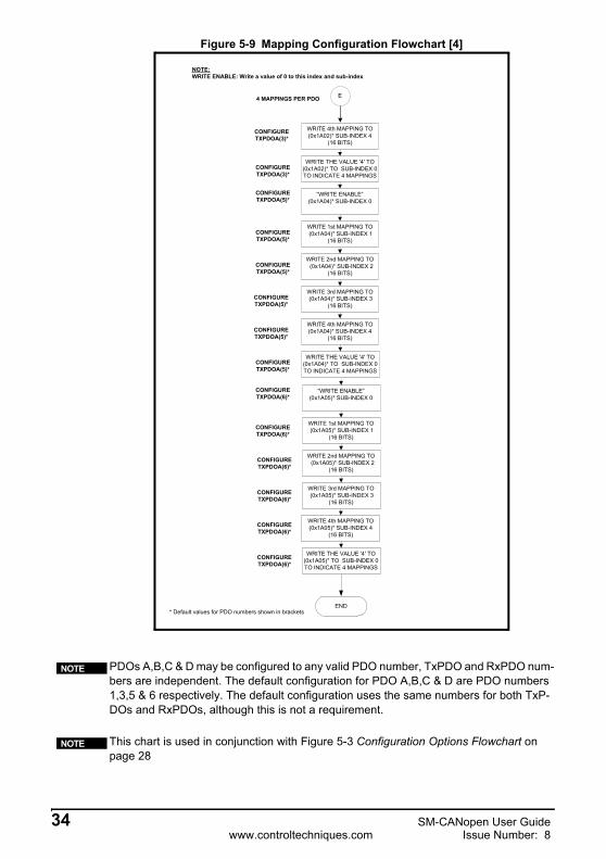
Figure 5-9 Mapping Configuration Flowchart [4]
PDOs A,B,C & D may be configured to any valid PDO number, TxPDO and RxPDO num-bers are independent. The default configuration for PDO A,B,C & D are PDO numbers 1,3,5 & 6 respectively. The default configuration uses the same numbers for both TxP-DOs and RxPDOs, although this is not a requirement.
This chart is used in conjunction with Figure 5-3 Configuration Options Flowchart on page 28
4 MAPPINGS PER PDO
CONFIGURETXPDOA(3)*
CONFIGURETXPDOA(5)*
WRITE 4th MAPPING TO(0x1A02)* SUB-INDEX 4
(16 BITS)
WRITE THE VALUE '4' TO(0x1A02)* TO SUB-INDEX 0TO INDICATE 4 MAPPINGS
“WRITE ENABLE”(0x1A04)* SUB-INDEX 0
WRITE 1st MAPPING TO (0x1A04)* SUB-INDEX 1
(16 BITS)
WRITE 2nd MAPPING TO (0x1A04)* SUB-INDEX 2
(16 BITS)
WRITE 3rd MAPPING TO (0x1A04)* SUB-INDEX 3
(16 BITS)
WRITE 4th MAPPING TO(0x1A04)* SUB-INDEX 4
(16 BITS)
WRITE THE VALUE '4' TO(0x1A04)* TO SUB-INDEX 0TO INDICATE 4 MAPPINGS
CONFIGURETXPDOA(6)*
“WRITE ENABLE”(0x1A05)* SUB-INDEX 0
WRITE 1st MAPPING TO (0x1A05)* SUB-INDEX 1
(16 BITS)
WRITE 2nd MAPPING TO (0x1A05)* SUB-INDEX 2
(16 BITS)
WRITE 3rd MAPPING TO (0x1A05)* SUB-INDEX 3
(16 BITS)
WRITE 4th MAPPING TO(0x1A05)* SUB-INDEX 4
(16 BITS)
WRITE THE VALUE '4' TO(0x1A05)* TO SUB-INDEX 0TO INDICATE 4 MAPPINGS
E
END* Default values for PDO numbers shown in brackets
CONFIGURETXPDOA(3)*
CONFIGURETXPDOA(5)*
CONFIGURETXPDOA(5)*
CONFIGURETXPDOA(5)*
CONFIGURETXPDOA(5)*
CONFIGURETXPDOA(5)*
CONFIGURETXPDOA(6)*
CONFIGURETXPDOA(6)*
CONFIGURETXPDOA(6)*
CONFIGURETXPDOA(6)*
CONFIGURETXPDOA(6)*
NOTE:WRITE ENABLE: Write a value of 0 to this index and sub-index
NOTE
NOTE
34 SM-CANopen User Guidewww.controltechniques.com Issue Number: 8
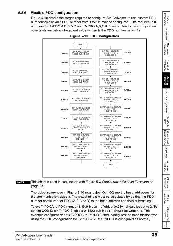
Safety Inform
ationIntroduction
Mechanical
InstallationElectrical
InstallationG
etting Started
EDS Files
Cyclic D
ataN
on-Cyclic
Data
Control and
Status Words
Diagnostics
Advanced Features
CAN
open R
eferenceQ
uick R
eferenceG
lossary Of
Terms
Index
5.8.6 Flexible PDO configurationFigure 5-10 details the stages required to configure SM-CANopen to use custom PDO numbering (any valid PDO number from 1 to 511 may be configured). The required PDO numbers for TxPDO A,B,C & D and RxPDO A,B,C & D are written to the configuration objects shown below (the actual value written is the PDO number minus 1).
Figure 5-10 SDO Configuration
The object references in Figure 5-10 (e.g. object 0x1400) are the base addresses for the communication objects. The actual object must be calculated by adding the PDO number configured for PDO (A,B,C or D) to the base address and then subtracting 1.
To set TxPDOA to PDO number 3, Sub-index 1 of object 0x2801 should be set to 2. To set the COB ID for TxPDO 3, object 0x1802 sub-index 1 should be written to. This example configuration sets TxPDOA to TxPDO 3, then configures the transmission type using the SDO configuration for TxPDO3 (i.e. the TxPDO is configured as normal).
This chart is used in conjunction with Figure 5-3 Configuration Options Flowchart on page 28.
SET COB-ID TxPDOA(0x1800 + PDO -1) SUB-
INDEX 1
SET TRANSMISSION TYPE(0x1800 + PDO -1)
SUB-INDEX 2
SET COB-ID RxPDOD(0x1400 + PDO -1)
SUB-INDEX 1
SET COB-ID RxPDOB(0x1400 + PDO -1)
SUB-INDEX 1
SET COB-ID TxPDOD(0x1800 + PDO -1)
SUB-INDEX 1
SET COB-ID TxPDOC(0x1800 + PDO -1)
SUB-INDEX 1
SET COB-ID TxPDOB(0x1800 + PDO - 1)
SUB-INDEX 1
SET COB-ID RxPDOC(0x1400 +PDO -1)
SUB-INDEX 1
SET TRANSMISSION TYPE(0x1800 + PDO -1)
SUB-INDEX 2
SET TRANSMISSION TYPE(0x1400 + PDO -1)
SUB-INDEX 2
SET TRANSMISSION TYPE(0x1400 + PDO -1)
SUB-INDEX 2
SET TRANSMISSION TYPE(0x1400 + PDO -1)
SUB-INDEX 2
SET TRANSMISSION TYPE(0x1800 + PDO -1)
SUB-INDEX 2
SET TRANSMISSION TYPE(0x1800 + PDO -1)
SUB-INDEX 2
SET TRANSMISSION TYPE(0x1400 +PDO -1)
SUB-INDEX 2
END
SET RxPDO NUMBER0x2800 SUB-INDEX 1RxPDOA
TxPDOA
SET RxPDO NUMBER0x2800 SUB-INDEX 2
SET RxPDO NUMBER0x2800 SUB-INDEX 3
SET RxPDO NUMBER0x2800 SUB-INDEX 4
SET TxPDO NUMBERS0x2801 SUB-INDEX 1
SET TxPDO NUMBERS0x2801 SUB-INDEX 2
SET TxPDO NUMBERS0x2801 SUB-INDEX 3
SET TxPDO NUMBERS0x2801 SUB-INDEX 4
RxPDOB
RxPDOD
RxPDOC
TxPDOB
TxPDOC
TxPDOD
START
TxPDOA
TxPDOB
TxPDOC
TxPDOD
SET COB-ID RxPDOA(0x1400 + PDO -1)
SUB-INDEX 1RxPDOA
RxPDOB
RxPDOD
RxPDOC
TxPDOA
TxPDOB
TxPDOC
TxPDOD
RxPDOA
RxPDOB
RxPDOD
RxPDOC
NOTE
SM-CANopen User Guide 35Issue Number: 8 www.controltechniques.com

5.8.7 Saving SDO setup in SM-CANopenFigure 5-11 details the procedure to save previously sent SDO configuration settings to the SM-CANopen FLASH memory. This removes the requirement to resend configuration SDOs if the CANopen is reset or powered down.
Figure 5-11 Saving SDO setup
5.8.8 Masters with no SDO configuration facility or fixed PDOsSome masters do not support SDO configuration of communication objects or may only support fixed PDO numbers. In this case it may be possible to use an alternative master to configure the module, and performing a save (using object 0x1010) section 12.3.8 Store parameters on page 106. This allows pre-configured CANopen models to be shipped to site after previously being configured. Please see Figure 5-12 for an example SDO configuration.
Figure 5-12 SDO configuration
START
END
OBJECT 0x1010 “WRITESAVE COMMAND”
(see section 12)
36 SM-CANopen User Guidewww.controltechniques.com Issue Number: 8

Safety Inform
ationIntroduction
Mechanical
InstallationElectrical
InstallationG
etting Started
EDS Files
Cyclic D
ataN
on-Cyclic
Data
Control and
Status Words
Diagnostics
Advanced Features
CAN
open R
eferenceQ
uick R
eferenceG
lossary Of
Terms
Index
5.9 SM-CANopen data format
This parameter specifies the number of data words in the RxPDO and TxPDO for the first configured PDO (by default PDOA). To specify different lengths for RxPDO and TxPDO Pr MM.39 and Pr MM.40 should be used.
By default, RxPDOA and TxPDOA are enabled (transmission type 255) with all other PDOs disabled. TxPDOA and RxPDOA consist of two 32-bit channels each, with each channel mapped directly to a drive parameter. Default mappings as shown in Table 5.3.
5.10 Default COB-IDs and transmission type
TxPDOA transmission type defaults to 255. If Pr MM.41 is set to 1 and the SM-CANopen is reset, this will cause the SM-CANopen to transmit TxPDOA in response to every SYNC message received. RxPDOA defaults to transmission type 255, meaning that RxPDOA will be processed immediately when it is received. All transmission types are supported, refer to Chapter 12 CANopen Reference on page 102 for more details.
SM-CANopen data format PDOA (by default PDO1)
Pr MM.05Default 4Range 0 - 4, 100 - 103 & 300*Access RW
*For SM-CANopen firmware 03.01.00 and above, any modifications to the standard configuration for PDOA performed over the SDO protocol will result in the mode parameter (Pr MM.05) being set to 300.
NOTE
TxPDOA and RxPDOA are set to RxPDO1 and RxPDO 1 by default. This parameter will not be used if SM-CANopen is configured by SDOs, in this case a value of 300 will be shown.
Table 5.3 SM-CANopen default data mapping
Polled channel Data word Mapping parameter Default mapping status
IN channel 0 Word 0, 1 Pr MM.10 1040 (Pr 10.40, status word)IN channel 1 Word 2, 3 Pr MM.11 201 (Pr 2.01, post-ramp speed ref)
OUT channel 0 Word 0, 1 Pr MM.20 642 (Pr 6.42, control word)OUT channel 1 Word 2, 3 Pr MM.21 121 (Pr 1.21, digital speed ref 1)
For information on setting up more than PDOA (1) please see section 5.6 Types of set-up on page 24.
NOTE
NOTE
SM-CANopen TxPDOA (TxPDO1 by default) transmission type
Pr MM.41Default 255Range 0 to 255Access RW
SM-CANopen User Guide 37Issue Number: 8 www.controltechniques.com
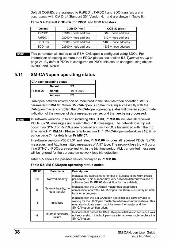
Default COB-IDs are assigned to RxPDO1, TxPDO1 and SDO transfers are in accordance with CiA Draft Standard 301 Version 4.1 and are shown in Table 5.4.
5.11 SM-CANopen operating status
CANopen network activity can be monitored in the SM-CANopen operating status parameter Pr MM.06. When SM-CANopen is communicating successfully with the CANopen master controller, the SM-CANopen operating status will give an approximate indication of the number of data messages per second that are being processed.
Table 5.5 shows the possible values displayed in Pr MM.06.
Table 5.4 Default COB-IDs for PDO1 and SDO transfers
Object COB-ID (hex.) COB-ID (dec.)TxPDO1 0x180 + node address 384 + node addressRxPDO1 0x200 + node address 512 + node addressSDO (tx) 0x580 + node address 1408 + node addressSDO (rx) 0x600 + node address 1536 + node address
This parameter will not be used if SM-CANopen is configured using SDOs. For information on setting up more than PDOA please see section 5.6 Types of set-up on page 24. By default PDOA is configured as PDO1 this can be changed using objects 0x2800 and 0x2801.
NOTE
CANopen operating status
Pr MM.06Default N/ARange -10 to 9999Access RO
In software versions up to and including V03.01.00, Pr MM.06 includes all received PDOs, SYNC messages and transmitted PDO messages. The network loss trip will occur if no SYNC or RxPDOs are received and no TxPDOs transmitted within the trip time period (Pr MM.07). Please refer to section 11.1 SM-CANopen network loss trip time-out on page 74 for details on Pr MM.07.In software versions V03.01.01 and later, Pr MM.06 includes all received PDOs, SYNC messages, and ALL transmitted messages of ANY type. The network loss trip will occur if no SYNC or PDOs are received within the trip time period. ALL transmitted messages will be ignored for the purpose on network loss trip detection.
Table 5.5 SM-CANopen operating status codes
MM.06 Parameter Description
>0 Network healthyIndicates the approximate number of successful network cycles per second. This number may vary between different versions of software (see Pr MM.06 description for more details).
0 Network healthy, no data transfer
Indicates that the CANopen master has established communications with SM-CANopen, but there is currently no data transfer in progress.
-1 Initialised
Indicates that the SM-CANopen has initialised correctly and is waiting for the CANopen master to initialise communications. This may also indicate a mismatch between the master and the SM-CANopen configuration.
-2 Internal hardware failure
Indicates that part of the SM-CANopen initialisation sequence was not successful. If this fault persists after a power cycle, replace the SM-CANopen.
NOTE
38 SM-CANopen User Guidewww.controltechniques.com Issue Number: 8

Safety Inform
ationIntroduction
Mechanical
InstallationElectrical
InstallationG
etting Started
EDS Files
Cyclic D
ataN
on-Cyclic
Data
Control and
Status Words
Diagnostics
Advanced Features
CAN
open R
eferenceQ
uick R
eferenceG
lossary Of
Terms
Index
5.12 Resetting the SM-CANopen (re-initialising)
Changes to the SM-CANopen configuration in menu 15 (15, 16 and 17 for Unidrive SP) parameters will not take effect until the SM-CANopen has been reset.To reset SM-CANopen:1. Set Pr MM.32 to ON.2. When the reset sequence has been completed, Pr MM.32 will be reset to OFF (the
change to 1 may not be visible).3. The SM-CANopen will re-initialise using the updated configuration.
5.13 Unidrive SP: reset Solutions Modules To reset all Solutions Modules fitted:1. Set Pr MM.00 to 1070.Press the red RESET button on the drive.
5.14 Storing SM-CANopen configuration parametersMenu 15 (menu 15, 16 and 17 on Unidrive SP) parameters are stored in the host drive. The SM-CANopen will always use these values during initialisation to configure itself, so if a new SM-CANopen is fitted to the same slot, it will communicate using the same settings as the previous SM-CANopen (this will not retrieve the communication parameters (SDO configuration), see Chapter 12 CANopen Reference on page 102 for more information).
If the stored values in the host drive are for a different type of Solutions Module, the host drive will trip. The slot configuration parameters will be set to default values for SM-CANopen, but the default values will NOT be stored in the host drive.
-3 Configuration error
Indicates that there is an invalid setting in the SM-CANopen configuration parameters See section 10.6SM-CANopen mapping status on page 69 and 10.7SM-CANopen error code on page 72 for further diagnostic details.
-4 Unrecoverable software error
An internal software error has occurred. Reset the SM-CANopen to clear, if error persists, replace the SM-CANopen.
-8 Data rate detection in progress
The SM-CANopen is currently attempting to detect the CANopen network data rate.
-10 Device disabled Indicates that the DS301 V1.1 CANopen communications layer has been disabled by setting the node address to 0.
Table 5.5 SM-CANopen operating status codes
MM.06 Parameter Description
SM-CANopen reset
Pr MM.32Default 0 (OFF)Range 0 (OFF) to 1 (ON)Access RW
This sequence does NOT store SM-CANopen configuration parameters or SDO setup in the drive or the SM-CANopen FLASH memory. See section 5.14 Storing SM-CANopen configuration parameters on page 39 for more information.
NOTE
This sequence does NOT store the SM-CANopen configuration parameters or communication settings (SDO set-up) in the drive or the SM-CANopen FLASH memory. See section 5.14 Storing SM-CANopen configuration parameters for more information.
NOTE
SM-CANopen User Guide 39Issue Number: 8 www.controltechniques.com

The SM-CANopen configuration parameters can also be stored in the FLASH memory on the SM-CANopen. If the drive is replaced, the SM-CANopen configuration parameters can subsequently be restored to the new drive.
5.14.1 Saving parameters on Unidrive SP/Commander SKThis procedure stores the operating parameters for the SM-CANopen to the drive’s internal memory. To store parameters in the host drive:1. Set Pr MM.00 to 1000 (a Unidrive SP on 24V supply only requires a value of 1001).2. Press the red RESET button.The drive will store all parameters, (except Menu 20 unless SM-Applications/SM-Applications Lite is fitted and configured appropriately) but the operation of the SM-CANopen will not be affected. Changes made to the SM-CANopen configuration parameters will not take effect until the SM-CANopen is reset (Pr MM.32).
5.14.2 Back-up parameters to SM-CANopen FLASH memoryThis procedure can be used to transfer settings to a new drive from a previously configured SM-CANopen module. To store the SM-CANopen configuration parameters in the FLASH memory in the SM-CANopen:
1. Set Pr MM.31 to ON.
2. Set Pr MM.00 to 1000 (a Unidrive SP on 24V only requires a value of 1001).*
3. Press the red RESET button.*
The host drive will store its parameters, and CANopen communication will be halted immediately. The SM-CANopen configuration parameters will be saved within the FLASH memory. The SM-CANopen will then reset and re-initialise using the updated configuration parameter values.
5.15 Restore SM-CANopen defaults
This procedure can be used to default the CANopen module to factory settings, this will also default the drive settings. If the SM-CANopen detects that the host drive has been restored to default values, it will over-write the slot configuration parameters with the SM-CANopen default values. This will also clear any SDO configuration previously saved with object 0x1010.
Pr MM.30 specifies whether the default values should be written to the SM-CANopen FLASH memory when the host drive is defaulted. If Pr MM.30 is set to ON, the default values will be written into the SM-CANopen FLASH memory.
The full sequence of events to restore default settings for a SM-CANopen is as follows:
To save parameters from SM-CANopen to the memory on Commander SX, press M key.NOTE
To save parameters from SM-CANopen to the memory on Commander SX, press M key. * Steps 2 and 3 are not required on Commander SX.
NOTE
Restore SM-CANopen defaults
Pr MM.30Default OFF (0)Range OFF (0) or ON (1)Access RW
If the stored values in the drive are for a different type of Solutions Module, the SM-CANopen will trip “SLx.DF”, but no error code will be set. It will over-write the parameter values with the SM-CANopen default values, but will NOT store these values in the drive.
NOTE
40 SM-CANopen User Guidewww.controltechniques.com Issue Number: 8

Safety Inform
ationIntroduction
Mechanical
InstallationElectrical
InstallationG
etting Started
EDS Files
Cyclic D
ataN
on-Cyclic
Data
Control and
Status Words
Diagnostics
Advanced Features
CAN
open R
eferenceQ
uick R
eferenceG
lossary Of
Terms
Index
1. Set Pr MM.30 to 1.
2. Unidrive SP - Set Pr MM.00 to 1233 to restore European defaults (1244 for USA defaults). Commander SK - Set Pr 00.29 to EUR for European defaults (USA for American defaults). Commander SX - Set Pr 00.65 to Eur for European defaults (USA for American defaults).
3. Press the red reset button on the drive.
4. CANopen communications will be stopped.
5. The host drive will load and store its default parameter values.
6. Default parameter values for the SM-CANopen will be loaded in Pr MM.xx parameters.
7. The SM-CANopen default parameter values will be stored in the SM-CANopen FLASH memory.
8. SM-CANopen will reset and re-initialise using the default values.
5.16 Restore previous SM-CANopen configuration
If valid configuration parameters have previously been stored in the SM-CANopen FLASH memory, these values can be restored to the host drive. When the configuration parameter values have been uploaded to the host drive, the SM-CANopen will reset and re-configure itself using the updated parameter values. Object 0x1010 additionally allows the communication object settings sent by a master to be saved.
This feature allows a pre-configured SM-CANopen to be fitted to a host drive without losing the SM-CANopen configuration. If the SM-CANopen is unable to upload the configuration parameters to the host drive, or configuration parameters have never been stored in the SM-CANopen FLASH memory, the host drive will trip and set the error code (Pr MM.49) to 70.
When Pr MM.33 is set to ON, the SM-CANopen will transfer the configuration parameters from its FLASH memory to the host drive, over-writing the existing values in the host drive.
The full sequence of events for restoring values from a SM-CANopen is as follows:
1. Set Pr MM.33 to ON.
2. CANopen communications will be stopped.
3. The SM-CANopen will overwrite all Pr MM.xx parameters with the values stored in its internal FLASH memory.
4. Pr MM.33 will be reset to OFF.
5. The SM-CANopen will reset and re-initialise using the restored values.
The drive settings will also be defaulted with the above procedure.NOTE
Upload from SM-CANopen FLASH memory
Pr MM.33Default OFF (0)Range OFF (0) or ON (1)Access RW
SM-CANopen User Guide 41Issue Number: 8 www.controltechniques.com

This procedure will NOT store the updated host drive parameters, to do this a drive save must be performed.
The SM-CANopen will restore its configuration parameters to the menu of parameters associated with the slot that it is installed in. If an SM-CANopen is moved from slot 3 on a Unidrive SP, it can be re-installed in any slot on another Unidrive SP using this procedure.
NOTE
42 SM-CANopen User Guidewww.controltechniques.com Issue Number: 8

Safety Inform
ationIntroduction
Mechanical
InstallationElectrical
InstallationG
etting Started
EDS Files
Cyclic D
ataN
on-Cyclic
Data
Control and
Status Words
Diagnostics
Advanced Features
CAN
open R
eferenceQ
uick R
eferenceG
lossary Of
Terms
Index
6 EDS Files6.1 What are EDS files?
An EDS (Electronic Data Sheet) file is an ASCII text file, which can be opened, edited, and saved in a simple text editor such as Microsoft Notepad. Before altering an EDS file ensure you have saved a copy of the original file. To maintain good backup practice it is recommended that you rename a copy of the file you wish to edit in the following format:
OriginalName_YourCompanyName_RevisionNumber.EDS
EDS files are used by some CANopen network configuration tools. They contain information about the objects supported by the drive. EDS files are normally only used during network configuration (some CANopen master controllers do not use EDS files at all).
6.2 Supplied EDS filesThe files listed in Table 6.1 are generic files that will support a drive fitted withSM-CANopen and an SM-Applications (where fitted). SM-CANopen and SM-Applications configuration parameters are accessed as Pr 60.XX and Pr 81.XX respectively, as this allows the modules to be fitted in any slot and the EDS file will still work. The EDS files are available directly from your supplier or local drive centre.
Generic EDS files are not strictly conformant to the CANopen EDS file specification, as some drive parameters are not listed. For example, if SM-CANopen is fitted in slot 1 and SM-Applications is fitted in slot 2, the configuration parameters for slot 3(Pr 17.PP) cannot be accessed.
Table 6.1 Generic SM-CANopen EDS files
Drive Drive mode
Additional modules
Data compression
DSP402 profiles EDS filename
Unidrive SP Open loop None OFF Disabled USPOL_G.EDSUnidrive SP Open loop SM-Apps OFF Disabled USPOL_GAP.EDSUnidrive SP Open loop None ON Disabled USPOL_G_DC.EDSUnidrive SP Open loop SM-Apps ON Disabled USPOL_GAP_DC.EDSUnidrive SP Open loop None ON Enabled USPOL_G_DCDP.EDSUnidrive SP Open loop SM-Apps ON Enabled USPOL_GAP_DCDP.EDS
Unidrive SP Closed loop None OFF Disabled USPCL_G.EDS
Unidrive SP Closed loop SM-Apps OFF Disabled USPCL_GAP.EDS
Unidrive SP Closed loop None ON Disabled USPCL_G_DC.EDS
Unidrive SP Closed loop SM-Apps ON Disabled USPCL_GAP_DC.EDS
Unidrive SP Closed loop None ON Enabled USPCL_G_DCDP.EDS
Unidrive SP Closed loop SM-Apps ON Enabled USPCL_GAP_DCDP.EDS
Unidrive SP Servo None OFF Disabled USPSV_G.EDSUnidrive SP Servo SM-Apps OFF Disabled USPSV_GAP.EDSUnidrive SP Servo None ON Disabled USPSV_G_DC.EDSUnidrive SP Servo SM-Apps ON Disabled USPSV_GAP_DC.EDS
NOTE
SM-CANopen User Guide 43Issue Number: 8 www.controltechniques.com

Bitmap files are supplied with the EDS files for use with the CANopen configuration software on the master. Refer to the master configuration software documentation for instructions on how to install EDS files. Control Techniques cannot provide specific technical support for any of these CANopen configuration packages.
6.3 Changing EDS files/customisationNormally it is not necessary to change EDS files however in certain circumstances it may be necessary to do this (in particular with certain combinations of modules on the Unidrive SP).
Unidrive SP Servo None ON Enabled USPSV_G_DCDP.EDSUnidrive SP Servo SM-Apps ON Enabled USPSV_GAP_DCDP.EDS
Commander SK Open loop None OFF Disabled CSK_G.EDSCommander SK Open loop None ON Disabled CSK_G_DC.EDSCommander SK Open loop None ON Enabled CSK_G_DCDP.EDSCommander SX Open loop None OFF Disabled PXOL_G.EDS
Commander SX Closed loop None OFF Disabled PXCL_G.EDS
Table 6.1 Generic SM-CANopen EDS files
Drive Drive mode
Additional modules
Data compression
DSP402 profiles EDS filename
44 SM-CANopen User Guidewww.controltechniques.com Issue Number: 8

Safety Inform
ationIntroduction
Mechanical
InstallationElectrical
InstallationG
etting Started
EDS Files
Cyclic D
ataN
on-Cyclic
Data
Control and
Status Words
Diagnostics
Advanced Features
CAN
open R
eferenceQ
uick R
eferenceG
lossary Of
Terms
Index
7 Cyclic Data
7.1 What is a “Process Data Object”?Cyclic data is implemented on CANopen networks by using “process data objects” or PDOs. Separate data objects are used for transmitting (TxPDOs) and receiving (RxPDOs) data. PDO configuration objects are usually pre-configured in the CANopen master controller and downloaded to the SM-CANopen at network initialisation using SDOs.
Mapping parameters are provided that can be used to configure RxPDO1 and TxPDO1 in SM-CANopen (or the first configured PDO (A) if this has been changed using objects 0x2800 or 0x2801). These parameters are used to set default values in the PDO mapping objects during initialisation.
7.2 SM-CANopen data format
This parameter specifies the number of data words (16 bit) in the RxPDO and TxPDO for the first configured PDO (PDOA which by default is PDO1). Pr MM.05 is used when configuring a single PDO using the slot parameters (Pr MM.xx) only. To specify different lengths for RxPDOA and TxPDOA Pr MM.39 and Pr MM.40 should be used instead, this however, is not normally required. SM-CANopen can be configured with up to 4 data words (16 bit) on TxPDOA and 4 data words (16 bit) on RxPDOA. These data words may be configured using mapping parameters (Pr MM.xx) for PDOA only, or alternatively all PDOs (A,B,C & D) may be configured using SDOs from the master. See Chapter 5.3 Flexible PDO Numbering (software compatibility) on page 23 for more information on PDO numbering.A value of 100-103 indicates that the first cyclic channel is used for CT mode 1 (non-cyclic) communications. Chapter 8.2 Mode 1 - CT Single Word mode on page 52 gives more information on configuring CT mode 1 non-cyclic data.
Slot parameters (Pr MM.xx) are only required for configuration of the first PDO when configuration is done without SDOs. Configuration would normally be done with SDOs, if supported by the master.
If the CANopen master controller over-writes the mapping objects, the mapping parameters are NOT automatically updated to indicate the new mappings, in the corresponding slot menus. TxPDO and RxPDO describe the direction of data transfer as seen by the slave devices on a CANopen network. By default TxPDOA (default TxPDO1) is configured as transmission type 255.
NOTE
NOTE
SM-CANopen data format PDOA (by default PDO1)
Pr MM.05Default 4Range 0-4, 100-103,300*Access RW
*For SM-CANopen firmware 03.01.01 and above, any modifications to the standard configuration for PDOA performed over the SDO protocol will result in the mode parameter (Pr MM.05) being set to 300.
NOTE
SM-CANopen User Guide 45Issue Number: 8 www.controltechniques.com

7.3 Data size on the networkDepending upon the size of the source/destination parameter, the size of the data on the network (PDO or SDO) will vary according to the state of Pr MM.34 (data compression). When data compression is enabled (by setting Pr MM.34 = ON) a mapping will use 32 bits if the target drive parameter is a 32 bit parameter. If the target drive parameter for a mapping is only 1, 8 or 16 bits, only 16 bits will be used for that particular mapping (see section 11.8 Cyclic data compression on page 80 for more information). This effectively enables 4 mappings per PDO with compression on and 16 bit (or less) mappings as opposed to 2 with compression off or 32 bit mappings (see Figure 7-1 for more details).
Figure 7-1 Data compression - parameters / network data size
7.4 Default settingsThe following details only apply to a PDO configured using parameters in SM-CANopen (Pr MM.xx). The setup flowcharts in Chapter 5.6 Types of set-up on page 24 detail the setup procedure if the PDO is configured using SDOs.
The SM-CANopen data format for RxPDOA and TxPDOA (which is by default PDO1) is specified as “NPP”, where N is the non-cyclic data mode, and PP is the number of data words.
The reference for the source or target parameter is entered in the mapping parameter in the form MMPP, where MM = menu number of the target/source parameter and PP = parameter number of the target/source parameter.
32 bit *
16 bit
Size of Data on NetworkMM.34 = 1(on)
Source/DestinationParameter Size
1 bit
* 32 bit parameters do not compress 16 bit parameters (or less) compress to 16 bit
32 bit * 32 bit *
16 bit32 bit
32 bit
32 bit 16 bit
16 bit8 bit
MM.34 = 1(off)
Table 7.1 Valid SM-CANopen data formats
Pr MM.05 N PP Non-cyclic mode Cyclic words
0 0 0Refer to section 11.10 PDOA length on page 81 or
section 12.15.1 Enable DSP402 device profiles on page 133
1 to 4 0 1 to 4 SDO only 1 to 4100 to 103 1 0 to 3 SDO plus CT Single Word 0 to 3
300 Indicates that the configuration is provided from the master
46 SM-CANopen User Guidewww.controltechniques.com Issue Number: 8

Safety Inform
ationIntroduction
Mechanical
InstallationElectrical
InstallationG
etting Started
EDS Files
Cyclic D
ataN
on-Cyclic
Data
Control and
Status Words
Diagnostics
Advanced Features
CAN
open R
eferenceQ
uick R
eferenceG
lossary Of
Terms
Index
When the data format is configured using Pr MM.05, SM-CANopen will communicate using the same number of data words for RxPDOA and TxPDOA. It is, however, possible to configure SM-CANopen to communicate with different numbers of words for TxPDOA and RxPDOA. Refer to section 11.10 PDOA length on page 81 for full details.
The following sections show some example data formats that can be selected and the parameter mapping that will apply (by default) to each format.
7.4.1 PDOA 2 channels (default) - standard mappings
This data format provides 2 data channels on TxPDOA (by default TxPDO1) and RxPDOA (by default RxPDO1) with no non-cyclic data channel. The total data length is 4 words or 8 bytes. To select this data format, set Pr MM.05 = 4. This data format is selected by default.
Table 7.2 SM-CANopen PDO default mapping parameters
IN channelTxPDOA
Mapping parameter OUT channelRxPDOA
Mapping parameter
Slot Slot
0 Pr MM.10 0 Pr MM.201 Pr MM.11 1 Pr MM.212 Pr MM.12 2 Pr MM.223 Pr MM.13 3 Pr MM.23
If a mapping parameter is set to an invalid value (e.g. destination parameter is read only, or parameter does not exist) SM-CANopen will indicate “-3” in the operating status parameter (Pr MM.06). The reason for the mapping error will be indicated by the mapping status parameter (Pr MM.49), refer to section 10.6 SM-CANopen mapping status on page 69 for more details.
The IN channel referred to in Table 7.2 is from the perspective of the PLC i.e. referencing data flowing into the PLC.
NOTE
PDO data channels do not use decimal points. For example, in open loop mode, the Unidrive SP digital speed reference 1 (Pr 1.21) has units of Hertz, accurate to 1 decimal place. To write a value of 24.6Hz to Pr 1.21, the value must be transmitted as 246.
NOTE
Table 7.3 Mapping for PDO1 - 2 channels in and out
Data word Parameter Default mapping statusIN word 0, 1,
(TxPDO) Pr MM.10 Pr 10.40, status word
IN word 2, 3(TxPDO) Pr MM.11 Pr 2.01, post-ramp speed reference
OUT word 0, 1(RxPDO) Pr MM.20 Pr 6.42, control word
OUT word 2, 3(RxPDO) Pr MM.21 Pr 1.21, digital speed reference 1
SM-CANopen User Guide 47Issue Number: 8 www.controltechniques.com
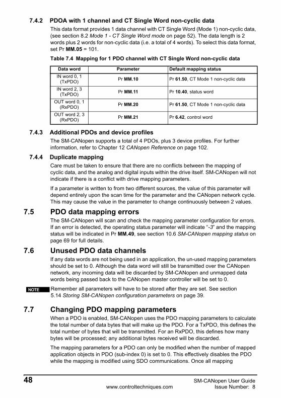
7.4.2 PDOA with 1 channel and CT Single Word non-cyclic dataThis data format provides 1 data channel with CT Single Word (Mode 1) non-cyclic data, (see section 8.2 Mode 1 - CT Single Word mode on page 52). The data length is 2 words plus 2 words for non-cyclic data (i.e. a total of 4 words). To select this data format, set Pr MM.05 = 101.
7.4.3 Additional PDOs and device profilesThe SM-CANopen supports a total of 4 PDOs, plus 3 device profiles. For further information, refer to Chapter 12 CANopen Reference on page 102.
7.4.4 Duplicate mappingCare must be taken to ensure that there are no conflicts between the mapping of cyclic data, and the analog and digital inputs within the drive itself. SM-CANopen will not indicate if there is a conflict with drive mapping parameters.
If a parameter is written to from two different sources, the value of this parameter will depend entirely upon the scan time for the parameter and the CANopen network cycle. This may cause the value in the parameter to change continuously between 2 values.
7.5 PDO data mapping errorsThe SM-CANopen will scan and check the mapping parameter configuration for errors. If an error is detected, the operating status parameter will indicate “-3” and the mapping status will be indicated in Pr MM.49, see section 10.6 SM-CANopen mapping status on page 69 for full details.
7.6 Unused PDO data channelsIf any data words are not being used in an application, the un-used mapping parameters should be set to 0. Although the data word will still be transmitted over the CANopen network, any incoming data will be discarded by SM-CANopen and unmapped data words being passed back to the CANopen master controller will be set to 0.
7.7 Changing PDO mapping parametersWhen a PDO is enabled, SM-CANopen uses the PDO mapping parameters to calculate the total number of data bytes that will make up the PDO. For a TxPDO, this defines the total number of bytes that will be transmitted. For an RxPDO, this defines how many bytes will be processed; any additional bytes received will be discarded.
The mapping parameters for a PDO can only be modified when the number of mapped application objects in PDO (sub-index 0) is set to 0. This effectively disables the PDO while the mapping is modified using SDO communications. Once all mapping
Table 7.4 Mapping for 1 PDO channel with CT Single Word non-cyclic data
Data word Parameter Default mapping statusIN word 0, 1
(TxPDO) Pr MM.10 Pr 61.50, CT Mode 1 non-cyclic data
IN word 2, 3(TxPDO) Pr MM.11 Pr 10.40, status word
OUT word 0, 1(RxPDO) Pr MM.20 Pr 61.50, CT Mode 1 non-cyclic data
OUT word 2, 3(RxPDO) Pr MM.21 Pr 6.42, control word
Remember all parameters will have to be stored after they are set. See section 5.14 Storing SM-CANopen configuration parameters on page 39.
NOTE
48 SM-CANopen User Guidewww.controltechniques.com Issue Number: 8

Safety Inform
ationIntroduction
Mechanical
InstallationElectrical
InstallationG
etting Started
EDS Files
Cyclic D
ataN
on-Cyclic
Data
Control and
Status Words
Diagnostics
Advanced Features
CAN
open R
eferenceQ
uick R
eferenceG
lossary Of
Terms
Index
parameters have been updated, the PDO sub-index 0 is set to specify the total number of defined mappings (normally 4 or 2). SM-CANopen will calculate the PDO length from the mappings, and activate the changes to the PDO mappings.
7.8 Blank mapping parametersIf multiple SM-CANopen nodes are configured with the same COB-ID for an RxPDO, they will all receive the RxPDO at the same time. For example, in a system of 4 drives, RxPDO1 could be used to transmit a 16-bit speed reference to each node.
However, the RxPDO1 mapping in each node must be configured to use only one word received on RxPDO1, and discard all other words. This can be achieved by creating a “blank mapping”. For an RxPDO, data with a blank mapping will simply be discarded. TxPDO data values with a blank mapping will be set to 0.
Unwanted data should be mapped to the DEFTYPE object of appropriate size. Bytes, words and double words are supported, but the BOOLEAN TYPE IS NOT SUPPORTED. The only other limitation is that there are only 4 mapping parameters per PDO, due to memory restrictions.
For example, consider RxPDOA (by default PDO1) containing four 16-bit speed references, one each for 4 different nodes. If a node needs to access only the 3rd word of RxPDOA and map it to Pr 18.11, while ignoring the remaining words, the mapping configuration required is shown in Table 7.6.
Table 7.5 Blank mapping objects
Index Object code Name Type Access PDO
mapping0x0002 DEFTYPE INTEGER8 INTEGER8 RW Yes0x0003 DEFTYPE INTEGER16 INTEGER16 RW Yes0x0004 DEFTYPE INTEGER32 INTEGER32 RW Yes0x0005 DEFTYPE UNSIGNED8 UNSIGNED8 RW Yes0x0006 DEFTYPE UNSIGNED16 UNSIGNED16 RW Yes0x0007 DEFTYPE UNSIGNED32 UNSIGNED32 RW Yes
Table 7.6 Example of blank mapping objects
Word Object Value0 0x1600sub1 0x000300101 0x1600sub2 0x000300102 0x1600sub3 0x20120B103 0x1600sub4 0x00030010
Blank mapping objects allow the mappings to contain null references that are not possible by other means.
NOTE
SM-CANopen User Guide 49Issue Number: 8 www.controltechniques.com

8 Non-Cyclic DataSM-CANopen provides two different methods to implement non-cyclic data. The “Service Data Object” or SDO provides the non-cyclic data channel on a CANopen system and allows access to all objects in the SM-CANopen object dictionary. Object access using SDO is controlled entirely by the master controller program.
CT Mode 1 (single word) non-cyclic data is also available on SM-CANopen. This method uses a single word of the TxPDO and RxPDO, to implement the CT Single Word protocol, allowing access to any drive parameter (see section 8.2 Mode 1 - CT Single Word mode on page 52 for more information).
Non-cyclic data transfer is implemented entirely in the CANopen master, for this reason, Control Techniques is unable to offer any specific technical support with implementing non-cyclic data transfer for any particular CANopen master.
8.1 Service data object (SDO) parameter accessThe service data object (SDO) provides access to all objects in the CANopen object dictionary and the drive parameters are mapped into the object dictionary as 0x2XXX objects in the following way:
Index: 0x2000 + menuSub-index: parameter
For example Pr 20.21 would be index 0x2014 and the sub-index would be 0x15. The values are usually expressed in base 16, so care must be taken to enter the correct parameter number.All other supported entries in the SM-CANopen object dictionary can also be accessed using SDOs. See Chapter 12 CANopen Reference on page 102 for a full list of supported objects. Refer to the master controller documentation for full details about implementing SDO transfers within the particular master controller.
When accessing drive parameters using an SDO, all parameters must be treated as signed 32-bit parameters. If the target parameter is a 16-bit parameter, the data value will be cast to a 32-bit integer. The sign of the 16-bit value will be preserved.
Table 8.1 SM-CANopen non-cyclic data modes
Non-cyclic mode Format Pr MM.05 Non-cyclic access
Disabled None 0PP SDO onlyMode 1 CT Single Word 1PP SDO plus CT Single Word
The non-cyclic data channel does not use decimal points. For example, in open loop mode, digital speed reference 1 (Pr 1.21) has units of Hertz, accurate to 1 decimal place. To write a value of 24.6Hz to Pr 1.21, the value must be transmitted as 246.
NOTE
Sub-index 0 for any menu will return the highest sub-index available for the object (i.e. the highest parameter number). Pr xx.00 in any drive can only be accessed as Pr 61. 01. Commander SX does not support this functionality.
NOTE
50 SM-CANopen User Guidewww.controltechniques.com Issue Number: 8
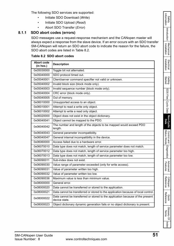
Safety Inform
ationIntroduction
Mechanical
InstallationElectrical
InstallationG
etting Started
EDS Files
Cyclic D
ataN
on-Cyclic
Data
Control and
Status Words
Diagnostics
Advanced Features
CAN
open R
eferenceQ
uick R
eferenceG
lossary Of
Terms
Index
The following SDO services are supported:• Initiate SDO Download (Write)• Initiate SDO Upload (Read)• Abort SDO Transfer (Error)
8.1.1 SDO abort codes (errors)SDO messages use a request-response mechanism and the CANopen master will always expect a response from the slave device. If an error occurs with an SDO transfer SM-CANopen will return an SDO abort code to indicate the reason for the failure, the SDO abort codes are listed in Table 8.2.
Table 8.2 SDO abort codes
Abort code(in hex.) Description
0x05030000 Toggle bit not alternated.0x05040000 SDO protocol timed out.0x05040001 Client/server command specifier not valid or unknown.0x05040002 Invalid block size (block mode only).0x05040003 Invalid sequence number (block mode only).0x05040004 CRC error (block mode only).0x05040005 Out of memory.0x06010000 Unsupported access to an object.0x06010001 Attempt to read a write only object.0x06010002 Attempt to write a read only object.0x06020000 Object does not exist in the object dictionary.0x06040041 Object cannot be mapped to the PDO.
0x06040042 The number and length of the objects to be mapped would exceed PDO length.
0x06040043 General parameter incompatibility.0x06040047 General internal incompatibility in the device.0x06060000 Access failed due to a hardware error.0x06070010 Data type does not match, length of service parameter does not match.0x06070012 Data type does not match, length of service parameter too high.0x06070013 Data type does not match, length of service parameter too low.0x06090011 Sub-index does not exist.0x06090030 Value range of parameter exceeded (only for write access).0x06090031 Value of parameter written too high.0x06090032 Value of parameter written too low.0x06090036 Maximum value is less than minimum value.0x08000000 General error.0x08000020 Data cannot be transferred or stored to the application.0x08000021 Data cannot be transferred or stored to the application because of local control.
0x08000022 Data cannot be transferred or stored to the application because of the present device state.
0x08000023 Object dictionary dynamic generation fails or no object dictionary is present.
SM-CANopen User Guide 51Issue Number: 8 www.controltechniques.com

8.2 Mode 1 - CT Single Word modeThe CT Single Word (Mode 1) uses one cyclic channel for non-cyclic data. The non-cyclic sub-protocol for the drive requires a specific sequence of 4 or 6 telegrams to implement the parameter access. Each non-cyclic word or telegram is split into 2 bytes to implement the sub-protocol, with the high byte containing the control codes for each telegram, and the low byte containing the data for each telegram.
8.2.1 Mapping for CT Single Word non-cyclic data (using Pr MM.xx)To configure an SM-CANopen for CT Single Word Mode non-cyclic data, the following steps must be performed:
1. Set Pr MM.05 to the required mode.
2. Set Pr MM.32 to ON to reset and re-initialise SM-CANopen.
When SM-CANopen re-initialises it will map cyclic data IN Word 0 and OUT Word 0 to the CT Single Word protocol parameter Pr 61.50. All existing mapping parameters will be moved down by 1 word, i.e. the previous mapping set in Pr MM.10 and Pr MM.20 will now appear in Pr MM.11 and Pr MM.21. Parameter Pr 61.50 may be mapped using either SDOs from the master or the slot menu (Pr MM.xx).
8.2.2 CT Single Word protocolAll parameter values for the drive must be written as signed 32-bit data values. Decimal point information is inserted automatically when the data value is written to the drive, and removed when the data value is read. It is important that the number of decimal places of the target parameter is known to prevent scaling errors.For example writing a value of 1234 to a parameter with 2 decimal places will produce a value of 12.34 in the target parameter, reading a value of 12.34 will return a 32-bit integer value of 1234.Table 8.3 shows the bit allocations for CT Single word protocol.
Table 8.3 CT Single Word bit allocation
If cyclic data compression is disabled, the CT Single Word non-cyclic channel will be 32-bits wide, i.e. uses 2 words, and data must be transferred on the low word. If cyclic data compression is enabled, the CT Single Word non-cyclic channel will revert to 16-bits and only use 1 word.
NOTE
If all IN (TxPDO) or OUT (RxPDO) mapping parameters are being used when the data format change is implemented, the last mapping parameter value will be lost.
It is possible to map the non cyclic channel (Mode 1) using SDOs to the appropriate mapping object. A mapping is required for both the IN (TxPDO) and OUT (RxPDO) word and may be contained in any PDO.
NOTE
NOTE
b15 b14 b13 b12 b11 b10 b9 b8READ ERR Reserved 32-BIT Stamp Number
b7 b6 b5 b4 b3 b2 b1 b0Data Byte
52 SM-CANopen User Guidewww.controltechniques.com Issue Number: 8

Safety Inform
ationIntroduction
Mechanical
InstallationElectrical
InstallationG
etting Started
EDS Files
Cyclic D
ataN
on-Cyclic
Data
Control and
Status Words
Diagnostics
Advanced Features
CAN
open R
eferenceQ
uick R
eferenceG
lossary Of
Terms
Index
8.2.3 16-bit parameter access16-bit data can be used to access parameters within the drive using only 4 telegrams. If an attempt is made to read a 32-bit parameter from the drive, the parameter value will be returned, provided that the parameter value does not exceed a signed 16-bit limits. If the value is larger than a signed 16-bit value, the ERR bit will be set. When writing data to a 32-bit parameter, the 16-bit data will be treated as a signed 16-bit data value. This limits the range that can be written to a 32-bit parameter.
Table 8.4 CT Single Word format
Bit Function Values Description
0 to 7 Data 0 to 255 Depending on the stamp number of the telegram, this byte contains the menu, parameter or data byte.
8 to 11 Stamp number 0 to 6
Indicates the stamp number of the word. This shows which part of the message is currently in progress. Setting the stamp number to 0 resets the internal non-cyclic state machine.
12 32-BIT 0 = 16-bit data1 = 32-bit data
Specifies whether a 16-bit or 32-bit data value is to be written to or read from the drive. If 32-BIT is set, telegrams 5 and 6 will be used to transfer the additional data bytes.
13 Reserved 0 Reserved for future use. Always set to 0.
14 ERR 0 = Data OK1 = Error
Indicates the success or failure of the message. Failure could occur if the parameter does not exist, or is a read-only/write-only parameter. This bit will also be set if the parameter value is out of range in 16-bit mode.
15 READ 0 = Write1 = Read
Defines whether the data word is part of a READ or WRITE cycle.
SM-CANopen User Guide 53Issue Number: 8 www.controltechniques.com

8.2.4 Reading parameters using CT Single WordTo read 32-bit parameters using the non-cyclic channel, the following “telegrams” must be transmitted to construct the message.
• Telegram 1 “Define menu number”.• Telegram 2 “Define parameter number”.• Telegram 3 “Request high data byte”.• Telegram 4 “Request mid-high data byte”.• Telegram 5 “Request mid-low data byte”.• Telegram 6 “Request low data byte”.
Figure 8-1 CT Single Word read sequence
The following example telegrams show how to read the post-ramp speed reference (in rpm with 2 decimal places) from Pr 2.01 in the drive.TELEGRAM 1The first telegram from the CANopen master indicates a READ cycle, and the stamp number is 1. The data byte would contain the menu number for the parameter that is to be read.
Data word = 0x9102Stamp number = 1Menu = 2When the first telegram has been received and processed in the slave node, it is mirrored in the non-cyclic IN word back to the PLC. This is the signal to the master controller program that the first telegram of the message has been received and the second telegram can be transmitted.
Bit b15-b12 b11-b8 b7-b4 b3-b0Value 1001 0001 0000 0010
READStart
Send first telegramto OUT word 0
Read INword 0
Tx_Stamp_No =Rx_Stamp_No?
Send nexttelegram toOUT word 0
Tx_Stamp_No= 2?
No
Yes
Check statusof ERR bit
1
0
ERROR. Check parameter exists,data is in correct range, and parameter
is Read/Write
Calculatedata value
END OFSEQUENCE
Read INword 0
Tx_Stamp_No =Rx_Stamp_No?
Send nexttelegram toOUT word 0
Tx_Stamp_No= 6?
No
Yes
Send telegram 3 toOUT word 0
Store databyte
YesNo
Yes
No
54 SM-CANopen User Guidewww.controltechniques.com Issue Number: 8

Safety Inform
ationIntroduction
Mechanical
InstallationElectrical
InstallationG
etting Started
EDS Files
Cyclic D
ataN
on-Cyclic
Data
Control and
Status Words
Diagnostics
Advanced Features
CAN
open R
eferenceQ
uick R
eferenceG
lossary Of
Terms
Index
TELEGRAM 2The second telegram from the CANopen master also indicates a READ cycle, but the stamp number is now 2. The data byte contains the parameter number for the parameter that is to be read.
Data word = 0x9201Stamp number = 2Parameter = 1When the second telegram has been received and processed in the slave, it is mirrored in the non-cyclic IN word. This is the signal to the master controller program that the second telegram of the message has been received, and the third telegram can be transmitted.If telegrams 1 and 2 were not received correctly, or an invalid parameter was specified, SM-CANopen will set the ERROR bit to 1 (b14 = 1) in the data returned to the master and the returned data bits will have no significance. If an error is reported, the non-cyclic data word must be set to 0 to ensure that the non-cyclic state machine is completely reset and ready for the next non-cyclic READ or WRITE sequence.
TELEGRAM 3The third telegram from the CANopen master acts as the indication to the slave to send the high data byte from the requested parameter. The data byte is not used in this telegram, and should be set to 0.
Data word = 0x9300Stamp number = 3When the third telegram has been received and processed in the slave node, the node will mirror the stamp number in the non-cyclic IN word, and load the high byte of the parameter value into the data byte.
Data word = 0x9300Stamp number = 3Data high byte = 0x00 = 0
Bit b15-b12 b11-b8 b7-b4 b3-b0Value 1001 0010 0000 0001
Bit b15-b12 b11-b8 b7-b4 b3-b0Value 1001 0011 0000 0000
Bit b15-b12 b11-b8 b7-b4 b3-b0Value 1001 0011 0000 0000
SM-CANopen User Guide 55Issue Number: 8 www.controltechniques.com

TELEGRAM 4The fourth telegram from the CANopen master acts as the indication to the slave to send the mid-high data byte from the requested parameter. The data byte is not used in this telegram and should be set to 0.
Data word = 0x9400Stamp number = 4When the fourth telegram has been received and processed in the slave node, the node will mirror the stamp number in the non-cyclic IN word, and load the mid high byte of the parameter value into the data byte.
Data word = 0x9401Stamp number = 4Data mid high byte = 0x01 = 1
TELEGRAM 5The fifth telegram from the CANopen master acts as the indication to the slave to send the mid-low data byte from the requested parameter. The data byte is not used in this telegram and should be set to 0.
Data word = 0x9500Stamp number = 5When the fifth telegram has been received and processed in the slave node, the node will mirror the stamp number in the non-cyclic IN word, and load the mid-low byte of the parameter value into the data byte.
Data word = 0x9505Stamp number = 5Data mid low byte = 0x25 = 37
Bit b15-b12 b11-b8 b7-b4 b3-b0Value 1001 0100 0000 0000
Bit b15-b12 b11-b8 b7-b4 b3-b0Value 1001 0100 0000 0001
Bit b15-b12 b11-b8 b7-b4 b3-b0Value 1001 0101 0000 0000
Bit b15-b12 b11-b8 b7-b4 b3-b0Value 1001 0101 0010 0101
56 SM-CANopen User Guidewww.controltechniques.com Issue Number: 8
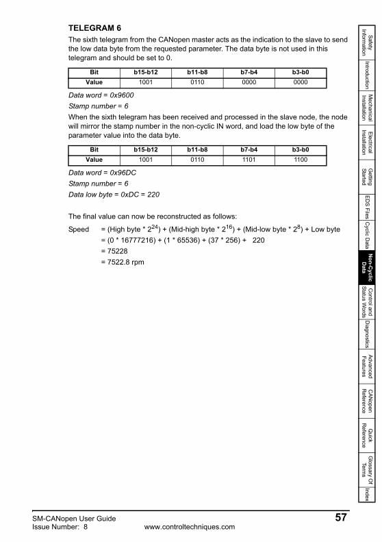
Safety Inform
ationIntroduction
Mechanical
InstallationElectrical
InstallationG
etting Started
EDS Files
Cyclic D
ataN
on-Cyclic
Data
Control and
Status Words
Diagnostics
Advanced Features
CAN
open R
eferenceQ
uick R
eferenceG
lossary Of
Terms
Index
TELEGRAM 6The sixth telegram from the CANopen master acts as the indication to the slave to send the low data byte from the requested parameter. The data byte is not used in this telegram and should be set to 0.
Data word = 0x9600Stamp number = 6When the sixth telegram has been received and processed in the slave node, the node will mirror the stamp number in the non-cyclic IN word, and load the low byte of the parameter value into the data byte.
Data word = 0x96DCStamp number = 6Data low byte = 0xDC = 220
The final value can now be reconstructed as follows:
Speed = (High byte * 224) + (Mid-high byte * 216) + (Mid-low byte * 28) + Low byte= (0 * 16777216) + (1 * 65536) + (37 * 256) + 220= 75228= 7522.8 rpm
Bit b15-b12 b11-b8 b7-b4 b3-b0Value 1001 0110 0000 0000
Bit b15-b12 b11-b8 b7-b4 b3-b0Value 1001 0110 1101 1100
SM-CANopen User Guide 57Issue Number: 8 www.controltechniques.com

8.2.5 Writing parameters using CT Single WordTo write to a 32-bit parameter using the non-cyclic channel, the following telegrams must be sent on each network cycle to construct the final message.
• Telegram 1 “Define menu number”.• Telegram 2 “Define parameter number”.• Telegram 3 “Send high data byte”.• Telegram 4 “Send mid-high data byte”.• Telegram 5 “Send mid-low data byte”.• Telegram 6 “Send low data byte”.
Figure 8-2 CT Single Word write sequence
The following example telegrams show how to set the digital speed reference 1 (Pr 1.21) to 12553.9 rpm (32-bit value is 125539) in the drive.
TELEGRAM 1The first telegram from the CANopen master indicates a WRITE cycle by setting the Read/Write bit to 0 and the stamp number to 1. The data byte contains the menu number for the parameter that is to be written to.
Data word = 0x1101Stamp number = 1Menu = 1When the first telegram has been received and processed in the slave node, it is mirrored in the non-cyclic IN word. This is the signal to the master controller program that the first telegram of the message has been received and the second telegram can be transmitted.
Bit b15-b12 b11-b8 b7-b4 b3-b0Value 0001 0001 0000 0001
Start
Send first telegramto OUT word 0
Read INword 0
Tx_Stamp_No =Rx_Stamp_No? Send next
telegram
Tx_Stamp_No= 6?
No
Yes
No
Yes
Check statusof ERR bit
1 ERRORCheck parameter
exists, and that it isa Read/Write
parameterParameterwritten OK
END OFSEQUENCE
WRITE
58 SM-CANopen User Guidewww.controltechniques.com Issue Number: 8
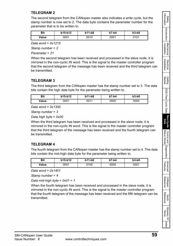
Safety Inform
ationIntroduction
Mechanical
InstallationElectrical
InstallationG
etting Started
EDS Files
Cyclic D
ataN
on-Cyclic
Data
Control and
Status Words
Diagnostics
Advanced Features
CAN
open R
eferenceQ
uick R
eferenceG
lossary Of
Terms
Index
TELEGRAM 2The second telegram from the CANopen master also indicates a write cycle, but the stamp number is now set to 2. The data byte contains the parameter number for the parameter that is to be written to.
Data word = 0x1215Stamp number = 2Parameter = 21When the second telegram has been received and processed in the slave node, it is mirrored in the non-cyclic IN word. This is the signal to the master controller program that the second telegram of the message has been received and the third telegram can be transmitted.
TELEGRAM 3The third telegram from the CANopen master has the stamp number set to 3. The data bits contain the high data byte for the parameter being written to.
Data word = 0x1300Stamp number = 3Data high byte = 0x00When the third telegram has been received and processed in the slave node, it is mirrored in the non-cyclic IN word. This is the signal to the master controller program that the third telegram of the message has been received and the fourth telegram can be transmitted.
TELEGRAM 4The fourth telegram from the CANopen master has the stamp number set to 4. The data bits contain the mid-high data byte for the parameter being written to.
Data word = 0x1401Stamp number = 4Data mid-high byte = 0x01 = 1When the fourth telegram has been received and processed in the slave node, it is mirrored in the non-cyclic IN word. This is the signal to the master controller program that the fourth telegram of the message has been received and the fifth telegram can be transmitted.
Bit b15-b12 b11-b8 b7-b4 b3-b0Value 0001 0010 0001 0101
Bit b15-b12 b11-b8 b7-b4 b3-b0Value 0001 0011 0000 0000
Bit b15-b12 b11-b8 b7-b4 b3-b0Value 0001 0100 0000 0001
SM-CANopen User Guide 59Issue Number: 8 www.controltechniques.com

TELEGRAM 5The fifth telegram from the CANopen master has the stamp number set to 5. The data bits contain the mid-low data byte for the parameter being written to.
Data word = 0x15EAStamp number = 5Data mid-low byte = 0xEA = 234When the fifth telegram has been received and processed in the slave node, it is mirrored in the non-cyclic IN word. This is the signal to the master controller program that the fifth telegram of the message has been received and the sixth telegram can be transmitted.
TELEGRAM 6The sixth telegram from the CANopen master has the stamp number set to 6. The data bits contain the low data byte for the parameter that is being written to.
Data word = 0x1663Stamp number = 6Data low byte = 0x63 = 99When the sixth telegram has been received and processed in the slave node, it will write the data (Pr 1.21 = 12553.9) as transmitted (the decimal point is automatically inserted when the data is transferred to the drive). If the operation is successful, the ERR bit is reset to 0 and the telegram is reflected in the non-cyclic IN word.
Data word = 0x1663Stamp number = 6Data low byte = 0x63 = 99If there was a problem with writing the data to the defined parameter, e.g. parameter is read only, does not exist, or data is out of range, the ERR bit is set to 1.
Bit b15-b12 b11-b8 b7-b4 b3-b0Value 0001 0101 1110 1010
Bit b15-b12 b11-b8 b7-b4 b3-b0Value 0001 0110 0110 0011
Bit b15-b12 b11-b8 b7-b4 b3-b0Value 0001 0110 0110 0011
60 SM-CANopen User Guidewww.controltechniques.com Issue Number: 8

Safety Inform
ationIntroduction
Mechanical
InstallationElectrical
InstallationG
etting Started
EDS Files
Cyclic D
ataN
on-Cyclic
Data
Control and
Status Words
Diagnostics
Advanced Features
CAN
open R
eferenceQ
uick R
eferenceG
lossary Of
Terms
Index
8.2.6 Abort CT Single Word non-cyclic messageThe internal state machine that controls the non-cyclic data transfer will only accept a new telegram if it contains the next expected telegram number (i.e. after accepting telegram 2, the state machine will only respond to telegram 3). If an error occurs in the master controller that causes the telegrams to get out of step, the master controller program must timeout, abort the message and reset the non-cyclic state machine.A Mode 1 non-cyclic message can be abandoned by resetting the state machine. This is done be setting the non-cyclic word to 0.
Data word = 0x0000Stamp number = 0
8.3 SM-CANopen set-up using non-cyclic dataThe SM-CANopen can also be configured using SDO or CT Single Word non-cyclic data. The configuration parameters for the slot in which the SM-CANopen is located can be accessed as Pr 60.xx.Changes made to the configuration parameters will not take effect until the SM-CANopen has been reset. The SM-CANopen can be reset by writing a value of 1 to Pr 60.32. A brief interruption in CANopen communications may be seen while the reset sequence is in progress. For information regarding data compression see section 11.8Cyclic data compression on page 80.
Bit b15-b12 b11-b8 b7-b4 b3-b0Value 0000 0000 0000 0000
All parameters must be stored after they are set, see section 5.14 Storing SM-CANopen configuration parameters on page 39 for more information.
NOTE
SM-CANopen User Guide 61Issue Number: 8 www.controltechniques.com

9 Control and Status Words
9.1 What are control and status words?The control and status words allow the digital control and monitoring of the drive to be implemented using a single data word for each function. Each bit in the control word has a particular function and provides a method of controlling the output functions of the drive, such as run and direction. These words can be accessed using either cyclic or non cyclic data.
Each bit in the status word provides feedback about the drives state of health and operational condition, such as drive healthy, drive at speed, etc.
9.2 Control word The SM-CANopen control word consists of 16 control bits some of which are reserved. See Table 9.1 for the individual bit function descriptions.
Table 9.1 Control word bit definitions
*not used on Commander SX
To enable fieldbus control the fieldbus enable signal (Pr 6.43) and the auto bit (bit7) must both be set to ‘1’. When the AUTO bit is reset to 0 the drive will revert to terminal control.
For safety reasons, the external HARDWARE ENABLE signal must be present before the fieldbus control word can be used to start the drive. This terminal is normally controlled by an external “Emergency Stop” circuit to ensure that the drive is disabled in an emergency situation.
The control word REMOTE bit directly controls the drive parameter Pr 1.42, the function of which is to select the digital speed reference as the source of the drives speed reference. When the REMOTE bit is reset to 0 the drive will revert to using the external analog speed reference.
The actual digital speed reference selected when REMOTE is set to 1 will be Pr 1.21, which is also the default mapping for the fieldbus speed reference. However Pr 1.15 can be used to change which of the digital references is selected. For further details on the drive digital speed references, please refer to the appropriate drive User Guide.
Table 9.2 lists in detail the function of each control word bit. For further in-depth details about drive control words and sequencing bits please refer to the appropriate drive User and Advanced User Guides.
b15 b14* b13 b12* b11 b10 b9* b8KEYPAD WDOG RESET TRIP JOG
REV REMOTE
b7* b6* b5 b4 b3 b2 b1 b0
AUTO NOT STOP RUN FWD
REVRUNREV
JOGFWD
RUNFWD ENABLE
See the Commander SX documentation for a description of these features with Commander SX as these may differ to Unidrive SP and Commander SK.
NOTE
62 SM-CANopen User Guidewww.controltechniques.com Issue Number: 8

Safety Inform
ationIntroduction
Mechanical
InstallationElectrical
InstallationG
etting Started
EDS Files
Cyclic D
ataN
on-Cyclic
Data
Control and
Status Words
Diagnostics
Advanced Features
CAN
open R
eferenceQ
uick R
eferenceG
lossary Of
Terms
Index
When a trip occurs, the drive control word MUST be set to a safe, disabled state. This ensures that the drive does not re-start unexpectedly when it is reset. This can be achieved by continuously monitoring the drive status word and interlocking it with the control word.
By default data compression is off and therefore the control word will be cast as 32 bit with bits 16-31 reserved.
Table 9.2 Control word bit functions
Bit Function Description
0 ENABLESet to 1 to enable the drive. Resetting to 0 will immediately disable the drive, and the motor will coast to a stop. The external HARDWARE ENABLE signal must also be present before the drive can be enabled.
1 RUN FWD Set to 1 (with ENABLE set to 1) to run the motor in the forward direction. When reset to 0, the drive will decelerate the motor to a controlled stop.
2* JOG FWDSet to 1 to jog the motor forward. This signal needs to be used in conjunction with the ENABLE bit. This signal is overridden by a RUN, RUN REV or RUN FWD signal.
3 RUN REV Set to 1 (with ENABLE set to 1) to run the motor in the reverse direction. When reset to 0, the drive will decelerate the motor to a controlled stop.
4 FWD REV Set to 1 to select the reverse direction. Set to 0 to run in the forward direction. The RUN signal is used to start and stop the motor.
5 RUNSet to 1 to run the motor. FWD REV is used to select the direction of motor rotation. When reset to 0, the drive will decelerate the motor to a controlled stop.
6* NOT STOP
Set to 1 to allow the sequencing bit in the drive to be latched. Refer to the drive Advanced User Guide for more details. If NOT STOP is zero, all latches are cleared and held at 0. Pr 6.04 must be correctly set for this to function.
7 AUTOSet to 1 to enable fieldbus control of the drive Control Word. The Control Word Enable (Pr 6.43) must also be set to 1. When reset to 0, the drive will operate under terminal control.
8 REMOTE
Set to 1 to select digital speed reference 1 (Pr 1.21), and to 0 to select analog reference 1 (Pr 1.36). REMOTE directly controls Pr 1.42, so reference selector (Pr 1.14) and preset selector (Pr 1.15) must both be set to 0 (default) for the REMOTE bit to work properly.
9* JOG REVSet to 1 to jog the motor in reverse. This signal needs to be used in conjunction with the ENABLE bit. This signal is overridden by a RUN/RUN REV/RUN FWD command.
10 Reserved -11 Reserved -
12 TRIPSet to 1 to trip the drive at any time. The trip display on drive will be “CL.bit” and the trip code will be 35. AUTO (b7) has no effect on this function. The trip cannot be cleared until TRIP is reset to 0.
NOTE
NOTE
SM-CANopen User Guide 63Issue Number: 8 www.controltechniques.com

*Unidrive SP only.
9.3 Status wordThe SM-CANopen status word consists of 16 control bits some of which are reserved. See the table below for the individual bit function descriptions.
The fieldbus status word is mapped directly from the drive status word, Pr 10.40.
Pr 10.40, is generated by the values of several individual drive status bits Table 9.3 shows the function indicated by each bit in the status word when set to 1.
13 RESET
A 0-1 transition of the RESET bit will reset the drive from a trip condition. If the reason for the trip is still present, or another fault condition has been detected, the drive will immediately trip again. When resetting the drive, it is recommended to check the status word to ensure that the reset was successful, before attempting to re-start the drive.
14* KEYPADWDOG
This watchdog is provided for an external keypad or other devices where a break in the communication link must be detected. The watchdog system can be enabled and/or serviced if this bit is changed from zero to one whilst the control word enabled.Once the watchdog is enabled it must be serviced at least once every second or an “SCL” trip will occur. The watchdog is disabled when an “SLC” trip occurs, and so it must be re-enabled when the trip is reset.
15 Reserved
Table 9.2 Control word bit functions
Bit Function Description
b15 b14 b13 b12 b11 b10 b9 b8Not
UsedMainsLoss
DirectionRunning
DirectionSet
BrakeAlarm
BrakeActive Regen Current
Limit
b7 b6 b5 b4 b3 b2 b1 b0Load
ReachedAbove Set
SpeedAt SetSpeed
Below SetSpeed
RunningAt Speed
ZeroSpeed
DriveActive
DriveHealthy
64 SM-CANopen User Guidewww.controltechniques.com Issue Number: 8

Safety Inform
ationIntroduction
Mechanical
InstallationElectrical
InstallationG
etting Started
EDS Files
Cyclic D
ataN
on-Cyclic
Data
Control and
Status Words
Diagnostics
Advanced Features
CAN
open R
eferenceQ
uick R
eferenceG
lossary Of
Terms
Index
Table 9.3 Drive status word bit functions
Bit Function Parameter Description0 Drive healthy Pr 10.01 Indicates the drive is not in the trip state. 1 Drive active Pr 10.02 Indicates that the output stage of the drive is active.
2 Zero speed Pr 10.03
In Open Loop mode, zero speed indicates that the absolute value of the post-ramp speed reference is at or below the zero speed threshold.Unidrive SP only - In Closed Loop and Servo modes, zero speed indicates that the absolute value of speed feedback is at or below the zero speed threshold.
3
Running at or below
minimum speed
Pr 10.04
In bipolar mode (Pr 1.10 = 1) Pr 10.04 is the same as zero speed, Pr 10.03. (See above.)In unipolar mode, Pr 10.04 is set if the absolute value of the post-ramp speed reference (Pr 2.01) or speed feedback (Pr 3.02) is at or below minimum speed + 0.5Hz or 5rpm. (Minimum speed is defined by Pr 1.07.) This parameter is only set if the drive is running.
4 Below set speed Pr 10.05
Only set if the drive is running at below set speed. Refer to Pr 3.06, Pr 3.07 and Pr 3.09 in the drive User Guide for more details.
5 At speed Pr 10.06 Only set if the drive is running at set speed. Refer to Pr 3.06, Pr 3.07 and Pr 3.09 in the drive User Guide.
6 Above set speed Pr 10.07
Only set if the drive is running at above set speed. Refer to Pr 3.06, Pr 3.07 and Pr 3.09 in the drive User Guide for more details.
7 Load reached Pr 10.08Indicates that the modulus of the active current is greater or equal to the rated active current, as defined in menu 4. Refer to the drive Advanced User Guide for more details.
8 In current limit Pr 10.09 Indicates that the current limits are active.
9 Regenerating Pr 10.10Unidrive SP Only: regenerating indicates that power is being transferred from the motor to the drive.In regen mode, regenerating indicates that power is being transferred from the Unidrive SP to the supply.
10 Dynamic brake active Pr 10.11
Indicates that the braking IGBT is active. If the IGBT becomes active, this parameter will remain on for at least one second.
11 Dynamic brake alarm Pr 10.12
Dynamic brake alarm is set when the braking IGBT is active, and the braking energy accumulator is greater than 75%.
12 Direction commanded Pr 10.13
Direction commanded is set to 1 if the Pre-ramp speed reference (Pr 1.03) is negative and reset to 0 if the Pre-ramp speed reference is zero or positive.
13 Direction running Pr 10.14
A 0 indicates forward direction and a 1 indicates reverse direction. The source of this bit is Pr 2.01 for open loop mode and Pr 3.02 for closed loop and servo modes.
14 Mains loss Pr 10.15
Mains loss indicates that the drive has detected a mains loss from the level of the DC bus voltage. This parameter can only become active if mains loss ride through or mains loss stop modes are selected. Refer to Pr 6.03 in the drive Advanced User Guide for more details.Unidrive SP only - In regen mode, mains loss is the inverse of Pr 3.07. Refer to the Unidrive SP Advanced User Guide for more details.
15 Not Used Reserved.
SM-CANopen User Guide 65Issue Number: 8 www.controltechniques.com

10 DiagnosticsThis section provides basic diagnostic information intended to enable the resolution of the most common problems encountered when setting up SM-CANopen on a network. A high percentage of problems reported are basic set-up problems that can be avoided. Start by using the flow chart (Figure 10-1) to determine the possible cause of a problem. If after following the flow chart you are still experiencing problems please contact your supplier or local drive centre for support.Before requesting support please ensure that you have read the following section and have recorded the firmware/system file versions for SM-CANopen, the drive and SM-Applications where applicable, see Chapter 5 Getting Started on page 21 for more information on configuration.
Figure 10-1 Diagnostic flow chartSTART
CHECK CABLING,TERMINATION,
ADDRESSING ANDBAUDRATE
CHECK NUMBER OFNODES PER SEGMENT
CHECK CONFIGURATIONIN GETTING STARTED
FLOWCHARTS
CHECK PARAMETERS INQUICK REFERENCE
ARE YOU USING SDOCONFIGURATION?
NO YES
IF NON DEFAULT PDONUMBERS ARE USED0x2800 & 0x2801 ARE
REQUIRED
CHECK ERROR CODESFROM SDOs
CHECKPr MM.10 - Pr MM.13 ANDPr MM.20 - Pr MM.23 ARE
CORRECTLY MAPPED
CHECK Pr MM.41
ONLY PDOS 1, 3, 5 & 6AVAILABLE
CHECK MAPPINGS ANDSIZES
CHECK THAT A SAVE ISPERFORMED FOR THE
COMMUNICATION OBJECTS(OBJECT 0x1010)
CHECKPr MM.49 AND Pr MM.50
CHECK Pr MM.06
ENDNOTE: MOST INSTALLATION ISSUES ARE DUE TO
INCORRECT SETUP OR CABLING ISSUES
ENSURE MODULE ISRESET AND A DRIVE SAVE
IS PERFORMED
CHECK Pr MM.05 or(Pr MM.39 AND Pr MM.40)
66 SM-CANopen User Guidewww.controltechniques.com Issue Number: 8

Safety Inform
ationIntroduction
Mechanical
InstallationElectrical
InstallationG
etting Started
EDS Files
Cyclic D
ataN
on-Cyclic
Data
Control and
Status Words
Diagnostics
Advanced Features
CAN
open R
eferenceQ
uick R
eferenceG
lossary Of
Terms
Index
10.1 Module ID code
The module ID code indicates the type of Solutions Module that is fitted in the corresponding slot, this should be checked to ensure the correct module is fitted.
10.2 SM-CANopen firmware version
The full version of the SM-CANopen firmware can be read for the corresponding slot. Table 10.1 shows how to construct the full firmware version from these values. This version number will be required for technical support.
10.3 SM-CANopen node address
Every node on a CANopen network must be given a unique network node address. If two or more nodes are assigned the same node address, network errors may result as 2 nodes attempt to transmit at the same time. The valid range for the node address is 1 to 127, with a default address of 0. The SM-CANopen must be reset to make a change of node address take effect, see section 5.12 Resetting the SM-CANopen (re-initialising) on page 39.If an invalid node address is set SM-CANopen will over-write the value in Pr MM.03 with 0. When the SM-CANopen is reset the value in this parameter will be used as the CANopen node address.
SM-CANopen Module ID code
Pr MM.01Default N/ARange 408Access RO
SM-CANopen firmware - major version
Pr MM.02Default N/ARange 00.00 to 99.99Access RO
SM-CANopen firmware - minor version
Pr MM.51Default N/ARange 0 to 99Access RO
Table 10.1 SM-CANopen firmware version
Major version
Minor version Firmware version
03.01 0 V03.01.00
SM-CANopen node address
Pr MM.03Default 0Range 0 to 127Access RW
A node address of 0 will disable the DS301 CANopen communications layer, however the DSP305 V1.1 Layer Setting Service (LSS) will still be active.
NOTE
SM-CANopen User Guide 67Issue Number: 8 www.controltechniques.com

10.4 SM-CANopen data rate
Every node on a CANopen network must be configured to run at the same network data rate. If a node is configured with the wrong data rate, it may cause errors on the CAN network, and eventually trip on “SLx.Er” with error code of 66. The SM-CANopen must be reset to make a change of data rate take effect (see section 5.12 Resetting the SM-CANopen (re-initialising) on page 39).If an invalid data rate is set, the SM-CANopen will reject the configured data rate and revert to the nearest valid setting. The default data rate is 500Kbits/s.
SM-CANopen can automatically detect the network data rate by setting Pr MM.04 to -1. The SM-CANopen will monitor the CAN network and if the data rate is detected, it will set Pr MM.04 to indicate the detected data rate. However, it should be noted that the new value of Pr MM.04 will NOT be stored (this would require a drive save).
10.5 SM-CANopen operating status
The CANopen network activity can be monitored in the SM-CANopen operating status parameter, Pr MM.06. When the SM-CANopen is communicating successfully with the CANopen master controller, the SM-CANopen operating status will give an indication of the number of data messages per second that are being processed.
SM-CANopen data rate
Pr MM.04Default 2Range -1 to 8Access RW
Table 10.2 SM-CANopen data rates
Pr MM.04 bits/s Pr MM.04 bits/s-1 Auto 4 125K0 1.0M 5 100K1 800K 6 50K2 500K 7 20K3 250K 8 10K
The SM-CANopen may have problems detecting the network data rate if there is little traffic on the CANopen network. Auto-detection of the data rate is ideal when connecting a new node to an existing network, but may not work reliably if a network is powered up with all nodes attempting to detect the network data rate.
NOTE
CANopen operating status
Pr MM.06Default N/ARange -10 to 9999Access RO
In version 03.01.00 and earlier Pr MM.06 includes all received PDOs, SYNC messages and all transmitted PDOs. The network loss trip (as defined by Pr MM.07) will occur if non of the above events occurs within the specified time period. This scheme means that if a TxPDO is configured to transmit on a timer or an event, a network loss trip will not occur even if the network cable is removed.
NOTE
68 SM-CANopen User Guidewww.controltechniques.com Issue Number: 8

Safety Inform
ationIntroduction
Mechanical
InstallationElectrical
InstallationG
etting Started
EDS Files
Cyclic D
ataN
on-Cyclic
Data
Control and
Status Words
Diagnostics
Advanced Features
CAN
open R
eferenceQ
uick R
eferenceG
lossary Of
Terms
Index
If a configuration or network error is detected, the drive may trip. This prevents transmitted PDOs from timer or event transactions, preventing a network loss trip asdefined in Pr MM.07.
10.6 SM-CANopen mapping status
If the SM-CANopen operating status parameter (Pr MM.06) indicates “-3”, a mapping configuration error has been detected. The reason for the error is indicated by the SM-CANopen mapping status parameter (Pr MM.49). When a mapping error has been corrected, reset SM-CANopen by setting Pr MM.32 to ON (this will revert immediately to 0).
In version 03.01.01 and later Pr MM.06 includes all received PDOs, SYNC messages and all transmitted messages of any type. The network loss trip (as defined by Pr MM.07) will occur if no data is received within the specified time period. This scheme means that even if a TxPDO is configured to transmit on a timer or an event, a network loss trip will occur even if the network cable is removed.
Table 10.3
Pr MM.06 Parameter Description>0 Network healthy Indicates the number of successful network cycles per second.
0 Network healthy, no data transfer
Indicates that the CANopen master has established communica-tions with SM-CANopen, but there is currently no data transfer in progress.
-1 Initialised Indicates that SM-CANopen has initialised correctly and is waiting for the CANopen master to initialise communications.
-2 Internal hardware failure
Indicates that part of the SM-CANopen initialisation sequence was not successful. If this fault persists after a power cycle, replace the SM-CANopen.
-3 Configuration error
Indicates that there is an invalid setting in the SM-CANopen con-figuration parameters see section 10.6SM-CANopen mapping status on page 69 and section 10.7SM-CANopen error code on page 72 for further diagnostic details.
-4 Unrecoverable software error
An internal software error has occurred. Reset the SM-CANopen to clear, if error persists, replace the SM-CANopen.
-8Data rate
detection in progress
The SM-CANopen is currently attempting to detect the CANopen network data rate.
-10 Device disabled Indicates that the DS301 V1.1 CANopen communications layer has been disabled by setting the node address to 0.
NOTE
SM-CANopen mapping status
Pr MM.49Default 0Range 0 to 255Access RO
SM-CANopen User Guide 69Issue Number: 8 www.controltechniques.com
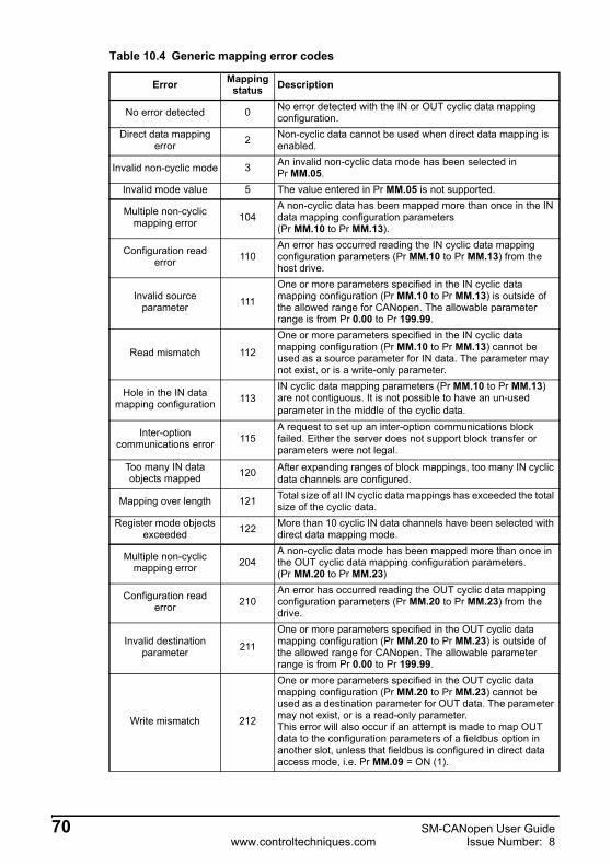
Table 10.4 Generic mapping error codes
Error Mapping status Description
No error detected 0 No error detected with the IN or OUT cyclic data mapping configuration.
Direct data mapping error 2 Non-cyclic data cannot be used when direct data mapping is
enabled.
Invalid non-cyclic mode 3 An invalid non-cyclic data mode has been selected in Pr MM.05.
Invalid mode value 5 The value entered in Pr MM.05 is not supported.
Multiple non-cyclic mapping error 104
A non-cyclic data has been mapped more than once in the IN data mapping configuration parameters(Pr MM.10 to Pr MM.13).
Configuration read error 110
An error has occurred reading the IN cyclic data mapping configuration parameters (Pr MM.10 to Pr MM.13) from the host drive.
Invalid source parameter 111
One or more parameters specified in the IN cyclic data mapping configuration (Pr MM.10 to Pr MM.13) is outside of the allowed range for CANopen. The allowable parameter range is from Pr 0.00 to Pr 199.99.
Read mismatch 112
One or more parameters specified in the IN cyclic data mapping configuration (Pr MM.10 to Pr MM.13) cannot be used as a source parameter for IN data. The parameter may not exist, or is a write-only parameter.
Hole in the IN data mapping configuration 113
IN cyclic data mapping parameters (Pr MM.10 to Pr MM.13) are not contiguous. It is not possible to have an un-used parameter in the middle of the cyclic data.
Inter-option communications error 115
A request to set up an inter-option communications block failed. Either the server does not support block transfer or parameters were not legal.
Too many IN data objects mapped 120 After expanding ranges of block mappings, too many IN cyclic
data channels are configured.
Mapping over length 121 Total size of all IN cyclic data mappings has exceeded the total size of the cyclic data.
Register mode objects exceeded 122 More than 10 cyclic IN data channels have been selected with
direct data mapping mode.
Multiple non-cyclic mapping error 204
A non-cyclic data mode has been mapped more than once in the OUT cyclic data mapping configuration parameters. (Pr MM.20 to Pr MM.23)
Configuration read error 210
An error has occurred reading the OUT cyclic data mapping configuration parameters (Pr MM.20 to Pr MM.23) from the drive.
Invalid destination parameter 211
One or more parameters specified in the OUT cyclic data mapping configuration (Pr MM.20 to Pr MM.23) is outside of the allowed range for CANopen. The allowable parameter range is from Pr 0.00 to Pr 199.99.
Write mismatch 212
One or more parameters specified in the OUT cyclic data mapping configuration (Pr MM.20 to Pr MM.23) cannot be used as a destination parameter for OUT data. The parameter may not exist, or is a read-only parameter.This error will also occur if an attempt is made to map OUT data to the configuration parameters of a fieldbus option in another slot, unless that fieldbus is configured in direct data access mode, i.e. Pr MM.09 = ON (1).
70 SM-CANopen User Guidewww.controltechniques.com Issue Number: 8
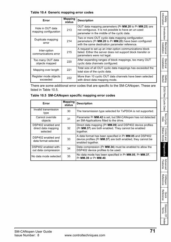
Safety Inform
ationIntroduction
Mechanical
InstallationElectrical
InstallationG
etting Started
EDS Files
Cyclic D
ataN
on-Cyclic
Data
Control and
Status Words
Diagnostics
Advanced Features
CAN
open R
eferenceQ
uick R
eferenceG
lossary Of
Terms
Index
There are some additional error codes that are specific to the SM-CANopen. These are listed in Table 10.5.
Hole in OUT data mapping configuration 213
OUT data mapping parameters (Pr MM.20 to Pr MM.23) are not contiguous. It is not possible to have an un-used parameter in the middle of the cyclic data.
Duplicate mapping error 214
Two or more OUT cyclic data mapping configuration parameters (Pr MM.20 to Pr MM.23) have been configured with the same destination parameter reference.
Inter-option communications error 215
A request to set up an inter-option communications block failed. Either the server does not support block transfer or parameters were not legal.
Too many OUT data objects mapped 220 After expanding ranges of block mappings, too many OUT
cyclic data channels configured.
Mapping over length 221 Total size of all OUT cyclic data mappings has exceeded the total size of the cyclic data.
Register mode objects exceeded 222 More than 10 cyclic OUT data channels have been selected
with direct data mapping mode.
Table 10.5 SM-CANopen specific mapping error codes
Error Mapping status Description
Invalid transmission type 30 The transmission type selected for TxPDOA is not supported.
Cannot override objects 31 Parameter Pr MM.42 is set, but SM-CANopen has not detected
an SM-Applications fitted to the drive.DSP402 enabled and direct data mapping
selected32
Direct data mapping (Pr MM.09) and DSP402 device profiles (Pr MM.37) are both enabled. They cannot be enabled together.
DSP402 enabled and data format selected 33
A data format has been specified in Pr MM.05 and DSP402 device profiles (Pr MM.37) are both enabled, they cannot be enabled together.
DSP402 enabled with-out data compression 34 Data compression (Pr MM.34) must be enabled to allow the
DSP402 device profiles to be used.
No data mode selected 35 No data mode has been specified in Pr MM.05, Pr MM.37, Pr MM.39 or Pr MM.40.
Table 10.4 Generic mapping error codes
Error Mapping status Description
SM-CANopen User Guide 71Issue Number: 8 www.controltechniques.com
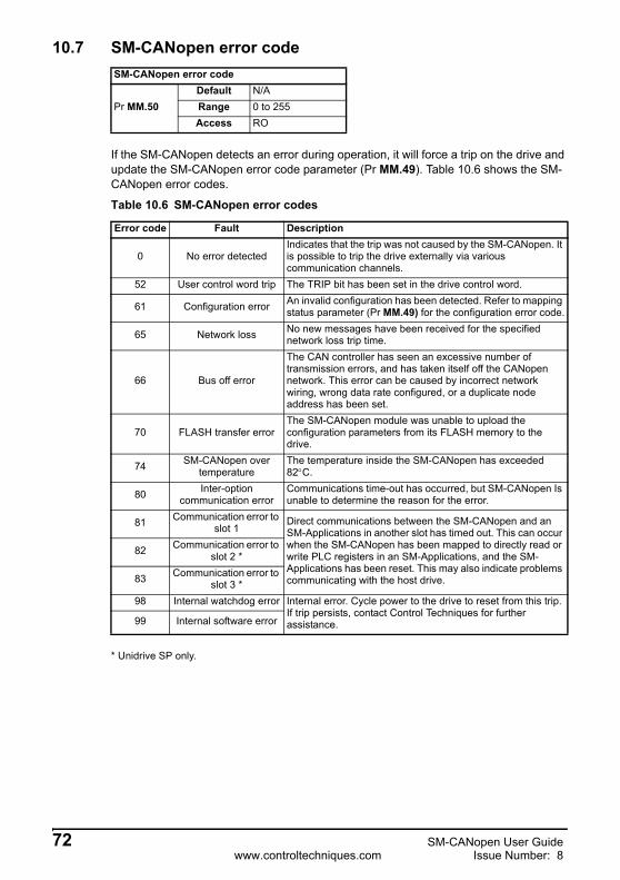
10.7 SM-CANopen error code
If the SM-CANopen detects an error during operation, it will force a trip on the drive and update the SM-CANopen error code parameter (Pr MM.49). Table 10.6 shows the SM-CANopen error codes.
* Unidrive SP only.
SM-CANopen error code
Pr MM.50Default N/ARange 0 to 255Access RO
Table 10.6 SM-CANopen error codes
Error code Fault Description
0 No error detectedIndicates that the trip was not caused by the SM-CANopen. It is possible to trip the drive externally via various communication channels.
52 User control word trip The TRIP bit has been set in the drive control word.
61 Configuration error An invalid configuration has been detected. Refer to mapping status parameter (Pr MM.49) for the configuration error code.
65 Network loss No new messages have been received for the specified network loss trip time.
66 Bus off error
The CAN controller has seen an excessive number of transmission errors, and has taken itself off the CANopen network. This error can be caused by incorrect network wiring, wrong data rate configured, or a duplicate node address has been set.
70 FLASH transfer errorThe SM-CANopen module was unable to upload the configuration parameters from its FLASH memory to the drive.
74 SM-CANopen over temperature
The temperature inside the SM-CANopen has exceeded 82°C.
80 Inter-option communication error
Communications time-out has occurred, but SM-CANopen Is unable to determine the reason for the error.
81 Communication error to slot 1
Direct communications between the SM-CANopen and an SM-Applications in another slot has timed out. This can occur when the SM-CANopen has been mapped to directly read or write PLC registers in an SM-Applications, and the SM-Applications has been reset. This may also indicate problems communicating with the host drive.
82 Communication error to slot 2 *
83 Communication error to slot 3 *
98 Internal watchdog error Internal error. Cycle power to the drive to reset from this trip. If trip persists, contact Control Techniques for further assistance.99 Internal software error
72 SM-CANopen User Guidewww.controltechniques.com Issue Number: 8

Safety Inform
ationIntroduction
Mechanical
InstallationElectrical
InstallationG
etting Started
EDS Files
Cyclic D
ataN
on-Cyclic
Data
Control and
Status Words
Diagnostics
Advanced Features
CAN
open R
eferenceQ
uick R
eferenceG
lossary Of
Terms
Index
10.8 Stuff BitsStuff bits are used by CANopen to ensure that each CANopen device does not transmit a long stream of consecutive 1s or 0s. The number of stuff bits in a CANopen frame depends mainly on the values in the data bytes of the CANopen frame (a series of bytes with 0x00 or 0xFF will produce most stuff bits). The maximum recommended load factor of 0.85 accounts for the worst case number of CANopen stuff bits that may be transmitted in a single frame.If stuff bits have already been accounted for in the number of bits for each PDO, the network load factor must be < 1.0 for the network to work reliably.Remember the stuff bit will make values appear to be incorrect when looking at the network with an oscilloscope.
NOTE
SM-CANopen User Guide 73Issue Number: 8 www.controltechniques.com
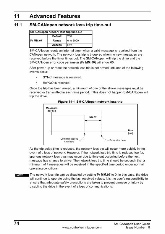
11 Advanced Features11.1 SM-CANopen network loss trip time-out
SM-CANopen resets an internal timer when a valid message is received from the CANopen network. The network loss trip is triggered when no new messages are received before the timer times out. The SM-CANopen will trip the drive and the SM-CANopen error code parameter (Pr MM.50) will show 65.
After power-up or reset the network loss trip is not armed until one of the following events occur:
• SYNC message is received.
• RxPDO is received.
Once the trip has been armed, a minimum of one of the above messages must be received or transmitted in each time period. If this does not happen SM-CANopen will trip the drive.
Figure 11-1 SM-CANopen network loss trip
As the trip delay time is reduced, the network loss trip will occur more quickly in the event of a loss of network. However, if the network loss trip time is reduced too far, spurious network loss trips may occur due to time-out occurring before the next message has chance to arrive. The network loss trip time should be set such that a minimum of 4 messages will be received in the specified time period under normal operating conditions.
SM-CANopen network loss trip time-out
Pr MM.07Default 200Range 0 to 3000Access RW
The network loss trip can be disabled by setting Pr MM.07 to 0. In this case, the drive will continue to operate using the last received values. It is the user’s responsibility to ensure that adequate safety precautions are taken to prevent damage or injury by disabling the drive in the event of a loss of communications.
Communicationsstop here Drive trips here
Time(ms)
Messagesper sec
MM.07
NOTE
74 SM-CANopen User Guidewww.controltechniques.com Issue Number: 8

Safety Inform
ationIntroduction
Mechanical
InstallationElectrical
InstallationG
etting Started
EDS Files
Cyclic D
ataN
on-Cyclic
Data
Control and
Status Words
Diagnostics
Advanced
FeaturesC
ANopen
Reference
Quick
Reference
Glossary O
f Term
sIndex
11.2 SM-CANopen data endian format
When data is sent over the CANopen network, it is transmitted as 8-bit bytes. This means, when a 32-bit double word or 16-bit word data value is split into four or two 8-bit bytes, it is important that the receiving node reconstructs the received bytes correctly to arrive at the 32-bit or 16-bit data value that was originally transmitted. The order in which 8-bit bytes are transmitted is known as the “data endian format”. For CANopen, the endian format is specified as “little endian”.
11.3 Unidrive SP: inter-option communication timingWhen more than one Solutions Module is fitted to a Unidrive-SP, communications between modules uses inter-option communications. Inter-option communications is slower than communication directly to the drive parameters.
Typical access times for direct menu access to the drive menu will be in the region of 30μs (per parameter), a similar access using inter-option communications will be in the region of 1ms (per parameter).
When using inter-option communications, if parameters are sequential (within the same menu) then up to 5 parameters may be grouped in to a block, (although this is limited to 4 by the PDO size) this will take up to 1ms for this block to be transferred. A maximum of 8 blocks for input and 8 blocks for output are available.
In version (03.01.00) or earlier, the following applies. Pr MM.06 includes all received PDOs and SYNC messages and all transmitted PDO messages. The network loss trip occurs if no SYNC or PDOs are received and no PDOs transmitted within the trip time period (Pr MM.07). Please refer to section 11.1 SM-CANopen network loss trip time-out on page 74 for further details on Pr MM.07.In version (03.01.01) and later the following applies. Pr MM.06 includes all received PDOs and SYNC messages and ALL transmitted messages of ANY type. The network loss trip will occur if no SYNC or PDOs are received within the trip time period. ALL transmitted messages will be ignored. Please refer to section 10.5 SM-CANopen operating status on page 68 for further detail on Pr MM.06.
NOTE
SM-CANopen Data endian format
Pr MM.08Default ON (little)Range N/AAccess RO
Table 11.1 Data endian format
Data endian format
Pr MM.0816-bit value 32-bit value
Byte order Word order Byte order
Little 1 Low byte firstHigh byte second
Low word firstHigh word second
Low byte firstMid low byte secondMid high byte thirdHigh byte fourth
SM-CANopen User Guide 75Issue Number: 8 www.controltechniques.com

11.4 Local Solutions Module parameter accessThe menu used to configure the SM-CANopen depends on the slot in the Unidrive SP where SM-CANopen is fitted. Menu 60 can be used to ensure that the CANopen configuration parameters can be accessed without necessarily knowing in which drive slot the SM-CANopen is fitted, this can also be used for Commander SK/SX.
When a Menu 60 parameter is accessed from CANopen, the SM-CANopen will re-direct it to the menu that is associated with the slot where the SM-CANopen is fitted.
11.5 Unidrive SP: mapping To SM-Applications parametersSM-CANopen can read and write data directly to and from internal registers in SM-Applications. Six sets of 32-bit registers are accessible in SM-Applications (additional information is available in section 11.6 Unidrive SP: block mapping on page 77), each register in SM-Applications can be accessed as a virtual parameter.
SM-CANopen can be configured to read data from and write data to an SM-Applications fitted in any slot in the Unidrive SP by specifying the target parameter as shown in Table 11.2.
If the SM-CANopen is configured to map data to Pr 70.xx and Pr 91.xx parameters, data will be exchanged with the SM-Applications fitted in the lowest slot number. This method is convenient to use if there is only one SM-Applications fitted to the Unidrive SP, as it guarantees that data will always be written to the SM-Applications, even if it is moved to a different slot. If two SM-Applications are fitted, it is best to map directly to the required slot.
Table 11.2 SM-Applications internal parameters
SM-Applications parameters Parameter reference
Direct to slot 1
Direct to slot 2
Direct to slot 3
_Pxx% PLC Registers Pr 70.xx Pr 100.xx Pr 130.xx Pr 160.xx_Qxx% PLC Registers Pr 71.xx Pr 101.xx Pr 131.xx Pr 161.xx_Rxx% PLC Registers Pr 72.xx Pr 102.xx Pr 132.xx Pr 162.xx_Sxx% PLC Registers Pr 73.xx Pr 103.xx Pr 133.xx Pr 163.xx_Txx% PLC Registers Pr 74.xx Pr 104.xx Pr 134.xx Pr 164.xx_Uxx% PLC Registers Pr 75.xx Pr 105.xx Pr 135.xx Pr 165.xx
Local Configuration Parameters Pr 81.xx Pr 111.xx Pr 141.xx Pr 171.xxTimer Function Parameters Pr 85.xx Pr 115.xx Pr 145.xx Pr 175.xx
Digital I/O Parameters Pr 86.xx Pr 116.xx Pr 146.xx Pr 176.xxStatus Parameters Pr 88.xx Pr 118.xx Pr 148.xx Pr 178.xx
General Parameters Pr 90.xx Pr 120.xx Pr 150.xx Pr 180.xxFast Access Parameters Pr 91.xx Pr 121.xx Pr 151.xx Pr 181.xx
76 SM-CANopen User Guidewww.controltechniques.com Issue Number: 8

Safety Inform
ationIntroduction
Mechanical
InstallationElectrical
InstallationG
etting Started
EDS Files
Cyclic D
ataN
on-Cyclic
Data
Control and
Status Words
Diagnostics
Advanced
FeaturesC
ANopen
Reference
Quick
Reference
Glossary O
f Term
sIndex
11.5.1 Unidrive SP: single SM-Applications fittedConsider a Unidrive SP with the following configuration:
• Slot 1 - Vacant
• Slot 2 - SM-Applications.
• Slot 3 - SM-CANopen.
If a parameter read request comes over CANopen to read Pr 71.08, this will be re-directed to the SM-Applications in the lowest slot number, i.e. the SM-Applications in slot 2. The value in _Q08% from slot 2 will be returned.
If a parameter read request comes over CANopen to read Pr 131.08, this will be sent straight to the SM-Applications in slot 2. The value in _Q08% from slot 2 will be returned.
If a parameter read request comes over CANopen to read Pr 101.08, this will be sent straight to the SM-Applications in slot 1. As there is no SM-Applications fitted in slot 1, an error message will be returned, indicating that the parameter does not exist.
11.5.2 Unidrive SP: dual SM-Applications fittedConsider a Unidrive SP with the following configuration:
• Slot 1 - SM-Applications.
• Slot 2 - SM-Applications.
• Slot 3 - SM-CANopen.
If a parameter read request comes over CANopen to read Pr 71.08, this will be re-directed to the SM-Applications in the lowest slot number, i.e. the SM-Applications in slot 1. The value in _Q08% from slot 1 will be returned.
If a parameter read request comes over CANopen to read Pr 131.08, this will be sent straight to the SM-Applications in slot 2. The value in _Q08% from slot 2 will be returned.
If a parameter read request comes over CANopen to read Pr 101.08, this will be sent straight to the SM-Applications in slot 1. The value in _Q08% from slot 1 will be returned.
11.6 Unidrive SP: block mappingOn SM-CANopen there are 4 used mapping parameters available for both input (4) and output mappings(4). Block mapping is configured by placing ascending parameters (within the same menu) in to consecutive mapping parameters. Consider the example in Table 11.3.
If a single SM-Applications is fitted to the Unidrive SP, normal SM-Applications parameter references can be used without problem, as the SM-CANopen will automatically divert them to the SM-Applications.
If two SM-Applications are fitted to the Unidrive SP, it is best to access SM-Applications parameters using the direct slot parameter references. If normal SM-Applications parameter references are used, and the SM-Applications is removed from slot 1, these parameter references will be re-directed to slot 2 instead.
NOTE
Block mapping is only available when using Pr 18.xx, Pr 19.xx, Pr 20.xx and on the PLC registers within SM-Applications. Commander SX does not support this feature.
NOTE
SM-CANopen User Guide 77Issue Number: 8 www.controltechniques.com

Table 11.3 Block Mapping Example
This will map parameters Pr 18.11 to Pr 18.12 and Pr 18.13 to Pr 18.14 giving a total of 8 mappings, using only 4 of the mapping parameters as shown in Table 11-2.
Figure 11-2 Block Mapping Expansions
Block mapping can also be used when mapping data to the PLC registers in SM-Applications. If it is required to map to individual parameters within the same menu ensure that the target registers are listed in descending order (see section 11.6.1 Avoiding block mapping ).
Mapping parameter Mapping value Description
Pr MM.10 1811 Map to 1811 as the start for the block mapping.Pr MM.11 1814 Map to 1814 as the end for the block mapping.Pr MM.20 1815 Map to 1815 as the start for the block mapping.Pr MM.21 1818 Map to 1818 as the end for the block mapping.
1811181218131814
18141811
18181815
1815181618171818
Input Mappings(mm.10 - mm.13)
Output Mappings(mm.20 - mm.23)
mappingsexpanded
mappingsexpanded
TxPDO
RxPDO
78 SM-CANopen User Guidewww.controltechniques.com Issue Number: 8

Safety Inform
ationIntroduction
Mechanical
InstallationElectrical
InstallationG
etting Started
EDS Files
Cyclic D
ataN
on-Cyclic
Data
Control and
Status Words
Diagnostics
Advanced
FeaturesC
ANopen
Reference
Quick
Reference
Glossary O
f Term
sIndex
11.6.1 Avoiding block mappingIn the above section block mapping was used to define mapping ranges. In order to avoid this the target parameters should be entered in descending order. This means that SM-CANopen will not recognise a range of parameters and only 2 parameters will be mapped.
11.7 Direct data mapping
By default, Pr MM.10 to Pr MM.13 and Pr MM.20 to Pr MM.23 are used as pointers to specify the destination parameter for OUT data received from the master controller, and the source parameter of IN data to be transmitted to the master controller, for PDOA.
When direct data mapping is enabled, Pr MM.10 to Pr MM.13 and Pr MM.20 to Pr MM.23 are used as the actual destination and source parameters for OUT data and IN data respectively.
When direct data mapping mode is enabled all mapping parameters (Pr MM.10 to Pr MM.13 and Pr MM.20 to Pr MM.23) will be reset to 0. When data compression is OFF, the number of data words specified in Pr MM.05 must be an even number. If an odd number is specified the appropriate parameter will be set to specify the next lowest even number of data words, (i.e. a value of 7 in Pr MM.05 will only handle 6 data words or 3 data channels).
Table 11.4 Non-block data mapping example
Mapping parameter
Mapping value Description
Pr MM.10 2004 Map to Pr 20.04.Pr MM.11 2001 Map to Pr 20.01.
Pr MM.12 to Pr MM.13 0 Not mapped
Pr MM.20 2035 Map to Pr 20.35 Pr MM.21 2031 Map to Pr 20.31
Pr MM.22 to Pr MM.23 0 Not mapped
SM-CANopen Direct data mapping enable
Pr MM.09Default OFF (0)Range OFF (0) or ON (1)Access RW
CT Single Word and PPO 4 Word non-cyclic data modes cannot be used when direct mapping is enabled.
Table 11.5 Direct data mapping configurations (data compression OFF)Pr MM.05 Description
2 to 4The 2 channels on RxPDOA will be written directly to Pr MM.10 and Pr MM.11, and the 2 channels on TxPDOA will be read directly from Pr MM.20 to Pr MM.21.
NOTE
SM-CANopen User Guide 79Issue Number: 8 www.controltechniques.com

Parameters Pr MM.10 to Pr MM.13 and Pr MM.20 to Pr MM.23 are all 16-bit parameters, so each data channel will be reduced to 16-bits when data compression is enabled. Hence, a maximum of 4 channels can be created when using direct data mapping.
11.8 Cyclic data compression
By default SM-CANopen uses 32-bits (i.e. 2 data words, for each data channel) even if the target source parameter in the drive is a 16-bit parameter. This strategy ensures that the cyclic data transmitted over the CANopen network is kept aligned with memory locations in new 32-bit PLCs.
Table 11.7 shows an example set of mapping parameters where 2 IN and 2 OUT cyclic data channels are required for RxPDOA and TxPDOA. With data compression disabled, each data channel uses 32-bits (i.e. 2 data words, so a total of 6 words are required). This is not possible for the SM-CANopen as this exceeds the size of the PDO.
When data compression is enabled by setting Pr MM.34 = ON, a data channel will only use 32 bits if the target drive parameter is a 32 bit parameter. If the target drive parameter for a data channel is only 1, 8 or 16 bits wide, only 16 bits will be used for that particular data channel. Hence, the IN and OUT data will now only use a total of 3 words, so Pr MM.05 can now be set to 3 and the data format can be handled by RxPDOA and TxPDOA. This also applies to mappings performed over SDO.
11.9 Unidrive SP: event task trigger in SM-Applications
Table 11.6 Direct data mapping configurations (data compression ON)
Pr MM.05 Description
1 to 8 The 4 channels on RxPDOA will be written directly to Pr MM.10 to Pr MM.13, and the 4 channels on RxPDOA will be read directly from Pr MM.20 to Pr MM.23.
SM-CANopen Cyclic data compression enable
Pr MM.34Default OFF (0)Range OFF (0) or ON (1)Access RW
Table 11.7 Example cyclic data channel mapping
Data channel Data words used
Mapping for slot Setting Data
width Mapping status
IN channel 0 IN word 0, 1 Pr MM.10 1040 16-bit Pr 10.40, status wordIN channel 1 IN word 2, 3 Pr MM.11 201 32-bit Pr 2.01, post-ramp speed ref
OUT channel 0 OUT word 0, 1 Pr MM.20 642 16-bit Pr 6.42, control wordOUT channel 1 OUT word 2, 3 Pr MM.21 121 32-bit Pr 1.21, digital speed ref 1
Slot SM-Applications EVENT task triggerSlot 1 Pr 61.41 Default 0Slot 2 Pr 61.42 Range 0 to 4Slot 3 Pr 61.43 Access WO
80 SM-CANopen User Guidewww.controltechniques.com Issue Number: 8

Safety Inform
ationIntroduction
Mechanical
InstallationElectrical
InstallationG
etting Started
EDS Files
Cyclic D
ataN
on-Cyclic
Data
Control and
Status Words
Diagnostics
Advanced
FeaturesC
ANopen
Reference
Quick
Reference
Glossary O
f Term
sIndex
The SM-Applications has 4 EVENT tasks available for use in the DPL Program and the SM-CANopen can be configured to trigger one of these tasks.
An EVENT task is triggered when the trigger parameter is actually written to while the value (1 to 4) determines which task is actually triggered. The task trigger parameter can be written to using cyclic or non-cyclic data.
When an EVENT task runs in the SM-Applications, the Reason Code parameter(Pr 90.12 to Pr 90.15 for EVENT to EVENT3 task respectively) will indicate why the event task was triggered. The reason codes for Solution Modules are shown in Table 11.9 (refer to the SM-Applications User Guide for full details).
If cyclic data is used to trigger an EVENT task in an SM-Applications, it is best to map the last OUT cyclic data word to the EVENT task trigger parameter. As cyclic data is written to destination parameters in the order in which it is received, this guarantees that all received cyclic data will have been written to the target parameters BEFORE the EVENT task runs in the SM-Applications. This can be useful for ensuring data is present in the drive before executing code that relies on the values passed across the network.
11.10 PDOA length
If the number of words is specified using the SM-CANopen data format parameter,
Table 11.8 EVENT task trigger parameters
Trigger parameter
Value written to trigger parameter0 1 2 3 4
Pr 61.40* No action EVENT* EVENT1* EVENT2* EVENT3*
Pr 61.41 No action EVENT task in slot 1
EVENT1 task in slot 1
EVENT2 task in slot 1
EVENT3 task in slot 1
Pr 61.42 No action EVENT task in slot 2
EVENT1 task in slot 2
EVENT2 task in slot 2
EVENT3 task in slot 2
Pr 61.43 No action EVENT task in slot 3
EVENT1 task in slot 3
EVENT2 task in slot 3
EVENT3 task in slot 3
*The specified EVENT task will be triggered in the SM-Applications fitted in the lowest slot number on the Unidrive SP.
Table 11.9 EVENT task reason codes
Solution Module Reason codeSM-DeviceNet 1
SM-PROFIBUS-DP 2SM-CANopen 3
SM-INTERBUS 4SM-CAN 5
NOTE
Name TxPDOA length (default PDO1)
Pr MM.39Default 4Range 0 to 4Access RW
Name RxPDOA length (default PDO1)
Pr MM.40Default 4Range 0 to 4Access RW
SM-CANopen User Guide 81Issue Number: 8 www.controltechniques.com

Pr MM.05, the number of words in RxPDOA and TxPDOA will be the same.When Pr MM.05 is set to 0, the TxPDOA and RxPDOA data lengths can be specified separately in Pr MM.39 and Pr MM.40 respectively. This allows different numbers of data words to be specified for RxPDOA and TxPDOA.
11.11 PDO counter
The PDO counter is incremented by 1 whenever a complete RxPDOA (by default 1) is received. The PDO counter will roll over to 0 when it reaches 255. This is of particular use for ensuring the transfer of data is completed before using values passed across the network. This can be utilised to compensate for synchronisation signals with excessive jitter.
11.12 Unidrive SP: linking object dictionary entries to DPL program variables Integer variables in an SM-Applications DPL program can be associated with the CANopen object dictionary, allowing the CANopen master controller to directly read from and write to DPL variables. Associations can only be made during the INITIAL task of the DPL program.
11.12.1DPL function callThe DPL function ASSOCIATEINTOPCOMMS is used to create an association and define attributes of the associated object. When an association is made the object can be given different attributes to control the size and access rights of the object.
Status% = ASSOCIATEINTOPCOMMS(Index%, Sub%, Var%, Sign%, Size% Read%, Write%)
The default PDO number for RxPDOA and TxPDOA is 1.NOTE
Name PDO counter (RxPDOA counter)
Pr MM.46Default N/ARange 0 to 255Access RO
Integer variables in an SM-Applications are signed 32-bit integers. If a DPL variable is associated with an object that is less that 32-bits, it is up to the user to ensure that the DPL variable is kept within the limits of the associated object.
Table 11.10 ASSOCIATEINTOPCOMMS arguments
Argument Range Description
Index% 0x1000, and 0x3000 to 0x9FFF Specifies the object index and sub-index references to be used
to access the specified DPL variable.Sub% 0x00 to 0xFF
Var% N/A SM-Applications program DPL variable name that is to be linked to Index% and Sub%.
Sign% 0 or 1 0 = object is unsigned1 = object is signed
Size% 1, 8, 16 or 32 Specifies the object length in bits.
82 SM-CANopen User Guidewww.controltechniques.com Issue Number: 8

Safety Inform
ationIntroduction
Mechanical
InstallationElectrical
InstallationG
etting Started
EDS Files
Cyclic D
ataN
on-Cyclic
Data
Control and
Status Words
Diagnostics
Advanced
FeaturesC
ANopen
Reference
Quick
Reference
Glossary O
f Term
sIndex
ASSOCIATEINTOPCOMMS returns the following codes to indicate if the association request was successful or not.
11.12.2Object association rulesCertain rules apply when declaring an object association. If any of these rules are broken, ASSOCIATEINTOPCOMMS will return an error code (see Table 11.11).
1. The association must be made in the INITIAL task of the user program.
2. There must be sufficient user heap space available to make the object association.
3. An object must be readable and/or writable.
4. An object cannot be boolean and signed.
5. Index and sub-index combination must be unique.
6. Associated DPL variables must be integers.
SM-CANopen object associations use the same SM-Applications memory area as DPL variables and arrays, so the total number of objects associations depends on the number of DPL variables and array locations used in the SM-Applications DPL program. SM-Applications has a total of 80K of heap space available for DPL variables and arrays and each SM-CANopen object association requires 12 bytes of heap space.
Read% 0 or 1 0 = object cannot be read by the SM-CANopen.1 = object can be read by the SM-CANopen.
Write% 0 or 1 0 = object cannot be written to by the SM-CANopen.1 = object can be written to by the SM-CANopen.
Status% 0 to 7 Indicates the success or otherwise of the function. See Table 11.11 for full details of status return codes.
Table 11.11 ASSOCIAETINTOPCOMMS return values
Value Meaning Description0 Successful The association was created successfully.
1 Insufficient heap space There is less than 12 bytes of space remaining on the user heap
2 Duplicate object An association for that index and sub-index combination has already been created
3 Invalid index The index number is not in the range 0x0000 to 0xFFFF.4 Invalid sub-index The sub-index number is not in the range 0x0000 to 0xFFFF.5 Invalid variable The specified DPL variable does not exist.6 Illegal task The association was attempted outside the INITIAL task.
7 Invalid formatThe requested combination of format parameters is not valid, e.g. Signed% = 1 and Size% = 1 (boolean), or a format parameter is an invalid value, e.g. Readable% = 3.
It is very important that object associations are made in the correct order. Refer to section 11.12.5 Optimisation on page 84 for further details.
Table 11.10 ASSOCIATEINTOPCOMMS arguments
Argument Range Description
NOTE
SM-CANopen User Guide 83Issue Number: 8 www.controltechniques.com

11.12.3Example function callThe following function call will create an association between object 0x6000, sub-index 0x01 and variable MyVar%, making a signed 16-bit read-only object. The variable Status% will contain the function’s return value.
Status% = ASSOCIATEINTOPCOMMS(0x6000,1,MyVar%,1,16,1,0)
11.12.4Maintaining DPL variablesWhen an association is created the size and format attributes are used to control access to the DPL variable from SM-CANopen. SM-Applications will restrict access to the DPL variable, based on the specified attributes (i.e. it will not allow a value to be written to a read-only association).
SM-Applications does not automatically maintain DPL variables that have been associated with the SM-CANopen. The DPL program still has full access and control over all DPL variables, so it is possible for the DPL program to write a full 32-bit value to a DPL variable, even though it has been associated with an 8-bit CANopen object. If the CANopen object is subsequently read, the DPL variable will be masked, and the SM-Applications will only pass the low 8-bits to the SM-CANopen. The same principle applies to boolean and 16-bit objects.
If an association has been created declaring an 8-bit read-only object, the DPL program can still write a new value to the DPL variable, and the complete 32-bit range is still available.
It is possible to have multiple associations with different attributes made to the same DPL variable, provided that the index and sub-index references are unique in each case.
11.12.5OptimisationIn order to make object access as quick as possible at run-time, the stored objects need to be sorted to make searching as fast as possible. Searching also needs to take place during the creation of each association to prevent duplicate associations being created.
The association routine is optimised to create associations in ascending order of the combined index and sub-index numbers. If objects are created in ascending order, each one is added to the end of the search list and no sort is needed.
If an association is added that cannot be placed at the end of the search list, a complete sort of the list takes place. The sort process is relatively slow and only takes place during creation of associations in the INITIAL task.
The number of associations possible is only limited by the amount of available heap space in the SM-Applications. If there is insufficient remaining space, an error will be returned by ASSOCIATEINTOPCOMMS, and the association will not be created.
11.13 Unidrive SP: SM-Applications object priority
Creating the maximum possible number of associations in the least optimised order (reverse order) will take tens of minutes, compared to less than a second for creation of the same associations in ascending order.
NOTE
Name SM-Applications object priority
Pr MM.42Default 0Range 0 to 2Access RW
84 SM-CANopen User Guidewww.controltechniques.com Issue Number: 8
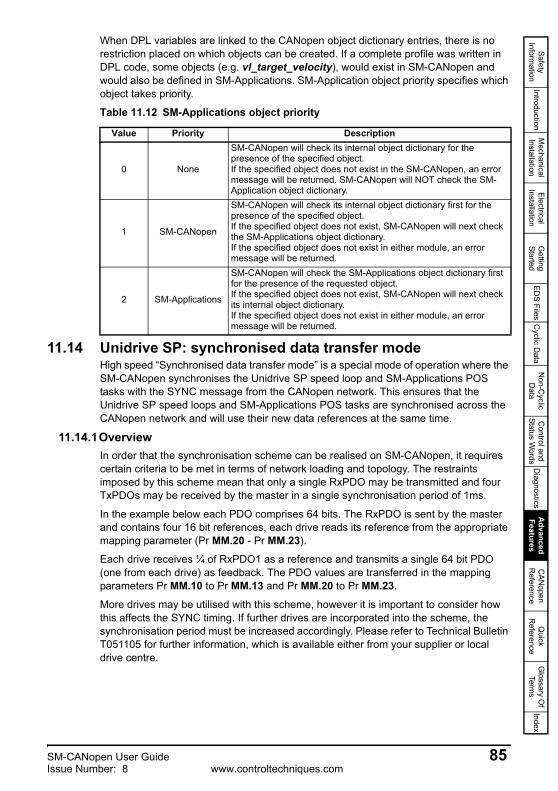
Safety Inform
ationIntroduction
Mechanical
InstallationElectrical
InstallationG
etting Started
EDS Files
Cyclic D
ataN
on-Cyclic
Data
Control and
Status Words
Diagnostics
Advanced
FeaturesC
ANopen
Reference
Quick
Reference
Glossary O
f Term
sIndex
When DPL variables are linked to the CANopen object dictionary entries, there is no restriction placed on which objects can be created. If a complete profile was written in DPL code, some objects (e.g. vl_target_velocity), would exist in SM-CANopen and would also be defined in SM-Applications. SM-Application object priority specifies which object takes priority.
11.14 Unidrive SP: synchronised data transfer modeHigh speed “Synchronised data transfer mode” is a special mode of operation where the SM-CANopen synchronises the Unidrive SP speed loop and SM-Applications POS tasks with the SYNC message from the CANopen network. This ensures that the Unidrive SP speed loops and SM-Applications POS tasks are synchronised across the CANopen network and will use their new data references at the same time.
11.14.1OverviewIn order that the synchronisation scheme can be realised on SM-CANopen, it requires certain criteria to be met in terms of network loading and topology. The restraints imposed by this scheme mean that only a single RxPDO may be transmitted and four TxPDOs may be received by the master in a single synchronisation period of 1ms.
In the example below each PDO comprises 64 bits. The RxPDO is sent by the master and contains four 16 bit references, each drive reads its reference from the appropriate mapping parameter (Pr MM.20 - Pr MM.23).
Each drive receives ¼ of RxPDO1 as a reference and transmits a single 64 bit PDO (one from each drive) as feedback. The PDO values are transferred in the mapping parameters Pr MM.10 to Pr MM.13 and Pr MM.20 to Pr MM.23.
More drives may be utilised with this scheme, however it is important to consider how this affects the SYNC timing. If further drives are incorporated into the scheme, the synchronisation period must be increased accordingly. Please refer to Technical Bulletin T051105 for further information, which is available either from your supplier or local drive centre.
Table 11.12 SM-Applications object priority
Value Priority Description
0 None
SM-CANopen will check its internal object dictionary for the presence of the specified object.If the specified object does not exist in the SM-CANopen, an error message will be returned. SM-CANopen will NOT check the SM-Application object dictionary.
1 SM-CANopen
SM-CANopen will check its internal object dictionary first for the presence of the specified object.If the specified object does not exist, SM-CANopen will next check the SM-Applications object dictionary.If the specified object does not exist in either module, an error message will be returned.
2 SM-Applications
SM-CANopen will check the SM-Applications object dictionary first for the presence of the requested object.If the specified object does not exist, SM-CANopen will next check its internal object dictionary.If the specified object does not exist in either module, an error message will be returned.
SM-CANopen User Guide 85Issue Number: 8 www.controltechniques.com
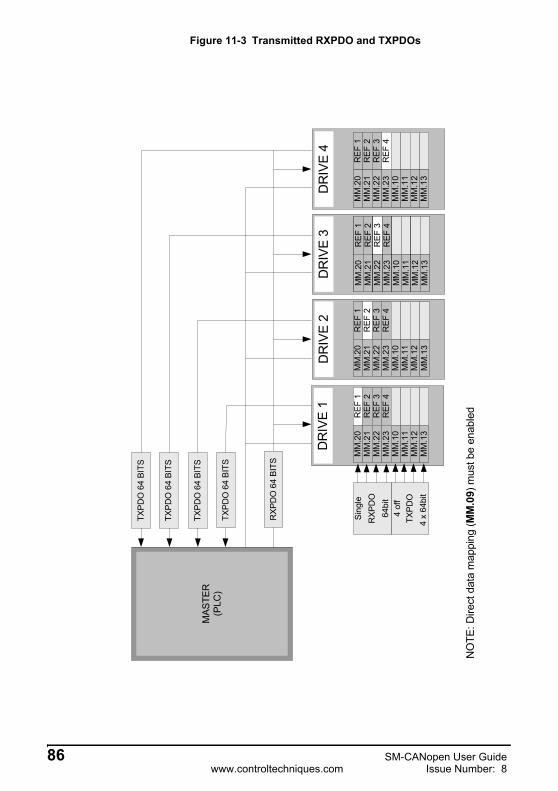
Figure 11-3 Transmitted RXPDO and TXPDOs
REF
1M
M.2
0
REF
4M
M.2
3
REF
2M
M.2
1R
EF 3
MM
.22
MM
.10
MM
.11
MM
.12
MM
.13
MAS
TER
(PLC
)
REF
1M
M.2
0
REF
4M
M.2
3
REF
2M
M.2
1R
EF 3
MM
.22
MM
.10
MM
.11
MM
.12
MM
.13
REF
1M
M.2
0
REF
4M
M.2
3
REF
2M
M.2
1R
EF 3
MM
.22
MM
.10
MM
.11
MM
.12
MM
.13
REF
1M
M.2
0
REF
4M
M.2
3
REF
2M
M.2
1R
EF 3
MM
.22
MM
.10
MM
.11
MM
.12
MM
.13
TXPD
O
RXP
DO
TXPD
O 6
4 BI
TS
TXPD
O 6
4 BI
TS
TXPD
O 6
4 BI
TS
RXP
DO
64
BITS
TXPD
O 6
4 BI
TS
DR
IVE
1D
RIV
E 2
DR
IVE
3D
RIV
E 4
NO
TE: D
irect
dat
a m
appi
ng (M
M.0
9) m
ust b
e en
able
d
Cvvdvchjvdhcvsdcvsdddsddsdfdssdfsdfsdfsdfsdfsdf
sdfsdf
Sing
le
64bi
t4
off
4 x
64bi
t
86 SM-CANopen User Guidewww.controltechniques.com Issue Number: 8

Safety Inform
ationIntroduction
Mechanical
InstallationElectrical
InstallationG
etting Started
EDS Files
Cyclic D
ataN
on-Cyclic
Data
Control and
Status Words
Diagnostics
Advanced
FeaturesC
ANopen
Reference
Quick
Reference
Glossary O
f Term
sIndex
11.14.2Configuring synchronised data transferThe following features must be enabled on SM-CANopen to implement the synchronised data transfer mode:
1. Direct data mapping enabled, set Pr MM.09 to ON.
2. Data compression enabled, set Pr MM.34 to ON.
3. Synchronisation producer enabled, set Pr MM.43 to 1.
4. Transmission type to 1, set Pr MM.41 to 1.
5. SM-CANopen must be reset by setting Pr MM.32 to ON to make the configuration changes take effect.
6. Write 1000 to Pr xx.00 and press the red button to save the parameters.
11.14.3Synchronisation modesUnidrive SP will allow one of the installed option modules to adjust the timing of the internal loops to keep it synchronised to an external signal. This module is known as the “synchronisation producer” for the Unidrive SP.
When SM-CANopen is enabled as the synchronisation producer, it will use the CANopen SYNC message as the external synchronisation signal. Every SM-CANopen on a synchronised network must be configured as the synchronisation producer for its Unidrive SP by setting Pr MM.43 to 1. Please refer to Technical Bulletin T051105 for further information, which is available either from your supplier or local drive centre.
When SM-CANopen is enabled as the syncronisation producer, the synchronisation status (Pr MM.44) and synchronisation period (Pr MM.45) parameters will be updated to indicate the current synchronisation status.
To use the synchronised data transfer mode, SM-CANopen must be fitted with V3.01.00 or later firmware and SM-Applications must have V1.03.00 or later system file installed.
NOTE
Table 11.13 Synchronisation modes
Pr MM.43 Mode Description
0 Independent SM-CANopen will not participate in the Unidrive SP inter-option synchronisation system.
1 Producer SM-CANopen will act as the “synchronisation producer” on the Unidrive SP.
2 Consumer Not valid.
If 2 or more option modules are configured to be the synchronisation producer for the Unidrive SP, the module fitted in the lowest slot will be the synchronisation producer.
NOTE
SM-CANopen User Guide 87Issue Number: 8 www.controltechniques.com

RxPDOA and TxPDOA mappingsIf synchronisation producer (Pr MM.43) and direct data mapping (Pr MM.09) are both enabled when SM-CANopen initialises, SM-CANopen will use a special operating mode for RxPDOA and TxPDOA. This special operating mode provides high speed deterministic data transfer for RxPDOA and TxPDOA data, ensuring that data received in RxPDOA is available for the POS0 task in the SM-Applications.
SM-CANopen needs to access 9 parameters in less than 90μs for deterministic data transfer, and this can only be achieved by using fixed internal mappings to drive parameters with no range checking on the data values. This is achieved by using the mappings shown in Table 11.14
The lack of range checking does not matter as each target and source drive parameter has the full 16-bit range. Meaning that the value of each pair of data bytes in RxPDOA can never exceed the range of the target parameter.
SM-CANopen will update the mapping objects for RxPDOA and TxPDOA in the CANopen object dictionary to reflect the actual mappings that are being used.
Direct data mapping uses Pr MM.10 to Pr MM.13 and Pr MM.20 to Pr MM.23 as target and source parameters. As they are 16-bit parameters, data compression (Pr MM.34) must be enabled.
Table 11.14 TxDPOA and RxPDOA data mappings
TxPDOA data bytes
Source parameter
RxPDOA data bytes
Target parameter
0, 1 Pr MM.10 0, 1 Pr MM.202, 3 Pr MM.11 2, 3 Pr MM.214, 5 Pr MM.12 4, 5 Pr MM.226, 7 Pr MM.13 6, 7 Pr MM.23
Table 11.15 RxPDOA and TxPDOA (default TxPDO1) mapping objects
Index Sub-index Mapping value XI Target parameter0x1600 - 0x17FF 0 0x040x1600 - 0x17FF 1 0x20MM1410 Pr MM.200x1600 - 0x17FF 2 0x20MM1510 Pr MM.210x1600 - 0x17FF 3 0x20MM1610 Pr MM.220x1600 - 0x17FF 4 0x20MM1710 Pr MM.23
0x1A00 - 0x1BFF 0 0x040x1A00 - 0x1BFF 1 0x20MM0A10 Pr MM.100x1A00 - 0x1BFF 2 0x20MM0B10 Pr MM.110x1A00 - 0x1BFF 3 0x20MM0C10 Pr MM.120x1A00 - 0x1BFF 4 0x20MM0D10 Pr MM.13
The actual index will be determined by the values set in 0x2800 and 0x2801 i.e. the default PDO number -1.
As the mappings for RxPDOA and TxPDOA are fixed in direct access mode, changes made to these objects will NOT affect the actual mappings used by the SM-CANopen.XI MM in the mapping value represents the hexadecimal equivalent of the slot menu, eg slot 1 (menu 15) would be MM = 0F.
NOTE
88 SM-CANopen User Guidewww.controltechniques.com Issue Number: 8
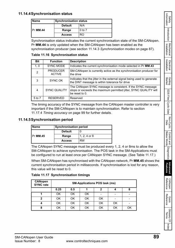
Safety Inform
ationIntroduction
Mechanical
InstallationElectrical
InstallationG
etting Started
EDS Files
Cyclic D
ataN
on-Cyclic
Data
Control and
Status Words
Diagnostics
Advanced
FeaturesC
ANopen
Reference
Quick
Reference
Glossary O
f Term
sIndex
11.14.4Synchronisation status
Synchronisation status indicates the current synchronisation state of the SM-CANopen. Pr MM.44 is only updated when the SM-CANopen has been enabled as the synchronisation producer (see section 11.14.3 Synchronisation modes on page 87).
The timing accuracy of the SYNC message from the CANopen master controller is very important if the SM-CANopen is to maintain synchronisation. Refer to section 11.17.4 Timing accuracy on page 99 for further details.
11.14.5Synchronisation period
The CANopen SYNC message must be produced every 1, 2, 4 or 8ms to allow the SM-CANopen to achieve synchronisation. The POS task in the SM-Applications must be configured to run at least once per CANopen SYNC message. (See Table 11.17.)
When SM-CANopen has synchronised with the CANopen network, Pr MM.45 shows the current synchronisation period in milliseconds. If synchronisation is lost for any reason, this value will be reset to 0.
Name Synchronisation status
Pr MM.44Default N/ARange 0 to 7Access RO
Table 11.16 Synchronisation status
Bit Function Description1, 0 SYNC MODE Indicates the current synchronisation mode selected in Pr MM.43
2 PRODUCER ACTIVE
SM-CANopen is currently active as the synchronisation producer for the drive
3 SYNC OK Indicates that the jitter in the external signal being used to generate the DINT message is within tolerance for drive
4 SYNC QUALITYThe CANopen SYNC message is consistent. If the SYNC message stops or exceeds the maximum permitted jitter, SYNC QUALITY will be reset to 0.
5 to 7 RESERVED Reserved
Name Synchronisation period
Pr MM.45Default 0Range 1, 2, 4 or 8Access RW
Table 11.17 Synchronisation timings
CANopen SYNC rate SM-Applications POS task (ms)
0.25 0.5 1 2 4 81 OK OK OK - - -2 OK OK OK OK - -4 OK OK OK OK OK -8 OK OK OK OK OK OK
SM-CANopen User Guide 89Issue Number: 8 www.controltechniques.com

11.14.6Synchronising Unidrive SP via the CANopen networkSynchronised position control allows a group of axes (drives) on a CANopen network to make their programmed position moves at the same time. This is very important in precision CNC machines, as the level of synchronisation between axes partly determines the “smoothness” of motion when following a curved profile.
Figure 11-4 and Table 11.18 describe each step of the process used to handle receipt and transmission of data and guarantee that all SM-CANopen devices respond at the same time.
11.15 Unidrive SP: position control without interpolationPosition reference interpolation is not required if the CANopen SYNC time (refer to section 11.14.5 Synchronisation period on page 89) is the same as the POS task time in the SM-Applications. The new position reference received from the CANopen master controller can be processed in the POS0 task and passed to the advanced position controller on each POS task cycle. Figure 11-5 Position control without interpolation on page 92 shows a synchronised CANopen system consisting of 4 nodes running at 1.0 Mbit/s and 1ms SYNC time. The SM-Applications POS0 task is also running at 1ms.
Table 11.18 CANopen timings
Time Description
t1
When RMINT_1MS occurs, SM-CANopen retrieves and writes RxPDOA data directly into Pr MM.20 to Pr MM.23, updates the PDO counter in Pr MM.46 then reads the values from Pr MM.10 to Pr MM.13 to generate TxPDOA. All parameter accesses are complete 70μs after RMINT_1MS occurred.
t2
The SM-Applications POS0 task will run 90μs after RMINT_POS. At this point, the new data values from RxPDOA are available to the DPL program in Pr MM.20 to Pr MM.23 and can be used to generate the new position reference for the advanced position controller. The advanced position controller will run immediately after POS0.
t3The APC has completed, so the new speed reference will be available. This is transferred into the output channel by POS1, and the results of the APC calculations can be loaded into Pr MM.10 to Pr MM.13 for the next transmission of TxPDOA.
t4 The SM-Applications system will write the output channel value to the Unidrive SP hard speed reference (Pr 3.22) just before the POS0 task actually runs.
t5 The Unidrive SP speed loop will run on RMINT and will use the updated hard speed reference value in Pr 3.22.
RxPDOA and TxPDOA is by default PDO1, but may be changed using objects 0x2801 and 0x2800.
NOTE
90 SM-CANopen User Guidewww.controltechniques.com Issue Number: 8
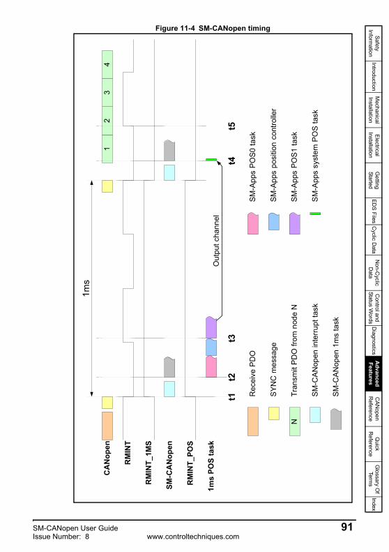
Safety Inform
ationIntroduction
Mechanical
InstallationElectrical
InstallationG
etting Started
EDS Files
Cyclic D
ataN
on-Cyclic
Data
Control and
Status Words
Diagnostics
Advanced
FeaturesC
ANopen
Reference
Quick
Reference
Glossary O
f Term
sIndex
Figure 11-4 SM-CANopen timing
12
34
CA
Nop
en
RM
INT
SM-C
AN
open
1ms
POS
task
N
Rec
eive
PD
O
Tran
smit
PD
O fr
om n
ode
N
SYN
C m
essa
ge
SM
-CA
Nop
en in
terr
upt t
ask
SM
-CA
Nop
en 1
ms
task
SM
-App
s po
sitio
n co
ntro
ller
SM
-App
s PO
S0 ta
sk
SM
-App
s PO
S1 ta
sk
SM
-App
s sy
stem
PO
S ta
sk
RM
INT_
1MS
1ms
Out
put c
hann
el
RM
INT_
POS
t1t2
t3t4
t5
SM-CANopen User Guide 91Issue Number: 8 www.controltechniques.com
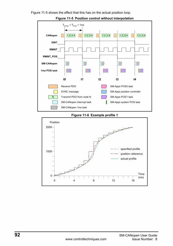
CANopen
RMINT
SM-CANopen
1ms POS task
t0 t1
N
Receive PDO
Transmit PDO from node N
SYNC message
SM-CANopen interrupt task
SM-CANopen 1ms task
SM-Apps position controller
SM-Apps POS0 task
SM-Apps POS1 task
SM-Apps system POS task
RMINT_POS
TSYNC = TPOS = 1ms
DINT
t2 t3 t4
1 2 3 4 1 2 3 41 2 3 4 1 2 3 4 1 2 3 4
Figure 11-5 shows the effect that this has on the actual position loop.
Figure 11-5 Position control without interpolation
Figure 11-6 Example profile 1
0 4 8 12 16
0
1000
2000
Time(ms)
Position
specified profile
position reference
actual profile
92 SM-CANopen User Guidewww.controltechniques.com Issue Number: 8

Safety Inform
ationIntroduction
Mechanical
InstallationElectrical
InstallationG
etting Started
EDS Files
Cyclic D
ataN
on-Cyclic
Data
Control and
Status Words
Diagnostics
Advanced
FeaturesC
ANopen
Reference
Quick
Reference
Glossary O
f Term
sIndex
11.16 Unidrive SP: position control with interpolationPosition reference interpolation is required if the synchronisation time (see Figure 11-8 Uninterpolated position profile on page 94) is different to the POS task time in the SM-Applications. Figure 11-7 Position control with interpolation shows a synchronised CANopen system consisting of 4 nodes running at 1.0 Mbit/s and 4ms SYNC time. The SM-Applications POS0 task is running at 1ms.
Figure 11-7 Position control with interpolation
When the CANopen SYNC time is 4ms, the position reference received from the master controller is the target position that must be achieved 4ms later. If the SM-Applications position controller is running every 1ms, it will try to move to the new position in 1ms, instead of 4ms. The actual movement that will be produced is shown in section 11.14.5 Synchronisation period on page 89, and looks nothing like the specifiedprofile.
CANopen
RMINT
SM-CANopen
1ms POS task
t0 t1
N
Receive PDO
Transmit PDO from node N
SYNC message
SM-CANopen interrupt task
SM-CANopen 1ms task
SM-Apps position controller
SM-Apps POS0 task
SM-Apps POS1 task
SM-Apps system POS task
RMINT_POS
DINT
1 2 3 4 1 2 3 4
t2 t3 t4
TPOS = 1ms
TSYNC = 4ms
SM-CANopen User Guide 93Issue Number: 8 www.controltechniques.com
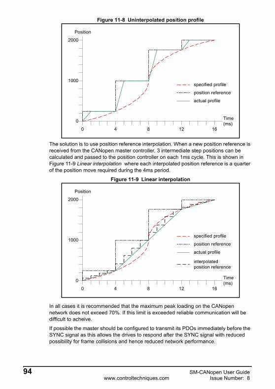
Figure 11-8 Uninterpolated position profile
The solution is to use position reference interpolation. When a new position reference is received from the CANopen master controller, 3 intermediate step positions can be calculated and passed to the position controller on each 1ms cycle. This is shown in Figure 11-9 Linear interpolation where each interpolated position reference is a quarter of the position move required during the 4ms period.
Figure 11-9 Linear interpolation
In all cases it is recommended that the maximum peak loading on the CANopen network does not exceed 70%. If this limit is exceeded reliable communication will be difficult to acheive.
If possible the master should be configured to transmit its PDOs immediately before the SYNC signal as this allows the drives to respond after the SYNC signal with reduced possibility for frame collisions and hence reduced network performance.
0 4 8 12 16
2000
1000
0 Time(ms)
specified profile
position reference
actual profile
Position
0 4 8 12 16
2000
1000
0 Time(ms)
specified profile
position reference
actual profile
interpolatedposition reference
Position
94 SM-CANopen User Guidewww.controltechniques.com Issue Number: 8

Safety Inform
ationIntroduction
Mechanical
InstallationElectrical
InstallationG
etting Started
EDS Files
Cyclic D
ataN
on-Cyclic
Data
Control and
Status Words
Diagnostics
Advanced
FeaturesC
ANopen
Reference
Quick
Reference
Glossary O
f Term
sIndex
11.16.1Timing and data transfer consistencyTo achieve good results from the inter-module synchronisation scheme it is important to understand the timing constraints of this system.
The order of events during synchronised data transfer is as follows.
1. SYNC Message received from the CANopen network.2. SM-CANopen toggles the DINT line to synchronise drive. 3. Received PDO data transferred from SM-CANopen to Pr MM.20 to Pr MM.23.4. Pr MM.46 is incremented.5. Data is transferred from Pr MM.10 to Pr MM.13 to SM-CANopen ready to be
transmitted on the next CANopen SYNC period.The transactions of data from network to drive are completed within 65us of the synchronisation message being received and are therefore within the 90us time slot allocated by the drive before the POS task begins to run. Should, however, the SYNC jitter on the network exceed +/-25us it is possible that the transactions will overrun and start to run concurrently with the POS task and its updating of values. This situation creates an inherent risk of data inconsistency within the PDO frame correlative to the amount of SYNC jitter on the network. To allow for the potential of SYNC jitter Pr MM.46 should be utilised as a final check.
It is only when the entire RxPDO frame has been received, that the value in Pr MM.46 is incremented, although values in the PDO frame may be available to be read by the SM-Applications prior to the completion of the transaction but without using Pr MM.46 it is theoretically possible for incomplete data update to be read during the frames transmission and for data inconsistency to occur.
If strict network conditions are adhered to and data is only accessed by theSM-Applications module in the POS task after Pr MM.46 has been incremented, any risk of data inconsistency is eliminated, as the entire frame is known to have been transmitted and its values updated. The user can test the value of Pr MM.46 in the DPL by using a simple comparison thus:
if #15.46 <> the_old_value_15_46% then…..
indicating the PDO has been received.
11.17 Synchronisation exampleThis example shows a scenario where the POS0 tasks of the modules in a Unidrive SP need to be synchronised with the CANopen network.
Table 11.19 on page 96 shows 2 SM-Applications modules synchronised to CANopen. Slot 1 has a 500us position task, Slot 2 has a 1ms position task and the CANopen network has a 2ms synchronisation period.
SM-CANopen User Guide 95Issue Number: 8 www.controltechniques.com

11.17.1Internal interruptsRMINT, RMINT_1MS and RMINT_POSRMINT is a hardware interrupt within the Unidrive SP and is used to control the execution of the Unidrive SP speed loop. It is generated nominally every 250μs, but the internal phase-locked loop may be adjusted to synchronise to an external signal (see section 11.17.4 Timing accuracy on page 99 for more information). RMINT_1MS is a software interrupt that is generated by SM-CANopen on every 4th RMINT to produce an internal 1ms task.
RMINT_POS is also a software interrupt, and is generated by SM-Applications to produce the POS0 and POS1 tasks. The number of RMINT interrupts required to generate each RMINT_POS is controlled by Pr MM.12 allowing the timing of the POS tasks to be varied as required.
Table 11.19 Parameter settings for synchronisation
Slot Parameter Value DescriptionSlot1 SM-
ApplicationsPr MM.12 2 500us task period
#91.21 2 Inter-option Sync Consumer
#91.22 6 (Read only)Inter-option Sync Consumer status
achieved.Slot2 SM-
ApplicationsPr MM.12 3 1ms task period
#91.21 2 Inter-option Sync Consumer
#91.22 6 (Read only)Inter-option Sync Consumer status
achieved.Slot3 SM-CANopen Pr MM.45 2 2ms CANopen
synchronisation
Pr MM.43 1 Inter-option Sync Producer
Pr MM.44 29 (Read only) Inter-option Sync Producer status achieved
(bits 0, 2, 3, and 4 set)
To guarantee synchronisation between SM-CANopen and SM-Applications on a Unidrive SP, the RMINT_1MS and RMINT_POS must be generated from the same RMINT interrupt. This is achieved by specifying SM-CANopen as the “synchronisation producer” and SM-Applications as the “synchronisation consumer”. SM-Applications will synchronise to the same RMINT as SM-CANopen and synchronisation between the modules is guaranteed.
The SM-Applications must be loaded with system file version 1.03.00 or later to guarantee synchronisation between RMINT_1MS and RMINT_POS.
NOTE
NOTE
96 SM-CANopen User Guidewww.controltechniques.com Issue Number: 8
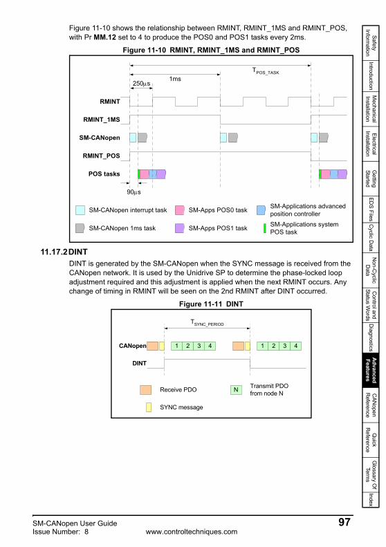
Safety Inform
ationIntroduction
Mechanical
InstallationElectrical
InstallationG
etting Started
EDS Files
Cyclic D
ataN
on-Cyclic
Data
Control and
Status Words
Diagnostics
Advanced
FeaturesC
ANopen
Reference
Quick
Reference
Glossary O
f Term
sIndex
Figure 11-10 shows the relationship between RMINT, RMINT_1MS and RMINT_POS, with Pr MM.12 set to 4 to produce the POS0 and POS1 tasks every 2ms.
Figure 11-10 RMINT, RMINT_1MS and RMINT_POS
11.17.2DINTDINT is generated by the SM-CANopen when the SYNC message is received from the CANopen network. It is used by the Unidrive SP to determine the phase-locked loop adjustment required and this adjustment is applied when the next RMINT occurs. Any change of timing in RMINT will be seen on the 2nd RMINT after DINT occurred.
Figure 11-11 DINT
RMINT
POS tasks
SM-Applications advancedposition controllerSM-Apps POS0 task
SM-Apps POS1 task SM-Applications systemPOS task
RMINT_1MS
250μs
90μs
RMINT_POS
SM-CANopen
1msTPOS_TASK
SM-CANopen interrupt task
SM-CANopen 1ms task
CANopen
Receive PDO Transmit PDOfrom node N
SYNC message
DINT
TSYNC_PERIOD
1 2 4 1 2 3 4
N
3
SM-CANopen User Guide 97Issue Number: 8 www.controltechniques.com
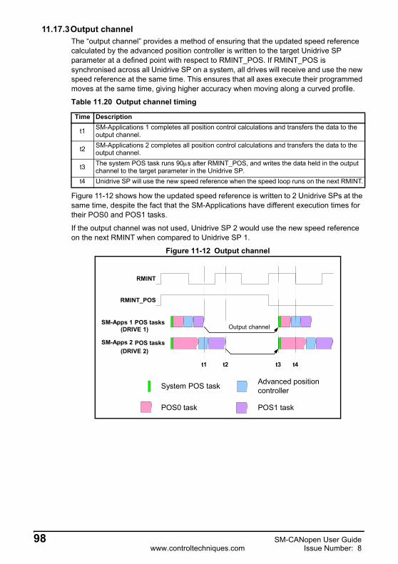
11.17.3Output channelThe “output channel” provides a method of ensuring that the updated speed reference calculated by the advanced position controller is written to the target Unidrive SP parameter at a defined point with respect to RMINT_POS. If RMINT_POS is synchronised across all Unidrive SP on a system, all drives will receive and use the new speed reference at the same time. This ensures that all axes execute their programmed moves at the same time, giving higher accuracy when moving along a curved profile.
Figure 11-12 shows how the updated speed reference is written to 2 Unidrive SPs at the same time, despite the fact that the SM-Applications have different execution times for their POS0 and POS1 tasks.
If the output channel was not used, Unidrive SP 2 would use the new speed reference on the next RMINT when compared to Unidrive SP 1.
Figure 11-12 Output channel
Table 11.20 Output channel timing
Time Description
t1 SM-Applications 1 completes all position control calculations and transfers the data to the output channel.
t2 SM-Applications 2 completes all position control calculations and transfers the data to the output channel.
t3 The system POS task runs 90μs after RMINT_POS, and writes the data held in the output channel to the target parameter in the Unidrive SP.
t4 Unidrive SP will use the new speed reference when the speed loop runs on the next RMINT.
Output channel
t2
SM-Apps 1 POS tasks
RMINT_POS
RMINT
SM-Apps 2 POS tasks
System POS task
POS0 task
Advanced positioncontroller
POS1 task
t1 t3 t4
(DRIVE 1)
(DRIVE 2)
98 SM-CANopen User Guidewww.controltechniques.com Issue Number: 8

Safety Inform
ationIntroduction
Mechanical
InstallationElectrical
InstallationG
etting Started
EDS Files
Cyclic D
ataN
on-Cyclic
Data
Control and
Status Words
Diagnostics
Advanced
FeaturesC
ANopen
Reference
Quick
Reference
Glossary O
f Term
sIndex
11.17.4Timing accuracyTable 11.21 shows the timing specifications for a synchronised CANopen network.
11.17.5SYNC absolute timing accuracyThe Unidrive SP phase-locked loop generates RMINT nominally every 250μs, but this can be adjusted by +/-1μs to compensate for small differences in crystal clock frequencies between different devices. RMINT cannot be adjusted outside of this limit, so this gives a maximum adjustment of 1μs for every 250μs, i.e. 0.4%. The CANopen master must be able to produce the SYNC message nominally every 1, 2, 4 or 8ms, accurate to +/-0.4%.
If the CANopen master is configured to produce the SYNC message every 1ms, but actually produces it every 1.002ms, this equates to an error of 0.2% so will not cause a problem. SM-CANopen will synchronise to the SYNC message and adjust the timing of the Unidrive SP phase-locked loop to generate RMINT every 250.5μs. The 1ms tasks in SM-CANopen and SM-Applications will now run every 1.002ms, and remain fully synchronised with the CANopen master.
11.17.6SYNC jitter“Jitter” is the term used for timing variations seen in a signal, but these timing variations will always average out to 0 over a period of time. “SYNC jitter” is the continuous variation in the actual timing between SYNC messages. SM-CANopen can handle “SYNC jitter” of +/- 25μs without losing synchronisation.
If the CANopen master is producing the SYNC messages nominally every 1.002ms with 20ms jitter, the timing between SYNC messages will range from 1.982 to 1.022ms. However, over a period of time, jitter will cancel out, and the average SYNC message time seen by SM-CANopen will be 1.002ms.
Table 11.21 Synchronised CANopen specifications
Function Range Description
Master SYNC accuracy +/- 0.4%
The maximum range in the nominal SYNC time produced by the CANopen master for SM-CANopen to maintain synchronisation.
Master SYNC jitter 25μs max The maximum permitted jitter in the SYNC message for SM-CANopen to maintain synchronisation.
Slave RMINT jitter +/-2μs The maximum jitter in the RMINT interrupts between any 2 Unidrive SPs synchronised using SM-CANopen.
Please refer to Pr MM.46 (11.16.1Timing and data transfer consistency on page 95).NOTE
SM-CANopen User Guide 99Issue Number: 8 www.controltechniques.com

11.17.7Slave RMINT accuracyThe accuracy of the synchronisation process using SM-CANopen is quoted as the maximum jitter that will be seen between the RMINT signals of any 2 Unidrive SPs on the CANopen network.
Maximum RMINT jitter = +/- 2μs
As the Unidrive SP speed loop runs every 250μs, the maximum synchronisation jitter BETWEEN ANY 2 DRIVES equates to 0.8% across the CANopen network.
Figure 11-13 shows how the timings of RMINT may vary between 4 Unidrive SPs across a network, but the difference between any 2 RMINT signals will not exceed +/-2μs.
Figure 11-13
In this case, the worst case delay between RMINTs is between node 2 and node 3. The difference between any other pair of nodes is always less then 2μs.
11.17.8Network loadThe network load determines the fastest update time that can be achieved for a given CANopen network. Network load depends on the network data rate, CANopen SYNC rate, total number of devices on the network and amount of data for each device.
If the load factor (see equations below) is < 0.85, the required performance can normally be achieved with an error-free CANopen network.
where:
TBit = bit time in microseconds (see Table 11.22)
TSync = SYNC message time in milliseconds.
NPDOBits = number of bits in each TxPDO or RxPDO that will be transmitted.
NBytes = number of data bytes (0 to 8) for the RxPDO or TxPDO.
RMINT (N2)
2μs
RMINT (N1)
RMINT (N3)
RMINT (N4)
Load factor100 47 NPDOBits∑+( ) TBit×[ ]+
TSync 1000×--------------------------------------------------------------------------------------=
NPDOBits 47 8 NBytes×( )+=
100 SM-CANopen User Guidewww.controltechniques.com Issue Number: 8
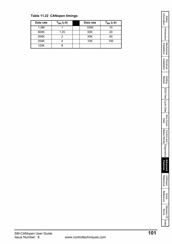
Safety Inform
ationIntroduction
Mechanical
InstallationElectrical
InstallationG
etting Started
EDS Files
Cyclic D
ataN
on-Cyclic
Data
Control and
Status Words
Diagnostics
Advanced
FeaturesC
ANopen
Reference
Quick
Reference
Glossary O
f Term
sIndex
Table 11.22 CANopen timings
Data rate TBit (μs) Data rate TBit (μs)
1.0M 1 100K 10800K 1.25 50K 20500K 2 20K 50250K 4 10K 100125K 8
SM-CANopen User Guide 101Issue Number: 8 www.controltechniques.com
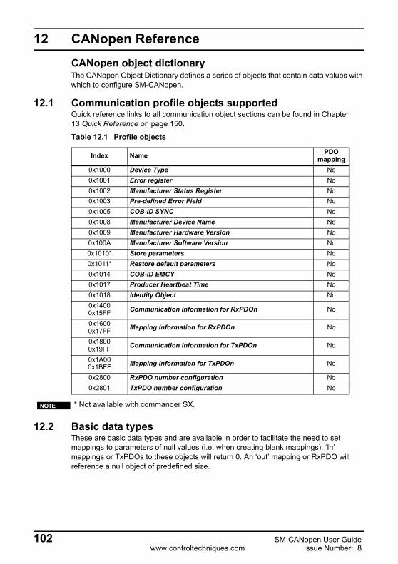
12 CANopen Reference
CANopen object dictionaryThe CANopen Object Dictionary defines a series of objects that contain data values with which to configure SM-CANopen.
12.1 Communication profile objects supportedQuick reference links to all communication object sections can be found in Chapter 13 Quick Reference on page 150.
12.2 Basic data typesThese are basic data types and are available in order to facilitate the need to set mappings to parameters of null values (i.e. when creating blank mappings). ‘In’ mappings or TxPDOs to these objects will return 0. An ‘out’ mapping or RxPDO will reference a null object of predefined size.
Table 12.1 Profile objects
Index Name PDO mapping
0x1000 Device Type No0x1001 Error register No0x1002 Manufacturer Status Register No0x1003 Pre-defined Error Field No0x1005 COB-ID SYNC No0x1008 Manufacturer Device Name No0x1009 Manufacturer Hardware Version No0x100A Manufacturer Software Version No0x1010* Store parameters No0x1011* Restore default parameters No0x1014 COB-ID EMCY No0x1017 Producer Heartbeat Time No0x1018 Identity Object No0x14000x15FF Communication Information for RxPDOn No
0x16000x17FF Mapping Information for RxPDOn No
0x18000x19FF Communication Information for TxPDOn No
0x1A000x1BFF Mapping Information for TxPDOn No
0x2800 RxPDO number configuration No0x2801 TxPDO number configuration No
* Not available with commander SX.NOTE
102 SM-CANopen User Guidewww.controltechniques.com Issue Number: 8

Safety Inform
ationIntroduction
Mechanical
InstallationElectrical
InstallationG
etting Started
EDS Files
Cyclic D
ataN
on-Cyclic
Data
Control and
Status Words
Diagnostics
Advanced Features
CA
Nopen
Reference
Quick
Reference
Glossary O
f Term
sIndex
For example if only a single 16 bit word is used within a PDO the remaining words that are unused within the particular drive should be mapped to a null data type of the appropriate size.
12.3 Device type
device type indicates the current configuration of the drive and SM-CANopen and is used by some CANopen master controllers to ensure that the correct EDS file is being used.
device type is constructed using the values as indicated in Table 12.4 and Table 12.5.
Table 12.2 Basic data types
Index Name Size
0x0002 Integer8 80x0003 Integer16 160x0004 Integer32 320x0005 Unsigned8 80x0006 Unsigned16 160x0007 Unsigned32 32
Index 0x1000 Sub-index 0 Access RODefault N/A Data type UNSIGNED32 Object code VAR
Table 12.3 Device type
Additional informationDevice profile number
Mode Typeb31-b24
Refer to Table 12.5b23-b16
Refer to Table 12.4b15-b0
Refer to Table 12.4
Table 12.4 Device profile number and type
Type Device profile number Description
0x00 0x0000 All device profiles are disabled
0x01 0x0192Device profile DS402 V1.1 enabled, drive is running in Servo, open loop or regen mode (see section 12.15.1 Enable DSP402 device profiles on page 133).
0x03 0x0192Device profile DS402 V1.1 enabled, drive is running in closed loop or servo mode (see section 12.15.1 Enable DSP402 device profiles on page 133).
SM-CANopen User Guide 103Issue Number: 8 www.controltechniques.com

The mode byte is manufacturer-specific and is specified in Table 12.5.
12.3.1 Error register
The error register is used by SM-CANopen to indicate that an error has occurred. If a bit is set to 1, the specified error has occurred. The error register is part of the emergency object, refer to section 12.13 Emergency object on page 130 for further details.
12.3.2 Manufacturer status register
The manufacturer status register is mapped directly to the status word (Pr 10.40) in the drive. See section 9.3 Status word on page 64 for more details about the drive status word.
12.3.3 Pre-defined error field
Table 12.5 Mode Bytes
Mode Setting Description
b26-b24 Drive mode
Indicates the operating mode of the drive.0 = SE mode (000)1 = open loop (001)2 = closed loop (010)3 = servo (011)4 = regen (111)
b27 Data compression enabled
Set to 1 if data compression (Pr MM.34) is enabled. This affects the data size used by drive parameters, so a different EDS file must be used.
b28 SM-Applications fitted Set to 1 if an SM-Applications is fitted to the drive.b31-b29 Reserved Reserved.
Index 0x1001 Sub-index 0 Access RODefault N/A Data type UNSIGNED8 Object code VAR
Table 12.6 Error register bits
Bit Error0 Generic error1 Current2 Voltage3 Temperature4 Communication error5 Device profile specific6 Reserved7 Manufacturer specific
Index 0x1002 Sub-index 0 Access RODefault N/A Data type UNSIGNED32 Object code VAR
Index 0x1003Object code ARRAYData type UNSIGNED32
104 SM-CANopen User Guidewww.controltechniques.com Issue Number: 8

Safety Inform
ationIntroduction
Mechanical
InstallationElectrical
InstallationG
etting Started
EDS Files
Cyclic D
ataN
on-Cyclic
Data
Control and
Status Words
Diagnostics
Advanced Features
CA
Nopen
Reference
Quick
Reference
Glossary O
f Term
sIndex
The pre-defined error field returns 32-bit error code containing data from the last 4 emergency messages that were sent. If less than 4 emergency objects have been sent, the higher sub-indexes will not exist.
number of errors
Sub-index 0 is an unsigned8 data type which indicates the highest sub-index for the pre-defined error field. The rest of the array are unsigned32 data types.
error field 1
Returns the last emergency object codes.
error field 2
Returns the 2nd last emergency object codes.
error field 3
Returns the 3rd last emergency object codes.
error field 4
Returns the 4th last emergency object codes.
12.3.4 COB-ID SYNC
COB-ID SYNC defines the COB-ID that will be used for the synchronisation (SYNC) object. The SM-CANopen receives the SYNC message, but it cannot be used to generate the SYNC object.
The upper 3 bits (b31-b29) are used to specify the SYNC behaviour of SM-CANopen.
Table 12.7 pre-defined error field
Byte 3 Byte 2 Byte 1 Byte 0SM-CANopen error code (Pr MM.50) Drive trip code (Pr 10.20) Emergency object error code
Index 0x1003 Sub-index 0 Access RODefault 4 Data type UNSIGNED8 Object code VAR
Index 0x1003 Sub-index 1 Access RODefault N/A Data type UNSIGNED32 Object code VAR
Index 0x1003 Sub-index 2 Access RODefault N/A Data type UNSIGNED32 Object code VAR
Index 0x1003 Sub-index 3 Access RODefault N/A Data type UNSIGNED32 Object code VAR
Index 0x1003 Sub-index 4 Access RODefault N/A Data type UNSIGNED32 Object code VAR
Index 0x1005 Sub-index 0 Access RWDefault 0x00000080 Data type UNSIGNED32 Object code VAR
b31 b30 b29 b28 - b11 b10 - b00 0 0 00000000000000000 11-bit CAN-ID
SM-CANopen User Guide 105Issue Number: 8 www.controltechniques.com
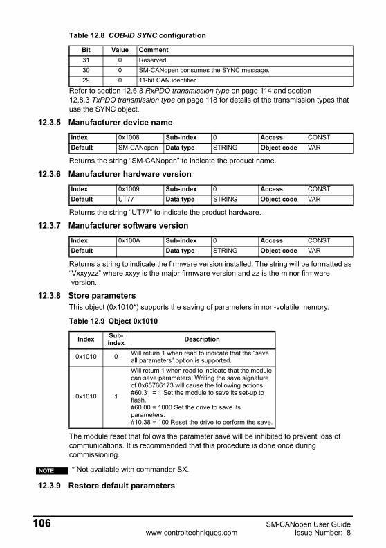
Refer to section 12.6.3 RxPDO transmission type on page 114 and section 12.8.3 TxPDO transmission type on page 118 for details of the transmission types that use the SYNC object.
12.3.5 Manufacturer device name
Returns the string “SM-CANopen” to indicate the product name.
12.3.6 Manufacturer hardware version
Returns the string “UT77” to indicate the product hardware.
12.3.7 Manufacturer software version
Returns a string to indicate the firmware version installed. The string will be formatted as “Vxxyyzz” where xxyy is the major firmware version and zz is the minor firmware version.
12.3.8 Store parametersThis object (0x1010*) supports the saving of parameters in non-volatile memory.
The module reset that follows the parameter save will be inhibited to prevent loss of communications. It is recommended that this procedure is done once during commissioning.
12.3.9 Restore default parameters
Table 12.8 COB-ID SYNC configuration
Bit Value Comment31 0 Reserved.30 0 SM-CANopen consumes the SYNC message.29 0 11-bit CAN identifier.
Index 0x1008 Sub-index 0 Access CONSTDefault SM-CANopen Data type STRING Object code VAR
Index 0x1009 Sub-index 0 Access CONSTDefault UT77 Data type STRING Object code VAR
Index 0x100A Sub-index 0 Access CONSTDefault Data type STRING Object code VAR
Table 12.9 Object 0x1010
Index Sub-index Description
0x1010 0 Will return 1 when read to indicate that the “save all parameters” option is supported.
0x1010 1
Will return 1 when read to indicate that the module can save parameters. Writing the save signature of 0x65766173 will cause the following actions.#60.31 = 1 Set the module to save its set-up to flash.#60.00 = 1000 Set the drive to save its parameters.#10.38 = 100 Reset the drive to perform the save.
* Not available with commander SX.NOTE
106 SM-CANopen User Guidewww.controltechniques.com Issue Number: 8

Safety Inform
ationIntroduction
Mechanical
InstallationElectrical
InstallationG
etting Started
EDS Files
Cyclic D
ataN
on-Cyclic
Data
Control and
Status Words
Diagnostics
Advanced Features
CA
Nopen
Reference
Quick
Reference
Glossary O
f Term
sIndex
With this object (0x1011*) the default values of parameters according to the communication or device profile are restored.
The module reset that follows the parameter save will be inhibited to prevent loss of communications. This will allow the communication parameters to be configured prior to a reset.
Stored objectsThe following objects will always be stored in internal flash.
0x1005 – COB-ID SYNC0x1014 – COB-ID EMCY0x1017 – Producer Heartbeat time0x2800 – RxPDO number configuration0x2801 – TxPDO number configuration0x1400 - 0x1BFF – PDO configuration objectsThe following objects will only be stored in internal flash if Pr MM.42 is 0.0x6042 – vl_target_velocity0x6044 – vl_control_effort0x6046 – vl_velocity_min_max_amount0x6048 – vl_velocity_acceleration0x6049 – vl_velocity_deceleration0x604C – vl_dimension_factor0x605A – quick_stop_option_code0x605B – shut_down_option_code0x605C – disable_operation_option_code0x6060 – modes_of_operation0x6071 – target_torque0x6087 – torque_slope0x6088 – torque_profile_type
Objects defined by object association in an SM-Applications module will not get saved in internal flash due to the time required to discover available objects and the space that would be required to store the potentially large number of objects. If these objects need saving then it will be the responsibility of the user program to ensure they are stored.
Table 12.10 Object 0x1011
Index Sub-index Description
0x1011 0 Will return 1 when read to indicate that the “restore default parameters” option is supported.
0x1011 1
Will return 1 when read to indicate that the module can restore parameters. Writing the save signature of 0x64616F6C will cause the following actions.#60.30 = 1 Set the module to restore its defaults.#60.00 = #11.46 Set the drive to restore its previous defaults (automatically converted on SK).#10.38 = 100 Reset the drive to perform the save.
* Not available with commander SX.NOTE
SM-CANopen User Guide 107Issue Number: 8 www.controltechniques.com

12.3.10 COB-ID EMCY
COB-ID EMCY defines the COB-ID to be used for the emergency object.
The upper 3 bits (b31-b29) are used to specify the emergency object behaviour of SM-CANopen.
Refer to section 12.13 Emergency object on page 130 for full details about the emergency object.
12.3.11 Producer heartbeat time
The “heartbeat protocol” is a node protection system or error control service. A “heartbeat producer” is usually a CANopen slave device which transmits a heartbeat message cyclically. This message is received by a one or more “heartbeat consumer” devices, usually the CANopen master controller, and indicates to the master controller that the slave device is communicating successfully.
If the heartbeat message is not received within the defined time period, a “heartbeat event” will be generated in the master controller, allowing it to take appropriate action to ensure system safety is maintained.
The producer heartbeat time defines the cyclic time period (in milliseconds) forSM-CANopen to transmit the heartbeat message. A value of 0 disables the heartbeat message. The heartbeat message also includes the current NMT state of the SM-CANopen.
The SM-CANopen will start transmitting the heartbeat message as soon as it is enabled. If the producer heartbeat time is set >0 at power up, SM-CANopen will start transmitting the heartbeat message when the transition from BOOTUP to PRE-OPERATIONAL occurs. In this case, the boot-up message is regarded as the first heartbeat message.
Index 0x1014 Sub-index 0 Access RW
Default 0x00000080 + node address Data type UNSIGNED32 Object code VAR
b31 b30 b29 b28 - b11 b10 - b00 0 0 00000000000000000 11-bit ID
Table 12.11 COB-ID SYNC configuration
Bit Value Comment31 0 EMERGENCY object always exists30 0 Reserved29 0 11-bit CAN identifier
Index 0x1017 Sub-index 0 Access RWDefault 0 Data type UNSIGNED16 Object code VAR
Table 12.12 SM-CANopen operating states
State Operating state0 BOOTUP4 STOPPED5 OPERATIONAL
127 PRE-OPERATIONAL
108 SM-CANopen User Guidewww.controltechniques.com Issue Number: 8

Safety Inform
ationIntroduction
Mechanical
InstallationElectrical
InstallationG
etting Started
EDS Files
Cyclic D
ataN
on-Cyclic
Data
Control and
Status Words
Diagnostics
Advanced Features
CA
Nopen
Reference
Quick
Reference
Glossary O
f Term
sIndex
12.3.12 Identity object
Identity object returns general information about the SM-CANopen.
Number of entries
Returns the highest sub-index available for the identity object.
Vendor ID
Returns the CANopen vendor ID (0xF9) for Control Techniques.
Product code
Returns the SM-CANopen module ID code of 408 (refer to section 10.3 SM-CANopen node address on page 67).
Revision number
Returns the SM-CANopen firmware version. Revision number will consist of the Pr MM.02 in the high data word, and Pr MM.51 in the low data word (see section 10.3 SM-CANopen node address on page 67).
Serial number
Returns the SM-CANopen serial number, also available as Pr 61.35. This value is programmed during manufacture and cannot be changed.
12.4 Flexible PDO numbering (0x2800 and 0x2801)This functionality is supported from Version 02.01.00 onwards. The behaviour of the PDO configuration objects will be changed in order to conform to the CANopen specification, whilst still offering as much flexibility as possible.There are 4 Tx and 4 Rx PDOs available in the module, these PDOs will be referred to as PDOs A, B,C and D. Each of these PDOs can be configured to be any of the 512 available PDOs, by default the configuration will be PDOA = 1, PDOB = 3, PDOC = 5 and PDOD = 6 (for
Index 0x1018Object code RECORDData type UNSIGNED32
Index 0x1018 Sub-index 0 Access RODefault 4 Data type UNSIGNED8
Index 0x1018 Sub-index 1 Access RODefault 0xF9 Data type UNSIGNED32
Index 0x1018 Sub-index 2 Access RODefault 408 Data type UNSIGNED32
Index 0x1018 Sub-index 3 Access RODefault N/A Data type UNSIGNED32
Table 12.13 Revision number
Major revision(b31 - b16)
Minor revision(b15 - b0)
Pr MM.02 Pr MM.51
Index 0x1018 Sub-index 4 Access RODefault N/A Data type UNSIGNED32
SM-CANopen User Guide 109Issue Number: 8 www.controltechniques.com

both TxPDOs and RxPDOs). The configuration of available PDOs will be possible through 2 new manufacturer specific objects accessible by the SDOs, namely objects 0x2800 and 0x2801 which manipulate the RxPDOs and TxPDOs respectively.
If a configuration using non-default or flexible numbering is required, the index number for the PDO communication objects must be derived by subtracting 1 from the PDO number and adding this number to the base address e.g. for 0x1600 PDO3 = 0x1602 (mapping information for RxPDOs).
12.5 Mapping parameter valuesWhen setting up cyclic data to contain specific parameters this may be done in two ways:
1. The first method is to use the mapping parameters Pr MM.10 - Pr MM.13 and Pr MM.20 - Pr MM.23.
2. The second is to use SDOs to set the mappings. When this is done the entries take the following form:
These are used with object 0x1600 - 0x17FF and object 0x1A00 - 0x1BFF for RxPDO and TxPDO mapping respectively. To map RxPDOA(1) to Pr 1.21, the mapping parameter would be set to 0x20011520 (index = 0x2001, sub-index = 0x15, object length = 0x20, i.e. 32 bits).
Refer to section 8.1 Service data object (SDO) parameter access on page 50 for more details on how to access drive parameters.
Table 12.14 PDO Number Changes
PDO Details Object to ChangePDO PDO Default Index Sub-index
RxPDOA RxPDO1 2800 01RxPDOB RxPDO3 2800 02RxPDOC RxPDO5 2800 03RxPDOD RxPDO6 2800 04TxPDOA TxPDO1 2801 01TxPDOB TxPDO3 2801 02TxPDOC TxPDO5 2801 03TxPDOD TxPDO6 2801 04
The PDO number written to these objects is the required PDO number -1.NOTE
b31 – b16 b15 – b8 b7 – b0Index Sub-index Object length (in bits)
110 SM-CANopen User Guidewww.controltechniques.com Issue Number: 8

Safety Inform
ationIntroduction
Mechanical
InstallationElectrical
InstallationG
etting Started
EDS Files
Cyclic D
ataN
on-Cyclic
Data
Control and
Status Words
Diagnostics
Advanced Features
CA
Nopen
Reference
Quick
Reference
Glossary O
f Term
sIndex
12.5.1 RxPDO number configuration
This object will be used for configuring the available RxPDOs.
12.5.2 TxPDO number configurationThis object will be used for configuring the available TxPDOs.
Index 0x2800 Sub-index 0 Access ROLargest sub-index supported Value = 4
Index 0x2800 Sub-index 1 Access RWPDO number for RxPDO A* Range 0 to 511
Index 0x2800 Sub-index 2 Access RWPDO number for RxPDO B* Range 0 to 511
Index 0x2800 Sub-index 3 Access RWPDO number for RxPDO C* Range 0 to 511
Index 0x2800 Sub-index 4 Access RWPDO number for RxPDO D* Range 0 to 511
Index Sub-index Description
0x2800 0Will return 4 when read indicating the maximum sub-index and number of PDOs supported.
0x2800 1- 4
Are used to read and set the RxPDO number for each of the 4 configurable RxPDOs. The number is specified as required number less 1. That is PDO1 would be represented as 0.
* The actual index number is calculated by subtracting 1 from the PDO number and adding this number to the base address e.g. for 0x1600 PDO3 = 0x1602.
NOTE
Index 0x2801 Sub-index 0 Access ROLargest sub-index supported Value = 4
Index 0x2801 Sub-index 1 Access RWPDO number for TxPDO A* Range 0 to 511
Index 0x2801 Sub-index 2 Access RWPDO number for TxPDO B* Range 0 to 511
Index 0x2801 Sub-index 3 Access RWPDO number for TxPDO C* Range 0 to 511
Index 0x2801 Sub-index 4 Access RWPDO number for TxPDO D* Range 0 to 511
SM-CANopen User Guide 111Issue Number: 8 www.controltechniques.com

12.5.3 Communication information for RxPDOThis section contains the communication parameters for the receive PDOs.
Index Sub-index Description
0x2801 0Will return 4 when read indicating the maximum sub-index and number of PDOs supported.
0x2801 1- 4
Are used to read and set the TxPDO number for each of the 4 configurable TxPDOs. The number is specified as required number less 1. That is PDO1 would be represented as 0.
* The actual index number is calculated by subtracting 1 from the PDO number and adding this number to the base address e.g. for 0x1600 PDO3 = 0x1602.
NOTE
Any modifications to the configuration of PDO A carried out over the SDO protocol will result in the mode parameter Pr MM.05 being set to 300. This will be used to indicate that the configuration in the set-up menu is not currently being used. The Download To Module Pr MM.31 routine has been updated to store all suitable objects from the communication and profile area of the object dictionary. If the SM-Applications Object Priority parameter Pr MM.42 is set, the objects in the profile area will not get saved. When the option module is defaulted the stored objects will be erased.
At start-up, the module will load values that have been stored in its internal flash into the object dictionary. Values for PDO A configuration objects will only be loaded if Pr MM.05 is set to 300. If there are no values stored in flash and Pr MM.05 is set to 300 then PDO A will be left in defaults. Please refer to Pr MM.05 in section 5-10 SDO Configuration on page 35.
NOTE
Index 0x1400-0x15FF Sub-index 0 Access RO
Largest sub-index supported Size
Index 0x1400-0x15FF Sub-index 1 Access RO
COB-ID used by PDO Size
Index 0x1400-0x15FF Sub-index 2 Access RW
Transmission type Size
Index 0x1400-0x15FF Sub-index 3 Access RW
Inhibit time (not used for RxPDO) Size
Index 0x1400-0x15FF Sub-index 4 Access RW
Compatibility entry Size
112 SM-CANopen User Guidewww.controltechniques.com Issue Number: 8

Safety Inform
ationIntroduction
Mechanical
InstallationElectrical
InstallationG
etting Started
EDS Files
Cyclic D
ataN
on-Cyclic
Data
Control and
Status Words
Diagnostics
Advanced Features
CA
Nopen
Reference
Quick
Reference
Glossary O
f Term
sIndex
12.6 RxPDO communication parameters
This section contains the communication parameters for the RxPDOs.SM-CANopen supports a total of 4 RxPDOs. Each PDO has a main index assigned to it, with individual parameters for the PDO accessed using sub-indexes.
All RxPDO configuration parameters are dynamic (any changes made to these parameters will take effect immediately).
12.6.1 Number of entries
Defines the largest sub-index supported for the specified RxPDO.
12.6.2 RxPDO COB-ID
Index 0x1400-0x15FF Sub-index 5 Access RW
Event timer Size
Index 0x1400-0x15FFObject code RecordData type PDOCommPar
Table 12.15 Supported RxPDOs
RxPDO IndexA 0x1400-0x15FFB 0x1400-0x15FFC 0x1400-0x15FFD 0x1400-0x15FF
Index 0x1400-0x15FF Sub-index 0Data type UNSIGNED8 Access RO
Table 12.16 RxPDO number of entries
RxPDO Index ValueA 0x1400-0x15FF 5B 0x1400-0x15FF 5C 0x1400-0x15FF 5D 0x1400-0x15FF 5
Where the range for the index is determined by the PDO numbers set in object 0x2800.NOTE
Index 0x1400-0x15FF Sub-index 1Data type UNSIGNED32 Access RW
SM-CANopen User Guide 113Issue Number: 8 www.controltechniques.com
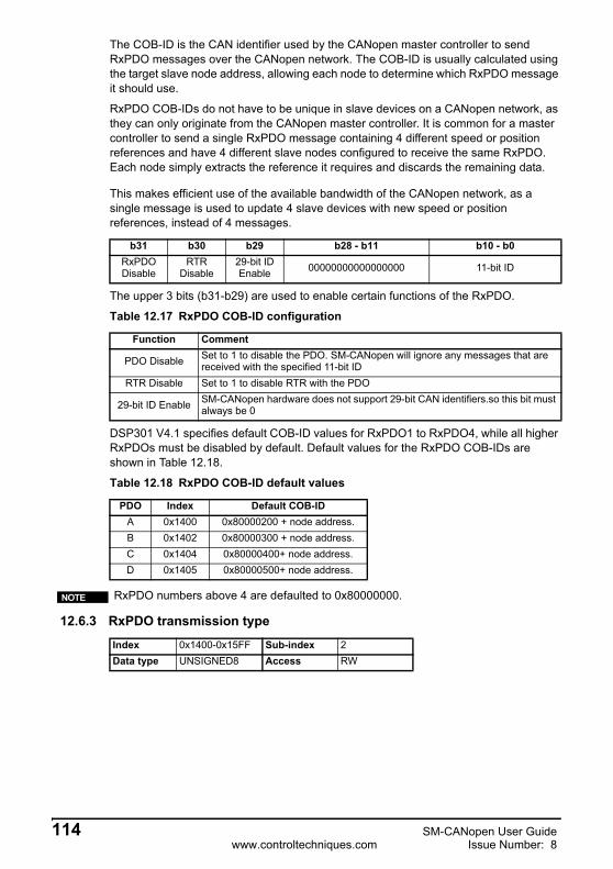
The COB-ID is the CAN identifier used by the CANopen master controller to send RxPDO messages over the CANopen network. The COB-ID is usually calculated using the target slave node address, allowing each node to determine which RxPDO message it should use.
RxPDO COB-IDs do not have to be unique in slave devices on a CANopen network, as they can only originate from the CANopen master controller. It is common for a master controller to send a single RxPDO message containing 4 different speed or position references and have 4 different slave nodes configured to receive the same RxPDO. Each node simply extracts the reference it requires and discards the remaining data.
This makes efficient use of the available bandwidth of the CANopen network, as a single message is used to update 4 slave devices with new speed or position references, instead of 4 messages.
The upper 3 bits (b31-b29) are used to enable certain functions of the RxPDO.
DSP301 V4.1 specifies default COB-ID values for RxPDO1 to RxPDO4, while all higher RxPDOs must be disabled by default. Default values for the RxPDO COB-IDs are shown in Table 12.18.
12.6.3 RxPDO transmission type
b31 b30 b29 b28 - b11 b10 - b0RxPDO Disable
RTR Disable
29-bit ID Enable 00000000000000000 11-bit ID
Table 12.17 RxPDO COB-ID configuration
Function Comment
PDO Disable Set to 1 to disable the PDO. SM-CANopen will ignore any messages that are received with the specified 11-bit ID
RTR Disable Set to 1 to disable RTR with the PDO
29-bit ID Enable SM-CANopen hardware does not support 29-bit CAN identifiers.so this bit must always be 0
Table 12.18 RxPDO COB-ID default values
PDO Index Default COB-IDA 0x1400 0x80000200 + node address.B 0x1402 0x80000300 + node address.C 0x1404 0x80000400+ node address.D 0x1405 0x80000500+ node address.
RxPDO numbers above 4 are defaulted to 0x80000000.NOTE
Index 0x1400-0x15FF Sub-index 2Data type UNSIGNED8 Access RW
114 SM-CANopen User Guidewww.controltechniques.com Issue Number: 8

Safety Inform
ationIntroduction
Mechanical
InstallationElectrical
InstallationG
etting Started
EDS Files
Cyclic D
ataN
on-Cyclic
Data
Control and
Status Words
Diagnostics
Advanced Features
CA
Nopen
Reference
Quick
Reference
Glossary O
f Term
sIndex
The transmission type defines when data received in an RxPDO is processed and passed though to the target parameters. SM-CANopen supports all CANopen transmission modes.
Default values for the RxPDO COB-ID are shown in Table 12.20.
12.6.4 RxPDO inhibit time
Inhibit time is not used for RxPDOs.
12.6.5 RxPDO event timer
Event timer is not used for RxPDOs.
12.7 RxPDO mapping parametersThe default configuration for SM-CANopen is RxPDOs 1, 3, 5 & 6 and TxPDOs 1,3, 5 & 6, this however may be changed using objects 0x2800 and 0x2801 (section 12.5.1 RxPDO number configuration on page 111). The destination parameters for data received from an RxPDO are specified in the RxPDO mapping parameters. Four
Table 12.19 Supported RxPDO transmission types
Transmission type Timing Description
0 - 240 Synchronous The RxPDO data is written to the target parameters when the next SYNC message is received.
241-251 Reserved.252 - 253 Not used for RxPDOs.
254 Asynchronous
The RxPDO data is written to the target parameters when an OFF-to-ON (0-to-1) transition occurs in Pr MM.36. Pr MM.36 must be reset to OFF for a minimum of 1ms to allow the RxPDO to be updated on the next OFF-ON transition. This allows the RxPDO update to be controlled by a digital input.
255 Asynchronous The RxPDO data is written immediately to the target parameters.
Table 12.20 RxPDO transmission type default values
RxPDO Index DefaultA 0x1400 255B 0x1402 255C 0x1404 255D 0x1405 255
Index 0x1400-0x15FF Sub-index 3Data type USIGN16 Access RW
Index 0x1400-0x15FF Sub-index 5Data type USIGN16 Access RW
SM-CANopen User Guide 115Issue Number: 8 www.controltechniques.com
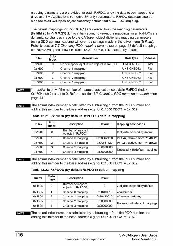
mapping parameters are provided for each RxPDO, allowing data to be mapped to all drive and SM-Applications (Unidrive SP only) parameters. RxPDO data can also be mapped to all CANopen object dictionary entries that allow PDO mapping.
The default mappings for RxPDOA(1) are derived from the mapping parameters (Pr MM.20 to Pr MM.23) during initialisation, however, the mappings for all RxPDOs are dynamic, so changes made to the CANopen object dictionary mapping parameters (using SDO communications) will override settings made in the drive menu (MM.xx). Refer to section 7.7 Changing PDO mapping parameters on page 48 default mappingsfor RxPDOA(1) are shown in Table 12.21. RxPDO1 is enabled by default.
Index Sub-index Description Data type Access
0x1600 0 No of mapped application objects in RxPDO UNSIGNED8 RW0x1600 1 Channel 0 mapping UNSIGNED32 RW*0x1600 2 Channel 1 mapping UNSIGNED32 RW*0x1600 3 Channel 2 mapping UNSIGNED32 RW*0x1600 4 Channel 3 mapping UNSIGNED32 RW*
* - read/write only if the number of mapped application objects in RxPDO (Index 0x160N sub 0) is set to 0. Refer to section 7.7 Changing PDO mapping parameters on page 48.
The actual index number is calculated by subtracting 1 from the PDO number and adding this number to the base address e.g. for 0x1600 PDO3 = 0x1602.
Table 12.21 RxPDOA (by default RxPDO 1 ) default mapping
Index Sub-index Description Default Mapping destination
0x1600 0 Number of mapped objects in RxPDO1 2 2 objects mapped by default
0x1600 1 Channel 0 mapping 0x20062A20 Pr 6.42, derived from Pr MM.200x1600 2 Channel 1 mapping 0x20011520 Pr 1.21, derived from Pr MM.210x1600 3 Channel 2 mapping 0x00000000
Not used with default mappings0x1600 4 Channel 3 mapping 0x00000000
The actual index number is calculated by subtracting 1 from the PDO number and adding this number to the base address e.g. for 0x1600 PDO3 = 0x1602.
Table 12.22 RxPDOD (by default RxPDO 6) default mapping
Index Sub-index Description Default
0x1605 0 Number of mapped objects in RxPDO6 2 2 objects mapped by default
0x1605 1 Channel 0 mapping 0x60400010 controlword0x1605 2 Channel 1 mapping 0x60420010 vl_target_velocity0x1605 3 Channel 2 mapping 0x00000000
Not used with default mappings0x1605 4 Channel 3 mapping 0x00000000
The actual index number is calculated by subtracting 1 from the PDO number and adding this number to the base address e.g. for 0x1600 PDO3 = 0x1602.
NOTE
NOTE
NOTE
NOTE
116 SM-CANopen User Guidewww.controltechniques.com Issue Number: 8

Safety Inform
ationIntroduction
Mechanical
InstallationElectrical
InstallationG
etting Started
EDS Files
Cyclic D
ataN
on-Cyclic
Data
Control and
Status Words
Diagnostics
Advanced Features
CA
Nopen
Reference
Quick
Reference
Glossary O
f Term
sIndex
12.8 TxPDO communication parameters
This section contains the communication parameters for the TxPDOs. SM-CANopen supports a total of 4 TxPDOs. Each PDO has a main index assigned to it, with individual parameters for the PDO accessed using sub-indexes.
All TxPDO configuration parameters are dynamic, i.e. any changes made to these parameters will take effect immediately.
12.8.1 Number of entries
Defines the largest sub-index supported for the specified TxPDO.
Index 0x1800-0x19FFObject code RecordData type PDOCommPar
Table 12.23 Supported TxPDOs (default settings)
TxPDO IndexA 0x1800-0x19FFB 0x1800-0x19FFC 0x1800-0x19FFD 0x1800-0x19FF
The actual index number is calculated by subtracting 1 from the PDO number and adding this number to the base address e.g. for 0x1800 PDO3 = 0x1802.
NOTE
Index 0x1800-0x19FF Sub-index 0 Access RODefault 5 Data type UNSIGNED8
Table 12.24 TxPDO number of entries
TxPDO Index ValueA 0x1800-0x19FF 5B 0x1800-0x19FF 5C 0x1800-0x19FF 5D 0x1800-0x19FF 5
The actual index number is calculated by subtracting 1 from the PDO number and adding this number to the base address e.g. for 0x1600 PDO3 = 0x1602.
NOTE
SM-CANopen User Guide 117Issue Number: 8 www.controltechniques.com

12.8.2 TxPDO COB-ID
The COB-ID is the CAN identifier used by SM-CANopen to transmit TxPDO messages over the CANopen network. The COB-ID is usually calculated using the node address, as this will ensure that the TxPDO COB-ID is unique on the CANopen network.
The upper 3 bits (b31-b29) are used to enable certain functions of the TxPDO.
DSP301 V4.1 specifies default COB-ID values for TxPDO1 to TxPDO4, while all higher TxPDOs must be disabled by default. Default values for the TxPDO COB-IDs are shown in Table 12.26.
12.8.3 TxPDO transmission type
The transmission type defines when the TxPDO data is read from the source parameters and when it is transmitted over the CANopen network. SM-CANopen supports all CANopen transmission modes.
Index 0x1800-0x19FF Sub-index 1Data type UNSIGNED32 Access RW
b31 b30 b29 b28 - b11 b10 - b0PDO
DisableRTR
Disable29-bit ID Enable 00000000000000000 11-bit ID
Table 12.25 PDO COB-ID configuration
Function CommentPDO Disable Set to 1 to disable the TxPDO. SM-CANopen will not transmit the TxPDORTR Disable Set to 1 to disable RTR with the TxPDO.
29-bit ID Enable SM-CANopen hardware does not support 29-bit CAN identifiers so this bit must always be 0.
Table 12.26 TxPDO COB-ID default values
TxPDO Index Default COB-IDA 0x1800-0x19FF 0x00000180 + node addressB 0x1800-0x19FF 0x80000380 + node addressC 0x1800-0x19FF 0x80000000D 0x1800-0x19FF 0x80000000
Index 0x1800-0x19FF Sub-index 2Data type UNSIGNED8 Access RW
Table 12.27 Supported TxPDO transmission types
Transmission type Timing Description
0 Acyclic, synchronous
The source data is read when the SYNC message is received. If the source data has changed, the TxPDO is transmitted.
1 - 240 Cyclic, synchronous
The source data is read and the TxPDO is transmitted every n SYNC messages, where n = transmission type.
252 Synchronous, RTR only
The source data is read when the SYNC message is received, but the TxPDO will only be transmitted when an RTR message is received. The RTR message must have the correct COB-ID for the required TxPDO.
118 SM-CANopen User Guidewww.controltechniques.com Issue Number: 8

Safety Inform
ationIntroduction
Mechanical
InstallationElectrical
InstallationG
etting Started
EDS Files
Cyclic D
ataN
on-Cyclic
Data
Control and
Status Words
Diagnostics
Advanced Features
CA
Nopen
Reference
Quick
Reference
Glossary O
f Term
sIndex
If a TxPDO has transmission type 0 to 240, 254 or 255, the CANopen master controller can use an RTR message (with the COB-ID of the required PDO) to get theSM-CANopen to re-transmit the required TxPDO. SM-CANopen does NOT update the data values for the requested TxPDO; data update will only occur when specified for the TxPDO transmission type.
If a TxPDO is configured with transmission type 252 or 253, it can only be transmitted in response to an RTR message from the CANopen master controller.
Default values for the TxPDO transmission types are shown in Table 12.27.
12.8.4 TxPDO inhibit time
The inhibit time functionality is not implemented in SM-CANopen.
12.8.5 TxPDO event timer
253 Asynchronous, RTR only
The source data is read and the TxPDO is transmitted when an RTR message is received. The RTR message must have the correct COB-ID for the required TxPDO.
254 Asynchronous, event trigger
The source data is read and the TxPDO is transmitted in response to 2 events:1. An OFF-to-ON (0-to-1) transition in Pr MM.36. Pr MM.36 must be reset to OFF for a minimum of 1ms to allow the TxPDO to be transmitted on the next OFF-ON transition. This allows the TxPDO to be controlled by a digital input.2. Event timer. Refer to section 12.8.5 TxPDO event timer on page 119 for more details.
255 Asynchronous, timer trigger
The source data is read and the TxPDO is transmitted in response to the event timer. Refer to section 12.8.5 TxPDO event timer on page 119 for more details.
Please refer to Pr MM.06 on section 5.11 SM-CANopen operating status on page 38 for important information on transmission types.
Table 12.28 TxPDO transmission type default values
TxPDO Index Default CommentA (default = 1) 0x1800-0x19FF 255 Specified in Pr MM.41/SDO configurationB (default = 3) 0x1800-0x19FF 255 SDO configurationC (default = 5) 0x1800-0x19FF 255 SDO configurationD (default = 6) 0x1800-0x19FF 255 SDO configuration
The actual index number is calculated by subtracting 1 from the PDO number and adding this number to the base address e.g. for 0x1800 PDO3 = 0x1802.
Table 12.27 Supported TxPDO transmission types
Transmission type Timing Description
NOTE
NOTE
Index 0x1800-0x19FF Sub-index 3 Access RWDefault 0 Data type USIGN16
Index 0x1800-0x19FF Sub-index 5 Access RWDefault 0 Data type USIGN16
SM-CANopen User Guide 119Issue Number: 8 www.controltechniques.com

The TxPDO event timer specifies the time period (in ms) between transmission of TxPDOs with transmission type 254 or 255 (see section 12.28 TxPDO transmission type default values on page 119). Set the TxPDO event timer to 0 to disable the event timer.
12.9 TxPDO mapping parametersThe source parameters for data transmitted on a TxPDO are specified in the TxPDO mapping parameters. 4 mapping parameters are provided for each TxPDO, allowing data to be mapped to all drive and SM-Applications parameters. TxPDO data can also be mapped to all CANopen object dictionary entries that allow PDO mapping.
The default mappings for TxPDOA are derived from the mapping parameters (Pr MM.10 to Pr MM.13) during initialisation and configured via the menu, therefore changes made via these parameters will require a reset in order to take effect. However, the mappings for all 4 TxPDOs can be changed via the appropriate CANopen object dictionary mapping objects (using SDO communications), changes made via this method will take effect immediately.
The actual index number is calculated by subtracting 1 from the PDO number and adding this number to the base address e.g. for 0x1800 PDO3 = 0x1802.
NOTE
The SM-CANopen will NOT update the drive mapping parameters if the CANopen object dictionary mapping parameters are changed after the SM-CANopen has initialised. This means that the SM-CANopen will revert to the drive parameter-defined mappings during the next initialisation.
Table 12.29 TxPDO mapping parameters
Index Sub-index Description Data type Access
0x1A00-0x1BFF 0 Number of mapped objects in TxPDO UNSIGNED8 RW0x1A00-0x1BFF 1 Channel 0 mapping UNSIGNED32 RW*0x1A00-0x1BFF 2 Channel 1 mapping UNSIGNED32 RW*0x1A00-0x1BFF 3 Channel 2 mapping UNSIGNED32 RW*0x1A00-0x1BFF 4 Channel 3 mapping UNSIGNED32 RW*
* - read/write only if the number of mapped application objects in TxPDO (index 0x1A00 sub-index 0) is set to 0. Refer to section 7.7 Changing PDO mapping parameters on page 48.
The actual index number is calculated by subtracting 1 from the PDO number and adding this number to the base address e.g. for 0x1600 PDO3 = 0x1602.
NOTE
NOTE
120 SM-CANopen User Guidewww.controltechniques.com Issue Number: 8
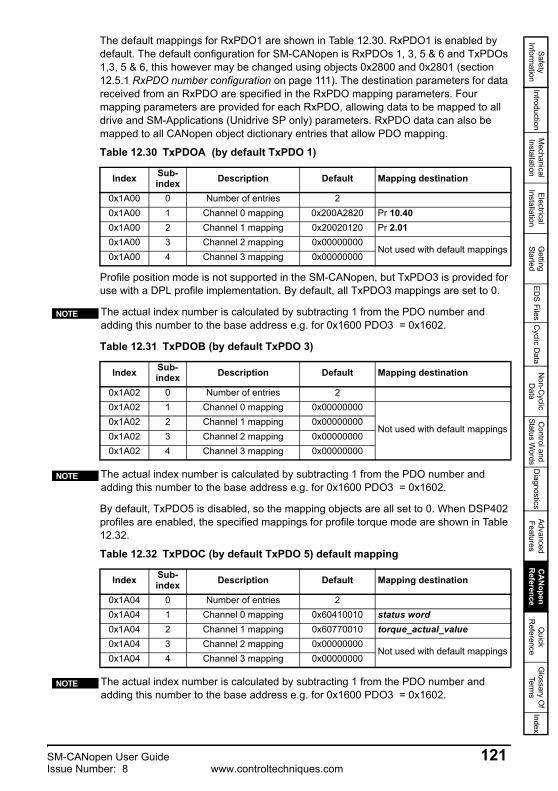
Safety Inform
ationIntroduction
Mechanical
InstallationElectrical
InstallationG
etting Started
EDS Files
Cyclic D
ataN
on-Cyclic
Data
Control and
Status Words
Diagnostics
Advanced Features
CA
Nopen
Reference
Quick
Reference
Glossary O
f Term
sIndex
The default mappings for RxPDO1 are shown in Table 12.30. RxPDO1 is enabled by default. The default configuration for SM-CANopen is RxPDOs 1, 3, 5 & 6 and TxPDOs 1,3, 5 & 6, this however may be changed using objects 0x2800 and 0x2801 (section 12.5.1 RxPDO number configuration on page 111). The destination parameters for data received from an RxPDO are specified in the RxPDO mapping parameters. Fourmapping parameters are provided for each RxPDO, allowing data to be mapped to all drive and SM-Applications (Unidrive SP only) parameters. RxPDO data can also be mapped to all CANopen object dictionary entries that allow PDO mapping.
Profile position mode is not supported in the SM-CANopen, but TxPDO3 is provided for use with a DPL profile implementation. By default, all TxPDO3 mappings are set to 0.
By default, TxPDO5 is disabled, so the mapping objects are all set to 0. When DSP402 profiles are enabled, the specified mappings for profile torque mode are shown in Table 12.32.
Table 12.30 TxPDOA (by default TxPDO 1)
Index Sub-index Description Default Mapping destination
0x1A00 0 Number of entries 20x1A00 1 Channel 0 mapping 0x200A2820 Pr 10.400x1A00 2 Channel 1 mapping 0x20020120 Pr 2.010x1A00 3 Channel 2 mapping 0x00000000
Not used with default mappings0x1A00 4 Channel 3 mapping 0x00000000
The actual index number is calculated by subtracting 1 from the PDO number and adding this number to the base address e.g. for 0x1600 PDO3 = 0x1602.
Table 12.31 TxPDOB (by default TxPDO 3)
Index Sub-index Description Default Mapping destination
0x1A02 0 Number of entries 20x1A02 1 Channel 0 mapping 0x00000000
Not used with default mappings0x1A02 2 Channel 1 mapping 0x000000000x1A02 3 Channel 2 mapping 0x000000000x1A02 4 Channel 3 mapping 0x00000000
The actual index number is calculated by subtracting 1 from the PDO number and adding this number to the base address e.g. for 0x1600 PDO3 = 0x1602.
Table 12.32 TxPDOC (by default TxPDO 5) default mapping
Index Sub-index Description Default Mapping destination
0x1A04 0 Number of entries 20x1A04 1 Channel 0 mapping 0x60410010 status word0x1A04 2 Channel 1 mapping 0x60770010 torque_actual_value0x1A04 3 Channel 2 mapping 0x00000000
Not used with default mappings0x1A04 4 Channel 3 mapping 0x00000000
The actual index number is calculated by subtracting 1 from the PDO number and adding this number to the base address e.g. for 0x1600 PDO3 = 0x1602.
NOTE
NOTE
NOTE
SM-CANopen User Guide 121Issue Number: 8 www.controltechniques.com
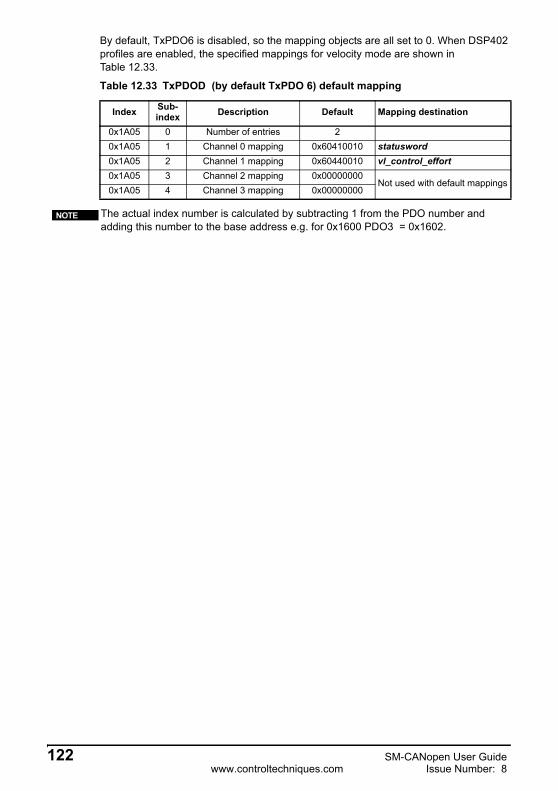
By default, TxPDO6 is disabled, so the mapping objects are all set to 0. When DSP402 profiles are enabled, the specified mappings for velocity mode are shown inTable 12.33.
Table 12.33 TxPDOD (by default TxPDO 6) default mapping
Index Sub-index Description Default Mapping destination
0x1A05 0 Number of entries 20x1A05 1 Channel 0 mapping 0x60410010 statusword0x1A05 2 Channel 1 mapping 0x60440010 vl_control_effort0x1A05 3 Channel 2 mapping 0x00000000
Not used with default mappings0x1A05 4 Channel 3 mapping 0x00000000
The actual index number is calculated by subtracting 1 from the PDO number and adding this number to the base address e.g. for 0x1600 PDO3 = 0x1602.
NOTE
122 SM-CANopen User Guidewww.controltechniques.com Issue Number: 8
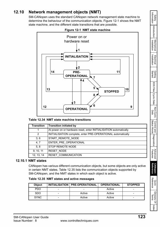
Safety Inform
ationIntroduction
Mechanical
InstallationElectrical
InstallationG
etting Started
EDS Files
Cyclic D
ataN
on-Cyclic
Data
Control and
Status Words
Diagnostics
Advanced Features
CA
Nopen
Reference
Quick
Reference
Glossary O
f Term
sIndex
12.10 Network management objects (NMT)SM-CANopen uses the standard CANopen network management state machine to determine the behaviour of the communication objects. Figure 12-1 shows the NMT state machine, and the different state transitions that are possible.
Figure 12-1 NMT state machine
12.10.1 NMT statesCANopen has various different communication objects, but some objects are only active in certain NMT states. Table 12.35 lists the communication objects supported by SM-CANopen, and the NMT states in which each object is active.
Table 12.34 NMT state machine transitions
Transition Transition initiated by1 At power on or hardware reset, enter INITIALISATION automatically2 INITIALISATION complete, enter PRE-OPERATIONAL automatically
3, 6 START_REMOTE_NODE4, 7 ENTER_PRE_OPERATIONAL5, 8 STOP REMOTE NODE
9, 10, 11 RESET_NODE12, 13, 14 RESET_COMMUNICATION
INITIALISATION
214
7
PRE-OPERATIONAL
STOPPED
OPERATIONAL
1
3
13
12
11
10
9
5
8
6
4
Power on orhardware reset
Table 12.35 NMT states and active messages
Object INITIALISATION PRE-OPERATIONAL OPERATIONAL STOPPEDPDO - - Active -SDO - Active Active -
SYNC - Active Active -
SM-CANopen User Guide 123Issue Number: 8 www.controltechniques.com

12.10.2 InitialisationSM-CANopen may be switched into Initialisation from any other state using the RESET_NODE or RESET_COMMUNICATION commands.
12.10.3 Pre-operationalThe synchronisation object, emergency object, NMT objects and SDO communications are all active in the PRE-OPERATIONAL state, allowing device configuration to take place. PDOs do not exist in the PRE-OPERATIONAL state and are inactive. This allows PDO configuration and mapping objects to be configured without interfering with active communications.
SM-CANopen may be switched into PRE-OPERATIONAL from OPERATIONAL (transition 4) or STOPPED (transition 7) using the ENTER_PRE-OPERATIONAL command.
12.10.4 OperationalAll communication objects are active in the OPERATIONAL state. All configured PDOs are created when SM-CANopen enters the OPERATIONAL state, using the parameter values in the object dictionary. SDO communications remain active in the OPERATIONAL state.
SM-CANopen may be switched into OPERATIONAL from PRE-OPERATIONAL (transition 3) or STOPPED (transition 6) using the START_REMOTE-NODE command.
12.10.5 StoppedAll communications (except NMT and heartbeat) are stopped when the SM-CANopen is switched into the STOPPED state. SM-CANopen will only respond to NMT messages while in the STOPPED state, so it must be switched into the PRE-OPERATIONAL or OPERATIONAL state to re-start communications. The heartbeat error control protocol remains active during the STOPPED state.
SM-CANopen may be switched into STOPPED from PRE-OPERATIONAL (transition 5) or OPERATIONAL (transition 8) using the STOP_REMOTE_NODE command.
12.11 NMT commandsNetwork Management (NMT) commands are low-level CANopen commands that are used to switch SM-CANopen between the different NMT states. NMT messages always have a CAN identifier of 0x000 and contain 2 data bytes.
Emergency - Active Active -Boot-up Active - - -
NMT Active Active Active
Table 12.35 NMT states and active messages
Object INITIALISATION PRE-OPERATIONAL OPERATIONAL STOPPED
Table 12.36 NMT message structure
CAN identifier Command (See Table 12.37) Node ID
0x000 See Table 12.37 Target node
124 SM-CANopen User Guidewww.controltechniques.com Issue Number: 8

Safety Inform
ationIntroduction
Mechanical
InstallationElectrical
InstallationG
etting Started
EDS Files
Cyclic D
ataN
on-Cyclic
Data
Control and
Status Words
Diagnostics
Advanced Features
CA
Nopen
Reference
Quick
Reference
Glossary O
f Term
sIndex
12.12 Layer setting services (LSS)SM-CANopen supports the complete CANopen Layer Setting Service protocol, as defined in DSP205 V1.1. LSS provides the ability for a CANopen device with LSS Master capabilities to enquire and change the settings of certain parameters of the local layers on a LSS Slave CANopen device via the CAN network.
The following parameters can be enquired and/or changed by the use of LSS:
• Node-ID of the CANopen slave
• Bit timing parameters of the physical layer (baud rate)
• LSS address (Identity Object, Index 0x1018). The LSS address consists of Vendor ID, Product Code, Revision Number and Serial Number, and is unique to every SM-CANopen.
12.12.1 Enabling LSSLSS functionality is enabled automatically if SM-CANopen initialises without an active node address, or when an NMT Stop command is issued. In default configuration,SM-CANopen will have LSS enabled. There is no NMT functionality when LSS is active.
When LSS is active, all CANopen devices will receive LSS commands on COB-ID 2021 (0x07E5) and respond on COB-ID 2020 (0x07E4). All LSS messages are 8 bytes long.
12.12.2 Configuring SM-CANopen via LSSWhen SM-CANopen enters LSS mode, it is in an “operational” state, and no configuration can take place. SM-CANopen must be switched into “configuration” by:
1. addressing an SM-CANopen using its complete (and unique) LSS address.
2. switching all LSS devices into the “configuration” state.
Switching “all” devices into the “configuration” state should only be used when there is a single node on the network in LSS mode, or a bit timing change is required. This can be used for adding a single node at a time to the network without knowing its LSS address, configuring and activating it before adding another new device.
12.12.3 Switch mode globalThe switch mode global command is used to change the LSS state of all nodes currently in LSS.
Mode 0 - switches all devices into “operational” mode.
Mode 1 - switches all devices into “configuration” mode.
Table 12.37 NMT commands
Command CodeSTART_REMOTE_NODE 1STOP_REMOTE_NODE 2
ENTER_PRE_OPERTATIONAL 128RESET_NODE 129
RESET_COMMUNICATION 130
Table 12.38 Global Modes
COB-IDByte
0 1 2 - 70x7E5 0x04 Mode Reserved (set to 0)
SM-CANopen User Guide 125Issue Number: 8 www.controltechniques.com
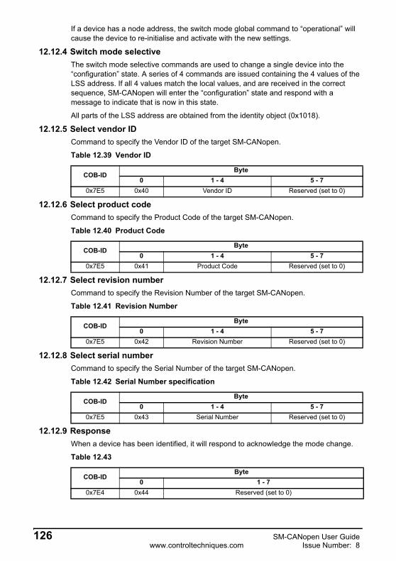
If a device has a node address, the switch mode global command to “operational” will cause the device to re-initialise and activate with the new settings.
12.12.4 Switch mode selectiveThe switch mode selective commands are used to change a single device into the “configuration” state. A series of 4 commands are issued containing the 4 values of the LSS address. If all 4 values match the local values, and are received in the correct sequence, SM-CANopen will enter the “configuration” state and respond with a message to indicate that is now in this state.
All parts of the LSS address are obtained from the identity object (0x1018).
12.12.5 Select vendor IDCommand to specify the Vendor ID of the target SM-CANopen.
12.12.6 Select product codeCommand to specify the Product Code of the target SM-CANopen.
12.12.7 Select revision numberCommand to specify the Revision Number of the target SM-CANopen.
12.12.8 Select serial numberCommand to specify the Serial Number of the target SM-CANopen.
12.12.9 ResponseWhen a device has been identified, it will respond to acknowledge the mode change.
Table 12.39 Vendor ID
COB-IDByte
0 1 - 4 5 - 70x7E5 0x40 Vendor ID Reserved (set to 0)
Table 12.40 Product Code
COB-IDByte
0 1 - 4 5 - 70x7E5 0x41 Product Code Reserved (set to 0)
Table 12.41 Revision Number
COB-IDByte
0 1 - 4 5 - 70x7E5 0x42 Revision Number Reserved (set to 0)
Table 12.42 Serial Number specification
COB-IDByte
0 1 - 4 5 - 70x7E5 0x43 Serial Number Reserved (set to 0)
Table 12.43
COB-IDByte
0 1 - 70x7E4 0x44 Reserved (set to 0)
126 SM-CANopen User Guidewww.controltechniques.com Issue Number: 8
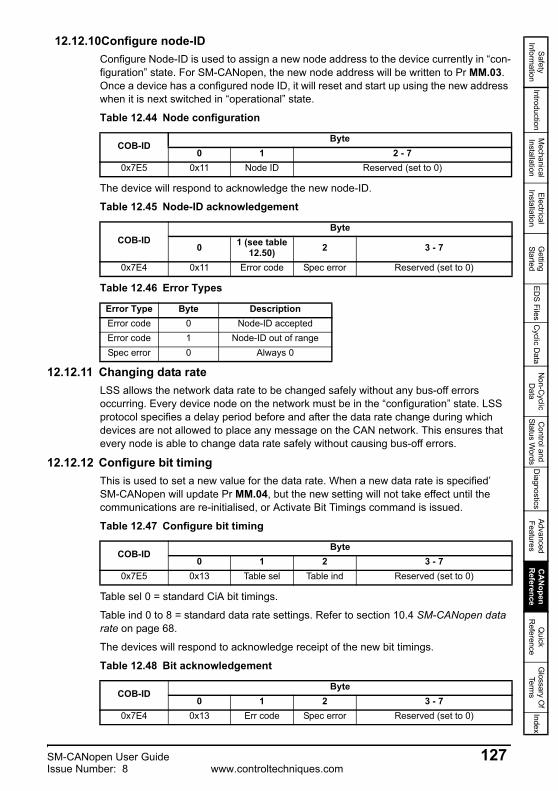
Safety Inform
ationIntroduction
Mechanical
InstallationElectrical
InstallationG
etting Started
EDS Files
Cyclic D
ataN
on-Cyclic
Data
Control and
Status Words
Diagnostics
Advanced Features
CA
Nopen
Reference
Quick
Reference
Glossary O
f Term
sIndex
12.12.10Configure node-IDConfigure Node-ID is used to assign a new node address to the device currently in “con-figuration” state. For SM-CANopen, the new node address will be written to Pr MM.03. Once a device has a configured node ID, it will reset and start up using the new address when it is next switched in “operational” state.
The device will respond to acknowledge the new node-ID.
12.12.11 Changing data rateLSS allows the network data rate to be changed safely without any bus-off errors occurring. Every device node on the network must be in the “configuration” state. LSS protocol specifies a delay period before and after the data rate change during which devices are not allowed to place any message on the CAN network. This ensures that every node is able to change data rate safely without causing bus-off errors.
12.12.12 Configure bit timingThis is used to set a new value for the data rate. When a new data rate is specified’SM-CANopen will update Pr MM.04, but the new setting will not take effect until the communications are re-initialised, or Activate Bit Timings command is issued.
Table sel 0 = standard CiA bit timings.
Table ind 0 to 8 = standard data rate settings. Refer to section 10.4 SM-CANopen data rate on page 68.
The devices will respond to acknowledge receipt of the new bit timings.
Table 12.44 Node configuration
COB-IDByte
0 1 2 - 70x7E5 0x11 Node ID Reserved (set to 0)
Table 12.45 Node-ID acknowledgement
COB-IDByte
0 1 (see table 12.50) 2 3 - 7
0x7E4 0x11 Error code Spec error Reserved (set to 0)
Table 12.46 Error Types
Error Type Byte DescriptionError code 0 Node-ID acceptedError code 1 Node-ID out of rangeSpec error 0 Always 0
Table 12.47 Configure bit timing
COB-IDByte
0 1 2 3 - 70x7E5 0x13 Table sel Table ind Reserved (set to 0)
Table 12.48 Bit acknowledgement
COB-IDByte
0 1 2 3 - 70x7E4 0x13 Err code Spec error Reserved (set to 0)
SM-CANopen User Guide 127Issue Number: 8 www.controltechniques.com
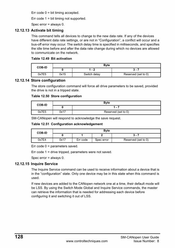
Err code 0 = bit timing accepted.
Err code 1 = bit timing not supported.
Spec error = always 0.
12.12.13 Activate bit timingThis command tells all devices to change to the new data rate. If any of the devices have different data rate settings, or are not in “Configuration”, a conflict will occur and a bus-off error may occur. The switch delay time is specified in milliseconds, and specifies the idle time before and after the data rate change during which no devices are allowed to communicate on the network.
12.12.14 Store configurationThe store configuration command will force all drive parameters to be saved, provided the drive is not in a tripped state.
SM-CANopen will respond to acknowledge the save request.
Err code 0 = parameters saved.
Err code 1 = drive tripped, parameters were not saved.
Spec error = always 0.
12.12.15 Inquire ServiceThe Inquire Service command can be used to receive information about a device that is in the “configuration” state. Only one device may be in this state when this command is used.
If new devices are added to the CANopen network one at a time, their default mode will be LSS. By using the Switch Mode Global and Inquire Service commands, the master can retrieve the information that is needed for addressing each device before configuring it and switching it out of LSS.
Table 12.49 Bit activation
COB-IDByte
0 1 - 2 3 - 70x7E5 0x15 Switch delay Reserved (set to 0)
Table 12.50 Store configuration
COB-IDByte
0 1 - 70x7E5 0x17 Reserved (set to 0)
Table 12.51 Configuration acknowledgement
COB-IDByte
0 1 2 3 - 70x7E4 0x17 Err code Spec error Reserved (set to 0)
128 SM-CANopen User Guidewww.controltechniques.com Issue Number: 8

Safety Inform
ationIntroduction
Mechanical
InstallationElectrical
InstallationG
etting Started
EDS Files
Cyclic D
ataN
on-Cyclic
Data
Control and
Status Words
Diagnostics
Advanced Features
CA
Nopen
Reference
Quick
Reference
Glossary O
f Term
sIndex
12.12.16 Inquire vendor IDRequest message
Response message
12.12.17 Inquire product codeRequest message
Response message
12.12.18 Inquire revision numberRequest message
Response message
12.12.19 Inquire serial numberRequest message
Table 12.52 Request message
COB-IDByte
0 1 - 70x7E5 0x5A Reserved (set to 0)
Table 12.53 Response message
COB-IDByte
0 1 - 4 5 - 70x7E4 0x5A Vendor ID Reserved (set to 0)
Table 12.54 Request message
COB-IDByte
0 1 - 70x7E5 0x5B Reserved (set to 0)
Table 12.55 Response message
COB-IDByte
0 1 - 4 5 - 70x7E4 0x5B Product Code Reserved (set to 0)
Table 12.56 Request message
COB-IDByte
0 1 - 70x7E5 0x5C Reserved (set to 0)
Table 12.57 Response message
COB-IDByte
0 1 - 4 5 - 70x7E4 0x40 Revision Number Reserved (set to 0)
Table 12.58 Request message
COB-IDByte
0 1 - 70x7E5 0x5D Reserved (set to 0)
SM-CANopen User Guide 129Issue Number: 8 www.controltechniques.com
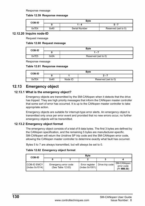
Response message
12.12.20 Inquire node-IDRequest message
Response message
12.13 Emergency object12.13.1 What is the emergency object?
Emergency objects are transmitted by the SM-CANopen when it detects that the drive has tripped. They are high priority messages that inform the CANopen master controller that some sort of error has occurred. It is up to the CANopen master controller to take appropriate action.
Emergency objects are suitable for interrupt-type error alerts. An emergency object is transmitted only once per error event and provided that no new errors occur, no further emergency objects will be transmitted.
12.13.2 Emergency object formatThe emergency object consists of a total of 8 data bytes. The first 3 bytes are defined by the CANopen specification, and the remaining 5 bytes are manufacturer-specific.SM-CANopen will return the Unidrive SP trip code and the SM-CANopen error code, allowing the CANopen master controller to determine exactly what fault has occurred.
Table 12.59 Response message
COB-IDByte
0 1 - 4 5 - 70x7E4 0x40 Serial Number Reserved (set to 0)
Table 12.60 Request message
COB-IDByte
0 1 - 70x7E5 0x5A Reserved (set to 0)
Table 12.61 Response message
COB-IDByte
0 1 2 - 70x7E4 0x40 Node ID Reserved (set to 0)
Bytes 5 to 7 are always transmitted, but will always be set to 0.
Table 12.62 Emergency object format
COB-IDByte
0 1 2 3 4
COB-ID EMCY(Index 0x1014)
Emergency error code(See Table 12.63)
Error register (Index 0x1001)
Drive trip code SM-CANopen error code(Pr MM.50)
130 SM-CANopen User Guidewww.controltechniques.com Issue Number: 8

Safety Inform
ationIntroduction
Mechanical
InstallationElectrical
InstallationG
etting Started
EDS Files
Cyclic D
ataN
on-Cyclic
Data
Control and
Status Words
Diagnostics
Advanced Features
CA
Nopen
Reference
Quick
Reference
Glossary O
f Term
sIndex
The CANopen specification defines a list of standard error codes. Supported CANopen emergency error codes (and the drive trips that will produce the emergency error code) are listed in Table 12.63. All other drive trips will produce the generic error code, 0x1000.
For full details about each trip, refer to the drive documentation.
12.14 Emergency object stateThe SM-CANopen may be in one of two emergency states, as shown in Figure 12-2 on page 131.
Figure 12-2 Emergency object states
Table 12.63 Emergency error codes
Emergency error code
Drive trip codes Description
0x0000 ---- Error reset or no error.
0x1000 All other trip codes Generic error.
0x230020, 43,
111-118, 141-148
Current. This error will occur if any type of over-current error is detected in the output stage(s) of the drive.
0x3000 8 Voltage. This error will occur if the drive external +10V reference voltage is short-circuit.
0x3100 32 Voltage, main supply. This error will occur if a problem is detected with the main supply voltage to the drive.
0x3200 1, 2, 5, 9, 131-138
Voltage, internal. This error will occur if any problem is detected with the internal voltages in the drive.
0x4200 21-23, 27, 121-128
Temperature. This error will occur if any over-temperature problem is detected on the drive.
0x5000 220-229 Hardware fault. This error will occur if the drive fails due to internal problems, indicated by an “HF” trip.
Error free
Error occurred
0
1 4
2
3
SM-CANopen User Guide 131Issue Number: 8 www.controltechniques.com

12.14.1 Error registerThe error register is used by the SM-CANopen to indicate that an error has occurred, and can be mapped to TxPDOs if required. If a bit is set to 1, the specified error has occurred.
12.14.2 Generating emergency objects from DPL Emergency objects are now supported from DPL. This allows an error code to be written to a DPL variable to produce an emergency object message on the network. To use this feature an object association needs to be made to object 0x1001 sub-index 0. This should be a 32 bit read-only object. To send a new emergency message the error code must be specified in the lower 16 bits (bytes 0 and 1) of this object. Byte 2 will be a logical “OR” with the error register byte created in the modules emergency message handler, and byte 3 can be used to set the 3rd of the manufacturer specific bytes of the emergency object. The modules emergency handler checks this association and manages it accordingly, therefore if an error is produced by the host drive, then by the module itself, both errors must be cleared in order to transmit the all-clear empty emergency object.
Table 12.64 Emergency object state transitions
Transition Reference Description
0 Initialisation After initialisation, SM-CANopen enters the error free state if no error is detected. The emergency object is not transmitted.
1 Error occurred SM-CANopen detects an error, transmits the emergency object once, and enters the error state.
2 Reset, new error occurred
One error (but not all errors) have been cleared. SM-CANopen will transmit another emergency object with information about the remaining error.
3 New error occurred
SM-CANopen has detected a new error condition, while in the error state. SM-CANopen remains in error state and transmits another emergency object with the appropriate error codes.
4 Reset, error cleared
All errors have been cleared. SM-CANopen will return to the error free state, and transmit an emergency object with the emergency error code set to 0x0000.
Table 12.65 Error register
Bit Error Description0 Generic error Set if any other bits in the register are set.1 Current Set if current errors occur (10.09/10.17 - SP)2 Voltage When drive detects a UU error.3 Temperature Set if temperature errors occur (10.18 - SP)4 Communication error
Always set to 05 Device profile specific6 Reserved7 Manufacturer specific Set if Pr 10.19 is set.
Please refer to Chapter 11.12.1 DPL function call on page 82 for more information.NOTE
132 SM-CANopen User Guidewww.controltechniques.com Issue Number: 8

Safety Inform
ationIntroduction
Mechanical
InstallationElectrical
InstallationG
etting Started
EDS Files
Cyclic D
ataN
on-Cyclic
Data
Control and
Status Words
Diagnostics
Advanced Features
CA
Nopen
Reference
Quick
Reference
Glossary O
f Term
sIndex
12.15 Unidrive SP and Commander SK: device profilesBasic implementations of two DSP402 device profiles (profile torque and velocity) have been included in the SM-CANopen, and supported objects are detailed in this section. Additional features may be implemented in an SM-Applications DPL program on (Unidrive SP only).
12.15.1 Enable DSP402 device profiles
Set DSP402 device profile enable (Pr MM.37) to ON to enable the device profiles and select the required profile using modes_of_operation (see section 12.15.13 Modes of operation on page 142).
Refer to section 11.13 Unidrive SP: SM-Applications object priority on page 84 to ensure that the correct object implementations will be accessed. If a device profile is written entirely in the SM-Applications DPL program, it is recommended that the internal SM-CANopen profiles should be disabled.
12.15.2 Conversion factorsThe velocity mode profile specifies velocity parameters in rpm or percent, time parameters in seconds, and ramps in rpm/second. The drive uses different units for the different types of parameter, so conversion factors must be used.
Hz/rpm functionsThe Hz/rpm functions are used when the drive is in open loop mode, as all speed reference parameters within the drive have units of Hz. The number of motor pole pairs is read from the drive whenever these equations are used.
Hz = rpm*PolePairs/60rpm = Hz*60/PolePairs
Ramp conversion functionsThe ramp conversion functions are used to convert between rpm/s (specified using DeltaSpeed and DeltaTime) and the ramp specification used by the drive.
In open loop and SE mode, drive ramp units are specified in s/100Hz.
Secs/100Hz = DeltaTime*(100*6/PolePairs)*100/DeltaSpeedIn closed loop and servo modes, drive ramp units are specified in s/1000rpm.
Secs/1000rpm = DeltaTime*1000*1000/DeltaSpeed
12.15.3 Parameter data object mappingThe controlword and statusword used by the device profile modes are not the standard drive control and status words. They are defined in CiA DSP-402 V1.1, “Device Profile for Drive and Motion Control”.
Table 12.66 Enable DSP402
Name DSP402 device profile enable
Pr MM.37Default OFF (0)Range OFF (0) or ON (1)Access RW
Cyclic data compression (Pr MM.34) MUST be enabled and the data format (Pr MM.05) must be set to 0 to use the DSP402 device profiles (see section 11.8 Cyclic data compression on page 80 and section 5-10 SDO Configuration on page 35).
SM-CANopen User Guide 133Issue Number: 8 www.controltechniques.com

12.15.4 Profile torque modeWhen the profile torque mode is selected, RxPDO5 and TxPDO5 consist of two 16-bit words. The specified mappings for profile torque mode are shown in Table 12.67.
12.15.5 Velocity modeWhen the velocity mode profile is selected, RxPDO6 and TxPDO6 consists of two 16-bit words. The specified mappings for velocity mode are shown in Table 12.68.
12.15.6 Common entriesThe common objects may be used by all supported profiles.
12.15.7 Error code
The error_code captures the code of the last error that occurred in the drive. It corresponds to the value of the low 16 bits of object 0x1003, pre_defined_error_field.
Table 12.67 PDO5 mapping
Data word Mapped object Mapping statusRxPDO5 Word 0 0x6040 controlwordRxPDO5 Word 1 0x6071 target_torqueTxPDO5 Word 0 0x6041 statuswordTxPDO5 Word 1 0x6077 torque_actual_value
Table 12.68 PDO6 mapping
Data word Mapped object Mapping statusRxPDO6 Word 0 0x6040 controlwordRxPDO6 Word 1 0x6042 vl_target_velocityTxPDO6 Word 0 0x6041 statuswordTxPDO6 Word 1 0x6044 vl_control_effort
Table 12.69 Supported common objects
Index Object Name Type Access PDO mapping
0x603F VAR error_code UNSIGNED16 RO Yes0x6502 VAR supported_drive_modes UNSIGNED32 RO Yes
Table 12.70 error_code
Index 0x603F Object code VAR Access ROSub-index 0 Data type UNSIGNED16 PDO mapping YesDefault N/A Units None
134 SM-CANopen User Guidewww.controltechniques.com Issue Number: 8
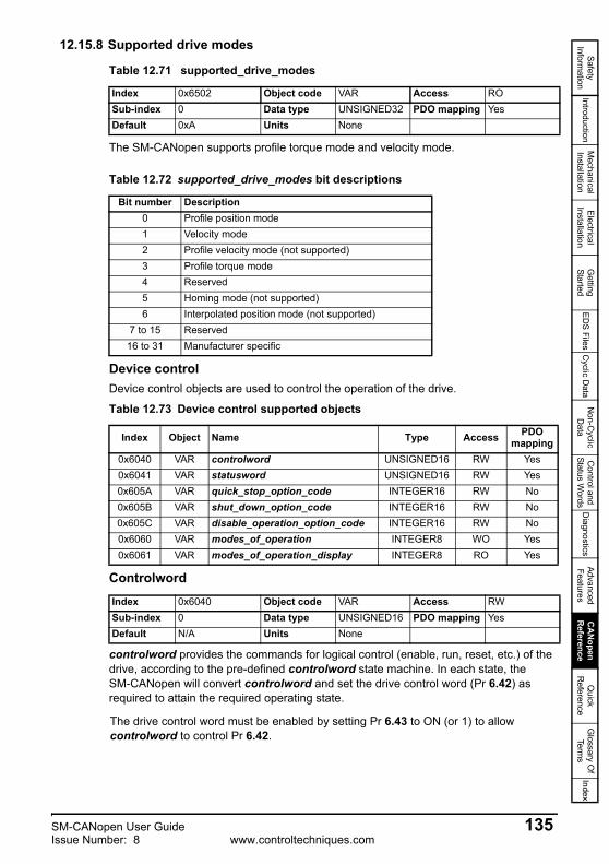
Safety Inform
ationIntroduction
Mechanical
InstallationElectrical
InstallationG
etting Started
EDS Files
Cyclic D
ataN
on-Cyclic
Data
Control and
Status Words
Diagnostics
Advanced Features
CA
Nopen
Reference
Quick
Reference
Glossary O
f Term
sIndex
12.15.8 Supported drive modes
The SM-CANopen supports profile torque mode and velocity mode.
Device controlDevice control objects are used to control the operation of the drive.
Controlword
controlword provides the commands for logical control (enable, run, reset, etc.) of the drive, according to the pre-defined controlword state machine. In each state, theSM-CANopen will convert controlword and set the drive control word (Pr 6.42) as required to attain the required operating state.
Table 12.71 supported_drive_modes
Index 0x6502 Object code VAR Access ROSub-index 0 Data type UNSIGNED32 PDO mapping YesDefault 0xA Units None
Table 12.72 supported_drive_modes bit descriptions
Bit number Description0 Profile position mode1 Velocity mode2 Profile velocity mode (not supported)3 Profile torque mode4 Reserved5 Homing mode (not supported)6 Interpolated position mode (not supported)
7 to 15 Reserved16 to 31 Manufacturer specific
Table 12.73 Device control supported objects
Index Object Name Type Access PDO mapping
0x6040 VAR controlword UNSIGNED16 RW Yes0x6041 VAR statusword UNSIGNED16 RW Yes0x605A VAR quick_stop_option_code INTEGER16 RW No0x605B VAR shut_down_option_code INTEGER16 RW No0x605C VAR disable_operation_option_code INTEGER16 RW No0x6060 VAR modes_of_operation INTEGER8 WO Yes0x6061 VAR modes_of_operation_display INTEGER8 RO Yes
Index 0x6040 Object code VAR Access RWSub-index 0 Data type UNSIGNED16 PDO mapping YesDefault N/A Units None
The drive control word must be enabled by setting Pr 6.43 to ON (or 1) to allow controlword to control Pr 6.42.
SM-CANopen User Guide 135Issue Number: 8 www.controltechniques.com

7 device commands are used to switch between different control states, and these are listed in.Table 12.75.
States may be changed using the controlword and/or internal events. The current state can be read using the statusword.
Table 12.74 Controlword bit descriptions
Bit Name Description0 SWITCH ON
Used (with controlword b7) to control the operating state of the device profile.
1 DISABLE VOLTAGE2 QUICK STOP3 ENABLE OPERATION4
Operation mode specific Not used by SM-CANopen5
6
7 FAULT RESET Used (with controlword b0-b3) to control the operating state of the device profile.
8-10 Reserved Reserved
11 AUTO
Set to 1 to enable controlword control of the drive. AUTO directly controls the AUTO bit (b7) of Pr 6.42. Refer to Unidrive SP Advanced User Guide for more details about Pr 6.42.
12-15 Manufacturer specific Not used by SM-CANopen
Table 12.75 Example control words
Command FAULT RESET
ENABLE OPERATION
QUICK STOP
DISABLE VOLTAGE
SWITCH ON
Transitions affected
Shutdown 0 X 1 1 0 2, 6, 8Switch on 0 X 1 1 1 3
Disable voltage 0 X X 0 X 7, 9, 10, 12Quick stop 0 X 0 1 X 7, 10, 11
Disable operation 0 0 1 1 1 5Enable operation 0 1 1 1 1 4, 16
Fault reset 0-1 X X X X 15
136 SM-CANopen User Guidewww.controltechniques.com Issue Number: 8
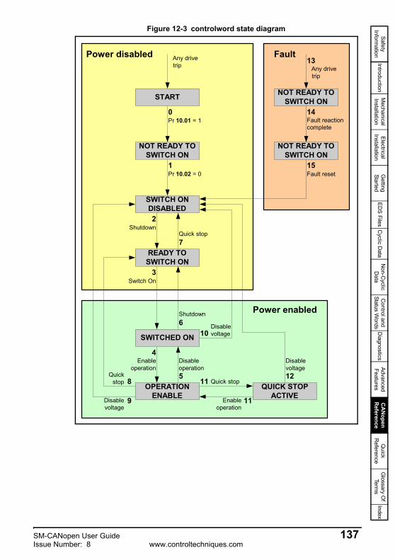
Safety Inform
ationIntroduction
Mechanical
InstallationElectrical
InstallationG
etting Started
EDS Files
Cyclic D
ataN
on-Cyclic
Data
Control and
Status Words
Diagnostics
Advanced Features
CA
Nopen
Reference
Quick
Reference
Glossary O
f Term
sIndex
Figure 12-3 controlword state diagram
SWITCH ONDISABLED
NOT READY TOSWITCH ON
START
READY TOSWITCH ON
SWITCHED ON
OPERATIONENABLE
QUICK STOPACTIVE
NOT READY TOSWITCH ON
NOT READY TOSWITCH ON
Pr 10.01 = 1
Pr 10.02 = 0
0
Shutdown
1
2
Switch On3
Enableoperation
4Disableoperation5
Shutdown6
Quick stop7
Quickstop 8
9Disablevoltage
10Disablevoltage
11 Quick stop
Disablevoltage12
Any drivetrip
13
Fault reactioncomplete
14
Fault reset15
11Enableoperation
Any drivetrip
Power enabled
FaultPower disabled
SM-CANopen User Guide 137Issue Number: 8 www.controltechniques.com

State transitions are caused by internal events in the drive or by commands received from the host via the controlword (refer to Figure 12-3 controlword state diagram on page 137).
If a command is received which causes a change of state, this command must be processed completely and the new state attained before the next command can be processed.
Table 12.76 State transitions for profile control
State transition Event Action
0 Pr 10.01 = 1 Drive must not be tripped when controlword initialises.
1 Pr 10.02 = 0 Drive must be disabled when controlword initialises.
2 controlword = “Shutdown” Specified ramp mode selected in drive.
3 controlword = “Switch on”Select decel ramp 1, Pr 2.20 = 1Set decel ramp rate, Pr 2.21 as requiredSet Pr 6.42 bit 0 to 1.
4 controlword = “Enable operation”Select decel ramp 1, Pr 2.20 = 1Set decel ramp rate, Pr 2.21 as requiredSet Pr 6.42 bit 1 to 1.
5 controlword = “Disable operation” Specified ramps selected in driveReset Pr 6.42 bit 1 to 0.
6 controlword = “Shutdown” Specified ramps selected in driveReset Pr 6.42 bit 1 to 0.
7 controlword = “Quick stop” Move to Switch On Disabled.
8 controlword = “Shutdown” Specified ramps selected in driveReset Pr 6.42 bit 0 and bit 1 to 0.
9 controlword = “Disable voltage” Reset Pr 6.42 bit 0 and bit 1 to 0.
10 controlword = “Disable voltage” or “Quick stop”
Specified ramps selected in driveReset Pr 6.42 bit 0 to 0.
11 controlword = “Quick stop” Specified ramps selected in driveReset Pr 6.42 bit 1 to 0.
12 Quick stop complete or control-word = “Disable voltage” Reset Pr 6.42 bit 0 to 0.
13 Pr 10.01 = 1 drive trip.14 Fault reaction complete Reset Pr 6.42 bit 0 and bit 1 to 0.15 controlword = “Fault reset” Specified ramps selected in drive.
16 controlword = “Enable operation” Specified ramps selected in driveReset Pr 6.42 bit 1 to 1.
State transition 16 is only available if the quick_stop_option_code is set to 5, 6, 7 or 8. Specified ramps are defined by shutdown_option_code, quick_stop_option_code and disable_operation_option_code.
NOTE
138 SM-CANopen User Guidewww.controltechniques.com Issue Number: 8

Safety Inform
ationIntroduction
Mechanical
InstallationElectrical
InstallationG
etting Started
EDS Files
Cyclic D
ataN
on-Cyclic
Data
Control and
Status Words
Diagnostics
Advanced Features
CA
Nopen
Reference
Quick
Reference
Glossary O
f Term
sIndex
12.15.9 Statusword
The statusword indicates the current status of the drive. The statusword bits are defined in the Table 12.77.
Table 12.78 shows the values of statusword in each state. Bits marked X are irrelevant for that state, and other combinations are not allowed.
Index 0x6041 Object code VAR Access ROSub-index 0 Data type UNSIGNED16 PDO mapping YesDefault N/A Units None
Table 12.77 statusword bit descriptions
Bit Name Source0 READY TO SWITCH ON
Controlled by the device control state machine (see Figure 12.78 on page 139).
1 SWITCHED ON2 OPERATION ENABLED3 FAULT
4 VOLTAGE DISABLEDVOLTAGE_DISABLED will be set to 1 when SM-CANopen is responding to the “Disable voltage“ command in the controlword.
5 QUICK STOP Controlled by the device control state machine (see Figure 12.78 on page 139).6 SWITCH ON DISABLED
7 Reserved8 Reserved
9 REMOTEIndicates that the drive is being controlled bycontrolword. Set to 1 if both control word enable (Pr 6.43) and AUTO bit (Pr 6.42 bit 7) are set to 1.
10 TARGETIndicates the “At Speed” indication (Pr 10.06) from the drive. When quick stop is active, TARGET returns the “Drive Running” bit. (Pr 10.02).
11 INTERNAL LIMIT ACTIVE Set if vl_velocity_demand goes outside the limits specified in vl_velocity_min_max_amount.
12-15 Reserved
Table 12.78 statusword value
State SWITCH ON DISABLED
QUICK STOP FAULT OPERATION
ENABLEDSWITCHED
ONREADY TO SWITCH ON
NOT READY TO SWITCH ON 0 X 0 0 0 0
SWITCH ON DISABLED 1 X 0 0 0 0
READY TO SWITCH ON 0 1 0 0 0 1
SWITCHED ON 0 1 0 0 1 1OPERATION ENABLED 0 1 0 1 1 1
FAULT 0 X 1 1 1 1FAULT REACTION ACTIVE 0 X 1 1 1 1
QUICK STOP ACTIVE 0 0 0 1 1 1
SM-CANopen User Guide 139Issue Number: 8 www.controltechniques.com

12.15.10Shutdown option code
The shutdown_option_code parameter determines what action should be taken if there is a transition from OPERATION ENABLE to READY TO SWITCH ON, state transition 8. Refer to the manufacturer specific option codes in Table 12.82 on page 141 for full details of all stopping modes available. Ramps must be enabled (Pr 2.02 = ON or 1) for the ramp functions to work correctly.
12.15.11Disable operation option code
The disable_operation_option_code parameter determines what action should be taken if there is a transition from OPERATION ENABLE to SWITCHED ON, state transition 5. Refer to the manufacturer specific option codes in Table 12.82 on page 141 for full details of all stopping modes available. Ramps must be enabled (Pr 2.02 = ON or 1) for the ramp functions to work correctly.
Index 0x605B Object code VAR Access RWSub-index 0 Data type INTEGER16 PDO mapping NoDefault 0 Units None
Table 12.79 shutdown_option_code codes
Value Action Parameter settings Description
0 Disable drive function Pr 6.01 = 0 Select coast stop.
1 Slow down on slow down ramp, then disable drive function
Pr 6.01 = 1Pr 2.20 = 2Pr 2.04 = 1
Select ramp stop.Select ramp Pr 2.22.Select standard ramp with normal. motor voltage.
Index 0x605C Object code VAR Access RWSub-index 0 Data type INTEGER16 PDO mapping NoDefault 1 Units None
Table 12.80 disable_operation_option_code codes
Value Action Parameter settings Description
0 Disable drive function Pr 6.01 = 0 Select coast stop.
1 Slow down on slow down ramp, then disable drive function
Pr 6.01 = 1Pr 2.20 = 2Pr 2.04 = 1
Select ramp stop.Select ramp Pr 2.22.Select standard ramp with normal. motor voltage.
140 SM-CANopen User Guidewww.controltechniques.com Issue Number: 8

Safety Inform
ationIntroduction
Mechanical
InstallationElectrical
InstallationG
etting Started
EDS Files
Cyclic D
ataN
on-Cyclic
Data
Control and
Status Words
Diagnostics
Advanced Features
CA
Nopen
Reference
Quick
Reference
Glossary O
f Term
sIndex
12.15.12Quick stop option code
The quick_stop_option_code parameter determines what action should be taken if the quick stop function is executed. Ramps must be enabled (Pr 2.02 = ON or 1) for the ramp functions to work correctly.
Some manufacturer specific options are also available. These allow the various ramp modes implemented in the Unidrive SP to be used.
Index 0x605A Object code VAR Access RWSub-index 0 Data type INTEGER16 PDO mapping NoDefault 2 Units None
Table 12.81 quick_stop_option_code codes
Value Action Parameter settings Description
0 Disable drive function Pr 6.01 = 0 Select coast stop.
1 Slow down on slow down rampPr 6.01 = 1Pr 2.20 = 2Pr 2.04 = 1
Select ramp stop.Select ramp Pr 2.22.Select standard ramp with normal. motor voltage.
2 Slow down on quick stop rampPr 6.01 = 1Pr 2.20 = 3Pr 2.04 = 0
Select ramp stop.Select ramp Pr 2.23.Select fast ramp.
3Not supported
4
5 Slow down on slow down ramp and stay in quick-stop
Pr 6.01 = 1Pr 2.20 = 2Pr 2.04 = 1
As 1 with stay in quick-stop.
6 Slow down on quick stop ramp and stay in quick-stop
Pr 6.01 = 1Pr 2.20 = 3Pr 2.04 = 0
As 2 with stay in quick-stop.
7Not supported
8
Options 9 to 32767 are all reserved for possible future use.
Table 12.82 Manufacturer specific quick_stop_option_code codes
Value Action Parameter settings Description
-1Slow down on slow down
ramp with timed DC injection
Pr 6.01 = 2Pr 2.20 = 2Pr 2.04 = 1
Select ramp stop with timed DC injection.Select ramp Pr 2.22.Select standard ramp with normal motor voltage.
-2Slow down on quick stop
ramp with timed DC injection
Pr 6.01 = 2Pr 2.20 = 3Pr 2.04 = 0
Select ramp stop with timed DC injection.Select ramp Pr 2.23.Select fast ramp.
-3Slow down on slow down
ramp with high motor voltage
Pr 6.01 = 1Pr 2.20 = 2Pr 2.04 = 2
Select ramp stop.Select ramp Pr 2.22.Select standard ramp with high motor voltage.
-4
Slow down on slow down ramp with high motor voltage and timed dc
injection
Pr 6.01 = 2Pr 2.20 = 2Pr 2.04 = 2
Select ramp stop with timed DC injection.Select ramp Pr 2.22.Select standard ramp with high motor voltage.
-5 Injection braking stop with detection of zero speed Pr 6.01 = 3 Select injection braking stop.
NOTE
SM-CANopen User Guide 141Issue Number: 8 www.controltechniques.com

Options –7 to –10, and –17 to –32768 are all reserved for possible future use.
12.15.13Modes of operation
The modes_of_operation parameter selects the internal profile that should be used. SM-CANopen supports velocity mode and profile torque mode. SM-CANopen profiles must be enabled by setting Pr MM.37 to 1 (ON) (see section 12.15.1 Enable DSP402 device profiles on page 133).
12.15.14Modes of operation display
The modes_of_operation_display parameter shows the currently selected profile. See section 12.83 modes_of_operation codes on page 142.
-6 Timed injection braking stop Pr 6.01 = 4 Select timed injection braking stop.-7 to -10 Reserved
-11 As -1 with stay in quick stopPr 6.01 = 2Pr 2.20 = 2Pr 2.04 = 1
Select ramp stop with timed DC injection.Select ramp Pr 2.22.Select standard ramp with normal motor voltage.
-12 As -2 with stay in quick stopPr 6.01 = 2Pr 2.20 = 3Pr 2.04 = 0
Select ramp stop with timed DC injection.Select ramp Pr 2.23.Select fast ramp.
-13 As -3 with stay in quick stopPr 6.01 = 1Pr 2.20 = 2Pr 2.04 = 2
Select ramp stop.Select ramp Pr 2.22.Select standard ramp with high motor voltage.
-14 As -4 with stay in quick stopPr 6.01 = 2Pr 2.20 = 2Pr 2.04 = 2
Select ramp stop with timed DC injection.Select ramp Pr 2.22.Select standard ramp with high motor voltage.
-15 As -5 with stay in quick stop Pr 6.01 = 3 Select injection braking stop.-16 As -6 with stay in quick stop Pr 6.01 = 4 Select timed injection braking stop.
Table 12.82 Manufacturer specific quick_stop_option_code codes
Value Action Parameter settings Description
Index 0x6060 Object code VAR Access WOSub-index 0 Data type INTEGER8 PDO mapping YesDefault N/A Units None
Table 12.83 modes_of_operation codes
Value Action-1 No profile enabled0 Reserved1 Not supported2 Velocity mode3 Not supported4 Torque profile mode
5 - 7 Not supported
Index 0x6061 Object code VAR Access ROSub-index 0 Data type INTEGER8 PDO mapping YesDefault N/A Units None
142 SM-CANopen User Guidewww.controltechniques.com Issue Number: 8

Safety Inform
ationIntroduction
Mechanical
InstallationElectrical
InstallationG
etting Started
EDS Files
Cyclic D
ataN
on-Cyclic
Data
Control and
Status Words
Diagnostics
Advanced Features
CA
Nopen
Reference
Quick
Reference
Glossary O
f Term
sIndex
12.15.15Profile torque modeTable 12.84 shows a summary of all supported objects of the profile torque mode. Profile torque mode must be enabled by setting modes_of_operation to 4 (see section 12.15.13 Modes of operation on page 142).
Figure 12-4 Profile torque mode objects supported by SM-CANopen
12.15.16Target torque
target_torque is the input value for the torque controller. This object is multiplied by 10 and written directly to Pr 4.08 when controlword is in the power enabled group of states. Refer to Figure 12-3 on page 137.
12.15.17Torque actual value
torque_actual_value refers to the instantaneous torque being delivered by the motor. Pr 4.20 is returned in this object.
Table 12.84 Profile torque mode supported objects
Index Object Name Type Access PDO mapping
0x6071 VAR target_torque INTEGER16 RW Yes0x6077 VAR torque_actual_value INTEGER16 RO Yes0x6087 VAR torque_slope UNSIGNED32 RW Yes0x6088 VAR torque_profile_type INTEGER16 RW Yes
Profile Torque Mode
Trajectorygenerator
torque_actual_value(0x6077)
torque_profile_type(0x6088)
target_torque(0x6071)
torque_slope(0x6087)
Torquecontrol and
powerstage
Motor
Index 0x6071 Object code VAR Access RWSub-index 0 Data type INTEGER16 PDO mapping Yes
Default 0 Units per thousand of rated torque
Index 0x6077 Object code VAR Access ROSub-index 0 Data type INTEGER16 PDO mapping Yes
Default 0 Units per thousand rated current
SM-CANopen User Guide 143Issue Number: 8 www.controltechniques.com

12.15.18Torque slope
torque_slope describes the maximum rate of change of torque permitted. When a change in target_torque is seen, SM-CANopen will apply a ramp to the torque reference before updating the torque reference parameter, Pr 4.08.
12.15.19Torque profile type
The torque_profile_type is used to select the type of torque profile used to perform a torque change. Only linear ramps are supported.
Index 0x6087 Object code VAR Access RWSub-index 0 Data type UNSIGNED32 PDO mapping Yes
Default 0 Unitsper thousand of rated torque per second
Index 0x6088 Object code VAR Access RWSub-index 0 Data type INTEGER16 PDO mapping YesDefault 0 Units None
Table 12.85 torque_profile_type codes
Profile code Profile type0 Linear ramp (trapezoidal profile)1 Not supported
144 SM-CANopen User Guidewww.controltechniques.com Issue Number: 8

Safety Inform
ationIntroduction
Mechanical
InstallationElectrical
InstallationG
etting Started
EDS Files
Cyclic D
ataN
on-Cyclic
Data
Control and
Status Words
Diagnostics
Advanced Features
CA
Nopen
Reference
Quick
Reference
Glossary O
f Term
sIndex
12.15.20Velocity mode objectsTable 12.86 shows a summary of all supported objects of the velocity mode. Velocity mode must be enabled by setting the modes_of_operation object to 2 (see section 12.15.13 Modes of operation on page 142).
Figure 12-5 Velocity mode objects supported by SM-CANopen
vl_target_velocity is the required velocity of the system and is written to Pr 1.21. The units of vl_target_velocity are rpm, and range from –32768 to +32767.
Table 12.86 Velocity mode supported objects
Index Object Name Type Access PDO mapping
0x6042 VAR vl_target_velocity INTEGER16 RW Yes0x6043 VAR vl_velocity_demand INTEGER16 RO Yes0x6044 VAR vl_control_effort INTEGER16 RO Yes0x6046 ARRAY vl_velocity_min_max_amount UNSIGNED32 RW Yes0x6048 RECORD vl_velocity_acceleration RAMP RW Yes0x6049 RECORD vl_velocity_deceleration RAMP RW Yes0x604C ARRAY vl_dimension_factor INTEGER32 RW Yes
Table 12.87 vl_target_velocity
Index 0x6042 Object code VAR Access RWSub-index 0 Data type INTEGER16 PDO mapping YesDefault 0 Units rpm
Velocitylimit
vl_velocity_deceleration(0x6049)
vl_velocity_acceleration(0x6048)
vl_target_velocity(0x6042)
vl_velocity_min_max_amount(0x6046)
vl_control_effort(0x6044)
vl_velocity_demand(0x6043)
Rampfunction
Closed-loopopen-loop
controlfunction
statusword.11: Internal limit active(0x6041)
Velocity Mode
SM-CANopen User Guide 145Issue Number: 8 www.controltechniques.com

12.15.21Vl target velocityFigure 12-6 vl_target_velocity
12.15.22Vl velocity demand
vl_velocity_demand is the instantaneous velocity provided by the ramp function, is sourced from Pr 2.01. This object is scaled to the units of vl_target_velocity and ranges from –32768 to +32767 rpm.
Figure 12-7 vl_velocity_demand
12.15.23Vl control effort
vl_control_effort is the velocity of the motor spindle or load and scaled to the units of vl_target_velocity. The value ranges from –32768 to +32767.
Preset ref 1(Pr 1.21)
* vl_dimension_factor(0x604C)
Apply limits specified in vl_velocity_min_max_amount
(0x6046)
Open loop orSE mode??
vl_target_velocity(0x6042)
Yes
No
160
* * pole pairs( )
Index 0x6043 Object code VAR Access ROSub-index 0 Data type INTEGER16 PDO mapping YesDefault N/A Units rpm
vl_velocity_demand(0x6043)
Open loop orSE mode??
1vl_dimension_factor
Motor rpmPr 5.04
Yes
No
Post ramp refPr 2.01
*
Index 0x6044 Object code VAR Access ROSub-index 0 Data type INTEGER16 PDO mapping YesDefault N/A Units rpm
146 SM-CANopen User Guidewww.controltechniques.com Issue Number: 8

Safety Inform
ationIntroduction
Mechanical
InstallationElectrical
InstallationG
etting Started
EDS Files
Cyclic D
ataN
on-Cyclic
Data
Control and
Status Words
Diagnostics
Advanced Features
CA
Nopen
Reference
Quick
Reference
Glossary O
f Term
sIndex
Figure 12-8 vl_control_effort
12.15.24Vl velocity min max amount
vl_velocity_min_max_amount specifies minimum and maximum clamp values that must be applied to the calculated velocity value, before it is written to the drive. The minimum clamp value is checked first, followed by the maximum clamp value.
vl_velocity_min_amount
vl_velocity_min_amount specifies the minimum clamp value for the internal velocity calculation. vl_velocity_min_amount is not mapped to Pr 1.07 as Pr 1.07 is not active when the drive is in bi-polar mode. vl_velocity_min_amount is limited to 0x7FFFFFFF, as this is the maximum positive value for the INTEGER32 internal velocity calculation. This prevents the minimum speed clamp from being set to an illegal value.
vl_velocity_max_amount
vl_velocity_max_amount specifies the maximum clamp value for the internal velocity calculation. vl_velocity_max_amount is read from Pr 1.06 during initialisation, butPr 1.06 will NOT be updated if vl_velocity_max_amount is subsequently changed. This allows the drive maximum speed clamp to be set higher to allow for possible position recovery or speed overshoot during operation.
vl_control_effort(0x6044)
Open loop orSE mode??
1vl_dimension_factor
vl_velocity_demand(0x6043)
Yes
No
Pr 3.02
*
Index 0x6046 Object Type ARRAYElements 2
Index 0x6046 Object code VAR Access RWSub-index 1 Data type UNSIGNED32 PDO mapping YesDefault 0 Units rpm
Index 0x6046 Object code VAR Access RWSub-index 2 Data type UNSIGNED32 PDO mapping YesDefault Pr 1.06 Units rpm
SM-CANopen User Guide 147Issue Number: 8 www.controltechniques.com

12.15.25Vl velocity acceleration
vl_velocity_acceleration specifies the slope of the acceleration ramp. It is calculated by dividing delta_speed by delta_time. By default, delta_speed is set to 0, so the acceleration ramp is effectively disabled. vl_velocity_acceleration is converted and written to Pr 2.11 when delta_speed or delta_time are updated.
Figure 12-9 vl_velocity_acceleration
delta_speed
delta_time
delta_time is multiplied by a scaling factor and divided by delta_speed to calculate the setting for Pr 2.11. When delta_time is multiplied by the scaling factor, the interim result must not exceed the maximum range of an UNSIGNED32 value. This equates to 4294 seconds in closed loop or servo mode and 1431 seconds in open loop mode on a 4-pole motor.
12.15.26Vl velocity deceleration
vl_velocity_deceleration specifies the slope of the deceleration ramp. It is calculated by dividing delta_speed by delta_time (see Figure 12-9). By default, delta_speed is set to 0, so the deceleration ramp is effectively disabled. vl_velocity_deceleration is converted and written to Pr 2.21 when delta_speed or delta_time are updated.
delta_speed
Index 0x6048 Object Type RECORDElements 2
Pr 2.11 for accelerationPr 2.21 for deceleration
Ramp parameter
* 1000000
Open loop orSE mode??
1delta_speed
delta_time
Yes
No
*
* (60 * 100)pole pairs * 1000
Index 0x6048 Object code VAR Access RWSub-index 1 Data type UNSIGNED32 PDO mapping YesDefault 0 Units rpm
Index 0x6048 Object code VAR Access RWSub-index 2 Data type UNSIGNED16 PDO mapping YesDefault 1 Units Seconds
Index 0x6049 Object Type RECORDElements 2
Index 0x6049 Object code VAR Access RWSub-index 1 Data type UNSIGNED32 PDO mapping YesDefault 0 Units rpm
148 SM-CANopen User Guidewww.controltechniques.com Issue Number: 8

Safety Inform
ationIntroduction
Mechanical
InstallationElectrical
InstallationG
etting Started
EDS Files
Cyclic D
ataN
on-Cyclic
Data
Control and
Status Words
Diagnostics
Advanced Features
CA
Nopen
Reference
Quick
Reference
Glossary O
f Term
sIndex
delta_time
delta_time is multiplied by a scaling factor and divided by delta_speed to calculate the setting for Pr 2.21. When delta_time is multiplied by the scaling factor, the interim result must not exceed the maximum range of an UNISIGNED32 value. This equates to 4294 secs in closed loop or servo mode, and 1431 secs in open loop mode on a 4-pole motor.
Index 0x6049 Object code VAR Access RWSub-index 2 Data type UNSIGNED16 PDO mapping YesDefault 1 Units Seconds
SM-CANopen User Guide 149Issue Number: 8 www.controltechniques.com
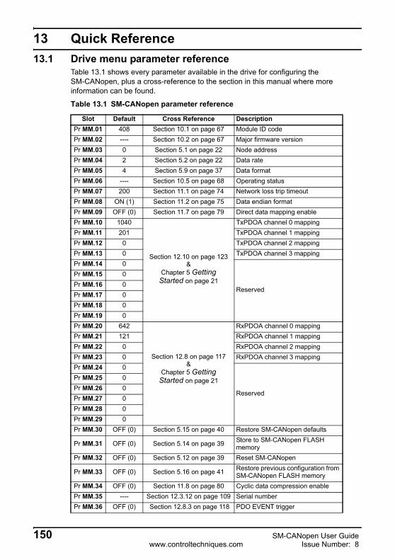
13 Quick Reference13.1 Drive menu parameter reference
Table 13.1 shows every parameter available in the drive for configuring theSM-CANopen, plus a cross-reference to the section in this manual where more information can be found.
Table 13.1 SM-CANopen parameter reference
Slot Default Cross Reference DescriptionPr MM.01 408 Section 10.1 on page 67 Module ID codePr MM.02 ---- Section 10.2 on page 67 Major firmware versionPr MM.03 0 Section 5.1 on page 22 Node addressPr MM.04 2 Section 5.2 on page 22 Data ratePr MM.05 4 Section 5.9 on page 37 Data formatPr MM.06 ---- Section 10.5 on page 68 Operating statusPr MM.07 200 Section 11.1 on page 74 Network loss trip timeoutPr MM.08 ON (1) Section 11.2 on page 75 Data endian formatPr MM.09 OFF (0) Section 11.7 on page 79 Direct data mapping enablePr MM.10 1040
Section 12.10 on page 123&
Chapter 5 Getting Started on page 21
TxPDOA channel 0 mappingPr MM.11 201 TxPDOA channel 1 mappingPr MM.12 0 TxPDOA channel 2 mappingPr MM.13 0 TxPDOA channel 3 mappingPr MM.14 0
Reserved
Pr MM.15 0Pr MM.16 0Pr MM.17 0Pr MM.18 0Pr MM.19 0Pr MM.20 642
Section 12.8 on page 117&
Chapter 5 Getting Started on page 21
RxPDOA channel 0 mappingPr MM.21 121 RxPDOA channel 1 mappingPr MM.22 0 RxPDOA channel 2 mappingPr MM.23 0 RxPDOA channel 3 mappingPr MM.24 0
Reserved
Pr MM.25 0Pr MM.26 0Pr MM.27 0Pr MM.28 0Pr MM.29 0Pr MM.30 OFF (0) Section 5.15 on page 40 Restore SM-CANopen defaults
Pr MM.31 OFF (0) Section 5.14 on page 39 Store to SM-CANopen FLASH memory
Pr MM.32 OFF (0) Section 5.12 on page 39 Reset SM-CANopen
Pr MM.33 OFF (0) Section 5.16 on page 41 Restore previous configuration from SM-CANopen FLASH memory
Pr MM.34 OFF (0) Section 11.8 on page 80 Cyclic data compression enablePr MM.35 ---- Section 12.3.12 on page 109 Serial numberPr MM.36 OFF (0) Section 12.8.3 on page 118 PDO EVENT trigger
150 SM-CANopen User Guidewww.controltechniques.com Issue Number: 8

Safety Inform
ationIntroduction
Mechanical
InstallationElectrical
InstallationG
etting Started
EDS Files
Cyclic D
ataN
on-Cyclic
Data
Control and
Status Words
Diagnostics
Advanced Features
CAN
open R
eferenceQ
uick R
eferenceG
lossary Of
Terms
Index
* Not supported by Commander SK or SX.
13.2 Virtual parameter referenceTable 13.2 shows every virtual parameter available in the SM-CANopen, plus a cross-reference to the section in this manual where more information can be found. Virtual parameters can only be accessed from the CANopen network using non-cyclic communications.
Pr MM.37 OFF (0) Section 12.15.1 on page 133 Enable DSP402 profilePr MM.38 OFF (0) ReservedPr MM.39 4
Section 11.10 on page 81TxPDO length
Pr MM.40 4 RxPDO lengthPr MM.41 0 Section 12.8.3 on page 118 TxPDO transmission typePr MM.42* 0 Section 11.13 on page 84 SM-Applications object priorityPr MM.43* 0 Section 11.14.3 on page 87 Synchronisation ModePr MM.44* 0 Section 11.14.4 on page 89 Synchronisation StatusPr MM.45* 0 Section 11.14.5 on page 89 Synchronisation PeriodPr MM.46* 0 Section 11.16.1 on page 95 Increments on PDO Transfer CyclePr MM.47 0
ReservedPr MM.48 0Pr MM.49 ---- Section 10.6 on page 69 SM-CANopen mapping statusPr MM.50 ---- Section 10.7 on page 72 SM-CANopen error codesPr MM.51 ---- Section 10.2 on page 67 Minor firmware version
Table 13.1 SM-CANopen parameter reference
Slot Default Cross Reference Description
Table 13.2 SM-CANopen virtual parameter reference
Slot 1 Default Cross reference DescriptionPr 61.01 ---- ---- Drive Pr MM.00 access
Pr 61.35 ---- Section 12.3.12 on page 109 Serial number
Pr 61.40 0
Section 11.9 on page 80
SM-Applications event task trigger (lowest slot)Pr 61.41 0 SM-Applications event task trigger (slot 1)Pr 61.42 0 SM-Applications event task trigger (slot 2)Pr 61.43 0 SM-Applications event task trigger (slot 3)
Pr 61.50 0 Section 8.2 on page 52
CT Single Word (Mode 1) non-cyclic data mapping parameter
SM-CANopen User Guide 151Issue Number: 8 www.controltechniques.com

13.3 Object referenceTable 13.3 shows all supported objects available within SM-CANopen. Plus a cross reference to the section in this manual containing more information on the object.
Table 13.3 SM-CANopen object reference
Index Name And Link Description Link
0x1000 Device Type Indicates the current configuration of the Unidrive SP and SM-CANopen
Section 12.3 on page 103
0x1001 Error Register Used by the SM-CANopen to indicate that an error has occurred. Section 12.3.1 on page 104
0x1002 Manufacturer Status Register
Mapped directly to the status word (Pr 10.40) in the Unidrive SP. Section 12.3.2 on page 104
0x1003 Pre-Defined Error
Returns 32-bit error code containing data from the last 4 emergency messages that were sent.
Section 12.3.3 on page 104
0x1005 COB-ID SYNCDefines the COB-ID that will be used for the synchronisation (SYNC) object.
Section 12.3.4 on page 105
0x1008 Manufacturer Device Name
Returns the string “SM-CANopen” to indicate the product name. Section 12.3.5 on page 106
0x1009Manufacturer
Hardware Version
Returns the string “UT77” to indicate the product hardware. Section 12.3.6 on page 106
0x100AManufacturer
Software Version
Returns a string to indicate the firmware version installed. Section 12.3.7 on page 106
0x1010 Store parameters
This object is used to save the communication parameters. Section 12.3.8 on page 106
0x1011 Restore default values
This object is used to restore default values. Section 12.3.9 on page 106
0x1014 COB-ID EMCY Defines the COB-ID to be used for the emergency object.
Section 12.3.10 on page 108
0x1017 Producer Heartbeat Time
The “heartbeat protocol” is a node protection system or error control service.
Section 12.3.11 on page 108
0x1018 Identity Object Returns general information about the SM-CANopen.
Section 12.3.12 on page 109
0x14000x15FF
RxPDOn communication
parameters
Communication information for RxPDOn Section 12.6 on page 113
0x16000x17FF
RxPDOn mapping
parametersMapping information for RxPDOn Section 12.7 on page 115
0x18000x19FF
TxPDOn communication
parameters
Communication information for TxPDOn Section 12.8 on page 117
0x1A000x1BFF
TxPDOn mapping
parametersMapping information for TxPDOn Section 12.9 on page 120
0x2800 RxPDO number configuration
This object is used for configuring the available RxPDOs. Section 12.5.1 on page 111
0x2801 TxPDO number configuration
This object is used for configuring the available TxPDOs. Section 12.5.2 on page 111
152 SM-CANopen User Guidewww.controltechniques.com Issue Number: 8

Safety Inform
ationIntroduction
Mechanical
InstallationElectrical
InstallationG
etting Started
EDS Files
Cyclic D
ataN
on-Cyclic
Data
Control and
Status Words
Diagnostics
Advanced Features
CAN
open R
eferenceQ
uick R
eferenceG
lossary Of
Terms
Index
14 Glossary Of Terms
Address: This is the unique network identification given to a networked device to allow communication on a network. When a device sends or receives data the address is used to determine the source and the destination of the message.
Bit: A binary digit, this may have the value of 1 or 0.
Block mapping: A method of mapping a range of consecutive parameters using only two ascending parameters. This means that by using two mapping parameters, up to 32 consecutive mappings may be made. See section 11.9 Unidrive SP: event task trigger in SM-Applications on page 80 for more information.
Byte: A collection of 8 binary digits that collectively store a value. This may be signed or unsigned.
CAN: The base network used for CANopen. The CANopen module does not support CAN commands.
CANopen: Builds on the basic CAN protocol by offering higher level functionality.
Casting: The process of changing between data sizes without changing the value represented, e.g. changing from 16 bit to 32 bit.
Compression: By default SM-CANopen transmits values as 32 bits on the network. It is possible by using compression to reduce the number of bits transmitted when sending 16 bit (or smaller) values on the network to 16 bit (32 bit values will still be transmitted as 32 bit values). This has the advantage of reducing the volume of traffic on the network and allowing more parameters to be mapped within SM-CANopen.
Consistency: Describes how data is transmitted between nodes on the network. If data is consistent it is transmitted from node to node as a single entity. Thus preventing data corruption where multiple bytes are transmitted or received individually.
Control word: A collection of binary digits that are used to control the drive. Features typically include directional controls, run controls and other similar functions.
CT Single Word non-cyclic: see mode 1 non-cyclic in this section.
Cyclic data: This consists of values that are sent at regular or cyclic intervals across the network. A typical use of cyclic data would be the transmission of a speed reference or a control word.
Data format: Determines the quantity and function of the data sent and received across the network.
Data rate: Determines the communication speed of the network, the higher the value the more data can be sent across the network in the same time period.
SM-CANopen User Guide 153Issue Number: 8 www.controltechniques.com

Device: A piece of equipment connected to a network, this may be any type of equipment including repeaters, hubs, masters or slaves.
Object Dictionary: A collection of the objects that are supported by the product.
Direct data mapping: Data is sent directly to the mapping parameters in the drive rather than the parameters redirecting the data to another parameter.
Double word: A 32 bit word, this may be signed or unsigned.
Earthing: Describes the electrical safety or screening connections for the module.
Endian format: When a value uses more than 8 bits to represent it’s value it needs to be sent in sets of 8 bits (bytes) across the network, the endian format determines the order the bytes that constitute the whole value are transmitted.
Event task: A special way to use a message or change of state to trigger a software routine.
Long word: A 32bit data word that may be signed or unsigned.
Mapping: The process of linking CANopen values to parameters within the drive.
Master: The controlling device on the network, generally this will include programming features.
Mode 1 non-cyclic: A method of sending non-cyclic data using a single word.
Network loss trip: A method to determine when a node has lost communication with the master.
Node: A device on the network. This may be either a device such as a drive or part of the network such as a repeater.
Non-cyclic data: Data that is requested or sent by the master as required. This is not sent on a regular basis and generally allows access to any parameter. This is useful for occasional changes or configuration purposes.
PDO: Process Data Object. This is the method that CANopen uses to transmit and receive cyclic data.
Poll rate: The rate at which cyclic data is sent and received on the network.
PPO 4 Word non-cyclic mode: see Mode 2 non-cyclic in this section. This is not the same as PPO4 mode.
Response ID: The response code of the message received when using PPO4 word non-cyclic communication.
Scan rate: See Poll rate in this section.
154 SM-CANopen User Guidewww.controltechniques.com Issue Number: 8

Safety Inform
ationIntroduction
Mechanical
InstallationElectrical
InstallationG
etting Started
EDS Files
Cyclic D
ataN
on-Cyclic
Data
Control and
Status Words
Diagnostics
Advanced Features
CAN
open R
eferenceQ
uick R
eferenceG
lossary Of
Terms
Index
Screening: A connection to provide additional immunity to noise used on a network cable.
SDO: Service Data Object. These provide non-cyclic access to the CANopen object dictionary in each slave.
Segment: An electrically separate part of the network. Each segment requires correct termination to ensure reliable operation. Due to electrical limitations the maximum number of devices on a segment is limited to 32.
Slave: A device on the CANopen network such as a drive or sensor. A slave device will only respond to messages from a master.
Status word: A value that denotes the status of the drive. Each bit within the word will have a specific meaning.
Stuff Bits: Stuff bits are used by CANopen to ensure that each CANopen device does not transmit a long stream of consecutive 1s or 0s.
Telegram: A message used within mode 1 non-cyclic data communication. This term is sometimes used to represent a generic message on the network.
Termination: This is used at both ends of a network segment to prevent reflections and reduce noise.
Watchdog: A method used to determine if a communication system is healthy. A typical watchdog scheme uses a handshaking system to check both the master and slave are participating in communications.
Word: A collection of 16 binary digits.
SM-CANopen User Guide 155Issue Number: 8 www.controltechniques.com

Index
Numerics16-bit parameter access .............................................................................53
AAbove set speed .........................................................................................65Activate bit timing .....................................................................................128ASSOCIATEINTOPCOMMS ......................................................................83At speed .....................................................................................................65Avoiding block mapping .............................................................................79
BBack-up - parameters to SM-CANopen FLASH memory ...........................40Back-up power supply ................................................................................19Basic data types .......................................................................................102Below set speed .........................................................................................65Blank mapping parameters ........................................................................49Block ...........................................................................................................78Block mapping ............................................................................................77Byte order ...................................................................................................75
CCable length ...............................................................................................20Cautions .......................................................................................................6Changing data rate ...................................................................................127Changing PDO mapping parameters .........................................................48COB-ID EMCY .........................................................................................108COB-ID SYNC ..........................................................................................105Communication profile objects .........................................................102, 152Complete parameter reference ................................................................150Compliance with regulations ........................................................................7Configuration error .....................................................................................69Configure bit timing ..................................................................................127Configure node-ID ....................................................................................127Conformance certificate .............................................................................11Connections - cable shield .........................................................................19Control and status words ............................................................................62Control word bit functions ...........................................................................63Conversion factors ...................................................................................133Current limit ................................................................................................65Cyclic data ..................................................................................................45Cyclic data compression ......................................................................46, 80
DData size ....................................................................................................46Default COB-IDs and transmission type .....................................................37Default parameters - restore ....................................................................107Device profiles ..........................................................................................133Diagnostics .................................................................................................66DINT ...........................................................................................................95Direct data mapping ...................................................................................79
156 SM-CANopen User Guidewww.controltechniques.com Issue Number: 8

Safety Inform
ationIntroduction
Mechanical
InstallationElectrical
InstallationG
etting Started
EDS Files
Cyclic D
ataN
on-Cyclic
Data
Control and
Status Words
Diagnostics
Advanced Features
CAN
open R
eferenceQ
uick R
eferenceG
lossary Of
Terms
Index
DPL function call ........................................................................................82Drive active .................................................................................................65Drive healthy ..............................................................................................65Dual SM-Applications fitted ........................................................................77Dynamic brake active .................................................................................65Dynamic brake alarm .................................................................................65
EEDS files .....................................................................................................43Electrical safety ............................................................................................6Emergency error codes ............................................................................131Emergency object .....................................................................................130Emergency object state ............................................................................131Emergency object state transitions ..........................................................132Enable DSP402 device profiles ................................................................133Endian format .............................................................................................75Environmental limits .....................................................................................7Equipment malfunction .................................................................................6Error code ...................................................................................................72Error register ....................................................................................104, 132Event task reason codes ............................................................................81Event task trigger in SM-Applications .........................................................80Example function call .................................................................................84
FFlexible PDO numbering ..........................................................................109
GGeneral information ......................................................................................2Generating emergency objects from DPL ................................................132Getting started ............................................................................................21Glossary of terms .....................................................................................153
HHardware enable ........................................................................................62
IIdentity object ...........................................................................................109Internal interrupts .......................................................................................96Inter-option communication timing .............................................................75
LLayer setting services (LSS) ....................................................................125Linking object dictionary entries to DPL program variables .......................82Local solutions module parameter access .................................................76
MMaintaining DPL variables ..........................................................................84Manufacturer device name .......................................................................106Manufacturer hardware version ................................................................106Manufacturer software version .................................................................106Manufacturer status register .....................................................................104Mapping parameter values .......................................................................122Mapping status ...........................................................................................69Mapping To SM-Applications parameters ..................................................76
SM-CANopen User Guide 157Issue Number: 8 www.controltechniques.com

Mode 1 - CT single word mode ..................................................................52Motor ............................................................................................................7
NNetwork length ...........................................................................................20Network load ............................................................................................100Network loss trip .........................................................................................74Network management objects (NMT) .......................................................123NMT commands .......................................................................................124Node address .............................................................................................22Non-cyclic data ...........................................................................................50Notes ............................................................................................................6
OObject association rules .............................................................................83Operating states .......................................................................................108Operating status ...................................................................................38, 68Optimisation ...............................................................................................84Output channel ...........................................................................................98
PParameter data object mapping ...............................................................133Parameters - adjusting .................................................................................7Parameters - complete reference .............................................................150PDO counter ...............................................................................................82PDO data mapping errors ..........................................................................48PDO1 2 channels (default) .........................................................................47PDO1 with 1 channel and CT single word non-cyclic data .........................48PDOA length ..............................................................................................81Position control with interpolation ...............................................................93Position control without interpolation ..........................................................90Pre-defined error field ...............................................................................104Process data object (PDO) .........................................................................45Producer heartbeat time ...........................................................................108Profile torque mode ..................................................................................143Profiles .......................................................................................................48
QQuick reference ........................................................................................150
RRegenerating ..............................................................................................65RMINT, RMINT_1MS and RMINT_POS ....................................................96Running at or below minimum speed .........................................................65RxPDO COB-ID ........................................................................................113RxPDO communication parameters .........................................................113RxPDO event timer ..................................................................................115RxPDO inhibit time ...................................................................................115RxPDO mapping parameters ...................................................................115RxPDO transmission type ........................................................................114
SSafety of personnel ......................................................................................6SDO abort codes ........................................................................................51Secure disable ..............................................................................................6
158 SM-CANopen User Guidewww.controltechniques.com Issue Number: 8

Safety Inform
ationIntroduction
Mechanical
InstallationElectrical
InstallationG
etting Started
EDS Files
Cyclic D
ataN
on-Cyclic
Data
Control and
Status Words
Diagnostics
Advanced Features
CAN
open R
eferenceQ
uick R
eferenceG
lossary Of
Terms
Index
Select product code ..................................................................................126Select revision number .............................................................................126Select serial number .................................................................................126Select vendor ID .......................................................................................126Service data object (SDO) ..........................................................................50Set-up flow chart ........................................................................................26Set-up using non-cyclic data ......................................................................61Slave RMINT accuracy .............................................................................100SM-CANopen timing ...................................................................................91SM-LON module - front view ......................................................................13Spurs ..........................................................................................................20Status word ................................................................................................64Status word bit functions ............................................................................65Switch mode global ..................................................................................125Switch mode selective ..............................................................................126SYNC absolute timing accuracy .................................................................99SYNC jitter ................................................................................................100Synchronisation period ...............................................................................89Synchronisation status ...............................................................................89Synchronising Unidrive SP via the CANopen network ...............................90
Ttarget_torque ............................................................................................143Timing and data transfer consistency .........................................................95torque_actual_value .................................................................................143torque_profile_type ...................................................................................144torque_slope .............................................................................................144TxPDO COB-ID ........................................................................................118TxPDO communication parameters .........................................................117TxPDO inhibit time ...................................................................................119TxPDO mapping parameters ....................................................................120TxPDO number configuration ...................................................................111TxPDO transmission type .........................................................................118
UUnused PDO data channels .......................................................................48
VVelocity mode objects ..............................................................................145Virtual parameter reference ......................................................................151vl_control_effort ........................................................................................146vl_velocity_acceleration ...........................................................................148vl_velocity_deceleration ...........................................................................148vl_velocity_demand ..................................................................................146vl_velocity_min_max_amount ..................................................................147
WWarnings ......................................................................................................6
ZZero speed .................................................................................................65
SM-CANopen User Guide 159Issue Number: 8 www.controltechniques.com

0471-0020-08