Embed Size (px)
DESCRIPTION
Manual operación sdd2000
Citation preview

SAMPLINGDIGITALDELAY
OWNER'S MANUAL
KORG

The SDD-2000 is a new kind of digital delay that is designed to work
IUsed as a conven
tional delay ma
chine, the SDD-2000
can provide very long delay
times of up to. 4368ms. Up to
64 effects such as chorus,
flanging, doubling, and echo
can be programmed for rapid
access. MIDI program change
data can be used to select
stored effects.
N In the trigger over-
I dub mode, a footL switch, drum ma
chine trigger signal, MIDI tim
ing clock, or other signal can
be used to set the delay time,
making it easy to match the
tempo of the music.
The sequencer and
sampling modes al-
low audio inputs of
up to 4368ms to be recorded
and then reproduced when
desired. Coupled with a MIDI
keyboard (or other MIDI con
trol device) the sampled
sound can be "played" (like
on a sampling keyboard in
strument).

n
Congratulations and thank you for
purchasing the Korg SDD-2000.
For optimum performance,
long term reliability and safety,
please read this manual before use.
with MIDI data, thereby offering new and exciting capabilities.
4Rec cancel, program
up, and other prac
tical functions add to
the value of this tjnit for live
performance.
Three outputs —
DIRECT, +MIX,
- MIX — offer varie
ty of stereo reproductiion pos
sibilities.
6Incremental control
of all parameters
and a 6-column dis
play add to operational conve
nience.
(■KCAll
MTV TMEX4 PWOG/HUU
: — ■■■ PROG NO. *
eHV twe wwte ' '
•^ • ;• -..
[ _ - ' PROGRAMMER
—■
OATA/TME(mt)
•ssss*
DIGITAL DELAY
POWER

To avoid malfunction do not use this unit in the following locations for long periods of time:• In direct sunlight ^^^^ « S
• Exposedtoextrernesoftemperature or humidity;• In sandy or dusty places.
POWER SUPPLY■• Useonly with ratedAC voltage. If you will be using
this unit ina country having a different voltage, besure to obtain the proper transformer to convert to
• To helpiprevent rioiseand diBgraded sound quality,avoid usingthe sam&outletas other equipment orbranching off extension cords shared by otherequipment
HANDLE GENTLYKnobs and switches are designed to provide positiveoperation with a light touch. Excessive force maycause damage:
MAINTENANCEWipethe exterior with a soft, dry cloth. Never use paintthinner, benzene or other solvents.
■ ■.■•■■•' ■ I • ■ ■" ■ .■■'*"
PREVENTING ELECTRICALINTERFERENCEErratic performance may be caused by electrical in-terference from nearby appliances (radio, TA/, etc:)rOTespecially those with motors. Avoid operating this unitnear possible sources of interference.
KEEP THIS MANUALStore this manual in a safe place of future reference.
MM
Id ipireyi^
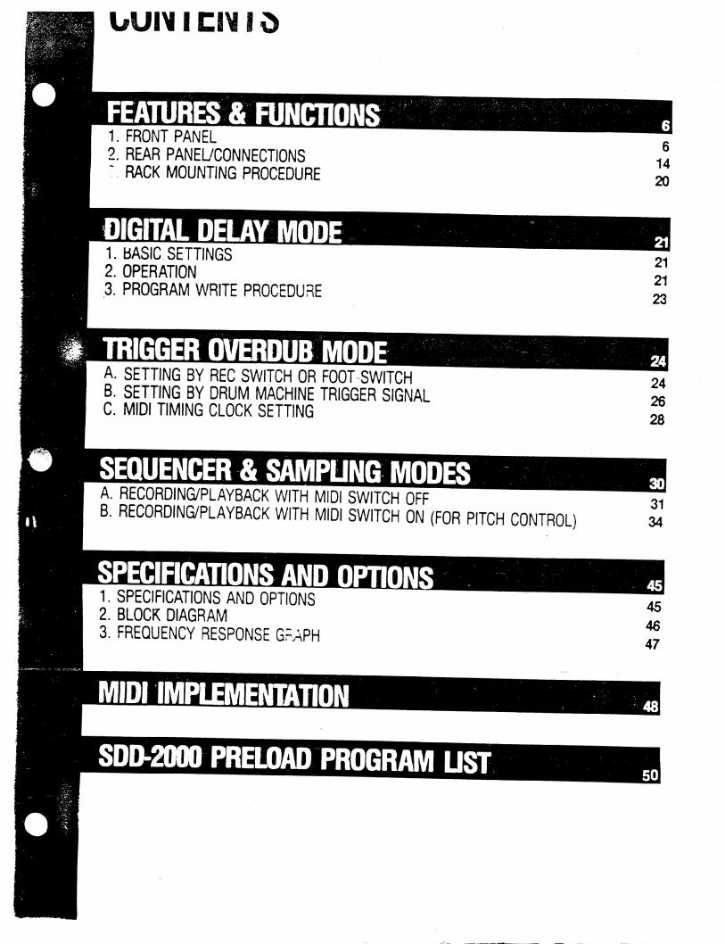
FEATURES & FUNCTIONS1. FRONT PANEL
2. REAR PANEL/CONNECTIONS:. RACK MOUNTING PROCEDURE
DIGITAL DELAY MODE1. BASIC SETTINGS2. OPERATION
3. PROGRAM WRITE PROCEDURE
6
14
20
21
21
23
A. SETTING BY REC SWITCH OR FOOT SWITCHB. SETTING BY DRUM MACHINE TRIGGER SIGNALC. MIDI TIMING CLOCK SETTING
24
26
28
A. RECORDING/PLAYBACK WITH MIDI SWITCH OFFB. RECORDING/PLAYBACK WITH MIDI SWITCH ON (FOR PITCH CONTROL)
1. SPECIFICATIONS AND OPTIONS2. BLOCK DIAGRAM
3. FREQUENCY RESPONSE GRAPH
45
46
47
SDD-2000 PRELOAD PROGRAM UST

1 FRONT PANEL
INPUT SECTION OUTPUT SECTION
2 Input LEVEL Control—
1 HEADROOM Indicator-
o
HEAOFDOM
♦ 6dB
008
-KWB
2+ \U
0 10
INPUT
OWECT
4 j
i.*9
-3 DIRECT Volume Control-4 BYPASS Switch
-5 REC CANCEL LED
/
|RPCCLNC£L|
C)
REC TWG
10
BYPASSME
OUTPUT
•RKOVSOue SEO SAMPUNG
recSync
REC SYNC SECTION
6 REC Switch
7 TRIG OVERDUB Switch-
8 SEQ Switch
9 SAMPLING Switch-
10 TRIG LED
Mia Ef
f

PROGRAMMER SECTION
-ism -
if
PROG NO )ATA/flME(ms) \
PROGRAMMER
-12 FREQ Switch-14 EFFECT Switch
-13 INTENSITY Switch
-15 FEEDBACK Switch
-16TIMEX 4 Switch-17 TIME Switch
-18 PROG/PARA (REC CAL)
-19 WRITE Switch
-20 DISPLAY
-21 INCREMENTAL CONTROL
INCREA ENTAL
CONTROL KORC *» t00°SAMPLIMG
DIGITAL DCLAV
POWER
Switch -22POWER Switch

INPUT SECTION.I HEADROOM Indicator
This LED meter sihows input signal level. However,nothing is indicated during the 9-second mutingperiod after power is turned on or during bypassoperation.
2 Input LEVEL ControlUsed to adjust input signal level.
OUTPUT SECTION.3 DIRECT Volume Control
is controls the volume of the direct sound in the
+ MIX and - MIX outputs on the rear panel.
4 BYPASS Switch
J this switch is on, only the direct sound is sentto the outputs. During bypass operation the DIRECTvolume control setting has no effect; the input signalis sent to the output jacks without any change.Bypass operation is indicated by an LED. Press thisswitch again to return to the previous effect.This switch cannot be used during recording in thesequencer and sampling modes.
REC CANCEL5 REC CANCEL LED
This LED illuminates during REC CANCEL operation.For details, see the explanation for the rear panelREC CANCEL jack.
O*ECT |REC CANCEL |
« ? •O
BYPASS
OUTPUT■a

REC SYNC SECTION
mo saotlmq
SEERECSYNC
6 REC Switch
In the sampling and sequencer modes this is used
as the recording switch. In the trigger overdub mode
it is used to manually set the delay time.
7 TRIG OVERDUB Switch
This switch is used to select the trigger overdubmode with automatic setting of delay time.
t SEQ Switch
This selects the sequencer mode for recording and
repeated playback of phrases of up to 4368ms.
SAMPLING Switch
This selects the sampling mode which allows recording of audio signal inputs and reproduction of
the sampled signal when triggered by a foot switchor other signal source.
10 TRIG LED
This illuminates when a trigger signal is input to the
rear panel trigger jack during trigger overdub, sampl
ing mode operation.
csync
MIDI11 MIDI Switch
When this switch is on, its LED lights up and theSDD-2000 can receive MIDI data.

PROGRAMMER SECTION.12 FREQ Switch
This selects display of the modulation frequency
(speed) value and allows adjustment using the incre
mental control knob.
Displayed Value
n
u
Z* iJf t
Modulation Speed
Slow
♦
Fast
13 INTENSITY Switch
This selects display of the modulation intensity
(depth) value and allows adjustment using the incre
mental control knob.
Displayed Value
nu
I
Z* iji i
Modulation Depth
Shallow
t
Deep
BTKX4
I O I
* About Modulation
Effects such as chorus, vibrato, and flanging are
produced by using the internal LFO (low fre
quency oscillator) to vary (modulate) the delay
time.
14EFECT Switch
This selects display of the volume level of the
delayed signal (or the sampled signal to be reproduc
ed) and allows adjustment using the incremental
control knob.
Displayed Value
nu
Effect Signal Volume
No effect sound
Maximum

15 FEEDBACK SwitchSelects display of the amount of feedback and its
phase. This also allows adjustment of the feedback
value using the incremental control knob.
Displayed Value
.I' i
A
— -9
nu
I
Z* t
Feed Back Level
Maximum inverted
(cause oscillation)
I
No feedback
Maximum positive
(causes oscillation)
About Feedback
Feedback or "regeneration" is a matter of taking
part of the signal coming out of the delay line and
feeding it back into the input to be processed
again. The amount of feedback and its phase help
establish the effect produced. With long delay
times, feedback level simply determines the
number of repeats or echoes. In flanging and
other short delay effects, the feedback level and
phase affect the tone color of the sound.
Runaway oscillation will occur if the feedback
level is set too high.
16 TIME x 4 Switch
This selects the "x4" mode which allows delay (or
recording/sampling) times of up to 4368ms. When
this is off, the maximum delay time is 1092ms.
An LED lights up to indicate 4 mode.
The x1 mode (the normal mode when x4 is not
selected) has superior high frequency response.
17TIME Switch
This is used to enable setting of the delay (or record
ing/sampling) time. In the x1 mode, the display
shows times of from 0. 0 to 1092ms; in the x 4 mode
it shows from 0 to 4368ms.
At settings of up to 10ms in the x 1 mode the display
gives fractional indications to the first decimal place.

18 PROG/PARA (RECCAL)
In the delay mode, this switches between allowing
"program change" and allowing editing of individual
parameters. In the sequencer and sampling modes it
allows "recording calibration." (For details, see the
section on the REC CAL function.)
19 WRITE Switch
This is used to store programs in memory. For
details see the section on "Writing a Program."OTY-nMEx4 mum*
0 0 0I PWQGNQ.
3; oiIs*
MER
20 DISPLAY
Shows the program number and the values of par-ticular parameters.
RAMMER
21 INCREMENTAL CONTROL -
This is used to adjust, set or select parameters, pro-gram numbers, MIDI channels, and so on.
When used to set the delay time, this controller issensitive to how fast you turn the knob. It is designedto change one step at a time when turned slowly,
and change in larger amounts when turned rapidly.

POWER{MENTAL
•rraoc KOMi ■M000SAMPLINGMOfTAL DCLAy
POWER
22 POWER SwitchThis unit takes about nine seconds to initialize itself
after the power is turned on. All functions are in
operative during this muting time.

I REAR PANEL/CONNECTIONS
CONTROL SECTION
6 BYPASS jack
7 REC CANCEL jack-
8 PROGRAM UP jack-
9 REC jack
10 TRIGGER jack—
11 TUNE Control—12 MIDI IN jack
13 MIDI THRU jack-
wmmmm
To other MIDI
equipment
From MIDI keyboard,
sequencer,
drum machine,
or computer.
From Drum Mi in<
(DDM-1107220,KPR-77, etc.) or footswitch (PS-1 etc.)

INPUT/OUTPUT SECTION
<£>TRIG R«C PRXjUP CANCEL BYf>ASS
"-GNO 1-bNO "UGNO UGNO
-3 DIRECT Output
-4 + MIX Output
-5 - MIX Output
-2 ATTENUATOR1 INPUT jack
hum foot switch
To amplifier(s)
or mixing console
(MM-25, KMX-8, etc)
From electric guitar,
bass, microphone,
keyboard, mixing. .-
, etc..-..:,-:
15

INPUT/OUTPUT SECTION .This section has jacks for the audio input signal and output signals.
1 INPUT Jack
For signal from electric guitar, bass, microphone,
keyboard, etc.I I
(GAM:1MTY)
2 ATTENUATOR
Set this switch to the position suitable for the type of
input signal used.
-WPl/T-
(GMNjJMTV)
• Input Level Adjustment
• If the input level is too high it will cause distor
tion. If it is too low, it will reduce the signal-to-
noise ratio. Adjust input level so that the HEAD
ROOM indicator + 6dB LED lights occasionally
on maximum signal peaks.
• Remember to check and readjust input level
after changing feedback level. This is necessary
because the amount of feedback will change the
signal level within the circuitry.
• Set the ATTENUATOR to the correct position for
the signal source before adjusting input level.
Switch
-10dB
-35dB
Input Signal Source
From synthesizer, drum machine, other
electronic instrument, mixing console,
or audio system
From electric guitar, bass, electric
piano, microphone, or other low level
signal source.
3 DIRECT Output ir_^_This provides the direct sound (the input sound) only. -OUTPUT
BYPASS DIRECT
+ MIX Output
This provides a mixed output.of the direct and effect
(or recorded/sampled) sounds. Balance is determin
ed by the front panel DIRECT volume control setting
and the PROGRAMMER section EFFECT setting.
OUTPUT
* MIX - Mix
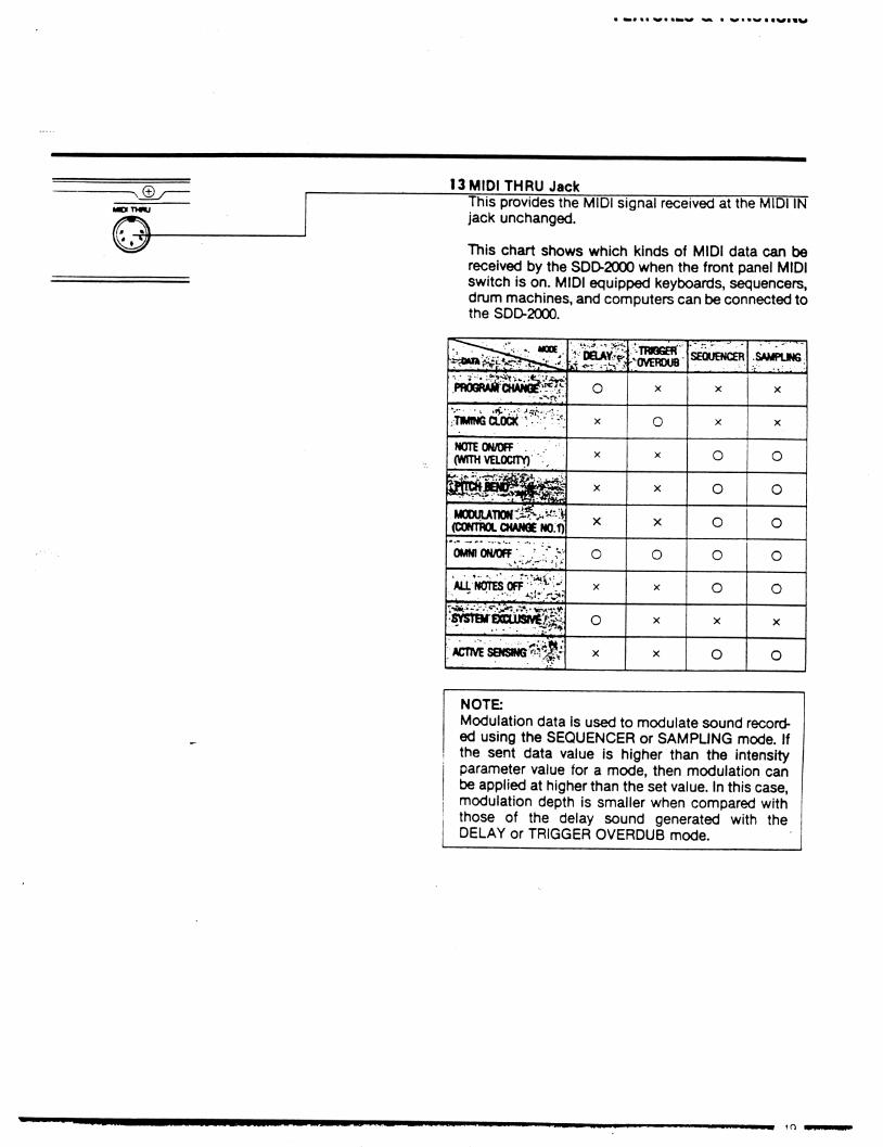
13 MIDI THRU Jack
This provides the MIDI signal received at the MIDI IN
jack unchanged.
This chart shows which kinds of MIDI data can bereceived by the SDD-2000 when the front panel MIDI
switch is on. MIDI equipped keyboards, sequencers,
drum machines, and computers can be connected tothe SDD-2000.
pwgra^chamS:^
TiitNGaocK : •; -'t
NOTE ON/OFF .
(WITH VELOCITY) \
M0OUI>Tm^.^:i(CONTROL CHANGE NO.f)
omniowoff .. ;';-
Aa'fWTESOFF"^^
svsTDr£xcuiav6^H
ACTIVE SOSWG?^
■:i ooa^v
o
X
X
X
X
O
X
O
X
. ■'• TnraGEn
"OVERDUB
x
O
X
X
X
O
X
X
X
SEQUENCER
X
X
O
O
o
o
o
X
o
•5AwHTJN6 ;
X
X
o
o
O
O
O
X
o
NOTE
Modulation data is used to modulate sound record
ed using the SEQUENCER or SAMPLING mode. Ifthe sent data value is higher than the intensity
parameter value for a mode, then modulation can
be applied at higher than the set value. In this case,modulation depth is smaller when compared with
those of the delay sound generated with theDELAY or TRIGGER OVERDUB mode.

rcai unco oc rununuiio
RACK MOUNTING PROCEDURE
PROCACKEDUR
VIOUNTING
A
o
o
o
Attach using supplied screws.
If there is a gap of around 3mm or more here, fill the
rear area with something to keep the unit from sagging.

—OUTPUT
♦ mix -mix -a** -«
(GAM:UNmO
5 -MIX Output
This provides an out of phase mix of the direct and
effect sounds. Balance is determined in the same
way as for the + MIX output.
About Input/Output Level
Input and output level are at unity (one to one) in
the SDD-2000. Output level is the same as input
level.
Using the Outputs
The three output jacks can be connected
several ways to create stereo-like effects.
in
Example: 1.
Connect the DIRECT and + MIX outputs to sepa
rate amplifiers or separate mixing console chan
nels and pan them to opposite sides. Set the front
panel DIRECT volume control to "0" (so that only
the effect sound appears in the + MIX output). With
short delay times this gives a rich stereolike sound.
With long delay times the sound appears to shift
from one side to the other.
Example: 2
Use + MIX and - MIX connected to separate ampli
fiers or separate mixing console channels and pan
them to opposite sides. The out-of-phase effect
component of the - MIX output creates a very
spacious sound. Especially good for chorus, flang
ing, and similar effects.
CONTROL SECTIONThe jacks in this section are used with foot switches, drum nnachines,
MIDI signals, and so on for control of various SDD-2000 functions.
6 BYPASS Jack
For foot switch control of the BYPASS function. Us
ed the same way as the front panel BYPASS switch.

FEATURES & FUNCTIONS
7 REC CANCEL Jack
When a foot switch that is connected to this jack is
depressed, the SDD-2000 switches to the RECCANCEL mode. This leaves the effect sound that is
present at the instant the foot switch is depressed
and switches the input signal to bypass the delay cir
cuitry. While REC CANCEL is on, the front panel
REC CANCEL LED illuminates.
8 PROGRAM UP Jack
The selected program number is advanced each
time a foot switch connected to this jack is depress
ed (in the delay mode).
PWOGUP CANCEL
~t-OMD ~
RECf»«OGUP CANCEL
"Lgmd
9 REC Jack
For foot switch operation with the same function as
the front panel REC switch, (Used for modes other
than the delay mode.)
10 TRIGGER Jack .
—For a trigger signal input from a drum machine or
foot switch.This triggers playback of sampled sounds (in thesampling mode) or sets the delay time (in the trigger
overdub mode).The front panel TRIG LED illuminates every time a
trigger signal is received.
Foot Switches to be Used with Control JacksFoot switches to be used with these controljacks should be the type that is on during the
period the foot switch is depressed. Such footswitches include the Korg PS-1 and S-2.
. cormot
two
©
11 TUNE Control .
This lets you adjust the pitch of the reproduced
sound by up to ±50 cents in the sampling and se
quencer modes.
12 MIDI IN Jack
This jack is for reception of MIDI data from a MIDI
keyboard, sequencer, drum machine, or computer.
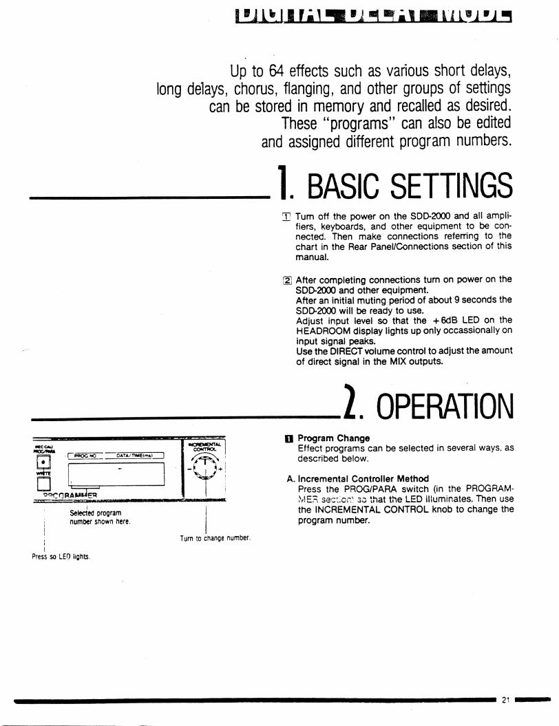
Up to 64 effects such as various short delays,
long delays, chorus, flanging, and other groups of settings
can be stored in memory and recalled as desired.
These "programs" can also be edited
and assigned different program numbers.
1. BASIC SETTINGS
ffCCCAO
n
nUJ
P«OG NO 0ATA/T1ME<m»| ]
t
9OCMEKTAL
CONTROL
,.. LjSelected program
number shown here.
Turn to change number.
T Turn off the power on the SDO2000 and all ampli
fiers, keyboards, and other equipment to be con
nected. Then make connections referring to the
chart in the Rear Panel/Connections section of this
manual.
\2\ After completing connections turn on power on the
SDD-2000 and other equipment.
After an initial muting period of about 9 seconds the
SDD-2000 will be ready to use.
Adjust input level so that the +6dB LED on the
HEADROOM display lights up only occassionally on
input signal peaks.
Use the DIRECT volume control to adjust the amount
of direct signal in the MIX outputs.
I OPERATIONQ Program Change
Effect programs can be selected in several ways, as
described below.
A. Incremental Controller Method
Press the PROG/PARA switch (in the PROGRAM
MER section*- 30 that the LED illuminates. Then use
the INCREMENTAL CONTROL knob to change the
program number.
Press so LED lights.
DIGITAL DELAY MODE
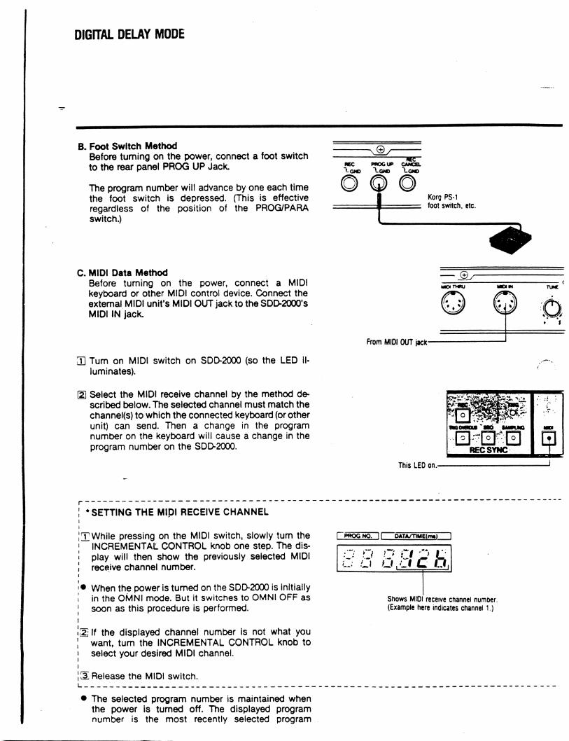
B. Foot Switch Method
Before turning on the power, connect a foot switch
to the rear panel PROG UP Jack.
The program number will advance by one each time
the foot switch is depressed. (This is effective
regardless of the position of the PROG/PARA
switch.)
NEC PHOGUP CANCEL
Korg PS-1
foot switch, etc.
C. MIDI Data Method
Before turning on the power, connect a MIDI
keyboard or other MIDI control device. Connect the
extemal MIDI unit's MIDI OUT jack to the SDD-2000's
MIDI IN jack.
3] Turn on MIDI switch on SDD-2000 (so the LED il
luminates).
g] Select the MIDI receive channel by the method de
scribed below. The selected channel must match the
channel(s) to which the connected keyboard (or other
unit) can send. Then a change in the program
number on the keyboard will cause a change in the
program number on the SDD-2000.
From MIOI OUT jack
MO THRU MO IN TUNE
■6» %
This LED on.-
• SETTING THE MIDI RECEIVE CHANNEL
T While pressing on the MIDI switch, slowly turn the
INCREMENTAL CONTROL knob one step. The dis
play will then show the previously selected MIDI
receive channel number.
• When the power is turned on the SDD-2000 is initially
in the OMNI mode. But it switches to OMNI OFF as
soon as this procedure is performed.
[2] If the displayed channel number is not what you
want, turn the INCREMENTAL CONTROL knob to
select your desired MIDI channel.
S Release the MIDI switch.
pPWOGNO. DAWTlM£(m«)
O O O O Q LU U U.Ll C LI,
Shows MIDI receive channel numoer.
(Example here indicates channel 1.)
• The selected program number is maintained when
the power is turned off. The displayed program
number is the most recently selected program

PffOGNO 1| 0ATA/T1M€(m«)
PROGRAMMER-This cct lights up
B Editing
Program contents can be edited by the followingmethod.
QD Press the PROG/PARA switch so that the LED goes
out »r
(2 Press the switch for the parameter that you want to
change.
• When you press one of the parameter switches (such
as FREQ, INTENSITY, EFFECT, FEEDBACK, TIME)
its LED will illuminate and the value of that
parameter will be shown on the display.
Use the INCREMENTAL CONTROL knob to adjust
the value of the selected parameter.
• The time mode switches back and forth between x 4
and x 1 each time the TIME x 4 switch Is pressed.
• A dot at the left side of the data display lights up
when a value has been changed. The dot goes out if
you return to the previously stored value.
NOTE:
•The edit will be cancelled if you change to a different
program number and then return to the edited pro
gram number. j
• Programs remain as edited if the power is turned off
and then turned on again.
}. PROGRAM WRITE PROCEDUREOTCCAU
*OG/MM
PILJ ;...
^ROGR
**K)GNO 11 OATA/TlMEtms) ! -
Flashing
Press WRITE switch.
Jj Select a program that is similar to the effect that you
want to create.
2 Edit to obtain the desired effect.
3 Press the WRITE switch. The displayed programnumber will flash on and off.
A Select the program number under which you wish to
save your effect. The program number can be
selected by the INCREMENTAL CONTROL knob, by
a PROG UP foot switch, or by MIDI program changedata.
Si Press the WRITE switch again to complete the program write procedure.

TRIGGER OVERDUB MODE
This mode uses a foot switch or drum machine trigger signal (or front panelREC switch) or a MIDI timing clock signal to set the delay time.This makes it easy to match delay time and song tempo.
A SETTING BY REC SWITCHOR FOOT SWITCH
1. BASIC SETTINGQ] Turn off SDD-2000 and all equipment to be con
nected. Make connections referring to the RearPanel/Connections section of this manual.
NOTE:In this case, do not plug anything into the TRIGjack. If anything is plugged into the TRIG jack then
the front panel REC switch can not be used to setthe delay time. (The TRIG jack is used when a drummachine is used to determine the delay time, as
described later.)
gj Turn on power after completing connections. TheSDD-2000 is now in the delay mode. Adjust input
level.
1. DELAY TIME SETTINGi Press the TRIG OVERDUB switch so that its LED is
on. This changes the SDD-2000 from the delay mode
tothe trigger overdub mode.
At this point, parameter values set m the delay modeare carried over unchanged into the trigger overdub
mode.
Flashing -
This LED on
me
O
TWGCWBPUi SEO
REC SYNC
]2 The Display appears as shown here.
The time mode switches back and forth between x 1
and x 4 each time the TIME x 4 switch is pressed.
The x4 mode enables delay time of up to 4368ms.
Maximum delay time in the x 1 mode is 1092ms.
FWEQ tfTEHSmr -nMEx4
[o] [TlJTl ITEFFECT FEEDBACk THE WfTTE
r pwogwo. QATAyTIM£|m»)
□-H,
PROGRAMMER
Indicates thai aeiay time
Indicates time mode can now be set
(x4 mode shown here)

wee
mmcofctdt U6 iAUa
REC SYNC
-Press REC switch
(or foot switch)
[1 Press the REC switch (or foot switch) to begin
measurement of the delay time.
PROG NO.
_ UI
DATA/T1ME(ms)
This counts up as
the delay time is measured.
.4. Now press the REC switch (or foot switch) a second
time. Your delay time is now the time measured be
tween the two times that you pressed the switch.
However, if the elapsed time reaches the maximum,
then the display stops there. The maximum is
1092ms \r the x1 mode and 4368ms in the x4
mode.
This method of setting the delay time makes it easy
to match the tempo of the music.
You can now continue performing using the delay
time just set.
3. OPERATION AFTER.SETTING DELAY TIME
SHEEFFECT FEEDBACK TKg WWTE
f PWOGNO. If 0ATA/TTM£(m») 1
EFFECT FEEDBACK Tit W
b b m □I IJJ I:
PROGRAMMER
Shows delay time setting.
Parameter values can be
chance while pressing these
Sw .
! OATA/TIME(m«
ISB 1•
MdCMCNTAL
CONTROL
-* ji-t-4 Turn to adjust parameter value
(while keeping parameter
switch depressed)
• Editing Parameters
After setting the delay time, you can edit the various
parameters whose switch LEDs are flashing (REC,
INTENSITY. EFFECT, FEEDBACK). To edit a para
meter, depress its switch and at the same time turn
the INCREMENTAL CONTROL knob.
• To return to the time mode
Press the TIME x4 switch to return to the time
mode. This takes you back to step 2.
• To reset the delay time
Press the REC switch. This begins measurement of
time, as in step 3.
• To return to delay mode from trigger overdub mode.
Press the TRIG OVERDUB switch so that is LED
goes out.
This returns you to the delay mode. The delay time
and time mode (x 1 or x4) values set in the trigger
overdub mode are retained.
Other parameter values are those of the delay mode.

TRIGGER OVERDUB MODE
B SETTING BY DRUM MACHINETRIGGER SIGNAL
1. BASIC SETTINGCD Turn off power on SDD-2000 and equipment to be =
connected.
g] Connect drum machine's trigger out jack to SDD-
2000fs TRIG input jack. Refer to Rear Panel/Connec
tions section of this manual for details about other
connections.
ID Tum on power after completing all connections. The
SDD-2000 is now in the delay mode. Adjust input
level.
2. SETTING THE DELAY TIME.
P«OGUP
OD Change to the trigger overdub mode by pressing the
TRIG OVERDUB switch so that its LED lights up.
At this point, parameter values set in the delay mode
are carried over unchanged into the trigger overdub
mode.
Flashing
This LED on.
The Display appears as shown here.
The time mode switches back and forth between x 1
and x4 each time the TIME x 4 switch is pressed.
The x 4 mode enables delay times of up to 4368ms.
Maximum delay time in the x 1 mode is 1092ms.
3 Press the REC switch or foot switch. The display will
appear as shown here.
Now start the drum machine. The TRIG LED will light
up each time a trigger signal is received and the
display will show the length of time from each trigger
input to the next.
When the display does not change, press the REC or
foot switch again to return to status®,above. Then,
confirm the connections with the drum machine.
FREQ MICMII1
ED 0
CCMi •.-»'-• .-"- * " ■ ■--
DATA/TIMElfnt)
EFFECT FEEDBACK THE
I O J 1 O I I O I
WWTE
□-Hr- - -
PROGRAMMER
' FlashingIndicates time mode
(x4 mode shown here). Indicates mat delay timecan now t>e set.
flCCCAU
FWEQ JfTPCfTY TIME X 4 PROO/MAA
- Ll i rLl u
PROGRAMMER
This means it is waiting for trigger signals

! PROG NO.
- U' 1
I DATA/T1ME(ms
1
sJ
Delay time (measured time)
31 Press the REC switch or foot switch again. The delay
time will then be set as the time between the last two
trigger inputs.
The delay time setting will be shown on the display.
You can now continue performing using the new
delay time.
NOTE:
If the time between triggers exceeds the maximum
(1092ms in x 1 mode or 4368ms in x4 mode) then
the display stops and the delay time is set as that
maximum figure.
}. OPERATION AFTERSETTING DELAY TIME
CMCCCAU
FREO MTENSTTY TMEX4 PROG/WM
000PftOGNO. j| OATA/TlMEtms)
EFFECT FEEDBACK TME WWTt
BE □-S' IS3 I
PROGRAMMER
Parameter values can be
cnanged while pressing these _
switches.
• Editing Parameters
After setting the delay time, you can edit the various
parameters whose switch LEDs are flashing (REC,
INTENSITY, EFFECT, FEEDBACK). To edit a para
meter, depress its switch and at the same time turn
the INCREMENTAL CONTROL knob.
Parameter values can be changed while pressing
these switches.
Shows delay time setting.
Turn to adjust parameter value (while keeping para
meter switch depressed)
• To return to the time mode
Press the TIME x4 switch to return to the time
mode. This takes you back to step [2].
• To reset the delay time
Return to stepd).
• To return to delay mode from trigger overdub mode.
Press the TRIG OVERDUB switch so that is LED
goes out.
This returns you to the delay mode. The delay time
and time mode (x 1 or x4) values set in the trigger
overdub mode are retained.
Other parameter values are those of the delay mode.

TRIGGER OVEROUB MODE
C MIDI TIMING CLOCK SETTING1. BASIC SETTING
This LED on.
Q] Turn off power on SDD-2000 and equipment to be
connected.
S- Use MIDI cable to connect sequencer (or other
source of MIDI clock signal) MIDI OUT to SDD-2000
MIDI IN jack. Refer to section on Rear Panel/Connec
tions for connections to other equipment.
[1 Press SDD-2000 MIDI switch so that its LED is on.
2. SETTING DELAY TIME.
FflEO MTEM9TY T1M£x4 *
When power is turned on the SDD-2000 is initially in
the delay mode. Press the TRIG OVERDUB switch to
change to the trigger overdub mode.
At this point, parameter values set in the delay mode
are carried over unchanged into the trigger overdub
mode.
Flashing
This LED on.
.2 The time mode switches back and forth between x1
and x4 each time the TIME x 4 switch is pressed.
The x4 mode enables delay times of up to 4368ms.
Maximum delay time in the x1 mode is 1092ms.
The INCREMENTAL CONTROL knob is used to
select sync timing of 16, 8, 6. 4, or 2-beat.
Example:
The display here is for x4 mode and 16-beat.
Press REC switch or foot switch.
The display will appear as shown here.
Start sequencer or other MIDI control unit. The SDD-
2000 starts measuring the delay time when it
receives the first MIDI timing clock signal.
FWEQ MTEMSTTY TIMEx4PROG NO. 1' QATA/TlMEtmsi
EFFECT FEEDBACK TME WWTE
□_ u r i i r
LLlCl
PROGRAMMER
Flashing
Indicates time mode
(x4 mode shown here).
Shows sync beats
(here it is 16-beat)
A value of 2-16 selected
by the INCREMENTAL
CONTROL knob
FfCQ
EFFECT
LJ
•fTENSTTY
FEEDBACK
TMEX4
THE
LU
•CCCAUMTTJPUkA
WWTE
1 ~ l\
PROGRAM* IER
| DATA/T1ME(m*)
r i
Waiting
signal
oc
for MIDI ciock
"CLoc")
Indicates time mode
(x4 mode shown here)

II IIMMIbII WB*.««**WW (tlWWaa
r PROG NO~11 DATA/T»ME(ms)
- U
After the selected number of MIDI clock signals are
received, the SDD-2000 sets the delay time and per
formance can continue, the delay time setting isshown on the display.
If the clock signal display does not change when the
MIDI device is started, press the REC or foot switchto return to status!2j, above. Then, confirm the con
nections with the MIDI device.
Counts up.
NOTE:
If the time it takes to receive the selected number of
MIDI clock s :pais exceeds the maximum time of
the time mocs selected in step[2], then measure
ment will end, the display will show that (maximum)
value, and it will be set as the delay time.
I OPERATION AFTER.SETTING DELAY TIME
EFFECT FEEDBACK TIME
I PPOGNO DATA/T1ME(mt)
WWTE - H 1583PROGRAMMER
Parameter values can be_
changed while pressing these'switches.
• Editing Parameters
After setting the delay time, you can edit the various
parameters whose switch LEDs are flashing (REC,
INTENSITY, EFFECT, FEEDBACK). To edit a para
meter, depress its switch and at the same time turn
the INCREMENTAL CONTROL knob.
• To change the sync beat
Turn the INCREMENTAL CONTROL knob a little
(one step) so that the present beat value is shown on
the display. If this is not what you want, turn the knob
until your desired beat setting is displayed. The delay
time will change to match the beat setting.
Example: 16-beat: 200ms- -► frbeat: 400ms
To return to the time mode
Press the TIME x4 switch to return to the time mode.
This takes you back to step 2.
To reset the delay time
Return to step 3.
Returning to Delay Mode from Trigger Overdub
Mode.
Press the TRIG OVERDUB switch so that its LED
goes out. This returns you to the delay -*ode. The
delay time and time mode (xi or *4) values set in the
trigger overdub mode are retained.
Other parameter values are those of the delay mode.

Each ,s suitable for particular purpcS1 !?i!\thlseC|uencer and sampling modes
1. SEQUENCER MODE
Plays me whole phrase ow~and over again.
I SAMPLING MODE
Plays whole recorded sectiononce; does not repeat.

iviuuc
A RECORDING/PLAYBACKWITH MIDI SWITCH OFF
1. BASIC SETTING
Foot switch or drum machine
_L Turn off SDD-2000 and all equipment to be con-nected. Make connections referring to the RearPanel/Connections section of this manual.
• If you will be using the sampling mode, make connections from a drum machine trigger output or footswitch to the SDD-2000 rear panel TRIG input jack
2. After completing connections, turn on the power onthe SDD-2000 and other equipment (amp, keyboard,drum machine, etc.)
! Adjust input level so that the HEADROOM indicator+ 6dB LED illuminates occasionally on the highestsignal peaks.
2. RECORDING/PLAYBACKPROCEDURE
J_ Press the SEQ (sequencer) or SAMPLING switch toselect the mode to be used.
• At this point, parameter values (frequency, intensity,effect) set in the delay mode are carried over unchanged into the selected sequencer or samplinamode.
Press SEQ or SAMPLING switch.LED lights on switch that is pressed.
OATA/TlMeimTT
WHITE
□PROGRAMMER
Indicates that
recording is now possible
Flashing indicates time mode
(x4 mode shown here)
2 The display appears as shown here.
• The time mode switches back and forth between xiand x4 each time the TIME x 4 switch is pressed.Select the time mode according to your requirements for high frequency response and length ofrecording time. The *4 mode enables delay times ofup to 4368ms. Maximum delay time in the *1 modeis 1092ms, but high range response is better.

Begin signal input. Recording will begin when inputlevel reaches +3dB, as shown on the HEADROOMindicator. The display will appear as shown here
EFFECT FEEDBACK TIME
□ --V, rECPROGRAMMER
UHHOBEHMB
Display (" rEC") flashes during recording
[S Press the REC switch (or foot switch connected loREC jack) when you want to end recording.
• If you don't press the REC switch or foot switch thenrecording will end at the maximum time selected bythe TIME x 4 switch.
Press REC switch.-
REC SYNC
■a
CD
Si The recorded sound can now be played back.The dispfay appears as shown here.
• In the sequencer mode, the recorded sound isautomatically reproduced as soon as recording hasbeen completed.
• In the sampling mode, the recorded sound isrepeated once each time a trigger signal is receivedat the rear panel TRIG jack.
• To record, again, press the REC switch. This willreturn you to step [2].
"PLAY1" indication means
that recorded sound can De
reproduced.
32

.3. OPERATION AFTER RECORDING(DURING PLAYBACK)
FWEO TMCX4 FflOG/ftUIA
IggQG_"Q 1 I DATA/TIMElmt) "1
EfFCCT FICDBACK 7WK WfVTE
,0 0 0, Dr u o i o u
PROGRAMMER
Frequency, intensity, effect,and time LEDs are flashing.
> Editing Parameters
After setting the delay time, you can edit the variousparameters whose switch LEDs are flashing.
Press the switch for the parameter that you wish toedit. While the switch is depressed, the display willshow the present value for that parameter, and thevalue can be adjusted by turning the INCREMENTALCONTROL knob.
! ^
Time value after editing.
... 'i
■ -i
■■■MB
i
Time value before editing.
■ After editing, this Domon
is no longer reproduced.
> Editing the Time Parameter
After a recording has been made, you can shortenthe length of the recording by editing the TIMEparameter. This shaves off the recording from theend. To reduce the length of a recording, hold downthe TIME switch and turn the INCREMENTAL CONTROL knob.
,' * Note that recordings can only be made shorter; II they can not be made longer than the original jI recording time.
NOTE
In the sampling mode, sound will no longer bereproduced if you edit the time parameter so thatthe time value is reduced to around 120ms in thex 4 mode or 30ms in the x 1 mode.
• To return to the delay mode:
Press the presently selected mode switch (SEQ orSAMPLING) so that its LED goes out. This returnsyou to the delay mode.
Frequency, intensity, and effect parameter valuesare carried over into the delay mode.

B RECORDING/PLAYBACK WITH MIL/iSWITCH ON (FOR PITCH CONTROL)
ABOUT MIDI OPERATIONA MIDI keyboard (or other MIDI device) can be usedwith the SDD-2000 to control the pitch of the reproduced soundin the sampling and sequencer modes.
This kind of recording and playback requires attentionto the following operations:
1. Supported note range setting.2. Sampling note setting.
3. MIDI data processing setting.4. REC CALIBRATION
Each of these is described below.
Actual recording and playback procedures are described afterward.
1. SUPPORTEDNOTE RANGE SETTING
About supported note range.
This depends on the time mode. A sound recorded inthe *4 mode can be reproduced over a range of nearly three octaves. A sound recorded in the x1 mode
can be reproduced over a range of nearly one octave.This is feferred to as the supported note range.
Example with C as the lowest note:
in the x 4 mode
In the x 1 mode
04-
34

MIDI Keyboard
111 in ii in fi in f I in 11 in 11 in if in- ■ iiMillllliliillh II:
c, c, c,
C0-B2 supported
In x1
mode
Range of possible sup
ported note range settings.
CO-BO supported
IN x4
mode
Range of possible sup
ported note range settings.
B Pitch of supported note range.
The pitch of the supported note range can be set in
semitone steps within the range shown in the chart
below.
• Refer to the instruction manual for the MIDI
keyboard to determine its pitch range (MIDI note
data range).
Example: Using the DW-6000 as the control keyboard with the
SDD-2000 in the x4 mode and the supported note
range set at C2 through B4
71 rrmoia GDQjQXDD ;
No sound from Sound reproduced by SDD- No soundthis section. 2000 when keys in this from this
range are played. section
© Hold down MIDI switch
Press sequencer switch while
depressing MIDI switch.
B How to set the supported note range.
1" Hold down the MIDI switch and at the same timepress the SEQ (sequencer) switch.
The display will flash, indicating the current sup
ported note range. A dot after the note name in
dicates a sharp (#). liC.V means C#, for example.
This indicates the lowest note of the current supported note range. C# 1 is indicated in this example.
PROG NO.
r u
j DATA/TlME(ms)
r iL>. II
c
The actual supported note
range will determine which
part of the keyboard can be
used to "play" the SDD-
2000.
2, Press the MIDI switch and the SEQ switch; at the
same time turn the INCREMENTAL CONTROL knob
to set the lowest note of your desired supported note
range. In thex4 mode the supported note range will
extend three octaves above the selected note. In the
xi mode it will extend one octave above the selectednote.
When a MIDI keyboard is-connected and the sendand receive channels match, then you can play anote on the keyboard to set the supported noterange. Play the lowest note of the supported noterange that you desire.

SEQUENCER MODE/SAMPLING MODE
• The supported note range setting is retained whenthe power is turned off.
NOTE
Set the supported note range after selecting thetime mode.
2. SAMPLING NOTE SETTING.The sampling note is a note that you choose within thesupported note range. It is set according to the pitchrange within which you want the recorded sound to bereproduced. (That is, how much lower or higher youwant the reproduced sounds to be in relation to thepitch of the recorded sound. The sampling note can beset in semitone steps within the supported note rang?
O About the sampling note.
Example:
x4 mode with supported note setting as shown here.
.Tl Now if we set B4 as the sampling note and thenrecord a sound, the relationship between the keys
hSS^S.1?6 PiCh °f the reproduced sound ^nave the relationship shown here.
If we set C1 as the sampling note and record ath° t' 'he ,r(r'ationship ^vteen th« keys played and
l C1 is P'ayed. the reproduced sound will have thethe sound m was recof-ed " keys h.gher than Ci ar»
Lun^ i f !f- plin9 note and 'ecord asound the relationship between the keys played and

© Hold down MIDI switch.
■® Press SAMPLING switch while
depressing MIDI switch.
PROG NO. DATA/TIME(ms)
~ u r t c
Shows sampling note being set previously.
(F # 1. in this example)
H How to set the sampling note.
T Hold down the MIDI switch and press the SAMPL
ING switch at the same time.
The display will flash, indicating the current sampl
ing note setting.
^ Press the MIDI switch and the SAMPLING switch; at
the same time turn the INCREMENTAL CONTROL
knob to set the sampling note.
When a MIDI keyboard is connected and the send
and receive channels match, then you can play a
note on the keyboard to set the sampling note. The
sampling note can be set at any semitone step
within the supported note range.
• The sampling note setting is retained when the
power is turned off.
NOTE
Be sure to set the time mode (x4orx1) and sup
ported note range before setting the sampling note.
The sampling note must be set before recording.
Changing it after recording will not cause any
change in the reproduced sound.
MIDI DATAPROCESSING SETTING
E xample: Using sampllnQ mode.
Sei not to resoond to
NOTE OFF aata.
Set to respond to
NOTE OFF data.
Reoroduction con
tinues to ena of
recorded sound even
after key is released
Sound is reproduced
until key is released
Key depressed
(NOTE ON)
Key released
(NOTE OFF)
D Reception of NOTE OFF data.
If the SDD-2000 is set to respond to NOTE OFF*
data, then the release of a key on the MIDI keyboard
will stop reproduction of recorded sounds in the se
quencer and sampling modes. That is, sound will on
ly be reproduced while a key is depressed. See step 3
below for instructions on the setting procedure.
I 1
i * NOTE OFF data is the MIDI data that indicates i
1 that a key has been released. ]
Reception of VELOCITY data.
When set to respond to VELOCITY* data, the volume
of the reproduced sound will depend on how hardkeys are played on the MIDI keyboard, if the key
board (or other MIDI device) itself can produce
VELOCITY data.In this case, the EFFECT parameter value (which
controls reproduced volume) will be ignored and
volume will depend on received VELOCITY data. See
step 0 for instructions on the setting procedure.

"~" ~~ — — — — — — __ _ ,
'VELOCITY (NOTE ON) data: MIDI NOTE ON data "Itells when a key is played, which key is played, andhow hard it is played. VELOCITY data is the part ofthe NOTE ON data that indicates how hard the keyis played.
■=L
I How to set MIDI data processing parameters.Follow the steps below to set the SDD-2000 to respond to MIDI NOTE OFF and/or VELOCITY data orto ignore it.
I Press the MIDI switch and at the same time pressthe SEQ (sequencer) or SAMPLING switch.
S) Display shows current settings.
Pressing the REC switch toggles the setting between "response" and "no response" to NOTE OFF
data. The upper LED bar lights up when set to respond to NOTE OFF data.
• Pressing the TRIG OVERDUB switch toggles the setting between "response" and ttno response" toVELOCITY data. The lower LED bar lights up whenset to respond to VELOCITY data.
Then, the time mode can be changed by pressing theTIME x4 switch.
• These settings are retained when the power is turnedoff.
4. REC CALIBRATION.When using the sequencer or sampling modes with aMIDI keyboard, reproduced pitch may not be quite rightIn this case, you can have the SDD-2000 calibrate itselfto achieve pitch accuracy. This procedure is called RECCALIBRATION. It is useful to perform REC CALIBRATION before recording and after adjusting the rearpanel TUNE control.
REC CALIBRATION can be performed in the recordingstandby condition and during playback. The SDD-2000also performs REC CALIBRATION automatically immediately after recording.
© Press MIDI switch
® Press either or these switcnes
I PROG NO. 11 DATA/TIME??
This bar (LED) illuminateswhen set to respond to VELOCITY data.
This bar (LED) illuminateswhen set to respond to NOTEOFF data.
38

ocuucnocn muut
This LED on Flashes slowly Recording standby displayFlashes rapidly
REC CALIBRATION during recording standby.The display appears as shown below right before asignal is input for recording (that is, during recordingstandby). y
REC CALIBRATION display
•CCCAO
MTMmr TMEX4 F*OG/MUU
El; Tag
PR( tGRAMft IER
• P r o iQji l. nL
Indicates that calibration is inprogress.
Shows note being calibrated(A* in this example).
This LED on.
B El E □PRC GRAMMFR
r^'S LED on I Rashes slowly iFlashes rapidly , M. '
Indicates that
Tw .. , playback is possible.
The display changes In the pattern shown below.
Recording standbyindicationr u
— ..i
r u
- D
r u
■■-
u
n
O
P
C
ru
i
cQ
R
o
ru
i
uji
Recording in pro
gress
Calibration in pro
gress
Indicates that
playback is possible
Press the REC CAL (PROG PARA) switch (the onewith the slowly flashing LED).
The SDD-2000 then performs calibration for thenotes C through B. The display appears as shownhere.
When REC CALIBRATION ends, the display returnsto the recording standby condition.
• REC CALIBRATION in playback condition.In the playback condition, the display appears asshown here.
Press the REC CAL (PROG PARA) switch (the onewith the slowly flashing LED). The REC CALIBRATION display will appear.
The SDD-2000 then performs calibration for thenotes C through B. Upon completion the "PLAY" indication appears again on the display.
^a?,o« automatically performs RECOALIBRATION immediately after recording even ifyou do not press the REC CAL switch.

RECORDING/PLAYBACK PROCEDURE
1. BASIC SETTING:h Turn off power on the SDD-2000 and equipment to
SK?,^ I M'DI Cable t0 connect the2000 MIDI IN jack to the MIDI OUT jack of theboard or other MIDI device.
™™J? lH ^S" On rear Panel/connections andconnect the amplifier and other equipment.
r^* turn °nand other equipment.
peaks
-,? S°that the HEAD«OOM indicatort6S OCCasional|y on the highest
2. RECORDING AND PLAYBACK• NexSS ^ M'Di SW'tCh S° that 'tS LED illuminates-
REC
C I
^COWCU SEO
TWG
o
0REC SYNC
?: NOTE OFF data processing setting(See section on MIDI data processing.)
— This LED on
■©While keeping me MIDI sw.tcn
depressed, press the SEQ orSAMPLING switch.
<D Press the REC switch to shift Dae*and forth between "response
and "no response" to NOTE OFFdata
40

ocuucnucn muuc/oMifiruivu iviuuc
0 While keeping me MIDI switch
depressed, press the SAMPLING
® Press the TRIG OVERDUE switchto shift back and forth between
"response" and "no response'*
to VELOCITY data.
3] VELOCITY data processing setting.
(See section on MIDI data processing.)
Press the SEQ (sequencer) or SAMPLING switch toselect the mode.
Delay mode parameter settings (frequency, intensity,effect) will be carried over into the sequencer andsampling modes.
Press SEQ or SAMPLING switch.
MTENSTTY T1MEX4
f*~PWQGNO 1 j DATA/TIMEImsf"
f V, - - -PROGRAMMER
- asning Indicates time mode
(x 4 mode shown here)
.5. The display will appear as shown here.
• Press the TIME x 4 switch to select the time modeaccording to your requirements for recording time
and supported note range.
wee mo
REC SYNC
i -0 While keeping the MIDI switchdepressed. Dress the SEO switch.
& Turn me INCREMENTAL CONTROL knoo or play me W0\
keyboard to seiecte me lowest
note of the supported note range
[6j Set the supported note range.
(See section on supported note setting.)
«ec tug
TWGOVBPm SCO lAMJUMQ
REC SYNCliiiunwr
-0 While keeping me MIDI switcn
depressed, press me SAM?l;nG
switch
Turn the INCREMENTAL CON
TROL knob or play me MiOi
keyboard to select the sampling
note.
2. Set the sampling note.
(See section on sampling note setting.)

8 Press the REC CAL (PROG/PARA) switch to performREC CALIBRATION.
(See section on REC CALIBRATION.)
Press PROG/PARA switchI
Recording stancby
9. Begin playing the sound that you want recorded.Recording will begin automatically when input signallevel reaches +3dB, as shown on the HEADROOMindicator.
~gQ *TEMsrnr time x 4
| 3 J 1 z J |TT~|
EFFECT FEEDBACK TME
MBCCAU
nL_JWWTE
DPROGR
PROG NO
z u
AMMER
| DATA/
r
nMEln
c r
Flashes "rEC" to indicate recording m progress
JO. Press the REC switch at the point that you wantrecording to end.
• If you do not press the REC switch then recordingwill end at the maximum time as determined by theTIME x4switch setting and the sampling note setting. (See NOTE.)
NOTE
If the sampling note is set higher than the lowestnote in the supported note range then the maximum recording time will be shorter than the usualmaximum of 4368ms in the *4 mode or 1092ms inthe x 1 mode.
Press REC switcn o .
TWGCKBCUB 8EQ SAMPUNQ
o E BRECSYHC
• REC CALIBRATION is performed automatically afterrecording has been completed. (See section on RECCALIBRATION for details.)
11. Playback can begin after recording. The display appears as shown here.
• In the sequencer mode, the sounc s reproduced atits original pitch immediately after recording. Playthe keyboard within the supported note range tochange the pitch of the reproducec sound.
• In the sampling mode, piay the keyboard within thesupported note range to reproduce the sound at thepitch you desire. The sound is reproduced from thebeginning each time a key is played.
FREO
J 0 J
EFFECT
•fTEMSTTY
L_JFEEDBACK
□
TIME X 4
TIME
B
MECCMJ
w«rrE
DPROGR
P«OGNO
r u
AMMER
II
O[#_
OATA. riMElm
O
Indicates mat DiayDacK is ocssoie
("PLAY maication )
cnange) Qa!a. Pitch can be bent up or down to a maximum of 3 degrees.
44

1. Input
| .„...
2. Output (unity)
j
3. Frequency response
i 4. Dynamic range
j 5. S/N ratio
1 t. Distortion!
! 7. Delay time
8. Feedback
9. Modulation
10 Dimensions
11. Weight
12. Power supply voltage
13. Power consumption
14. Supplied accessories
; 15. Options
(INPUT LEVEL) (IMPEDANCE) (MAX CLIP LEVEL)
-35dBm 47kfi +6dBm
-10dBm 500kfl + 19dBm
(OUTPUT LEVEL) (IMPEDANCE) (MAX CLIP LEVEL)
- 35dBm 6000 - 20dBm (DIRECT)
600Q -20dBm (EFFECT)
-10dBm 600Q + 6dBm (DIRECT)
600fi + 3dBm (EFFECT)
20Hz-20KHz ±1dB (DIRECT)
30Hz- 18KHz +.idB, -3dB (EFFECT) (x 1 mode)
30Hz-4.5KHz + 1dB, -3dB (EFFECT) (x4 mode)
90dB (IHF) (EFFECT) or more
95dB (IHF) (DIRECT) or more
80dB (IHF) (EFFECT)
0.05% (DIRECT)
0.1% (EFFECT)
0-4368ms (in 1ms steps)
0-1092ms (x 1 mode: can be set in 0.1ms steps from 1 to 10ms)
0-4368ms (x 4 mode)
63 steps 0-31 (positive phase) 0:0% 31:110%
0— 31 (inverted Dnase)0:0% -31: 110%
Modulation waveform: Triangle wave
Modulation frequency: 0.1 Hz-10Hz (FREQ parameter values: 0 = 0.1 Hz; 31 = 10Hz)
Delay time modulation range: 2:1 (at INTENSITY 31)
482(W) x 44(H) x 344(D)mm
4.5kg
Local voltage
17W
Rack molunting screws x 4
Connection cord MIDI cable
Foot switch (PS-1. S-2) Hard case

i IV/I1U
I BLOCK DIAGRAM
-50
HEAD
ROOM
50 100 500 15K 10K 20K FREQUENCY (Hz)

•*#•■ «%#*%■ I IVJI1O
FEEDBACK PHASE
i BYPASS/ 'OE- IJ-* DELAY OFF EMPHASIS FEEDBACK LEVEL
7
(GAIN UNITY) /
ATTENUATOR '
DIRECT
OUTPUT
+ MIX
UOUTPUT
i-MIX
JOUTPUT
! PROGRAM—t^*4 MEMORY
CD
PROG NO DATA/TIME (ms) DISPLAY
88.8.88.8
3. FREQUENCY RESPONSE GRAPH
oLEVEL -5 10 an 40 50DIRECTOUTPUT 05U1UUbOO1K5K10<20 KFREOUFNHY

1. CHANNEL MESSAGES
Status
10 0 0 n n n n
10 0 1 n n n n
10 11 n n n n
10 11 n n n n
110 0 n n n n
1110 n n n n
Okkk kkkk
Okkk kkkk
Okkk kkkk
0 0 0 0 0 0 0 1
0 111 10 11
0 111 110 0
0 111 110 1
Oxpp pppp
Oxxx xxxx
Oxxx xxxx
Ovvv vvxx
0000 0000
Ovvv vvxx
0000 0000
0000 0000
0000 0000
Obbb bbbb
Note 1: Data is ignored if it is out of the range set in the supported note.
Note 2: Note on velocity has 5-bit resolution.
Note 3: Modulation has 5-bit resolution.Bit-0 and bit-1 are ignored.
Note 4: Program number are 0-63. Bit-6 is ignored.
Note 5: Pitch bends have 7-bit resolution. The 2nd byte is ignoredObbb bbb = 0111 1111 causes +3 degree change.Obbb bbbb = 0000 0000 causes -3 degree change.
2. REAL-TIME MESSAGES
1111 10 0 0
1111 1110
Note off
Velocity ignored
Note on (see note 1)
(Owv ww> 0) (see note 2)
Note off
Modulation (see note 3)
All notes off
Omni off
(All notes off)
Omni on
(All notes off)
Program change (See note 4)
Pitch bend (See note 5)
2nd byte ignored
Timing clock
Active sensing
3. COMMON MESSAGESStatus
1111 0 111
Byte-2Byte*3
End of exclusive
4. bXULUblVE MESSAGES Refer to the SDD-2000 MIDI EXCLUSIVE for details on 3 and 4.Status

SDD-2000 MIDI EXCLUSIVE
1. PROGRAM DATA FORMATA MIDI equipped personal computer can be used to load up to 64 programs into the SDD-2000. (But pro
grams can not be saved from the SDD-2000 to the computer.)
1. Programs are made up of 8-byte words as shown in the chart below.
Byte 0
Byte I
Byte 2
Byte 3
Byte 4
Byte 5
v Byte 6
Byte 7
bit 7
0
0
0
0
0
0
0
bit 6
TM 6
TM 14
TM 15
(MSB)
0
0
0
0
bit 5
TM 5
TM I 3
TM 7
0
0
0
0
bit 4
TM 4
TM 12
FB 4
(MSB)
FO 4
(MSB)
INT 4
(MSB)
EFF 4
(MSB)
0
bit 3
TM 3
TM I I
FB 3
FO 3
INT 3
EFF 3
0
bit 2
TM 2
TM 10
FB 2
FO 2
INT 2
EFF 2
0
bit I
TM I
TM 9
FB I
FO I
INT I
EFF I
x4
bit 0
TM 0
(LSB)
TM 8
FB 0(LSB)
FO 0
(LSB)
INT 0
(LSB)
EFF 0
(LSB)
INV.
Byte 7: Not used yet.
I Time data (Maximum value: FFFOH)x 1 mode (oyte-6 bit-1 must be 0)
• 0 -10ms (0.1ms steps)
06H steps
• 10- 1092ms (1ms steps)
3CH steps
Parameters (Maximum value: 1FH)
Steps 0-31 correspond to hex values of 00H-
• Feedback phase is inverted by setting byte6
x4 mode (Byte€ biM must be 1)
• 0 - 4368ms (1ms steps)
0FH steps
Example: x 1 mode with 500ms delay time.
Greater than 10ms so 3CH steps.
500(D) = 1F4<H)
1F4H x 3CH = 9530H
-1FH.
bit-0 to 1.
2. SEND FORMATFOH) (EXCLUSIVE)
42H ". (KORG ID 42H)
I
2IH , (FORMAT ID 2IH)
|
(SDD-2000 ID 05H)
I
xxH (DATA 5I2 Byte : 8Byte x 64PROGRAM)
xxH j
F7H! (EOX)

DELAY
TIME(msec)(x1 mode)
21-28
31-38
61-68
71-78
81-88
Doubling I
.I
Doubling II
Chorus
Flanging
Flanging II
Vibrato
30
30
10
2
2
10
0
28
-27
1
1
20
INT
0
0
0
29
25
31
26
EFFECT
20
25
25
15
26
31
25
31
50

uistributors List
ANDORRAMarrugat
Avmguoa Mer.t.e- 25 ANDO»RA lA VELLA(Prmcioat 0 AnQO'raiPnone 20132-22H5
AUSTRALIABilly Hyde Music Pty.. Ltd
PO Box 472. 7 Unon Sireei Soutn MelbourneVictoria 3205
Pnone (03)690 6022
AUSTRIAWeiss & Kadlec
Tnesier Sirasse 261 1232 w.e*Pnone 0222/674539
BAHRAINMarshall Boutique
P O Box No 925. Government RoaaPnone 251664
BARBADOSA A B Music SuDDl.es LtdHandley House Prince Aiirec Si B
BELGIUMConmx Mustc imoori
Grote Man.: * 350c Oe".Pnone (C '»25'736
BERMUDA
Riinuuoma's The Mus.c MarkersOueen St Black Sione i6'7 Mam,ltOnP*one (809-29)50890
BRASILF. Purwin
Cana Postal PO 8o« 14 47c224 12 R.ooe Jane.'o
Pnone (02ti267 '939
CANADA
Enkson (A D.v.s.on o» Jam lnausu.es Ltd )
iWt'Sat>*Y S"Wf Sf LaufenI Oueoec H4TPhone 514 738 3000
CANARY ISLANDSMusicananas S L
Pnone 2*06 09
CHILE
inoustr.as Musicaies AmagadaMOneoa720Of 110 EP Sa.it.agoPnone 331819 W
COSTA RICAAlmacen j.m. Acuna V
Aoartaoo926. San joSe
CYPRUSLeon s Music Stores
PO 80* 1440 L.massoPnone 051 73'«i 05'-66079
DENMARKHagstrom MUSlK EN GROS
0'esonosve, Me Ok 2300 Keoennavn sP^one 01/554812
ECUADOR
Car a Musical Victor Freire
Pnone 522572
EGYPT
At>oaiiari George Yousse'
*C 8o^9C; E .c— -
EL SALVADORA
OR
Aimacenes S.man S A ae C V
pO 8o»(06)800 San Sa.vaoo-Pnone 220555
ENGLANDRose Moms & Co . Ltd
32 34 Gordon Mouse «oac lcwp-<one Ci 267 5151
FIJI ISLANDS
CiNEPHOTO ELECTPON/CSOevof South Sea Suven.r$"D 0 60. 268 Suva Ci!>Pnone 315355
FINLANOKaukomarkkmat Oy
KutO!an..e4 SP-02630 ESPOC 63P«one 358 0 523711
FRANCEGaftarei Mus.gue SA
Sa.ntOuen . Aumone 9531CCe':Pnone (3) 037 28 65
FRENCH POLYNESIACONSCIENCE MUSIC SHOP
? 85 63
PEDRON MUSIC HOUSEBP 2725 Paoee.e Tan,.,Pnone 3 7i 89
GREECEBon Studio
8Zaim. Sir . Atnens 10683
Pnone 3633 572
HONG KONG
Tom Lee Piano Co.. Ltd9 Cameron Lane. KowioonPnone 3-7221098
HUNGARYKONSUMEX
Hungar.an Foreign Trade Company'44i Buoaoes! PC Bo> 58Pnone 530 5"
ICELANDTonkvisi
Laufasvegi 17 101 ReykjavikP^one 25336
ITALY
CGD Messaggene Musicati spa-•Mf Ou.nm.ano 40 20138 Mnanc
"~" r 02/50841
ISRAEL
Sommerteid Music Centre8 Ben Yenuoa Roao Te. AwPnone 296775
JORDAN
O Box 315Phone: 44591
Q9 * Art P^«c«.on. Jaoai Amman. Amman
Twang Music CenterpO Bom 35034 AmmanPnone 44201
KOREA
White Tiger Enteronse Co.
^SS8
KUWAIT
Tecnmco Trading Co LtdP O Box 5032 KUWAIT A/ao.an Gm»Pnone 423917
LEBANONAntouns
Sadai Sr Ras Be^iPnone 803244
MALTA
Audio & Auto Sound
61 V.namorosa Street Hamrur,Pnone 606457
MEXICO
Casa de Musica. S A de C V
Casa Veerkamo S A
Granoes Aimacenes de Mus.caMesones2'co. Cen-,0 de u-CoaoDe.ec Cuauniemoc 06080 Me».co D *Pnone (91 5» 585 33 ' 1
Casa Wagner de Guadaiaiara S ACorona 202 Guadaia ara jaiPnone 13 14 14
NEW CALEDONIASOUNDS PACIFIC-:>9 R^e oe ; A"^a No-^eao-c^e 27 2'i 92
NEW ZEALANDCustom Music Limited
pC Bo* 433' "68 S* MARKS RDNEWMARKET. Aucanc 'P^one 500272 500 535
NORWAYHagstrom Mus.kk A/S
Naoderudvn63P 248O9C
PANAMA
Compania Aifaro. S.A.Aoa'iaoc 20: =anama 1p"oa« 23 0292
PARAGUAYMusic Nan SaiC
Pa.ma 567 Asuncion
PHIUPPINESTrebei lndusir.es Inc
G.A Yuoangco & Co.. Inc
339 Bueno,a av Extenson Manat. MetroManna
85-97-26
POLANO
Centraia Handiowa Paemysiu Muzycrn"• D'oga 5. 00-263 WarszawaPnone 31-15-73 31 32-31
R.O.C
Mai Kuo Musica> instrument Cc Ltd
°nOne 32-314 3M3
REP. OF SOUTH AFRICAHonner (Soutn Africa) (PTY) LTD
2nd Floor Maween House. 160 Pres.den,
SINGAPORECity Music Co . Ptd . Ltd
' Sccn.a Roao #0? 12/13 Peace Ceni,eS-ngaoore 092?
°none 337 7058 337 7545 33? 3^9
Yamaha Music (Asia) Pte., Ltd80 Tannery Lane. Singapore 1334Pnone 74 7 4374
SPAINtetusa S.A
Las Fraguas s/n Aoanado de Correos 125AlCOrcon (Madrid)P 612 33*6
SWEDENMUSITECH AB
Maimoorgsgatan 4 S-2n 38 Maimcp^one 040 706 25
SWITZERLANDMusik-Meyer AG
So.taistr 74 8952 Scni,erenP^e 0i 730 55 05
SYRIA
Meka Music House
MGROITCM KA2ANJIAN
aydpa
2 Maiem.te Si iMeydan; Aieoooone 43357
THAILAND&•" Ngiep Seng Lid . PartNo 110 Nanorn Kasem So. 1 Bannno.P^)ne 222 5281
THE NETHERLANDSMilestone B v
C-KJe^weg '6 Z*.j«O'ecnt P O Bo. '••Pnone .0/8» 'C0044
UAE.
ADduiia Sultan Ai-SnarnanpO 8o« 1675 OPno^e 221509
Umcord
89^ostSt WesiDury New York 1159cP*o«e 516 3339100
URUGUAY
Cas-i-a oe Correo 6243 MonievKJeo
WEST GERMANYMusm-Meyer QrnoH
Postfacn 1729. 3550 Marourg/LannP*or* 06421/81051

desc. OWNERS MRNURLS SDDS0QTY. 000 J SN<
OOMSDD2000 0001
KEIO ELECTRONIC LABORATORY CORPORATION