Embed Size (px)
Citation preview
ASIAN ISSUE

2
Specifications
UPPER REVOLVING FRAME:All-welded, precision machined, robustconstruction. A machined surface providedfor mounting load hoist, opt. 3rd drum andboom hoist assemblies, and mounting itself onturntable bearing.
TURNTABLE BEARING WITH INTERNAL SWING GEAR:Single shear ball type; inner race of turntablebearing with integral, internal swing (ring) gearbolted to carbody frame, and outer race ofturntable bearing bolted to upper revolvingframe.
CONTROL SYSTEM:System contains one set each ofquadruplicate and triplicate tandem valveswhich direct oil to various machine functionand are actuated by control levers via remotecontrolled hydraulic servo for all motions.Working speeds can be precisely controlledby pilot-operated armchair single axis controllevers in cooperation with “EPC” controllerthat varies engine rpm and hyd. pumpdischarge simultaneously, or varies just hyd.pump discharge while keeping engine rpm viamotorcycle type grip throttle. System alsotakes a specially-tailored unique hydrauliccircuits to maximizes drum horsepower, andreduces horsepower loss with eliminating thepossibility of engine stall.
Pump control system — By “EPC” controller thatprovides two modes of engine-pump control.MODE I:The “EPC” controller is normally programmedto vary the engine speed and pump dischargesimultaneously. Simply twisting the gripadvances the engine to maximum speed andthe hydraulic pumps to maximum flow at thesame time. This mode is suitable to precisioncrane work.MODE II:By activating a switch, it is able to vary justthe pump discharge by means of the gripthrottle, while keeping engine speed fixed.Mode II is convenient for duty cycle workssuch as clamshell operation, where theengine is normally run at full throttle.
A specially-tailored pressure compensating valve —Utilized in hydraulic circuits to realize a goodminute operation of two main, boom hoist andopt. 3rd drums.
HYDRAULIC SYSTEM:System provided with three variabledisplacement axial piston pumps for bothindependent and combined operations of allfunctions, and one fixed displacementduplicate tandem gear pump for system valveand cylinder controls.
Main/aux. crane hoist motors — Variable dis-placement axial piston motor withcounterbalance valve.
SuperstructureHITACHI SUMITOMO
Boom hoist motor — Axial piston type withcounterbalance valve and spring-applied/power hydraulically released multiple wet-disctype automatic brake.
Third drum motor — Optional extra; variabledisplacement axial piston moter withcounterbalance valve as same as that ofmain/aux. winches.
Swing motor — Two; axial piston type with spring-applied/power hydraulically released multiplewet-disc type brake.
Travel motors — Shoe-in design; variabledisplacement axial piston motor with brakevalve and spring-applied/power hydraulicallyreleased multiple wet-disc type automaticbrake.
Oil cooler — Aluminum-make; available for not only agood rustproof but also high coolingefficiency.
Hydraulic oil reservoir — 450 liters capacity.Kind of hyd. oil — Standardized with ISO VG46
having viscosity ranging from 41.4 thru50.6mm2/sec at 40°C.
LOAD HOIST ASSEMBLY:Front and rear main operating drums drivenby independent hydraulic motor of bi-directional, variable displacement axial pistonmotor through a 2-stage planetary reductiongear unit powering the rope drum in eitherdirection for hoisting and lowering load.Reduction gear unit installed within druminside together with multiple wet-disc brakeunit. Drum each sized in same dimension.
Brakes — Multiple wet-disc unit with negative brakedesign that takes the function of "spring-applied, power hydraulically released", andmaintains a high brake safety even if ahydraulic pressure drop in the circuit happens;installed within drum inside together withshaft-coupled reduction gear unit. Eliminateclutch, and require no brake maintenance onthis brake design.
Brake control — Applies dynamic hydraulic pressurefor brake release operation with an extremelight pedaling force.
Brake mode — Available in two modes; one isautomatic as suitable for liftcrane operation,and the other is free-fall mode as suitable forbucket operation. Free-fall interlocking is alsodesigned for fail-safe operation.
A forced-oil cooling system — Available in bothfront and rear drum brake units to keep brakeperformance even in continuous heavy-dutyoperations.
Drum rotation sensors — Fitted on top of controllevers. Available to let operator sense a drumrotation speed decrease when the load is justlifted off ground.
Drum rotation speed control — Max. rotation speedcan be tuned according to arbitrary value thatis electrically controlled by dialing, and thenvaries pump discharge. Available on two mainoperating drums independently.
Moter swash plate angle setting switch — Availableto set motor swash plates of front/rear drumwinch motors at a certain angle for easilysychronizing front and rear drum rotationspeeds as good for clamshell /diaphragm wallbucket applications.
Drums — One piece, parallel grooved lagging withlocking ratchet wheel cast integral; bolted toreduction gear unit. Available to wind up41.9m long cable of 26mm dia. at drum 1stlayer.
Drum locks — Electrically operated pawl.Drum rollers — Optional extra; available for right
cable winding onto drums.
BOOM HOIST ASSEMBLY:Driven by bi-directional, axial piston hydraulicmotor through 2-stage planetary reductiongear unit powering the rope drum in eitherdirection for hoisting and lowering boom.
Brake — Spring-applied, power hydraulically releasedmultiple wet-disc type automatic brake.
Drum rotation sensor — Fitted on top of controllever. Available to let operator sense a drumrotation speed decrease when the load is justapplied.
Drum rotation speed control — Max. rotation speedcan be tuned according to arbitrary value thatis electrically controlled by dialing, and thenvaries pump discharge.
Drum — One piece, parallel grooved lagging with lockingratchet wheel cast integral; bolted to reductiongear unit.
Drum lock — Power hydraulically operated pawl withautomatic locking device.
THIRD DRUM WINCH MECHANISM:Optional extra; available in almost samedesign as that of front and rear mainoperating winches except drum lagging flangediameter.
Brake — Multiple wet-disc unit with negative brakedesign as same as that of front/rear mainoperating winches.
Brake control — Applies dynamic hydraulic pressurefor brake release operation as same as thatof front/rear main operating winches.
Brake mode — Available in two modes of automaticand free-fall as same as that of front/rearmain operating winches. Free-fall interlockingis also designed for fail-safe operation.
A forced-oil cooling system — Available to keepbrake performance as same as that offront/rear main operating winches.
Drum — One piece, parallel grooved lagging as sameas that of front/rear main operating winches,except drum lagging flange diameter.
Drum lock — Electrically operated pawl.
SWING:Driven by two units of bi-directional, axialpiston hydraulic motors through 2-stageplanetary reduction gear unit powering swingpinion. Swing pinion meshes with internalteeth of swing (ring) gear of turntable bearinginner race.
Brakes — Spring-applied, power hydraulicallyreleased multiple wet-disc type; provided oneach of hydraulic motor.
Swing speed control — Max. swing speed can betuned according to arbitrary value that iselectrically controlled by dialing, and thenvaries pump discharge.
Lock — Mechanically operated drop pin.Speed — 2.5min–1 <2.5rpm>.
GANTRY:A-frame type; raised and lowered by powerhydraulic cylinders.
3

OPERATOR’S CAB:A 2.3mm thickeness steel plate constructionwith 940mm wide and a stamped-and-rounded corner designs; acoustically treated,full-vision, cushion rubber mounted, well-ventilated, full compartment, roomy operator’scab with a large straighted front window withgreen-tinted safety glass; provided with anarrangement of “EPC” control/swing lever,armchair control station, sunvisor, sunshade,rear-view mirrors, dual intermittent typewindow shield wipers with washer on bothfront and roof windows, sliding windows onboth sides of cab, and swing-link type slidingdoor.
Instrument panel — Contains engine monitoringlamps, graphic display panel of Load MomentIndicator, gauges & meter, warning lamps andother necessary controllers and switches.
Operator’s seat — Full adjustable reclining seat withhead rest and both R/H and L/H side armrests.
Anemometer — Optional extra; recommended forluffing towercrane attachment.
Air-conditioner — Optional extra; built-in type full air-conditioning.
Heater — Optional extra; hot water type.Electric cab fan — Optional extra; wind-direction
adjustable type.Engine foot throttle — Optional extra; available for
right-hand foot with electrical control.Electric outlet — 24V; available in cab.Operator’s cab sidestep — Available for access
ease to operator’s cab.AM/FM radio — Provided as std. with clock.Fire extinguisher — Optional extra; powder type with
1kg capacity.
MACHINERY CAB:Equipped with hinged doors on both sides formachinery access and inspection; affixed withtape-type non-skid material on the roof.
CATWALKS WITH RAILINGS:Optional extra; hitched in place along bothsides of machinery cab.
FAIRLEAD:Optional extra; available for draglineapplication. Full-revolving, heavy duty typewith two each of guide roller and sheave forright winding of dragline inhaul cable into frontmain drum.
HYDRAULIC TAGLINE WINDER:Optional extra; available for clamshellapplication. Provided in front of upperrevolving frame for preventing a shake ofsuspended load by a 10mm dia. tug cablewith light force.
COUNTERWEIGHTS:Weighs 29.66ton with a 3-cast iron block,removable, corner-rounded design. Threeblocks consist of “A” (9,920kg), “B” (9,980kg)and “C” (9,860kg).
AUXILIARY WEIGHT:Weighs 2.0ton. Mounted on part of optional3rd drum location; if 3rd drum is optionallyrequired, this aux. weight is not required.
ELECTRICAL SYSTEM:24-volt negative ground system; provided withtwo maintenance free batteries of12V×150AH.
LIGHTING SYSTEM:Includes following lights.• Two 70 W working lights;• One 10 W interior cab light.
SHAFTS AND PINS:Most of shafts and pins used onsuperstructure are with zinc or nickel orchromiun plating for rustproof except A-framegantry peak shaft.
POWER UNIT:
CARBODY FRAME:All-welded, precision machined, box typeconstruction; provided with longer axle withfolding type tips reaching up to axle box end ofcrawler side frame for better fitting betweenaxle and crawler side frames. A machinedsurface provided for mounting turntable bearing.
CARBODY JACK-UP DEVICE:Optional extra; contains four hydraulic jackcylinders with cylinder beams pinned tocarbody frame for extending/retracting, anddisassembling/assembling ease of crawlerside frames.
Remote control box — Provided for controls of bothcarbody jack and crawler side frame removalcylinders when opt. carbody jack-up device isrequlred.
Pontoon — All-welded construction; four pontoonseach storaged at an inside part of jackcylinder beams.
CRAWLER SIDE FRAMES:All-welded, box type construction, precisionmachined; positioned on carbody frame axlebeam, and held in place by beam-end pins.
4
Make & ModelType
No. of CylindersBore & StrokeDisplacement
Rated Output
Maximum Torque
Fuel Tank
Isuzu 6HK1XWater-cooled, 4-cycle,direct injection, turbo-charged, diesel
Six (6)115 mm × 125 mm
7,790 cc
212 kW/2,000 min—1
〈288 ps/2,000 rpm〉
1,125 N・m/1,500 min—1
〈115 kgf-m/1,500 rpm〉 415 liters
The engine meets Stage/Tier 3 of current smoke emission regulations in Europe, America and Japan.A 212kW engine horsepower shown above is defined under a current international engine horsepower indication formura which includes necessary horsepower for engine alternator drive but excludes engine fan drive.
Undercarriage

Removal cylinder — Independently available on right-and left-hand crawler side frames forindividually extending/retracting, and assistingin removing side frames. Controlled from notonly operator's cab, but also opt. remotecontrol box as available when opt. carbodyjack-up device is provided.
Crawler side steps — Provided at both ends of theframes for easy access to superstructure.
DRIVE SPROCKETS:Cast steel, heat treated; one per side frame.Track drive sprocket assembly bolt-coupled to2-stage planetary reduction gear unit outercase as an integral part of shoe-in typetraction motor. Sealed between parts ofrotation and non-rotation of the motor withfloating seal.
IDLER WHEELS:Cast steel, heat treated; one per side frame.Mounted on two bronze bushings with floatingseals for lifetime lubrication.
TRACK ROLLERS:Ten per side frame; each heat treated caststeel with double flange design. All mountedon two bronze bushings with floating seals forlifetime lubrication.
CARRIER ROLLERS:Two per side frame; each heat treated caststeel with double flange design. All mountedon two bronze bushings with floating seals forlifetime lubrication.
TRACKS:Heat treated, self-cleaning, multiple hingedtrack shoes joined by full floating pins; 53 pcs.per side frame.
Shoe width — 810mm wide.Track adjustment — Manual adjustment with oil jack
and shim plate packs is standardized.Automatic track tension adjusting device —
Optional extra; available instead of std. trackadjustment to always keep track tension atoptimum level by means of power hyd.cylinder thru idler wheel actuated by powerhydraulic supplied from superstructure.
TRAVEL AND STEERING:A bi-directional, shoe-in type axial pistonhydraulic motor bolt-couples with drive sprocketthru 2-stage planetary reduction gear unit outercase at each crawler side frame end for traveland steer. Straight-line travel (forward or reverse),pivot or differential turns, and counter-rotation forspin turns available.
Brake — Spring-applied, power hydraulically releasedmultiple wet-disc type automatic brake; locatedwithin hydraulic motor. Brakes automaticallyset when travel levers are in neutral or whenengine is shut down.
Travel speed — Two stages; 2.1/1.2km/hr. (based onflat, level and firm supporting surface, andunder the conditions that no load must beapplied and front-end att. must be the 12.0mbasic boom only).
Gradeability — 30% (17°) permissible based on basicmachine without front-end attachment.
LOAD MOMENT INDICATOR:This is a fully computerized automatic over-load preventing system including total safeoperation control system; provided with thedesigns of (1) no zero-point adjustment, (2) datainput according to interface counter-indication/message on display panel, and (3) agraphic display panel with setting ease ofviewing angle.
Construction (standard version) — Comprises (1)load detecting device with amplifier, (2) boomangle detector, (3) computerized MicroProcessing Unit (M.P.U.), and (4) graphicdisplay panel.
Functions — This system functions that if the liftingload reaches 90% of the rated one specifiedin the crane capacity chart, an intermittentpre-warning buzzer is given; if it is 100%, awarning is given by a continuous buzzer, andall peri l side motions are automaticallystopped. The machine, however, can beoperated in safety side motions.
Display panel design — A graphic display panel isdesigned, and it is able to input necessaryoperating conditions/data according to interfacecounter-indication/message on the display panel,and the display panel indicates ten and somekinds of the present lifting and workingconditions/data like “l i f t ing load”, “max.allowable lifting load”, “working radius”, “max.allowable working radius”, “boom angle”, “loadratio”, “boom/jib lengths”, “engine rpm” and soon when working. In addition, the displaypanel is provided with three warning indicatorsover “engine over-heat”, “hyd. oil over-temp.”and “brake oil over-temp.”.
HOOK OVER-HOIST LIMITING DEVICE:Limit switch type. Available to prevent hookover-hoisting with functions of automatic drumbraking with hydraulic lock, and warning bybuzzer.
BOOM OVER-HOIST AND -LOWERING LIMITING DEVICE:Available in two kinds of devices; one is limitswitch located on a part of boom foot forpreventing boom over-hoisting, and the otheris the safety function of the LMI available toautomatically prevent boom over-hoisting and-lowering with the functions of automatic drumbraking with hydraulic lock, and warning bybuzzer. Further boom protection from rapidboom over-hoist by hook over-hoist motionunder mal-function of hook over-hoist limitingdevice is available as one of functions of theLMI.
BOOM BACKSTOPS:Dual; telescopic design with spring buffers.
5
Safety Devices
DUAL BOOM OVER-HOIST LIMITING DEVICE:Additional l imit switch located on boombackstops; this is as a further safety devicefor redundant boom protection.
SWING LOCK:Mechanically operated drop pin; available tofirmly lock superstructure in four positions offacing front or rear or left or right to undercarriage.
DRUM LOCKS:Electrically operated pawl locks is available onfront and rear main drums while powerhydraulically operated pawl lock is availableon boom hoist drum with an automatic lockingdevice as std.
THIRD DRUM LOCK:Provided as std. when an optional 3rd drumwinch is provided.
FREE-FALL INTERLOCKING DEVICE:Available on both front and rear main drumbrake lines for fail-safe operation. Functionsthat free-fall brake mode is only availablewhen drum brake pedal is pressed eventhough brake mode is switched on free-fallmode.
SWING BRAKE SAFETY CIRCUIT:Available not to start engine whenever swingbrake is off.
NON-DRUM BRAKE PREVENTING DEVICE:Available not to start engine whenever drumbrake mode is in “free-fall”.
BOOM ANGLE INDICATOR:Pendulum type; mounted on right-hand side ofbottom section of crane main boom.
HOOK LATCH:Provided on every kinds of hook to preventout of place of cable from hook.
LEVEL GAUGE:Bubble type; located on operator’s cab floor ofsuperstructure.
CONTROL LEVER LOCKS:Provided on all control levers (except swinglever) to lock levers in neutral.
SWING ALARM:This is by buzzer, and flasher lamps locatedon both sides of machinery cab.
TRAVEL ALARM:Available by an intermittent buzzer.
SPEED SLOWDOWN DEVICE:This is for speed slowdown of hoisting andlowering motions of boom (and tower jib incase of luffing towercrane att.) which areavailable just before automatic stopping atboth upper and lower side l imits ofboom/tower jib angle even though controllever(s) is still at hoisting/lowering position toprevent a shock.
SWING BRAKE LAMP:Provided on operator’s cab instrument panel;this is available to confirm whether or notswing brake is applied.
SIGNAL HORN:Available as warning just before every kindsof motions are initiated.
FOOL PROOF SHUT-OFF SYSTEM:Located in the cab exit; this is available toautomatically deactivate and lock hydraulicsystem.
FRONT-END ATT. ERECTION MODE:This is an internal, integral function of the LMI.In the range out of crane working area, the LMIdisplay panel automatically indicates “Now, outof crane working range” with a rigginginstruction, and it is available to lift front-end att.off ground without the influence of LMI safetyfunctions, and, after front-end att. is lifted overthe range of crane working area, LMI safetyfuction gets back automatically for safe erectionwork. This function is also available for the workof vice-versa.
LMI SAFETY CIRCUIT-OFF SWITCH:Available in key type for a good crane safetyoperation management without fail.
TRAVEL DIRECTION ARROW:Attached each on crawler side frames.
GAUGES & METER:Engine water temperature gauge, fuel gaugeand hour-meter are provided on instrumentpanel.
WARNING LAMPS:Available to let operator warn abnormalmachine conditions as to pilot pressure andbrake system of two main and opt. 3rd drums.;provided on instrument panel.
ENGINE MONITORING LAMPS:Available to let operator warn engine abnormalconditions as to battery charge, lubrication oilpressure, radiator coolant level, oil filterclogging, air filter clogging, water temp.,contorol unit and glow plug.; provided oninstrument panel.
EMERGENCY ENGINE STOP SWITCH:Located at cab instrument panel, and availableto stop engine whenever it is necessary.
REAR VIEW MIRRORS:Two; provided on front-left and -right corners ofsuper-structure.
THREE COLOR PERCENTAGE INDICATOR:Optional extra; this is with three colours ofGreen, Yellow and Red. Each colour indicatesthe load percentage to rated capacity; Greenshows less than 90% as safety, Yellow shows90 to 99% as marginal, and Red shows over100% as over-loading. As further function, Redlamp comes on automatically when operatorcuts off safety circuit of the LMI absent-mindedly.
LIFTING HEIGHT INDICATION DEVICE:Optional extra; available to indicate lifting heightabove ground or depth below ground on displaypanel of the LMI. Aiso, hook hoisting speedslowdown function is available just beforeautomatic stopping at a desired height underhook height setting before operation.
MICROPHONE & LOUD-SPEAKER:Optional extra; this is for operator’sconvenience for loud speaking.
DRUM LIGHT & MIRROR:Optional extra; these are available for checkingrope winding onto front and/or rear drum(s).
6
BOOM:Lattice construction, round tubular main chords, alloy, hi-ten steel, with bracing of round steel tubing.Boom connections........................................In-line pin connections at 1.55m deep and 1.55m wide.Basic boom...................................................Two-piece, 12.0m basic length; 6.0m bottom and tapered top sections.Boom head machinery .................................Available in two kinds of head machineries as under;
Standard — Four head sheaves and two guide sheaves with rigid type ropeguard. Sheaves all mounted on anti-friction bearings of conventional,non sealed-grease type.
Optional extra — Heavy duty, single head sheave and a guide sheave withroller type rope guard as suitable for exclusive dragline application,instead of std. Sheaves all mounted on anti-friction bearings ofconventional, non sealed-grease type.
Boom extensions..........................................Optional extra; available in 3.0m, 6.0m and 9.0m lengths with pendants.Maximum boom length.................................60.0m for liftcrane application.
24.0m for clamshell application.27.0m for dragline application.
FLY JIB:Optional extra; lattice construction, round tubular main chords, alloy, hi-ten steel, with bracing of round steel tubinghaving in-line pin connections at 0.75m deep and 0.94m wide, and jib head machinery with single sheave mounted onantifriction bearings of conventional, non sealed-grease type. Provided with jib strut, jib backstops, and jib/boom guylinependants. Mounted on 6.0m tapered crane top section, and available for light load lifting operation with less than 11tonwith single part hoist line.Basic fly jib ...................................................Two-piece, 10.0m basic length; 5.0m bottom and top sections.Fly jib extensions .........................................Available in 6.0m length with pendants.Maximum fly jib length .................................28.0m.Boom plus fly jib length ...............................Max. 48.0m + 28.0m/51.0m +16.0m.
AUXILIARY SHORT JIB:Optional extra; all-welded construction having single sheave head machinery. Pinned to 6.0m tapered crane top section.Available for 11ton lift as maximum with single part hoist line.
HOOK BLOCKS:Sheaves all mounded on anti-friction bearings. Available in 4 kinds of capacities as under:90t, four sheaves with duplex type hook...........................................................Optional extra.50t, two sheaves ................................................................................................Optional extra.30t, one sheave..................................................................................................Optional extra.11t, ball hook ......................................................................................................Optional extra.
BAIL AND BRIDLE:All-welded construction; provided with larger sheaves of a 21.0 D/d ratio on both bail and bridle for 10-part boom hoistrope reeving. Bail pinned to A-frame gantry, and bridle suspended between a 10-part boom hoist rope and pendantropes connecting to tip of 6.0m tapered crane top section. Sheave all mounted on anti-friction bearings of conventional,non sealed-grease type.
7
Front-end Attachment
AUX. CRANE HOOK OVER-HOIST LIMITING DEVICE:Optional extra; this is available for auxiliarycrane hoist with optional aux. short jib and/orfly jib. Performs the same function as that of“Hook over-hoist limiting device” mentionedbefore.
In addition to the above, following safety devices arestandard for luff ing towercrane attachment exceptanemometer.
TOWER JIB ANGLE DETECTOR:This is one of key safety device in the case ofluffing towercrane attachment.
TOWERCRANE LOAD DETECTOR:This is also important safety device when
luffing towercrane attachment is required.TOWER JIB OVER-HOIST AND -LOWERING LIMITINGDEVICE:
Available in the same construction andfunction as that of “Boom over-hoist and -lowering limiting device” stated before.
TOWER JIB HOOK OVER-HOIST LIMITING DEVICE:Available in the same construction andfunction as that of “Hook over-hoist limitingdevice” described before.
TOWER JIB BACKSTOPS:Dual; telescopic design with spring buffers.
DUAL TOWER JIB OVER-HOIST LIMITING DEVICE:Additional limit switch located on tower jibbackstops; this is as a further safety devicefor redundant tower jib protection.
TOWER JIB ELECTRIC WIRING MONITOR:Available to automatically set all of electricalsystem as avalilable for luffing towercraneoperation when tower jib electric wirings areset.
ANEMOMETER:Optional extra; analogue type. Indicates windvelocity and alarms when the velocity exceedsa figure set.

DRUM DATA:
Notes:1. Line speed is based on drum first layer and rated engine rpm.2. Hoisting line speed varies under load and operating conditions.3. The figures with an asterisk mark(*) indicate the rope line speed as available for clamshell and MHL/MEH bucket applications.4. The figure with two asterisk mark(**) indicates the rope line speed as available for tower jib hoist as automatically set in the case of
luffing towercrane application.5. Spiral grooved drum lagging is optionally available on both front and rear main drums instead of parallel grooved as std. when
dragline application.
HOIST REEVING:
CABLES:Front drum............................................3×F (a+40), non-spin type, 26mm dia./200m long, breaking load 569kN
〈58.0t〉.Rear drum ................................................Optional extra; 3×F (a+40), non-spin type, 26mm dia./170m long, breaking
load 569kN〈58.0t〉.Boom hoist drum..........................................IWRC 6×P・WS (31), 22.4mm dia./160m long, breaking load 367kN 〈37.4t〉.Optional 3rd drum ......................................Optional extra; 3×F (a+40), non-spin type, 26mm dia., breaking load 569kN
〈58.0t〉. Length deperds on request.
8
���
���
���
���
� � � � � �
����
�
�
�
����
�
�
�
����
�
�
�
����
����
�
�
��
��
�
�
�
�
����
�
�
�
��
�
�
�
�
����
��
��� �������������� ��
���� �����
���� ���� �� � ����� �����
�������� �������� ���������� ����
�������� ���� ��������� ��� ���!�� ������� ���� ��� ����� ����� " ��!�������� ���!�� � �������#�$� ���!�� �������������� ����
������� ���� ��������� ��� ���!�� �������� ���� ��� ����� % �������������� ���!�� ����������#�$� ���!�� ���������� &� ����
'��� ���
(����� )��
**+��
**+��
+,)�,��
**+��
-����� ����"��
-����� ����"��
-����� ����"��
-����� ����"��
../ 0 1���23* 0 1���
../ 0 1���23* 0 1���22)3 0 1���
+, 0 1���
3) 0 1���
1,��
1,��
11�+��
1,��
.4,!5〈1/�〉
.4,!5〈1/�〉
.*1!5〈.*�*�〉
.4,!5〈1/�〉

9
■LIFTCRANE CAPACITIES:
Liftcrane 90 metric tons
12.0 15.0 18.0 21.0 24.0 27.0 30.0 33.0 36.0 39.0 42.0 45.0 48.0 51.0 54.0 57.0 60.0Boom length (m)
Working radius (m)
4.0
4.5
5.0
5.5
6.0
6.5
7.0
8.0
9.0
10.0
12.0
14.0
16.0
18.0
20.0
22.0
24.0
26.0
28.0
30.0
32.0
34.0
36.0
38.0
40.0
42.0
44.0
46.0
90.00
80.50
70.80
62.40
55.00
48.80
44.00
36.40
30.90
26.70
21.50/11.8
77.00
69.20
61.60
55.00
48.80
44.00
36.40
30.80
26.60
20.80
16.90
16.30/14.4
66.00/5.1
60.60
55.00
48.80
44.00
36.30
30.70
26.50
20.60
16.80
14.20
13.05/17.0
58.70/5.6
54.90
48.75
44.00
36.20
30.60
26.40
20.50
16.70
14.00
12.00
10.85/19.6
52.90/6.2
48.65
43.80
36.10
30.50
26.30
20.40
16.50
13.90
11.90
10.30
9.00
8.85/22.2
44.00/6.7
43.70
36.10
30.40
26.20
20.40
16.50
13.70
11.70
10.20
8.90
7.90
7.45/24.8
41.25/7.3
36.00
30.30
26.10
20.20
16.30
13.50
11.50
10.00
8.70
7.70
6.90
6.40/27.4
37.25/7.8
35.80
30.10
25.90
20.00
16.10
13.40
11.40
9.80
8.60
7.60
6.70
6.00
5.40
30.00/8.4
30.00
25.80
19.90
16.00
13.30
11.30
9.70
8.50
7.50
6.60
5.90
5.30
4.80
4.65/32.6
30.00/8.9
29.50
25.70
19.80
15.90
13.10
11.10
9.60
8.30
7.30
6.40
5.70
5.10
4.60
4.10
3.85/35.2
28.20/9.4
25.70
19.70
15.80
13.00
11.00
9.40
8.20
7.10
6.30
5.60
4.90
4.40
3.90
3.50
3.15/37.8
25.50
19.60
15.70
12.90
10.90
9.30
8.00
7.00
6.10
5.40
4.80
4.20
3.70
3.30
2.90
2.55
2.50/40.4
22.00/10.5
19.60
15.60
12.80
10.80
9.20
7.90
6.90
6.00
5.30
4.70
4.10
3.60
3.10
2.70
2.30
2.00
1.85/43.0
22.00/11.1
19.40
15.50
12.60
10.70
9.10
7.80
6.80
5.90
5.20
4.50
3.90
3.40
2.90
2.50
2.10
1.80
1.55
1.50/44.4
20.05/11.6
19.30
15.30
12.50
10.60
9.00
7.60
6.60
5.80
5.00
4.30
3.70
3.20
2.70
2.30
1.90
1.60
1.50/42.7
17.95/12.2
15.20
12.40
10.50
8.80
7.50
6.40
5.60
4.80
4.10
3.50
2.90
2.50
2.10
1.70
1.50/41.0
15.00/12.7
14.50
12.20
10.10
8.60
7.30
6.30
5.40
4.60
3.90
3.20
2.70
2.30
1.80
1.50
■WORKING MASS & GROUND PRESSURE:
Note: Working mass shown above is with 12.0m basicboom, 29.7ton counterweight, 2.0ton auxiliary weightand optional 90t hook block.
���� ����� �� � ���� �
����� ����� ������ ������������
10
Notes — Liftcrane capacities1. Capacities included in this chart are the maximum allowable,
and are based on machine standing level on firm supportingsurface under ideal job conditions.
2. Capacities are in metric tons, and are not more than 78% ofminimum tipping loads except the figures surrounded by boldlines which are based on other factor of machine structuralstrength limitation; the design codes/standards applied to thecapactie are from “Construction Codes for Mobile Crane”and “Ordinance on Safety of Crane and Similar Equipment”issued by Ministry of Health, Labour and Welfare, Japan.
3.Capacities are based on freely suspended loads and make noallowance for such factors as the effect of wind, suddenstopping of loads, supporting surface conditions, and operatingspeeds. Operator must reduce load ratings to take suchconditions into account. Deduction from rated capacities mustbe made for mass of hook block, weighted ball/hook, sling,spreader bar, or other suspended gear.Hook block mass is as follows:90t.............1.20ton 50t ............0.90ton 30t ...........0.73ton11t.............0.37ton
4. All capacities are rated for 360° swing.5. Least stable rated condition is over the side.6. A 29.7ton counterweight and 2.0ton aux. weight (or opt. 3rd
drum) are required for all capacities on this chart.7. Crawler side frame must be fully extended for all operating
conditions.8. Attachment must be erected and lowered over the ends of
the crawler mounting.9. Main boom length must not exceed 60.0m.
Maximum fly jib length permitted — 28.0m.Maximum boom and fly jib combination length permitted —48.0m+28.0m./51.0m+16.0m.Maximum boom length when mounting auxiliary short jib is54.0m.
10. Capacities when handling load off main boom head sheavesin case of mounting fly jib or auxiliary short jib on top ofboom are detailed; if required, please consult us or nearestdistributor.
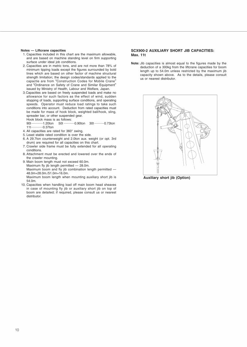
SCX900-2 AUXILIARY SHORT JIB CAPACITIES:Max. 11t
Note: Jib capacities is almost equal to the figures made by thededuction of a 300kg from the liftcrane capacities for boomlength up to 54.0m unless restricted by the maximum jibcapacity shown above. As to the details, please consultus or nearest distributor.
Auxiliary short jib (Option)

11
Fly Jib Capacities
���� �������
� � �������
���� �� ��� ����
���� ����
���� ���� ���� ���� ���� ���� ���� ����
�� �� �� �� �� �� �� �� �� �� �� �� �� �� �� ��
������������������������������������������������������������ �����
����!� ��
�����!������������ ������ ���������������������������������������
����!����
�����!������������������������ ����� �����������������������������������������
����!����
�������������������������� ��������������� �����������������
����!����
���!���� ����� ����������� ��������������������������� ����������� �������������
����!����
����!��� ����������������������������������������������������������������
�� �!����
����!���������� ������������������� �����������������������������������������������������
����!����
����!������������������ ��� �������������������������������������������������
����!����
�����!������������������������������������������� �����������������������������
����!����
�����!������������������� ����� ��� ����������� ������� �������������
����!����
�����!�������������������������� ������� ����������� ������������������� �������������
����!����������������������������������������������������������������
����!� ��
���!��� ��� ����������������������������������������������������������������� �����
����!����
����!���������� ��������������������������������������������������� �����
����!����
������ ���������������������������������������������������������������������
����!����
����!������������������ ���������������������������������������������
����!����
��������������������������������������������������������������������������������������������������������
���� ����� ��
� � ����� ��
���� �� ��� �� ��
���� ����
���� ���� ���� ���� ���� ���� ���� ����
�� �� �� �� �� �� �� �� �� �� �� �� �� �� �� ��
��������������������������������������������������������������������������������������������
���������������������������� �������������������������������������������
����!����
�����!����������������������� �������������������������������������������
����!����
�����!����������������������� � ����������������������������������� �����������������
����!����
����!������������ ��� ��������� ��������������� ����������������������� �
����!����
����!���������� ����� ����������������������������������������������������� �����
����!����
����!�������������� ����������������������������������������������� �����
����!�������������������������������������� ��������������� �����������������
����!����
����!������������������������������ ��� ����������������������� �����
�����!��������������������������� �����������������������������������������������
����!� ��
�����!��������������������� � ����� ��������������������������� ����������� �
����!� ��
�����!���������������������� ���������������������������������������������������
����!���
����!��� �������� � � ��������������������������������� �����������������
����!� �������������� � ����������������������������������������������� �����
����!����
����!���������������������������������������������� �����������������
����!����
����!�������������������������������������� �����������������������������
����!����
����!� ���������������������������� ��� �������������������������
����!����
���� ����� ��
� � ����� ��
���� �� ��� �� ��
���� ����
���� ���� ���� ���� ���� ���� ���� ����
�� �� �� �� �� �� �� �� �� �� �� �� �� �� �� ��
����������������������������������������������������������������������������������������
���������������������������� ����������������������������� ����������� �
����!����
�����!������������������ ��������� �������������������������������������
����!����
�����!���������������������� ��������� �������������������������������������
����!� ��
����!�������� ��� �����������������������������������������������
����!���
����!� �������������� ����� ���������������������������������������������
����!����
����!�������������� ��������������� �������������������������
����!����
����!��� ���������� ����������������������������������������������� �
����!����
������������������������������ ��� �����������������
����!����
�����!��������������������������� ������������� �����������������������������
����!����
�����!������������������ ��������� ������������������������������� �
����!����
������������ ����� �����������������������������������������������
����!�������� ��� �����������������������������������������������
����!������������ ��������������������������������� ����������� �
����!� ��
����!��� �������������������������� �������������������������
����!����
����!���������� ����������������������� �������������������������
����!���
����!������������������������������ ��� �����������������
����!����
12
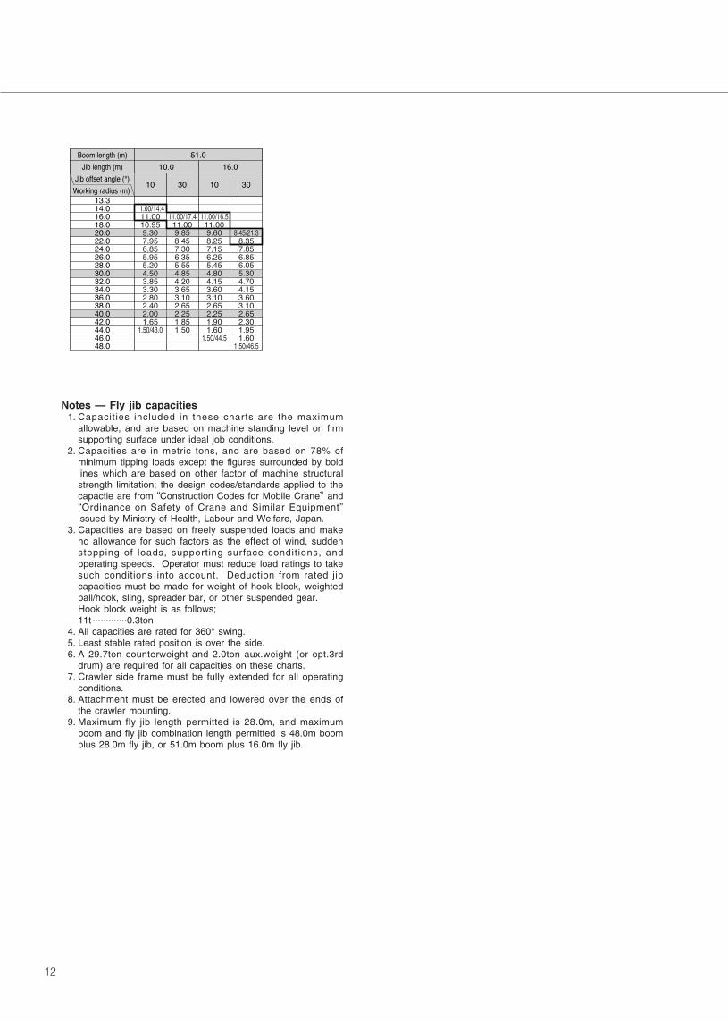
Notes — Fly jib capacities1. Capacities included in these charts are the maximum
allowable, and are based on machine standing level on firmsupporting surface under ideal job conditions.
2. Capacities are in metric tons, and are based on 78% ofminimum tipping loads except the figures surrounded by boldlines which are based on other factor of machine structuralstrength limitation; the design codes/standards applied to thecapactie are from “Construction Codes for Mobile Crane” and“Ordinance on Safety of Crane and Similar Equipment”issued by Ministry of Health, Labour and Welfare, Japan.
3. Capacities are based on freely suspended loads and makeno allowance for such factors as the effect of wind, suddenstopping of loads, supporting surface conditions, andoperating speeds. Operator must reduce load ratings to takesuch conditions into account. Deduction from rated jibcapacities must be made for weight of hook block, weightedball/hook, sling, spreader bar, or other suspended gear.Hook block weight is as follows;11t .............0.3ton
4. All capacities are rated for 360° swing.5. Least stable rated position is over the side.6. A 29.7ton counterweight and 2.0ton aux.weight (or opt.3rd
drum) are required for all capacities on these charts.7. Crawler side frame must be fully extended for all operating
conditions.8. Attachment must be erected and lowered over the ends of
the crawler mounting. 9. Maximum fly jib length permitted is 28.0m, and maximum
boom and fly jib combination length permitted is 48.0m boomplus 28.0m fly jib, or 51.0m boom plus 16.0m fly jib.
���� ����� ��
� � ����� ��
���� �� ��� �� ��
����
���� ����
�� �� �� ��
����������������������������������������������������������������������������
������������������ � ���!� ������� ���������������������������������
���������
�������!������� �������!�������������������������������������������
��������������� �������!������������������������������������� �����
���������
�������������!�����������������!����������������������� �����
���������
13
Liftcrane Working Ranges
60m Boom
57m Boom
54m Boom
51m Boom
70
65
60
55
50
40 440
48
51
54
57
60
45
42
39
36
33
30
27
24
21
10 25
12m Boom15m Boom
18m Boom21m Boom
24m Boom27m Boom
30m Boom33m Boom
36m Boom39m Boom
42m Boom45m Boom
48m Boom
5
5
5.0m
4.5m 4.
5m
Hook allowance height
15
12
Hei
ght a
bove
Gro
und
(m)
Boo
m L
engt
h (m
)
45
40
35
3515 20 30
Working Radius (m)
30
25
20
15
10
18
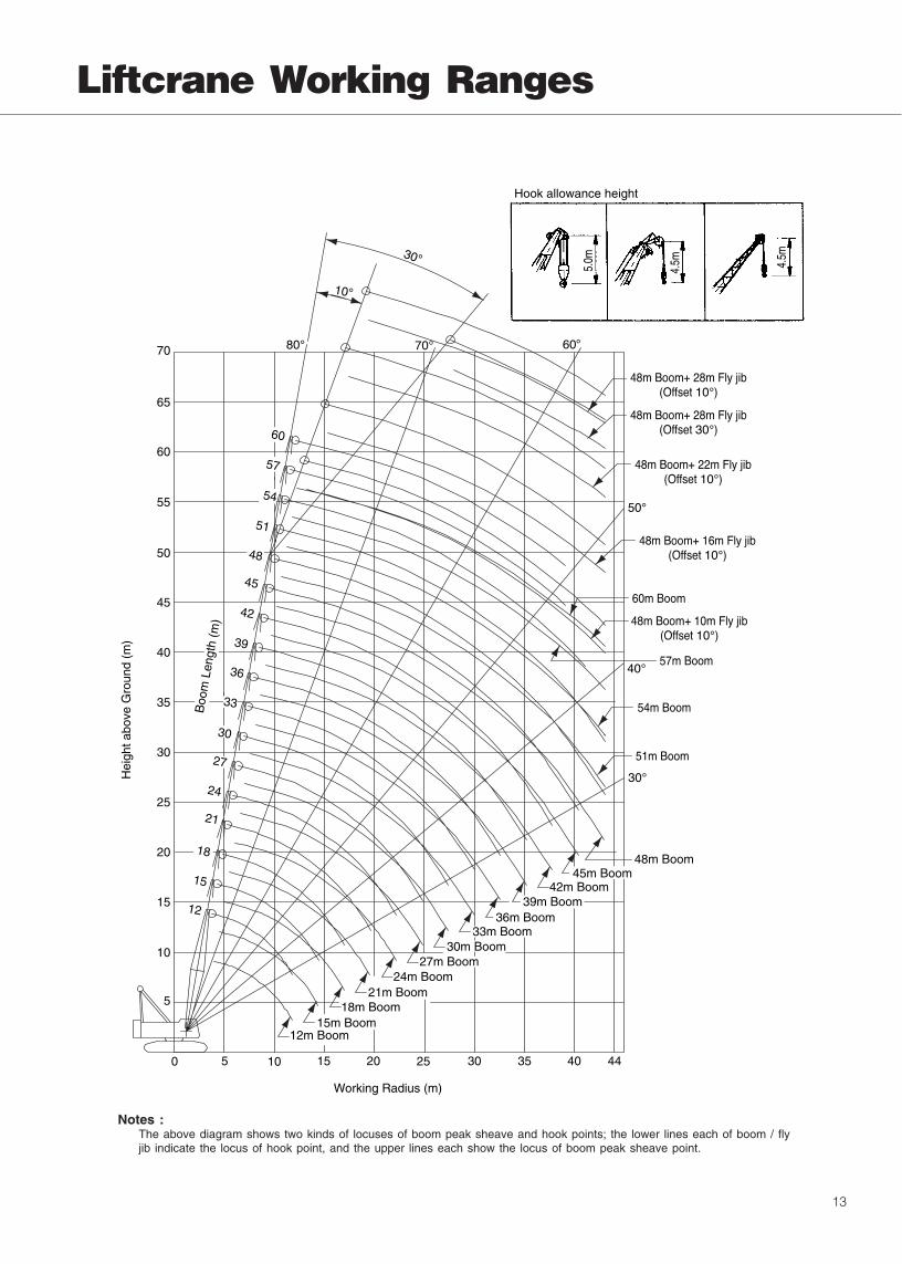
Notes :The above diagram shows two kinds of locuses of boom peak sheave and hook points; the lower lines each of boom / flyjib indicate the locus of hook point, and the upper lines each show the locus of boom peak sheave point.

14
Clamshell 2.0m3 over
5200
6575
3400
2100
1400
1250
53756295
Working radius
���� ����� ��
�� ���� ����� ������ ���� ���� ����
�� ��� �� �����
������������������������������
����������
�����������������������������������
����������
�����������������������������������������
����������
�����������������������������������������������
�� �������
�����������������������������������������
Notes:1. Max. clamshell rating is 10.0t.2. Mass of bucket plus load should not exceed clamshell ratings
shown above. Following data are for a general diggingapplication buckets.
3. Boom length shall not exceed 24.0m.4. Apparent specific gravity of lifting material:
Earth .................1.7~1.8t/m3
Gravel ...............1.8~2.0t/m3
5. High gantry is required and side frame must be fully extendedfor all operating conditions. Also, 29.7t counterweight and 2.0taux. weight are required for all clamshell ratings shown above.
6. Max. digging depth below ground shall be 36m.
Bucket capacityBucket mass
2.0m3 2.5m3
4.5t 5.5t
■CLAMSHELL RATINGS:
A
B
C
Bucket overall height (opened)
Bucket overall height (closed)
Bucket opening width
2.5m3
5.13
4.18
3.63
2.0m3
4.59
3.78
3.24
(in m)
Notes:1. Buckets of 2.0/2.5m3 are for a general excavating purpose.2. Other type of bucket than above is also available.
■BUCKET DIMENSIONS:
(in mm)
■WORKING MASS & GROUND PRESSURE:
Note: Working mass shown above is with 15.0m boom, 29.7toncounterweight, 2.0ton aux. weight, hydraulic tagline winderand 2.0m3/4.5t clamshell bucket.
���� ����� �� � ���� �
����� ����� ������� ������������
15
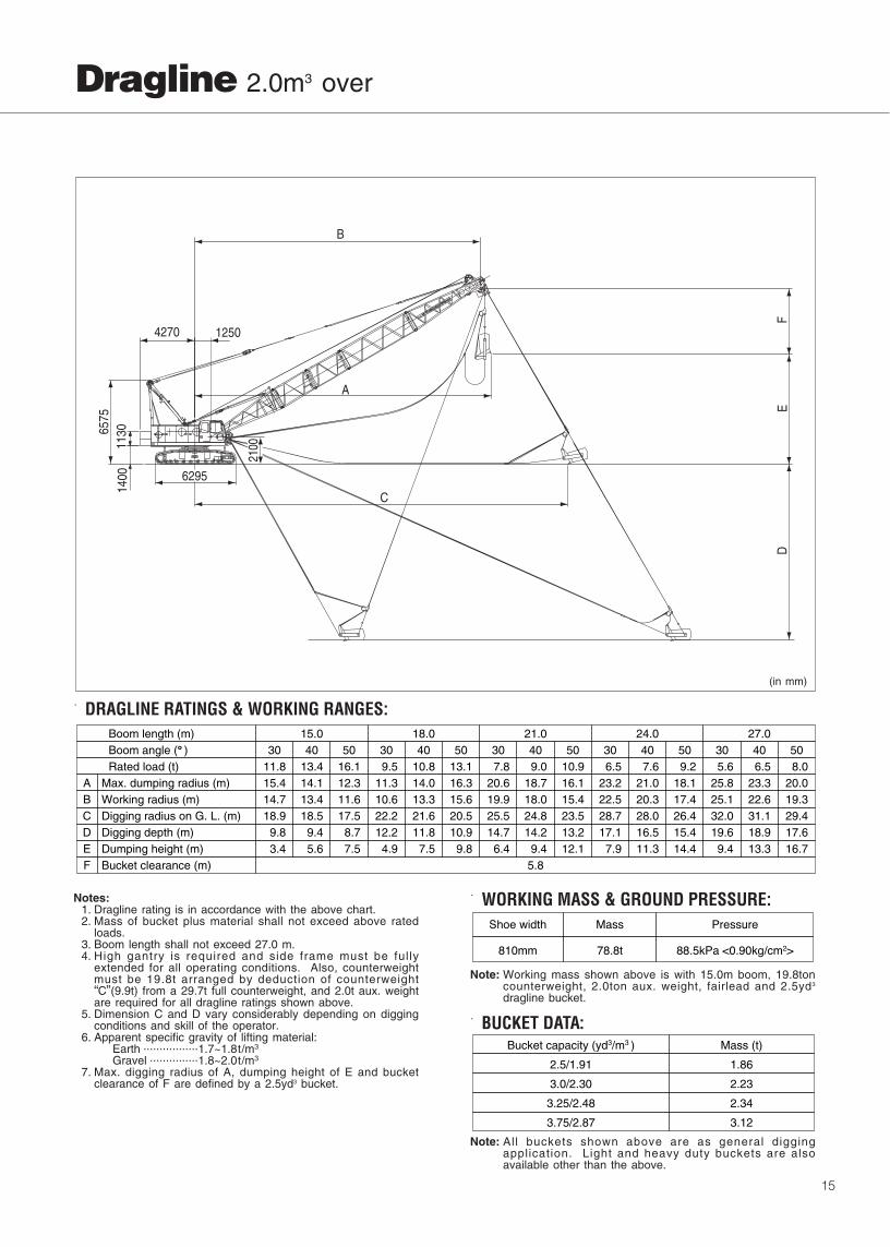
Notes:1. Dragline rating is in accordance with the above chart.2. Mass of bucket plus material shall not exceed above rated
loads.3. Boom length shall not exceed 27.0 m.4. High gantry is required and side frame must be fully
extended for all operating conditions. Also, counterweightmust be 19.8t arranged by deduction of counterweight“C”(9.9t) from a 29.7t full counterweight, and 2.0t aux. weightare required for all dragline ratings shown above.
5. Dimension C and D vary considerably depending on diggingconditions and skill of the operator.
6. Apparent specific gravity of lifting material:Earth .................1.7~1.8t/m3
Gravel ...............1.8~2.0t/m3
7. Max. digging radius of A, dumping height of E and bucketclearance of F are defined by a 2.5yd3 bucket.
■WORKING MASS & GROUND PRESSURE:
Note: Working mass shown above is with 15.0m boom, 19.8toncounterweight, 2.0ton aux. weight, fairlead and 2.5yd3
dragline bucket.
■BUCKET DATA:
Note: All buckets shown above are as general diggingapplication. Light and heavy duty buckets are alsoavailable other than the above.
■DRAGLINE RATINGS & WORKING RANGES:Boom length (m)Boom angle ( )Rated load (t)
A Max. dumping radius (m)B Working radius (m)C Digging radius on G. L. (m)D Digging depth (m)EF Bucket clearance (m)
Dumping height (m)5.8
16.112.311.617.5
8.77.5
13.414.113.418.5
9.45.6
11.815.414.718.9
9.83.4
(EC402251)
13.116.315.620.510.9
9.8
10.814.013.321.611.8
7.5
9.511.310.622.212.2
4.9
10.916.115.423.513.212.1
9.018.718.024.814.2
9.4
7.820.619.925.514.7
6.4
9.218.117.426.415.414.4
7.621.020.328.016.511.3
6.523.222.528.717.1
7.9
8.020.019.329.417.616.7
6.523.322.631.118.913.3
504030 504030 504030 504030 5040305.6
25.825.132.019.6
9.4
15.0 18.0 21.0 24.0 27.0
(in mm)
1400
113065
75
1250
2100
C
B
A
4270
ED
F
6295
Dragline 2.0m3 over
���� ����� �� � ���� �
����� ����� ������ ������������
Bucket capacity (yd3/m3 )
2.5/1.91
3.0/2.30
Mass (t)
1.86
2.23
3.25/2.48
3.75/2.87
2.34
3.12

16
General Dimensions
Note: 1. The above general arrangement is under liftcrane application with 12.0m basic boom, optional 90t hook block and optionalcarbody jack-up device.
2. When A-frame gantry is lowered, the dimension from center of rotation to the end of A-frame gantry is 5,200mm, and theheight from G.L. to the end of the gantry is 3,400mm.
(in mm)
4990(extended)3400(retracted)
300
425810
1805
3880
1600 1600
940
1945
1200
031
033
65
R4270
6575
1400
3400
1250
5375
6295
2100
1110

17
Standard equipment Optional equipment
Standard and Optional Equipment
Third drum winch;Third drum cable;Hyd. tagline winder; available for clamshellapplication;Fairlead; available for dragline application;Drum rollers; available on front/rear maindrums;Fire extinguisher;Catwalks with railings along both sides ofmachinery cab;Built-in type full air-conditioning;Anemometer; recommended for luffingtowercrane application;Re-fuel pump;Heater;Engine foot throttle;Electric cab fan.
Superstructure Isuzu 6HK1X diesel engine with an 212kW<288ps> rated output;Hydraulic system with three variabledisplacement axial piston pumps and one fixeddisplacement duplicate tandem gear pump;provided with aluminum-make oil cooler;Control system with one each of quadruplicateand triplicate tandem valves and pilot-operatedarm chair single axis control levers; providedwith motorcycle type “EPC” controller (easy-precise-minute engine rpm and hyd. pump oilflow control device), and specially-tailoredpressure compensating valves;Front and rear main operating drum winchesof 196kN〈 20t〉 line pull with 554mm dia.drum lagging driven by independent variabledisplacement hyd. motor ; provided withmultiple wet-disc type brake installed withindrum inside together with reduction gear unitwith negative brake design, brake releasecontrol under dynamic hyd. pressure, and aforced-oil cooling system. In addition, drumrotation speed control and drum rotationsensor are also provided. Available to operatein two brake modes of automatic and free-fall;Boom hoist mechanism driven by hyd. motorwith automatic brake; provided with drum rotationspeed control and drum rotation sensor;Swing mechanism with turntable bearing;driven by two hyd. motor w/spring-applied,power hydraulically released multiple wet-discbrake; provided with speed control device;Power hydraulically retractable A-frame gantry;940mm wide, full-vision operator’s cab with astamped-and-rounded corner design and largefront window; provided with an arrangement ofarmchair operator control station andinstrument panel;29.7ton counterweight;2.0ton auxiliary weight; if opt. 3rd drum winchis required, this aux. weight is not furnished;Machinery cab with hinged doors;24-volt electrical system with two 12-volt batteries;Lighting system:Two 70W working lights;One 10W interior cab light;
Accessories:AM/FM radio w/clock;Engine hourmeter; Engine tachometer ;indicated on displaypanel of LMI;Fuel gauge;Eng. water temp. gauge;Engine over-heat indicator ; available ondisplay panel of LMI;Hyd. oil over-temp. indicator; available ondisplay panel of LMI;Brake oil over-temp. indicator; available ondisplay panel of LMI;24V electric outlet;Dual, intermittent window shield wipers withwashers; available on both front and roofwindows;Cigar lighter;Ash tray;Book holder;Sunvisor;Sunshade;Cup Holder;Non-skid surfaces;Cab front step;Cab sidestep;Cab floor mat;Superstructure under-cover.
Std. spare parts and tools.

18
Standard equipment Optional equipment
Undercarriage 4,180mm gauge by 6,295mm long crawlerlower with power hydraulically retractable/extendible crawler side frames;Crawler drive units with shoe-in type tractionmotor with wet-disc type automatic brakes;810mm wide track shoes;Manual track tension adjusting devices;Lifetime lubricated track components;Crawler side steps.
Liftcrane Att. 12.0m basic bom; 6.0m bottom section, and6.0m tapered top section;Four boom head sheaves w/two guide sheavesand rigid type cable guard;Bail and bridle assemblies;Main crane hoist cable; 26mm dia./200m long;Boom hoist cable; 22.4mm dia./160m long.
Note:In case of dragline and clamshell applications, a15.0m boom of 12.0m basic plus one opt. 3.0mboom extension is recomennded as minimumlength of boom.
Carbody jack-up device w/4-vertical hyd.jack-up cylinder and remote control unit;Automatic track tension adjusting device,i/o manual one as std.
3.0m boom extension;
6.0m boom extension;
9.0m boom extension;
10.0m basic fly jib; 5.0m bottom and topsections with strut and guyline pendants;
6.0m fly jib extension;
Auxiliary short jib;
90t duplex type hook block;
50t hook block;
30t hook block;
11t ball hook;
Aux. crane hoist cable, 26mm dia./170mlong;
Heavy duty, single head sheave w/a guidesheave and roller type rope guard;available for exclusive dragline application;
Boom skywalk; available for all sections ofliftcrane main boom.
19
Standard equipment Optional equipment
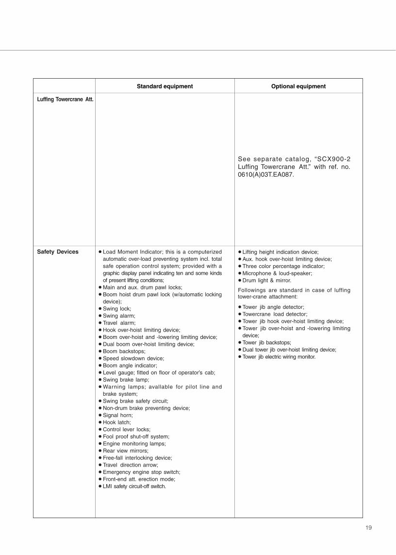
Luffing Towercrane Att.
Safety Devices Load Moment Indicator; this is a computerizedautomatic over-load preventing system incl. totalsafe operation control system; provided with agraphic display panel indicating ten and some kindsof present lifting conditions;Main and aux. drum pawl locks;Boom hoist drum pawl lock (w/automatic lockingdevice);Swing lock;Swing alarm;Travel alarm;Hook over-hoist limiting device;Boom over-hoist and -lowering limiting device;Dual boom over-hoist limiting device;Boom backstops;Speed slowdown device;Boom angle indicator;Level gauge; fitted on floor of operator’s cab;Swing brake lamp;Warning lamps; avallable for pilot line andbrake system;Swing brake safety circuit;Non-drum brake preventing device;Signal horn;Hook latch;Control lever locks;Fool proof shut-off system;Engine monitoring lamps;Rear view mirrors;Free-fall interlocking device;Travel direction arrow;Emergency engine stop switch;Front-end att. erection mode;LMI safety circuit-off switch.
See separate catalog, “SCX900-2Luffing Towercrane Att.” with ref. no.0610(A)03T.EA087.
Lifting height indication device;Aux. hook over-hoist limiting device;Three color percentage indicator;Microphone & loud-speaker;Drum light & mirror.
Followings are standard in case of luffingtower-crane attachment:
Tower jib angle detector;Towercrane load detector;Tower jib hook over-hoist limiting device;Tower jib over-hoist and -lowering limitingdevice;Tower jib backstops;Dual tower jib over-hoist limiting device;Tower jib electric wiring monitor.
• We are constantly improving our products and therefore reserve the right to change designs and specifications without notice.• Units in this specification are shown under International System of Units; the figures in parenthesis are under GravitationalSystem of Units as old one.
Printed in Japan0610(A)03T.EA086
(Supersedes 0405(A)02T.EA024-)
Address Inquires to:
SCX900-2

3
w/26.5mTower���� ����
�� �� �� �� �� �� �� ��
����
����
����
�����
�����
�����
����
����
�����
�����
�����
�����
�����
����
�����
�����
����
����
���
����
���
�����
�����
�����
�����
�����
�����
�����
�����
���
����
�����
�����
���������
��������
���
����
����
�����
����
����
��������
���������
����
����
����
��������
���������
���
��
���
���������
�����
�����
�����
�����
�����
�����
���
����
�����
����
����
��������
���������
����
�����
����
����
����
����
���
�������
��������
����
���
����
����
���
�������
������
��
���
���
���
������ ���������
��� ���� !���
w/29.5m Tower���� ���� ����
�� �� �� �� �� �� �� �� �� �� �� ��
���
���
���
����
����
����
���
���
����
����
����
����
����
���
����
����
���
���
��
���
���
���
���
�����
�����
�����
�����
�����
�����
�����
�����
���
����
�����
����
���������
��������
����
�����
����
����
����
����
�������
����
����
����
����
��������
������
���
���
�������
���������
�����
�����
�����
�����
�����
�����
���
����
�����
����
����
��������
���������
�����
����
����
����
����
���
���������
�������
����
����
����
���
�����
�������
���
��
���
������
���������
�����
�����
�����
�����
�����
����
���
�����
�����
����
����
���
���������
����������
�����
����
����
����
����
����
����
�������
��������
���
���
���
���
���
�������
�����
��
���
����
����
� ����� ������ ���
��� ����� ���
Luffing Towercrane Capacities
4
w/32.5m Tower���� ���� ���� ����
�� �� �� �� �� �� �� �� �� �� �� �� �� �� �� ��
���
���
���
����
����
����
���
���
����
����
����
����
����
���
����
����
���
���
��
���
���
���
���
��
���
�����
�����
�����
�����
�����
�����
�����
�����
���
����
�����
����
��������
����������
�����
�����
����
����
����
����
���������
�������
����
���
���
������
�������
���
���
���
�������
��������
�����
�����
�����
�����
�����
�����
���
����
�����
����
����
��������
����������
�����
����
���
����
����
����
��������
���������
����
���
���
��
���
������
�����
���
���
����
��������
���������
�����
�����
�����
�����
�����
�����
���
���
�����
�����
����
����
���
���������
����������
���
���
���
����
����
����
����
�������
��������
����
���
��
���
���
������
��������
����
����
����
���
��������
���������
�����
�����
�����
�����
�����
����
���
�����
�����
����
����
����
����
���������
���������
���
����
���
����
����
���
����
���
������
��������
��
���
���
���
���
���
��������
��������
����
���
����
����
����
� ����� ������ ���
��� ����� ���
������� ���� � �
���
���
���
����
����
����
����
����
����
����
����
����
����
����
����
����
����
����
����
����
����
����
����
����
����
����
�����
�����
�����
�����
�����
�����
�����
�����
�����
�����
�����
�����
���������
����������
�����
����
����
����
����
���������
���������
����
����
����
����
���������
���������
����
����
����
���������
���������
�����
�����
�����
�����
�����
�����
�����
�����
�����
�����
����
���������
����������
�����
����
����
����
����
����
����
���������
����
����
����
����
���������
���������
����
����
����
���������
���������
�����
�����
�����
�����
�����
�����
�����
�����
�����
�����
����
����
����
���������
����������
����
����
����
����
����
����
����
���������
���������
����
����
����
����
����
���������
���������
����
����
����
����
���������
���������
�����
�����
�����
�����
�����
�����
�����
�����
�����
����
����
����
����
���������
���������
����
����
����
����
����
����
����
����
���������
���������
����
����
����
����
����
����
���������
���������
����
����
����
����
���������
����������
�����
�����
�����
�����
�����
�����
�����
�����
����
����
����
����
����
����
���������
���������
����
����
����
����
����
����
����
����
����
���������
���������
����
����
����
����
����
����
����
���������
���� ���� ���� ���� ����
�� �� �� ��� �� �� �� ��� �� �� �� ��� �� �� �� ��� �� �� �� ��
��� ���� ! � �
w/35.5m Tower
���������
����
����
����
����

5
������� ���� � �
���
���
���
����
����
����
����
����
����
����
����
����
����
����
����
����
����
����
����
����
����
����
����
����
����
����
����
�����
�����
�����
�����
�����
�����
�����
�����
�����
�����
�����
�����
���������
����������
�����
����
����
����
����
���������
���������
����
����
����
���� ���������
����
����
����
���������
�����
�����
�����
�����
�����
�����
�����
�����
�����
�����
����
���������
�����
����
����
����
����
����
����
���������
���������
����
����
����
����
����
���������
���������
����
����
����
���������
�����
�����
�����
�����
�����
�����
�����
�����
�����
�����
����
����
����
���������
���������
����
����
����
����
����
����
����
���������
���������
����
����
����
����
����
���������
���������
����
����
����
���������
���������
�����
�����
�����
�����
�����
�����
�����
�����
�����
����
����
����
����
���������
���������
����
����
����
����
����
����
����
����
���������
���������
����
����
����
����
����
����
���������
���������
����
����
����
����������
�����
�����
�����
�����
�����
�����
�����
����
����
����
����
����
����
����
���������
���������
����
����
����
����
����
����
����
����
����
���������
���������
����
����
����
����
����
����
���������
����������
�����
�����
�����
�����
�����
�����
�����
����
����
����
����
����
����
����
����
���������
���������
����
����
����
����
����
����
����
����
����
����
���������
���������
����
����
����
����
����
����
����
����
���� ���� ���� ���� ���� ����
�� �� �� ��� �� �� �� ��� �� �� �� ��� �� �� �� ��� �� �� �� �� �� ��
��� ���� ! � �
w/38.5m Tower
������� ���� � �
���
���
���
����
����
����
����
����
����
����
����
����
����
����
����
����
����
����
����
����
����
����
����
����
����
����
����
�����
�����
�����
�����
�����
�����
�����
�����
�����
�����
�����
�����
���������
����������
�����
����
����
����
����
����
���������
���������
����
����
����
����
��������� ���������
����
����
���������
���������
�����
�����
�����
�����
�����
�����
�����
�����
�����
�����
����
���������
���������
����
����
����
����
����
����
���������
���������
����
����
����
����
��������� ���������
����
����
����
���������
�����
�����
�����
�����
�����
�����
�����
�����
�����
�����
����
����
����
���������
���������
����
����
����
����
����
����
����
���������
���������
����
����
����
����
����
���������
���������
�����
�����
�����
�����
�����
�����
�����
�����
�����
����
����
����
����
���������
���������
����
����
����
����
����
����
����
����
���������
����
����
����
����
����
����
���������
����������
�����
�����
�����
�����
�����
�����
�����
����
����
����
����
����
����
����
���������
���������
����
����
����
����
����
����
����
����
����
���������
���������
����
����
����
����
����
����
����
���������
����������
�����
�����
�����
�����
�����
�����
�����
����
����
����
����
����
����
����
����
���������
���������
����
����
����
����
����
����
����
����
����
����
���������
���������
����
����
����
����
����
����
����
����
���������
����
����
����
����
����
����
����
����
����
����
����
����
����
����
����
����
���������
���������
����
����
����
����
����
����
����
����
����
����
���������
���� ���� ���� ���� ���� ���� ����
�� �� �� ��� �� �� �� ��� �� �� �� �� �� �� �� �� �� �� �� �� �� ��
��� ���� ! � �
w/41.5m Tower
6
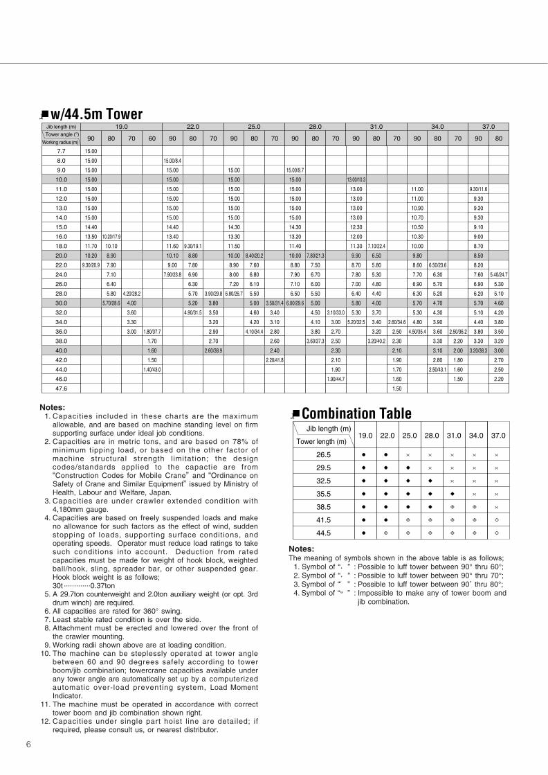
Notes:1. Capacities included in these charts are the maximum
allowable, and are based on machine standing level on firmsupporting surface under ideal job conditions.
2. Capacities are in metric tons, and are based on 78% ofminimum tipping load, or based on the other factor ofmachine structural strength l imitation; the designcodes/standards applied to the capactie are from“Construction Codes for Mobile Crane” and “Ordinance onSafety of Crane and Similar Equipment” issued by Ministry ofHealth, Labour and Welfare, Japan.
3. Capacities are under crawler extended condition with4,180mm gauge.
4. Capacities are based on freely suspended loads and makeno allowance for such factors as the effect of wind, suddenstopping of loads, supporting surface conditions, andoperating speeds. Operator must reduce load ratings to takesuch condit ions into account. Deduction from ratedcapacities must be made for weight of hook block, weightedball/hook, sling, spreader bar, or other suspended gear.Hook block weight is as follows;30t .............0.37ton
5. A 29.7ton counterweight and 2.0ton auxiliary weight (or opt. 3rddrum winch) are required.
6. All capacities are rated for 360° swing.7. Least stable rated condition is over the side.8. Attachment must be erected and lowered over the front of
the crawler mounting.9. Working radii shown above are at loading condition.
10. The machine can be steplessly operated at tower anglebetween 60 and 90 degrees safely according to towerboom/jib combination; towercrane capacities available underany tower angle are automatically set up by a computerizedautomatic over-load preventing system, Load MomentIndicator.
11. The machine must be operated in accordance with correcttower boom and jib combination shown right.
12. Capacities under single part hoist l ine are detailed; ifrequired, please consult us, or nearest distributor.
������� ���� � �
���
���
���
����
����
����
����
����
����
����
����
����
����
����
����
����
����
����
����
����
����
����
����
����
����
����
�����
�����
�����
�����
�����
�����
�����
�����
�����
�����
�����
�����
���������
����������
�����
����
����
����
����
����
���������
���������
����
����
����
���� ���������
����
����
����
���������
���������
�����
�����
�����
�����
�����
�����
�����
�����
�����
�����
����
���������
���������
����
����
����
����
����
����
���������
���������
����
����
����
����
����
���������
�����
�����
�����
�����
�����
�����
�����
�����
�����
�����
����
����
����
���������
���������
����
����
����
����
����
����
����
���������
���������
����
����
����
����
����
���������
���������
�����
�����
�����
�����
�����
�����
�����
�����
�����
����
����
����
����
���������
���������
����
����
����
����
����
����
����
����
���������
���������
����
����
����
����
����
����
���������
����������
�����
�����
�����
�����
�����
�����
�����
����
����
����
����
����
����
����
���������
���������
����
����
����
����
����
����
����
����
����
���������
���������
����
����
����
����
����
����
����
�����
�����
�����
�����
�����
�����
�����
����
����
����
����
����
����
����
����
���������
���������
����
����
����
����
����
����
����
����
����
����
���������
���������
����
����
����
����
����
���������
����
����
����
����
����
����
����
����
����
����
����
����
����
����
����
����
���������
���������
����
����
����
����
����
����
����
����
����
����
����
���� ���� ���� ���� ���� ���� ����
�� �� �� ��� �� �� �� �� �� �� �� �� ��� �� �� ��� �� �� �� �� ��
��� ���� ! � �
w/44.5m Tower
Jib length (m)
Tower length (m)19.0 22.0 25.0 28.0 31.0 34.0 37.0
26.5
29.5
32.5
35.5
38.5
41.5
44.5
●
●
●
●
●
●
●
×
●
●
●
●
◎
◎
●
●
●
●
●
●
◎
×
×
●
●
●
◎
◎
×
×
×
●
◎
◎
◎
×
×
×
×
◎
◎
◎
×
×
×
×
×
○
○
Combination Table
Notes:The meaning of symbols shown in the above table is as follows;
1. Symbol of “●” : Possible to luff tower between 90° thru 60°;2. Symbol of “◎” : Possible to luff tower between 90° thru 70°;3. Symbol of “◯” : Possible to luff tower between 90˚ thru 80°;4. Symbol of “×” : Impossible to make any of tower boom and
jib combination.


![[Drum] Colin Bailey - Bass Drum Control](https://img.dokumen.tips/doc/110x75/5571f30449795947648d5ee9/drum-colin-bailey-bass-drum-control.jpg)