Embed Size (px)
Citation preview

Operation Manual
Scroll pumps
Types scrollvac S 10 scrollvac S 15
460004 2010-01-05
We are constantly working on the further development of all our product types. Reprinting or reproduction of this manual, including extracts, is not allowed without the prior written permission of ILMVAC GmbH. All rights under the copyright laws are expressly reserved by ILMVAC GmbH. We reserve the right to make changes and amendments. ILMVAC GmbH Am Vogelherd 20 D-98693 Ilmenau Tel.: +49 3677 - 604 0 Fax: +49 3677 - 604 110 [email protected] www.ilmvac.de www.ilmvac.com
Contents
Contents 1 Important Information........................................................................................................................... 4 1.1 General Information ................................................................................................................................ 4 1.2 Target Groups......................................................................................................................................... 4 1.3 Intended Use........................................................................................................................................... 4 1.4 Use for an Unauthorized Purpose........................................................................................................... 4 1.5 Safety Devices ........................................................................................................................................ 5 1.6 Meaning of the Warning notes ................................................................................................................ 5 1.7 Product Standards, Safety Regulations .................................................................................................. 5 2 Basic Safety Instructions ..................................................................................................................... 6 2.1 General Information ................................................................................................................................ 6 2.2 Electricity................................................................................................................................................. 6 2.3 Mechanical Systems ............................................................................................................................... 6 2.4 Hazardous Substances ........................................................................................................................... 7 2.5 High Temperatures ................................................................................................................................. 7 3 Description ............................................................................................................................................ 8 3.1 Design..................................................................................................................................................... 8 3.2 Area of Application.................................................................................................................................. 9 3.3 Function .................................................................................................................................................. 9 3.3.1 Working Principle .................................................................................................................................... 9 3.3.2 Vapour pressure tolerance.................................................................................................................... 10 3.3.3 Dry-running sealing and sealing systems.............................................................................................. 10 3.3.4 Basic chemical resistance..................................................................................................................... 10 3.4 Standard accessories............................................................................................................................ 11 3.4.1 Overview and order numbers................................................................................................................ 11 3.4.2 Intake filter, helium tight OMEH 30/25................................................................................................... 12 3.4.3 Condensate separator PT 25 ................................................................................................................ 12 3.4.4 Condenser SKS 40/25 .......................................................................................................................... 12 3.4.5 Cooling Trap welded and dismounted................................................................................................... 12 3.4.6 Vacuum valves...................................................................................................................................... 12 3.5 Scope of Delivery.................................................................................................................................. 12 4 Technical Data..................................................................................................................................... 13 4.1 View of device and dimensions............................................................................................................. 13 4.2 Intake Pressure / Pumping Speed – Diagram ....................................................................................... 14 4.3 Device data ........................................................................................................................................... 14 5 Installation and Operation.................................................................................................................. 15 5.1 Unpacking ............................................................................................................................................. 15 5.2 General references ............................................................................................................................... 15 5.3 Installation and Connection................................................................................................................... 15 5.4 Connecting to the electricity supply....................................................................................................... 16 5.4.1 Type of motor protection ....................................................................................................................... 16 5.4.2 Selection of the protection..................................................................................................................... 17 5.5 Operation .............................................................................................................................................. 17 5.5.1 Starting-up ............................................................................................................................................ 17 5.5.2 Operation to pump out condensable vapours ....................................................................................... 18 5.5.2.1 Resistance chart ................................................................................................................................... 19 5.5.3 Closing down ........................................................................................................................................ 19 5.6 Storage ................................................................................................................................................. 19 5.7 Scrap Disposal...................................................................................................................................... 19 6 Maintenance and Servicing................................................................................................................ 20 6.1 Maintenance Performed by the User .................................................................................................... 20 6.1.1 Replacing the special sliding seals ....................................................................................................... 20 6.2 Maintenance by the Manufacturer......................................................................................................... 22 6.3 Damage Report..................................................................................................................................... 22 7 Troubleshooting.................................................................................................................................. 23 8 Overview of spare parts ..................................................................................................................... 24 8.1 Maintenance kit ..................................................................................................................................... 24 8.2 View of spare part ................................................................................................................................. 25 8.2.1 List of spare parts ................................................................................................................................. 26
460004 Ilmvac GmbH 3

Important Information
1 Important Information
1.1 General Information The ILMVAC Scroll Pumps conform to the following directives: • 2006/95/EC Low Voltage Directive • 2006/42/EC Machinery Directive • 2004/108/EC Electromagnetic Compatibility Directive The CE sign is located on the rating plate. Observe the binding national and local regulations when fitting the pump into installations. Our products are sold worldwide and can therefore be equipped with the typical national plugs and for the various voltages. You will find more information about the available pump designs under http://www.ilmvac.de.
1.2 Target Groups This Operating Manual is intended for the personnel planning, operating and maintaining ILMVAC Scroll Pumps. This group of people includes: • Designers and fitters of vacuum apparatus, • Employees working on commercial laboratory and industrial vacuum technology applica-
tions and • Service personnel for scroll pumps. The personnel operating and maintaining the scroll pumps must have the technical compe-tence required to perform the work that has to be done. The user must authorize the operating personnel to do the work that has to be done. The personnel must have read and understood the complete Operating Manual before using the scroll pumps. The Operating Manual must be kept at the place of use and be available to the personnel when required.
1.3 Intended Use • The layout of the scroll pump must be appropriate for the conditions of use. The user
bears the sole responsibility for this. • The scroll pump may only be operated under the conditions stated
– in the "Technical Data" section, – on the type plate, and – in the technical specification for the order concerned.
1.4 Use for an Unauthorized Purpose It is forbidden to use the pump for applications deviating from the technical data stated on the type plate or the conditions stated in the supply contract, or to operate it with missing or defective protective devices.
4 Ilmvac GmbH 460004

Important Information
1.5 Safety Devices Measures such as the following are for the safety of the operating personnel: • electrical connection with a protective conductor (operating mode S1) and an earthing
plug, • Motor protection switch (thermal) and • “Hot Surface" label on the pump body (warning notice). The scroll pump must not be operated without these elements.
1.6 Meaning of the Warning notes Take note of the warning notes. They are in the following box:
CAUTION ! / WARNING !
Hazard which may lead to serious injuries or material damage.
1.7 Product Standards, Safety Regulations ILMVAC Scroll Pumps meet the following product standards:
DIN EN 292-1, DIN EN 292-2 Safety of machines, basic terminology DIN EN 1012-2 Compressors and vacuum pumps DIN EN 60204-1 Electrical equipment of machines EN 50110-1 (DIN VDE 0105-100) Operation of electrical installations EN 61010-1 Safety for laboratory devices EN 50081-1-2 Electromagnetic compatibility (EMC)
Generic specification - Interference resistance for residential, business and industrial areas, and small businesses
EN 50082-1-2 Electromagnetic compatibility (EMC) Generic specification - Interference emission for residential, business and industrial areas, and small businesses
EN 55014 Radio disturbance characteristics of electrical equipment and systems
EN 61000-3-2/3 Electromagnetic compatibility (EMC)
Directive 2006/42/EC Law and Administration Regulations relating to Machinery Directive 2002/95/EC RoHS Restriction of use of certain hazardous substances
The following additional safety regulations apply in the FR Germany:
BGV A2 Electrical equipment and operating materials VBG 5 Power-driven machines BGR 120 Guidelines for laboratories BGI 798 BG hazard assessment in the laboratory
Observe the standards and regulations applying in your country when you use the scroll pumps.
460004 Ilmvac GmbH 5

Basic Safety Instructions
2 Basic Safety Instructions
2.1 General Information Warning notices must be observed. Disregarding them may lead to damage to health and property. The scroll sumps must be operated by personnel who can detect impending dangers and take action to prevent them from materialising. The manufacturer or authorized authorised workshops will only service or maintain the scroll pump if it is accompanied by a fully completed damage report. Precise information about the contamination (also negative information if necessary) and thorough cleaning of the Scroll Pump are legally binding parts of the contract. Contaminated scroll pumps and their individual parts must be disposed of in accordance with the legal regulations. The local regulations apply in foreign countries.
2.2 Electricity Scroll pumps of operation mode S1 are supplied. Please note that the testing must be re-peated in accordance with DIN EN 0105, DIN EN 0702 and BGV A 2 in case of portable de-vices of operation mode S1. The local regulations apply in foreign countries. Please note the following when connecting to the electrical power supply system: • The electrical power supply system must have a protective connector according to DIN
VDE 0100-410 (IEC 60364-4-41). • The protective connector must not have any breaks. • The connecting cable must not be damaged.
2.3 Mechanical Systems Improper use can lead to injuries or material damage. Observe the following instructions:
• Only operate the scroll pumps with the specified flange-mounting components. • Hazardous substances must be separated out as far as this is technically possible before
they reach the pump. • External mechanical stresses and vibrations must not be transmitted to the pump. Only
use flexible vacuum hoses for connecting scroll sumps. • The pump must not be used to suck up fluids. Lay the exhaust pipe so that it slopes
downwards, so allowing condensate to flow out of the pump. Collect the condensate and dispose of it in an environmentally compatible manner.
• Maintain a space of least 20 cm between the pump and adjacent parts in order to enable the pump to cool.
CAUTION !
Solid particles in the pumping medium impair the pumping action and can lead to damage. Prevent solid particles penetrating into the pump!
6 Ilmvac GmbH 460004

Basic Safety Instructions
2.4 Hazardous Substances The operating company bears the responsibility for the use of the scroll pump. Hazardous substances in the gases to be pumped can cause personal injuries and property damage. Pay attention to the warning notices for handling hazardous substances. The local regulations apply in foreign countries. Combustible Gases Examine before switching on whether that can form gas combustible gas/air mixtures which can be promoted! Consider the regulations of the guideline 1999/92 EC. Aggressive gases or vapours As indicated in the resistance chart in chapter 5.5.2.1, scroll pumps are conditionally suitable for pumping aggressive gases or vapours. Poisonous gases Use a separator when pumping poisonous or harmful gases. Prevent such substances from leaking out of the appliance or pump. Treat these substances according to the applicable environmental protection regulations. Test the strength and leak-tightness of the connecting lines and the connected apparatus. Prevent environmental poisons, e.g. mercury, getting into the scroll pumps. Fulfil the requirements, for example: • German Hazardous Substances Regulation (GefStoffV) of 23. December 2004 • Regulations 2006/121/EC (classification, packaging and identification of hazardous sub-
stances), • Manufacturer's safety data sheets on hazardous substances.
2.5 High Temperatures The scroll pump may heat up as a result of the temperature of the gas being pumped and through intrinsic heating. The temperature of the scroll pump heads can reach 50 °C during operation. Prevent the following maximum permissible temperatures from being exceeded. • + 40 °C for the environment, and • + 20 °C for the gas to be pumped. The motor is protected against overload by a protective switch.
460004 Ilmvac GmbH 7

Description
3 Description
3.1 Design ILMVAC’s scrollvac S 10 and scrollvac S 15 Scroll Pumps a dry-running vacuum pump in spiral design. The pumping speed is 10 m3 ⋅ h-1 and/or 15 m3 ⋅ h-1. The pump drive with a special-purpose built-in motor is flanged directly to the pump casing top part. The scroll rotor is fastened to the solid motor or pump shaft which runs on anti-friction bearings. The stationary counter spiral to the scroll rotor is located in the stator. A fan located under the stator is used for cooling. The entire pump consisting of drive, pump casing top part, and stator is mounted vertically to the plastic base and its recessed handles.
1 - Drive 2 - Pump casing - upper part 3 - Stator complete 3.1 - Fan 4 - Foot complete 4.1 - Recessed grips 5 - On / Off switch 6 - Suction port 7 - Pressure and/or
exhaust port 8 - Screw plug
for inert gas connection
Fig. 1 Scroll pump
9 - Type plate
1 7; 9
5
4.1
4
6 8 2; 3; 3.1
The Scroll pump has the following features:
• Compact vertical design • silent and low-vibration operation • continuous operation even with high intake pressures • Suction and exhaust ports are designed with small flanges according to DIN 28403 • Important parts are easy to service and replace Special features : • The vertical design, and the omission of the working valve or exhaust valve ensure the
smooth drainage of any condensate forming inside the pump, thus avoiding damage to the pump.
• A specific surface coating of the parts which are in contact with the fluid guarantees that the pump has a basic chemical resistance as specified in the resistance chart in chapter 5.5.2.1. In addition, the coating provides the required sliding properties in combination with the sealing strip inserted at the front side of the spirals.
• All static seals (e.g., O-rings) are made of either Viton or EPDM.
8 Ilmvac GmbH 460004
Description
3.2 Area of Application The field of application covered by the dry-running scroll pump covers the whole range of vacuum technology both in laboratory and in industrial applications. The function of the scroll pump is to generate an ultimate pressure of up to 7 ⋅ 10-2 mbar • either as a single pump, or • as a fore-pump for turbo-molecular pumps. The scroll pump can be used to pump biological, toxic, and radioactive gases or vapours as indicated in the resistance chart in chapter 5.5.2.1, and evacuate containers or vacuum sys-tems up to the high vacuum range.
CAUTION !
The scroll pump must not be used for extracting explosive gases or vapours.
The scroll pump must not be operated in rooms which might contain explosive gases and vapours!
3.3 Function
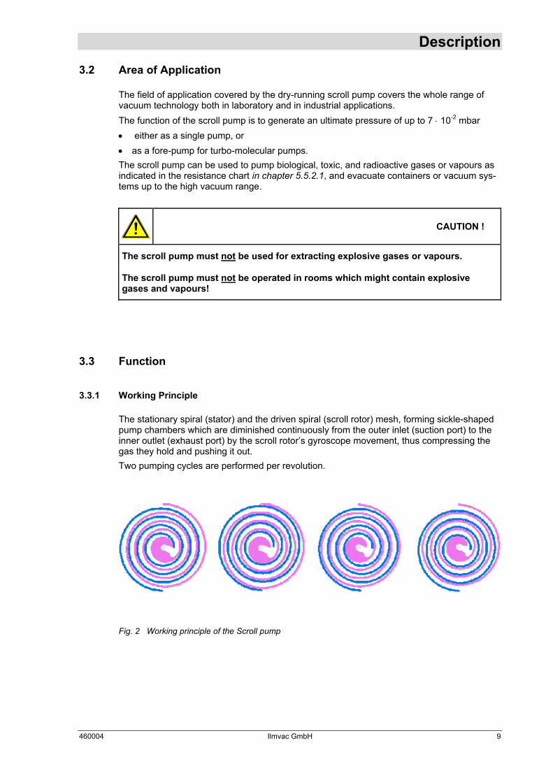
3.3.1 Working Principle The stationary spiral (stator) and the driven spiral (scroll rotor) mesh, forming sickle-shaped pump chambers which are diminished continuously from the outer inlet (suction port) to the inner outlet (exhaust port) by the scroll rotor’s gyroscope movement, thus compressing the gas they hold and pushing it out. Two pumping cycles are performed per revolution.
Fig. 2 Working principle of the Scroll pump
460004 Ilmvac GmbH 9
Description 3.3.2 Vapour pressure tolerance
The scroll pump has a vapour pressure tolerance of 50 mbars (measured for water). This is a very good value for scroll pumps, and it has been achieved by the following design fea-tures: • Vertical installation of drive or pump shaft, and consequent horizontal position of
scroll or pump rotor: Any condensates which might accumulate in the pump can drain without any problem from the stator and rotor system through the discharge port.
• No working valve or exhaust valve: Vapours can pass freely through the discharge port without being condensated by the opening pressure of an upstream exhaust valve.
• Gas ballast system: The condensation of vapours is reduced by feeding in ambient air (gas ballast) during the compression process. Inert gases (N2, Ar) can be used as gas ballast for special applica-tions. The scroll pump is always working with gas ballast.
3.3.3 Dry-running sealing and sealing systems The dry-running sealing of the rotor-stator arrangement is obtained both by the coating of the metal parts, and by a special sealing strip. An optimum match is achieved between both fric-tion partners in this combination. The sealing system consists of the spiral-shaped sealing strip used to pack the pump cham-bers, and of two closed sealing strips for sealing the bearings and the casing space.
3.3.4 Basic chemical resistance The selected type of coating and the sealing strip material provide the scroll pump with a ba-sic chemical resistance as specified in the resistance chart, chapter 5.5.2.1.
10 Ilmvac GmbH 460004

Description
3.4 Standard accessories
3.4.1 Overview and order numbers
Description Order no.
OMEH 30/25 Suction filter, helium tight 700012-01
PT 25 Condensate separator 700145
SKS 40/25 condenser 700066
Cooling Trap welded DN 25 KF 705121
Cooling Trap dismounted DN 25 KF 705102
VA 25 HS HV angle valve DN 25 KF manual - with screw spindle stainless steel
700101
VA 25 HE HV Angle valve DN 25 KF manual - with excenter stainless steel
700102
VS 25 HS HV Straight-trough valve DN 25 KF manual - with screw spindle stainless steel
700104
VS 25 HE HV Straight-trough valve DN 25 KF manual - with excenter stainless steel
700105
VA 25 PE HV Angle valve DN 25 KF electropneumatic 24 VDC stainless steel
700361
VA 25 PA HV Angle valve DN 25 KF electropneumatic 24 VDC aluminium
700366
VA 25 ME HV Angle valve DN 25 KF electromagnetic 80-250 V, 50/60 Hz stainless steel
700371
VA 25 MA HV Angle valve DN 25 KF electromagnetic 80-250 V, 50/60 Hz aluminium
700374
VS 25 PE HV Straight-trough valve DN 25 KF electropneumatic 24 VDC stainless steel
700377
460004 Ilmvac GmbH 11

Description 3.4.2 Intake filter, helium tight OMEH 30/25
The intake filter should be flanged directly to the pump’s suction port if there is any particu-late pollution (dust) on the suction side. Please note that the filter’s flow resistance will re-duce the pumping speed, and that this effect will be even stronger as particulate load in-creases. Accordingly, this filter requires continuous servicing when used. Ensure that no moisture penetrates into the filter. If the OMEH 30/25 is used as suction-side filters, then it is to be installed against the appro-priate direction of arrow.
3.4.3 Condensate separator PT 25 A condensate separator must be flanged to the suction port in order to protect the pump a-gainst the direct intake of liquid droplets. The connection of a condensate separator to the delivery side is useful whenever there is a risk of condensate return flow from the exhaust pipe into the pump. Use the DN 25 small flange elbow joint, purchase order number 701443, to enable the condensate separator to be flanged directly to either the suction port or the di-scharge port of the pump in the condensate separator’s position of normal use.
3.4.4 Condenser SKS 40/25 Condensate formation in the pump chambers is inevitable whenever the vapour pressure tolerance of the pump (50 mbars for water) is exceeded during the vacuum process. Va-pours must be condensated completely on the upstream side in order to avoid this effect. Condensers are used for substances which present a high vapour pressure (e.g., for sol-vents), i.e., in an operating pressure range of > 1 mbar. The condenser’s design prevents it from being flanged directly to the scroll pump, and it should be integrated into the suction line for this reason.
3.4.5 Cooling Trap welded and dismounted Fluids with a low vapour pressure within the operating range of < 1 mbar should be frozen or condensated completely by cold traps as the scroll pump itself will hardly be able to expulse these fluids. Cold traps should be installed between two vacuum valves in the suction line.
3.4.6 Vacuum valves The scroll pump does not have any integrated suction port valve so that the suction port or the connected vacuum appliance will be ventilated whenever the pump is turned off. To pre-vent this, it is useful to connect a vacuum valve directly to the suction port of
3.5 Scope of Delivery The scope of delivery is specified in the supply contract.
12 Ilmvac GmbH 460004

Technical Data
4 Technical Data
4.1 View of device and dimensions A - Gas ballast valve B - Pressure connection DN 25 KF C - Suction connection DN 25 KF
Fig. 3 View of device and dimensions
460004 Ilmvac GmbH 13

Technical Data
4.2 Intake Pressure / Pumping Speed – Diagram
Fig. 4 Intake Pressure, Pumping Speed
4.3 Device data
Parameter Unit scrollvac S 10 scrollvac S 15
Pumping speed 50/60 Hz nominal 10.7 / 12.4 15.3 / 18.4
Pumping speed 50/60 Hz pneurop, DIN 28426 part 1
m³ /· h-1 9.5 / 11.2 14.5 / 17.2
Ultimate pressure with rated speed 1500/min (50 Hz) to DIN 28426 7 x 10 -2 7 x 10 -2
Ultimate pressure with gas ballast total mbar
1 x 10 -1 1 x 10 -1 Max. inlet pressure 1 1 Max. outlet pressure
bar 1 1
Connection flanges - DN 25 KF DN 25 KF Max. ambient temperature + 40 + 40 Max. operating gas temperature
°C + 40 + 40
Reference surface sound pressure level DIN 45635 part 13 dB (A) < 60 < 60
Water vapour tolerance mbar 50 50 Voltage / Frequency (Different data upon customer request) V, Hz 115/230, 50/60 115/230, 50/60
Motor power kW 0.55 0.55 Operating mode S 1 S 1 Type of protection DIN EN 60529 IP 54 IP 54 Class of insulation DIN EN 600034-1
- F (160°C) F (160°C)
Dimension (W/D/H) mm 470 / 320 / 440 470 / 320 / 440 Weight approx. kg 30 30 Order number - 460004 460005
14 Ilmvac GmbH 460004

Installation and Operation
5 Installation and Operation
5.1 Unpacking Carefully unpack the scroll pump. Check the pump for: • Transport damage, • Conformity with the specifications of the supply contract (type, electrical supply data), • Completeness of the delivery. Please inform the Ilmvac GmbH without delay if there are discrepancies between the deliv-ery and the contractually agreed scope of delivery, or if damage is detected. Please take note of the general terms of business of ILMVAC GmbH. In case of a claim under warranty, the device must be returned in packaging that is suitable for protecting it during transport.
5.2 General references According to its intended use the capacity of the scroll pump depends on: • the kind of assembly • accessories • vacuum piping system. In addition, fail-safe operation is determined by the mode of maintenance. Elements such as valves, filters, condensers a.s.o. should be provided as early as in the conception. The materials of the vacuum piping should be selected in such a way that they will be resis-tant to the media to be delivered!
5.3 Installation and Connection 1. Install the scroll pump on a flat and solid surface. 2. Remove the protective caps on the suction and pressure ports. 3. Connect the vacuum connection to the suction port, and the exhaust pipe to the dis-
charge port.
WARNING !
Be sure not to mix up suction port and discharge port at the wrong connections!
To ensure a maximum delivery rate, the suction pipe’s inside diameter must be not less than 25 mm, and the line must be as short as possible.
460004 Ilmvac GmbH 15
Installation and Operation 4. Connect the scroll pump to the electrical supply. 5. Regularly check and clean the air inlet of the motor ventilator. 6. The structural elements used on the inlet and outlet sides must be resistant to the media
to the pumped. The pressure on the outlet side must not exceed 0.1 bar (ü)! 7. A pressure that is slightly below the air pressure helps to avoid pollution of gases, and
reduces corrosion.
5.4 Connecting to the electricity supply The scroll pump is supplied with complete electrical wiring. It is connected via an appliance cable and a power supply plug.
CAUTION !
Should the user change the electrical connection, for example for fitting into a sys-tem, then this may only be performed by a skilled worker under observance of the accident prevention regulations.
It is generally suggested to protect the motor by 120 per cent of is rated power in considera-tion of the starting and switch-on response. With pumps with three-phase motor, the direction of rotation of the motor must be checked before starting the vacuum pump for the first time. The direction of rotation is marked by an arrow on the drive side of the vacuum pump.
CAUTION !
The vacuum pump may be destroyed if the motor rotates in the wrong direction.
The customer/user shall install the main and emergency stop switches. Device connection cables and plugs must comply with the requirements of the line discon-nection devices (current, output).
5.4.1 Type of motor protection Motor protective switches with bimetal interrupter contacts or protective relays are used. All A.C. motors are provided with a thermal overload protection ex works, protecting the mo-tor and vacuum pump from damage or destruction, respectively. Three-phase a.c. motors must only have a three-pole protection! If one phase cuts-out, the motor may run hot.
16 Ilmvac GmbH 460004
Installation and Operation 5.4.2 Selection of the protection
When selecting the protection two operating phases should be taken into consideration: • Switch-on • Continuous operation The following values are approximate values and may vary. Switch-on : The motor rating is substantially higher.
A.C. motor Three-phase motor
Starting power 5 to 7- fold of the rated power value
2 to 2,5- fold of rated power value
After starting at a low ambient temperature (< 18 °C), the operating temperature may remain within the starting power range for another 10 to 20 minutes until the vacuum pump has run hot.
A.C. motor Three-phase motor
Operation power 2- fold of the rated
power value 1,5- fold of the rated
power value
Continuous operation : Power consumption is either slightly above or below the specified nominal current when the scroll pump has warmed up, depending on the intake pressure.
5.5 Operation Observe the basic safety instructions when using the pump.
5.5.1 Starting-up Press the power switch to start the scroll pump when it has been fully installed both to the power supply and to the vacuum network.
CAUTION !
Ambient temperature is 5° C to 40° C. The lowest start-up temperature is specified at 5° C.
460004 Ilmvac GmbH 17

Installation and Operation
CAUTION !
In the initial starting up and after each change of connections check the sense of rotation in case of a three-phase current motor!
5.5.2 Operation to pump out condensable vapours
• The scroll pump must have reached its operating temperature of 50° C before any con-densable vapours can be evacuated. This operating temperature corresponds to an ex-haust gas temperature (gas ballast) of approx. 70° C.
CAUTION !
The scroll pump must warm up while the suction port is closed for approximately 30 min at an ambient temperature of about 20° C before the evacuation of condensable vapours can be started.
• Avoid any overpressure at the discharge port or in the exhaust pipe. To avoid this, make
sure that • the line does not include any extreme reductions in cross-section; • vertical pipe routing is avoided as condensate may flow back from the line to the pump
otherwise; a condensate separator is whenever this cannot be avoided; • a separate vapour extraction is installed when large amounts of vapour occur especially
in collector exhaust pipes. • The pump must not be shut down and cool down when the vacuum process is terminated
but it must be regenerated, i.e., the rests of the fluid pumped before must be expelled.
CAUTION !
After pumping condensable vapours, the scroll pump must keep running for another 30 to 60 min approximately, while keeping the suction port closed.
• The pump must be protected either by a condenser, or by a cold trap (see chapters 3.4.4
and 3.4.5) whenever the pump cannot deliver the vapour amounts produced during the vacuum process without generating condensation.
18 Ilmvac GmbH 460004

Installation and Operation 5.5.2.1 Resistance chart
The scroll pump is resistant to the following chemicals: - acetone - isopropanol - acrylic acid - methanol - benzene - toluene - chloroform - methylbenzene - ethanol - trifluoroacetic acid - ethylene - water
5.5.3 Closing down In normal use, it is sufficient to switch the scroll pump off electrically. Additional measures are not required. Whenever condensable vapours are pumped, the pump must be kept running while the suc-tion port is closed for another 30 to 60 minutes, approximately, after pumping is complete (according to chapter 5.5.2). Disconnect the pump from the power supply whenever it is shut down for a longer period of time. Close the connecting ports.
5.6 Storage The pumps are to be stored in a low-dust, interior room within the temperature range from + 5 to + 40 °C and at a relative air humidity < 90%. Leave the protective elements on the suction and pressure ports. Another equally good pro-tection may be used.
5.7 Scrap Disposal
CAUTION !
The scroll pumps must be disposed of in accordance with the 2002/96/EU guideline and the specific national regulations.
Contaminated scroll pumps must be decontaminated according to the laws.
460004 Ilmvac GmbH 19

Maintenance and Servicing
6 Maintenance and Servicing
6.1 Maintenance Performed by the User The maintenance of the scroll pump is limited to replacing the special sliding seals under normal operating conditions, i.e., when air or inert gas is pumped.
CAUTION !
Only perform the work that is described here, and that which is permitted to be done by the user. All other maintenance and service work may only be performed by the manufacturer or a dealer authorized by him. Beware of the pump parts being possibly contaminated by hazardous substances. Wear protective clothing if there is contamination.
6.1.1 Replacing the special sliding seals Fig. 5 Replacing the special sliding seals
20 Ilmvac GmbH 460004

Maintenance and Servicing Sequence :
1. Switch off the pump, disconnect the pump from the power supply, and wait for the pump to cool down to room temperature.
2. Carefully turn the pump around, and put it on the motor (motor fan) (6).
3. Unscrew 4 screws (30), and remove the recessed handles (26; 27).
4. Disconnect the pump fan (23) from the electrical terminals.
5. Unscrew 4 screws (30), and remove the base (25).
6. Unscrew the discharge port (21) with the O-ring (22).
7. Unscrew 6 screws (29), and remove the stator (20) . Turn the stator (20) around, and put it down on the pump fan (23).
8. When removing the stator (20), make sure that the O-ring (8) remains in the guid-ing grooves of the pump casing (7).
9. Remove the sliding seals (19.1; 19.2; 19.3; 19.4) from the grooves.
10. Check whether there is any foreign material in the spirals or in the grooves.
11. Clean the inside of stator (20), and the pump casing (7) with the pump rotor (14), using a soft, dry and lint-free cloth.
12. Insert new sliding seals into the grooves provided for the sliding seals.
CAUTION! Insert the soft rubber-coated side of the sliding seals into the groove, and push the seals fully in!
13. Position and screw the stator (20) onto the pump casing (7) with the motor again. The precise position of stator to pump casing is set using a locating pin. When positioning the stator, make sure that the inserted sliding seal does not fall out again.
14. Proceed in reverse order for assembly from now on.
15. When it is completely assembled again, the scroll pump must run in with a closed suction port for approximately 1 hour. Ultimate pressure must be checked after this.
460004 Ilmvac GmbH 21
Maintenance and Servicing
6.2 Maintenance by the Manufacturer Repairs and maintenance going beyond the extent of the work described in chapter 7.2 or reconditioning or modification may only be performed by the manufacturer or authorized workshops. The prerequisites for a handover are a complete and factually correct damage report, and a clean pump. Motor, pump casing, stator, base, and recessed handles must be cleaned whenever radioac-tive matter, or fluids hazardous to human health or to the environment are pumped.
WARNING !
The user shall be liable for the consequences of an incorrect damage report or a contaminated pump. The statements in the damage report are legally binding.
6.3 Damage Report You find the form of the damage report to the Download on our web page http://www.ilmvac.de and/or http://www.ilmvac.com in the menu "service" and "Downloads". If you should not have an entrance to the Internet, you can request the form also gladly with us, company Ilmvac GmbH.
WARNING !
Incomplete or incorrectly completed damage reports may endanger the service per-sonnel! Provide full information about contamination, and clean the pump thoroughly before handing it over to third parties.
22 Ilmvac GmbH 460004

Troubleshooting
7 Troubleshooting During the warranty period, intervention in the diaphragm pumps and accessory components may only be made by the manufacturing firm.
Trouble Cause Action
No power supply to the motor
Electrical connections to be checked by a qualified electrician (e.g. mains cable, circuit breaker etc.)
Scroll pump does not start
Drive (motor) defective Exchange or repair by service department
Scroll pump does not generate a vacuum
Seal(s) defective Seal replacement as described in chapter 6.1.1
460004 Ilmvac GmbH 23

Overview of spare parts
8 Overview of spare parts The spare parts lists contain all the spare parts and all the information necessary for order-ing. When ordering, please quote the description, quantity, serial number and order number!
CAUTION !
Ilmvac is not liable for any damage caused by the installation of any parts not sup-plied by the manufacturer.
8.1 Maintenance kit Order no. 402201
Description Piece Order no.
Sliding seal 1 460531
O-ring EPDM ∅ 285 x 2 1 829346
24 Ilmvac GmbH 460004

Overview of spare parts
8.2 View of spare part
Fig. 6 Exploded view - scroll pump
460004 Ilmvac GmbH 25
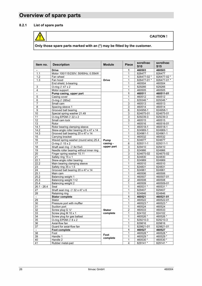
Overview of spare parts 8.2.1 List of spare parts
CAUTION !
Only those spare parts marked with an (*) may be fitted by the customer.
Item no. Description Module Piece scrollvac S10
scrollvac S15
- Drive 1 460503 460503 1.1 Motor 100/115/230V; 50/60Hz; 0.55kW 1 826477 826477 1.2 Fan wheel 1 826477-02 * 826477-02 * 1.3 Fan hood 1 826477-01 * 826477-01 * End shield, b-bearing 1 460504 460504 3 O-ring ∅ 47 x 2 1 829266 829266 4 Motor support
Drive
1 460505 460505 - Pump casing, upper part 1 460511 460511-01 5 Casing cover 1 460512 460512 6 O-ring ∅ 285x2 1 829346 * 829346 * 7 Small cam 3 460513 460513 8 Spacing sleeve 1 3 460514 460514 9 Grooved ball bearing 6 824958-1 824958-1 10 Special spring washer 21.49 3 824675-01 824675-01 11 O-ring EPDM ∅ 22 x 2 3 829239-3 829239-3 12 Small cam lock 3 460515 460515 13 Rotor 1 460516 460516-01 14.1 Rotor bearing clamping sleeve 1 460518-1 460518-1 14.2 Skew-angle roller bearing 20 x 47 x 14 1 824969-1 824969-1 14.3 Grooved ball bearing 20 x 47 x 14 1 824961-1 824961-1 15 Carrying bracket 1 460532 460532 16 Waved spring washer (round wire) 25.4 1 824677 824677 17 O-ring ∅ 15 x 2 6 829311-1 829311-1 18 Shaft seal ring ∅ 8x15x3 3 829410 829410 19 Needle roller bearing without inner ring 3 824966 824966 20 Finger spring washer 15.11 3 824675-02 824675-02 21 Safety ring 15 x 1 3 824830 824830 22.1 Skew-angle roller bearing 1 824969 824969 22.2 Main bearing clamping sleeve 1 460510 460510 23 Safety ring 35 x 1.5 1 824831 824831 24 Grooved ball bearing 20 x 47 x 14 1 824961 824961 25.1 Main cam 1 460506 460506 25.2 Balancing weight 1 1 460507 460507-01 25.3 Balancing weight 1+2 2 460508 460508 25.4 Balancing weight 2 1 460509 460509-01 26.1 - 26.4 Seal 1 460531 * 460531 * 27 Shaft seal ring ∅ 32 x 47 x 6 1 829407 829407 28 Retaining ring
Pump casing - upper part
1 824846 824846 - Stator complete 1 460521 460521-01 29 Stator 1 460522 460522-01 30 Pressure port with muffler 1 460523 * 460523 * 31 Suction port 1 460524 460524 32 Screw plug G ¼“ 2 460533 460533 33 Screw plug M 10 x 1 1 824102 824102 34 Screw plug for gas ballast 1 460526 * 460526 * 35 O-ring EPDM ∅ 8 x 2 1 829210-3 829210-3 36 Axial-flow fan 1 829816 829816 37 Guard for axial-flow fan
Stator complete
1 829821-01 829821-01 - Foot complete 1 460527 460527 38 Foot 1 460528 * 460528 * 39 Handle 1 1 460529 * 460529 * 40 Handle 2 1 460530 * 460530 * 41 Rubber metal-pad
Foot complete
4 829141 * 829141 *
26 Ilmvac GmbH 460004