Embed Size (px)
Citation preview

ScreenMaster User Guide
Ethernet CommunicationsOption
SM1000

ABB
The Company
We are an established world force in the design and manufacture of instrumentation forindustrial process control, flow measurement, gas and liquid analysis and environmentalapplications.
As a part of ABB, a world leader in process automation technology, we offer customersapplication expertise, service and support worldwide.
We are committed to teamwork, high quality manufacturing, advanced technology andunrivalled service and support.
The quality, accuracy and performance of the Company’s products result from over 100 yearsexperience, combined with a continuous program of innovative design and development toincorporate the latest technology.
The NAMAS Calibration Laboratory No. 0255 is just one of the ten flow calibration plantsoperated by the Company, and is indicative of our dedication to qualityand accuracy.
Use of Instructions
Warning.An instruction that draws attention to the risk of injury ordeath.
Caution.An instruction that draws attention to the risk of damage tothe product, process or surroundings.
✶ Note.Clarification of an instruction or additional information.
Information.Further reference for more detailed information ortechnical details.
Although Warning hazards are related to personal injury, and Caution hazards are associated with equipment or property damage,it must be understood that operation of damaged equipment could, under certain operational conditions, result in degradedprocess system performance leading to personal injury or death. Therefore, comply fully with all Warning and Caution notices.
Information in this manual is intended only to assist our customers in the efficient operation of our equipment. Use of this manualfor any other purpose is specifically prohibited and its contents are not to be reproduced in full or part without prior approval of theMarketing Communications Department.
Health and SafetyTo ensure that our products are safe and without risk to health, the following points must be noted:
1. The relevant sections of these instructions must be read carefully before proceeding.
2. Warning labels on containers and packages must be observed.
3. Installation, operation, maintenance and servicing must only be carried out by suitably trained personnel and in accordance with theinformation given.
4. Normal safety precautions must be taken to avoid the possibility of an accident occurring when operating in conditions of high pressureand/or temperature.
5. Chemicals must be stored away from heat, protected from temperature extremes and powders kept dry. Normal safe handling proceduresmust be used.
6. When disposing of chemicals ensure that no two chemicals are mixed.
Safety advice concerning the use of the equipment described in this manual or any relevant hazard data sheets (where applicable) may beobtained from the Company address on the back cover, together with servicing and spares information.
BS EN ISO 9001
Cert. No. Q5907
REGISTERE
D
EN 29001 (ISO 9001)
Lenno, Italy – Cert. No. 9/90A
0255
Stonehouse, U.K.

1
CONTENTS 1 INTRODUCTION
1 INTRODUCTION .............................................................. 11.1 Ethernet Communications ......................................... 11.2 Higher Level Protocols .............................................. 2
2 INSTALLATION ................................................................ 32.1 General ..................................................................... 32.2 One-To-One Connection
between the Recorder and a Computer ..................... 32.3 Connection to a Network Hub................................... 42.4 Connection to a Dial-Up Router ................................ 42.5 Connection to an Internet Gateway ........................... 4
3 CONFIGURATION ............................................................ 53.1 General ..................................................................... 5
4 OPERATION ..................................................................... 64.1 Testing Operation on a Network ................................ 64.2 FTP Access .............................................................. 64.3 Setting Up FTP Access
for use with DataManager .......................................... 64.4 Using FTP Access
with DataManager ..................................................... 84.5 File Transfer Scheduler Program................................ 94.6 ScreenMaster Web Server ........................................ 9
5 GLOSSARY .................................................................... 15
APPENDIX ........................................................................... 16A1 FTP Access via MS-DOS ......................................... 16A2 FTP Access via Internet Explorer ............................. 17
The Ethernet module option enables the Recorder to beconnected to computer networks for remote monitoring anddata access.
1.1 Ethernet CommunicationsEthernet is a form of electronic communication that has beenadopted as a worldwide networking standard. Each device onan Ethernet acts independently from other stations on thenetwork, which has no central controller.
There are a number of media that can be used for Ethernetinterconnections (for example coaxial cable, unshielded twistedpair cables and air transmission). The Ethernet module used inthe Recorder supports a standard called 10BaseT that usesunshielded twisted pair (UTP) cable to connect nodes. UTPcable comprises four pairs of wires twisted together into a singlecable.
Ethernet signals are transmitted serially, one bit at a time, over ashared signal channel to every station attached to the network.When a station has data to transmit, it listens to the channel towait until the channel is idle then transmits its data as anEthernet frame or packet. After each frame transmission allstations must contend equally for the next frame transmissionopportunity. This ensures that no station can lock out the otherstations on the network.
Access to the network channel is determined by the MediumAccess Control (MAC) mechanism embedded in the Ethernetinterface of each station. This mechanism is based on a CarrierSense Multiple Access with Collision Detection (CSMA/CD)system.
Each Ethernet frame contains the source and destinationaddresses for the frame, a variable size data field and an error-checking field that checks the integrity of the frame content toensure that it has been delivered intact. The address fields,called physical or MAC addresses, are each 48-bits long. Everystation on the network has a unique, pre-assigned MAC addressprogrammed into its Ethernet Option board.

2
File Transfer Request
File Information
FTPServer
FTPClient
EmbeddedWeb
Server
Web Enabled Device
HTTPWeb
Browser
Host PC
...1 INTRODUCTION
HTTP enables the transfer of hypertext files such as web pages.It enables a web browser to access pages within a web server:
noitacilppAslocotorP
refsnarTeliF)PTF(locotorP
)PTTH(locotorPrefsnarTtxeTrepyH
leveLwoLkrowteNslocotorP
)PCT(locotorPlortnoCtropsnarT
tenretnI)PI(locotorP
sserddAnoituloseR
)PRA(locotorP
lortnoCtenretnIegasseM
)PMCI(locotorPkniLataD tenrehtElacisyhP
aideMriaPdetsiwT
Table 1.1 Protocol Layers
Fig. 1.1 Typical FTP Transfer
Fig 1.2 Typical HTTP Transfer
1.2 Higher Level ProtocolsData can be transmitted over an Ethernet network using higherlevel protocols that overlay the Ethernet infrastructure. Thehigher level protocol packets are contained within the data fieldof Ethernet packets. The Recorder uses a protocol called TCP/IP (Transmission Control Protocol/Internet Protocol), which is aworldwide standard that has been used to create the Internet.
The Internet Protocol (IP) routes the packets of information totheir destination devices. The routing is performed using an IPaddress embedded in the header attached to each packet. TheIP address is a 32-bit number divided into four sections (calledoctets) that are shown as decimal values. A typical example is192.168.1.1.
The Transmission Control Protocol (TCP) establishes aconnection between the two devices before any data istransmitted. This enables confirmation of reception of alltransmitted packets, so that any lost packets can be re-transmitted.
Other protocols that operate at the same level are the AddressResolution Protocol (ARP) and the Internet Control MessageProtocol (ICMP).
Above the TCP and IP layers there are a number of applicationprotocols that perform a range of tasks. Typical examples areFile Transfer Protocol (FTP) and HyperText Transfer Protocol(HTTP).
These layers fit together to provide a full data transfer system:
FTP provides a reliable mechanism for the transfer of filesbetween a client and a server:
3
SM1000/2000
PC
CrossoverCable
Link/Receive LED
Transmit LED
RJ45 Connector(Type 5)
TD+
TD–
RD+
RD–
TD+
TD–
RD+
RD–
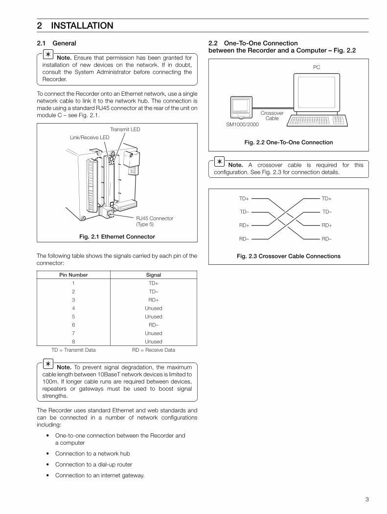
2.1 General
Note. Ensure that permission has been granted forinstallation of new devices on the network. If in doubt,consult the System Administrator before connecting theRecorder.
To connect the Recorder onto an Ethernet network, use a singlenetwork cable to link it to the network hub. The connection ismade using a standard RJ45 connector at the rear of the unit onmodule C – see Fig. 2.1.
Fig. 2.2 One-To-One Connection
Fig. 2.3 Crossover Cable Connections
Fig. 2.1 Ethernet Connector
2.2 One-To-One Connectionbetween the Recorder and a Computer – Fig. 2.2
Note. A crossover cable is required for thisconfiguration. See Fig. 2.3 for connection details.
2 INSTALLATION
rebmuNniP langiS
1 +DT
2 –DT
3 +DR
4 desunU
5 desunU
6 –DR
7 desunU
8 desunU
ataDtimsnarT=DT ataDevieceR=DR
The following table shows the signals carried by each pin of theconnector:
Note. To prevent signal degradation, the maximumcable length between 10BaseT network devices is limited to100m. If longer cable runs are required between devices,repeaters or gateways must be used to boost signalstrengths.
The Recorder uses standard Ethernet and web standards andcan be connected in a number of network configurationsincluding:
• One-to-one connection between the Recorder anda computer
• Connection to a network hub
• Connection to a dial-up router
• Connection to an internet gateway.

4
SM1000/SM2000 SM1000/SM2000
Hub
PC PC
SM1000/SM2000
PC PC
SM1000/SM2000
WAN / InternetRouter Router
SM1000/SM2000
PC PC
SM1000/SM2000
Internet Gateway
...2 INSTALLATION
Fig. 2.4 Connection to a Network Hub
Fig. 2.5 Connection to a Dial-Up Router
Fig. 2.6 Connection to an Internet Gateway
2.4 Connection to a Dial-Up Router – Fig. 2.5
2.3 Connection to a Network Hub – Fig. 2.4
2.5 Connection to an Internet Gateway – Fig. 2.6

5
A:- Analog i/p C:- Ethernet
IP-address 192.168.1.1
Subnet mask 255.255.255.0
Default gateway 0.0.0.0
FTP User 1 Operator 1:PASS
���������
��������� �����
�
� ��������� ����
�������� ������
Set the IP address for the 'Default gateway' (router, switch etc.)required to communicate with other networks. This setting maynot be required. The default setting is '0.0.0.0'
The 'FTP User' name and password are used during logon toenable the FTP server. Access for up to four different users isprovided. These passwords can also be used to allow access tosome functionality provided by the web server.
Enter the name of user required for FTP login.
Enter the password required for FTP login.
Select whether this FTP user has full access (i.e. the ability toread, write and delete files) or read-only access.
Note. If a user is given full access via FTP, that user isable to delete both data and configuration files. This couldresult in erroneous operation of the Recorder.
3 CONFIGURATION
3.1 General
Note. Changes to the IP address, subnet mask anddefault gateway are implemented only after the Recorderhas been restarted. Change the addressing parameters,exit and save the configuration, wait until the 'Please Wait'message disappears then power down and restart theRecorder.
SM1000 only – from the 'System Configuration' screen, accessthe Ethernet Module:
SM2000 only – from the 'System Configuration' screen, accessthe Ethernet Module:
Set the 'IP-address' to be assigned to the Recorder. The IPaddress is used by the TCP/IP protocol to distinguish betweendifferent sources. The address is a 32-bit value expressed withfour values (0 to 255), each separated by a period (.).
The 'Subnet-mask' is used to indicate which part of the IPaddress is for the network ID and which is for the host ID. Set as'1's each bit which is part of the network ID, e.g. 255.255.255.0indicates first 24 bits are for the Network ID.
Common
Group 1
Channels 1.1 - 1.6
Group 2
Channels 2.1 - 2.6
Functions
I/O Modules
Exit
A:- Analog i/p C:- Ethernet
Subnet mask
FTP User 1
IP-address
Default gateway
Operator 1:PASS
0.0.0.0
255.255.255.0
192.168.1.1
I/O Modules
�������������������
��� ���������
��������������
��� ����������
���������������
!"������
#�� �����
���� ��������������
!"������
������������������������
�$%���������!� �$%�&�������
'�(�������)
#*�������
�%�������
+�������������,
��������$��''
-.-.-.-
�//.�//.�//.-
0�.12..
6
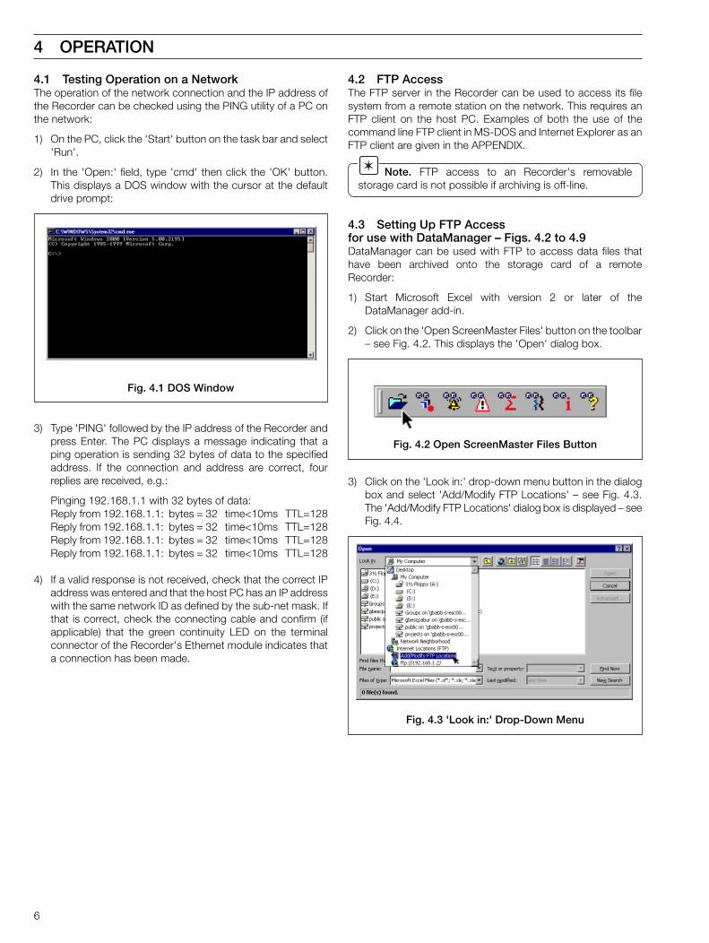
4.1 Testing Operation on a NetworkThe operation of the network connection and the IP address ofthe Recorder can be checked using the PING utility of a PC onthe network:
1) On the PC, click the 'Start' button on the task bar and select'Run'.
2) In the 'Open:' field, type 'cmd' then click the 'OK' button.This displays a DOS window with the cursor at the defaultdrive prompt:
3) Type 'PING' followed by the IP address of the Recorder andpress Enter. The PC displays a message indicating that aping operation is sending 32 bytes of data to the specifiedaddress. If the connection and address are correct, fourreplies are received, e.g.:
Pinging 192.168.1.1 with 32 bytes of data:Reply from 192.168.1.1: bytes = 32 time<10ms TTL=128Reply from 192.168.1.1: bytes = 32 time<10ms TTL=128Reply from 192.168.1.1: bytes = 32 time<10ms TTL=128Reply from 192.168.1.1: bytes = 32 time<10ms TTL=128
4) If a valid response is not received, check that the correct IPaddress was entered and that the host PC has an IP addresswith the same network ID as defined by the sub-net mask. Ifthat is correct, check the connecting cable and confirm (ifapplicable) that the green continuity LED on the terminalconnector of the Recorder's Ethernet module indicates thata connection has been made.
4.2 FTP AccessThe FTP server in the Recorder can be used to access its filesystem from a remote station on the network. This requires anFTP client on the host PC. Examples of both the use of thecommand line FTP client in MS-DOS and Internet Explorer as anFTP client are given in the APPENDIX.
Note. FTP access to an Recorder's removablestorage card is not possible if archiving is off-line.
4.3 Setting Up FTP Accessfor use with DataManager – Figs. 4.2 to 4.9DataManager can be used with FTP to access data files thathave been archived onto the storage card of a remoteRecorder:
1) Start Microsoft Excel with version 2 or later of theDataManager add-in.
2) Click on the 'Open ScreenMaster Files' button on the toolbar– see Fig. 4.2. This displays the 'Open' dialog box.
3) Click on the 'Look in:' drop-down menu button in the dialogbox and select 'Add/Modify FTP Locations' – see Fig. 4.3.The 'Add/Modify FTP Locations' dialog box is displayed – seeFig. 4.4.
4 OPERATION
Fig. 4.1 DOS Window
Fig. 4.2 Open ScreenMaster Files Button
Fig. 4.3 'Look in:' Drop-Down Menu

7
…4.3 Setting Up FTP Accessfor use with DataManager – Figs. 4.2 to 4.9
4 OPERATION...
Fig. 4.4 Add/Modify FTP Locations Dialog BoxFig. 4.5 Entering the User Name and Password
5) In the 'Name of FTP site' field enter the IP address of theRecorder to be accessed by DataManager.
6) In the 'Log on as:' area select the 'User' radio button.
7) Enter the 'User' name and 'Password:' for the remoteRecorder (see User Guide), then click on the 'Add' button –see Fig. 4.5.

8
6) Click on the 'Storage_Card' folder and click on the 'Open'button. All the subfolders for the storage card are displayed.
7) Select the data file to be accessed by DataManager and clickon the 'Open' button – see Fig. 4.9. The file is opened anddisplayed within DataManager.
...4 OPERATION
Fig. 4.6 'Look in' Drop-Down Menu
Fig. 4.7 FTP Log on Dialog
Fig. 4.8 Typical Folders
Fig. 4.9 Typical Files
…4.3 Setting Up FTP Accesswith DataManager – Figs. 4.2 to 4.68) Click on the 'OK' button to close the 'Add/Modify FTP
Locations' dialog box and return to the 'Open' dialog box –see Fig. 4.6.
4) In the 'Log on as:' area select the 'User' radio button.
5) Enter the 'User' name and 'Password:' for the remoteRecorder (see User Guide), then click the 'OK' button. A setof folder icons are displayed – see Fig. 4.8.
9) Repeat steps 3) to 9) to add more Recorders as required.
4.4 Using FTP Accesswith DataManager – Figs. 4.7 to 4.91) Start Microsoft Excel with version 2 or later of the
DataManager add-in.
2) Click on the 'Open Screenmaster Files' button on the toolbar– see Fig. 4.2. This displays the 'Open' dialog box.
3) Open the 'Look in:' drop-down menu and select the FTPaddress of the remote Recorder. The 'FTP Log On' dialogbox is displayed – see Fig. 4.7.
Note. To ensure that the latest data file is copied, thebrowser must be set to check for newer versions of storedpages on every visit to a page. If this check is not performed,the browser may use data stored in the cache of the localPC rather than retrieving current data over the network fromthe remote device. (See APPENDIX for details if usingMicrosoft Internet Explorer).

9
IP addressof Recorder
Recorder tag
'Show CompleteLog'hyperlinkshown if oneof the log views isdisplayed.Clicking on thiscauses theentire log to bedisplayed in thebrowser window
Current displayon Recorder'sscreen
Note. This isinhibited if theRecorder is inhistorical reviewor ConfigurationMode
Drop-down selection box ofviews available.The Recorder's displaychanges to the view selected
Note. The screen image maytake a number of seconds toupdate
If enabled, the screen imageis updated every 10 seconds
Languageselection forweb pages
Menu buttonsto display current
Recorder dataand states
4 OPERATION...
4.5 File Transfer Scheduler ProgramAn FTP scheduler program enables archive and configurationfiles to be transferred automatically to a PC using FTP. Thetransferred files can be stored either on the local drive of the PCor on a network drive for easy access and secure back-up.
To obtain the File Transfer Scheduler Program (FTSP), send ane-mail to [email protected] with 'download' in theemail subject line.
Fig. 4.10 Home Page
4.6 ScreenMaster Web Server – Figs 4.10 to 4.19Each Recorder fitted with the Ethernet Communications Modulecontains an embedded web server. This means that theRecorder's data and status can be viewed remotely using anInternet browser on a PC – see Figs. 4.10 to 4.18 for examplesof the page views available. The web server supports up to eightindependent connections. To connect the browser on the PC tothe ScreenMaster Web Server, type the IP address of theRecorder (for example: http://192.168.1.1) into the browser'Address' field and press Enter.

10
Primary andsecondarysample ratesset inConfiguration
Current statusof recording
Alarm status ofeach channel –refer to UserGuide foridentificationof alarm icons
Channel tags
Enabled recordingchannels
(the color codingis the same as
the standard tracecolors used onthe Recorder)
Latest value ofchannel and
units ofmeasure
Auto refresh.If enabled, the
values areupdated
automaticallyevery 10 seconds
Alarm type
Configuredalarms,
color codedfor eachchannel
Alarm tag
Alarm tripvalue and
units ofmeasure
Current alarmstatus
...4 OPERATION
Fig. 4.11 Recording Channels Page
Fig. 4.12 Alarms Page
…4.6 ScreenMaster Web Server – Figs 4.10 to 4.19

11
Totalizer tag
Configured totalizers,color coded for each
channel
Current batch total
Current secure total
Totalizer units ofmeasure
Totalizer presetandpredeterminedvalues
Current totalizerstatus
Time remaining beforeremovable media card
is full (assumingarchiving continues at
current rate)
% memory used onremovable media card
Confirmation of achivingstatus
Filename tags used forarchive data files
Removable media status(Online, Offline or
Not Present)
4 OPERATION...
Fig. 4.13 Totalizers Page
Fig. 4.14 Archiving Page
…4.6 ScreenMaster Web Server – Figs 4.10 to 4.19

12
List of all digitalsignals availableon the Recorder
Current status ofdigital signals
Module Aanalog I/Ps
Cold junctioncompensation
reading formodule A
Module Banalog I/Ps
Cold junctioncompensation
reading formodule B
Fig. 4.15 Analog Signals Page
Fig. 4.16 Digital Signals Page
...4 OPERATION
…4.6 ScreenMaster Web Server – Figs 4.10 to 4.19

13
Hardwarefitted
Software revisionand options
Recorder identification
Enter an associated FTPpassword
Enter a valid FTP username –see Configuration
Enter message to be sentto the Recorder
(max. 20 characters)
Click on button to sendmessage.
The message is storedin the Recorder's alarm
event log and if enabled itis displayed in the
chart view
Fig. 4.17 Operator Message Page
Fig. 4.18 ScreenMaster Service Information Page
4 OPERATION...
…4.6 ScreenMaster Web Server – Figs 4.10 to 4.19
14
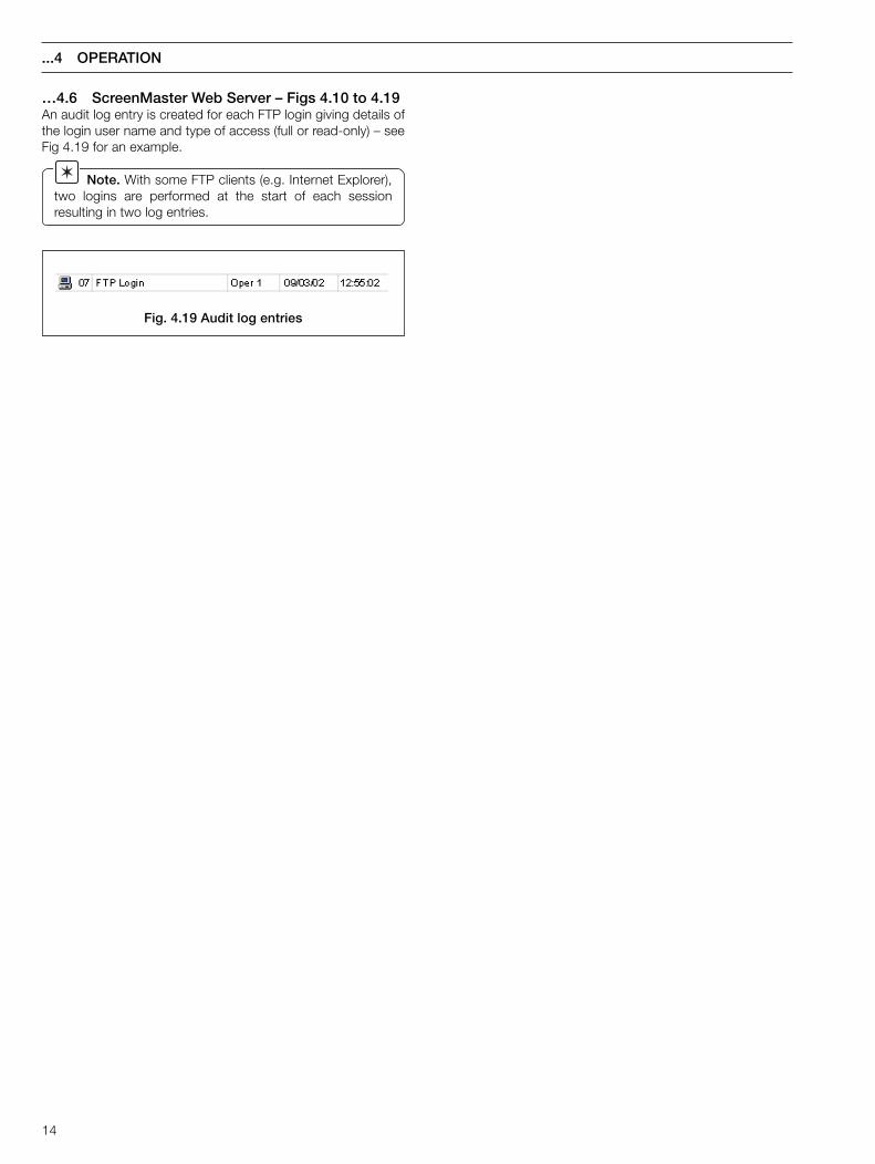
Fig. 4.19 Audit log entries
...4 OPERATION
…4.6 ScreenMaster Web Server – Figs 4.10 to 4.19An audit log entry is created for each FTP login giving details ofthe login user name and type of access (full or read-only) – seeFig 4.19 for an example.
Note. With some FTP clients (e.g. Internet Explorer),two logins are performed at the start of each sessionresulting in two log entries.

15
5 GLOSSARY
The following terms have specific meanings within the Ethernetenvironment:
10BaseTA definition of the cable type and transmission rate of thenetwork. The '10' represents a transmission rate of 10Mbpsand the 'T' for Unshielded twisted pair cable.
100BaseTA higher speed version of 10BaseT with a transmission rateof 100Mbps.
ARPAddress Resolution Protocol. Converts between IPaddresses and MAC (hardware) addresses on the network.
Default gatewayThe IP address of the gateway (router, switch etc) that isused to communicate with other networks.
FTPFile Transfer Protocol. A TCP/IP suite application thatprovides an efficient and reliable means of transferring filesbetween a remote server and a client.
HTTPHyperText Transfer Protocol. Used for the transfer of webpages.
ICMPInternet Control Message Protocol. An Internet protocol sentin response to errors in TCP/IP messages. It is an errorreporting protocol between a host and a gateway.
IP addressInternet Protocol address. This is the unique address givento each computer on a TCP/IP network (including theInternet).
MAC addressMedia Access Control address, also called the hardware orphysical address. This is a unique address given to eachEthernet interface that is used in an Ethernet packet toidentify the source and destination of the data being sent.
Open systemA system that conforms to specifications and guidelineswhich are 'open' to all. This allows equipment from anymanufacturer, which comply with these standards, to beused interchangeably on the standard network.
RouterLinks a local network to a remote network. For example, yourcompany's network probably uses a router to connect to theInternet. Can be used to connect a LAN to a LAN, a WAN toa WAN, or a LAN to the Internet.
Sub-net mask (or Sub-Network Mask)A mask used to determine what subnet an IP addressbelongs to (an IP address has two components, the networkaddress and the host address).
TCP/IPTransmission Control Protocol/Internet Protocol. Thelanguage all computers on the Internet (and in most smalloffices) use to communicate with each other.
UTPUnshielded Twisted Pair. The type of wire that is used in10BaseT Ethernet communications.
16
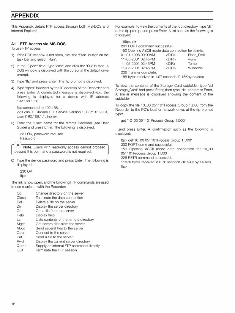
This Appendix details FTP access through both MS-DOS andInternet Explorer.
A1 FTP Access via MS-DOSTo use FTP access:
1) If the DOS window is not open, click the 'Start' button on thetask bar and select 'Run'.
2) In the 'Open:' field, type 'cmd' and click the 'OK' button. ADOS window is displayed with the cursor at the default driveprompt.
3) Type 'ftp' and press Enter. The ftp prompt is displayed.
4) Type 'open' followed by the IP address of the Recorder andpress Enter. A connected message is displayed (e.g. thefollowing is displayed for a device with IP address192.168.1.1):
ftp>connected to 192.168.1.1220 WinCE GkWare FTP Service (Version 1.3 Oct 15 2001)User (192.168.1.1: (none):
5) Enter the 'User' name for the remote Recorder (see UserGuide) and press Enter. The following is displayed:
331 OK, password requiredPassword:
Note. Users with read-only access cannot proceedbeyond this point and a password is not required.
6) Type the device password and press Enter. The following isdisplayed:
230 OKftp>
The link is now open, and the following FTP commands are usedto communicate with the Recorder:
Cd Change directory on the serverClose Terminate the data connectionDel Delete a file on the serverDir Display the server directoryGet Get a file from the serverHelp Display helpLs Lists contents of the remote directoryMget Get several files from the serverMput Send several files to the serverOpen Connect to the serverPut Send a file to the serverPwd Display the current server directoryQuote Supply an internal FTP command directlyQuit Terminate the FTP session
For example, to view the contents of the root directory, type 'dir'at the ftp prompt and press Enter. A list such as the following isdisplayed:
16ftp> dir200 PORT command successful.150 Opening ASCII mode data connection for /bin/ls.01-01-1998 00:00AM <DIR> Flash_Disk11-05-2001 02:45PM <DIR> www11-05-2001 02:45PM <DIR> Temp11-05-2001 02:45PM <DIR> Windows226 Transfer complete.188 bytes received in 1.07 seconds (0.18Kbytes/sec)
To view the contents of the Storage_Card subfolder, type 'cdStorage_Card' and press Enter, then type 'dir' and press Enter.A similar message is displayed showing the content of thesubfolder.
To copy the file 10_00 051101Process Group 1.D00 from theRecorder to the PC's local or network drive, at the ftp prompttype:
get '10_00 051101Process Group 1.D00'
…and press Enter. A confirmation such as the following isdisplayed:
ftp> get'10_00 051101Process Group 1.D00'200 PORT command successful.150 Opening ASCII mode data connection for 10_00051101Process Group 1.D00226 RETR command successful.11876 bytes received in 0.70 seconds (16.94 Kbytes/sec)ftp>
APPENDIX
17
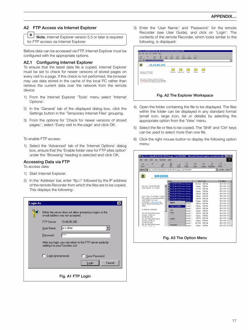
A2 FTP Access via Internet Explorer
Note. Internet Explorer version 5.5 or later is requiredfor FTP access via Internet Explorer.
Before data can be accessed via FTP, Internet Explorer must beconfigured with the appropriate options.
A2.1 Configuring Internet ExplorerTo ensure that the latest data file is copied, Internet Explorermust be set to check for newer versions of stored pages onevery visit to a page. If this check is not performed, the browsermay use data stored in the cache of the local PC rather thanretrieve the current data over the network from the remotedevice.
1) From the Internet Explorer 'Tools' menu select 'InternetOptions'.
2) In the 'General' tab of the displayed dialog box, click theSettings button in the 'Temporary Internet Files' grouping.
3) From the options for 'Check for newer versions of storedpages:', select 'Every visit to the page' and click OK.
To enable FTP access:
1) Select the 'Advanced' tab of the 'Internet Options' dialogbox, ensure that the 'Enable folder view for FTP sites option'under the 'Browsing' heading is selected and click OK.
Accessing Data via FTPTo access data:
1) Start Internet Explorer.
2) In the 'Address' bar, enter 'ftp://' followed by the IP addressof the remote Recorder from which the files are to be copied.This displays the following:
Fig. A1 FTP Login
Fig. A2 The Explorer Workspace
3) Enter the 'User Name:' and 'Password:' for the remoteRecorder (see User Guide), and click on 'Login'. Thecontents of the remote Recorder, which looks similar to thefollowing, is displayed:
APPENDIX…
4) Open the folder containing the file to be displayed. The fileswithin the folder can be displayed in any standard format(small icon, large icon, list or details) by selecting theappropriate option from the 'View' menu.
5) Select the file or files to be copied. The 'Shift' and 'Ctrl' keyscan be used to select more than one file.
6) Click the right mouse button to display the following optionmenu:
Fig. A3 The Option Menu

18
…A2 FTP Access via Internet Explorer7) Select the 'Copy To Folder' option. The 'Browse for Folder'
dialog box is displayed:
APPENDIX
Fig. A4 The Browse Window
8) Select the drive and folder to which the file is to be copied.
9) Click on OK. The file is copied into the selected folder.

19
NOTES

20
…NOTES
Netscape Navigator is a registered trademark of Netscape Communications Corporation
Internet Exporer, Dos and Windows are registed trademarks of Microsoft Corporation

PRODUCTS & CUSTOMER SUPPORT
ProductsAutomation Systems
• for the following industries:– Chemical & Pharmaceutical– Food & Beverage– Manufacturing– Metals and Minerals– Oil, Gas & Petrochemical– Pulp and Paper
Drives and Motors• AC and DC Drives, AC and DC Machines, AC motors to 1kV• Drive systems• Force Measurement• Servo Drives
Controllers & Recorders• Single and Multi-loop Controllers• Circular Chart , Strip Chart and Paperless Recorders• Paperless Recorders• Process Indicators
Flexible Automation• Industrial Robots and Robot Systems
Flow Measurement• Electromagnetic Magnetic Flowmeters• Mass Flow Meters• Turbine Flowmeters• Wedge Flow Elements
Marine Systems & Turbochargers• Electrical Systems• Marine Equipment• Offshore Retrofit and Referbishment
Process Analytics• Process Gas Analysis• Systems Integration
Transmitters• Pressure• Temperature• Level• Interface Modules
Valves, Actuators and Positioners• Control Valves• Actuators• Positioners
Water, Gas & Industrial Analytics Instrumentation• pH, conductivity, and dissolved oxygen transmitters and
sensors• ammonia, nitrate, phosphate, silica, sodium, chloride,
fluoride, dissolved oxygen and hydrazine analyzers.• Zirconia oxygen analyzers, katharometers, hydrogen purity
and purge-gas monitors, thermal conductivity.
Customer Support
We provide a comprehensive after sales service via aWorldwide Service Organization. Contact one of the followingoffices for details on your nearest Service and Repair Centre.
United KingdomABB LimitedTel: +44 (0)1480 475 321Fax: +44 (0)1480 217 948
United States of AmericaABB Inc.Tel: +1 215 674 6000Fax: +1 215 674 7183
Client Warranty
Prior to installation, the equipment referred to in this manualmust be stored in a clean, dry environment, in accordance withthe Company's published specification. Periodic checks must bemade on the equipment's condition.
In the event of a failure under warranty, the followingdocumentation must be provided as substantiation:
1. A listing evidencing process operation and alarm logs at timeof failure.
2. Copies of operating and maintenance records relating to thealleged faulty unit.

IM/S
ME
NE
TIs
sue
1
The Company’s'policy is one of continuous productimprovement and the right is reserved to modify the
information contained herein without notice.
Printed in UK (05.02)
© ABB 2002
ABB LimitedHoward Road, St. NeotsCambridgeshire, PE19 8EUUK
Tel: +44 (0)1480 475 321Fax: +44 (0)1480 217 948
ABB Inc.125 E. County Line RoadWarminster, PA 18974USA
Tel: +1 215 674 6000Fax: +1 215 674 7183
ABB has Sales & Customer Supportexpertise in over 100 countries worldwide
www.abb.com