Embed Size (px)
Citation preview
SCOREBOARD HOCKEY MANUAL FOR
Installation Operation Service
U1000
Kodiak Industries Ltd. Scoretec Division 1865 Burrows Ave
Winnipeg, MB CANADA R2X 2V9 Phone (204) 224.3221 Fax (204) 224.1577
OPERATION MANAUL FOR HOCKEY SCOREBOARDS TABLE OF CONTENTS
INSTALLATION
PAGE 1-3
OPERATION PAGE 4
GENERAL DESCRIPTION PAGE 4
WARRANTY PAGE 5
THE CONTROL CONSOLE PAGE 6
CONTROL ENTRY PROCEDURES PAGE 7
“TIME OF DAY” ENTRY PAGE 8
“RUNNING TIME” ENTRY, DOWNCOUNT MODE PAGE 9
“RUNNING TIME: ENTRY, UPCOUNT MODE PAGE 9
“INTERMISSION TIME” ENTRY PAGE 10
“ELAPSED TIME” PAGE 10
“INTERVAL HORN” ENTRY, DOWNCOUNT MODE PAGE 11
“INTERVAL HORN” ENTRY, UPCOUNT MODE PAGE 12
CHECKING INTERVAL ENTRY DATA PAGE 13
“SCORE” ENTRY PAGE 13
“PERIOD” ENTRY PAGE 14
“TIME OUT” PAGE 14
“SHOTS ON GOAL” ENTRY PAGE 15
“PENALTY” ENTRY PAGE 15-16
“PLAYER NUMBER” ENTRY PAGE 17
“STOP-GO PENALTY” ENTRY PAGE 17
“DATA CLEARING” PAGE 18
“TIME INDICATION” PAGE 18
“TIME UP/DOWN”
HOW TO REMOVE PRINTED CIRCUIT BOARD
PAGE 18
PAGE 19
SERVICE INFORMATION PAGE 20
INSTALLATION
Installation of your Scoretec Scoreboard is extremely simple, and requires no special skills or tools. Just follow the step-by step procedures as outlined below.
1. VERIFY ALL PARTS
Before installing the scoreboard, check to see that you have everything as follows: A. Scoreboard B. Control Console C. Control Cable with Connectors D. Separate Horn for Hockey Boards, Model 770 and Up
2. CHECK SCOREBOARD OPERATION
- We recommend that the scoreboard be checked out on the floor prior to installation.
- Plug the control extension cable into the top of the scoreboard and the control console into the junction box of the extension cable.
- Plug the scoreboard power cord into a 110 VAC outlet. This must be three wire grounded outlet.
- Some of the larger boards are supplied with a disconnect switch on top of the scoreboard (as per C.S.A. regulations). These boards do not have a power cord as they must be direct wired, however a temporary hookup can be made in order to check the board.
- Check all functions as outlined in the operation manual.
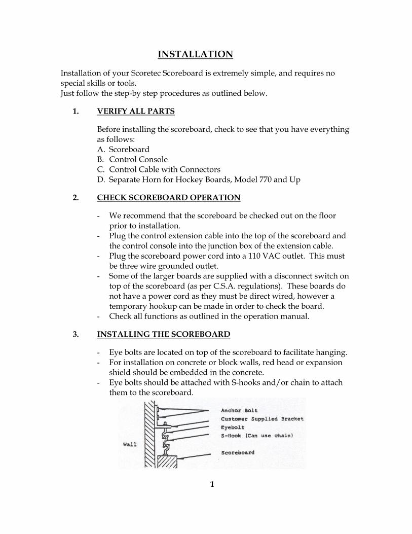
3. INSTALLING THE SCOREBOARD
- Eye bolts are located on top of the scoreboard to facilitate hanging. - For installation on concrete or block walls, red head or expansion
shield should be embedded in the concrete. - Eye bolts should be attached with S-hooks and/or chain to attach
them to the scoreboard.
1
4. ELECTRICAL SERVICE
- A 110 VAC 60 HZ grounded electrical outlet must be provided at the scoreboard.
- Some of the larger boards are supplied with a disconnect switch on top of the scoreboard (as per C.S.A. regulations), and must be direct wired.
- A separate circuit should be used to minimize the possibility of electrical noise affecting the scoreboard.
- This line must be switched, either at the breaker box, or with a customer provided wall or key-switch, to turn on or off.
- Separate electrical service is not required at the control-console location.
5. CONTROL EXTENSION CABLE INSTALLATION
- The control extension cable supplied with your scoreboard has been pre wired and checked at the factory.
- The junction box with control-cable receptacle is mounted near the scoring table or wherever the control is to be operated.
- The other end of the control cable plugs into the scoreboard. - This cable carries a maximum of 14 volts, and therefore is not
required to be run in conduit unless your local electrical code requires it.
- We recommend conduit to be used to protect the cable from physical damage at those points where there is easy access to the cable.
END OF INSTALLATION SECTION
2
IMPORTANT NOTE
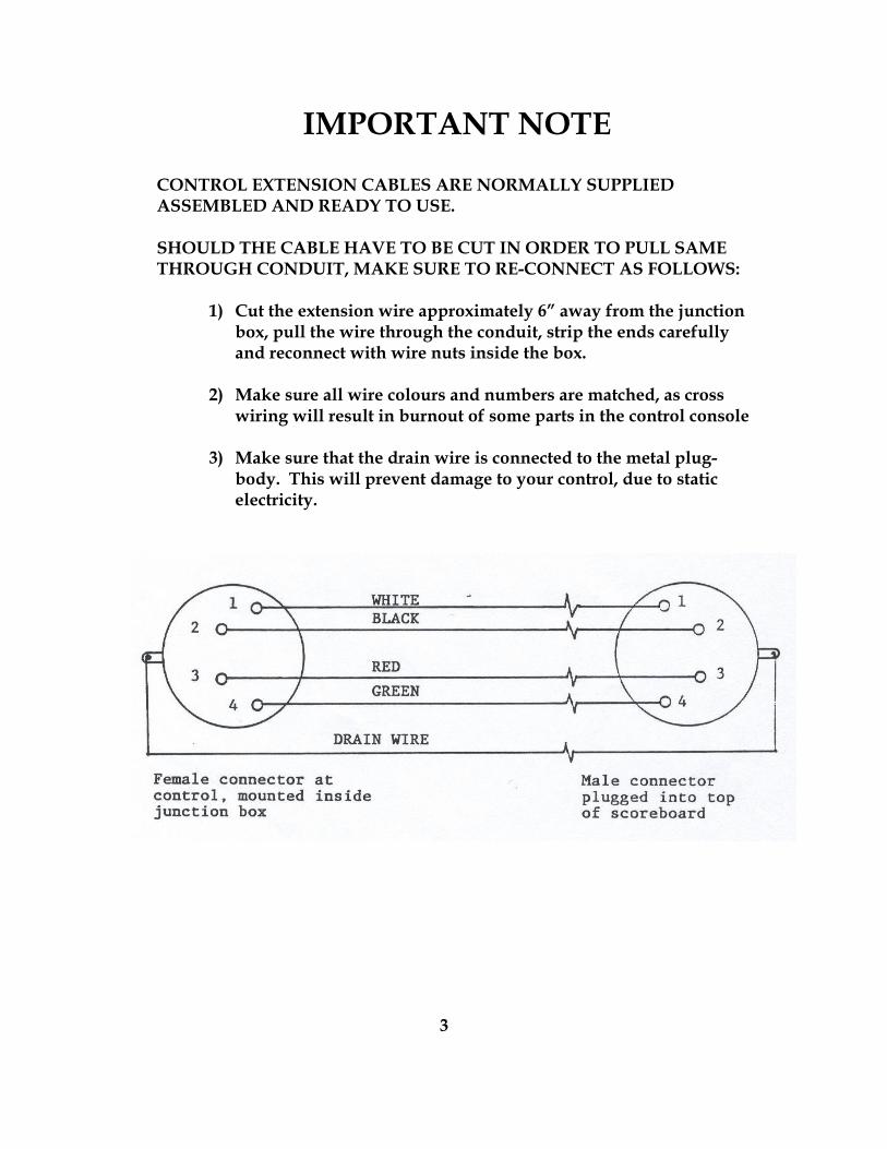
CONTROL EXTENSION CABLES ARE NORMALLY SUPPLIED ASSEMBLED AND READY TO USE. SHOULD THE CABLE HAVE TO BE CUT IN ORDER TO PULL SAME THROUGH CONDUIT, MAKE SURE TO RE-CONNECT AS FOLLOWS:
1) Cut the extension wire approximately 6” away from the junction box, pull the wire through the conduit, strip the ends carefully and reconnect with wire nuts inside the box.
2) Make sure all wire colours and numbers are matched, as cross
wiring will result in burnout of some parts in the control console
3) Make sure that the drain wire is connected to the metal plug-body. This will prevent damage to your control, due to static electricity.
3
OPERATION
You have been supplied with a control console that will run any hockey scoreboard from our smallest 300H model to the largest 782 SOG scoreboard. All of the game information will show up on the liquid crystal display on the control, however, some of the information will not show up on the scoreboard, depending on the model you have purchased.
GENERAL DESCRIPTION OF THE SCOREBOARD SYSTEM
COMPONENTS:
1. PANEL CONTROLLER This is the main printed circuit board located in the scoreboard. It receives all commands from the microprocessor in the control, located at the timekeeper position.
2. PANEL EXTENDER This is a secondary printed circuit board, which is basically only a driver board, receiving orders from the panel controller as described under item 1.
3. THE CONTROL Located at the time-keepers position, it contains the microprocessor section and is the heart of the whole scoreboard system. It controls all functions on the scoreboard, and must be treated with a lot of respect, as it houses some of the most expensive parts in your scoreboard system.
4. THE OPERATION MANUAL All scoreboard functions are described on the following pages, and after practicing a few times, the operation of the system will become as easy as operating a calculator.
5. THE WARRANTY The five (5) year warranty is described on the next page. Familiarize yourself with the terms and conditions, and eliminate voiding your warranty.
4
FIVE (5) YEAR WARRANTY
Scoretec scoreboards carry a limited warranty for a period of five (5) years from the date of invoice against defects in workmanship or materials, and will be repaired at no cost to the owner, provided the equipment or parts are returned on a prepaid basis to Kodiak Industries Ltd. Equipment or parts will be shipped back to the owner on a prepaid basis. Fuses are not included in the warranty. Travel time or time used to remove or reinstall parts, are not included in the warranty. Warranty shall be void, if repairs or alterations other than unplugging printed circuit boards are performed without Kodiak’s authorization, or if the equipment is connected to an incorrect power supply. Incorrect installation of the control-wire can result in damage to the control circuit board and it will not be covered under warranty. For correct installation, see page 2 of this manual. Equipment, which is subjected to neglect or abuse, misuse or natural disasters, is not covered by this warranty. Note: Because of the special nature of this product and the extensive amount of test equipment involved, Kodiak Industries does not authorize any warranty work done by outside firms. It is very much in your interest to have the work done by technicians familiar with your equipment, using the originally specified parts. Standard turn around time on warranty work is 24 hours plus shipping time.
5
THE CONTROL CONSOLE
The control console is the heart of the scoreboard system. It provides all the same information displayed on your scoreboard. Control consoles are differentiated by overlays, which describe and cover the key switches and describe the display fields. The overlays are installed at the factory and are not changeable by the user. All controls are equipped with a 2 X 24 character alphanumeric display. This display provides time, score and status information. The controls have a battery backed-up memory. This memory is maintained by a battery built into the solid-state real time chip. According to the manufacturer, the batteries in the module are specified to keep the memory operating for 10 years. On initial start-up, the “TIME OF DAY” is set to 12:00 and flashes on the control display, asking to be updated (see “time of day” section in the manual.) A PIEZO BEEPER has been installed to provide audible feedback on the key-presses. Three different beepers are made, depending upon the result of the button press. “A” NUMBER BEEP: Short duration, High pitch “B” FUNCTION BEEP: Short duration, Medium pitch “C” ERROR BEEP: Long duration, Low pitch Error beeps will be accompanied by a message explaining the error made. The message will show on the control display.
6
CONTROL ENTRY PROCEDURES
In general, in the following procedures, pressing a function key by itself increments or decrements the corresponding field by 1. To set a field to some specific number, use the following key-sequence:
1) Press “ENTER” key 2) Press “DIGIT” key as required 3) Press function key
To increment the field by some number, use the following key-sequence:
1) Press “PLUS” key 2) Press “DIGIT” key as required 3) Press function key
To decrement the field by some number, use the following key-sequence:
1) Press “MINUS” key 2) Press “DIGIT” key as required 3) Press function key
The digit keys are all those on the digit part of the control console. They include the keys from 0-9, the “/” key, and the “:” key.
The digits are displayed in the staging area as they are pressed. Digits are prompted by a flashing block [] character in the leftmost character of the staging area. New digits appear at the flashing block and the flashing block moves one character to the right. If a + or – key is pressed before the digits, a + or – appears as the rightmost character in the staging area.
When the maximum number of digits is entered, the flashing [] no longer appears to prompt for a new key. Instead, all the entered digits flash. This indicates that no more digits may be entered. Only the “CLEAR” key or a valid function key may be pressed. Any other key causes the “INVALID KEY” error message to appear.
In the event that setting, adding to, or subtracting from a field caused it to grow too large or too small, the operation will terminate and the “TOO LARGE” or “TOO SMALL” error message flashes on the first line of the display. After a few seconds, if no further key is pressed, the display returns to showing the game status.
If an invalid key is pressed at any time in one of these operations or while the display is simply showing the status, then the message “INVALID KEY” or a more descriptive message flashes on the first line of the control display. This message alternates with the normal status display on that line. After a few seconds, if no further key is pressed, the display returns to showing the status. At any time, the “CLEAR” key may be pressed. This key cancels any digits entered in the staging area and returns the console display to simply showing game status.
7
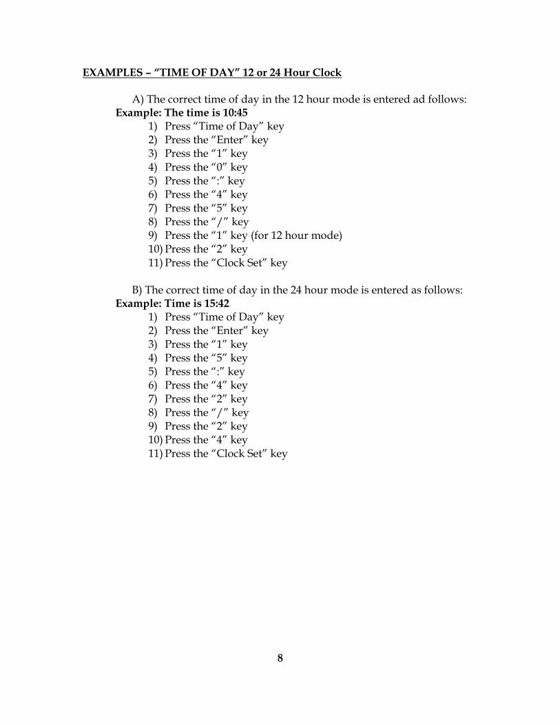
EXAMPLES – “TIME OF DAY” 12 or 24 Hour Clock
A) The correct time of day in the 12 hour mode is entered ad follows: Example: The time is 10:45
1) Press “Time of Day” key 2) Press the “Enter” key 3) Press the “1” key 4) Press the “0” key 5) Press the “:” key 6) Press the “4” key 7) Press the “5” key 8) Press the “/” key 9) Press the “1” key (for 12 hour mode) 10) Press the “2” key 11) Press the “Clock Set” key
B) The correct time of day in the 24 hour mode is entered as follows:
Example: Time is 15:42 1) Press “Time of Day” key 2) Press the “Enter” key 3) Press the “1” key 4) Press the “5” key 5) Press the “:” key 6) Press the “4” key 7) Press the “2” key 8) Press the “/” key 9) Press the “2” key 10) Press the “4” key 11) Press the “Clock Set” key
8
“RUNNING TIME” DOWN-COUNT MODE
You can enter any time span from one second to 99 minutes 59 seconds.
Example #1: You want to enter a 20:00 minute period. You do not have to enter the : or the 00 seconds.
1) Press the “Game Mode” key (Only if scoreboard is showing “Time of Day”). 2) Press the “Enter” key 3) Press the “2” key 4) Press the “0” key 5) Press the “Clock Set” key
Example #2: You want to enter a 19:36 minute period.
1) Press the “Enter” key 2) Press the “1” key 3) Press the “9” key 4) Press the “:” key 5) Press the “3” key 6) Press the ”6” key 7) Press the “Clock Set” key
Note: The scoreboard must always be in the “STOP” mode, when entering or correcting time.
“RUNNING TIME” UPCOUNT MODE
“Up count” running time is used mostly in European Countries
Example: You want to start timing at :00 and count up to 20 minutes. When entering whole minutes, you do not have to enter the : or the 00 seconds.
1) Press the “Game Mode” key 2) Press the “Time Up/Down” key The colon on the display will now show ^^ 3) Press the “Interval Horn” key The insert “Display” is now prompting for correct entry 4) Press the “2” key The display shows :00 up limit 5) Press the “Enter” key 6) Press the “2” key 7) Press the “0” key 8) Press the “Interval Horn” key
The scoreboard is now ready to run.
To start or stop the running time, press the “Run” and “Stop” keys as required.
Scoreboard must always be in “Stop” mode, when entering or correcting time. All data can be cleared off the board by holding the “Clear” key down for 5 seconds (with the board in “Stop” mode).
9
INTERMISSION TIME INDEPENDENT OF “GAME” TIME
In order to activate the intermission timer, the game clock must be in stop or zero position. When the “INTERMISSION” key is pressed, 15 minutes is loaded into the intermission timer, and the timer begins counting down. Both the control – display and the time section on the scoreboard will show the intermission time. The horn blows for three seconds when the timer reaches zero. Intermission of a different length can be performed by pressing “ENTER’, the required time length and the “INTERMISSION” key. The time – length will be loaded into the intermission timer and the time will start counting down. If the “INTERMISSION” key is pressed while the intermission is running, the intermission is cancelled; the game time is put back into the control display and scoreboard, and the system returns to “GAME MODE”.
HOCKEY ELAPSED TIME DISPLAY In the game of hockey, the time counts down from 20 minutes, but the game time for registering penalty times and time of goals scored counts up from zero. The person recording this data must constantly be subtracting the time – clock value from 20 minutes, in order to be able to record the correct data. Scoretec has designed a new feature called “TIME ELAPSED” When pressing the “TIME ELAPSED” key on the control board, the running time on the display of the control will temporarily display the elapsed time, followed by an “E”, to indicate elapsed time. The keyboard display returns to normal game after approximately three seconds. The normal “GAME TIME” shown on the scoreboard is not affected by pressing the “TIME ELAPSED” key.
10
INTERVAL HORN IN DOWN COUNT MODE
Example: You want to run a period of 15 minutes with the horn sounding every 1:30 minutes (one minute, 30 seconds). 1) Press the “GAME MODE” key. 2) Press the “INTERVAL HORN” key.
The display is now prompting for the correct entry. 3) Press the “1” key.
The display now shows an interval of :00. 4) Press the “ENTER” key. 5) Press the “1” key. 6) Press the “:” key. 7) Press the “3” key. 8) Press the “0” key. 9) Press the “INTERVAL HORN” key.
The interval time has now been entered. Now we enter the 15-minute period. 1) Press the “ENTER” key. 2) Press the “1” key. 3) Press the “5” key. 4) Press the “CLOCK SET” key. The 15 minutes have now been entered and will show on the display and scoreboard. To start and stop the timing, use the “RUN” and “STOP” keys as required. Scoreboard must always be in “Stop” mode, when entering or correcting time. All data can be cleared off the board by holding the “CLEAR” key down for 5 seconds (with the board in stop position).
11
INTERVAL HORN IN UPCOUNT MODE
Example: You want to run a period of 15 minutes, with the horn sounding every 1:30 minutes. (One minute 30 seconds). 1) Press the “GAME MODE” key. 2) Press the “TIME UP/DOWN” key.
The colon on the display will now show 3) Press the “INTERVAL HORN” key. The display is now prompting for the correct entry. 4) Press the “1” key. 5) Press the “ENTER” key. 6) Press the “1” key. 7) Press the “:” key. 8) Press the “3” key. 9) Press the “0” key. 10) Press the “INTERVAL HORN” key. The interval period has now been entered. Now we enter the 15-minute period. 1) Press the “INTERVAL HORN” key. The display is now prompting to set the “UP” limit. 2) Press the “2” key. Current up limit now reads :00. 3) Press the “ENTER” key. 4) Press the “1” key. 5) Press the “5” key. 6) Press the “INTERVAL HORN” key. The “Up limit” or period has now been entered. To start and stop timing, use the “RUN” and “STOP” keys. All data can be cleared off the board by holding the “CLEAR” key down for 5 seconds (with the board in “Stop” position).
12
CHECKING OF DATA WHEN USING INTERVAL HORN Before starting your practice period, you may want to check if you entered the correct data. It is done as follows: 1) Make sure the board is in “stop” position. 2) Press the “INTERVAL HORN” key. 3) In order to check the interval time:
Press the 1 key. The display will show the interval time as entered.
4) To exit press the “INTERVAL HORN” key. You are now back in game mode.
5) Press the “INTERVAL HORN” key again in order to check the total time period: Press the “2” key. The display will show the entered time period.
6) To exit, press the “INTERVAL HORN” key. You are now back in game mode and ready to start your practice.
“SCORES”
• Some scoreboards will show scores up to 99, others will show up to 199
• The entry procedure is the same.
• On the control console, the HOME and GUEST sides each have their own “SCORE” key which of course should be used as such
• Pressing the “SCORE” key once will increase the score by 1 To correct or enter a specific score, for example, we want to show 37 in the Home score section.
1) Press the “ENTER” key 2) Press the “3” key 3) Press the “7” key 4) Press the Home “SCORE” key
For corrections, use the same procedure.
13
“PERIOD” Scoretec uses 2 ways of showing periods.
1) Four period lights. These can simple be switched on by pressing the “PERIOD” key one, two, three or four times.
2) Larger boards have a digital period display. The entry and/or correction procedure is exactly the same as explained under “SCORE”.
TIME OUT Our larger hockey board (Model 770 and up), are equipped with light indicators to show “Time Out” for each side. To activate the “Time Out” light, simply press the “Time Out” key. To de-activate the light, press the same key again.
14
“SHOTS ON GOAL” Shots on goal are displayed on hockey scoreboards model 770, 770A, 781 SOG, and 782 SOG. Two digits are displayed for each Home and Guest side. Entry and/or correction procedures are exactly as explained under the section “SCORES”.
“PENALTIES”
• The “PENALTY” keys control the digits and indicators on the scoreboard and the control console display.
• On most scoreboards, two set of running penalty timers or light indicators are present.
• They are of course controlled by the corresponding keys (Home and Guest).
• Up to five penalties may be entered per side.
• Penalties are maintained in the order in which they were entered.
• The first two penalties are actively timed.
• The last three penalties are not timed, but stored in memory.
• When penalty 1 or 2 expires, all the remaining penalties automatically shift one place over. So, as the timed penalties expire, the other penalties become timed.
• Penalties are shown on the control board display. The penalties are identified by their number (1 to 5), which also appears on the control console display.
• When the “RUN” key is pressed, penalty timer no. 1 shows on the control console for each side (Home and Guest).
Example 1. Home team get their first penalty, 2:00 minutes Running time must be in “STOP” mode.
1) Press the “ENTER” key 2) Press the “2” key 3) Press the Home “PENALTY” key
Penalty 1 will now be displayed as such on the scoreboard and also on your control display, and will start timing when the “RUN” switch is pressed.
15
Example 2. Home team get their second penalty, 2:00 minutes Play at that time is stopped, and the running time is in “STOP” mode.
1) Press the Home “PENALTY” key, you will now see the display on your control change to : PEN 2 with time of 0:00
2) Press the “ENTER” key 3) Press the “2” key 4) Press the Home “PENALTY” key
Penalty 1 and 2 will now be displayed on the scoreboard and also on your control display. When the “RUN” key is pressed, the scoreboard will display penalty 1 and 2, but the control console will go back to showing penalty 1, as it is capable of showing one penalty timer per team only. Example 3. Home team get their third penalty, 2:00 minutes and penalty 1 and 2 have not yet expired.
1) Press the Home “PENALTY” key. You will now see the display on your control change to : PEN 3 with a time of 0:00
2) Press the “ENTER” key 3) Press the “2” key 4) Press the Home “PENALTY” key
Penalty 1 and 2 are still displayed on the scoreboard and will start running when the “RUN” key is pressed. Penalty 3, however, will be stored in memory until either penalty 1 or 2 have elapsed or are cancelled. Example 4. Penalty 1 expires or is cancelled
1) Penalty 2 becomes Penalty 1 2) Penalty 3 is retrieved from memory and becomes Penalty 2
Of course, both penalties will time when the “RUN” key is pressed.
TO CANCEL A PENALTY
1) Press the “PENALTY” key repeatedly, until the penalty in question shows up in your control console display
2) Press the “ENTER” key 3) Press the “0” key 4) Press the “PENALTY” key
16
“PLAYER NUMBER”
Scoretec scoreboard model 782 SOG is equipped with penalty timers plus the corresponding player numbers. Entering these numbers with the penalty is done in the same manner as entering penalties only.
Example:
Home team player number 99 gets a 2:00 minute penalty. 1) Running time must be in “STOP” mode. 2) Press the “ENTER” key 3) Press the “2” key 4) Press the “/” key 5) Press the “9” key 6) Press the “9” key 7) Press the Home “PENALTY” key.
As a timekeeper becomes familiar with, and fast enough on the control, he can always enter the player number with the penalty.
Even if the scoreboard is not capable of showing the number, the control is always equipped to show this information, and it may be a lot of help to the timekeeper in keeping track of the penalties.
“STOP/GO PENALTIES”
Scoretec has included this feature, as it is very much in demand by minor hockey leagues. The idea, of course, to stop/go the penalty timers while the main timer keeps running.
To enable this feature, make sure that the main running time is in the “STOP” mode Now press the “STOP/GO PENALTY” key for 5 seconds. You will see an “S” come up on the control console display in the corresponding field. This means that the feature is enabled.
When the control is in this mode, the penalties can be entered while the main timer is running.
To stop the penalty timer, press the “STOP/GO PENALTY” key once. Press it again to start the penalty timer again.
Of course, regardless of the state of this key, the penalty timers will also stop, when the running time “STOP” key is activated and will resume when the “RUN” key is pressed.
To disable this feature, again press the “STOP/GO PENALTY” key for 5 seconds If you watch your control display, you will see the “S” disappear. You are now back in the regular game mode.
17
“DATA CLEARING”
When two games follow one another, the scoreboard can be cleared, simply by holding the “CLEAR” key down for 5 seconds. The “CLEAR” can also be used when incorrect information is entered in the staging area on the control, and a function key has NOT yet been pressed. In this case, do NOT hold the “CLEAR” key for 5 seconds, but simply press once.
TIME INDICATION ON YOUR CONTROL
A) The main timer is running and counting down. The colon in the running time section on the control will show 20:00
B) The main timer is running and counting up
The colon in the running section on the control will show 20 00 C) The interval horn circuit is activated.
The colon in the running time section on the control will show 20 00
“TIME UP/DOWN”
• When the scoreboard is first activated, the timer is set to count down.
• Press the “TIME UP/DOWN” key to make the timer count up.
• Every time the “TIME UP/DOWN” key is pressed, the game timer alternates between counting up and down.
18
HOW TO REMOVE A PRINTED CIRCUIT BOARD
WARNING
DO NOT REMOVE ANY PARTS UNTIL MAIN POWER IS SHUT DOWN
A) Remove the Nylon Nuts at the Left-Hand Top Corner and the Right-
Hand Bottom corner of the P.C. Board.
These Nuts do NOT have to be re-installed as they were used only for safety during shipment of the Scoreboard.
Do not remove any other Nuts or Bolts.
B) Disconnect all Plugs on the board.
When pulling plugs out, hold the Circuit Board with one hand to eliminate stress.
C) The P.C. Board is now held only by Nylon Stand-Offs.
The Nylon Stand-Offs have a Spring Loaded Lip at the very tip.
To remove the Circuit Board, simply squeeze this lip by means of Pair of Needle-nose pliers and pull the Circuit Board forward.
D) To Re-install the Circuit Board, simply push the Board onto the Nylon
Stand-Offs.
19
SERVICE INFORMATION
Scoretec Scoreboards are thoroughly tested before they leave the factory. The Solid State circuit boards are run through many cycles on a test panel before being mounted in the scoreboard, and once assembled, the whole scoreboard is run continuously for 96 hours prior to being shipped. This testing is done to assure you a reliable product. However, there is always the possibility that, because of rough handling in transport, or for other reasons, a problem could occur when you begin operating your scoreboard.
NOTE: Unplug the scoreboard from power outlet before performing any
service to the board.
1. If nothing happens when the power is turned on, check the fuse on top of the scoreboard.
2. If some LED’s stay ON of OFF continuously, consult our service
department. 3. The following page(s) show the circuit board used in your scoreboard.
Each digit has a cable that plugs into the circuit board. 4. Before concluding that the circuit board is defective, check to see that
the connectors have mated properly and are tightly plugged in. During a shipment, a connector may come loose due to vibration. If a malfunction ever occurs at a later date, first check the connectors, pull them out and then back in. It is possible that dust could affect them. Scoretec has used the finest dust and weather resistant connectors to reduce the possibility of this happening to a minimum. To remove a circuit board, check the directions as outlined inside the electronic compartment in your scoreboard.
20