Embed Size (px)
Citation preview
DIFFERENTIAL (Project under Scooters India Ltd.
(Govt. of India Enterprise)
A differential is a particular type of simple planetary gear train that has the property that the angular velocity of its carrier is the average of the angular velocities of its sun and annular gears.
Submitted By:
ALTAF NAZEER B.Tech 2nd yr.
(Manufacturing Engineering) CIPET Lucknow
. Submitted To: H.R. Manager
Scooters India Ltd. Lucknow
Acknowledgement
I wish to express my sincere gratitude to Mr Anand Kumar (H.R.
Manager) for providing me an opportunity to do my project work on
“DIFFERENTIAL” in Scooters India Ltd. This project bears on imprint of
many peoples. I sincerely thank to Mr Raghavendra Satyarthi (Deputy
Manager Vehicle Assembly) for guidance and encouragement in
carrying out this project. I also wish to express my gratitude to official
and other staff members of Scooters India Ltd. who rendered their help
during period of my project. My special thanks Scooters India Ltd. to
give as opportunity for their kind co-operation to the completion of my
project work. Last but not least I wish to avail myself of this
opportunity, express a sense of gratitude and my friends and my
beloved parents for their manual support.
Place: Scooters India Ltd. Lucknow
Date: 19 Feb 2015
Certificate
This is to certify that Mr Altaf Nazeer student of Manufacturing
Engineering from Central Institute of Plastic Engineering & Technology,
Lucknow has done this project at Scooters India Ltd. Lucknow from 21
January 2015 to 19 February 2015. This project entitled DIFFERENTIAL
embodies the original work done by Mr Raghavendra Satyarthi during
his above full project training period.
PROJECT GUIDE
Mr Raghavendra Satyarthi
HEAD OF TRAINING DIVISION
Mr Anand Kumar
Contents
About Scooters India Ltd.
Products from Scooters India Ltd.
Introduction to Differential
Future Planning of Scooters India Ltd.
Vision & Mission of Scooters India Ltd.
Conclusion
About Scooters India Ltd.
Incorporated in 1972, Scooters India Limited is an ISO 9001:2000 and ISO 14001 Company, situated at 16 Km mile stone, South-west of Lucknow, the capital of Uttar Pradesh on NH No 25 and is well connected by road, rail and air.
It is a totally integrated automobile plant, engaged in designing, developing, manufacturing and marketing a broad spectrum of conventional and non-conventional fuel driven 3-wheelers.
Company’s plant owes its origin to M/s. Innocenti of Italy from which it bought over the plant and machinery, design, documentation, copyright etc. The company also possesses the world right of the trade name LAMBRETTA / LAMBRO.
In 1975, company started its commercial production of Scooters under the brand name of Vijai Super for domestic market and Lambretta for overseas market. It added one more wheel to its product range and introduced three wheelers under the brand name of VIKRAM/LAMBRO. However, in 1997, strategically, the company discontinued its two-wheeler production and concentrated only on manufacturing and marketing of 3 wheelers. These three wheelers have become more relevant in the present socio-economic environment as it transports goods and passengers at least cost.
The company has its own marketing network of Regional Sales Offices all over India, catering to customer’s requirements in the areas of sales and services.
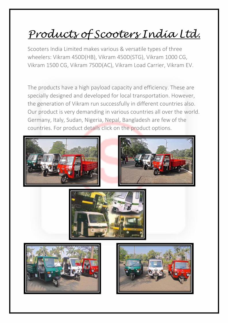
Products of Scooters India Ltd.
Scooters India Limited makes various & versatile types of three
wheelers: Vikram 450D(HB), Vikram 450D(STG), Vikram 1000 CG,
Vikram 1500 CG, Vikram 750D(AC), Vikram Load Carrier, Vikram EV.
The products have a high payload capacity and efficiency. These are
specially designed and developed for local transportation. However,
the generation of Vikram run successfully in different countries also.
Our product is very demanding in various countries all over the world.
Germany, Italy, Sudan, Nigeria, Nepal, Bangladesh are few of the
countries. For product details click on the product options.
DIFFERENTIAL
A differential is a gear train with three shafts that has the property that the angular velocity of one
shaft is the average of the angular velocities of the others, or a fixed multiple of that average.
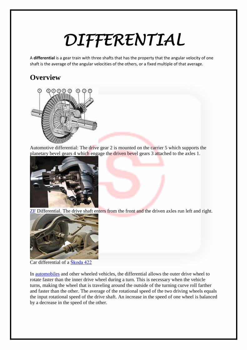
Overview
Automotive differential: The drive gear 2 is mounted on the carrier 5 which supports the
planetary bevel gears 4 which engage the driven bevel gears 3 attached to the axles 1.
ZF Differential. The drive shaft enters from the front and the driven axles run left and right.
Car differential of a Škoda 422
In automobiles and other wheeled vehicles, the differential allows the outer drive wheel to
rotate faster than the inner drive wheel during a turn. This is necessary when the vehicle
turns, making the wheel that is traveling around the outside of the turning curve roll farther
and faster than the other. The average of the rotational speed of the two driving wheels equals
the input rotational speed of the drive shaft. An increase in the speed of one wheel is balanced
by a decrease in the speed of the other.
When used in this way, a differential couples the input shaft (or prop shaft) to the pinion,
which in turn runs on the crown wheel of the differential. This also works as reduction
gearing to give the ratio. On rear wheel drive vehicles the differential may connect to half-
shafts inside an axle casing or drive shafts that connect to the rear driving wheels. Front
wheel drive vehicles tend to have the pinion on the end of the main-shaft of the gearbox and
the differential is enclosed in the same casing as the gearbox. They have individual drive-
shafts to each wheel. Older 4x4 vehicles and tractors usually have a solid front axle, the
modern way can be a separate differential and drive shaft arrangement for the front.
A differential consists of one input, the drive shaft, and two outputs which are the two drive
wheels, however the rotation of the drive wheels are coupled by their connection to the
roadway. Under normal conditions, with small tyre slip, the ratio of the speeds of the two
driving wheels is defined by the ratio of the radii of the paths around which the two wheels
are rolling, which in turn is determined by the track-width of the vehicle (the distance
between the driving wheels) and the radius of the turn.
Non-automotive uses of differentials include performing analog arithmetic. Two of the
differential's three shafts are made to rotate through angles that represent (are proportional to)
two numbers, and the angle of the third shaft's rotation represents the sum or difference of the
two input numbers. The earliest known use of a differential gear is in the Antikythera
mechanism, circa 80 BCE, which used a differential gear to control a small sphere
representing the moon from the difference between the sun and moon position pointers. The
ball was painted black and white in hemispheres, and graphically showed the phase of the
moon at a particular point in time.[1] See also the Chinese South-pointing chariot. An equation
clock that used a differential for addition was made in 1720. In the 20th Century, large
assemblies of many differentials were used as analog computers, calculating, for example, the
direction in which a gun should be aimed. However, the development of electronic digital
computers has made these uses of differentials obsolete. Military uses may still exist. See
Electromagnetic pulse. Practically all the differentials that are now made are used in
automobiles and similar vehicles.
History
There are many claims to the invention of the differential gear, but it is possible that it was
known, at least in some places, in ancient times. Some historical milestones of the differential
include:
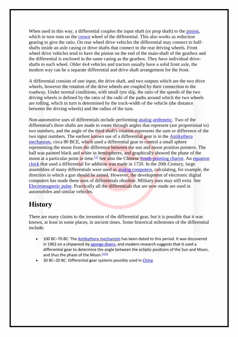
100 BC–70 BC: The Antikythera mechanism has been dated to this period. It was discovered in 1902 on a shipwreck by sponge divers, and modern research suggests that it used a differential gear to determine the angle between the ecliptic positions of the Sun and Moon, and thus the phase of the Moon.[1][2]
30 BC–20 BC: Differential gear systems possibly used in China
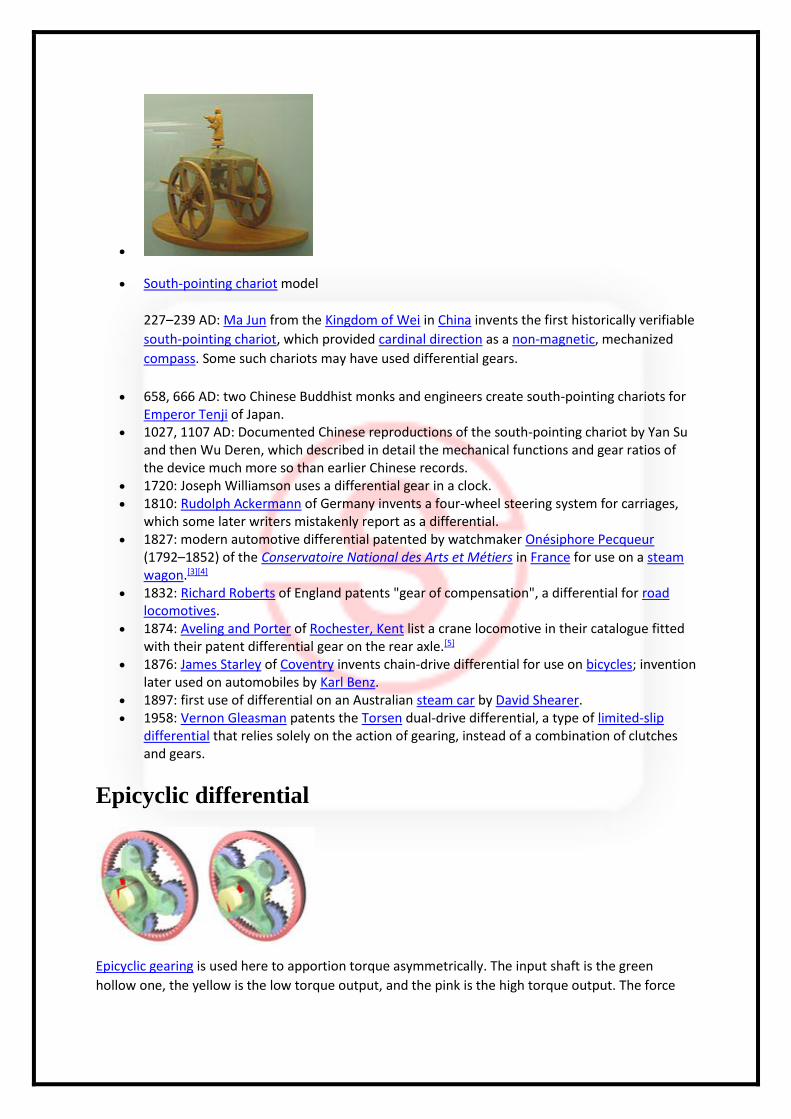
South-pointing chariot model
227–239 AD: Ma Jun from the Kingdom of Wei in China invents the first historically verifiable
south-pointing chariot, which provided cardinal direction as a non-magnetic, mechanized
compass. Some such chariots may have used differential gears.
658, 666 AD: two Chinese Buddhist monks and engineers create south-pointing chariots for Emperor Tenji of Japan.
1027, 1107 AD: Documented Chinese reproductions of the south-pointing chariot by Yan Su and then Wu Deren, which described in detail the mechanical functions and gear ratios of the device much more so than earlier Chinese records.
1720: Joseph Williamson uses a differential gear in a clock. 1810: Rudolph Ackermann of Germany invents a four-wheel steering system for carriages,
which some later writers mistakenly report as a differential. 1827: modern automotive differential patented by watchmaker Onésiphore Pecqueur
(1792–1852) of the Conservatoire National des Arts et Métiers in France for use on a steam wagon.[3][4]
1832: Richard Roberts of England patents "gear of compensation", a differential for road locomotives.
1874: Aveling and Porter of Rochester, Kent list a crane locomotive in their catalogue fitted with their patent differential gear on the rear axle.[5]
1876: James Starley of Coventry invents chain-drive differential for use on bicycles; invention later used on automobiles by Karl Benz.
1897: first use of differential on an Australian steam car by David Shearer. 1958: Vernon Gleasman patents the Torsen dual-drive differential, a type of limited-slip
differential that relies solely on the action of gearing, instead of a combination of clutches and gears.
Epicyclic differential
Epicyclic gearing is used here to apportion torque asymmetrically. The input shaft is the green
hollow one, the yellow is the low torque output, and the pink is the high torque output. The force
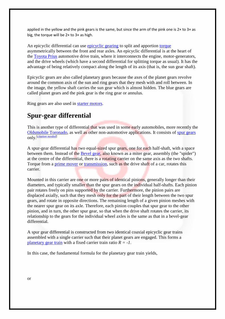
applied in the yellow and the pink gears is the same, but since the arm of the pink one is 2× to 3× as
big, the torque will be 2× to 3× as high.
An epicyclic differential can use epicyclic gearing to split and apportion torque
asymmetrically between the front and rear axles. An epicyclic differential is at the heart of
the Toyota Prius automotive drive train, where it interconnects the engine, motor-generators,
and the drive wheels (which have a second differential for splitting torque as usual). It has the
advantage of being relatively compact along the length of its axis (that is, the sun gear shaft).
Epicyclic gears are also called planetary gears because the axes of the planet gears revolve
around the common axis of the sun and ring gears that they mesh with and roll between. In
the image, the yellow shaft carries the sun gear which is almost hidden. The blue gears are
called planet gears and the pink gear is the ring gear or annulus.
Ring gears are also used in starter motors.
Spur-gear differential
This is another type of differential that was used in some early automobiles, more recently the
Oldsmobile Toronado, as well as other non-automotive applications. It consists of spur gears
only.[citation needed]
A spur-gear differential has two equal-sized spur gears, one for each half-shaft, with a space
between them. Instead of the Bevel gear, also known as a miter gear, assembly (the "spider")
at the centre of the differential, there is a rotating carrier on the same axis as the two shafts.
Torque from a prime mover or transmission, such as the drive shaft of a car, rotates this
carrier.
Mounted in this carrier are one or more pairs of identical pinions, generally longer than their
diameters, and typically smaller than the spur gears on the individual half-shafts. Each pinion
pair rotates freely on pins supported by the carrier. Furthermore, the pinion pairs are
displaced axially, such that they mesh only for the part of their length between the two spur
gears, and rotate in opposite directions. The remaining length of a given pinion meshes with
the nearer spur gear on its axle. Therefore, each pinion couples that spur gear to the other
pinion, and in turn, the other spur gear, so that when the drive shaft rotates the carrier, its
relationship to the gears for the individual wheel axles is the same as that in a bevel-gear
differential.
A spur gear differential is constructed from two identical coaxial epicyclic gear trains
assembled with a single carrier such that their planet gears are engaged. This forms a
planetary gear train with a fixed carrier train ratio R = -1.
In this case, the fundamental formula for the planetary gear train yields,
or
Thus, the angular velocity of the carrier of a spur gear differential is the average of the
angular velocities of the sun and annular gears.[6]
In discussing the spur gear differential, the use of the term annular gear is a convenient way
to distinguish the sun gears of the two epicyclic gear trains. The second sun gear serves the
same purpose as the annular gear of a simple planetary gear train, but clearly does not have
the internal gear mate that is typical of an annular gear.
Non-automotive applications
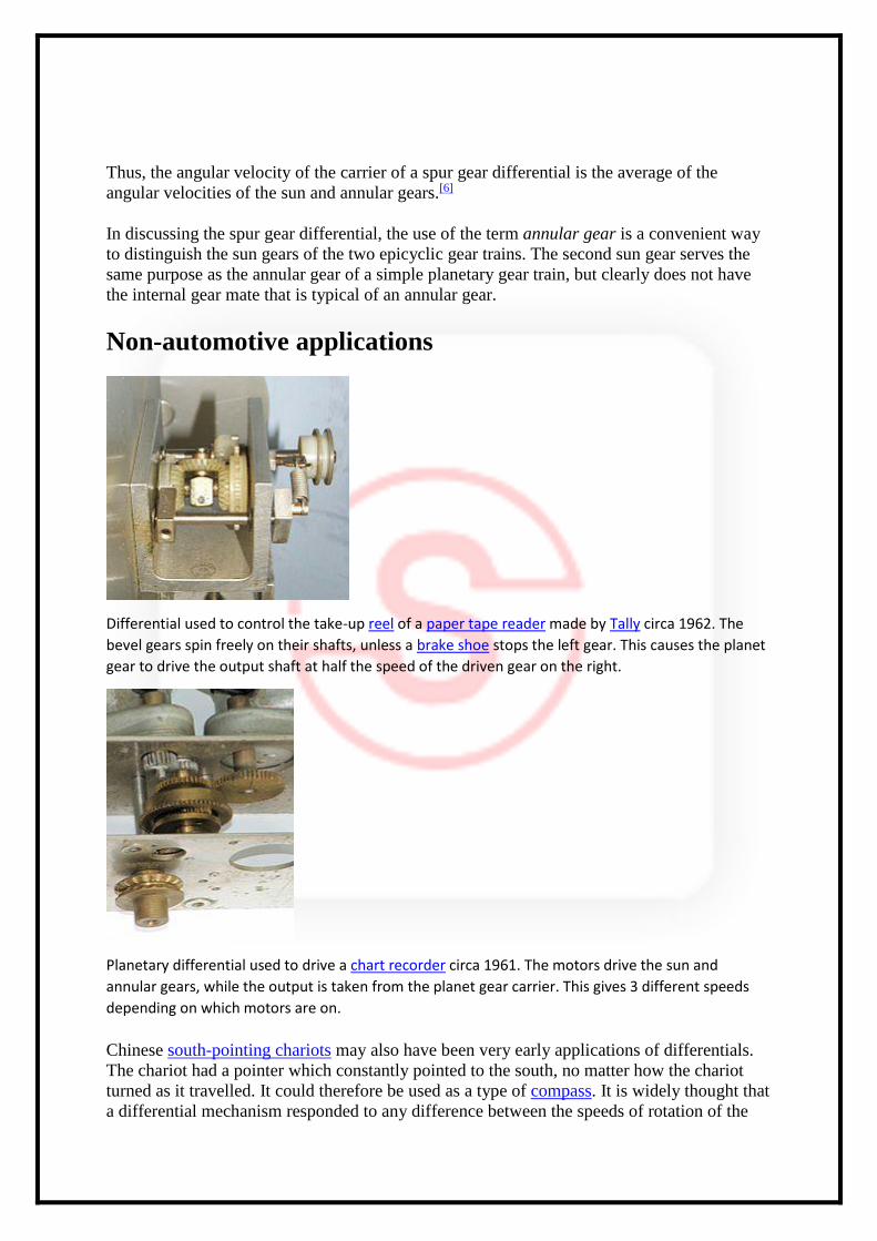
Differential used to control the take-up reel of a paper tape reader made by Tally circa 1962. The
bevel gears spin freely on their shafts, unless a brake shoe stops the left gear. This causes the planet
gear to drive the output shaft at half the speed of the driven gear on the right.
Planetary differential used to drive a chart recorder circa 1961. The motors drive the sun and
annular gears, while the output is taken from the planet gear carrier. This gives 3 different speeds
depending on which motors are on.
Chinese south-pointing chariots may also have been very early applications of differentials.
The chariot had a pointer which constantly pointed to the south, no matter how the chariot
turned as it travelled. It could therefore be used as a type of compass. It is widely thought that
a differential mechanism responded to any difference between the speeds of rotation of the
two wheels of the chariot, and turned the pointer appropriately. However, the mechanism was
not precise enough, and, after a few miles of travel, the dial could have very well been
pointing in the complete opposite direction.
The earliest definitely verified use of a differential was in a clock made by Joseph
Williamson in 1720. It employed a differential to add the equation of time to local mean time,
as determined by the clock mechanism, to produce solar time, which would have been the
same as the reading of a sundial. During the 18th Century, sundials were considered to show
the "correct" time, so an ordinary clock would frequently have to be readjusted, even if it
worked perfectly, because of seasonal variations in the equation of time. Williamson's and
other equation clocks showed sundial time without needing readjustment. Nowadays, we
consider clocks to be "correct" and sundials usually incorrect, so many sundials carry
instructions about how to use their readings to obtain clock time.
In the first half of the twentieth century, mechanical analog computers, called differential
analyzers, were constructed that used differential gear trains to perform addition and
subtraction. The U.S. Navy Mk.1 gun fire control computer used about 160 differentials of
the bevel-gear type.
A differential gear train can be used to allow a difference between two input axles. Mills
often used such gears to apply torque in the required axis. Differentials are also used in this
way in watchmaking to link two separate regulating systems with the aim of averaging out
errors. Greubel Forsey use a differential to link two double tourbillon systems in their
Quadruple Differential Tourbillon.
Application to vehicles
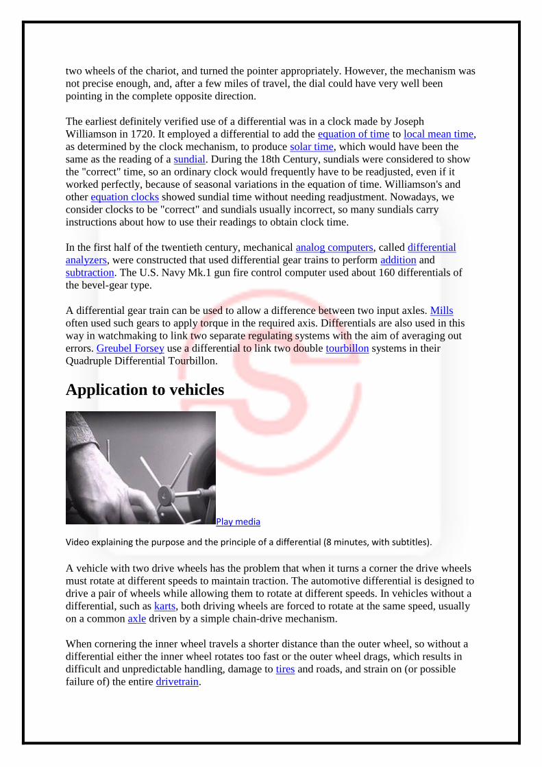
Play media
Video explaining the purpose and the principle of a differential (8 minutes, with subtitles).
A vehicle with two drive wheels has the problem that when it turns a corner the drive wheels
must rotate at different speeds to maintain traction. The automotive differential is designed to
drive a pair of wheels while allowing them to rotate at different speeds. In vehicles without a
differential, such as karts, both driving wheels are forced to rotate at the same speed, usually
on a common axle driven by a simple chain-drive mechanism.
When cornering the inner wheel travels a shorter distance than the outer wheel, so without a
differential either the inner wheel rotates too fast or the outer wheel drags, which results in
difficult and unpredictable handling, damage to tires and roads, and strain on (or possible
failure of) the entire drivetrain.
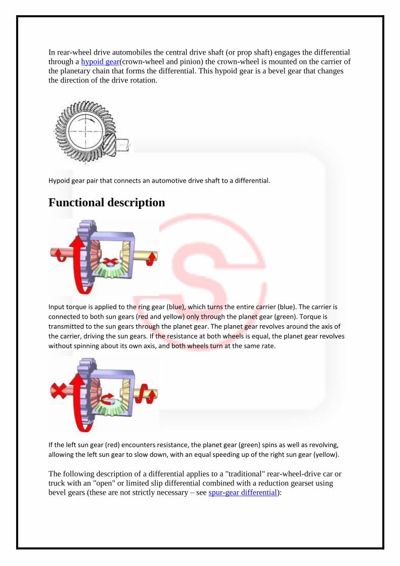
In rear-wheel drive automobiles the central drive shaft (or prop shaft) engages the differential
through a hypoid gear(crown-wheel and pinion) the crown-wheel is mounted on the carrier of
the planetary chain that forms the differential. This hypoid gear is a bevel gear that changes
the direction of the drive rotation.
Hypoid gear pair that connects an automotive drive shaft to a differential.
Functional description
Input torque is applied to the ring gear (blue), which turns the entire carrier (blue). The carrier is
connected to both sun gears (red and yellow) only through the planet gear (green). Torque is
transmitted to the sun gears through the planet gear. The planet gear revolves around the axis of
the carrier, driving the sun gears. If the resistance at both wheels is equal, the planet gear revolves
without spinning about its own axis, and both wheels turn at the same rate.
If the left sun gear (red) encounters resistance, the planet gear (green) spins as well as revolving,
allowing the left sun gear to slow down, with an equal speeding up of the right sun gear (yellow).
The following description of a differential applies to a "traditional" rear-wheel-drive car or
truck with an "open" or limited slip differential combined with a reduction gearset using
bevel gears (these are not strictly necessary – see spur-gear differential):
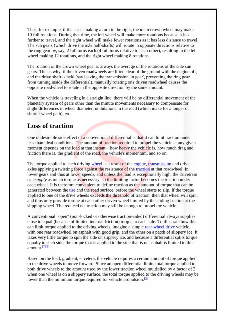
Thus, for example, if the car is making a turn to the right, the main crown wheel may make
10 full rotations. During that time, the left wheel will make more rotations because it has
further to travel, and the right wheel will make fewer rotations as it has less distance to travel.
The sun gears (which drive the axle half-shafts) will rotate in opposite directions relative to
the ring gear by, say, 2 full turns each (4 full turns relative to each other), resulting in the left
wheel making 12 rotations, and the right wheel making 8 rotations.
The rotation of the crown wheel gear is always the average of the rotations of the side sun
gears. This is why, if the driven roadwheels are lifted clear of the ground with the engine off,
and the drive shaft is held (say leaving the transmission 'in gear', preventing the ring gear
from turning inside the differential), manually rotating one driven roadwheel causes the
opposite roadwheel to rotate in the opposite direction by the same amount.
When the vehicle is traveling in a straight line, there will be no differential movement of the
planetary system of gears other than the minute movements necessary to compensate for
slight differences in wheel diameter, undulations in the road (which make for a longer or
shorter wheel path), etc.
Loss of traction
One undesirable side effect of a conventional differential is that it can limit traction under
less than ideal conditions. The amount of traction required to propel the vehicle at any given
moment depends on the load at that instant—how heavy the vehicle is, how much drag and
friction there is, the gradient of the road, the vehicle's momentum, and so on.
The torque applied to each driving wheel is a result of the engine, transmission and drive
axles applying a twisting force against the resistance of the traction at that roadwheel. In
lower gears and thus at lower speeds, and unless the load is exceptionally high, the drivetrain
can supply as much torque as necessary, so the limiting factor becomes the traction under
each wheel. It is therefore convenient to define traction as the amount of torque that can be
generated between the tire and the road surface, before the wheel starts to slip. If the torque
applied to one of the drive wheels exceeds the threshold of traction, then that wheel will spin,
and thus only provide torque at each other driven wheel limited by the sliding friction at the
slipping wheel. The reduced net traction may still be enough to propel the vehicle.
A conventional "open" (non-locked or otherwise traction-aided) differential always supplies
close to equal (because of limited internal friction) torque to each side. To illustrate how this
can limit torque applied to the driving wheels, imagine a simple rear-wheel drive vehicle,
with one rear roadwheel on asphalt with good grip, and the other on a patch of slippery ice. It
takes very little torque to spin the side on slippery ice, and because a differential splits torque
equally to each side, the torque that is applied to the side that is on asphalt is limited to this
amount.[7][8]
Based on the load, gradient, et cetera, the vehicle requires a certain amount of torque applied
to the drive wheels to move forward. Since an open differential limits total torque applied to
both drive wheels to the amount used by the lower traction wheel multiplied by a factor of 2,
when one wheel is on a slippery surface, the total torque applied to the driving wheels may be
lower than the minimum torque required for vehicle propulsion.[9]
A proposed way to distribute the power to the wheels, is to use the concept of gearless
differential, of which a review has been reported by Provatidis,[10] but the various
configurations seem to correspond either to the "sliding pins and cams" type, such as the ZF
B-70 available on early VWs, or are a variation of the ball differential.
Many newer vehicles feature traction control, which partially mitigates the poor traction
characteristics of an open differential by using the anti-lock braking system to limit or stop
the slippage of the low traction wheel, increasing the torque that can be applied to both
wheels. While not as effective in propelling a vehicle under poor traction conditions as a
traction-aided differential, it is better than a simple mechanical open differential with no
electronic traction assistance.
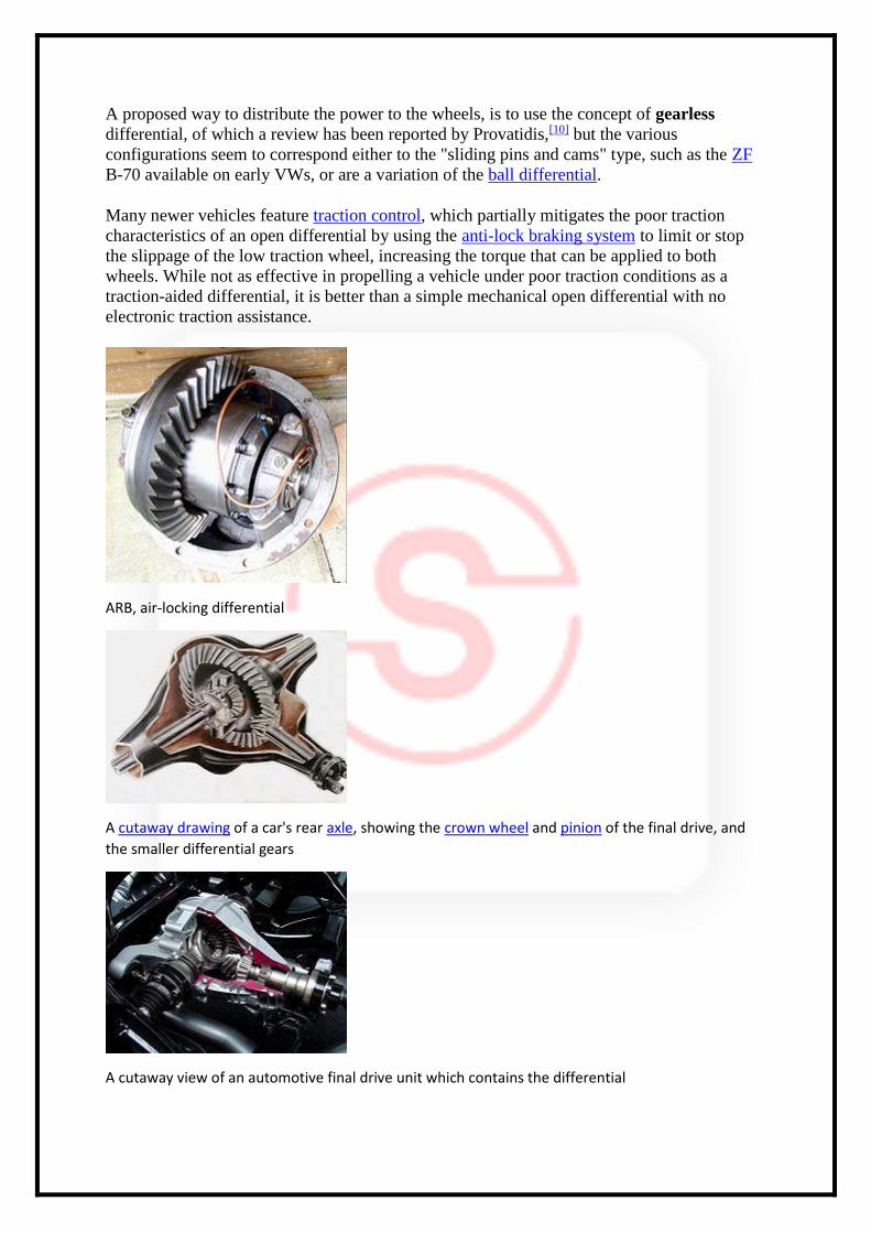
ARB, air-locking differential
A cutaway drawing of a car's rear axle, showing the crown wheel and pinion of the final drive, and
the smaller differential gears
A cutaway view of an automotive final drive unit which contains the differential
Active differentials
A relatively new technology is the electronically controlled 'active differential'. An electronic
control unit (ECU) uses inputs from multiple sensors, including yaw rate, steering input
angle, and lateral acceleration—and adjusts the distribution of torque to compensate for
undesirable handling behaviours like understeer. Active differentials used to play a large role
in the World Rally Championship, but in the 2006 season the FIA has limited the use of
active differentials only to those drivers who have not competed in the World Rally
Championship in the last five years.
Fully integrated active differentials are used on the Ferrari F430, Mitsubishi Lancer
Evolution, and on the rear wheels in the Acura RL. A version manufactured by ZF is also
being offered on the B8 chassis Audi S4 and Audi A4.[11] The Volkswagen Golf GTI Mk7 in
Performance trim also has an electronically controlled front-axle transverse differential lock,
also known as VAQ.[12]
The second constraint of the differential is passive—it is actuated by the friction kinematics
chain through the ground. The difference in torque on the roadwheels and tires (caused by
turns or bumpy ground) drives the second degree of freedom, (overcoming the torque of inner
friction) to equalise the driving torque on the tires. The sensitivity of the differential depends
on the inner friction through the second degree of freedom. All of the differentials (so called
"active" and "passive") use clutches and brakes for restricting the second degree of freedom,
so all suffer from the same disadvantage—decreased sensitivity to a dynamically changing
environment. The sensitivity of the ECU controlled differential is also limited by the time
delay caused by sensors and the response time of the actuators.
Rotation rate governing differentials
A rotation rate-governing differential eliminates the aforementioned time delay issue by
mechanically coupling the two wheels together through a set of planetary gears and then
strictly governing the allowable difference in their relative rotation rates at all times. This
forces power to be applied fully and instantly to both wheels (similar to a locking
differential), while also preserving the vehicle's cornering agility. Unlike traditional active-
differentials, these systems do not use brakes, clutch packs, or any other friction parts to
respond to wheel slip. Instead, they use a small, low-speed stepper motor to keep the
differential rotation rates of the wheels within a plausible bound for the given steering
angle.[13]
Automobiles without differentials
Although most automobiles in the developed world use differentials there are a few that do
not. Several different types exist:
Race cars and trucks in certain classes. Drag racing is done in a straight line (and often on a prepared surface), which obviates the need for a differential. A spool is used to make a solid connection between both drive wheels, which is simpler and less likely to break under very heavy acceleration. Racing on dirt or mud tracks also allows the use of spools, because the loose surface gives way while cornering. NASCAR mandates the use of spools in their cars, which does cause axle wind-up, and degrades handling in turns. Other forms of racing
without differentials includes tractor pulling, mud bogging and other 4x4 motorsports where differential action is not needed.
Vehicles with a single driving wheel. Besides motorcycles, which are generally not classified as automobiles, this group includes most three-wheeled cars. These were quite common in Europe in the mid-20th Century, but have now become rare there. They are still common in some areas of the developing world, such as India. Some early four-wheeled cars also had only one driving wheel to avoid the need for a differential. However, this arrangement led to many problems. The system was unbalanced, the driving wheel would easily spin, etc.. Because of these problems, few such vehicles were made.
Vehicles using two freewheels. A freewheel, as used on a pedal bicycle for example, allows a road wheel to rotate faster than the mechanism that drives it, allowing a cyclist to stop pedalling while going downhill. Some early automobiles had the engine driving two freewheels, one for each driving road wheel. When the vehicle turned, the engine would continue to drive the wheel on the inside of the curve, but the wheel on the outside was permitted to rotate faster by its freewheel. Thus, while turning, the vehicle had only one driving wheel. Driving in reverse is also impossible as is engine braking due to the freewheels.
Vehicles with continuously variable transmissions, such as the DAF Daffodil. The Daffodil, and other similar vehicles which were made until the 1970s by the Dutch company DAF, had a type of transmission that used an arrangement of belts and pulleys to provide an infinite number of gear ratios. The engine drove two separate transmissions which ran the two driving wheels. When the vehicle turned, the two wheels could rotate at different speeds, making the two transmissions shift to different gear ratios, thus functionally substituting for a differential. The slower moving wheel received more driving torque than the faster one, so the system had limited-slip characteristics. The duplication also provided redundancy. If one belt broke, the vehicle could still be driven.
Light vehicles with closely spaced rear wheels, such as the Isetta and Opperman Unicar, or very low mass vehicles.
Vehicles with separate motors for the driving wheels. Electric cars can have a separate motor for each driving wheel, eliminating the need for a differential, but usually with some form of gearing at each motor to get the large wheel torques necessary. A multi-motor electric vehicle such as the Dual Motor Tesla Model S can electronically control the power distribution between the motors on a millisecond scale, in this case acting as a centre differential where open differentials are still employed left-to-right.[14]
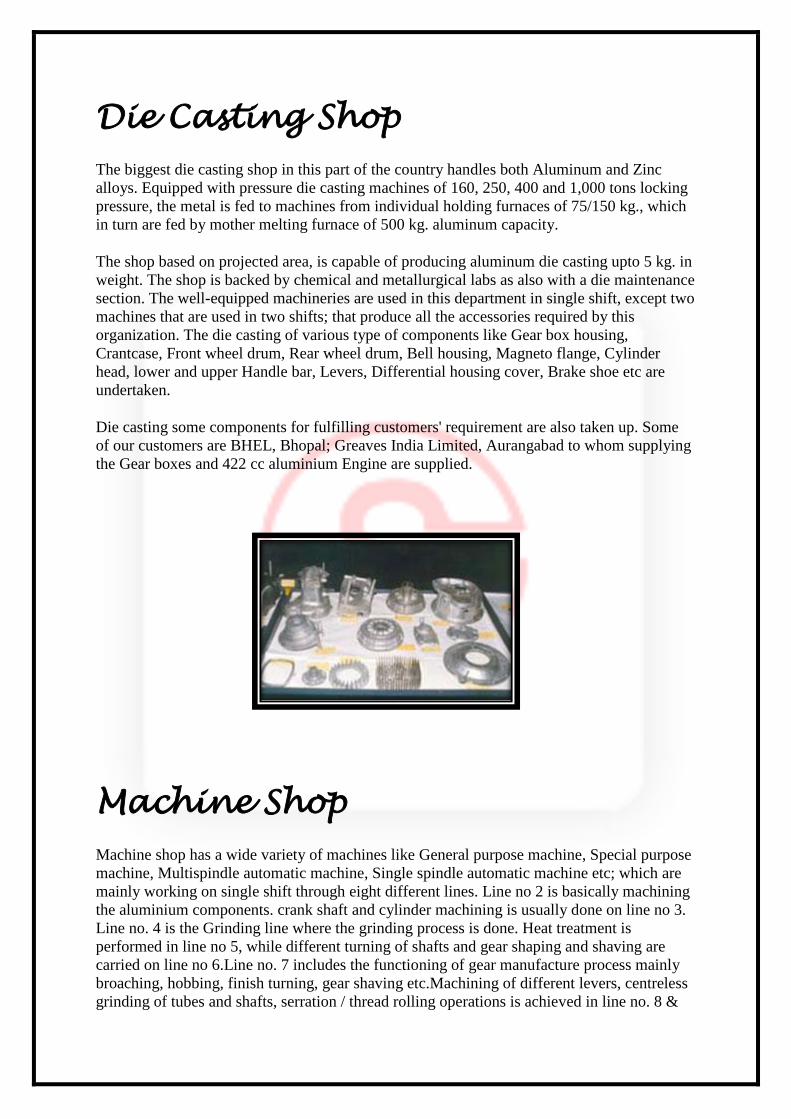
Foundry Shop
The foundry, most modern in this part of the country, can produce all grades of grey cast iron
as well as S. G. iron. In fact, it had been innovative to find new processes of modulisation, for
which it was granted 2 patents.Equipped with an Induction Melting furnace, Shell Moulding
Machines & Core Shooters, Green Sand Moulding facilities, Isothermal Heat Treatment
Furnace, one sand muller machine, two shot blasting machine, two set jolting machines for
green sand moulding, fettling and shot blasting equipments, its normal range of production
weighs upto 8 Kgs. on a pattern plate of 450x600 mm. However, foundrymen are trained to
make casting even of 1 ton weight if emergent requirement arises.
The foundry is not fully loaded with its captive requirement. Spare capacity is utilised for
producing sophisticated castings of prestigious customers like BHEL, Indian Railways,
Aerospace, Brakes India Limited, Crompton Greaves limited.The induction furnace has a
capacity of 1.3 tons. The two types of moulding is been done here. 1. Shell moulding 2.
Green sand moulding. The foundry can manufacture a wide range of products namely
Differential housing, Differential cages, Power transimission wheel, Crankcase flange,
Magneto motor, Engine output flange, Adapter plate for electric vehicle, Cylinder for both
Vikram 410 petrol version and Vikram 750 diesel version
Foundry Shop
Die Casting
Shop
Machine Shop
Paint Shop
Vehical Assembly
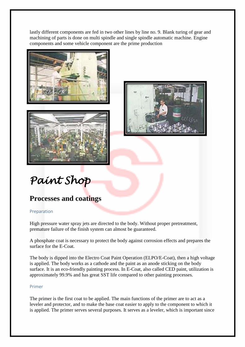
Die Casting Shop
The biggest die casting shop in this part of the country handles both Aluminum and Zinc
alloys. Equipped with pressure die casting machines of 160, 250, 400 and 1,000 tons locking
pressure, the metal is fed to machines from individual holding furnaces of 75/150 kg., which
in turn are fed by mother melting furnace of 500 kg. aluminum capacity.
The shop based on projected area, is capable of producing aluminum die casting upto 5 kg. in
weight. The shop is backed by chemical and metallurgical labs as also with a die maintenance
section. The well-equipped machineries are used in this department in single shift, except two
machines that are used in two shifts; that produce all the accessories required by this
organization. The die casting of various type of components like Gear box housing,
Crantcase, Front wheel drum, Rear wheel drum, Bell housing, Magneto flange, Cylinder
head, lower and upper Handle bar, Levers, Differential housing cover, Brake shoe etc are
undertaken.
Die casting some components for fulfilling customers' requirement are also taken up. Some
of our customers are BHEL, Bhopal; Greaves India Limited, Aurangabad to whom supplying
the Gear boxes and 422 cc aluminium Engine are supplied.
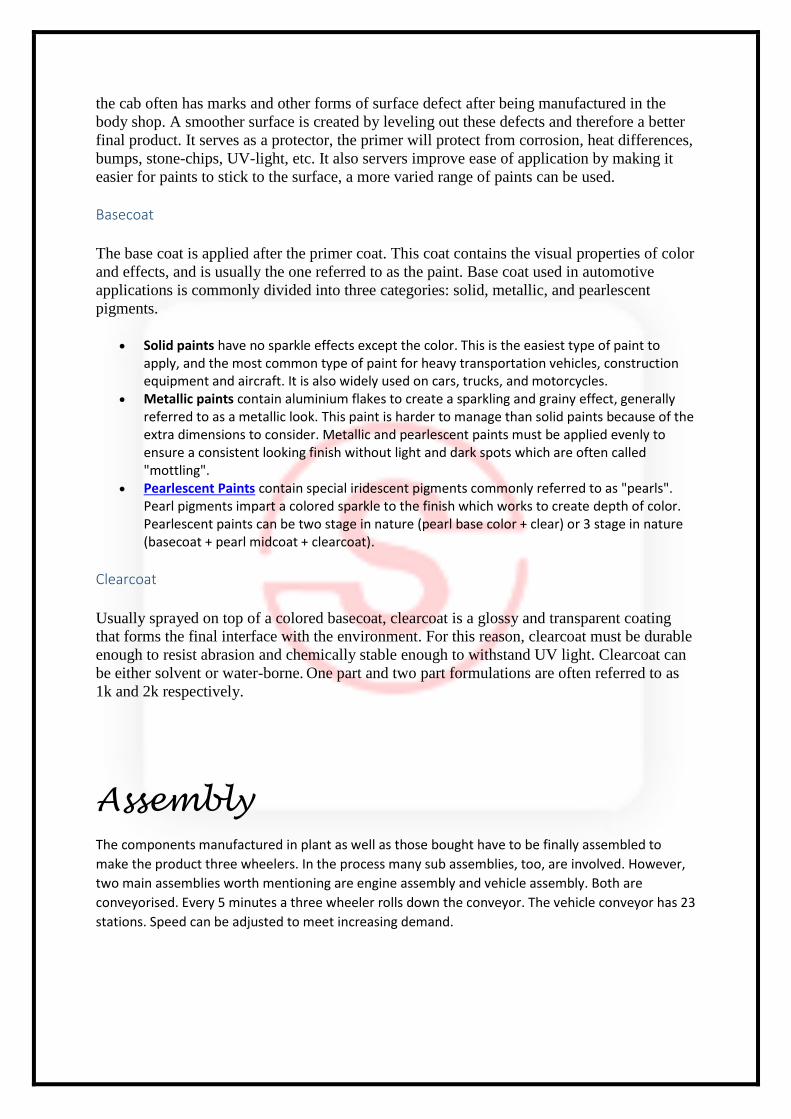
Machine Shop
Machine shop has a wide variety of machines like General purpose machine, Special purpose
machine, Multispindle automatic machine, Single spindle automatic machine etc; which are
mainly working on single shift through eight different lines. Line no 2 is basically machining
the aluminium components. crank shaft and cylinder machining is usually done on line no 3.
Line no. 4 is the Grinding line where the grinding process is done. Heat treatment is
performed in line no 5, while different turning of shafts and gear shaping and shaving are
carried on line no 6.Line no. 7 includes the functioning of gear manufacture process mainly
broaching, hobbing, finish turning, gear shaving etc.Machining of different levers, centreless
grinding of tubes and shafts, serration / thread rolling operations is achieved in line no. 8 &
lastly different components are fed in two other lines by line no. 9. Blank turing of gear and
machining of parts is done on multi spindle and single spindle automatic machine. Engine
components and some vehicle component are the prime production
Paint Shop
Processes and coatings
Preparation
High pressure water spray jets are directed to the body. Without proper pretreatment,
premature failure of the finish system can almost be guaranteed.
A phosphate coat is necessary to protect the body against corrosion effects and prepares the
surface for the E-Coat.
The body is dipped into the Electro Coat Paint Operation (ELPO/E-Coat), then a high voltage
is applied. The body works as a cathode and the paint as an anode sticking on the body
surface. It is an eco-friendly painting process. In E-Coat, also called CED paint, utilization is
approximately 99.9% and has great SST life compared to other painting processes.
Primer
The primer is the first coat to be applied. The main functions of the primer are to act as a
leveler and protector, and to make the base coat easier to apply to the component to which it
is applied. The primer serves several purposes. It serves as a leveler, which is important since
the cab often has marks and other forms of surface defect after being manufactured in the
body shop. A smoother surface is created by leveling out these defects and therefore a better
final product. It serves as a protector, the primer will protect from corrosion, heat differences,
bumps, stone-chips, UV-light, etc. It also servers improve ease of application by making it
easier for paints to stick to the surface, a more varied range of paints can be used.
Basecoat
The base coat is applied after the primer coat. This coat contains the visual properties of color
and effects, and is usually the one referred to as the paint. Base coat used in automotive
applications is commonly divided into three categories: solid, metallic, and pearlescent
pigments.
Solid paints have no sparkle effects except the color. This is the easiest type of paint to apply, and the most common type of paint for heavy transportation vehicles, construction equipment and aircraft. It is also widely used on cars, trucks, and motorcycles.
Metallic paints contain aluminium flakes to create a sparkling and grainy effect, generally referred to as a metallic look. This paint is harder to manage than solid paints because of the extra dimensions to consider. Metallic and pearlescent paints must be applied evenly to ensure a consistent looking finish without light and dark spots which are often called "mottling".
Pearlescent Paints contain special iridescent pigments commonly referred to as "pearls". Pearl pigments impart a colored sparkle to the finish which works to create depth of color. Pearlescent paints can be two stage in nature (pearl base color + clear) or 3 stage in nature (basecoat + pearl midcoat + clearcoat).
Clearcoat
Usually sprayed on top of a colored basecoat, clearcoat is a glossy and transparent coating
that forms the final interface with the environment. For this reason, clearcoat must be durable
enough to resist abrasion and chemically stable enough to withstand UV light. Clearcoat can
be either solvent or water-borne. One part and two part formulations are often referred to as
1k and 2k respectively.
Assembly
The components manufactured in plant as well as those bought have to be finally assembled to
make the product three wheelers. In the process many sub assemblies, too, are involved. However,
two main assemblies worth mentioning are engine assembly and vehicle assembly. Both are
conveyorised. Every 5 minutes a three wheeler rolls down the conveyor. The vehicle conveyor has 23
stations. Speed can be adjusted to meet increasing demand.
Future Planning of Scooters India Ltd
Past is dead and gone, we are standing on the threshold of today, planning for the future. In
the process we added one wheel, shifting the gear from two wheeler to three wheeler and
propose to add another, entering in to the arena of four wheeler, though for a limited segment
- the segment of zero emission. The quality has moved from product to process to people.
Only good quality people can work out quality processes and provide quality products and
services.
Environment is our greatest heritage and its protection, our highest responsiblity. Green
process design as also green product design have assumed importance. Eco-design of the
products and process is the task for tomorrow. Accordingly, product development is the
obsession for future. Engineering it through various processes not only to meet but exceed
customer's expectation is the challenge.
As the 21st century is knocking at the door, the demand from people will increase manifolds.
Keeping this in view, the company has made HRD a key functional area. The real asset has
shifted from plant and machinery to brands and brains. Knowledge has become the biggest
value adder. Accordingly, sufficient resources have been committed to convert the company
into a learning organisation, thirsty for knowledge.
Growing into a global company is not only a goal but has become necessity as the world has
turned into a global village without boundaries and there is no place in the global village for
protection.
Vision & Mission of Scooters India ltd.
Mission
To fulfill customer's needs for economic and safe mode of road transport and quality
engineering products through contemporary technologies.
Vision
To grow into an environment friendly and globally competitive company constantly striving
to meet the changing needs of customer through constantly improving existing products,
adding new products and expanding customer base.
Objective
Providing economical and safe means of transportation with contemporary technology for
movement of cargo and people.Providing eco-friendly, flawless and reliable products to
fulfill customer needs. Achieving customer satisfaction by providing products at right price
and at right time.
Conclusion
It may be fact that my training has come to an end, but the experience here and
what I learned here is going to with me for all my life. The experience was truly
working under the guidance of Mr Raghavendra Satyarthi sir. I am to compile and
present you the project on “DIFFERENTIAL”.
All the data in this project has been taken from the source within “Scooters India
Ltd.”.
The theoretical part of the project is presentation of what I learnt here at
“Scooters India Ltd.” during my project training period.
Altaf Nazeer
B.Tech 2nd year (Manufacturing Engineering)
Central Institute of Plastic Engineering & Technology, Lucknow