Embed Size (px)
Citation preview

Tengiz oilfield simulation techniques
Scientific Research Institute of Production and Drilling Technologies «KazMunayGas»
Akzhan Kassenov
Outline
Short description of the fieldModel descriptionModel runningHistory matching – hydraulic flow units Conclusion

Short description of the field
One of the deepest giant oil fields in the worldOil saturated thickness – 1600 metersMore than 100 wells Production since 1993 Reserves X billion tons of oil 2 marathon course to run around the
field

Short description of geology
Reservoir – carbonaceous: Unit I (bashkirian-serpukhovian
deposits) Unit II (lower visean-tournasian
deposits) Unit III (Devonian deposits)
Three units make one hydrodynamic system
Two main zones were selected: platform and slope
Поперечный профиль пластового давления

Creation of simulation model and recreation of historic production data
and bottom hole pressure

Short description of the model
Number of active cells – more than 1 million Carbonate reservoir with fractures on
slopes Dual porosity and dual permeability
model Low matrix permeability Fluid model: 8 components with high
H2S content VFP for wells
6

Model building methodology
Grid modelling and layering process
Reservoir description(upscaling and selection of
effective cell parameters: φ, k, NTG)
Relative permeability curves and capillary
pressure curves
Fluid parameter (PVT model)
Water drive system modeling
Well modeling (coordinates, construction, perforations)
Definition of well parameters in
accordance with history data
Optimization process to decrease model run
timeHistory matching Definition of various
prediction cases
Correction of certain geologic parameters
History matching of well by well production rates
History matching of well by well bottom hole pressure

Difficulties in building of Tengizsimulation model
2) Vpor1>>> Vpor2
∆t <<< 1
1) Vpor1 ≈ Vpor2
∆t = 1
Integrated approach in “matrix-fracture” system modeling Significant difference in porosity and permeability of “matrix-fracture”
system
Displacement mechanism: oil moves frommatrix cell to fracture cell
Significant difference between pore volumeresults in decrease of simulation model timestep

Difficulties in building of Tengizsimulation model
Decrease of simulation model time step results in big amount of consecutive model iterations (Newtonian iterations) in order to historymatch. Simulation becomes even more complicated when injection phase begins.
Gas injection

Appropriate program choice
Reasons of increasing the model run time
Dual porosity and dual permeability Elaborate structural modelGas reinjectionGigantic size Compositional model with big number of components

Comparison of run time spent with INTERSECT and E300 using cluster (72 cores)
5 hours
30 hours

History matching methodics

Standard approach for permeability calculation
Porosity from permeability dependence graph
Correlation coefficient
Permeability coefficient dependence from porosity
Created separately for each horizon

14
Separation of petrophysical properties on HFU(hydraulic flow units)
6744 values (by wells)
SPE 63072 “Effective petrophysical fracture characterization using the flow unit concept”, J.G.Rincones, R.Delgado, H.Oheh, P.Enwere
Perm
eabi
lity,
mD
Porosity, mD

Cum
ulat
ive
prob
abili
ty, F
zi
Step Fzi15
Separation of petrophysical properties on HFU(hydraulic flow units)

16
Separation of petrophysical properties on HFU(hydraulic flow units)
Perm
eabi
lity,
mD

HFU Characteristics
1 HFU: low Filtration and Carrying Properties (FCP)
k=0.001÷5 mD, ɸ=0.002÷0.16 Distributed at platform of all units and near basin parts of slope in the zones with low “energy” and absence of fractures; 2 HFU: low FCPk=0.001÷400 mD, ɸ=0.002÷0.18Distributed at platform and slope zones of reservoir. Reservoir type mainly porous-fractured.
17Pe
rmea
bilit
y, m
D

3 HFU: medium FCPk=0.1÷900 mD, ɸ=0.002÷0.13 Distributed at slope zone of reservoir. Reservoir type mainly fractured.
4 HFU: medium FCP
k=1÷900 mD, ɸ=0.002÷0.04Distributed at slope parts of reservoir in zones with highest angles of inclination. Reservoir type mainly fractured
18Pe
rmea
bilit
y, m
D
HFU Characteristics

Comparison of histograms of permeability models made by standard approach and by HFU
Standard approach HFU
Mean value2.63 mD
Mean value19 mD
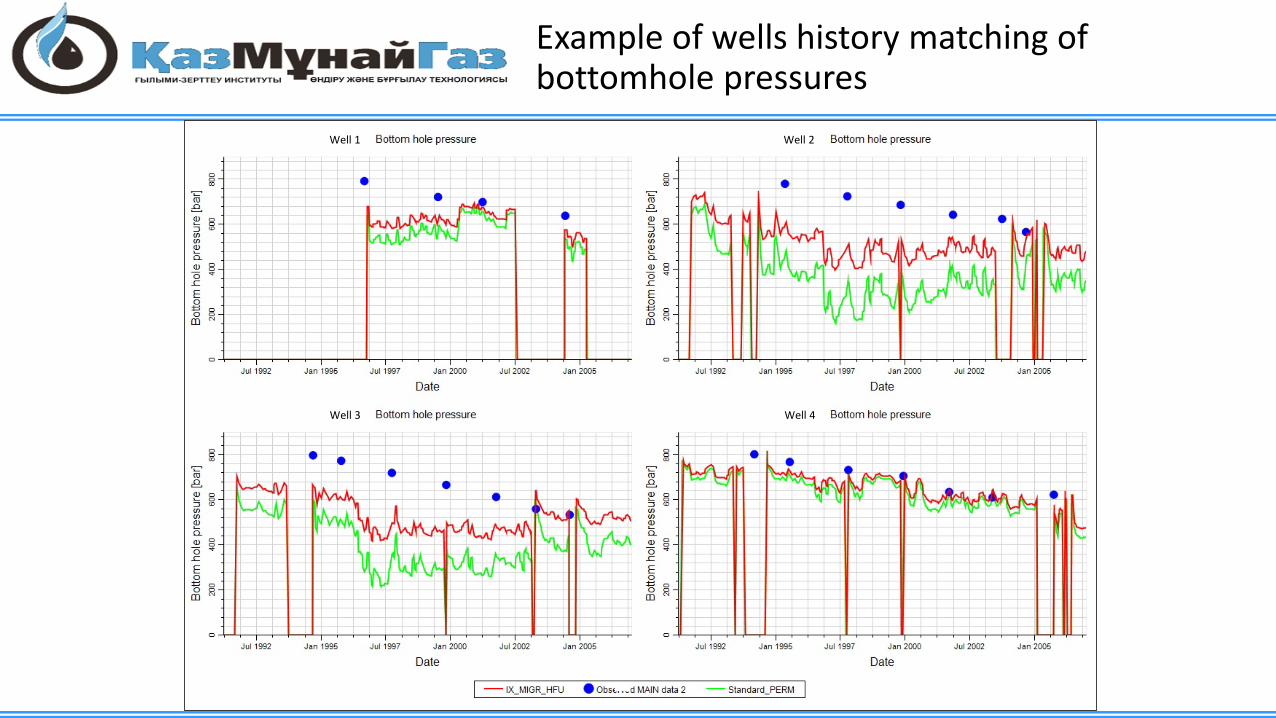
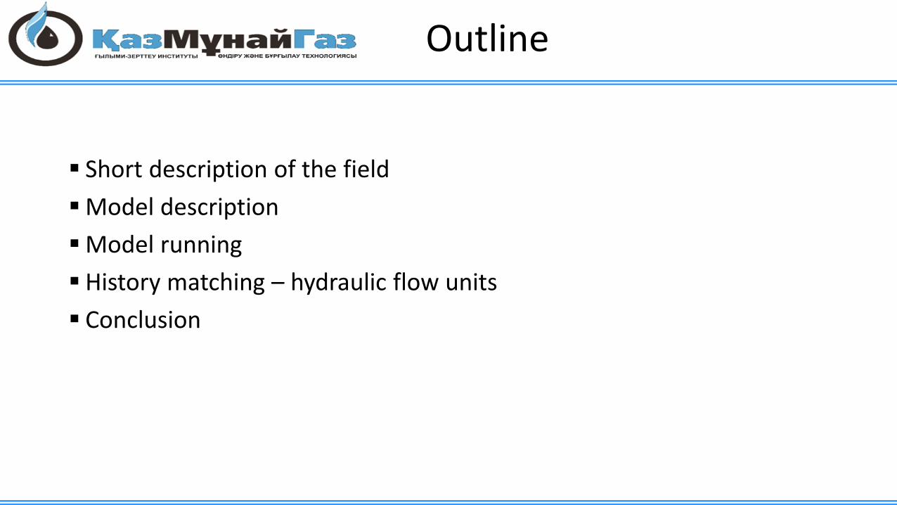
Example of wells history matching of bottomhole pressures
Well 1 Well 2
Well 3 Well 4

Comparison of bottomhole pressure values by application of different permeability models
Insufficient level of bottomholepressures matching were observed by some wells, located at zones of high FCP. Application of HFU allowed considerably improve situation
Bott
omho
lepr
essu
re (b
ar) w
ith st
anda
rd p
erm
eabi
lity
mod
el
Bottomhole pressure (bar) with HFU permeability model
«Standard» model: 320 barHFU: 460 bar

Conclusions
Tengiz field model represents a complex simulation model with maximum available software requirements needed for simulation run Implementation of INTERSECT hydrodynamic simulator considerably
reduced simulation run time and allowed to apply different history matching methods Application of HFU considerably improved history matching of
bottomhole pressuresHFU helped to qualitatively make and forecast reservoir
characterization

Thank you for attention!