Embed Size (px)
Citation preview
Programming manual
Retain for future use
Altivar 61
Variable speed drives for synchronous and asynchronous motors
Software V1.6
Courtesy of Steven Engineering, Inc.-230 Ryan Way, South San Francisco, CA 94080-6370-Main Office: (650) 588-9200-Outside Local Area: (800) 258-9200-www.stevenengineering.com

Courtesy of Steven Engineering, Inc.-230 Ryan Way, South San Francisco, CA 94080-6370-Main Office: (650) 588-9200-Outside Local Area: (800) 258-9200-www.stevenengineering.com

3
Contents
Before you begin______________________________________________________________________________________________ 4Documentation structure________________________________________________________________________________________ 5Software enhancements________________________________________________________________________________________ 6Steps for setting up the drive ____________________________________________________________________________________ 8Factory configuration __________________________________________________________________________________________ 9Setup – Preliminary recommendations____________________________________________________________________________ 10Graphic display terminal _______________________________________________________________________________________ 13
Description of the terminal _______________________________________________________________________________ 13Description of the graphic screen __________________________________________________________________________ 14First power-up – [5. LANGUAGE] menu_____________________________________________________________________ 17Subsequent power ups__________________________________________________________________________________ 18Programming: Example of accessing a parameter_____________________________________________________________ 19Quick navigation _______________________________________________________________________________________ 20
Integrated display terminal _____________________________________________________________________________________ 23Functions of the display and the keys_______________________________________________________________________ 23Accessing menus ______________________________________________________________________________________ 24Accessing menu parameters _____________________________________________________________________________ 25
[2. ACCESS LEVEL] (LAC-) ____________________________________________________________________________________ 26Structure of parameter tables ___________________________________________________________________________________ 29Interdependence of parameter values ____________________________________________________________________________ 30Finding a parameter in this document ____________________________________________________________________________ 31[1.1 SIMPLY START] (SIM-)____________________________________________________________________________________ 32[1.2 MONITORING] (SUP-) ____________________________________________________________________________________ 38[1.3 SETTINGS] (SEt-) ________________________________________________________________________________________ 47[1.4 MOTOR CONTROL] (drC-) _________________________________________________________________________________ 63[1.5 INPUTS / OUTPUTS CFG] (I-O-) ____________________________________________________________________________ 79[1.6 COMMAND] (CtL-)_______________________________________________________________________________________ 108[1.7 APPLICATION FUNCT.] (FUn-) ____________________________________________________________________________ 121[1.8 FAULT MANAGEMENT] (FLt-) _____________________________________________________________________________ 185[1.9 COMMUNICATION] (COM-) _______________________________________________________________________________ 211[1.10 DIAGNOSTICS]________________________________________________________________________________________ 215[1.11 IDENTIFICATION] ______________________________________________________________________________________ 217[1.12 FACTORY SETTINGS] (FCS-) ____________________________________________________________________________ 218[1.13 USER MENU] (USr-) ____________________________________________________________________________________ 221[1.14 PROGRAMMABLE CARD] (PLC-) _________________________________________________________________________ 222[3. OPEN / SAVE AS] ________________________________________________________________________________________ 223[4. PASSWORD] (COd-)______________________________________________________________________________________ 225[6 MONITORING CONFIG.] ___________________________________________________________________________________ 227[7 DISPLAY CONFIG.] _______________________________________________________________________________________ 231[MULTIPOINT SCREEN] _____________________________________________________________________________________ 236Maintenance _______________________________________________________________________________________________ 237Faults – Causes – Remedies __________________________________________________________________________________ 238User settings tables _________________________________________________________________________________________ 244Index of functions ___________________________________________________________________________________________ 246Index of parameter codes_____________________________________________________________________________________ 247
Courtesy of Steven Engineering, Inc.-230 Ryan Way, South San Francisco, CA 94080-6370-Main Office: (650) 588-9200-Outside Local Area: (800) 258-9200-www.stevenengineering.com

Courtes
Before you begin
Read and understand these instructions before performing any procedure with this drive.
DANGERHAZARDOUS VOLTAGE
• Read and understand the Installation Manual in full before installing or operating the ATV61 drive. Installation, adjustment, repair, and maintenance must be performed by qualified personnel.
• The user is responsible for compliance with all international and national electrical standards in force concerning protective grounding of all equipment.
• Many parts in this variable speed drive, including printed wiring boards, operate at line voltage. DO NOT TOUCH. Use only electrically insulated tools.
• DO NOT touch unshielded components or terminal strip screw connections with voltage present.
• DO NOT short across terminals PA and PC or across the DC bus capacitors.
• Install and close all the covers before applying power or starting and stopping the drive.
• Before servicing the variable speed drive- Disconnect all power.- Place a “DO NOT TURN ON” label on the variable speed drive disconnect.- Lock the disconnect in the open position.
• Disconnect all power including external control power that may be present before servicing the drive. WAIT 15 MINUTES for the DC bus capacitors to discharge. Then follow the DC bus voltage measurement procedure given in the Installation Manual to verify that the DC voltage is less than 45 Vdc. The drive LEDs are not accurate indicators of the absence of DC bus voltage.
Failure to follow these instructions can result in death or serious injury
CAUTIONDAMAGED EQUIPMENTDo not operate or install any drive that appears damaged.Failure to follow this instruction can result in equipment damage.
4y of Steven Engineering, Inc.-230 Ryan Way, South San Francisco, CA 94080-6370-Main Office: (650) 588-9200-Outside Local Area: (800) 258-9200-www.stevenengineering.com
Courtes
Documentation structure
The following Altivar 61 technical documents are available on the Telemecanique website (www.telemecanique.com) as well as on the CD-ROM supplied with the drive.
Installation ManualThis bulletin contains complete mounting and wiring instructions.
Programming ManualThis describes the functions, parameters and use of the drive terminal (integrated display terminal and graphic display terminal). The communication functions are not described in this manual, but in the manual for the bus or network used.
Communication Parameters ManualThis manual describes:
• The drive parameters with specific information for use via a bus or communication network.
• The operating modes specific to communication (state chart).
• The interaction between communication and local control.
Manuals for Modbus, CANopen, Ethernet, Profibus, INTERBUS, Uni-Telway, FIPIO and Modbus Plus, etc.These manuals describe the assembly, connection to the bus or network, signaling, diagnostics, and configuration of the communication-specific parameters via the integrated display terminal or the graphic display terminal.They also describe the communication services of the protocols.
ATV 38/ATV 61 Migration ManualThis manual describes the differences between the Altivar 61 and the Altivar 38 and explains how to replace an Altivar 38, including how to replace drives communicating on a bus or a network.
ATV 78/ATV 61/71 Migration ManualThis manual describes the differences between the Altivar 61/71 and Altivar 78 and explains how to replace an Altivar 78.
5y of Steven Engineering, Inc.-230 Ryan Way, South San Francisco, CA 94080-6370-Main Office: (650) 588-9200-Outside Local Area: (800) 258-9200-www.stevenengineering.com

Courtes
Software enhancements
Since the Altivar ATV 61 was first launched, it has benefited from the addition of several new functions. The software version is now V1.6. The old versions can be replaced by this new one without any modifications.Although this documentation relates to version V1.6, it can still be used with earlier versions, as the updates merely involve the addition of new values and parameters, and none of the parameters of the previous versions have been modified or removed.The software version is indicated on the nameplate attached to the body of the drive.
Enhancements made to version V1.2 in comparison to V1.1
New parameters and functions
Option of operating with a BACnet communication card
[1.8 FAULT MANAGEMENT] (FLt-) menu• The external fault [EXTERNAL FAULT] (EtF-) page 195 can now be configured in positive or negative logic via [External fault config.]
(LEt).
Enhancements made to version V1.4 in comparison to V1.2 Factory setting
Note: In versions V1.1 and V1.2, analog output AO1 was assigned to the motor frequency. In the new version, this output is not assigned.With the exception of this parameter, the factory setting of versions V1.1 and V1.2 remain the same in the new version. The new functions are inactive in the factory setting.
New parameters and functions
[1.2 MONITORING] (SUP-) menuAddition of states and internal values relating to the new functions described below.
[1.3 SETTINGS] (SEt-) menu• [High torque thd.] (ttH) page 59• [Low torque thd.] (ttL) page 59• [Pulse warning thd.] (FqL) page 59• [Freewheel stop Thd] (FFt) page 60
[1.4 MOTOR CONTROL] (drC-) menu• Extension of the following configurations to all drive ratings (previously limited to 45 kW (60 HP) for ATV61pppM3X and to 75 kW
(100 HP) for ATV61pppN4): synchronous motor [Sync. mot.] (SYn) page 67, sinus filter [Sinus filter] (OFI) page 75, noise reduction [Noise reduction] (nrd) page 76, braking balance [Braking balance] (bbA) page 78.
[1.5 INPUTS / OUTPUTS CFG] (I-O-) menu• [AI net. channel] (AIC1) page 89• New options for assigning relays and logic outputs, page 94: torque greater than high threshold, torque less than low threshold, motor
in forward rotation, motor in reverse rotation, measured speed threshold attained.• Analog output AO1 can now be used as a logic output and assigned to relay functions and logic outputs, page 100.• New option of modifying the scale of analog outputs, page 102, using the parameters [Scaling AOx min] (ASLx) and [Scaling AOx
max] (ASHx).• New options for assigning analog outputs page 103: signed motor torque and measured motor speed.• New options for assigning alarm groups page 107: torque greater than high threshold, torque less than low threshold, measured
speed threshold attained.
6y of Steven Engineering, Inc.-230 Ryan Way, South San Francisco, CA 94080-6370-Main Office: (650) 588-9200-Outside Local Area: (800) 258-9200-www.stevenengineering.com

Courtes
Software enhancements
[1.7 APPLICATION FUNCT.] (Fun-) menu• The summing, subtraction and multiplication reference functions can now be assigned to virtual input [Network AI] (AIU1) page 128.• New parameter [Freewheel stop Thd] (FFt) page 133 used to adjust a threshold for switching to freewheel at the end of a stop on ramp
or fast stop.• The torque limitation [TORQUE LIMITATION] (tOL-) page 164 can now be configured in whole % or in 0.1% increments using [Torque
increment] (IntP) and assigned to virtual input [Network AI] (AIU1).• New Damper control function using the [DAMPER MANAGEMENT] (dAM-) menu, page 172.• Parameter switching [PARAM. SET SWITCHING] (MLP-) page 174 can now be assigned to attained frequency thresholds [Freq. Th.
attain.] (FtA) and [Freq. Th. 2 attain.] (F2A).
[1.8 FAULT MANAGEMENT] (FLt-) menu• Option to reinitialize the drive without turning it off, via [Product reset] (rP) page 188.• Option to reinitialize the drive via a logic input without turning it off, using [Product reset assig.] (rPA) page 188.• The option to configure the "output phase loss" fault [Output Phase Loss] (OPL) page 192 to [Output cut] (OAC) has been extended
to all drive ratings (previously limited to 45 kW (60 HP) for ATV61pppM3X and 75 kW (100 HP) for ATV61pppN4).• New monitoring function based on speed measurement using "Pulse input" input page 202, via the [FREQUENCY METER] (FqF-)
menu.• The braking unit short-circuit fault can now be configured using [Brake res. fault Mgt] bUb) page 204.• The [Damper stuck] (Fd1) fault in the Damper control function can be configured via [DAMPER FAULT MGT.] (FdL-) page 209.
[7 DISPLAY CONFIG.] menu• Addition, in [7.4 KEYPAD PARAMETERS] page 235, of the [Keypad contrast] and [Keypad stand-by] parameters to adjust the contrast
and stand-by mode of the graphic display unit.
Enhancements made to version V1.5 in comparison to V1.4 Extension of the range with the addition of ATV61ppppY drives for 500 to 690 V supplies. There are no new parameters, but the adjustment ranges and factory settings of some parameters have been adapted to the new voltages.
[1.5 INPUTS / OUTPUTS CFG] (I-O-) menuIncreased adjustment range for the relay and logic output delay parameters: 0 to 60000 ms instead of 0 to 9999 ms.
[1.7 APPLICATION FUNCT.] (Fun-) menu• New parameter [Conf.sensor flow] (LnS) page 181, used to configure the zero flow sensor for positive or negative logic.
Enhancements made to version V1.6 in comparison to V1.5The communication option card APOGEE FLN P1 (VW3 A3 314) is fully supported with the version V1.6 and above of the Altivar 61 software.
7y of Steven Engineering, Inc.-230 Ryan Way, South San Francisco, CA 94080-6370-Main Office: (650) 588-9200-Outside Local Area: (800) 258-9200-www.stevenengineering.com

Courtes
Steps for setting up the drive
INSTALLATION
v 1 Consult the Installation Manual
PROGRAMMINGProcedure applicable if the factory configuration, page 9, and use of the [SIMPLY START] (SIM-) menu only are sufficient for the application.
b 2 Power up without run commandv If you are using a separate power supply
for the control section, follow the instructions on page 10.
b 3 Select the language, if the drive has a graphic display terminal
b 4 Configure the [SIMPLY START] (SIM-) menuv 2-wire or 3-wire controlv Macro configurationv Motor parameters
Perform an auto-tuning operationv Motor thermal currentv Acceleration and deceleration
rampsv Speed variation range
Tips:• Before you start programming, complete
the user setting tables, page 244.
• Perform an auto-tuning operation to optimize performance, page 36.
• If you get lost, return to the factory settings, page 220.
Note: Check that the wiring of the drive is compatible with its configuration.
b 5 Start
8y of Steven Engineering, Inc.-230 Ryan Way, South San Francisco, CA 94080-6370-Main Office: (650) 588-9200-Outside Local Area: (800) 258-9200-www.stevenengineering.com

Courtes
Factory configuration
Drive factory settingsThe Altivar 61 is factory-set for the most common operating conditions:
• Macro-configuration: Pumps/fans• Motor frequency: 50 Hz• Energy-saving variable torque applications• Normal stop mode on deceleration ramp• Stop mode in the event of a fault: freewheel• Linear, acceleration and deceleration ramps: 3 seconds• Low speed: 0 Hz• High speed: 50 Hz• Motor thermal current = rated drive current• Standstill injection braking current = 0.7 x rated drive current, for 0.5 seconds• No automatic starts after a fault• Switching frequency 2.5 kHz or 12 kHz depending on drive rating• Logic inputs:
- LI1: forward (1 operating direction), 2-wire control on transition - LI2: inactive (not assigned)- LI3: switching of 2nd speed reference- LI4: fault reset- LI5, LI6: inactive (not assigned)
• Analog inputs:- AI1: 1st speed reference 0 +10 V- AI2: 2nd speed reference 0-20 mA
• Relay R1: The contact opens in the event of a fault (or drive off)• Relay R2: The contact closes when the drive is in operation• Analog output AO1: 0-20 mA, inactive (not assigned)
If the above values are compatible with the application, the drive can be used without changing the settings.
Option card factory settingsThe option card inputs/outputs are not factory-set.
9y of Steven Engineering, Inc.-230 Ryan Way, South San Francisco, CA 94080-6370-Main Office: (650) 588-9200-Outside Local Area: (800) 258-9200-www.stevenengineering.com

Courtes
Setup – Preliminary recommendations
Turning on and configuring the drive
Separate control section power supplyOnly supply power to the power section the next time the drive is powered up when:A) The drive control section is powered independently of the power section (P24 and 0V terminals).B) Whenever an option card is added or replaced.
Power switching via line contactor
User adjustment and extension of functions• The display unit and buttons can be used to modify the settings and to extend the functions described in the following pages. • Return to factory settings is made easy by the [1.12 FACTORY SETTINGS] (FCS-) menu, see page 218.• There are three types of parameter:
- Display: Values displayed by the drive - Adjustment: Can be changed during operation or when stopped - Configuration: Can only be modified when stopped and no braking is taking place. Can be displayed during operation
DANGERUNINTENDED EQUIPMENT OPERATION
• Before turning on and configuring the Altivar 61, check that the PWR (POWER REMOVAL) input is deactivated (at state 0) in order to prevent unintended operation.
• Before turning on or on exiting the configuration menus, check that the inputs assigned to the run command are deactivated (at state 0) since they can cause the motor to start immediately.
Failure to follow these instructions will result in death or serious injury.
CAUTIONINCOMPATIBLE LINE VOLTAGEBefore turning on and configuring the drive, ensure that the line voltage is compatible with the supply voltage range shown on the drive nameplate. The drive may be damaged if the line voltage is not compatible.
Failure to follow these instructions can result in equipment damage.
CAUTIONRISK OF EQUIPMENT DAMAGE
• Avoid operating the contactor frequently (premature ageing of the filter capacitors). • Cycle times < 60 s may result in damage to the pre-charge resistor.
Failure to follow these instructions can result in equipment damage.
DANGERUNINTENDED EQUIPMENT OPERATION
• Check that changes made to the settings during operation do not present any danger.• We recommend stopping the drive before making any changes.
Failure to follow these instructions will result in death or serious injury.
10y of Steven Engineering, Inc.-230 Ryan Way, South San Francisco, CA 94080-6370-Main Office: (650) 588-9200-Outside Local Area: (800) 258-9200-www.stevenengineering.com

Courtes
Setup – Preliminary recommendations
StartingImportant:
• In factory settings mode, the motor can only be supplied with power once the “forward”, “reverse” and “DC injection stop” commands have been reset:
- On power-up or a manual fault reset or after a stop command If they have not been reset, the drive will display “nSt” but will not start.
• If the automatic restart function has been configured ([Automatic restart] (Atr) parameter in the [1.8-FAULT MANAGEMENT] (FLt-) menu, see page 189), these commands are taken into account without a reset being necessary.
Test on a low power motor or without a motor• In factory settings mode, [Output Phase Loss] detection (OPL) page 192 is active (OPL = YES). To check the drive in a test or
maintenance environment without having to switch to a motor with the same rating as the drive (particularly useful in the case of high power drives), deactivate [Output Phase Loss] (OPL = no).
• Set [Motor control type] (Ctt) = [V/F 2pts] (UF2) or [V/F 5pts] (UF5) or [U/F Quad.] (UFq) ([1.4-MOTOR CONTROL] (drC-) menu, see page 67)
Using motors in parallel• Set [Motor control type] (Ctt) = [V/F 2pts] (UF2) or [V/F 5pts] (UF5) or [U/F Quad.] (UFq) ([1.4-MOTOR CONTROL] (drC-) menu,
see page 67)
CAUTIONUNINTENDED EQUIPMENT OPERATION
Motor thermal protection will not be provided by the drive if the motor current is less than 0.2 times the rated drive current. Provide an alternative means of thermal protection.
Failure to follow these instructions can result in equipment damage.
CAUTIONUNINTENDED EQUIPMENT OPERATION
Motor thermal protection is no longer provided by the drive. Provide an alternative means of thermal protection on every motor.
Failure to follow these instructions can result in equipment damage.
11y of Steven Engineering, Inc.-230 Ryan Way, South San Francisco, CA 94080-6370-Main Office: (650) 588-9200-Outside Local Area: (800) 258-9200-www.stevenengineering.com

Courtes
Setup – Preliminary recommendations
ATV61pppY - Network which presents often under voltageTo assure an optimal running of an ATV61pppY used on network which presents often under voltage (network voltage contained between 425 V and 446 V), it is necessary to adjust [Prevention level] (UPL) = 383 V ([1.8-FAULT MANAGEMENT] (FLt-) menu, see page 197).
Using motor with nominal voltage lower than drive supply voltage • Configure [Vector Control 2pt] (UC2) = [Yes] (YES) ([1.4-MOTOR CONTROL] (drC-) menu, see page 69)
CAUTIONUNINTENDED EQUIPMENT OPERATION
• To protect a motor which has a nominal voltage lower than drive supply voltage, it is mandatory to use [Vector Control 2pt] (UC2) function in order to limit maximal voltage of the motor lower than network voltage.
• Nevertheless, it is necessary to check that instantaneous voltage applied to the motor (link to DC bus voltage) are compatible with characteristics of this one.
Failure to follow these instructions can result in equipment damage.
12y of Steven Engineering, Inc.-230 Ryan Way, South San Francisco, CA 94080-6370-Main Office: (650) 588-9200-Outside Local Area: (800) 258-9200-www.stevenengineering.com

Courtes
Graphic display terminal
Although the graphic display terminal is optional for low-power drives, it is a standard component on high-power drives (see catalog). The graphic display terminal can be disconnected and connected remotely (on the door of an enclosure for example) using the cables and accessories available as options (see catalog).
Description of the terminal
Note: Buttons 3, 4, 5 and 6 can be used to control the drive directly, if control via the terminal is activated.
Disconnected terminalWhen the terminal is disconnected, two LEDs become visible:
1 Graphic display
2 Function keys F1, F2, F3, F4, see page 14.
3 STOP/RESET button
4 RUN button
5 Navigation button: • Press (ENT): - To save the current value
- To enter the selected menu or parameter
• Turn CW/CCW:
- To increment or decrement a value- To go to the next or previous line- To increase or decrease the reference if control via the terminal is activated
7 ESC key: Aborts a value, a parameter or a menu to return to the previous selection
6 Button for reversing the direction of rotation of the motor
HMI Modbus
Green LED:DC bus ON
Red LED:Fault
13y of Steven Engineering, Inc.-230 Ryan Way, South San Francisco, CA 94080-6370-Main Office: (650) 588-9200-Outside Local Area: (800) 258-9200-www.stevenengineering.com

Courtes
Graphic display terminal
Description of the graphic screen
1. Display line. Its content can be configured; the factory settings show:• The drive state (see page 15)• The active control channel:
- Term: Terminals- HMI: Graphic display terminal- MDB: Integrated Modbus- CAN: Integrated CANopen- NET: Communication card- APP: Controller Inside card
• Frequency reference• LOC/REM: “LOC” appears if the command and reference are set via the graphic display terminal; otherwise, “REM” appears.
This corresponds to the state selected by the [T/K] function key.
2. Menu line. Indicates the name of the current menu or submenu.
3. Menus, submenus, parameters, values, bar charts, etc., are displayed in drop-down window format on a maximum of 5 lines. The line or value selected by the navigation button is displayed in reverse video.
4. Section displaying the functions assigned to the keys F1 to F4 and aligned with them, for example:
The function keys are dynamic and contextual.Other functions (application functions) can be assigned to these keys via the [1.6 COMMAND] menu.
5. Indicates that there are no more levels below this display window. Indicates that there are more levels below this display window.
6. Indicates that there are no more levels above this display window. Indicates that there are more levels above this display window.
: Displays the code of the selected parameter, i.e., the code corresponding to the 7-segment display.
: Contextual help.
: Navigate horizontally to the left, or go to previous menu/submenu or, for a value, go to the next digit up, displayed
in reverse video (see the example on page 16).
: Navigate horizontally to the right or go to next menu/submenu (going to the [2 ACCESS LEVEL] menu in this
example) or, for a value, go to the next digit down, displayed in reverse video (see the example on page 16).
: Command and reference via the terminal, see page 120.
F1 F2 F3 F4
RDY Term +0.00 Hz REM
1 DRIVE MENU
1.1 SIMPLY START
1.2 MONITORING
1.3 SETTINGS
1.4 MOTOR CONTROL
1.5 INPUTS / OUTPUTS CFG
Code << >> T/K
1
2
3
4
6
5
• Code F1
• HELP F1
• << F2
• >> F3
• T/K F4
14y of Steven Engineering, Inc.-230 Ryan Way, South San Francisco, CA 94080-6370-Main Office: (650) 588-9200-Outside Local Area: (800) 258-9200-www.stevenengineering.com
Courtes
Graphic display terminal
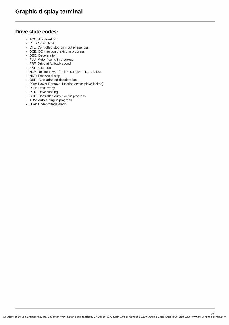
Drive state codes:- ACC: Acceleration- CLI: Current limit- CTL: Controlled stop on input phase loss- DCB: DC injection braking in progress- DEC: Deceleration- FLU: Motor fluxing in progress- FRF: Drive at fallback speed- FST: Fast stop- NLP: No line power (no line supply on L1, L2, L3)- NST: Freewheel stop- OBR: Auto-adapted deceleration- PRA: Power Removal function active (drive locked)- RDY: Drive ready- RUN: Drive running- SOC: Controlled output cut in progress- TUN: Auto-tuning in progress- USA: Undervoltage alarm
15y of Steven Engineering, Inc.-230 Ryan Way, South San Francisco, CA 94080-6370-Main Office: (650) 588-9200-Outside Local Area: (800) 258-9200-www.stevenengineering.com

Courtes
Graphic display terminal
Example configuration windows:
Example configuration window for one value:
The << and >> arrows (keys F2 and F3) are used to select the digit to be modified, and the navigation button is rotated to increase or decrease this number.
When only one possible selection can be made, the selection made is indicated by Example: Only one language can be chosen.
When multiple selection is possible, the selections made are indicated by Example: A number of parameters can be chosen to form the [USER MENU].
RDY Term +0.00 Hz REM5 LANGUAGE
EnglishFrançaisDeutschEspañolItaliano
<< >> T/KChinese
PARAMETER SELECTION1.3 SETTINGS
Ramp incrementAccelerationDecelerationAcceleration 2Deceleration 2
Edit
RDY Term +0.00 Hz REMAcceleration
9.51 sMin = 0.01 Max = 99.99
<< >> T/K
>>
RDY Term +0.00 Hz REMAcceleration
9.51 sMin = 0.01 Max = 99.99
<< >> T/K
16y of Steven Engineering, Inc.-230 Ryan Way, South San Francisco, CA 94080-6370-Main Office: (650) 588-9200-Outside Local Area: (800) 258-9200-www.stevenengineering.com

Courtes
Graphic display terminal
First power-up – [5. LANGUAGE] menuThe first time the drive is powered up, the user will automatically be guided through the menus as far as [1. DRIVE MENU].The parameters in the [1.1 SIMPLY START] submenu must be configured and auto-tuning performed before the motor is started up.
Display for 3 seconds following power-up
3 seconds
Switches to [5 LANGUAGE] menu automatically.
Select the language and press ENT.
Switches to [2 ACCESS LEVEL] menu (see page 26)Select the access level and press ENT.
Switches to [1 DRIVE MENU] (see page 22)
ESC
Press ESC to return to [MAIN MENU]
ATV61HU22N42.2kW/3HP 380/480V
Config. n°1
5 LANGUAGEEnglishFrançaisDeutschEspañolItaliano
Chinese
RDY Term +0.00 Hz REM2 ACCESS LEVEL
BasicStandardAdvancedExpert
RDY Term +0.00 Hz REM1 DRIVE MENU
1.1 SIMPLY START1.2. MONITORING1.3. SETTINGS1.4. MOTOR CONTROL1.5. INPUTS / OUTPUTS CFG
Code << >> T/K
RDY Term +0.00 Hz REMMAIN MENU
1 DRIVE MENU2 ACCESS LEVEL3 OPEN / SAVE AS4 PASSWORD5 LANGUAGE
Code T/K
17y of Steven Engineering, Inc.-230 Ryan Way, South San Francisco, CA 94080-6370-Main Office: (650) 588-9200-Outside Local Area: (800) 258-9200-www.stevenengineering.com

Courtes
Graphic display terminal
Subsequent power ups
Switches to [1. DRIVE MENU].
If no operator inputs are made, switches to “Display” automatically 10 seconds later (the display will vary depending on the selected configuration).
Users can return to [MAIN MENU] by pressing ENT or ESC.
3 seconds
10 seconds
ENT or ESC
ATV61HU22N42.2kW/3HP 380/480V
Config. n°1
RDY Term +38 Hz REM1. DRIVE MENU
1.1 SIMPLY START1.2 MONITORING1.3 SETTINGS1.4 MOTOR CONTROL1.5 INPUTS / OUTPUTS CFG
Code << >> T/K
RDY Term +38 Hz REMFrequency ref.
Min=0 Max=60T/K
RDY Term +38 Hz REMMAIN MENU
1 DRIVE MENU2 ACCESS LEVEL3 OPEN / SAVE AS4 PASSWORD5 LANGUAGE
Code T/K
38 Hz
18y of Steven Engineering, Inc.-230 Ryan Way, South San Francisco, CA 94080-6370-Main Office: (650) 588-9200-Outside Local Area: (800) 258-9200-www.stevenengineering.com
Courtes
Graphic display terminal
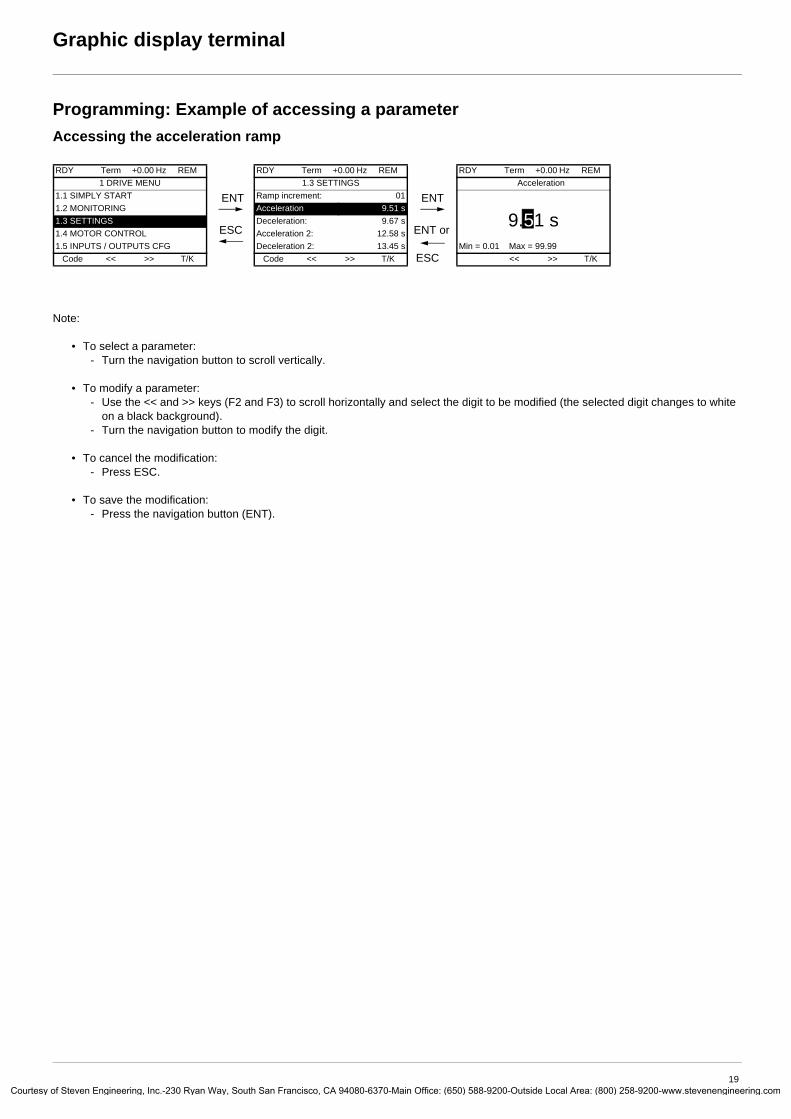
Programming: Example of accessing a parameterAccessing the acceleration ramp
Note:
• To select a parameter:- Turn the navigation button to scroll vertically.
• To modify a parameter:- Use the << and >> keys (F2 and F3) to scroll horizontally and select the digit to be modified (the selected digit changes to white
on a black background).- Turn the navigation button to modify the digit.
• To cancel the modification:- Press ESC.
• To save the modification:- Press the navigation button (ENT).
RDY Term +0.00 Hz REM1 DRIVE MENU
1.1 SIMPLY START1.2 MONITORING1.3 SETTINGS1.4 MOTOR CONTROL1.5 INPUTS / OUTPUTS CFG
Code << >> T/K
ENT
ESC
RDY Term +0.00 Hz REM1.3 SETTINGS
Ramp increment: 01Acceleration 9.51 sDeceleration: 9.67 sAcceleration 2: 12.58 sDeceleration 2: 13.45 s
Code << >> T/K
ENT
ENT or
ESC
RDY Term +0.00 Hz REMAcceleration
9.51 sMin = 0.01 Max = 99.99
<< >> T/K
19y of Steven Engineering, Inc.-230 Ryan Way, South San Francisco, CA 94080-6370-Main Office: (650) 588-9200-Outside Local Area: (800) 258-9200-www.stevenengineering.com

Courtes
Graphic display terminal
Quick navigationIn order to access this function you must first reassign the F4 key, which is assigned by default to control via the terminal (T/K) (see page 120).If the “Quick” function is displayed above the F4 key, you can gain quick access to a parameter from any screen.
Example:
Press F4 to access the Quick screen, which contains 4 selection options.
• [HOME]: Return to [MAIN MENU].
• [DIRECT ACCESS TO...]: Opens the direct access window, which will contain the text “1”. The function keys << and >> (F2 and F3) can be used to select each of the numbers and the navigation button to increment or decrement the numbers: 1.3 in the example below.
• [10 LAST MODIFICATIONS]: Opens a window in which the last 10 parameters modified can be accessed directly.
RDY Term +0.00 Hz REM1.4 MOTOR CONTROL
Standard mot. freq: 5 0 Hz IECRated motor power: 0.37 kW (0.5 HP)Rated motor volt.: 206 VRated mot. current: 1.0 ARated motor freq.: 50.0 Hz
Code << >> Quick
ENT
RDY Term +0.00 Hz REM QUICK NAVIGATION
RETURN TO MAIN MENUDIRECT ACCESS TO...10 LAST MODIFICATIONSGOTO MULTIPOINT SCREEN
Code
See page 236
RDY Term +0.00 Hz REMMAIN MENU
1 DRIVE MENU2 ACCESS LEVEL3 OPEN / SAVE AS4 PASSWORD5 LANGUAGE
Code Quick
RDY Term +0.00 Hz REMDIRECT ACCESS TO...
1.3SETTINGS
<< >>
ENT
RDY Term +0.00 Hz REM1.3 SETTINGS
Ramp increment: 01Acceleration 9.51 sDeceleration: 9.67 sAcceleration 2: 12.58 sDeceleration 2: 13.45 s
Code << >> Quick
RDY Term +0.00 Hz REM 10 LAST MODIFICATIONS
Acceleration: 10 sSpeed prop. gain: 25%Rated mot. current: 15 APreset speed 4: 20 HzPreset speed 5: 30 Hz
Code
ESC
ENT
RDY Term +0.00 Hz REM Rated mot. current
15.0 A
<< >>
20y of Steven Engineering, Inc.-230 Ryan Way, South San Francisco, CA 94080-6370-Main Office: (650) 588-9200-Outside Local Area: (800) 258-9200-www.stevenengineering.com

Courtes
Graphic display terminal
[MAIN MENU] – Menu mapping
Content of [MAIN MENU] menus
[1 DRIVE MENU] See next page
[2 ACCESS LEVEL] Defines which menus can be accessed (level of complexity)
[3 OPEN / SAVE AS] Can be used to save and recover drive configuration files
[4 PASSWORD] Provides password protection for the configuration
[5 LANGUAGE] Language selection
[6 MONITORING CONFIG.] Customization of information displayed on the graphic display terminal during operation
[7 DISPLAY CONFIG.] • Customization of parameters• Creation of a customized user menu• Customization of the visibility and protection mechanisms for menus and parameters
RDY Term +0.00 Hz REMMAIN MENU
1 DRIVE MENU2 ACCESS LEVEL3 OPEN / SAVE AS4 PASSWORD5 LANGUAGE
Code T/K6 MONITORING CONFIG.7 DISPLAY CONFIG.
RDY Term +0.00 Hz REM1 DRIVE MENU
1.1 SIMPLY START1.2 MONITORING1.3 SETTINGS1.4 MOTOR CONTROL1.5 INPUTS / OUTPUTS CFG
Code << >> T/K1.6 COMMAND1.7 APPLICATION FUNCT.1.8 FAULT MANAGEMENT1.9 COMMUNICATION1.10 DIAGNOSTICS1.11 IDENTIFICATION1.12 FACTORY SETTINGS1.13 USER MENU1.14 PROGRAMMABLE CARD
21y of Steven Engineering, Inc.-230 Ryan Way, South San Francisco, CA 94080-6370-Main Office: (650) 588-9200-Outside Local Area: (800) 258-9200-www.stevenengineering.com
Courtes
Graphic display terminal
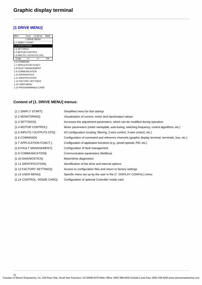
[1 DRIVE MENU]
Content of [1. DRIVE MENU] menus:
RDY Term +0.00 Hz REM1 DRIVE MENU
1.1 SIMPLY START1.2 MONITORING1.3 SETTINGS1.4 MOTOR CONTROL1.5 INPUTS / OUTPUTS CFG
Code << >> T/K1.6 COMMAND1.7 APPLICATION FUNCT.1.8 FAULT MANAGEMENT1.9 COMMUNICATION1.10 DIAGNOSTICS1.11 IDENTIFICATION1.12 FACTORY SETTINGS1.13 USER MENU1.14 PROGRAMMABLE CARD
[1.1 SIMPLY START]: Simplified menu for fast startup
[1.2 MONITORING]: Visualization of current, motor and input/output values
[1.3 SETTINGS]: Accesses the adjustment parameters, which can be modified during operation
[1.4 MOTOR CONTROL]: Motor parameters (motor nameplate, auto-tuning, switching frequency, control algorithms, etc.)
[1.5 INPUTS / OUTPUTS CFG]: I/O configuration (scaling, filtering, 2-wire control, 3-wire control, etc.)
[1.6 COMMAND]: Configuration of command and reference channels (graphic display terminal, terminals, bus, etc.)
[1.7 APPLICATION FUNCT.]: Configuration of application functions (e.g., preset speeds, PID, etc.)
[1.8 FAULT MANAGEMENT]: Configuration of fault management
[1.9 COMMUNICATION]: Communication parameters (fieldbus)
[1.10 DIAGNOSTICS]: Motor/drive diagnostics
[1.11 IDENTIFICATION]: Identification of the drive and internal options
[1.12 FACTORY SETTINGS]: Access to configuration files and return to factory settings
[1.13 USER MENU]: Specific menu set up by the user in the [7. DISPLAY CONFIG.] menu
[1.14 CONTROL. INSIDE CARD]: Configuration of optional Controller Inside card
22y of Steven Engineering, Inc.-230 Ryan Way, South San Francisco, CA 94080-6370-Main Office: (650) 588-9200-Outside Local Area: (800) 258-9200-www.stevenengineering.com

Courtes
Integrated display terminal
Low-power Altivar 61 drives (see catalog) feature an integrated display terminal with a 7-segment 4-digit display. The graphic display terminal described on the previous pages can also be connected to these drives as an option.
Functions of the display and the keys
• Pressing or does not store the selection.
• Press and hold down (>2 s) or to scroll through the data quickly.
Save and store the selection: ENT
The display flashes when a value is stored.
Normal display, with no fault present and no startup:
- 43.0: Display of the parameter selected in the SUP menu (default selection: motor frequency)- CLI: Current limit- CtL: Controlled stop on input phase loss- dCb: DC injection braking in progress- FLU: Motor fluxing in progress- FRF: Drive at fallback speed- FSt: Fast stop- nLP: No line power (no line supply on L1, L2, L3)- nSt: Freewheel stop- Obr: Auto-adapted deceleration- PrA: Power Removal function active (drive locked)- rdY: Drive ready- SOC: Controlled output cut in progress- tUn: Auto-tuning in progress- USA: Undervoltage alarm
The display flashes to indicate the presence of a fault.
• Four 7-segment displays
• Enters a menu or a parameter, or saves the displayed parameter or value
• Returns to the previous menu or parameter, or increases the displayed value
• Exits a menu or parameter, or aborts the displayed value to return to the previous value in the memory
• Goes to the next menu or parameter, or decreases the displayed value
• 2 CANopen status LEDs
• 2 Modbus status LEDs
Note:
23y of Steven Engineering, Inc.-230 Ryan Way, South San Francisco, CA 94080-6370-Main Office: (650) 588-9200-Outside Local Area: (800) 258-9200-www.stevenengineering.com

Courtes
Integrated display terminal
Accessing menus
A dash appears after menu and submenu codes to differentiate them from parameter codes. Examples: FUn- menu, ACC parameter.
The grayed-out menus may not be accessible depending on the control access (LAC) configuration.
XXX
CtL-
FUn-
SIM-
I-O-
SEt-
SUP-
ESC
ESC
ESC
ESC
ESC
ESC
ESC
ESC
ENT
ENT
ESC
ENT
ESC
ENT
ESC
ENT
ESC
ENT
ESC
ENT
ESC
ENT
ESC
FCS-
LAC-
CON-
FLt-
ESC
ESC
ESC
ESCENT
ESC
ENT
ESC
ENT
ESC
ENT
ESC
ENT
ESC
SPL-
ESCENT
ESC
drC-
COd-
USr-
ESCENT
ESC
Displays the drive state
SETTINGS
APPLICATION FUNCT.
INPUTS / OUTPUTS CFG
FAULT MANAGEMENT
SIMPLY START
Menus
MONITORING
MOTOR CONTROL
COMMAND
Power-up
FACTORY SETTINGS
PASSWORD
ACCESS LEVEL
COMMUNICATION
(page 47) Adjustment parameters, can be modified during operation
(page 121) Configuration of application functions (e.g., preset speeds, PID, etc.)
(page 79) I/O configuration (scaling, filtering, 2-wire control,3-wire control, etc.)
(page 185) Configuration of fault management
(page 32) Simplified menu for fast startup
(page 38) Visualization of current, motor and input/output values
(page 66) Motor parameters (motor nameplate, auto-tuning, switching frequency, control algorithms, etc.)
(page 108) Configuration of command and reference channels (graphic display terminal, terminals, bus, etc.)
(page 218) Access to configuration files and return to factorysettings
(page 225)
(page 26)
(page 211) Communication parameters (fieldbus)
(page 221) Specific menu, set up by the user using the graphic display terminal.USER MENU
PROGRAMMABLE CARD(page 222) Menu for the Controller Inside card, if present.
24y of Steven Engineering, Inc.-230 Ryan Way, South San Francisco, CA 94080-6370-Main Office: (650) 588-9200-Outside Local Area: (800) 258-9200-www.stevenengineering.com

Courtes
Integrated display terminal
Accessing menu parametersSave and store the displayed selection:
The display flashes when a value is stored.
All the menus are “drop-down scrolling” menus, which means that after the last parameter, if you continue to press , you will return to the first parameter and, conversely, you can switch from the first parameter to the last parameter by pressing .
Selection of multiple assignments for one parameterExample: List of group 1 alarms in [INPUTS / OUTPUTS CFG]menu (I-O-)A number of alarms can be selected by “checking” them as follows.
The digit on the right indicates: selected not selected The same principle is used for all multiple selections.
ENT
��� ����
���
���
���
���
���� ����
���
�����
��
Menu Value or assignment
1 flash (save)
Parameter
(Next parameter)
���
���
1st
nth
last
Menu
ENT
ESC
I-O-
Alarm not selected
Alarm selected
25y of Steven Engineering, Inc.-230 Ryan Way, South San Francisco, CA 94080-6370-Main Office: (650) 588-9200-Outside Local Area: (800) 258-9200-www.stevenengineering.com

Courtes
[2. ACCESS LEVEL] (LAC-)
With graphic display terminalBasicAccess to 5 menus only, and access to 6 submenus only in the [1. DRIVE MENU] menu. A single function can be assigned to each input.
StandardThis is the factory-set level. Access to 6 menus only, and access to all submenus in the [1. DRIVE MENU] menu.A single function can be assigned to each input.
AdvancedAccess to all menus and submenus.Several functions can be assigned to each input.
ExpertAccess to all menus and submenus as for [Advanced] level, and access to additional parameters.Several functions can be assigned to each input.
RDY Term +0.00 Hz REM2 ACCESS LEVEL
BasicStandardAdvancedExpert
<< >> T/K
RDY Term +0.00 Hz REMMAIN MENU
1 DRIVE MENU2 ACCESS LEVEL3 OPEN / SAVE AS4 PASSWORD5 LANGUAGE
Code << >> T/K
RDY Term +0.00 Hz REM1. DRIVE MENU
1.1 SIMPLY START1.2. MONITORING1.3. SETTINGS1.11. IDENTIFICATION1.12. FACTORY SETTINGS
Code << >> T/K1.13 USER MENU
RDY Term +0.00 Hz REM
MAIN MENU1 DRIVE MENU2 ACCESS LEVEL3 OPEN / SAVE AS4 PASSWORD5 LANGUAGE
Code T/K6 MONITORING CONFIG.
RDY Term +0.00 Hz REM1 DRIVE MENU
1.1 SIMPLY START1.2 MONITORING1.3 SETTINGS1.4 MOTOR CONTROL1.5 INPUTS / OUTPUTS CFG
Code << >> T/K1.6 COMMAND1.7 APPLICATION FUNCT.1.8 FAULT MANAGEMENT1.9 COMMUNICATION1.10 DIAGNOSTICS1.11 IDENTIFICATION1.12 FACTORY SETTINGS1.13 USER MENU1.14 PROGRAMMABLE CARDRDY Term +0.00 Hz REM
MAIN MENU1 DRIVE MENU2 ACCESS LEVEL3 OPEN / SAVE AS4 PASSWORD5 LANGUAGE
Code T/K6 MONITORING CONFIG.7 DISPLAY CONFIG.
RDY Term +0.00 Hz REMMAIN MENU
1 DRIVE MENU2 ACCESS LEVEL3 OPEN / SAVE AS4 PASSWORD5 LANGUAGE
Code T/K6 MONITORING CONFIG.7 DISPLAY CONFIG.
26y of Steven Engineering, Inc.-230 Ryan Way, South San Francisco, CA 94080-6370-Main Office: (650) 588-9200-Outside Local Area: (800) 258-9200-www.stevenengineering.com

Courtes
[2. ACCESS LEVEL] (LAC-)
With integrated display terminal:
Code Name/Description Factory setting
LAC- Std
bAS
Std
Adu
Epr
• bAS: Limited access to SIM, SUP, SEt, FCS, USr, COd and LAC menus. A single function can be assigned to each input.
• Std: Access to all menus on the integrated display terminal. A single function can be assigned to each input.• AdU: Access to all menus on the integrated display terminal. Several functions can be assigned to each input.• EPr: Access to all menus on the integrated display terminal and access to additional parameters. Several functions
can be assigned to each input.
XXX
SIM-
ESC
ESC
ENT
LAC-
ESC
ENT
ESC
COd-
Displays the drive state
ACCESS LEVEL
Power-up
27y of Steven Engineering, Inc.-230 Ryan Way, South San Francisco, CA 94080-6370-Main Office: (650) 588-9200-Outside Local Area: (800) 258-9200-www.stevenengineering.com

Courtes
[2. ACCESS LEVEL] (LAC-)
Comparison of the menus that can be accessed on the graphic display terminal/integrated display terminal
(1)Can be accessed if the Controller Inside card is present.
Graphic display terminal Integrated display terminal Access level
[2 ACCESS LEVEL] LAC- (Access level)
Bas
ic b
AS
Sta
ndar
d Std�(fa
ctor
y se
tting
)
Adv
ance
d AdU
Exp
ert E
Pr
[3. OPEN / SAVE AS] -
[4 PASSWORD] COd- (Password)
[5 LANGUAGE] -
[1 DRIVE MENU] [1.1 SIMPLY START] SIM- (Simply start)
[1.2 MONITORING] SUP-�(Monitoring)
[1.3 SETTINGS] SEt- (Settings)
[1.11 IDENTIFICATION] -
[1.12 FACTORY SETTINGS] FCS- (Factory settings)
[1.13 USER MENU] USr- (User menu)
A single function can be assigned to each input. A single function can be assigned to each input.
[1.4 MOTOR CONTROL] drC- (Motor control)
[1.5 INPUTS / OUTPUTS CFG] I-O- (I/O configuration)
[1.6 COMMAND] CtL- (Command)
[1.7 APPLICATION FUNCT.] FUn- (Application functions)
[1.8 FAULT MANAGEMENT] FLt- (Fault management)
[1.9 COMMUNICATION] COM- (Communication)
[1.10 DIAGNOSTICS] -
[1.14 PROGRAMMABLE CARD] (1) PLC- (Controller Inside card) (1)
[6 MONITORING CONFIG.] -
A single function can be assigned to each input. A single function can be assigned to each input.
[7 DISPLAY CONFIG.] -
Several functions can be assigned to each input. Several functions can be assigned to each input.
Expert parameters Expert parameters
Several functions can be assigned to each input. Several functions can be assigned to each input.
28y of Steven Engineering, Inc.-230 Ryan Way, South San Francisco, CA 94080-6370-Main Office: (650) 588-9200-Outside Local Area: (800) 258-9200-www.stevenengineering.com

Courtes
Structure of parameter tables
The parameter tables in the descriptions of the various menus can be used with both the graphic display terminal and the integrated display terminal. They, therefore, contain information for these two terminals in accordance with the description below.
Example:
[1.7 APPLICATION FUNCT.] (FUn-)
Code Name/Description Adjustment range Factory setting
UPd- b [+/- SPEED]Function can be accessed for reference channel [Ref.2 channel] (Fr2) = [+/- speed] (UPdt), see page 118
USP M [+ speed assignment] [No] (nO)
no
LII
v [No] (nO): Function inactivev [LI1] (LI1)
Note: • The text in square brackets [ ] indicates what you will see on the graphic display terminal.• The factory settings correspond to [Macro configuration] (CFG) = [Pumps.Fans] (PnF). This is the macro configuration
set at the factory.
5
2
3
1
4
6
8
7
1. Name of menu on 4-digit 7-segment display
2. Submenu code on 4-digit 7-segment display
3. Parameter code on 4-digit 7-segment display
4. Parameter value on 4-digit 7-segment display
5. Name of menu on graphic display terminal
6. Name of submenu on graphic display terminal
7. Name of parameter on graphic display terminal
8. Value of parameter on graphic display terminal
29y of Steven Engineering, Inc.-230 Ryan Way, South San Francisco, CA 94080-6370-Main Office: (650) 588-9200-Outside Local Area: (800) 258-9200-www.stevenengineering.com

Courtes
Interdependence of parameter values
The configuration of certain parameters modifies the adjustment range of other parameters, in order to reduce the risk of errors. This may result in the modification of a factory setting or a value you have already selected.
Example 1:1. [Switching freq.] (SFr) page 75 set to 16 kHz.2. [Sinus filter] (OFI), see page 75, set to [Yes] (YES) (and confirmed with “ENT”) limits [Switching freq.] (SFr) to 8 kHz.If you set [Sinus filter] (OFI) to [No] (nO), [Switching freq.] (SFr) will no longer be limited but will remain at 8 kHz. If you require 16 kHz, you must reset [Switching freq.] (SFr).
Example 2:1. The factory setting of [Switching freq.] (SFr) page 75 remains unchanged at 2.5 kHz.2. Setting [Sinus filter] (OFI) page 75 to [Yes] (YES) (and confirming with “ENT”) changes the factory setting of [Switching freq.]
(SFr) to 4 kHz.3. If you set [Sinus filter] (OFI) to [No] (nO), [Switching freq.] (SFr) will remain at 4 kHz. If you require 2.5 kHz, you must reset
[Switching freq.] (SFr).
30y of Steven Engineering, Inc.-230 Ryan Way, South San Francisco, CA 94080-6370-Main Office: (650) 588-9200-Outside Local Area: (800) 258-9200-www.stevenengineering.com

Courtes
Finding a parameter in this document
The following assistance with finding explanations on a parameter is provided:
• With the integrated display terminal: Direct use of the parameter code index, page 247, to find the page giving details of the displayed parameter.
• With the graphic display terminal: Select the required parameter and press : [Code]. The parameter code is displayed instead of its name while the key is held down. Example: ACC
Then use the parameter code index, page 247, to find the page giving details of the displayed parameter.
F1
RDY Term +0.00 Hz REM1.3 SETTINGS
Ramp increment: 01Acceleration 9.51 sDeceleration: 9.67 sAcceleration 2: 12.58 sDeceleration 2: 13.45 s
Code << >> T/K
Code
RDY Term +0.00 Hz REM1.3 SETTINGS
Ramp increment: 01ACC 9.51 sDeceleration: 9.67 sAcceleration 2: 12.58 sDeceleration 2: 13.45 s
Code << >> T/K
31y of Steven Engineering, Inc.-230 Ryan Way, South San Francisco, CA 94080-6370-Main Office: (650) 588-9200-Outside Local Area: (800) 258-9200-www.stevenengineering.com

Courtes
[1.1 SIMPLY START] (SIM-)
With graphic display terminal:
With integrated display terminal:
The [1.1-SIMPLY START] (SIM-) menu can be used for fast startup, which is sufficient for the majority of applications.
The parameters in this menu can only be modified when the drive is stopped and no run command is present, with the following exceptions:• Auto-tuning, which causes the motor to start up• The adjustment parameters on page 37
The [1.1 SIMPLY START] (SIM-) menu should be configured on its own or before the other drive configuration menus. If a modification has previously been made to any of them, in particular in [1.4 MOTOR CONTROL] (drC-), some [1.1 SIMPLY START] (SIM-) parameters may be changed, for example, the motor parameters, if a synchronous motor has been selected. Returning to the [1.1 SIMPLY START](SIM-) menu after modifying another drive configuration menu is unnecessary but does not pose any risk. Changes following modification of another configuration menu are not described, to avoid unnecessary complication in this section.
Macro configurationMacro configuration provides a means of speeding up the configuration of functions for a specific field of application.5 macro configurations are available:
• Start/stop• General use• PID regulator• Communication bus• Pumps/fans (factory configuration)
Selecting a macro configuration assigns the parameters in this macro configuration.
Each macro configuration can still be modified in the other menus.
Note: The parameters of the [1.1 SIMPLY START] (SIM-) menu must be entered in the order in which they appear, as the later ones are dependent on the first ones.For example [2/3 wire control] (tCC) must be configured before any other parameters.
RDY Term +0.00 Hz REMMAIN MENU
1 DRIVE MENU2 ACCESS LEVEL3 OPEN / SAVE AS4 PASSWORD5 LANGUAGE
Code T/K
ENTRDY Term +0.00 Hz REM
1 DRIVE MENU1.1 SIMPLY START1.2 MONITORING1.3 SETTINGS1.4 MOTOR CONTROL1.5 INPUTS / OUTPUTS CFG
Code << >> T/K
ENTRUN Term +0.00 Hz REM
1.1 SIMPLY START2/3 wire controlMacro configurationCustomized macroStandard mot. freqInput phase loss
Code << >> T/K
XXX
SIM-
SUP-
ESC
ESC
ESC
ENT
ENT
ESC
LAC-
Displays the drive state
SIMPLY START
Power-up
32y of Steven Engineering, Inc.-230 Ryan Way, South San Francisco, CA 94080-6370-Main Office: (650) 588-9200-Outside Local Area: (800) 258-9200-www.stevenengineering.com

Courtes
[1.1 SIMPLY START] (SIM-)
Macro configuration parametersAssignment of the inputs/outputs
(1) To start up with integrated Modbus, [Modbus Address] (Add) must first be configured, page 213.
Note: These assignments are reinitialized every time the macro configuration changes.
Return to factory settings:Returning to factory settings with [Config. source] (FCSI) = [Macro-Conf] (InI) page 220 will restore the selected macro configuration. The [Macro configuration] (CFG) parameter does not change, although [Customized macro] (CCFG) disappears.
Input/ output
[Start/Stop] [Gen. Use] [PID regul.] [Network C.] [Pumps.Fans]
AI1 [Ref.1 channel] [Ref.1 channel] [Ref.1 channel] (PID reference)
[Ref.2 channel] ([Ref.1 channel] = integrated Modbus) (1)
[Ref.1 channel]
AI2 [No] [Summing ref. 2] [PID feedback] [No] [Ref.1B channel]AO1 [No] [No] [No] [No] [No]R1 [No drive flt] [No drive flt] [No drive flt] [No drive flt] [No drive flt]R2 [No] [No] [No] [No] [Drv running]LI1 (2-wire) [Forward] [Forward] [Forward] [Forward] [Forward]LI2 (2-wire) [Fault reset] [Reverse] [Fault reset] [Fault reset] [No]LI3 (2-wire) [No] [Jog] [PID integral reset] [Ref. 2 switching] [Ref 1B switching]LI4 (2-wire) [No] [Fault reset] [2 preset PID ref.] [Forced local] [Fault reset]LI5 (2-wire) [No] [Torque limitation] [4 preset PID ref.] [No] [No]LI6 (2-wire) [No] [No] [No] [No] [No]LI1 (3-wire) Stop Stop Stop Stop StopLI2 (3-wire) [Forward] [Forward] [Forward] [Forward] [Forward]LI3 (3-wire) [Fault reset] [Reverse] [Fault reset] [Fault reset] [No]LI4 (3-wire) [No] [Jog] [PID integral reset] [Ref. 2 switching] [Ref 1B switching]LI5 (3-wire) [No] [Fault reset] [2 preset PID ref.] [Forced local] [Fault reset]LI6 (3-wire) [No] [Torque limitation] [4 preset PID ref.] [No] [No]
Option cards
LI7 to LI14 [No] [No] [No] [No] [No]LO1 to LO4 [No] [No] [No] [No] [No]R3/R4 [No] [No] [No] [No] [No]AI3, AI4 [No] [No] [No] [No] [No]RP [No] [No] [No] [No] [No]AO2 [I motor] [I motor] [I motor] [I motor] [I motor]AO3 [No] [No] [PID Output] [No] [No]
Graphic display terminal keys
F1 key [No] [No] [No] [No] [No]F2, F3 keys [No] [No] [No] [No] [No]F4 key [T/K]
(Control via graphic display terminal)
[T/K](Control via graphic display terminal)
[T/K](Control via graphic display terminal)
[T/K](Control via graphic display terminal)
[T/K](Control via graphic display terminal)
In 3-wire control, the assignment of inputs LI1 to LI7 shifts.
Note: • The factory settings in the parameter tables correspond to [Macro configuration] (CFG) = [Pumps.Fans] (PnF). This is the
macro configuration set at the factory.
33y of Steven Engineering, Inc.-230 Ryan Way, South San Francisco, CA 94080-6370-Main Office: (650) 588-9200-Outside Local Area: (800) 258-9200-www.stevenengineering.com

Courtes
[1.1 SIMPLY START] (SIM-)
Code Name/Description Adjustment range Factory setting
tCC M [2/3 wire control] [2 wire] (2C)
2C
3C
v [2 wire] (2C) v [3 wire] (3C)
2-wire control: This is the input state (0 or 1) or edge (0 to 1 or 1 to 0), which controls running or stopping.
Example of “source” wiring: LI1: forward LIx: reverse
3-wire control (pulse control): A “forward” or “reverse” pulse is sufficient to command starting, a “stop” pulse is sufficient to command stopping. Example of “source” wiring:
LI1: stop LI2: forward LIx: reverse
CFG M [Macro configuration] [Pumps.Fans] (PnF)
StS
GEn
PId
nEt
PnF
v [Start/Stop] (StS): Start/stopv [Gen. Use] (GEn): General usev [PID regul.] (PId): PID regulationv [Network C.] (nEt): Communication busv [Pumps.Fans] (PnF): Pumps/fans
CCFG M [Customized macro]
YES
Read-only parameter, only visible if at least one macro configuration parameter has been modified.v [Yes] (YES)
+24 LI1 LIxATV 71
+24 LI1 LI2 LIxATV 71
WARNINGUNINTENDED EQUIPMENT OPERATIONTo change the assignment of [2/3 wire control] (tCC) press the “ENT” key for 2 s.The following function will be returned to factory settings: [2 wire type] (tCt) page 80 as will all functions which assign logic inputs. The macro configuration selected will also be reset if it has been customized (loss of custom settings). Check that this change is compatible with the wiring diagram used.Failure to follow these instructions can result in death or serious injury.
WARNINGUNINTENDED EQUIPMENT OPERATIONTo change the assignment of [Macro configuration] (CFG) press the “ENT” key for 2 s.Check that the selected macro configuration is compatible with the wiring diagram used.Failure to follow these instructions can result in death or serious injury.
34y of Steven Engineering, Inc.-230 Ryan Way, South San Francisco, CA 94080-6370-Main Office: (650) 588-9200-Outside Local Area: (800) 258-9200-www.stevenengineering.com

Courtes
[1.1 SIMPLY START] (SIM-)
(1) In corresponds to the rated drive current indicated in the Installation Manual and on the drive nameplate.
Code Name/Description Adjustment range Factory setting
bFr M [Standard mot. freq] [50Hz IEC] (50)
50
60
v [50Hz IEC] (50): IEC.v [60Hz NEMA] (60): NEMA.
This parameter modifies the presets of the following parameters: [Rated motor power] (nPr), [Rated motor volt.] (UnS), [Rated drive current] (nCr), [Rated motor freq.] (FrS), [Rated motor speed] (nSP), and [Max frequency] (tFr) below, [Mot. therm. current] (ItH) page 37, [High speed] (HSP) page 37.
IPL� M [Input phase loss] According to drive rating
nO
YES
v [Ignore] (nO): Fault ignored, to be used when the drive is supplied via a single-phase supply or by the DC bus.v [Freewheel] (YES): Fault, with freewheel stop.
If one phase disappears, the drive switches to fault mode [Input phase loss] (IPL) but if 2 or 3 phases disappear, the drive continues to operate until it trips on an undervoltage fault. This parameter is only accessible in this menu on ATV61H037M3 to HU75M3 drives (used with a single phase supply).
nPr M [Rated motor power] According to drive rating
According to drive rating
Rated motor power given on the nameplate, in kW if [Standard mot. freq] (bFr) = [50 Hz IEC] (50), in HP if [Standard mot. freq] (bFr) = [60 Hz NEMA] (60).
UnS M [Rated motor volt.] According to drive rating
According to drive rating and [Standard mot. freq] (bFr)
Rated motor voltage given on the nameplate.ATV61pppM3: 100 to 240 V - ATV61pppN4: 200 to 480 V - ATV61pppY: 400 to 690 V.
nCr M [Rated mot. current] 0.25 to 1.1 or 1.2 Hz according to rating (1)
According to drive rating and [Standard mot. freq] (bFr)
Rated motor current given on the nameplate.
FrS M [Rated motor freq.] 10 to 500 or 1,000 Hz according to rating
50 Hz
Rated motor frequency given on the nameplate.The factory setting is 50 Hz, or preset to 60 Hz if [Standard mot. freq] (bFr) is set to 60 Hz.
nSP M [Rated motor speed] 0 to 60,000 rpm According to drive rating
Rated motor speed given on the nameplate.0 to 9,999 rpm then 10.00 to 60.00 krpm on the integrated display terminal.If, rather than the rated speed, the nameplate indicates the synchronous speed and the slip in Hz or as a %, calculate the rated speed as follows:
• Nominal speed = Synchronous speed x or
• Nominal speed = Synchronous speed x (50 Hz motors) or
• Nominal speed = Synchronous speed x (60 Hz motors)
tFr M [Max frequency] 10 to 500 or 1,000 Hz according to rating
60 Hz
The factory setting is 60 Hz, or preset to 72 Hz if [Standard mot. freq] (bFr) is set to 60 Hz.The maximum value is limited by the following conditions:• It must not exceed 10 times the value of [Rated motor freq.] (FrS)• Values between 500 Hz and 1000 Hz are not possible for ATV61HpppY (500 to 690 V)• Values between 500 Hz and 1,000 Hz are only possible in V/F control and for powers limited to 37 kW
(50 HP) for ATV61H ppp and 45 kW (60 HP) for ATV61Wppp. In this case, configure [Motor control type] (Ctt) before [Max frequency] (tFr).
100 - slip as a %100
50 - slip in Hz50
60 - slip in Hz60
35y of Steven Engineering, Inc.-230 Ryan Way, South San Francisco, CA 94080-6370-Main Office: (650) 588-9200-Outside Local Area: (800) 258-9200-www.stevenengineering.com
Courtes
[1.1 SIMPLY START] (SIM-)
Code Name/Description Factory setting
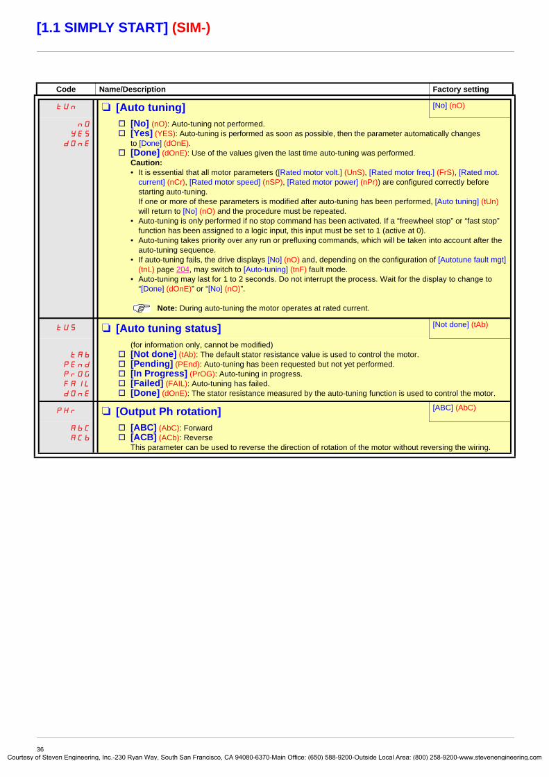
tUn M [Auto tuning] [No] (nO)
nO
YES
dOnE
v [No] (nO): Auto-tuning not performed.v [Yes] (YES): Auto-tuning is performed as soon as possible, then the parameter automatically changes
to [Done] (dOnE).v [Done] (dOnE): Use of the values given the last time auto-tuning was performed.
Caution: • It is essential that all motor parameters ([Rated motor volt.] (UnS), [Rated motor freq.] (FrS), [Rated mot.
current] (nCr), [Rated motor speed] (nSP), [Rated motor power] (nPr)) are configured correctly before starting auto-tuning. If one or more of these parameters is modified after auto-tuning has been performed, [Auto tuning] (tUn) will return to [No] (nO) and the procedure must be repeated.
• Auto-tuning is only performed if no stop command has been activated. If a “freewheel stop” or “fast stop” function has been assigned to a logic input, this input must be set to 1 (active at 0).
• Auto-tuning takes priority over any run or prefluxing commands, which will be taken into account after the auto-tuning sequence.
• If auto-tuning fails, the drive displays [No] (nO) and, depending on the configuration of [Autotune fault mgt] (tnL) page 204, may switch to [Auto-tuning] (tnF) fault mode.
• Auto-tuning may last for 1 to 2 seconds. Do not interrupt the process. Wait for the display to change to “[Done] (dOnE)” or “[No] (nO)”.
Note: During auto-tuning the motor operates at rated current.
tUS M [Auto tuning status] [Not done] (tAb)
tAb
PEnd
PrOG
FAIL
dOnE
(for information only, cannot be modified)v [Not done] (tAb): The default stator resistance value is used to control the motor.v [Pending] (PEnd): Auto-tuning has been requested but not yet performed.v [In Progress] (PrOG): Auto-tuning in progress.v [Failed] (FAIL): Auto-tuning has failed.v [Done] (dOnE): The stator resistance measured by the auto-tuning function is used to control the motor.
PHr M [Output Ph rotation] [ABC] (AbC)
AbC
ACb
v [ABC] (AbC): Forwardv [ACB] (ACb): Reverse
This parameter can be used to reverse the direction of rotation of the motor without reversing the wiring.
36y of Steven Engineering, Inc.-230 Ryan Way, South San Francisco, CA 94080-6370-Main Office: (650) 588-9200-Outside Local Area: (800) 258-9200-www.stevenengineering.com

Courtes
[1.1 SIMPLY START] (SIM-)
Parameters that can be changed during operation or when stopped
(1) In corresponds to the rated drive current indicated in the Installation Manual and on the drive nameplate.
Code Name/Description Factory setting
ItH M [Mot. therm. current] 0 to 1.1 or 1.2 In (1) according to rating
According to drive rating
Motor thermal protection current, to be set to the rated current indicated on the nameplate.
ACC M [Acceleration] 0.1 to 999.9 s 3.0 s
Time to accelerate from 0 to the [Rated motor freq.] (FrS) (page 35). Make sure that this value is compatible with the inertia being driven.
dEC M [Deceleration] 0.1 to 999.9 s 3.0 s
Time to decelerate from the [Rated motor freq.] (FrS) (page 35) to 0. Make sure that this value is compatible with the inertia being driven.
LSP M [Low speed] 0
Motor frequency at minimum reference, can be set between 0 and [High speed] (HSP).
HSP M [High speed] 50 Hz
Motor frequency at maximum reference, can be set between [Low speed] (LSP) and [Max frequency] (tFr). The factory setting changes to 60 Hz if [Standard mot. freq] (bFr) = [60Hz NEMA] (60).
37y of Steven Engineering, Inc.-230 Ryan Way, South San Francisco, CA 94080-6370-Main Office: (650) 588-9200-Outside Local Area: (800) 258-9200-www.stevenengineering.com

Courtes
[1.2 MONITORING] (SUP-)
With graphic display terminal:
With integrated display terminal:
RDY Term +0.00 Hz REMMAIN MENU
1 DRIVE MENU2 ACCESS LEVEL3 OPEN / SAVE AS4 PASSWORD5 LANGUAGE
Code T/K
ENT
RDY Term +0.00 Hz REM1 DRIVE MENU
1.1 SIMPLY START1.2 MONITORING1.3 SETTINGS1.4 MOTOR CONTROL1.5 INPUTS / OUTPUTS CFG
Code << >> T/K
ENTRUN Term +0.00 Hz REM
1.2 MONITORINGI/O MAPPROG. CARD I/O MAPCOMMUNICATION MAPAlarm groups :HMI Frequency ref. :
Code << >> T/K
XXX
SIM-
SEt-
SUP-
ESC
ESC
ESC
ESC
ENT
ENT
ESC
LAC-
Displays the drive state
MONITORING
Power-up
38y of Steven Engineering, Inc.-230 Ryan Way, South San Francisco, CA 94080-6370-Main Office: (650) 588-9200-Outside Local Area: (800) 258-9200-www.stevenengineering.com

Courtes
[1.2 MONITORING] (SUP-)
With graphic display terminalThis menu can be used to display the inputs/outputs, the drive internal states and values, and the communication data and values.
I/O
RUN Term +50.00 Hz REM1.2 MONITORING
I/O MAPPROG. CARD I/O MAPCOMMUNICATION MAPAlarm groups:HMI Frequency ref.:
Code << >> T/K
RUN Term +50.00 Hz REM Move from one screen to another (from LOGIC INPUT MAP to FREQ. SIGNAL IMAGE) by turning the navigation button
I/O MAPLOGIC INPUT MAPANALOG INPUTS IMAGELOGIC OUTPUT MAPANALOG OUTPUTS IMAGEFREQ. SIGNAL IMAGE
Code T/K
State 0
State 1
RUN Term-{}- +50.00 Hz REM Access to the selected input or output configuration: Press ENT.
RUN Term +50.00 Hz REMLOGIC INPUT MAP LI1 assignment
PR LI1 LI2 LI3 LI4 LI5 LI6 LI7 ForwardPre Fluxing
LI8 LI9 LI10 LI11 LI12 LI13 LI14 LI1 On Delay : 0 ms
<< >> T/K << >> T/K
RUN Term +50.00 Hz REM RUN Term +50.00 Hz REMANALOG INPUTS IMAGE AI1 assignment
AI1 : 9.87 V Ref.1 channelAI2 : 2.35 mA Forced local
Torque referenceAI1 min value : 0.0 VAI1 max value : 10.0 V
Code << >> T/K T/K
State 0
State 1
RUN Term +50.00 Hz REM RUN Term +50.00 Hz REMLOGIC OUTPUT MAP LO1 assignment
R1 R2 LO NoLO1 delay time : 0 msLO1 active at : 1
LOA: 0000000000000010b LO1 holding time : 0 ms
<< >> T/K << >> T/K
RUN Term +50.00 Hz REM RUN Term +50.00 Hz REMANALOG OUTPUTS IMAGE AO1 assignment
AO1 : 9.87 V Motor freq.AO1 min output : 4 mAAO1 max output : 20 mAAO1 Filter : 10 ms
Code << >> T/K T/K
RUN Term +50.00 Hz REM RUN Term +50.00 Hz REMFREQ. SIGNAL IMAGE RP assignment
RP input : 25.45 kHz Frequency ref. Encoder : 225 kHz RP min value : 2 kHz
RP max value : 50 kHzRP filter : 0 ms
Code << >> T/K T/K
I/OI/O of the Controller Inside card if it is presentCommunication data and values
Drive internal drive states and values (see page 44)
ENT
ENT
ENT
ENT
10
10
39y of Steven Engineering, Inc.-230 Ryan Way, South San Francisco, CA 94080-6370-Main Office: (650) 588-9200-Outside Local Area: (800) 258-9200-www.stevenengineering.com
Courtes
[1.2 MONITORING] (SUP-)
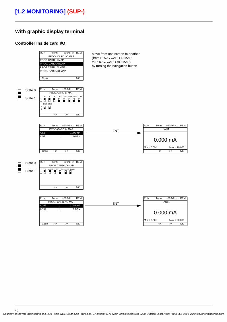
With graphic display terminal
Controller Inside card I/O
RUN Term +50.00 Hz REM Move from one screen to another (from PROG CARD LI MAP to PROG. CARD AO MAP) by turning the navigation button
PROG. CARD I/O MAPPROG CARD LI MAPPROG. CARD AI MAPPROG CARD LO MAPPROG. CARD AO MAP
Code T/K
State 0
State 1
RUN Term +50.00 Hz REM PROG CARD LI MAP
LI51 LI52 LI53 LI54 LI55 LI56 LI57 LI58
LI59 LI60
<< >> T/K
RUN Term +50.00 Hz REM RUN Term +50.00 Hz REMPROG CARD AI MAP AI51
AI51 : 0.000 mAAI52 : 9.87 V
0.000 mAMin = 0.001 Max = 20.000
Code << >> T/K << >> T/K
State 0
State 1
RUN Term +50.00 Hz REMPROG CARD LO MAP
LO51 LO52 LO53 LO54 LO55 LO56
<< >> T/K
RUN Term +50.00 Hz REM RUN Term +50.00 Hz REMPROG. CARD AO MAP AO51
AO51 : 0.000 mAAO52 : 9.87 V
0.000 mAMin = 0.001 Max = 20.000
Code << >> T/K << >> T/K
ENT
ENT
10
10
10
40y of Steven Engineering, Inc.-230 Ryan Way, South San Francisco, CA 94080-6370-Main Office: (650) 588-9200-Outside Local Area: (800) 258-9200-www.stevenengineering.com

Courtes
[1.2 MONITORING] (SUP-)
With graphic display terminalCommunication
[COM. SCANNER INPUT MAP] and [COM SCAN OUTPUT MAP]:Visualization of registers exchanged periodically (8 input and 8 output) for integrated Modbus and for fieldbus cards.
[COMMUNICATION MAP] indicates the types of bus used for control or reference, the corresponding command and reference values, the status word, the words selected in the [DISPLAY CONFIG] menu, etc.The display format (hexadecimal or decimal) can be configured in the [DISPLAY CONFIG.] menu.
RUN Term +50.00 Hz REMCOMMUNICATION MAP
Command Channel: ModbusCmd value: ABCD HexActive ref. channel: CANopenFrequency ref.: - 12.5 HzETA status word: 2153 Hex
Code T/KW3141: F230 HexW2050: F230 HexW4325: F230 HexW0894: F230 HexCOM. SCANNER INPUT MAPCOM SCAN OUTPUT MAPCMD. WORD IMAGEFREQ. REF. WORD MAPMODBUS NETWORK DIAGMODBUS HMI DIAGCANopen MAPPROG. CARD SCANNER
RUN Term +50.00 Hz REM
COM. SCANNER INPUT MAPCom Scan In1 val.: 0Com Scan In2 val.: 0Com Scan In3 val.: 0Com Scan In4 val.: 0Com Scan In5 val.: 0
Code T/KCom Scan In6 val.: 0Com Scan In7 val.: 0Com Scan In8 val.: 0
RUN Term +50.00 Hz REMCOM SCAN OUTPUT MAP
Com Scan Out1 val.: 0Com Scan Out2 val.: 0Com Scan Out3 val.: 0Com Scan Out4 val.: 0Com Scan Out5 val.: 0
Code T/KCom Scan Out6 val.: 0Com Scan Out7 val.: 0Com Scan Out8 val.: 0
RUN Term +50.00 Hz REMCMD. WORD IMAGE
Modbus cmd.: 0000 Hex.CANopen cmd.: 0000 Hex.COM. card cmd.: 0000 Hex.Prog. card cmd: 0000 Hex.
Code T/KRUN Term +50.00 Hz REM
FREQ. REF. WORD MAPModbus ref.: 0.0 HzCANopen ref.: 0.0 HzRef. Com. card: 0.0 HzProg. Card ref: 0.0 Hz
Code T/K
41y of Steven Engineering, Inc.-230 Ryan Way, South San Francisco, CA 94080-6370-Main Office: (650) 588-9200-Outside Local Area: (800) 258-9200-www.stevenengineering.com

Courtes
[1.2 MONITORING] (SUP-)
With graphic display terminalCommunication (continued)
The state of the LEDs, the periodic data, the address, the speed, and the format, etc,. is given for each bus.
LED offLED on
RUN Term +50.00 Hz REMCOMMUNICATION MAP
Command Channel: ModbusCmd value: ABCD HexActive ref. channel: CANopenFrequency ref.: - 12.5 HzETA status word: 2153 Hex
Code T/KW3141 : F230 HexW2050 : F230 HexW4325 : F230 HexW0894 : F230 HexCOM. SCANNER INPUT MAPCOM SCAN OUTPUT MAPCMD. WORD IMAGEFREQ. REF. WORD MAPMODBUS NETWORK DIAGMODBUS HMI DIAGCANopen MAPPROG. CARD SCANNER
Communication via Modbus RUN Term +50.00 Hz REM
MODBUS NETWORK DIAGCOM LED : Mb NET frames nb.Mb NET CRC errors
Code T/K
Communication via the graphic display terminal RUN Term +50.00 Hz REM
MODBUS HMI DIAGCOM LED : Mb HMI frames nb.Mb HMI CRC errors
Code T/KPDO configuration using the network tool.Some PDOs cannot be used.RUN Term +50.00 Hz REM
PDO1 IMAGEReceived PDO1-1 : FDBA HexReceived PDO1-2Received PDO1-3Received PDO1-4Transmit PDO1-1 : FDBA Hex
Code T/KTransmit PDO1-2Transmit PDO1-3Transmit PDO1-4
RUN Term +50.00 Hz REMPDO2 IMAGE
Received PDO2-1 : FDBA HexReceived PDO2-2Received PDO2-3Received PDO2-4Transmit PDO2-1 : FDBA Hex
Code T/KTransmit PDO2-2Transmit PDO2-3Transmit PDO2-4
RUN Term +50.00 Hz REMPDO3 IMAGE
Received PDO3-1 : FDBA HexReceived PDO3-2Received PDO3-3Received PDO3-4Transmit PDO3-1 : FDBA Hex
Code T/KTransmit PDO3-2Transmit PDO3-3Transmit PDO3-4
Communication via CANopen
PDO images are only visible if CANopen has been enabled (address other than OFF) and if the PDOs are active.
RUN Term +50.00 Hz REMCANopen MAP
RUN LED : ERR LED :PDO1 IMAGEPDO2 IMAGEPDO3 IMAGE
Code T/KCanopen NMT stateNumber of TX PDO 0Number of RX PDO 0Error codes 0RX Error Counter 0TX Error Counter 0
42y of Steven Engineering, Inc.-230 Ryan Way, South San Francisco, CA 94080-6370-Main Office: (650) 588-9200-Outside Local Area: (800) 258-9200-www.stevenengineering.com

Courtes
[1.2 MONITORING] (SUP-)
With graphic display terminalCommunication (continued)
[Input scanner] and [Output scanner]:Visualization of registers exchanged periodically (8 input and 8 output).
RUN Term +50.00 Hz REMCOMMUNICATION MAP
Command Channel: ModbusCmd value: ABCD HexActive ref. channel: CANopenFrequency ref.: - 12.5 HzETA status word: 2153 Hex
Code T/KW3141 : F230 HexW2050 : F230 HexW4325 : F230 HexW0894 : F230 HexCOM. SCANNER INPUT MAPCOM SCAN OUTPUT MAPCMD. WORD IMAGEFREQ. REF. WORD MAPMODBUS NETWORK DIAGMODBUS HMI DIAGCANopen MAPPROG. CARD SCANNER
Controller Inside cardRUN Term +50.00 Hz REM
PROG. CARD SCANNERInput scannerOutput scanner
Code T/K
RUN Term +50.00 Hz REM
Input scannerPrg.card. scan in 1: 0Prg.card. scan in 2: 0Prg.card. scan in 3: 0Prg.card. scan in 4: 0Prg.card. scan in 5: 0
Code T/KPrg.card. scan in 6: 0Prg.card. scan in 7: 0Prg.card. scan in 8: 0
RUN Term +50.00 Hz REMOutput scanner
Prog.card.scan Out1: 0Prog.card.scan Out2: 0Prog.card.scan Out3: 0Prog.card.scan Out4: 0Prog.card.scan Out5: 0
Code T/KProg.card.scan Out6: 0Prog.card.scan Out7: 0Prog.card.scan Out8: 0
43y of Steven Engineering, Inc.-230 Ryan Way, South San Francisco, CA 94080-6370-Main Office: (650) 588-9200-Outside Local Area: (800) 258-9200-www.stevenengineering.com

Courtes
[1.2 MONITORING] (SUP-)
With graphic display terminal: Drive internal states and values
Name/Description
[Alarm groups] (ALGr)[HMI Frequency ref.] (LFr)[Internal PID ref.] (rPI)
[Multiplying coeff.] (MFr)[Frequency ref.] (FrH)[Output frequency] (rFr)[Measured output fr.] (MMF)[Pulse in. work. freq.] (FqS)[Motor current] (LCr)[Motor speed] (SPd)[Motor voltage] (UOP)[Motor power] (OPr)[Motor torque] (Otr)[Mains voltage] (ULn)[Motor thermal state] (tHr)[Drv. thermal state] (tHd)[DBR thermal state] (tHb)[Input Power] (IPr)[Consumption] (IPHr)[Run time] (rtH)[Power on time] (PtH)[Proc. Operat. Time] (PEt)
[IGBT alarm counter] (tAC)[PID reference] (rPC)[PID feedback] (rPF)[PID error] (rPE)[PID Output] (rPO)[Date/Time] (CLO)[- - - - 2] (o02)to[- - - - 6] (o06)[Config. active] (CnFS)[Utilised param. set] (CFPS)[ALARMS] (ALr-)[OTHER STATUS] (SSt-)
Current alarm group numbersin Hz. Frequency reference via the graphic display terminal (can be accessed if the function has been configured)as a process value. PID reference via graphic display terminal (can be accessed if the function has been configured)as a % (can be accessed if [Multiplier ref. -] (MA2,MA3) page 128 has been assigned)in Hzin Hzin Hz: The measured motor speed is displayed if an encoder card has been inserted, otherwise 0 appears.in Hz: Frequency of the "Pulse input" input used by the [FREQUENCY METER] (FqF-) function, page 203in Ain rpmin Vas a % of the rated poweras a % of the rated torquein V. Line voltage from the point of view of the DC bus, motor running or stoppedas a %as a %as a % (can only be accessed on high rating drives)in kW (electrical power consumed by the drive)in Wh, kWh or MWh (accumulated electrical consumption of drive)in seconds, minutes or hours (length of time the motor has been switched on)in seconds, minutes or hours (length of time the drive has been switched on)in hours (length of time the process has been switched on) This parameter can be initialized by the user if the drive is replaced, in order to maintain a record of previous times.in seconds (length of time the “IGBT temperature” alarm has been active)as a process value (can be accessed if the PID function has been configured)as a process value (can be accessed if the PID function has been configured)as a process value (can be accessed if the PID function has been configured)in Hz (can be accessed if the PID function has been configured)Current date and time generated by the Controller Inside card (can be accessed if the card has been inserted)Words generated by the Controller Inside card (can be accessed if the card has been inserted)
Active configuration [Config. n°0, 1 or 2][Set n°1, 2 or 3] (can be accessed if parameter switching has been enabled, see page 174)List of current alarms. If an alarm is present, a appears. List of secondary states:
- [In motor fluxing] (FLX): In motor fluxing- [PTC1 alarm] (PtC1): Probe alarm 1- [PTC2 alarm] (PtC2): Probe alarm 2- [LI6=PTC alarm] (PtC3): LI6 = PTC probe alarm- [Fast stop in prog.] (FSt): Fast stop in progress- [Current Th. attained] (CtA): Current threshold attained
([Current threshold] (Ctd) page 59)- [Freq. Th. attained] (FtA): Frequency threshold attained
([Freq. threshold] (Ftd) page 59)- [Freq. Th. 2 attained] (F2A): 2nd frequency threshold attained
([Freq. threshold 2] (F2d) page 59)- [Frequency ref. att.] (SrA): Frequency reference attained- [Motor th. state att.] (tSA): Motor 1 thermal state attained- [External fault alarm] (EtF): External fault alarm- [Auto restart] (AUtO): Automatic restart in progress- [Remote] (FtL): Line mode control- [Auto-tuning] (tUn): Performing auto-tuning- [Undervoltage] (USA): Undervoltage alarm- [Cnfg.1 act.] (CnF1): Configuration 1 active- [Cnfg.2 act.] (CnF2): Configuration 2 active
- [HSP attained] (FLA): High speed attained
- [Set 1 active] (CFP1): Parameter set 1 active
- [Set 2 active] (CFP2): Parameter set 2 active
- [Set 3 active] (CFP3): Parameter set 3 active
- [In braking] (brS): Drive braking- [DC bus loading] (dbL): DC bus
loading- [Forward] (MFrd): Motor running
forward- [Reverse] (MrrS): Motor running in
reverse- [High torque alarm] (ttHA): Motor
torque greater than high threshold [High torque thd.] (ttH) page 59.
- [Low torque alarm] (ttLA): Motor torque less than low threshold [Low torque thd.] (ttL) page 59.
- [Freq. meter Alarm] (FqLA): Measured speed threshold attained: [Pulse warning thd.] (FqL) page 59.
44y of Steven Engineering, Inc.-230 Ryan Way, South San Francisco, CA 94080-6370-Main Office: (650) 588-9200-Outside Local Area: (800) 258-9200-www.stevenengineering.com

Courtes
[1.2 MONITORING] (SUP-)
With integrated display terminalThis menu can be used to display the drive inputs, states and internal values.
Code Name/Description Adjustment range Factory setting
IOM- I/O MAPLIA- b Logic input functions
L1A
toL14A
Can be used to display the functions assigned to each input. If no functions have been assigned, nO is displayed.Use the and arrows to scroll through the functions. If a number of functions have been assigned to the same input, check that they are compatible.
LIS1 b State of logic inputs LI1 to LI8Can be used to visualize the state of logic inputs LI1 to LI8 (display segment assignment: high = 1, low = 0)
Example above: LI1 and LI6 are at 1; LI2 to LI5, LI7 and LI8 are at 0.
LIS2 b State of logic inputs LI9 to LI14 and Power RemovalCan be used to visualize the state of logic inputs LI19to LI14 and PR (Power Removal) (display segment assignment: high = 1, low = 0)
Example above: LI9 and LI14 are at 1, LI10 to LI13 are at 0 and PR (Power Removal) is at 1.
AIA- b Analog input functions AI1A
AI2A
AI3A
AI4A
Can be used to display the functions assigned to each input. If no functions have been assigned, nO is displayed. Use the and arrows to scroll through the functions. If a number of functions have been assigned to the same input, check that they are compatible.
State 1
State 0LI1 LI2 LI3 LI4 LI5 LI6 LI7 LI8
State 1
State 0LI9 LI10 LI11 LI12 LI13 LI14 PR
45y of Steven Engineering, Inc.-230 Ryan Way, South San Francisco, CA 94080-6370-Main Office: (650) 588-9200-Outside Local Area: (800) 258-9200-www.stevenengineering.com

Courtes
[1.2 MONITORING] (SUP-)
With integrated display terminal: Drive internal states and values
Code Name/Description Unit
ALGr Alarm groups: Current alarm group numbers
rPI Internal PID reference: PID reference via graphic display terminal (can be accessed if the function has been configured).
as a process value
MFr Multiplication coefficient (can be accessed if [Multiplier ref. -] (MA2,MA3) page 128 has been assigned) %
FrH Frequency ref. Hz
rFr Output frequency Hz
MMF The measured motor speed is displayed if an encoder card has been inserted, otherwise 0 appears. Hz
FqS Frequency of the "Pulse input" used by the [FREQUENCY METER] (FqF-) function, page 203 Hz
LCr Motor current A
SPd Motor speed rpm
UOP Motor voltage V
OPr Motor power %
Otr Motor torque %
ULn Line voltage: Line voltage from the point of view of the DC bus, motor running or stopped. V
tHr Motor thermal state %
tHd Drive thermal state %
tHb DBR thermal state: Accessible on high rating drives only. %
IPr Electrical power consumed by the drive W or kW
IPHr Accumulated electrical consumption of drive Wh, kWh or MWh
rtH Run time: Length of time the motor has been turned on seconds, minutes or
hoursPtH Power on time: Length of time the drive has been turned on
PEt Length of time the process has been turned on: in hours. This parameter can be initialized by the user if the drive is replaced, in order to maintain a record of previous times.
hours
tAC IGBT alarm counter: Length of time the “IGBT temperature” alarm has been active seconds
rPC PID reference: Can be accessed if the PID function has been configured as a process value
rPF PID feedback: Can be accessed if the PID function has been configured
rPE PID error: Can be accessed if the PID function has been configured
rPO PID Output: Can be accessed if the PID function has been configured Hz
CLO- tIME, dAY: Current date and time generated by the Controller Inside card (can be accessed if the card has been inserted)
o02 - - - - 2: Word generated by the Controller Inside card (can be accessed if the card has been inserted)
o03 - - - - 3: Word generated by the Controller Inside card (can be accessed if the card has been inserted)
o04 - - - - 4: Word generated by the Controller Inside card (can be accessed if the card has been inserted)
o05 - - - - 5: Word generated by the Controller Inside card (can be accessed if the card has been inserted)
o06 - - - - 6: Word generated by the Controller Inside card (can be accessed if the card has been inserted)
CnFS Config. active: CnF0, 1 or 2 (can be accessed if motor or configuration switching has been enabled, see page 179)
CFPS Utilised param. set: CFP1, 2 or 3 (can be accessed if parameter switching has been enabled, see page 174)
46y of Steven Engineering, Inc.-230 Ryan Way, South San Francisco, CA 94080-6370-Main Office: (650) 588-9200-Outside Local Area: (800) 258-9200-www.stevenengineering.com

Courtes
[1.3 SETTINGS] (SEt-)
With graphic display terminal:
With integrated display terminal:
RDY Term +0.00 Hz REMMAIN MENU
1 DRIVE MENU2 ACCESS LEVEL3 OPEN / SAVE AS4 PASSWORD5 LANGUAGE
Code T/K
ENT
RDY Term +0.00 Hz REM1 DRIVE MENU
1.1 SIMPLY START1.2 MONITORING1.3 SETTINGS1.4 MOTOR CONTROL1.5 INPUTS / OUTPUTS CFG
Code << >> T/K
ENTRUN Term +0.00 Hz REM
1.3 SETTINGSRamp incrementAccelerationDecelerationAcceleration 2Deceleration 2
Code << >> T/K
XXX
SIM-
SEt-
ESC
ESC
ESC
ESC
ENT
ENT
ESC
LAC-
drC-
Displays the drive state
SETTINGS
Power-up
47y of Steven Engineering, Inc.-230 Ryan Way, South San Francisco, CA 94080-6370-Main Office: (650) 588-9200-Outside Local Area: (800) 258-9200-www.stevenengineering.com
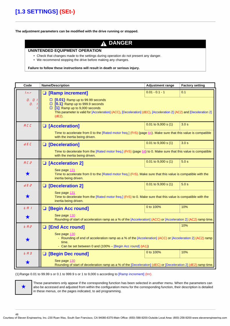
Courtes
[1.3 SETTINGS] (SEt-)
The adjustment parameters can be modified with the drive running or stopped.
(1)Range 0.01 to 99.99 s or 0.1 to 999.9 s or 1 to 9,000 s according to [Ramp increment] (Inr).
Code Name/Description Adjustment range Factory setting
Inr M [Ramp increment] 0.01 - 0.1 - 1 0.1
0.01
0.1
1
v [0.01]: Ramp up to 99.99 secondsv [0.1]: Ramp up to 999.9 secondsv [1]: Ramp up to 9,000 seconds
This parameter is valid for [Acceleration] (ACC), [Deceleration] (dEC), [Acceleration 2] (AC2) and [Deceleration 2] (dE2).
ACC M [Acceleration] 0.01 to 9,000 s (1) 3.0 s
Time to accelerate from 0 to the [Rated motor freq.] (FrS) (page 64). Make sure that this value is compatible with the inertia being driven.
dEC M [Deceleration] 0.01 to 9,000 s (1) 3.0 s
Time to decelerate from the [Rated motor freq.] (FrS) (page 64) to 0. Make sure that this value is compatible with the inertia being driven.
AC2 M [Acceleration 2] 0.01 to 9,000 s (1) 5.0 s
gSee page 131Time to accelerate from 0 to the [Rated motor freq.] (FrS). Make sure that this value is compatible with the inertia being driven.
dE2 M [Deceleration 2] 0.01 to 9,000 s (1) 5.0 s
gSee page 131Time to decelerate from the [Rated motor freq.] (FrS) to 0. Make sure that this value is compatible with the inertia being driven.
tA1 M [Begin Acc round] 0 to 100% 10%
g See page 130Rounding of start of acceleration ramp as a % of the [Acceleration] (ACC) or [Acceleration 2] (AC2) ramp time.
tA2 M [End Acc round] 10%
gSee page 130
- Rounding of end of acceleration ramp as a % of the [Acceleration] (ACC) or [Acceleration 2] (AC2) ramp time.
- Can be set between 0 and (100% – [Begin Acc round] (tA1))
tA3 M [Begin Dec round] 0 to 100% 10%
g See page 130Rounding of start of deceleration ramp as a % of the [Deceleration] (dEC) or [Deceleration 2] (dE2) ramp time.
gThese parameters only appear if the corresponding function has been selected in another menu. When the parameters can also be accessed and adjusted from within the configuration menu for the corresponding function, their description is detailed in these menus, on the pages indicated, to aid programming.
DANGERUNINTENDED EQUIPMENT OPERATION
• Check that changes made to the settings during operation do not present any danger.• We recommend stopping the drive before making any changes.
Failure to follow these instructions will result in death or serious injury.
48y of Steven Engineering, Inc.-230 Ryan Way, South San Francisco, CA 94080-6370-Main Office: (650) 588-9200-Outside Local Area: (800) 258-9200-www.stevenengineering.com

Courtes
[1.3 SETTINGS] (SEt-)
(1) In corresponds to the rated drive current indicated in the Installation Manual or on the drive nameplate.
Code Name/Description Adjustment range Factory setting
tA4 M [End Dec round] 10%
gSee page 130
- Rounding of end of deceleration ramp as a % of the [Deceleration] (dEC) or [Deceleration 2] (dE2) ramp time.
- Can be set between 0 and (100% – [Begin Dec round] (tA3))
LSP M [Low speed] 0 Hz
Motor frequency at minimum reference, can be set between 0 and [High speed] (HSP).
HSP M [High speed] 50 Hz
Motor frequency at maximum reference, can be set between [Low speed] (LSP) and [Max frequency] (tFr). The factory setting changes to 60 Hz if [Standard mot. freq] (bFr) = [60 Hz NEMA] (60).
ItH M [Mot. therm. current] 0 to 1.1 or 1.2 In (1) according to rating
According to drive rating
Motor thermal protection current, to be set to the rated current indicated on the nameplate.
SPG M [Speed prop. gain] 0 to 1,000% 40%
Speed loop proportional gain
SIt M [Speed time integral] 1 to 1,000% 100%
Speed loop integral time constant.
SFC M [K speed loop filter] 0 to 100 0
Speed loop filter coefficient.
gThese parameters only appear if the corresponding function has been selected in another menu. When the parameters can also be accessed and adjusted from within the configuration menu for the corresponding function, their description is detailed in these menus, on the pages indicated, to aid programming.
49y of Steven Engineering, Inc.-230 Ryan Way, South San Francisco, CA 94080-6370-Main Office: (650) 588-9200-Outside Local Area: (800) 258-9200-www.stevenengineering.com

Courtes
[1.3 SETTINGS] (SEt-)
Adjusting the [K speed loop filter] (SFC), [Speed prop. gain] (SPG), and [Speed time integral] (SIt) parameters
• The following parameters can only be accessed in vector control profiles: [Motor control type] (Ctt) page 67 = [SVC V] (UUC), [Energy Sav.] (nLd) and [Sync. mot.] (SYn).
• The factory settings are suitable for most applications.
General case: Setting with [K speed loop filter] (SFC) = 0The regulator is an “IP” type with filtering of the speed reference, for applications requiring flexibility and stability (high inertia, for example).
• [Speed prop. gain] (SPG) affects excessive speed.
• [Speed prop. gain] (SIt) affects the passband and response time.
Initial response Reduction in SIT Reduction in SIT
Initial response Increase in SPG Increase in SPG
0 500450400350300250200150100500
1
0,8
0,6
0,4
0,2
Reference division
Time in ms0 50045040035030025020015010050
0
1
0,8
0,6
0,4
0,2
Reference division
Time in ms0 50045040035030025020015010050
0
1
0,8
0,6
0,4
0,2
Reference division
Time in ms
0 500450400350300250200150100500
1
0,8
0,6
0,4
0,2
Reference division
Time in ms0 50045040035030025020015010050
0
1
0,8
0,6
0,4
0,2
Reference division
Time in ms0 50045040035030025020015010050
0
1
0,8
0,6
0,4
0,2
Reference division
Time in ms
50y of Steven Engineering, Inc.-230 Ryan Way, South San Francisco, CA 94080-6370-Main Office: (650) 588-9200-Outside Local Area: (800) 258-9200-www.stevenengineering.com

Courtes
[1.3 SETTINGS] (SEt-)
Special case: Parameter [K speed loop filter] (SFC) not 0This parameter must be reserved for specific applications that require a short response time (trajectory positioning or servo control).
- When set to 100 as described above the regulator is a “PI” type, without filtering of the speed reference.
- Settings between 0 and 100 will obtain an intermediate function between the settings below and those on the previous page.
Example: Setting with [K speed loop filter] (SFC) = 100
• [Speed prop. gain] (SPG) affects the passband and response time.
• [Speed time integral] (SIt) affects excessive speed.
Initial response Reduction in SIT Reduction in SIT
Initial response Increase in SPG Increase in SPG
0 500450400350300250200150100500
1
0,8
0,6
0,4
0,2
Reference division
Time in ms0 50045040035030025020015010050
0
1
0,8
0,6
0,4
0,2
Reference division
Time in ms0 50045040035030025020015010050
0
1
0,8
0,6
0,4
0,2
Reference division
Time in ms
0 500450400350300250200150100500
1
0,8
0,6
0,4
0,2
Reference division
Time in ms0 50045040035030025020015010050
0
1
0,8
0,6
0,4
0,2
Reference division
Time in ms0 50045040035030025020015010050
0
1
0,8
0,6
0,4
0,2
Reference division
Time in ms
51y of Steven Engineering, Inc.-230 Ryan Way, South San Francisco, CA 94080-6370-Main Office: (650) 588-9200-Outside Local Area: (800) 258-9200-www.stevenengineering.com

Courtes
[1.3 SETTINGS] (SEt-)
(1) In corresponds to the rated drive current indicated in the Installation Manual or on the drive nameplate.
Code Name/Description Adjustment range Factory setting
UFr M [IR compensation] 25 to 200% 100%
g See page 71
SLP M [Slip compensation] 0 to 300% 100%
g See page 71
dCF M [Ramp divider] 0 to 10 4
g See page 133
IdC M [DC inject. level 1] 0.1 to 1.1 or 1.2 In (1) according to rating
0.64 In (1)
g See page 134Level of DC injection braking current activated via logic input or selected as stop mode.
tdI M [DC injection time 1] 0.1 to 30 s 0.5 s
gSee page 134Maximum current injection time [DC inject. level 1] (IdC). After this time the injection current becomes [DC inject. level 2] (IdC2).
IdC2 M [DC inject. level 2] 0.1 In (1) to [DC inject. level 1] (IdC)
0.5 In (1)
g See page 134Injection current activated by logic input or selected as stop mode, once period of time [DC injection time 1] (tdI) has elapsed.
tdC M [DC injection time 2] 0.1 to 30 s 0.5 s
g See page 134Maximum injection time [DC inject. level 2] (IdC2) for injection selected as stop mode only.
gThese parameters only appear if the corresponding function has been selected in another menu. When the parameters can also be accessed and adjusted from within the configuration menu for the corresponding function, their description is detailed in these menus, on the pages indicated, to aid programming.
CAUTIONCheck that the motor will withstand this current without overheating.Failure to follow these instructions can result in equipment damage.
CAUTIONCheck that the motor will withstand this current without overheating.Failure to follow these instructions can result in equipment damage.
52y of Steven Engineering, Inc.-230 Ryan Way, South San Francisco, CA 94080-6370-Main Office: (650) 588-9200-Outside Local Area: (800) 258-9200-www.stevenengineering.com

Courtes
[1.3 SETTINGS] (SEt-)
(1) In corresponds to the rated drive current indicated in the Installation Manual or on the drive nameplate.
Code Name/Description Adjustment range Factory setting
SdC1 M [Auto DC inj. level 1] 0 to 1.1 or 1.2 In (1) according to rating
0.7 In (1)
g Level of standstill DC injection current. This parameter can be accessed if [Auto DC injection] (AdC) page 135 is not [No] (nO). This parameter is forced to 0 if [Motor control type] (Ctt) page 67 = [Sync. mot.] (SYn).
tdCI M [Auto DC inj. time 1] 0.1 to 30 s 0.5 s
gStandstill injection time. This parameter can be accessed if [Auto DC injection] (AdC) page 135 is not [No] (nO) If [Motor control type] (Ctt) page 67 = [Sync. mot.] (SYn) this time corresponds to the zero speed maintenance time.
SdC2 M [Auto DC inj. level 2] 0 to 1.1 or 1.2 In (1) according to rating
0.5 In (1)
g 2nd level of standstill DC injection current.This parameter can be accessed if [Auto DC injection] (AdC) page 135 is not [No] (nO).This parameter is forced to 0 if [Motor control type] (Ctt) page 67 = [Sync. mot.] (SYn).
tdC2 M [Auto DC inj. time 2] 0 to 30 s 0 s
g 2nd standstill injection time.This parameter can be accessed if [Auto DC injection] (AdC) page 135 = [Yes] (YES).
gThese parameters only appear if the corresponding function has been selected in another menu. When the parameters can also be accessed and adjusted from within the configuration menu for the corresponding function, their description is detailed in these menus, on the pages indicated, to aid programming.
CAUTIONCheck that the motor will withstand this current without overheating.Failure to follow these instructions can result in equipment damage.
CAUTIONCheck that the motor will withstand this current without overheating.Failure to follow these instructions can result in equipment damage.
AdC SdC2 Operation
YES
x
Ct
≠ 0
Ct = 0
Run command
Speed
t
SdC1
SdC2
tdC1 tdC1 + tdC2
I
t
SdC1I
t
SdC1
SdC2
tdC1
I
t0
t
1
0
53y of Steven Engineering, Inc.-230 Ryan Way, South San Francisco, CA 94080-6370-Main Office: (650) 588-9200-Outside Local Area: (800) 258-9200-www.stevenengineering.com

Courtes
[1.3 SETTINGS] (SEt-)
(1) In corresponds to the rated drive current indicated in the Installation Manual or on the drive nameplate.
Code Name/Description Adjustment range Factory setting
SFr M [Switching freq.] According to rating According to rating
Switching frequency setting.
Adjustment range: It can vary between 1 and 16 kHz, but the minimum and maximum values, as well as the factory setting, can be limited in accordance with the type of drive (ATV61H or W), the rating (power and voltage) and the configuration of the [Sinus filter] (OFI) and [Motor surge limit.] (SUL) parameters, page 75.
Adjustment with drive running: - If the initial value is less than 2 kHz, it is not possible to increase it above 1.9 kHz while running.- If the initial value is greater than or equal to 2 kHz, a minimum of 2 kHz must be maintained while running.Adjustment with the drive stopped: No restrictions.
Note: In the event of excessive temperature rise, the drive will automatically reduce the switching frequency and reset it once the temperature returns to normal..
CLI M [Current Limitation] 0 to 1.1 or 1.2 In (1) according to rating
1.1 or 1.2 In (1) according to rating
Used to limit the motor current.
Note: If the setting is less than 0.25 In, the drive may lock in [Output Phase Loss] (OPF) fault mode if this has been enabled (see page 192). If it is less than the no-load motor current, the limitation no longer has any effect..
CL2 M [I Limit. 2 value] 0 to 1.1 or 1.2 In (1) according to rating
1.1 or 1.2 In (1) according to rating
g
See page 166
Note: If the setting is less than 0.25 In, the drive may lock in [Output Phase Loss] (OPF) fault mode if this has been enabled (see page 192). If it is less than the no-load motor current, the limitation no longer has any effect..
gThese parameters only appear if the corresponding function has been selected in another menu. When the parameters can also be accessed and adjusted from within the configuration menu for the corresponding function, their description is detailed in these menus, on the pages indicated, to aid programming.
CAUTIONOn ATV61p075N4 to U40N4 drives, if the RFI filters are disconnected (operation on an IT system), the switching frequency of the drive must not exceed 4 kHz.Failure to follow this instruction can result in equipment damage.
CAUTIONCheck that the motor will withstand this current, particularly in the case of permanent magnet synchronous motors, which are susceptible to demagnetization.Failure to follow this instruction can result in equipment damage.
CAUTIONCheck that the motor will withstand this current, particularly in the case of permanent magnet synchronous motors, which are susceptible to demagnetization.Failure to follow this instruction can result in equipment damage.
54y of Steven Engineering, Inc.-230 Ryan Way, South San Francisco, CA 94080-6370-Main Office: (650) 588-9200-Outside Local Area: (800) 258-9200-www.stevenengineering.com

Courtes
[1.3 SETTINGS] (SEt-)
Code Name/Description Adjustment range Factory setting
FLU M [Motor fluxing] [No] (FnO)
FnC
FCt
FnO
v [Not cont.] (FnC): Non-continuous modev [Continuous] (FCt): Continuous mode. This option is not possible if [Auto DC injection] (AdC) page 135 is
[Yes] (YES) or if [Type of stop] (Stt) page 133 is [Freewheel] (nSt).v [No] (FnO): Function inactive.
At and above ATV61HD55M3X, ATV61HD90N4 and ATV61HC11Y, if [Motor control type] (Ctt) page 67 = [SVC V] (UUC) or [Energy Sav.] (nLd), this selection cannot be made and the factory setting is replaced by [Not cont.] (FnC).
If [Motor control type] (Ctt) = [Sync. mot.] (SYn) the factory setting is replaced by [Not cont.] (FnC).
In order to obtain rapid high torque on startup, magnetic flux needs to already have been established in the motor.• In [Continuous] (FCt) mode, the drive automatically builds up flux when it is powered up.• In [Not cont.] (FnC) mode, fluxing occurs when the motor starts up.
The flux current is greater than nCr (configured rated motor current) when the flux is established and is then adjusted to the motor magnetizing current...
If [Motor control type] (Ctt) page 67 = [Sync. mot.] (SYn), the [Motor fluxing] (FLU) parameter causes the alignment of the rotor and not the fluxing.
tLS M [Low speed time out] 0 to 999.9 s 0 s
Maximum operating time at [Low speed] (LSP) (see page 37)Following operation at LSP for a defined period, a motor stop is requested automatically. The motor restarts if the reference is greater than LSP and if a run command is still present.Caution: Value 0 corresponds to an unlimited period.
Note: If [Low speed time out] (tLS) is not 0, [Type of stop] (Stt) page 133 is forced to [Ramp stop] (rMP) (only if a ramp stop can be configured).
SLE M [Sleep Offset Thres.] 0 to 500 or 1,000 according to rating
1 Hz
Adjustable restart threshold (offset) following a stop after prolonged operation at [Low speed] (LSP), in Hz. The motor restarts if the reference rises above (LSP + SLE) and if a run command is still present.
JGF M [Jog frequency] 0 to 10 Hz 10 Hz
g See page 137Reference in jog operation
JGt M [Jog delay] 0 to 2.0 s 0.5 s
g See page 137Anti-repeat delay between 2 consecutive jog operations.
gThese parameters only appear if the corresponding function has been selected in another menu. When the parameters can also be accessed and adjusted from within the configuration menu for the corresponding function, their description is detailed in these menus, on the pages indicated, to aid programming.
CAUTIONCheck that the motor will withstand this current without overheating.Failure to follow these instructions can result in equipment damage.
55y of Steven Engineering, Inc.-230 Ryan Way, South San Francisco, CA 94080-6370-Main Office: (650) 588-9200-Outside Local Area: (800) 258-9200-www.stevenengineering.com

Courtes
[1.3 SETTINGS] (SEt-)
Code Name/Description Adjustment range Factory setting
SP2 M [Preset speed 2] 0 to 500 or 1,000 Hz according to rating
10 Hz
g See page 140Preset speed 2
SP3 M [Preset speed 3] 0 to 500 or 1,000 Hz according to rating
15 Hz
g See page 140Preset speed 3
SP4 M [Preset speed 4] 0 to 500 or 1,000 Hz according to rating
20 Hz
g See page 140Preset speed 4
SP5 M [Preset speed 5] 0 to 500 or 1,000 Hz according to rating
25 Hz
g See page 140Preset speed 5
SP6 M [Preset speed 6] 0 to 500 or 1,000 Hz according to rating
30 Hz
g See page 140Preset speed 6
SP7 M [Preset speed 7] 0 to 500 or 1,000 Hz according to rating
35 Hz
g See page 140Preset speed 7
SP8 M [Preset speed 8] 0 to 500 or 1,000 Hz according to rating
50 Hz
gSee page 140Preset speed 8The factory setting changes to 60 Hz if [Standard mot. freq] (bFr) = [60 Hz NEMA] (60).
gThese parameters only appear if the corresponding function has been selected in another menu. When the parameters can also be accessed and adjusted from within the configuration menu for the corresponding function, their description is detailed in these menus, on the pages indicated, to aid programming.
56y of Steven Engineering, Inc.-230 Ryan Way, South San Francisco, CA 94080-6370-Main Office: (650) 588-9200-Outside Local Area: (800) 258-9200-www.stevenengineering.com
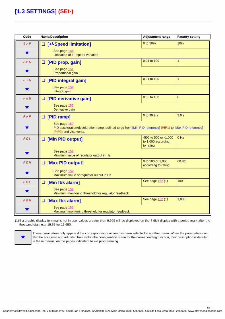
Courtes
[1.3 SETTINGS] (SEt-)
(1) If a graphic display terminal is not in use, values greater than 9,999 will be displayed on the 4-digit display with a period mark after the thousand digit, e.g. 15.65 for 15,650.
Code Name/Description Adjustment range Factory setting
SrP M [+/-Speed limitation] 0 to 50% 10%
g See page 144Limitation of +/- speed variation
rPG M [PID prop. gain] 0.01 to 100 1
g See page 151Proportional gain
rIG M [PID integral gain] 0.01 to 100 1
g See page 152Integral gain
rdG M [PID derivative gain] 0.00 to 100 0
g See page 152Derivative gain
PrP M [PID ramp] 0 to 99.9 s 3.0 s
gSee page 152PID acceleration/deceleration ramp, defined to go from [Min PID reference] (PIP1) to [Max PID reference] (PIP2) and vice versa.
POL M [Min PID output] -500 to 500 or -1,000 to 1,000 according to rating
0 Hz
g See page 152Minimum value of regulator output in Hz
POH M [Max PID output] 0 to 500 or 1,000 according to rating
60 Hz
g See page 152Maximum value of regulator output in Hz
PAL M [Min fbk alarm] See page 152 (1) 100
g See page 152Minimum monitoring threshold for regulator feedback
PAH M [Max fbk alarm] See page 152 (1) 1,000
g See page 152Maximum monitoring threshold for regulator feedback
gThese parameters only appear if the corresponding function has been selected in another menu. When the parameters can also be accessed and adjusted from within the configuration menu for the corresponding function, their description is detailed in these menus, on the pages indicated, to aid programming.
57y of Steven Engineering, Inc.-230 Ryan Way, South San Francisco, CA 94080-6370-Main Office: (650) 588-9200-Outside Local Area: (800) 258-9200-www.stevenengineering.com

Courtes
[1.3 SETTINGS] (SEt-)
(1) If a graphic display terminal is not in use, values greater than 9,999 will be displayed on the 4-digit display with a period mark after the thousand digit, e.g. 15.65 for 15,650.
Code Name/Description Adjustment range Factory setting
PEr M [PID error Alarm] 0 to 65,535 (1) 100
g See page 152Regulator error monitoring threshold.
PSr M [Speed input%] 1 to 100% 100%
g See page 153Multiplying coefficient for predictive speed input.
rP2 M [Preset ref. PID 2] See page 156 (1) 300
g See page 156Preset PID reference
rP3 M [Preset ref. PID 3] See page 156 (1) 600
g See page 156Preset PID reference
rP4 M [Preset ref. PID 4] See page 156 (1) 900
g See page 156Preset PID reference
LPI M [PID Threshold] 100
g
nO
-
See page 155PID regulator feedback supervision threshold (alarm can be assigned to a relay or a logic output, page 94).Adjustment range:
v [No] (nO): Function inactivev between [Min PID feedback] (PIF1) and [Max PID feedback] (PIF2) (2).
tPI M [PID Ctrl. time delay] 0 to 600 s 0 s
g See page 155PID regulator feedback supervision time delay
gThese parameters only appear if the corresponding function has been selected in another menu. When the parameters can also be accessed and adjusted from within the configuration menu for the corresponding function, their description is detailed in these menus, on the pages indicated, to aid programming.
58y of Steven Engineering, Inc.-230 Ryan Way, South San Francisco, CA 94080-6370-Main Office: (650) 588-9200-Outside Local Area: (800) 258-9200-www.stevenengineering.com

Courtes
[1.3 SETTINGS] (SEt-)
(1) In corresponds to the rated drive current indicated in the Installation Manual or on the drive nameplate.
Code Name/Description Adjustment range Factory setting
tLIM M [Motoring torque lim] 0 to 300% 100%
gSee page 164Torque limitation in motor mode, as a whole % or in 0.1% increments of the rated torque in accordance with the [Torque increment] (IntP) parameter, page 164.
tLIG M [Gen. torque lim] 0 to 300% 100%
gSee page 164Torque limitation in generator mode, as a whole % or in 0.1% increments of the rated torque in accordance with the [Torque increment] (IntP) parameter, page 164.
Ctd M [Current threshold] 0 to 1.1 or 1.2 In (1) according to rating
In (1)
Upper current threshold for [I attained] (CtA) function assigned to a relay or a logic output (see page 94).
CtdL M [Low I Threshold] 0 to 1.1 or 1.2 In (1) according to rating
0
Lower current threshold for [Low I Th.At.] (CtAL) function assigned to a relay or a logic output (see page 94).
ttH M [High torque thd.] -300% to +300% 100%
High current threshold for [High tq. att.] (ttHA) function assigned to a relay or a logic output (see page 94), as a % of the rated motor torque.
ttL M [Low torque thd.] -300% to +300% 50%
Low current threshold for [Low tq. att.] (ttLA) function assigned to a relay or a logic output (see page 94), as a % of the rated motor torque.
FqL M [Pulse warning thd.] 0 Hz to 30.00 kHz 0 Hz
g Speed threshold measured by the [FREQUENCY METER] (FqF-) function, page 203, assigned to a relay or a logic output (see page 95).
Ftd M [Freq. threshold] 0 to 500 or 1,000 Hz according to rating
[Standard mot. freq] (bFr)
High frequency threshold for the [Freq.Th.att.] (FtA) function assigned to a relay or a logic output (see page 94), or used by the [PARAM. SET SWITCHING] (MLP-) function, page 174.
FtdL M [Low Freq.Threshold] 0 to 500 or 1,000 Hz according to rating
0
Lower frequency threshold for [Low Frq. Th. Attain.] (FtAL) function assigned to a relay or a logic output (see page 94).
F2d M [Frequency 2 threshold] 0 to 500 or 1,000 Hz according to rating
[Standard mot. freq] (bFr)
Frequency threshold for [Freq. Th. 2 attain.] (F2A) function assigned to a relay or a logic output (see page 94), or used by the [PARAM. SET SWITCHING] (MLP-) function, page 174.
F2dL M [2 Freq. Threshold] 0 to 500 or 1,000 Hz according to rating
0
Lower frequency threshold for [2Low F.Thld] (F2AL) function assigned to a relay or a logic output (see page 94).
gThese parameters only appear if the corresponding function has been selected in another menu. When the parameters can also be accessed and adjusted from within the configuration menu for the corresponding function, their description is detailed in these menus, on the pages indicated, to aid programming.
59y of Steven Engineering, Inc.-230 Ryan Way, South San Francisco, CA 94080-6370-Main Office: (650) 588-9200-Outside Local Area: (800) 258-9200-www.stevenengineering.com

Courtes
[1.3 SETTINGS] (SEt-)
(1) In corresponds to the rated drive current indicated in the Installation Manual or on the drive nameplate.
Code Name/Description Adjustment range Factory setting
FFt M [Freewheel stop Thd] 0.0 to 1000 Hz 0.0
See page 133This parameter supports switching from a ramp stop or a fast stop to a freewheel stop below a low speed threshold. It can be accessed if [Type of stop] (Stt) = [Fast stop] (FSt) or [Ramp stop] (rMP).v 0.0: Does not switch to freewheel stop.v 0.1 to 1000 Hz: Speed threshold below which the motor will switch to freewheel stop.
ttd M [Motor therm. level] 0 to 118% 100%
g See page 192Trip threshold for motor thermal alarm (logic output or relay)
rtd M [High Freq. Ref. Thr.] 0 to 500 or 1,000 Hz according to rating
0
Upper frequency reference threshold for [High Ref.] (rtAH) function assigned to a relay or a logic output (see page 94).
rtdL M [Low Freq. Ref. Thr.] 0 to 500 or 1,000 Hz according to rating
0
Lower frequency reference threshold for [Low Ref.] (rtAL) function assigned to a relay or a logic output (see page 94).
gThese parameters only appear if the corresponding function has been selected in another menu. When the parameters can also be accessed and adjusted from within the configuration menu for the corresponding function, their description is detailed in these menus, on the pages indicated, to aid programming.
60y of Steven Engineering, Inc.-230 Ryan Way, South San Francisco, CA 94080-6370-Main Office: (650) 588-9200-Outside Local Area: (800) 258-9200-www.stevenengineering.com

Courtesy
[1.3 SETTINGS] (SEt-)
Code Name/Description Adjustment range Factory setting
JPF M [Skip Freq.] 0 to 500 or 1,000 Hz according to rating
0 Hz
Skip frequency. This parameter prevents prolonged operation within an adjustable range around the regulated frequency. This function can be used to prevent a critical speed, which would cause resonance, being reached. Setting the function to 0 renders it inactive.
JF2 M [Skip Freq. 2] 0 to 500 or 1,000 Hz according to rating
0 Hz
2nd skip frequency. This parameter prevents prolonged operation within an adjustable range around the regulated frequency. This function can be used to prevent a critical speed, which would cause resonance, being reached. Setting the function to 0 renders it inactive.
JF3 M [3rd Skip Frequency] 0 to 500 or 1,000 Hz according to rating
0 Hz
3rd skip frequency. This parameter prevents prolonged operation within an adjustable range around the regulated frequency. This function can be used to prevent a critical speed, which would cause resonance, being reached. Setting the function to 0 renders it inactive.
JFH M [Skip.Freq.Hysteresis] 0.1 to 10 Hz 1 Hz
Parameter visible if at least one skip frequency [Skip Frequency] (JPF), [Skip Frequency 2] (JF2) or [3rd Skip Frequency] (JF3) is different from 0.Skip frequency range: between (JPF – JFH) and (JPF + JFH), for example.This adjustment is common to all 3 frequencies (JPF, JF2 and JF3).
LUn M [Unld.Thr.Nom.Speed] 20 to 100% 60%
g See page 207.Underload threshold at rated motor frequency ([Rated motor freq.] (FrS) page 35), as a % of the rated motor torque.
LUL M [Unld.Thr.0.Speed] 0 to [Unld.Thr.Nom.Speed] (LUn)
0%
g See page 207.Underload threshold at zero frequency, as a % of the rated motor torque.
rMUd M [Unld. Freq.Thr. Det.] 0 to 500 or 1,000 Hz according to rating
0 Hz
g See page 207.Underload detection minimum frequency threshold
Srb M [Hysteresis Freq.Att.] 0.3 to 500 or 1,000 Hz according to rating
0.3 Hz
g See pages 207 and 208.Maximum deviation between the frequency reference and the motor frequency, which defines steady state operation.
FtU M [Underload T.B.Rest.] 0 to 6 min 0 min
g See page 207.Minimum time permitted between an underload being detected and any automatic restart.In order for an automatic restart to be possible, the value of [Max. restart time] (tAr) page 189 must exceed that of this parameter by at least one minute.
gThese parameters only appear if the corresponding function has been selected in another menu. When the parameters can also be accessed and adjusted from within the configuration menu for the corresponding function, their description is detailed in these menus, on the pages indicated, to aid programming.
61 of Steven Engineering, Inc.-230 Ryan Way, South San Francisco, CA 94080-6370-Main Office: (650) 588-9200-Outside Local Area: (800) 258-9200-www.stevenengineering.com

Courtes
[1.3 SETTINGS] (SEt-)
(1)Range 0.01 to 99.99 s or 0.1 to 999.9 s or 1 to 9,000 s according to [Ramp increment] (Inr).
Code Name/Description Adjustment range Factory setting
LOC M [Ovld Detection Thr.] 70 to 150% 110%
g See page 208.Overload detection threshold, as a % of the rated motor current [Rated mot. current] (nCr). This value must be less than the limit current in order for the function to work.
FtO M [Overload T.B.Rest.] 0 to 6 min 0 min
g See page 208.Minimum time permitted between an overload being detected and any automatic restart.In order for an automatic restart to be possible, the value of [Max. restart time] (tAr) page 189 must exceed that of this parameter by at least one minute.
FFd M [NoFlo.Freq.Thres.Ac.] 0 to 500 or 1,000 Hz according to rating
0 Hz
g See page 181.Zero flow detection activation thresholdThe parameter can be accessed if [PID feedback ass.] (PIF) is not [No] (nO) and if [No Flow Period Det.] (nFd) is not 0.
LFd M [No Flow Offset] 0 to 500 or 1,000 Hz according to rating
0 Hz
g See page 181.Zero flow detection offsetThe parameter can be accessed if [PID feedback ass.] (PIF) is not [No] (nO) and if [No Flow Period Det.] (nFd) is not 0.
nFFt M [Freq.Th.Sensor. Act.] 0 to 500 or 1,000 Hz according to rating
0 Hz
g See page 181.Zero fluid detection activation thresholdThe parameter can be accessed if [No Flow Sensor] (nFS) is not [No] (nO).
nFSt M [Flow Times Ctrl] 0 to 999 s 10 s
g See page 181.Zero fluid detection activation time delayThe parameter can be accessed if [No Flow Sensor] (nFS) is not [No] (nO).
CHt M [Flow.Lim.Th.Active] 0 to 100% 0%
g See page 183.Function activation threshold, as a % of the max. signal of the assigned inputThe parameter can be accessed if [Flow.Sen.Inf] (CHI) is not [No] (nO).
rCHt M [Flo.Lim.Thres. Inact.] 0 to 100% 0%
g See page 183.Function deactivation threshold, as a % of the max. signal of the assigned inputThe parameter can be accessed if [Flow.Sen.Inf] (CHI) is not [No] (nO).
dFL M [Dec. Flow. limit] 0.01 to 9,000 s (1) 5.0 s
g See page 183. The parameter can be accessed if [Flow.Sen.Inf] (CHI) is not [No] (nO). Time to decelerate from [Rated motor freq.] (FrS) to 0. Make sure that this value is compatible with the inertia being driven.
gThese parameters only appear if the corresponding function has been selected in another menu. When the parameters can also be accessed and adjusted from within the configuration menu for the corresponding function, their description is detailed in these menus, on the pages indicated, to aid programming.
62y of Steven Engineering, Inc.-230 Ryan Way, South San Francisco, CA 94080-6370-Main Office: (650) 588-9200-Outside Local Area: (800) 258-9200-www.stevenengineering.com

Courtes
[1.4 MOTOR CONTROL] (drC-)
With graphic display terminal:
With integrated display terminal:
RDY Term +0.00 Hz REMMAIN MENU
1 DRIVE MENU2 ACCESS LEVEL3 OPEN / SAVE AS4 PASSWORD5 LANGUAGE
Code T/K
ENT
RDY Term +0.00 Hz REM1 DRIVE MENU
1.1 SIMPLY START1.2 MONITORING1.3 SETTINGS1.4 MOTOR CONTROL1.5 INPUTS / OUTPUTS CFG
Code << >> T/K
ENTRUN Term +0.00 Hz REM
1.4 MOTOR CONTROLStandard mot. freqRated motor powerRated motor volt.Rated mot. currentRated motor freq.
Code << >> T/K
XXX
SIM-
I-O-
ESC
ESC
ESC
ESC
ENT
ENT
ESC
LAC-
drC-
Displays the drive state
MOTOR CONTROL
Power-up
63y of Steven Engineering, Inc.-230 Ryan Way, South San Francisco, CA 94080-6370-Main Office: (650) 588-9200-Outside Local Area: (800) 258-9200-www.stevenengineering.com

Courtes
[1.4 MOTOR CONTROL] (drC-)
The parameters in the [1.4 MOTOR CONTROL] (drC-) menu can only be modified when the drive is stopped and no run command is present, with the following exceptions:
• [Auto tuning] (tUn) page 66, which causes the motor to start up.• Parameters containing the sign in the code column, which can be modified with the drive running or stopped.
(1) In corresponds to the rated drive current indicated in the Installation Manual and on the drive nameplate.
Code Name/Description Adjustment range Factory setting
bFr M [Standard mot. freq] [50Hz IEC] (50)
50
60
v [50Hz IEC] (50): IEC.v [60Hz NEMA] (60): NEMA.
This parameter modifies the presets of parameters [Rated motor power] (nPr), [Rated motor volt.] (UnS), [Rated mot. current] (nCr), [Rated motor freq.] (FrS), [Rated motor speed] (nSP) and [Max frequency] (tFr) below, [Mot. therm. current] (ItH) page 49, [High speed] (HSP) page 49, [Freq. threshold] (Ftd) page 59, [Freq. threshold 2] (F2d) page 59, [V. constant power] (UCP) page 69, [Freq. Const Power] (FCP) page 69, [Nominal freq sync.] (FrSS) page 70, [Preset speed 8] (SP8) page 140, [Forced Run Ref.] (InHr) page 199.
nPr M [Rated motor power] According to drive rating
According to drive rating
The parameter cannot be accessed if [Motor control type] (Ctt) page 67 = [Sync. mot.] (SYn)Rated motor power given on the nameplate, in kW if [Standard mot. freq] (bFr) = [50 Hz IEC] (50), in HP if [Standard mot. freq] (bFr) = [60 Hz NEMA] (60).
UnS M [Rated motor volt.] According to drive rating
According to drive rating and [Standard mot. freq] (bFr)
The parameter cannot be accessed if [Motor control type] (Ctt) page 67 = [Sync. mot.] (SYn)Rated motor voltage given on the nameplate.ATV61pppM3X: 100 to 240 VATV61pppN4: 200 to 480 VATV61pppY: 400 to 690 V
nCr M [Rated mot. current] 0.25 to 1.1 or 1.2 In (1) according to rating
According to drive rating and [Standard mot. freq] (bFr)
The parameter cannot be accessed if [Motor control type] (Ctt) page 67 = [Sync. mot.] (SYn)Rated motor current given on the nameplate.
FrS M [Rated motor freq.] 10 to 500 or 1,000 Hz according to rating
50 Hz
The parameter cannot be accessed if [Motor control type] (Ctt) page 67 = [Sync. mot.] (SYn)Rated motor frequency given on the nameplate.The factory setting is 50 Hz, or preset to 60 Hz if [Standard mot. freq] (bFr) is set to 60 Hz.The maximum value is limited to 500 Hz if [Motor control type] (Ctt) (page 67) is not V/F or if the drive rating is higher than ATV61HD37p or ATV61WD45p or if the drive is an ATV61pppY (500 to 690 V). Values between 500 Hz and 1000 Hz are only possible in V/F control and for powers limited to 37 kW (50 HP) for the ATV61H ppp and 45 kW (60 HP) for ATV61Wppp. In this case, configure [Motor control type] (Ctt) before [Rated motor freq.] (FrS).
64y of Steven Engineering, Inc.-230 Ryan Way, South San Francisco, CA 94080-6370-Main Office: (650) 588-9200-Outside Local Area: (800) 258-9200-www.stevenengineering.com

Courtes
[1.4 MOTOR CONTROL] (drC-)
Code Name/Description Adjustment range Factory setting
nSP M [Rated motor speed] 0 to 60,000 rpm According to drive rating
The parameter cannot be accessed if [Motor control type] (Ctt) page 67 = [Sync. mot.] (SYn)Rated motor speed given on the nameplate.0 to 9,999 rpm then 10.00 to 60.00 krpm on the integrated display terminal.If, rather than the rated speed, the nameplate indicates the synchronous speed and the slip in Hz or as a %, calculate the rated speed as follows:
• Nominal speed = Synchronous speed x or
• Nominal speed = Synchronous speed x (50 Hz motors) or
• Nominal speed = Synchronous speed x (60 Hz motors)
tFr M [Max frequency] 10 to 500 or 1,000 Hz according to rating
60 Hz
The factory setting is 60 Hz, or preset to 72 Hz if [Standard mot. freq] (bFr) is set to 60 Hz.The maximum value is limited by the following conditions:• It must not exceed 10 times the value of de [Rated motor freq.] (FrS)• It cannot exceed 500 Hz if the [Motor control type] (Ctt) (page 67) is not V/F or if the drive rating is higher
than ATV61HD37p or ATV61WD45p, or if the drive is an ATV61pppY (500 to 690 V). Values between 500 Hz and 1000 Hz are only possible in V/F control and for powers limited to 37 kW (50 HP) for the ATV61H ppp and 45 kW (60 HP) for ATV61Wppp. In this case, configure [Motor control type] (Ctt) before [Max frequency] (tFr).
100 - slip as a %100
50 - slip in Hz50
60 - slip in Hz60
65y of Steven Engineering, Inc.-230 Ryan Way, South San Francisco, CA 94080-6370-Main Office: (650) 588-9200-Outside Local Area: (800) 258-9200-www.stevenengineering.com

Courtes
[1.4 MOTOR CONTROL] (drC-)
(1)The parameter can also be accessed in the [1.3 SETTINGS] (SEt-) menu.
Code Name/Description Factory setting
tUn M [Auto tuning] [No] (nO)
nO
YES
dOnE
v [No] (nO): Auto-tuning not performed.v [Yes] (YES): Auto-tuning is performed as soon as possible, then the parameter automatically changes
to [Done] (dOnE).v [Done] (dOnE): Use of the values given the last time auto-tuning was performed.
Caution: • It is essential that all the motor parameters are correctly configured before starting auto-tuning.
- Asynchronous motor: [Rated motor volt.] (UnS), [Rated motor freq.] (FrS), [Rated mot. current] (nCr), [Rated motor speed] (nSP), [Rated motor power] (nPr)
- Synchronous motor: [Nominal I sync.] (nCrS), [Nom motor spdsync] (nSPS), [Pole pairs] (PPnS), [Syn. EMF constant] (PHS), [Autotune L d-axis] (LdS), [Autotune L q-axis] (LqS)
If one or more of these parameters is modified after auto-tuning has been performed, [Auto tuning] (tUn) will return to [No] (nO) and the procedure must be repeated.• Auto-tuning is only performed if no stop command has been activated. If a “freewheel stop” or “fast stop”
function has been assigned to a logic input, this input must be set to 1 (active at 0).• Auto-tuning takes priority over any run or prefluxing commands, which will be taken into account after the
auto-tuning sequence.• If auto-tuning fails, the drive displays [No] (nO) and, depending on the configuration of [Autotune fault mgt]
(tnL) page 204, may switch to [Auto-tuning] (tnF) fault mode.• Auto-tuning may last for 1 to 2 seconds. Do not interrupt the process. Wait for the display to change to
“[Done] (dOnE)” or “[No] (nO)”.
Note: During auto-tuning the motor operates at rated current.
AUt M [Automatic autotune] [No] (nO)
nO
YES
v [No] (nO): Function inactivev [Yes] (YES): Auto-tuning is performed on every power-up.
Caution: Same comments as for [Auto tuning] (tUn) above.If [Profile] (CHCF) = [8 serie] (SE8), then [Automatic autotune] (AUt) is fixed to [No] (nO).
tUS M [Auto tuning status] [Not done] (tAb)
tAb
PEnd
PrOG
FAIL
dOnE
CUS
For information only, cannot be modified.v [Not done] (tAb): The default stator resistance value is used to control the motor.v [Pending] (PEnd): Auto-tuning has been requested but not yet performed.v [In Progress] (PrOG): Auto-tuning in progressv [Failed] (FAIL): Auto-tuning has failed.v [Done] (dOnE): The stator resistance measured by the auto-tuning function is used to control the motor.v [Customized] (CUS): Auto-tuning has been performed, but at least one parameter set by this auto-tuning
operation has subsequently been modified. The [Auto tuning] (tUn) parameter then returns to [No] (nO). The following auto-tuning parameters are concerned: [Cust. stator R syn] (rSAS) page 70, [R1w] (rSA), [Idw] (IdA), [LFw] (LFA) and [T2w] (trA) page 72.
PHr M [Output Ph rotation] ABC
AbC
ACb
v [ABC] (AbC): Forwardv [ACB] (ACb): Reverse
This parameter can be used to reverse the direction of rotation of the motor without reversing the wiring.
66y of Steven Engineering, Inc.-230 Ryan Way, South San Francisco, CA 94080-6370-Main Office: (650) 588-9200-Outside Local Area: (800) 258-9200-www.stevenengineering.com

Courtes
[1.4 MOTOR CONTROL] (drC-)
Code Name/Description Adjustment range Factory setting
Ctt M [Motor control type] [Energy Sav.] (nLd)
UUC
UF2
UF5
SYn
UFq
nLd
v [SVC V] (UUC): Open-loop voltage flux vector control with automatic slip compensation according to the load. It supports operation with a number of motors connected in parallel on the same drive (if the motors are identical).
v [V/F 2pts] (UF2): Simple V/F profile without slip compensation. It supports operation with: - Special motors (wound rotor, tapered rotor, etc.)- A number of motors in parallel on the same drive- High-speed motors- Motors with a low power rating in comparison to that of the drive
v [V/F 5pts] (UF5): 5-segment V/F profile: As V/F 2 pts profile but also supports the avoidance of resonance (saturation).
v [Sync. mot.] (SYn): For synchronous permanent magnet motors with sinusoidal electromotive force (EMF) only. This selection is prohibited with ATV61ppppY (500 to 690 V). This selection makes the asynchronous motor parameters inaccessible, and the synchronous motor parameters accessible.
v [U/F Quad.] (UFq): Variable torque. For pump and fan applications.
v [Energy Sav.] (nLd): Energy saving. For applications that do not require high dynamics. This type of control is recommended when replacing an ATV38.
Voltage
Frequency
FrS
UnS
U0
The profile is defined by the values of parameters UnS, FrS and U0.
Voltage
FrequencyFrS
UnS
U5
U4
U3
U1
U2
U0
F1 F2 F3 F4 F5FrS > F5 > F4 > F3 > F2 > F1
The profile is defined by the values of parameters UnS, FrS, U0 to U5 and F0 to F5.
67y of Steven Engineering, Inc.-230 Ryan Way, South San Francisco, CA 94080-6370-Main Office: (650) 588-9200-Outside Local Area: (800) 258-9200-www.stevenengineering.com

Courtes
[1.4 MOTOR CONTROL] (drC-)
Code Name/Description Adjustment range Factory setting
PFL M [U/F Profile] 0 to 100% 20
Adjustment of the [U/F Quad.] (UFq) ratio. The parameter can be accessed if [Motor control type] (Ctt) = [U/F Quad.] (UFq).It defines the magnetizing current at zero frequency, as a % of the rated magnetizing current.
U0 M [U0] 0 to 600 or 1,000 V according to rating
0
V/f ratioThe parameter can be accessed if [Motor control type] (Ctt) = [V/F 2pts] (UF2) or [V/F 5pts] (UF5) or [U/F Quad.] (UFq).
U1 M [U1] 0 to 600 or 1,000 V according to rating
0
V/F profile setting. The parameter can be accessed if [Motor control type] (Ctt) = [V/F 5pts] (UF5)
F1 M [F1] 0 to 1,000 Hz 0
V/F profile setting. The parameter can be accessed if [Motor control type] (Ctt) = [V/F 5pts] (UF5)
U2 M [U2] 0 to 600 or 1,000 V according to rating
0
V/F profile setting. The parameter can be accessed if [Motor control type] (Ctt) = [V/F 5pts] (UF5)
F2 M [F2] 0 to 1,000 Hz 0
V/F profile setting. The parameter can be accessed if [Motor control type] (Ctt) = [V/F 5pts] (UF5)
U3 M [U3] 0 to 600 or 1,000 V according to rating
0
V/F profile setting. The parameter can be accessed if [Motor control type] (Ctt) = [V/F 5pts] (UF5)
F3 M [F3] 0 to 1,000 Hz 0
V/F profile setting. The parameter can be accessed if [Motor control type] (Ctt) = [V/F 5pts] (UF5)
Parameter that can be modified during operation or when stopped.
FrequencyFrS
PFL
0
100%
Magnetizing current
68y of Steven Engineering, Inc.-230 Ryan Way, South San Francisco, CA 94080-6370-Main Office: (650) 588-9200-Outside Local Area: (800) 258-9200-www.stevenengineering.com
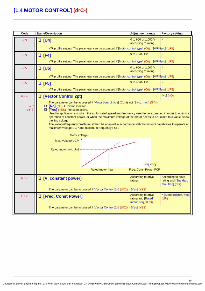
Courtes
[1.4 MOTOR CONTROL] (drC-)
Code Name/Description Adjustment range Factory setting
U4 M [U4] 0 to 600 or 1,000 V according to rating
0
V/F profile setting. The parameter can be accessed if [Motor control type] (Ctt) = [V/F 5pts] (UF5)
F4 M [F4] 0 to 1,000 Hz 0
V/F profile setting. The parameter can be accessed if [Motor control type] (Ctt) = [V/F 5pts] (UF5)
U5 M [U5] 0 to 600 or 1,000 V according to rating
0
V/F profile setting. The parameter can be accessed if [Motor control type] (Ctt) = [V/F 5pts] (UF5)
F5 M [F5] 0 to 1,000 Hz 0
V/F profile setting. The parameter can be accessed if [Motor control type] (Ctt) = [V/F 5pts] (UF5)
UC2 M [Vector Control 2pt] [No] (nO)
nO
YES
The parameter can be accessed if [Motor control type] (Ctt) is not [Sync. mot.] (SYn).v [No] (nO): Function inactivev [Yes] (YES): Function active.
Used in applications in which the motor rated speed and frequency need to be exceeded in order to optimize operation at constant power, or when the maximum voltage of the motor needs to be limited to a value below the line voltage.The voltage/frequency profile must then be adapted in accordance with the motor's capabilities to operate at maximum voltage UCP and maximum frequency FCP.
UCP M [V. constant power] According to drive rating
According to drive rating and [Standard mot. freq] (bFr)
The parameter can be accessed if [Vector Control 2pt] (UC2) = [Yes] (YES)
FCP M [Freq. Const Power] According to drive rating and [Rated motor freq.] (FrS)
= [Standard mot. freq] (bFr)
The parameter can be accessed if [Vector Control 2pt] (UC2) = [Yes] (YES)
Motor voltage
Frequency
Rated motor freq.
Max. voltage UCP
Freq. Const Power FCP
Rated motor volt. UnS
69y of Steven Engineering, Inc.-230 Ryan Way, South San Francisco, CA 94080-6370-Main Office: (650) 588-9200-Outside Local Area: (800) 258-9200-www.stevenengineering.com

Courtes
[1.4 MOTOR CONTROL] (drC-)
Synchronous motor parametersThese parameters can be accessed if [Motor control type] (Ctt) page 67 = [Sync. mot.] (SYn). In this case, the asynchronous motor parameters cannot be accessed.
(1) In corresponds to the rated drive current indicated in the Installation Manual and on the drive nameplate.
Synchronous motor parameters that can be accessed in [Expert] mode
Code Name/Description Adjustment range Factory setting
nCrS M [Nominal I sync.] 0.25 to 1.1 or 1.2 Hz according to rating (1)
According to drive rating
Rated synchronous motor current given on the nameplate.
nSPS M [Nom motor spdsync] 0 to 60,000 rpm According to drive rating
Rated motor speed given on the nameplate. On the integrated display unit: 0 to 9,999 rpm then 10.00 to 60.00 krpm.
PPnS M [Pole pairs] 1 to 50 According to drive rating
Number of pairs of poles on the synchronous motor.
PHS M [Syn. EMF constant] 0 to 6,553.5 According to drive rating
Synchronous motor EMF constant, in mV per rpm.
LdS M [Autotune L d-axis] 0 to 655.3 According to drive rating
Axis “d” stator inductance in mH. On motors with smooth poles [Autotune L d-axis] (LdS) = [Autotune L q-axis] (LqS) = Stator inductance L.
LqS M [Autotune L q-axis] 0 to 655.3 According to drive rating
Axis “q” stator inductance in mH. On motors with smooth poles [Autotune L d-axis] (LdS) = [Autotune L q-axis] (LqS) = Stator inductance L.
rSAS M [Cust. stator R syn] According to drive rating
According to drive rating
Cold state stator resistance (per winding) The factory setting is replaced by the result of the auto-tuning operation, if it has been performed. The value can be entered by the user, if he knows it. Value in milliohms (mΩ) up to 75 kW (100 HP), in hundredths of milliohms (mΩ/100) above 75 kW (100 HP).On the integrated display unit: 0 to 9,999 then 10.00 to 65.53 (10,000 to 65,536).
Code Name/Description
rSMS M [R1rS]Cold state stator resistance (per winding), in read-only mode. This is the drive factory setting or the result of the auto-tuning operation, if it has been performed.Value in milliohms (mΩ) up to 75 kW (100 HP), in hundredths of milliohms (mΩ/100) above 75 kW (100 HP).On the integrated display unit: 0 to 9,999 then 10.00 to 65.53 (10,000 to 65,536).
FrSS M [Nominal freq sync.]Motor frequency at rated speed in Hz, calculated by the drive (rated motor frequency), in read-only mode.
70y of Steven Engineering, Inc.-230 Ryan Way, South San Francisco, CA 94080-6370-Main Office: (650) 588-9200-Outside Local Area: (800) 258-9200-www.stevenengineering.com
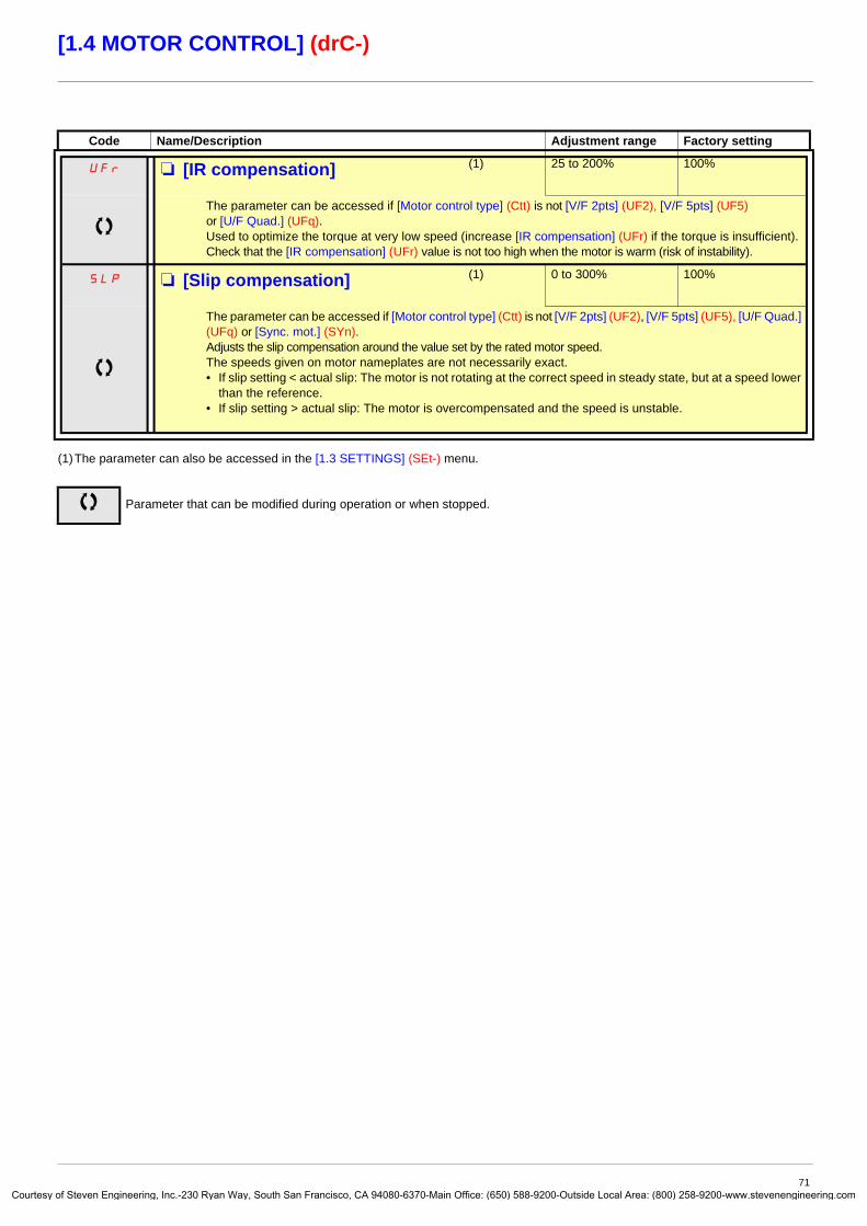
Courtes
[1.4 MOTOR CONTROL] (drC-)
(1)The parameter can also be accessed in the [1.3 SETTINGS] (SEt-) menu.
Code Name/Description Adjustment range Factory setting
UFr M [IR compensation] (1) 25 to 200% 100%
The parameter can be accessed if [Motor control type] (Ctt) is not [V/F 2pts] (UF2), [V/F 5pts] (UF5) or [U/F Quad.] (UFq).Used to optimize the torque at very low speed (increase [IR compensation] (UFr) if the torque is insufficient).Check that the [IR compensation] (UFr) value is not too high when the motor is warm (risk of instability).
SLP M [Slip compensation] (1) 0 to 300% 100%
The parameter can be accessed if [Motor control type] (Ctt) is not [V/F 2pts] (UF2), [V/F 5pts] (UF5), [U/F Quad.] (UFq) or [Sync. mot.] (SYn).Adjusts the slip compensation around the value set by the rated motor speed.The speeds given on motor nameplates are not necessarily exact.• If slip setting < actual slip: The motor is not rotating at the correct speed in steady state, but at a speed lower
than the reference.• If slip setting > actual slip: The motor is overcompensated and the speed is unstable.
Parameter that can be modified during operation or when stopped.
71y of Steven Engineering, Inc.-230 Ryan Way, South San Francisco, CA 94080-6370-Main Office: (650) 588-9200-Outside Local Area: (800) 258-9200-www.stevenengineering.com

Courtes
[1.4 MOTOR CONTROL] (drC-)
Parameter can be accessed in [Expert] mode.
Asynchronous motor parameters that can be accessed in [Expert] modeThese parameters can be accessed if [Motor control type] (Ctt) page 67 is not [Sync. mot.] (SYn).These include:
• Parameters calculated by the drive during auto-tuning, in read-only mode. For example, R1r, calculated cold stator resistance.• The possibility of replacing some of these calculated parameters by other values, if necessary. For example, R1w, measured
cold stator resistance.When a parameter Xyw is modified by the user, the drive uses it in place of the calculated parameter Xyr.
If auto-tuning is performed or if one of the motor parameters on which auto-tuning depends is modified ([Rated motor volt.] (UnS), [Rated motor freq.] (FrS), [Rated mot. current] (nCr), [Rated motor speed] (nSP), [Rated motor power] (nPr)), parameters Xyw return to their factory settings.
Code Name/Description
Prt M [Power Ident]Parameter reserved for Schneider Electric product support. Do not modify.To modify this parameter with the integrated terminal, press and hold down the “ENT” key for 2 s.
Code Name/Description
rSM M [Stator R measured]Cold stator resistance, calculated by the drive, in read-only mode. Value in milliohms (mΩ) up to 75 kW (100 HP), in hundredths of milliohms (mΩ/100) above 75 kW (100 HP).
IdM M [Idr]Magnetizing current in A, calculated by the drive, in read-only mode.
LFM M [Lfr]Leakage inductance in mH, calculated by the drive, in read-only mode.
trM M [T2r]Rotor time constant in mS, calculated by the drive, in read-only mode.
nSL M [Nominal motor slip]Rated slip in Hz, calculated by the drive, in read-only mode. To modify the rated slip, modify the [Rated motor speed] (nSP) (page 65).
PPn M [Pr]Number of pairs of poles, calculated by the drive, in read-only mode.
rSA M [R1w]Cold state stator resistance (per winding), modifiable value. In milliohms (mΩ) up to 75 kW (100 HP), in hundredths of milliohms (mΩ/100) above 75 kW (100 HP). On the integrated display unit: 0 to 9,999 then 10.00 to 65.53 (10,000 to 65,536).
IdA M [Idw]Magnetizing current in A, modifiable value.
LFA M [Lfw]Leakage inductance in mH, modifiable value.
trA M [T2w]Rotor time constant in mS, modifiable value.
72y of Steven Engineering, Inc.-230 Ryan Way, South San Francisco, CA 94080-6370-Main Office: (650) 588-9200-Outside Local Area: (800) 258-9200-www.stevenengineering.com

Courtes
[1.4 MOTOR CONTROL] (drC-)
Selecting the encoderFollow the recommendations in the catalog and the Installation Manual.
(1)The encoder parameters can only be accessed if the encoder card has been inserted, and the available selections will depend on the type of encoder card used. The encoder configuration can also be accessed in the [1.5- INPUTS / OUTPUTS CFG] (I/O) menu.
Code Name/Description Adjustment range Factory setting
EnS M [Encoder type] [AABB] (AAbb)
nO
AAbb
Ab
A
To be configured in accordance with the type of card and encoder used (1).v [----] (nO): Card missing.v [AABB] (AAbb): For signals A, A-, B, B-.v [AB] (Ab): For signals A, B.v [A] (A): For signal A. Value cannot be accessed if [Encoder usage] (EnU) page 74 = [Spd fdk reg.] (rEG).
PGI M [Number of pulses] 100 to 5,000 1,024
Number of pulses per encoder revolution.The parameter can be accessed if an encoder card has been inserted (1).
73y of Steven Engineering, Inc.-230 Ryan Way, South San Francisco, CA 94080-6370-Main Office: (650) 588-9200-Outside Local Area: (800) 258-9200-www.stevenengineering.com

Courtes
[1.4 MOTOR CONTROL] (drC-)
Encoder check procedure1. Set up in open-loop mode, following the recommendations on page 8.
2. Set [Encoder usage] (EnU) = [No] (nO).
3. Set [Encoder type] (EnS) and [Number of pulses] (PGI) accordingly for the encoder used.
4. Set [Encoder check] (EnC) = [Yes] (YES)
5. Check that the rotation of the motor is safe.
6. Set the motor rotating at stabilized speed ≈ 15% of the rated speed for at least 3 seconds, and use the [1.2-MONITORING] (SUP-) menu to monitor its behavior.
7. If it trips on an [Encoder fault] (EnF), [Encoder check] (EnC) returns to [No] (nO).- Check [Number of pulses] (PGI) and [Encoder type] (EnS).- Check that the mechanical and electrical operation of the encoder, its power supply and connections are all correct.- Reverse the direction of rotation of the motor ([Output Ph rotation] (PHr) parameter page 66) or the encoder signals.
8. Repeat the operations from 5 onwards until [Encoder check] (EnC) changes to [Done] (dOnE).
(1)The encoder parameters can only be accessed if the encoder card has been inserted, and the available selections will depend on the type of encoder card used. The encoder configuration can also be accessed in the [1.5- INPUTS / OUTPUTS CFG] (I/O) menu.
Code Name/Description Adjustment range Factory setting
EnC M [Encoder check] [Not done] (nO)
nO
YES
dOnE
Encoder feedback check See the procedure below.The parameter can be accessed if an encoder card has been inserted (1).
v [Not done] (nO) Check not performed.v [Yes] (YES): Activates monitoring of the encoder.v [Done] (dOnE): Check performed successfully.
The check procedure checks:- The direction of rotation of the encoder/motor- The presence of signals (wiring continuity)- The number of pulses/revolution
If a fault is detected, the drive locks in [Encoder fault] (EnF) fault mode.
EnU M [Encoder usage] [No] (nO)
nO
SEC
rEG
PGr
The parameter can be accessed if an encoder card has been inserted (1).v [No] (nO): Function inactivev [Fdbk monit.] (SEC): The encoder provides speed feedback for monitoring only.v [Spd fdk reg.] (rEG): The encoder provides speed feedback for regulation and monitoring. If [Motor control
type] (Ctt) = [SVC U] (UUC) the encoder operates in speed feedback mode and enables static correction of the speed to be performed. This configuration is not accessible for other [Motor control type] (Ctt) values.
v [Speed ref.] (PGr): The encoder provides a reference.
74y of Steven Engineering, Inc.-230 Ryan Way, South San Francisco, CA 94080-6370-Main Office: (650) 588-9200-Outside Local Area: (800) 258-9200-www.stevenengineering.com

Courtes
[1.4 MOTOR CONTROL] (drC-)
(1)The parameter can also be accessed in the [1.3 SETTINGS] (SEt-) menu.(2) In corresponds to the rated drive current indicated in the Installation Manual and on the drive nameplate.
Code Name/Description Adjustment range Factory setting
OFI M [Sinus filter] [No] (nO)
nO
YES
v [No] (nO): No sinus filterv [Yes] (YES): Use of a sinus filter, to limit overvoltages on the motor and reduce the ground fault leakage
current. [Sinus filter] (OFI) is forced to [No] (nO) for ATV61p075pp ratings and all ATV61ppppY.
.
SFr M [Switching freq.] (1) According to rating According to rating
Switching frequency setting.Note: In the event of excessive temperature rise, the drive will automatically reduce the switching frequency and reset it once the temperature returns to normal.
Adjustment range: It can vary between 1 and 16 kHz, but the minimum and maximum values, as well as the factory setting, can be limited in accordance with the type of drive (ATV61H or W), the rating (power and voltage) and the configuration of the [Sinus filter] (OFI) parameter above and [Motor surge limit.] (SUL) parameter page 76.
Adjustment with drive running: - If the initial value is less than 2 kHz, it is not possible to increase it above 1.9 kHz while running.- If the initial value is greater than or equal to 2 kHz, a minimum of 2 kHz must be maintained while running.
Adjustment with the drive stopped: No restrictions.
CLI M [Current Limitation] (1) 0 to 1.1 or 1.2 In (2) according to rating
1.1 or 1.2 In (2) according to rating
Used to limit the motor current.Note: If the setting is less than 0.25 In, the drive may lock in [Output Phase Loss] (OPF) fault mode if this has been enabled (see page 192). If it is less than the no-load motor current, the limitation no longer has any effect.
Parameter that can be modified during operation or when stopped.
CAUTIONIf [Sinus filter] (OFI) = [Yes] (YES), [Max frequency] (tFr) must not exceed 100 Hz and [Motor control type] (Ctt) page 67 must not be:
• [Sync. mot.] (SYn), irrespective of the drive rating• [SVC V] (UUC) or [Energy Sav.] (nLd) at and above 55 kW (75 HP) for ATV61HpppM3X and at and
above 90 kW (120 HP) for ATV61HpppN4Failure to follow this instruction can result in equipment damage.
CAUTIONOn ATV61p075N4 to U40N4 drives, if the RFI filters are disconnected (operation on an IT system), the switching frequency of the drive must not exceed 4 kHz.Failure to follow this instruction can result in equipment damage.
CAUTIONCheck that the motor will withstand this current, particularly in the case of permanent magnet synchronous motors, which are susceptible to demagnetization.Failure to follow this instruction can result in equipment damage.
75y of Steven Engineering, Inc.-230 Ryan Way, South San Francisco, CA 94080-6370-Main Office: (650) 588-9200-Outside Local Area: (800) 258-9200-www.stevenengineering.com
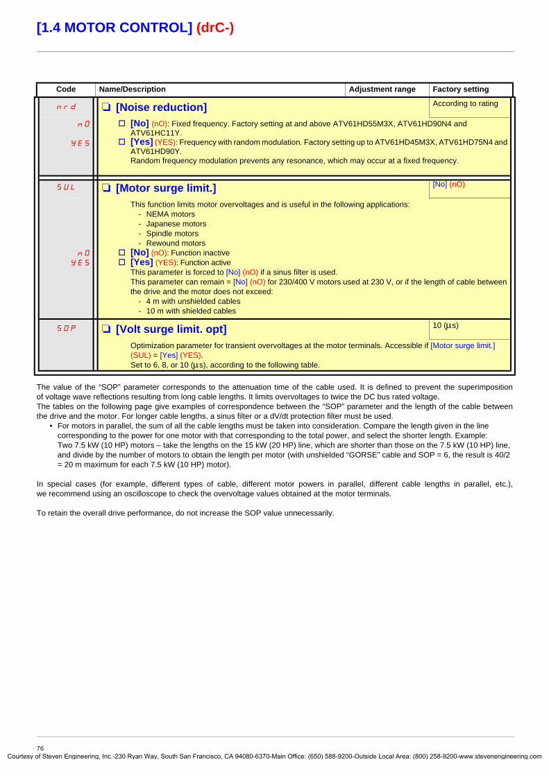
Courtes
[1.4 MOTOR CONTROL] (drC-)
The value of the “SOP” parameter corresponds to the attenuation time of the cable used. It is defined to prevent the superimposition of voltage wave reflections resulting from long cable lengths. It limits overvoltages to twice the DC bus rated voltage.The tables on the following page give examples of correspondence between the “SOP” parameter and the length of the cable between the drive and the motor. For longer cable lengths, a sinus filter or a dV/dt protection filter must be used.
• For motors in parallel, the sum of all the cable lengths must be taken into consideration. Compare the length given in the line corresponding to the power for one motor with that corresponding to the total power, and select the shorter length. Example: Two 7.5 kW (10 HP) motors – take the lengths on the 15 kW (20 HP) line, which are shorter than those on the 7.5 kW (10 HP) line, and divide by the number of motors to obtain the length per motor (with unshielded “GORSE” cable and SOP = 6, the result is 40/2 = 20 m maximum for each 7.5 kW (10 HP) motor).
In special cases (for example, different types of cable, different motor powers in parallel, different cable lengths in parallel, etc.), we recommend using an oscilloscope to check the overvoltage values obtained at the motor terminals.
To retain the overall drive performance, do not increase the SOP value unnecessarily.
Code Name/Description Adjustment range Factory setting
nrd M [Noise reduction] According to rating
nO
YES
v [No] (nO): Fixed frequency. Factory setting at and above ATV61HD55M3X, ATV61HD90N4 and ATV61HC11Y.
v [Yes] (YES): Frequency with random modulation. Factory setting up to ATV61HD45M3X, ATV61HD75N4 and ATV61HD90Y.Random frequency modulation prevents any resonance, which may occur at a fixed frequency.
SUL M [Motor surge limit.] [No] (nO)
nO
YES
This function limits motor overvoltages and is useful in the following applications:- NEMA motors- Japanese motors- Spindle motors- Rewound motors
v [No] (nO): Function inactivev [Yes] (YES): Function active
This parameter is forced to [No] (nO) if a sinus filter is used.This parameter can remain = [No] (nO) for 230/400 V motors used at 230 V, or if the length of cable between the drive and the motor does not exceed:
- 4 m with unshielded cables- 10 m with shielded cables
SOP M [Volt surge limit. opt] 10 (μs)
Optimization parameter for transient overvoltages at the motor terminals. Accessible if [Motor surge limit.] (SUL) = [Yes] (YES).Set to 6, 8, or 10 (μs), according to the following table.
76y of Steven Engineering, Inc.-230 Ryan Way, South San Francisco, CA 94080-6370-Main Office: (650) 588-9200-Outside Local Area: (800) 258-9200-www.stevenengineering.com
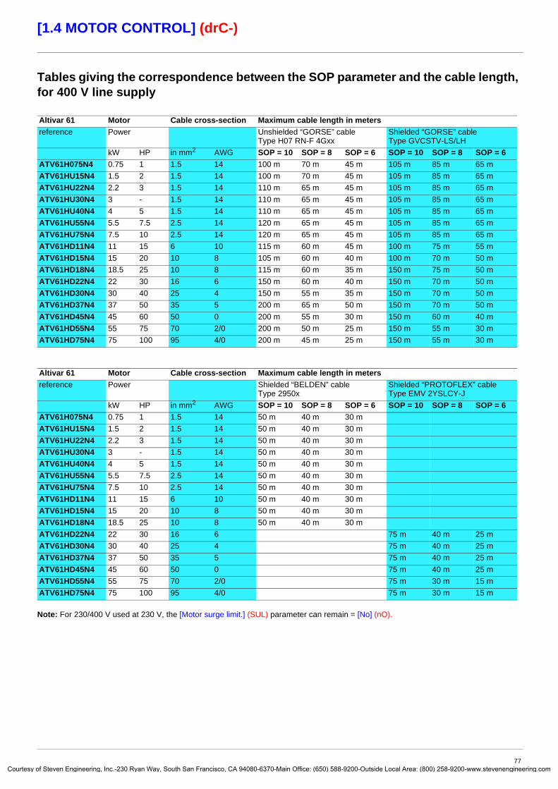
Courtes
[1.4 MOTOR CONTROL] (drC-)
Tables giving the correspondence between the SOP parameter and the cable length, for 400 V line supply
Note: For 230/400 V used at 230 V, the [Motor surge limit.] (SUL) parameter can remain = [No] (nO).
Altivar 61 Motor Cable cross-section Maximum cable length in metersreference Power Unshielded “GORSE” cable
Type H07 RN-F 4GxxShielded “GORSE” cableType GVCSTV-LS/LH
kW HP in mm2 AWG SOP = 10 SOP = 8 SOP = 6 SOP = 10 SOP = 8 SOP = 6ATV61H075N4 0.75 1 1.5 14 100 m 70 m 45 m 105 m 85 m 65 mATV61HU15N4 1.5 2 1.5 14 100 m 70 m 45 m 105 m 85 m 65 mATV61HU22N4 2.2 3 1.5 14 110 m 65 m 45 m 105 m 85 m 65 mATV61HU30N4 3 - 1.5 14 110 m 65 m 45 m 105 m 85 m 65 mATV61HU40N4 4 5 1.5 14 110 m 65 m 45 m 105 m 85 m 65 mATV61HU55N4 5.5 7.5 2.5 14 120 m 65 m 45 m 105 m 85 m 65 mATV61HU75N4 7.5 10 2.5 14 120 m 65 m 45 m 105 m 85 m 65 mATV61HD11N4 11 15 6 10 115 m 60 m 45 m 100 m 75 m 55 mATV61HD15N4 15 20 10 8 105 m 60 m 40 m 100 m 70 m 50 mATV61HD18N4 18.5 25 10 8 115 m 60 m 35 m 150 m 75 m 50 mATV61HD22N4 22 30 16 6 150 m 60 m 40 m 150 m 70 m 50 mATV61HD30N4 30 40 25 4 150 m 55 m 35 m 150 m 70 m 50 mATV61HD37N4 37 50 35 5 200 m 65 m 50 m 150 m 70 m 50 mATV61HD45N4 45 60 50 0 200 m 55 m 30 m 150 m 60 m 40 mATV61HD55N4 55 75 70 2/0 200 m 50 m 25 m 150 m 55 m 30 mATV61HD75N4 75 100 95 4/0 200 m 45 m 25 m 150 m 55 m 30 m
Altivar 61 Motor Cable cross-section Maximum cable length in metersreference Power Shielded “BELDEN” cable
Type 2950xShielded “PROTOFLEX” cableType EMV 2YSLCY-J
kW HP in mm2 AWG SOP = 10 SOP = 8 SOP = 6 SOP = 10 SOP = 8 SOP = 6ATV61H075N4 0.75 1 1.5 14 50 m 40 m 30 mATV61HU15N4 1.5 2 1.5 14 50 m 40 m 30 mATV61HU22N4 2.2 3 1.5 14 50 m 40 m 30 mATV61HU30N4 3 - 1.5 14 50 m 40 m 30 mATV61HU40N4 4 5 1.5 14 50 m 40 m 30 mATV61HU55N4 5.5 7.5 2.5 14 50 m 40 m 30 mATV61HU75N4 7.5 10 2.5 14 50 m 40 m 30 mATV61HD11N4 11 15 6 10 50 m 40 m 30 mATV61HD15N4 15 20 10 8 50 m 40 m 30 mATV61HD18N4 18.5 25 10 8 50 m 40 m 30 mATV61HD22N4 22 30 16 6 75 m 40 m 25 mATV61HD30N4 30 40 25 4 75 m 40 m 25 mATV61HD37N4 37 50 35 5 75 m 40 m 25 mATV61HD45N4 45 60 50 0 75 m 40 m 25 mATV61HD55N4 55 75 70 2/0 75 m 30 m 15 mATV61HD75N4 75 100 95 4/0 75 m 30 m 15 m
77y of Steven Engineering, Inc.-230 Ryan Way, South San Francisco, CA 94080-6370-Main Office: (650) 588-9200-Outside Local Area: (800) 258-9200-www.stevenengineering.com

Courtes
[1.4 MOTOR CONTROL] (drC-)
(1)The parameter can also be accessed in the [1.3 SETTINGS] (SEt-) menu.
Code Name/Description Adjustment range Factory setting
Ubr M [Braking level] According to drive voltage rating
DC bus voltage threshold above which the braking transistor cuts in to limit this voltage.ATV61ppppM3p: factory setting 395 V.ATV61ppppN4: factory setting 785 V.ATV61ppppY: factory setting 1127 V or 1080 V according to rating.The adjustment range depends on the voltage rating of the drive and the [Mains voltage] (UrES) parameter, page 196.
bbA M [Braking balance] [No] (nO)
nO
YES
v [No] (nO): Function inactivev [Yes] (YES): Function active, to be used on drives connected in parallel via their DC bus. Used to balance the
braking power between the drives. The [Braking level] (Ubr) parameter, page 78, must be set to the same value on the various drives.The value [Yes] (YES) is only possible if [Dec ramp adapt.] (brA) = [No] (nO) (see page 132).
Parameter that can be modified during operation or when stopped.
78y of Steven Engineering, Inc.-230 Ryan Way, South San Francisco, CA 94080-6370-Main Office: (650) 588-9200-Outside Local Area: (800) 258-9200-www.stevenengineering.com

Courtes
[1.5 INPUTS / OUTPUTS CFG] (I-O-)
With graphic display terminal:
With integrated display terminal:
RDY Term +0.00 Hz REMMAIN MENU
1 DRIVE MENU2 ACCESS LEVEL3 OPEN / SAVE AS4 PASSWORD5 LANGUAGE
Code T/K
ENT
RDY Term +0.00 Hz REM1 DRIVE MENU
1.1 SIMPLY START1.2 MONITORING1.3 SETTINGS1.4 MOTOR CONTROL1.5 INPUTS / OUTPUTS CFG
Code << >> T/K
ENTRUN Term +0.00 Hz REM
1.5 INPUTS / OUTPUTS CFG2/3 wire control2 wire typeReverse assign.LI1 CONFIGURATIONLIx CONFIGURATION
Code << >> T/K
XXX
CtL-
SIM-
I-O-
ESC
ESC
ESC
ESC
ENT
ENT
ESC
LAC-
Displays the drive state
INPUTS / OUTPUTS CFG
Power-up
79y of Steven Engineering, Inc.-230 Ryan Way, South San Francisco, CA 94080-6370-Main Office: (650) 588-9200-Outside Local Area: (800) 258-9200-www.stevenengineering.com

Courtes
[1.5 INPUTS / OUTPUTS CFG] (I-O-)
The parameters in the [1.5 INPUTS / OUTPUTS CFG] (I-O-) menu can only be modified when the drive is stopped and no run command is present.
Code Name/Description Adjustment range Factory setting
tCC M [2/3 wire control] [2 wire] (2C)
2C
3C
v [2 wire] (2C) v [3 wire] (3C)
2-wire control: This is the input state (0 or 1) or edge (0 to 1 or 1 to 0), which controls running or stopping.
Example of “source” wiring: LI1: forward LIx: reverse
3-wire control (pulse control): A “forward” or “reverse” pulse is sufficient to command starting, a “stop” pulse is sufficient to command stopping. Example of “source” wiring:
LI1: stop LI2: forward LIx: reverse
tCt M [2 wire type] [Transition] (trn)
LEL
trn
PFO
v [Level] (LEL): State 0 or 1 is taken into account for run (1) or stop (0).v [Transition] (trn): A change of state (transition or edge) is necessary to initiate operation, in order to prevent
accidental restarts after a break in the power supply.v [Fwd priority] (PFO): State 0 or 1 is taken into account for run or stop, but the “forward” input always takes
priority over the “reverse” input.
rrS M [Reverse assign.] [No] (nO)
nO
LI1
-
-
C101
-
-
-
Cd00
-
v [No] (nO): Not assignedv [LI1] (LI1) to [LI6] (LI6) v [LI7] (LI7) to [LI10] (LI10): If VW3A3201 logic I/O card has been insertedv [LI11] (LI11) to [LI14] (LI14): If VW3A3202 extended I/O card has been insertedv [C101] (C101) to [C115] (C115): With integrated Modbus in [I/O profile] (IO)v [C201] (C201) to [C215] (C215): With integrated CANopen in [I/O profile] (IO)v [C301] (C301) to [C315] (C315): With a communication card in [I/O profile] (IO)v [C401] (C401) to [C415] (C415): With a Controller Inside card in [I/O profile] (IO)v [CD00] (Cd00) to [CD13] (Cd13): In [I/O profile] (IO) can be switched with possible logic inputsv [CD14] (Cd14) to [CD15] (Cd15): In [I/O profile] (IO) can be switched without logic inputs
Assignment of the reverse direction command.
+24 LI1 LIxATV 71
+24 LI1 LI2 LIxATV 71
WARNINGUNINTENDED EQUIPMENT OPERATIONTo change the assignment of [2/3 wire control] (tCC) press the “ENT” key for 2 s.It causes the following functions to return to factory setting: [2 wire type] (tCt) and [Reverse assign.] (rrS) below, and all functions which assign logic inputs and analog inputs. The macro configuration selected will also be reset if it has been customized (loss of custom settings).It is advisable to configure this parameter before configuring the [1.6 COMMAND] (CtL-) and [1.7 APPLICATION FUNCT.] (FUn-) menus.Check that this change is compatible with the wiring diagram used.Failure to follow these instructions can result in death or serious injury.
80y of Steven Engineering, Inc.-230 Ryan Way, South San Francisco, CA 94080-6370-Main Office: (650) 588-9200-Outside Local Area: (800) 258-9200-www.stevenengineering.com

Courtes
[1.5 INPUTS / OUTPUTS CFG] (I-O-)
Code Name/Description Adjustment range Factory setting
L1- b [LI1 CONFIGURATION] L1A M [LI1 assignment]
Read-only parameter, cannot be configured.It displays all the functions that are assigned to input LI1 in order to check multiple assignments.
L1d M [LI1 On Delay] 0 to 200 ms 0
This parameter is used to take account of the change of the logic input to state 1 with a delay that can be adjusted between 0 and 200 milliseconds, in order to filter out possible interference. The change to state 0 is taken into account without delay.
L-- b [LIx CONFIGURATION]All the logic inputs available on the drive are processed as in the example for LI1 above, up to LI6, LI10 or LI14, depending on whether or not option cards have been inserted.
WARNINGUNINTENDED EQUIPMENT OPERATIONCheck that the delay set does not pose a risk or lead to undesired operation.The relative order in which these inputs are taken into account may be modified according to the delay values of the various logic inputs, and thus lead to unintended operation.Failure to follow these instructions can result in death or serious injury.
81y of Steven Engineering, Inc.-230 Ryan Way, South San Francisco, CA 94080-6370-Main Office: (650) 588-9200-Outside Local Area: (800) 258-9200-www.stevenengineering.com

Courtes
[1.5 INPUTS / OUTPUTS CFG] (I-O-)
Configuration of analog inputs and Pulse inputThe minimum and maximum input values (in volts, mA, etc.) are converted to% in order to adapt the references to the application.
Minimum and maximum input values:The minimum value corresponds to a reference of 0% and the maximum value to a reference of 100%. The minimum value may be greater than the maximum value:
For +/- bidirectional inputs, the min. and max. are relative to the absolute value, for example, +/- 2 to 8 V.
Negative min. value of Pulse input:
Range (output values): For analog inputs onlyThis parameter is used to configure the reference range to [0% V 100%] or [-100% V +100%] in order to obtain a bidirectional output from a unidirectional input.
Reference
100%
0%[Min value]
(CrLx or ULx or PIL)
[Max value](CrHx or
UHx or PFr)
20 mA or 10 V or
30.00 kHz
Reference
100%
0%[Min value]
(CrLx or ULx or PIL)
[Max value](CrHx or
UHx or PFr)
Current or voltage or frequency input
Current or voltage or frequency input
20 mA or 10 V or
30.00 kHz
Reference
100%
0%[RP min value] (PIL)
[RP max value](PFr)
30.00kHz
Frequency input-30.00
kHz
Reference
100%
0%[Min value] [Max value]
Range 0 V 100%
Reference
100%
0%[Min value]
[Max value]
Current or voltage input
Current or voltage input
-100%
Range -100% V +100%
20 mAor 10 V
20 mAor 10 V
82y of Steven Engineering, Inc.-230 Ryan Way, South San Francisco, CA 94080-6370-Main Office: (650) 588-9200-Outside Local Area: (800) 258-9200-www.stevenengineering.com

Courtes
[1.5 INPUTS / OUTPUTS CFG] (I-O-)
Code Name/Description Adjustment range Factory setting
bSP M [Reference template] [Standard] (bSd)
bSd
bLS
bnS
bnS0
v [Standard] (bSd)At zero reference the frequency = LSP
v [Pedestal] (bLS) At reference = 0 to LSP the frequency = LSP
v [Deadband] (bnS) At reference = 0 to LSP the frequency = 0
v [Deadband 0] (bnS0)This operation is the same as [Standard] (bSd), except that in the following cases at zero reference, the frequency = 0:• The signal is less than [Min value], which is greater than 0 (example 1 V on a 2 - 10 V input)• The signal is greater than [Min value], which is greater than [Max value] (example 11 V on a 10 - 0 V input).
If the input range is configured as “bidirectional”, operation remains identical to [Standard] (bSd).
This parameter defines how the speed reference is taken into account, for analog inputs and Pulse input only. In the case of the PID regulator, this is the PID output reference.The limits are set by the [Low speed] (LSP) and [High speed] (HSP) parameters, page 37
Frequency
reference
LSP
-100%
+100%
HSP
LSP
HSP
0%
Frequency
referenceLSP-100%
+100%
HSP
LSP
HSP
Frequency
referenceLSP-100%
+100%
HSP
LSP
HSP
0
Frequency
reference
LSP-100%
+100%
HSP
LSP
HSP
0%
83y of Steven Engineering, Inc.-230 Ryan Way, South San Francisco, CA 94080-6370-Main Office: (650) 588-9200-Outside Local Area: (800) 258-9200-www.stevenengineering.com

Courtes
[1.5 INPUTS / OUTPUTS CFG] (I-O-)
Delinearization: For analog inputs onlyThe input can be delinearized by configuring an intermediate point on the input/output curve of this input:
For range 0 V 100%
Note: For [Interm. point X], 0% corresponds to [Min value] and 100% to [Max value]
For range -100% V 100%
reference
100%
0%
[Min value](0%)
[Interm. point X]
[Max value](100%)
current or voltage input
[Interm. point Y]
20 mAor 10 V
reference
100%
0%
[Min value](- 100%)
[Interm. point X]
[Max value](100%)
current or voltage input
[Interm. point Y]
- [Interm. point Y]
- 100%
- [Interm. point X]
0% 20 mAor 10 V
84y of Steven Engineering, Inc.-230 Ryan Way, South San Francisco, CA 94080-6370-Main Office: (650) 588-9200-Outside Local Area: (800) 258-9200-www.stevenengineering.com

Courtes
[1.5 INPUTS / OUTPUTS CFG] (I-O-)
Code Name/Description Adjustment range Factory setting
AI1�- b [AI1 CONFIGURATION] AI1A M [AI1 assignment]
Read-only parameter, cannot be configured.It displays all the functions associated with input AI1 in order to check, for example, for compatibility problems.
AI1t M [AI1 Type] [Voltage] (10U)
10U
n10U
v [Voltage] (10U): Positive voltage input (negative values are considered as zero: the input is unidirectional).v [Voltage +/-] (n10U): Positive and negative voltage input (the input is bidirectional).
UIL1 M [AI1 min value] 0 to 10.0 V 0 V
UIH1 M [AI1 max value] 0 to 10.0 V 10.0 V
AI1F M [AI1 filter] 0 to 10.00 s 0 s
Interference filtering.
AI1E M [AI1 Interm. point X] 0 to 100% 0%
Input delinearization point coordinate.• 0% corresponds to [AI1 min value] (UIL1).• 100% corresponds to [AI1 max value] (UIH1).
AI1S M [AI1 Interm. point Y] 0 to 100% 0%
Output delinearization point coordinate (frequency reference).
85y of Steven Engineering, Inc.-230 Ryan Way, South San Francisco, CA 94080-6370-Main Office: (650) 588-9200-Outside Local Area: (800) 258-9200-www.stevenengineering.com

Courtes
[1.5 INPUTS / OUTPUTS CFG] (I-O-)
Code Name/Description Adjustment range Factory setting
AI2- b [AI2 CONFIGURATION] AI2A M [AI2 assignment]
Read-only parameter, cannot be configured.It displays all the functions associated with input AI2 in order to check, for example, for compatibility problems.
AI2t M [AI2 Type] [Current] (0 A)
10U
0A
v [Voltage] (10U): Voltage inputv [Current] (0 A): Current input
CrL2 M [AI2 min. value] 0 to 20.0 mA 0 mA
The parameter can be accessed if [AI2 Type] (AI2t) = [Current] (0 A)
UIL2 M [AI2 min. value] 0 to 10.0 V 0 V
The parameter can be accessed if [AI2 Type] (AI2t) = [Voltage] (10U)
CrH2 M [AI2 max. value] 0 to 20.0 mA 20.0 mA
The parameter can be accessed if [AI2 Type] (AI2t) = [Current] (0 A)
UIH2 M [AI2 max. value] 0 to 10.0 V 10.0 V
The parameter can be accessed if [AI2 Type] (AI2t) = [Voltage] (10U)
AI2F M [AI2 filter] 0 to 10.00 s 0 s
Interference filtering.
AI2L M [AI2 range] [0 – 100%] (POS)
POS
nEG
v [0 – 100%] (POS): Unidirectional inputv [+/- 100%] (nEG): Bidirectional input
Example: On a 0/10 V input- 0 V corresponds to reference -100%- 5 V corresponds to reference 0%- 10 V corresponds to reference +100%
AI2E M [AI2 Interm. point X] 0 to 100% 0%
Input delinearization point coordinate.• 0% corresponds to [Min value] if the range is 0 V 100%.
• 0% corresponds to if the range is -100% V +100%.
• 100% corresponds to [Max value].
AI2S M [AI2 Interm. point Y] 0 to 100% 0%
Output delinearization point coordinate (frequency reference).
[Max value] + [Min value] 2
86y of Steven Engineering, Inc.-230 Ryan Way, South San Francisco, CA 94080-6370-Main Office: (650) 588-9200-Outside Local Area: (800) 258-9200-www.stevenengineering.com

Courtes
[1.5 INPUTS / OUTPUTS CFG] (I-O-)
Code Name/Description Adjustment range Factory setting
AI3- b [AI3 CONFIGURATION] Can be accessed if a VW3A3202 option card has been inserted
AI3A M [AI3 assignment]Read-only parameter, cannot be configured.It displays all the functions associated with input AI3 in order to check, for example, for compatibility problems.
AI3t M [AI3 Type] [Current] (0 A)
0A
Read-only parameter, cannot be configured.v [Current] (0 A): Current input
CrL3 M [AI3 min. value] 0 to 20.0 mA 0 mA
CrH3 M [AI3 max. value] 0 to 20.0 mA 20.0 mA
AI3F M [AI3 filter] 0 to 10.00 s 0 s
Interference filtering.
AI3L M [AI3 range] [0 – 100%] (POS)
POS
nEG
v [0 – 100%] (POS): Unidirectional inputv [+/- 100%] (nEG): Bidirectional input
Example: On a 4 – 20 mA input- 4 mA corresponds to reference -100%- 12 mA corresponds to reference 0%- 20 mA corresponds to reference +100%
Since AI3 is, in physical terms, a bidirectional input, the [+/- 100%] (nEG) configuration must only be used if the signal applied is unidirectional. A bidirectional signal is not compatible with a bidirectional configuration.
AI3E M [AI3 Interm. point X] 0 to 100% 0%
Input delinearization point coordinate.• 0% corresponds to [Min value] (CrL3) if the range is 0 V 100%.
• 0% corresponds to if the range is -100% V +100%.
• 100% corresponds to [AI3 max. value] (CrH3).
AI3S M [AI3 Interm. point Y] 0 to 100% 0%
Output delinearization point coordinate (frequency reference).
[AI3 max. value] (CrH3) - [AI3 min. value] (CrL3)2
87y of Steven Engineering, Inc.-230 Ryan Way, South San Francisco, CA 94080-6370-Main Office: (650) 588-9200-Outside Local Area: (800) 258-9200-www.stevenengineering.com

Courtes
[1.5 INPUTS / OUTPUTS CFG] (I-O-)
Code Name/Description Adjustment range Factory setting
AI4- b [AI4 CONFIGURATION] Can be accessed if a VW3A3202 option card has been inserted
AI4A M [AI4 assignment]Read-only parameter, cannot be configured.It displays all the functions associated with input AI4 in order to check, for example, for compatibility problems.
AI4t M [AI4 Type] [Voltage] (10U)
10U
0A
v [Voltage] (10U): Voltage inputv [Current] (0 A): Current input
CrL4 M [AI4 min value] 0 to 20.0 mA 0 mA
The parameter can be accessed if [AI4 Type] (AI4t) = [Current] (0 A)
UIL4 M [AI4 min value] 0 to 10.0 V 0 V
The parameter can be accessed if [AI4 Type] (AI4t) = [Voltage] (10U)
CrH4 M [AI4 max value] 0 to 20.0 mA 20.0 mA
The parameter can be accessed if [AI4 Type] (AI4t) = [Current] (0 A)
UIH4 M [AI4 max value] 0 to 10.0 V 10.0 V
The parameter can be accessed if [AI4 Type] (AI4t) = [Voltage] (10U)
AI4F M [AI4 filter] 0 to 10.00 s 0 s
Interference filtering.
AI4L M [AI4 range] [0 – 100%] (POS)
POS
nEG
v [0 – 100%] (POS): Unidirectional inputv [+/- 100%] (nEG): Bidirectional input
Example: On a 0/10 V input- 0 V corresponds to reference -100%- 5 V corresponds to reference 0%- 10 V corresponds to reference +100%
AI4E M [AI4 Interm.point X] 0 to 100% 0%
Input delinearization point coordinate.• 0% corresponds to [Min value] if the range is 0 V 100%.
• 0% corresponds to if the range is -100% V + 100%.
• 100% corresponds to [Max value].
AI4S M [AI4 Interm.point Y] 0 to 100% 0%
Output delinearization point coordinate (frequency reference).
[Max value] + [Min value]2
88y of Steven Engineering, Inc.-230 Ryan Way, South San Francisco, CA 94080-6370-Main Office: (650) 588-9200-Outside Local Area: (800) 258-9200-www.stevenengineering.com

Courtes
[1.5 INPUTS / OUTPUTS CFG] (I-O-)
Code Name/Description Adjustment range Factory setting
AU1- b [VIRTUAL AI1] AIC1 M [AI net. channel] [No] (nO)
nO
Mdb
CAn
nEt
APP
Virtual input.This parameter can also be accessed in the [PID REGULATOR] (PId-) submenu, page 151. [Non] (nO): Not assigned (in this case, the virtual input does not appear in the analog input assignment parameters for the functions)
v [Modbus] (Mdb): Integrated Modbusv [CANopen] (CAn): Integrated CANopenv [Com. card] (nEt): Communication card (if inserted)v [C.Insid. card] (APP): Controller Inside card (if inserted)
Scale: The value 8192 transmitted by this input is equivalent to 10 V on a 10 V input.
WARNINGUNINTENDED EQUIPMENT OPERATIONIf the equipment switches to forced local mode (see page 214), the virtual input remains frozen at the last value transmitted.Do not use the virtual input and forced local mode in the same configuration.Failure to follow this instruction can result in death or serious injury.
89y of Steven Engineering, Inc.-230 Ryan Way, South San Francisco, CA 94080-6370-Main Office: (650) 588-9200-Outside Local Area: (800) 258-9200-www.stevenengineering.com
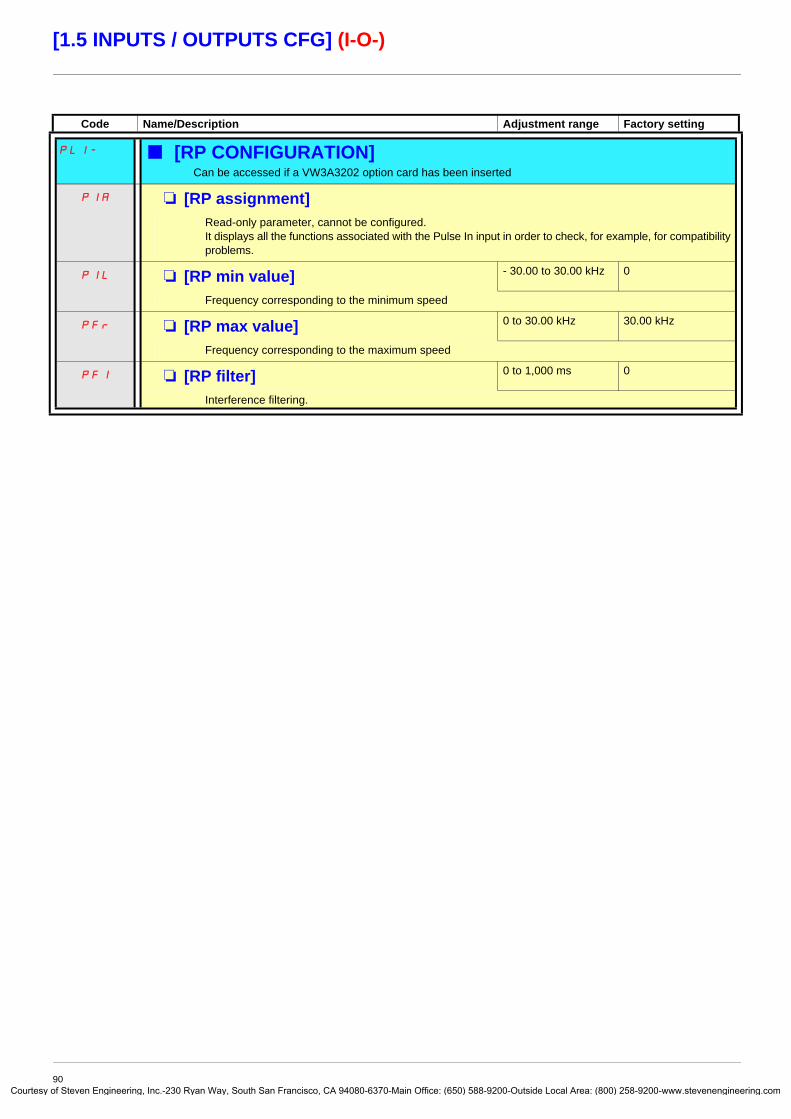
Courtes
[1.5 INPUTS / OUTPUTS CFG] (I-O-)
Code Name/Description Adjustment range Factory setting
PLI- b [RP CONFIGURATION] Can be accessed if a VW3A3202 option card has been inserted
PIA M [RP assignment]Read-only parameter, cannot be configured.It displays all the functions associated with the Pulse In input in order to check, for example, for compatibility problems.
PIL M [RP min value] - 30.00 to 30.00 kHz 0
Frequency corresponding to the minimum speed
PFr M [RP max value] 0 to 30.00 kHz 30.00 kHz
Frequency corresponding to the maximum speed
PFI M [RP filter] 0 to 1,000 ms 0
Interference filtering.
90y of Steven Engineering, Inc.-230 Ryan Way, South San Francisco, CA 94080-6370-Main Office: (650) 588-9200-Outside Local Area: (800) 258-9200-www.stevenengineering.com

Courtes
[1.5 INPUTS / OUTPUTS CFG] (I-O-)
Configuration of the encoder input serving as a reference, with a frequency generatorThis reference is not signed, therefore the directions of operation must be given via the control channel (logic inputs, for example).
Minimum and maximum values (input values):The minimum value corresponds to a minimum reference of 0% and the maximum value to a maximum reference of 100%. The minimum value may be greater than the maximum value. It may also be negative.
A reference can be obtained at zero frequency by assigning a negative value to the minimum value.
Reference
100%
0[Freq. min.
value](EIL)
[Freq. max. value](EFr)
300 kHz
Reference
100%
0[Freq. min.
value](EIL)
[Freq. max. value](EFr)
Frequency input
Frequency input
300 kHz
Reference
100%
[Freq. min. value](EIL)
[Freq. max. value](EFr)
300 kHzFrequency input0
91y of Steven Engineering, Inc.-230 Ryan Way, South San Francisco, CA 94080-6370-Main Office: (650) 588-9200-Outside Local Area: (800) 258-9200-www.stevenengineering.com

Courtes
[1.5 INPUTS / OUTPUTS CFG] (I-O-)
The encoder configuration can also be accessed in the [1.4 MOTOR CONTROL] (drC-) menu.
Code Name/Description Adjustment range Factory setting
IEn- b [ENCODER CONFIGURATION] The encoder parameters can only be accessed if the encoder card has been inserted, and the available selections will depend on the type of encoder card used.
EnS M [Encoder type] [AABB] (AAbb)
AAbb
Ab
A
The parameter can be accessed if an encoder card has been inserted.To be configured in accordance with the type of encoder used.
v [AABB] (AAbb): For signals A, A-, B, B-.v [AB] (Ab): For signals A, B.v [A] (A): For signal A. Value cannot be accessed if [Encoder usage] (EnU) page 93 = [Spd fdk reg.] (rEG).
EnC M [Encoder check] [Not done] (nO)
nO
YES
dOnE
Encoder feedback check See procedure page 74.The parameter can be accessed if an encoder card has been inserted and if [Encoder usage] (EnU) page 93 is not [Speed ref.] (PGr).
v [Not done] (nO) Check not performed.v [Yes] (YES): Activates monitoring of the encoder.v [Done] (dOnE): Check performed successfully.
The check procedure checks:- The direction of rotation of the encoder/motor- The presence of signals (wiring continuity)- The number of pulses/revolution
If a fault is detected, the drive locks in [Encoder fault] (EnF) fault mode.
92y of Steven Engineering, Inc.-230 Ryan Way, South San Francisco, CA 94080-6370-Main Office: (650) 588-9200-Outside Local Area: (800) 258-9200-www.stevenengineering.com

Courtes
[1.5 INPUTS / OUTPUTS CFG] (I-O-)
Code Name/Description Adjustment range Factory setting
b [ENCODER CONFIGURATION] (continued)
EnU M [Encoder usage] [No] (nO)
nO
SEC
rEG
PGr
The parameter can be accessed if an encoder card has been inserted.v [No] (nO): Function inactive, In this case, the other parameters cannot be accessed.v [Fdbk monit.] (SEC): The encoder provides speed feedback for monitoring only.v [Spd fdk reg.] (rEG): The encoder provides speed feedback for regulation and monitoring.
If [Motor control type] (Ctt) = [SVC U] (UUC) the encoder operates in speed feedback mode and enables static correction of the speed to be performed. This configuration is not accessible for other [Motor control type] (Ctt) values.
v [Speed ref.] (PGr): The encoder provides a reference.
PGI M [Number of pulses] 100 to 5,000 1,024
Number of pulses per encoder revolution.The parameter can be accessed if an encoder card has been inserted.
PGA M [Reference type] [Encoder] (EnC)
EnC
PtG
The parameter can be accessed if [Encoder usage] (EnU) = [Speed ref.] (PGr).v [Encoder] (EnC): Use of an encoder.v [Freq. gen.] (PtG): Use of a frequency generator (unsigned reference).
EIL M [Freq. min. value] - 300 to 300 kHz 0
The parameter can be accessed if [Encoder usage] (EnU) = [Speed ref.] (PGr) and if [Reference type] (PGA) = [Freq. gen.] (PtG).Frequency corresponding to the minimum speed
EFr M [Freq. max value] 0.00 to 300 kHz 300 kHz
The parameter can be accessed if [Encoder usage] (EnU) = [Speed ref.] (PGr) and if [Reference type] (PGA) = [Freq. gen.] (PtG).Frequency corresponding to the maximum speed
EFI M [Freq. signal filter] 0 to 1,000 ms 0
The parameter can be accessed if [Encoder usage] (EnU) = [Speed ref.] (PGr).Interference filtering.
93y of Steven Engineering, Inc.-230 Ryan Way, South San Francisco, CA 94080-6370-Main Office: (650) 588-9200-Outside Local Area: (800) 258-9200-www.stevenengineering.com

Courtes
[1.5 INPUTS / OUTPUTS CFG] (I-O-)
Code Name/Description Adjustment range Factory setting
r1- b [R1 CONFIGURATION] r1 M [R1 Assignment] [No drive flt] (FLt)
nO
FLt
rUn
FtA
FLA
CtA
SrA
tSA
PEE
PFA
AP2
F2A
tAd
ttHA
ttLA
MFrd
MrrS
rtAH
rtAL
FtAL
F2AL
CtAL
ULA
OLA
PFAH
PFAL
PISH
Ern
tS2
tS3
bMP
v [No] (nO): Not assignedv [No drive flt] (FLt): Drive not faulty (relay normally energized, and de-energized if there is a fault)v [Drv running] (rUn): Drive runningv [Freq. Th. attain.] (FtA): The relay is closed if the frequency is greater than [Freq. threshold] (Ftd)
page 59.v [HSP attain.] (FLA): High speed reachedv [Current Th. attained] (CtA): The relay is closed if the current is greater than [Current threshold] (Ctd) page 59.v [Freq.ref.att] (SrA): Frequency reference reachedv [Th.mot. att.] (tSA): Motor 1 thermal state reachedv [PID error al] (PEE): PID error alarmv [PID fdbk al.] (PFA): PID feedback alarm (greater than [Max fbk alarm] (PAH) page 152 or less than
[Min fbk alarm] (PAL) page 152)v [AI2 Al. 4-20] (AP2): Alarm indicating absence of 4-20 mA signal on input AI2v [Freq. Th. 2 attain.] (F2A): The relay is closed if the frequency is greater than [Freq. threshold 2] (F2d) page 59.v [Th.drv.att.] (tAd): Drive thermal state reachedv [High tq. att.] (ttHA): Motor torque greater than high threshold [High torque thd.] (ttH) page 59v [Low tq. att.] (ttLA): Motor torque less than low threshold [Low torque thd.] (ttL) page 59v [Forward] (MFrd): Motor running forwardv [Reverse] (MrrS): Motor running in reversev [High Reference Att.] (rtAH): The relay is closed if the frequency reference is greater than [High Freq.
Ref. Thr.] (rtd) page 60.v [Low Reference Att.] (rtAL): The relay is closed if the frequency reference is less than [Low Freq. Ref.
Thr.] (rtdL) page 60.v [Low Frq. Th. Attain.] (FtAL): The relay is closed if the frequency is less than [Low Freq.Threshold]
(FtdL) page 59.v [2Low F.Thld] (F2AL): The relay is closed if the frequency is less than [2 Freq. Threshold] (F2dL)
page 59.v [Low I Th.At.] (CtAL): The relay is closed if the current is less than [Low I Threshold] (CtdL) page 59.v [Pro.Undload] (ULA): Process underload (see page 206)v [Ovld.P.Alrm] (OLA): Process overload (see page 208)v [PID high Al.] (PFAH): PID feedback alarm (greater than [Max fbk alarm] (PAH) page 152).v [PID low Alarm] (PFAL): PID feedback alarm (less than [Min fbk alarm] (PAL) page 152).v [Regul.Alarm] (PISH): PID regulator feedback supervision fault page 155.v [Emerg. Run] (Ern): The relay is closed if the drive is in emergency run. See [Forced Run] (InHS)
page 199.v [Th.mot2 att.] (tS2): Motor 2 thermal state reachedv [Th.mot3 att] (tS3): Motor 3 thermal state reachedv [Rem.Cmd] (bMP): Control via the graphic display terminal is activated via a function key on the terminal.
94y of Steven Engineering, Inc.-230 Ryan Way, South San Francisco, CA 94080-6370-Main Office: (650) 588-9200-Outside Local Area: (800) 258-9200-www.stevenengineering.com

Courtes
[1.5 INPUTS / OUTPUTS CFG] (I-O-)
Code Name/Description Adjustment range Factory setting
r1- b [R1 CONFIGURATION] (continued)
r1 M [R1 Assignment] (continued)
AtS
CnF0
CnF1
CnF2
CFP1
CFP2
CFP3
dbL
brS
PrM
FqLA
MCP
AG1
AG2
AG3
P1A
P2A
PLA
EFA
USA
UPA
tHA
SSA
tJA
bOA
APA
AP3
AP4
FSA
rdY
v [Neg Torque] (AtS): Negative torque (braking)v [Cnfg.0 act.] (CnF0): Configuration 0 activev [Cnfg.1 act.] (CnF1): Configuration 1 activev [Cnfg.2 act.] (CnF2): Configuration 2 activev [Set 1 active] (CFP1): Parameter set 1 activev [Set 2 active] (CFP2): Parameter set 2 activev [Set 3 active] (CFP3): Parameter set 3 activev [DC charged] (dbL): DC bus loadingv [In braking] (brS): Drive brakingv [P. removed] (PRM): Drive locked by “Power removal” inputv [Fr.met. alar.] (FqLA): Measured speed threshold attained: [Pulse warning thd.] (FqL) page 59v [I present] (MCP): Motor current presentv [Alarm Grp 1] (AGI): Alarm group 1v [Alarm Grp 2] (AG2): Alarm group 2v [Alarm Grp 3] (AG3): Alarm group 3v [PTC1 alarm] (P1A): Probe alarm 1v [PTC2 alarm] (P2A): Probe alarm 2v [LI6=PTC al.] (PLA): LI6 = PTC probe alarmsv [Ext. fault al] (EFA): External fault alarmv [Under V. al.] (USA): Undervoltage alarmv [Uvolt warn] (UPA): Undervoltage warningv [Al. °C drv] (tHA): Drive overheatingv [Lim T/I att.] (SSA): Torque limit alarmv [IGBT al.] (tJA): IGBT alarmv [Brake R. al.] (bOA): Braking resistor temperature alarmv [Option al.] (APA): Alarm generated by the Controller Inside cardv [AI3 Al. 4-20] (AP3): Alarm indicating absence of 4-20 mA signal on input AI3v [AI4 Al. 4-20] (AP4): Alarm indicating absence of 4-20 mA signal on input AI4v [Flow Limit.] (FSA): Flow rate limiting active (see page 182)v [Ready] (rdY): Drive ready
95y of Steven Engineering, Inc.-230 Ryan Way, South San Francisco, CA 94080-6370-Main Office: (650) 588-9200-Outside Local Area: (800) 258-9200-www.stevenengineering.com

Courtes
[1.5 INPUTS / OUTPUTS CFG] (I-O-)
(1) 0 to 9999 ms then 10.00 to 60.00 s on the integrated display terminal.
Code Name/Description Adjustment range Factory setting
b [R1 CONFIGURATION] (continued)
r1d M [R1 Delay time] 0 to 60000 ms (1) 0
The change in state only takes effect once the configured time has elapsed, when the information becomes true.The delay cannot be set for the [No drive flt] (FLt) assignment, and remains at 0.
r1S
POS
nEG
M [R1 Active at] [1] (POS)
Configuration of the operating logic:v [1]: State 1 when the information is truev [0]: State 0 when the information is true
Configuration [1] (POS) cannot be modified for the [No drive flt] (FLt), assignment.
r1H M [R1 Holding time] 0 to 9,999 ms 0
The change in state only takes effect once the configured time has elapsed, when the information becomes false.The holding time cannot be set for the [No drive flt] (FLt) assignment, and remains at 0.
r2- b [R2 CONFIGURATION] r2 M [R2 Assignment] [Drv running] (rUn)
LLC
OCC
dCO
dAM
Identical to R1 (see page 94) with the addition of (shown for information only as these selections can only be configured in the [APPLICATION FUNCT.] (Fun-)) menu:
v [Input cont.] (LLC): Line contactor controlv [Output cont] (OCC): Output contactor controlv [DC charging] (dCO): DC bus precharging contactor controlv [Damper] (dAM): Damper control
r2d M [R2 Delay time] 0 to 60000 ms (1) 0
The delay cannot be set for the [No drive flt] (FLt), [Output cont] (OCC), [DC charging] (dCO), and [Input cont.] (LLC) assignments, and remains at 0. The change in state only takes effect once the configured time has elapsed, when the information becomes true.
r2S
POS
nEG
M [R2 Active at] [1] (POS)
Configuration of the operating logic:v [1]: State 1 when the information is truev [0]: State 0 when the information is true
The [1] (POS) configuration cannot be modified for the[No drive flt] (FLt), [DC charging] (dCO) and [Input cont.] (LLC), assignments.
r2H M [R2 Holding time] 0 to 9,999 ms 0
The holding time cannot be set for the [No drive flt] (FLt), [DC charging] (dCO) and [Input cont.] (LLC) assignments, and remains at 0. The change in state only takes effect once the configured time has elapsed, when the information becomes false.
96y of Steven Engineering, Inc.-230 Ryan Way, South San Francisco, CA 94080-6370-Main Office: (650) 588-9200-Outside Local Area: (800) 258-9200-www.stevenengineering.com

Courtes
[1.5 INPUTS / OUTPUTS CFG] (I-O-)
(1) 0 to 9999 ms then 10.00 to 60.00 s on the integrated display terminal.
Code Name/Description Adjustment range Factory setting
r3- b [R3 CONFIGURATION] Can be accessed if a VW3A3201 option card has been inserted
r3 M [R3 Assignment] [No] (nO)
Identical to R2
r3d M [R3 Delay time] 0 to 60000 ms (1) 0
The delay cannot be set for the [No drive flt] (FLt), [Output cont] (OCC), [DC charging] (dCO), and [Input cont.] (LLC) assignments, and remains at 0. The change in state only takes effect once the configured time has elapsed, when the information becomes true.
r3S
POS
nEG
M [R3 Active at] [1] (POS)
Configuration of the operating logic:v [1]: State 1 when the information is truev [0]: State 0 when the information is true
The [1] (POS) configuration cannot be modified for the[No drive flt] (FLt), [DC charging] (dCO) and [Input cont.] (LLC), assignments.
r3H M [R3 Holding time] 0 to 9,999 ms 0
The holding time cannot be set for the [No drive flt] (FLt), [DC charging] (dCO) and [Input cont.] (LLC) assignments, and remains at 0. The change in state only takes effect once the configured time has elapsed, when the information becomes false.
r4- b [R4 CONFIGURATION] Can be accessed if a VW3A3202 option card has been inserted
r4 M [R4 Assignment] [No] (nO)
Identical to R2 (see page 96).
r4d M [R4 Delay time] 0 to 60000 ms (1) 0
The delay cannot be set for the [No drive flt] (FLt), [Output cont] (OCC), [DC charging] (dCO), and [Input cont.] (LLC) assignments, and remains at 0. The change in state only takes effect once the configured time has elapsed, when the information becomes true.
r4S
POS
nEG
M [R4 Active at] [1] (POS)
Configuration of the operating logic:v [1]: State 1 when the information is truev [0]: State 0 when the information is true
The [1] (POS) configuration cannot be modified for the[No drive flt] (FLt), [DC charging] (dCO) and [Input cont.] (LLC), assignments.
r4H M [R4 Holding time] 0 to 9,999 ms 0
The holding time cannot be set for the [No drive flt] (FLt), [DC charging] (dCO) and [Input cont.] (LLC) assignments, and remains at 0. The change in state only takes effect once the configured time has elapsed, when the information becomes false.
97y of Steven Engineering, Inc.-230 Ryan Way, South San Francisco, CA 94080-6370-Main Office: (650) 588-9200-Outside Local Area: (800) 258-9200-www.stevenengineering.com

Courtes
[1.5 INPUTS / OUTPUTS CFG] (I-O-)
(1) 0 to 9999 ms then 10.00 to 60.00 s on the integrated display terminal.
Code Name/Description Adjustment range Factory setting
LO1- b [LO1 CONFIGURATION] Can be accessed if a VW3A3201 option card has been inserted
LO1 M [LO1 assignment] [No] (nO)
LLC
OCC
dCO
dAM
Identical to R1 (see page 94) with the addition of (shown for information only as these selections can only be configured in the [APPLICATION FUNCT.] (Fun-)) menu:
v [Input cont.] (LLC): Line contactor controlv [Output cont] (OCC): Output contactor controlv [[DC charging] (dCO): DC bus precharging contactor controlv [Damper] (dAM): Damper control
LO1d M [LO1 delay time] 0 to 60000 ms (1) 0
The delay cannot be set for the [No drive flt] (FLt), [Output cont] (OCC), [DC charging] (dCO), and [Input cont.] (LLC) assignments, and remains at 0. The change in state only takes effect once the configured time has elapsed, when the information becomes true.
LO1S
POS
nEG
M [LO1 active at] [1] (POS)
Configuration of the operating logic:v [1]: State 1 when the information is truev [0]: State 0 when the information is true
The [1] (POS) configuration cannot be modified for the[No drive flt] (FLt), [DC charging] (dCO) and [Input cont.] (LLC), assignments.
LO1H M [LO1 holding time] 0 to 9,999 ms 0
The holding time cannot be set for the [No drive flt] (FLt), [DC charging] (dCO) and [Input cont.] (LLC) assignments, and remains at 0. The change in state only takes effect once the configured time has elapsed, when the information becomes false.
LO2- b [LO2 CONFIGURATION] Can be accessed if a VW3A3201 option card has been inserted
LO2 M [LO2 assignment] [No] (nO)
Identical to LO1.
LO2d M [LO2 delay time] 0 to 60000 ms (1) 0
The delay cannot be set for the [No drive flt] (FLt), [Output cont] (OCC), [DC charging] (dCO), and [Input cont.] (LLC) assignments, and remains at 0. The change in state only takes effect once the configured time has elapsed, when the information becomes true.
LO2S
POS
nEG
M [LO2 active at] [1] (POS)
Configuration of the operating logic:v [1]: State 1 when the information is truev [0]: State 0 when the information is true
The [1] (POS) configuration cannot be modified for the[No drive flt] (FLt), [DC charging] (dCO) and [Input cont.] (LLC), assignments.
LO2H M [LO2 holding time] 0 to 9,999 ms 0
The holding time cannot be set for the [No drive flt] (FLt), [DC charging] (dCO) and [Input cont.] (LLC) assignments, and remains at 0. The change in state only takes effect once the configured time has elapsed, when the information becomes false.
98y of Steven Engineering, Inc.-230 Ryan Way, South San Francisco, CA 94080-6370-Main Office: (650) 588-9200-Outside Local Area: (800) 258-9200-www.stevenengineering.com

Courtes
[1.5 INPUTS / OUTPUTS CFG] (I-O-)
(1) 0 to 9999 ms then 10.00 to 60.00 s on the integrated display terminal.
Code Name/Description Adjustment range Factory setting
LO3- b [LO3 CONFIGURATION] Can be accessed if a VW3A3202 option card has been inserted
LO3 M [LO3 assignment] [No] (nO)
Identical to LO1 (see page 98).
LO3d M [LO3 delay time] 0 to 60000 ms (1) 0
The delay cannot be set for the [No drive flt] (FLt), [Output cont] (OCC), [DC charging] (dCO), and [Input cont.] (LLC) assignments, and remains at 0. The change in state only takes effect once the configured time has elapsed, when the information becomes true.
LO3S
POS
nEG
M [LO3 active at] [1] (POS)
Configuration of the operating logic:v [1]: State 1 when the information is truev [0]: State 0 when the information is true
The [1] (POS) configuration cannot be modified for the[No drive flt] (FLt), [DC charging] (dCO) and [Input cont.] (LLC), assignments.
LO3H M [LO3 holding time] 0 to 9,999 ms 0
The holding time cannot be set for the [No drive flt] (FLt), [DC charging] (dCO) and [Input cont.] (LLC) assignments, and remains at 0. The change in state only takes effect once the configured time has elapsed, when the information becomes false.
LO4- b [LO4 CONFIGURATION] Can be accessed if a VW3A3202 option card has been inserted
LO4 M [LO4 assignment] [No] (nO)
Identical to LO1 (see page 98).
LO4d M [LO4 delay time] 0 to 60000 ms (1) 0
The delay cannot be set for the [No drive flt] (FLt), [Output cont] (OCC), [DC charging] (dCO), and [Input cont.] (LLC) assignments, and remains at 0. The change in state only takes effect once the configured time has elapsed, when the information becomes true.
LO4S
POS
nEG
M [LO4 active at] [1] (POS)
Configuration of the operating logic:v [1]: State 1 when the information is truev [0]: State 0 when the information is true
The [1] (POS) configuration cannot be modified for the[No drive flt] (FLt), [DC charging] (dCO) and [Input cont.] (LLC), assignments.
LO4H M [LO4 holding time] 0 to 9,999 ms 0
The holding time cannot be set for the [No drive flt] (FLt), [DC charging] (dCO) and [Input cont.] (LLC) assignments, and remains at 0. The change in state only takes effect once the configured time has elapsed, when the information becomes false.
99y of Steven Engineering, Inc.-230 Ryan Way, South San Francisco, CA 94080-6370-Main Office: (650) 588-9200-Outside Local Area: (800) 258-9200-www.stevenengineering.com

Courtes
[1.5 INPUTS / OUTPUTS CFG] (I-O-)
Use of analog output AO1 as a logic outputAnalog output AO1 can be used as a logic output, by assigning DO1. In this case, state 0 of this output corresponds to the minimum value of AO1 (0 V or 0 mA, for example), and state 1 corresponds to the maxium value of AO1 (10 V or 20 mA, for example). The electrical characteristics of this analog output remain unchanged. As they differ from logic output characteristics, it is important to ensure that they are compatible with the intended application.
(1) 0 to 9999 ms then 10.00 to 60.00 s on the integrated display terminal.
Code Name/Description Adjustment range Factory setting
dO1- b [DO1 CONFIGURATION] dO1 M [DO1 assignment] [No] (nO)
LLC
OCC
dCO
dAM
Identical to R1 (see page 94) with the addition of (shown for information only as these selections can only be configured in the [1.7 APPLICATION FUNCT.] (Fun-) menu):
v [Input cont.] (LLC): Line contactor controlv [Output cont] (OCC): Output contactor controlv [DC charging] (dCO): DC bus precharging contactor controlv [Damper] (dAM): Damper control
dO1d M [DO1 delay time] 0 to 60000 ms (1) 0
The delay cannot be set for the [No drive flt] (FLt), [Output cont] (OCC), [DC charging] (dCO), and [Input cont.] (LLC) assignments, and remains at 0. The change in state only takes effect once the configured time has elapsed, when the information becomes true.
dO1S
POS
nEG
M [DO1 active at] [1 ] (POS)
Configuration of the operating logic:v [1] (POS): State 1 when the information is truev [0] (nEG): State 0 when the information is true
The [1] (POS) configuration cannot be modified for the [No drive flt] (FLt), [DC charging] (dCO) and [Input cont.] (LLC) assignments.
dO1H M [DO1 holding time] 0 to 9999 ms 0
The holding time cannot be set for the [No drive flt] (FLt), [DC charging] (dCO) and [Input cont.] (LLC) assignments, and remains at 0. The change in state only takes effect once the configured time has elapsed, when the information becomes false.
100y of Steven Engineering, Inc.-230 Ryan Way, South San Francisco, CA 94080-6370-Main Office: (650) 588-9200-Outside Local Area: (800) 258-9200-www.stevenengineering.com

Courtes
[1.5 INPUTS / OUTPUTS CFG] (I-O-)
Configuration of analog outputsMinimum and maximum values (output values):The minimum output value, in volts or mA, corresponds to the lower limit of the assigned parameter and the maximum value corresponds to its upper limit. The minimum value may be greater than the maximum value:
Outputs AO2 and AO3 configured as bipolar outputs (strongly recommended for signed parameters):
The [min Output] (UOLx) and [max Output] (UOHx) parameters are absolute values, although they function symmetrically. In the case of bipolar outputs, always set the maximum value higher than the minimum value. The [max Output] (UOHx) corresponds to the upper limit of the assigned parameter, and the [min Output] (UOLx) corresponds to an average value between the upper and lower limits (0 for a signed and symmetrical parameter such as in the example below).
Parameter assigned
Upper limit
[Min Output](AOLx or UOLx)
[Max Output](AOHx or
UOHx)
20 mAor
10 V
Parameter assigned
[Min Output](AOLx or
UOLx)
[Max Output](AOHx or
UOHx)
20 mAor
10 V
Current or voltage output
Current or voltage output
Upper limit
Lower limit
Lower limit
Assigned parameter
- 10 V
[Min Output](UOLx)
[Max Output](UOHx)
Voltage output
Upper limit
Lower limit
+ 10 V
101y of Steven Engineering, Inc.-230 Ryan Way, South San Francisco, CA 94080-6370-Main Office: (650) 588-9200-Outside Local Area: (800) 258-9200-www.stevenengineering.com

Courtes
[1.5 INPUTS / OUTPUTS CFG] (I-O-)
Scaling of the assigned parameterThe scale of the assigned parameter can be adapted in accordance with requirements by modifying the values of the lower and upper limits by means of two parameters for each analog output.These parameters are given as a %; 100% corresponds to the total variation range of the configured parameter, so:
- 100% = upper limit - lower limit. For example, for [Sign. torque] (Stq), which varies between -3 and +3 times the rated torque, 100% corresponds to 6 times the rated torque.
• The parameter [Scaling AOx min] (ASLx) modifies the lower limit: new value = lower limit + (range x ASLx). The value 0% (factory setting) does not modify the lower limit.
• The [Scaling AOx max] (ASHx) parameter modifies the upper limit: new value = lower limit + (range x ASHx). The value 100% (factory setting) does not modify the upper limit.
• [Scaling AOx min] (ASLx) must always be lower than [Scaling AOx max] (ASHx).
Application example 1The value of the signed motor torque at the AO2 output is to be transferred with +/- 10 V, with a range of -2 Tr to +2 Tr
The parameter [Sign. torque.] (Stq) varies between -3 and +3 times the rated torque, or a range of 6 times the rated torque.
[Scaling AO2 min] (ASL2) must modify the lower limit by 1x the rated torque, or 100/6 = 16.7% (new value = lower limit + (range x ASL2).
[Scaling AO2 max] (ASH2) must modify the upper limit by 1x the rated torque, or 100 - 100/6 = 83.3% (new value = lower limit + (range x ASH2).
Application example 2The value of the motor current at the AO2 output is to be transferred with 0 - 20 mA, with a range of 2 In motor, In motor being the equivalent of a 0.8 In drive.
The parameter [I motor] (OCr) varies between 0 and 2 times the rated drive current, or a range of 2.5 times the rated drive current.
[Scaling AO2 min] (ASL2) must not modify the lower limit, which therefore remains at its factory setting of 0%.
[Scaling AO2 max] (ASH2) must modify the upper limit by 0.5x the rated motor torque, or 100 - 100/5 = 80% (new value = lower limit + (range x ASH2).
Upper limit of the assigned parameter
Lower limit of the assigned parameter
New scale100%
ASLx
ASHx
102y of Steven Engineering, Inc.-230 Ryan Way, South San Francisco, CA 94080-6370-Main Office: (650) 588-9200-Outside Local Area: (800) 258-9200-www.stevenengineering.com

Courtes
[1.5 INPUTS / OUTPUTS CFG] (I-O-)
Code Name/Description Adjustment range Factory setting
AO1- b [AO1 CONFIGURATION] AO1 M [AO1 assignment] [No] (nO)
nO
OCr
OFr
OrP
trq
Stq
OrS
OPS
OPF
OPE
OPI
OPr
tHr
tHd
tqMS
OFrr
OFS
tHr2
tHr3
Utr
Str
tqL
UOP
dO1
v [No] (nO): Not assignedv [I motor] (OCr): Current in the motor, between 0 and 2 In (In = rated drive current indicated in the
Installation Manual and on the drive nameplate).v [Motor freq.] (OFr): Output frequency, between 0 and [Max frequency] (tFr)v [Ramp out.] (OrP): Between 0 and [Max frequency] (tFr)v [Motor torq.] (trq): Motor torque, between 0 and 3 times the rated motor torquev [Sign. torque] (Stq): Signed motor torque, between -3 and +3 times the rated motor torque. The + sign
corresponds to motor mode and the - sign to generator mode (braking).v [sign ramp] (OrS): Signed ramp output, between – [Max frequency] (tFr) and + [Max frequency] (tFr)v [PID ref.] (OPS): PID regulator reference between [Min PID reference] (PIP1) and [Max PID
reference] (PIP2)v [PID feedback] (OPF): PID regulator feedback between [Min PID feedback] (PIF1) and [Max PID
feedback] (PIF2)v [PID error] (OPE): PID regulator error between -5% and +5% of ([Max PID feedback] (PIF2) –
[Min PID feedback] (PIF1))v [PID output] (OPI): PID regulator output between [Low speed] (LSP) and [High speed] (HSP)v [Mot. power] (OPr): Motor power, between 0 and 2.5 times [Rated motor power] (nPr)v [Mot thermal] (tHr): Motor thermal state, between 0 and 200% of the rated thermal statev [Drv thermal] (tHd): Drive thermal state, between 0 and 200% of the rated thermal statev [Torque 4Q] (tqMS): Signed motor torque, between -3 and +3 times the rated motor torque. The + sign
and the - sign correspond to the physical direction of the torque, regardless of mode (motor or generator).v [Meas.mot.fr] (OFrr): Measured motor speed if an encoder card has been inserted, otherwise 0 appears.v [Sig. o/p frq.] (OFS): Signed output frequency, between – [Max frequency] (tFr) and + [Max
frequency] (tFr)v [Mot therm2] (tHr2): Thermal state of motor 2, between 0 and 200% of the rated thermal statev [Mot therm3] (tHr3): Thermal state of motor 3, between 0 and 200% of the rated thermal statev [Uns.TrqRef] (Utr): Torque reference, between 0 and 3 times the rated motor torquev [Sign trq ref.] (Str): Signed torque reference, between -3 and +3 times the rated motor torquev [Torque lim.] (tqL): Torque limit, between 0 and 3 times the rated motor torquev [Motor volt.] (UOP): Voltage applied to the motor, between 0 and [Rated motor volt.] (UnS)v dO1] (dO1): Assigned as logic output. This assignment can only appear if [DO1 assignment] (dO1)
page 100 has been assigned. This is the only possible choice in this case, and is displayed for information purposes only.
AO1t M [AO1 Type] [Current] (0 A)
10U
0A
v [Voltage] (10U): Voltage outputv [Current] (0 A): Current output
AOL1 M [AO1 min Output] 0 to 20.0 mA 0 mA
The parameter can be accessed if [AO1 Type] (AO1t) = [Current] (0 A)
AOH1 M [AO1 max Output] 0 to 20.0 mA 20.0 mA
The parameter can be accessed if [AO1 Type] (AO1t) = [Current] (0 A)
UOL1 M [AO1 min Output] 0 to 10.0 V 0 V
The parameter can be accessed if [AO1 Type] (AO1t) = [Voltage] (10U)
UOH1 M [AO1 max Output] 0 to 10.0 V 10.0 V
The parameter can be accessed if [AO1 Type] (AO1t) = [Voltage] (10U)
103y of Steven Engineering, Inc.-230 Ryan Way, South San Francisco, CA 94080-6370-Main Office: (650) 588-9200-Outside Local Area: (800) 258-9200-www.stevenengineering.com

Courtes
[1.5 INPUTS / OUTPUTS CFG] (I-O-)
Code Name/Description Adjustment range Factory setting
AO1- b [AO1 CONFIGURATION] (continued)
ASL1 M [Scaling AO1 min] 0 to 100.0% 0%
Scaling of the lower limit of the assigned parameter, as a % of the maximum possible variation.
ASH1 M [Scaling AO1 max] 0 to 100.0% 100.0%
Scaling of the upper limit of the assigned parameter, as a % of the maximum possible variation.
AO1F M [AO1 Filter] 0 to 10.00 s 0 s
Interference filtering. This parameter is forced to 0 if [AO1 assignment] (AO1) = [dO1] (dO1).
104y of Steven Engineering, Inc.-230 Ryan Way, South San Francisco, CA 94080-6370-Main Office: (650) 588-9200-Outside Local Area: (800) 258-9200-www.stevenengineering.com

Courtes
[1.5 INPUTS / OUTPUTS CFG] (I-O-)
Code Name/Description Adjustment range Factory setting
AO2- b [AO2 CONFIGURATION] Can be accessed if a VW3A3202 option card has been inserted
AO2 M [AO2 assignment] [No] (nO)
Same assignments as AO1, without [dO1] (dO1)
AO2t M [AO2 Type] [Current] (0 A)
10U
0A
n10U
v [Voltage] (10U): Voltage outputv [Current] (0 A): Current outputv [Voltage +/-] (n10U): Bipolar voltage output
AOL2 M [AO2 min Output] 0 to 20.0 mA 0 mA
The parameter can be accessed if [AO2 Type] (AO2t) = [Current] (0 A)
AOH2 M [AO2 max Output] 0 to 20.0 mA 20.0 mA
The parameter can be accessed if [AO2 Type] (AO2t) = [Current] (0 A)
UOL2 M [AO2 min Output] 0 to 10.0 V 0 V
The parameter can be accessed if [AO2 Type] (AO2t) = [Voltage] (10U) or [Voltage +/-] (n10U)
UOH2 M [AO2 max Output] 0 to 10.0 V 10.0 V
The parameter can be accessed if [AO2 Type] (AO2t) = [Voltage] (10U) or [Voltage +/-] (n10U)
ASL2 M [Scaling AO2 min] 0 to 100.0% 0%
Scaling of the lower limit of the assigned parameter, as a % of the maximum possible variation.
ASH2 M [Scaling AO2 max] 0 to 100.0% 100.0%
Scaling of the upper limit of the assigned parameter, as a % of the maximum possible variation.
AO2F M [AO2 Filter] 0 to 10.00 s 0 s
Interference filtering.
105y of Steven Engineering, Inc.-230 Ryan Way, South San Francisco, CA 94080-6370-Main Office: (650) 588-9200-Outside Local Area: (800) 258-9200-www.stevenengineering.com

Courtes
[1.5 INPUTS / OUTPUTS CFG] (I-O-)
Code Name/Description Adjustment range Factory setting
AO3- b [AO3 CONFIGURATION] Can be accessed if a VW3A3202 option card has been inserted
AO3 M [AO3 assignment] [No] (nO)
Same assignments as AO1, without [dO1] (dO1)
AO3t M [AO3 Type] [Current] (0 A)
10U
0A
n10U
v [Voltage] (10U): Voltage outputv [Current] (0 A): Current outputv [Voltage +/-] (n10U): Bipolar voltage output
AOL3 M [AO3 min Output] 0 to 20.0 mA 0 mA
The parameter can be accessed if [AO3 Type] (AO3t) = [Current] (0 A)
AOH3 M [AO3 max Output] 0 to 20.0 mA 20.0 mA
The parameter can be accessed if [AO3 Type] (AO3t) = [Current] (0 A)
UOL3 M [AO3 min Output] 0 to 10.0 V 0 V
The parameter can be accessed if [AO3 Type] (AO3t) = [Voltage] (10U) or [Voltage +/-] (n10U)
UOH3 M [AO3 max Output] 0 to 10.0 V 10.0 V
The parameter can be accessed if [AO3 Type] (AO3t) = [Voltage] (10U) or [Voltage +/-] (n10U)
ASL3 M [Scaling AO3 min] 0 to 100.0% 0%
Scaling of the lower limit of the assigned parameter, as a % of the maximum possible variation.
ASH3 M [Scaling AO3 max] 0 to 100.0% 100.0%
Scaling of the upper limit of the assigned parameter, as a % of the maximum possible variation.
AO3F M [AO3 Filter] 0 to 10.00 s 0 s
Interference filtering.
106y of Steven Engineering, Inc.-230 Ryan Way, South San Francisco, CA 94080-6370-Main Office: (650) 588-9200-Outside Local Area: (800) 258-9200-www.stevenengineering.com

Courtes
[1.5 INPUTS / OUTPUTS CFG] (I-O-)
The following submenus group the alarms into 1 to 3 groups, each of which can be assigned to a relay or a logic output for remote signaling. These groups can also be displayed on the graphic display terminal (see [6 MONITORING CONFIG.] menu) and viewed via the [1.2 MONITORING] (SUP) menu. When one or a number of alarms selected in a group occurs, this alarm group is activated.
Code Name/Description Adjustment range Factory setting
A1C- b [ALARM GRP1 DEFINITION]
PLA
P1A
P2A
EFA
USA
CtA
CtAL
FtA
FtAL
F2A
F2AL
SrA
tSA
tS2
tS3
UPA
FLA
tHA
PEE
PFA
PFAH
PFAL
PISH
AP2
AP3
AP4
SSA
tAd
tJA
bOA
APA
UrA
rtAH
rtAL
ULA
OLA
FSA
Ern
ttHA
ttLA
FqLA
Selection to be made from the following list:v [LI6=PTC al.] (PLA): LI6 = PTC probe alarmsv [PTC1 alarm] (P1A): Probe alarm 1v [PTC2 alarm] (P2A): Probe alarm 2v [Ext. fault al] (EFA): External fault alarmv [Under V. al.] (USA): Undervoltage alarmv [I attained] (CtA): The current is greater than [Current threshold] (Ctd) page 59.v [Low I Thres. Attain.] (CtAL): The current is less than [Low I Threshold] (CtdL) page 59.v [Freq. Th. attain.] (FtA): The frequency is greater than [Freq. threshold] (Ftd) page 59.v [Low Frq. Th. Attain.] (FtAL): The frequency is less than [Low Freq.Threshold] (FtdL) page 59.v [Freq. Th. 2 attain.] (F2A): The frequency is greater than [Freq. threshold 2] (F2d) page 59.v [Fq. Low Th. 2 attain] (F2AL): The frequency is less than [2 Freq. Threshold] (F2dL) page 59.v [Freq.ref.att] (SrA): Frequency reference reachedv [Th.mot. att.] (tSA): Motor 1 thermal state reachedv [Th.mot2 att.] (tS2): Motor 2 thermal state reachedv [Th.mot3 att] (tS3): Motor 3 thermal state reachedv [Uvolt warn] (UPA): Undervoltage warningv [HSP attain.] (FLA): High speed reachedv [Al. °C drv] (tHA): Drive overheatingv [PID error al] (PEE): PID error alarmv [PID fdbk al.] (PFA): PID feedback alarm (greater than [Max fbk alarm] (PAH) page 152 or less than
[Min fbk alarm] (PAL) page 152)v [PID high Alarm] (PFAH): PID feedback alarm (greater than [Max fbk alarm] (PAH) page 152).v [PID low Alarm] (PFAL): PID feedback alarm (less than [Min fbk alarm] (PAL) page 152).v [Regulation Alarm] (PISH): PID regulator feedback supervision fault page 155.v [AI2 Al. 4-20] (AP2): Alarm indicating absence of 4-20 mA signal on input AI2v [AI3 Al. 4-20] (AP3): Alarm indicating absence of 4-20 mA signal on input AI3v [AI4 Al. 4-20] (AP4): Alarm indicating absence of 4-20 mA signal on input AI4v [Lim T/I att.] (SSA): Torque limit alarmv [Th.drv.att.] (tAd): Drive thermal state reachedv [IGBT alarm] (tJA): IGBT alarmv [Brake R. al.] (bOA): Braking resistor temperature alarmv [Option alarm] (APA): Alarm generated by an option card.v [Regen. underV. al.] (UrA): Reserved.v [High Reference Att.] (rtAH): The frequency reference is greater than [High Freq. Ref. Thr.] (rtd)
page 60.v [Low Reference Att.] (rtAL): The frequency reference is less than [Low Freq. Ref. Thr.] (rtdL) page 60.v [Underload. Proc. Al.] (ULA): Process underload (see page 206)v [Overload. Proc. Al.] (OLA): Process overload (see page 208)v [Flow Limit. active] (FSA): Flow rate limiting active (see page 182)v [Emerg. Run] (Ern): Emergency run in progress (see page 199)v [High torque alarm] (ttHA): Motor torque greater than high threshold [High torque thd.] (ttH) page 59v [Low torque alarm] (ttLA): Motor torque less than low threshold [Low torque thd.] (ttL) page 59v [Freq. meter Alarm] (FqLA): Measured speed threshold attained: [Pulse warning thd.] (FqL) page 59
See the multiple selection procedure on page 25 for the integrated display terminal, and page 16 for the graphic display terminal.
A2C- b [ALARM GRP2 DEFINITION] Identical to [ALARM GRP1 DEFINITION] (A1C-)
A3C- b [ALARM GRP3 DEFINITION] Identical to [ALARM GRP1 DEFINITION] (A1C-)
107y of Steven Engineering, Inc.-230 Ryan Way, South San Francisco, CA 94080-6370-Main Office: (650) 588-9200-Outside Local Area: (800) 258-9200-www.stevenengineering.com

Courtes
[1.6 COMMAND] (CtL-)
With graphic display terminal:
With integrated display terminal:
RDY Term +0.00 Hz REMMAIN MENU
1 DRIVE MENU2 ACCESS LEVEL3 OPEN / SAVE AS4 PASSWORD5 LANGUAGE
Code T/K
ENT
RDY Term +0.00 Hz REM1 DRIVE MENU
1.1 SIMPLY START1.2 MONITORING1.3 SETTINGS1.4 MOTOR CONTROL1.5 INPUTS / OUTPUTS CFG
Code << >> T/K1.6 COMMAND1.7 APPLICATION FUNCT.1.8 FAULT MANAGEMENT1.9 COMMUNICATION1.10 DIAGNOSTICS1.11 IDENTIFICATION1.12 FACTORY SETTINGS1.13 USER MENU1.14 PROGRAMMABLE CARD
ENTRUN Term +0.00 Hz REM
1.6 COMMANDRef.1 channelRV InhibitionStop Key priorityProfileCmd switching
Code << >> T/K
XXX
SIM-
ESC
ESC
ENT
FUn-
LAC-
CtL-
I-O-
ESC
ESC
ESC
ENT
ESC
Displays the drive state
COMMAND
Power-up
108y of Steven Engineering, Inc.-230 Ryan Way, South San Francisco, CA 94080-6370-Main Office: (650) 588-9200-Outside Local Area: (800) 258-9200-www.stevenengineering.com

Courtes
[1.6 COMMAND] (CtL-)
The parameters in the [1.6 COMMAND] (CtL) menu can only be modified when the drive is stopped and no run command is present.
Command and reference channelsRun commands (forward, reverse, stop, etc.) and references can be sent using the following channels:
The behavior of the Altivar 61 can be adapted according to requirements:• [8 serie] (SE8): To replace an Altivar 58. See the Migration Manual.• [Not separ.] (SIM): Command and reference are sent via the same channel.• [Separate] (SEP): Command and reference may be sent via different channels.
In these configurations, control via the communication bus is performed in accordance with the DRIVECOM standard with only 5 freely-assignable bits (see Communication Parameters Manual). The application functions cannot be accessed via the communication interface.
• [I/O profile] (IO): Command and reference may be sent via different channels. This configuration both simplifies and extends use via the communication interface. Commands may be sent via the logic inputs on the terminals or via the communication bus. When commands are sent via a bus, they are available on a word, which acts as virtual terminals containing only logic inputs. Application functions can be assigned to the bits in this word. More than one function can be assigned to the same bit.
Note: Stop commands from the terminals remain active even if the terminals are not the active command channel.
Note: The integrated Modbus channel has 2 physical communication ports:- The Modbus network port- The Modbus HMI port
The drive does not differentiate between these two ports, but recognizes the graphic display terminal irrespective of the port to which it is connected.
Command Reference
• Terminals: Logic inputs LI• Graphic display terminal• Integrated Modbus• Integrated CANopen• Communication card• Controller Inside card
• Terminals: Analog inputs AI, frequency input, encoder• Graphic display terminal• Integrated Modbus• Integrated CANopen• Communication card• Controller Inside card• +/- speed via the terminals• +/- speed via the graphic display terminal
109y of Steven Engineering, Inc.-230 Ryan Way, South San Francisco, CA 94080-6370-Main Office: (650) 588-9200-Outside Local Area: (800) 258-9200-www.stevenengineering.com

Courtes
[1.6 COMMAND] (CtL-)
Reference channel for [Not separ.] (SIM), [Separate] (SEP) and [I/O profile] (IO) configurations, PID not configured
ReferencesFr1, SA2, SA3, dA2, dA3, MA2, MA3:
• Terminals, graphic display terminal, integrated Modbus, integrated CANopen, communication card, Controller Inside card
Fr1b, for SEP and IO:• Terminals, graphic display terminal, integrated Modbus, integrated CANopen, communication card, Controller Inside card
Fr1b, for SIM:• Terminals, only accessible if Fr1 = terminals
Fr2:• Terminals, graphic display terminal, integrated Modbus, integrated CANopen, communication card, Controller Inside card,
and +/-speed
Note: [Ref.1B channel] (Fr1b) and [Ref 1B switching] (rCb) must be configured in the [APPLICATION FUNCT.] (Fun-) menu.
H/>
72H
279/
:52
H2/
2H%
279
;-%
;-&
@-%
@-&
8-%
8-&
2H$
2H$>
+/- speed around a reference
Preset speeds
Jog operation
PID not assigned
Graphic display terminal
Forced local
Ramps
Parameter:The black square represents the factory setting assignment
Key:
Cha
nnel
1
Cha
nnel
2
[Ref 1B switching]
[Ref.1channel]
[Ref.1Bchannel]
[Summing ref. 2]
[Summing ref. 3]
[Subtract. ref. 2]
[Subtract. ref. 3]
[Multiplier ref. 2]
[Low speed]
[Multiplier ref. 3]
[PID REGULATOR]
AI1
[Ref.2 channel]
[Ref. 2switching]
(FR
A +
SA
2 +
SA
3 - d
A2
- dA
3) x
MA
2 x
MA
3
(SP1)
SP2
SP8LI
LCC
FRA
nO
[High speed]
nO
nO
nOnO
FrH rFr
AI2
AI3
HSP
LSP
ACC DEC
AC2 DE2
LI
AI4
nO0V
Note: Forced local is not active in [I/O profile].
110y of Steven Engineering, Inc.-230 Ryan Way, South San Francisco, CA 94080-6370-Main Office: (650) 588-9200-Outside Local Area: (800) 258-9200-www.stevenengineering.com

Courtes
[1.6 COMMAND] (CtL-)
Reference channel for [Not separ.] (SIM), [Separate] (SEP) and [I/O profile] (IO) configurations, PID configured with PID references at the terminals
ReferencesFr1:
• Terminals, graphic display terminal, integrated Modbus, integrated CANopen, communication card, Controller Inside card
Fr1b, for SEP and IO:• Terminals, graphic display terminal, integrated Modbus, integrated CANopen, communication card, Controller Inside card
Fr1b, for SIM:• Terminals, only accessible if Fr1 = terminals
SA2, SA3, dA2, dA3:• Terminals only
Fr2:• Terminals, graphic display terminal, integrated Modbus, integrated CANopen, communication card, Controller Inside card,
and +/- speed
(1) Ramps not active if the PID function is active in automatic mode.
Note: [Ref.1B channel] (Fr1b) and [Ref 1B switching] (rCb) must be configured in the [APPLICATION FUNCT.] (Fun-) menu.
H/>
72H
279/
H2/
2H%
279
;-%
;-&
@-%
@-&
2H$
2H$>
Graphic display terminal
Ramps (1)
Parameter:The black square represents the factory setting assignment
Key:
Channel 1
Channel 2
PIDSee page 147
A
Forced local
[Ref 1B switching]
[Ref.1channel]
[Ref.1B channel][Summingref. 2][Summing ref. 3]
[Subtract. ref. 2]
[Subtract. ref. 3]
[Low speed]
AI1
[Ref.2 channel]
[Ref. 2 switching]
FRA
+ S
A2
+ S
A3
- dA
2 - d
A3
B
LCC
FRA
[High speed]
nOFrH rFr
AI2
AI3
HSP
LSP
ACC DEC
AC2 DE2
LI
AI4
nO0V
Note: Forced local is not active in [I/O profile].
111y of Steven Engineering, Inc.-230 Ryan Way, South San Francisco, CA 94080-6370-Main Office: (650) 588-9200-Outside Local Area: (800) 258-9200-www.stevenengineering.com
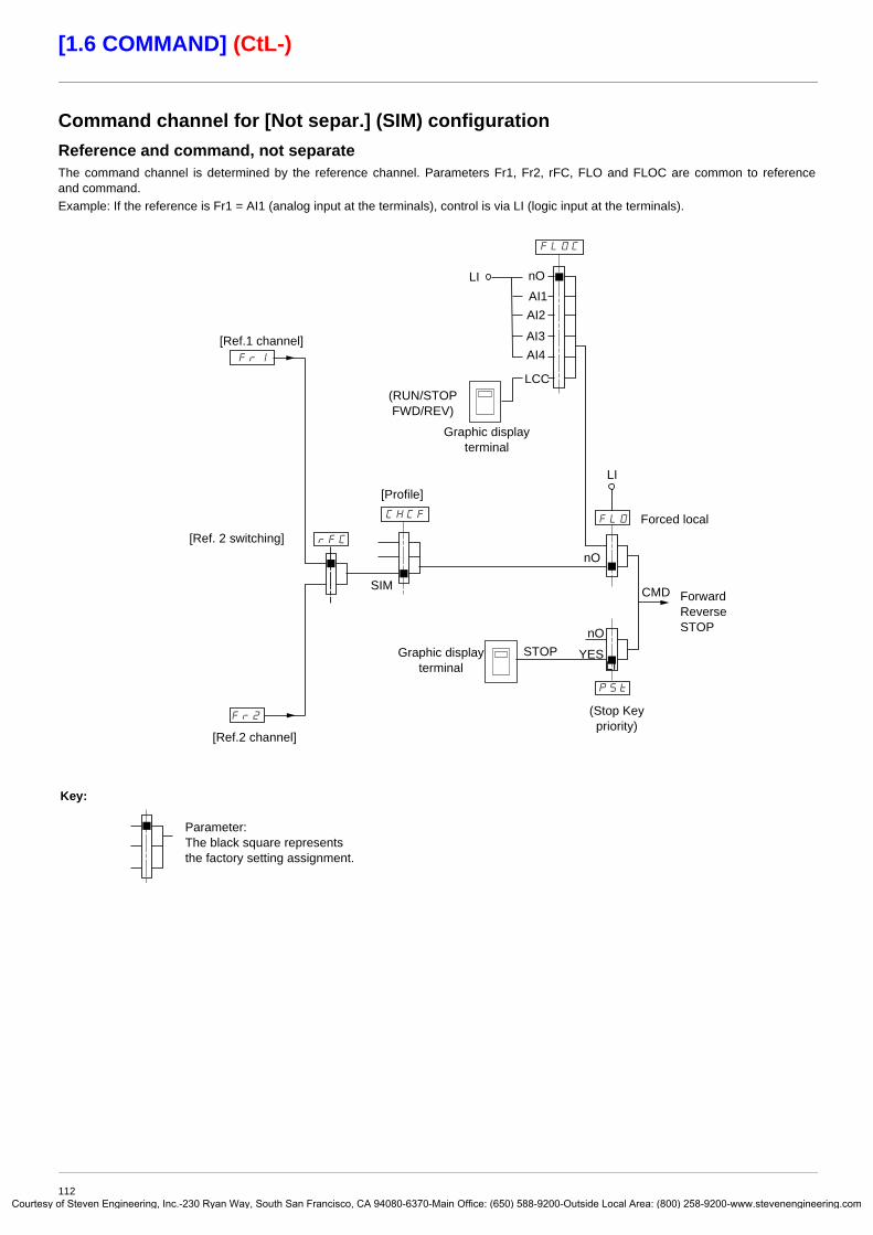
Courtes
[1.6 COMMAND] (CtL-)
Command channel for [Not separ.] (SIM) configurationReference and command, not separateThe command channel is determined by the reference channel. Parameters Fr1, Fr2, rFC, FLO and FLOC are common to reference and command. Example: If the reference is Fr1 = AI1 (analog input at the terminals), control is via LI (logic input at the terminals).
279/
/4/2
H2/
2H%
279
:;I
2H$
(Stop Key priority)
Forced local
Parameter:The black square representsthe factory setting assignment.
ForwardReverseSTOP
Graphic display terminal
Key:
Graphic display terminal
LIAI1
(RUN/STOP FWD/REV)
LCC
nO
AI2
AI3
LI
[Ref.1 channel]
[Ref.2 channel]
[Ref. 2 switching]
[Profile]
YES
SIM
STOP
CMD
LI
nO
AI4
nO
112y of Steven Engineering, Inc.-230 Ryan Way, South San Francisco, CA 94080-6370-Main Office: (650) 588-9200-Outside Local Area: (800) 258-9200-www.stevenengineering.com

Courtes
[1.6 COMMAND] (CtL-)
Command channel for [Separate] (SEP) configurationSeparate reference and commandParameters FLO and FLOC are common to reference and command. Example: If the reference is in forced local mode via AI1 (analog input at the terminals), command in forced local mode is via LI (logic input at the terminals).The command channels Cd1 and Cd2 are independent of the reference channels Fr1, Fr1b and Fr2.
CommandsCd1, Cd2:
• Terminals, graphic display terminal, integrated Modbus, integrated CANopen, communication card, Controller Inside card
279/
/4/2//;
/@%
279
:;I
/@$
(Stop Key priority)
Forced local
Parameter:The black rectangle represents the factory setting assignment, except for [Profile].
ForwardReverseSTOP
Graphic display terminal
Key:
Graphic display terminal
LIAI1
(RUN/STOP FWD/REV)
LCC
nO
AI2
AI3[Cmd channel 1]
[Cmd channel 2]
[Cmd switching][Profile]
YES
SEP
STOP
CMD
LI
nO
AI4
nO
113y of Steven Engineering, Inc.-230 Ryan Way, South San Francisco, CA 94080-6370-Main Office: (650) 588-9200-Outside Local Area: (800) 258-9200-www.stevenengineering.com

Courtes
[1.6 COMMAND] (CtL-)
Command channel for [I/O profile] (IO) configurationSeparate reference and command, as in [Separate] (SEP) configuration
The command channels Cd1 and Cd2 are independent of the reference channels Fr1, Fr1b and Fr2.
CommandsCd1, Cd2:
• Terminals, graphic display terminal, integrated Modbus, integrated CANopen, communication card, Controller Inside card
/4/2//;
/@%
279
:;I
/@$
(Stop Key priority)
Forced local
Parameter:The black rectangle represents the factory setting assignment, except for [Profile].
ForwardReverseSTOP
Key:
Graphic display terminal
nO
[Cmd channel 1]
[Cmd channel 2]
[Cmd switching][Profile]
YES
I/O
STOP
CMD
LI
nO
Note: Forced local is not active in [I/O profile].
114y of Steven Engineering, Inc.-230 Ryan Way, South San Francisco, CA 94080-6370-Main Office: (650) 588-9200-Outside Local Area: (800) 258-9200-www.stevenengineering.com

Courtes
[1.6 COMMAND] (CtL-)
Command channel for [I/O profile] (IO) configurationSelection of a command channel:A command or an action can be assigned:
• To a fixed channel by selecting an LI input or a Cxxx bit:- By selecting e.g., LI3, this action will always be triggered by LI3 regardless of which command channel is switched.- By selecting e.g., C214, this action will always be triggered by integrated CANopen with bit 14 regardless of which command
channel is switched.
• To a switchable channel by selecting a CDxx bit:- By selecting, e.g., CD11, this action will be triggered by
LI12 if the terminals channel is active C111 if the integrated Modbus channel is active C211 if the integrated CANopen channel is active C311 if the communication card channel is active C411 if the Controller Inside card channel is active
If the active channel is the graphic display terminal, the functions and commands assigned to CDxx switchable internal bits are inactive.
Note: • CD14 and CD15 can only be used for switching between 2 networks. They do not have equivalent logic inputs.
(1) If [2/3 wire control] (tCC) page 80 = [3 wire] (3C), LI2, C101, C201, C301, and C401 cannot be accessed.
Terminals Integrated Modbus Integrated CANopen Communication card
Controller Inside card
Internal bit, can be switched
CD00
LI2 (1) C101 (1) C201 (1) C301 (1) C401 (1) CD01
LI3 C102 C202 C302 C402 CD02
LI4 C103 C203 C303 C403 CD03
LI5 C104 C204 C304 C404 CD04
LI6 C105 C205 C305 C405 CD05
LI7 C106 C206 C306 C406 CD06
LI8 C107 C207 C307 C407 CD07
LI9 C108 C208 C308 C408 CD08
LI10 C109 C209 C309 C409 CD09
LI11 C110 C210 C310 C410 CD10
LI12 C111 C211 C311 C411 CD11
LI13 C112 C212 C312 C412 CD12
LI14 C113 C213 C313 C413 CD13
- C114 C214 C314 C414 CD14
- C115 C215 C315 C415 CD15
115y of Steven Engineering, Inc.-230 Ryan Way, South San Francisco, CA 94080-6370-Main Office: (650) 588-9200-Outside Local Area: (800) 258-9200-www.stevenengineering.com

Courtes
[1.6 COMMAND] (CtL-)
Assignment conditions for logic inputs and control bitsThe following elements are available for every command or function that can be assigned to a logic input or a control bit:
Note: In [I/O profile] (IO) configuration, LI1 cannot be accessed and if [2/3 wire control] (tCC) page 80 = [3 wire] (3C), LI2, C101, C201, C301, and C401 cannot be accessed either.
[LI1] (LI1)to
[LI6] (LI6)Drive with or without option
[LI7] (LI7)to
[LI10] (LI10)With VW3A3201 logic I/O card
[LI11] (LI11)to
[LI14] (LI14)With VW3A3202 extended I/O card
[C101] (C101)to
[C110] (C110)With integrated Modbus in [I/O profile] (IO) configuration
[C111] (C111)to
[C115] (C115)With integrated Modbus regardless of configuration
[C201] (C201)to
[C210] (C210)With integrated CANopen in [I/O profile] (IO) configuration
[C211] (C211)to
[C215] (C215)With integrated CANopen regardless of configuration
[C301] (C301)to
[C310] (C310)With a communication card in [I/O profile] (IO) configuration
[C311] (C311)to
[C315] (C315)With a communication card regardless of configuration
[C401] (C401)to
[C410] (C410)With Controller Inside card in [I/O profile] (IO) configuration
[C411] (C411)to
[C415] (C415)With Controller Inside card regardless of configuration
[CD00] (Cd00)to
[CD10] (Cd10)In [I/O profile] (IO) configuration
[CD11] (Cd11)to
[CD15] (Cd15)Regardless of configuration
WARNINGUNINTENDED EQUIPMENT OPERATIONInactive communication channels are not monitored (no lock following malfunction in the event of a communication bus failure). Make sure that the commands and functions assigned to bits C101 to C415 will not pose a risk in the event of the failure of the associated communication bus.
Failure to follow these instructions can result in death or serious injury.
116y of Steven Engineering, Inc.-230 Ryan Way, South San Francisco, CA 94080-6370-Main Office: (650) 588-9200-Outside Local Area: (800) 258-9200-www.stevenengineering.com

Courtes
[1.6 COMMAND] (CtL-)
Code Name/Description Adjustment range Factory setting
Fr1 M [Ref.1 channel] [AI1] (AI1)
AI1
AI2
AI3
AI4
LCC
Mdb
CAn
nEt
APP
PI
PG
v [AI1] (AI1): Analog inputv [AI2] (AI2): Analog inputv [AI3] (AI3): Analog input, if VW3A3202 extension card has been insertedv [AI4] (AI4): Analog input, if VW3A3202 extension card has been insertedv [HMI] (LCC): Graphic display terminalv [Modbus] (Mdb): Integrated Modbusv [CANopen] (CAn): Integrated CANopenv [Com. card] (nEt): Communication card (if inserted)v [Prog. card] (APP): Controller Inside card (if inserted)v [RP] (PI): Frequency input, if VW3A3202 extension card has been insertedv [Encoder] (PG): Encoder input, if encoder card has been inserted
rIn M [RV Inhibition] [No] (nO)
nO
YES
v [No] (nO) v [Yes] (YES)
Inhibition of movement in reverse direction, does not apply to direction requests sent by logic inputs.- Reverse direction requests sent by logic inputs are taken into account.- Reverse direction requests sent by the graphic display terminal are not taken into account.- Reverse direction requests sent by the line are not taken into account.- Any reverse speed reference originating from the PID, summing input, etc., is interpreted as a zero
reference (0 Hz).
PSt M [Stop Key priority] [Yes] (YES)
nO
YES
v [No] (nO) v [Yes] (YES): Gives priority to the STOP key on the graphic display terminal when the graphic display
terminal is not enabled as the command channel.Press and hold down ENT for 2 seconds in order for any change in the assignment of [Stop Key priority] (PSt) to be taken into account.This will be a freewheel stop. If the active command channel is the graphic display terminal, the stop will be performed according to the [Type of stop] (Stt) page 133 irrespective of the configuration of [Stop Key priority] (PSt).
CHCF M [Profile] [Not separ.] (SIM)
SE8
SIM
SEP
IO
v [8 serie] (SE8): ATV38 interchangeability (see Migration Manual). The [8 serie] (SE8) configuration is used to load, via PowerSuite, for example, an ATV38 drive configuration in an ATV61 that has already been set to this configuration. This assignment cannot be accessed if a Controller Inside card has been inserted.
Note: Modifications to the configuration of the ATV61 must only be made using PowerSuite when it is in this configuration, otherwise operation cannot be guaranteed.
v [Not separ.] (SIM): Reference and command, not separatev [Separate] (SEP): Separate reference and command This assignment cannot be accessed in
[I/O profile] (IO).v [I/O profile] (IO): I/O profile
When [8 serie] (SE8) is selected and [I/O profile] (IO) is deselected, the drive automatically returns to the factory setting (this is mandatory). This factory setting only affects the [1 DRIVE MENU] menu. It does not affect either [1.9 COMMUNICATION] or [1.14 PROGRAMMABLE CARD].
- With the graphic display terminal, a screen appears to perform this operation. Follow the instructions on the screen.
- With the integrated display terminal, press ENT and hold it down (for 2 s). This will save the selection and return to the factory setting.
117y of Steven Engineering, Inc.-230 Ryan Way, South San Francisco, CA 94080-6370-Main Office: (650) 588-9200-Outside Local Area: (800) 258-9200-www.stevenengineering.com

Courtes
[1.6 COMMAND] (CtL-)
Code Name/Description Adjustment range Factory setting
CCS M [Cmd switching] [ch1 active] (Cd1)
Cd1
Cd2
LI1
-
-
-
The parameter can be accessed if [Profile] (CHCF) = [Separate] (SEP) or [I/O profile] (IO)v [ch1 active] (Cd1): [Cmd channel 1] (Cd1) active (no switching)v [ch2 active] (Cd2): [Cmd channel 2] (Cd2) active (no switching)
v [LI1] (LI1) : :
v [...] (...): See the assignment conditions on page 116 (not CDOO to CD14).
If the assigned input or bit is at 0, channel [Cmd channel 1] (Cd1) is active.If the assigned input or bit is at 1, channel [Cmd channel 2] (Cd2) is active.
Cd1 M [Cmd channel 1] [Terminals] (tEr)
tEr
LCC
Mdb
CAn
nEt
APP
v [Terminals] (tEr): Terminalsv [HMI] (LCC): Graphic display terminalv [Modbus] (Mdb): Integrated Modbusv [CANopen] (CAn): Integrated CANopenv [Com. card] (nEt): Communication card (if inserted)v [Prog. card] (APP): Controller Inside card (if inserted)
The parameter is available if [Profile] (CHCF) = [Separate] (SEP) or [I/O profile] (IO).
Cd2 M [Cmd channel 2] [Modbus] (Mdb)
tEr
LCC
Mdb
CAn
nEt
APP
v [Terminals] (tEr): Terminalsv [HMI] (LCC): Graphic display terminalv [Modbus] (Mdb): Integrated Modbusv [CANopen] (CAn): Integrated CANopenv [Com. card] (nEt): Communication card (if inserted)v [Prog. card] (APP): Controller Inside card (if inserted)
The parameter is available if [Profile] (CHCF) = [Separate] (SEP) or [I/O profile] (IO).
rFC M [Ref. 2 switching] [ch1 active] (Fr1)
Fr1
Fr2
LI1
-
-
-
v [ch1 active] (Fr1): No switching, [Ref.1 channel] (Fr1) activev [ch2 active] (Fr2): No switching, [Ref.2 channel] (Fr2) activev [LI1] (LI1)
: :
v [...] (...): See the assignment conditions on page 116 (not CDOO to CD14).
If the assigned input or bit is at 0, channel [Ref.1 channel] (Fr1) is active.If the assigned bit or input is at 1, channel [Ref.2 channel] (Fr2) is active.
Fr2 M [Ref.2 channel] [No] (nO)
nO
AI1
AI2
AI3
AI4
UPdt
LCC
Mdb
CAn
nEt
APP
PI
PG
v [No] (nO): Not assigned If [Profile] (CHCF) = [Not separ.] (SIM), command is at the terminals with a zero reference. If [Profile] (CHCF) = [Separate] (SEP) or [I/O profile] (IO), the reference is zero.
v [AI1] (AI1): Analog inputv [AI2] (AI2): Analog inputv [AI3] (AI3): Analog input, if VW3A3202 extension card has been insertedv [AI4] (AI4): Analog input, if VW3A3202 extension card has been insertedv [+/- Speed] (UPdt): +/-Speed commandv [HMI] (LCC): Graphic display terminalv [Modbus] (Mdb): Integrated Modbusv [CANopen] (CAn): Integrated CANopenv [Com. card] (nEt): Communication card (if inserted)v [Prog. card] (APP): Controller Inside card (if inserted)v [RP] (PI): Frequency input, if VW3A3202 extension card has been insertedv [Encoder] (PG): Encoder input, if encoder card has been inserted
118y of Steven Engineering, Inc.-230 Ryan Way, South San Francisco, CA 94080-6370-Main Office: (650) 588-9200-Outside Local Area: (800) 258-9200-www.stevenengineering.com

Courtes
[1.6 COMMAND] (CtL-)
Code Name/Description Adjustment range Factory setting
COP M [Copy channel 1 <> 2] [No] (nO)
nO
SP
Cd
ALL
Can be used to copy the current reference and/or the command by means of switching, in order to avoid speed surges, for example.If [Profile] (CHCF) page 117 = [Not separ.] (SIM) or [Separate] (SEP), copying will only be possible from channel 1 to channel 2.If [Profile] (CHCF) = [I/O profile] (IO), copying will be possible in both directions.
v [No] (nO): No copyv [Reference] (SP): Copy referencev [Command] (Cd): Copy commandv [Cmd + ref.] (ALL): Copy command and reference
- A reference or a command cannot be copied to a channel on the terminals.- The reference copied is FrH (before ramp) unless the destination channel reference is set via +/- speed.
In this case, the reference copied is rFr (after ramp).
WARNINGUNINTENDED EQUIPMENT OPERATIONCopying the command and/or reference can change the direction of rotation.Check that this is safe.Failure to follow these instructions can result in death or serious injury.
119y of Steven Engineering, Inc.-230 Ryan Way, South San Francisco, CA 94080-6370-Main Office: (650) 588-9200-Outside Local Area: (800) 258-9200-www.stevenengineering.com

Courtes
[1.6 COMMAND] (CtL-)
As the graphic display terminal may be selected as the command and/or reference channel, its action modes can be configured.The parameters on this page can only be accessed on the graphic display terminal, and not on the integrated display terminal.
Notes:• The display terminal command/reference is only active if the command and/or reference channels from the terminal are active,
with the exception of [T/K] (command and reference via the display terminal), which takes priority over these channels. Press [T/K] again or turn off the drive to revert control to the selected channel.
•Note: The channel selected by pressing [T/K] remains active after a return to factory settings, until [T/K] is pressed again or the drive is turned off.
• Command and reference via the display terminal are impossible if the latter is connected to more than one drive.• The JOG, preset speed and +/- speed functions can only be accessed if [Profile] (CHCF) = [Not separ.] (SIM).• The preset PID reference functions can only be accessed if [Profile] (CHCF) = [Not separ.] (SIM) or [Separate] (SEP).• The [T/K] function (command and reference via the display terminal) can be accessed regardless of the [Profile] (CHCF).
Name/Description Adjustment range Factory setting
M [F1 key assignment] [No]
v [No]: Not assignedv [Jog]: JOG operationv [Preset spd2]: Press the key to run the drive at the 2nd preset speed [Preset speed 2] (SP2) page 140. Press STOP to
stop the drive.v [Preset spd3]: Press the key to run the drive at the 3rd preset speed [Preset speed 3] (SP3) page 140. Press STOP to stop
the drive.v [PID ref. 2]: Sets a PID reference equal to the 2nd preset PID reference [Preset ref. PID 2] (rP2) page 156 without sending
a run command. Only operates if [Ref.1 channel] (Fr1) = [HMI] (LCC). Does not operate with the [T/K] function.v [PID ref. 3]: Sets a PID reference equal to the 3rd preset PID reference [Preset ref. PID 3] (rP3) page 156 without sending
a run command. Only operates if [Ref.1 channel] (Fr1) = [HMI] (LCC). Does not operate with the [T/K] function.v [+Speed]: Faster, only operates if [Ref.2 channel] (Fr2) = [HMI] (LCC). Press the key to run the drive and increase the speed.
Press STOP to stop the drive.v [-Speed]: Slower, only operates if [Ref.2 channel] (Fr2) = [HMI] (LCC) and if a different key is assigned to [+Speed].
Press the key to run the drive and decrease the speed. Press STOP to stop the drive.v [T/K]: Command and reference via the display terminal: Takes priority over [Cmd switching] (CCS) and over
[Ref. 2 switching] (rFC).
M [F2 key assignment] [No]
Identical to [F1 key assignment].
M [F3 key assignment] [No]
Identical to [F1 key assignment].
M [F4 key assignment] [T/K]
Identical to [F1 key assignment].
M [HMI cmd.] [Bumpless]
When the [T/K] function is assigned to a key and that function is active, this parameter defines the behavior at the moment when control returns to the graphic display terminal.
v [Stop]: Stops the drive (although the controlled direction of operation and reference of the previous channel are copied (to be taken into account on the next RUN command)).
v [Bumpless]: Does not stop the drive (the controlled direction of operation and the reference of the previous channel are copied).
120y of Steven Engineering, Inc.-230 Ryan Way, South San Francisco, CA 94080-6370-Main Office: (650) 588-9200-Outside Local Area: (800) 258-9200-www.stevenengineering.com

Courtes
[1.7 APPLICATION FUNCT.] (FUn-)
With graphic display terminal:
With integrated display terminal: Summary of functions:
Code Name PagerEF- [REFERENCE SWITCH.] 127
OAI- [REF. OPERATIONS] 128
rPt- [RAMP] 129
Stt- [STOP CONFIGURATION] 133
AdC- [AUTO DC INJECTION] 135
JOG- [JOG] 137
PSS- [PRESET SPEEDS] 139
UPd- [+/-Speed] 142
SrE- [+/-SPEED AROUND REF.] 144
SPM- [MEMO REFERENCE] 145
FLI- [FLUXING BY LI] 146
PId- [PID REGULATOR] 151
Pr1- [PID PRESET REFERENCES] 156
SrM- [SLEEPING / WAKE UP] 158
tOL- [TORQUE LIMITATION] 164
CLI- [2nd CURRENT LIMIT.] 166
LLC- [LINE CONTACTOR COMMAND] 168
OCC- [OUTPUT CONTACTOR CMD] 170
dAM- [DAMPER MANAGEMENT] 172
MLP- [PARAM. SET SWITCHING] 174
MMC- [MULTIMOTORS/CONFIG.] 179
tnL- [AUTO TUNING BY LI] 179
nFS- [NO FLOW DETECTION] 181
FLL- [FLOW LIMITATION] 183
dCO- [DC BUS SUPPLY] 184
RDY Term +0.00 Hz REMMAIN MENU
1 DRIVE MENU2 ACCESS LEVEL3 OPEN / SAVE AS4 PASSWORD5 LANGUAGE
Code T/K6 MONITORING CONFIG.7 DISPLAY CONFIG.
ENT
RDY Term +0.00 Hz REM1 DRIVE MENU
1.1 SIMPLY START1.2 MONITORING1.3 SETTINGS1.4 MOTOR CONTROL1.5 INPUTS / OUTPUTS CFG
Code << >> T/K1.6 COMMAND1.7 APPLICATION FUNCT.1.8 FAULT MANAGEMENT1.9 COMMUNICATION1.10 DIAGNOSTICS1.11 IDENTIFICATION1.12 FACTORY SETTINGS1.13 USER MENU1.14 PROGRAMMABLE CARD
ENTRUN Term +0.00 Hz REM
1.7 APPLICATION FUNCT.REFERENCE SWITCH.REF. OPERATIONSRAMPSTOP CONFIGURATIONAUTO DC INJECTION
Code << >> T/K
XXX
CtL-
FUn-
SIM-
ESC
ESC
ESC
ESC
ENT
ENT
ESC
LAC-
FLt-
ESC
Displays the drive state
APPLICATION FUNCT.
Power-up
121y of Steven Engineering, Inc.-230 Ryan Way, South San Francisco, CA 94080-6370-Main Office: (650) 588-9200-Outside Local Area: (800) 258-9200-www.stevenengineering.com

Courtes
[1.7 APPLICATION FUNCT.] (FUn-)
The parameters in the [1.7 APPLICATION FUNCT.] (FUn-) menu can only be modified when the drive is stopped and there is no run command, except for parameters with a symbol in the code column, which can be modified with the drive running or stopped.
Note: Compatibility of functionsThe choice of application functions may be limited by the number of I/O and by the fact that some functions are incompatible with
one another. Functions that are not listed in the table below are fully compatible.If there is an incompatibility between functions, the first function configured will prevent the others being configured.
Each of the functions on the following pages can be assigned to one of the inputs or outputs. A single input can activate several functions at the same time (reverse and 2nd ramp, for example). The user must therefore ensure that these functions can be used at the same time. It is only possible to assign one input to several functions at [Advanced] (AdU) and[Expert] (EPr) level.
Before assigning a command, reference or function to an input or output, the user must make sure that this input or output has not already been assigned and that another input or output has not been assigned to an incompatible or undesirable function.The drive factory setting or macro configurations automatically configure functions, which may prevent other functions being assigned.It may be necessary to unconfigure one or more functions in order to be able to enable another. Check the compatibility table below.
122y of Steven Engineering, Inc.-230 Ryan Way, South San Francisco, CA 94080-6370-Main Office: (650) 588-9200-Outside Local Area: (800) 258-9200-www.stevenengineering.com

Courtes
[1.7 APPLICATION FUNCT.] (FUn-)
Compatibility table
(1)Priority is given to the first of these two stop modes to be activated.(2)Excluding special application with reference channel Fr2 (see diagrams on pages 110 and 111).(3)Only the multiplier reference is incompatible with the PID regulator.
Stop functions have priority over run commands.Speed references via logic command have priority over analog references.
Note: This compatibility table does not affect commands that can be assigned to the keys of the graphic display terminal (see page 120).
Ref
. ope
ratio
ns (p
age
128)
+/- s
peed
(2) (
page
142
)
Pre
set s
peed
s (p
age
139)
PID
regu
lato
r (pa
ge 1
51)
JOG
ope
ratio
n (p
age
137)
DC
inje
ctio
n st
op (p
age
133)
Fast
sto
p (p
age
133)
Free
whe
el s
top
(pag
e 13
3)
+/- s
peed
aro
und
a re
fere
nce
(pag
e 14
4)
Syn
chro
nous
mot
or (p
age
67)
Ref. operations (page 128) A p(3) A+/- speed (2) (page 142) p
Preset speeds (page 139) X APID regulator (page 151) p(3) p p
JOG operation (page 137) X p X p p
DC injection stop (page 133) p(1) A p
Fast stop (page 133) p(1) AFreewheel stop (page 133) X X+/- speed around a reference (page 144) p p
Synchronous motor (page 67) p
Incompatible functions Compatible functions N/A
The function marked with the arrow takes priority over the other.
Priority functions (functions, which cannot be active at the same time):
123y of Steven Engineering, Inc.-230 Ryan Way, South San Francisco, CA 94080-6370-Main Office: (650) 588-9200-Outside Local Area: (800) 258-9200-www.stevenengineering.com

Courtes
[1.7 APPLICATION FUNCT.] (FUn-)
Incompatible functionsThe following functions will be inaccessible or deactivated in the cases described below:
Automatic restartThis is only possible for control type [2/3 wire control] (tCC) = [2 wire] (2C) and [2 wire type] (tCt) = [Level] (LEL) or [Fwd priority] (PFO). See page 80.
Catch on the flyThis is only possible for control type [2/3 wire control] (tCC) = [2 wire] (2C) and [2 wire type] (tCt) = [Level] (LEL) or [Fwd priority] (PFO). See page 80. This function is locked if automatic injection on stop [Auto DC injection] (AdC) = [Continuous] (Ct). See page 135.
The SUP- monitoring menu (page 38) can be used to display the functions assigned to each input in order to check their compatibility.
When a function is assigned, a appears on the graphic display terminal, as illustrated in the example below:
If you attempt to assign a function that is incompatible with another function that has already been assigned, an alarm message will appear:With the graphic display terminal
With the integrated display terminal: COMP flashes until ENT or ESC is pressed.
When you assign a logic input, an analog input, a reference channel or a bit to a function, pressing the HELP button will display the functions that may already have been activated by this input, bit or channel.
RDY Term +0.00 Hz REM1.7 APPLICATION FUNCT.
REFERENCE SWITCH.REF. OPERATIONSRAMPSTOP CONFIGURATIONAUTO DC INJECTION
Code << >> T/KJOG
RDY Term +0.00 Hz REMINCOMPATIBILITY
The function can't be assignedbecause an incompatiblefunction is already selected. Seeprogramming book.ENT or ESC to continue
124y of Steven Engineering, Inc.-230 Ryan Way, South San Francisco, CA 94080-6370-Main Office: (650) 588-9200-Outside Local Area: (800) 258-9200-www.stevenengineering.com

Courtes
[1.7 APPLICATION FUNCT.] (FUn-)
When a logic input, an analog input, a reference channel or a bit that has already been assigned is assigned to another function, the following screens appear:With the graphic display terminal
If the access level permits this new assignment, pressing ENT confirms the assignment.If the access level does not permit this new assignment, pressing ENT results in the following display.
With the integrated display terminal:
The code for the first function, which is already assigned, is displayed flashing. If the access level permits this new assignment, pressing ENT confirms the assignment.If the access level does not permit this new assignment, pressing ENT has no effect, and the message continues to flash. It is only possible to exit by pressing ESC.
RUN +50.00 Hz 1250A +50.00 HzWARNING - ASSIGNED TO
Reference switch. 2
ENT->Continue ESC->Cancel
RUN +50.00 Hz 1250A +50.00 HzASSIGNMENT FORBIDDEN
Un-assign the presentfunctions, or selectAdvanced access level
125y of Steven Engineering, Inc.-230 Ryan Way, South San Francisco, CA 94080-6370-Main Office: (650) 588-9200-Outside Local Area: (800) 258-9200-www.stevenengineering.com
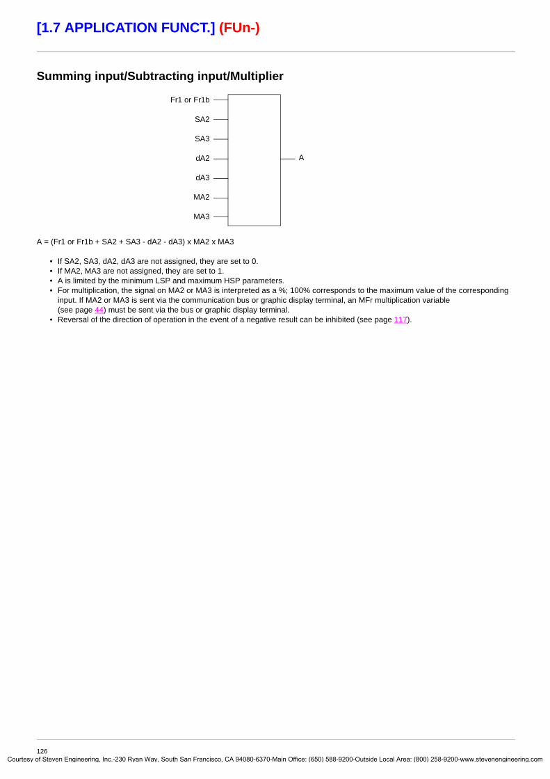
Courtes
[1.7 APPLICATION FUNCT.] (FUn-)
Summing input/Subtracting input/Multiplier
A = (Fr1 or Fr1b + SA2 + SA3 - dA2 - dA3) x MA2 x MA3
• If SA2, SA3, dA2, dA3 are not assigned, they are set to 0.• If MA2, MA3 are not assigned, they are set to 1.• A is limited by the minimum LSP and maximum HSP parameters.• For multiplication, the signal on MA2 or MA3 is interpreted as a %; 100% corresponds to the maximum value of the corresponding
input. If MA2 or MA3 is sent via the communication bus or graphic display terminal, an MFr multiplication variable (see page 44) must be sent via the bus or graphic display terminal.
• Reversal of the direction of operation in the event of a negative result can be inhibited (see page 117).
Fr1 or Fr1b
SA2
SA3
dA2
dA3
MA2
MA3
A
126y of Steven Engineering, Inc.-230 Ryan Way, South San Francisco, CA 94080-6370-Main Office: (650) 588-9200-Outside Local Area: (800) 258-9200-www.stevenengineering.com

Courtes
[1.7 APPLICATION FUNCT.] (FUn-)
Code Name/Description Adjustment range Factory setting
rEF- b [REFERENCE SWITCH.]rCb M [Ref 1B switching]
See the diagrams on pages 110 and 111.
[LI3] (LI3)
Fr1
Fr1b
LI1
-
-
-
v [ch1 active] (Fr1): No switching, [Ref.1 channel] (Fr1) activev [ch1B active] (Fr1b): No switching, [Ref.1B channel] (Fr1b) active
v [LI1] (LI1) : :
v [...] (...): See the assignment conditions on page 116 (not CDOO to CD14).
• If the assigned input or bit is at 0, [Ref.1 channel] (Fr1) is active (see page 117).• If the assigned input or bit is at 1, [Ref.1B channel] (Fr1b) is active.
[Ref 1B switching] (rCb) is forced to [ch1 active] (Fr1) if [Profile] (CHCF) = [Not separ.] (SIM) with [Ref.1 channel] (Fr1) assigned via the terminals (analog inputs, encoder, pulse input); see page 117.
Fr1b M [Ref.1B channel] [AI2] (AI2)
nO
AI1
AI2
AI3
AI4
LCC
Mdb
CAn
nEt
APP
PI
PG
v [No] (nO): Not assigned v [AI1] (AI1): Analog inputv [AI2] (AI2): Analog inputv [AI3] (AI3): Analog input, if VW3A3202 extension card has been insertedv [AI4] (AI4): Analog input, if VW3A3202 extension card has been insertedv [HMI] (LCC): Graphic display terminalv [Modbus] (Mdb): Integrated Modbusv [CANopen] (CAn): Integrated CANopenv [Com. card] (nEt): Communication card (if inserted)v [Prog. card] (APP): Controller Inside card (if inserted)v [RP] (PI): Frequency input, if VW3A3202 extension card has been insertedv [Encoder] (PG): Encoder input, if encoder card has been inserted
Note: In the following instances, only assignments via the terminals are possible:
- [Profile] (CHCF) = [Not separ.] (SIM) with [Ref.1 channel] (Fr1) assigned via the terminals (analog inputs, encoder, pulse input); see page 117.
- PID configured with PID references via the terminals
127y of Steven Engineering, Inc.-230 Ryan Way, South San Francisco, CA 94080-6370-Main Office: (650) 588-9200-Outside Local Area: (800) 258-9200-www.stevenengineering.com

Courtes
[1.7 APPLICATION FUNCT.] (FUn-)
Code Name/Description Adjustment range Factory setting
OAI- b [REF. OPERATIONS]Reference = (Fr1 or Fr1b + SA2 + SA3 - dA2 - dA3) x MA2 x MA3. See the diagrams on pages 110 and 111.
Note: This function cannot be used with certain other functions. Follow the instructions on page 122.
SA2 M [Summing ref. 2] [No] (nO)
nO
AI1
AI2
AI3
AI4
LCC
Mdb
CAn
nEt
APP
PI
PG
AIU1
Selection of a reference to be added to [Ref.1 channel] (Fr1) or [Ref.1B channel] (Fr1b).v [No] (nO): No source assignedv [AI1] (AI1): Analog inputv [AI2] (AI2): Analog inputv [AI3] (AI3): Analog input, if VW3A3202 extension card has been insertedv [AI4] (AI4): Analog input, if VW3A3202 extension card has been insertedv [HMI] (LCC): Graphic display terminalv [Modbus] (Mdb): Integrated Modbusv [CANopen] (CAn): Integrated CANopenv [Com. card] (nEt): Communication card (if inserted)v [Prog. card] (APP): Controller Inside card (if inserted)v [RP] (PI): Frequency input, if VW3A3202 extension card has been insertedv [Encoder] (PG): Encoder input, if encoder card has been insertedv [Network AI] (AIU1): Virtual input via communication bus, to be configured via [AI net. channel] (AIC1)
page 89
SA3 M [Summing ref. 3] [No] (nO)
Selection of a reference to be added to [Ref.1 channel] (Fr1) or [Ref.1B channel] (Fr1b).• Possible assignments are identical to [Summing ref. 2] (SA2) above.
dA2 M [Subtract. ref. 2] [No] (nO)
Selection of a reference to be subtracted from [Ref.1 channel] (Fr1) or [Ref.1B channel] (Fr1b).• Possible assignments are identical to [Summing ref. 2] (SA2) above.
dA3 M [Subtract. ref. 3] [No] (nO)
Selection of a reference to be subtracted from [Ref.1 channel] (Fr1) or [Ref.1B channel] (Fr1b).• Possible assignments are identical to [Summing ref. 2] (SA2) above.
MA2 M [Multiplier ref. 2] [No] (nO)
Selection of a multiplier reference [Ref.1 channel] (Fr1) or [Ref.1B channel] (Fr1b).• Possible assignments are identical to [Summing ref. 2] (SA2) above.
MA3 M [Multiplier ref. 3] [No] (nO)
Selection of a multiplier reference [Ref.1 channel] (Fr1) or [Ref.1B channel] (Fr1b).• Possible assignments are identical to [Summing ref. 2] (SA2) above.
WARNINGUNINTENDED EQUIPMENT OPERATIONIf the equipment switches to forced local mode (see page 214), the virtual input remains frozen at the last value transmitted.Do not use the virtual input and forced local mode in the same configuration.Failure to follow this instruction can result in death or serious injury.
128y of Steven Engineering, Inc.-230 Ryan Way, South San Francisco, CA 94080-6370-Main Office: (650) 588-9200-Outside Local Area: (800) 258-9200-www.stevenengineering.com
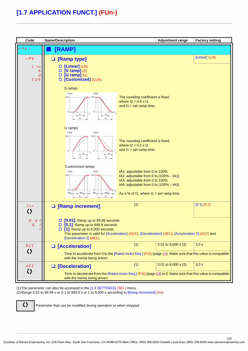
Courtes
[1.7 APPLICATION FUNCT.] (FUn-)
(1)The parameter can also be accessed in the [1.3 SETTINGS] (SEt-) menu.(2)Range 0.01 to 99.99 s or 0.1 to 999.9 s or 1 to 9,000 s according to [Ramp increment] (Inr).
Code Name/Description Adjustment range Factory setting
rPt- b [RAMP]
rPt M [Ramp type] [Linear] (LIn)
LIn
S
U
CUS
v [Linear] (LIn)v [S ramp] (S)v [U ramp] (U)v [Customized] (CUS)
S ramps
The rounding coefficient is fixed, where t2 = 0.6 x t1 and t1 = set ramp time.
The rounding coefficient is fixed, where t2 = 0.5 x t1 and t1 = set ramp time.
tA1: adjustable from 0 to 100% tA2: adjustable from 0 to (100% – tA1) tA3: adjustable from 0 to 100% tA4: adjustable from 0 to (100% – tA3)
As a % of t1, where t1 = set ramp time
Inr M [Ramp increment] (1) [0.1] (0.1)
0.01
0.1
1
v [0.01]: Ramp up to 99.99 secondsv [0.1]: Ramp up to 999.9 secondsv [1]: Ramp up to 9,000 seconds
This parameter is valid for [Acceleration] (ACC), [Deceleration] (dEC), [Acceleration 2] (AC2) and [Deceleration 2] (dE2).
ACC M [Acceleration] (1) 0.01 to 9,000 s (2) 3.0 s
Time to accelerate from 0 to the [Rated motor freq.] (FrS) (page 64). Make sure that this value is compatible with the inertia being driven.
dEC M [Deceleration] (1) 0.01 to 9,000 s (2) 3.0 s
Time to decelerate from the [Rated motor freq.] (FrS) (page 64) to 0. Make sure that this value is compatible with the inertia being driven.
Parameter that can be modified during operation or when stopped.
FrS
t0
t2
t1
f (Hz)
FrS
t0
t2
t1
f (Hz)
FrS
t0tA1 tA2 tA3 tA4
t1
f (Hz)
FrS
t0
t1
f (Hz)
FrS
t0
t2
t1
f (Hz)
FrS
t0
t2
t1
f (Hz)
U ramps
Customized ramps
129y of Steven Engineering, Inc.-230 Ryan Way, South San Francisco, CA 94080-6370-Main Office: (650) 588-9200-Outside Local Area: (800) 258-9200-www.stevenengineering.com

Courtes
[1.7 APPLICATION FUNCT.] (FUn-)
(1)The parameter can also be accessed in the [1.3 SETTINGS] (SEt-) menu.
Code Name/Description Adjustment range Factory setting
b [RAMP] (continued)
tA1 M [Begin Acc round] (1) 0 to 100% 10%
- Rounding of start of acceleration ramp as a % of the [Acceleration] (ACC) or [Acceleration 2] (AC2) ramp time.
- Can be set between 0 and 100%- The parameter can be accessed if the [Ramp type] (rPt) is [Customized] (CUS).
tA2 M [End Acc round] (1) 10%
- Rounding of end of acceleration ramp as a % of the [Acceleration] (ACC) or [Acceleration 2] (AC2) ramp time.
- Can be set between 0 and (100% – [Begin Acc round] (tA1))- The parameter can be accessed if the [Ramp type] (rPt) is [Customized] (CUS).
tA3 M [Begin Dec round] (1) 0 to 100% 10%
- Rounding of start of deceleration ramp as a % of the [Deceleration] (dEC) or [Deceleration 2] (dE2) ramp time.
- Can be set between 0 and 100%- The parameter can be accessed if the [Ramp type] (rPt) is [Customized] (CUS).
tA4 M [End Dec round] (1) 10%
- Rounding of end of deceleration ramp as a % of the [Deceleration] (dEC) or [Deceleration 2] (dE2) ramp time.
- Can be set between 0 and (100% – [Begin Dec round] (tA3))- The parameter can be accessed if the [Ramp type] (rPt) is [Customized] (CUS).
Parameter that can be modified during operation or when stopped.
130y of Steven Engineering, Inc.-230 Ryan Way, South San Francisco, CA 94080-6370-Main Office: (650) 588-9200-Outside Local Area: (800) 258-9200-www.stevenengineering.com

Courtes
[1.7 APPLICATION FUNCT.] (FUn-)
(1)The parameter can also be accessed in the [1.3 SETTINGS] (SEt-) menu.(2)Range 0.01 to 99.99 s or 0.1 to 999.9 s or 1 to 9,000 s according to [Ramp increment] (Inr) page 129.
Code Name/Description Adjustment range Factory setting
b [RAMP] (continued)
Frt M [Ramp 2 threshold] 0 to 500 or 1,000 Hz according to rating
0 Hz
Ramp switching thresholdThe 2nd ramp is switched if the value of Frt is not 0 (0 deactivates the function) and the output frequency is greater than Frt.Threshold ramp switching can be combined with [Ramp switch ass.] (rPS) switching as follows:
rPS M [Ramp switch ass.] [No] (nO)
nO
LI1
-
-
-
v [No] (nO): Not assigned.
v [LI1] (LI1) : :
v [...] (...): See the assignment conditions on page 116.
- ACC and dEC are enabled when the assigned input or bit is at 0.- AC2 and dE2 are enabled when the assigned input or bit is at 1.
AC2 M [Acceleration 2] (1) 0.01 to 9,000 s (2) 5.0 s
Time to accelerate from 0 to the [Rated motor freq.] (FrS). Make sure that this value is compatible with the inertia being driven. The parameter can be accessed if [Ramp 2 threshold] (Frt) > 0 or if [Ramp switch ass.] (rPS) is assigned.
dE2 M [Deceleration 2] (1) 0.01 to 9,000 s (2) 5.0 s
Time to decelerate from [Rated motor freq.] (FrS) to 0. Make sure that this value is compatible with the inertia being driven. The parameter can be accessed if [Ramp 2 threshold] (Frt) > 0 or if [Ramp switch ass.] (rPS) is assigned.
Parameter that can be modified during operation or when stopped.
LI or bit Frequency Ramp
0 <Frt ACC, dEC
0 >Frt AC2, dE2
1 <Frt AC2, dE2
1 >Frt AC2, dE2
131y of Steven Engineering, Inc.-230 Ryan Way, South San Francisco, CA 94080-6370-Main Office: (650) 588-9200-Outside Local Area: (800) 258-9200-www.stevenengineering.com

Courtes
[1.7 APPLICATION FUNCT.] (FUn-)
Code Name/Description Adjustment range Factory setting
brA M [Dec ramp adapt.] [Yes] (YES)
nO
YES
dYnA
dYnb
dYnC
Activating this function automatically adapts the deceleration ramp, if this has been set at too low a value for the inertia of the load, which can cause an overvoltage fault.
v [No] (nO): Function inactivev [Yes] (YES): Function active, for applications that do not require strong deceleration.
The following selections appear depending on the rating of the drive and in accordance with [Motor control type] (Ctt) page 67. They enable stronger deceleration to be obtained than with [Yes] (YES). Use comparative testing to determine your selection.
v [High torq. A] (dYnA)v [High torq. B] (dYnb)v [High torq. C] (dYnC)
[Dec ramp adapt.] (brA) is forced to [No] (nO) if [Braking balance] (bbA) page 78 = [Yes] (YES).The function is incompatible with applications requiring:
- Positioning on a ramp- The use of a braking resistor (the resistor would not operate correctly).
CAUTIONDo not use [High torq. A] (dYnA), [High torq. B] (dYnB) or [High torq. C] (dYnC) configurations if the motor is a permanent magnet synchronous motor, as it will be demagnetized.Failure to follow this instruction can result in equipment damage.
132y of Steven Engineering, Inc.-230 Ryan Way, South San Francisco, CA 94080-6370-Main Office: (650) 588-9200-Outside Local Area: (800) 258-9200-www.stevenengineering.com

Courtes
[1.7 APPLICATION FUNCT.] (FUn-)
(1)The parameter can also be accessed in the [1.3 SETTINGS] (SEt-) menu.
Code Name/Description Adjustment range Factory setting
Stt- b [STOP CONFIGURATION]Note: Some types of stop cannot be used with all other functions. Follow the instructions on page 122.
Stt M [Type of stop] [Ramp stop] (rMP)
rMP
FSt
nSt
dCI
Stop mode on disappearance of the run command or appearance of a stop command.v [Ramp stop] (rMP): On rampv [Fast stop] (FSt): Fast stopv [Freewheel] (nSt): Freewheel stop This selection will not appear if [Motor fluxing] (FLU) page 146 =
[Continuous] (FCt).v [DC injection] (dCI): DC injection stop
If the [Low speed time out] (tLS) parameter page 55 or 158 is not 0, [Type of stop] (Stt) is forced to [Ramp stop] (rMP).
FFt M [Freewheel stop Thd] (1) 0.0 to 1000 Hz 0.0
This parameter supports switching from a ramp stop or a fast stop to a freewheel stop below a low speed threshold. It can be accessed if [Type of stop] (Stt) = [Fast stop] (FSt) or [Ramp stop] (rMP).
v 0.0: Does not switch to freewheel stopv 0.1 to 1000 Hz: Speed threshold below which the motor will switch to freewheel stop
nSt M [Freewheel stop ass.] [No] (nO)
nO
LI1
-
-
C101
-
-
-
Cd00
-
v [No] (nO): Not assignedv [LI1] (LI1) to [LI6] (LI6) v [LI7] (LI7) to [LI10] (LI10): If VW3A3201 logic I/O card has been insertedv [LI11] (LI11) to [LI14] (LI14): If VW3A3202 extended I/O card has been insertedv [C101] (C101) to [C115] (C115): With integrated Modbus in [I/O profile] (IO)v [C201] (C201) to [C215] (C215): With integrated CANopen in [I/O profile] (IO)v [C301] (C301) to [C315] (C315): With a communication card in [I/O profile] (IO)v [C401] (C401) to [C415] (C415): With a Controller Inside card in [I/O profile] (IO)v [CD00] (Cd00) to [CD13] (Cd13): In [I/O profile] (IO) can be switched with possible logic inputsv [CD14] (Cd14) to [CD15] (Cd15): In [I/O profile] (IO) can be switched without logic inputs
The stop is activated when the input or bit is at 0. If the input returns to state 1 and the run command is still active, the motor will only restart if [2/3 wire control] (tCC) page 80 = [2 wire] (2C) and [2 wire type] (tCt) = [Level] (LEL) or [Fwd priority] (PFO). If not, a new run command must be sent.
FSt M [Fast stop assign.] [No] (nO)
nO
LI1
-
-
-
Note: This function cannot be used with certain other functions. Follow the instructions on page 122.v[No] (nO): Not assigned
v [LI1] (LI1) : :
v [...] (...): See the assignment conditions on page 116.
The stop is activated when the input changes to 0 or the bit changes to 1(bit in [I/O profile] (IO) at 0). If the input returns to state 1 and the run command is still active, the motor will only restart if [2/3 wire control] (tCC) page 80 = [2 wire] (2C) and [2 wire type] (tCt) = [Level] (LEL) or [Fwd priority] (PFO). If not, a new run command must be sent.
dCF M [Ramp divider] (1) 0 to 10 4
The parameter can be accessed if [Type of stop] (Stt) = [Fast stop] (FSt) and if [Fast stop assign.] (FSt) is not [No] (nO).The ramp that is enabled (dEC or dE2) is then divided by this coefficient when stop requests are sent.Value 0 corresponds to a minimum ramp time.
Parameter that can be modified during operation or when stopped.
133y of Steven Engineering, Inc.-230 Ryan Way, South San Francisco, CA 94080-6370-Main Office: (650) 588-9200-Outside Local Area: (800) 258-9200-www.stevenengineering.com

Courtes
[1.7 APPLICATION FUNCT.] (FUn-)
(1)The parameter can also be accessed in the [1.3 SETTINGS] (SEt-) menu.(2) In corresponds to the rated drive current indicated in the Installation Manual and on the drive nameplate.(3)Warning: These settings are independent of the [AUTO DC INJECTION] (AdC-) function.
Code Name/Description Adjustment range Factory setting
b [STOP CONFIGURATION] (continued)
dCI M [DC injection assign.] [No] (nO)
nO
LI1
-
-
-
Note: This function cannot be used with certain other functions. Follow the instructions on page 122.v [No] (nO): Not assigned
v [LI1] (LI1) : :
v [...] (...): See the assignment conditions on page 116.
DC injection braking is initiated when the assigned input or bit changes to state 1.If the input returns to state 1 and the run command is still active, the motor will only restart if [2/3 wire control] (tCC) page 80 = [2 wire] (2C) and [2 wire type] (tCt) = [Level] (LEL) or [Fwd priority] (PFO). If not, a new run command must be sent.
IdC M [DC inject. level 1] (1) (3) 0.1 to 1.1 or 1.2 In (2) according to rating
0.64 In (2)
Level of DC injection braking current activated via logic input or selected as stop mode.The parameter can be accessed if [Type of stop] (Stt) = [DC injection] (dCI) or if [DC injection assign.] (dCI) is not [No] (nO).
tdI M [DC injection time 1] (1) (3) 0.1 to 30 s 0.5 s
Maximum current injection time [DC inject. level 1] (IdC). After this time the injection current becomes [DC inject. level 2] (IdC2).The parameter can be accessed if [Type of stop] (Stt) = [DC injection] (dCI) or if [DC injection assign.] (dCI) is not [No] (nO).
IdC2 M [DC inject. level 2] (1) (3) 0.1 In (2) to [DC inject. level 1] (IdC)
0.5 In (2)
Injection current activated by logic input or selected as stop mode, once period of time [DC injection time 1] (tdI) has elapsed.The parameter can be accessed if [Type of stop] (Stt) = [DC injection] (dCI) or if [DC injection assign.] (dCI) is not [No] (nO).
tdC M [DC injection time 2] (1) (3) 0.1 to 30 s 0.5 s
Maximum injection time [DC inject. level 2] (IdC2) for injection, selected as stop mode only. The parameter can be accessed if [Type of stop] (Stt) = [DC injection] (dCI).
Parameter that can be modified during operation or when stopped.
CAUTIONCheck that the motor will withstand this current without overheating.Failure to follow these instructions can result in equipment damage.
CAUTIONCheck that the motor will withstand this current without overheating.Failure to follow these instructions can result in equipment damage.
134y of Steven Engineering, Inc.-230 Ryan Way, South San Francisco, CA 94080-6370-Main Office: (650) 588-9200-Outside Local Area: (800) 258-9200-www.stevenengineering.com

Courtes
[1.7 APPLICATION FUNCT.] (FUn-)
(1)The parameter can also be accessed in the [1.3 SETTINGS] (SEt-) menu.(2) In corresponds to the rated drive current indicated in the Installation Manual and on the drive nameplate.
Code Name/Description Adjustment range Factory setting
AdC- b [AUTO DC INJECTION]AdC M [Auto DC injection]
Automatic current injection on stopping (at the end of the ramp)
[Yes] (YES)
nO
YES
Ct
v [No] (nO): No injectionv [Yes] (YES): Adjustable injection timev [Continuous] (Ct): Continuous standstill injection
Warning: There is an interlock between this function and [Motor fluxing] (FLU) page 146. If [Motor fluxing] (FLU) = [Continuous] (FCt), [Auto DC injection] (Adc) must be [No] (nO).
Note: This parameter gives rise to the injection of current even if a run command has not been sent. It can be accessed with the drive running.
SdC1 M [Auto DC inj. level 1] (1) 0 to 1.1 or 1.2 In (2) according to rating
0.7 In (2)
Level of standstill DC injection current. The parameter can be accessed if [Auto DC injection] (AdC) is not [No] (nO). This parameter is forced to 0 if [Motor control type] (Ctt) page 67 = [Sync. mot.] (SYn).
tdC1 M [Auto DC inj. time 1] (1) 0.1 to 30 s 0.5 s
Standstill injection time. The parameter can be accessed if [Auto DC injection] (AdC) is not [No] (nO).If [Motor control type] (Ctt) page 67 = [Sync. mot.] (SYn) this time corresponds to the zero speed maintenance time.
SdC2 M [Auto DC inj. level 2] (1) 0 to 1.1 or 1.2 In (2) according to rating
0.5 In (2)
2nd level of standstill DC injection current.The parameter can be accessed if [Auto DC injection] (AdC) is not [No] (nO).This parameter is forced to 0 if [Motor control type] (Ctt) page 67 = [Sync. mot.] (SYn).
Parameter that can be modified during operation or when stopped.
CAUTIONCheck that the motor will withstand this current without overheating.Failure to follow these instructions can result in equipment damage.
CAUTIONCheck that the motor will withstand this current without overheating.Failure to follow these instructions can result in equipment damage.
135y of Steven Engineering, Inc.-230 Ryan Way, South San Francisco, CA 94080-6370-Main Office: (650) 588-9200-Outside Local Area: (800) 258-9200-www.stevenengineering.com

Courtes
[1.7 APPLICATION FUNCT.] (FUn-)
(1)The parameter can also be accessed in the [1.3 SETTINGS] (SEt-) menu.
Code Name/Description Adjustment range Factory setting
b [AUTO DC INJECTION] (continued)
tdC2 M [Auto DC inj. time 2] (1) 0 to 30 s 0 s
2nd standstill injection time. The parameter can be accessed if [Auto DC injection] (AdC) = [Yes] (YES.)
Parameter that can be modified during operation or when stopped.
AdC SdC2 Operation
YES
x
Ct
≠ 0
Ct
= 0
Run command
Speed
t
SdC1
SdC2
tdC1 tdC1 + tdC2
I
t
SdC1I
t
SdC1
SdC2
tdC1
I
t0
t
1
0
136y of Steven Engineering, Inc.-230 Ryan Way, South San Francisco, CA 94080-6370-Main Office: (650) 588-9200-Outside Local Area: (800) 258-9200-www.stevenengineering.com

Courtes
[1.7 APPLICATION FUNCT.] (FUn-)
(1)The parameter can also be accessed in the [1.3 SETTINGS] (SEt-) menu.
Code Name/Description Adjustment range Factory setting
JOG- b [JOG]Note: This function cannot be used with certain other functions. Follow the instructions on page 122.
JOG M [JOG] [No] (nO)
nO
LI1
-
-
C101
-
-
-
Cd00
-
Pulse operation.The JOG function is only active if the command channel and the reference channels are on the terminals.Selecting the assigned logic input or bit activates the function.
v [No] (nO): Not assignedv [LI1] (LI1) to [LI6] (LI6) v [LI7] (LI7) to [LI10] (LI10): If VW3A3201 logic I/O card has been insertedv [LI11] (LI11) to [LI14] (LI14): If VW3A3202 extended I/O card has been insertedv [C101] (C101) to [C115] (C115): With integrated Modbus in [I/O profile] (IO) configurationv [C201] (C201) to [C215] (C215): With integrated CANopen in [I/O profile] (IO) configurationv [C301] (C301) to [C315] (C315): With a communication card in [I/O profile] (IO) configurationv [C401] (C401) to [C415] (C415): With a Controller Inside card in [I/O profile] (IO) configurationv [CD00] (Cd00) to [CD13] (Cd13): In [I/O profile] (IO) configuration can be switched with possible logic inputsv [CD14] (Cd14) to [CD15] (Cd15): In [I/O profile] (IO) configuration can be switched without logic inputs
The function is active when the assigned input or bit is at 1.
Example: 2-wire control operation (tCC = 2C)
JGF M [Jog frequency] (1) 0 to 10 Hz 10 Hz
The parameter can be accessed if [JOG] (JOG) is not [No] (nO) or if a function key has been assigned to JOG (see page 120).Reference in jog operation
JGt M [Jog delay] (1) 0 to 2.0 s 0.5 s
The parameter can be accessed if [JOG] (JOG) is not [No] (nO) or if a function key has been assigned to JOG (see page 120).Anti-repeat delay between 2 consecutive jog operations.
Parameter that can be modified during operation or when stopped.
1
0
1
0
1
0
0
Ramp forced to 0.1 s
Reference
JGF reference
JGF reference
LI (JOG)
Forward
Reverse
Ramp DEC/DE2
Motor frequency
JGt
137y of Steven Engineering, Inc.-230 Ryan Way, South San Francisco, CA 94080-6370-Main Office: (650) 588-9200-Outside Local Area: (800) 258-9200-www.stevenengineering.com

Courtes
[1.7 APPLICATION FUNCT.] (FUn-)
Preset speeds2, 4 or 8 speeds can be preset, requiring 1, 2 or 3 logic inputs respectively.
You must configure 2 and 4 speeds in order to obtain 4 speeds.You must configure 2, 4 and 8 speeds in order to obtain 8 speeds.
Combination table for preset speed inputs
(1)See the diagram on page 110: Reference 1 = (SP1).
8 speedsLI (PS8)
4 speedsLI (PS4)
2 speedsLI (PS2)
Speed reference
0 0 0 Reference (1)
0 0 1 SP2
0 1 0 SP3
0 1 1 SP4
1 0 0 SP5
1 0 1 SP6
1 1 0 SP7
1 1 1 SP8
Note:
138y of Steven Engineering, Inc.-230 Ryan Way, South San Francisco, CA 94080-6370-Main Office: (650) 588-9200-Outside Local Area: (800) 258-9200-www.stevenengineering.com

Courtes
[1.7 APPLICATION FUNCT.] (FUn-)
Code Name/Description Adjustment range Factory setting
PSS- b [PRESET SPEEDS]Note: This function cannot be used with certain other functions. Follow the instructions on page 122.
PS2 M [2 preset speeds] [No] (nO)
nO
LI1
-
-
-
v [No] (nO): Function inactive
v [LI1] (LI1) : :
v [...] (...): See the assignment conditions on page 116.
PS4 M [4 preset speeds] [No] (nO)
nO
LI1
-
-
-
v [No] (nO): Function inactive
v [LI1] (LI1) : :
v [...] (...): See the assignment conditions on page 116.
To obtain 4 speeds you must also configure 2 speeds.
PS8 M [8 preset speeds] [No] (nO)
nO
LI1
-
-
-
v [No] (nO): Function inactive
v [LI1] (LI1) : :
v [...] (...): See the assignment conditions on page 116.
To obtain 8 speeds you must also configure 2 and 4 speeds.
139y of Steven Engineering, Inc.-230 Ryan Way, South San Francisco, CA 94080-6370-Main Office: (650) 588-9200-Outside Local Area: (800) 258-9200-www.stevenengineering.com

Courtes
[1.7 APPLICATION FUNCT.] (FUn-)
(1)The parameter can also be accessed in the [1.3 SETTINGS] (SEt-) menu.
Code Name/Description Adjustment range Factory setting
b [PRESET SPEEDS] (continued)The appearance of these [Preset speed x] (SPx) parameters is determined by the number of speeds configured.
SP2 M [Preset speed 2] (1) 0 to 500 or 1,000 Hz according to rating
10 Hz
SP3 M [Preset speed 3] (1) 15 Hz
SP4 M [Preset speed 4] (1) 20 Hz
SP5 M [Preset speed 5] (1) 25 Hz
SP6 M [Preset speed 6] (1) 30 Hz
SP7 M [Preset speed 7] (1) 35 Hz
SP8 M [Preset speed 8]The factory setting changes to 60 Hz if [Standard mot. freq] (bFr) = [60Hz NEMA] (60).
(1) 50 Hz
Parameter that can be modified during operation or when stopped.
140y of Steven Engineering, Inc.-230 Ryan Way, South San Francisco, CA 94080-6370-Main Office: (650) 588-9200-Outside Local Area: (800) 258-9200-www.stevenengineering.com

Courtes
[1.7 APPLICATION FUNCT.] (FUn-)
+/- speedTwo types of operation are available.
1. Use of single-press buttons: Two logic inputs are required in addition to the operating direction(s). The input assigned to the “+ speed” command increases the speed, the input assigned to the “- speed” command decreases the speed.
2. Use of double-press buttons: Only one logic input assigned to “+ speed” is required.
+/- speed with double-press buttons:
Description: 1 button pressed twice (2 steps) for each direction of rotation. A contact closes each time the button is pressed.
Example of wiring:
LI1: forwardLIx: reverseLIy: + speed
Do not use this +/-speed type with 3-wire control.
Whichever type of operation is selected, the max. speed is set by [High speed] (HSP) (see page 37).
Note:If the reference is switched via rFC (see page 118) from any one reference channel to another reference channel with “+/- speed”, the value of reference rFr (after ramp) may be copied at the same time in accordance with the [Copy channel 1 --> 2] (COP) parameter, see page 119.If the reference is switched via rFC (see page 118) from one reference channel to any other reference channel with “+/- speed”, the value of reference rFr (after ramp) is always copied at the same time.
This prevents the speed being incorrectly reset to zero when switching takes place.
Released (- speed) 1st press (speed maintained)
2nd press (faster)
Forward button – a a and b
Reverse button – c c and d
ATV 61 controlterminals
LI1 LIx LIy +24
a
b
c
d
a a a a a a ab b
c cd
c
Motor frequency
LSP
Forward
0
2st press1st press
Reverse
0
2st press
1st press
0LSP
141y of Steven Engineering, Inc.-230 Ryan Way, South San Francisco, CA 94080-6370-Main Office: (650) 588-9200-Outside Local Area: (800) 258-9200-www.stevenengineering.com

Courtes
[1.7 APPLICATION FUNCT.] (FUn-)
Code Name/Description Adjustment range Factory setting
UPd- b [+/-Speed]Function can be accessed if reference channel [Ref.2 channel] (Fr2) = [+/-Speed] (UPdt) see page 118.
Note: This function cannot be used with certain other functions. Follow the instructions on page 122.
USP M [+ speed assignment] [No] (nO)
nO
LI1
-
-
C101
-
-
-
Cd00
-
v [No] (nO): Function inactivev [LI1] (LI1) to [LI6] (LI6) v [LI7] (LI7) to [LI10] (LI10): If VW3A3201 logic I/O card has been insertedv [LI11] (LI11) to [LI14] (LI14): If VW3A3202 extended I/O card has been insertedv [C101] (C101) to [C115] (C115): With integrated Modbus in [I/O profile] (IO)v [C201] (C201) to [C215] (C215): With integrated CANopen in [I/O profile] (IO)v [C301] (C301) to [C315] (C315): With a communication card in [I/O profile] (IO)v [C401] (C401) to [C415] (C415): With a Controller Inside card in [I/O profile] (IO)v [CD00] (Cd00) to [CD13] (Cd13): In [I/O profile] (IO) can be switched with possible logic inputsv [CD14] (Cd14) to [CD15] (Cd15): In [I/O profile] (IO) can be switched without logic inputs
Function active if the assigned input or bit is at 1.
dSP M [-Speed assignment] [No] (nO)
nO
LI1
-
-
C101
-
-
-
Cd00
-
v [No] (nO): Function inactivev [LI1] (LI1) to [LI6] (LI6) v [LI7] (LI7) to [LI10] (LI10): If VW3A3201 logic I/O card has been insertedv [LI11] (LI11) to [LI14] (LI14): If VW3A3202 extended I/O card has been insertedv [C101] (C101) to [C115] (C115): With integrated Modbus in [I/O profile] (IO)v [C201] (C201) to [C215] (C215): With integrated CANopen in [I/O profile] (IO)v [C301] (C301) to [C315] (C315): With a communication card in [I/O profile] (IO)v [C401] (C401) to [C415] (C415): With a Controller Inside card in [I/O profile] (IO)v [CD00] (Cd00) to [CD13] (Cd13): In [I/O profile] (IO) can be switched with possible logic inputsv [CD14] (Cd14) to [CD15] (Cd15): In [I/O profile] (IO) can be switched without logic inputs
Function active if the assigned input or bit is at 1.
Str M [Reference saved] [No] (nO)
nO
rAM
EEP
Associated with the “+/- speed” function, this parameter can be used to save the reference:• When the run commands disappear (saved to RAM)• When the line supply or the run commands disappear (saved to EEPROM)
Therefore, the next time the drive starts up, the speed reference is the last reference saved.v [No] (nO): No save (the next time the drive starts up, the speed reference is [Low speed] (LSP),
see page 37)v [RAM] (rAM): Save to RAMv [EEprom] (EEP): Save to EEPROM
142y of Steven Engineering, Inc.-230 Ryan Way, South San Francisco, CA 94080-6370-Main Office: (650) 588-9200-Outside Local Area: (800) 258-9200-www.stevenengineering.com

Courtes
[1.7 APPLICATION FUNCT.] (FUn-)
+/- speed around a referenceThe reference is given by Fr1 or Fr1b with summing/subtraction/multiplication functions and preset speeds if relevant (see the diagram on page 110). For improved clarity, we will call this reference A. The action of the +speed and -speed buttons can be set as a % of this reference A. On stopping, the reference (A +/- speed) is not saved, so the drive restarts with reference A only.The maximum total reference is always limited by [High speed] (HSP) and the minimum reference by [Low speed] (LSP), see page 37.
Example of 2-wire control:
+ SrP%
Reference A
-speed
Direction of operationForwardForward
Reverse
+speed
- SrP%
- SrP%
+ SrP%
Reference A
LSP
LSP
Motor frequency[Acceleration 2] (AC2)
[Deceleration 2] (dE2)
143y of Steven Engineering, Inc.-230 Ryan Way, South San Francisco, CA 94080-6370-Main Office: (650) 588-9200-Outside Local Area: (800) 258-9200-www.stevenengineering.com

Courtes
[1.7 APPLICATION FUNCT.] (FUn-)
(1)The parameter can also be accessed in the [1.3 SETTINGS] (SEt-) menu.(2)Range 0.01 to 99.99 s or 0.1 to 999.9 s or 1 to 9,000 s according to [Ramp increment] (Inr) page 129.
Code Name/Description Adjustment range Factory setting
SrE- b [+/-SPEED AROUND REF.]The function can be accessed for reference channel [Ref.1 channel] (Fr1).
Note: This function cannot be used with certain other functions. Follow the instructions on page 122.
USI M [+ speed assignment] [No] (nO)
nO
LI1
-
-
-
v [No] (nO): Function inactive
v [LI1] (LI1) : :
v [...] (...): See the assignment conditions on page 116.
Function active if the assigned input or bit is at 1.
dSI M [-Speed assignment] [No] (nO)
nO
LI1
-
-
-
v [No] (nO): Function inactive
v [LI1] (LI1) : :
v [...] (...): See the assignment conditions on page 116.
Function active if the assigned input or bit is at 1.
SrP M [+/-Speed limitation] 0 to 50% 10%
This parameter limits the variation range with +/- speed as a % of the reference. The ramps used in this function are [Acceleration 2] (AC2) and [Deceleration 2] (dE2). The parameter can be accessed if +/- speed is assigned.
AC2 M [Acceleration 2] (1) 0.01 to 9,000 s (2) 5.0 s
Time to accelerate from 0 to the [Rated motor freq.] (FrS). Make sure that this value is compatible with the inertia being driven. The parameter can be accessed if +/- speed is assigned.
dE2 M [Deceleration 2] (1) 0.01 to 9,000 s (2) 5.0 s
Time to decelerate from the [Rated motor freq.] (FrS) to 0. Make sure that this value is compatible with the inertia being driven. The parameter can be accessed if +/- speed is assigned.
Parameter that can be modified during operation or when stopped.
144y of Steven Engineering, Inc.-230 Ryan Way, South San Francisco, CA 94080-6370-Main Office: (650) 588-9200-Outside Local Area: (800) 258-9200-www.stevenengineering.com

Courtes
[1.7 APPLICATION FUNCT.] (FUn-)
Reference saving:Saving a speed reference value using a logic input command lasting longer than 0.1 s.
• This function is used to control the speed of several drives alternately via a single analog reference and one logic input for each drive.• It is also used to confirm a line reference (communication bus or network) on several drives via a logic input. This allows movements
to be synchronized by getting rid of variations when the reference is sent.• The reference is acquired 100 ms after the rising edge of the request. A new reference is not then acquired until a new request is
made.
Code Name/Description Adjustment range Factory setting
SPM- b [MEMO REFERENCE]SPM M [Ref. memo ass.] [No] (nO)
nO
LI1
-
LI14
v [No] (nO): Function inactivev [LI1] (LI1) to [LI6] (LI6) v [LI7] (LI7) to [LI10] (LI10): If VW3A3201 logic I/O card has been insertedv [LI11] (LI11) to [LI14] (LI14): If VW3A3202 extended I/O card has been inserted
Assignment to a logic input.Function active if the assigned input is at 1.
t
t
t
0
0
1
0
1
100 ms 100 ms100 ms
F: motor frequency
reference
Run command
LIx (saved)
145y of Steven Engineering, Inc.-230 Ryan Way, South San Francisco, CA 94080-6370-Main Office: (650) 588-9200-Outside Local Area: (800) 258-9200-www.stevenengineering.com
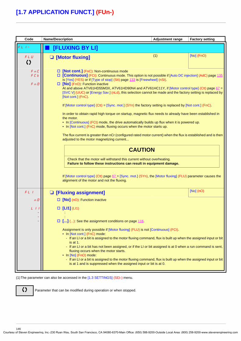
Courtes
[1.7 APPLICATION FUNCT.] (FUn-)
(1)The parameter can also be accessed in the [1.3 SETTINGS] (SEt-) menu.
Code Name/Description Adjustment range Factory setting
FLI- b [FLUXING BY LI]FLU M [Motor fluxing] (1) [No] (FnO)
FnC
FCt
FnO
v [Not cont.] (FnC): Non-continuous modev [Continuous] (FCt): Continuous mode. This option is not possible if [Auto DC injection] (AdC) page 135
is [Yes] (YES) or if [Type of stop] (Stt) page 133 is [Freewheel] (nSt).v [No] (FnO): Function inactive
At and above ATV61HD55M3X, ATV61HD90N4 and ATV61HC11Y, if [Motor control type] (Ctt) page 67 = [SVC V] (UUC) or [Energy Sav.] (nLd), this selection cannot be made and the factory setting is replaced by [Not cont.] (FnC).
If [Motor control type] (Ctt) = [Sync. mot.] (SYn) the factory setting is replaced by [Not cont.] (FnC).
In order to obtain rapid high torque on startup, magnetic flux needs to already have been established in the motor.• In [Continuous] (FCt) mode, the drive automatically builds up flux when it is powered up.• In [Not cont.] (FnC) mode, fluxing occurs when the motor starts up.
The flux current is greater than nCr (configured rated motor current) when the flux is established and is then adjusted to the motor magnetizing current...
If [Motor control type] (Ctt) page 67 = [Sync. mot.] (SYn), the [Motor fluxing] (FLU) parameter causes the alignment of the motor and not the fluxing.
FLI M [Fluxing assignment] [No] (nO)
nO
LI1
-
-
-
v [No] (nO): Function inactive
v [LI1] (LI1) : :
v [...] (...): See the assignment conditions on page 116.
Assignment is only possible if [Motor fluxing] (FLU) is not [Continuous] (FCt).• In [Not cont.] (FnC) mode:
- If an LI or a bit is assigned to the motor fluxing command, flux is built up when the assigned input or bit is at 1.
- If an LI or a bit has not been assigned, or if the LI or bit assigned is at 0 when a run command is sent, fluxing occurs when the motor starts.
• In [No] (FnO) mode:- If an LI or a bit is assigned to the motor fluxing command, flux is built up when the assigned input or bit
is at 1 and is suppressed when the assigned input or bit is at 0.
Parameter that can be modified during operation or when stopped.
CAUTIONCheck that the motor will withstand this current without overheating.Failure to follow these instructions can result in equipment damage.
146y of Steven Engineering, Inc.-230 Ryan Way, South San Francisco, CA 94080-6370-Main Office: (650) 588-9200-Outside Local Area: (800) 258-9200-www.stevenengineering.com

Courtes
[1.7 APPLICATION FUNCT.] (FUn-)
PID regulatorBlock diagramThe function is activated by assigning an analog input to the PID feedback (measurement).
PID feedback:The PID feedback must be assigned to one of the analog inputs AI1 to AI4, to the frequency input or the encoder, according to whether any extension cards have been inserted.
PID reference: The PID reference must be assigned to the following parameters:
• Preset references via logic inputs (rP2, rP3, rP4)• In accordance with the configuration of [Act. internal PID ref.] (PII) pages 151:
- Internal reference (rPI) or- Reference A (Fr1 or Fr1b, see page 111)
Combination table for preset PID references
A predictive speed reference can be used to initialize the speed on restarting the process.
How the various ramps work:• ACC and dEC are only active in the event of changes in the predictive reference and not on starting PID regulation.• AC2 affects the PID output on starting PID regulation and on PID "wake-ups" only.• PrP is only active in the event of changes in the PID reference.
LI (Pr4) LI (Pr2) Pr2 = nO reference
rPI or A
0 0 rPI or A
0 1 rP2
1 0 rP3
1 1 rP4
PAU
Pr2
Pr4
nO +
-rP2
rP3
rP4
rIGrPG
PIF
PIN
0
tLS
rSLUPP
PIF1 / PIF2PIP1 / PIP2
x(-1)
nO
nO
YES
PIC
nO
AI1.....
AI4
LI
+
+
POH
POL
rdG
ACC DECFPI x PSr
PII
SP2
SP16
rPI
A BnO
YES
PrP
AC2
Internal reference
Reference APages 111and 112
PID feedback
Preset PID references
Error inversion
Restart error or feedback threshold
(wake-up)
Gains
Ramps
Parameter: The black rectangle represents the factory setting assignment.
Key:
Ramp
Preset manual references
Scaling
RPEncoder
Network AI
Predictive speed reference
Manual reference
Auto/Manual
Pages 111 and
112
Ramp
147y of Steven Engineering, Inc.-230 Ryan Way, South San Francisco, CA 94080-6370-Main Office: (650) 588-9200-Outside Local Area: (800) 258-9200-www.stevenengineering.com

Courtes
[1.7 APPLICATION FUNCT.] (FUn-)
Scaling of feedback and references:• PIF1, PIF2 parameters
Can be used to scale the PID feedback (sensor range). This scale MUST be maintained for all other parameters.
• PIP1, PIP2 parameters Can be used to scale the adjustment range, i.e., the reference. The adjustment range MUST be within the sensor range. The scaling parameters must not exceed a value of 32767. To simplify setup, we recommend that you use values as close as possible to this maximum limit but remain within powers of 10 in respect of the actual values. Example (see the graph below): Adjustment of the volume in a tank, between 6 m3 and 15 m3.
- Sensor used 4-20 mA, 4.5 m3 for 4 mA, 20 m3 for 20 mA, with the result that PIF1 = 4500 and PIF2 = 20000.- Adjustment range 6 to 15 m3, with the result that PIP1 = 6000 (min. reference) and PIP2 = 15000 (max. reference).- Example references:
- rP1 (internal reference) = 9,500 - rp2 (preset reference) = 6,500 - rP3 (preset reference) = 8,000 - rP4 (preset reference) = 11,200
The [DISPLAY CONFIG.] menu can be used to customize the name of the unit displayed and its format.
Other parameters: • rSL parameter:
Can be used to set the PID error threshold, above which the PID regulator will be reactivated (wake-up) after a stop due to the max. time threshold being exceeded at low speed (tLS).
• Reversal of the direction of correction (PIC): If PIC = nO, the speed of the motor will increase when the error is positive, for example: pressure control with a compressor. If PIC = YES, the speed of the motor will decrease when the error is positive, for example: temperature control using a cooling fan.
• UPP parameter: If PIC = nO, can be used to set the PID feedback threshold, above which the PID regulator will be reactivated (wake-up) after a stop due to the max. time threshold being exceeded at low speed (tLS). If PIC = YES, can be used to set the PID feedback threshold, below which the PID regulator will be reactivated (wake-up) after a stop due to the max. time threshold being exceeded at low speed (tLS).
• The integral gain may be short-circuited by a logic input.
• An alarm on the PID feedback may be configured and indicated by a logic output.
• An alarm on the PID error may be configured and indicated by a logic output.
PID feedback
Adjustment range (reference)
PIP2 (15000)
PIP1 (6000)
PIF1 (4500)
PIF2 (20000)
148y of Steven Engineering, Inc.-230 Ryan Way, South San Francisco, CA 94080-6370-Main Office: (650) 588-9200-Outside Local Area: (800) 258-9200-www.stevenengineering.com

Courtes
[1.7 APPLICATION FUNCT.] (FUn-)
“Manual – Automatic” operation with PID This function combines the PID regulator, the preset speeds and a manual reference. Depending on the state of the logic input, the speed reference is given by the preset speeds or by a manual reference input via the PID function.
Manual reference (PIM)• Analog inputs AI1 to AI4• Frequency input• Encoder
Predictive speed reference (FPI)
• [AI1] (AI1): Analog input• [AI2] (AI2): Analog input• [AI3] (AI3): Analog input, if VW3A3202 extension card has been inserted• [AI4] (AI4): Analog input, if VW3A3202 extension card has been inserted• [RP] (PI): Frequency input, if VW3A3202 extension card has been inserted• [Encoder] (PG): Encoder input, if encoder card has been inserted• [HMI] (LCC): Graphic display terminal• [Modbus] (Mdb): Integrated Modbus• [CANopen] (CAn): Integrated CANopen• [Com. card] (nEt): Communication card (if inserted)• [Prog. card] (APP): Controller Inside card (if inserted)
Setting up the PID regulator1. Configuration in PID mode
See the diagram on page 147.
2. Perform a test in factory settings mode (in most cases, this will be sufficient). To optimize the drive, adjust rPG or rIG gradually and independently and observe the effect on the PID feedback in relation to the reference.
3. If the factory settings are unstable or the reference is incorrect
• Perform a test with a speed reference in Manual mode (without PID regulator) and with the drive on load for the speed range of the system: - In steady state, the speed must be stable and comply with the reference and the PID feedback signal must be stable. - In transient state, the speed must follow the ramp and stabilize quickly, and the PID feedback must follow the speed. If this is not the case, see the settings for the drive and/or sensor signal and wiring.
• Switch to PID mode.• Set brA to no (no auto-adaptation of the ramp).• Set the PID ramp (PrP) to the minimum permitted by the mechanism without triggering an ObF fault.• Set the integral gain (rIG) to minimum.• Leave the derivative gain (rdG) at 0.• Observe the PID feedback and the reference.• Switch the drive ON/OFF a number of times or vary the load or reference rapidly a number of times.• Set the proportional gain (rPG) in order to ascertain the best compromise between response time and stability in transient phases
(slight overshoot and 1 to 2 oscillations before stabilizing).• If the reference varies from the preset value in steady state, gradually increase the integral gain (rIG), reduce the proportional gain
(rPG) in the event of instability (pump applications), find a compromise between response time and static precision (see diagram).• Lastly, the derivative gain may permit the overshoot to be reduced and the response time to be improved, although this will make
it more difficult to obtain a compromise in terms of stability, as it depends on 3 gains.• Perform in-production tests over the whole reference range.
149y of Steven Engineering, Inc.-230 Ryan Way, South San Francisco, CA 94080-6370-Main Office: (650) 588-9200-Outside Local Area: (800) 258-9200-www.stevenengineering.com

Courtes
[1.7 APPLICATION FUNCT.] (FUn-)
The oscillation frequency depends on the system kinematics.
Parameter Rise time Overshoot Stabilization time Static errorrPG =
rIG
rdG = =
Regulated value
Proportional gain
rPG highOvershoot
Stabilization time
rPG low
Static error
Rise time
time
Integral gain
rIG high
rIG low
rdG increased
time
time
Reference
Reference
ReferencerPG and rIG correct
150y of Steven Engineering, Inc.-230 Ryan Way, South San Francisco, CA 94080-6370-Main Office: (650) 588-9200-Outside Local Area: (800) 258-9200-www.stevenengineering.com

Courtes
[1.7 APPLICATION FUNCT.] (FUn-)
(1)The parameter can also be accessed in the [1.3 SETTINGS] (SEt-) menu.(2) If a graphic display terminal is not in use, values greater than 9,999 will be displayed on the 4-digit display with a period mark after the
thousand digit, e.g., 15.65 for 15,650.
Code Name/Description Adjustment range Factory setting
PId- b [PID REGULATOR]Note: This function cannot be used with certain other functions. Follow the instructions on page 122.
PIF M [PID feedback ass.] [No] (nO)
nO
AI1
AI2
AI3
AI4
PI
PG
AIU1
v [No] (nO): Not assigned (function inactive) In this case, none of the function parameters can be accessed.v [AI1] (AI1): Analog inputv [AI2] (AI2): Analog inputv [AI3] (AI3): Analog input, if VW3A3202 extension card has been insertedv [AI4] (AI4): Analog input, if VW3A3202 extension card has been insertedv [RP] (PI): Frequency input, if VW3A3202 extension card has been insertedv [Encoder] (PG): Encoder input, if encoder card has been insertedv [Network AI] (AIU1): Virtual input via communication bus.
Note : If the equipment switches to forced local mode (see page 214), the virtual input remains frozen at the last value transmitted.
AICI M [AI net. channel] [No] (nO)
nO
Mdb
CAn
nEt
APP
The parameter can be accessed if [PID feedback ass.] (PIF) = [Network AI] (AIU1). This parameter can also be accessed in the [1.5 INPUTS / OUTPUTS CFG] (I-O-) menu.
v [No] (nO): Not assigned v [Modbus] (Mdb): Integrated Modbusv [CANopen] (CAn): Integrated CANopenv [Com. card] (nEt): Communication card (if inserted)v [Prog. card] (APP): Controller Inside card (if inserted)
PIF1 M [Min PID feedback] (1) 100
Value for minimum feedback. Adjustment range from 0 to [Max PID feedback] (PIF2) - 1 (2).
PIF2 M [Max PID feedback] (1) 1,000
Value for maximum feedback Adjustment range from [Min PID feedback] (PIF1) + 1 to 32,767 (2).
PIP1 M [Min PID reference] (1) 150
Minimum process value. Adjustment range between [Min PID feedback] (PIF1) and [Max PID feedback] (PIP2) - 1 (2).
PIP2 M [Max PID reference] (1) 900
Maximum process value Adjustment range between [Min PID reference] (PIP1) + 1 to [Max PID reference] (PIF2) (2).
PII M [Act. internal PID ref.] [No] (nO)
nO
YES
Internal PID regulator referencev [No] (nO): The PID regulator reference is given by Fr1 or Fr1b with summing/subtraction/multiplication
functions (see the diagram on page 110).v [Yes] (YES): The PID regulator reference is internal via parameter rPI.
rPI M [Internal PID ref.] 150
Internal PID regulator reference This parameter can also be accessed in the [1.2 MONITORING] (SUP-) menu. Adjustment range between [Min PID reference] (PIP1) and [Max PID reference] (PIP2) (2).
rPG M [PID prop. gain] 0.01 to 100 1
Proportional gain
Parameter that can be modified during operation or when stopped.
151y of Steven Engineering, Inc.-230 Ryan Way, South San Francisco, CA 94080-6370-Main Office: (650) 588-9200-Outside Local Area: (800) 258-9200-www.stevenengineering.com

Courtes
[1.7 APPLICATION FUNCT.] (FUn-)
(1)The parameter can also be accessed in the [1.3 SETTINGS] (SEt-) menu.(2) If a graphic display terminal is not in use, values greater than 9,999 will be displayed on the 4-digit display with a period mark after the
thousand digit, e.g., 15.65 for 15,650.
Code Name/Description Adjustment range Factory setting
b [PID REGULATOR] (continued)
rIG M [PID integral gain] 0.01 to 100 1
Integral gain
rdG M [PID derivative gain] 0.00 to 100 0
Derivative gain
PrP M [PID ramp] (1) 0 to 99.9 s 0 s
PID acceleration/deceleration ramp, defined to go from [Min PID reference] (PIP1) to [Max PID reference] (PIP2) and vice versa.
PIC M [PID correct. reverse] [No] (nO)
nO
YES
v [No] (nO)v [Yes] (YES)
Reversal of the direction of correction (PIC): If PIC = nO, the speed of the motor will increase when the error is positive. Example: pressure control with a compressor. If PIC = YES, the speed of the motor will decrease when the error is positive. Example: temperature control using a cooling fan.
POL M [Min PID output] (1) - 500 to 500 or -1,000 to 1,000 Hz according to rating
0 Hz
Minimum value of regulator output in Hz
POH M [Max PID output] (1) 0 to 500 or 1,000 Hz according to rating
60 Hz
Maximum value of regulator output in Hz
PAL M [Min fbk alarm] (1) 100
Minimum regulator feedback monitoring threshold (alarm can be assigned to a relay or a logic output, page 94).Adjustment range from [Min PID feedback] (PIF1) to [Max PID feedback] (PIF2) (2).
PAH M [Max fbk alarm] (1) 1,000
Maximum regulator feedback monitoring threshold (alarm can be assigned to a relay or a logic output, page 94).Adjustment range from [Min PID feedback] (PIF1) to [Max PID feedback] (PIF2) (2).
PEr M [PID error Alarm] (1) 0 to 65,535 (2) 100
Regulator error monitoring threshold.
PIS M [PID integral reset] [No] (nO)
nO
LI1
-
-
-
v [No] (nO): Function inactivev [LI1] (LI1)
: :
v [...] (...): See the assignment conditions on page 116.If the assigned input or bit is at 0, the function is inactive (the PID integral is enabled).If the assigned input or bit is at 1, the function is active (the PID integral is disabled).
Parameter that can be modified during operation or when stopped.
152y of Steven Engineering, Inc.-230 Ryan Way, South San Francisco, CA 94080-6370-Main Office: (650) 588-9200-Outside Local Area: (800) 258-9200-www.stevenengineering.com

Courtes
[1.7 APPLICATION FUNCT.] (FUn-)
(1)The parameter can also be accessed in the [1.3 SETTINGS] (SEt-) menu.(2)Range 0.01 to 99.99 s or 0.1 to 999.9 s or 1 to 9000 s according to [Ramp increment] (Inr) page 129.
Code Name/Description Adjustment range Factory setting
b [PID REGULATOR] (continued)
FPI M [Speed ref. assign.] [No] (nO)
nO
AI1
AI2
AI3
AI4
LCC
Mdb
CAn
nEt
APP
PI
PG
PID regulator predictive speed inputv [No] (nO): Not assigned (function inactive)v [AI1] (AI1): Analog inputv [AI2] (AI2): Analog inputv [AI3] (AI3): Analog input, if VW3A3202 extension card has been insertedv [AI4] (AI4): Analog input, if VW3A3202 extension card has been insertedv [HMI] (LCC): Graphic display terminalv [Modbus] (Mdb): Integrated Modbusv [CANopen] (CAn): Integrated CANopenv [Com. card] (nEt): Communication card (if inserted)v [Prog. card] (APP): Controller Inside card (if inserted)v [RP] (PI): Frequency input, if VW3A3202 extension card has been insertedv [Encoder] (PG): Encoder input, if encoder card has been inserted
PSr M [Speed input%] (1) 1 to 100% 100%
Multiplying coefficient for predictive speed input.The parameter cannot be accessed if [Speed ref. assign.] (FPI) = [No] (nO).
PAU M [Auto/Manual assign.] [No] (nO)
nO
LI1
-
-
-
v [No] (nO): The PID is always active.v [LI1] (LI1)
: :
v [...] (...): See the assignment conditions on page 116.If the assigned input or bit is at 0, the PID is active.If the assigned input or bit is at 1, manual operation is active.
AC2 M [Acceleration 2] (1) 0.01 to 9000 s (2) 5.0 s
Time to accelerate from 0 to the [Rated motor freq.] (FrS). Make sure that this value is compatible with the inertia being driven. Ramp AC2 is only active when the PID function is starting up and in the event of PID "wake-ups".
PIM M [Manual reference] [No] (nO)
nO
AI1
AI2
AI3
AI4
PI
PG
Manual speed input. The parameter can be accessed if [Auto/Manual assign.] (PAU) is not [No] (nO).v [No] (nO): Not assigned (function inactive)v [AI1] (AI1): Analog inputv [AI2] (AI2): Analog inputv [AI3] (AI3): Analog input, if VW3A3202 extension card has been insertedv [AI4] (AI4): Analog input, if VW3A3202 extension card has been insertedv [RP] (PI): Frequency input, if VW3A3202 extension card has been insertedv [Encoder] (PG): Encoder input, if encoder card has been inserted
The preset speeds are active on the manual reference if they have been configured.
Parameter that can be modified during operation or when stopped.
153y of Steven Engineering, Inc.-230 Ryan Way, South San Francisco, CA 94080-6370-Main Office: (650) 588-9200-Outside Local Area: (800) 258-9200-www.stevenengineering.com
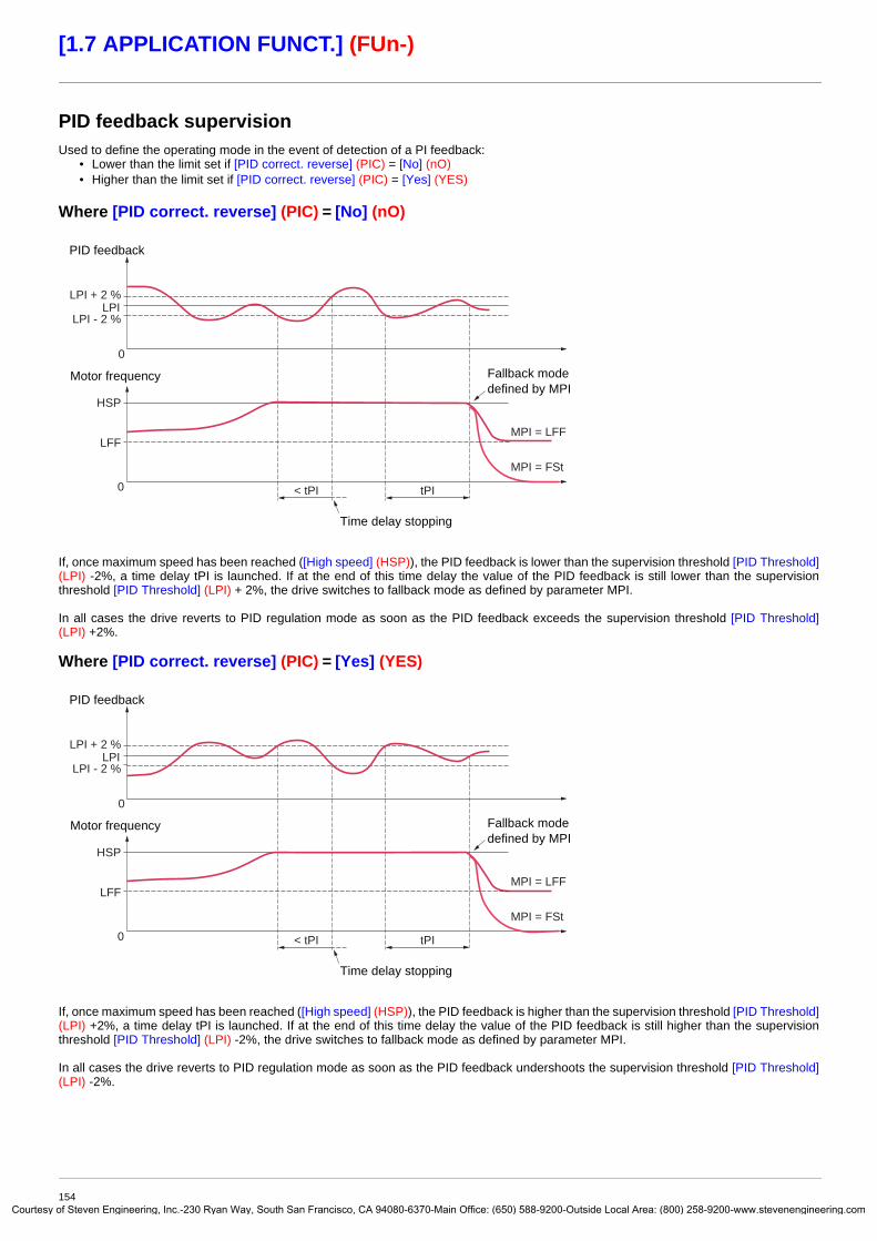
Courtes
[1.7 APPLICATION FUNCT.] (FUn-)
PID feedback supervisionUsed to define the operating mode in the event of detection of a PI feedback:
• Lower than the limit set if [PID correct. reverse] (PIC) = [No] (nO)• Higher than the limit set if [PID correct. reverse] (PIC) = [Yes] (YES)
Where [PID correct. reverse] (PIC) = [No] (nO)
If, once maximum speed has been reached ([High speed] (HSP)), the PID feedback is lower than the supervision threshold [PID Threshold](LPI) -2%, a time delay tPI is launched. If at the end of this time delay the value of the PID feedback is still lower than the supervision threshold [PID Threshold] (LPI) + 2%, the drive switches to fallback mode as defined by parameter MPI.
In all cases the drive reverts to PID regulation mode as soon as the PID feedback exceeds the supervision threshold [PID Threshold](LPI) +2%.
Where [PID correct. reverse] (PIC) = [Yes] (YES)
If, once maximum speed has been reached ([High speed] (HSP)), the PID feedback is higher than the supervision threshold [PID Threshold](LPI) +2%, a time delay tPI is launched. If at the end of this time delay the value of the PID feedback is still higher than the supervision threshold [PID Threshold] (LPI) -2%, the drive switches to fallback mode as defined by parameter MPI.
In all cases the drive reverts to PID regulation mode as soon as the PID feedback undershoots the supervision threshold [PID Threshold](LPI) -2%.
LPI + 2 %LPI
LPI - 2 %
HSP
LFFMPI = LFF
MPI = FSt
< tPI tPI0
0Fallback mode defined by MPI
Time delay stopping
PID feedback
Motor frequency
LPI + 2 %LPI
LPI - 2 %
HSP
LFFMPI = LFF
MPI = FSt
< tPI tPI0
0Fallback mode defined by MPI
Time delay stopping
PID feedback
Motor frequency
154y of Steven Engineering, Inc.-230 Ryan Way, South San Francisco, CA 94080-6370-Main Office: (650) 588-9200-Outside Local Area: (800) 258-9200-www.stevenengineering.com

Courtes
[1.7 APPLICATION FUNCT.] (FUn-)
(1)The parameter can also be accessed in the [1.3 SETTINGS] (SEt-) menu.(2) If a graphic display terminal is not in use, values greater than 9,999 will be displayed on the 4-digit display with a period mark after the
thousand digit, e.g., 15.65 for 15,650.(3)Because, in this case, the fault does not trigger a stop, it is essential to assign a relay or logic output to its indication.
Code Name/Description Adjustment range Factory setting
b [PID REGULATOR] (continued)
LPI M [PID Threshold] (1) 100
nO
-
PID regulator feedback supervision threshold (alarm can be assigned to a relay or a logic output, page 94).Adjustment range:
v [No] (nO): Function inactive (it will not be possible to access the other function parameters)v between [Min PID feedback] (PIF1) and [Max PID feedback] (PIF2) (2).
tPI M [PID Ctrl. time delay] (1) 0 to 600 s 0 s
PID regulator feedback supervision time delay
MPI M [PID Control Mngmt] [Ignore] (nO)
nO
YES
LFF
rMP
FSt
Type of stop for PID regulator feedback supervision fault.v [Ignore] (nO): Fault ignoredv [Freewheel] (YES): Freewheel stop.v [fallback spd] (LFF): Switch to fallback speed, maintained as long as the fault is present and the run
command is not disabled (3).v [Ramp stop] (rMP): Stop on rampv [Fast stop] (FSt): Fast stop
LFF M [Fallback speed] 0 to 500 or 1,000 Hz according to rating
0 Hz
Fallback speed for PID regulator feedback supervision fault.
Parameter that can be modified during operation or when stopped.
155y of Steven Engineering, Inc.-230 Ryan Way, South San Francisco, CA 94080-6370-Main Office: (650) 588-9200-Outside Local Area: (800) 258-9200-www.stevenengineering.com

Courtes
[1.7 APPLICATION FUNCT.] (FUn-)
(1)The parameter can also be accessed in the [1.3 SETTINGS] (SEt-) menu.(2) If a graphic display terminal is not in use, values greater than 9,999 will be displayed on the 4-digit display with a period mark after the
thousand digit, e.g., 15.65 for 15,650.
Code Name/Description Adjustment range Factory setting
Pr1- b [PID PRESET REFERENCES]Function can be accessed if [PID feedback ass.] (PIF) is assigned.
Pr2 M [2 preset PID ref.] [No] (nO)
nO
LI1
-
-
-
v [No] (nO): Function inactivev [LI1] (LI1)
: :
v [...] (...): See the assignment conditions on page 116.If the assigned input or bit is at 0, the function is inactive.If the assigned input or bit is at 1, the function is active.
Pr4 M [4 preset PID ref.] [No] (nO)
nO
LI1
-
-
-
Make sure that [2 preset PID ref.] (Pr2) has been assigned before assigning this function.v [No] (nO): Function inactivev [LI1] (LI1)
: :
v [...] (...): See the assignment conditions on page 116.If the assigned input or bit is at 0, the function is inactive.If the assigned input or bit is at 1, the function is active.
rP2 M [Preset ref. PID 2] (1) 300
The parameter can be accessed if [2 preset PID ref.] (Pr2) has been assigned.Adjustment range between [Min PID reference] (PIP1) and [Max PID reference] (PIP2) (2).
rP3 M [Preset ref. PID 3] (1) 600
The parameter can be accessed if [2 preset PID ref.] (Pr2) and [4 preset PID ref.] (Pr4) have been assigned.Adjustment range between [Min PID reference] (PIP1) and [Max PID reference] (PIP2) (2).
rP4 M [Preset ref. PID 4] (1) 900
The parameter can be accessed if [2 preset PID ref.] (Pr2) and [4 preset PID ref.] (Pr4) have been assigned.Adjustment range between [Min PID reference] (PIP1) and [Max PID reference] (PIP2) (2).
Parameter that can be modified during operation or when stopped.
156y of Steven Engineering, Inc.-230 Ryan Way, South San Francisco, CA 94080-6370-Main Office: (650) 588-9200-Outside Local Area: (800) 258-9200-www.stevenengineering.com

Courtes
[1.7 APPLICATION FUNCT.] (FUn-)
Sleep/Wake-upThis function supplements the PID regulator, in order to avoid prolonged operation at excessively low speeds when neither useful nor desirable.
• It stops the motor after a period of operation at reduced speed. This time and speed can be adjusted.• It restarts the motor if the PID error or feedback exceeds an adjustable threshold.
Sleep:Following operation at a speed less than [Low speed] (LSP) + [Sleep Offset Thres.] (SLE) for a period of time greater than or equal to [Low speed time out] (tLS), the motor is stopped on a ramp.
Wake-up:If the PID error exceeds [PID wake up thresh.] (rSL)(see the example opposite) or if the PID feedback exceeds [PID Wakeup Thres.] (UPP), the PID regulator is reactivated.
tLS0
0
LSPLSP + SLE
rSL
Frequency
PID error
Sleep
Wake-up
Time
Time
157y of Steven Engineering, Inc.-230 Ryan Way, South San Francisco, CA 94080-6370-Main Office: (650) 588-9200-Outside Local Area: (800) 258-9200-www.stevenengineering.com

Courtes
[1.7 APPLICATION FUNCT.] (FUn-)
(1)The parameter can also be accessed in the [1.3 SETTINGS] (SEt-) menu.(2) If a graphic display terminal is not in use, values greater than 9,999 will be displayed on the 4-digit display with a period mark after the
thousand digit, e.g., 15.65 for 15,650.
Code Name/Description Adjustment range Factory setting
SrM- b [SLEEPING / WAKE UP]tLS M [Low speed time out] (1) 0 to 999.9 s 0 s
Maximum operating time at [Low speed] (LSP).Following operation at LSP for a defined period, a motor stop is requested automatically. The motor restarts if the reference exceeds (LSP + SLE) and if a run command is still present.Caution: Value 0 corresponds to an unlimited period.
Note: If [Low speed time out] (tLS) is not 0, [Type of stop] (Stt) page 133 is forced to [Ramp stop] (rMP) (only if a ramp stop can be configured).
LSP M [Low speed] (1) 0 Hz
Motor frequency at minimum reference, can be set between 0 and [High speed] (HSP) (see page 49).
SLE M [Sleep Offset Thres.] (1) 0 to 500 or 1,000 Hz according to rating
1 Hz
Adjustable restart threshold (offset) following a stop after prolonged operation at [Low speed] (LSP), in Hz. The motor restarts if the reference rises above (LSP + SLE) and if a run command is still present.
rSL M [PID wake up thresh.] 0
If the “PID” and “Low speed operating time” tLS functions are configured at the same time, the PID regulator may attempt to set a speed lower than LSP.This results in unsatisfactory operation, which consists of starting, operating at low speed then stopping, and so on…Parameter rSL (restart error threshold) can be used to set a minimum PID error threshold for restarting after a stop at prolonged LSP.The function is inactive if the PID function has not been configured or if tLS = 0 or if rSL = 0.
Adjustment range from 0.0 to [Max PID feedback] (PIF2) (2).
Parameter that can be modified during operation or when stopped.
WARNINGUNINTENDED EQUIPMENT OPERATIONCheck that unintended restarts will not present any danger.Failure to follow these instructions can result in death or serious injury.
158y of Steven Engineering, Inc.-230 Ryan Way, South San Francisco, CA 94080-6370-Main Office: (650) 588-9200-Outside Local Area: (800) 258-9200-www.stevenengineering.com

Courtes
[1.7 APPLICATION FUNCT.] (FUn-)
(1) If a graphic display terminal is not in use, values greater than 9,999 will be displayed on the 4-digit display with a period mark after the thousand digit, e.g., 15.65 for 15,650.
Code Name/Description Adjustment range Factory setting
UPP M [PID Wakeup Thres.] [No] (nO)
If the “PID” and “Low speed operating time” tLS functions are configured at the same time, the PID regulator may attempt to set a speed lower than LSP.This results in unsatisfactory operation, which consists of starting, operating at low speed then stopping, and so on…Parameter UPP (restart feedback threshold) can be used to set a PID feedback threshold for restarting after a stop due to prolonged LSP. This threshold is minimum if [PID correct. reverse] (PIC) = [No] (nO) and maximum if [PID correct. reverse] (PIC) = [Yes] (YES)The function is inactive if the PID function has not been configured or if tLS = 0 or if UPP = [No] (nO) or if rSL is active (not 0).
Adjustment range: [No] (nO) or between [Min PID feedback] (PIF1) and [Max PID feedback] (PIF2) (2).
WARNINGUNINTENDED EQUIPMENT OPERATIONCheck that unintended restarts will not present any danger.Failure to follow these instructions can result in death or serious injury.
159y of Steven Engineering, Inc.-230 Ryan Way, South San Francisco, CA 94080-6370-Main Office: (650) 588-9200-Outside Local Area: (800) 258-9200-www.stevenengineering.com

Courtes
[1.7 APPLICATION FUNCT.] (FUn-)
Sleeping on the basis of flow detectionParameters can be accessed in [Expert] mode.
This function is only active when the motor frequency is less than [NoFlo.Freq.Thres.Ac.] (FFd).This function is used in applications where zero flow cannot be detected by the sleep function alone. At periodic intervals (based on time [No Flow Period Det.] (nFd)), it forces the drive’s frequency reference to [Low speed] (LSP) + [No Flow Offset] (LFd) in order to test for zero flow.
Set the sleep function so that the drive switches to sleep mode when zero flow is detected ([No Flow Offset] (LFd) y [Sleep Offset Thres.] (SLE) page 158).
The test can be carried out at underpressure or overpressure as appropriate for the type of installation.
Test at underpressure: (LSP + LFd) < FFd• If the request is still present, the PID regulator error increases (at underpressure), causing the drive to restart at its previous speed
above the sleep threshold..
• If the request is no longer present (zero flow), the PID regulator error will not increase, and the speed will remain below the sleep threshold, thereby inducing a stop.
.
PI feedback
Frequency
FFd
LSP + LFd
nFdLSP t
t
nFd
PID error
LSP + SLE
PID feedback
Frequency
LSPLSP + LFd
nFd tLS
FFdSleep threshold LSP + SLE
t
t
160y of Steven Engineering, Inc.-230 Ryan Way, South San Francisco, CA 94080-6370-Main Office: (650) 588-9200-Outside Local Area: (800) 258-9200-www.stevenengineering.com

Courtes
[1.7 APPLICATION FUNCT.] (FUn-)
Test at overpressure: (LSP + LFd) > FFd• If the request is still present, the PID regulator error increases (at overpressure), causing the drive to decelerate. If flow is detected,
the speed will stabilize at its previous level, above the sleep threshold..
• If the request is no longer present (zero flow), the PID regulator error increases (at overpressure), causing the drive to decelerate. The absence of flow maintains the overpressure and the speed falls below the sleep threshold, causing the drive to stop.
.
PI feedback
Frequency
FFd
LSP + LFd
nFdLSP t
t
nFd
PID error
LSP + SLE
PID feedback
Frequency
LSP
LSP + LFd
nFd tLS
FFdSleep threshold LSP + SLE
t
t
161y of Steven Engineering, Inc.-230 Ryan Way, South San Francisco, CA 94080-6370-Main Office: (650) 588-9200-Outside Local Area: (800) 258-9200-www.stevenengineering.com
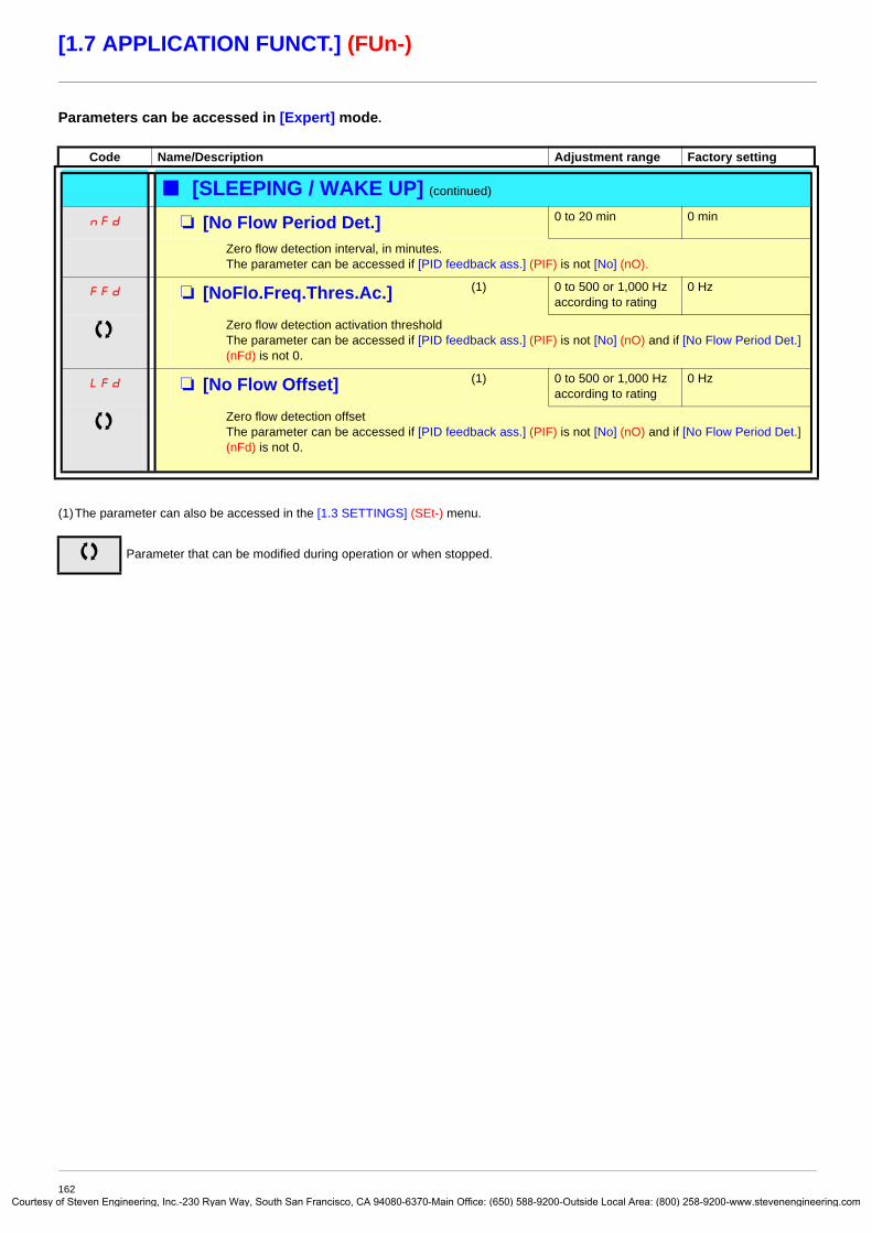
Courtes
[1.7 APPLICATION FUNCT.] (FUn-)
Parameters can be accessed in [Expert] mode.
(1)The parameter can also be accessed in the [1.3 SETTINGS] (SEt-) menu.
Code Name/Description Adjustment range Factory setting
b [SLEEPING / WAKE UP] (continued)
nFd M [No Flow Period Det.] 0 to 20 min 0 min
Zero flow detection interval, in minutes.The parameter can be accessed if [PID feedback ass.] (PIF) is not [No] (nO).
FFd M [NoFlo.Freq.Thres.Ac.] (1) 0 to 500 or 1,000 Hz according to rating
0 Hz
Zero flow detection activation thresholdThe parameter can be accessed if [PID feedback ass.] (PIF) is not [No] (nO) and if [No Flow Period Det.] (nFd) is not 0.
LFd M [No Flow Offset] (1) 0 to 500 or 1,000 Hz according to rating
0 Hz
Zero flow detection offsetThe parameter can be accessed if [PID feedback ass.] (PIF) is not [No] (nO) and if [No Flow Period Det.] (nFd) is not 0.
Parameter that can be modified during operation or when stopped.
162y of Steven Engineering, Inc.-230 Ryan Way, South San Francisco, CA 94080-6370-Main Office: (650) 588-9200-Outside Local Area: (800) 258-9200-www.stevenengineering.com

Courtes
[1.7 APPLICATION FUNCT.] (FUn-)
Torque limitationThere are two types of torque limitation:
• With a value that is fixed by a parameter• With a value that is set by an analog input (AI, pulse or encoder)
If both types are enabled, the lowest value is taken into account. The two types of limitation can be configured or switched remotely using a logic input or via the communication bus.
[Yes](YES)
LI
[Motoring torque lim] (tLIM)
[Gen. torque lim] (tLIG)
Torque limitation via parameter
[Torque limit. activ.] (tLA)
[No](nO)
[LI]
[Yes](YES)
LI
[AI.] (AI.)
[RP] (PI)[Encoder] (PG)
Torque limitation via analog input, RP or Encoder
[Analog limit. act.] (tLC)
[No](nO)
[LI]
Lowest value taken into account
Limitation value
[Torque ref. assign.] (tAA)
[AI]
163y of Steven Engineering, Inc.-230 Ryan Way, South San Francisco, CA 94080-6370-Main Office: (650) 588-9200-Outside Local Area: (800) 258-9200-www.stevenengineering.com

Courtes
[1.7 APPLICATION FUNCT.] (FUn-)
(1)The parameter can also be accessed in the [1.3 SETTINGS] (SEt-) menu.
Code Name/Description Adjustment range Factory setting
tOL- b [TORQUE LIMITATION]This function cannot be accessed in V/F profile mode.
tLA M [Torque limit. activ.] [No] (nO)
nO
YES
LI1
-
-
-
v [No] (nO): Function inactivev [Yes] (YES): Function always activev [LI1] (LI1)
: :
v [...] (...): See the assignment conditions on page 116.If the assigned input or bit is at 0, the function is inactive.If the assigned input or bit is at 1, the function is active.
IntP M [Torque increment] [1%] (1)
0.1
1
The parameter cannot be accessed if [Torque limit. activ.] (tLA) = [No] (nO). Selection of units for the [Motoring torque lim] (tLIM) and [Gen. torque lim] (tLIG) parameters
v [0.1%] (0.1): 0.1% unitv [1%] (1): 1% unit
tLIM M [Motoring torque lim] (1) 0 to 300% 100%
The parameter cannot be accessed if [Torque limit. activ.] (tLA) = [No] (nO)Torque limitation in motor mode, as a whole % or in 0.1% increments of the rated torque in accordance with the [Torque increment] (IntP) parameter.
tLIG M [Gen. torque lim] (1) 0 to 300% 100%
The parameter cannot be accessed if [Torque limit. activ.] (tLA) = [No] (nO)Torque limitation in generator mode, as a whole % or in 0.1% increments of the rated torque in accordance with the [Torque increment] (IntP) parameter.
tAA M [Torque ref. assign.] [No] (nO)
nO
AI1
-
AI4
PI
PG
AIU1
If the function is assigned, the limitation varies between 0% and 300% of the rated torque on the basis of the 0% to 100% signal applied to the assigned input.Examples:
- 12 mA on a 4-20 mA input results in limitation to 150% of the rated torque.- 2.5 V on a 10 V input results in 75% of the rated torque.
v [No] (nO): Not assigned (function inactive)v [AI1] (AI1)
to [AI4] (AI4): Analog input, if VW3A3202 I/O card has been inserted
v [RP] (PI): Frequency input, if VW3A3202 I/O card has been insertedv [Encoder] (PG): Encoder input, if encoder card has been insertedv [Network AI] (AIU1): Virtual input via communication bus, to be configured via [AI net. channel] (AIC1)
page 89
Parameter that can be modified during operation or when stopped.
WARNINGUNINTENDED EQUIPMENT OPERATIONIf the equipment switches to forced local mode (see page 214), the virtual input remains frozen at the last value transmitted.Do not use the virtual input and forced local mode in the same configuration.Failure to follow this instruction can result in death or serious injury.
164y of Steven Engineering, Inc.-230 Ryan Way, South San Francisco, CA 94080-6370-Main Office: (650) 588-9200-Outside Local Area: (800) 258-9200-www.stevenengineering.com

Courtes
[1.7 APPLICATION FUNCT.] (FUn-)
Code Name/Description Adjustment range Factory setting
tLC M [Analog limit. act.] [Yes] (YES)
YES
LI1
-
-
-
The parameter can be accessed if [Torque ref. assign.] (tAA) is not [No] (nO).v [Yes] (YES): The limitation depends on the input assigned by [Torque ref. assign.] (tAA).v [LI1] (LI1)
: :
v [...] (...): See the assignment conditions on page 116.If the assigned input or bit is at 0:• The limit is specified by the [Motoring torque lim] (tLIM) and [Gen. torque lim] (tLIG) parameters if
[Torque limit. activ.] (tLA) is not [No] (nO).• No limitation if [Torque limit. activ.] (tLA) = [No] (nO).If the assigned input or bit is at 1:• The limitation depends on the input assigned by [Torque ref. assign.] (tAA). Note: If [Torque limitation] (tLA) and [Torque ref. assign.] (tAA) are enabled at the same time, the lowest value will be taken into account.
165y of Steven Engineering, Inc.-230 Ryan Way, South San Francisco, CA 94080-6370-Main Office: (650) 588-9200-Outside Local Area: (800) 258-9200-www.stevenengineering.com

Courtes
[1.7 APPLICATION FUNCT.] (FUn-)
(1)The parameter can also be accessed in the [1.3 SETTINGS] (SEt-) menu.(2) In corresponds to the rated drive current indicated in the Installation Manual and on the drive nameplate.
Code Name/Description Adjustment range Factory setting
CLI- b [2nd CURRENT LIMIT.]LC2 M [Current limit 2] [No] (nO)
nO
LI1
-
-
-
v [No] (nO): Function inactive.v [LI1] (LI1)
: :
v [...] (...): See the assignment conditions on page 116.If the assigned input or bit is at 0, the first current limitation is active.If the assigned input or bit is at 1, the second current limitation is active.
CL2 M [I Limit. 2 value] (1) 0 to 1.1 or 1.2 In (2) according to rating
1.1 or 1.2 In (2) according to rating
Second current limitation The parameter can be accessed if [Current limit 2] (LC2) is not [No] (nO).
Note: If the setting is less than 0.25 In, the drive may lock in [Output Phase Loss] (OPF) fault mode if this has been enabled (see page 192). If it is less than the no-load motor current, the limitation no longer has any effect.
CLI M [Current Limitation] (1) 0 to 1.1 or 1.2 In (2) according to rating
1.1 or 1.2 In (2) according to rating
First current limitation
Note: If the setting is less than 0.25 In, the drive may lock in [Output Phase Loss] (OPF) fault mode if this has been enabled (see page 192). If it is less than the no-load motor current, the limitation no longer has any effect.
Parameter that can be modified during operation or when stopped.
CAUTIONCheck that the motor will withstand this current, particularly in the case of permanent magnet synchronous motors, which are susceptible to demagnetization.Failure to follow this instruction can result in equipment damage.
CAUTIONCheck that the motor will withstand this current, particularly in the case of permanent magnet synchronous motors, which are susceptible to demagnetization.Failure to follow this instruction can result in equipment damage.
166y of Steven Engineering, Inc.-230 Ryan Way, South San Francisco, CA 94080-6370-Main Office: (650) 588-9200-Outside Local Area: (800) 258-9200-www.stevenengineering.com

Courtes
[1.7 APPLICATION FUNCT.] (FUn-)
Line contactor commandExample circuit:
Note: The “Run/Reset” button must be pressed once the “Emergency stop” button has been released.
The drive control power supply must be provided via an external 24 V source.
Note: The line contactor closes every time a run command (forward or reverse) is sent and opens after every stop.
U V W
L1 L2 L3
P24 LIn LO/Rp0 LIp
0 V 24 V
ATV 71
M 3
KM1K11
K10K11
K11
K10
3 aline
Emergency stop
Run/Reset
24 V power supply
Forward or
reverse
CAUTIONThis function can only be used for a small number of consecutive operations with a cycle time longer than 60 s (in order to avoid premature aging of the filter capacitor charging circuit).
Failure to follow these instructions can result in equipment damage.
167y of Steven Engineering, Inc.-230 Ryan Way, South San Francisco, CA 94080-6370-Main Office: (650) 588-9200-Outside Local Area: (800) 258-9200-www.stevenengineering.com

Courtes
[1.7 APPLICATION FUNCT.] (FUn-)
Code Name/Description Adjustment range Factory setting
LLC- b [LINE CONTACTOR COMMAND]LLC M [Line contactor ass.] [No] (nO)
nO
LO1
-
LO4
r2
-
r4
dO1
Logic output or control relayv [No] (nO): Function not assigned (in this case, none of the function parameters can be accessed).v [LO1] (LO1)
to [LO4] (LO4): Logic output (if one or two I/O cards have been inserted, LO1 to LO2 or LO4 can be selected).
v [R2] (r2) to [R4] (r4): Relay (selection of R2 extended to R3 or R4 if one or two I/O cards have been inserted).
v [dO1] (dO1): Analog output AO1 functioning as a logic output. Selection can be made if [AO1 assignment] (AO1) page 103 = [No] (nO).
LES M [Drive lock] [No] (nO)
nO
LI1
-
-
-
v [No] (nO): Function inactive.v [LI1] (LI1)
: :
v [...] (...): See the assignment conditions on page 116.The drive locks when the assigned input or bit changes to 0.
LCt M [Mains V. time out] 5 to 999 s 5 s
Monitoring time for closing of line contactor. If, once this time has elapsed, there is no voltage on the drive power circuit, the drive will lock with an [input contactor] (LCF) fault.
168y of Steven Engineering, Inc.-230 Ryan Way, South San Francisco, CA 94080-6370-Main Office: (650) 588-9200-Outside Local Area: (800) 258-9200-www.stevenengineering.com

Courtes
[1.7 APPLICATION FUNCT.] (FUn-)
Output contactor commandThis allows the drive to control a contactor located between the drive and the motor. The request for the contactor to close is made when a run command is sent. The request for the contactor to open is made when there is no longer any current in the motor.
Output contactor feedbackThe corresponding logic input should be at 1 when there is no run command and at 0 during operation.In the event of an inconsistency, the drive trips on an FCF2 fault if the output contactor fails to close (LIx at 1) and on an FCF1 fault if it is stuck (LIx at 0).The parameter [Time to motor run] (dbS) can be used to delay tripping in fault mode when a run command is sent and the parameter [Time to open cont.] (dAS) delays the fault when a stop command is set.
Note: Fault FCF2 (contactor failing to close) can be reset by the run command changing state from 1 to 0 (0 --> 1 --> 0 in 3-wire control).
The [Out. contactor ass.] (OCC) and [Output contact. fdbk] (rCA) functions can be used individually or together.
CAUTIONIf a DC injection braking function has been configured it should not be left operating too long in stop mode, as the contactor only opens at the end of braking.
Failure to follow these instructions can result in equipment damage.
U
KM2
M 3
KM2
K20 KM2
K20
V W 0 LOp/Rp P24 LIp
Command FeedbackATV 61
169y of Steven Engineering, Inc.-230 Ryan Way, South San Francisco, CA 94080-6370-Main Office: (650) 588-9200-Outside Local Area: (800) 258-9200-www.stevenengineering.com

Courtes
[1.7 APPLICATION FUNCT.] (FUn-)
Code Name/Description Adjustment range Factory setting
OCC- b [OUTPUT CONTACTOR CMD]OCC M [Out. contactor ass.] [No] (nO)
nO
LO1
-
LO4
r2
-
r4
dO1
Logic output or control relayv [No] (nO): Function not assigned (in this case, none of the function parameters can be accessed).v [LO1] (LO1)
to [LO4] (LO4): Logic output (if one or two I/O cards have been inserted, LO1 to LO2 or LO4 can be selected).
v [R2] (r2) to [R4] (r4): Relay (selection of R2 extended to R3 or R4 if one or two I/O cards have been inserted)
v [dO1] (dO1): Analog output AO1 functioning as a logic output. Selection can be made if [AO1 assignment] (AO1) page 103 = [No] (nO).
rCA M [Output contact. fdbk] [No] (nO)
nO
LI1
-
-
-
v [No] (nO): Function inactivev [LI1] (LI1)
: :
v [...] (...): See the assignment conditions on page 116.The motor starts up when the assigned input or bit changes to 0.
dbS M [Time to motor run] 0.05 to 60 s 0.15
Time delay for:• Motor control following the sending of a run command• Output contactor fault monitoring, if the feedback is assigned. If the contactor fails to close at the end of
the set time, the drive will lock in FCF2 fault mode.This parameter can be accessed if [Output cont.] (OCC) is assigned or if [Output contact. fdbk] (rCA) is assigned.The time delay must be greater than the closing time of the output contactor.
dAS M [Time to open cont.] 0 to 5.00 s 0.10
Time delay for output contactor opening command following motor stop.This parameter can be accessed if [Output contact. fdbk] (rCA) is assigned.The time delay must be greater than the opening time of the output contactor. If it is set to 0, the fault will not be monitored.If the contactor fails to open at the end of the set time, the drive will lock in FCF1 fault mode.
Parameter that can be modified during operation or when stopped.
170y of Steven Engineering, Inc.-230 Ryan Way, South San Francisco, CA 94080-6370-Main Office: (650) 588-9200-Outside Local Area: (800) 258-9200-www.stevenengineering.com

Courtes
[1.7 APPLICATION FUNCT.] (FUn-)
Damper controlThis function applies to the ventilation ducts. The aim is to control the opening of the duct (shutter device called a "damper") when the fan starts up.
Damper opening commandThe opening command can be assigned to a logic output or a relay via the [Damper assignment] (dAM)parameter. The damper is closed automatically when there is no longer an opening command.
Damper opening feedbackOpening is controlled by a bit or a logic input that can be assigned via the [Damper feedback] (dFb) parameter. The corresponding logic input or bit can be configured (state 0 or 1 for damper open) via the parameter [F.back dam. contact](Fbtd). When there is an inconsistency, the drive trips on a [Damper stuck] (Fd1) fault if the damper does not open and on a [Damper open] (Fd2)fault if it does not close.The parameter [Time to open damp.] (tOd) can be used to delay tripping on an opening fault when a run command is sent and the parameter [Time to close damp.] (tCd) delays the closing fault when a stop command is sent.
Example of operation with feedback at state 1 for damper open
U
M 3
V W 0 LOp/Rp P24 LIp
Control FeedbackATV 61Damper
Damper opening
FanFlow of air
Damper open contact
t
t
t
t0
t
1
0
1
0
1
0
Fan speed
Run command
Opening commandRx/LOx
Position of damperOpen
Closed
Damper open contact
tOd tCd
171y of Steven Engineering, Inc.-230 Ryan Way, South San Francisco, CA 94080-6370-Main Office: (650) 588-9200-Outside Local Area: (800) 258-9200-www.stevenengineering.com

Courtes
[1.7 APPLICATION FUNCT.] (FUn-)
Code Name/Description Adjustment range Factory setting
dAM- b [DAMPER MANAGEMENT]dAM M [Damper assignment] [No] (nO)
nO
LO1
-
LO4
r2
-
r4
dO1
Logic output or opening control relayv [No] (nO): Function not assigned (in this case, none of the function's parameters can be accessed)v [LO1] (LO1)
to [LO4] (LO4): Logic output (if one or two I/O cards have been inserted, LO1 to LO2 or LO4 can be selected)[R2] (r2) to [R4] (r4): Relay (selection of R2 extended to R3 or R4 if one or two I/O cards have been inserted)
v [dO1] (dO1): Analog output AO1 functioning as a logic output. Selection can be made if [AO1 assignment] (AO1) page 103 = [No] (nO).
dFb M [Damper feedback] [No] (nO)
nO
LI1
-
-
-
Feedback of the "damper open" informationv [No] (nO): Function inactivev [LI1] (LI1)
: :
v [...] (...) : See the assignment conditions on page 116.
Note: Before assigning damper feedback, check that the input wiring or the state of the assigned bit corresponds to the configuration of parameter [F.back dam. contact] (Fbtd) below. If it does not, the drive may immediately switch to fault mode.
tOd M [Time to open damp.] 0.05 to 300 s 60
Opening fault monitoring time delay. If the damper does not open at the end of the set time, the drive will lock in [Damper stuck] (Fd1) fault mode.The time delay must be greater than the normal opening time of the damper.
tCd M [Time to close damp.] 0.00 to 300 s 60
Closing fault monitoring time delay. If the damper does not close at the end of the set time, the drive will lock in [Damper open.] (Fd1) fault mode.If this parameter is at 0.00, the [Damper open.] (Fd2) fault is monitored only at the run command before activation of the relay or the control logic output.The time delay must be greater than the normal closing time of the damper.
Fbtd M [F.back dam. contact] [Active at 0] (SHUt)
SHUt
OPEn
This parameter defines the positive or negative logic of the input or bit assigned by [Damper feedback] (dFb).
v [Active at 0] (SHUt): The motor starts up when the assigned input or bit changes to 0.v [Active at 1] (OPEn): The motor starts up when the assigned input or bit changes to 1.
Parameter that can be modified during operation or when stopped
172y of Steven Engineering, Inc.-230 Ryan Way, South San Francisco, CA 94080-6370-Main Office: (650) 588-9200-Outside Local Area: (800) 258-9200-www.stevenengineering.com

Courtes
[1.7 APPLICATION FUNCT.] (FUn-)
Parameter set switching [PARAM. SET SWITCHING]A set of 1 to 15 parameters from the [1.3 SETTINGS] (SEt-) menu on page 47 can be selected and 2 or 3 different values assigned. These 2 or 3 sets of values can then be switched using 1 or 2 logic inputs or control word bits. This switching can be performed during operation (motor running).It can also be controlled on the basis of one or two frequency thresholds, whereby each threshold acts as a logic input (0 = threshold not attained, 1 = threshold attained).
Note: Do not modify the parameters in the [1.3 SETTINGS] (SEt-) menu, because any modifications made in this menu will be lost on the next power-up. The parameters can be adjusted during operation in the [PARAM. SET SWITCHING] (MLP-) menu, on the active configuration.
Note: Parameter set switching cannot be configured from the integrated display terminal.Parameters can only be adjusted on the integrated display terminal if the function has been configured previously via the graphic display terminal, by PowerSuite or via the bus or communication network. If the function has not been configured, the MLP- menu and the PS1-, PS2-, PS3- submenus do not appear.
Values 1 Values 2 Values 3
Parameter 1Parameter 2Parameter 3Parameter 4Parameter 5Parameter 6Parameter 7Parameter 8Parameter 9
Parameter 10Parameter 11Parameter 12Parameter 13Parameter 14Parameter 15
Parameter 1Parameter 2Parameter 3Parameter 4Parameter 5Parameter 6Parameter 7Parameter 8Parameter 9Parameter 10Parameter 11Parameter 12Parameter 13Parameter 14Parameter 15
Parameter 1Parameter 2Parameter 3Parameter 4Parameter 5Parameter 6Parameter 7Parameter 8Parameter 9Parameter 10Parameter 11Parameter 12Parameter 13Parameter 14Parameter 15
Parameter 1Parameter 2Parameter 3Parameter 4Parameter 5Parameter 6Parameter 7Parameter 8Parameter 9
Parameter 10Parameter 11Parameter 12Parameter 13Parameter 14Parameter 15
Input LI or bit or frequency threshold2 values
0 1 0 or 1
Input LI or bit or frequency threshold3 values
0 0 1
173y of Steven Engineering, Inc.-230 Ryan Way, South San Francisco, CA 94080-6370-Main Office: (650) 588-9200-Outside Local Area: (800) 258-9200-www.stevenengineering.com

Courtes
[1.7 APPLICATION FUNCT.] (FUn-)
Code Name/Description Adjustment range Factory setting
MLP- b [PARAM. SET SWITCHING]CHA1 M [2 Parameter sets] [No] (nO)
nO
FtA
F2A
LI1
-
-
-
v [No] (nO): Function inactive.v [Freq.Th.att.] (FtA): Switching via [Freq. threshold] (Ftd) page 59v [Freq. Th. 2 attain.] (F2A): Switching via [Freq. threshold 2] (Ftd) page 59v [LI1] (LI1)
: :
v [...] (...): See the assignment conditions on page 116.Switching 2 parameter sets
CHA2 M [3 Parameter sets] [No] (nO)
nO
FtA
F2A
LI1
-
-
-
v [No] (nO): Function inactive.v [Freq.Th.att.] (FtA): Switching via [Freq. threshold] (Ftd) page 59v [Freq. Th. 2 attain.] (F2A): Switching via [Freq. threshold 2] (Ftd) page 59v [LI1] (LI1)
: :
v [...] (...): See the assignment conditions on page 116.Switching 3 parameter setsNote: In order to obtain 3 parameter sets, [2 Parameter sets] must also be configured.
M [PARAMETER SELECTION]The parameter can only be accessed on the graphic display terminal if [2 Parameter sets] is not [No].Making an entry in this parameter opens a window containing all the adjustment parameters that can be accessed.Select 1 to 15 parameters using ENT (a tick then appears next to the parameter). Parameter(s) can also be deselected using ENT.Example:
PS1- M [SET 1]The parameter can be accessed if one or more parameters have been selected in [PARAMETER SELECTION].Making an entry in this parameter opens a settings window containing the selected parameters in the order in which they were selected.With the graphic display terminal:
With the integrated display terminal:Proceed as in the Settings menu using the parameters that appear.
PARAMETER SELECTION1.3 SETTINGS
Ramp increment- - - - - - - - - - - - - - - - - - - - - - - - - - -
RDY Term +0.00 Hz REMSET1
Acceleration : 9.51 sDeceleration : 9.67 sAcceleration 2 : 12.58 sDeceleration 2 : 13.45 sBegin Acc round : 2.3 s
Code T/K
ENT
RDY Term +0.00 Hz REM Acceleration
9.51 sMin = 0.1 Max = 999.9
<< >> T/K
174y of Steven Engineering, Inc.-230 Ryan Way, South San Francisco, CA 94080-6370-Main Office: (650) 588-9200-Outside Local Area: (800) 258-9200-www.stevenengineering.com

Courtes
[1.7 APPLICATION FUNCT.] (FUn-)
Note: We recommend that a parameter set switching test is carried out on stopping and a check is made to ensure that it has been performed correctly.Some parameters are interdependent and in this case may be restricted at the time of switching.
Interdependencies between parameters must be respected, even between different sets.
Example: The highest [Low speed] (LSP) must be below the lowest [High speed] (HSP).
Code Name/Description Adjustment range Factory setting
b [PARAM. SET SWITCHING] (continued)
PS2- M [SET 2]The parameter can be accessed if one or more parameters have been selected in [PARAMETER SELECTION].Procedure identical to [SET 1] (PS1-).
PS3- M [SET 3]The parameter can be accessed if [3 parameter sets] is not [No] and if one or more parameters have been selected in [PARAMETER SELECTION].Procedure identical to [SET 1] (PS1-).
175y of Steven Engineering, Inc.-230 Ryan Way, South San Francisco, CA 94080-6370-Main Office: (650) 588-9200-Outside Local Area: (800) 258-9200-www.stevenengineering.com

Courtes
[1.7 APPLICATION FUNCT.] (FUn-)
Motor or configuration switching [MULTIMOTORS/CONFIG.]The drive may contain up to 3 configurations, which can be saved using the [1.12 FACTORY SETTINGS] (FCS-) menu, page 218.Each of these configurations can be activated remotely, enabling adaptation to:
• 2 or 3 different motors or mechanisms (multimotor mode)• 2 or 3 different configurations for a single motor (multiconfiguration mode)
The two switching modes cannot be combined.Note: The following conditions MUST be observed:• Switching may only take place when stopped (drive locked). If a switching request is sent during operation, it will not be executed
until the next stop.• In the event of motor switching, the following additional conditions apply:
- When the motors are switched, the power and control terminals concerned must also be switched as appropriate.- The maximum power of the drive must not be exceeded by any of the motors.
• All the configurations to be switched must be set and saved in advance in the same hardware configuration, this being the definitive configuration (option and communication cards). Failure to follow this instruction can cause the drive to lock on an [Incorrect config.] (CFF) fault.
Menu and parameters switched in multimotor mode• [1.3 SETTINGS] (SEt-)• [1.4 MOTOR CONTROL] (drC-)• [1.5 INPUTS / OUTPUTS CFG] (I-O-)• [1.6 COMMAND] (CtL-)• [1.7 APPLICATION FUNCT.] (FUn-) with the exception of the [MULTIMOTORS/CONFIG.] function (to be configured once only)• [1.8 FAULT MANAGEMENT] (FLt)• [1.13 USER MENU] • [USER CONFIG.]: The name of the configuration specified by the user in the [1.12 FACTORY SETTINGS] (FCS-) menu
Menu and parameters switched in multiconfiguration modeAs in multimotor mode, except for the motor parameters that are common to the three configurations:
- Rated current- Thermal current- Rated voltage- Rated frequency- Rated speed- Rated power- Magnetizing current at zero frequency- IR compensation- Slip compensation- Synchronous motor parameters- Type of thermal protection- Thermal state- The auto-tuning parameters and motor parameters that can be accessed in expert mode- Type of motor control
Note: No other menus or parameters can be switched.
176y of Steven Engineering, Inc.-230 Ryan Way, South San Francisco, CA 94080-6370-Main Office: (650) 588-9200-Outside Local Area: (800) 258-9200-www.stevenengineering.com

Courtes
[1.7 APPLICATION FUNCT.] (FUn-)
Transfer of a drive configuration to another one, with graphic display terminal, when the drive uses [MULTIMOTORS/CONFIG.] functionLet A be the source drive and B the drive addressed. In this example, switching are controled by logic input.
1. Connect graphic display terminal to the drive A.2. Put logic input LI ([2 Configurations] (CnF1)) and LI ([3 Configurations] (CnF2)) to 0.3. Download configuration 0 in a file of graphic display terminal (example : file 1 of the graphic display terminal).4. Put logic input LI ([2 Configurations] (CnF1)) to 1 and leave logic input LI ([3 Configurations] (CnF2)) to 0.5. Download configuration 1 in a file of graphic display terminal (example : file 2 of the graphic display terminal).6. Put logic input LI ([3 Configurations] (CnF2)) to 1 and leave logic input LI ([2 Configurations] (CnF1)) to 1.7. Download configuration 2 in a file of graphic display terminal (example : file 3 of the graphic display terminal).8. Connect graphic display terminal to the drive B.9. Put logic input LI ([2 Configurations] (CnF1)) and LI ([3 Configurations] (CnF2)) to 0.10. Make a factory setting of the drive B.11. Download the configuration file 0 in the drive (file 1 of graphic display terminal in this example).12. Put logic input LI ([2 Configurations] (CnF1)) to 1 and leave logic input LI ([3 Configurations] (CnF2)) to 0.13. Download the configuration file 1 in the drive (file 2 of graphic display terminal in this example).14. Put logic input LI ([3 Configurations] (CnF2)) to 1 and leave logic input LI ([2 Configurations] (CnF1)) to 1.15. Download the configuration file 2 in the drive (file 3 of graphic display terminal in this example).
Nota: Steps 6, 7, 14 et 15 are necessary only if [MULTIMOTORS/CONFIG.] function is used with 3 configurations or 3 motors.
Configuration 0or motor 0
Configuration 1or motor 1
Configuration 2or motor 2
Current configuration
Graphic display terminal
Network
Terminal
CANopen
Modbus
[2 Configurations] (CnF1)[3 Configurations] (CnF2)
CnF1 = 0, CnF2 = 0 CnF1 = 1, CnF2 = 0 CnF1 = 0, CnF2 = 1or
CnF1= 1, CnF2 = 1
177y of Steven Engineering, Inc.-230 Ryan Way, South San Francisco, CA 94080-6370-Main Office: (650) 588-9200-Outside Local Area: (800) 258-9200-www.stevenengineering.com
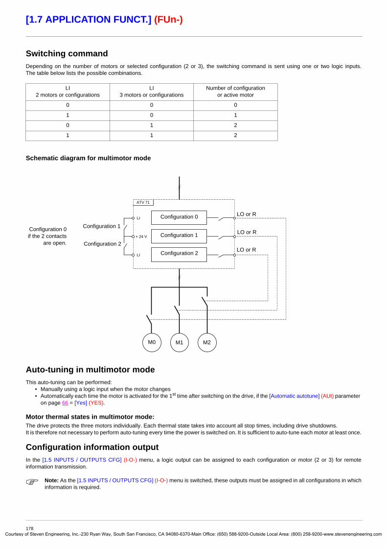
Courtes
[1.7 APPLICATION FUNCT.] (FUn-)
Switching commandDepending on the number of motors or selected configuration (2 or 3), the switching command is sent using one or two logic inputs. The table below lists the possible combinations.
Schematic diagram for multimotor mode
Auto-tuning in multimotor modeThis auto-tuning can be performed:
• Manually using a logic input when the motor changes• Automatically each time the motor is activated for the 1st time after switching on the drive, if the [Automatic autotune] (AUt) parameter
on page 66 = [Yes] (YES).
Motor thermal states in multimotor mode:The drive protects the three motors individually. Each thermal state takes into account all stop times, including drive shutdowns.It is therefore not necessary to perform auto-tuning every time the power is switched on. It is sufficient to auto-tune each motor at least once.
Configuration information outputIn the [1.5 INPUTS / OUTPUTS CFG] (I-O-) menu, a logic output can be assigned to each configuration or motor (2 or 3) for remote information transmission.
Note: As the [1.5 INPUTS / OUTPUTS CFG] (I-O-) menu is switched, these outputs must be assigned in all configurations in which information is required.
LI2 motors or configurations
LI3 motors or configurations
Number of configuration or active motor
0 0 0
1 0 1
0 1 2
1 1 2
LI
ATV 71
+ 24 V
LI
Configuration 0 if the 2 contacts
are open.
Configuration 1
Configuration 2
Configuration 0 LO or R
Configuration 1 LO or R
Configuration 2 LO or R
M0 M1 M2
178y of Steven Engineering, Inc.-230 Ryan Way, South San Francisco, CA 94080-6370-Main Office: (650) 588-9200-Outside Local Area: (800) 258-9200-www.stevenengineering.com

Courtes
[1.7 APPLICATION FUNCT.] (FUn-)
Code Name/Description Adjustment range Factory setting
MMC- b [MULTIMOTORS/CONFIG.]
CHM M [Multimotors] [No] (nO)
nO
YES
v [No] (nO): Multiconfiguration possiblev [Yes] (YES): Multimotor possible
CnF1 M [2 Configurations] [No] (nO)
nO
LI1
-
-
C111
-
-
-
v [No] (nO): No switching.v [LI1] (LI1) to [LI6] (LI6) v [LI7] (LI7) to [LI10] (LI10): If VW3A3201 logic I/O card has been insertedv [LI11] (LI11) to [LI14] (LI14): If VW3A3202 extended I/O card has been insertedv [C111] (C111) to [C115] (C115): With integrated Modbusv [C211] (C211) to [C215] (C215): With integrated CANopenv [C311] (C311) to [C315] (C315): With a communication cardv [C411] (C411) to [C415] (C415): With a Controller Inside card
Switching of 2 motors or 2 configurations
CnF2 M [3 Configurations] [No] (nO)
nO
LI1
-
-
C111
-
-
-
v [No] (nO): No switchingv [LI1] (LI1) to [LI6] (LI6) v [LI7] (LI7) to [LI10] (LI10): If VW3A3201 logic I/O card has been insertedv [LI11] (LI11) to [LI14] (LI14): If VW3A3202 extended I/O card has been insertedv [C111] (C111) to [C115] (C115): With integrated Modbusv [C211] (C211) to [C215] (C215): With integrated CANopenv [C311] (C311) to [C315] (C315): With a communication cardv [C411] (C411) to [C415] (C415): With a Controller Inside card
Switching of 3 motors or 3 configurations
Note: In order to obtain 3 motors or 3 configurations, [2 Configurations] (CnF1) must also be configured.
tnL- b [AUTO TUNING BY LI]tUL M [Auto-tune assign.] [No] (nO)
nO
LI1
-
-
-
v [No] (nO): Not assignedv [LI1] (LI1)
: :
v [...] (...): See the assignment conditions on page 116.Auto-tuning is performed when the assigned input or bit changes to 1.
Note: Auto-tuning causes the motor to start up.
179y of Steven Engineering, Inc.-230 Ryan Way, South San Francisco, CA 94080-6370-Main Office: (650) 588-9200-Outside Local Area: (800) 258-9200-www.stevenengineering.com

Courtes
[1.7 APPLICATION FUNCT.] (FUn-)
Zero fluid or zero flow detection via sensorIn the case of a pump, for example, this function can be used to avoid operation when there is no fluid or if the conduits are blocked.Although this function is independent of the “[1.7 APPLICATION FUNCT.] (FUn-)” function on page 160, the two can be used in tandem.
The function uses a fluid sensor assigned to a logic input or a bit, which can be configured for positive or negative logic by [Conf.sensor flow] (LnS).The fault is triggered if the frequency exceeds an adjustable threshold [Freq.Th.Sensor. Act.] (nFFt) and the input or bit assigned to the sensor changes to 0 or 1 depending on its configuration. The fault is ignored on startup for an adjustably time delay [Flow Times Ctrl] (nFSt) in order to avoid untimely triggering due to a transient state.
This fault triggers a freewheel stop.
Run command
Flow sensor(example where 0 = zero flow)
LSP
HSPFrequency
Test zone forzero flow
nFSt
nFFt
Zero flow (freewheel stop)
180y of Steven Engineering, Inc.-230 Ryan Way, South San Francisco, CA 94080-6370-Main Office: (650) 588-9200-Outside Local Area: (800) 258-9200-www.stevenengineering.com
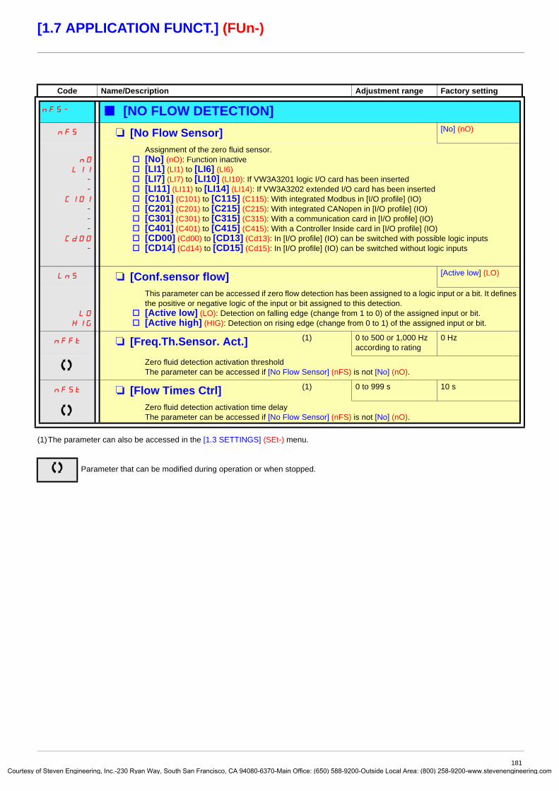
Courtes
[1.7 APPLICATION FUNCT.] (FUn-)
(1)The parameter can also be accessed in the [1.3 SETTINGS] (SEt-) menu.
Code Name/Description Adjustment range Factory setting
nFS- b [NO FLOW DETECTION] nFS M [No Flow Sensor] [No] (nO)
nO
LI1
-
-
C101
-
-
-
Cd00
-
Assignment of the zero fluid sensor.v [No] (nO): Function inactivev [LI1] (LI1) to [LI6] (LI6) v [LI7] (LI7) to [LI10] (LI10): If VW3A3201 logic I/O card has been insertedv [LI11] (LI11) to [LI14] (LI14): If VW3A3202 extended I/O card has been insertedv [C101] (C101) to [C115] (C115): With integrated Modbus in [I/O profile] (IO)v [C201] (C201) to [C215] (C215): With integrated CANopen in [I/O profile] (IO)v [C301] (C301) to [C315] (C315): With a communication card in [I/O profile] (IO)v [C401] (C401) to [C415] (C415): With a Controller Inside card in [I/O profile] (IO)v [CD00] (Cd00) to [CD13] (Cd13): In [I/O profile] (IO) can be switched with possible logic inputsv [CD14] (Cd14) to [CD15] (Cd15): In [I/O profile] (IO) can be switched without logic inputs
LnS M [Conf.sensor flow] [Active low] (LO)
LO
HIG
This parameter can be accessed if zero flow detection has been assigned to a logic input or a bit. It defines the positive or negative logic of the input or bit assigned to this detection.
v [Active low] (LO): Detection on falling edge (change from 1 to 0) of the assigned input or bit.v [Active high] (HIG): Detection on rising edge (change from 0 to 1) of the assigned input or bit.
nFFt M [Freq.Th.Sensor. Act.] (1) 0 to 500 or 1,000 Hz according to rating
0 Hz
Zero fluid detection activation thresholdThe parameter can be accessed if [No Flow Sensor] (nFS) is not [No] (nO).
nFSt M [Flow Times Ctrl] (1) 0 to 999 s 10 s
Zero fluid detection activation time delayThe parameter can be accessed if [No Flow Sensor] (nFS) is not [No] (nO).
Parameter that can be modified during operation or when stopped.
181y of Steven Engineering, Inc.-230 Ryan Way, South San Francisco, CA 94080-6370-Main Office: (650) 588-9200-Outside Local Area: (800) 258-9200-www.stevenengineering.com
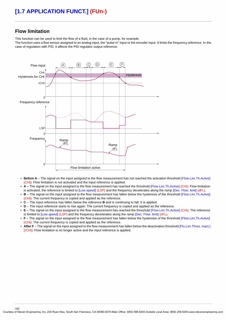
Courtes
[1.7 APPLICATION FUNCT.] (FUn-)
Flow limitationThis function can be used to limit the flow of a fluid, in the case of a pump, for example.The function uses a flow sensor assigned to an analog input, the “pulse in” input or the encoder input. It limits the frequency reference. In the case of regulation with PID, it affects the PID regulator output reference.
• Before A – The signal on the input assigned to the flow measurement has not reached the activation threshold [Flow.Lim.Th.Active] (CHt): Flow limitation is not activated and the input reference is applied.
• A – The signal on the input assigned to the flow measurement has reached the threshold [Flow.Lim.Th.Active] (CHt): Flow limitation is activated, the reference is limited to [Low speed] (LSP) and the frequency decelerates along the ramp [Dec. Flow. limit] (dFL).
• B – The signal on the input assigned to the flow measurement has fallen below the hysteresis of the threshold [Flow.Lim.Th.Active] (CHt): The current frequency is copied and applied as the reference.
• C – The input reference has fallen below the reference B and is continuing to fall: It is applied.• D – The input reference starts to rise again: The current frequency is copied and applied as the reference.• E – The signal on the input assigned to the flow measurement has reached the threshold [Flow.Lim.Th.Active] (CHt): The reference
is limited to [Low speed] (LSP) and the frequency decelerates along the ramp [Dec. Flow. limit] (dFL).• F – The signal on the input assigned to the flow measurement has fallen below the hysteresis of the threshold [Flow.Lim.Th.Active]
(CHt): The current frequency is copied and applied as the reference.• After F – The signal on the input assigned to the flow measurement has fallen below the deactivation threshold [Flo.Lim.Thres. Inact.]
(rCHt): Flow limitation is no longer active and the input reference is applied.
CHt
rCHt
LSP
A B ED FC
0
0
0
dFL
dFL
Flow input
Hysteresis for CHt Hysteresis
Flow limitation active
Frequency reference
Frequency RampRamp
182y of Steven Engineering, Inc.-230 Ryan Way, South San Francisco, CA 94080-6370-Main Office: (650) 588-9200-Outside Local Area: (800) 258-9200-www.stevenengineering.com

Courtes
[1.7 APPLICATION FUNCT.] (FUn-)
(1)The parameter can also be accessed in the [1.3 SETTINGS] (SEt-) menu.(2)Range 0.01 to 99.99 s or 0.1 to 999.9 s or 1 to 9,000 s according to [Ramp increment] (Inr) page 129.
Code Name/Description Adjustment range Factory setting
FLL- b [FLOW LIMITATION] CHI M [Flow.Sen.Inf] [No] (nO)
nO
AI1
-
AI4
PI
PG
v [No] (nO): Not assigned (function inactive)v [AI1] (AI1)
to [AI4] (AI4): Analog input, if VW3A3202 I/O card has been inserted
v [RP] (PI): Frequency input, if VW3A3202 I/O card has been insertedv [Encoder] (PG): Encoder input, if encoder card has been inserted
CHt M [Flow.Lim.Th.Active] (1) 0 to 100% 0%
The parameter can be accessed if [Flow.Sen.Inf] (CHI) is not [No] (nO).Function activation threshold, as a % of the max. signal of the assigned input
rCHt M [Flo.Lim.Thres. Inact.] (1) 0 to 100% 0%
The parameter can be accessed if [Flow.Sen.Inf] (CHI) is not [No] (nO).Function deactivation threshold, as a % of the max. signal of the assigned input
dFL M [Dec. Flow. limit] (1) 0.01 to 9,000 s (2) 5.0 s
The parameter can be accessed if [Flow.Sen.Inf] (CHI) is not [No] (nO).Time to decelerate from the [Rated motor freq.] (FrS) to 0. Make sure that this value is compatible with the inertia being driven.
Parameter that can be modified during operation or when stopped.
183y of Steven Engineering, Inc.-230 Ryan Way, South San Francisco, CA 94080-6370-Main Office: (650) 588-9200-Outside Local Area: (800) 258-9200-www.stevenengineering.com
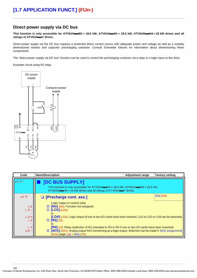
Courtes
[1.7 APPLICATION FUNCT.] (FUn-)
Direct power supply via DC busThis function is only accessible for ATV61HpppM3 u 18.5 kW, ATV61HpppN4 u 18.5 kW, ATV61WpppN4 u 22 kW drives and all ratings of ATV61HpppY drives.
Direct power supply via the DC bus requires a protected direct current source with adequate power and voltage as well as a suitably dimensioned resistor and capacitor precharging contactor. Consult Schneider Electric for information about dimensioning these components.
The “direct power supply via DC bus” function can be used to control the precharging contactor via a relay or a logic input on the drive.
Example circuit using R2 relay:
Code Name/Description Adjustment range Factory setting
dCO- b [DC BUS SUPPLY]This function is only accessible for ATV61HpppM3 u 18.5 kW, ATV61HpppN4 u 18.5 kW, ATV61WpppN4 u 22 kW drives and all ratings of ATV61HpppY drives.
dCO M [Precharge cont. ass.] [No] (nO)
nO
LO1
-
LO4
r2
-
r4
dO1
Logic output or control relayv [No] (nO): Function not assigned.v [LO1] (LO1)
to [LO4] (LO4): Logic output (if one or two I/O cards have been inserted, LO1 to LO2 or LO4 can be selected).
v [R2] (r2) to [R4] (r4): Relay (selection of R2 extended to R3 or R4 if one or two I/O cards have been inserted).
v [dO1] (dO1): Analog output AO1 functioning as a logic output. Selection can be made if [AO1 assignment] (AO1) page 103 = [No] (nO).
ATV61ppp
U /
T1
V /
T2
W /
T3
M 3 a
A1
R2A
R2C
- KM1A2
A1
U1
W1
V1
P0
PA
/+
PC
/-
- +
DC power supply
Contactor power supply
184y of Steven Engineering, Inc.-230 Ryan Way, South San Francisco, CA 94080-6370-Main Office: (650) 588-9200-Outside Local Area: (800) 258-9200-www.stevenengineering.com

Courtes
[1.8 FAULT MANAGEMENT] (FLt-)
With graphic display terminal:
With integrated display terminal: Summary of functions:
Code Name PagePtC- [PTC MANAGEMENT] 187
rSt- [FAULT RESET] 188
Atr- [AUTOMATIC RESTART] 189
FLr- [CATCH ON THE FLY] 190
tHt- [MOTOR THERMAL PROT.] 192
OPL- [OUTPUT PHASE LOSS] 192
IPL- [INPUT PHASE LOSS] 193
OHL- [DRIVE OVERHEAT] 193
SAt- [THERMAL ALARM STOP] 194
EtF- [EXTERNAL FAULT] 195
USb- [UNDERVOLTAGE MGT] 196
tIt- [IGBT TESTS] 197
LFL- [4-20mA LOSS] 198
InH- [FAULT INHIBITION] 199
CLL- [COM. FAULT MANAGEMENT] 200
tId- [TORQUE OR I LIM. DETECT.] 201
FqF- [FREQUENCY METER] 203
brP- [DB RES. PROTECTION] 204
bUF- [BU PROTECTION] 204
tnF- [AUTO TUNING FAULT] 204
PPI- [CARDS PAIRING] 205
ULd- [PROCESS UNDERLOAD] 207
OLd- [PROCESS OVERLOAD] 208
FdL- [DAMPER FAULT MGT.] 209
LFF- [FALLBACK SPEED] 210
FSt- [RAMP DIVIDER] 210
dCI- [DC INJECTION] 210
RDY Term +0.00 Hz REMMAIN MENU
1 DRIVE MENU2 ACCESS LEVEL3 OPEN / SAVE AS4 PASSWORD5 LANGUAGE
Code T/K
ENT
RDY Term +0.00 Hz REM1 DRIVE MENU
1.1 SIMPLY START1.2 MONITORING1.3 SETTINGS1.4 MOTOR CONTROL1.5 INPUTS / OUTPUTS CFG
Code << >> T/K1.6 COMMAND1.7 APPLICATION FUNCT.1.8 FAULT MANAGEMENT1.9 COMMUNICATION1.10 DIAGNOSTICS1.11 IDENTIFICATION1.12 FACTORY SETTINGS1.13 USER MENU1.14 PROGRAMMABLE CARD
ENTRUN Term +0.00 Hz REM
1.8 FAULT MANAGEMENTPTC MANAGEMENTFAULT RESETAUTOMATIC RESTARTCATCH ON THE FLYMOTOR THERMAL PROT.
Code << >> T/K
XXX
FUn-
SIM-
ESC
ESC
ESC
ENT
LAC-
CON-
FLt-
ESC
ESCENT
ESC
Displays the drive state
FAULT MANAGEMENT
Power-up
185y of Steven Engineering, Inc.-230 Ryan Way, South San Francisco, CA 94080-6370-Main Office: (650) 588-9200-Outside Local Area: (800) 258-9200-www.stevenengineering.com

Courtes
[1.8 FAULT MANAGEMENT] (FLt-)
The parameters in the [1.8 FAULT MANAGEMENT] (FLt-) menu can only be modified when the drive is stopped and there is no run command, except for parameters with a symbol in the code column, which can be modified with the drive running or stopped.
PTC probes3 sets of PTC probes can be managed by the drive in order to protect the motors:
• 1 on logic input LI6 converted for this use by switch “SW2” on the control card.• 1 on each of the 2 option cards VW3A3201 and VW3A3202.
Each of these sets of PTC probes is monitored for the following faults:
• Motor overheating• Sensor break fault• Sensor short-circuit fault
Protection via PTC probes does not disable protection via I2t calculation performed by the drive (the two types of protection can be combined).
186y of Steven Engineering, Inc.-230 Ryan Way, South San Francisco, CA 94080-6370-Main Office: (650) 588-9200-Outside Local Area: (800) 258-9200-www.stevenengineering.com

Courtes
[1.8 FAULT MANAGEMENT] (FLt-)
Code Name/Description Adjustment range Factory setting
PtC- b [PTC MANAGEMENT]PtCL M [LI6 = PTC probe] [No] (nO)
nO
AS�
rdS�
rS
Can be accessed if switch SW2 on the control card is set to PTC.v [No] (nO): Not usedv [Always] (AS): “PTC probe” faults are monitored permanently, even if the power supply is not connected
(as long as the control remains connected to the power supply).v [Power ON] (rdS): “PTC probe” faults are monitored while the drive power supply is connected.v [Motor ON] (rS): “PTC probe” faults are monitored while the motor power supply is connected.
PtC1 M [PTC1 probe] [No] (nO)
nO
AS�
rdS�
rS
Can be accessed if a VW3A3201 option card has been inserted.v [No] (nO): Not usedv [Always] (AS): “PTC probe” faults are monitored permanently, even if the power supply is not connected
(as long as the control remains connected to the power supply).v [Power ON] (rdS): “PTC probe” faults are monitored while the drive power supply is connected.v [Motor ON] (rS): “PTC probe” faults are monitored while the motor power supply is connected.
PtC2 M [PTC2 probe] [No] (nO)
nO
AS�
rdS�
rS
Can be accessed if a VW3A3202 option card has been inserted.v [No] (nO): Not usedv [Always] (AS): “PTC probe” faults are monitored permanently, even if the power supply is not connected
(as long as the control remains connected to the power supply).v [Power ON] (rdS): “PTC probe” faults are monitored while the drive power supply is connected.v [Motor ON] (rS): “PTC probe” faults are monitored while the motor power supply is connected.
187y of Steven Engineering, Inc.-230 Ryan Way, South San Francisco, CA 94080-6370-Main Office: (650) 588-9200-Outside Local Area: (800) 258-9200-www.stevenengineering.com
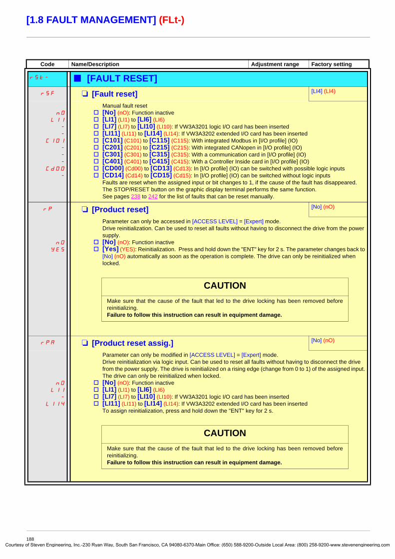
Courtes
[1.8 FAULT MANAGEMENT] (FLt-)
Code Name/Description Adjustment range Factory setting
rSt- b [FAULT RESET]rSF M [Fault reset] [LI4] (LI4)
nO
LI1
-
-
C101
-
-
-
Cd00
-
Manual fault resetv [No] (nO): Function inactivev [LI1] (LI1) to [LI6] (LI6) v [LI7] (LI7) to [LI10] (LI10): If VW3A3201 logic I/O card has been insertedv [LI11] (LI11) to [LI14] (LI14): If VW3A3202 extended I/O card has been insertedv [C101] (C101) to [C115] (C115): With integrated Modbus in [I/O profile] (IO)v [C201] (C201) to [C215] (C215): With integrated CANopen in [I/O profile] (IO)v [C301] (C301) to [C315] (C315): With a communication card in [I/O profile] (IO)v [C401] (C401) to [C415] (C415): With a Controller Inside card in [I/O profile] (IO)v [CD00] (Cd00) to [CD13] (Cd13): In [I/O profile] (IO) can be switched with possible logic inputsv [CD14] (Cd14) to [CD15] (Cd15): In [I/O profile] (IO) can be switched without logic inputs
Faults are reset when the assigned input or bit changes to 1, if the cause of the fault has disappeared.The STOP/RESET button on the graphic display terminal performs the same function.See pages 238 to 242 for the list of faults that can be reset manually.
rP M [Product reset] [No] (nO)
nO
YES
Parameter can only be accessed in [ACCESS LEVEL] = [Expert] mode.Drive reinitialization. Can be used to reset all faults without having to disconnect the drive from the power supply.
v [No] (nO): Function inactivev [Yes] (YES): Reinitialization. Press and hold down the "ENT" key for 2 s. The parameter changes back to
[No] (nO) automatically as soon as the operation is complete. The drive can only be reinitialized when locked.
rPA M [Product reset assig.] [No] (nO)
nO
LI1
-
LI14
Parameter can only be modified in [ACCESS LEVEL] = [Expert] mode.Drive reinitialization via logic input. Can be used to reset all faults without having to disconnect the drive from the power supply. The drive is reinitialized on a rising edge (change from 0 to 1) of the assigned input. The drive can only be reinitialized when locked.
v [No] (nO): Function inactivev [LI1] (LI1) to [LI6] (LI6) v [LI7] (LI7) to [LI10] (LI10): If VW3A3201 logic I/O card has been insertedv [LI11] (LI11) to [LI14] (LI14): If VW3A3202 extended I/O card has been inserted
To assign reinitialization, press and hold down the "ENT" key for 2 s.
CAUTIONMake sure that the cause of the fault that led to the drive locking has been removed before reinitializing.Failure to follow this instruction can result in equipment damage.
CAUTIONMake sure that the cause of the fault that led to the drive locking has been removed before reinitializing.Failure to follow this instruction can result in equipment damage.
188y of Steven Engineering, Inc.-230 Ryan Way, South San Francisco, CA 94080-6370-Main Office: (650) 588-9200-Outside Local Area: (800) 258-9200-www.stevenengineering.com

Courtes
[1.8 FAULT MANAGEMENT] (FLt-)
Code Name/Description Adjustment range Factory setting
Atr- b [AUTOMATIC RESTART]Atr M [Automatic restart] [No] (nO)
nO
YES
v [No] (nO): Function inactivev [Yes] (YES): Automatic restart, after locking on a fault, if the fault has disappeared and the other
operating conditions permit the restart. The restart is performed by a series of automatic attempts separated by increasingly longer waiting periods: 1 s, 5 s, 10 s, then 1 mn for the following attempts. The drive fault relay remains activated if this function is active. The speed reference and the operating direction must be maintained. Use 2-wire control ([2/3 wire control] (tCC) = [2 wire] (2C) and [2 wire type] (tCt) = [Level] (LEL) see page 80).
If the restart has not taken place once the configurable time tAr has elapsed, the procedure is aborted and the drive remains locked until it is turned off and then on again. The faults which permit this function are listed on page 241:
tAr M [Max. restart time] [5 minutes] (5)
5
10
30
1h
2h
3h
Ct
v [5 minutes] (5): 5 minutesv [10 minutes] (10): 10 minutesv [30 minutes] (30): 30 minutesv [1 hour] (1h): 1 hourv [2 hours] (2h): 2 hoursv [3 hours] (3h): 3 hoursv [Unlimited] (Ct): Unlimited
Max. duration of restart attempts. This parameter appears if [Automatic restart] (Atr) = [Yes] (YES). It can be used to limit the number of consecutive restarts on a recurrent fault.
WARNINGUNINTENDED EQUIPMENT OPERATIONCheck that an automatic restart will not endanger personnel or equipment in any way.
Failure to follow these instructions can result in death or serious injury.
189y of Steven Engineering, Inc.-230 Ryan Way, South San Francisco, CA 94080-6370-Main Office: (650) 588-9200-Outside Local Area: (800) 258-9200-www.stevenengineering.com

Courtes
[1.8 FAULT MANAGEMENT] (FLt-)
Code Name/Description Adjustment range Factory setting
FLr- b [CATCH ON THE FLY]FLr M [Catch on the fly] [Yes] (YES)
nO
YES
Used to enable a smooth restart if the run command is maintained after the following events:• Loss of line supply or disconnection• Reset of current fault or automatic restart• Freewheel stopThe speed given by the drive resumes from the estimated speed of the motor at the time of the restart, then follows the ramp to the reference speed.This function requires 2-wire level control.
v [No] (nO): Function inactivev [Yes] (YES): Function active
When the function is operational, it activates at each run command, resulting in a slight delay of the current (0.5 s max.).[Catch on the fly] (FLr) is forced to [No] (nO) if [Auto DC injection] (AdC) page 135 = [Continuous] (Ct)
UCb M [Sensitivity] 0.4 to 15% 0.6%
Parameter accessible at and above ATV61HD55M3X, ATV61HD90N4 and ATV61HC11Y.Adjusts the catch-on-the-fly sensitivity around the zero speed.Decrease the value if the drive is not able to perform the catch on the fly, and increase it if the drive locks on a fault as it performs the catch on the fly.
Parameter that can be modified during operation or when stopped.
190y of Steven Engineering, Inc.-230 Ryan Way, South San Francisco, CA 94080-6370-Main Office: (650) 588-9200-Outside Local Area: (800) 258-9200-www.stevenengineering.com

Courtes
[1.8 FAULT MANAGEMENT] (FLt-)
Motor thermal protectionFunction:Thermal protection by calculating the I2t.
Note: The memory of the motor thermal state is saved when the drive is switched off. The power-off time is used to recalculate the thermal state the next time the drive is switched on.
• Naturally-cooled motors: The tripping curves depend on the motor frequency.
• Force-cooled motors: Only the 50 Hz tripping curve needs to be considered, regardless of the motor frequency.
10 000
1 000
1000,7 0,8 0,9 1 1,1 1,2 1,3 1,4 1,5 1,6
50 Hz20 Hz10 Hz1 Hz 3 Hz 5 Hz
Trip time in seconds
Motor current/ItH
191y of Steven Engineering, Inc.-230 Ryan Way, South San Francisco, CA 94080-6370-Main Office: (650) 588-9200-Outside Local Area: (800) 258-9200-www.stevenengineering.com

Courtes
[1.8 FAULT MANAGEMENT] (FLt-)
(1)The parameter can also be accessed in the [1.3 SETTINGS] (SEt-) menu.(2)Because, in this case, the fault does not trigger a stop, it is essential to assign a relay or logic output to its indication.
Code Name/Description Adjustment range Factory setting
tHt- b [MOTOR THERMAL PROT.]tHt� M [Motor protect. type] [Self cooled] (ACL)
nO
ACL
FCL
v [No] (nO): No protection.v [Self cooled] (ACL): For self-cooled motorsv [Force-cool] (FCL): For force-cooled motors
Note: A fault trip will occur when the thermal state reaches 118% of the rated state and reactivation will occur when the state falls back below 100%.
ttd M [Motor therm. level] (1) 0 to 118% 100%
Trip threshold for motor thermal alarm (logic output or relay)
ttd2 M [Motor2 therm. level] 0 to 118% 100%
Trip threshold for motor 2 thermal alarm (logic output or relay)
ttd3 M [Motor3 therm. level] 0 to 118% 100%
Trip threshold for motor 3 thermal alarm (logic output or relay)
OLL M [Overload fault mgt] [Freewheel] (YES)
nO
YES
Stt
LFF
rLS
rMP
FSt
dCI
Type of stop in the event of a motor thermal faultv [Ignore] (nO): Fault ignoredv [Freewheel] (YES): Freewheel stop.v [Per STT] (Stt): Stop according to configuration of [Type of stop] (Stt) page 133, without fault tripping.
In this case the fault relay does not open and the drive is ready to restart as soon as the fault disappears, according to the restart conditions of the active command channel (e.g., according to [2/3 wire control] (tCC) and [2 wire type] (tCt) page 80 if control is via the terminals). Configuring an alarm for this fault is recommended (assigned to a logic output, for example) in order to indicate the cause of the stop.
v [fallback spd] (LFF): Switch to fallback speed, maintained as long as the fault is present and the run command is not disabled (2).
v [Spd maint.] (rLS): The drive maintains the speed being applied when the fault occurred, as long as the fault is present and the run command is not disabled (2).
v [Ramp stop] (rMP): Stop on rampv [Fast stop] (FSt): Fast stopv [DC injection] (dCI): DC injection stop. This type of stop cannot be used with certain other functions.
See table on page 122.
OPL- b [OUTPUT PHASE LOSS]OPL� M [Output Phase Loss] [Yes] (YES)
nO
YES
OAC
v [No] (nO): Function inactivev [Yes] (YES): Tripping on OPF fault with freewheel stop.v [Output cut] (OAC): No fault triggered, but management of the output voltage in order to avoid an
overcurrent when the link with the motor is re-established and catch on the fly performed (even if this function has not been configured). This selection cannot be made at and above 55 kW (75 HP) for the ATV61pppM3X and at and above 90 kW (120 HP) for the ATV61pppN4.
Odt M [OutPh time detect] 0.5 to 10 s 0.5 s
Time delay for taking the [Output Phase Loss] (OPL) fault into account, or for taking management of the output voltage into account if [Output Phase Loss] (OPL) = [Ouptut cut] (OAC).
Parameter that can be modified during operation or when stopped.
192y of Steven Engineering, Inc.-230 Ryan Way, South San Francisco, CA 94080-6370-Main Office: (650) 588-9200-Outside Local Area: (800) 258-9200-www.stevenengineering.com
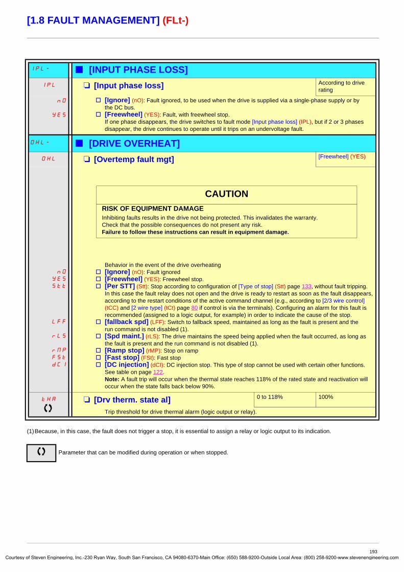
Courtes
[1.8 FAULT MANAGEMENT] (FLt-)
(1)Because, in this case, the fault does not trigger a stop, it is essential to assign a relay or logic output to its indication.
IPL- b [INPUT PHASE LOSS]IPL� M [Input phase loss] According to drive
rating
nO
YES
v [Ignore] (nO): Fault ignored, to be used when the drive is supplied via a single-phase supply or by the DC bus.
v [Freewheel] (YES): Fault, with freewheel stop. If one phase disappears, the drive switches to fault mode [Input phase loss] (IPL), but if 2 or 3 phases disappear, the drive continues to operate until it trips on an undervoltage fault.
OHL- b [DRIVE OVERHEAT]OHL M [Overtemp fault mgt] [Freewheel] (YES)
nO
YES
Stt
LFF
rLS
rMP
FSt
dCI
Behavior in the event of the drive overheatingv [Ignore] (nO): Fault ignoredv [Freewheel] (YES): Freewheel stop.v [Per STT] (Stt): Stop according to configuration of [Type of stop] (Stt) page 133, without fault tripping.
In this case the fault relay does not open and the drive is ready to restart as soon as the fault disappears, according to the restart conditions of the active command channel (e.g., according to [2/3 wire control] (tCC) and [2 wire type] (tCt) page 80 if control is via the terminals). Configuring an alarm for this fault is recommended (assigned to a logic output, for example) in order to indicate the cause of the stop.
v [fallback spd] (LFF): Switch to fallback speed, maintained as long as the fault is present and the run command is not disabled (1).
v [Spd maint.] (rLS): The drive maintains the speed being applied when the fault occurred, as long as the fault is present and the run command is not disabled (1).
v [Ramp stop] (rMP): Stop on rampv [Fast stop] (FSt): Fast stopv [DC injection] (dCI): DC injection stop. This type of stop cannot be used with certain other functions.
See table on page 122.Note: A fault trip will occur when the thermal state reaches 118% of the rated state and reactivation will occur when the state falls back below 90%.
tHA M [Drv therm. state al] 0 to 118% 100%
Trip threshold for drive thermal alarm (logic output or relay).
Parameter that can be modified during operation or when stopped.
CAUTIONRISK OF EQUIPMENT DAMAGEInhibiting faults results in the drive not being protected. This invalidates the warranty.Check that the possible consequences do not present any risk.Failure to follow these instructions can result in equipment damage.
193y of Steven Engineering, Inc.-230 Ryan Way, South San Francisco, CA 94080-6370-Main Office: (650) 588-9200-Outside Local Area: (800) 258-9200-www.stevenengineering.com

Courtes
[1.8 FAULT MANAGEMENT] (FLt-)
Deferred stop on thermal alarmThis function can be used in intermittent applications, where it is desirable to avoid any stops for which no command has been given. It prevents untimely stopping if the drive or motor overheats, by authorizing operation until the next stop for which a command is given. At the next stop, the drive is locked until the thermal state falls back to a value which undershoots the set threshold by 20%. Example: A trip threshold set at 80% enables reactivation at 60%.One thermal state threshold must be defined for the drive, and one thermal state threshold for the motor(s), which will trip the deferred stop.
Code Name/Description Adjustment range Factory setting
SAt- b [THERMAL ALARM STOP]SAt M [Thermal alarm stop] [No] (nO)
nO
YES
v [No] (nO): Function inactive (in this case, the following parameters cannot be accessed)v [Yes] (YES): Freewheel stop on drive or motor thermal alarm
tHA M [Drv therm. state al] 0 to 118% 100%
Thermal state threshold of the drive tripping the deferred stop.
ttd M [Motor therm. level] 0 to 118% 100%
Thermal state threshold of the motor tripping the deferred stop.
ttd2 M [Motor2 therm. level] 0 to 118% 100%
Thermal state threshold of the motor 2 tripping the deferred stop.
ttd3 M [Motor3 therm. level] 0 to 118% 100%
Thermal state threshold of the motor 3 tripping the deferred stop.
Parameter that can be modified during operation or when stopped.
CAUTIONThe drive and motor are no longer protected in the event of thermal alarm stops. This invalidates the warranty.Check that the possible consequences do not present any risk.Failure to follow these instructions can result in equipment damage.
194y of Steven Engineering, Inc.-230 Ryan Way, South San Francisco, CA 94080-6370-Main Office: (650) 588-9200-Outside Local Area: (800) 258-9200-www.stevenengineering.com

Courtes
[1.8 FAULT MANAGEMENT] (FLt-)
(1)Because, in this case, the fault does not trigger a stop, it is essential to assign a relay or logic output to its indication.
Code Name/Description Adjustment range Factory setting
EtF- b [EXTERNAL FAULT]EtF M [External fault ass.] [No] (nO)
nO
LI1
-
-
-
v [No] (nO): Function inactivev [LI1] (LI1)
: :
v [...] (...): See the assignment conditions on page 116.If the assigned bit is at 0, there is no external fault.If the assigned bit is at 1, there is an external fault.Logic can be configured via [External fault config] (LEt) if a logic input has been assigned.
LEt M [External fault config] [Active high] (HIG)
LO
HIG
Parameter can be accessed if the external fault has been assigned to a logic input. It defines the positive or negative logic of the input assigned to the fault.
v [Active low] (LO): Fault on falling edge (change from 1 to 0) of the assigned inputv [Active high] (HIG): Fault on rising edge (change from 0 to 1) of the assigned input
EPL M [External fault mgt] [Freewheel] (YES)
nO
YES
Stt
LFF
rLS
rMP
FSt
dCI
Type of stop in the event of an external faultv [Ignore] (nO): Fault ignoredv [Freewheel] (YES): Freewheel stop.v [Per STT] (Stt): Stop according to configuration of [Type of stop] (Stt) page 133, without fault tripping.
In this case the fault relay does not open and the drive is ready to restart as soon as the fault disappears, according to the restart conditions of the active command channel (e.g., according to [2/3 wire control] (tCC) and [2 wire type] (tCt) page 80 if control is via the terminals). Configuring an alarm for this fault is recommended (assigned to a logic output, for example) in order to indicate the cause of the stop.
v [fallback spd] (LFF): Switch to fallback speed, maintained as long as the fault is present and the run command is not disabled (1).
v [Spd maint.] (rLS): The drive maintains the speed being applied when the fault occurred, as long as the fault is present and the run command is not disabled (1).
v [Ramp stop] (rMP): Stop on rampv [Fast stop] (FSt): Fast stopv [DC injection] (dCI): DC injection stop. This type of stop cannot be used with certain other functions.
See table on page 122.
195y of Steven Engineering, Inc.-230 Ryan Way, South San Francisco, CA 94080-6370-Main Office: (650) 588-9200-Outside Local Area: (800) 258-9200-www.stevenengineering.com

Courtes
[1.8 FAULT MANAGEMENT] (FLt-)
Code Name/Description Adjustment range Factory setting
USb- b [UNDERVOLTAGE MGT]USb M [UnderV. fault mgt] [Flt&R1open] (0)
0
1
2
Behavior of the drive in the event of an undervoltagev [Flt&R1open] (0): Fault and fault relay open.v [Flt&R1close] (1): Fault and fault relay closed.v [Alarm] (2): Alarm and fault relay remains closed. The alarm may be assigned to a logic output or a relay.
UrES
200
220
240
260
380
400
440
460
480
500
600
690
M [Mains voltage] According to drive voltage rating
According to drive voltage rating
Rated voltage of the line supply in V.For ATV61pppM3:
v [200V ac] (200): 200 Volts ACv [220V ac] (220): 220 Volts ACv [240V ac] (240): 240 Volts ACv [260V ac] (260): 260 Volts AC (factory setting)
For ATV61pppN4:v [380V ac] (380): 380 Volts ACv [400V ac] (400): 400 Volts ACv [440V ac] (440): 440 Volts ACv [460V ac] (460): 460 Volts ACv [480V ac] (480): 480 Volts AC (factory setting)
For ATV61pppY:v [500 Vac] (500): 500 Volts ACv [600 Vac] (600): 600 Volts ACv [690 Vac] (690): 690 Volts AC (factory setting)
USL M [Undervoltage level]Undervoltage fault trip level setting in V. The adjustment range and factory setting are determined by the drive voltage rating and the [Mains voltage] (UrES) value.
USt M [Undervolt. time out] 0.2 s to 999.9 s 0.2 s
Time delay for taking undervoltage fault into account
StP M [UnderV. prevention] [No] (nO)
nO
MMS
rMP
LnF
Behavior in the event of the undervoltage fault prevention level being reachedv [No] (nO): No actionv [DC Maintain] (MMS): This stop mode uses the inertia to maintain the DC bus voltage as long
as possible.v [Ramp stop] (rMP): Stop following an adjustable ramp [Max stop time] (StM).v [Lock-out] (LnF): Lock (freewheel stop) without fault
Parameter that can be modified during operation or when stopped.
196y of Steven Engineering, Inc.-230 Ryan Way, South San Francisco, CA 94080-6370-Main Office: (650) 588-9200-Outside Local Area: (800) 258-9200-www.stevenengineering.com

Courtes
[1.8 FAULT MANAGEMENT] (FLt-)
Code Name/Description Adjustment range Factory setting
USb- b [UNDERVOLTAGE MGT]tSM M [UnderV. restart tm] 1.0 s to 999.9 s 1.0 s
Time delay before authorizing the restart after a complete stop for [UnderV. prevention] (StP) = [Ramp stop] (rMP), if the voltage has returned to normal.
UPL M [Prevention level]Undervoltage fault prevention level setting in V, which can be accessed if [UnderV. prevention] (StP) is not [No] (nO). The adjustment range and factory setting are determined by the drive voltage rating and the [Mains voltage] (UrES) value.
StM M [Max stop time] 0.01 to 60.00 s 1.00 s
Ramp time if [UnderV. prevention] (StP) = [Ramp stop] (rMP).
tbS M [DC bus maintain tm] 1 to 9,999 s 9,999 s
DC bus maintain time if [UnderV. prevention] (StP) = [DC Maintain] (MMS).
tIt- b [IGBT TESTS]Strt M [IGBT test] [No] (nO)
nO
YES
v [No] (nO): No testv [Yes] (YES): The IGBTs are tested on power up and every time a run command is sent. These tests cause
a slight delay (a few ms). In the event of a fault, the drive will lock. The following faults can be detected:- Drive output short-circuit (terminals U-V-W): SCF display- IGBT faulty: xtF, where x indicates the number of the IGBT concerned- IGBT short-circuited: x2F, where x indicates the number of the IGBT concerned
Parameter that can be modified during operation or when stopped.
197y of Steven Engineering, Inc.-230 Ryan Way, South San Francisco, CA 94080-6370-Main Office: (650) 588-9200-Outside Local Area: (800) 258-9200-www.stevenengineering.com

Courtes
[1.8 FAULT MANAGEMENT] (FLt-)
(1)Because, in this case, the fault does not trigger a stop, it is essential to assign a relay or logic output to its indication.
Code Name/Description Adjustment range Factory setting
LFL- b [4-20mA LOSS]LFL2 M [AI2 4-20mA loss] [Ignore] (nO)
nO
YES
Stt
LFF
rLS
rMP
FSt
dCI
v [Ignore] (nO): Fault ignored. This configuration is the only one possible if [AI2 min. value] (CrL2) page 86 is not greater than 3 mA or if [AI2 Type] (AI2t) page 86 = [Voltage] (10U).
v [Freewheel] (YES): Freewheel stop.v [Per STT] (Stt): Stop according to configuration of [Type of stop] (Stt) page 133, without fault tripping.
In this case the fault relay does not open and the drive is ready to restart as soon as the fault disappears, according to the restart conditions of the active command channel (e.g., according to [2/3 wire control] (tCC) and [2 wire type] (tCt) page 80 if control is via the terminals). Configuring an alarm for this fault is recommended (assigned to a logic output, for example) in order to indicate the cause of the stop.
v [fallback spd] (LFF): Switch to fallback speed, maintained as long as the fault is present and the run command is not disabled (1).
v [Spd maint.] (rLS): The drive maintains the speed being applied when the fault occurred, as long as the fault is present and the run command is not disabled (1).
v [Ramp stop] (rMP): Stop on rampv [Fast stop] (FSt): Fast stopv [DC injection] (dCI): DC injection stop. This type of stop cannot be used with certain other functions.
See table on page 122.
LFL3 M [AI3 4-20mA loss] Can be accessed if a VW3A3202 option card has been inserted. [Ignore] (nO)
nO
YES
Stt
LFF
rLS
rMP
FSt
dCI
v [Ignore] (nO): Fault ignored. This configuration is the only one possible if [AI3 min. value] (CrL3) page 87 is not greater than 3 mA.
v [Freewheel] (YES): Freewheel stop.v [Per STT] (Stt): Stop according to configuration of [Type of stop] (Stt) page 133, without fault tripping.
In this case the fault relay does not open and the drive is ready to restart as soon as the fault disappears, according to the restart conditions of the active command channel (e.g., according to [2/3 wire control] (tCC) and [2 wire type] (tCt) page 80 if control is via the terminals). Configuring an alarm for this fault is recommended (assigned to a logic output, for example) in order to indicate the cause of the stop.
v [fallback spd] (LFF): Switch to fallback speed, maintained as long as the fault is present and the run command is not disabled (1).
v [Spd maint.] (rLS): The drive maintains the speed being applied when the fault occurred, as long as the fault is present and the run command is not disabled (1).
v [Ramp stop] (rMP): Stop on rampv [Fast stop] (FSt): Fast stopv [DC injection] (dCI): DC injection stop. This type of stop cannot be used with certain other functions.
See table on page 122.
LFL4 M [AI4 4-20mA loss] Can be accessed if a VW3A3202 option card has been inserted. [Ignore] (nO)
nO
YES
Stt
LFF
rLS
rMP
FSt
dCI
v [Ignore] (nO): Fault ignored. This configuration is the only one possible if [AI4 min. value] (CrL4) page 88 is not greater than 3 mA or if [AI4 Type] (AI4t) page 88 = [Voltage] (10U).
v [Freewheel] (YES): Freewheel stop.v [Per STT] (Stt): Stop according to configuration of [Type of stop] (Stt) page 133, without fault tripping.
In this case the fault relay does not open and the drive is ready to restart as soon as the fault disappears, according to the restart conditions of the active command channel (e.g., according to [2/3 wire control] (tCC) and [2 wire type] (tCt) page 80 if control is via the terminals). Configuring an alarm for this fault is recommended (assigned to a logic output, for example) in order to indicate the cause of the stop.
v [fallback spd] (LFF): Switch to fallback speed, maintained as long as the fault is present and the run command is not disabled (1).
v [Spd maint.] (rLS): The drive maintains the speed being applied when the fault occurred, as long as the fault is present and the run command is not disabled (1).
v [Ramp stop] (rMP): Stop on rampv [Fast stop] (FSt): Fast stopv [DC injection] (dCI): DC injection stop. This type of stop cannot be used with certain other functions.
See table on page 122.
198y of Steven Engineering, Inc.-230 Ryan Way, South San Francisco, CA 94080-6370-Main Office: (650) 588-9200-Outside Local Area: (800) 258-9200-www.stevenengineering.com

Courtes
[1.8 FAULT MANAGEMENT] (FLt-)
Parameter can be accessed in [Expert] mode.
Code Name/Description Adjustment range Factory setting
InH- b [FAULT INHIBITION]InH M [Fault inhibit assign.] [No] (nO)
nO
LI1
-
-
-
To assign fault inhibit, press the “ENT” key for 2 s.
v [No] (nO): Function inactive, thereby preventing access to other function parameters.v [LI1] (LI1)
: :
v [...] (...): See the assignment conditions on page 116.If the assigned input or bit is at 0, fault monitoring is active. If the assigned input or bit is at 1, fault monitoring is inactive. Active faults are reset on a rising edge (change from 0 to 1) of the assigned input or bit.
Note: The “Power Removal” function and any faults that prevent any form of operation are not affected by this function. A list of faults affected by this function appears on pages 238 to 243.
InHS
nO
Frd
rrS
M [Forced Run] [No] (nO)
This parameter causes the run command to be forced in a specific direction when the input or bit for fault inhibition is at 1, with priority over all other commands with the exception of “Power Removal”. To assign forced run, press and hold down the “ENT” key for 2 s.
v [No] (nO): Function inactivev [Fw.For.Run] (Frd): Forced forward run.v [Rev.For.Run] (rrS): Forced reverse run.
InHr M [Forced Run Ref.] 0 to 500 or 1,000 Hz according to rating
50 Hz
The parameter can be accessed if [Forced Run] (InHS) is not [No] (nO)This parameter causes the reference to be forced to the configured value when the input or bit for fault inhibition is at 1, with priority over all other references. Value 0 = function inactive. The factory setting changes to 60 Hz if [Standard mot. freq] (bFr) = [60 Hz NEMA] (60).
CAUTIONInhibiting faults results in the drive not being protected. This invalidates the warranty.Check that the possible consequences do not present any risk.Failure to follow these instructions can result in equipment damage.
DANGERUNINTENDED EQUIPMENT OPERATION
• Check that it is safe to force the run command.
Failure to follow these instructions will result in death or serious injury.
199y of Steven Engineering, Inc.-230 Ryan Way, South San Francisco, CA 94080-6370-Main Office: (650) 588-9200-Outside Local Area: (800) 258-9200-www.stevenengineering.com

Courtes
[1.8 FAULT MANAGEMENT] (FLt-)
(1)Because, in this case, the fault does not trigger a stop, it is essential to assign a relay or logic output to its indication.
Code Name/Description Adjustment range Factory setting
CLL- b [COM. FAULT MANAGEMENT]CLL M [Network fault mgt] [Freewheel] (YES)
nO
YES
Stt
LFF
rLS
rMP
FSt
dCI
Behavior of the drive in the event of a communication fault with a communication cardv [Ignore] (nO): Fault ignoredv [Freewheel] (YES): Freewheel stop.v [Per STT] (Stt): Stop according to configuration of [Type of stop] (Stt) page 133, without fault tripping.
In this case the fault relay does not open and the drive is ready to restart as soon as the fault disappears, according to the restart conditions of the active command channel (e.g., according to [2/3 wire control] (tCC) and [2 wire type] (tCt) page 80 if control is via the terminals). Configuring an alarm for this fault is recommended (assigned to a logic output, for example) in order to indicate the cause of the stop.
v [fallback spd] (LFF): Switch to fallback speed, maintained as long as the fault is present and the run command is not disabled (1).
v [Spd maint.] (rLS): The drive maintains the speed being applied when the fault occurred, as long as the fault is present and the run command is not disabled (1).
v [Ramp stop] (rMP): Stop on rampv [Fast stop] (FSt): Fast stopv [DC injection] (dCI): DC injection stop. This type of stop cannot be used with certain other functions.
See table on page 122.
COL M [CANopen fault mgt] [Freewheel] (YES)
nO
YES
Stt
LFF
rLS
rMP
FSt
dCI
Behavior of the drive in the event of a communication fault with integrated CANopenv [Ignore] (nO): Fault ignoredv [Freewheel] (YES): Freewheel stop.v [Per STT] (Stt): Stop according to configuration of [Type of stop] (Stt) page 133, without fault tripping.
In this case the fault relay does not open and the drive is ready to restart as soon as the fault disappears, according to the restart conditions of the active command channel (e.g., according to [2/3 wire control] (tCC) and [2 wire type] (tCt) page 80 if control is via the terminals). Configuring an alarm for this fault is recommended (assigned to a logic output, for example) in order to indicate the cause of the stop.
v [fallback spd] (LFF): Switch to fallback speed, maintained as long as the fault is present and the run command is not disabled (1).
v [Spd maint.] (rLS): The drive maintains the speed being applied when the fault occurred, as long as the fault is present and the run command is not disabled (1).
v [Ramp stop] (rMP): Stop on rampv [Fast stop] (FSt): Fast stopv [DC injection] (dCI): DC injection stop. This type of stop cannot be used with certain other functions.
See table on page 122.
SLL M [Modbus fault mgt] [Freewheel] (YES)
nO
YES
Stt
LFF
rLS
rMP
FSt
dCI
Behavior of the drive in the event of a communication fault with integrated Modbusv [Ignore] (nO): Fault ignoredv [Freewheel] (YES): Freewheel stop.v [Per STT] (Stt): Stop according to configuration of [Type of stop] (Stt) page 133, without fault tripping.
In this case the fault relay does not open and the drive is ready to restart as soon as the fault disappears, according to the restart conditions of the active command channel (e.g., according to [2/3 wire control] (tCC) and [2 wire type] (tCt) page 80 if control is via the terminals). Configuring an alarm for this fault is recommended (assigned to a logic output, for example) in order to indicate the cause of the stop.
v [fallback spd] (LFF): Switch to fallback speed, maintained as long as the fault is present and the run command is not disabled (1).
v [Spd maint.] (rLS): The drive maintains the speed being applied when the fault occurred, as long as the fault is present and the run command is not disabled (1).
v [Ramp stop] (rMP): Stop on rampv [Fast stop] (FSt): Fast stopv [DC injection] (dCI): DC injection stop. This type of stop cannot be used with certain other functions.
See table on page 122.
200y of Steven Engineering, Inc.-230 Ryan Way, South San Francisco, CA 94080-6370-Main Office: (650) 588-9200-Outside Local Area: (800) 258-9200-www.stevenengineering.com

Courtes
[1.8 FAULT MANAGEMENT] (FLt-)
(1)Because, in this case, the fault does not trigger a stop, it is essential to assign a relay or logic output to its indication.
Code Name/Description Adjustment range Factory setting
tId- b [TORQUE OR I LIM. DETECT.]SSb M [Trq/I limit. Stop] [Ignore] (nO)
nO
YES
Stt
LFF
rLS
rMP
FSt
dCI
Behavior in the event of switching to torque or current limitationv [Ignore] (nO): Fault ignoredv [Freewheel] (YES): Freewheel stop.v [Per STT] (Stt): Stop according to configuration of [Type of stop] (Stt) page 133, without fault tripping.
In this case the fault relay does not open and the drive is ready to restart as soon as the fault disappears, according to the restart conditions of the active command channel (e.g., according to [2/3 wire control] (tCC) and [2 wire type] (tCt) page 80 if control is via the terminals). Configuring an alarm for this fault is recommended (assigned to a logic output, for example) in order to indicate the cause of the stop.
v [fallback spd] (LFF): Switch to fallback speed, maintained as long as the fault is present and the run command is not disabled (1).
v [Spd maint.] (rLS): The drive maintains the speed being applied when the fault occurred, as long as the fault is present and the run command is not disabled (1).
v [Ramp stop] (rMP): Stop on rampv [Fast stop] (FSt): Fast stopv [DC injection] (dCI): DC injection stop. This type of stop cannot be used with certain other functions.
See table on page 122.
StO M [Trq/I limit. time out] 0 to 9,999 ms 1,000 ms
(If fault has been configured)Time delay for taking SSF “Limitation” fault into account
Parameter that can be modified during operation or when stopped.
201y of Steven Engineering, Inc.-230 Ryan Way, South San Francisco, CA 94080-6370-Main Office: (650) 588-9200-Outside Local Area: (800) 258-9200-www.stevenengineering.com

Courtes
[1.8 FAULT MANAGEMENT] (FLt-)
Use of the "Pulse input" to measure the speed of rotation of the motorThis function uses the "Pulse input" from the VW3A3202 extension card and can, therefore, only be used if this card has been inserted and if the "Pulse input" is not being used for another function.
Example of useA notched disc driven by the motor and connected to a proximity sensor can be used to generate a frequency signal that is proportional to the speed of rotation of the motor.
When applied to the "Pulse input", this signal supports:• Measurement and display of the motor speed: signal frequency = 1/T. This frequency is displayed by means of the [Pulse in. work.
freq.] (FqS) parameter, page 44 or 46.• Overspeed detection (if the measured speed exceeds a preset threshold, the drive will trip on a fault).• Detection of a speed threshold that can be adjusted using [Pulse warning thd.] (FqL) page 59 and is assignable to a relay or logic
output, see page 94.
T
Time, in seconds
202y of Steven Engineering, Inc.-230 Ryan Way, South San Francisco, CA 94080-6370-Main Office: (650) 588-9200-Outside Local Area: (800) 258-9200-www.stevenengineering.com

Courtes
[1.8 FAULT MANAGEMENT] (FLt-)
Code Name/Description Adjustment range Factory setting
FqF- b [FREQUENCY METER]Can be accessed if a VW3A3202 option card has been inserted
FqF M [Frequency meter] [No] (nO)
nO
YES
Activation of the speed measurement function. v [No] (nO): Function inactivev [Yes] (YES): Function active, assignment only possible if no other functions have been assigned to the
"Pulse input".
FqC M [Pulse scal. divisor] 1.0 to 100.0 1.0
Scaling factor for the "Pulse input" (divisor). The frequency measured is displayed by means of the [Pulse in. work. freq.] (FqS) parameter, page 44 or 46.
FqA
nO
-
M [Overspd. pulse thd.] [No] (nO)
Activation and adjustment of overspeed monitoring: [Overspeed] (SOF) fault.v [No] (nO): No overspeed monitoringv 1 Hz to 30.00 Hz: Adjustment of the frequency tripping threshold on the "Pulse input" divided by [Pulse
scal. divisor] (FqC)
tdS M [Pulse overspd delay] 0.0 s to 10.0 s 0.0 s
Time delay for taking overspeed fault into account
Fdt M [Level fr. pulse ctrl] [No] (nO)
nO
-
Activation and adjustment of monitoring for the Pulse input (speed feedback): [Speed fdback loss] (SPF) fault
v [No] (nO): No monitoring of speed feedbackv 0.1 Hz to 500.0 Hz: Adjustment of the motor frequency threshold for tripping a speed feedback fault
(difference between the estimated frequency and the measured speed)
203y of Steven Engineering, Inc.-230 Ryan Way, South San Francisco, CA 94080-6370-Main Office: (650) 588-9200-Outside Local Area: (800) 258-9200-www.stevenengineering.com

Courtes
[1.8 FAULT MANAGEMENT] (FLt-)
Code Name/Description Adjustment range Factory setting
brP- b [DB RES. PROTECTION]brO M [DB res. protection] [No] (nO)
nO
YES
FLt
v [No] (nO): No braking resistor protection (thereby preventing access to the other function parameters).v [Alarm] (YES): Alarm. The alarm may be assigned to a logic output or a relay (see page 94).v [Fault] (FLt) : Switch to fault (bOF) with locking of drive (freewheel stop).
Note: The thermal state of the resistor can be displayed on the graphic display terminal. It is calculated for as long as the drive control remains connected to the power supply.
brP M [DB Resistor Power] 0.1 kW (0.13 HP) to 1,000 kW (1,333 HP)
0.1 kW (0.13 HP)
The parameter can be accessed if [DB res. protection] (brO) is not [No] (nO).Rated power of the resistor used.
brU M [DB Resistor value] 0.1 to 200 Ohms 0.1 Ohm
The parameter can be accessed if [DB res. protection] (brO) is not [No] (nO).Rated value of the braking resistor in Ohms.
bUF- b [BU PROTECTION]Parameter accessible at and above ATV61HD55M3X, ATV61HD90N4 and ATV61HC11Y.
bUb M [Brake res. fault Mgt] [Freewheel] (YES)
nO
YES
Management of short-circuit [DB unit sh. circuit] (bUF) and overheating [Internal- th. sensor] (InFb) faults in the braking unit.
v [Ignore] (nO): Fault ignored. Configuration to be used if there is no braking unit or resistor connected to the drive.
v [Freewheel] (YES): Freewheel stop
tnF- b [AUTO TUNING FAULT]tnL M [Autotune fault mgt] [Freewheel] (YES)
nO
YES
v [Ignore] (nO): Fault ignored. v [Freewheel] (YES): Freewheel stop.
Parameter that can be modified during operation or when stopped.
204y of Steven Engineering, Inc.-230 Ryan Way, South San Francisco, CA 94080-6370-Main Office: (650) 588-9200-Outside Local Area: (800) 258-9200-www.stevenengineering.com

Courtes
[1.8 FAULT MANAGEMENT] (FLt-)
Card pairingFunction can only be accessed in [Expert] mode.This function is used to detect whenever a card has been replaced or the software has been modified in any way.When a pairing password is entered, the parameters of the cards currently inserted are stored. On every subsequent power-up these parameters are verified and in the event of a discrepancy the drive locks in HCF fault mode. Before the drive can be restarted you must revert to the original situation or re-enter the pairing password.
The following parameters are verified:• The type of card for: all cards• The software version for: the two control cards, the VW3A3202 extension card, the Controller Inside card and the communication
cards• The serial number for: both control cards
Code Name/Description Adjustment range Factory setting
PPI- b [CARDS PAIRING]PPI M [Pairing password] OFF to 9,999 [OFF] (OFF)
The [OFF] (OFF) value signifies that the card pairing function is inactive.The [ON] (On) value signifies that card pairing is active and that an access code must be entered in order to start the drive in the event of a card pairing fault. As soon as the code has been entered the drive is unlocked and the code changes to [ON] (On).
- The PPI code is an unlock code known only to Schneider Electric Product Support.
205y of Steven Engineering, Inc.-230 Ryan Way, South San Francisco, CA 94080-6370-Main Office: (650) 588-9200-Outside Local Area: (800) 258-9200-www.stevenengineering.com

Courtes
[1.8 FAULT MANAGEMENT] (FLt-)
Process underload faultA process underload is detected when the next event occurs and remains pending for a minimum time (ULt), which is configurable:
• The motor is in steady state and the torque is below the set underload limit (LUL, LUn, rMUd parameters).
The motor is in steady state when the offset between the frequency reference and motor frequency falls below the configurable threshold (Srb).
.
Between zero frequency and the rated frequency, the curve reflects the following equation:
torque = LUL +
The underload function is not active for frequencies below rMUd.
A relay or a logic output can be assigned to the signaling of this fault in the [1.5 INPUTS / OUTPUTS CFG] (I-O-) menu.
0
LUL
LUn
rMUd FrSFrequency
Torque as a % of the rated torque
Underload zone
(LUn - LUL) x (frequency)2(rated frequency)2
206y of Steven Engineering, Inc.-230 Ryan Way, South San Francisco, CA 94080-6370-Main Office: (650) 588-9200-Outside Local Area: (800) 258-9200-www.stevenengineering.com

Courtes
[1.8 FAULT MANAGEMENT] (FLt-)
(1)The parameter can also be accessed in the [1.3 SETTINGS] (SEt-) menu.
Code Name/Description Adjustment range Factory setting
ULd- b [PROCESS UNDERLOAD] ULt M [Unld T. Del. Detect] 0 to 100 s 0 s
Underload detection time delay. A value of 0 deactivates the function and renders the other parameters inaccessible.
LUn M [Unld.Thr.Nom.Speed] (1) 20 to 100% 60%
Underload threshold at rated motor frequency ([Rated motor freq.] (FrS) page 35), as a % of the rated motor torque.
LUL M [Unld.Thr.0.Speed] (1) 0 to [Unld.Thr.Nom.Speed] (LUn)
0%
Underload threshold at zero frequency, as a % of the rated motor torque.
rMUd M [Unld. Freq.Thr. Det.] (1) 0 to 500 or 1,000 Hz according to rating
0 Hz
Minimum frequency underload detection threshold
Srb M [Hysteresis Freq.Att.] (1) 0.3 to 500 or 1,000 Hz according to rating
0.3 Hz
Maximum deviation between the frequency reference and the motor frequency, which defines steady state operation.
UdL M [Underload Mangmt.] [Freewheel] (YES)
nO
YES
rMP
FSt
Behavior on switching to underload detection.v [Ignore] (nO): Fault ignoredv [Freewheel] (YES): Freewheel stopv [Ramp stop] (rMP): Stop on rampv [Fast stop] (FSt): Fast stop
FtU M [Underload T.B.Rest.] (1) 0 to 6 min 0 min
This parameter cannot be accessed if [Underload Mangmt.] (UdL) = [Ignore] (nO).Minimum time permitted between an underload being detected and any automatic restart.In order for an automatic restart to be possible, the value of [Max. restart time] (tAr) page 189 must exceed that of this parameter by at least one minute.
Parameter that can be modified during operation or when stopped.
207y of Steven Engineering, Inc.-230 Ryan Way, South San Francisco, CA 94080-6370-Main Office: (650) 588-9200-Outside Local Area: (800) 258-9200-www.stevenengineering.com

Courtes
[1.8 FAULT MANAGEMENT] (FLt-)
Process overload faultA process overload is detected when the next event occurs and remains pending for a minimum time (tOL), which is configurable:
• The drive is in current limitation mode.• The motor is in steady state and the current is above the set overload threshold (LOC).
The motor is in steady state when the offset between the frequency reference and motor frequency falls below the configurable threshold (Srb).A relay or a logic output can be assigned to the signaling of this fault in the [1.5 INPUTS / OUTPUTS CFG] (I-O-) menu.
(1)The parameter can also be accessed in the [1.3 SETTINGS] (SEt-) menu.
Code Name/Description Adjustment range Factory setting
OLd- b [PROCESS OVERLOAD] tOL M [Unld Time Detect.] 0 to 100 s 0 s
Overload detection time delay. A value of 0 deactivates the function and renders the other parameters inaccessible.
LOC M [Ovld Detection Thr.] (1) 70 to 150% 110%
Overload detection threshold, as a % of the rated motor current [Rated mot. current] (nCr). This value must be less than the limit current in order for the function to work.
Srb M [Hysteresis Freq.Att.] (1) 0.3 to 500 or 1,000 Hz according to rating
0.3 Hz
Maximum deviation between the frequency reference and the motor frequency, which defines steady state operation.
OdL M [Ovld.Proces.Mngmt] [Freewheel] (YES)
nO
YES
rMP
FSt
Behavior on switching to overload detection.v [Ignore] (nO): Fault ignoredv [Freewheel] (YES): Freewheel stopv [Ramp stop] (rMP): Stop on rampv [Fast stop] (FSt): Fast stop
FtO M [Overload T.B.Rest.] (1) 0 to 6 min 0 min
This parameter cannot be accessed if [Ovld.Proces.Mngmt] (OdL) = [Ignore] (nO).Minimum time permitted between an overload being detected and any automatic restart.In order for an automatic restart to be possible, the value of [Max. restart time] (tAr) page 189 must exceed that of this parameter by at least one minute.
Parameter that can be modified during operation or when stopped.
208y of Steven Engineering, Inc.-230 Ryan Way, South San Francisco, CA 94080-6370-Main Office: (650) 588-9200-Outside Local Area: (800) 258-9200-www.stevenengineering.com

Courtes
[1.8 FAULT MANAGEMENT] (FLt-)
(1)Because, in this case, the fault does not trigger a stop, it is essential to assign a relay or logic output to its indication.
Code Name/Description Adjustment range Factory setting
FdL- b [DAMPER FAULT MGT.]FdL M [Damper fault mgt.] [Freewheel] (YES)
nO
YES
Stt
LFF
rLS
rMP
FSt
dCI
Type of stop in the event of a damper fault: [Damper stuck] (Fd1)v [Ignore] (nO): Fault ignoredv [Freewheel] (YES): Freewheel stopv [Per STT] (Stt): Stop according to configuration of [Type of stop] (Stt) page 133, without fault tripping. In
this case the fault relay does not open and the drive is ready to restart as soon as the fault disappears, according to the restart conditions of the active command channel (e.g. according to [2/3 wire control] (tCC) and [2 wire type] (tCt) page 80 if control is via the terminals). It is advisable to configure an alarm for this fault (assigned to a logic output, for example) in order to indicate the cause of the stop.
v [fallback spd] (LFF): Change to fallback speed, maintained as long as the fault persists and the run command has not been removed (1).
v [Spd maint.] (rLS): The drive maintains the speed being applied when the fault occurred, as long as the fault is present and the run command has not been removed (1).
v [Ramp stop] (rMP): Stop on rampv [Fast stop] (FSt): Fast stopv [DC injection] (dCI): DC injection stop. This type of stop cannot be used with certain other functions. See
table on page 122.
209y of Steven Engineering, Inc.-230 Ryan Way, South San Francisco, CA 94080-6370-Main Office: (650) 588-9200-Outside Local Area: (800) 258-9200-www.stevenengineering.com

Courtes
[1.8 FAULT MANAGEMENT] (FLt-)
(1)The parameter can also be accessed in the [1.3 SETTINGS] (SEt-) and [1.7 APPLICATION FUNCT.] (FUn-) menus.(2) In corresponds to the rated drive current indicated in the Installation Manual and on the drive nameplate.(3)Warning: These settings are independent of the [AUTO DC INJECTION] (AdC-) function.
Code Name/Description Adjustment range Factory setting
LFF- b [FALLBACK SPEED]LFF M [Fallback speed] 0 to 500 or 1,000 Hz
according to rating0 Hz
Selection of the fallback speed
FSt- b [RAMP DIVIDER]dCF M [Ramp divider] (1) 0 to 10 4
The ramp that is enabled (dEC or dE2) is then divided by this coefficient when stop requests are sent.Value 0 corresponds to a minimum ramp time.
dCI- b [DC INJECTION]IdC M [DC inject. level 1] (1) (3) 0.1 to 1.1 or 1.2 In (2)
according to rating0.64 In (2)
Level of DC injection braking current activated via logic input or selected as stop mode.
tdI M [DC injection time 1] (1) (3) 0.1 to 30 s 0.5 s
Maximum current injection time [DC inject. level 1] (IdC). After this time the injection current becomes [DC inject. level 2] (IdC2).
IdC2 M [DC inject. level 2] (1) (3) 0.1 In (2) to [DC inject. level 1] (IdC)
0.5 In (2)
Injection current activated by logic input or selected as stop mode, once period of time [DC injection time 1] (tdI) has elapsed.
tdC M [DC injection time 2] (1) (3) 0.1 to 30 s 0.5 s
Maximum injection time [DC inject. level 2] (IdC2) for injection, selected as stop mode only. (Can be accessed if [Type of stop] (Stt) = [DC injection] (dCI)).
Parameter that can be modified during operation or when stopped.
CAUTIONCheck that the motor will withstand this current without overheating.Failure to follow these instructions can result in equipment damage.
CAUTIONCheck that the motor will withstand this current without overheating.Failure to follow these instructions can result in equipment damage.
210y of Steven Engineering, Inc.-230 Ryan Way, South San Francisco, CA 94080-6370-Main Office: (650) 588-9200-Outside Local Area: (800) 258-9200-www.stevenengineering.com

Courtes
[1.9 COMMUNICATION] (COM-)
With graphic display terminal:
With integrated display terminal:
RDY Term +0.00 Hz REMMAIN MENU
1 DRIVE MENU2 ACCESS LEVEL3 OPEN / SAVE AS4 PASSWORD5 LANGUAGE
Code T/K
ENT
RDY Term +0.00 Hz REM1 DRIVE MENU
1.1 SIMPLY START1.2 MONITORING1.3 SETTINGS1.4 MOTOR CONTROL1.5 INPUTS / OUTPUTS CFG
Code << >> T/K1.6 COMMAND1.7 APPLICATION FUNCT.1.8 FAULT MANAGEMENT1.9 COMMUNICATION1.10 DIAGNOSTICS1.11 IDENTIFICATION1.12 FACTORY SETTINGS1.13 USER MENU1.14 PROGRAMMABLE CARD
ENTRUN Term +0.00 Hz REM
1.9 COMMUNICATIONCOM. SCANNER INPUTCOM. SCANNER OUTPUTMODBUS HMIMODBUS NETWORKCANopen
Code << >> T/K
XXX
SIM-
ESC
ESC
ENT
FCS-
LAC-
CON-
FLt-
ESC
ESC
ESC
ENT
ESC
Displays the drive state
COMMUNICATION
Power-up
211y of Steven Engineering, Inc.-230 Ryan Way, South San Francisco, CA 94080-6370-Main Office: (650) 588-9200-Outside Local Area: (800) 258-9200-www.stevenengineering.com

Courtes
[1.9 COMMUNICATION] (COM-)
Code Name/Description Adjustment range Factory setting
b [COM. SCANNER INPUT]Only accessible via graphic display terminal
nMA1 M [Scan. IN1 address] 3201
Address of the 1st input word
nMA2 M [Scan. IN2 address] 8604
Address of the 2nd input word
nMA3 M [Scan. IN3 address] 0
Address of the 3rd input word
nMA4 M [Scan. IN4 address] 0
Address of the 4th input word
nMA5 M [Scan. IN5 address] 0
Address of the 5th input word
nMA6 M [Scan. IN6 address] 0
Address of the 6th input word
nMA7 M [Scan. IN7 address] 0
Address of the 7th input word
nMA8 M [Scan. IN8 address] 0
Address of the 8th input word
b [COM. SCANNER OUTPUT]Only accessible via graphic display terminal
nCA1 M [Scan.Out1 address] 8501
Address of the 1st output word
nCA2 M [Scan.Out2 address] 8602
Address of the 2nd output word
nCA3 M [Scan.Out3 address] 0
Address of the 3rd output word
nCA4 M [Scan.Out4 address] 0
Address of the 4th output word
nCA5 M [Scan.Out5 address] 0
Address of the 5th output word
nCA6 M [Scan.Out6 address] 0
Address of the 6th output word
nCA7 M [Scan.Out7 address] 0
Address of the 7th output word
nCA8 M [Scan.Out8 address] 0
Address of the 8th output word
212y of Steven Engineering, Inc.-230 Ryan Way, South San Francisco, CA 94080-6370-Main Office: (650) 588-9200-Outside Local Area: (800) 258-9200-www.stevenengineering.com

Courtes
[1.9 COMMUNICATION] (COM-)
Code Name/Description Adjustment range Factory setting
Md2- b [MODBUS HMI]Communication with the graphic display terminal
tbr2 M [HMI baud rate] 19.2 kbps
9.6 or 19.2 kbps via the integrated display terminal.9,600 or 19,200 bauds via the graphic display terminal.The graphic display terminal only operates if [HMI baud rate] (tbr2) = 19,200 bauds (19.2 kbps).In order for any change in the assignment of [HMI baud rate] (tbr2) to be taken into account you must:- Provide confirmation in a confirmation window if using the graphic display terminal- Press the ENT key for 2 s if using the integrated display terminal
tFO2 M [HMI format] 8E1
Read-only parameter, cannot be modified.
Md1- b [MODBUS NETWORK]Add M [Modbus Address] OFF
OFF to 247
AMOA M [Modbus add Prg C.] OFF
Modbus address of the Controller Inside cardOFF at 247 The parameter can be accessed if the Controller Inside card has been inserted and depending on its configuration (please consult the specific documentation).
AMOC M [Modbus add Com.C.] OFF
Modbus address of the communication cardOFF to 247The parameter can be accessed if a communication card has been inserted and depending on its configuration (please consult the specific documentation).
tbr M [Modbus baud rate] 19.2 kbps
4.8 – 9.6 – 19.2 – 38.4 kbps on the integrated display terminal.4,800, 9,600, 19,200 or 38,400 bauds on the graphic display terminal.
tFO M [Modbus format] 8E1
8O1 – 8E1 – 8n1, 8n2
ttO M [Modbus time out] 10.0 s
0.1 to 30 s
CnO- b [CANopen]AdCO M [CANopen address] OFF
OFF to 127
bdCO M [CANopen bit rate] 125 kbps
50 – 125 – 250 – 500 kbps – 1 Mbps
ErCO M [Error code]Read-only parameter, cannot be modified.
213y of Steven Engineering, Inc.-230 Ryan Way, South San Francisco, CA 94080-6370-Main Office: (650) 588-9200-Outside Local Area: (800) 258-9200-www.stevenengineering.com

Courtes
[1.9 COMMUNICATION] (COM-)
- b [COMMUNICATION CARD]See the specific documentation for the card used.
LCF- b [FORCED LOCAL]FLO M [Forced local assign.] [No] (nO)
nO
LI1
-
LI14
v [No] (nO): Function inactivev [LI1] (LI1) to [LI6] (LI6) v [LI7] (LI7) to [LI10] (LI10): If VW3A3201 logic I/O card has been insertedv [LI11] (LI11) to [LI14] (LI14): If VW3A3202 extended I/O card has been inserted
Forcing to local is active when the input is at state 1.[Forced local assign.] (FLO) is forced to [No] (nO) if [Profile] (CHCF) page 117 = [I/O profile] (IO).
FLOC M [Forced local Ref.] [No] (nO)
nO
AI1
AI2
AI3
AI4
LCC
PI
v [No] (nO): Not assigned (control via the terminals with zero reference).v [AI1] (AI1): Analog inputv [AI2] (AI2): Analog inputv [AI3] (AI3): Analog input, if VW3A3202 extension card has been insertedv [AI4] (AI4): Analog input, if VW3A3202 extension card has been insertedv [HMI] (LCC): Assignment of the reference and command to the graphic display terminal.
Reference: [HMI Frequency ref.] (LFr), page 44, control: RUN/STOP/FWD/REV buttons.v [RP] (PI): Frequency input, if VW3A3202 card has been inserted
If the reference is assigned to an analog input, or [RP] (PI), the command is automatically assigned to the terminals as well (logic inputs).
FLOt M [Time-out forc. local] 10.0 s
0.1 to 30 sThe parameter can be accessed if [Forced local assign.] (FLO) is not [No] (nO).Time delay before communication monitoring is resumed on leaving forced local mode.
214y of Steven Engineering, Inc.-230 Ryan Way, South San Francisco, CA 94080-6370-Main Office: (650) 588-9200-Outside Local Area: (800) 258-9200-www.stevenengineering.com

Courtes
[1.10 DIAGNOSTICS]
This menu can only be accessed with the graphic display terminal:
This screen indicates the state of the drive at the moment the selected fault occurred.
This screen indicates the number of communication faults, for example, with the option cards. Number: 0 to 65,535
RDY Term +0.00 Hz REMMAIN MENU
1 DRIVE MENU2 ACCESS LEVEL3 OPEN / SAVE AS4 PASSWORD5 LANGUAGE
Code T/K
ENT
RDY Term +0.00 Hz REM1 DRIVE MENU
1.1 SIMPLY START1.2 MONITORING1.3 SETTINGS1.4 MOTOR CONTROL1.5 INPUTS / OUTPUTS CFG
Code << >> T/K1.6 COMMAND1.7 APPLICATION FUNCT.1.8 FAULT MANAGEMENT1.9 COMMUNICATION1.10 DIAGNOSTICS1.11 IDENTIFICATION1.12 FACTORY SETTINGS1.13 USER MENU1.14 PROGRAMMABLE CARD
ENTRUN Term +0.00 Hz REM
1.10 DIAGNOSTICSFAULT HISTORYCURRENT FAULT LISTMORE FAULT INFOTEST PROCEDURESSERVICE MESSAGE
Code << >> T/K
RUN Term +0.00 Hz REMFAULT HISTORY
internal com. link- - - - -- - - - -- - - - -- - - - -
Code T/K
RUN Term +0.00 Hz REMCURRENT FAULT LIST
internal com. link- - - - -- - - - -- - - - -- - - - -
Code T/K
RUN Term +0.00 Hz REMMORE FAULT INFO
Network fault 0Application fault 0Internal link fault 1 0Internal link fault 2 0
Code T/K
ENT
ENT
RUN Term +0.00 Hz REMinternal com. link
Drive state RDYETA status word ...ETI status word ...Cmd word ...Motor current ...
HELP T/KOutput frequency ...Elapsed time ...Mains voltage ...Motor thermal state ...Command Channel ...Channel ref. active ...
215y of Steven Engineering, Inc.-230 Ryan Way, South San Francisco, CA 94080-6370-Main Office: (650) 588-9200-Outside Local Area: (800) 258-9200-www.stevenengineering.com

Courtes
[1.10 DIAGNOSTICS]
[TEST THYRISTORS] is only accessible for ATV61pppM3 u 18.5 kW, ATV61pppN4 drives > 18.5 kW, and all ratings of ATV61pppY drives.
Note: To start the tests, press and hold down (2 s) the ENT key.
The result for each IGBT is displayed on 2 lines:- The first line shows whether or not it
has short-circuited- The second line shows whether or not
it is open
ENTRDY Term +50.00 Hz REM
TEST PROCEDURESTHYRISTORS TESTTRANSISTOR TEST
T/K
ENT
RDY Term +50.00 Hz REMTHYRISTORS TEST
ENT to perform the testESC to cancel
ENT2 s
RDY Term +50.00 Hz REMTEST IN PROGRESS
RDY Term +50.00 Hz REMTHYRISTORS RESULT
Thyristor 1 FailedThyristor 2 OKThyristor 3 OK
T/K
RDY Term +50.00 Hz REMTRANSISTOR TEST
Check that a motor is connected. Enter the motor nameplate data.
ENT to perform the testESC to cancel
ENT2 s
RDY Term +50.00 Hz REMTEST IN PROGRESS
RDY Term +50.00 Hz REMTRANSISTOR RESULT
IGBT 1 OKIGBT 1 OKIGBT 2 OKIGBT 2 OpenIGBT 3 OK
T/KIGBT 3 OKIGBT 4 OKIGBT 4 OKIGBT 5 OKIGBT 5 OKIGBT 6 short-circuitIGBT 6 OK
216y of Steven Engineering, Inc.-230 Ryan Way, South San Francisco, CA 94080-6370-Main Office: (650) 588-9200-Outside Local Area: (800) 258-9200-www.stevenengineering.com

Courtes
[1.11 IDENTIFICATION]
The [1.11 IDENTIFICATION] menu can only be accessed on the graphic display terminal.This is a read-only menu that cannot be configured. It enables the following information to be displayed:
• Drive reference, power rating and voltage• Drive software version• Drive serial number• Type of options present, with their software version
RDY Term +0.00 Hz REMMAIN MENU
1 DRIVE MENU2 ACCESS LEVEL3 OPEN / SAVE AS4 PASSWORD5 LANGUAGE
Code T/K
ENT
RDY Term +0.00 Hz REM1 DRIVE MENU
1.1 SIMPLY START1.2 MONITORING1.3 SETTINGS1.4 MOTOR CONTROL1.5 INPUTS / OUTPUTS CFG
Code << >> T/K1.6 COMMAND1.7 APPLICATION FUNCT.1.8 FAULT MANAGEMENT1.9 COMMUNICATION1.10 DIAGNOSTICS1.11 IDENTIFICATION1.12 FACTORY SETTINGS1.13 USER MENU1.14 PROGRAMMABLE CARD
ENTRUN Term +0.00 Hz REM
1.11 IDENTIFICATIONATV61HU15N4
xx.x kW / yy.y HP380/480 VAppli. Software Vx.x IE xxMC Software Vx.x IE xx
<< >> T/K6W0410xxxxxxxxxxproduct Vx.x
OPTION 1I/O EXTENSION CARD
Vx.x IE xxOPTION 2
FIPIO CARDVx.x IE xx
GRAPHIC TERMINALGRAPHIC SVx.x IE xx
ENCODERRS 422
217y of Steven Engineering, Inc.-230 Ryan Way, South San Francisco, CA 94080-6370-Main Office: (650) 588-9200-Outside Local Area: (800) 258-9200-www.stevenengineering.com

Courtes
[1.12 FACTORY SETTINGS] (FCS-)
With graphic display terminal:
With integrated display terminal:
The [1.12 FACTORY SETTINGS] (FCS-) menu is used to:
• Replace the current configuration with the factory configuration or a configuration saved previously. All or part of the current configuration can be replaced: Select a group of parameters in order to select the menus you wish to load with the selected source configuration.
• Save the current configuration to a file.
RDY Term +0.00 Hz REMMAIN MENU
1 DRIVE MENU2 ACCESS LEVEL3 OPEN / SAVE AS4 PASSWORD5 LANGUAGE
Code T/K
ENT
RDY Term +0.00 Hz REM1 DRIVE MENU
1.1 SIMPLY START1.2 MONITORING1.3 SETTINGS1.4 MOTOR CONTROL1.5 INPUTS / OUTPUTS CFG
Code << >> T/K1.6 COMMAND1.7 APPLICATION FUNCT.1.8 FAULT MANAGEMENT1.9 COMMUNICATION1.10 DIAGNOSTICS1.11 IDENTIFICATION1.12 FACTORY SETTINGS1.13 USER MENU1.14 PROGRAMMABLE CARD
ENTRUN Term +0.00 Hz REM
1.12 FACTORY SETTINGSConfig. Source : Macro-ConfPARAMETER GROUP LISTGoto FACTORY SETTINGSSave config : No
Code << >> T/K
XXX
SIM-
ESC
ESC
ENT
FCS-
LAC-
CON-
ESC
ESC
ENT
ESC
Displays the drive state
FACTORY SETTINGS
Power-up
218y of Steven Engineering, Inc.-230 Ryan Way, South San Francisco, CA 94080-6370-Main Office: (650) 588-9200-Outside Local Area: (800) 258-9200-www.stevenengineering.com

Courtes
[1.12 FACTORY SETTINGS] (FCS-)
Selection of source configuration
Command to return to “factory settings”
This window appears if no group of parameters is selected.
ENT
RUN Term 1250A +50.00 Hz1.12 FACTORY SETTINGS
Config. Source : Macro-ConfPARAMETER GROUP LISTGoto FACTORY SETTINGSSave config : No
Code << >> T/K
ENT
ENT
ENT
RUN Term 1250A +50.00 HzConfig. Source
Macro-ConfConfig 1Config 2
T/K
RUN Term 1250A +50.00 HzPARAMETER GROUP LIST
AllDrive menuSettingsMotor paramComm. menu
Code T/K
Selection of the menus to be replaced
Note: In factory configuration and after a return to “factory settings”, [PARAMETER GROUP LIST] will be empty.
RUN Term 1250A +50.00 HzGoto FACTORY SETTINGS
PLEASE CHECK THATTHE DRIVE WIRING IS OK
ESC=abort ENT=validate
RUN Term 1250A +50.00 HzGoto FACTORY SETTINGS
First select theparameter group(s)Press ENT or ESCto continue
RUN Term 1250A +50.00 HzSave config
NoConfig 0Config 1Config 2
T/K
219y of Steven Engineering, Inc.-230 Ryan Way, South San Francisco, CA 94080-6370-Main Office: (650) 588-9200-Outside Local Area: (800) 258-9200-www.stevenengineering.com

Courtes
[1.12 FACTORY SETTINGS] (FCS-)
List of motor parameters[1.4 MOTOR CONTROL] (drC-) menu:[Rated motor power] (nPr) – [Rated motor volt.] (UnS) – [Rated mot. current] (nCr) – [Rated motor freq.] (FrS) – [Rated motor speed] (nSP) – [Auto tuning] (tUn) – [Auto tuning status] (tUS) – [U/F Profile] (PFL) – [U0] (U0) to [U5] (U5) – [F1] (F1) to [F5] (F5) – [V. constant power](UCP) - [Freq. Const Power] (FCP) – [Nominal I sync.] (nCrS) – [Nom motor spdsync] (nSPS) – [Pole pairs] (PPnS) – [Syn. EMF constant](PHS) – [Autotune L d-axis] (LdS) – [Autotune L q-axis] (LqS) – [Cust. stator R syn] (rSAS) – [IR compensation] (UFr) – [Slip compensation](SLP) – motor parameters that can be accessed in [Expert] mode, page 72.[1.3 SETTINGS] (SEt-) menu:[Mot. therm. current] (ItH)
Example of total return to factory settings1. [Config. Source] (FCSI) = [Macro-Conf] (InI)2. [PARAMETER GROUP LIST] (FrY-) = [All] (ALL)3. [Goto FACTORY SETTINGS] (GFS = YES)
Code Name/Description
FCSI M [Config. Source]
InI
CFG1
CFG2
Choice of source configuration. The parameter cannot be accessed if the drive has locked on an [Incorrect config.] (CFF) fault.
v [Macro-Conf] (InI) Factory configuration, return to selected macro configuration.v [Config 1] (CFG1)v [Config 2] (CFG2)
If the configuration switching function is configured, it will not be possible to access [Config 1] (CFG1) and [Config 2] (CFG2).
FrY- M [PARAMETER GROUP LIST]
ALL
drM
SEt
MOt
COM
PLC
MOn
dIS
Selection of menus to be loadedv [All] (ALL) : All parameters.v [Drive menu] (drM): The [1 DRIVE MENU] menu without [1.9 COMMUNICATION] and [1.14
PROGRAMMABLE CARD]. In the [7 DISPLAY CONFIG.] menu, [Return std name] page 232 returns to [No].v [Settings] (SEt): The [1.3 SETTINGS] menu without the [IR compensation] (UFr), [Slip compensation] (SLP)
and [Mot. therm. current] (ItH) parameters.v [Motor param] (MOt): Motor parameters, see list below.
The following selections can only be accessed if [Config. Source] (FCSI) = [Macro-Conf.] (InI):v [Comm. menu] (COM): The [1.9 COMMUNICATION] menu without either [Scan. IN1 address] (nMA1) to
[Scan. IN8 address] (nMA8) or [Scan.Out1 address] (nCA1) to [Scan.Out8 address] (nCA8).v [Prog. card menu] (PLC): the [1.14 PROGRAMMABLE CARD] menu.v [Monitor config.] (MOn): The [6 MONITORING CONFIG.] menu.v [Display config.] (dIS): the [7 DISPLAY CONFIG.] menu.
See the multiple selection procedure on page 25 for the integrated display terminal and page 16 for the graphic display terminal.
Note: In factory configuration and after a return to “factory settings”, [PARAMETER GROUP LIST] will be empty.
GFS M [Goto FACTORY SETTINGS]
nO
YES
It is only possible to revert to the factory settings if at least one group of parameters has previously been selected.With the integrated display terminal:- No- Yes: The parameter changes back to nO automatically as soon as the operation is complete. With the graphic display terminal: See the previous page.
SCSI M [Save config]nO
Str0
Str1
Str2
v [No] (nO):v [Config 0] (Str0): Press the “ENT” key for 2 s.v [Config 1] (Str1): Press the “ENT” key for 2 s. v [Config 2] (Str2): Press the “ENT” key for 2 s.
The active configuration to be saved does not appear for selection. For example, if the active configuration is [Config 0] (Str0), only [Config 1] (Str1) and [Config 2] (Str2) appear. The parameter changes back to [No] (nO) automatically as soon as the operation is complete.
220y of Steven Engineering, Inc.-230 Ryan Way, South San Francisco, CA 94080-6370-Main Office: (650) 588-9200-Outside Local Area: (800) 258-9200-www.stevenengineering.com

Courtes
[1.13 USER MENU] (USr-)
This menu contains the parameters selected in the [7 DISPLAY CONFIG.] menu on page 231.
With graphic display terminal:
With integrated display terminal:
RDY Term +0.00 Hz REMMAIN MENU
1 DRIVE MENU2 ACCESS LEVEL3 OPEN / SAVE AS4 PASSWORD5 LANGUAGE
Code T/K
ENT
RDY Term +0.00 Hz REM1 DRIVE MENU
1.1 SIMPLY START1.2 MONITORING1.3 SETTINGS1.4 MOTOR CONTROL1.5 INPUTS / OUTPUTS CFG
Code << >> T/K1.6 COMMAND1.7 APPLICATION FUNCT.1.8 FAULT MANAGEMENT1.9 COMMUNICATION1.10 DIAGNOSTICS1.11 IDENTIFICATION1.12 FACTORY SETTINGS1.13 USER MENU1.14 PROGRAMMABLE CARD
ENTRUN Term +0.00 Hz REM
1.13 USER MENU
<< >> T/K
XXX
SIM-
ESC
ESC
ENT
LAC-
USr-
FCS-
ESC
ESC
ESC
ENT
ESC
Displays the drive state
USER MENU
Power-up
221y of Steven Engineering, Inc.-230 Ryan Way, South San Francisco, CA 94080-6370-Main Office: (650) 588-9200-Outside Local Area: (800) 258-9200-www.stevenengineering.com

Courtes
[1.14 PROGRAMMABLE CARD] (PLC-)
This menu can only be accessed if a Controller Inside card has been inserted. Please refer to the documentation specific to this card.
With graphic display terminal:
With integrated display terminal:
RDY Term +0.00 Hz REMMAIN MENU
1 DRIVE MENU2 ACCESS LEVEL3 OPEN / SAVE AS4 PASSWORD5 LANGUAGE
Code T/K
ENT
RDY Term +0.00 Hz REM1 DRIVE MENU
1.1 SIMPLY START1.2 MONITORING1.3 SETTINGS1.4 MOTOR CONTROL1.5 INPUTS / OUTPUTS CFG
Code << >> T/K1.6 COMMAND1.7 APPLICATION FUNCT.1.8 FAULT MANAGEMENT1.9 COMMUNICATION1.10 DIAGNOSTICS1.11 IDENTIFICATION1.12 FACTORY SETTINGS1.13 USER MENU1.14 PROGRAMMABLE CARD
ENTRDY Term +0.00 Hz REM
1.14 PROGRAMMABLE CARD
<< >> T/K
XXX
SIM-
ESC
ESC
ENT
COd-
LAC-
SPL-
USr-
ESC
ESC
ESC
ENT
ESC
Displays the drive state
PROGRAMMABLE CARD
Power-up
222y of Steven Engineering, Inc.-230 Ryan Way, South San Francisco, CA 94080-6370-Main Office: (650) 588-9200-Outside Local Area: (800) 258-9200-www.stevenengineering.com

Courtes
[3. OPEN / SAVE AS]
This menu can only be accessed with the graphic display terminal.
[OPEN]: To download one of the 4 files from the graphic display terminal to the drive.[SAVE AS]: To download the current configuration from the drive to the graphic display terminal.
Various messages may appear when the download is requested:
• [IN PROGRESS]• [DONE]• Error messages if download not possible• [Motor parameters are NOT COMPATIBLE. Do you want to continue?]: In this case the download is possible, but the parameters will
be restricted.
See details on the next page
RDY Term +0.00 Hz REMMAIN MENU
1 DRIVE MENU2 ACCESS LEVEL3 OPEN / SAVE AS4 PASSWORD5 LANGUAGE
Code T/K
ENTRUN Term +0.00 Hz REM
3. OPEN / SAVE ASOPENSAVE AS
Code << >> T/K
ENTRDY Term +0.00 Hz REM
3. OPEN / SAVE ASOPENSAVE AS
Code << >> T/K
ENT
ENT
ENT
ENT
ENT
Note: Opening an empty file has no effect.
RDY Term +0.00 Hz REMOPEN
File 1 UsedFile 2 EmptyFile 3 EmptyFile 4 Empty
Code << >> T/K
ENTRDY Term +0.00 Hz REM
DOWNLOAD GROUPNoneAllDrive menuMotor parametersCommunication
Code T/KProg. control. inside card
RDY Term +0.00 Hz REMDOWNLOAD
PLEASE CHECK THATTHE DRIVE WIRING IS OK
ESC = abort ENT = continue
Code T/K
Saving to a used file deletes and replaces the configuration contained in this file.
RDY Term +0.00 Hz REMSAVE AS
File 1 UsedFile 2 FreeFile 3 FreeFile 4 Free
Code T/K
RDY Term +0.00 Hz REMDOWNLOAD
IN PROGRESS
Code T/K
RDY Term +0.00 Hz REMDOWNLOAD
DONE
ENT or ESC to continue
Code T/K
223y of Steven Engineering, Inc.-230 Ryan Way, South San Francisco, CA 94080-6370-Main Office: (650) 588-9200-Outside Local Area: (800) 258-9200-www.stevenengineering.com

Courtes
[3. OPEN / SAVE AS]
[DOWNLOAD GROUP]
[None]: No parameters
[All]: All parameters in all menus
[Drive menu]: The entire [1 DRIVE MENU] without [1.9 COMMUNICATION] and [1.14 PROGRAMMABLE CARD].
[Motor parameters]: [Rated motor power] (nPr) in the [1.4 MOTOR CONTROL] (drC-) menu
[Rated motor volt.] (UnS)
[Rated mot. current] (nCr)
[Rated motor freq.] (FrS)
[Rated motor speed] (nSP)
[Auto tuning] (tUn)
[Auto tuning status] (tUS)
[U/F Profile] (PFL)
[U0] (U0) to [U5] (U5)
[F1] (F1) to [F5] (F5)
[V. constant power] (UCP)
[Freq. Const Power] (FCP)
[Nominal I sync.] (nCrS)
[Nom motor spdsync] (nSPS)
[Pole pairs] (PPnS)
[Syn. EMF constant] (PHS)
[Autotune L d-axis] (LdS)
[Autotune L q-axis] (LqS)
[Cust. stator R syn] (rSAS)
[IR compensation] (UFr)
[Slip compensation] (SLP)
The motor parameters that can be accessed in [Expert] mode, page 72
[Mot. therm. current] (ItH) in the [1.3 SETTINGS] (SEt-) menu
[Communication]: All the parameters in the [1.9 COMMUNICATION] menu
[Prog. control. inside card]: All the parameters in the [1.14 PROGRAMMABLE CARD] menu
224y of Steven Engineering, Inc.-230 Ryan Way, South San Francisco, CA 94080-6370-Main Office: (650) 588-9200-Outside Local Area: (800) 258-9200-www.stevenengineering.com

Courtes
[4. PASSWORD] (COd-)
With graphic display terminal:
With integrated display terminal:
Enables the configuration to be protected with an access code or a password to be entered in order to access a protected configuration.
Example with graphic display terminal:
• The drive is unlocked when the PIN codes are set to [Unlocked] (OFF) (no password) or when the correct code has been entered.• Before protecting the configuration with an access code, you must:
- Define the [Upload rights] (ULr) and [Download rights] (dLr).- Make a careful note of the code and keep it in a safe place where you will always be able to find it.
• The drive has 2 access codes, enabling 2 access levels to be set up.- PIN code 1 is a public unlock code: 6969.- PIN code 2 is an unlock code known only to Schneider Electric Product Support. It can only be accessed in [Expert] mode.- Only one PIN1 or PIN2 code can be used – the other must remain set to [OFF] (OFF).
Note: When the unlock code is entered, the user access code appears.
The following items are access-protected: • Return to factory settings ( [1.12 FACTORY SETTINGS] (FCS-) menu.• The channels and parameters protected by the [1.13 USER MENU] as well as the menu itself.• The custom display settings ([7 DISPLAY CONFIG.] menu).
RUN Term +50.00 Hz REM RUN Term +50.00 Hz REM4 PASSWORD PIN code 1
Status : Unlocked
9520PIN code 1 : UnlockedPIN code 2 : UnlockedUpload rights : PermittedDownload rights : Unlock. drv Min = Unlocked Max = 9,999
Code << >> T/K << >> T/K
RDY Term +0.00 Hz REMMAIN MENU
1 DRIVE MENU2 ACCESS LEVEL3 OPEN / SAVE AS4 PASSWORD5 LANGUAGE
Code T/K
ENT
RUN Term +0.00 Hz REM4 PASSWORD
Status : UnlockedPIN code 1 : UnlockedPIN code 2 : UnlockedUpload rights : PermittedDownload rights : Unlock. drv
Code << >> T/K
XXX
SIM-
ESC
ESC
ENT
LAC-
ESCENT
ESCCOd-
Displays the drive state
PASSWORD
Power-up
225y of Steven Engineering, Inc.-230 Ryan Way, South San Francisco, CA 94080-6370-Main Office: (650) 588-9200-Outside Local Area: (800) 258-9200-www.stevenengineering.com

Courtes
[4. PASSWORD] (COd-)
Code Name/Description Adjustment range Factory setting
CSt M [Status] [Unlocked] (ULC)
LC
ULC
Information parameter, cannot be modified.v [Locked] (LC): The drive is locked by a password.v [Unlocked] (ULC): The drive is not locked by a password.
COd M [PIN code 1] OFF to 9,999 [OFF] (OFF)
1st access code. The value [OFF] (OFF) indicates that no password has been set [Unlocked]. The value [ON] (On) indicates that the drive is protected and an access code must be entered in order to unlock it. Once the correct code has been entered, it remains on the display and the drive is unlocked until the next time the power supply is disconnected.
- PIN code 1 is a public unlock code: 6969.
COd2 M [PIN code 2] OFF to 9,999 [OFF] (OFF)
Parameter can only be accessed in [Expert] mode.2nd access code. The value [OFF] (OFF) indicates that no password has been set [Unlocked]. The value [ON] (On) indicates that the drive is protected and an access code must be entered in order to unlock it. Once the correct code has been entered, it remains on the display and the drive is unlocked until the next time the power supply is disconnected.
- PIN code 2 is an unlock code known only to Schneider Electric Product Support.
ULr M [Upload rights] [Permitted] (ULr0)
ULr0
ULr1
Read or copy the current configuration to the drivev [Permitted] (ULr0): The current drive configuration can always be uploaded to the graphic display terminal
or PowerSuite.v [Not allowed] (ULr1): The current drive configuration can only be uploaded to the graphic display terminal
or PowerSuite if the drive is not protected by an access code or if the correct code has been entered.
dLr M [Download rights] [Unlock. drv] (dLr1)
dLr0
dLr1
dLr2
dLr3
Writes the current configuration to the drive or downloads a configuration to the drivev [Locked drv] (dLr0): A configuration file can only be downloaded to the drive if the drive is protected by an
access code, which is the same as the access code for the configuration to be downloaded.v [Unlock. drv] (dLr1): A configuration file can be downloaded to the drive or a configuration in the drive can
be modified if the drive is unlocked (access code entered) or is not protected by an access code.v [not allowed] (dLr2): Download not authorized.v [Lock/unlock] (dLr3): Combination of [Locked drv] (dLr0) and [Unlock. drv] (dLr1).
226y of Steven Engineering, Inc.-230 Ryan Way, South San Francisco, CA 94080-6370-Main Office: (650) 588-9200-Outside Local Area: (800) 258-9200-www.stevenengineering.com

Courtes
[6 MONITORING CONFIG.]
This menu can only be accessed with the graphic display terminal.
This can be used to configure the information displayed on the graphic display screen during operation.
RDY Term +0.00 Hz REMMAIN MENU
1 DRIVE MENU2 ACCESS LEVEL3 OPEN / SAVE AS4 PASSWORD5 LANGUAGE
Code T/K6 MONITORING CONFIG.7 DISPLAY CONFIG.
ENTRUN Term +0.00 Hz REM
6 MONITORING CONFIG.6.1 PARAM. BAR SELECT6.2 MONITOR SCREEN TYPE6.3 COM. MAP CONFIG.
Code << >> T/K
[6.1 PARAM. BAR SELECT]: Selection of 1 to 2 parameters displayed on the top line (the first 2 cannot be modified).
[6.2. MONITOR SCREEN TYPE]: Selection of parameters displayed in the centre of the screen and the display mode (values in digitaor bar graph format).
[6.3. COM. MAP CONFIG.]: Selection of the words displayed and their format.
RUN Term +0.00 Hz REM6 MONITORING CONFIG.
6.1 PARAM. BAR SELECT6.2 MONITOR SCREEN TYPE6.3 COM. MAP CONFIG.
Code << >> T/K
227y of Steven Engineering, Inc.-230 Ryan Way, South San Francisco, CA 94080-6370-Main Office: (650) 588-9200-Outside Local Area: (800) 258-9200-www.stevenengineering.com

c
.
Courtes
[6 MONITORING CONFIG.]
Name/Description
b [6.1 PARAM. BAR SELECT]v [Alarm groups] v [Frequency ref.] v [Output frequency] v [Motor current]v [Motor speed]v [Motor voltage]v [Motor power]v [Motor torque]v [Mains voltage]v [Motor thermal state]v [Drv. thermal state]v [DBR thermal state]v [Input Power] v [Consumption]v [Run time]v [Power on time]v [IGBT alarm counter]v [PID reference]v [PID feedback]v [PID error]v [PID Output]v [- - - - 2]
tov [- - - - 6]v [Config. active]v [Utilised param. set]v [Local / Remote]
in Hz: parameter displayed in factory configurationin Hzin A in rpmin Vin Was a %in Vas a %as a %as a %in W or kW depending on drive ratingin Wh or kWh depending on drive ratingin hours (length of time the motor has been switched on)in hours (length of time the drive has been switched on)in seconds (total time of IGBT overheating alarms)as a %as a %as a %in HzWord generated by the Controller Inside card (can be accessed if the card has been inserted)
Word generated by the Controller Inside card (can be accessed if the card has been inserted)CNFO, 1 or 2 (see page 176)SET1, 2 or 3 (see page 174)Display factory configuration. “LOC” appears if the command and reference are set via the graphidisplay terminal; otherwise, “REM” appears. This corresponds to the state selected by the [T/K] function key, page 120.
Select the parameter using ENT (a then appears next to the parameter). Parameter(s) can also be deselected using ENT1 or 2 parameters can be selected.
Example:
PARAM. BAR SELECTMONITORING
- - - - - - - - - - - - - - - - - - - - - - - - - - - - - - - - - - - -
228y of Steven Engineering, Inc.-230 Ryan Way, South San Francisco, CA 94080-6370-Main Office: (650) 588-9200-Outside Local Area: (800) 258-9200-www.stevenengineering.com

Courtes
[6 MONITORING CONFIG.]
Name/Description
b [6.2. MONITOR SCREEN TYPE]M [Display value type]
v [Digital]: Display of one or two digital values on the screen (factory configuration).v [Bar graph]: Display of one or two bar graphs on the screen.v [List]: Display a list of between one and five values on the screen.
M [PARAMETER SELECTION]v [Alarm groups] v [Frequency ref.] v [Output frequency] v [Motor current]v [Motor speed]v [Motor voltage]v [Motor power]v [Motor torque]v [Mains voltage]v [Motor thermal state]v [Drv. thermal state]v [DBR thermal state]v [Input Power] v [Consumption]v [Run time]v [Power on time]v [IGBT alarm counter]v [PID reference]v [PID feedback]v [PID error]v [PID Output]v [- - - - 2]
tov [- - - - 6]v [Config. active]v [Utilised param. set]
can only be accessed if [Display value type] = [List]in Hz: parameter displayed in factory configurationin Hzin A in rpmin Vin Was a %in Vas a %as a %as a %in W or kW depending on drive ratingin Wh or kWh depending on drive ratingin hours (length of time the motor has been switched on)in hours (length of time the drive has been switched on)in seconds (total time of IGBT overheating alarms)as a %as a %as a %in HzWord generated by the Controller Inside card (can be accessed if the card has been inserted)
Word generated by the Controller Inside card (can be accessed if the card has been inserted)CNFO, 1 or 2 (see page 176), can only be accessed if [Display value type] = [List]SET1, 2 or 3 (see page 174), can only be accessed if [Display value type] = [List]
Select the parameter(s) using ENT (a then appears next to the parameter). Parameter(s) can also be deselected using ENT.
Examples:
PARAMETER SELECTIONMONITORING
- - - - - - - - - - - - - - - - - - - - - - - - - - - - - - - - - - - -
Display of 2 digital values Display of 2 bar graphs Display of a list of 5 values
RUN Term +35.00 Hz REM RUN Term +35.00 Hz REM RUN Term +35.00 Hz REMMotor speed Min Motor speed max MONITORING
1,250 rpm 0 1,250 rpm 1,500 Frequency ref. : 50.1 HzMotor current : 80 A
Motor current Min Motor current max Motor speed : 1,250 rpm
80 A 0 80 A 150 Motor thermal state : 80%Drv thermal state : 80%
T/K T/K T/K
229y of Steven Engineering, Inc.-230 Ryan Way, South San Francisco, CA 94080-6370-Main Office: (650) 588-9200-Outside Local Area: (800) 258-9200-www.stevenengineering.com

Courtes
[6 MONITORING CONFIG.]
Name/Description
b [6.3. COM. MAP CONFIG.]M [Word 1 add. select.]
Select the address of the word to be displayed by pressing the <<, >> (F2 and F3) keys and rotating the navigation button.
M [Format word 1]Format of word 1.
v [Hex]: Hexadecimalv [Signed]: Decimal with signv [Unsigned]: Decimal without sign
M [Word 2 add. select.]Select the address of the word to be displayed by pressing the <<, >> (F2 and F3) keys and rotating the navigation button.
M [Format word 2]Format of word 2.
v [Hex]: Hexadecimalv [Signed]: Decimal with signv [Unsigned]: Decimal without sign
M [Word 3 add. select.]Select the address of the word to be displayed by pressing the <<, >> (F2 and F3) keys and rotating the navigation button.
M [Format word 3]Format of word 3.
v [Hex]: Hexadecimalv [Signed]: Decimal with signv [Unsigned]: Decimal without sign
M [Word 4 add. select.]Select the address of the word to be displayed by pressing the <<, >> (F2 and F3) keys and rotating the navigation button.
M [Format word 4]Format of word 4.
v [Hex]: Hexadecimalv [Signed]: Decimal with signv [Unsigned]: Decimal without sign
It will then be possible to view the selected words in the [COMMUNICATION MAP] submenu of the [1.2 MONITORING] menu.Example:
RUN Term +35.00 Hz REMCOMMUNICATION MAP
- - - - - - - -- - - - - - -- - - - - W3141 : F230 Hex
<< >> T/K
230y of Steven Engineering, Inc.-230 Ryan Way, South San Francisco, CA 94080-6370-Main Office: (650) 588-9200-Outside Local Area: (800) 258-9200-www.stevenengineering.com
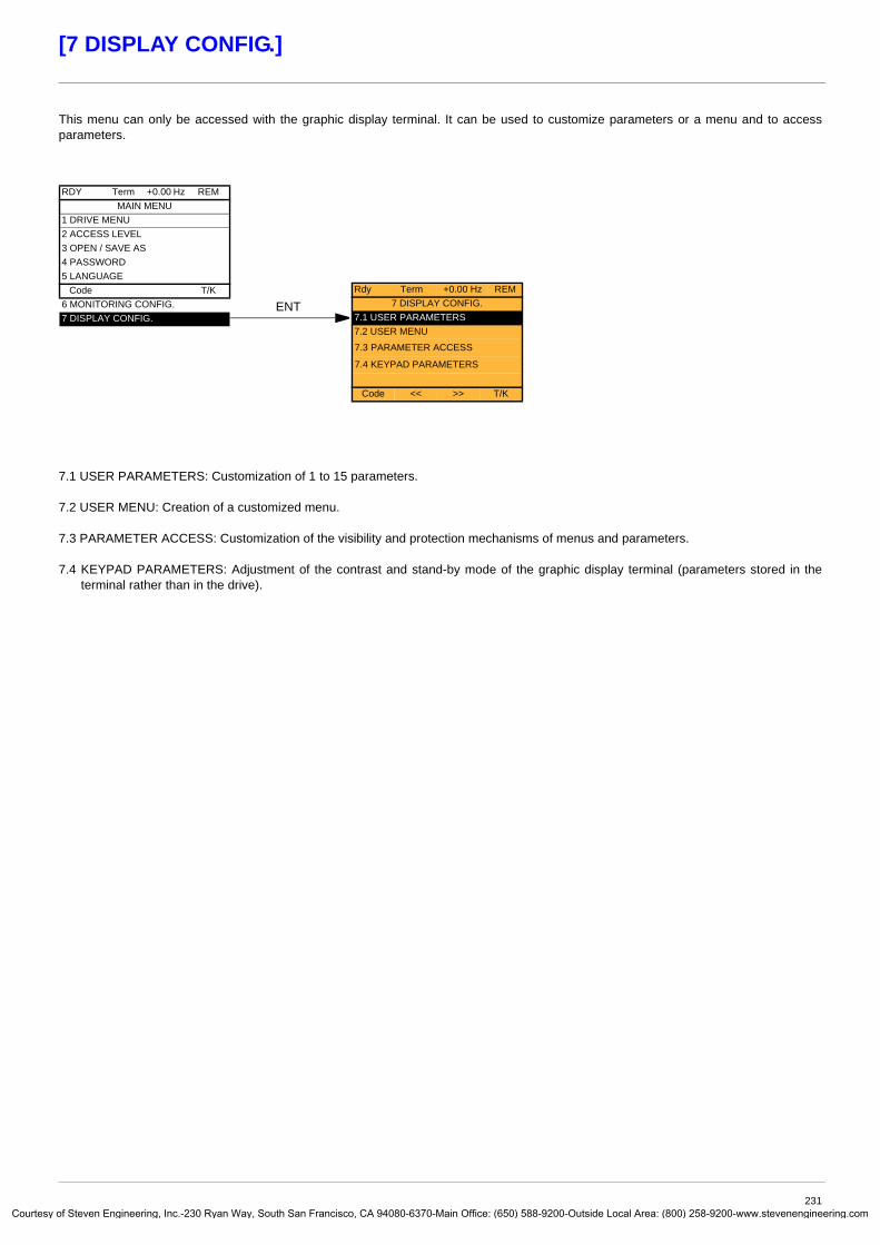
Courtes
[7 DISPLAY CONFIG.]
This menu can only be accessed with the graphic display terminal. It can be used to customize parameters or a menu and to access parameters.
7.1 USER PARAMETERS: Customization of 1 to 15 parameters.
7.2 USER MENU: Creation of a customized menu.
7.3 PARAMETER ACCESS: Customization of the visibility and protection mechanisms of menus and parameters.
7.4 KEYPAD PARAMETERS: Adjustment of the contrast and stand-by mode of the graphic display terminal (parameters stored in the terminal rather than in the drive).
RDY Term +0.00 Hz REMMAIN MENU
1 DRIVE MENU2 ACCESS LEVEL3 OPEN / SAVE AS4 PASSWORD5 LANGUAGE
Code T/K6 MONITORING CONFIG.7 DISPLAY CONFIG.
ENTRdy Term +0.00 Hz REM
7 DISPLAY CONFIG.7.1 USER PARAMETERS7.2 USER MENU
7.3 PARAMETER ACCESS
7.4 KEYPAD PARAMETERS
Code << >> T/K
231y of Steven Engineering, Inc.-230 Ryan Way, South San Francisco, CA 94080-6370-Main Office: (650) 588-9200-Outside Local Area: (800) 258-9200-www.stevenengineering.com

Courtes
[7 DISPLAY CONFIG.]
If [Return std name] = [Yes] the display reverts to standard but the custom settings remain stored.
Selection of 1 to 15 parameters to be customized
Note: The 1st line is [PARAMETER SELECTION] or [RDY Term +0.00 Hz REM] depending on the path (ENT or List).
List of customized parameters
If no custom settings have been made, the standard value appears (names, units, etc.).
Display on 1 or 2 lines of characters
Offsets and coefficients are numerical values. Do not use too high a multiplier (99,999 – max display).
Use F1 to change to ABC, abc, 123, *[-.Use the navigation selector button to increment the character (alphabetical order) and << and >> (F2 and F3) to switch to the next or previous character respectively.
- Standard: use of the factory set unit
- Customized: customization of the unit
-%, mA, etc.: select from drop-down list
Once you have entered the unit, if you press ENT, the Ramp increment screen will re-appear in order to display the name. Press ESC to return to Unit.
The message entered appears while the “View” button is pressed.
Names (USER MENU NAME, DRIVE NAME, configuration, serial no., lines of messages, names of units, etc.) are customized as in the example of the parameter name shown opposite.If no custom settings have been made, the standard value appears (names, units, etc.).Display on 1 or 2 lines of characters.Use F1 to change to ABC, abc, 123, *[-.Use the navigation selector button to increment the character (alphabetical order) and << and >> (F2 and F3) to switch to the next or previous character respectively.
RDY Term +0.00 Hz REM7.1 USER PARAMETERS
Return std name : NoPARAMETER SELECTIONCUSTOMIZED SELECTIONUSER MENU NAMEDEVICE NAME
Code << >> T/KSERVICE MESSAGECONFIGURATION 0CONFIGURATION 1CONFIGURATION 2ATV SERIAL NUMBER
ENT
ENT
ENT
ENT
ENT
ENT
ENT
RDY Term +0.00 Hz REMUnit
StandardCustomized
%mA
T/K
List
PARAMETER SELECTION1.3 SETTINGS
Ramp incrementAccelerationDecelerationAcceleration 2Deceleration 2
List
PARAMETER SELECTION1 DRIVE MENU
1.1 SIMPLY START1.2 MONITORING1.3 SETTINGS1.4 MOTOR CONTROL1.5 INPUTS / OUTPUTS CFG
Code << >> T/K
RDY Term +0.00 Hz REMCUSTOMIZED SELECTION
Ramp incrementAccelerationSpeed prop. gain
Delete
RDY Term +0.00 Hz REMRamp increment
User nameUnitMultiplierDivisorOffset
RDY Term +0.00 Hz REMUser name
1. DRIVE MENUFLOW REFERENCE
Nb characters max. 13ABC << >>
RDY Term +0.00 Hz REMCustomized
1. DRIVE MENULBS
Nb characters max. 3ABC << >>
RDY Term +0.00 Hz REMSERVICE MESSAGE
LINE 1LINE 2LINE 3LINE 4LINE 5View T/K
RDY Term +0.00 Hz REMLINE 2
1. DRIVE MENUFor any service, dial:
Nb characters max. 23ABC << >> T/K
RDY Term +0.00 Hz REMUSER MENU NAME
1. DRIVE MENUFLOW REFERENCE
Nb characters max. 18ABC << >> T/K
232y of Steven Engineering, Inc.-230 Ryan Way, South San Francisco, CA 94080-6370-Main Office: (650) 588-9200-Outside Local Area: (800) 258-9200-www.stevenengineering.com
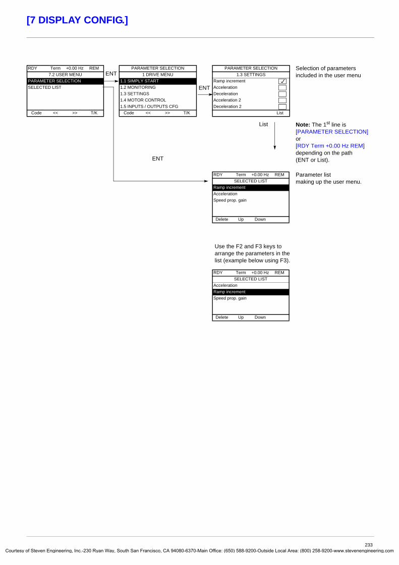
Courtes
[7 DISPLAY CONFIG.]
Selection of parameters included in the user menu
Note: The 1st line is [PARAMETER SELECTION] or [RDY Term +0.00 Hz REM] depending on the path (ENT or List).
Parameter list making up the user menu.
Use the F2 and F3 keys to arrange the parameters in the list (example below using F3).
RDY Term +0.00 Hz REM7.2 USER MENU
PARAMETER SELECTIONSELECTED LIST
Code << >> T/K
ENT
ENT
ENT
PARAMETER SELECTION1 DRIVE MENU
1.1 SIMPLY START1.2 MONITORING1.3 SETTINGS1.4 MOTOR CONTROL1.5 INPUTS / OUTPUTS CFG
Code << >> T/K
PARAMETER SELECTION1.3 SETTINGS
Ramp incrementAccelerationDecelerationAcceleration 2Deceleration 2
List
List
RDY Term +0.00 Hz REMSELECTED LIST
Ramp incrementAccelerationSpeed prop. gain
Delete Up Down
RDY Term +0.00 Hz REMSELECTED LIST
AccelerationRamp incrementSpeed prop. gain
Delete Up Down
233y of Steven Engineering, Inc.-230 Ryan Way, South San Francisco, CA 94080-6370-Main Office: (650) 588-9200-Outside Local Area: (800) 258-9200-www.stevenengineering.com

Courtes
[7 DISPLAY CONFIG.]
Note: The protected parameters are no longer accessible and are not, therefore, displayed for the selected channels.
Selection to display all parameters or only the active parameters.Press ESC to exit this screen.
You remain exclusively in the [1. DRIVE MENU] menu. All menus are selected by default.Press ENT to deselect a menu.Press ENT to reselect a menu.
IMPORTANT: The protected channel (or channels) must be selected, as a protected parameter on a selected channel remains accessible on the channels that are not selected.
In these screens all parameters in the [1. DRIVE MENU] menu can be protected and are displayed for selection, except for the Expert parameters.
Press the All button to select all the parameters. Press the All button again to deselect all the parameters.
RDY Term +0.00 Hz REM7.3 PARAMETER ACCESS
PROTECTIONVISIBILITY
Code << >> T/K
ENT
ENT
RDY Term +0.00 Hz REMVISIBILITY
PARAMETERSMENUS
Code T/K
ENT
ENTRDY Term +0.00 Hz REM
PARAMETERSActiveAll
T/K
ENT
MENUS1. DRIVE MENU
1.1 SIMPLY START1.2 MONITORING1.3 SETTINGS1.4 MOTOR CONTROL1.5 INPUTS / OUTPUTS CFG
RDY Term +0.00 Hz REMPROTECTION
PROTECTED CHANNELSPROTECTED PARAMS
Code T/K
RDY Term +0.00 Hz REMPROTECTED CHANNELS
HMIPOWERSUITEMODBUSCANopenCOM. CARD
Code T/KPROG. CARD
PROTECTED PARAMS1 DRIVE MENU
1.1 SIMPLY START1.2 MONITORING1.3 SETTINGS1.4 MOTOR CONTROL1.5 INPUTS / OUTPUTS CFG
1.7 APPLICATION FUNCT.
ENTPROTECTED PARAMS
1.3 SETTINGSRamp incrementAccelerationDecelerationAcceleration 2Deceleration 2
All
ENT
ENT
PROTECTED PARAMS1.7 APPLICATION FUNCT.
REF. OPERATIONSRAMPSTOP CONFIGURATIONAUTO DC INJECTIONJOG
No selections can be made in this screen if there are no parameters.
PROTECTED PARAMSJOG
JOGJog frequencyJog delay
234y of Steven Engineering, Inc.-230 Ryan Way, South San Francisco, CA 94080-6370-Main Office: (650) 588-9200-Outside Local Area: (800) 258-9200-www.stevenengineering.com

Courtes
[7 DISPLAY CONFIG.]
Name/Description Adjustment range Factory setting
M [Keypad contrast] 0 to 100% 50%
Adjustment of contrast on the graphic display unit
M [Keypad stand-by] [5]
Configuration and adjustment of the graphic display unit's stand-by modev [No]: No stand-by modev [1] to [10]: Number of minutes during which the terminal is to remain idle before stand-by mode is triggered.
After this idle time, the display backlight turns off and the contrast is reduced. The screen returns to normal operation when a key or the navigation button is pressed. It also returns to normal operation if the terminal exits the normal display mode, for example, if a fault occurs.
RDY Term +0.00Hz 0A7.4 KEYPAD PARAMETERS
Keypad contrastKeypad stand-by
Code << >> Quick
235y of Steven Engineering, Inc.-230 Ryan Way, South San Francisco, CA 94080-6370-Main Office: (650) 588-9200-Outside Local Area: (800) 258-9200-www.stevenengineering.com

Courtes
[MULTIPOINT SCREEN]
Communication is possible between a graphic display terminal and a number of drives connected on the same bus. The addresses of the drives must be configured in advance in the [1.9 COMMUNICATION] menu using the [Modbus Address] (Add) parameter, page 213.
When a number of drives are connected to the same display terminal, the terminal automatically displays the following screens:
All menus can be accessed in multipoint mode. Only drive control via the graphic display terminal is not authorized, apart from the Stop key, which locks all the drives.If there is a fault on a drive, this drive is displayed.
Selection of drives for multipoint dialog (select each address and check it by pressing ENT).This screen only appears when making a connection for the first time or if the "Cfg Add" button is pressed in the MULTIPOINT SCREEN below.
Selection of a drive for multipoint dialog.
In multipoint mode, the command channel is not displayed. The state, then the 2 selected parameters and the drive address appear from left to right.
ENT
ESCESC
ENT
Cfg Add
CONNECTION IN PROGRESS
Vxxxxxx
MULTI-POINT ADDRESSESAddress 1Address 2Address 3Address 4Address 5Address 6
MULTIPOINT SCREENRdy 0 Rpm 0 A 2RUN +952 Rpm 101 A 3NLP +1500 Rpm 1250 A 4
Not connected 5Rdy + 0 Rpm 0 A 6
Cfg Add
RUN +952 Rpm 101 A 3Motor speed
Motor current
HOME T/K
+952 rpm
101 A
236y of Steven Engineering, Inc.-230 Ryan Way, South San Francisco, CA 94080-6370-Main Office: (650) 588-9200-Outside Local Area: (800) 258-9200-www.stevenengineering.com

Courtes
Maintenance
ServicingThe Altivar 61 does not require any preventive maintenance. It is nevertheless advisable to perform the following regularly:
• Check the condition and tightness of the connections.• Ensure that the temperature around the unit remains at an acceptable level and that ventilation is effective (average service life of
fans: 3 to 5 years depending on the operating conditions).• Remove any dust from the drive.
Assistance with maintenance, fault displayIf a problem arises during setup or operation, first check that the recommendations relating to the environment, mounting and connections have been observed.
The first fault detected is saved and displayed, and the drive locks.The drive switching to fault mode can be indicated remotely via a logic output or a relay, which can be configured in the [1.5 INPUTS / OUTPUTS CFG] (I-O-) menu, see, for example, [R1 CONFIGURATION] (r1-) page 94.
[1.10 DIAGNOSTICS] menuThis menu can only be accessed with the graphic display terminal. It displays faults and their cause in plain text and can be used to carry out tests, see page 215.
Clearing the faultDisconnect the drive power supply in the event of a non-resettable fault. Wait for the display to disappear completely. Find the cause of the fault in order to correct it.
The drive is unlocked after a fault:• By switching off the drive until the display disappears completely, then switching on again• Automatically in the scenarios described for the [AUTOMATIC RESTART] (Atr-) function, page 189• By means of a logic input or control bit assigned to the [FAULT RESET] (rSt-) function, page 188• By pressing the STOP/RESET button on the graphic display terminal
[1.2 MONITORING] (SUP-) menu:This is used to prevent and find the causes of faults by displaying the drive state and its current values. It can be accessed with the integrated display terminal.
Spares and repairs: Consult Schneider Electric product support.
237y of Steven Engineering, Inc.-230 Ryan Way, South San Francisco, CA 94080-6370-Main Office: (650) 588-9200-Outside Local Area: (800) 258-9200-www.stevenengineering.com

Courtes
Faults – Causes – Remedies
Starter does not start, no fault displayed• If the display does not light up, check the power supply to the drive.• The assignment of the “Fast stop” or “Freewheel” functions will prevent the drive starting if the corresponding logic inputs are not
powered up. The ATV61 then displays [Freewheel] (nSt) in freewheel stop and [Fast stop] (FSt) in fast stop. This is normal since these functions are active at zero so that the drive will be stopped safely if there is a wire break.
• Make sure that the run command input or inputs are activated in accordance with the selected control mode ([2/3 wire control] (tCC) and [2 wire type] (tCt) parameters, page 80).
• If the reference channel or command channel is assigned to a communication bus, when the power supply is connected, the drive will display [Freewheel] (nSt) and remain in stop mode until the communication bus sends a command.
Faults, which cannot be reset automaticallyThe cause of the fault must be removed before resetting by turning off and then back on. AI2F, EnF, SOF, SPF, and tnF faults can also be reset remotely by means of a logic input or control bit ([Fault reset] (rSF) parameter, page 188).EnF, InFA, InFb, SOF, SPF, and tnF faults can be inhibited and cleared remotely by means of a logic input or control bit ([Fault inhibit assign.] (InH) parameter, page 199).
Fault Name Probable cause Remedy
AI2F [AI2 input] • Non-conforming signal on analog input AI2
• Check the wiring of analog input AI2 and the value of the signal
• If necessary, modify the fault configuration via [AI2 4-20mA loss] (LFL2), page 198
bOF [DBR overload] • The braking resistor is under excessive stress
• Check the size of the resistor and wait for it to cool down• Check the [DB Resistor Power] (brP) and [DB Resistor value]
(brU) parameters, page 204.
bUF [DB unit sh. Circuit] • Short-circuit output from braking unit• Braking unit not connected
• Check the wiring of the braking unit and the resistor• Check the braking resistor• The monitoring of this fault must be disabled by the [Brake
res. fault Mgt] (bUb) parameter, page 204 if there is no braking unit or resistor connected to the drive, at and above 55 kW (75 HP) for ATV61HpppM3X and at and above 90 kW (120 HP) for ATV61HpppN4.
CrF1 [Precharge] • Load relay control fault or charging resistor damaged
• Switch the drive off and then back on again• Check the internal connections• Inspect/repair the drive
CrF2 [Thyr. soft charge] • DC bus charging fault (thyristors)
EEF1 [Control Eeprom] • Internal memory fault, control card • Check the environment (electromagnetic compatibility)• Turn off, reset, return to factory settings• Inspect/repair the drive
EEF2 [Power Eeprom] • Internal memory fault, power card
EnF [Encoder] • Encoder feedback fault • Check [Number of pulses] (PGI) and [Encoder type] (EnS) page 73
• Check that the encoder's mechanical and electrical operation, its power supply and connections are all correct
• If necessary, reverse the direction of rotation of the motor ([Output Ph rotation] (PHr) parameter, page 66) or the encoder signals
FCF1 [Out. contact. stuck]
• The output contactor remains closed although the opening conditions have been met
• Check the contactor and its wiring • Check the feedback circuit
Fd2 [Damper open] • The damper remains open although the closing conditions have been met
• Check the damper and its wiring• Check the feedback circuit• Check the time delay for the function, page 172
HdF [IGBT desaturation]
• Short-circuit or grounding at the drive output
• Check the cables connecting the drive to the motor, and the insulation of the motor
• Perform the diagnostic tests via the [1.10 DIAGNOSTICS] menu.
238y of Steven Engineering, Inc.-230 Ryan Way, South San Francisco, CA 94080-6370-Main Office: (650) 588-9200-Outside Local Area: (800) 258-9200-www.stevenengineering.com

Courtes
Faults – Causes – Remedies
Faults, which cannot be reset automatically (continued)
Fault Name Probable cause Remedy
ILF [internal com. link] • Communication fault between option card and drive
• Check the environment (electromagnetic compatibility)• Check the connections• Check that no more than 2 option cards (max. permitted)
have been installed on the drive• Replace the option card• Inspect/repair the drive
InF1 [Rating error] • The power card is different from the card stored
• Check the reference of the power card
InF2 [Incompatible PB] • The power card is incompatible with the control card
• Check the reference of the power card and its compatibility
InF3 [Internal serial link] • Communication fault between the internal cards
• Check the internal connections• Inspect/repair the drive
InF4 [Internal MFG area] • Internal data inconsistent • Recalibrate the drive (performed by Schneider Electric Product Support)
InF6 [Internal-option] • The option installed in the drive is not recognized
• Check the reference and compatibility of the option
InF7 [Internal-hard init.] • Initialization of the drive is incomplete • Turn off and reset
InF8 [Internal-ctrl supply]
• The control power supply is incorrect • Check the control section power supply
InF9 [Internal- I measure]
• The current measurements are incorrect • Replace the current sensors or the power card• Inspect/repair the drive
InFA [Internal-mains circuit]
• The input stage is not operating correctly
• Perform the diagnostic tests via the [1.10 DIAGNOSTICS] menu.
• Inspect/repair the drive
InFb [Internal- th. sensor]
• The drive temperature sensor is not operating correctly
• The braking unit's temperature sensor is not operating correctly
• Replace the temperature sensor• Inspect/repair the drive• Replace the braking unit's temperature sensor• Inspect/repair the braking unit• The monitoring of this fault must be disabled by the [Brake
res. fault Mgt] (bUb) parameter, page 204 if there is no braking unit connected to the drive
InFC [Internal-time meas.]
• Fault on the electronic time measurement component
• Inspect/repair the drive
InFE [internal- CPU] • Internal microprocessor fault • Turn off and reset. Inspect/repair the drive
OCF [Overcurrent] • Parameters in the [SETTINGS] (SEt-) and [1.4 MOTOR CONTROL] (drC-) menus are not correct
• Inertia or load too high• Mechanical locking
• Check the parameters • Check the size of the motor/drive/load• Check the state of the mechanism
PrF [Power removal] • Fault with the drive’s “Power removal” safety function
• Inspect/repair the drive
SCF1� [Motor short circuit] • Short-circuit or grounding at the drive output
• Significant earth leakage current at the drive output if several motors are connected in parallel
• Check the cables connecting the drive to the motor, and the insulation of the motor
• Perform the diagnostic tests via the [1.10 DIAGNOSTICS] menu.
• Reduce the switching frequency• Connect chokes in series with the motor• Check the adjustment of speed loop and brake
SCF2 [Impedant sh. circuit]
SCF3 [Ground short circuit]
SOF [Overspeed] • Instability or driving load too high • Check the motor, gain and stability parameters• Add a braking resistor• Check the size of the motor/drive/load• Check the parameter settings for the [FREQUENCY
METER] (FqF-) function, page 203, if it is configured
239y of Steven Engineering, Inc.-230 Ryan Way, South San Francisco, CA 94080-6370-Main Office: (650) 588-9200-Outside Local Area: (800) 258-9200-www.stevenengineering.com

Courtes
Faults – Causes – Remedies
Faults, which cannot be reset automatically (continued)
Fault Name Probable cause Remedy
SPF [Speed fdback loss]
• Encoder feedback signal missing
• No signal on "Pulse input", if the input is used for speed measurement
• Check the wiring between the encoder and the drive• Check the encoder• Check the wiring of the input and the detector used
tnF [Auto-tuning] • Special motor or motor whose power is not suitable for the drive
• Motor not connected to the drive
• Check that the motor/drive are compatible•• Check that the motor is present during auto-tuning• If an output contactor is being used, close it during auto-
tuning
240y of Steven Engineering, Inc.-230 Ryan Way, South San Francisco, CA 94080-6370-Main Office: (650) 588-9200-Outside Local Area: (800) 258-9200-www.stevenengineering.com

Courtes
Faults – Causes – Remedies
Faults that can be reset with the automatic restart function, after the cause has disappearedThese faults can also be reset by turning on and off or by means of a logic input or control bit ([Fault reset] (rSF) parameter, page 188).APF, CnF, COF, EPF1, EPF2, FCF2, Fd1, LFF2, LFF3, LFF4, nFF, ObF, OHF, OLC, OLF, OPF1, OPF2, OSF, OtF1, OtF2, OtFL, PHF, PtF1, PtF2, PtFL, SLF1, SLF2, SLF3, SPIF, SSF, tJF, and ULF faults can be inhibited and cleared remotely by means of a logic input or control bit ([Fault inhibit assign.] (InH) parameter, page 199).
Fault Name Probable cause Remedy
APF [Application fault] • Controller Inside card fault • Please refer to the card documentation
CnF [Com. network] • Communication fault on communication card
• Check the environment (electromagnetic compatibility)• Check the wiring• Check the time-out• Replace the option card• Inspect/repair the drive
COF [CAN com.] • Interruption in communication on the CANopen bus
• Check the communication bus• Check the time-out• Refer to the CANopen User's Manual
EPF1� [External flt-LI/Bit] • Fault triggered by an external device, depending on user
• Check the device, which caused the fault, and reset
EPF2 [External fault com.]
• Fault triggered by a communication network
• Check for the cause of the fault and reset
FCF2 [Out. contact. open.]
• The output contactor remains open although the closing conditions have been met.
• Check the contactor and its wiring • Check the feedback circuit
Fd1 [Damper stuck] • The damper remains closed although the opening conditions have been met
• Check the damper and its wiring• Check the feedback circuit• Check the time delay for the function, page 172
LCF [input contactor] • The drive is not turned on even though [Mains V. time out] (LCt) has elapsed.
• Check the contactor and its wiring • Check the time-out• Check the line/contactor/drive connection
LFF2
LFF3
LFF4
[AI2 4-20mA loss] [AI3 4-20mA loss] [AI4 4-20mA loss]
• Loss of the 4-20 mA reference on analog input AI2, AI3 or AI4
• Check the connection on the analog inputs• If necessary, modify the fault configuration via [AIx 4-20mA
loss] (LFLx), page 198
nFF [No Flow Fault] • Zero fluid • Check and rectify the cause of the fault.• Check the zero fluid detection parameters page 181.
ObF [Overbraking] • Braking too sudden or driving load • Increase the deceleration time• Install a braking resistor if necessary• Activate the [Dec ramp adapt.] (brA) function, page 132,
if it is compatible with the application.
OHF [Drive overheat] • Drive temperature too high • Check the motor load, the drive ventilation and the ambient temperature. Wait for the drive to cool down before restarting
OLC [Proc. Overload Flt] • Process overload • Check and remove the cause of the overload.• Check the parameters of the [PROCESS UNDERLOAD]
(OLd-) function, page 208.
OLF [Motor overload] • Triggered by excessive motor current • Check the setting of the motor thermal protection, check the motor load. Wait for the drive to cool down before restarting
OPF1 [1 motor phase loss]
• Loss of one phase at drive output • Check the connections from the drive to the motor
241y of Steven Engineering, Inc.-230 Ryan Way, South San Francisco, CA 94080-6370-Main Office: (650) 588-9200-Outside Local Area: (800) 258-9200-www.stevenengineering.com

Courtes
Faults – Causes – Remedies
Faults that can be reset with the automatic restart function, after the cause has disappeared (continued)
Fault Name Probable cause Remedy
OPF2 [3 motor phase loss] • Motor not connected or motor power too low
• Output contactor open• Instantaneous instability in the
motor current
• Check the connections from the drive to the motor• If an output contactor is being used, parameterize [Output
Phase Loss] (OPL) = [Output cut] (OAC), page 192• Test on a low power motor or without a motor: In factory
settings mode, motor phase loss detection is active [Output Phase Loss] (OPL) = [Yes] (YES). To check the drive in a test or maintenance environment, without having to use a motor with the same rating as the drive (in particular for high power drives), deactivate motor phase loss detection [Output Phase Loss] (OPL) = [No] (nO)
• Check and optimize the [IR compensation] (UFr) page 71, [Rated motor volt.] (UnS) and [Rated mot. current] (nCr) parameters, page 64, and perform [Auto tuning] (tUn), page 66.
OSF [Mains overvoltage] • Line voltage too high• Disturbed line supply
• Check the line voltage
OtF1 [PTC1 overheat] • Overheating of the PTC1 probes detected
• Check the motor load and motor size• Check the motor ventilation• Wait for the motor to cool before restarting• Check the type and state of the PTC probesOtF2 [PTC2 overheat] • Overheating of the PTC2 probes
detected
OtFL [LI6=PTC overheat] • Overheating of PTC probes detected on input LI6
PtF1 [PTC1 probe] • PTC1 probes open or short-circuited
• Check the PTC probes and the wiring between them and the motor/drive
PtF2 [PTC2 probe] • PTC2 probes open or short-circuited
PtFL [LI6=PTC probe] • PTC probes on input LI6 open or short-circuited
SCF4 [IGBT short circuit] • Power component fault • Perform a test via the [1.10 DIAGNOSTICS] menu.• Inspect/repair the drive
SCF5 [Motor short circuit] • Short-circuit at drive output • Check the cables connecting the drive to the motor, and the motor’s insulation
• Perform tests via the [1.10 DIAGNOSTICS] menu.• Inspect/repair the drive
SLF1 [Modbus com.] • Interruption in communication on the Modbus bus
• Check the communication bus• Check the time-out• Refer to the Modbus User's Manual
SLF2 [PowerSuite com.] • Fault communicating with PowerSuite
• Check the PowerSuite connecting cable• Check the time-out
SLF3 [HMI com.] • Fault communicating with the graphic display terminal
• Check the terminal connection• Check the time-out
SPIF [PI Feedback] • PID feedback below lower limit • Check the PID function feedback.• Check the PID feedback supervision threshold and time delay,
page 155.
SSF [Torque/current lim] • Switch to torque limitation • Check if there are any mechanical problems• Check the parameters of [TORQUE LIMITATION]
(tLA-) page 164 and the parameters of the [TORQUE OR I LIM. DETECT.] (tId-) fault, page 201).
tJF [IGBT overheat] • Drive overheated • Check the size of the load/motor/drive• Reduce the switching frequency• Wait for the motor to cool before restarting
ULF [Proc. Underload Flt] • Process underload • Check and remove the cause of the underload.• Check the parameters of the [PROCESS OVERLOAD] (ULd-)
function, page 207.
242y of Steven Engineering, Inc.-230 Ryan Way, South San Francisco, CA 94080-6370-Main Office: (650) 588-9200-Outside Local Area: (800) 258-9200-www.stevenengineering.com

Courtes
Faults – Causes – Remedies
Faults that can be reset as soon as their causes disappear
The USF fault can be inhibited and cleared remotely by means of a logic input or control bit ([Fault inhibit assign.] (InH) parameter, page 199).
Option card changed or removedWhen an option card is removed or replaced by another, the drive locks in [Incorrect config.] (CFF) fault mode on power-up. If the card has been deliberately changed or removed, the fault can be cleared by pressing the ENT key twice, which causes the factory settings to be restored (see page 220) for the parameter groups affected by the card. These are as follows:
Card replaced by a card of the same type• I/O cards: [Drive menu] (drM)• Encoder cards: [Drive menu] (drM)• Communication cards: Only the parameters that are specific to communication cards• Controller Inside cards: [Prog. card menu] (PLC)
Card removed (or replaced by a different type of card)• I/O card: [Drive menu] (drM)• Encoder card: [Drive menu] (drM)• Communication card: [Drive menu] (drM) and parameters specific to communication cards• Controller Inside card: [Drive menu] (drM) and [Prog. card menu] (PLC)
Control card changedWhen a control card is replaced by a control card configured on a drive with a different rating, the drive locks in [Power Ident] (PrtF) fault mode on power-up. If the card has been deliberately changed, the fault can be cleared by modifying the [Power Identification] (Prt)parameter, page 72, which causes all the factory settings to be restored.
Fault Name Probable cause Remedy
CFF [Incorrect config.] • changed or removed
• The current configuration is inconsistent
• Check that there are no card errors.• In the event of the option card being changed/removed
deliberately, see the remarks below
• Return to factory settings or retrieve the backup configuration, if it is valid (see page 220)
CFI [Invalid config.] • Invalid configuration The configuration loaded in the drive via the bus or communication network is inconsistent.
• Check the configuration loaded previously• Load a compatible configuration
HCF [Cards pairing] • The [CARDS PAIRING] (PPI-) function, page 205, has been configured and a drive card has been changed
• In the event of a card error, reinsert the original card • Confirm the configuration by entering the [Pairing password]
(PPI) if the card was changed deliberately
PHF [Input phase loss] • Drive incorrectly supplied or a fuse blown
• Failure of one phase• 3-phase ATV61 used on a single-
phase line supply• Unbalanced loadThis protection only operates with the drive on load
• Check the power connection and the fuses.
• Use a 3-phase line.
• Disable the fault by [Input phase loss] (IPL) = [No] (nO). (page 193)
PrtF [Power Ident] • The [Power Identification] (Prt) parameter, page 72, is incorrect.
• Control card replaced by a control card configured on a drive with a different rating
• Enter the correct parameter (reserved for Schneider Electric product support).
• Check that there are no card errors.• In the event of the control card being changed deliberately,
see the remarks below
USF [Undervoltage] • Line supply too low• Transient voltage dip• Damaged pre-charge resistor
• Check the voltage and the parameters of [UNDERVOLTAGE MGT] (USb-), page 196
• Replace the pre-charge resistor• Inspect/repair the drive
243y of Steven Engineering, Inc.-230 Ryan Way, South San Francisco, CA 94080-6370-Main Office: (650) 588-9200-Outside Local Area: (800) 258-9200-www.stevenengineering.com

Courtes
User settings tables
[1.1 SIMPLY START] (SIM-) menu
Functions assigned to I/O
Code Name Factory setting Customer setting
tCC [2/3 wire control] [2 wire] (2C)
CFG [Macro configuration] [Start/Stop] (StS)
bFr [Standard mot. freq] [50 Hz] (50)
IPL [Input phase loss] According to drive rating
nPr [Rated motor power] According to drive rating
UnS [Rated motor volt.] According to drive rating
nCr [Rated mot. current] According to drive rating
FrS [Rated motor freq.] 50 Hz
nSP [Rated motor speed] According to drive rating
tFr [Max frequency] 60 Hz
PHr [Output Ph rotation] ABC
ItH [Mot. therm. current] According to drive rating
ACC [Acceleration] 3.0 s
dEC [Deceleration] 3.0 s
LSP [Low speed] 0
HSP [High speed] 50 Hz
Inputs Outputs
Functions assigned Inputs Outputs
Functions assigned
LI1 LO1
LI2 LO2
LI3 LO3
LI4 LO4
LI5 AI1
LI6 AI2
LI7 AI3
LI8 AI4
LI9 R1
LI10 R2
LI11 R3
LI12 R4
LI13 RP
LI14 Encoder
244y of Steven Engineering, Inc.-230 Ryan Way, South San Francisco, CA 94080-6370-Main Office: (650) 588-9200-Outside Local Area: (800) 258-9200-www.stevenengineering.com

Courtes
User settings tables
Other parameters (table to be created by the user)
Code Name Customer setting Code Name Customer setting
245y of Steven Engineering, Inc.-230 Ryan Way, South San Francisco, CA 94080-6370-Main Office: (650) 588-9200-Outside Local Area: (800) 258-9200-www.stevenengineering.com

Courtes
Index of functions
+/- speed 141+/- speed around a reference 143[2 wire] (2C) 34[2nd CURRENT LIMIT.] 166[3 wire] (3C) 34[AUTO DC INJECTION] 135[Auto tuning] 36[AUTO TUNING BY LI] 179[AUTOMATIC RESTART] 189[CATCH ON THE FLY] 190Command and reference channels 109Damper control 171Deferred stop on thermal alarm 194Direct power supply via DC bus 184[DRIVE OVERHEAT] 193[ENCODER CONFIGURATION] 92[1.12 FACTORY SETTINGS] (FCS-) 218[FAULT RESET] 188Flow limitation 182[FLUXING BY LI] 146[JOG] 137[1.7 APPLICATION FUNCT.] (FUn-) 167[1.4 MOTOR CONTROL] (drC-) 73Motor or configuration switching [MULTIMOTORS/CONFIG.] 176Motor thermal protection 191[Noise reduction] 76Output contactor command 169Parameter set switching [PARAM. SET SWITCHING] 173[4. PASSWORD] (COd-) 225PID feedback supervision 154PID regulator 147Preset speeds 138Process overload fault 208Process underload fault 206PTC probes 186[RAMP] 129Reference saving: 145[REFERENCE SWITCH.] 127[RP CONFIGURATION] 90Skip frequencies 61Sleep/Wake-up 157[1.7 APPLICATION FUNCT.] (FUn-) 160[STOP CONFIGURATION] 133Summing input/Subtracting input/Multiplier 126Torque limitation 163Use of the "Pulse input" to measure the speed of rotation of the motor 202Zero fluid or zero flow detection via sensor 180
246y of Steven Engineering, Inc.-230 Ryan Way, South San Francisco, CA 94080-6370-Main Office: (650) 588-9200-Outside Local Area: (800) 258-9200-www.stevenengineering.com

Courtes
Index of parameter codes
Code Page
[1.1
SIM
PLY
STA
RT]
(S
IM-
)
[1.2
MO
NIT
OR
ING
] (S
UP-
)
[1.3
SET
TIN
GS]
(S
Et-
)
[1.4
MO
TOR
CO
NTR
OL]
(d
rC-
)
[1.5
INPU
TS /
OU
TPU
TS C
FG]
(I-O-
)
[1.6
CO
MM
AN
D]
(CtL-
)
[1.7
APP
LIC
ATI
ON
FU
NC
T.]
(FUn-
)
[1.8
FA
ULT
MA
NA
GEM
ENT]
(F
Lt-
)
[1.9
CO
MM
UN
ICA
TIO
N]
(COM-
)
[1.1
2 FA
CTO
RY
SETT
ING
S]
(FCS-
)
[4 P
ASS
WO
RD
] (C
Od-
)
A1C- 107
A2C- 107
A3C- 107
AC2 48 131 144 153
ACC 37 48 129
AdC 135
AdCO 213
Add 213
AI1A 45 85
AI1E 85
AI1F 85
AI1S 85
AI1t 85
AI2A 45 86
AI2E 86
AI2F 86
AI2L 86
AI2S 86
AI2t 86
AI3A 45 87
AI3E 87
AI3F 87
AI3L 87
AI3S 87
AI3t 87
AI4A 45 88
AI4E 88
AI4F 88
AI4L 88
AI4S 88
AI4t 88
AICI 89 151
ALGr 46
AMOA 213
AMOC 213
247y of Steven Engineering, Inc.-230 Ryan Way, South San Francisco, CA 94080-6370-Main Office: (650) 588-9200-Outside Local Area: (800) 258-9200-www.stevenengineering.com
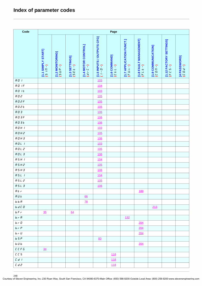
Courtes
AO1 103
AO1F 104
AO1t 103
AO2 105
AO2F 105
AO2t 105
AO3 106
AO3F 106
AO3t 106
AOH1 103
AOH2 105
AOH3 106
AOL1 103
AOL2 105
AOL3 106
ASH1 104
ASH2 105
ASH3 106
ASL1 104
ASL2 105
ASL3 106
Atr 189
AUt 66
bbA 78
bdCO 213
bFr 35 64
brA 132
brO 204
brP 204
brU 204
bSP 83
bUb 204
CCFG 34
CCS 118
Cd1 118
Cd2 118
Index of parameter codes
Code Page
[1.1
SIM
PLY
STA
RT]
(S
IM-
)
[1.2
MO
NIT
OR
ING
] (S
UP-
)
[1.3
SET
TIN
GS]
(S
Et-
)
[1.4
MO
TOR
CO
NTR
OL]
(d
rC-
)
[1.5
INPU
TS /
OU
TPU
TS C
FG]
(I-O-
)
[1.6
CO
MM
AN
D]
(CtL-
)
[1.7
APP
LIC
ATI
ON
FU
NC
T.]
(FUn-
)
[1.8
FA
ULT
MA
NA
GEM
ENT]
(F
Lt-
)
[1.9
CO
MM
UN
ICA
TIO
N]
(COM-
)
[1.1
2 FA
CTO
RY
SETT
ING
S]
(FCS-
)
[4 P
ASS
WO
RD
] (C
Od-
)
248y of Steven Engineering, Inc.-230 Ryan Way, South San Francisco, CA 94080-6370-Main Office: (650) 588-9200-Outside Local Area: (800) 258-9200-www.stevenengineering.com

Courtes
CFG 34
CFPS 46
CHA1 174
CHA2 174
CHCF 117
CHI 183
CHM 179
CHt 62 183
CL2 54 166
CLI 54 75 166
CLL 200
CLO- 46
CnF1 179
CnF2 179
CnFS 46
COd 226
COd2 226
COL 200
COP 119
CrH2 86
CrH3 87
CrH4 88
CrL2 86
CrL3 87
CrL4 88
CSt 226
Ctd 59
CtdL 59
Ctt 67
dA2 128
dA3 128
dAM 172
dAS 170
dbS 170
dCF 52 133 210
dCI 134
Index of parameter codes
Code Page
[1.1
SIM
PLY
STA
RT]
(S
IM-
)
[1.2
MO
NIT
OR
ING
] (S
UP-
)
[1.3
SET
TIN
GS]
(S
Et-
)
[1.4
MO
TOR
CO
NTR
OL]
(d
rC-
)
[1.5
INPU
TS /
OU
TPU
TS C
FG]
(I-O-
)
[1.6
CO
MM
AN
D]
(CtL-
)
[1.7
APP
LIC
ATI
ON
FU
NC
T.]
(FUn-
)
[1.8
FA
ULT
MA
NA
GEM
ENT]
(F
Lt-
)
[1.9
CO
MM
UN
ICA
TIO
N]
(COM-
)
[1.1
2 FA
CTO
RY
SETT
ING
S]
(FCS-
)
[4 P
ASS
WO
RD
] (C
Od-
)
249y of Steven Engineering, Inc.-230 Ryan Way, South San Francisco, CA 94080-6370-Main Office: (650) 588-9200-Outside Local Area: (800) 258-9200-www.stevenengineering.com

Courtes
dCO 184
dE2 48 131, 144
dEC 37 48 129
dFb 172
dFL 62 183
dLr 226
dO1 100
dO1d 100
dO1H 100
dO1S 100
dSI 144
dSP 142
EFI 93
EFr 93
EIL 93
EnC 74 92
EnS 73 92
EnU 74 93
EPL 195
ErCO 213
EtF 195
F1 68
F2 68
F2d 59
F2dL 59
F3 68
F4 69
F5 69
Fbtd 172
FCP 69
FCSI 220
FdL 209
Fdt 203
FFd 62 162
FFt 60 133
Index of parameter codes
Code Page
[1.1
SIM
PLY
STA
RT]
(S
IM-
)
[1.2
MO
NIT
OR
ING
] (S
UP-
)
[1.3
SET
TIN
GS]
(S
Et-
)
[1.4
MO
TOR
CO
NTR
OL]
(d
rC-
)
[1.5
INPU
TS /
OU
TPU
TS C
FG]
(I-O-
)
[1.6
CO
MM
AN
D]
(CtL-
)
[1.7
APP
LIC
ATI
ON
FU
NC
T.]
(FUn-
)
[1.8
FA
ULT
MA
NA
GEM
ENT]
(F
Lt-
)
[1.9
CO
MM
UN
ICA
TIO
N]
(COM-
)
[1.1
2 FA
CTO
RY
SETT
ING
S]
(FCS-
)
[4 P
ASS
WO
RD
] (C
Od-
)
250y of Steven Engineering, Inc.-230 Ryan Way, South San Francisco, CA 94080-6370-Main Office: (650) 588-9200-Outside Local Area: (800) 258-9200-www.stevenengineering.com

Courtes
FLI 146
FLO 214
FLOC 214
FLOt 214
FLr 190
FLU 55 146
FPI 153
FqA 203
FqC 203
FqF 203
FqL 59
FqS 44, 46
Fr1 117
Fr1b 127
Fr2 118
FrH 46
FrS 35 64
FrSS 70
Frt 131
FrY- 220
FSt 133
Ftd 59
FtdL 59
FtO 62 208
FtU 61 207
GFS 220
HSP 37 49
IdA 72
IdC 52 134 210
IdC2 52 134 210
IdM 72
InH 199
InHr 199
InHS 199
Inr 48 129
IntP 164
Index of parameter codes
Code Page
[1.1
SIM
PLY
STA
RT]
(S
IM-
)
[1.2
MO
NIT
OR
ING
] (S
UP-
)
[1.3
SET
TIN
GS]
(S
Et-
)
[1.4
MO
TOR
CO
NTR
OL]
(d
rC-
)
[1.5
INPU
TS /
OU
TPU
TS C
FG]
(I-O-
)
[1.6
CO
MM
AN
D]
(CtL-
)
[1.7
APP
LIC
ATI
ON
FU
NC
T.]
(FUn-
)
[1.8
FA
ULT
MA
NA
GEM
ENT]
(F
Lt-
)
[1.9
CO
MM
UN
ICA
TIO
N]
(COM-
)
[1.1
2 FA
CTO
RY
SETT
ING
S]
(FCS-
)
[4 P
ASS
WO
RD
] (C
Od-
)
251y of Steven Engineering, Inc.-230 Ryan Way, South San Francisco, CA 94080-6370-Main Office: (650) 588-9200-Outside Local Area: (800) 258-9200-www.stevenengineering.com
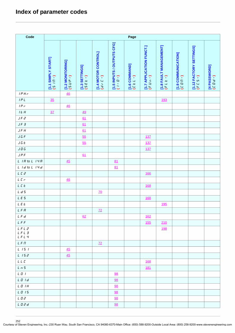
Courtes
IPHr 46
IPL 35 193
IPr 46
ItH 37 49
JF2 61
JF3 61
JFH 61
JGF 55 137
JGt 55 137
JOG 137
JPF 61
L1A to L14A 45 81
L1d to L14d 81
LC2 166
LCr 46
LCt 168
LdS 70
LES 168
LEt 195
LFA 72
LFd 62 162
LFF 155 210
LFL2 LFL3 LFL4
198
LFM 72
LIS1 45
LIS2 45
LLC 168
LnS 181
LO1 98
LO1d 98
LO1H 98
LO1S 98
LO2 98
LO2d 98
Index of parameter codes
Code Page
[1.1
SIM
PLY
STA
RT]
(S
IM-
)
[1.2
MO
NIT
OR
ING
] (S
UP-
)
[1.3
SET
TIN
GS]
(S
Et-
)
[1.4
MO
TOR
CO
NTR
OL]
(d
rC-
)
[1.5
INPU
TS /
OU
TPU
TS C
FG]
(I-O-
)
[1.6
CO
MM
AN
D]
(CtL-
)
[1.7
APP
LIC
ATI
ON
FU
NC
T.]
(FUn-
)
[1.8
FA
ULT
MA
NA
GEM
ENT]
(F
Lt-
)
[1.9
CO
MM
UN
ICA
TIO
N]
(COM-
)
[1.1
2 FA
CTO
RY
SETT
ING
S]
(FCS-
)
[4 P
ASS
WO
RD
] (C
Od-
)
252y of Steven Engineering, Inc.-230 Ryan Way, South San Francisco, CA 94080-6370-Main Office: (650) 588-9200-Outside Local Area: (800) 258-9200-www.stevenengineering.com
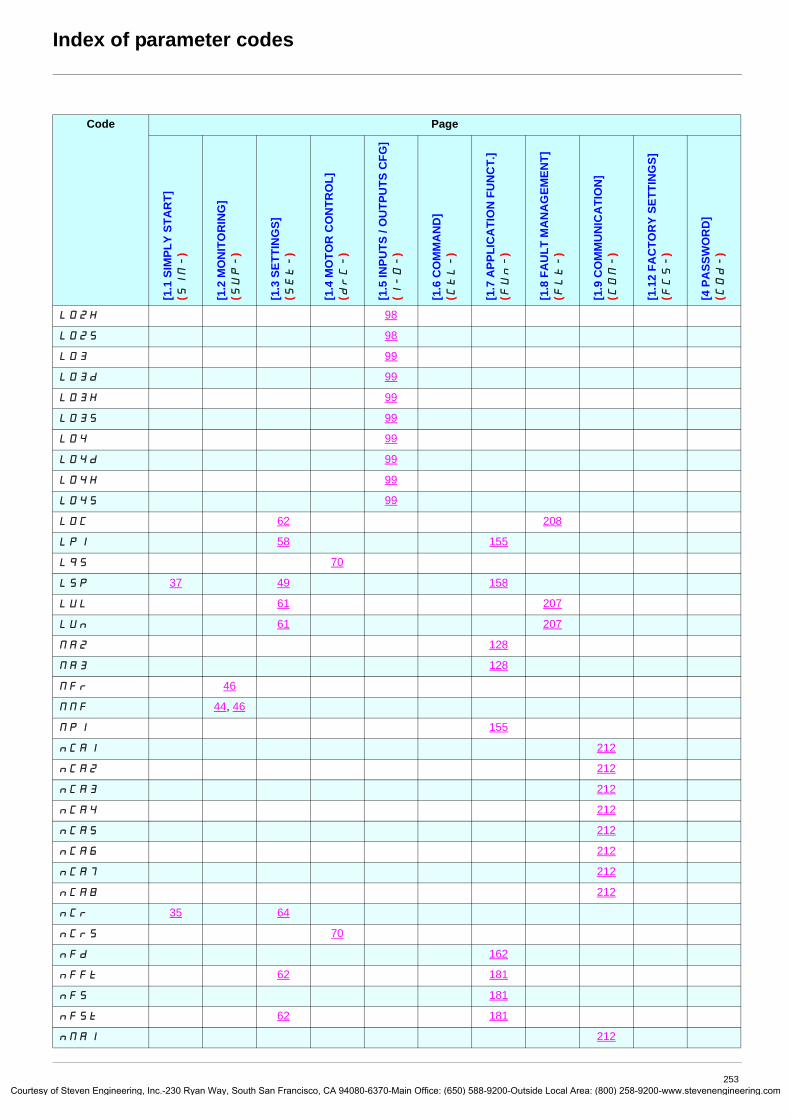
Courtes
LO2H 98
LO2S 98
LO3 99
LO3d 99
LO3H 99
LO3S 99
LO4 99
LO4d 99
LO4H 99
LO4S 99
LOC 62 208
LPI 58 155
LqS 70
LSP 37 49 158
LUL 61 207
LUn 61 207
MA2 128
MA3 128
MFr 46
MMF 44, 46
MPI 155
nCA1 212
nCA2 212
nCA3 212
nCA4 212
nCA5 212
nCA6 212
nCA7 212
nCA8 212
nCr 35 64
nCrS 70
nFd 162
nFFt 62 181
nFS 181
nFSt 62 181
nMA1 212
Index of parameter codes
Code Page
[1.1
SIM
PLY
STA
RT]
(S
IM-
)
[1.2
MO
NIT
OR
ING
] (S
UP-
)
[1.3
SET
TIN
GS]
(S
Et-
)
[1.4
MO
TOR
CO
NTR
OL]
(d
rC-
)
[1.5
INPU
TS /
OU
TPU
TS C
FG]
(I-O-
)
[1.6
CO
MM
AN
D]
(CtL-
)
[1.7
APP
LIC
ATI
ON
FU
NC
T.]
(FUn-
)
[1.8
FA
ULT
MA
NA
GEM
ENT]
(F
Lt-
)
[1.9
CO
MM
UN
ICA
TIO
N]
(COM-
)
[1.1
2 FA
CTO
RY
SETT
ING
S]
(FCS-
)
[4 P
ASS
WO
RD
] (C
Od-
)
253y of Steven Engineering, Inc.-230 Ryan Way, South San Francisco, CA 94080-6370-Main Office: (650) 588-9200-Outside Local Area: (800) 258-9200-www.stevenengineering.com

Courtes
nMA2 212
nMA3 212
nMA4 212
nMA5 212
nMA6 212
nMA7 212
nMA8 212
nPr 35 64
nrd 76
nSL 72
nSP 35 65
nSPS 70
nSt 133
o06 46
o02 46
o03 46
o04 46
o05 46
OCC 170
OdL 208
Odt 192
OFI 75
OHL 193
OLL 192
OPL 192
OPr 46
Otr 46
PAH 57 152
PAL 57 152
PAU 153
PEr 58 152
PEt 46
PFI 90
PFL 68
PFr 90
PGA 93
Index of parameter codes
Code Page
[1.1
SIM
PLY
STA
RT]
(S
IM-
)
[1.2
MO
NIT
OR
ING
] (S
UP-
)
[1.3
SET
TIN
GS]
(S
Et-
)
[1.4
MO
TOR
CO
NTR
OL]
(d
rC-
)
[1.5
INPU
TS /
OU
TPU
TS C
FG]
(I-O-
)
[1.6
CO
MM
AN
D]
(CtL-
)
[1.7
APP
LIC
ATI
ON
FU
NC
T.]
(FUn-
)
[1.8
FA
ULT
MA
NA
GEM
ENT]
(F
Lt-
)
[1.9
CO
MM
UN
ICA
TIO
N]
(COM-
)
[1.1
2 FA
CTO
RY
SETT
ING
S]
(FCS-
)
[4 P
ASS
WO
RD
] (C
Od-
)
254y of Steven Engineering, Inc.-230 Ryan Way, South San Francisco, CA 94080-6370-Main Office: (650) 588-9200-Outside Local Area: (800) 258-9200-www.stevenengineering.com

Courtes
PGI 73 93
PHS 70
PHr 36 66
PIA 90
PIC 152
PIF 151
PIF1 151
PIF2 151
PII 151
PIL 90
PIM 153
PIP1 151
PIP2 151
PIS 152
POH 57 152
POL 57 152
PPI 205
PPn 72
PPnS 70
Pr2 156
Pr4 156
PrP 57 152
Prt 72
PS1- 174
PS2- 175
PS3- 175
PS2 139
PS4 139
PS8 139
PSr 58 153
PSt 117
PtC1 187
PtC2 187
PtCL 187
PtH 46
r1 94
Index of parameter codes
Code Page
[1.1
SIM
PLY
STA
RT]
(S
IM-
)
[1.2
MO
NIT
OR
ING
] (S
UP-
)
[1.3
SET
TIN
GS]
(S
Et-
)
[1.4
MO
TOR
CO
NTR
OL]
(d
rC-
)
[1.5
INPU
TS /
OU
TPU
TS C
FG]
(I-O-
)
[1.6
CO
MM
AN
D]
(CtL-
)
[1.7
APP
LIC
ATI
ON
FU
NC
T.]
(FUn-
)
[1.8
FA
ULT
MA
NA
GEM
ENT]
(F
Lt-
)
[1.9
CO
MM
UN
ICA
TIO
N]
(COM-
)
[1.1
2 FA
CTO
RY
SETT
ING
S]
(FCS-
)
[4 P
ASS
WO
RD
] (C
Od-
)
255y of Steven Engineering, Inc.-230 Ryan Way, South San Francisco, CA 94080-6370-Main Office: (650) 588-9200-Outside Local Area: (800) 258-9200-www.stevenengineering.com

Courtes
r1d 96
r1H 96
r1S 96
r2 96
r2d 96
r2H 96
r2S 96
r3 97
r3d 97
r3H 97
r3S 97
r4 97
r4d 97
r4H 97
r4S 97
rCA 170
rCb 127
rCHt 62 183
rdG 57 152
rFC 118
rFr 46
rIG 57 152
rIn 117
rMUd 61 207
rP 188
rP2 58 156
rP3 58 156
rP4 58 156
rPA 188
rPC 46
rPE 46
rPF 46
rPG 57 151
rPI 151
rPO 46
rPS 131
Index of parameter codes
Code Page
[1.1
SIM
PLY
STA
RT]
(S
IM-
)
[1.2
MO
NIT
OR
ING
] (S
UP-
)
[1.3
SET
TIN
GS]
(S
Et-
)
[1.4
MO
TOR
CO
NTR
OL]
(d
rC-
)
[1.5
INPU
TS /
OU
TPU
TS C
FG]
(I-O-
)
[1.6
CO
MM
AN
D]
(CtL-
)
[1.7
APP
LIC
ATI
ON
FU
NC
T.]
(FUn-
)
[1.8
FA
ULT
MA
NA
GEM
ENT]
(F
Lt-
)
[1.9
CO
MM
UN
ICA
TIO
N]
(COM-
)
[1.1
2 FA
CTO
RY
SETT
ING
S]
(FCS-
)
[4 P
ASS
WO
RD
] (C
Od-
)
256y of Steven Engineering, Inc.-230 Ryan Way, South San Francisco, CA 94080-6370-Main Office: (650) 588-9200-Outside Local Area: (800) 258-9200-www.stevenengineering.com

Courtes
rPt 129
rrS 80
rSA 72
rSAS 70
rSF 188
rSL 158
rSM 72
rSMS 70
rtd 60
rtdL 60
rtH 46
SA2 128
SA3 128
SAt 194
SCSI 220
SdC1 53 135
SdC2 53 135
SFC 49
SFr 54 75
SIt 49
SLE 55 158
SLL 200
SLP 52 71
SOP 76
SP2 56 140
SP3 56 140
SP4 56 140
SP5 56 140
SP6 56 140
SP7 56 140
SP8 56 140
SPd 46
SPG 49
SPM 145
Srb 61 207, 208
Index of parameter codes
Code Page
[1.1
SIM
PLY
STA
RT]
(S
IM-
)
[1.2
MO
NIT
OR
ING
] (S
UP-
)
[1.3
SET
TIN
GS]
(S
Et-
)
[1.4
MO
TOR
CO
NTR
OL]
(d
rC-
)
[1.5
INPU
TS /
OU
TPU
TS C
FG]
(I-O-
)
[1.6
CO
MM
AN
D]
(CtL-
)
[1.7
APP
LIC
ATI
ON
FU
NC
T.]
(FUn-
)
[1.8
FA
ULT
MA
NA
GEM
ENT]
(F
Lt-
)
[1.9
CO
MM
UN
ICA
TIO
N]
(COM-
)
[1.1
2 FA
CTO
RY
SETT
ING
S]
(FCS-
)
[4 P
ASS
WO
RD
] (C
Od-
)
257y of Steven Engineering, Inc.-230 Ryan Way, South San Francisco, CA 94080-6370-Main Office: (650) 588-9200-Outside Local Area: (800) 258-9200-www.stevenengineering.com

Courtes
SrP 57 144
SSb 201
StM 197
StO 201
StP 196
Str 142
Strt 197
Stt 133
SUL 76
tA1 48 130
tA2 48 130
tA3 48 130
tA4 49 130
tAA 164
tAC 46
tAr 189
tbr 213
tbr2 213
tbS 197
tCC 34 80
tCd 172
tCt 80
tdI 52 134 210
tdC 52 134 210
tdC1 53 135
tdC2 53 136
tdS 203
tFO 213
tFO2 213
tFr 35 65
tHA 193, 194
tHb 46
tHd 46
tHr 46
tHt 192
Index of parameter codes
Code Page
[1.1
SIM
PLY
STA
RT]
(S
IM-
)
[1.2
MO
NIT
OR
ING
] (S
UP-
)
[1.3
SET
TIN
GS]
(S
Et-
)
[1.4
MO
TOR
CO
NTR
OL]
(d
rC-
)
[1.5
INPU
TS /
OU
TPU
TS C
FG]
(I-O-
)
[1.6
CO
MM
AN
D]
(CtL-
)
[1.7
APP
LIC
ATI
ON
FU
NC
T.]
(FUn-
)
[1.8
FA
ULT
MA
NA
GEM
ENT]
(F
Lt-
)
[1.9
CO
MM
UN
ICA
TIO
N]
(COM-
)
[1.1
2 FA
CTO
RY
SETT
ING
S]
(FCS-
)
[4 P
ASS
WO
RD
] (C
Od-
)
258y of Steven Engineering, Inc.-230 Ryan Way, South San Francisco, CA 94080-6370-Main Office: (650) 588-9200-Outside Local Area: (800) 258-9200-www.stevenengineering.com

Courtes
tLA 164
tLC 165
tLIG 59 164
tLIM 59 164
tLS 55 158
tOd 172
tOL 208
tPI 58 155
trA 72
trM 72
tSM 197
ttd 60 192, 194
ttd2 192, 194
ttd3 192, 194
ttH 59
ttL 59
ttO 213
tUL 179
tUn 36 66
tUS 36 66
U0 68
U1 68
U2 68
U3 68
U4 69
U5 69
Ubr 78
UC2 69
UCb 190
UdL 207
UCP 69
UFr 52 71
UIH1 85
UIH2 86
Index of parameter codes
Code Page
[1.1
SIM
PLY
STA
RT]
(S
IM-
)
[1.2
MO
NIT
OR
ING
] (S
UP-
)
[1.3
SET
TIN
GS]
(S
Et-
)
[1.4
MO
TOR
CO
NTR
OL]
(d
rC-
)
[1.5
INPU
TS /
OU
TPU
TS C
FG]
(I-O-
)
[1.6
CO
MM
AN
D]
(CtL-
)
[1.7
APP
LIC
ATI
ON
FU
NC
T.]
(FUn-
)
[1.8
FA
ULT
MA
NA
GEM
ENT]
(F
Lt-
)
[1.9
CO
MM
UN
ICA
TIO
N]
(COM-
)
[1.1
2 FA
CTO
RY
SETT
ING
S]
(FCS-
)
[4 P
ASS
WO
RD
] (C
Od-
)
259y of Steven Engineering, Inc.-230 Ryan Way, South San Francisco, CA 94080-6370-Main Office: (650) 588-9200-Outside Local Area: (800) 258-9200-www.stevenengineering.com

Courtes
UIH4 88
UIL1 85
UIL2 86
UIL4 88
ULn 46
ULr 226
ULt 207
UnS 35 64
UOH1 103
UOH2 105
UOH3 106
UOL1 103
UOL2 105
UOL3 106
UOP 46
UPL 197
UPP 159
UrES 196
USb 196
USI 144
USL 196
USP 142
USt 196
Index of parameter codes
Code Page
[1.1
SIM
PLY
STA
RT]
(S
IM-
)
[1.2
MO
NIT
OR
ING
] (S
UP-
)
[1.3
SET
TIN
GS]
(S
Et-
)
[1.4
MO
TOR
CO
NTR
OL]
(d
rC-
)
[1.5
INPU
TS /
OU
TPU
TS C
FG]
(I-O-
)
[1.6
CO
MM
AN
D]
(CtL-
)
[1.7
APP
LIC
ATI
ON
FU
NC
T.]
(FUn-
)
[1.8
FA
ULT
MA
NA
GEM
ENT]
(F
Lt-
)
[1.9
CO
MM
UN
ICA
TIO
N]
(COM-
)
[1.1
2 FA
CTO
RY
SETT
ING
S]
(FCS-
)
[4 P
ASS
WO
RD
] (C
Od-
)
260y of Steven Engineering, Inc.-230 Ryan Way, South San Francisco, CA 94080-6370-Main Office: (650) 588-9200-Outside Local Area: (800) 258-9200-www.stevenengineering.com

2008-01
atv61_programming_manual_en_v5
Courtesy of Steven Engineering, Inc.-230 Ryan Way, South San Francisco, CA 94080-6370-Main Office: (650) 588-9200-Outside Local Area: (800) 258-9200-www.stevenengineering.com


