Embed Size (px)
Citation preview


Schematic symbols are used to identify and graphically depict the function of fluid
power components.
Recognizing and understanding schematic symbols will enable you to comprehend a circuit’s function.
Schematic drawings document the machine logic only and are never to be used as a piping diagram.

All pneumatic circuitsconsist of valves, actuators,
connecting lines and air preparation equipment.
Valves control the direction and amount of flow while actuators are the work producers such as cylinders and rotary actuators.Air preparation equipment conditions the air by providing filtration, controlling pressure, and lubricating the valves and actuators.

Directional Valves
Directional valves control the direction of flowand are identified by the number of ways or ports and their number of positions.
The number of ways defines valve function with a way or port being either a line connection or an exhaust point.
Positions identify the number of discrete operating positions of the valve element - typically most air valves are either 2 or 3 positions.

Boxes are used to indicate the number of valve positions. The number of adjacent boxes indicates whether a valve is a two or three position valve.
Two position valve
Three position valve

Two way valve
Three way valve
Four way valve
Four way 5 ported valve

Arrows are used to indicate the flow direction
A “tee” indicates that a port or “way” is blocked(closed or non passing).
Lines or connections are only drawn to one valve position and are drawn to the normal unactuated valve position.
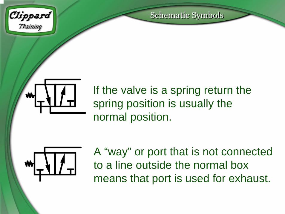
If the valve is a spring return the spring position is usually the normal position.
A “way” or port that is not connected to a line outside the normal box means that port is used for exhaust.

Valve Actuation (shift)Actuators are used to change valve positions
and can be mechanical, pneumatic pilot or electric solenoid.
Mechanical actuators would include springs, push buttons, plungers, levers and cam rollers.
Pneumatic pilots are similar to cylinders and they change valve position with a pressurized air
signal.

Electric solenoids that change valve position by directly moving the valve element are
called direct solenoid.
Electric solenoids that open small pilot valves and allowing pressurized air to move the
valve element are called solenoid controlled pilot operators.

Valve Actuator Symbols
Spring Air Pilot
Push Button Solenoid
Plunger Solenoid Air Pilot
Lever
Cam Roller

Two and three way valves with a spring return are further identified as being
normally closed (non passing) or normally open (passing).
Three way valves can also be referred to as a selector valve, diverter valve, and, as
an “AND” and “NOT”.
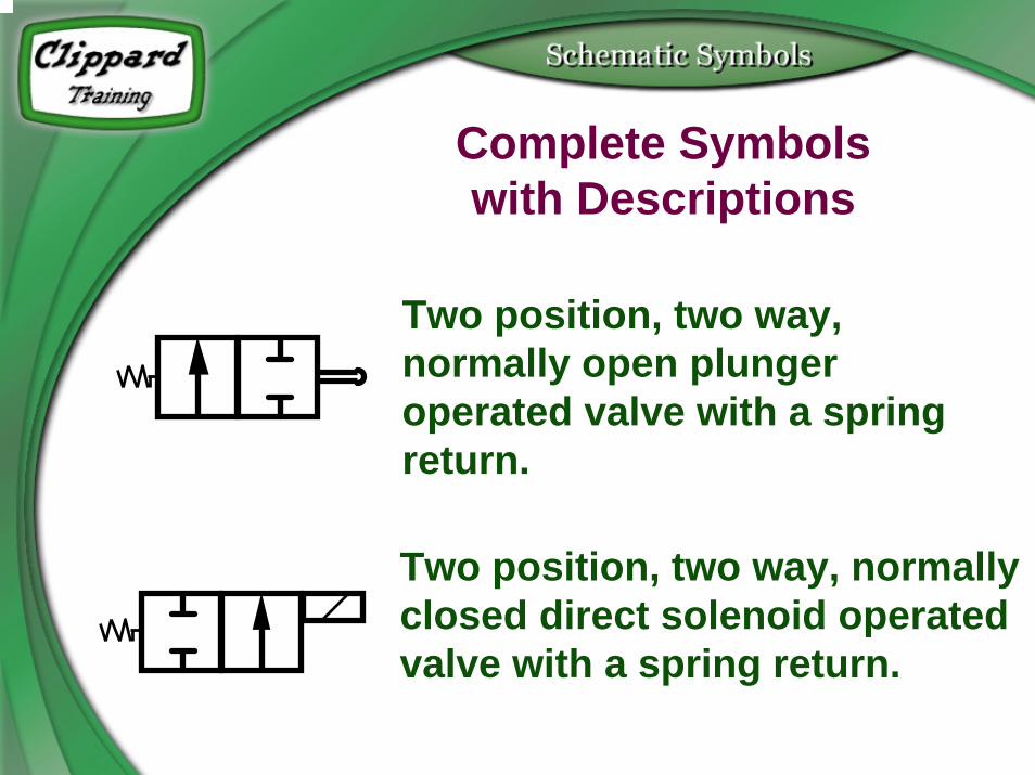
Complete Symbolswith Descriptions
Two position, two way, normally open plunger operated valve with a spring return.
Two position, two way, normally closed direct solenoid operated valve with a spring return.
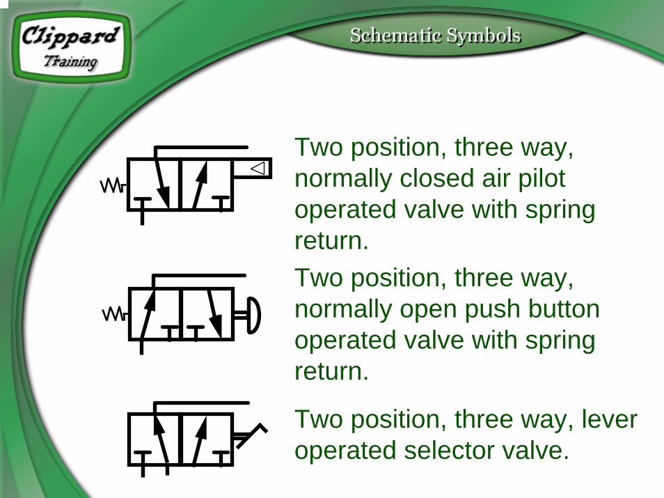
Two position, three way, normally closed air pilot operated valve with spring return.Two position, three way, normally open push button operated valve with spring return.
Two position, three way, lever operated selector valve.
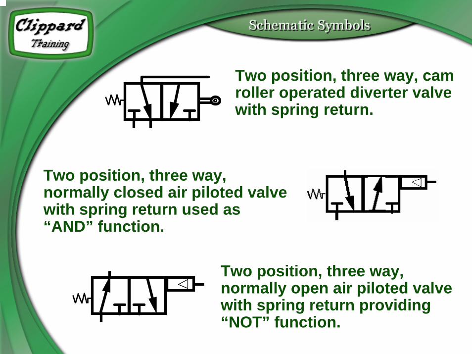
Two position, three way, cam roller operated diverter valve with spring return.
Two position, three way, normally closed air piloted valve with spring return used as “AND” function.
Two position, three way, normally open air piloted valve with spring return providing “NOT” function.

Two position, four way, solenoid air pilot valve with spring return.
Two position, four way, air pilot valve with spring return.

Two position, 5 ported four way, double air pilot.
Three position, 5 ported four way, double air pilot valve spring centered.
ActuatorsActuators perform the work in Fluid Power
Circuits. They are used to clamp, move, rotate, turn and position.
Cylinders are used for linear movements while rotary actuators are used for limited rotational applications and air motors are
used for continuous rotation.

Actuators
Single acting cylinder,load return
Single acting cylinder, spring return
Double acting cylinder

Actuators
Rotary Actuator
Air Motor
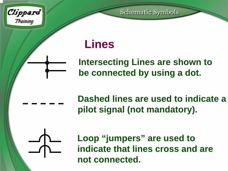
Lines Intersecting Lines are shown to be connected by using a dot.
Dashed lines are used to indicate a pilot signal (not mandatory).
Loop “jumpers” are used to indicate that lines cross and are not connected.
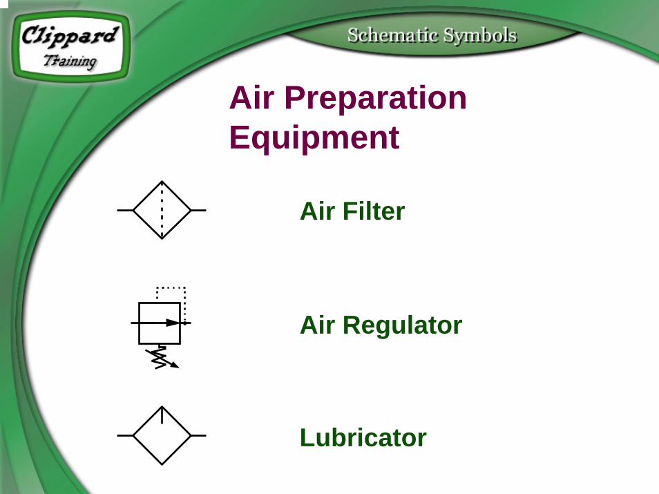
Air PreparationEquipment
Air Filter
Air Regulator
Lubricator

Accessory Valves
Needle Valve
Check Valve
Flow Control Valve

Accessory Valves
Shuttle Valve
Quick Exhaust valve
Pulse Valve (one shot)