Embed Size (px)
Citation preview
Requirements Eng (1998)3:48-65 �9 1998 Springer-Verlag London Limited Requirements
Engineering
Scenario-Based Requirements Analysis Alistair Sutcliffe
Centre for HCI Design, School of Informatics, City University, London, UK
A method for scenario-based requirements engineering is described. The method uses two types of scenario: structure models of" the system context and scripts of system usage. A modelling language is reported for describing scenarios, and heuristics are given to cross- check dependencies between scenario models and the requirements specification. Heuristics are grouped into several anah,tic treatments that investigate correspon- dences between users' goals and system fimctions; input events and system processes to deal with them: system output and its destination in the scenario model, and acceptability anah,sis of system output for different stakehoMetw. The method is i/htstrated with a case study taken from the London Ambulance Service report. The prospects for scenario-based requirements engin- eering and related work are discussed.
Keywords: Analysis heuristics; Domain models; Human error; Requirements engineering; Scenarios; Use-cases; Walk through methods
1. Introduction
In spite of the increasing attention that scenarios have attracted in requirements engineering (RE) [1], few methods have merged to guide the practice of scenario- based requirements analysis or validation. Several dif- ferent interpretations have appeared, ranging from scen- arios as a basis for generating user cases [2], descrip- tions of system usage to help understand socio-
Correspondence and offprhu requests to: Alistair Sutcliffe, Centre tor HCI Design, School of Informatics, City University, Northampton Square, London ECIV 0HB, UK. Email: [email protected]
technical system implications [3], and experience-based narratives for requirements elicitation and validation [4,5]. However, few authors give advice on how to use scenarios in the process of analysis and validation. One of the exceptions is the Inquiry Cycle of Potts [4], which describes scenario scripts of system use with a method for goal-oriented requirements analysis. Dependencies between the events originating in the scenario are validated against the requirements specifi- cation, and the requirements are elaborated to deal with obstacles or problems that prevent successful system operation. Unfortunately, the Inquiry Cycle does not give detailed advice about how scenarios are used to generate questions; furthermore, it leaves open to human judgement how dependencies between system output and users are determined. Nevertheless, the Inquiry Cycle has demonstrated its utility in industrial- scale case studies [6].
This paper builds on the concepts of the Inquiry Cycle with the aim of providing rnore detailed advice about how scenarios can be used in requirements analy- sis and validation. In our previous work we proposed a scenario-based requirements analysis method (SCRAM) that recommended a combination of concept demon- strators, scenarios and design rationale [5,7]. Scenarios described typical user tasks and concept demonstrators portrayed an early design vision of the required system. SCRAM, however, gave only outline guidance for a scenario-based analysis.
Scenarios have been used with many different con- notations. One important distinction is between scen- arios that form part of the specification of the required system, or are derived from it, versus scenarios that are captured from actual experience and do not orig- inate from a system design. The former view has been adopted in user cases in the object-oriented literature [2,8,9], in which a use case embodies a projected vision of user interaction with the designed system. Scenarios are threads of interaction which may occur

Scenario-Based Requirements Analysis 49
through the network of a user case that describes several pathways in user-system interaction. Scenarios of this type have several precedents; for instance, viewpoints in CORE [10] described interaction between an intended system and external agents, as did context diagrams in structured systems analysis [11]. We use scenarios in the second sense, as descriptions taken from reality before a system is implemented, and used to validate the required system. This concords with scenario scripts as advocated by the Inquiry Cycle [4].
Validating requirements by focusing on dependencies between the intended system and its immediate environment has been researched by Jackson [12], who points out that domains impose obligations on a required system. Jackson formalises event dependencies between the system and its environment that are inherent in the laws of physics, e.g. obligations for a required system in avionics and other real-time appli- cations, and events that may arise from human failure, but the causality of such failure is not explicitly ana- lysed and the obligations of systems to users are not addressed. Modelling relationships and dependencies between people and systems has been investigated by Mylopoulos et al. [13] and Chung [14]. Their i* frame- work is composed of strategic dependency and strategic rationale enterprise models which facilitate investi- gation relationships between requirements goals, agents and tasks. The models make no judgement about the system boundary; instead, the framework is applied to a socio-technical system. Although scenarios do not appear in the i* framework, enterprise models may be derived from scenarios of the intended system environ- ment. This research and others in the enterprise model- ling tradition [15,16] suggest some approaches for vali- dating requirements at the social level, but no detailed guidance is given so the practitioner is left with the problem of extracting general lessons from examples. In conclusion, methods are required to unlock the potential of scenario-based RE; furthermore, the relationship between investigation based on examples and models need to be understood more clearly. With this motivation in mind, this paper reports on develop- ment of the second-generation SCRAM method that integrates scenarios with model based requirements analysis.
The paper is organised in three sections. First we introduce scenario-based requirements analysis, a schema for representing scenario-based knowledge, and explain the background to the case study of the London Ambulance service, a well-known system failure caused by poor RE. Section 3 describes a walkthrough method for scenario-based requirements validation that investi- gates both inbound and outbound event dependencies. Each step is illustrated by the case study. Finally, we
discuss related work and future prospects for scenario- based RE.
2. Scenario-Based Requirements Analysis
First it is necessary to define a knowledge represen- tation schema for scenarios. This is a prerequisite for the walkthrough method that analyses the dependencies between the system components and their environment�9 Although we describe the dependency checking in two separate sections, one for inbound and one for out- bound events, in practice analysis of both is inter- leaved.
For our purposes, scenarios are defined as 'facts describing an existing system and its environment including the behaviour of agents and sufficient context information to allow discovery and validation of system requirements'. Scenarios are instances of actual experi- ence with a system captured from users. Since agent's behaviour is a key component in scenarios, we adapt scripts proposed in the Inquiry Cycle [4], i.e., an instant storyline of events describing system operation. To scripts we add further detail of the system environ- ment so the context of activity can be evaluated. Scenario-based models are created to describe the sys- tem environment which can then be investigated for connections and dependencies between the system and its environment. Scenario modelling may appear to be similar to system modelling; indeed the content of a system or environment model depends on where the boundary of the intended system is placed. System boundaries will frequently change during a require- ments investigation, hence we see a single model of the intended system-environment upon which a bound- ary will be eventually imposed. Furthermore, within the model alternative technical system specifications may be explored. When the boundary of the required system becomes fixed, use cases may be constructed to describe interaction between stakeholders and the system, facilitating the migration from requirements analysis described in this paper to object-oriented speci- fications. The method described in this paper is intended to extend and complement the early phases of object-oriented development following use case approach (e.g. UML [17]). The relationship between scenarios and the requirements specification is illus- trated in Fig. 1. Scenarios contain information about operation of the current system and its environment. While scenarios are usually examples of interaction at the instance level, e.g. 'Jane filled in the order form and pressed the enter key to send it to the database', they may also contain contextual information about the

50 A. Sutcliffe
system environment, e.g. 'Jane worked in a busy office; she was frequently interrupted, which made concentrat- ing on order entry difficult'. Scenarios may contain descriptions of activities in manual systems, interaction with legacy systems, descriptions of agents, roles and their organisation settings. The requirements specifi- cation is an artefact that emerges during the RE process evolving from simple lists of functional desiderata to models that constitute a requirements specification. The method described in this paper uses scenarios as test data and validates requirements by investigating the dependencies between events that originate in the environment (i.e., described in the scenario), on requirements specification and system error. In the latter case scenarios are used projector stories of sys- tem use.
Scenarios are captured as text narratives, sketches and informal media. As analysis progresses, informal representations may be replaced by models. The first question is: how far should the modelling endeavour be extended from the system core outwards into the social domain? Ultimately, the whole of society could be modelled, but economics dictate that modelling be restricted to the essential set of facts that are useful in shaping the new system. Modelling is limited by time and available resources; however, the method indicates the extent of modelling by describing facts about the system environment that should be captured for requirements validation. The second question is: what sort of facts should be captured for modelling? To address this point a scenario-based modelling langu- age is proposed to support understanding of new appli- cation domains. Finally, scenarios contain instance information as they describe real-world events that happen to individuals. This raises the problem of how instant level information is related to types and classes and how much instant information is explicitly mod-
elled in scenarios, rather than leaving it as an example- based narrative description.
The method stages for use of scenarios in require- ments discovery and validation are illustrated in Fig. 2. Two types of scenario are proposed: scenario scripts that describe system usage; and scenario structure mod- els containing facts about the system environment.
Fig. 2. Outline of method steps, showing input from scenarios to requirements analysis.
Fig. 1. Scenarios and models of the required system and its environment.
Scenario-Based Requirements Analysis
Structure models capture a broad view of the mode/led domain to support investigation of the relationship between a required system and its environment. Scripts, on the other hand, take a more detailed view of agents' behaviour for dependency analysis.
The first part of the method analyses the user's goals (1) and checks whether they are supported by system functions. This creates a first-cut requirements specifi- cation which describes high-level system processes. The requirements specification is elaborated by investigating dependencies between input events (2) described in the scenario script and requirements func- tions. This identifies requirements to deal with inbound events from users and the system environment of dif- ferent types as well as analysing unexpected events. Inbound events are described in scenarios of interaction between users and the proposed system. This analysis leads to first-cut decisions about the extent of the automation and user-system boundary as the require- ments specification is updated to add functions to deal with different inbound events. System outputs will be motivated by the users' goals in step (1) and described in terms of process and outline content in the require- ments specification. This enables acceptability and impact of system output on users to be assessed, first by specifying the output in more detail in step (3) and then analysing the requirements to support users' tasks in step 4. This is followed by tracing the destination and use of output by different stakeholders and investigating whether the system provides the necessary support for users' work' and does not make any unac- ceptable demands on them (social impact analysis in step 5). Finally, a stakeholder cost-benefit analysis is carried out to complete the prognosis of how people may react to the required system (step 6). The scenario structure model is used to assess the impact of system output and coupling between the technical and social systems. Scenarios may be imaginary stories of use for the new system, or based on real examples. Although the method implies a sequential process in Fig. 2, in practice many of the stages will be inter- leaved as understanding about the system and its environment increases during requirements analysis. Alternative versions of the requirements specification may be produced depending on decisions on the extent of automation, and scenarios created to explain differ- ent versions to users. The method is described in more detail in Section 3, where the sub-sections map to method steps in Fig. 2. Before proceeding to the method it is necessary to define the models used to represent the scenarios.
51
2.1. Scenario Knowledge Representation Schema
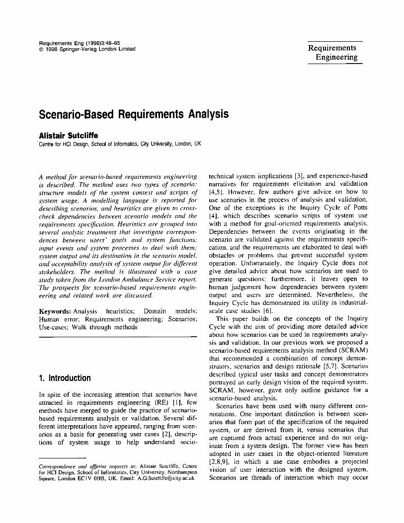
The schema components use semantics that are familiar from software engineering specifications which we have adapted from our previous research [18] for scen- ario modelling. The schema is summarised in Fig. 3.
2.1.1. Objects
Objects are the subject matter of transactions and therefore undergo change. Objects may be physical and subject to laws such as gravity and momentum, or conceptual objects without physical instantiation. Object have properties, i.e. attributes that describe them in quantitative and qualitative terms.
2.1.2. Agents
Agents have properties and methods. Agents are specialisations of objects and carry out activities. Agents can be sub-typed as human or automated agents to describe a required computer system and its users. Agents have roles that describe the allocation of activi- ties or tasks that an agent has assumed responsibility for. Properties describe the agent's knowledge of the domain and task, which is useful in determining an agent's competence to carry out a task and in specify- ing training requirements.
2.1.3. Structure Objects
Structure objects represent visuo-spatial information and physical environmental facts which would not normally appear in data models, e.g. warehouse, library, air corridors in air traffic control. Structure objects model approximations to the real-world entities which must be persistent, have spatial properties and express containment or possession of objects; for
Fig. 3. Schema for scenario modelling expressed as an entity. relationship diagram.

52 A. Sutcliffe
example, a library contains books. Structure objects model physical units such as departments and build- ings; however, logical units of organisation, with no physical manifestation, are modelled as objects or classes.
2.1.4. Resources
Objects, which are necessary for an activity, but are not consumed by it, are described as resources. Resources are a necessary complement; for instance, a ,flight plan is a necessary resource for navigating an aircraft from a start location to its destination.
2.1.5. Goals
Goal states describe a future, required state which the system should satisfy, maintain or, sometimes, avoid. Goals are held by agents and may express requirements that are functional, i.e. implementable in a design, or relate to performance and quality goals which are not immediately implementable as design features. Require- ments are usually expressed linguistically as intentions, aims or objectives. These statements can be refined into more formal expressions of a future goal state which the system should (or should not) attain.
2.1.6. Activities
Activities are processes that achieve a goal. Activities belong to agents and are processes which normally run to completion resulting in state change of objects. In addition, activities model human tasks. Activities can be decomposed into actions organised in procedures with control constructs of sequence, selection and iteration.
2.1.7. Relationships
Relationships model structural, informational and func- tional associations between objects. Three high-level relationship types are distinguished. Generalisation- specialisation models class hierarchy relationships between objects; aggregation describes part-of and compositional associations; and functional relations denote that objects are associated in achieving some system activity. If an association results in state change, it is a functional relationship, otherwise it serves for information access. At a lower-level relationship sub- types are introduced to model further ~iependencies:
Responsibility: models the association between an agent and an activity or goal which it has the duty to
carry out, e.g. <agent, is-responsible-for, goal ] activity>.
Authorit3,: describes the relationship between two agents in which a dominant agent has authority over the behaviour of a subordinate, or ability of an agent to permit another agent to initiate action or consume some resource; e.g. <agent, has-authority-over, agent [ac t iv i ty ] resource]> .
DependenQ,: models the need for an activity to achieve a goal, or for sub-goals to be achieved to enable a subsequent goal to be completed, or the need for a resource or agent to complete an activity, e.g. <goal, depends-on, sub-goal>.
Contribution: this is a specialisation of dependency for non-mandatory relationships when an agent may contribute towards achieving a goal, even though it is not absolutely necessary for completing the goal, e.g. <agent ] resources, contributes-to, activity ] goal>.
Location: is used to describe the location of an object in a point in space with coordinates, or location with respect to a structure object. In this case, an object may be contained within a structure object even though it is not part of it, e.g. <aircraft, is-located-in, air corridor>.
2.1.8. States
States describe properties of objects or agents that persist for a detectable time and are changed by state transitions.
2.1.9. Events
An event is a single point in time when something happens, following Allen's [19] conception of temporal semantics. Events are treated as semaphores which initiate a state transition. For instance, the dispatch of goods from warehouse to customer is triggered by a customer order (a request event).
This completes the knowledge representation schema. In the following section we describe how the schema is used for creating a scenario model. First a scenario structure model is created using the schema to describe the major components in the domain and their activity. Then more detailed descriptions of behaviour and interaction between agents are described and illustrated with user cases and event trace diagrams to integrate with standard OO approaches [17]. These detailed descriptions are referred to as scenario scripts and record the event sequences in real-life examples of system operation. As scenario scripts are collected, more event trace diagrams will be added to document the scenario. However, the structure model should
Scenario-Based Requirements Analysis 53
r'emain reasonably constant, although it may need updating if a script introduces a new agent or activity.
2.2. Modelling Scenarios
At this stage, the case study of the London Ambulance Service, a well-documented failure in RE and system design [20], is introduced. The application is a com- plex, socio-technical system which has a documented requirements specification and material from which scenarios can be constructed. As space precludes an exhaustive analysis of the whole system, we illustrate operation of the method with selected elements of the system.
2.2.1. Case Study Description
The London Ambulance Service (LAS) Computer- Aided Dispatch System was initiated in 1991 as a new computer-aided ambulance dispatch system for London. The intention was to replace a resource-intensive man- ual system with a computerised one that would, in essence, enable one human controller to manage an entire incident from call-taking to the arrival of the ambulance at the incident scene. The implementation in October 1992 encountered many problems and oper- ations reverted to the manual system one month later after a series of well-publicised catastrophic failures.
The London Ambulance Service is a large organis- ation. It had, in 1992, over 2700 staff (operational staff, control assistants, managers, administrators, main- tenance and ancillary). It also had 305 accident and emergency ambulances, 445 patient transport service ambulances, two emergency control vehicles, rapid response units and even one helicopter. Much of its operations are real-time and mission-critical, in that people can die if an ambulance does not arrive in time. It requires information about patients, emergencies, hospitals, road conditions, ambulance locations and calls to function effectively. The system is also both distributed and embedded, in that it relies on much hardware to define the location of ambulances, com- municate with ambulance crews and so on. Indeed, the mobile nature of its operations in London make the system very complex and prone to problems.
The original system had evolved over a considerable period of time. Ambulance crews had considerable knowledge of London as well as emergency conditions, and the control room staff worked as closely knit teams in constant communication with each other to dispatch the most appropriate ambulance to the right accident. The system relied on skilled individuals with
extensive domain knowledge, including the geography of London.
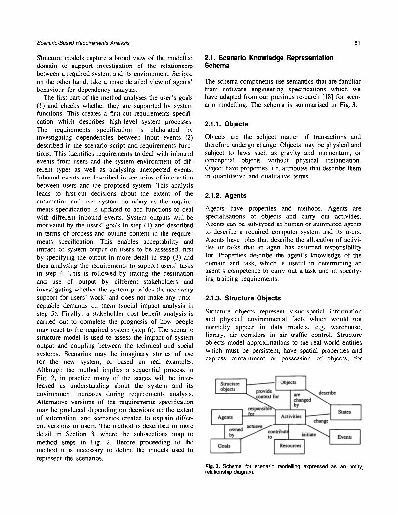
The Computer Aided Dispatching (CAD) system (Fig. 4) had four main functions: call-taking from the public; resource (ambulance) identification; resource (ambulance) mobilisation; and resource (ambulance) management. Call-taking involved telephone operators and control assistants who used local knowledge and a map book to complete an incident form. These incident forms were passed to resource controllers and allocators who allocated resources to calls. The incident report was amended and passed to the dispatcher, who either sent it to the local ambulance station for action or made radio contact with ambulance crews. The ambulance was then dispatched. The new CAD system was intended to automate as much of this process as possible, thus reducing the workload and reliance on control room staff. It included a computer-based gazet- teer of London and a resource proposal system linked to an Automatic Vehicle Location System (AVLS) that tracked the ambulance locations.
Immediately following the system cut-over, the call traffic load increased (but not to exceptional levels). The AVLS could not keep track of the status and location of ambulances. This led to an incorrect datab- ase so that ambulances were not being dispatched
Fig. 4. The Computer Aided Dispatch (CAD) system, showing agents, system functions and communication channels. The orig- inal manual system had these functions but they were distributed over more roles: call takers, resource allocators, dispatchers and radio operators.
54 A. Sutcliffe
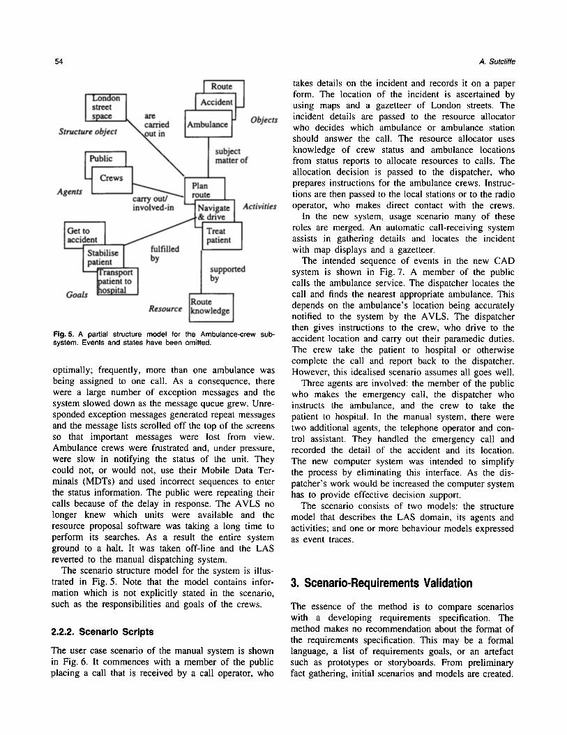
Fig. 5. A partial structure model for the Ambulance-crew sub- system. Events and states have been omitted.
optimally; frequently, more than one ambulance was being assigned to one call. As a consequence, there were a large number of exception messages and the system slowed down as the message queue grew. Unre- sponded exception messages generated repeat messages and the message lists scrolled off the top of the screens so that important messages were lost from view. Ambulance crews were frustrated and, under pressure, were slow in notifying the status of the unit. They could not, or would not, use their Mobile Data Ter- minals (MDTs) and used incorrect sequences to enter the status information. The public were repeating their calls because of the delay in response. The AVLS no longer knew which units were available and the resource proposal software was taking a long time to perform its searches. As a result the entire system ground to a halt. It was taken off-line and the LAS reverted to the manual dispatching system.
The scenario structure model for the system is illus- trated in Fig. 5. Note that the model contains infor- mation which is not explicitly stated in the scenario, such as the responsibilities and goals of the crews.
2.2.2. Scenar io Scr ipts
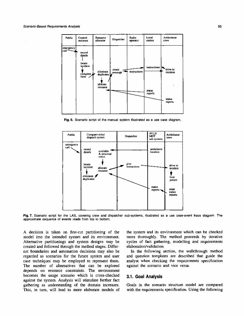
The user case scenario of the manual system is shown in Fig. 6. It commences with a member of the public placing a call that is received by a call operator, who
takes details on the form. The location using maps and a incident details are who decides which
incident and records it on a paper of the incident is ascertained by gazetteer of London streets. The passed to the resource allocator ambulance or ambulance station
should answer the call. The resource allocator uses knowledge of crew status and ambulance locations from status reports to allocate resources to calls. The allocation decision is passed to the dispatcher, who prepares instructions for the ambulance crews. Instruc- tions are then passed to the local stations or to the radio operator, who makes direct contact with the crews.
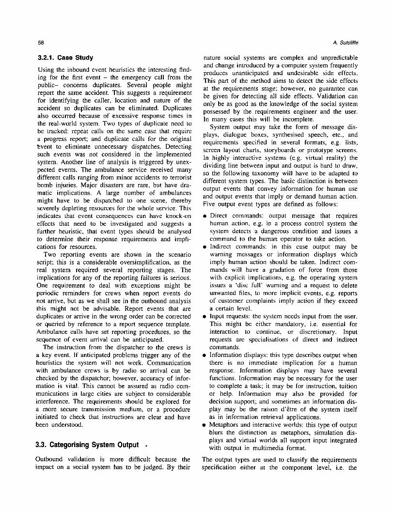
In the new system, usage scenario many of these roles are merged. An automatic call-receiving system assists in gathering details and locates the incident with map displays and a gazetteer.
The intended sequence of events in the new CAD system is shown in Fig. 7. A member of the public calls the ambulance service. The dispatcher locates the call and finds the nearest appropriate ambulance. This depends on the ambulance 's location being accurately notified to the system by the AVLS. The dispatcher then gives instructions to the crew, who drive to the accident location and carry out their paramedic duties. The crew take the patient to hospital or otherwise complete the call and report back to the dispatcher. However, this idealised scenario assumes all goes well.
Three agents are involved: the member of the public who makes the emergency call, the dispatcher who instructs the ambulance, and the crew to take the patient to hospital. In the manual system, there were two additional agents, the telephone operator and con- trol assistant. They handled the emergency call and recorded the detail of the accident and its location. The new computer system was intended to simplify the process by eliminating this interface. As the dis- patcher 's work would be increased the computer system has to provide effective decision support.
The scenario consists of two models: the structure model that describes the LAS domain, its agents and activities; and one or more behaviour models expressed as event traces.
3. Scenario-Requirements Validation
The essence of the method is to compare scenarios with a developing requirements specification. The method makes no recommendation about the format of the requirements specification. This may be a formal language, a list of requirements goals, or an artefact such as prototypes or storyboards. From preliminary fact gathering, initial scenarios and models are created.
Scenario-Based Requirements Analysis 55
Public
emergency call
Control assistant
=" record dltails
locate i;cident
ebmplete.l form /
Resource allocator
eliminate ~" duplicates
all~ocate / resogror
Dispatcher
create
~ message - '~
Radio operator
instructions
Local station
instructions =
status reports
Ambulance crew
'a~'drive to incident
status reports
Fig. 6. Scenario script of the manual system illustrated as a use case diagram.
Public Computer aided AVLS/ Ambulance dispatch system Dispatcher MDT sub systems crew
emergency call"
record details available
& proximal CleWS
locate incident allocate
rCSOUroe
eliminate f duplicates
give instructions
ambulance location
status reports
drive to incident
treat patient
eltt(~' .. status
reports
Fig. 7. Scenario script for the LAS, covering crew and dispatcher sub-systems, illustrated as a use case-event trace diagram. The approximate sequence of events reads from top to bottom.
A decision is taken on first-cut partitioning of the model into the intended system and its environment. Alternative partitionings and system designs may be created and followed through the method stages. Differ- ent boundaries and automation decisions may also be regarded as scenarios for the future system and user case techniques may be employed to represent them. The number of alternatives that can be explored depends on resource constraints. The environment becomes the usage scenario which is cross-checked against the system. Analysis will stimulate further fact gathering as understanding of the domain increases. This, in turn, will lead to more elaborate models of
the system and its environment which can be checked more thoroughly. The method proceeds by iterative cycles of fact gathering, modelling and requirements elaboration/validation.
In the following section, the walkthrough method and question templates are described that guide the analyst when checking the requirements specification against the scenario and vice versa.
3.1. Goal Analysis
Goals in the scenario structure model are compared with the requirements specification. Using the following

56 A. Sutcliffe
heuristics, each user goal in the scenario is cross- checked with functional goals with the requirements specification.
�9 Does the user's goal require computerised support? If so then a functional requirement should be added to the requirements specification; otherwise impli- cations for non-functional requirements should be considered.
�9 Does the goal describe a quality or performance property that the system should achieve? These properties indicate non-functional requirements
�9 (NFR) that may not be directly implemented. NFR goals should be linked with agents and activities that may help to achieve them.
�9 If a goal does not require computerised support, can it be achieved by manual procedures? This points to the need for developing operating procedure man- uals for activities in the social system.
�9 Does the goal require a management decision about resources and responsibilities? Management responsibility goals should be linked to the appropri- ate agent in the scenario model.
�9 Can the scenario goal and its associated activity be fully automated? If it can then transfer the segment of the scenario model to the requirements specifi- cation; if only partial automation is required then further elaboration of the model and the requirements specification is needed.
3.1.1. Case Study
In the LAS system, the users' goals were never explicitly analysed, apart from the aims of senior man- agement; moreover, the failure to investigate all the stakeholders' needs was one of the main contributions to the system failure. Four main stakeholder groups were involved: the public, ambulance crews, dis- patchers and management. The original system was driven by management's goals. We may surmise that the stakeholders' goals were as follows:
Public: to receive prompt response and quick arrival of an ambulance. Ambulance crews: to obtain accurate information about the accident and its location, and helpful instructions for completing the job (e.g. traffic congestion reports); to drive to the accident location as quickly as possible; to give paramedical attention to the causality; to remove the casualty to hospital as quickly and safely as possible. Dispatchers: to determine the location and priority of the accident, to plan dispatch of the nearest, appropriate ambulance to the call; to monitor progress of the call;
and to obtain accurate information on the status of the call and ambulance crews. Managers: to deliver an efficient service and reduce costs; to optimise the use of ambulances and crew resources.
When these goals are compared to activities in the structure model it appears that many goals are sup- ported only by human activities. Planning and schedul- ing is a key activity that depends on several goals, and these goals are held by different stakeholders. Even in this high-level analysis the seeds of conflict are apparent. The automated system appeared to sup- port the dispatchers' goals but, as becomes apparent later in the analysis, this support was inappropriate. Little support was provided for the crews, whereas the system was intended to support management's objec- tives of reducing manpower and improving resource utilisation.
3.2. Investigating Inbound Event Dependencies
A cornerstone of the method is checking dependencies from the environment to the system that commences by tracing the source of all potential input events. Events may originate from two sources:
�9 Agents in the environment, usually people who gen- erate system input.
�9 Objects in the environment that produce naturally occurring events, such as thunderstorms, movement of animals, etc.
Events may have a complex origin in human-machine systems when one agent controls another. For instance, a pilot initiates events in the flight plan of an aircraft by sending a message to the autopilot which causes the aircraft to change direction. In such complex events we prefer to model the human agent as the event originator.
At the top level the scenario is analysed to identify all the event-generating agents and objects. In infor- mation systems most of the events of interest will emanate from human users; in real-time systems many events will originate from the physical world or another system, e.g. an oil refinery will create events communi- cating pressure and temperature changes to the con- trol system.
Using the scenario script, for each inbound event ascertain:
�9 Is there a system function to deal with it? If not, then new functional requirements should be elaborated.
�9 Does the event require the system to attain a goal

Scenario-Based Requirements Analysis 57
state? If so, does a process exist to carry out the necessary change?
�9 Does the event imply that the system should main- tain a goal state? If so, then can the system interpret deviation from that state? Can the system take remedial action to return to the desired state? Answers to this question suggest functional require- ments to monitor normal states and correct devi- ations from the ideal state.
Once the requirements have been established to deal with normal events, exception analysis is undertaken to elaborate system requirements to deal with abnormal event patterns. If the event is created by a human agent then production may not be reliable. Events that emanate from inanimate objects may be more reliable but detecting them may not be. The following questions check for possible permutations that may occur. These may be suggested or ruled out by the scenario; how- ever, the questions can be used to generate further scenario scripts as well as for analysing scripts describ- ing normal behaviour.
�9 What happens if the event doesn ' t arrive? Can the system continue to function? If the event is essential will the system signal a malfunction?
�9 What happens if the event arrives too early or too late? Is the system time-sensitive? Can early events be buffered until processed? If so, how many can be buffered? Can late arriving events be tolerated? If so, can the system halt other tasks and resume on arrival? If not, can a malfunction be reported?
�9 What happens if an event arrives in the wrong order? Is the system sequence dependent? If so, can mal-ordered events be buffered and sorted into an acceptable order?
�9 What happens if a duplicate event arrives? Can the system detect duplicates and, if so, can it eliminate unwanted copies?
�9 What happens if an unexpected event arrives? Can the system deal with unknown input? Can the system interpret extraneous events and report their presence?
�9 What happens if a corrupted event arrives? In this case can the system detect that an event of the correct type has arrived but the contents of the message are damaged? Can the system send a request for the event message to be retransmitted?
The design implications for these dependencies are well known in the software engineering literature. Deal- ing with event permutation requires guarded commands to be designed. The requirements specification can be elaborated with entity life histories which express pat- terns of correct and incorrect events in a sequential order; see Jackson's method [21,22]. As Jackson points out, a filter process can be specified to detect abnormal
events by test probes in a normal input sequence and then take corrective action if an unexpected event is detected. If the dependencies between the scenario and components in the intended system are predictable then validation requirements for mal-formed inputs are eas- ily specified; however, if event arrival is random then requirements are more difficult to elaborate. Three main classes of events imply the different responses by the system:
�9 Known events which can be validated for the order and timing of their arrival. In this case there is a system requirement to detect the event order against an expected life history and then take error-cor- recting action.
�9 Known events which may arrive in any order. The requirements in this case are to check for the plausi- bility of events and provide undo facilities to correct user mistakes or warning messages when events appear to be unusual, e.g. an aircraft descends after leaving an airport.
�9 Unknown events: the system should continue to function correctly so the requirement is for an excep- tion capture procedure; or a reporting mechanism so human operators can investigate exceptional events.
Inbound events imply requirements for processes to trap the input and deal with normal and abnormal patterns. For abnormal patterns, error recovery is neces- sary and in safety critical systems this can become complex, as the system may have to take action to prevent undesired states. This specialisation of require- ments analysis is dealt with in more depth by Sut- cliffe [23].
The last part of inbound event validation is to trace the event of the source. This is important when security is a critical requirement.
Can the source of the event be traced to a specific individual? If so, was the individual authorised to send the event-message? The requirements impli- cations are for logs to identify the message source and individual password protection.
In networked systems the source of an event is often difficult to detect. In these cases an authorisation proto- col may be required so that the origin of the event can be checked. Additional security considerations are whether the event can be intercepted:
�9 Can the event-message be read by anyone else? If the message must be secure then encryption is" required.
58 A. Sutcliffe
3.2.1. Case Study
Using the inbound event heuristics the interesting find- ing for the first event - the emergency call from the public- concerns duplicates. Several people might report the same accident. This suggests a requirement for identifying the caller, location and nature of the accident so duplicates can be eliminated. Duplicates also occurred because of excessive response times in the real-world system. Two types of duplicate need to be tracked: repeat calls on the same case that require a progress report; and duplicate calls for the original "~vent to eliminate unnecessary dispatches. Detecting such events was not considered in the implemented system. Another line of analysis is triggered by unex- pected events. The ambulance service received many different calls ranging from minor accidents to terrorist bomb injuries. Major disasters are rare, but have dra- matic implications. A large number of ambulances might have to be dispatched to one scene, thereby severely depleting resources for the whole service. This indicates that event consequences can have knock-on effects that need to be investigated and suggests a further heuristic, that event types should be analysed to determine their response requirements and impli- cations for resources.
Two reporting events are shown in the scenario script; this is a considerable oversimplification, as the real system required several reporting stages. The implications for any of the reporting failures is serious. One requirement to deal with exceptions might be periodic reminders for crews when report events do not arrive, but as we shall see in the outbound analysis this might not be advisable. Report events that are duplicates or arrive in the wrong order can be corrected or queried by reference to a report sequence template. Ambulance calls have set reporting procedures, so the sequence of event arrival can be anticipated.
The instruction from the dispatcher to the crews is a key event. If anticipated problems trigger any of the heuristics the system will not work. Communication with ambulance crews is by radio so arrival can be checked by the dispatcher; however, accuracy of infor- mation is vital. This cannot be assured as radio com- munications in large cities are subject to considerable interference. The requirements should be explored for a more secure transmission medium, or a procedure initiated to check that instructions are clear and have been understood.
3.3. Categorising System Output .
Outbound validation is more difficult because the impact on a social system has to be judged. By their
nature social systems are complex and unpredictable and change introduced by a computer system frequently produces unanticipated and undesirable side effects. This part of the method aims to detect the side effects at the requirements stage; however, no guarantee can be given for detecting all side effects. Validation can only be as good as the knowledge of the social system possessed by the requirements engineer and the user. In many cases this will be incomplete.
System output may take the form of message dis- plays, dialogue boxes, synthesised speech, etc., and requirements specified in several formats, e.g. lists, screen layout charts, storyboards or prototype screens. In highly interactive systems (e.g. virtual reality) the dividing line between input and output is hard to draw, so the following taxonomy will have to be adapted to different system types. The basic distinction is between output events that convey information for human use and output events that imply or demand human action. Five output event types are defined as follows:
�9 Direct commands: output message that requires human action, e.g. in a process control system the system detects a dangerous condition and issues a command to the human operator to take action.
�9 Indirect commands: in this case output may be warning messages or information displays which imply human action should be taken. Indirect com- mands will have a gradation of force from those with explicit implications, e.g. the operating system issues a 'disc full' warning and a request to delete unwanted files, to more implicit events, e.g. reports of customer complaints imply action if they exceed a certain level.
�9 Input requests: the system needs input from the user. This might be either mandatory, i.e. essential for interaction to continue, or discretionary. Input requests are specialisations of direct and indirect commands.
�9 Information displays: this type describes output when there is no immediate implication for a human response. Information displays may have several functions. Information may be necessary for the user to complete a task; it may be for instruction, tuition or help. Information may also be provided for decision support; and sometimes an information dis- play may be the raison d'&re of the system itself as in information retrieval applications.
�9 Metaphors and interactive worlds: this type of output blurs the distinction as metaphors, simulation dis- plays and virtual worlds all support input integrated with output in multimedia format.
The output types are used to classify the requirements specification either at the component level, i.e. the

Scenario-Based Requirements Analysis 59
system will produce output of type x from sub-system y; alternatively, output can be classified at the event level when the requirements specification becomes more detailed.
3.4. Output Requirements Analysis
This is driven from both the requirements specification and the scenario. First the scenario and requirements specification are cross-referenced to ensure output is generated when it is needed. Steps in the user's task that imply an information need are identified in the scenario; so if a user needs information at a particular point in the scenario script does a system output function exist to provide it? Using the requirements specification and the scenario script, the following checklist is used to help analyse possible user needs.
�9 Using the requirements specification, for each component that produces output, is there a corre- sponding user requirement for information in the scenario?
�9 Does a user require information at a scenario stage and is the information produced when it will be needed? The coupling between system output and the user task will depend on the application type. In safety-critical systems synchronisation should be precise.
�9 Does the user require information for decision sup- port? This points to output requirements when the system should provide information to help the user's decision making or provide instruction for carrying out the task.
�9 Is the user's goal in the scenario information seek- ing? This points out information retrieval require- ments, which may characterise the whole application, or may be embedded within other tasks.
The questions help to identify the information require- ment dependencies between the users and the system, and in doing so, help to assign output types. A further question focuses attention on how appropriate the out- put information is for the user's task:
�9 Is the information content of the system output appropriate for the user's task or goal? The answer to this question may require a detailed task analysis and is beyond the scope of this paper; however, more detail can be found in the Task-Related Infor- mation Analysis Method [23].
Tracing output to the recipient agent is important when security is required. The destination of system output is assessed using the following questions:
�9 Who should receive the output information? If circu- lation of output should be restricted, functions are required to track the destination of output, obtain certification that it arrives at a correct destination, and possibly prevents unauthorised access during delivery by encryption.
�9 What happens if the wrong person receives the output? If the distribution of messages cannot be guaranteed, yet the destination is important, then encryption should be considered. Another possible requirement is for an audit trail to log who acquired the output.
�9 What happens if the output gets lost? Is the output message critical to the functioning of the whole, socio-technical system? Answers to this question imply requirements for logging message arrival and the ability to request re-sends if the original output does not arrive. The ability to detect lost messages within a time period (e.g. timestamp) and to identify individual messages via a unique code should be considered.
�9 What happens if the output arrives too late or too early? This question is important when accuracy is vital. Out-of-date information may be useless, while information that arrives too early may have missed key updates. Answers to this question imply require- ments to ensure timely arrival, e.g. network prioritis- ation, timestamp priority; or controlling database update integrity for reporting information.
�9 What happens if the output arrives in the wrong order? If output order has to be geared to a set sequence, then functions to ensure the sequential integrity of the output are required, e.g. by num- bering messages or designing a protocol to acknowl- edge receipt of one message before the next is sent.
�9 What happens if the information is inappropriate or incorrect? This question focuses on the link between the system output and the user's task. The answer may depend on a thorough task information analysis [23]; however, cross-checking with the scenario may suffice to generate an answer. In some cases the user's task may not be predictable, hence require- ments for a clarification dialogue or configurable information displays are indicated.
3.4.1. Case Study
The output from the LAS-CAD system contained direct commands from the dispatcher to the crews and manda- tory input requests for the crews to report their location and status. Information displays were critical for the dispatcher. The gazetteer display was supposed to s h o w the locations of calls and ambulances overlaid on a
60 A. Sutcliffe
map of London. The schedule proposer displayed allo- cation lists of crews to calls.
Tracing the system output reveals some discrepancies between the stakeholders' information needs and the system output. For instance, the crews needed infor- mation on traffic congestion and roadworks, but this was not provided by the system. Indeed the crews had only indirect contact with the system output via the dispatcher. The information displays should have been adequate for supporting the dispatchers' decisions, but most of their decision making had been usurped by ,the call allocation proposer. As the responsibility for the crew allocation decision was no longer clear, the dispatchers became frustrated. This was exacerbated by the inaccurate information which prevented them from taking decisions themselves.
Even if the information were accurate, the output display could have been improved by providing better information on possible routes and projected journey times. Often the closest ambulance to the accident location might not be the first to arrive because of one-way streets and roadworks. This information was not provided to dispatchers or crews, even though it was readily available from local radio and police reports.
Applying the outbound event heuristics points to potential problems in tracking system output to the appropriate agents. Instructions from dispatchers might be received by the incorrect crew, so a crew identifi- cation check is necessary. This existed in the manual system. More seriously, instructions to crews can be overheard by the general public and this can lead to undesirable consequences, such as voyeurs causing congestion at major accidents. Secure communications should be considered. As messages can get lost or arrive in the wrong order, a message recording log is needed to help dispatchers trace call progress and diagnose miscommunication problems. Furthermore, messages could be replayed from the log to avoid composing them again.
The effect of incorrect output for the dispatchers was one of the prime causes of system failure. Because accurate information is vital and the possibility of late or lost reporting events cannot be ruled out, a require- ment for cross-checking accuracy needs should have been investigated. This could be implemented by a simple instruction that dispatchers make their under- standing of the crew's location explicit in the call allocation instructions. Any deviation should be detected by the crew and corrected. Error tolerances for inaccurate information and incorrect events should be studied to establish their impact of performance of the user tasks. If the dispatcher can tolerate, say, 1%
inaccurate events without a performance degradation then correction protocols may not be necessary.
3.5. Social Impact Analysis
It should be stated at the outset that this is a difficult task to achieve as success depends on three unknowns:
(a) accurate social theories that predict human behav- iour in response to computer systems:
(b) sufficient knowledge of a particular social system to make predictions using (1);
(c) a stable system environment so that predictions made by (1) using (2) remain valid while the system is being constructed and implemented.
Given that the above three sources of knowledge are not complete, and some would contend cannot be complete, judgement of impact in the social domain must be tentative. Nevertheless, some guidance can be given which may uncover a few potential problems.
Investigation begins by assessing the coupling between the social and technical systems. The system output commands, both direct or indirect, are counted. The more commands there are, the closer the coupling between the social and technical systems will be. Close coupling increases dependencies and makes the whole socio-technical system prone to failure. General design advice is to divide the system into autonomous sub- systems to reduce coupling. Closely coupled human computer systems should be reviewed to either change the design for more automation (computer autonomy) or increase human control and design the computer system for an advisory rather than a controlling role.
The style of coupling in socio-technical systems has implications for the organisational culture. In hier- archical organisations, lines of authority are clear and power relationships defined by the structure. Close coupling may be possible in hierarchical organisations, although such systems may be brittle and prone to failure if the social environment changes. Networked organisations have loose coupling, so the technical systems in such organisations should reflect this.
The scenario structure model is elaborated to propose different technical system solutions and consequently different system boundaries. The implications of people's reactions to computer systems may vary widely according to where the boundary is drawn. This involves partitioning tasks/activities between people and computers. Heuristics to guide these judgements have been given by several authors [24-26]. Some impact heuristics to bear in mind at the requirements stage are as follows:
1. Excessive automation diminishes human responsi-

Scenario-Based Requirements Analysis 61
bility. This may in turn have an adverse impact on motivation.
2. Excessive automation diminishes human awareness of the whole system; this reduces the user's capacity to respond to abnormal events. The dangers of this in safety critical systems are pointed out by Leveson [27].
3. Automation which leaves users with menial, unde- manding tasks will increase boredom, lower motiv- ation and lead to more errors.
4. Automation with closely coupled interaction imposes new work practices on people. This may cause them to reject the system as it constrains human activity in an unnatural manner.
5. Coupling between users and automated systems should be sensitive to the users' skills and knowl- edge. If the users have to take decisions imposed on them by the computer system, then they should be given the necessary training.
6. Care should be exercised to ensure that introduction of the computer system does not alter responsi- bilities and power relationships between people. Although new computer systems invariably alter responsibilities, these changes should be assessed and ameliorated where possible. Furthermore, the changes should be explained and justified to the u s e r s .
Once the technical system boundary has been estab- lished, power and authority relations can be traced to check whether the system output will fulfil users' goals, and that authority relationships are clear and do not contradict each other (e.g. two agents in charge of one activity, conflict in authority). Information output may have unexpected consequences. The effect of providing information for an agent should be assessed to see if it will alter that person's role or potential power. For instance, providing one person with another person's work schedule gives an opportunity for mischief, e.g. the first agent may tell the second to do something in the wrong order. Such problems are difficult to detect a priori, and a better defence is to have well-motivated, well-trained staff who are unlikely to create misde- meanours. However, in financial applications where security is paramount, asking whether information is likely to be misused by a receiving agent is advisable. Power relations may be implicit in the form of incen- tives and monitoring results rather than by direct reporting. The scenario structure model is used to assess the impact of commands by tracing the output event to its destination in the social system and asking the following questions:
�9 Does system output trigger an activity that a human
agent is responsible for? This indicates a direct com- mand.
�9 Is the system output a necessary input for human activity or does it imply the need for decision making? This suggests an indirect command.
�9 Is system output a helpful, although not strictly necessary, resource for completion of a human activity? This indicates an indirect dependency.
Once system commands have been identified their impact can be assessed by tracing the output to the recipient agents and their goals, responsibilities, roles and authority in the social domain. The following questions point out potential problems and guide the analyst towards issues that may need to be investigated.
For each system output-command, trace the agents which will be involved to assess: if the appropriate person being asked to comply with the command. The answer can be found by:
(a) Inspecting the agent's properties to determine whether they have the necessary skills or knowl- edge to undertake the task or take the decision. If they do not, then there are implications for personnel selection or training;
(b) Inspecting the role and tasks the agent is respon- sible for. If the command is being directed to the wrong person then the social system should be changed;
(c) Determining whether the person can respond in time and in an appropriate manner. Investigate the time demands for decision making or carrying out tasks and checking the user's training and role.
The next step is to establish whether the users are likely to comply with system commands. Possible reasons why they may not are lack of motivation, or that they see the command as an imposition on their responsibilities. Pointers to answers may be found by tracing the responsibility and authority relationships of the agent to ascertain the following:
(a) Does the command create a clash in responsi- bilities, e.g. the system asks an agent to take a decision which exceeds their responsibility?
(b) Does the command infringe the user's authority, e.g. the system requires the user to take a decision at the wrong time or takes the decision for them?
(c) Does the command alter the power relationships between human agents, e.g. the command dimin- ishes one person's authority and increases another's?
A complete investigation of these questions goes beyond requirements analysis into socio-technical sys- tem design.
62 A. Sutcliffe
3.6. Stakeholder Analysis
Finally, a stakeholder cost-benefit analysis can help to summarise the previous investigations and highlight potential reactions of personnel to introduction of the new system. This technique assesses the impact of system design on different users or stakeholder groups. The analysis can be repeated on alternative system designs to assess trade-offs for various stakeholders. Each stakeholder group is assessed against the follow- ing questions:
"e Will the new system de-skill their job? Excessive automation is often the culprit.
�9 Could the new system threaten their job security? �9 Will their responsibilities be diminished by the new
system? This may be caused by automating part of a stakeholder's job or redistributing responsibilities in the social system.
�9 Will the system adversely effect working practices? This may have several causes, such as excessive coupling which directs human operators and allows no flexibility; removing the ability to take decisions and autonomous action; change in authority requiring clearance before action can be taken; and not provid- ing sufficient information to complete a task.
The potential benefits of enhanced responsibility, more
stimulating job descriptions, opportunities for self- advancement and promotion should be offset against these downsides. If any stakeholder group has a pre- ponderance of downsides then their motivation and willingness to cooperate with the new system will be decreased. This can lead to more mistakes, non- compliance with responsibilities and duties and ulti- mately sabotage. The answers may be gathered by interviewing stakeholders directly for their opinions or by judgement of independent experts. Cost-benefit analysis may be conducted at the sub-system or compo- nent level if necessary.
3.6.1. Case Study
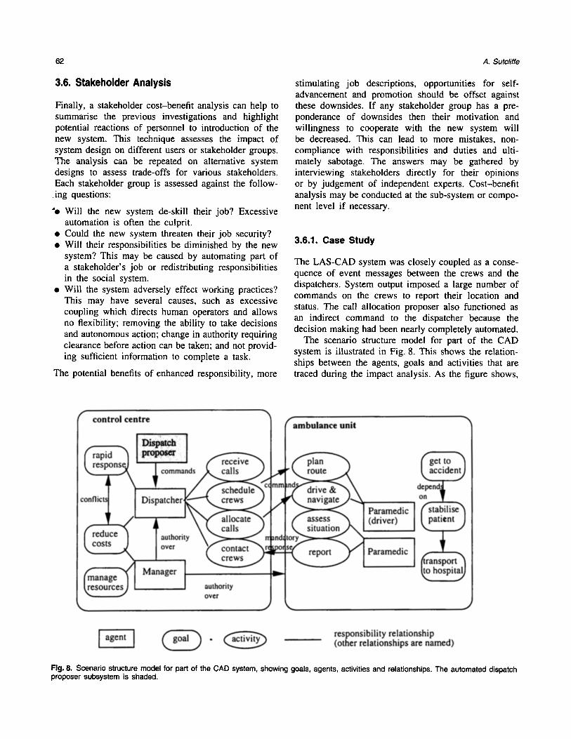
The LAS-CAD system was closely coupled as a conse- quence of event messages between the crews and the dispatchers. System output imposed a large number of commands on the crews to report their location and status. The call allocation proposer also functioned as an indirect command to the dispatcher because the decision making had been nearly completely automated.
The scenario structure model for part of the CAD system is illustrated in Fig. 8. This shows the relation- ships between the agents, goals and activities that are traced during the impact analysis. As the figure shows,
Fig. 8. Scenario structure model for part of the CAD system, showing goals, agents, activities and relationships. The automated dispatch proposer subsystem is shaded.
Scenario-Based Requirements Analysis 63
the dispatchers' role has become complex, with many responsibilities.
When the costs and benefits for each group of stakeholders are analysed it can be seen that manage- ment were the only significant gainers (see Table 1). Both the crews and dispatchers suffered from fears of deskilling and possible loss of their jobs as a result of the system. The system also imposed more demands on the crews than the manual system. It is not surpris- ing that the crews did not comply with the reporting procedures and the dispatchers became demoralised and frustrated.
Inspecting the agents' roles and tasks suggests that the manual system had an appropriate allocation of tasks to agents. The dispatchers and crews both had extensive domain knowledge that they used to carry out tasks. This might present a problem for new per- sonnel, so training had to be thorough. The call allo- cation proposer infringed the dispatchers' decision- making authority as it never had accurate information for planning. Even if the computer system had accurate information to function competently there are good social reasons for not completely automating this func- tion. One of them is the need to maintain user knowl- edge for flexible responses. A fully automated system will deskill dispatchers. If people do not actively take decisions they rapidly deny responsibility for those decisions. When a disaster occurs they may have lost vital domain knowledge to enable them to plan a response to an event that no automated scheduler is designed to deal with. Furthermore, the dispatcher's response may be delayed by the tacit assumption that the automated system is responsible and therefore can cope. The impact heuristics point to an insensitivity in design of the system automation that deskilled the crews and misallocated power and responsibility relationships by assuming the computer system could do too much. History proved that allocation of a decision-making role to the unproven computer system was a serious mistake.
Table 1. Stakeholder analysis for the CAD system
Stakeholders Job Responsi- Control Workload security bility
Managers -H- ++ Supervisors + + + Dispatchers - - - + Ambulance c rew- -
4. Discussion
Retrospective case studies inevitably suffer from the benefit of hindsight. It is not clear what the relative contribution of the method and its human user were to the recommendations produced by the analysis. The LAS inquest report dwells on failures in the social domains such as the failure to consult the ambulance crews and the problems of deskilling the dispatchers; however, we have uncovered a wealth of problems that are not mentioned in the report, so we may make some modest claims for effectiveness of the method. Moreover, we may hypothesise that the method has uncovered problems which are still inherent in the current system. The inquiry report blamed management for an inept approach to system development and ascribes the major causes of failure to hardware and system integration issues, such as communications fail- ure between the CAD and AVLS systems, poor software testing and inadequate preparation for system cut-over. We contend that had the developers corrected all these mistakes, there is still a very good chance of failure because of poor requirements analysis in the social domain.
Parts of the scenario-based method reported in this paper are related to the enterprise modelling approach of Mylopoulos et al. [13] and Chung [14]. They create models of the system and its immediate environment using similar semantics. Their strategic dependency and rationale model allow tracing of dependencies between agents, the goals and tasks with limited reasoning to identify trade-offs between functional requirements and non-functional requirements (referred to as soft goals). However, the i* enterprise modelling method does not give advice about creating enterprise models, nor does it contain detailed event dependency analysis such as we have reported.
Dependencies between systems and their environ- ment have been analysed in detail by Jackson and Zave [28], who point out that input events impose obligations on a required system. They propose a for- malism for modelling such dependencies. Formal mod- elling is applicable to the class of system they implicitly analyse, e.g. real-time and safety-critical applications, but it is less clear how such models can deal with the uncertainties of human behaviour. Models of users' goals and their operationalisation in system requirements can be described in the KAOS language [29], which enables behavioural requirements and con- straints to be formally specified; however, KAOS does not use scenarios as test data for requirement vali- dation. We believe our scenario-based approach is more appropriate to deal with uncertainty caused by human behaviour as it focuses on eliciting requirements for
64 A. Sutcliffe
dialogue and system function to repair problems caused by unreliable human behaviour.
So far, the method has not dealt with non-functional requirements. Scenarios can capture the necessary cri- teria which would have to be expressed in quantifiable terms, for instance by the Goals-Quality-Metric approach [30], or in a similar manner by Boehm's [31] win-win analysis. The dependency checking pro- posed in the paper lends itself to assessing some non- functional requirements. For instance, each inbound/outbound event that involves a human agent will be mediated by a user interface. Usability criteria could be attached to these dependencies, while usability guidelines provide the suggestions for how to satisfy this non-functional requirement (see ISO 9241, parts 10, 12, 13, 16, 17) [32]. Performance requirements could be assessed by checking the volume and temporal distribution of events against system requirements, while security as a non-functional requirement has been partially dealt with in the heuristics in this paper. Elaborating the scenario-based approach to cover non- functional requirements is part of our ongoing research.
Scenarios have been used for assessing the impact of technical systems by several authors [1,3,5]. How- ever, these reports give little prescriptive guidance for analysis, so the practitioner is left with examples and case studies from which general lessons have to be extracted. The ORDIT method [16] gives limited heu- ristics that advise checking agent role allocations, but these fall far short of the comprehensive guidance we have proposed. A more comprehensive enterprise- modelling schema is proposed by Rummier and Brache [33] for analysis of business processes according to critical success factors. Our approach has the potential to bridge the gap between business modelling and RE via further elaboration of the social impact analysis.
In many senses the method we have proposed does not contain radically new concepts; instead its strength lies in integration of previous ideas. We have brought concepts from safety-critical system assessment [34,35] to bear on requirements analysis, and integrated these with scenario-based approaches to RE. We acknowl- edge the heritage of the Inquiry Cycle [4]; however, this paper has reported a walkthrough method and a wealth of heuristics that give more comprehensive guidance to solving RE problems. Stakeholder analysis is another influence which has been extensively rese- arched [36], but bringing it together with social impact analysis adds further value because the reasons for stakeholders' opinions can be made explicit by scenario modelling. Specification of a requirements analysis pro- cess for socio-technical system implication is a novel contribution where we have broken ground beyond the previous informal analyses [3,15]. While some may
contend that formalising analytic heuristics cannot cap- ture the diversity of problems in social domains, we answer that some heuristics are better than none and point out that the method is incremental and grows by experience. Failure to formalise knowledge about social implications can only hinder RE.
One problem with an eclectic approach is that it builds a baroque method, which may seem to be unwieldy. Practitioners invariably want 'quick and dirty' methods [37]. Our approach does not preclude adoption of lean methods. Scenario-based analysis can be partitioned into different layers of complexity and developed into variants of the method to suit systems with varying levels of complexity. Tool support is also a necessary component of method success. Accordingly we will develop intelligent tools that embed the heuris- tics as a requirements engineer's guide. A report of an early prototype is given in Minocha et al. [38], which guides the analyst through an agenda of questions and provides suggestions for developing requirements.
In spite of the advances that scenario-based RE may offer, we have still to demonstrate its effectiveness in practice. There is evidence that the approach is effec- tive in empirical studies of earlier versions of the method which did use scenarios but without the heuris- tics [5]. Further validation with industrial case studies is part of our research agenda. Also we will improve the social impact analysis, where we have only just begun to address the complexities of understanding what might go wrong when computer systems are introduced into the social domain.
Acknowledgements. The author would like to thank members of the City CREWS team for comments on earlier drafts of this paper. This research was partially supported by the El_! long-term research project CREWS (Cooperative Require- ments Engineering With Scenarios), partners RWTH-Aachen (project coordinator), City University, London, University of Paris I, FUNDP and University of Namur.
References
I. Carroll JM. The scenario perspective on system develop- ment. In: Carroll JM (ed). Scenario-based design: envisioning work and technology in system development. Wiley, New York, 1995
2. Jacobson I, Christerson M, Jonsson P, Overgaard G. Object oriented software engineering: a use case driven approach. Addison-Wesley, Reading, MA, 1992
3. Kyng M. Creating contexts for design. In: Carroll JM (ed). Scenario-based design: envisioning work and tech- nology in system development. Wiley, New York, 1995, pp 85-108
4. Potts C, Takahashi K, Anton A. Inquiry based require- ments analysis. IEEE Software 1994;March:21-32
Scenario-Based Requirements Analysis 65
5. Sutcliffe AG. A technique combination approach to requirements engineering. In: Proceedings of the 3rd international symposium on requirements engineering, Anapolis, January 1997. IEEE Computer Society Press, Los Alamitos, CA, 1997
6. Potts C, Takahashi K, Smith J, Ora K. An evaluation of inquiry based requirements analysis for an Internet ser- vice. In: Zave P, Harrison MD (eds). Proceedings of RE "95: Second international symposium on requirements engineering. IEEE Computer Society Press, Washington, DC, 1995, pp 27-34
7. Sutcliffe AG. Requirements rationales: integrating approaches to requirements analysis. In: Olson GM, Schuon S (eds). Proceedings of designing interactive systems, DIS '95. ACM Press, New York, 1995, pp 33--42
8. Graham I. Task scripts, use cases and scenarios in object- oriented analysis. Object-Oriented Systems 1996;3: 123-142
9. Cockburn A. Structuring use cases with goals. http://members.aol.com/acockburn/papers/usecase.htm
10. Mullery GP, CORE: a method for controlled requirements expression. In: Thayer RH, Dorfman M (eds). Systems and software requirements engineering. IEEE Computer Society Press, Los Alamitos, 1987. pp 304-131
II. EE Yourdon. Modern structured analysis. Prentice-Hall, Englewood Cliffs, NJ, 1989
12. Jackson M. Software requirements and specifications. Addison-Wesley. Reading, MA, 1995
13. Mylopoulos J, Chung L, Nixon B. Representing and using non-functional requirements: a process-oriented approach. IEEE Trans Software Eng 1992;18(6):483--497
14. Chung L. Representing and using non-functional require- ments: a process-oriented approach. Department of Com- puter Science, University of Toronto, 1993
15. Eason, KD, Harker, SD, Olphert, CW. Representing socio-technical system options in the development of new forms of work organization. Eur J Work Organ Psychol 1996;5(3):399-420
16. Harker SDP, Eason KD, Dobson JE. The change and evolution of requirements as a challenge to the practice of software engineering. In: 1EEE symposium on require- ments engineering, RE '93, San Diego, CA. IEEE Com- puter Society Press, Los Alamitos, CA, 1993, pp 266-272
17. Rational Corporation. UML: unified modelling language. Rational Corp., Boulder, CO, 1997
18. Maiden NAM, Sutcliffe AG. Requirements critiquing using domain abstractions. In: Siddiqi J(ed). Proceedings of the first international conference on requirements engineering. IEEE Computer Society Press, Los Alamitos, CA, 1994, pp 184-193
19. Allen J. A common sense theory of time. In: Proceedings
of the international joint conference on artificial intelli- gence, 1985
20. HMSO. Report of the Inquiry into the London Ambulance Service. HMSO, London, 1993
21. Jackson MA. System development. Prentice-Hall, Engle- wood Cliffs, NJ, 1983
22. Sutcliffe AG. Jackson system development. Prentice- Hall, 1988
23. Sutcliffe AG. Task related information analysis, Int Hum Comput Studies 1997;47:pp 223-257
24. Bailey, RW. Human performance engineering. Prentice- Hall, Englewood Cliffs, NJ, 1982
25. Shneiderman B. Designing.the user system interface, 3rd edn, Morgan Kaufmann, San Francisco, 1997
26. Sutcliffe, AG. Human computer interface design, 2nd edn. Macmillan, London, 1994
27. Leveson N. Safeware: system safety and computers. Addison-Wesley, Reading, MA, 1995
28. Jackson M, Zave P. Domain descriptions. In: IEEE sym- posium on requirements engineering. IEEE Computer Society Press, Los Alamitos, CA, 1993, pp 56-64
29. van Lamsweerde A, Darimont R, Massonet Ph. Goal directed elaboration of requirements for a meeting sched- uler: problems and lessons learnt. In: Harrison MD, Zave P (eds). Proceedings of RE-95, IEEE international symposium on requirements engineering, York, UK. IEEE Computer Society Press, Los Alamitos, CA, 1995
30. Basili VR, Rombach HD, The TAME project: towards improvement-oriented software environments. IEEE Trans Software Eng 1988;14(6):758-773
31. Boehm B, In H. Identifying quality-requirement conflicts. IEEE Software 1996;March:25-35
32. ISO 9241. Ergonomic requirements for office systems: visual display terminals. Parts 10, 11,16, International standards, parts I-9, 12-15, 17. draft standards. Inter- national Standards Organization, Switzerland, available from national standards organisations
33. Rummier GA, Brache AP. Improving performance: how to manage the white space on the organization chart. Jossey-Bass. San Francisco, 1995
34. Hollnagel E. Human reliability analysis: context and con- trol. Academic Press, London, 1993
35. Reason JT. Human error. Cambridge University Press, Cambridge, UK, 1990
36. Macaulay L. Requirements engineering. Springer-Verlag, Berlin, 1996
37. Sommerville 1, Sawyer P. Requirements engineering: a good practice guide. Wiley, New York, 1997
38. Minocha S, Maiden N, Ryan M, Manning K. A cooperat- ive scenario-based approach to acquisition and validation of system requirements: how exceptions can help. In: Proceedings of the Glasgow safety critical system engin- eering workshop, University of Glagow, 1997