Embed Size (px)
Citation preview

SCALING-UP A REACTIVE EXTRUSION OPERATION
Estanislao Ortíz-Rodríguez
andand
Costas Tzoganakis
6/4/2008 IPR Annual Symposium 1
IPR 20
08

Scale-up calculations for reactive extrusion operations
Outline
BackgroundProblem DescriptionResultsConclusionsFuture WorkFuture Work
6/4/2008 IPR Annual Symposium 2
IPR 20
08

Background Problem description Future workResults Conclusions
(a)
Figure 1Figure 1. Modular configuration in a CSCO extruder. Modular configuration in a CSCO extruder(b)
6/4/2008 IPR Annual Symposium 3
gg gg(data (data Leistritz®).®).
IPR 20
08

Background Problem description Future workResults Conclusions
REX d liREX modeling.
- Conservation of mass, momentum and energy equations aswell as the reaction kinetics equations need to be solved.
- One-dimensional (1D) and three-dimensional (3D) models canb d i l hbe used to simulate the system.
- 1D models: geometrical and flow simplifications are used.Th d l i ld l f i tThese models yield average values of processing parametersalong the extruder, from hopper to die.
3D models are less simplified than 1D models- 3D models are less simplified than 1D models.Conventionally, only fully filled sections of the extruder aresimulated in 3D modeling.
6/4/2008 IPR Annual Symposium 4
IPR 20
08

Background Problem description Future workResults Conclusions
(a) (b)
[After Michaeli et al., 1995] [After Vergnes et al., 1998]
Figure 2. Simplified flow geometries used in 1D modeling. a) Curved channels. b) “C-shaped” chambers.
6/4/2008 IPR Annual Symposium 5
g ) ) pIP
R 2008

Background Problem description Future workResults Conclusions
S li l i Equations 2Scaling-up relations- Variables are scaled-up by a
power of the diameter ratio ( l i d )
Equations 2. -Conventional scale-up approach for non-reactive systems(scale-up index). systems.
dDD 1 D[2.a]vldt −−∝ 1
l
h
dLL
dHH
dDD
12
12
12
=
=
=1
2
DD
d = [2.b]
[2.c]
vhdM ++∝ 2
hlnhnndSEC −+−+∝ ν
[Christiano, 1994; Rauwendaal, 1986, 1987]
2 ) A id i 2 b) MvdNN
d
dLL
12
12
12
=
= βφφ[1]
whereD=Diameter, H=Max. channel depthL=Screw length, φ=Helix angle,
2.a) Average residence time, 2.b) Mass throughput, 2.c) Specific Energy Consumption (SEC).
6/4/2008 IPR Annual Symposium 6
N=Screws rotating speed n=Power-law indexIP
R 2008

Background Problem description Future workResults Conclusions
Fi 3 PP d d ti (b i h i )[After Xantos, 1992]
6/4/2008 IPR Annual Symposium 7
Figure 3. PP degradation (basic mechanisms). IP
R 2008

Background Problem description Future workResults Conclusions
Proposed scale-up approachProposed scale up approach.-To scale-up the REX operation from a reference extruder keeping a constant thermal time, tT.
A i i f h i d ’ d id i l
∫= −t tRTET dtet 0
)(/ '' [3] [Nauman, 1977]
E=Activation energy of the reaction. T and t’ temperature and residence time along a pathline.
-Simulation software (Strutt, 1998). Kinetics and rheokinetics parameters from Tzoganakis et al. (1988) and Wang (1996).
Additionally, comparison between scaling-up under constant y, p g ptT and SEC.
- The yielded Mws and PDIs, for scaling-up under the above procedures are the evaluation parameters
6/4/2008 IPR Annual Symposium 8
procedures, are the evaluation parameters.IP
R 2008

Background Problem description Future workResults Conclusions
Table 1 Material data used for simulationsTable 1. Material data used for simulations.Parameter Value
Number-average molecular weight 51,800 g/mol
W i h l l i h 279 700 / lWeight-average molecular weight 279,700 g/mol
Melt density 750 kg/m3
Solid density 905 kg/m3
Bulk solid density 560 kg/m3Bulk solid density 560 kg/m
Pellet hydraulic diameter 2 mm
*Power law index 0.35
Consistency index 75480 Pa sn
Temperature factor (β) 0.0243(1/ºC)
Melt thermal conductivity 0.185 W/(m ºC)
Melt specific heat capacity 2.428 kJ/(kg ºC)
* This value is used for all of the calculations to evaluate the scale-up index v
Melting point 170 ºC
Heat of fusion 133.850 kJ/kg
6/4/2008 IPR Annual Symposium 9
from the equation of constant SEC.IP
R 2008
Background Problem description Future workResults Conclusions
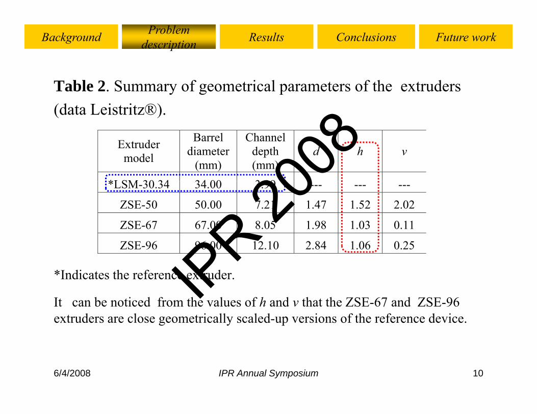
Table 2. Summary of geometrical parameters of the extruders(data Leistritz®).
Extruder model
Barrel diameter
(mm)
Channel depth (mm)
d h v
*LSM 30 34 34 00 3 99*LSM-30.34 34.00 3.99 --- --- ---
ZSE-50 50.00 7.21 1.47 1.52 2.02
ZSE-67 67.00 8.05 1.98 1.03 0.11
*Indicates the reference extruder.
ZSE-96 96.00 12.10 2.84 1.06 0.25
It can be noticed from the values of h and v that the ZSE-67 and ZSE-96 extruders are close geometrically scaled-up versions of the reference device.
6/4/2008 IPR Annual Symposium 10
IPR 20
08

Background Problem description Future workResults Conclusions
Start
Evaluate tT for the reference extruder ,tTf, and
MRt is the mass throughput obtained assuming constant
fMRt for the large extruder, Mi.
E l f hobtained assuming constant residence time.
The screw speed, N, is kept
Evaluate tT for the larger extruder, tTi.
constant during the calculations. tTf = tTi Mi=Mi±ΔMi
Yes
No
Fi 4 I l t d l d f t t
Stop
Yes
6/4/2008 IPR Annual Symposium 11
Figure 4. Implemented scale-up procedure for constant tT.IP
R 2008

Background Problem description Future workResults Conclusions
[After Strutt, 1998]
Fi 5 E t d fi ti f th LSM 30 34Figure 5. Extruder screw configuration for the LSM-30.34extruder.The peroxide injection port, IP, is located at a dimensionless axial distanceThe peroxide injection port, IP, is located at a dimensionless axial distanceequal to 0.45.
For the larger extruders, the length of the screw elements and kneading blocks is scaled up proportionally to d1
6/4/2008 IPR Annual Symposium 12
blocks is scaled-up proportionally to d1.IP
R 2008

Background Problem description Future workResults Conclusions
Table 3. Initially simulated processing conditions.
Extruder model
Mass Throughput
(kg/hr)
Screw speed (rpm)
Peroxide concentration
(wt %) LSM 30 34 5 0 100 150 200 0 01 0 02 0 10LSM-30.34 5.0 100, 150, 200 0.01, 0.02, 0.10
ZSE-50 19.65 100, 150, 200 0.01, 0.02, 0.10
ZSE-67 39.52 100, 150, 200 0.01, 0.02, 0.10
ZSE-96 122.02 100, 150, 200 0.01, 0.02, 0.10
The mass throughput for the larger extruders corresponds to the scaled-up value of this parameter from the equation of constant residence time.
6/4/2008 IPR Annual Symposium 13
IPR 20
08

Background Problem description Future workResults Conclusions
0 02 % 100 LSM 30.34 ref[I] = 0.02 wt% , N=100 rpm
1.00
LSM_30.34_ref
ZSE_96_Rt
ZSE_96_tT
0.60
0.80
sion
less
)
0 20
0.40
DO
F (d
imen
0.00
0.20
0.00 0.20 0.40 0.60 0.80 1.00
D
Figure 6. Degree-of-filling at the center of the screw
Dimensionless axial distance
6/4/2008 IPR Annual Symposium 14
Figure 6. Degree of filling at the center of the screw channel (DOF).
IPR 20
08

Background Problem description Future workResults Conclusions
0 02 % 100 LSM 30 34 ref[I] = 0.02 wt% , N=100 rpm
5.5
LSM_30.34_ref
ZSE_96_RtZSE_96_tT
5.2
sionl
ess)
4.6
4.9
PDI (
dim
en
4.30.60 0.80 1.00
Dimensionless axial distance
Figure 7. PDI variation along the axial distance of the
6/4/2008 IPR Annual Symposium 15
Figure 7. PDI variation along the axial distance of the extruder.
IPR 20
08

Background Problem description Future workResults Conclusions
tav(N=100)[I] = 0.02 wt%
120e
(s)
220
e ( º
C).
tav(N=100)tav(N=150)tav(N=200)
80
100
denc
e tim
212
216
eper
atur
e
Tav(N=100)Tav(N=150)Tav(N 200)
40
60
rage
res
i
204
208
rage
tem
e Tav(N=200)
20
0.00 1.00 2.00 3.00 4.00 5.00
Ave 200
Ave
r
30.3
4
E-50
E-67
E-96
Figure 8. Temperature of reaction and residence time
LSM
-
ZSE
ZSE
ZSE
6/4/2008 IPR Annual Symposium 16
g pvariations for the constant thermal time scale-up approach.
IPR 20
08

Background Problem description Future workResults Conclusions
[I] = 0 02 wt% tav(Ni=100)[I] = 0.02 wt%
100
120m
e (s
)
225
230
re (
ºC)
tav(N 00)tav(Ni=150)tav(Ni=200)T (Ni 100)
60
80
100
side
nce
tim
215
220
225
mep
erat
ur Tav(Ni=100)Tav(Ni=150)Tav(Ni=200)
20
40
60
vera
ge r
es
200
205
210
vera
ge te
m
20
0.00 1.00 2.00 3.00 4.00 5.00
Av 200 Av
-30.
34
SE-6
7
SE-9
6
SE-5
0
Figure 9. Temperature of reaction and residence time
LSM ZS ZSZS
6/4/2008 IPR Annual Symposium 17
g pvariations for the constant SEC scale-up approach.
IPR 20
08

Background Problem description Future workResults Conclusions
[I] = 0 02 wt% SEC[I] = 0.02 wt%
2 2
2.6ss
)tT(N=100)
tT(N=150)
tT(N=200)
1.8
2.2
dim
ensio
nles
( )
1.0
1.4
M/M
Rt (
d
0.60.00 1.00 2.00 3.00 4.00 5.00
E-67
E-96
E-50
-30.
34
Figure 10. Scaled-up mass throughput variations for
ZSE
ZSE
ZSE
LSM
-
6/4/2008 IPR Annual Symposium 18
g p g pboth tT and SEC.
IPR 20
08

Background Problem description Future workResults Conclusions
0 02 % tT(N 100)[I] = 0.02 wt%
2.320
tT(N=100)tT(N=150)tT(N=200)SEC(Ni=100)
2.280
+05
(g/m
ol) ( )
SEC(Ni=150)SEC(Ni=200)
2.240
Mw
E+
2.2000.000 1.000 2.000 3.000 4.000 5.000E-
67
E-96
E-50
30.3
4
Figure 11 Mw and PDI variations for both t and SEC
ZSE
ZSZSE
LSM
-3
6/4/2008 IPR Annual Symposium 19
Figure 11. Mw and PDI variations for both tT and SEC.IP
R 2008

Background Problem description Future workResults Conclusions
Under the constant thermal time scale-up approach:
- Good agreement between the PDIs and Mws of the referencegand scale-up extruders are obtained.
- When the residence time decreases, the temperature of reactionW e t e es de ce t e dec eases, t e te pe atu e o eact oincreases.
- No significant variations of PDI and Mw as a function of theNo significant variations of PDI and Mw as a function of thescrew speed are observed.
Overall, the constant thermal time scale-up procedure is abetter way to scale-up the REX system than the constant SECapproach
6/4/2008 IPR Annual Symposium 20
approach.IP
R 2008

Background Problem description Future workResults Conclusions
3D simulations:
- To perform simulations for specific conditions selected from1D simulations in order to get additional insight of the REXs u at o s o de to get add t o a s g t o t eoperation.
To perform a mixing and residence time distribution (RTD)- To perform a mixing and residence time distribution (RTD)analysis.
- To calculate the average thermal time distribution, Mw, andPDI and compare these results to those of the 1D analysis.
6/4/2008 IPR Annual Symposium 21
IPR 20
08
Background Problem description Future workResults Conclusions
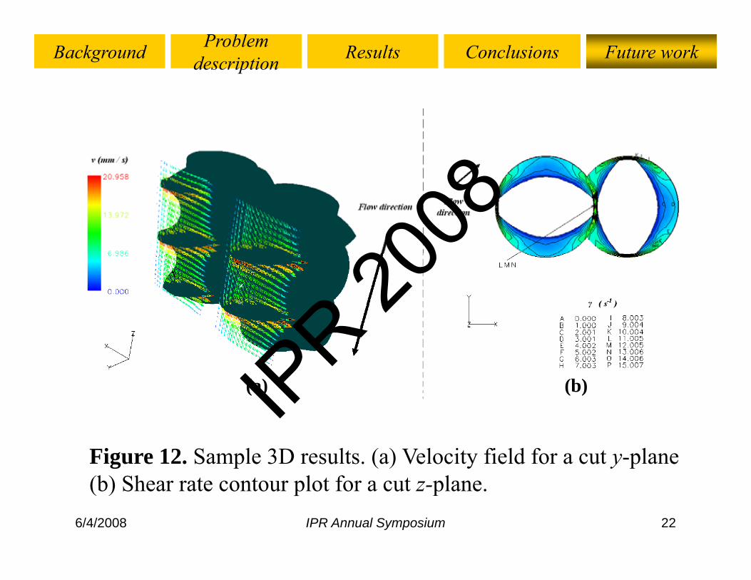
(a) (b)
Figure 12. Sample 3D results. (a) Velocity field for a cut y-plane
6/4/2008 IPR Annual Symposium 22
(b) Shear rate contour plot for a cut z-plane.IP
R 2008

Background Problem description Future workResults Conclusions
Figure 13. Sample 3D results. Particle tracking analysis.
6/4/2008 IPR Annual Symposium 23
IPR 20
08

Scale-up calculations for reactive extrusion operations
Acknowledgements
The financial support from the Mexican National Council forScience and Technology (CONACYT) is gratefullygy ( ) g yappreciated.
6/4/2008 IPR Annual Symposium 24
IPR 20
08

Scale-up calculations for reactive extrusion operations
THANK YOU FOR YOURTHANK YOU FOR YOUR ATTENTION
QUESTIONS/ANSWERSTIMETIME
6/4/2008 IPR Annual Symposium 25
IPR 20
08

Scale-up calculations for reactive extrusion operations
6/4/2008 IPR Annual Symposium 26
Figure A.1. General description of an extrusion operation.IP
R 2008

Scale-up calculations for reactive extrusion operations
(a) (b)[After Booy, 1978] [After Yang and Manas-Zloczower, 1992]
Figure A.2. a) Additional geometrical considerations for a twin
tαπ
screw extruder system. b) Kneading block geometry
( )DC αcos= [A 2]
6/4/2008 IPR Annual Symposium 27
22t
i nαπα −= ( )iSL DC αcos=[A.1] [A.2]
IPR 20
08

0 02 % 100 LSM 30 34 f
Scale-up calculations for reactive extrusion operations
[I] = 0.02 wt% , N=100 rpm
220C
)
LSM_30.34_ref
ZSE_96_Rt
ZSE_96_tT
210
erat
ure
( ºC
190
200
rage
tem
ep
1800.00 0.20 0.40 0.60 0.80 1.00
Ave
Dimensionless axial position
Figure A.3. Temperature variation along the axial
6/4/2008 IPR Annual Symposium 28
Figure A.3. Temperature variation along the axial distance of the extruder.
IPR 20
08

- Reaction kinetics for the peroxide-initiated degradation of PP
Scale-up calculations for reactive extrusion operations
Reaction kinetics for the peroxide initiated degradation of PP (Tzoganakis et al. 1988). Initiation, chain scission, transfer, thermal degradation, termination by disproportionation are the steps considered by the model.steps considered by the model.
010 32
QQIkf
dQ
IkdtdI
D
−
−=
( )2102
01
23 22 QQQ
QQQQ −= [A.4]
( ) ( )01
01
01
23/3/
22
2
QQQdQQQ
QIkf
dtdQ
QQIkf
dt
Dp
Dp
+−
−=
−= 01QQ
( )
( )_
010
_
/
/
QQmM
QQmM n =
[A.5]
[A.3]
- I is the peroxide concentration; fp and kd, are the peroxide decomposition
( ) ( )01
0132 23/3/2
QQQQQ
Ikfdt
dQDp −
−+−=
( )
( )230
_120
/
/
QQmM
QQmM
z
w
=
= [A.5]
efficiency and rate constant of decomposition, respectively. t is the time; and Qi is the ith moment of the molecular weight distribution. Mn, Mw and Mz are the number-, weight- and z- average molecular weights, respectively; and m0 is the monomer molecular weight
6/4/2008 IPR Annual Symposium 29
respectively; and m0 is the monomer molecular weight.IP
R 2008

- Equations A 6-A 9 needs to
Scale-up calculations for reactive extrusion operations
- Mw is a time dependent function; it depends on the evolution of the reaction (eq
- Equations A.6-A.9 needs to be declared in POLYFLOW® as “user d fi d f i ”evolution of the reaction (eq
15).defined functions”.
- The ith moment of the molecular weight distribution( )
__[A 6] molecular weight distribution
are calculated from relations proposed by Tzoganakis et al. (1988)
( )120 /QQmMW =
⎪⎪
⎨
⎧ <−
0
..
10
. , γγγ n
K
[A.6]
(1988).- The power-law consistency
index, K, and the power-law ⎪⎪
⎩
⎪⎨
>=
− 0
..
1.
0
, γγγ
γη
nK [A.7]
, , pindex, n, are expressed as polynomial functions (Strutt, 1998)
),(__
TMKK W=
),(__
TMnn W= [A.9]
[A.8]
6/4/2008 IPR Annual Symposium 30
1998).IP
R 2008

Scale-up calculations for reactive extrusion operations
(b)(a) (b)
Figure A.4. (a) Screws and (b) flow-field meshed t ti l bd i
6/4/2008 IPR Annual Symposium 31
computational subdomains.IP
R 2008
3D simulations.
Scale-up calculations for reactive extrusion operations
- Simulation of the flow in conveying screw elements of a CSCO extruder.
- POLYFLOW®, a FEM software, is used; it applies the “mesh superposition technique” (Avalosse and Rubin, 2000). This technique is especially useful in describing the time q p y gdependency of the flow, which is due to the rotation of the screws.A ti P d t d t t ( t d t t f fi d- Assumptions: Pseudo-steady state (steady state for a fixed position of the screws). Newtonian and isothermal flow.
- Boundary conditions: Screw rotating speed=10 rpm. Gravity y g p p yand inertia forces neglected. Non-slip conditions on solid boundaries.M d l G li d N t i fl id Vi it 5 0E04 P
6/4/2008 IPR Annual Symposium 32
- Model: Generalized Newtonian fluid. Viscosity=5.0E04 Pa·sIP
R 2008

T bl A 1 P id h lf li i T bl A 2 P id h lf
Scale-up calculations for reactive extrusion operations
Table A.1 Peroxide half-lives in melt (sample results).Ni=150 rpm. [I]=0.02 wt%
Table A.2 Peroxide half-live time as a function of the temperature of reaction.Ni 150 rpm. [I] 0.02 wt% p
Extruder model
ConstanttT
ConstantSEC
Temperature(oC)
[I]1/2
(s)
LSM-30.34 3.25 ---
ZSE-50 3.33 2.23
180 74.00190 36.30200 18 35ZSE-67 3.80 3.68
ZSE-96 4.33 3.92
200 18.35
210 9.54220 5 10
For the higher values of the average temperature of reaction, the lower values of this parameter are observed
220 5.10
6/4/2008 IPR Annual Symposium 33
p(in agreement with results of Fig. 8).
IPR 20
08