Embed Size (px)
Citation preview

ARTICLE IN PRESS
0734-743X/$ - s
doi:10.1016/j.iji
�CorrespondE-mail addr
International Journal of Impact Engineering 34 (2007) 859–873
www.elsevier.com/locate/ijimpeng
Scaling the response of circular plates subjected to large andclose-range spherical explosions. Part I: Air-blast loading
A. Neubergera,b,�, S. Pelesc, D. Rittela
aTechnion, Faculty of Mechanical Engineering, Israel Institute of Technology, 32000 Haifa, IsraelbMOD, Tank Program Management, Hakirya, Tel-Aviv, Israel
cIMI, Central Laboratory Division, Ramat Hasharon, P.O. Box 1044, Israel
Received 5 January 2006; accepted 9 April 2006
Available online 12 June 2006
Abstract
This two-part paper addresses scaling of the dynamic response of clamped circular plates subjected to close-range and
large spherical blast loadings.
Full-scale experiments involving actual geometries and charges are quite involved and costly, both in terms of
preparation and measurements. For these reasons, scaled-down experiments are highly desirable. However, the validity of
such experiments remains to be firmly established, and this is the main objective of this paper.
In this study, similarity is obtained by using replica scaling for all geometrical parameters, while the blast effect is scaled
by using the well-known Hopkinson scaling law. We also consider the overall effect of the strain rate sensitivity and
variability of material properties with plate thickness on the response of the scaled model.
This study presents numerical and experimental results from a series of controlled explosion experiments. The first part
of the paper deals with spherical charges exploding in free air, while the second part deals with the same charges flush
buried in dry sand. A good agreement between numerical simulation predictions and test results was obtained, so that the
main result of the two papers is that scaling can be successfully applied to assess the dynamic response of armor plates
subjected to close-range large explosions.
r 2006 Elsevier Ltd. All rights reserved.
Keywords: Close-range; Large blast; Dynamic response; Circular plate; Scaling
1. Introduction
Understanding the dynamic behavior of blast loaded armor steel plates is a key to successful protectionprojects. The literature on blast loaded plates is quite abundant. Numerous studies of experimental and/ornumerical nature have been carried out and reported (see, e.g. [1–9]). These studies characterize the differentfailure modes and the relationship between deformation and tearing of clamped blast loaded plates. Thefailure modes were first defined by Menkes and Opat [10] for the case of impulsively loaded clamped beams.
ee front matter r 2006 Elsevier Ltd. All rights reserved.
mpeng.2006.04.001
ing author. MOD, MANTAK, Tank Program Management, Hakirya, Tel-Aviv, Israel.
ess: [email protected] (A. Neuberger).

ARTICLE IN PRESS
Nomenclature
A Johnson–Cook (J–C) coefficientB J–C coefficientC J–C coefficientCi polynomial coefficientsD plate diameterI impulsem J–C coefficientn J–C coefficientP blast pressureR distance from center of spherical chargeS scaling factort plate thicknessT temperatureV relative volume of the gas products to the initial explosive stateW charge weightZ scaled distanceE energyd peak deflectione; _e strain, strain ratey angle of incidencer material densitys stresst timez scaled impulseP characteristic similarity parameter
A. Neuberger et al. / International Journal of Impact Engineering 34 (2007) 859–873860
The classification was as follows: mode I for large inelastic deformation, mode II for tearing at the support,and mode III for shear failure at the support. These failure modes were also adopted for blast loaded circularplates, and further subdivisions were observed and defined by other authors. In contrast to the large numberof studies mentioned previously, the literature on scaling (similarity) of the structural response is quite sparse.Wen and Jones [11] investigated the scaling of metal plates subjected to impact and concluded that geometricalscaling can be applied. These authors also reported that strain rate sensitivity does not significantly affectscaling for their experiments. Jacob et al. [12] investigated scaling aspects of quadrangular plates subjected tolocalized blast loads. The effects of varying the charges’ weight and plate geometries on the deformation weredescribed and analyzed. Furthermore, a modified dimensionless number was introduced to represent thequadrangular plate’s response to a localized disc charge. The validity of the presented results is limited to theinvestigated small plate geometries and loading conditions, while numerical simulations and experiments forlarger explosions are still required.
Raftenberg presented a study on close-range small blast loading on a steel disc [13]. This study com-pared experimental data to several numerical finite elements calculations, based on different con-stitutive models in order to validate specific dynamic material parameters. The Johnson–Cook model forRHA steel was found to produce results in reasonable agreement with experiments for the problem at hand.Hanssen et al. [14] investigated the behavior of aluminum foam panels subjected to close-range blast loading.This study addressed the performance of additional sacrificial layers as a protecting layer. However, it wasobserved that the energy and impulse transfer to the protected structure was not reduced by adding asacrificial foam panel, but contrary to the expectations, the impulse increased due to the proximity of theexplosion.

ARTICLE IN PRESSA. Neuberger et al. / International Journal of Impact Engineering 34 (2007) 859–873 861
The combination of scale modeling of the dynamic response of a plate subjected to a very large explosion
from a close-range was not studied yet, to the best of the authors’ knowledge.Therefore, these papers present scaling aspects of the quantities that characterize the dynamic response of a
plate subjected to close-range large blasts. Part I of the study reports finite elements simulations andexperiments of blast loaded circular plates subjected to explosions in free air. The numerical calculations andthe tests were conducted on different scale factors S (where S ¼ 2 refers to one-half scaling), where thereference plate (S ¼ 1) is 0.05m thick with a 2m diameter. Part II of the study addresses the effects of sand-buried charges. The main outcome of the two papers is that scaling can be applied to analyze armor platessubjected to close-range large air blasts as well as buried charges. This study also shows that the variation ofmechanical properties with plate thickness affects the similarity result and should therefore be taken intoaccount.
The paper is organized as follows: Section 2 presents elements of the physical similarity and scale modelingused in this work, followed by Section 3 that details the numerical approach. Section 4 describes the test setupand measuring technique, while Section 5 presents the numerical results, followed by the experimental results.Section 6 discusses the key points of the study, followed by concluding remarks.
2. Elements of scaling theory
The validation of physical similarity of a specific phenomenon is crucial for proper scaling. Before a largescale prototype is built, experiments on a small scale model are required. However, one must know how to scalethe model experimental results up to the full scale prototype. The concept of physical similarity was stated byBarenblatt [15] as a natural generalization of similarity in geometry, so that ‘physical phenomena are called
similar if they differ only in respect of the numerical values of the dimensional governing parameters while the
values of the corresponding dimensionless parameters (P-terms) being identical’. The objective is to obtainidentical relationships between quantities that characterize both, the prototype, regarding the original size, andthe model, regarding the scaled-down phenomena.
The principles of scaling and the relationships between the small scale model parameters and the full-scaleprototype parameters were stated by Jones [16]. Here we will present the relevant parameters for theinvestigated problem in terms of proportion between the prototype parameter (superscripts P) and thecorresponding model parameter (superscripts M), as follows:
–
Linear dimensions are proportional to the scale factor, xPi ¼ xMi � S.
– Angles are the same, aPi ¼ aMi . – Densities of materials are the same, rPi ¼ rMi . – Stresses of each material are the same, sPi ¼ sMi . – Characteristic times are proportional to the scale factor, tPi ¼ tMi � S. – Strains are identical, ePi ¼ eMi . – Loads are the same, and must act at scaled locations, FPi ¼ FMi at xP
i ¼ xMi � S.
–
Deformations at geometrically scaled locations for corresponding scaled times are proportional to the scalefactor, dPi ¼ dMi � S at tPi ¼ tMi � S.–
Angular deformations are the same, oPi ¼ oMi .
It should be noted that several phenomena may not scale according to these principles. For examplegravitational forces cannot be scaled according to the basic principles of geometrically similar scaling.However, here high accelerations are involved therefore the gravitational forces are not significant and canthus be neglected. Strain rate sensitivity in a small-scale model is scale factor times larger than that in ageometrically similar full-scale prototype. For the case at hand, considering the actual strain rates producedduring the dynamic bulging process, the material properties are taken to be approximately scale-independent.Finally, fracture cannot be scaled according to the basic principles of geometrically similar scaling. However,fracture is beyond the scope of the present work.
When scaling spherical blast wave phenomena, the most common scaling method is Hopkinson, or ‘‘cuberoot’’ scaling law as shown by Baker [17]. This scaling law states that self-similar blast waves are produced at

ARTICLE IN PRESSA. Neuberger et al. / International Journal of Impact Engineering 34 (2007) 859–873862
identical scaled distances when two explosive charges of similar geometries and explosive, but of dif-ferent weight, are detonated in the same atmosphere. For explosions in air, the Hopkinson scaled parametersare [17]:
Z ¼R
E1=3; t� ¼
t
E1=3; z ¼
I
E1=3, (1)
where Z is the scaled distance, t� is the characteristic scaled time of the blast wave, z is the scaled impulse, R isthe distance from center of blast source, and E is the source blast energy. This law implies that all quantitieswith dimension of pressure and velocity are unchanged through scaling, i.e. for the same value of Z (note thatE can be replaced by the blast source weight W). In this study, Hopkinson’s method was used to calculate thecorresponding charge weight for the scaled down model as follows:
WM ¼WP=S3. (2)
3. Numerical simulations
The numerical simulations were carried out using LS-DYNA finite element code [18]. The software has theability to simulate dynamic structural response in several ways, including pure Lagrangian, and coupledLagrange–Eulerian methods. The purely Lagrangian approach combined with a simplified engineering blastmodel is more desirable since it reduces the calculation time. However, both methods were used and comparedwith the experimental data. The multi-material Eulerian formulation is part of the Arbitrary-Lagrangia-n–Eulerian (ALE) solver within LS-DYNA. By combining the ALE solver with an Eulerian–Lagrangiancoupling algorithm, a structural or Lagrangian mesh can interact with the gas products or Eulerian mesh. Thistechnique was used for the ranges where the simplified blast model produced uncertain impulse duration as aresult of blast proximity.
3.1. Simplified blast model
‘Load-blast’ boundary condition, which is implemented in LS-DYNA, was used to load the tested circularplate with the appropriate varying pressure distribution. This function is based on an implementation byRandors-Pehrson and Bannister (1997) of the empirical blast loading functions by Kingery and Bulmash [19]that were implemented in the US Army Technical Manual ConWep code [20].
The blast loading equation is stated as follows:
PðtÞ ¼ Pr � cos2 yþ Pi � ð1þ cos2 y� 2 cos yÞ, (3)
where y is the angle of incidence, defined by the tangent to the wave front and the target’s surface, Pr is thereflected pressure, and Pi is the incident pressure. This blast function can be used for the following two cases:free air detonation of a spherical charge, and ground surface detonation of a hemispherical charge. Tocalculate the pressure over certain predefined group of surfaces related to the geometry of the analyzedstructure, the model uses the following inputs: equivalent weight of TNT explosive, the spatial coordinate ofthe detonation point, and the type of blast (spherical or hemispherical). The actual impulse, I, correspondingto the charge’s weight and distance to the target, can be derived from the ConWep database [20] that isimplemented into the ‘load-blast’ function of LS-DYNA software. For example, considering the problemanalyzed here, the spherical TNT charge’s weight is W ¼ 50 kg, and the distance from the target is R ¼ 0:5m.Then, the impulses are I(incident) ¼ 1563 kPams, and I(reflected) ¼ 45,220 kPams.
Note that the model accounts for the angle of incidence of the blast wave, but it does not account forshadowing by intervening objects or for the confinement effects, causing the blast to focus on a certain zone.
3.2. Material behavior
The ALE model involves three different material types. The first material model represents the rolledhomogeneous armor (RHA) steel plate, followed by the TNT spherical explosive charge, and finally the

ARTICLE IN PRESSA. Neuberger et al. / International Journal of Impact Engineering 34 (2007) 859–873 863
surrounding air media, which is used to fill the space affected by the explosive charge. Note that in the purelyLagrangian approach, only one type of material model is needed, namely for the steel plate.
The circular steel plate is represented by a finite element mesh created by FEM-PATRAN preprocessorsoftware. By using the inherent symmetry of the studied problem calculation time can be saved. Thus, only aquarter of the circular plate was modeled with the appropriate boundary conditions applied along thesymmetry planes as shown in Fig. 1. The entire model was constructed from constant stress hexagonal solidelements formulation with one integration point.
To represent the dynamic mechanical behavior of the RHA steel two constitutive material models werecompared. The first model represents a strain rate insensitive bilinear material. The second model represents astrain rate sensitive material, represented by the Johnson–Cook (J–C) constitutive model [21]. The J–C modelis stated as follows:
sy ¼ Aþ B � enp
� �� ð1þ c � ln _e�Þ � ð1� TmÞ, (4)
where A, B, c, n and m are the J–C material coefficients, as listed in Table 1 [20,21], ep is the effective plasticstrain, _e� ¼ _ep=_e0 is the effective plastic strain rate at a reference strain rate _e0 ¼ 1 s�1, and the homologoustemperature T ¼ ðT 0 � T 0roomÞ=ðT
0melt � T 0roomÞ where T0 is the material’s temperature, T0room is the room
temperature, and T0melt is the material’s melting temperature.The J–C constitutive material model is incorporated with a polynomial equation of state which is linear in
internal energy E. The pressure P is given by
P ¼ C0 þ C1mþ C2m2 þ C3m3 þ ðC4 þ C5mþ C6m2ÞE, (5)
where the terms C2m2 and C6m
2 are set to zero if m ¼ ðr=r0Þ � 1o0, and r/r0 is the ratio of the current to initialdensity.
Fig. 1. Finite elements model: (a) symmetry B.C.; (b) constrained B.C.; (c) ‘load-blast’ B.C.; (d) entire model including measurement
points.
Table 1
RHA class 1 mechanical properties and the corresponding Johnson–Cook coefficients [24]
t (mm) sy (MPa) sUTS (MPa) eL (%) E (GPa) n Hardness (HBW) A (MPa) B (MPa) n c m
3–20 950 1250 9 380–430 950 560
21–40 900 1150 10 210 0.28 340–390 900 545 0.26 0.014 1
41–80 850 1050 11 300–350 850 355

ARTICLE IN PRESSA. Neuberger et al. / International Journal of Impact Engineering 34 (2007) 859–873864
The TNT explosive charge was modeled via Jones–Wilkins–Lee (JWL) equation of state (EOS) for explosivedetonation products [22]. The pressure field is given by
P ¼ A 1�o
R1V
� �e�R1V þ B 1�
oR2V
� �e�R2V þ
oE 0
V, (6)
where A, B, C, R1, R2, and o are constants that can be found in the literature [23], V ¼ v=v0 is the relativevolume of the gas products to the initial explosive state, and E0 is the energy per unit volume.
The medium in which the blast wave propagates (air) was modeled with a linear polynomial EOS for linearinternal energy, which is given by
P ¼ C0 þ C1mþ C2m2 þ C3m3 þ C4 þ C5mþ C6m
2� �
E�, (7)
where m ¼ r=r0 � 1 with r=r0 being the ratio of the current to initial density, C1,y,6 are polynomialcoefficients, and E* has units of pressure. To model gases, the gamma law EOS can be used. This implies thatC0 ¼ C1 ¼ C2 ¼ C3 ¼ C6 ¼ 0 and C4 ¼ C5 ¼ g� 1, where g is the ratio of specific heats. Therefore Eq. (7)becomes
P ¼ ðg� 1Þrr0
E�. (8)
4. Test setup
Two different scaled-down similar test rigs (of scale-down factors S ¼ 2 and 4) were built in order toexperimentally assess the applicability of scale-down modeling of the studied problem. The experimental testsetup of each structure is shown in Fig. 2. The target plate was supported by two thick armor steel plates withcircular holes that were tightened together with bolts and clamps. The thick plate that faces the charge has ahole with inclined side walls to prevent reflection of the blast wave to the tested plate as shown schematically inFig. 3.
The measurement of the maximum dynamic deflection of the plate was achieved by means of a speciallydevised comb-like device. The teeth of the comb possess a gradually decreasing height, as shown in Fig. 4.When positioned under the dynamically deflecting plate, the long teeth are permanently bent while those thatare shorter than the maximum deflection remain intact. Therefore, a direct estimation of the maximumdeflection is immediately available after the blast test. We found that this inexpensive device provides asufficiently accurate measure of the dynamic deflection. Note that the accuracy of the measurement is relatedto the height difference between the teeth.
The spherical TNT charges were hanged in air using fisherman’s net and were ignited from the center of thecharge.
Fig. 2. Experimental setup at 2 different scales (S ¼ 4, left, and S ¼ 2, right)

ARTICLE IN PRESS
Fig. 4. Comb-like device for dynamic deflection measurement.
Spherical TNTcharge
R t
Measuring comb
δ
D
Clamp Clamp
Bridge
Target plate
W
Fig. 3. Schematic drawing of the test rig and the measurement setup.
A. Neuberger et al. / International Journal of Impact Engineering 34 (2007) 859–873 865
5. Results
5.1. Numerical results
The numerical calculations comprised 4 distinct stages, and the same problem was calculated each time atdifferent scale factors, namely S ¼ 1, 2, 4, 10, and 0.5.
The first stage deals with the boundary conditions and their influence on the deflection profile of the plate.Three different boundary conditions were investigated: ‘free’, ‘constrained’ (or clamped), and a characteristic‘structure’ as shown in Fig. 5. The characteristic structure enables us to analyze the effect of supporting sidewalls on the dynamic response of the plate. The objective of this preliminary study was to investigate thedifferences between the three dynamic responses and select the most appropriate boundary conditions for thefollowing calculations.
The second stage involves selection of a simple rate-insensitive bilinear material model and calculation ofthe deflections and stresses at different scaling factors. Here the objective is to explore scalability of thedynamic response with ‘‘ideal’’ parameters.
The third stage introduces rate-sensitivity of the mechanical properties of the steel plate through theJohnson–Cook model [21]. The objective of this stage is to study the effect of the strain rate sensitivity on thedynamic response at different scale factors for the problem at hand.
Finally, stage 4 addresses variability of the material properties with the rolled plate thickness as a result ofthe manufacturing process. This stage was carried out at three different scale factors. The results of each stagewill now be presented and discussed.

ARTICLE IN PRESS
0 0.5 1 1.5 2 2.5 3 3.5 40
0.5
1
1.5
2
2.5
Scaled time, τ·S msec
Nor
mal
ized
max
imum
def
lect
ion,
δ /
t
FreeConstrainedStructure
Fig. 6. Midpoint normalized deflection vs. scaled time for free, constrained, and structure boundary conditions.
Fig. 5. Comparison between different boundary conditions: (a) free, (b) constrained; (c) structure.
A. Neuberger et al. / International Journal of Impact Engineering 34 (2007) 859–873866
5.1.1. Stage 1: influence of the boundary conditions
The effect of the three different boundary conditions on the dynamic response (i.e. deflection–time history)at the midpoint of the plate is shown in Fig. 6. The following parameters were taken: plate thicknesst ¼ 0:05m, plate diameter D ¼ 2m, charge’s weight W ¼ 50 kg TNT, and distance from the plate’s surface tothe center of the charge R ¼ 0:5m. The RHA class 1 material properties were represented via bilinear modelwith the following parameters: yield strength sy ¼ 1000MPa, Young’s modulus E ¼ 210GPa, and hardeningplastic modulus Ep ¼ 2GPa. The deflection at the midpoint of the plate is calculated as the difference betweenthe midpoint and the circumference vertical displacements. Fig. 6 shows the deflection time history of the blastloaded plate for each type of boundary condition. It can be seen that the peak deflection occurs at scaled timesof the order of �2ms. The ‘free’ and ‘structure’ types of boundary conditions produce relatively equal peakdeflections while the ‘constrained’ type has a peak deflection which is approximately 20% smaller than theothers. Furthermore, even though the ‘free’ and ‘structure’ boundary conditions are quite similar in their peakdeflection, it can be seen that they yield a different duration of the bulging process, where the deflection in the‘structure’ boundary condition lasts longer than in the ‘free’ type as a result of the added inertia of the sidewalls. From this point further on, we applied the ‘constrained’ boundary conditions only, since they werefound to be closer to the actual experimental boundary conditions.
5.1.2. Stage 2: scaling with bilinear material model
The objective of the second stage is to validate the scale modeling using the combined Hopkinson-Replicamethod for ideal material properties of the blast loaded plate, namely bilinear material properties as shown

ARTICLE IN PRESS
0 0.5 1 1.5 2 2.5 3 3.5 40
0.2
0.4
0.6
0.8
1
1.2
1.4
1.6
1.8
2
Scaled time, τ·S msec
Nor
mal
ized
max
imum
def
lect
ion,
δ /
t
S = 10S = 4S = 2S = 1S = 0.5
Fig. 7. Normalized midpoint deflection vs. scaled time at different scales (bilinear material model).
0 0.5 1 1.5 2 2.5 3 3.5 40
0.2
0.4
0.6
0.8
1
Scaled time, τ·S msec
Nor
mal
ized
effe
ctiv
e st
ress
, σef
f / σ
y
S = 10S = 4S = 2S = 1S = 0.5
Fig. 8. Normalized stresses vs. scaled time at different scales (bilinear material model).
A. Neuberger et al. / International Journal of Impact Engineering 34 (2007) 859–873 867
previously. Fig. 7 shows the normalized midpoint deflection scaled time history at various scaling factorsranging from S ¼ 0:5 to 10. The plate thickness at scale factor S ¼ 1 is t ¼ 0:05m, plate diameter D ¼ 2m,charge weight W ¼ 50 kg TNT, and the distance from center of charge R ¼ 0:5m. This is equivalent toselecting a scaling factor of S ¼ 4 for instance, so that t ¼ 0:0125m, D ¼ 0:5m, and R ¼ 0:125m. In that casethe corresponding charge is scaled down to W ¼ 0:781 kg TNT. This figure shows that all the curves mergetogether, showing an excellent scaling of the plates midpoint deflection. It should be mentioned that the sameprocedure was applied for different ‘‘measurement’’ points on the plate (Fig. 1) at all scaling factors, andidentical results were obtained. Fig. 8 shows the scaled time history of the normalized stresses at the midpoint

ARTICLE IN PRESS
0 0.5 1 1.5 2 2.5 3 3.5 40
0.2
0.4
0.6
0.8
1
1.2
1.4
1.6
1.8
2
Scaled time, τ·S msec
Nor
mal
ized
max
imum
def
lect
ion,
δ /
t
S = 10S = 4S = 2S = 1S = 0.5
Fig. 9. Normalized midpoint deflection vs. scaled time at different scales (Johnson–Cook constitutive model).
A. Neuberger et al. / International Journal of Impact Engineering 34 (2007) 859–873868
of the plate for the corresponding conditions shown above. One should again emphasize that the material isconsidered as rate-insensitive in these calculations.
5.1.3. Stage 3: scaling with strain-rate sensitive material model (J– C)
The objective of the third stage is to assess the influence of the material’s strain-rate sensitivity on the scalemodeling of blast loaded plate. Here, the steel plate was modeled using Johnson–Cook model [21] with thefollowing coefficients: A ¼ 1000MPa, B ¼ 500MPa, c ¼ 0:014, n ¼ 0:26, and m ¼ 1. Fig. 9 shows thenormalized midpoint deflection scaled time history for various scaling factors. Here too, it can be seen that allthe curves merge almost perfectly to a single curve, thus showing excellent scaling of the problem. Thenumerical calculations show that for S ¼ 1, the strain rate at the maximum deflected elements is of the orderof _eS¼1 � 200 s�1, whereas for S ¼ 10, it reaches _eS¼10 � 1000 s�1. In this range of strain rates, theJohnson–Cook model [21] predicts a very small change in the yield or flow stress. Therefore, one may concludethat, given the actual strain rates produced during the dynamic bulging process, strain-rate sensitivity has anegligible effect on the scalability of the problem at hand, for the range of scaling factors investigated here.However, this may not always be the case when highly strain rate sensitive materials are considered.
5.1.4. Stage 4: scaling with material properties variability with thickness (J– C)
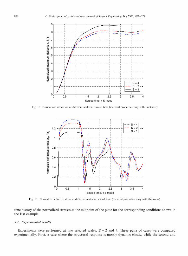
The objective of this stage is to assess the extent to which a certain variability of the mechanical propertiesof the rolled plate, for each plate’s thickness, may affect the validity of the present scaling procedures. To bemore specific, let us consider the RHA class 1 armor steel material. Due to manufacturing limitations itsproperties vary with the thickness, as shown in Table 1. For example, a plate of t ¼ 0:01m thickness has ayield strength sy ¼ 950MPa and UTS strength sUTS ¼ 1250MPa. When the thickness becomes t ¼ 0:04m thecorresponding material properties are reduced to following values: yield strength sy ¼ 850MPa and UTSstrength sUTS ¼ 1050MPa [24]. The corresponding Johnson–Cook coefficients in this table were taken asfollows: A is the yield strength of the material, B is calculated to obtain the UTS strength at the givenmaximum elongation, while n, c, and m remain unaffected and can be found in literature [21]. Thisinvestigation was performed at three different scale factors S ¼ 1, 2, and 4 for the same problem as before.The simulations results are shown in Figs. 10 and 11, where the differences between the dynamic responses ateach of the three scale factors are shown. In order to further study the influence of the material properties,larger plastic strains were investigated. This was achieved by modeling a thinner plate and a larger charge from

ARTICLE IN PRESSA. Neuberger et al. / International Journal of Impact Engineering 34 (2007) 859–873 869
closer range as follows: at scale factor S ¼ 1 the plate thickness is t ¼ 0:04m, plate diameter D ¼ 2m, chargeweight W ¼ 70 kg TNT, and the distance from center of charge R ¼ 0:26m. Fig. 12 shows the normalizedmidpoint deflection scaled time history at the three scaling factors S ¼ 1, 2, and 4. It can be seen that, due tothe difference between the material properties for each material thickness, the resulting curves of each scalefactor diverge from each other to approximately �7% peak deflection, starting with scale factor S ¼ 1 up toscale factor S ¼ 4. Therefore, scale modeling of the present problem is distorted, so that the deviation shouldbe taken into account when scaling the results from the model up to the prototype. Fig. 13 shows the scaled
0 0.5 1 1.5 2 2.5 3 3.5 40
0.2
0.4
0.6
0.8
1
1.2
1.4
1.6
1.8
2
Scaled time, τ·S msec
Nor
mal
ized
max
imum
def
lect
ion,
δ /
t
S = 4S = 2S = 1
Fig. 10. Normalized deflection at different scales vs. scaled time (material properties vary with thickness).
0 0.5 1 1.5 2 2.5 3 3.5 40
0.2
0.4
0.6
0.8
1
1.2
Scaled time, τ·S msec
Nor
mal
ized
effe
ctiv
e st
ress
, σef
f / σ
y
S = 4S = 2S = 1
Fig. 11. Normalized effective stress at different scales vs. scaled time (material properties vary with thickness).
ARTICLE IN PRESS
0 0.5 1 1.5 2 2.5 3 3.5 40
1
2
3
4
5
6
7
8
9
Scaled time, τ·S msec
Nor
mal
ized
max
imum
def
lect
ion,
δ /
t
S = 4S = 2S = 1
Fig. 12. Normalized deflection at different scales vs. scaled time (material properties vary with thickness).
0 0.5 1 1.5 2 2.5 3 3.5 40
0.2
0.4
0.6
0.8
1
1.2
Scaled time, τ·S msec
Nor
mal
ize
deffe
ctiv
e st
ress
, σef
f / σ
y
S = 4S = 2S = 1
Fig. 13. Normalized effective stress at different scales vs. scaled time (material properties vary with thickness).
A. Neuberger et al. / International Journal of Impact Engineering 34 (2007) 859–873870
time history of the normalized stresses at the midpoint of the plate for the corresponding conditions shown inthe last example.
5.2. Experimental results
Experiments were performed at two selected scales, S ¼ 2 and 4. Three pairs of cases were comparedexperimentally. First, a case where the structural response is mostly dynamic elastic, while the second and

ARTICLE IN PRESS
Table 2
Experimental and numerical results
S t (m) D (m) W (kg TNT) R (m) d/t Experimental d/t Numerical
2 0.02 1 3.75 0.2 2.70 2.62
4 0.01 0.5 0.468 0.1 2.60 2.59
2 0.02 1 8.75 0.2 5.35 5.24
4 0.01 0.5 1.094 0.1 4.85 4.98
2 0.02 1 8.75 0.13 8.25 8.15
4 0.01 0.5 1.094 0.065 7.45 7.72
Fig. 14. Experimental result at S ¼ 4 (left) and S ¼ 2 (right).
A. Neuberger et al. / International Journal of Impact Engineering 34 (2007) 859–873 871
third cases treat increasing plastic strains in the structural dynamic response. Table 2 lists the variousexperimental parameters compared to the numerical predictions of the experiments.
For example, let us select the first case where the model has scale factor S ¼ 2, plate thickness t ¼ 0:02m,plate diameter D ¼ 1m, charge weight W ¼ 3:75 kg TNT, and the plate distance from center of chargeR ¼ 0:2m. This represents a charge of 30 kg TNT for the full scale prototype, where S ¼ 1, t ¼ 0:04m,D ¼ 2m, and R ¼ 0:4m. In that case the experimental normalized peak deflection d=t ¼ 2:7, while thenumerical matching parameter d=t ¼ 2:62. This is equivalent to selecting a scaling factor of S ¼ 4 for instance,so that t ¼ 0:01m, D ¼ 0:5m, W ¼ 0:468 kg TNT, and R ¼ 0:1m. In that case the corresponding normalizedpeak deflection remains similar d=t ¼ 2:6 for the experimental data and match the numerical parameterd=t ¼ 2:59.
Consider now the third case where large dynamic plastic deformations are achieved. The model has scalefactor S ¼ 2, plate thickness t ¼ 0:02m, plate diameter D ¼ 1m, charge weight W ¼ 8:75 kg TNT (thatrepresents 70 kg TNT for the full scale prototype, S ¼ 1), and the plate distance from center of chargeR ¼ 0:13m. In that case the experimental normalized peak deflection d=t ¼ 8:25 while the numerical matchingparameter d=t ¼ 8:15. This is equivalent to selecting a scaling factor of S ¼ 4 for instance, so that t ¼ 0:01m,D ¼ 0:5m, W ¼ 1:094 kg TNT, and R ¼ 0:065m. In that case the corresponding normalized peak deflectionremains similar d=t ¼ 7:45 for the experimental data and match the numerical parameter d=t ¼ 7:72. Fig. 14compares the residual plastic deformations for both scaling factors, S ¼ 2 and 4, regarding the third case.
From this table, it appears that the experimental and numerical results are in excellent agreement. It shouldbe noted that, as long the dynamic response is mostly elastic the varying material properties with thicknesshave no effect on the scaling, as expected. However, when the dynamic deformations are mainly plastic, thescaling is affected, as discussed previously.
6. Discussion
This paper addresses the delicate problem of scaling the dynamic response of circular RHA steel platesto large bare spherical air blast explosions (high explosive without fragmentation, not confined, and

ARTICLE IN PRESSA. Neuberger et al. / International Journal of Impact Engineering 34 (2007) 859–873872
non-localized). The scaling employed here is geometrical (replica) for the structure and based on Hopkinson’slaw for the explosive charge. While this concept is not new, it has not been previously applied and verified tothe specific problem of large charges that are initiated from a close-range.
Three different types of boundary conditions were investigated in the preliminary stage. For each case, adifferent response was observed, past an initial period. While some similarity was observed between the ‘‘free’’and ‘‘structure’’ conditions, it was decided to consider further only the ‘‘constrained’’ condition that is morepractical from an experimental point of view. In any case, care should be exercised to replicate the actualboundary conditions of the prototype for the scaled problem. One should also keep in mind that the presentsimulations do not address fracture. If a critical strain or stress is adopted as the failure criterion, its value maywell be reached during the inertial phase for which all boundary conditions yield identical results.
Scaling model is affected when the ‘‘same’’ material has different mechanical properties at different scalingfactors. Thus, scaling up the results should take into account the effect of the varying mechanical propertieswith thickness according to the calculated numerical results. Note that the problem treated here is not affectedby strain rate sensitivity of the RHA steel. The observed variability is of the order of 5–10% for scaling factorS ¼ 2, which should be taken into account for engineering design purposes.
As a final remark, it may seem surprising that plasticity, as a nonlinear phenomenon, scales so well.However, this observation has already been made, e.g. in the work of Rosenberg et al. [25], who studied thegeometric scaling of long-rod penetration, and observed that geometrical scaling holds for ductile penetratorsand that any deviation from this scaling should be attributed to brittle failure mechanisms at the penetrator’shead.
To summarize, the excellent agreement observed between the numerical simulations and the actualexplosion experiments provide a powerful engineering tool, when an accurate estimate of the plate’s maximaldeflection is needed. The scaling down technique employed here is deemed to reduce both the design time andhigh experimental costs involved in the investigation of these problems.
7. Conclusions
A scaling procedure for the dynamic deformation of constrained steel circular plates subjected to largeexplosions of spherical charges has been assessed with respect to experimental results. The comparisonsindicate very good agreement.
The experimental and numerical results of this investigation show that the structural response of the platecan be efficiently modeled and scaled down using geometrical (replica) together with Hopkinson’s (cube root)scaling.
Scaling the actual problem appears to be unaffected by the rate-sensitivity of the RHA steel. However, oneshould take into account the variability of mechanical properties with plate thickness, with their effect on thenormalized peak deflection. Thus, when transforming the scaled model result up to the prototype, the testresult should be corrected according to the variability of yield stress with plate thickness used in the numericalcalculations.
Acknowledgement
This research was partly supported by Col. Asher Peled Memorial Research (Grant #2005650). The authorswould like to thank Dr. David Touati from IMI, Central Laboratory Division, for his support and usefulsuggestions during the study. Useful discussions with Prof. S.R. Bodner are acknowledged.
References
[1] Nurick GN, Olson MD, Fagnan JR, Levin A. Deformation and tearing of blast-loaded stiffened square plates. Int J Impact Eng
1995;16(2):273–91.
[2] Galiev SU. Experimental observations and discussion of counterintuitive behavior of plates and shallow shells subjected to blast
loading. Int J Impact Eng 1996;18(7–8):783–802.

ARTICLE IN PRESSA. Neuberger et al. / International Journal of Impact Engineering 34 (2007) 859–873 873
[3] Nurick GN, Gelman ME, Marshall NS. Tearing of blast loaded plates with clamped boundary conditions. Int J Impact Eng
1996;18(7–8):803–27.
[4] Harding JE. Response of stiffened and unstiffened plates subjected to blast loading. Eng Struct 1998;20(12):1079–86.
[5] Rudrapantna NS, Vaziri R, Olson MD. Deformation and failure of blast-loaded square plates. Int J Impact Eng 1999;22:449–67.
[6] Rudrapantna NS, Vaziri R, Olson MD. Deformation and failure of blast-loaded stiffened plates. Int J Impact Eng 2000;24:457–74.
[7] Ramajeyathilagam K, Vendhan CP, Bhujanga VR. Non-linear transient dynamic response of rectangular plates under shock loading.
Int J Impact Eng 2000;24:999–1015.
[8] Chung Kim Yuen S, Nurick GN. Experimental and numerical studies on the response of quadrangular stiffened plates. Part I:
subjected to uniform blast load. Int J Impact Eng 2005;31:55–83.
[9] Langdon GS, Chung Kim Yuen S, Nurick GN. Experimental and numerical studies on the response of quadrangular stiffened plates.
Part II: localised blast loading. Int J Impact Eng 2005;31:85–111.
[10] Menkes SB, Opat HJ. Tearing and shear failure in explosively loaded clamped beams. Exp Mech 1973;13:480–6.
[11] Wen HM, Jones N. Experimental investigation of the scaling laws for metal plates struck by large masses. Int J Impact Eng
1993;13:485–505.
[12] Jacob N, Chung Kim Yuen S, Nurick GN, Bonorchis D, Desai SA, Tait D. Scaling aspects of quadrangular plates subjected to
localized blast loads—experiments and predictions. Int J Impact Eng 2004;30:1179–208.
[13] Raftenberg MN. Close-in blast loading of a steel disc—sensitivity to steel strength modeling. Int J Impact Eng 1997;20:651–62.
[14] Hanssen AG, Enstock L, Langseth M. Close-range blast loading of aluminum foam panels. Int J Impact Eng 2002;27:593–618.
[15] Barenblatt GI. Scaling. Cambridge: Cambridge University Press; 2003. p. 37–51.
[16] Jones N. Structural impact. Cambridge: Cambridge University Press; 1989. p. 489–519.
[17] Baker W. Explosions in air. Austin: University of Texas Press; 1973. p. 54–77.
[18] LS-DYNA, Livermore Software Technology Corporation. Lawrence Livermore National Laboratory, Livermore, CA, USA.
[19] Kingerly C, Bulmarsh G. Airblast parameters from TNT spherical air burst and hemispherical surface burst. ARBRL-TR-02555,
USArmy Ballistic Research Laboratory, Aberdeen Proving Ground, MD, 1984.
[20] CONWEP, Conventional Weapons Effects, US Army TM-855, 1992.
[21] Johnson GR, Cook WH. A constitutive model and data for metals subjected to large strain, high strain rates and high temperature.
In: Proceedings of the 7th International Symposium on Ballistics, The Hague, The Netherlands, 1983. p. 541–8.
[22] Lee E, Finger M, Collins W. JWL equation of state coefficients for high explosives. Rept-UCID-16189, Lawrence Livermore
National Laboratory, 1973.
[23] Dobratt BM. LLNL explosive handbook properties of chemical explosives and explosive simulants. Rept-UCRL-52997, Lawrence
Livermore National Laboratory, University of California, 1992.
[24] SSAB. Oxelosund, Armox Protection Plate, AM International Specification, Edition 2, 2001.
[25] Rosenberg Z, Kreif R, Dekel E. A note on the geometric scaling of long-rod penetration. Int J Impact Eng 1997;19(3):277–83.


![Performance and failure of metal sandwich plates subjected ... · Keywords: sandwich plates, honeycomb core, folded plate core, strength, ductility, ... [Liang et al. 2007], two types](https://img.dokumen.tips/doc/110x75/5b14a9907f8b9a487c8e2ec3/performance-and-failure-of-metal-sandwich-plates-subjected-keywords-sandwich.jpg)