Embed Size (px)
Citation preview
1
SCALE MODELLING AND SIMILARITY LAWS FOR THE STUDY OF AN UNDER PRESSURE SETTLING STRUCTURE
S. ERPICUM1, B. DEWALS1,2, P. ARCHAMBEAU1, S. DETREMBLEUR1, C.
FRAIKIN1,3, M. PIROTTON1 1Laboratory of Applied Hydrodynamics and Hydraulic Constructions (HACH), University of Liege (ULg),
Chemin des Chevreuils 1, Bat. B52/3+1, B-4000 Liege, Belgium 2FNRS Research Fellow 3FRIA Research Fellow
Email: [email protected], [email protected], [email protected], [email protected], [email protected], [email protected]
Abstract: This paper presents the scale model studies of a complex under pressure settling structure, carried out at the Laboratory of Hydraulic Constructions of the University of Liège. Made up of fourteen identical settling chambers placed side by side and the bottom of which is divided into pyramidal hoppers, the structure, totally under pressure, is fed by a vertical shaft. Downstream, the settling chambers discharge into a collector, which ensures the clean water feeding of four penstocks through a free surface basin. Finally, a pipes network, under the chambers, ensures the downstream evacuation of the sand trapped in the hoppers. Using adapted and theoretically justified similarity laws coupled with realistic scales for the models, the hydrodynamic behavior and solid transport phenomena in this complex system have been studied. Special care has been taken to evaluate the trap efficiency, the evacuation system working and the global discharge repartition between the fourteen chambers. Sawdust, plastic balls or very small sand particles have been used to model real sediments. A total of three models, from only one hopper to the full settling structure, have been built, with scales from 1/18.5 to 1/100. According to the results of the studies, the length of the settling chambers has been shortened of up to 38 meters, i.e. 2 hoppers, and best use instructions have been suggested for the sediment evacuation system. Keywords: Scale model, settling structure, sediments modelization, similarity laws
1. INTRODUCTION Because of the significant damages small solid particles can cause to turbines, the presence
of sediments in the water supplying hydroelectric power plants has to be avoided as much as possible. But, in most cases, the rivers upstream of such plants carry a lot of soil particles coming from land and river bed erosion. If the trap efficiency of the reservoir is not sufficient, settling structures have therefore to be built and continuously maintained to ensure a good and long working of the turbines and the water adduction system.
The Laboratories of Fluid Mechanic, Applied Hydrodynamics and Hydraulic Constructions of the University of Liège have been exporting for a long time their experience in hydraulic engineering and their know-how in this domain has made itself well-known in more than thirty countries all over the world through scale models expert's reports, design and feasibility studies of great hydroelectric plants and dams, suitable numerical software development as well as lots of technical articles publications. At an international level, the Laboratories are carrying out coupled numerical and scale model studies that allowed to refine the design and better define numerically local processes complex to scale. This approach is lead with great success for fluid – structure interaction studies and discharge capacity evaluation of dams for example (Archambeau & al., 2001, Pirotton & al., 2001 & 2003).
2
This paper presents the main points and results of some scale model studies of a complex under pressure settling structure carried out at the Laboratory. 2. PROJECT FEATURES
Part of a huge hydroelectric project of 4 x 200 MW in India, the projected settling structure
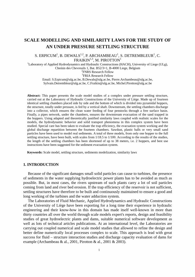
is made up of fourteen identical settling chambers 17 meters wide, 12 meters high and 200 meters long placed side by side and working totaly under pressure, and is supplied by a vertical shaft 12 meters wide and 277 meters long. All the chambers discharge through a control section into a collecting chamber, which ensures the clean water feeding of four penstocks downstream of a free surface basin (See fig. 1). The bottom of each settling chamber is subdivided into pyramidal hoppers 17 meters x 19 meters at the top and 3 meters x 3 meters at the bottom. A collector network, under the chambers, ensures the downstream evacuation of the sand trapped in the hoppers.
Fig. 1 Principle diagram of the projected settling structure For the equipment discharge of 784 m³/s, the flow velocity in each chamber is more or less
0.3 m/s and the theoretical cut off diameter for suspended particles is 250 µm.
3. SCALE MODELS CHARACTERISTICS The goals of the studies on scale models were to confirm the trap efficiency of a settling
chamber at the equipment discharge, to validate the sediments evacuation system at the bottom of the hoppers and to estimate the time and water volume necessary to the cleaning of a chamber, the silting up of which has reached a critical height. Due to the diversity of the phenomena to be studied and of the physical processes involved, three physical scale models have been build.
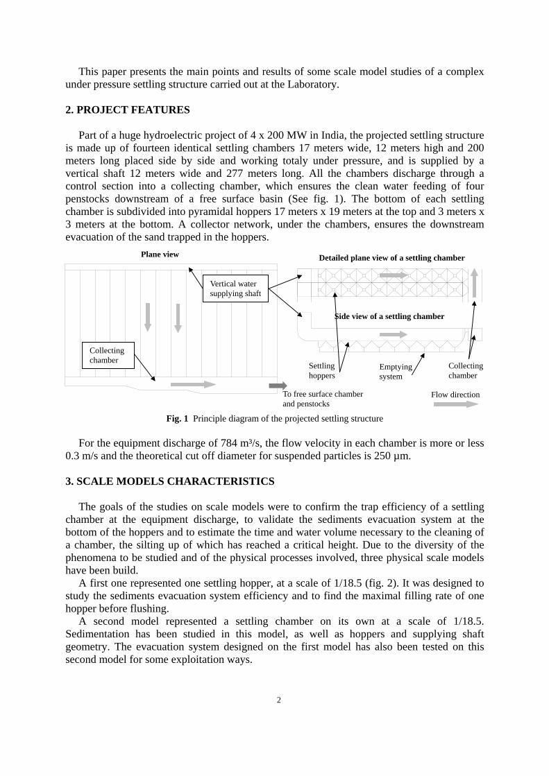
A first one represented one settling hopper, at a scale of 1/18.5 (fig. 2). It was designed to study the sediments evacuation system efficiency and to find the maximal filling rate of one hopper before flushing.
A second model represented a settling chamber on its own at a scale of 1/18.5. Sedimentation has been studied in this model, as well as hoppers and supplying shaft geometry. The evacuation system designed on the first model has also been tested on this second model for some exploitation ways.
Plane view Detailed plane view of a settling chamber
Side view of a settling chamber
Vertical water supplying shaft
Collecting chamber
Flow direction
Collecting chamber
Settling hoppers
Emptying system
To free surface chamber and penstocks
3
Finally, the full settling structure has been represented at a scale of 1/100 in order to analyse the whole hydraulic behaviour of the dam complex and more specifically the discharge repartition between the chambers and inertia effects in the system following a sudden closure of the turbines.
The choice of all the different length scales resulted of impositions of measurements accuracy, elimination of disruptive scale effects which could make the similarity imperfect as well as the bulk of the models. Special cares have been taken to find suitable materials to represent real sediments, as a function of the phenomenon to be analyzed in each model. In particular, similarity laws have been carefully studied.
4. SIMILARITY LAWS
4.1. Hydrodynamic similarity As the flows studied were mainly controlled by
gravity and as the friction forces could be supposed negligible, the studies were realized with the same ratio between inertia and gravity forces as on the prototype. This similarity results in the conservation between model and prototype of the non-dimensional number of Froude which leads to the following relation setting the velocity scale V* when the geometric length scale L* is chosen :
* *1m m m
r r r
Fr u hV LFr u h
= ⇒ = = = (1)
where m subscripts refer to scale model characteristics, r subscripts refer to the real model (prototype) characteristics, u is the flow velocity, h is the water depth.
The only hypothesis made at this stage is the conservation of the gravity acceleration g. The discharge scale Q* and the time scale T* can be obtain from relation (1) :
5** * *2 2Q V L L= = (2) *
* **
LT LV
= = (3)
4.2. Sediments similarity Entrainment phenomena
For the study of the emptying of one hopper, and to model sediments entrainment phenomena in general, it is very important to respect the length scale when choosing the size of the solid particles, and this in order to avoid all undesirable effect of mechanical obstruction of the system studied. Therefore, the scale of the particles dimension d* is given by :
*m
r
d Ld
= (4)
Fig. 2 Scale model of one hopper
Hopper and flushing system
4
Moreover, the conservation of the non-dimensional ratio between carrying and resisting forces was imposed to well represent sediments state. The carrying force exerted on particles with a diameter d in a liquid of density γe moving with a velocity u can be given by the law of Flamant (Campus, 1960) :
2 2
8e
ek d uF
gγ π= where k is a particles shape dependant factor (5)
The resistance force of the motionless sediments is a function of their weight and is given by (Campus, 1960) :
( )3
6s ed
Pπ γ γ−
= where γs is the density of the sediments (6)
The conservation of the ratio between these two forces, by taking into account (4), leads to the following scale for relative specific gravity ρ of the sediments, if it is assumed that the real and on model materials have the same shape characteristics :
( )*
* **2 1s e
du
γ γ− = = * 1ρ∆ = (7)
According to these similarity laws, silt, i.e. particles with diameter from 7 to 120 µm, have been used in the scale model to represent the sand treated in the prototype, i.e. particles with diameter from 125 µm to 2 mm, when entrainment effects had to be studied.
As regards to the cohesion of the sediments, the last phenomenon to consider in this first model, it seems to be overvalued on the model in comparison with the prototype. Indeed, the dimensions of the sediments are greatly reduced on the model compared with prototype, and adsorption effects (capillary tensions) and electrostatic surface tensions are then increased though the particles used on the model are of the same nature than the ones on the prototype. Sedimentation effects
On another hand, the sedimentation of particles in suspension in a liquid is a function of the value of the particles carrying velocity, considered equal to the flow velocity u, and of the particles fall velocity vs , given by the Stokes law (Carlier, 1972) :
43s
D f
d gvC
ρρ∆= (8)
where d is the diameter of the grains in suspension, g is the gravity acceleration, ∆ρ = ρsolid−ρfluid is the relative specific gravity of solid particles, CD is the particles drag coefficient, a function of their Reynolds number, ρf is the specific gravity of the fluid.
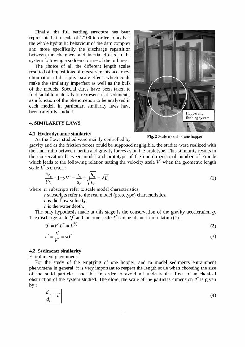
In a diagram, the sedimentation effect can be represented like :
Fig. 2 Diagram of the main effects existing in the phenomenon of sedimentation
Resultant
Carrying by the fluid (flow)
Sedimentation velocity
Resulting movement of the particle
Drag and Archimedes pressure
Gravity

5
As flows with sedimentation effects in a preferentially vertical level have to be studied, the conservation of the non-dimensional numbers of Froude and of the ratio between flow and sedimentation velocities have been forced. Thus, on a first approach, it has been imposed to the scale model to work in a horizontal hydrodynamic fluid – sedimentary interaction in the same way on the model and in the reality :
*1
sm
m sm m
sr sr r
r
vu v u Lv v uu
= ⇒ = = (9)
where the settling velocity is evaluated with the Stokes law (8). By expressing in the Stokes relation the drag coefficient for the model and the reality, we
have at our disposal an additional degree of freedom which has been used to force the conservation of the sediments drag coefficient :
,
,
,,
Re1 1
Re
f m m m
p mDm m
f r r rDr p r
r
u dC µ
u dCµ
ρ
ρ÷ = ⇒ = (10)
Now, the fluid specific gravity ρf and its dynamic viscosity µ are similar, as water is used both for the scale model and the prototype. (10) leads then to the following relation :
*
1m mr
r m r
d dud u d L
= ⇒ = (11)
By introducing in (8) the expression (9) of the sedimentation velocity, there is 2
, *
*,
1f rsm m m mDr
sr r Dm r f m r
v d C Lv d C L
ρρ ρρ ρ ρ
⎛ ⎞ ∆ ∆= ⇒ =⎜ ⎟ ∆ ∆⎝ ⎠ (12)
and so 3/ 2*m
r
Lρρ
∆ =∆
(13)
Calibrated sawdust saturated with water has been used to model the sediments. Due to their physical nature, these materials are not subject to surface tensions phenomena as strong as the ones observed for example with plastic particles. After 48 hours in water, sawdust density is constant and in good adequation with the needed value from similarity laws developed hereabove.
5. RESULTS
5.1 Model of one hopper From the initial state of a hopper filled with a certain amount of sediments and without
flow in the chamber axis, the sediments flushing system has been tested on this first model: the gates of the emptying pipes were opened and the time to empty one hopper has been measured as well as the shape and volume of the residual deposits.
Due to pipes blocking risks and sediments deposits consolidation phenomena, a small but permanent discharge in the emptying system appeared necessary. Moreover, it seemed preferable, whatever the adopted solution, to avoid all pipes sections other than vertical between the bottom of the hopper and the principal collector, with a system of flushing short and of large diameter. If an intermittent flushing system is planed, the emptying operations
6
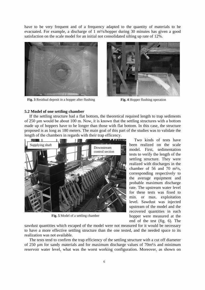
have to be very frequent and of a frequency adapted to the quantity of materials to be evacuated. For example, a discharge of 1 m³/s/hopper during 30 minutes has given a good satisfaction on the scale model for an initial not consolidated silting up rate of 12%.
5.2 Model of one settling chamber If the settling structure had a flat bottom, the theoretical required length to trap sediments
of 250 µm would be about 100 m. Now, it is known that the settling structures with a bottom made up of hoppers have to be longer than those with flat bottom. In this case, the structure proposed is as long as 180 meters. The main goal of this part of the studies was to validate the length of the chambers in regards with their trap efficency.
Two kinds of tests have been realized on the scale model. First, sedimentation tests to verify the length of the settling structure. They were realized with discharges in the chamber of 56 and 70 m³/s, corresponding respectively to the average equipment and probable maximum discharge rate. The upstream water level for these tests was fixed to min. or max. exploitation level. Sawdust was injected upstream of the model and the recovered quantities in each hopper were measured at the end of the test (fig. 6). The
sawdust quantities which escaped of the model were not measured for it would be necessary to have a more effective settling structure than the one tested, and the needed space to its realization was not available.
The tests tend to confirm the trap efficiency of the settling structure with a cut off diameter of 250 µm for sandy materials and for maximum discharge values of 70m³/s and minimum reservoir water level, what was the worst working configuration. Moreover, as shown on
Fig. 5 Model of a settling chamber
Supplying shaft Downstream control section
Fig. 3 Residual deposit in a hopper after flushing Fig. 4 Hopper flushing operation
7
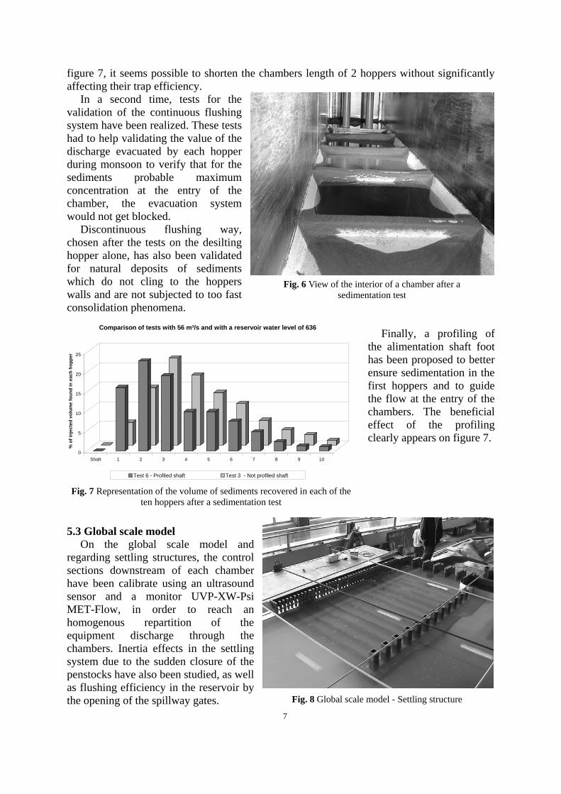
figure 7, it seems possible to shorten the chambers length of 2 hoppers without significantly affecting their trap efficiency.
In a second time, tests for the validation of the continuous flushing system have been realized. These tests had to help validating the value of the discharge evacuated by each hopper during monsoon to verify that for the sediments probable maximum concentration at the entry of the chamber, the evacuation system would not get blocked.
Discontinuous flushing way, chosen after the tests on the desilting hopper alone, has also been validated for natural deposits of sediments which do not cling to the hoppers walls and are not subjected to too fast consolidation phenomena.
Finally, a profiling of
the alimentation shaft foot has been proposed to better ensure sedimentation in the first hoppers and to guide the flow at the entry of the chambers. The beneficial effect of the profiling clearly appears on figure 7.
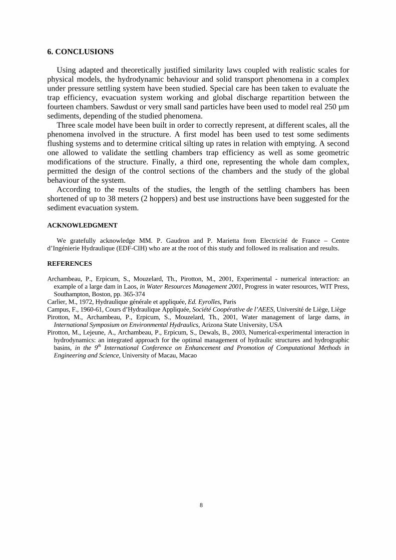
5.3 Global scale model On the global scale model and
regarding settling structures, the control sections downstream of each chamber have been calibrate using an ultrasound sensor and a monitor UVP-XW-Psi MET-Flow, in order to reach an homogenous repartition of the equipment discharge through the chambers. Inertia effects in the settling system due to the sudden closure of the penstocks have also been studied, as well as flushing efficiency in the reservoir by the opening of the spillway gates.
0
5
10
15
20
25
% o
f inj
ecte
d vo
lum
e fo
und
in e
ach
hopp
er
Shaft 1 2 3 4 5 6 7 8 9 10
Comparison of tests with 56 m³/s and with a reservoir water level of 636
Test 6 - Profiled shaft Test 3 - Not profiled shaft
Fig. 7 Representation of the volume of sediments recovered in each of the ten hoppers after a sedimentation test
Fig. 6 View of the interior of a chamber after a sedimentation test
Fig. 8 Global scale model - Settling structure
8
6. CONCLUSIONS Using adapted and theoretically justified similarity laws coupled with realistic scales for
physical models, the hydrodynamic behaviour and solid transport phenomena in a complex under pressure settling system have been studied. Special care has been taken to evaluate the trap efficiency, evacuation system working and global discharge repartition between the fourteen chambers. Sawdust or very small sand particles have been used to model real 250 µm sediments, depending of the studied phenomena.
Three scale model have been built in order to correctly represent, at different scales, all the phenomena involved in the structure. A first model has been used to test some sediments flushing systems and to determine critical silting up rates in relation with emptying. A second one allowed to validate the settling chambers trap efficiency as well as some geometric modifications of the structure. Finally, a third one, representing the whole dam complex, permitted the design of the control sections of the chambers and the study of the global behaviour of the system.
According to the results of the studies, the length of the settling chambers has been shortened of up to 38 meters (2 hoppers) and best use instructions have been suggested for the sediment evacuation system.
ACKNOWLEDGMENT
We gratefully acknowledge MM. P. Gaudron and P. Marietta from Electricité de France – Centre d’Ingénierie Hydraulique (EDF-CIH) who are at the root of this study and followed its realisation and results. REFERENCES Archambeau, P., Erpicum, S., Mouzelard, Th., Pirotton, M., 2001, Experimental - numerical interaction: an
example of a large dam in Laos, in Water Resources Management 2001, Progress in water resources, WIT Press, Southampton, Boston, pp. 365-374
Carlier, M., 1972, Hydraulique générale et appliquée, Ed. Eyrolles, Paris Campus, F., 1960-61, Cours d’Hydraulique Appliquée, Société Coopérative de l’AEES, Université de Liège, Liège Pirotton, M., Archambeau, P., Erpicum, S., Mouzelard, Th., 2001, Water management of large dams, in
International Symposium on Environmental Hydraulics, Arizona State University, USA Pirotton, M., Lejeune, A., Archambeau, P., Erpicum, S., Dewals, B., 2003, Numerical-experimental interaction in
hydrodynamics: an integrated approach for the optimal management of hydraulic structures and hydrographic basins, in the 9th International Conference on Enhancement and Promotion of Computational Methods in Engineering and Science, University of Macau, Macao