Embed Size (px)
Citation preview

SIMATIC NET
Industrial Ethernet switchesSCALANCE XM-400/XR-500 Web Based Management (WBM)
Configuration Manual
05/2017C79000-G8976-C248-12
Introduction 1
Description 2
IP addresses 3
Technical basics 4Configuring with Web Based Management 5
Troubleshooting/FAQ 6
Appendix A A

Legal informationWarning notice system
This manual contains notices you have to observe in order to ensure your personal safety, as well as to prevent damage to property. The notices referring to your personal safety are highlighted in the manual by a safety alert symbol, notices referring only to property damage have no safety alert symbol. These notices shown below are graded according to the degree of danger.
DANGERindicates that death or severe personal injury will result if proper precautions are not taken.
WARNINGindicates that death or severe personal injury may result if proper precautions are not taken.
CAUTIONindicates that minor personal injury can result if proper precautions are not taken.
NOTICEindicates that property damage can result if proper precautions are not taken.If more than one degree of danger is present, the warning notice representing the highest degree of danger will be used. A notice warning of injury to persons with a safety alert symbol may also include a warning relating to property damage.
Qualified PersonnelThe product/system described in this documentation may be operated only by personnel qualified for the specific task in accordance with the relevant documentation, in particular its warning notices and safety instructions. Qualified personnel are those who, based on their training and experience, are capable of identifying risks and avoiding potential hazards when working with these products/systems.
Proper use of Siemens productsNote the following:
WARNINGSiemens products may only be used for the applications described in the catalog and in the relevant technical documentation. If products and components from other manufacturers are used, these must be recommended or approved by Siemens. Proper transport, storage, installation, assembly, commissioning, operation and maintenance are required to ensure that the products operate safely and without any problems. The permissible ambient conditions must be complied with. The information in the relevant documentation must be observed.
TrademarksAll names identified by ® are registered trademarks of Siemens AG. The remaining trademarks in this publication may be trademarks whose use by third parties for their own purposes could violate the rights of the owner.
Disclaimer of LiabilityWe have reviewed the contents of this publication to ensure consistency with the hardware and software described. Since variance cannot be precluded entirely, we cannot guarantee full consistency. However, the information in this publication is reviewed regularly and any necessary corrections are included in subsequent editions.
Siemens AGDivision Process Industries and DrivesPostfach 48 4890026 NÜRNBERGGERMANY
C79000-G8976-C248-12Ⓟ 05/2017 Subject to change
Copyright © Siemens AG 2011 - 2017.All rights reserved

Table of contents
1 Introduction.................................................................................................................................................11
1.1 Information on this configuration manual...............................................................................11
2 Description..................................................................................................................................................15
2.1 Product characteristics...........................................................................................................15
2.2 Requirements for installation and operation...........................................................................17
2.3 C-PLUG / KEY-PLUG............................................................................................................17
2.4 Power over Ethernet (PoE)....................................................................................................18
3 IP addresses...............................................................................................................................................21
3.1 IPv4 / IPv6..............................................................................................................................21
3.2 IPv4 address..........................................................................................................................233.2.1 Structure of an IPv4 address..................................................................................................233.2.2 Initial assignment of an IPv4 address....................................................................................243.2.3 Address assignment with DHCP............................................................................................25
3.3 IPv6 addresses......................................................................................................................263.3.1 IPv6 terms..............................................................................................................................263.3.2 Structure of an IPv6 address..................................................................................................28
4 Technical basics.........................................................................................................................................31
4.1 Configuration limits.................................................................................................................31
4.2 SNMP.....................................................................................................................................35
4.3 RCDP.....................................................................................................................................37
4.4 VLAN......................................................................................................................................374.4.1 Basics.....................................................................................................................................374.4.2 VLAN tagging.........................................................................................................................384.4.3 Private VLAN..........................................................................................................................404.4.4 VLAN tunnel...........................................................................................................................42
4.5 Mirroring.................................................................................................................................43
4.6 Redundancy mechanism........................................................................................................444.6.1 Spanning Tree........................................................................................................................444.6.1.1 RSTP, MSTP, CIST...............................................................................................................454.6.2 HRP........................................................................................................................................464.6.3 MRP.......................................................................................................................................474.6.3.1 MRP - Media Redundancy Protocol ......................................................................................474.6.3.2 Configuration in WBM............................................................................................................504.6.3.3 Configuration in STEP 7.........................................................................................................504.6.4 Standby..................................................................................................................................554.6.5 Link Check.............................................................................................................................56
4.7 Link aggregation.....................................................................................................................57
SCALANCE XM-400/XR-500 Web Based Management (WBM)Configuration Manual, 05/2017, C79000-G8976-C248-12 3
4.8 Routing function.....................................................................................................................584.8.1 Static routing..........................................................................................................................584.8.2 VRRP.....................................................................................................................................594.8.2.1 VRRPv2.................................................................................................................................594.8.2.2 VRRP3...................................................................................................................................594.8.3 OSPF.....................................................................................................................................604.8.3.1 OSPFv2..................................................................................................................................604.8.3.2 OSPFv3..................................................................................................................................644.8.4 RIP.........................................................................................................................................654.8.4.1 RIPv2.....................................................................................................................................654.8.4.2 RIPng.....................................................................................................................................664.8.5 PIM.........................................................................................................................................66
4.9 NAT/NAPT.............................................................................................................................68
5 Configuring with Web Based Management................................................................................................73
5.1 Web Based Management.......................................................................................................73
5.2 Login......................................................................................................................................74
5.3 The "Information" menu.........................................................................................................785.3.1 Start page...............................................................................................................................785.3.2 Versions.................................................................................................................................835.3.3 Identification & Maintenance..................................................................................................845.3.4 ARP / Neighbors....................................................................................................................865.3.4.1 ARP Table..............................................................................................................................865.3.4.2 IPv6 Neighbor Table..............................................................................................................875.3.5 Log Table...............................................................................................................................875.3.6 Faults.....................................................................................................................................895.3.7 Redundancy...........................................................................................................................915.3.7.1 Spanning Tree........................................................................................................................915.3.7.2 VRRP statistics......................................................................................................................945.3.7.3 VRRP Statistics......................................................................................................................965.3.7.4 Ring redundancy....................................................................................................................985.3.7.5 Standby................................................................................................................................1005.3.7.6 Link Check...........................................................................................................................1015.3.8 Ethernet Statistics................................................................................................................1035.3.8.1 Interface Statistics................................................................................................................1035.3.8.2 Packet Size..........................................................................................................................1045.3.8.3 Packet Type.........................................................................................................................1055.3.8.4 Packet Error.........................................................................................................................1065.3.8.5 History..................................................................................................................................1085.3.9 Unicast.................................................................................................................................1095.3.10 Multicast...............................................................................................................................1105.3.10.1 Multicast...............................................................................................................................1105.3.10.2 IGMP Groups.......................................................................................................................1125.3.11 LLDP....................................................................................................................................1135.3.12 Fiber Monitoring Protocol.....................................................................................................1145.3.13 IPv4 routing..........................................................................................................................1165.3.13.1 Routing Table.......................................................................................................................1165.3.13.2 OSPFv2 Interfaces...............................................................................................................1175.3.13.3 OSPFv2 Neighbors..............................................................................................................1185.3.13.4 OSPFv2 Virtual Neighbors...................................................................................................120
Table of contents
SCALANCE XM-400/XR-500 Web Based Management (WBM)4 Configuration Manual, 05/2017, C79000-G8976-C248-12

5.3.13.5 OSPFv2 LSDB.....................................................................................................................1225.3.13.6 RIPv2 Statistics....................................................................................................................1235.3.13.7 NAT Translations.................................................................................................................1245.3.13.8 PIM interfaces......................................................................................................................1255.3.13.9 PIM Neighbors.....................................................................................................................1265.3.13.10 PIM Routes..........................................................................................................................1275.3.13.11 PIM RPs...............................................................................................................................1285.3.13.12 PIM BSRs.............................................................................................................................1295.3.13.13 MSDP Cache.......................................................................................................................1305.3.14 IPv6 routing..........................................................................................................................1315.3.14.1 IPv6 Routing Table..............................................................................................................1315.3.14.2 OSPFv3 Interfaces...............................................................................................................1325.3.14.3 OSPFv3 Neighbors..............................................................................................................1335.3.14.4 OSPFv3 Virtual Neighbors...................................................................................................1355.3.14.5 OSPFv3 AS-Scope LSDB....................................................................................................1365.3.14.6 OSPFv3 Area-Scope LSDB.................................................................................................1375.3.14.7 OSPFv3 Link-Scope LSDB..................................................................................................1395.3.14.8 RIPng Statistics....................................................................................................................1405.3.15 DHCP Server.......................................................................................................................1415.3.16 SNMP...................................................................................................................................1435.3.17 Security................................................................................................................................1435.3.17.1 Overview..............................................................................................................................1435.3.17.2 Supported Function Rights...................................................................................................1465.3.17.3 Roles....................................................................................................................................1475.3.17.4 Groups.................................................................................................................................148
5.4 The "System" menu.............................................................................................................1485.4.1 Configuration........................................................................................................................1485.4.2 General................................................................................................................................1525.4.2.1 Device..................................................................................................................................1525.4.2.2 Coordinates..........................................................................................................................1535.4.3 Agent IP...............................................................................................................................1545.4.4 DNS......................................................................................................................................1545.4.5 Restart..................................................................................................................................1565.4.6 Load & Save.........................................................................................................................1585.4.6.1 HTTP....................................................................................................................................1595.4.6.2 TFTP....................................................................................................................................1625.4.6.3 Passwords............................................................................................................................1665.4.7 Events..................................................................................................................................1675.4.7.1 Configuration........................................................................................................................1675.4.7.2 Severity Filters.....................................................................................................................1705.4.8 SMTP client..........................................................................................................................1715.4.9 DHCP...................................................................................................................................1735.4.9.1 DHCP Client.........................................................................................................................1735.4.9.2 DHCP Server.......................................................................................................................1745.4.9.3 Port-IP Address Mapping.....................................................................................................1785.4.9.4 Port Range...........................................................................................................................1795.4.9.5 DHCP Options......................................................................................................................1805.4.9.6 Relay Agent Information.......................................................................................................1835.4.9.7 Static Leases........................................................................................................................1845.4.10 SNMP...................................................................................................................................1865.4.10.1 General................................................................................................................................1865.4.10.2 Traps....................................................................................................................................189
Table of contents
SCALANCE XM-400/XR-500 Web Based Management (WBM)Configuration Manual, 05/2017, C79000-G8976-C248-12 5
5.4.10.3 v3 Groups.............................................................................................................................1905.4.10.4 v3 Users...............................................................................................................................1925.4.11 System Time........................................................................................................................1945.4.11.1 Manual Setting.....................................................................................................................1955.4.11.2 DST Overview......................................................................................................................1975.4.11.3 DST Configuration................................................................................................................1995.4.11.4 SNTP Client.........................................................................................................................2025.4.11.5 NTP Client............................................................................................................................2055.4.11.6 SIMATIC time client.............................................................................................................2075.4.11.7 PTP Client............................................................................................................................2085.4.12 Automatic logout..................................................................................................................2105.4.13 Configuration of the SELECT/SET button............................................................................2105.4.14 Syslog Client........................................................................................................................2125.4.15 Ports.....................................................................................................................................2145.4.15.1 Overview..............................................................................................................................2145.4.15.2 Configuration........................................................................................................................2175.4.16 Fault Monitoring...................................................................................................................2225.4.16.1 Power Supply.......................................................................................................................2225.4.16.2 Link Change.........................................................................................................................2235.4.16.3 Redundancy.........................................................................................................................2255.4.17 PROFINET...........................................................................................................................2255.4.18 EtherNet/IP...........................................................................................................................2275.4.19 PLUG...................................................................................................................................2285.4.19.1 Configuration........................................................................................................................2285.4.19.2 License.................................................................................................................................2325.4.20 Ping......................................................................................................................................2345.4.21 PoE......................................................................................................................................2355.4.21.1 General................................................................................................................................2355.4.21.2 Port.......................................................................................................................................2385.4.22 Port Diagnostics...................................................................................................................2405.4.22.1 Cable Tester.........................................................................................................................2405.4.22.2 SFP diagnostics...................................................................................................................2425.4.23 Configuration Backup...........................................................................................................243
5.5 The "Layer 2" menu.............................................................................................................2455.5.1 Configuration........................................................................................................................2455.5.2 QoS......................................................................................................................................2495.5.2.1 CoS queue mapping............................................................................................................2495.5.2.2 DSCP Mapping....................................................................................................................2515.5.2.3 QoS Trust.............................................................................................................................2525.5.3 Rate Control.........................................................................................................................2545.5.4 VLAN....................................................................................................................................2565.5.4.1 General................................................................................................................................2565.5.4.2 GVRP...................................................................................................................................2595.5.4.3 Port-based VLAN.................................................................................................................2615.5.4.4 Protocol-based VLAN group................................................................................................2635.5.4.5 Protocol-based VLAN port...................................................................................................2645.5.4.6 IPv4 subnet-based VLAN.....................................................................................................2665.5.4.7 IPv6 prefix-based VLAN.......................................................................................................2675.5.5 Private VLAN........................................................................................................................2695.5.5.1 General................................................................................................................................2695.5.5.2 IP Interface Mapping............................................................................................................2705.5.6 Provider bridge.....................................................................................................................272
Table of contents
SCALANCE XM-400/XR-500 Web Based Management (WBM)6 Configuration Manual, 05/2017, C79000-G8976-C248-12

5.5.6.1 Tunnel ports.........................................................................................................................2725.5.7 Mirroring...............................................................................................................................2745.5.7.1 General................................................................................................................................2745.5.7.2 Port.......................................................................................................................................2795.5.7.3 VLAN....................................................................................................................................2805.5.7.4 MAC Flow.............................................................................................................................2815.5.7.5 IP Flow.................................................................................................................................2825.5.8 Dynamic MAC Aging............................................................................................................2835.5.9 Ring redundancy..................................................................................................................2845.5.9.1 Ring......................................................................................................................................2845.5.9.2 Standby................................................................................................................................2875.5.9.3 Link Check...........................................................................................................................2905.5.10 Spanning tree.......................................................................................................................2925.5.10.1 General................................................................................................................................2925.5.10.2 CIST General.......................................................................................................................2935.5.10.3 CIST Port.............................................................................................................................2955.5.10.4 MST General........................................................................................................................3005.5.10.5 MST Port..............................................................................................................................3015.5.10.6 Enhanced Passive Listening Compatibility..........................................................................3035.5.11 Loop Detection.....................................................................................................................3045.5.12 Link aggregation...................................................................................................................3075.5.13 DCP forwarding....................................................................................................................3105.5.14 LLDP....................................................................................................................................3125.5.15 Fiber Monitoring Protocol.....................................................................................................3135.5.16 Unicast.................................................................................................................................3155.5.16.1 Filtering................................................................................................................................3155.5.16.2 Locked Ports........................................................................................................................3175.5.16.3 Learning...............................................................................................................................3195.5.16.4 Blocking................................................................................................................................3205.5.17 Multicast...............................................................................................................................3215.5.17.1 Groups.................................................................................................................................3215.5.17.2 IGMP snooping....................................................................................................................3245.5.17.3 GMRP..................................................................................................................................3255.5.17.4 Multicast blocking.................................................................................................................3275.5.17.5 MLD (IPv6)...........................................................................................................................3285.5.18 Broadcast.............................................................................................................................3305.5.19 PTP......................................................................................................................................3325.5.19.1 General................................................................................................................................3325.5.19.2 TC General...........................................................................................................................3335.5.19.3 TC Port.................................................................................................................................3345.5.20 RMON..................................................................................................................................3355.5.20.1 Statistics...............................................................................................................................3355.5.20.2 History..................................................................................................................................337
5.6 The "Layer 3 (IPv4)" menu...................................................................................................3395.6.1 Configuration........................................................................................................................3395.6.2 Subnets................................................................................................................................3405.6.2.1 Overview..............................................................................................................................3405.6.2.2 Configuration........................................................................................................................3435.6.3 NAT......................................................................................................................................3455.6.3.1 NAT......................................................................................................................................3455.6.3.2 Static....................................................................................................................................3475.6.3.3 Pool......................................................................................................................................348
Table of contents
SCALANCE XM-400/XR-500 Web Based Management (WBM)Configuration Manual, 05/2017, C79000-G8976-C248-12 7

5.6.3.4 NAPT....................................................................................................................................3495.6.4 Static Routes........................................................................................................................3515.6.5 Route Maps..........................................................................................................................3535.6.5.1 General................................................................................................................................3535.6.5.2 Interface & Value Match.......................................................................................................3545.6.5.3 Destination Match................................................................................................................3565.6.5.4 Next Hop Match..................................................................................................................3575.6.5.5 Create..................................................................................................................................3585.6.6 DHCP Relay Agent..............................................................................................................3595.6.6.1 General................................................................................................................................3595.6.6.2 Option...................................................................................................................................3615.6.7 VRRP...................................................................................................................................3645.6.7.1 Router..................................................................................................................................3645.6.7.2 Configuration........................................................................................................................3675.6.7.3 Address overview.................................................................................................................3695.6.7.4 Address Configuration..........................................................................................................3695.6.7.5 Interface Tracking................................................................................................................3705.6.8 VRRPv3...............................................................................................................................3725.6.8.1 Router..................................................................................................................................3725.6.8.2 Configuration........................................................................................................................3755.6.8.3 Addresses Overview............................................................................................................3775.6.8.4 Addresses Configuration......................................................................................................3775.6.8.5 Interface Tracking................................................................................................................3785.6.9 OSPFv2................................................................................................................................3805.6.9.1 Configuration........................................................................................................................3805.6.9.2 Areas....................................................................................................................................3825.6.9.3 Area Range..........................................................................................................................3835.6.9.4 Interfaces.............................................................................................................................3855.6.9.5 Interface Authentication.......................................................................................................3875.6.9.6 Virtual Links..........................................................................................................................3885.6.9.7 Virtual Link Authentication....................................................................................................3915.6.10 RIPv2...................................................................................................................................3925.6.10.1 Configuration........................................................................................................................3925.6.10.2 Interfaces.............................................................................................................................3935.6.11 IGMP....................................................................................................................................3955.6.12 PIM.......................................................................................................................................3975.6.12.1 PIM.......................................................................................................................................3975.6.12.2 Interface...............................................................................................................................3975.6.12.3 RP Static..............................................................................................................................3985.6.12.4 RP Candidate.......................................................................................................................4005.6.13 MSDP...................................................................................................................................4015.6.13.1 MSDP...................................................................................................................................4015.6.13.2 Peer......................................................................................................................................403
5.7 The "Layer 3 (IPv6)" menu...................................................................................................4045.7.1 Configuration........................................................................................................................4045.7.2 Subnets................................................................................................................................4065.7.3 DHCPv6 client......................................................................................................................4085.7.3.1 DHCPv6 client......................................................................................................................4085.7.3.2 DHCPv6 PD Sub Client........................................................................................................4095.7.4 Static Routes........................................................................................................................4115.7.5 Route maps..........................................................................................................................4125.7.5.1 General................................................................................................................................412
Table of contents
SCALANCE XM-400/XR-500 Web Based Management (WBM)8 Configuration Manual, 05/2017, C79000-G8976-C248-12

5.7.5.2 Interface & Value Match.......................................................................................................4135.7.5.3 Destination Match...............................................................................................................4165.7.5.4 Next-Hop filtern....................................................................................................................4165.7.5.5 Einstellen..............................................................................................................................4175.7.6 DHCPv4 Relay Agent...........................................................................................................4195.7.6.1 Interfaces.............................................................................................................................4195.7.6.2 Server Addresses.................................................................................................................4205.7.6.3 Outgoing Interfaces..............................................................................................................4215.7.7 VRRPv3...............................................................................................................................4225.7.7.1 Routers.................................................................................................................................4225.7.7.2 Configuration........................................................................................................................4255.7.7.3 Addresses Overview............................................................................................................4275.7.7.4 Addresses Configuration......................................................................................................4285.7.7.5 Interface Tracking................................................................................................................4295.7.8 OSPFv3................................................................................................................................4305.7.8.1 Configuration........................................................................................................................4305.7.8.2 Areas....................................................................................................................................4325.7.8.3 Area......................................................................................................................................4345.7.8.4 Interfaces.............................................................................................................................4355.7.8.5 Virtual Links..........................................................................................................................4375.7.9 RIPng...................................................................................................................................4395.7.9.1 RIPng Configuration.............................................................................................................4395.7.9.2 RIPng interfaces...................................................................................................................440
5.8 The "Security" menu............................................................................................................4415.8.1 User management................................................................................................................4415.8.2 Users....................................................................................................................................4445.8.2.1 Local Users..........................................................................................................................4445.8.2.2 Roles....................................................................................................................................4475.8.2.3 Groups.................................................................................................................................4495.8.3 Passwords............................................................................................................................4515.8.3.1 Passwords............................................................................................................................4515.8.3.2 Options.................................................................................................................................4535.8.4 AAA......................................................................................................................................4535.8.4.1 General................................................................................................................................4535.8.4.2 RADIUS Client.....................................................................................................................4545.8.4.3 802.1x Authenticator............................................................................................................4585.8.5 MAC ACL.............................................................................................................................4635.8.5.1 Rules Configuration..............................................................................................................4635.8.5.2 Ingress Rules.......................................................................................................................4655.8.5.3 Egress Rules........................................................................................................................4675.8.6 IP ACL..................................................................................................................................4695.8.6.1 Rules Configuration..............................................................................................................4695.8.6.2 Protocol Configuration..........................................................................................................4705.8.6.3 Ingress Rules.......................................................................................................................4725.8.6.4 Egress Rules........................................................................................................................4755.8.7 Management ACL................................................................................................................477
6 Troubleshooting/FAQ...............................................................................................................................481
6.1 Firmware update - via WBM.................................................................................................481
6.2 Firmware update via WBM or CLI not possible....................................................................481
6.3 Message: SINEMA configuration not yet accepted..............................................................482
Table of contents
SCALANCE XM-400/XR-500 Web Based Management (WBM)Configuration Manual, 05/2017, C79000-G8976-C248-12 9

A Appendix A...............................................................................................................................................485
A.1 Supported RFCs..................................................................................................................485
Index.........................................................................................................................................................487
Table of contents
SCALANCE XM-400/XR-500 Web Based Management (WBM)10 Configuration Manual, 05/2017, C79000-G8976-C248-12

Introduction 11.1 Information on this configuration manual
Validity of the configuration manual This Configuration Manual covers the following products:
● SCALANCE XR-500
– SCALANCE XR524-8C
– SCALANCE XR526-8C
– SCALANCE XR528-6M
– SCALANCE XR552-12M
The devices are available with or without routing functions. The routing function can either be integrated in the devices or made available with a KEY-PLUG.
● SCALANCE XM-400
– SCALANCE XM408-4C
– SCALANCE XM408-8C
– SCALANCE XM416-4C
The devices are available with or without routing functions. The routing function can either be integrated in the devices or made available with a KEY-PLUG.
This Configuration Manual applies to the following software version:
● SCALANCE XR-500 firmware as of version 6.1
● SCALANCE XM-400 firmware as of version 6.1
Purpose of the Configuration ManualThis Configuration Manual is intended to provide you with the information you require to install, commission and operate IE switches. It provides you with the information you require to configure the IE switches.
SCALANCE XM-400/XR-500 Web Based Management (WBM)Configuration Manual, 05/2017, C79000-G8976-C248-12 11

Orientation in the documentationApart from this configuration manual, the products also have the following documentation:
● Configuration Manual:
– SCALANCE XM-400/XR-500 Command Line Interface (CLI)
This document contains the CLI commands that are supported by the IE switches SCALANCE XM-400 and SCALANCE XR-500.
● Operating instructions:
– SCALANCE XR-500
– MM900 media modules for SCALANCE XR-500M
– Fan unit FAN597-1 for SCALANCE XR-500M
– Power supply PS598-1 for SCALANCE XR-500M
– SCALANCE XM-400
– Extender for SCALANCE XM-400
– Pluggable transceiver SFP/SFP+/SCP/STP
– PoE power supply SCALANCE PS9230 PoE / SCALANCE PS924 PoE
These documents contain information on installing and connecting up and approvals for the products.
The following documentation is also available from SIMATIC NET on the topic of Industrial Ethernet:
● System manual "Industrial Ethernet / PROFINET"
● System manual "Industrial Ethernet / PROFINET - Passive network components"
All these documents are available on the SCALANCE X DVD.
Terms used
The designation . . . stands for . . .IE switch Industrial Ethernet switchIPv4 address IPv4 address IPv6 address IPv6 address IP address IPv4/IPv6 address IPv4 interface Interface that supports IPv4. IPv6 interface Interface that supports IPv6. The interface can have more than one IPv6
address The IPv6 addresses have different ranges (scope), e.g. link localIP interface Interface that supports both IPv4 and IPv6. As default the IPv4 support
is already activated. The IPv6 support needs to be activated extra.
Introduction1.1 Information on this configuration manual
SCALANCE XM-400/XR-500 Web Based Management (WBM)12 Configuration Manual, 05/2017, C79000-G8976-C248-12

What's new as of version 6.1?Below, you will find an overview of the most important function expansions:
● Information in the configuration limits
● RCDP
● DHCP
– Assignment of port to IP address
● Firmware on PLUG
● Configuration Backup
● IPv6 prefix-based VLAN
● Q-in-Q VLAN tunnel
● Link Check
● Loopback functionality
● PIM
– "Bidirectional multicast" functionality
● MSDP
Note
Default user "user" set in the factory
As of firmware version 6.0 the default user set in the factory "user" is no longer available when the product ships.
If you update a device to the firmware V6.0 the default user set in the factory "user" is initially still available. If you reset the device to the factory settings ("Restore Factory Defaults and Restart") the default user set in the factory "user" is deleted.
You can create new users with the role "user".
SIMATIC NET glossaryExplanations of many of the specialist terms used in this documentation can be found in the SIMATIC NET glossary.
You will find the SIMATIC NET glossary here:
● SIMATIC NET Manual Collection or product DVDThe DVD ships with certain SIMATIC NET products.
● On the Internet under the following address:50305045 (http://support.automation.siemens.com/WW/view/en/50305045)
Introduction1.1 Information on this configuration manual
SCALANCE XM-400/XR-500 Web Based Management (WBM)Configuration Manual, 05/2017, C79000-G8976-C248-12 13

Security informationSiemens provides products and solutions with industrial security functions that support the secure operation of plants, solutions, machines, equipment and/or networks. They are important components in a holistic industrial security concept. With this in mind, Siemens’ products and solutions undergo continuous development. Siemens recommends strongly that you regularly check for product updates.
For the secure operation of Siemens products and solutions, it is necessary to take suitable preventive action (e.g. cell protection concept) and integrate each component into a holistic, state-of-the-art industrial security concept. Third-party products that may be in use should also be considered. For more information about industrial security, visit http://www.siemens.com/industrialsecurity.
To stay informed about product updates as they occur, sign up for a product-specific newsletter. For more information, visit http://support.automation.siemens.com.
License conditions
NoteOpen source software
Read the license conditions for open source software carefully before using the product.
You will find license conditions in the following documents on the supplied data medium:
● DOC_OSS-SCALANCE-X_74.pdf
● DC_LicenseSummaryScalanceXM400_76.pdf
● DC_LicenseSummaryScalanceXR500_76.pdf
You will find these documents on the product DVD in the following directory: /Open Source Information
TrademarksThe following and possibly other names not identified by the registered trademark sign ® are registered trademarks of Siemens AG:
SIMATIC NET, SCALANCE, C-PLUG, OLM
FirmwareThe firmware is signed and encrypted. This ensures that only firmware created by Siemens can be downloaded to the device.
Introduction1.1 Information on this configuration manual
SCALANCE XM-400/XR-500 Web Based Management (WBM)14 Configuration Manual, 05/2017, C79000-G8976-C248-12
Description 22.1 Product characteristics
Properties of the IE switches● The Ethernet interfaces support the following modes:
– 10 Mbps and 100 Mbps both in full and half duplex
– 1000 Mbps full duplex
– Autocrossing
– Autopolarity
● Redundancy protocols Multiple Spanning Tree Protocol (MSTP), Rapid Spanning Tree Protocol (RSTP) and Spanning Tree Protocol (STP)This means part of a network can be connected redundantly to a higher-level company network. The reconfiguration time of the network is in the seconds range and therefore takes longer than the ring redundancy method.
● Virtual networks (VLAN)To structure Industrial Ethernet networks with a fast growing number of nodes, a physical network can be divided into several virtual subnets. Port-based, protocol-based and subnet-based VLANs are available.
● Load limitation when using multicast protocols, for example video transmissionBy learning the multicast sources and destinations (IGMP snooping, IGMP querier), the IE switches can filter multicast data traffic and limit the load in the network. Multicast and broadcast data traffic can be limited.
● Time-of-day synchronizationDiagnostics messages (log table entries, e-mails) are given a time stamp. The local time is uniform throughout the network thanks to synchronization with a SICLOCK time transmitter or SNTP/NTP/PTP server and therefore makes the identification of diagnostics messages of several devices easier.
● Link aggregation (IEEE 802.1AX) for bundling ports
● Quality of Service for classification of the network traffic is according to COS (Class of Service - IEEE 802.11Q) and DSCP (Differentiated Services Code Point - RFC 2474)
Layer 3 functionsThe following functions are only available on devices with routing functions:
● Static routing
● OSPF / OSPFv3
● VRRP / VRRPv3
● RIP / RIPng
SCALANCE XM-400/XR-500 Web Based Management (WBM)Configuration Manual, 05/2017, C79000-G8976-C248-12 15

● IGMP
● PIM
● MSDP
There are devices that natively support all routing functions. You will find the order numbers in the operating instructions of the devices.
On the devices that only support layer 2, you can enable the routing functions with a KEY-PLUG.
Naming interfacesInterface names with SCALANCE XM-400
● Interfaces of the basic deviceThe interfaces of the basic device SCALANCE XM-400 are called module 1.
● Interfaces of extendersThe port extenders are called module 2 and module 3 starting from the basic device. The number of port extenders depends on the number of ports of the basic device.The extender function is called module 0.
Interface names with SCALANCE XR-500
● Permanently integrated InterfacesThe interfaces permanently installed in the SCALANCE XR-500 are identified with module 0.
● Interfaces of modulesThe slots for modules are called module 1 followed by numbers. The numbering range depends on the hardware configuration. The numbering is fixed and does not depend on the number of modules being used.Each module has 4 ports numbered 1 to 4.
Combo portsCombo port is the name for two communication ports. A combo port has the two following plug-in options:
● a fixed RJ-45 port
● an SFP transceiver slot that can be equipped individually
Of these two ports, only one can ever be active.
You can set the active port on the WBM page "System > Ports > Configuration"with the CLI command media-type.
Description2.1 Product characteristics
SCALANCE XM-400/XR-500 Web Based Management (WBM)16 Configuration Manual, 05/2017, C79000-G8976-C248-12

2.2 Requirements for installation and operation
Requirements for installation and operation of the IE switches A PG/PC with a network connection must be available in order to configure the IE switches. If no DHCP server is available, a PG/PC on which the Primary Setup Tool (PST) is installed is necessary for the initial assignment of an IP address to the IE switches. For the other configuration settings, a PG/PC with Telnet or an Internet browser is necessary.
Serial interfaceThe IE switches have a serial interface. An IP address is unnecessary to be able to access the device via the serial interface. A serial cable ships with the products.
Set the following parameters for the connection:
● Bits per second: 115200
● Data bits: 8
● Parity: None
● Stop bits: 1
● Flow control: None
2.3 C-PLUG / KEY-PLUG
Configuration information on the C-PLUG / KEY-PLUG The C-PLUG / KEY-PLUG is used to transfer the configuration of the old device to the new device when a device is replaced.
NOTICE
Do not remove or insert a C-PLUG / KEY-PLUG during operation!
A C-PLUG / KEY-PLUG may only be removed or inserted when the device is turned off.The device regularly checks whether or not a KEY-PLUG is present. If it is detected that the KEY-PLUG was removed, there is a restart. If a valid KEY-PLUG was inserted in the device, the device changes to a defined error state following the restart.
When the new device starts up with the C-PLUG / KEY-PLUG, it then continues automatically with exactly the same configuration as the old device. One exception to this can be the IP configuration if it is set over DHCP and the DHCP server has not been reconfigured accordingly.
Description2.3 C-PLUG / KEY-PLUG
SCALANCE XM-400/XR-500 Web Based Management (WBM)Configuration Manual, 05/2017, C79000-G8976-C248-12 17

A reconfiguration is necessary if you use functions based on MAC addresses.
Note
In terms of the C-PLUG / KEY-PLUG, the SCALANCE devices work in two modes:● Without C-PLUG / KEY-PLUG
The device stores the configuration in internal memory. This mode is active when no C-PLUG / KEY-PLUG is inserted.
● With C-PLUG / KEY-PLUGThe configuration stored on the C-PLUG / KEY-PLUG is displayed over the user interfaces. If changes are made to the configuration, the device stores the configuration directly on the C-PLUG / KEY-PLUG and in the internal memory. This mode is active as soon as a C-PLUG / KEY-PLUG is inserted. When the device is started with a C-PLUG / KEY-PLUG inserted, the device starts up with the configuration data on the C-PLUG / KEY-PLUG.
NoteIncompatibility with previous versions with C-PLUG / KEY-PLUG inserted
During the installation of a previous version of the firmware, the configuration data can be lost. In this case, the device starts up with the factory settings after the firmware has been installed. In this situation, if a C-PLUG / KEY-PLUG is inserted in the device, following the restart, this has the status "Not Accepted" since the C-PLUG / KEY-PLUG still has the configuration data of the previous more up-to-date firmware. This allows you to return to the previous, more up-to-date firmware without any loss of configuration data. If the original configuration on the C-PLUG / KEY-PLUG is no longer required, the C-PLUG / KEY-PLUG can be deleted or rewritten manually.
License information on the KEY-PLUGIn addition to the configuration, the KEY-PLUG also contains a license that allows the use of layer 3 functions.
2.4 Power over Ethernet (PoE)
General"Power over Ethernet" (PoE) is a power supply technique for network components according to IEEE 802.3af or IEEE 802.3at. The power is supplied over the Ethernet cables that connect the individual network components together. This makes an additional power cable unnecessary. PoE can be used with all PoE-compliant network components that have a maximum power consumption of max. 25.50 W.
Description2.4 Power over Ethernet (PoE)
SCALANCE XM-400/XR-500 Web Based Management (WBM)18 Configuration Manual, 05/2017, C79000-G8976-C248-12

Cable used for the power supply● Alternative A (redundant wires)
In Fast Ethernet, the wire pairs 1, 2 and 3, 6 are used to transfer data. Pairs 4, 5 and 7, 8 are then used to supply power. If there are only four wires available, the voltage is modulated onto the wires 1, 2 and 3, 6 (see variant 2). This alternative is suitable for a data transmission rate of 10/100 Mbps. This type of power supply is not suitable for 1 Gbps since with gigabit all eight wires are used for data transfer.
● Alternative B (phantom power)With phantom power, the power is supplied over the pairs that are used for data transfer, in other words, all eight (1 Gbps) or four (10/100 Mbps) wires are used both for the data transfer and the power supply.
A PoE-compliant end device must support both alternative A and alternative B over redundant wires. A switch with PoE capability can supply the end device either using
● alternative A or
● Alternative B or
● alternative A and alternative B.
Note
The SCALANCE PE408PoE extender supports alternative B.
EndspanWith endspan, the power is supplied via a switch that can reach a device over an Ethernet cable. The switch must be capable of PoE, for example a SCALANCE X108PoE, SCALANCE X308-2M PoE, all SCALANCE XM400 switches with PE408PoE, SCALANCE XR552‑12M.
MidspanMidspan is used when the switch is not PoE-compliant. The power is supplied by an additional device between the switch and end device. In this case, only data rates of 10/100 Mbps can be achieved because the power is supplied on redundant wires.
A Siemens power insert can also be used as the interface for the power input. Since a power insert supports a power supply of 24 VDC, it does not conform with IEEE 802.3af or IEEE 802.3at. The following restrictions relating to the use of power inserts should be noted:
WARNING
Operate the power insert only when the following conditions apply:● with extra low voltages SELV, PELV complying with IEC 60364-4-41● in USA/CAN with power supplies complying with NEC class 2● in USA/CAN, the cabling must meet the requirements of NEC/CEC● Current load maximum 0.5 A
Description2.4 Power over Ethernet (PoE)
SCALANCE XM-400/XR-500 Web Based Management (WBM)Configuration Manual, 05/2017, C79000-G8976-C248-12 19
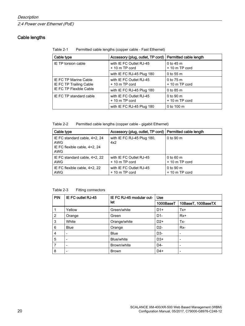
Cable lengths
Table 2-1 Permitted cable lengths (copper cable - Fast Ethernet)
Cable type Accessory (plug, outlet, TP cord) Permitted cable lengthIE TP torsion cable with IE FC Outlet RJ-45
+ 10 m TP cord0 to 45 m + 10 m TP cord
with IE FC RJ-45 Plug 180 0 to 55 mIE FC TP Marine CableIE FC TP Trailing CableIE FC TP Flexible Cable
with IE FC Outlet RJ-45 + 10 m TP cord
0 to 75 m + 10 m TP cord
with IE FC RJ-45 Plug 180 0 to 85 mIE FC TP standard cable with IE FC Outlet RJ-45
+ 10 m TP cord0 to 90 m + 10 m TP cord
with IE FC RJ-45 Plug 180 0 to 100 m
Table 2-2 Permitted cable lengths (copper cable - gigabit Ethernet)
Cable type Accessory (plug, outlet, TP cord) Permitted cable lengthIE FC standard cable, 4×2, 24 AWGIE FC flexible cable, 4×2, 24 AWG
with IE FC RJ-45 Plug 180,4x2
0 to 90 m
IE FC standard cable, 4×2, 22 AWG
with IE FC Outlet RJ-45 + 10 m TP cord
0 to 60 m + 10 m TP cord
IE FC flexible cable, 4×2, 22 AWG
with IE FC Outlet RJ-45 + 10 m TP cord
0 to 90 m + 10 m TP cord
Table 2-3 Fitting connectors
PIN IE FC outlet RJ-45 IE FC RJ-45 modular out‐let
Use1000BaseT 10BaseT, 100BaseTX
1 Yellow Green/white D1+ Tx+2 Orange Green D1- Rx+3 White Orange/white D2+ Tx-6 Blue Orange D2- Rx-4 - Blue D3- -5 - Blue/white D3+ -7 - Brown/white D4- -8 - Brown D4+ -
Description2.4 Power over Ethernet (PoE)
SCALANCE XM-400/XR-500 Web Based Management (WBM)20 Configuration Manual, 05/2017, C79000-G8976-C248-12

IP addresses 33.1 IPv4 / IPv6
What are the essential differences?
IPv4 IPv6IP configuration ● DHCP server
● Manual
● Stateless Address Autoconfiguration (SLAAC): Stateless autoconfiguration using NDP (Neighbor Discovery Protocol)– Creates a link local address for every interface that
does not require a router on the link.– Checks the uniqueness of the address on the link that
requires no router on the link.– Specifies whether the global addresses are obtained
via a status-free mechanism, a mechanism with status or via both mechanisms. (Requires a router on the link.)
● Manual● DHCPv6 (status dependent)
Available IP addresses 32-bit: 4, 29 * 109 address‐es
128-bit: 3, 4 * 1038 addresses
Address format Decimal: 192.168.1.1with port: 192.168.1.1:20
Hexadecimal: 2a00:ad80::0123with port: [2a00:ad80::0123]:20
Loopback 127.0.0.1 ::1IP addresses of the interface 4 IP addresses Multiple IP addresses
● LLA: A link local address (formed automatically) fe80::/128 per interface
● ULA: Several unique local unicast addresses per interface● GUA: Several global unicast addresses per interface
Header ● Checksum● Variable length● Fragmentation in the
header● No security
● Checking at a higher layer● Fixed size● Fragmentation in the extension header
Fragmentation Host and router Only endpoint of the communicationQuality of service Type of Service (ToS) for
prioritizationThe prioritization is specified in the header field "Traffic Class".
Types of frame Broadcast, multicast, uni‐cast
Multicast, unicast, anycast
SCALANCE XM-400/XR-500 Web Based Management (WBM)Configuration Manual, 05/2017, C79000-G8976-C248-12 21

IPv4 IPv6Identification of DHCP clients/server
Client ID:MAC address
DUID + IAID(s) = exactly one interface of the hostDUID = DHCP unique identifierIdentifies server and clients uniquely and should not change, not even when replacing network components!IAID = Identity Association IdentifierAt least one per interface is generated by the client and re‐mains unchanged when the DHCP client restartsThree methods of obtaining the DUID● DUID-LLT● DUID-EN● DUID-LL
DHCP via UDP with broadcast via UDP with unicast RFC 3315, RFC 3363Stateful DHCPv6 Status-dependent configuration in which the IPv6 address and the configuration settings are transferred. Four DHVPv6 messages are exchanged between client and server:1. SOLICIT:
Sent by the DHCPv6 client to localize DHCPv6 servers.2. ADVERTISE
The available DHCPv6 servers reply to this. 3. REQUEST
The DHCPv6 client requests an IPv6 address and the configuration settings from the DHCPv6 server.
4. REPLYThe DHCPv6 server sends the IPv6 address and the configuration settings.
If the client and server support the function "Rapid commit" the procedure is shortened to two DHCPv6 messages SOLICIT and REPLY .Stateless DHCPv6In stateless DHCPv6, only the configuration settings are trans‐ferred.Prefix delegationThe DHCPv6 server delegates the distribution of IPv6 prefixes to the DHCPv6 client. The DHCPv6 client is also known as PD router.
Resolution of IP addresses in hardware addresses
ARP (Address Resolution Protocol)
NDP (Neighbor Discovery Protocol)
IP addresses3.1 IPv4 / IPv6
SCALANCE XM-400/XR-500 Web Based Management (WBM)22 Configuration Manual, 05/2017, C79000-G8976-C248-12

3.2 IPv4 address
3.2.1 Structure of an IPv4 address
Address classes
IP address range Max. number of networks Max. number of hosts/net‐work
Class CIDR
1.x.x.x through 126.x.x.x 126 16777214 A /8128.0.x.x through 191.255.x.x 16383 65534 B /16192.0.0.x through 223.255.255.x 2097151 254 C /24224.0.0.0 - 239.255.255.255 Multicast applications D 240.0.0.0 - 255.255.255.255 Reserved for future applications E
An IP address consists of 4 bytes. Each byte is represented in decimal, with a dot separating it from the previous one. This results in the following structure, where XXX stands for a number between 0 and 255:
XXX.XXX.XXX.XXX
The IP address is made up of two parts, the network ID and the host ID. This allows different subnets to be created. Depending on the bytes of the IP address used as the network ID and those used for the host ID, the IP address can be assigned to a specific address class.
Subnet mask The bits of the host ID can be used to create subnets. The leading bits represent the address of the subnet and the remaining bits the address of the host in the subnet.
A subnet is defined by the subnet mask. The structure of the subnet mask corresponds to that of an IP address. If a "1" is used at a bit position in the subnet mask, the bit belongs to the corresponding position in the IP address of the subnet address, otherwise to the address of the computer.
Example of a class B network:
The standard subnet address for class B networks is 255.255.0.0; in other words, the last two bytes are available for defining a subnet. If 16 subnets must be defined, the third byte of the subnet address must be set to 11110000 (binary notation). In this case, this results in the subnet mask 255.255.240.0.
To find out whether two IP addresses belong to the same subnet, the two IP addresses and the subnet mask are ANDed bit by bit. If both logic operations have the save result, both IP addresses belong to the same subnet, for example, 141.120.246.210 and 141.120.252.108.
IP addresses3.2 IPv4 address
SCALANCE XM-400/XR-500 Web Based Management (WBM)Configuration Manual, 05/2017, C79000-G8976-C248-12 23

Outside the local area network, the distinction between network ID and host ID is of no significance, in this case packets are delivered based on the entire IP address.
Note
In the bit representation of the subnet mask, the "ones" must be set left-justified; in other words, there must be no "zeros" between the "ones".
3.2.2 Initial assignment of an IPv4 address
Configuration optionsAn initial IP address for an IE switch cannot be assigned using Web Based Management (WBM) because this configuration tool can only be used if an IP address already exists.
The following options are available to assign an IP address to an unconfigured device:
● DHCP (default)
● Primary Setup Tool (PST)
– To be able to assign an IP address to the IE switch with the PST, it must be possible to reach the device via Ethernet.
– You will find the PST on the Internet pages of Siemens Industry Online Support under the entry ID 19440762 (http://support.automation.siemens.com/WW/view/en/19440762).
– For further information about assigning the IP address with the PST, refer to the documentation "Primary Setup Tool (PST)".
● STEP7In STEP 7, you can configure the topology, the device name and the IP address. If you connect an unconfigured IE switch to the controller, the controller assigns the configured device name and the IP address to the IE switch automatically.
– STEP 7 as of V5.5 SP4For further information on the assignment of the IP address using STEP 7 refer to the documentation "Configuring Hardware and Connections with STEP 7", in the section "Steps For Configuring a PROFINET IO System".
– STEP 7 Basic as of V12 SP1 or STEP 7 Professional as of V12 SP1For further information on assigning the IP address using STEP 7 (as of V12 SP1), refer to the online help "Information system", section "Addressing PROFINET devices".
● CLI via the serial interfaceFor further information on assigning the IP address using the CLI, refer to the documentation "SCALANCE XM-400/XR-500 Command Line Interface".
IP addresses3.2 IPv4 address
SCALANCE XM-400/XR-500 Web Based Management (WBM)24 Configuration Manual, 05/2017, C79000-G8976-C248-12

● NCM PCFor further information on assigning the IP address using NCM PC, refer to the documentation "Commissioning PC stations - Manual and Quick Start", in the section "Creating a PROFINET IO system".
● RUGGEDCOM EXPLORERWith the RUGGEDCOM EXPLORER you can recognize devices in a network and make the following basic settings:
– IP Address
– Subnet Mask
– Default Gateway
– System Name
– Device Location
– System Contact
The RUGGEDCOM EXPLORER can run on every LAN-based MS Windows-PC.To be able to use the RUGGEDCOM EXPLORER, RCDP (RUGGEDCOM Discovery Protocol) must be enabled on the device.You will find more information on the RUGGEDCOM EXPLORER here:
– On the Internet pages of Siemens Industry Online Support (https://support.industry.siemens.com/cs/ww/en/ps/15391/man)
– On the Internet pages of RUGGEDCOM products (http://w3.siemens.com/mcms/industrial-communication/en/rugged-communication/produkte/software/Seiten/explorer.aspx)
Note
When the product ships and following "Restore Factory Defaults and Restart", DHCP is enabled. If a DHCP server is available in the local area network, and this responds to the DHCP request of an IE switch, the IP address, subnet mask and gateway are assigned automatically when the device first starts up.
3.2.3 Address assignment with DHCP
Properties of DHCPDHCP (Dynamic Host Configuration Protocol) is a method for automatic assignment of IP addresses. It has the following characteristics:
● DHCP can be used both when starting up a device and during ongoing operation.
● The assigned IP address remains valid only for a limited time known as the lease time. When half the period of validity has elapsed. the DHCP client can extend the period of the assigned IPv4 address. When the entire time has elapsed, the DHCP client needs to request a new IPv4 address.
IP addresses3.2 IPv4 address
SCALANCE XM-400/XR-500 Web Based Management (WBM)Configuration Manual, 05/2017, C79000-G8976-C248-12 25

● There is normally no fixed address assignment; in other words, when a client requests an IP address again, it normally receives a different address from the previous address. It is possible to configure the DHCP server so that the DHCP client always receives the same fixed address in response to its request. The parameter with which the DHCP client is identified for the fixed address assignment is set on the DHCP client. The address can be assigned via the MAC address, the DHCP client ID, PROFINET device name or the device name. You configure the parameter in "System > DHCP Client (Page 173)".
● The following DHCP options are supported:
– DHCP option 3: Assignment of a router address
– DHCP option 6: Assignment of a DNS server address
– DHCP option 66: Assignment of a dynamic TFTP server name
– DHCP option 67: Assignment of a dynamic boot file name
– DHCP option 82: Assignment of IP addresses depending on the device index, switch port, the VLAN ID or user-defined identification values of the DHCP relay agent.
Note
DHCP uses a mechanism with which the IP address is assigned for only a short time (lease time). If the device does not reach the DHCP server with a new request on expiry of the lease time, the assigned IP address, the subnet mask and the gateway continue to be used.
The device therefore remains accessible under the last assigned IP address even without a DHCP server. This is not the standard behavior of office devices but is necessary for problem-free operation of the plant.
3.3 IPv6 addresses
3.3.1 IPv6 termsNetwork node
A network node is a device that is connected to one or more networks via one or more interfaces.
Router
A network node that forwards IPv6 packets.
Host
A network node that represents an end point for IPv6 communication relations.
Link
A link is, according to IPv6 terminology, a direct layer 3 connection within an IPv6 network.
Neighbor
Two network nodes are called neighbors when they are located on the same link.
IPv6 interface
IP addresses3.3 IPv6 addresses
SCALANCE XM-400/XR-500 Web Based Management (WBM)26 Configuration Manual, 05/2017, C79000-G8976-C248-12

Physical or logical interface on which IPv6 is activated.
Path MTU
Maximum permitted packet size on a path from a sender to a recipient.
Path MTU discovery
Mechanism for determining the maximum permitted packet size along the entire path from a sender to a recipient.
LLA
Link local address FE80::/10
As soon as IPv6 is activated on the interface, a link local address is formed automatically. Can only be reached by nodes located on the same link.
ULA
Unique Local Address
Defined in RFC 4193. Via this address, the IPv6 interface can be reached in the LAN.
GUA
Global Unicast Address Via this address, the IPv6 interface can be reached, e.g. via the Internet.
Interface ID
The interface ID is formed with the EUI-64 method or manually.
EUI-64
Extended Unique Identifier (RFC 4291); method for forming the interface ID. In Ethernet, the interface ID is formed from the MAC address of the interface. Divides the MAC address into the manufacturer-specific part (OUI) and the network-specific part (NIC) and inserts FFFE between the two parts.
Example:
MAC address = AA:BB:CC:DD:EE:FF
OUI = AA:BB:CC
NIC = DD:EE:FF
EUI-64 = OUI + FFFE + NIC = AA:BB:CC:FF:FE:DD:EE:FF
Scope
Defines the range of the IPv6 address.
IP addresses3.3 IPv6 addresses
SCALANCE XM-400/XR-500 Web Based Management (WBM)Configuration Manual, 05/2017, C79000-G8976-C248-12 27

3.3.2 Structure of an IPv6 address
IPv6 address format - notationIPv6 addresses consist of 8 fields each with four-character hexadecimal numbers (128 bits in total). The fields are separated by a colon.
Example:
fd00:0000:0000:ffff:02d1:7d01:0000:8f21
Rules / simplifications:
● If one or more fields have the value 0, a shortened notation is possible. The address fd00:0000:0000:ffff:02d1:7d01:0000:8f21 can also be shortened and written as follows:fd00::ffff:02d1:7d01:0000:8f21To ensure uniqueness, this shortened form can only be used once within the entire address.
● Leading zeros within a field can be omitted.The address fd00:0000:0000:ffff:02d1:7d01:0000:8f21 can also be shortened and written as follows:fd00::ffff:2d1:7d01:0000:8f21
● Decimal notation with periodsThe last 2 fields or 4 bytes can be written in the normal decimal notation with periods.Example: The IPv6 address fd00::ffff.125.1.0.1 is equivalent to fd00::ffff:7d01:1
Structure of the IPv6 addressThe IPv6 protocol distinguishes three types of address: Unicast , anycast and multicast. The following section describes the structure of the global unicast addresses.
IPv6 prefix SuffixGlobal prefix: n bits
Subnet IDm bits
Interface ID128 - n - m bits
Assigned address range
Description of the location, also subnet prefix or subnet
Unique assignment of the host in the net‐work.The ID is generated from the MAC address.
The prefix for the link local address is always fe80:0000:0000:0000. The prefix is shortened and noted as follows: fe80::
IPv6 prefixSpecified in: RFC 4291
The IPv6 prefix represents the subnet identifier.
Prefixes and IPv6 addresses are specified in the same way as with the CIDR notation (Classless Inter-Domain Routing) for IPv4.
Design
IPv6 address / prefix length
IP addresses3.3 IPv6 addresses
SCALANCE XM-400/XR-500 Web Based Management (WBM)28 Configuration Manual, 05/2017, C79000-G8976-C248-12

Example
IPv6 address: 2001:0db8:1234::1111/48
Prefix: 2001:0db8:1234::/48
Interface ID: ::1111
Entry and appearanceThe entry of IPv6 addresses is possible in the notations described above. IPv6 addresses are always shown in the hexadecimal notation.
IP addresses3.3 IPv6 addresses
SCALANCE XM-400/XR-500 Web Based Management (WBM)Configuration Manual, 05/2017, C79000-G8976-C248-12 29

IP addresses3.3 IPv6 addresses
SCALANCE XM-400/XR-500 Web Based Management (WBM)30 Configuration Manual, 05/2017, C79000-G8976-C248-12

Technical basics 44.1 Configuration limits
Configuration limits of the deviceThe following table lists the configuration limits for Web Based Management and the Command Line Interface of the device.
The usability of various functions depends on the device type you are using and whether or not a KEY-PLUG is inserted.
Configurable function Maximum numberSystem DNS server manual (IPv4/IPv6) 3
learned (IPv4) 2in total 5
Syslog server 3E-mail server 3DHCP pools 24IPv4 addresses managed by the DHCP server (dynamic + static) 576Relay agent information for DHCP 5DHCP static assignments per DHCP pool 24SNMPv1 trap recipient 10SNTP server 2NTP server 3
SCALANCE XM-400/XR-500 Web Based Management (WBM)Configuration Manual, 05/2017, C79000-G8976-C248-12 31

Configurable function Maximum numberLayer 2 Virtual LANs (port-based, including VLAN 1) 257
Protocol-based VLAN groups 12Protocol-based VLAN groups per port 12IPv4 subnet-based VLANs 150IPv6 prefix based VLANs 150Private VLAN 1Primary PVLANs 1Secondary isolated PVLANs 24Secondary community PVLANs 256Mirroring sessions 7VLANs whose data traffic can be mirrored to a monitor port 255RSPAN sessions 1Standby ports 5Multiple Spanning Tree instances 16Link aggregations or EtherChannels 8Ports in a link aggregation 8Static MAC addresses in the Forward Database (FDB) 1) 256Multicast addresses without active GMRP 512Multicast addresses with active GMRP 50
Technical basics4.1 Configuration limits
SCALANCE XM-400/XR-500 Web Based Management (WBM)32 Configuration Manual, 05/2017, C79000-G8976-C248-12

Configurable function Maximum numberLayer 3 IP interfaces 127
Entries in the hardware routing table 4096Static routes 100Possible routes to the same destination 8DHCP Relay Agent interfaces 127DHCP Relay Agent server 4NAT interfaces 5VRRP router interfaces (only VLAN interfaces) 52OSPF areas per device 5OSPFv2 area range entries per OSPF area (intra-area summary) 3OSPFv3 area range entries per OSPF area (intra-area summary) 10OSPF interfaces 40OSPF interfaces per OSPF area 40OSPF virtual links (within an autonomous system) 8OSPFv3 neighbors 300OSPFv3 neighbors per interface 8OSPFv3 routes 1500OSPFv2 interfaces authentication keysl 200
(40 interfaces each with 5 keys)
OSPFv2 virtual links authentication keys 40(8 virtual links each with 5
keys)PIM multicast routes per device 2) 1000PIM components 1Rendezvous points 3Candidates for rendezvous points 3Static rendezvous points 3
Technical basics4.1 Configuration limits
SCALANCE XM-400/XR-500 Web Based Management (WBM)Configuration Manual, 05/2017, C79000-G8976-C248-12 33

Configurable function Maximum numberSecurity Roles 29
Users 18(incl. the default user "ad‐min" and "user" set in the
factory)Groups 32RADIUS Server 4Simultaneous MAC authentications (authenticated and blocked) per device 1)
2000
Simultaneous MAC authentications (authenticated and blocked) per port (configurable) 1)
100
End devices in the Guest VLAN per port 100Management ACLs (access rules for management) 10Rules for port ACL MAC 128Ingress and egress rules for port ACL MAC (total) 364Rules for port ACL IP 128Ingress and egress rules for port ACL IP (total) 364Rules for VLAN ACL IP 128
1) The maximum number of statically configurable MAC Unicast entries does not depend on the number of MAC authentications.If the maximum number of MAC authentications per device is exceeded, all MAC authentications of the port at which the value was exceeded are reset.When the maximum number of MAC authentications per port is exceeded all MAC authentications of the port are reset.
2) The maximum number of PIM multicast routes per device is made up as follows:SSM streams + SM streams + bidirectional streams (from IGMP joins) + bidirectional routes (from RP multicast groups)Depending on the structure of the PIM network (hierarchical structure) with bidirectional multicast a larger number of streams can be supported
NoteRestriction of the number of rules
If you change one of the following values on the "Security > ACL IP Protocol Configuration" page, a comparator is required in each case.● Source Port Min.● Source Port Max.● Dest. Port Min.● Dest. Port Max.
Per port and transmission direction (ingress/egress) you can use 8 comparators.
Technical basics4.1 Configuration limits
SCALANCE XM-400/XR-500 Web Based Management (WBM)34 Configuration Manual, 05/2017, C79000-G8976-C248-12

4.2 SNMP
Introduction With the aid of the Simple Network Management Protocol (SNMP), you monitor and control network components from a central station, for example routers or switches. SNMP controls the communication between the monitored devices and the monitoring station.
Tasks of SNMP:
● Monitoring of network components
● Remote control and remote parameter assignment of network components
● Error detection and error notification
In versions v1 and v2c, SNMP has no security mechanisms. Each user in the network can access data and also change parameter assignments using suitable software.
For the simple control of access rights without security aspects, community strings are used.
The community string is transferred along with the query. If the community string is correct, the SNMP agent responds and sends the requested data. If the community string is not correct, the SNMP agent discards the query. Define different community strings for read and write permissions. The community strings are transferred in plain text.
Standard values of the community strings:
● publichas only read permissions
● privatehas read and write permissions
Note
Because the SNMP community strings are used for access protection, do not use the standard values "public" or "private". Change these values following the initial commissioning.
Further simple protection mechanisms at the device level:
● Allowed HostThe IP addresses of the monitoring systems are known to the monitored system.
● Read OnlyIf you assign "Read Only" to a monitored device, monitoring stations can only read out data but cannot modify it.
SNMP data packets are not encrypted and can easily be read by others.
The central station is also known as the management station. An SNMP agent is installed on the devices to be monitored with which the management station exchanges data.
The management station sends data packets of the following type:
● GETRequest for a data record from the SNMP agent
● GETNEXTCalls up the next data record.
Technical basics4.2 SNMP
SCALANCE XM-400/XR-500 Web Based Management (WBM)Configuration Manual, 05/2017, C79000-G8976-C248-12 35

● GETBULK (available as of SNMPv2c)Requests multiple data records at one time, for example several rows of a table.
● SETContains parameter assignment data for the relevant device.
The SNMP agent sends data packets of the following type:
● RESPONSEThe SNMP agent returns the data requested by the manager.
● TRAPIf a certain event occurs, the SNMP agent itself sends traps.
SNMPv1/v2c/v3 use UDP (User Datagram Protocol) and use the UDP ports 161 and 162. The data is described in a Management Information Base (MIB).
SNMPv3Compared with the previous versions SNMPv1 and SNMPv2c, SNMPv3 introduces an extensive security concept.
SNMPv3 supports:
● Fully encrypted user authentication
● Encryption of the entire data traffic
● Access control of the MIB objects at the user/group level
With the introduction of SNMPv3 you can no longer transfer user configurations to other devices without taking special action, e.g. by loading a configuration file or replacing the C-PLUG.
According to the standard, the SNMPv3 protocol uses a unique SNMP engine ID as an internal identifier for an SNMP agent. This ID must be unique in the network. It is used to authenticate access data of SNMPv3 users and to encrypt it.
Depending on whether you have enabled or disabled the “SNMPv3 User Migration” function, the SNMP engine ID is generated differently.
Restriction when using the function
Use the "SNMPv3 User Migration" function only to transfer configured SNMPv3 users to a substitute device when replacing a device.Do not use the function to transfer configured SNMPv3 users to multiple devices. If you load a configuration with created SNMPv3 users on several devices, these devices use the same SNMP engine ID. If you use these devices in the same network, your configuration contradicts the SNMP standard.
Compatibility with predecessor products
You can only transfer SNMPv3 users to a different device if you have created the users as migratable users. To create a migratable user the "SNMPv3 User Migration" function must be activated when you create the user.
Technical basics4.2 SNMP
SCALANCE XM-400/XR-500 Web Based Management (WBM)36 Configuration Manual, 05/2017, C79000-G8976-C248-12

4.3 RCDPYou configure RCDP (RUGGEDCOM Discovery Protocol) on the page "System > Configuration".
If RCDP is configured accordingly on the device, you can access the device with the RUGGEDCOM EXPLORER via out-of-band interface.
RUGGEDCOM EXPLORERWith the RUGGEDCOM EXPLORER you can recognize devices in a network and make the following basic settings:
● IP Address
● Subnet Mask
● Default Gateway
● System Name
● Device Location
● System Contact
The RUGGEDCOM EXPLORER can run on every LAN-based MS Windows-PC.
You will find more information on the RUGGEDCOM EXPLORER here:
● On the Internet pages of Siemens Industry Online Support (https://support.industry.siemens.com/cs/ww/en/ps/15391/man)
● On the Internet pages of RUGGEDCOM products (http://w3.siemens.com/mcms/industrial-communication/en/rugged-communication/produkte/software/Seiten/explorer.aspx)
4.4 VLAN
4.4.1 Basics
Network definition regardless of the spatial location of the nodes VLAN (Virtual Local Area Network) divides a physical network into several logical networks that are shielded from each other. Here, devices are grouped together to form logical groups. Only nodes of the same VLAN can address each other. Since multicast and broadcast frames are only forwarded within the particular VLAN, they are also known as broadcast domains.
The particular advantage of VLANs is the reduced network load for the nodes and network segments of other VLANs.
To identify which packet is assigned to which VLAN, the frame is expanded by 4 bytes (VLAN tagging (Page 38)). This expansion includes not only the VLAN ID but also priority information.
Technical basics4.4 VLAN
SCALANCE XM-400/XR-500 Web Based Management (WBM)Configuration Manual, 05/2017, C79000-G8976-C248-12 37

Options for the VLAN assignmentThere are various options for the assignment to VLANs:
● Port-based VLANEach port of a device is assigned a VLAN ID. You configure port-based VLAN in "Layer 2 > VLAN > Port-based VLAN (Page 261)".
● Protocol-based VLANEach port of a device is assigned a protocol group. You configure protocol-based VLAN in "Layer 2 > VLAN > Protocol-based VLAN port (Page 264)".
● IPv4 subnet-based VLANThe IPv4 address of the device is assigned a VLAN ID. You configure subnet-based VLAN in "Layer 2 > VLAN > lPv4 subnet-based VLAN (Page 266)".
● IPv6 prefix-based VLANThe IPv6 address of the device is assigned a VLAN ID. You configure prefix-based VLAN in "Layer 2 > VLAN > IPv6 Prefix Based VLAN (Page 267)".
processing the VLAN assignmentIf more than one VLAN assignment is created on the device, the assignments are processed in the following order:
1. IPv4 subnet-based VLAN/IPv6 prefix-based VLAN
2. Protocol-based VLAN
3. Port-based VLAN
The frame is first examined for the IP address. If a rule on the "lPv4 subnet-based VLAN" or "IPv6 Prefix Based VLAN" tab applies, the frame is sent to the corresponding VLAN. If no rule applies, the protocol type of the frame is examined. If a rule on the "Protocol-based VLAN port" tab applies, the frame is sent to the corresponding VLAN. If no rule applies, the frame is sent via the port-based VLAN. The rules for the port-based VLAN are specified on the "Port-based VLAN" tab.
4.4.2 VLAN tagging
Expansion of the Ethernet frames by four bytesFor CoS (Class of Service, frame priority) and VLAN (virtual network), the IEEE 802.1Q standard defined the expansion of Ethernet frames by adding the VLAN tag.
Note
The VLAN tag increases the permitted total length of the frame from 1518 to 1522 bytes.The end nodes on the networks must be checked to find out whether they can process this length / this frame type. If this is not the case, only frames of the standard length may be sent to these nodes.
Technical basics4.4 VLAN
SCALANCE XM-400/XR-500 Web Based Management (WBM)38 Configuration Manual, 05/2017, C79000-G8976-C248-12

The additional 4 bytes are located in the header of the Ethernet frame between the source address and the Ethernet type / length field:
Figure 4-1 Structure of the expanded Ethernet frame
The additional bytes contain the tag protocol identifier (TPID) and the tag control information (TCI).
Tag protocol identifier (TPID)The first 2 bytes form the Tag Protocol Identifier (TPID) and always have the value 0x8100. This value specifies that the data packet contains VLAN information or priority information.
Tag Control Information (TCI)The 2 bytes of the Tag Control Information (TCI) contain the following information:
QoS Trust
The tagged frame has 3 bits for the priority that is also known as Class of Service (CoS), see also IEEE 802.1Q.
CoS bits Priority Type of the data traffic000 0 (lowest) Background001 1 Best Effort010 2 Excellent Effort011 3 Critical Applications100 4 Video, < 100 ms delay (latency and jitter)101 5 Voice (language), < 10 ms delay (latency and jitter)110 6 Internetwork Control111 7 (highest) Network Control
The prioritization of the data packets is possible only if there is a queue in the components in which they can buffer data packets with lower priority.
Technical basics4.4 VLAN
SCALANCE XM-400/XR-500 Web Based Management (WBM)Configuration Manual, 05/2017, C79000-G8976-C248-12 39

The device has multiple parallel queues in which the frames with different priorities can be processed. As default, first, the frames with the highest priority are processed. This method ensures that the frames with the highest priority are sent even if there is heavy data traffic.
Canonical Format Identifier (CFI)
The CFI is required for compatibility between Ethernet and the token Ring.The values have the following meaning:
Value Meaning0 The format of the MAC address is canonical. In the canonical representation of the MAC
address, the least significant bit is transferred first. Standard-setting for Ethernet switches.1 The format of the MAC address is not canonical.
VLAN ID
In the 12-bit data field, up to 4096 VLAN IDs can be formed. The following conventions apply:
VLAN ID Meaning0 The frame contains only priority information (priority tagged frames) and no valid
VLAN identifier.1- 4094 Valid VLAN identifier, the frame is assigned to a VLAN and can also include priority
information.4095 Reserved
4.4.3 Private VLANWith a private VLAN (PVLAN) you can divide up the layer 2 broadcast domains of a VLAN.
A private VLAN consists of the following units:
● A primary private VLAN (primary PVLAN)The VLAN that is divided up is called primary private VLAN.
● secondary private VLANs (secondary PVLAN)Secondary PVLANs exist only within a primary PVLAN. Every secondary PVLAN has a specific VLAN ID and is connected to the primary PVLAN.Secondary PVLANs are divided into the following types:
– Isolated Secondary PVLANDevices within an isolated secondary PVLAN cannot communicate with each other via layer 2.
– Community Secondary PVLANDevices within a community secondary PVLAN can communicate with each other directly via layer 2. The devices cannot communicate with devices in other communities of the PVLAN via layer 2.
Technical basics4.4 VLAN
SCALANCE XM-400/XR-500 Web Based Management (WBM)40 Configuration Manual, 05/2017, C79000-G8976-C248-12
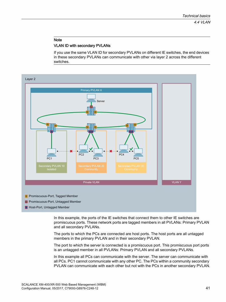
NoteVLAN ID with secondary PVLANs
If you use the same VLAN ID for secondary PVLANs on different IE switches, the end devices in these secondary PVLANs can communicate with other via layer 2 across the different switches.
VLAN YPrivate VLAN
Primary PVLAN X
Secondary PVLAN 10
Isolated
Secondary PVLAN 20
Community
Secondary PVLAN 30
Community
Server
PC1
PC2
PC3
PC4
PC5
In this example, the ports of the IE switches that connect them to other IE switches are promiscuous ports. These network ports are tagged members in all PVLANs: Primary PVLAN and all secondary PVLANs.
The ports to which the PCs are connected are host ports. The host ports are all untagged members in the primary PVLAN and in their secondary PVLAN.
The port to which the server is connected is a promiscuous port. This promiscuous port ports is an untagged member in all PVLANs: Primary PVLAN and all secondary PVLANs.
In this example all PCs can communicate with the server. The server can communicate with all PCs. PC1 cannot communicate with any other PC. The PCs within a community secondary PVLAN can communicate with each other but not with the PCs in another secondary PVLAN.
Technical basics4.4 VLAN
SCALANCE XM-400/XR-500 Web Based Management (WBM)Configuration Manual, 05/2017, C79000-G8976-C248-12 41

4.4.4 VLAN tunnelWith the Q-in-Q VLAN Tunnel function it is possible to forward the data traffic from different customer networks using a VLAN tunnel via a provider network. Every customer network has the full number of possible VLANs available.
A VLAN tunnel is established between provider switches that are configured at the boundaries of a provider network. A provider switch has the following types of ports:
● Access portThe provider switch is connected to a customer network via an access port.
– Incoming data trafficThe incoming data traffic at an access port is treated as if it were untagged ①. All incoming frames are expanded by a tag with the port VID of the access port ②. With frames that are already tagged, this means they are expanded by a second 802.1Q tag ③ the outer VLAN tag.
– Outgoing data trafficWith outgoing data traffic the outer tag is removed again at an access port.
● Core portThe provider switch is connected to a provider network via a core port.Core ports are members in the port VLAN of the access port or configured with the port type "Switch-Port VLAN Trunk".
Customer network A
VLAN ID
Customer network A
VLAN ID
Customer network B
Priority
Customer network B
Priority
Customer network C
untagged
Customer network C
untagged
Provider network
Technical basics4.4 VLAN
SCALANCE XM-400/XR-500 Web Based Management (WBM)42 Configuration Manual, 05/2017, C79000-G8976-C248-12

In this example the data traffic from the customer networks A, B and C is forwarded over the provider network using a VLAN tunnel. The frames from customer network A are tagged with a VLAN ID. The frames from customer network B are tagged with a priority. The frames from customer network C are untagged.
When the frames reach the relevant access port, they are expanded by a tag with the port VID of the access port and tunneled through the provider network. As soon as the frames leave the provider network, the outer VLAN tag (PVID) is removed again. The frames are forwarded in their original form. The priority of the frame is retained.
4.5 MirroringThe device provides the option of simultaneously channeling incoming or outgoing data streams via other interfaces for analysis or monitoring. This has no effect on the monitored data streams. This procedure is known as mirroring. In this menu section, you enable or disable mirroring and set the parameters.
Mirroring portsMirroring a port means that the data traffic at a port (mirrored port) of the IE switch is copied to another port (monitor port). You can mirror one or more ports to a monitor port.
If a protocol analyzer is connected to the monitor port, the data traffic at the mirrored port can be recorded without interrupting the connection. This means that the data traffic can be investigated without being affected. This is possible only if a free port is available on the device as the monitor port.
RSPANWith RSPAN (Remote Switched Port Analyzer) you can forward the data traffic of a mirroring session to the monitor port via a VLAN. On the RSPAN VLAN, the mirrored data traffic is not disturbed by other data.
Frames addressed directly to the monitoring source switch cannot be mirrored on the RSPAN destination port.
Technical basics4.5 Mirroring
SCALANCE XM-400/XR-500 Web Based Management (WBM)Configuration Manual, 05/2017, C79000-G8976-C248-12 43
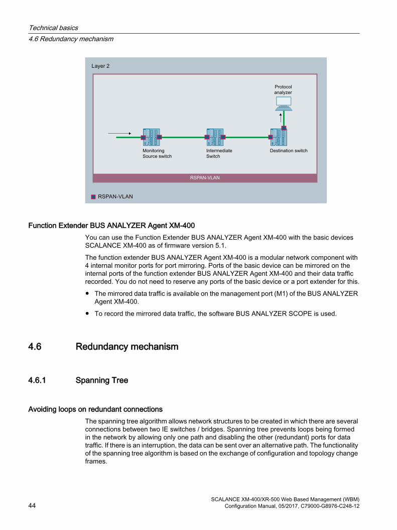
RSPAN-VLAN
Monitoring
Source switch
Destination switchIntermediate
Switch
Protocol
analyzer
Function Extender BUS ANALYZER Agent XM-400You can use the Function Extender BUS ANALYZER Agent XM-400 with the basic devices SCALANCE XM-400 as of firmware version 5.1.
The function extender BUS ANALYZER Agent XM-400 is a modular network component with 4 internal monitor ports for port mirroring. Ports of the basic device can be mirrored on the internal ports of the function extender BUS ANALYZER Agent XM-400 and their data traffic recorded. You do not need to reserve any ports of the basic device or a port extender for this.
● The mirrored data traffic is available on the management port (M1) of the BUS ANALYZER Agent XM-400.
● To record the mirrored data traffic, the software BUS ANALYZER SCOPE is used.
4.6 Redundancy mechanism
4.6.1 Spanning Tree
Avoiding loops on redundant connectionsThe spanning tree algorithm allows network structures to be created in which there are several connections between two IE switches / bridges. Spanning tree prevents loops being formed in the network by allowing only one path and disabling the other (redundant) ports for data traffic. If there is an interruption, the data can be sent over an alternative path. The functionality of the spanning tree algorithm is based on the exchange of configuration and topology change frames.
Technical basics4.6 Redundancy mechanism
SCALANCE XM-400/XR-500 Web Based Management (WBM)44 Configuration Manual, 05/2017, C79000-G8976-C248-12

Definition of the network topology using the configuration framesThe devices exchange configuration frames known as BPDUs (Bridge Protocol Data Units) with each other to calculate the topology. The root bridge is selected and the network topology created using these frames. BPDUs also bring about the status change of the root ports.
The root bridge is the bridge that controls the spanning tree algorithm for all involved components.
Once the root bridge has been specified, each device sets a root port. The root port is the port with the lowest path costs to the root bridge.
Response to changes in the network topologyIf nodes are added to a network or drop out of the network, this can affect the optimum path selection for data packets. To be able to respond to such changes, the root bridge sends configuration messages at regular intervals. The interval between two configuration messages can be set with the "Hello Time" parameter.
Keeping configuration information up to dateWith the "Max Age" parameter, you set the maximum age of configuration information. If a bridge has information that is older than the time set in "Max Age", it discards the message and initiates recalculation of the paths.
New configuration data is not used immediately by a bridge but only after the period specified in the "Forward Delay" parameter. This ensures that operation is only started with the new topology after all the bridges have the required information.
4.6.1.1 RSTP, MSTP, CIST
Rapid Spanning Tree Protocol (RSTP)One disadvantage of STP is that if there is a disruption or a device fails, the network needs to reconfigure itself: The devices start to negotiate new paths only when the interruption occurs. This can take up to 30 seconds. Fur this reason, STP was expanded to create the "Rapid Spanning Tree Protocol" (RSTP, IEEE 802.1w). This differs from STP essentially in that the devices are already collecting information about alternative routes during normal operation and do not need to gather this information after a disruption has occurred. This means that the reconfiguration time for an RSTP controlled network can be reduced to a few seconds.This is achieved by using the following functions:
● Edge ports (end node port)Edge ports are ports connected to an end device. A port that is defined as an edge port is activated immediately after connection establishment. If a spanning tree BPDU is received at an edge port, the port loses its role as edge port and it takes part in (R)STP again. If no further BPDU is received after a certain time has elapsed (3 x hello time), the port returns to the edge port status.
● Point-to-point (direct communication between two neighboring devices)
By directly linking the devices, a status change (reconfiguration of the ports) can be made without any delays.
Technical basics4.6 Redundancy mechanism
SCALANCE XM-400/XR-500 Web Based Management (WBM)Configuration Manual, 05/2017, C79000-G8976-C248-12 45

● Alternate port (substitute for the root port)
A substitute for the root port is configured. If the connection to the root bridge is lost, the device can establish a connection over the alternate port without any delay due to reconfiguration.
● Reaction to events
Rapid spanning tree reacts to events, for example an aborted connection, without delay. There is no waiting for timers as in spanning tree.
● Counter for the maximum bridge hopsThe number of bridge hops a package is allowed to make before it automatically becomes invalid.
In principle, therefore with rapid spanning tree, alternatives for many parameters are preconfigured and certain properties of the network structure taken into account to reduce the reconfiguration time.
Multiple Spanning Tree Protocol (MSTP)The Multiple Spanning Tree Protocol (MSTP) is a further development of the Rapid Spanning Tree Protocol. Among other things, it provides the option of operating several RSTP instances within different VLANs or VLAN groups and, for example, making paths available within the individual VLANs that the single Rapid Spanning Tree Protocol would globally block.
Common and Internal Spanning Tree (CIST)CIST identifies the internal instance used by the switch that is comparable in principle with an internal RSTP instance.
4.6.2 HRP
HRP - High Speed Redundancy ProtocolHRP is the name of a redundancy method for networks with a ring topology. The switches are interconnected via ring ports. One of the switches is configured as the redundancy manager (RM). The other switches are redundancy clients. Using test frames, the redundancy manager checks the ring to make sure it is not interrupted. The redundancy manager sends test frames via the ring ports and checks that they are received at the other ring port. The redundancy clients forward the test frames.
If the test frames of the RM no longer arrive at the other ring port due to an interruption, the RM switches through its two ring ports and informs the redundancy clients of the change immediately. The reconfiguration time after an interruption of the ring is a maximum of 300 ms.
Standby redundancy
Standby redundancy is a method with which rings each of which is protected by high-speed redundancy can be linked together redundantly. In the ring, a master/slave device pair is configured and these monitor each other via their ring ports. If a fault occurs, the data traffic
Technical basics4.6 Redundancy mechanism
SCALANCE XM-400/XR-500 Web Based Management (WBM)46 Configuration Manual, 05/2017, C79000-G8976-C248-12
is redirected from one Ethernet connection (standby port of the master or standby server) to another Ethernet connection (standby port of the slave).
Requirements
HRP● HRP is supported in ring topologies with up to 50 devices.
Exceeding this number of devices can lead to a loss of data traffic.
● For HRP, only devices that support this function can be used in the ring.
● Devices that do not support HRP must be linked to the ring using special devices with HRP capability. Up to the ring, this connection is not redundant.
● All devices must be interconnected via their ring ports. Multimode connections up to 3 km and single mode connections up to 26 km between two IE switches are possible. At greater distances, the specified reconfiguration time may be longer.
● A device in the ring must be configured as redundancy manager by selecting the "HRP manager" setting. On all other devices in the ring, either the "HRP Client" or "Automatic Redundancy Detection" mode must be activated.
● The standby ports must be disabled in spanning tree.
● You configure HRP in Web Based Management, Command Line Interface or using SNMP.
Standby redundancy● With standby coupling partners HRP must be set permanently.
● The ports of the standby coupling partners must be disabled in spanning tree.
● You configure standby redundancy in Web Based Management, Command Line Interface or using SNMP.
4.6.3 MRP
4.6.3.1 MRP - Media Redundancy Protocol The "MRP" method conforms to the Media Redundancy Protocol (MRP) specified in the following standard:
IEC 62439‑2 Release 1.0 (2010‑02) Industrial communication networks ‑ High availability automation networks Part 2: Media Redundancy Protocol (MRP)
The reconfiguration time after an interruption of the ring is a maximum of 200 ms.
Technical basics4.6 Redundancy mechanism
SCALANCE XM-400/XR-500 Web Based Management (WBM)Configuration Manual, 05/2017, C79000-G8976-C248-12 47

TopologyThe following figure shows a possible topology for devices in a ring with MRP.
S7-400 with
CP 443-1
Redundancy domain
S7-1500 with
CP 1543-1
SIMATIC S7-400
SIMATIC S7-400
SIMATIC S7-300
SCALANCE X208
SCALANCE
X310
SIMATIC
S7-400
PC
PC
Industrial Ethernet (Twisted Pair)
Operator Station
SCALANCE
XB205-3
SIMATIC
S7-1500
SIMATIC
S7-1500
SIMATIC
S7-1200SIMATIC
S7-1200
Figure 4-2 Example of a ring topology with the MRP media redundancy protocol
The following rules apply to a ring topology with media redundancy using MRP:
● All the devices connected within the ring topology are members of the same redundancy domain.
● One device in the ring is acting as redundancy manager.
● All other devices in the ring are redundancy clients.
Non MRP-compliant devices can be connected to the ring via a SCALANCE X switch or via a PC with a CP capable of MRP.
RequirementsRequirements for problem-free operation with the MRP media redundancy protocol are as follows:
● MRP is supported in ring topologies with up to 50 devices.Exceeding this number of devices can lead to a loss of data traffic.
● The ring in which you want to use MRP may only consist of devices that support this function.These include, for example, some of the Industrial Ethernet SCALANCE X switches, some of the communications processors (CPs) for SIMATIC S7 and PG/PC or non-Siemens devices that support this function.
Technical basics4.6 Redundancy mechanism
SCALANCE XM-400/XR-500 Web Based Management (WBM)48 Configuration Manual, 05/2017, C79000-G8976-C248-12

● All devices must be interconnected via their ring ports.Multimode connections up to 3 km and single mode connections up to 26 km between two SCALANCE X IE switches are possible. At greater distances, the specified reconfiguration time may be longer.
● "MRP" must be enabled for all devices in the ring.
● The connection settings (transmission medium / duplex) must be set to full duplex and at least 100 Mbps for all ring ports. Otherwise there may be a loss of data traffic.
– STEP 7: Set all the ports involved in the ring to "Automatic settings" in the "Options" tab of the properties dialog.
– WBM: If you configure with Web Based Management, the ring ports are set automatically to autonegotiation.
See alsoConfiguration in STEP 7 (Page 50)
Technical basics4.6 Redundancy mechanism
SCALANCE XM-400/XR-500 Web Based Management (WBM)Configuration Manual, 05/2017, C79000-G8976-C248-12 49

4.6.3.2 Configuration in WBM
RoleThe choice of role depends on the following use cases:
● You want to use MRP in a ring topology only with Siemens devices:
– For at least one device in the ring select "Automatic Redundancy Detection" or "MRP Auto Manager".
– For all other devices in the ring select "MRP Client" or "Automatic Redundancy Detection".
● You want to use MRP in a ring topology that also includes non-Siemens devices:
– For exactly one device in the ring select the role "MRP Auto Manager".
– For all other devices in the ring topology, select the role of "MRP client".
Note
The use of "Automatic Redundancy Detection" is not possible when using non-Siemens devices.
● You configure the devices in an MRP ring topology partly with WBM and partly with STEP 7:
– With the devices you configure using WBM, select "MRP Client" for all devices.
– With the devices that you configure using STEP 7, select precisely one device as "Manager" or "Manager (Auto)" and "MRP Client" for all other devices.
Note
If a device is assigned the role of "Manager" with STEP 7, all other devices in the ring must be assigned the "MRP Client" role. If there is a device with the "Manager" role and a device with the "Manager (Auto)"/"MRP Auto-Manager" in a ring, this can lead to circulating frames and therefore to failure of the network.
ConfigurationIn WBM, you configure MRP on the following pages:
● Configuration (Page 245)
● Ring (Page 284)
4.6.3.3 Configuration in STEP 7
Configuration in STEP 7To create the configuration in STEP 7, select the parameter group "Media redundancy" on the PROFINET interface.
Technical basics4.6 Redundancy mechanism
SCALANCE XM-400/XR-500 Web Based Management (WBM)50 Configuration Manual, 05/2017, C79000-G8976-C248-12

Set the following parameters for the MRP configuration of the device:
● Domain
● Role
● Ring port
● Diagnostic interrupts
These settings are described below.
NoteValid MRP configuration
In the MRP configuration in STEP 7, make sure that all devices in the ring have a valid MRP configuration before you close the ring. Otherwise, there may be circulating frames that will cause a failure in the network.
One device in the ring needs to be configured as "redundancy manager" and all other devices in the ring as "clients".
NoteNote factory settings
MRP is disabled and spanning tree enabled for the following brand new IE switches and those set to the factory settings:● SCALANCE XB-200 (Ethernet/IP variants)● SCALANCE XP-200 (Ethernet/IP variants)● SCALANCE XR-300WG ● SCALANCE XM-400● SCALANCE XR-500
To load a PROFINET configuration into one of the specified devices, first disable spanning tree on the device.
NoteReconfiguration only when the ring is open
First open the ring before you● change the MRP role or● reconfigure ring ports
NoteStarting up and restarting
The MRP settings are still effective after a restart of the device or a power failure and hot restart as long as the power failure does not occur within 90 seconds after the configuration change.
Technical basics4.6 Redundancy mechanism
SCALANCE XM-400/XR-500 Web Based Management (WBM)Configuration Manual, 05/2017, C79000-G8976-C248-12 51

NotePrioritized startup
If you configure MRP in a ring, you cannot use the "prioritized startup" function in PROFINET applications on the devices involved.
If you want to use the "prioritized startup" function, then disable MRP in the configuration.
In the STEP 7 configuration, set the role of the relevant device to "Not a node in the ring".
Domain
Single MRP ringsIf you want to configure a single MRP ring, leave the factory setting "mrpdomain 1" in the "Domain" drop-down list.
All devices configured in a ring with MRP must belong to the same redundancy domain. A device cannot belong to more than one redundancy domain in a single ring.
Multiple MRP ringsIf you configure multiple single MRP rings, the nodes of the ring will be assigned to the individual rings with the "Domain" parameter. Set the same domain for all devices within a ring. Set different domains for different rings. Devices that do not belong to the same ring must have different domains.
If you want to configure MRP multiple rings, as the central redundancy manager for up to four rings select a device that is capable of multiple rings. Specify different domains for all ring instances and assign these to the corresponding ring ports of the redundancy manager. Configure the other devices as clients. The same domain must be set for all devices within a ring.
Role
Note
Reconfiguration only when the ring is open!
The choice of role depends on the following use cases.
● You want to use MRP in a topology with one ring only with Siemens devices and without monitoring diagnostic interrupts:Assign all devices to the "mrpdomain‑1" domain and the role "Manager (Auto)".The device that actually takes over the role of redundancy manager, is negotiated by Siemens devices automatically.
● You want to use MRP in a topology with multiple rings only with Siemens devices and without monitoring diagnostic interrupts (MRP multiple rings):
– Assign all instances of the device that connects the rings the role of "Manager".
– For all other devices in the ring topology, select the role of "Client".
Technical basics4.6 Redundancy mechanism
SCALANCE XM-400/XR-500 Web Based Management (WBM)52 Configuration Manual, 05/2017, C79000-G8976-C248-12
● You want to use MRP in a ring topology that also includes non-Siemens devices or you want to receive diagnostic interrupts relating to the MRP status from a device (see "Diagnostic interrupts"):
– Assign precisely one device in the ring the role of "Manager (Auto)".
– For all other devices in the ring topology, select the role of "Client".
● You want to disable MRP:Select the option "Not node in the ring" if you do not want to operate the device within a ring topology with MRP.
NoteRole after resetting to factory settings
With brand new Siemens devices and those reset to the factory settings the following MRP role is set:● "Manager (Auto)"
CPs● "Automatic Redundancy Detection"
– SCALANCE X-200– SCALANCE XC-200– SCALANCE XB-200 (PROFINET variants)– SCALANCE XP-200 (PROFINET variants)– SCALANCE X-300– SCALANCE X-400
If you are operating a non-Siemens device as the redundancy manager in the ring, this may cause loss of the data traffic.
MRP is disabled and spanning tree enabled for the following brand new IE switches and those set to the factory settings:● SCALANCE XB-200 (Ethernet/IP variants)● SCALANCE XP-200 (Ethernet/IP variants)● SCALANCE XR-300WG● SCALANCE XM-400● SCALANCE XR-500
Ring port 1 / ring port 2Here, select the port you want to configure as ring port 1 and ring port 2.
With devices with more than 8 ports, not all ports can be selected as ring port.
Technical basics4.6 Redundancy mechanism
SCALANCE XM-400/XR-500 Web Based Management (WBM)Configuration Manual, 05/2017, C79000-G8976-C248-12 53

The drop-down list shows the selection of possible ports for each device type. If the ports are specified in the factory, the boxes are grayed out.
NOTICE
Ring ports after resetting to factory settings
If you reset to the factory settings, the ring port settings are also reset.
If other ports were used previously as ring ports before resetting, with the appropriate attachment, a previously correctly configured device can cause circulating frames and therefore the failure of the data traffic.
NoteReconfiguration only when the ring is open
First open the ring before you reconfigure the ring ports of a multiple ring manager.
Diagnostic interruptsEnable the "Diagnostic interrupts" option, if you want diagnostic interrupts relating to the MRP status on the local CPU to be output.
The following diagnostic interrupts can be generated:
● Wiring or port errorDiagnostic interrupts are generated if the following errors occur at the ring ports:
– Connection abort on a ring port
– A neighbor of the ring port does not support MRP.
– A ring port is connected to a non-ring port.
– A ring port is connected to the ring port of another MRP domain.
● Status change active/passive (redundancy manager only)If the status changes (active/passive) in a ring, a diagnostics interrupt is generated.
Parameter assignment of the redundancy is not set by STEP 7 (redundancy alternatives)This option only affects SCALANCE X switches. Select this option if you want to set the properties for media redundancy using alternative mechanisms such as WBM, CLI or SNMP.
If you enable this option, existing redundancy settings are retained and are not overwritten. The parameters in the "MRP configuration" box are then reset and grayed out. The entries then have no meaning.
Technical basics4.6 Redundancy mechanism
SCALANCE XM-400/XR-500 Web Based Management (WBM)54 Configuration Manual, 05/2017, C79000-G8976-C248-12

4.6.4 Standby
GeneralSCALANCE X switches support not only ring redundancy within a ring but also redundant linking of rings or open network segments (linear bus). In the redundant link, rings are connected together over Ethernet connections. This is achieved by configuring a master/slave device pair in one ring so that the devices monitor each other and, in the event of a fault, redirect the data traffic from the normally used master Ethernet connection to the substitute (slave) Ethernet connection.
Standby redundancy
SCALANCE XB205-3
as standby master
SCALANCE XB205-3
as standby slave
Operator Station Operator Stations
100 Mbit/s
100 Mbit/s
Industrial Ethernet / PROFINET (Twisted Pair)
S7-400
S7-1500 S7-1500
SCALANCE
XM408-8C
S7-300
IPC
SCALANCE
X204-2
SCALANCE X208
Industrial Ethernet / PROFINET (Fiber Optic)
SCALANCE
XR528-6M
SCALANCE
X308-2
SIMATIC
S7-1200
Figure 4-3 Example of a redundant link between rings
Technical basics4.6 Redundancy mechanism
SCALANCE XM-400/XR-500 Web Based Management (WBM)Configuration Manual, 05/2017, C79000-G8976-C248-12 55

For a redundant link as shown in the figure, two devices must be configured as standby redundancy switches within a network segment. In this case, network segments are rings with a redundancy manager. Instead of rings, network segments might also be linear.
The two standby redundancy switches connected in the configuration exchange data frames with each other to synchronize their operating statuses (one device is master and the other slave). If there are no problems, only the link from the master to the other network segment is active. If this link fails (for example due to a link-down or a device failure), the slave activates its link as long as the problem persists.
4.6.5 Link Check
Monitoring optical connections in the ringOn optical connections disturbances are possible in which the optical connection is not completely interrupted, but frames are lost sporadically. Such problems can, for example, be caused by defective optical cables, dirty connectors or device defects.
The redundancy manager of an HRP or MRP ring with optical connections detects a “non-recoverable ring error” with such a disturbance. The redundancy manager cannot eliminate the disturbance by closing the ring. Closing the ring in this case, would lead to circulating frames.
With the Link Check function, you can monitor the transmission quality of optical sections within an HRP or MRP ring, identify disturbed connections and under certain conditions turn them off. When the disturbed section is turned off, the redundancy manager can close the ring and restore communication.
How Link Check works
Behavior with an undisturbed connectionIf you enable Link Check on two connected ring ports, the two connection partners exchange Link Check frames cyclically on these ports. The frames received by one connection partner are sent back to the other.
When the devices receive back the frames they sent from the connection partner, the connection is prepared for Link Check. The connection partners then increase the send frequency of the Link Check test frames and the actual connection monitoring is active.
Behavior with a disturbanceWhen connection monitoring is enabled, you can see the number of sent and received Link Check test frames on the “Information > Redundancy >Link Check” page. Based on these statistics you can recognize smaller disturbances for which the disturbance does not yet cause the transmission line to be closed down by Link Check.
Link Check recognizes a connection as being disturbed and closes it down when too many test frames are lost within a given period. Link Check uses several intervals to be able to recognize sudden occurrences of errors as well as a continuous low error rate.
Technical basics4.6 Redundancy mechanism
SCALANCE XM-400/XR-500 Web Based Management (WBM)56 Configuration Manual, 05/2017, C79000-G8976-C248-12

A port that was turned off by Link Check must be reset to be able to communicate again. To do this you have 2 options:
● Pull out the connecting cable and plug it in again.
● Reset the function on both connection partners using the “Reset” button. This must be done on both devices within 30 s.
Note
When you use the “Reset” button, loops can form temporarily resulting in a loss of data traffic. The loop is automatically cleared again.
If this is not acceptable for your application, reset Link Check by pulling the cable and plugging it in again.
After resetting Link Check, the function is restarted on the port and the statistics are reset.
Configuring via a PROFINET IO controllerIf MRP is configured via a PROFINET IO controller, you can start the Link Check function for the optical ring ports of the 1st MRP ring instance using WBM or CLI.
When a new configuration is transferred, Link Check is automatically disabled on all ports that were not configured as ring ports of the 1st MRP ring instance.
Note
Events relating to the Link Check function are reported only indirectly by PROFINET IO. If the MRP diagnostics alarms are enabled and a ring port is disabled by LinkCheck, Profinet IO generates an error message that the connection no longer exists.
4.7 Link aggregation
Link aggregationWith link aggregation, several parallel physical connections with the same transmission speed are grouped together to form a logical connection with a higher transmission speed. This method based on IEEE 802.3ad is also known as port trunking or channel bundling.
Link aggregation works only with full duplex connections with the same transmission speed in point-to-point mode. This achieves multiplication of the bandwidth or transmission speed. If part of the connection fails, the data traffic is handled via the remaining parts of the connection.
To control and monitor, the Link Aggregation Control Layer (LACL) and the Link Aggregation Control Protocol (LACP) are used.
Technical basics4.7 Link aggregation
SCALANCE XM-400/XR-500 Web Based Management (WBM)Configuration Manual, 05/2017, C79000-G8976-C248-12 57
4.8 Routing function
IntroductionThe term routing describes the specification of routes for communication between different networks; in other words, how does a data packet from subnet A get to subnet B.
SCALANCE X supports the following routing functions:
● Static routingWith static routing, the routes are entered manually in the routing table.
● Router redundancyWith standardized VRRP (Virtual Router Redundancy Protocol), the availability of important gateways is increased by redundant routers.
– VRRPv2 (IPv4)
– VRRPv3 (IPv4 / IPv6)
● Dynamic routingThe entries in the routing table are dynamic and are updated continuously. The entries are created with one of the following dynamic routing protocols:
– OSPFv2 (IPv4)
– OSPFv3 (IPv6)
– RIPv2 (IPv4)
– RIPng (IPv6)
4.8.1 Static routingThe route is entered manually in the routing table. Enter the route in the routing table on the following pages.
● Layer 3 (IPv4) > Static Routes
● Layer 3 (IPv6) > Static Routes
See alsoStatic Routes (Page 351)
Technical basics4.8 Routing function
SCALANCE XM-400/XR-500 Web Based Management (WBM)58 Configuration Manual, 05/2017, C79000-G8976-C248-12

4.8.2 VRRP
4.8.2.1 VRRPv2
Router redundancy with VRRPWith the Virtual Router Redundancy Protocol (VRRP), the failure of a router in a network can be countered.
VRRP can only be used with virtual IP interfaces (VLAN interfaces) and not with router ports.
Several VRRP routers in a network segment are put together as a logical group representing a virtual router (VR). The group is defined using the virtual ID (VRID). Within the group, the VRID must be the same. The VRID can no longer be used for other groups.
The virtual router is assigned a virtual IP address and a virtual MAC address. One of the VRRP routers within the group is specified as the master router. The master router has priority 255. The other VRRP routers are backup routers. The master router assigns the virtual IP address and the virtual MAC address to its network interface. The master router sends VRRP packets (advertisements) to the backup routers at specific intervals. With the VRRP packets, the master router signals that it is still functioning. The master router also replies to the ARP queries.
If the virtual master router fails, a backup router takes over the role of the master router. The backup router with the highest priority becomes the master router. If the priority of the backup routers is the same, the higher MAC address decides. The backup router becomes the new virtual master router.
The new virtual master router adopts the virtual MAC and IP address. This means that no routing tables or ARP tables need to be updated. The consequences of a device failure are therefore minimized.
You configure VRRP in "Layer 3 (IPv4) > VRRP (Page 364)".
4.8.2.2 VRRP3Version 3 of VRRP is based on version 2.
Note● Enable routing to be able to use VRRPv3.● You can only use VRRPv3 in conjunction with VLAN interfaces. Router ports are not
supported.● Simultaneous operation of VRRP and VRRPv3 is not possible.● VRRPv3 supports IPv4 and IPv6. Both can be configured and operated at the same time
with VRRP3.
You configure VRRPv3 in:
IPv4: Layer 3 (IPv4 )> VRRPv3 (Page 372)
IPv6: Layer 3 (IPv6 )> VRRPv3 (Page 422)
Technical basics4.8 Routing function
SCALANCE XM-400/XR-500 Web Based Management (WBM)Configuration Manual, 05/2017, C79000-G8976-C248-12 59

4.8.3 OSPF
4.8.3.1 OSPFv2
Dynamic routing with OSPFv2OSPF (Open Shortest Path First) is a cost-based routing protocol. To calculate the shortest and most cost-effective route, the Short Path First algorithm by Dijkstra is used. OSPF was developed by the IETF (Internet Engineering Task Force).
You configure OSPFv2 in "Layer 3 (IPv4) > OSPFv2 (Page 380)".
OSPFv2 divides an autonomous system (AS) into different areas.
Areas in OSPF The following areas exist:
● BackboneThe backbone area is area 0.0.0.0. All other areas are connected to this area. The backbone area is connected either directly or via virtual connections with other areas.All routing information is available in the backbone area. As a result, the backbone area is responsible for forwarding information between different areas.
● Stub AreaThis area contains the routes within its area within the autonomous system and the standard route out of the autonomous system. The destinations outside this autonomous system are assigned to the standard route.
● Totally Stubby AreaThis area knows only the routes within its area and the standard route out of the area.
● Not So Stubby Area (NSSA)This area can forward (redistribute) packets from other autonomous systems into the areas of its own autonomous system. The packets are further distributed by the NSSA router.
Routers of OSPFOSPF distinguishes the following router types:
● Internal router (IR)All OSPF interfaces of the router are assigned to the same area.
● Area Border Router (ABR)The OSPF interfaces of the router are assigned to different areas. One OSPF interface is assigned to the backbone area. Where possible, routes are grouped together.
● Backbone Router (BR)At least one of the OSPF interfaces is assigned to the backbone area.
● Autonomous System Border Router (ASBR)One interface of the router is connected to a different AS, for example an AS that uses the routing protocol RIP.
Technical basics4.8 Routing function
SCALANCE XM-400/XR-500 Web Based Management (WBM)60 Configuration Manual, 05/2017, C79000-G8976-C248-12
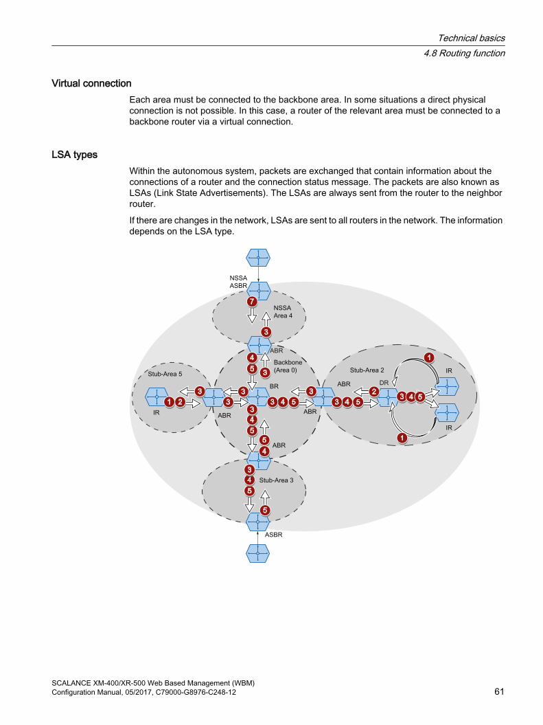
Virtual connectionEach area must be connected to the backbone area. In some situations a direct physical connection is not possible. In this case, a router of the relevant area must be connected to a backbone router via a virtual connection.
LSA typesWithin the autonomous system, packets are exchanged that contain information about the connections of a router and the connection status message. The packets are also known as LSAs (Link State Advertisements). The LSAs are always sent from the router to the neighbor router.
If there are changes in the network, LSAs are sent to all routers in the network. The information depends on the LSA type.
Technical basics4.8 Routing function
SCALANCE XM-400/XR-500 Web Based Management (WBM)Configuration Manual, 05/2017, C79000-G8976-C248-12 61

Router LSA (LSA Type 1)The LSA Type 1 is only sent within an area. For each active connection of the router that belongs to the area in consideration, an LSA Type 1 is generated. The LSA Type 1 contains information about the status and the costs of the connection, for example IP address, network mask, network typeNetwork LSA (LSA Type 2)The LSA Type 2 is sent only within an area. For each network that belongs to the relevant area, the router generates an LSA Type 2. If several routers are interconnected in a network, the LSA Type 2 is sent by the designated router (DR). The LSA Type 2 includes the network address, the network mask and a list of routers that are connected to the networkSummary LSA (LSA Type 3 / LSA Type 4) The Summary LSA is generated by the area border router and sent into the area. The Summary LSA contains information about routes outside the area but inside the AS. Where possible, the routes are grouped together. ● Summary LSA (LSA Type 3)
The LSA Type 3 describes the routes to the networks and advertises the standard route to the areas.
● AS Summary LSA (LSA Type 4)The LSA Type 4 describes the routes to the ASBR.
External LSA (LSA Type 5 / LSA Type 7)The External LSA is generated by the ASBR. The LSA type depends on the area.● AS External LSA (LSA Type 5)
The LSA Type 5 is sent by the AS border router into the areas of the autonomous system except the Stub and NSSA areas. The LSA contains information about routes to a network in another AS. The routes are either created manually or learned externally. The ASBR uses LSA Type 5 to distribute standard routes to the backbone area.
● NSSA External LSA (LSA Type 7)The LSA Type 7 is generated by the AS border router of an NSSA. The router is also known as the NSSA ASBR. The LSA Type 7 is sent only within the NSSA. If the P bit in LSA Type 7 = 1, these LSAs are converted to LSA Type 5 by the ABR and sent to the backbone area.
Technical basics4.8 Routing function
SCALANCE XM-400/XR-500 Web Based Management (WBM)62 Configuration Manual, 05/2017, C79000-G8976-C248-12

Establishing the neighborhoodThe router runs through the following statuses to establish a connection to the neighbor router.
1. Attempt state / Init stateThe router activates OSPF and begins to send and receive Hello packets. Based on the received Hello packets, the router learns which OSPF routers are in its vicinity. The router checks the content of the Hello packet. The Hello packet also contains the list of the neighbor routers (neighbor table) of the "sender".
2. Two way stateIf, for example, the ID of the area, the area type and the settings for the times match, a connection (adjacency) can be established to the neighbor. In a point-to-point network, the connection is established directly. If several neighbor routers can be reached in a network, the designated router (DR) and the designated backup router (DBR) are identified based on Hello packets. The router with the highest router priority becomes the designated router. If two routers have the same router priority, the router with the highest router ID becomes the designated router. The router establishes a connection to the designated router.
3. Exchangestart stateThe neighbor routers decide which router starts communication. The router with the higher router ID becomes the designated router.
4. Exchange stateThe neighbor routers send packets that describe the content of their neighborhood database. The neighborhood database (link state database - LSDB) contains information on the topology of the network.
5. Loading stateThe router completes the received information. If the router still has questions relating to the status of a specific connection, it sends a link state request. The neighbor router sends a response (link state update). The response contains a suitable LSA. The router confirms receipt of the response (link state acknowledge).
6. Full StateThe information exchange with the neighbor router is completed. The neighborhood database of the neighbor router is the same. Based on the Short Path First algorithm, the router calculates a route to every destination. The route is entered in the routing table.
Check the neighborhoodThe Hello packets are only used to establish the neighborhood relations. Hello packets are used to check the connection to the neighbor router by sending them cyclically. If no Hello packet is received within a certain interval (dead interval), the connection to the neighbor is marked as "down". The relevant entries are deleted.
Updating the neighborhood databaseOnce the neighborhood database is established, LSAs are sent to all routers in the network if there are changes in the topology.
Technical basics4.8 Routing function
SCALANCE XM-400/XR-500 Web Based Management (WBM)Configuration Manual, 05/2017, C79000-G8976-C248-12 63

4.8.3.2 OSPFv3
Version 3 of OSPF is based on version 2 and is only used with IPv6. A large part of the routing mechanisms was adopted. OSPFv3 is defined in the RFCs 2740 and 5340.
You configure OSPFv3 under "Layer 3 (IPv6) > OSPFv3".
The following has not changed:
● The statuses that a router runs through to establish a connection to the neighbor router.
● The areas : Backbone, Stub Area, Totally Stubby Area, Not So Stubby Area (NSSA)
● The router types: Internal Router (IR), Area Border Router (ABR), Backbone Router (BR), Autonomous System Area Border Router (ASBR), Designated Router (DR)
● The router ID, the area ID and the ID of the LSA are entered in the IPv4 address format: x.x.x.x
What has changed?
TermsThe terms network or subnet are replaced by link.
AuthenticationThe authentication was removed. Instead OSPFv3 uses IPsec, that is implemented in IPv6.
Neighbor routersThe neighbor routers are identified via the router ID.
Neighbor database
The neighbor database (link state database - LSDB) is divided into different areas of application:
● Link scope LSDBContains the link LSA
● Area scope LSDBcontains the following LSAs
– Router LSA
– Network LSA
– Inter-area prefix LSA
– Inter area router LSA
– Intra area prefix LSA
● AS scope LSDBContains the AS external LSA
Technical basics4.8 Routing function
SCALANCE XM-400/XR-500 Web Based Management (WBM)64 Configuration Manual, 05/2017, C79000-G8976-C248-12

LSA typesTwo new LSA types were defined for OSPFv3.
OSPFv2 OSPFv3 Who Within Description1 Router LSA 0x2001 Router
LSAevery router
Area No longer contains address information. This is contained in the new LSA type 2009.
2 Network LSA 0x2002 Network LSA
DR Area No longer contains address information. This is contained in the new LSA type 2009.
3 Summary LSA
0x2003 Inter-area prefix LSA
ABR Area Same function as in OSPFv2, simply renamed
4 AS Summary LSA
0x2004 Inter-Area Router LSA
ABR Area Same function as in OSPFv2, simply renamed
5 AS External LSA
0x4005 AS Exter‐nal LSA
ASBR AS Same function as in OSPFv2, simply renamed
7 NSSA Exter‐nal LSA
0x2007 Type 7 LSA
NSSA ASBR
NSSA Same function as in OSPFv2, simply renamed
0x2008 Link LSA every router
Link The LSA is sent by the router to every router linked to it. The LSA contains the link local address of the router and a list with IPv6 prefixes configured on the link.
0x2009 Intra area prefix LSA
every router
Area The LSA is sent only within an area. The LSA contains the IPv6 prefixes connected to the router or network.
In contrast to OSPFv2, OSPFv3 can forward unknown LSA types. Previously these were deleted and not distributed further.
4.8.4 RIP
4.8.4.1 RIPv2
Dynamic routing with RIPv2The Routing Information Protocol (RIPv2) is used to create routing tables automatically. RIPv2 is used in autonomous systems (AS) with a maximum of 15 routers. It is based on the Distance-Vector algorithm.
RIPv2 was developed by the IETF (Internet Engineering Task Force) and is described in RFC 2453.
You configure RIPv2 in "Layer 3 (IPv4) > RIPv2".
Setting up a routing tableSince a router initially only knows its directly connected networks, it sends a request to its direct neighbor routers. As the reply, it receives the routing tables of the neighbor routers. Based on the information it receives, the router set up its own routing table.
The routing table contains entries for all possible destinations. Each entry includes the distance to the destination and the first router on the route.
Technical basics4.8 Routing function
SCALANCE XM-400/XR-500 Web Based Management (WBM)Configuration Manual, 05/2017, C79000-G8976-C248-12 65

The distance is also known as the metric. This indicates the number of routers to be passed through on the route to the destination (hop count). The maximum distance is 15 routers (hops).
Updating the routing tableOnce the routing table is set up, the router sends its routing table to each direct neighbor router via the UDP port 520 at intervals of 30 seconds.
The router compares new routing information with its existing routing table. If the new information includes shorter routes, the existing routes are overwritten. The router only keeps the shortest route to a destination.
Checking neighbor routersIf a router does not receive messages from a neighbor router for longer than 180 seconds, it marks the router as being invalid. The router assigns the metric 16 for the neighbor router.
4.8.4.2 RIPngRIPng (RIP next generation) is only used with IPv6 and is defined in RFC 2080. As with RIP (IPv4), RIPng is based on the distance vector algorithm of Bellman-Ford.
In contrast to RIPv2, RIPng is activated directly on the layer 3 interface (VLAN interface / router port) and not globally on the device.
RIPng uses the UDP port 521 and RIP the UDP port 520.
You configure RIPng in "Layer 3 (IPv6) > RIPng".
4.8.5 PIMProtocol Independent Multicast (PIM) allows the routing of multicast packets, regardless of the routing protocol such as OSPFv2 or static routing (IPv4). PIM expands the routing information of the unicast routing protocol active on the router with additional information for multicast operation.
Requirements for PIM:
● IGMP is enabled on the first hop and last hop of the routing topology.
● PIM is enabled on all routers of the routing topology.
● There is at least one rendezvous point (RP).
● In every subnet there is a designated router (DR).
● The DR must also be the IGMP querier.
PIM networkPIM operates in the sparse mode designed for networks with a low node density.
Technical basics4.8 Routing function
SCALANCE XM-400/XR-500 Web Based Management (WBM)66 Configuration Manual, 05/2017, C79000-G8976-C248-12
Sparse mode (SM)If a router receives a multicast, it sends this information to the rendezvous point (RP). A device that wants to receive a multicast sends an IGMP Join to the routers in its subnet. The designated router (DR) of the network sends this request to the RP. The RP therefore has the unicast address of the sender and a unicast address for the recipient, that of the DR.
In Sparse mode between the sender and recipient the shortest path is selected based on the routing table and the information can be sent.
Bidirectional multicast and designated forwarderThe "Bidirectional multicast" functionality is a variant of the Sparse mode in which the information between sender and recipient is always sent via the rendezvous point.
In Bidirectional multicast the DR is replaced by the designated forwarder (DF). When the DF receives an IGMP Join, it sends a (*, G) message to the RP. The RP replaces the * with the source and so establishes the connection. Only the DF forwards the multicast.
Rendezvous point (RP) and bootstrap router (BSR)The rendezvous point manages the information about the sender and recipient: You can create RPs statically or define RP candidates.
When you define RP candidates you require a bootstrap router. The BSR coordinates the RP candidates and decides on an RP. You define BSR candidates of which one becomes the bootstrap router.
BSR borderWith the "BSR border" function you can divide a PIM network into domains. There is no BSR communication between the PIM domains so a BSR is selected in every domain. The BSR of the domain selects an RP for the domain.
MSDPThe RPs communicate beyond PIM domain boundaries using MSDP and synchronize the multicast groups they receive. This means that a device in domain A can receive a multicast although the information about the sender is managed by the RP in domain B.
Source specific multicast (SSM)PIM source specific multicast is a further variant of Sparse mode that manages without rendezvous points. Via IGMPv3, the recipient directly informs the router of the source and the multicast it would like to receive.
Technical basics4.8 Routing function
SCALANCE XM-400/XR-500 Web Based Management (WBM)Configuration Manual, 05/2017, C79000-G8976-C248-12 67

Example
VLAN 1 VLAN 3
VLAN 4
VLAN 2
Unicast routing topology
Source
Recipient
Rendezvous point
IGMP querier and DR
In this example the source sends a multicast to the connected router. The router sends this information to the rendezvous point.
The recipient sends an IGPM Join to its IGMP querier and designated router. The DR forwards the request to the RP.
Based on the routing table, the shortest path is selected for the multicast.
4.9 NAT/NAPT
Note
NAT/NAPT is possible only on layer 3 of the ISO/OSI reference model. To use the NAT function, the networks must use the IP protocol.
When using the ISO protocol that operates at layer 2, it is not possible to use NAT.
In Network Address Translation (NAT) IP subnets are divided into "Inside" and "Outside". The division is from the perspective of a NAT interface. All networks reachable via the NAT interface
Technical basics4.9 NAT/NAPT
SCALANCE XM-400/XR-500 Web Based Management (WBM)68 Configuration Manual, 05/2017, C79000-G8976-C248-12

itself count as "Outside" for this interface. All networks reachable via other IP interfaces of the same device count as "Inside" for the NAT interface.
If there s routing via the NAT interface, the source or destination IP addresses of the transferred data packets are changed at the transition between "Inside" and "Outside". Whether or not the source or destination IP address is changed depends on the communications direction. It is always the IP address of the communications node that is located "Inside" that is adapted. Depending on the perspective the IP address of a communications node is always designated as "Local" or "Global".
PerspectiveLocal Global
Position Inside An actual IP address that is as‐signed to a device in the internal network. This address cannot be reached from the external network.
An IP address at which an internal device can be reached from the external network.
Outside An actual IP address that is assigned to a device in the external network.Since only "Inside" addresses are converted, there is no distinction made between outside local and outside global.
ExampleIn the example two IP subnets are connected together via an IE switch. The division is from the perspective of the NAT interface 10.0.0.155. The communication of PC2 with PC1 is implemented via NAT/NAPT.
VLAN Y: 10.0.0.0/24VLAN X: 192.168.16.0/24
The actual IP address of PC1 (inside local) is implemented statically with NAT. For PC2, PC1 can be reached at the inside global address.
PerspectiveLocal Global
Position Inside 192.168.16.150 10.0.0.7Outside 10.0.0.10
Technical basics4.9 NAT/NAPT
SCALANCE XM-400/XR-500 Web Based Management (WBM)Configuration Manual, 05/2017, C79000-G8976-C248-12 69

The actual IP address of PC1 (inside local) is implemented with NAPT (Network Address and Port Translation).. For PC2, PC1 can be reached at the inside global address.
PerspectiveLocal Global
Position Inside 192.168.16.150:80 10.0.0.7:80Outside 10.0.0.10:1660
Computing capacityDue to the load limitation of the CPU packet receipt of the device is limited to 300 packets a second. This corresponds to a maximum data through of 1.7 Mbps. This load limitation does not apply per interface but generally for all packets going the CPU.
The entire NAT communication runs via the CPU and therefore represents competition for IP communication going to the CPU, e.g. WBM and Telnet.
Note that a large part of the computing capacity is occupied if you use NAT. This can slow down access via Telnet or WBM.
NATWith Network Address Translation (NAT), the IP address in a data packet is replaced by another. NAT is normally used on a gateway between an internal network and an external network.
With source NAT, the inside local source address of an IP packet from a device in the internal network is rewritten by a NAT device to an inside global address at the gateway.
With destination NAT, the inside global source address of an IP packet from a device in the external network is rewritten by a NAT device to an inside local address at the gateway.
To translate the internal into the external IP address and back, the NAT device maintains a translation list. The address assignment can be dynamic or static. You configure NAT in "Layer 3 (IPv4) > NAT (Page 345)".
NAPTIn "Network Address Port Translation" (NAPT), several internal source IP addresses are translated into the same external IP address. To identify the individual nodes, the port of the internal device is also stored in the translation list of the NAT device and translated for the external address.
If several internal devices send a query to the same external destination IP address via the NAT device, the NAT device enters its own external source IP address in the header of these forwarded frames. Since the forwarded frames have the same external source IP address, the NAT device assigns the frames to the devices using a different port number.
If a device from the external network wants to use a service in the internal network, the translation list for the static address assignment needs to be configured. You configure NAPT in "Layer 3 (IPv4) > NAT > NAPT (Page 349)".
Technical basics4.9 NAT/NAPT
SCALANCE XM-400/XR-500 Web Based Management (WBM)70 Configuration Manual, 05/2017, C79000-G8976-C248-12

NAT/NAPT and IP routingYou can enable NAT/NAPT and IP routing at the same time. In this case, you need to regulate the reachability of internal addresses from external networks with ACL rules.
Technical basics4.9 NAT/NAPT
SCALANCE XM-400/XR-500 Web Based Management (WBM)Configuration Manual, 05/2017, C79000-G8976-C248-12 71

Technical basics4.9 NAT/NAPT
SCALANCE XM-400/XR-500 Web Based Management (WBM)72 Configuration Manual, 05/2017, C79000-G8976-C248-12

Configuring with Web Based Management 55.1 Web Based Management
How it works The device has an integrated HTTP server for Web Based Management (WBM). If a device is addressed using an Internet browser, it returns HTML pages to the client PC depending on the user input.
The user enters the configuration data in the HTML pages sent by the device. The device evaluates this information and generates reply pages dynamically.
The advantage of this method is that only an Internet browser is required on the client.
NoteSecure connection
WBM also allows you to establish a secure connection via HTTPS.
Use HTTPS for protected transfer of your data. If you wish to access WBM only via a secure connection, activate the option "HTTPS Server only" under "System > Configuration".
RequirementsWBM display
● The device has an IP address.
● There is a connection between the device and the client PC. With the ping command, you can check whether or not a device can be reached.
● Access using HTTPS is enabled.
● JavaScript is activated in the Internet browser.
● The Internet browser must not be set so that it reloads the page from the server each time the page is accessed. The updating of the dynamic content of the page is ensured by other mechanisms. In the Internet Explorer, you can make the appropriate setting in the "Options > Internet Options > General" menu in the section "Browsing history" with the "Settings" button. Under "Check for newer versions of stored pages:", select "Automatically".
● If a firewall is used, the relevant ports must be opened.
– For access using HTTP: TCP port 80
– For access using HTTPS: TCP port 443
SCALANCE XM-400/XR-500 Web Based Management (WBM)Configuration Manual, 05/2017, C79000-G8976-C248-12 73

The display of the WBM was tested with the following desktop Internet browsers:
● Microsoft Internet Explorer 11
● Mozilla Firefox 45 ESR
● Google Chrome V57
NoteCompatibility view
In Microsoft Internet Explorer, disable the compatibility view to ensure correct display and to allow problem-free configuration using WBM.
Display of the WBM on mobile devices
For mobile devices, the following minimum requirements must be met:
Resolution Operating system960 x 640 pixels Android as of version 4.2.1
iOS as of version 6.0.2
Tested with the following Internet browsers for mobile devices:
● Apple Safari as of version 8 on iOS as of V8.1.3 (iPad Mini Model A1432)
● Google Chrome as of version 40 on Android as of version 5.0.2 (Nexus 7C Asus)
● Mozilla Firefox as of version 35 on Android as of version 5.0.2 (Nexus 7C Asus)
NoteDisplay of the WBM and working with it on mobile devices
The display on the WBM pages and how you work with them on mobile devices may differ compared with the same pages on desktop devices. Some pages also have an optimized display for mobile devices.
5.2 Login
Establishing a connection to a deviceFollow the steps below to establish a connection to a device using an Internet browser:
1. There is a connection between the device and the client PC. With the ping command, you can check whether or not a connection exists.
2. In the address box of the Internet browser, enter the IP address or the URL of the device. If there is a problem-free connection to the device, the logon page of Web Based Management (WBM)is displayed.
Configuring with Web Based Management5.2 Login
SCALANCE XM-400/XR-500 Web Based Management (WBM)74 Configuration Manual, 05/2017, C79000-G8976-C248-12

Logging on using the Internet browserSelecting the language of the WBM
1. From the drop-down list at the top right, select the language version of the WBM pages.
2. Click the "Go" button to change to the selected language.
NoteAvailable languages
As of version 5.0 English and German are available. Other languages will follow in a later version.
Logon with HTTPThere are two ways in which you can log on via HTTP. You either use the logon option in the center of the browser window or the logon option in the upper left area of the browser window.
Configuring with Web Based Management5.2 Login
SCALANCE XM-400/XR-500 Web Based Management (WBM)Configuration Manual, 05/2017, C79000-G8976-C248-12 75

The following steps apply when logging on, whichever of the above options you choose:
1. "Name" input box:
– When you log in for the first time or following a "Restore Factory Defaults and Restart", enter the user preset in the factory "admin".With this user account, you can change the settings of the device (read and write access to the configuration data).
Note
Default user "user" set in the factory
As of firmware version 6.0 the default user set in the factory "user" is no longer available when the product ships.
If you update a device to the firmware V6.0 the default user set in the factory "user" is initially still available. If you reset the device to the factory settings ("Restore Factory Defaults and Restart") the default user set in the factory "user" is deleted.
You can create users with the role "user".
– Enter the user name of the created user account. You configure local user accounts and roles in "Security > Users".
2. "Password" input box:
– When you log in for the first time or following a "Restore Factory Defaults and Restart", enter the password of the default user preset in the factory "admin": "admin".
– Enter the password of the relevant user account.
3. Click the "Login" button or confirm your input with "Enter".When you log in for the first time or following a "Restore Factory Defaults and Restart", with the preset user "admin" you will be prompted to change the password.The new password must meet the following password policies:
– Password length: at least 8 characters, maximum 128 characters.
– at least 1 uppercase letter
– at least 1 special character
– at least 1 number
You need to repeat the password as confirmation. The password entries must match.Click the "Set Values" button to complete the action and activate the new password.
Once you have logged in successfully, the start page appears.
Logon with HTTPSWeb Based Management also allows you to connect to the device over the secure connection of the HTTPS protocol. Follow these steps:
1. Click on the link "Switch to secure HTTP" on the login page or enter "https://" and the IP address of the device in the address box of the Internet browser.
2. Check the displayed certificate warning and confirm it if applicable.The logon page of Web Based Management appears.
Configuring with Web Based Management5.2 Login
SCALANCE XM-400/XR-500 Web Based Management (WBM)76 Configuration Manual, 05/2017, C79000-G8976-C248-12

3. "Name" input box:
– When you log in for the first time or following a "Restore Factory Defaults and Restart", enter the user preset in the factory "admin".With this user account, you can change the settings of the device (read and write access to the configuration data).
Note
Default user "user" set in the factory
As of firmware version 6.0 the default user set in the factory "user" is no longer available when the product ships.
If you update a device to the firmware V6.0 the default user set in the factory "user" is initially still available. If you reset the device to the factory settings ("Restore Factory Defaults and Restart") the default user set in the factory "user" is deleted.
You can create users with the role "user".
– Enter the user name of the created user account. You configure local user accounts and roles in "Security > Users".
4. "Password" input box:
– When you log in for the first time or following a "Restore Factory Defaults and Restart", enter the password of the default user preset in the factory "admin": "admin".
– Enter the password of the relevant user account.
5. Click the "Login" button or confirm your input with "Enter".When you log in for the first time or following a "Restore Factory Defaults and Restart", with the preset user "admin" you will be prompted to change the password.The new password must meet the following password policies:
– Password length: at least 8 characters, maximum 128 characters.
– at least 1 uppercase letter
– at least 1 special character
– at least 1 number
You need to repeat the password as confirmation. The password entries must match.Click the "Set Values" button to complete the action and activate the new password.
Once you have logged in successfully, the start page appears.
Configuring with Web Based Management5.2 Login
SCALANCE XM-400/XR-500 Web Based Management (WBM)Configuration Manual, 05/2017, C79000-G8976-C248-12 77

5.3 The "Information" menu
5.3.1 Start page
View of the Start page When you enter the IP address of the device, the start page is displayed after a successful login. You cannot configure anything on this page.
General layout of the WBM pagesThe following areas are generally available on every WBM page:
● Selection area (1): Top area
● Display area (2): Top area
● Navigation area (3): Left-hand area
● Content area (4): Middle area
Configuring with Web Based Management5.3 The "Information" menu
SCALANCE XM-400/XR-500 Web Based Management (WBM)78 Configuration Manual, 05/2017, C79000-G8976-C248-12

Selection area (1)The following is available in the selection area:
● Logo of Siemens AGWhen you click on the logo, you arrive at the Internet page of the corresponding basic device in Siemens Industry Online Support.
● Display of: "System Location / System Name"
– System location" contains the location of the device.With the settings when the device ships, the in-band port IP address of the device is displayed.
– "System Name" is the device name. With the settings when the device ships, the device type is displayed.
You can change the content of this display with "System > General > Devices".
● Drop-down list for language selection
● System date and system time with status displayYou can change the content of this display with "System > System Time.If the system time is not set, the status is . If the system time is configured, but the system time cannot be synchronized, a yellow warning triangle can be seen. Check whether the time server can be reached. If necessary adapt your configuration. If the system time is set and/or can be synchronized, the status is .
Display area (2)In the upper part of the display area, you can see the full title of the currently selected menu item.
In the lower part of the display area, you will find the following:
● LogoutYou can log out from any WBM page by clicking the "Logout" link.
● LED simulation Each component of a device has one or more LEDs that provide information on the operating state of the device. Depending on its location, direct access to the device may not always be possible. Web Based Management therefore displays simulated LEDs. Unoccupied slots or unused connectors are displayed as gray LEDs. The meaning of the LED displays is described in the operating instructions.If you click the simulated "SELECT/SET" button, you can change the display mode (LEDs DM or D1/D2).If you click this button, you open the window for the LED simulation. You can show this window during a change of menu and move it as necessary. To close the LED simulation, click the "Close" button in the LED simulation window.
● Help When you click this button, the help page of the currently selected menu item is opened in a new browser window.The help page contains a description of the content area. Under certain circumstances, options are described that are not available on the device.
Configuring with Web Based Management5.3 The "Information" menu
SCALANCE XM-400/XR-500 Web Based Management (WBM)Configuration Manual, 05/2017, C79000-G8976-C248-12 79

● Print Print If you click this button, a popup window opens. The popup window contains a view of the page content optimized for printers.
NotePrinting larger tables
If you want to print large tables, please use the "Print preview" function of your Internet browser.
● FavoritesWhen the product ships, the button is disabled on all pages .If you click this button, the symbol changes and the currently open page or currently open tap is marked as favorite. Once you have enabled the button once, the navigation area is divided into two tabs. The first tab "Menu" contains all the available menus as previously. The second tab "Favorites" contains all the pages/tabs that you selected as favourites. On the "Favorites" tab the pages/tabs are arranged according to the structure in the "Menu" tab.If you disable all the favorites you have created, the "Favorites" is removed again.
Navigation area (3)In the navigation area, you have various menus available. Click the individual menus to display the submenus. The submenus contain pages on which information is available or with which you can create configurations. These pages are always displayed in the content area.
If you have created favorites, the navigation area is divided into two tabs: "Menu" and "Favorites".
Configuring with Web Based Management5.3 The "Information" menu
SCALANCE XM-400/XR-500 Web Based Management (WBM)80 Configuration Manual, 05/2017, C79000-G8976-C248-12

Content area (4)The content area shows a graphic of the device. The graphic is dynamic. The basic device is always shown. If extenders/media modules are connected to the basic device, these are also shown.
Figure 5-1 Example of a device graphic: SCALANCE XM416-4C with one port extender PE408
The following is displayed below the device graphic:
● PROFINET Name of Station Shows the PROFINET device name.
● System Name Shows the name of the device.
● Device Type Shows the type designation of the device.
● PROFINET AR Status Shows the PROFINET IO application relation status.
– Online There is a connection to a PROFINET controller. The PROFINET controller has downloaded its configuration data to the device. The device can send status data to the PROFINET controller. In this status, the parameters set via the PROFINET controller cannot be configured on the device.
– Offline There is no connection to a PROFINET controller.
● Power Supply 1 / Power Supply 2
– Up Power supply 1 or 2 is applied.
– Down Power supply 1 or 2 is not applied or is below the permitted voltage.
Configuring with Web Based Management5.3 The "Information" menu
SCALANCE XM-400/XR-500 Web Based Management (WBM)Configuration Manual, 05/2017, C79000-G8976-C248-12 81

● PLUG ConfigurationShows the status of the configuration data on the PLUG, refer to the section "System > PLUG > PLUG Configuration".
● PLUG LicenseShows the status of the license on the PLUG, refer to the section "System >PLUG > PLUG License".
● Fault Status Shows the fault status of the device.
Buttons you require oftenThe pages of the WBM contain the following standard buttons:
● Refresh the display with "Refresh"Web Based Management pages that display current parameters have a "Refresh" button at the lower edge of the page. Click this button to request up-to-date information from the device for the current page.
Note
If you click the "Refresh" button, before you have transferred your configuration changes to the device using the "Set Values" button, your changes will be deleted and the previous configuration will be loaded from the device and displayed here.
● Save entries with "Set Values"Pages in which you can make configuration settings have a "Set Values" button at the lower edge. The button only becomes active if you change at least one value on the page. Click this button to save the configuration data you have entered on the device. Once you have saved, the button becomes inactive again.
Note
Changing configuration data is possible only with the "admin" role.
● Create entries with "Create"Pages in which you can make new entries have a "Create" button at the lower edge. Click this button to create a new entry.
● Delete entries with "Delete"Pages in which you can delete entries have a "Delete" button at the lower edge. Click this button to delete the previously selected entries from the device memory. Deleting also results in an update of the page in the WBM.
● Page down with "Next"On pages with a lot of data records the number of data records that can be displayed on a page is limited. Click the "Next" button to page down through the data records.
● Page back with "Prev"On pages with a lot of data records the number of data records that can be displayed on a page is limited. Click the "Prev" button to page back through the data records.
Configuring with Web Based Management5.3 The "Information" menu
SCALANCE XM-400/XR-500 Web Based Management (WBM)82 Configuration Manual, 05/2017, C79000-G8976-C248-12
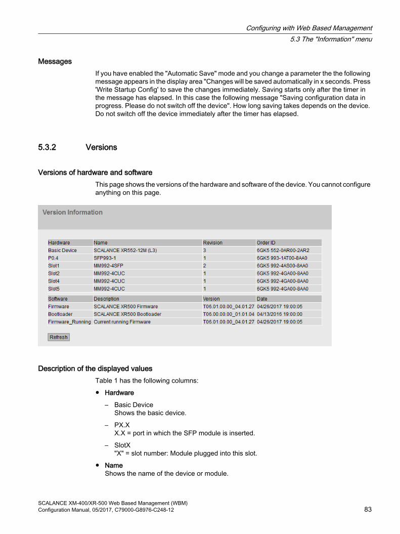
MessagesIf you have enabled the "Automatic Save" mode and you change a parameter the the following message appears in the display area "Changes will be saved automatically in x seconds. Press 'Write Startup Config' to save the changes immediately. Saving starts only after the timer in the message has elapsed. In this case the following message "Saving configuration data in progress. Please do not switch off the device". How long saving takes depends on the device. Do not switch off the device immediately after the timer has elapsed.
5.3.2 Versions
Versions of hardware and software This page shows the versions of the hardware and software of the device. You cannot configure anything on this page.
Description of the displayed valuesTable 1 has the following columns:
● Hardware
– Basic DeviceShows the basic device.
– PX.X X.X = port in which the SFP module is inserted.
– SlotX "X" = slot number: Module plugged into this slot.
● NameShows the name of the device or module.
Configuring with Web Based Management5.3 The "Information" menu
SCALANCE XM-400/XR-500 Web Based Management (WBM)Configuration Manual, 05/2017, C79000-G8976-C248-12 83

● RevisionShows the hardware version of the device.
● Article numberShows the article number of the device or described module.
Table 2 has the following columns:
● Software
– FirmwareShows the current firmware version. If a new firmware file was downloaded and the device has not yet restarted, the firmware version of the downloaded firmware file is displayed here. After the next restart, the downloaded firmware is activated and used.
– BootloaderShows the version of the boot software stored on the device.
● DescriptionShows the short description of the software.
● VersionShows the version number of the software version.
● DateShows the date on which the software version was created.
5.3.3 Identification & Maintenance
Identification and Maintenance dataThis page contains information about device-specific vendor and maintenance data such as the order number, serial number, version number etc. You cannot configure anything on this page.
Configuring with Web Based Management5.3 The "Information" menu
SCALANCE XM-400/XR-500 Web Based Management (WBM)84 Configuration Manual, 05/2017, C79000-G8976-C248-12

Description of the displayed valuesThe table has the following rows:
● Manufacturer IDShows the manufacturer ID.
● Order IDShows the order number.
● Serial NumberShows the serial number.
● Hardware RevisionShows the hardware version.
● Software versionShows the software version.
● Revision CounterRegardless of a version change, this box always displays the value "0".
● Revision DateDate and time of the last revision
● Function tagShows the function tag (plant designation) of the device. The plant designation (HID) is created during configuration of the device with HW Config of STEP 7.
● Location tagShows the location tag of the device. The location identifier (LID) is created during configuration of the device with HW Config of STEP 7.
● DateShows the date created during configuration of the device with HW Config of STEP 7.
● DescriptorShows the description created during configuration of the device with HW Config of STEP 7.
Configuring with Web Based Management5.3 The "Information" menu
SCALANCE XM-400/XR-500 Web Based Management (WBM)Configuration Manual, 05/2017, C79000-G8976-C248-12 85

5.3.4 ARP / Neighbors
5.3.4.1 ARP Table
Assignment of MAC address and IPv4 address With the Address Resolution Protocol (ARP), there is a unique assignment of MAC address to IPv4 address. This assignment is kept by each network node in its own separate ARP table. The WBM page shows the ARP table of the device.
Description of the displayed valuesThe table has the following columns:
● InterfaceShows the interface via which the row entry was learnt.
● MAC AddressShows the MAC address of the destination or source device.
● IP AddressShows the IP address of the destination device.
● Media TypeShows the type of connection.
– DynamicThe device recognized the address data automatically.
– StaticThe addresses were entered as static addresses.
Configuring with Web Based Management5.3 The "Information" menu
SCALANCE XM-400/XR-500 Web Based Management (WBM)86 Configuration Manual, 05/2017, C79000-G8976-C248-12

5.3.4.2 IPv6 Neighbor Table
Assignment of MAC address and IPv6 address Via the IPv6 neighbor table, there is a unique assignment of MAC address to IPv6 address. This assignment is kept by each network node in its own separate neighbor table.
Description of the displayed valuesThe table has the following columns:
● InterfaceDisplays the interface via which the row entry was learnt.
● MAC AddressShows the MAC address of the destination or source device.
● IP AddressShows the IPv6 address of the destination device.
● Media TypeShows the type of connection.
– DynamicThe device recognized the address data automatically.
– StaticThe addresses were entered as static addresses.
5.3.5 Log Table
Logging events The device allows you to log occurring events, some of which you can specify on the page of the "System > Events" menu. This, for example, allows you to record when an authentication attempt failed or when the connection status of a port has changed.
Configuring with Web Based Management5.3 The "Information" menu
SCALANCE XM-400/XR-500 Web Based Management (WBM)Configuration Manual, 05/2017, C79000-G8976-C248-12 87
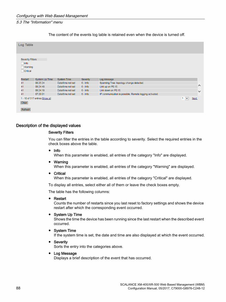
The content of the events log table is retained even when the device is turned off.
Description of the displayed valuesSeverity Filters
You can filter the entries in the table according to severity. Select the required entries in the check boxes above the table.
● InfoWhen this parameter is enabled, all entries of the category "Info" are displayed.
● WarningWhen this parameter is enabled, all entries of the category "Warning" are displayed.
● CriticalWhen this parameter is enabled, all entries of the category "Critical" are displayed.
To display all entries, select either all of them or leave the check boxes empty.
The table has the following columns:
● RestartCounts the number of restarts since you last reset to factory settings and shows the device restart after which the corresponding event occurred.
● System Up TimeShows the time the device has been running since the last restart when the described event occurred.
● System TimeIf the system time is set, the date and time are also displayed at which the event occurred.
● SeveritySorts the entry into the categories above.
● Log MessageDisplays a brief description of the event that has occurred.
Configuring with Web Based Management5.3 The "Information" menu
SCALANCE XM-400/XR-500 Web Based Management (WBM)88 Configuration Manual, 05/2017, C79000-G8976-C248-12

Description of the buttons and input boxes"Clear" button
Click this button to delete the content of the event log file. All entries are deleted regardless of what you have selected under "Severity Filters".
The display is also cleared. The restart counter is only reset after you have restored the device to the factory settings and restarted the device.
Note
The number of entries in this table is restricted to 1200. The table can contain 400 entries for each severity. When this number is reached, the oldest entries of the relevant severity are discarded. The table remains permanently in memory.
"Show all" button
Click this button to display all the entries on the WBM page. Note that displaying all messages can take some time.
"Next" button
Click this button to go to the next page.
"Prev" button
Click this button to go to the previous page.
Drop-down list for page change
From the drop-down list, select the page you want to go to.
"Update" button
Refreshes the display of the values in the table.
5.3.6 Faults
Error status if an error occurs, it is shown on this page. On the device, errors are indicated by red fault LED lighting up.
Internal errors of the device and errors that you configure on the following pages are indicated:
● System > Events"
● "System" > Fault Monitoring"
Errors of the "Cold/Warm Start" event can be deleted by a confirmation.
The calculation of the time of an error always begins after the last system start.
If there are no errors present, the fault LED switches off.
Configuring with Web Based Management5.3 The "Information" menu
SCALANCE XM-400/XR-500 Web Based Management (WBM)Configuration Manual, 05/2017, C79000-G8976-C248-12 89
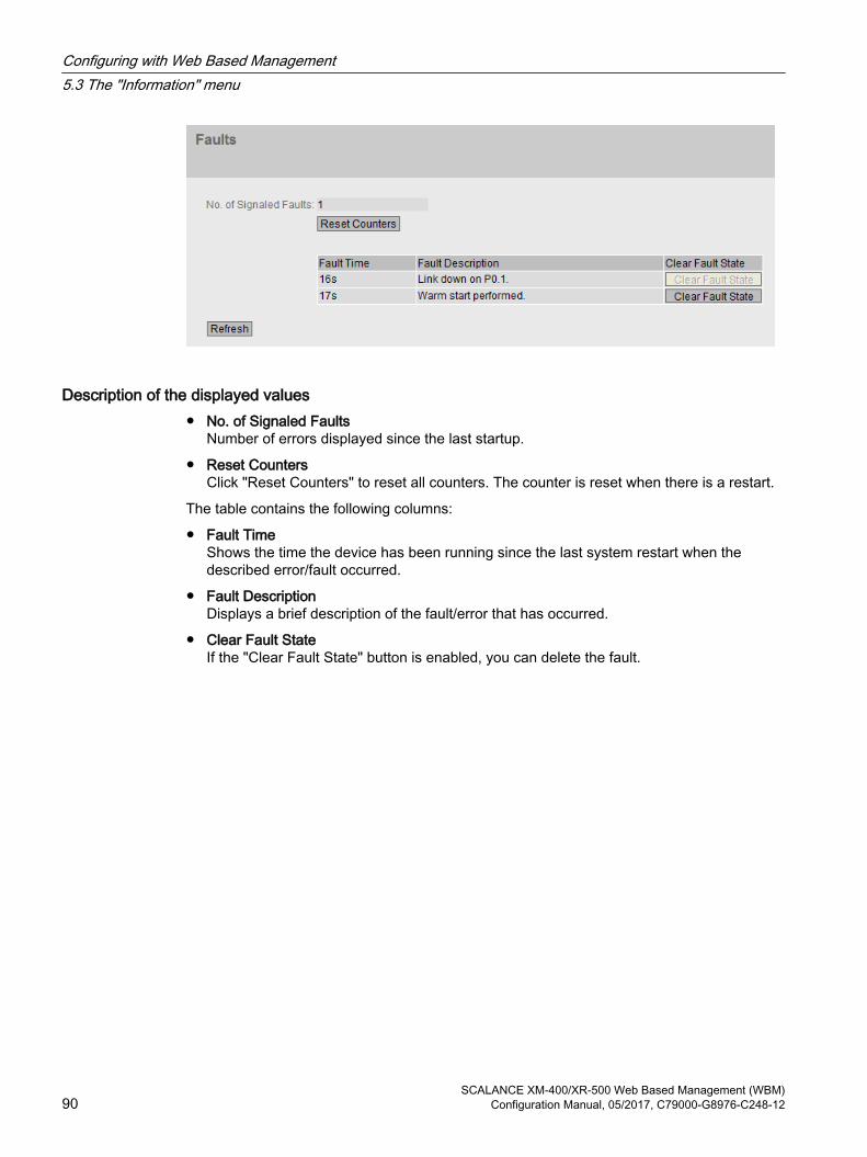
Description of the displayed values● No. of Signaled Faults
Number of errors displayed since the last startup.
● Reset CountersClick "Reset Counters" to reset all counters. The counter is reset when there is a restart.
The table contains the following columns:
● Fault TimeShows the time the device has been running since the last system restart when the described error/fault occurred.
● Fault DescriptionDisplays a brief description of the fault/error that has occurred.
● Clear Fault StateIf the "Clear Fault State" button is enabled, you can delete the fault.
Configuring with Web Based Management5.3 The "Information" menu
SCALANCE XM-400/XR-500 Web Based Management (WBM)90 Configuration Manual, 05/2017, C79000-G8976-C248-12

5.3.7 Redundancy
5.3.7.1 Spanning Tree
Introduction The page shows the current information about the Spanning Tree and the settings of the root bridge.
Description of the displayed valuesThe following fields are displayed:
● Spanning Tree ModeShows the set mode. You specify the mode in "Layer 2 > Configuration" and in "Layer 2 > MSTP > General".The following values are possible:
– '-'
– STP
– RSTP
– MSTP
● Instance IDShows the number of the instance. The parameter depends on the configured mode.
Configuring with Web Based Management5.3 The "Information" menu
SCALANCE XM-400/XR-500 Web Based Management (WBM)Configuration Manual, 05/2017, C79000-G8976-C248-12 91

● Bridge Priority / Root PriorityWhich device becomes the root bridge is decided by the bridge priority. The bridge with the highest priority (in other words, with the lowest value for this parameter) becomes the root bridge. If several devices in a network have the same priority, the device whose MAC address has the lowest numeric value will become the root bridge. Both parameters, bridge priority and MAC address together form the bridge identifier. Since the root bridge manages all path changes, it should be located as centrally as possible due to the delay of the frames. The value for the bridge priority is a whole multiple of 4096 with a range of values from 0 to 32768.
● Bridge Address / Root AddressThe bridge address shows the MAC address of the device and the root address shows the MAC address of the root switch.
● Root CostShows the path costs from the device to the root bridge.
● Bridge StatusShows the status of the bridge, e.g. whether or not the device is the root bridge.
● Regional root priority (available only with MSTP)For a description, see Bridge priority / Root priority
● Regional root address (available only with MSTP)Shows the MAC address of the device.
● Regional Root Cost (available only with MSTP)Shows the path costs from the regional root bridge to the root bridge.
The table has the following columns:
● PortShows the port via which the device communicates. The port is made up of the module number and the port number, for example port 0.1 is module 0, port 1.
● RoleShows the status of the port. The following values are possible:
– DisabledThe port was removed manually from the Spanning Tree and will no longer be taken into account by the Spanning Tree.
– DesignatedThe ports leading away from the root bridge.
– AlternateThe port with an alternative route to a network segment
– BackupIf a switch has several ports to the same network segment, the "poorer" Port becomes the backup port.
– RootThe port that provides the best route to the root bridge.
– MasterThis port points to a root bridge located outside the MST region.
Configuring with Web Based Management5.3 The "Information" menu
SCALANCE XM-400/XR-500 Web Based Management (WBM)92 Configuration Manual, 05/2017, C79000-G8976-C248-12

● StatusDisplays the current status of the port. The values are only displayed. The parameter depends on the configured protocol. The following statuses are possible:
– DiscardingThe port receives BPDU frames. Other incoming or outgoing frames are discarded.
– ListeningThe port receives and sends BPDU frames. The port is involved in the spanning tree algorithm. Other outgoing and incoming frames are discarded.
– LearningThe port actively learns the topology; in other words, the node addresses. Other outgoing and incoming frames are discarded.
– ForwardingFollowing the reconfiguration time, the port is active in the network. The port receives and sends data frames.
● Oper. VersionDescribes the type of spanning tree in which the port operates
● PriorityIf the path calculated by the spanning tree is possible over several ports of a device, the port with the highest priority (in other words the lowest value for this parameter) is selected. A value between 0 and 240 can be entered for the priority in steps of 16. If you enter a value that cannot be divided by 16, the value is automatically adapted. The default is 128.
● Path CostThis parameter is used to calculate the path that will be selected. The path with the lowest value is selected. If several ports of a device have the same value, the port with the lowest port number will be selected.If the value in the "Cost Calc." box is "0", the automatically calculated value is shown. Otherwise, the value of the "Cost Calc." is displayed.The calculation of the path costs is largely based on the transmission speed. The higher the achievable transmission speed is, the lower the value of the path costs.Typical values for path costs with rapid spanning tree:
– 10,000 Mbps = 2,000
– 1000 Mbps = 20,000
– 100 Mbps = 200,000
– 10 Mbps = 2,000,000.
Configuring with Web Based Management5.3 The "Information" menu
SCALANCE XM-400/XR-500 Web Based Management (WBM)Configuration Manual, 05/2017, C79000-G8976-C248-12 93

● Edge TypeShows the type of the connection. The following values are possible:
– Edge PortThere is an end device at this port.
– No Edge PortThere is a Spanning Tree or Rapid Spanning Tree device at this port.
● P.t.P. TypeShows the type of point-to-point link. The following values are possible:
– P.t.P.With half duplex, a point-to-point link is assumed.
–Shared MediaWith a full duplex connection, a point-to-point link is not assumed.
5.3.7.2 VRRP statistics
Introduction This page shows the statistics of the VRRP protocol and all configured virtual routers.
Description of the displayed valuesThe following fields are displayed:
● VRID ErrorsShows how many VRRP packets containing an unsupported VRID were received.
● Version ErrorsShows how many VRRP packets containing an invalid version number were received.
● Checksum ErrorsShows how many VRRP packets containing an invalid checksum were received.
Configuring with Web Based Management5.3 The "Information" menu
SCALANCE XM-400/XR-500 Web Based Management (WBM)94 Configuration Manual, 05/2017, C79000-G8976-C248-12

The table has the following columns:
● InterfaceInterface to which the settings relate.
● VRIDShows the ID of the virtual router. Valid values are 1 to 255.
● Become MasterShows how often this virtual router changed to the "Master" status.
● Advertisements ReceivedShows how often a VRRP packet was received that contained a bad address list.
● Advertisement Interval ErrorsShows how many bad VRRP packets were received whose interval does not match the value set locally.
● IP TTL ErrorsShows how many bad VRRP packets were received whose TTL (Time to live) value in the IP header is incorrect.
● Prio 0 receivedShows how many VRRP packets with priority 0 were received. VRRP packets with priority 0 are sent when a master router is shut down. These packets allow a fast handover to the relevant backup router.
● Prio 0 sentShows how many VRRP packets with priority 0 were sent. Packets with priority 0 are sent when a master router is shut down. These packets allow a fast handover to the relevant backup router.
● Invalid TypeShows how many bad VRRP packets were received whose authentication type was not type 0. Type 0 means "no authentication".
● Address List ErrorsShows how many bad VRRP packets were received whose address list does not match the locally configured list.
Configuring with Web Based Management5.3 The "Information" menu
SCALANCE XM-400/XR-500 Web Based Management (WBM)Configuration Manual, 05/2017, C79000-G8976-C248-12 95

● Invalid Auth. TypeShows how many bad VRRP packets were received whose authentication type does not match.
● Auth. Type MismatchShows that different authentication types are set.
● Packet Length ErrorsShows how many bad VRRP packets were received whose length is not correct.
5.3.7.3 VRRP Statistics
Introduction This page shows the statistics of the VRRPv3 protocol and all configured virtual routers.
Description of the displayed valuesThe following fields are displayed:
● VRID ErrorsShows how many VRRPv3 packets containing an unsupported VRID were received.
● Version ErrorsShows how many VRRPv3 packets containing an invalid version number were received.
● Checksum ErrorsShows how many VRRPv3 packets containing an invalid checksum were received.
The table has the following columns:
● InterfacesInterface to which the settings relate.
● VRIDShows the ID of the virtual router. Valid values are 1 ... 255.
● TypeShows the version of the IP protocol.
Configuring with Web Based Management5.3 The "Information" menu
SCALANCE XM-400/XR-500 Web Based Management (WBM)96 Configuration Manual, 05/2017, C79000-G8976-C248-12

● Become MasterShows how often this virtual router changed to the "Master" status.
● Advertisements ReceivedShows how many VRRPv3 packets were received.
● Advertisement Interval ErrorsShows how many bad VRRPv3 packets were received whose interval does not match the value set locally.
● IP TTL ErrorsShows how many bad VRRPv3 packets were received whose TTL (Time to live) value in the IP header is incorrect.
● Prio 0 receivedShows how many VRRPv3 packets with priority 0 were received. VRRPv3 packets with priority 0 are sent when a master router is shut down. These packets allow a fast handover to the relevant backup router.
● Prio 0 sentShows how many VRRPv3 packets with priority 0 were sent. Packets with priority 0 are sent when a master router is shut down. These packets allow a fast handover to the relevant backup router.
● Invalid TypeShows how many bad VRRPv3 packets were received whose value in the "Type" field of the IP header is invalid.
● Address List ErrorsShows how many bad VRRPv3 packets were received whose address list does not match the locally configured list.
● Packet Length ErrorsShows how many bad VRRPv3 packets were received whose length is not correct.
Configuring with Web Based Management5.3 The "Information" menu
SCALANCE XM-400/XR-500 Web Based Management (WBM)Configuration Manual, 05/2017, C79000-G8976-C248-12 97

5.3.7.4 Ring redundancy
Information on ring redundancyOn this page, you obtain information about the status of the device in terms of ring redundancy. The text boxes on this page are read-only.
Configuring with Web Based Management5.3 The "Information" menu
SCALANCE XM-400/XR-500 Web Based Management (WBM)98 Configuration Manual, 05/2017, C79000-G8976-C248-12

Description of the displayed valuesThe table has the following columns:
● Redundancy FunctionThe "Redundancy Function" column shows the role of the device within the ring:
– No Ring Redundancy (off)The IE switch works without redundancy function.
– HRP ClientThe IE switch operates as an HRP client.
– HRP ManagerThe IE switch operates as an HRP manager.
– MRP ClientThe IE switch operates as an MRP client.
– MRP ManagerThe IE switch operates as an MRP manager. Using STEP 7, the role "Manager" was set for the device.
– MRP Auto-ManagerThe IE switch is operating as an MRP manager. Using WBM or CLI the role "MRP Auto-Manager" or using STEP 7 the role "Manager (Auto)" was set.
● RM StatusThe "RM Status" column shows whether or not the IE switch is operating as redundancy manager and whether it has opened or closed the ring in this role.
– Passive:The IE switch is operating as redundancy manager and has opened the ring; in other words, the line of switches connected to the ring ports is operating problem free. The passive status is also displayed if the IE switch is not operating as the redundancy manager (RM function disabled).
– Active:The IE switch is operating as redundancy manager and has closed the ring; in other words, the line of switches connected to the ring ports is interrupted (problem). The redundancy manager connects its ring ports through and restores an uninterrupted linear topology.
– If media redundancy in ring topologies is completely disabled, ring ports configured last are displayed and the text "Ring Redundancy disabled" is displayed.
● Observer StatusShows the current status of the observer.
● Ring Port 1 and Ring Port 2The "Ring Port 1"and "Ring Port 2" columns show the ports being used as ring ports.
● No. of Changes to RM Active StateShows how often the device as redundancy manager switched to the active status, i.e. closed the ring.If the redundancy function is disabled or the device is an "HRP/MRP client" , the text "Redundancy Manager Disabled" appears.
Configuring with Web Based Management5.3 The "Information" menu
SCALANCE XM-400/XR-500 Web Based Management (WBM)Configuration Manual, 05/2017, C79000-G8976-C248-12 99

● Max. Delay of the RM Test Packets [ms]Shows the maximum delay time of the test frames of the redundancy manager.If the redundancy function is disabled or the device is an "HRP/MRP client" , the text "Redundancy Manager Disabled" appears.
● Click the "Reset Counters" button to reset the counters on this page.
5.3.7.5 Standby
Information on standby redundancyOn this page, you obtain information about the status of the device in terms of standby redundancy. The text boxes on this page are read-only.
NoteDevice with the higher MAC address becomes master
When linking HRP rings redundantly, two devices are always configured as a master/slave pair. This also applies to interrupted HRP rings = linear buses. When operating normally, the device with the higher MAC address adopts the role of master.
This type of assignment is important in particular when a device is replaced. Depending on the MAC addresses, the previous device with the slave function can take over the role of the standby master.
The Standby tab shows the status of the standby function:
Description of the displayed valuesThe table has the following columns:
● Standby PortsShows the standby port.
● Standby NameStandby Connection Name
Configuring with Web Based Management5.3 The "Information" menu
SCALANCE XM-400/XR-500 Web Based Management (WBM)100 Configuration Manual, 05/2017, C79000-G8976-C248-12

● Standby Function
– Master: The device has a connection to the partner device and is operating as master. In normal operation, the standby port of this device is active.
– Slave:The device has a connection to the partner device and is operating as slave. In normal operation, the standby port of this device is inactive.
– Disabled:Standby link is disabled. The device is operating neither as master nor slave. The port configured as a standby port works as a normal port without standby function.
– Waiting for Connection....:No connection has yet been established to the partner device. The standby port is inactive. In this case, either the configuration on the partner device is inconsistent (for example incorrect connection name, standby link disabled) or there is a physical fault (for example device failure, link down).
– Connection Lost: Existing connection to the partner device has been lost. In this case, either the configuration on the partner device was modified (for example a different connection name, standby link disabled) or there is a physical fault (for example device failure, link down).
● Standby StatusThe display box "Standby Status" shows the status of the standby port:
– Active: The standby port of this device is active; in other words is enabled for frame traffic.
– Passive:The standby port of this device is inactive; in other words is blocked for frame traffic.
– "-":The standby function is disabled.
● No. of Changes to Standby Active StateShows how often the IE switch has changed the standby status from "Passive" to "Active". If the connection of a standby port fails on the standby master, the IE switch changes to the "Active" status.If the standby function is disabled, the text "Standby Disabled" appears in this box.Click the "Reset Counters" button to reset the counters on this page.Following each restart on the device, the counters are automatically reset.
5.3.7.6 Link Check
Monitoring optical connections in the ringThe page shows the following information on the link check:
● The ports on which you can enable Link Check
● The current status
● The statistics of sent and received Link Check frames of the monitored connections.
Configuring with Web Based Management5.3 The "Information" menu
SCALANCE XM-400/XR-500 Web Based Management (WBM)Configuration Manual, 05/2017, C79000-G8976-C248-12 101

Description of the displayed valuesThe following fields are displayed:
● PortShows the port to which the following information relates. The port is made up of the module number and the port number, for example port 0.1 is module 0, port 1.
● Link CheckShows whether the Link Check function is enabled or disabled.
● OperStateShows the status of the Link Check function. The following statuses are possible:
– DisabledThe function is disabled.
– EnabledThe function is enabled. The connection partner has not yet confirmed the monitoring.
– RunningThe function is enabled. The connection monitoring is enabled. The outgoing and incoming test frames are counted and matched up.
– FaultsThe function is enabled. Link Check has detected a fault on the monitored section and turned off the port.
● Frames inShows how many Link Check test frames were received.
● Frames outShows how many Link Check test frames were sent
Configuring with Web Based Management5.3 The "Information" menu
SCALANCE XM-400/XR-500 Web Based Management (WBM)102 Configuration Manual, 05/2017, C79000-G8976-C248-12

5.3.8 Ethernet Statistics
5.3.8.1 Interface Statistics
Interface statistics The page shows the statistics from the interface table of the Management Information Base (MIB).
Description of the displayed valuesThe table has the following columns:
● In OctetShows the number of received bytes.
● Out OctetShows the number of sent bytes.
● In UnicastShows the number of received unicast frames.
● In Non UnicastShows the number of received frames that are not of the type unicast.
● Out UnicastShows the number of sent unicast frames.
● Out Non UnicastShows the number of sent frames that are not of the type unicast.
● In ErrorsShows the number of all possible RX errors, refer to the tab "Packet Error".
Description of the button"Reset Counters" button
Click "Reset Counters" to reset all counters. The counters are reset by a restart.
Configuring with Web Based Management5.3 The "Information" menu
SCALANCE XM-400/XR-500 Web Based Management (WBM)Configuration Manual, 05/2017, C79000-G8976-C248-12 103

5.3.8.2 Packet Size
Frames sorted by length This page displays how many frames of which length were sent and received at each port. You cannot configure anything on this page.
The displayed values are transferred by RMON.
On the page "Layer 2 > RMON > Statistics", you can set the ports for which values will be displayed.
Configuring with Web Based Management5.3 The "Information" menu
SCALANCE XM-400/XR-500 Web Based Management (WBM)104 Configuration Manual, 05/2017, C79000-G8976-C248-12

Description of the displayed valuesThe table has the following columns:
● PortShows the available ports and link aggregations. The port is made up of the module number and the port number, for example port 0.1 is module 0, port 1.
NoteDisplay of frame statistics
In the statistics relating to frame lengths, note that both incoming and outgoing frames are counted.
● Frame lengthsThe other columns after the port number contain the absolute numbers of frames according to their frame length.The following frame lengths are distinguished:
– 64 bytes
– 65 - 127 bytes
– 128 - 255 bytes
– 256 - 511 bytes
– 512 - 1023 bytes
– 1024 - Max.
NoteData traffic on blocked ports
For technical reasons, data packets can be indicated on blocked ports.
Description of the button"Reset Counters" button
Click "Reset Counters" to reset all counters. The counters are reset by a restart.
5.3.8.3 Packet Type
Received frames sorted by packet type This page displays how many frames of the type "unicast", "multicast", and "broadcast" were received at each port. You cannot configure anything on this page.
The displayed values are transferred by RMON.
On the page "Layer 2 > RMON > Statistics", you can set the ports for which values will be displayed.
Configuring with Web Based Management5.3 The "Information" menu
SCALANCE XM-400/XR-500 Web Based Management (WBM)Configuration Manual, 05/2017, C79000-G8976-C248-12 105

Description of the displayed valuesThe table has the following columns:
● PortShows the available ports and link aggregations. The port is made up of the module number and the port number, for example port 0.1 is module 0, port 1.
● Unicast / Multicast / BroadcastThe other columns after the port number contain the absolute numbers of the incoming frames according to their packet type "Unicast", "Multicast" and "Broadcast".
Description of the button"Reset Counters" button
Click "Reset Counters" to reset all counters. The counters are reset by a restart.
5.3.8.4 Packet Error
Received bad frames This page shows how many bad frames were received per port. You cannot configure anything on this page.
The displayed values are transferred by RMON.
On the page "Layer 2 > RMON > Statistics", you can set the ports for which values will be displayed.
Configuring with Web Based Management5.3 The "Information" menu
SCALANCE XM-400/XR-500 Web Based Management (WBM)106 Configuration Manual, 05/2017, C79000-G8976-C248-12

Description of the displayed valuesThe table has the following columns:
● PortShows the available ports and link aggregations. The port is made up of the module number and the port number, for example port 0.1 is module 0, port 1.
● Error typesThe other columns after the port number contain the absolute numbers of the incoming frames according to their error type.In the columns of the table, a distinction is made according to the following error types:
–CRCPackets whose content does not match the CRC checksum.
–UndersizePackets with a length less than 64 bytes.
– OversizePackets discarded because they were too long.
– Fragments
Packets with a length less than 64 bytes and a bad CRC checksum.
– JabbersVLAN-tagged packets with an incorrect CRC checksum that were discarded because they were too long.
– CollisionsCollisions that were detected.
Description of the button"Reset Counters" button
Click "Reset Counters" to reset all counters. The counters are reset by a restart.
Configuring with Web Based Management5.3 The "Information" menu
SCALANCE XM-400/XR-500 Web Based Management (WBM)Configuration Manual, 05/2017, C79000-G8976-C248-12 107

5.3.8.5 History
Samples of the statistics The page shows samples from each port with information from the RMON statistics.
On the page "Layer 2 > RMON > History", you can set the ports for which samples will be taken.
Figure 5-2 History
Settings● Port
Select the port for which the history will be displayed.
Description of the displayed values● Entries
Maximum number of samples that can be saved at the same time.
● Interval [s]Interval after which the current status of the statistics will be saved as a sample.
The table has the following columns:
● SampleNumber of the sample
● Sample TimeSystem up time at which the sample was taken.
● UnicastNumber of received unicast frames.
● MulticastNumber of received multicast frames.
Configuring with Web Based Management5.3 The "Information" menu
SCALANCE XM-400/XR-500 Web Based Management (WBM)108 Configuration Manual, 05/2017, C79000-G8976-C248-12

● BroadcastNumber of received broadcast frames.
● CRCNumber of frames with a bad CRC checksum.
● UndersizeNumber of frames that are shorter than 64 bytes.
● OversizeNumber of frames discarded because they were too long.
● FragmentsNumber of frames that are shorter than 64 bytes and have a bad CRC checksum.
● JabbersNumber of frames with a VLAN tag that have a bad CRC checksum and will be discarded because they are too long.
● CollisionsNumber of collisions of received frames.
● Utilization [%]Utilization of the port during a sample.
5.3.9 Unicast
Status of the unicast filter tableThis page shows the current content of the unicast filter table. This table lists the source addresses of unicast address frames. Entries can be made either dynamically when a node sends a frame to a port or statically by the user setting parameters.
Configuring with Web Based Management5.3 The "Information" menu
SCALANCE XM-400/XR-500 Web Based Management (WBM)Configuration Manual, 05/2017, C79000-G8976-C248-12 109

Description of the displayed valuesThis table contains the following columns:
● VLAN IDShows the VLAN-ID assigned to this MAC address.
● MAC AddressShows the MAC address of the node that the device has learned or the user has configured.
● StatusShows the status of each address entry:
– LearntThe specified address was learned by receiving a frame from this node and will be deleted when the aging time expires if no further packets are received from this node.
Note
If there is a link down, learned MAC entries are deleted.
– StaticConfigured by the user. Static addresses are stored permanently; in other words, they are not deleted when the aging time expires or when the switch is restarted.
– OtherThe specified address is learnt indirectly through private VLAN.
● PortShows the port via which the node with the specified address can be reached. Frames received by the device whose destination address matches this address will be forwarded to this port.
5.3.10 Multicast
5.3.10.1 Multicast
Status of the multicast filter tableThis table shows the multicast frames currently entered in the multicast filter table and their destination ports. The entries can be dynamic (the device has learned them) or static (the user has set them).
Note
The device does not learn any reserved multicast addresses, see also RFC 5771.
Configuring with Web Based Management5.3 The "Information" menu
SCALANCE XM-400/XR-500 Web Based Management (WBM)110 Configuration Manual, 05/2017, C79000-G8976-C248-12

Description of the displayed valuesThis table contains the following columns:
● VLAN IDShows VLAN ID of the VLAN to which the MAC multicast address is assigned.
● MAC AddressShows the MAC multicast address that the device has learned or the user has configured.
Configuring with Web Based Management5.3 The "Information" menu
SCALANCE XM-400/XR-500 Web Based Management (WBM)Configuration Manual, 05/2017, C79000-G8976-C248-12 111

● StatusShows the status of each address entry. The following information is possible:
– StaticThe address was entered statically by the user. Static addresses are stored permanently; in other words, they are not deleted when the aging time expires or when the device is restarted. These must be deleted by the user.
– IGMP-SnoopingThe destination port for this address was obtained by IGMP configuration.
– MLDThe destination port for this address was determined by MLD configuration.
– GMRPThe destination port for this address was registered by a received GMRP frame.
● Port ListThere is a column for each slot. Within a column, the multicast group to which the port belongs is shown:
– M(Member) Multicast frames are sent via this port.
– R(Registered) Member of the multicast group, registration was by a GMRP frame.
– I(IGMP/MLD) Member of the multicast group, registration was by an IGMP/MLD frame.
– –Not a member of the multicast group. No multicast frames with the defined multicast MAC address are sent via this port.
– F(Forbidden) Not a member of the multicast group. Moreover, this address may not be an address learned dynamically with GMRP or IGMP/MLD.
5.3.10.2 IGMP Groups
Status of the multicast filter tableThis table shows the multicast groups currently entered in the filter table, configured and joined.
Configuring with Web Based Management5.3 The "Information" menu
SCALANCE XM-400/XR-500 Web Based Management (WBM)112 Configuration Manual, 05/2017, C79000-G8976-C248-12
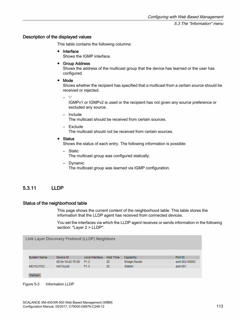
Description of the displayed valuesThis table contains the following columns:
● InterfaceShows the IGMP interface.
● Group AddressShows the address of the multicast group that the device has learned or the user has configured.
● ModeShows whether the recipient has specified that a multicast from a certain source should be received or rejected.
– '-'IGMPv1 or IGMPv2 is used or the recipient has not given any source preference or excluded any source.
– IncludeThe multicast should be received from certain sources.
– ExcludeThe multicast should not be received from certain sources.
● StatusShows the status of each entry. The following information is possible:
– StaticThe multicast group was configured statically.
– DynamicThe multicast group was learned via IGMP configuration.
5.3.11 LLDP
Status of the neighborhood tableThis page shows the current content of the neighborhood table. This table stores the information that the LLDP agent has received from connected devices.
You set the interfaces via which the LLDP agent receives or sends information in the following section: "Layer 2 > LLDP".
Figure 5-3 Information LLDP
Configuring with Web Based Management5.3 The "Information" menu
SCALANCE XM-400/XR-500 Web Based Management (WBM)Configuration Manual, 05/2017, C79000-G8976-C248-12 113
Description of the displayed valuesThis table contains the following columns:
● System NameSystem name of the connected device.
● Device IDDevice ID of the connected device. The device ID corresponds to the device name assigned via PST (STEP 7). If no device name is assigned, the MAC address of the device is displayed.
● Local InterfacePort at which the IE switch received the information.
● Hold TimeAn entry remains stored on the device for the time specified here. If the IE switch does not receive any new information from the connected device during this time, the entry is deleted.
● CapabilityShows the properties of the connected device:
– Router
– Bridge
– Telephone
– DOCSIS Cable Device
– WLAN Access Point
– Repeater
– Station
– Other
● Port IDPort of the device with which the IE switch is connected.
5.3.12 Fiber Monitoring Protocol
Monitoring optical linksWith Fiber Monitoring, you can monitor optical links. The table shows the current status of the ports.
You set the values to be monitored on the following page: "Layer 2 > FMP".
Configuring with Web Based Management5.3 The "Information" menu
SCALANCE XM-400/XR-500 Web Based Management (WBM)114 Configuration Manual, 05/2017, C79000-G8976-C248-12

Description of the displayed valuesPort
Shows the optical ports that support fiber monitoring. This depends on the transceivers.
Rx Power State
● disabledFiber monitoring is disabled.
● okThe value for the received power of the optical link is within the set limits.
● maint. req.Check the link.A warning is signaled.
● maint. dem.The link needs to be checked.An alarm is signaled and the fault LED is lit.
● link downThe connection to the communications partner is down. No link is detected.
Rx Power [dBm]
Shows the current value of the received power. The value can have a tolerance of +/- 3 dB.
If there is no connection (link down) or fiber monitoring is disabled, "-" is displayed. If fiber monitoring is not enabled on the partner port, the value 0.0 is displayed.
Power Loss State
To be able to monitor the power loss of the connection the function fiber monitoring must be enabled for the optical port of the connection partner.
● disabledFiber monitoring is disabled.
● okThe value for the power loss of the optical link is within the defined limits.
● maint. req.Check the link.A warning is signaled.
Configuring with Web Based Management5.3 The "Information" menu
SCALANCE XM-400/XR-500 Web Based Management (WBM)Configuration Manual, 05/2017, C79000-G8976-C248-12 115

● maint. dem.The link needs to be checked.An alarm is signaled and the fault LED is lit.
● idleThe port has no connection to another port with fiber monitoring enabled.If no diagnostics information is received from the optical port of the connection partner for 5 cycles, the fiber monitoring connection is assumed to be interrupted. A cycle lasts 5 seconds.
Power Loss [dB]
Shows the current value of the power loss. The value can have a tolerance of +/- 3 dB.
If there is no connection (link down), fiber monitoring is disabled or the partner port does not support fiber monitoring, "-" is displayed.
5.3.13 IPv4 routing
5.3.13.1 Routing Table
Introduction This page shows the routes currently being used.
Description of the displayed valuesThe table has the following columns:
● Destination NetworkShows the destination address of this route.
● Subnet MaskShows the subnet mask of this route.
● GatewayShows the gateway for this route.
Configuring with Web Based Management5.3 The "Information" menu
SCALANCE XM-400/XR-500 Web Based Management (WBM)116 Configuration Manual, 05/2017, C79000-G8976-C248-12

● InterfaceShows the interface for this route.
● MetricShows the metric of the route. The higher value, the longer packets require to their destination.
● Routing ProtocolShows the routing protocol from which the entry in the routing table originates. The following entries are possible:
– Connected: Connected routes
– Static: Static routes
– RIP: Routes via RIP
– OSPF: Routes via OSPF
– Other: Other routes
5.3.13.2 OSPFv2 Interfaces
OverviewThis page shows the configuration of the OSPF interface.
Description of the displayed valuesThe table has the following columns:
● IP addressShows the IPv4 address of the OSPF interface
● Area IDShows the area ID to which the OSPF interface belongs.
Configuring with Web Based Management5.3 The "Information" menu
SCALANCE XM-400/XR-500 Web Based Management (WBM)Configuration Manual, 05/2017, C79000-G8976-C248-12 117

● Interface StatusShows the status of the WLAN interface:
– DownThe interface is not available.
– Loop backLoop back interface
– WaitingStarting up and negotiating the interface.
– Point to PointPoint-to-point link
– Designated RouterThe router is a designated router and generates network LSAs.
– Backup D. RouterThe router is the backup router for the designated router.
– Other D. RouterThe Interface has started up. The router is neither a designated nor a designated backup router.
● OSPF StatusShows the status of OSPF.
– Enabled: OSPF is enabled on the interface.
– Disabled: OSPF is disabled on the interface.
● Designated RouterShows the IPv4 address of the designated router for this OSPF interface.
● Backup Designated RouterShows the IPv4 address of the designated backup router for this OSPF interface.
● EventsShows the number of status changes of OSPF.
5.3.13.3 OSPFv2 Neighbors
Overview This page shows the dynamically detected neighbor routers in the relevant networks.
Configuring with Web Based Management5.3 The "Information" menu
SCALANCE XM-400/XR-500 Web Based Management (WBM)118 Configuration Manual, 05/2017, C79000-G8976-C248-12

Description of the displayed valuesThe table has the following columns:
● IP AddressShows the IPv4 address of the neighbor router in this network.
● Router IDShows the ID of the neighbor router. The two addresses can match.
● StatusShows the status of the neighbor router. The status can adopt the following values:
– unknownStatus of the neighbor router is unknown.
– downThe neighbor router cannot be reached.
– attempt and initBrief status during initialization
– two-wayTwo-way receipt of Hello packets. Specification of the designated router and the designated backup router.
– exchangestart, exchange and loadingStatus during exchange of the LSAs
– full The database is complete and synchronized within the area. The routes can now be detected.
NoteNormal status
If the partner router is a designated router or a designated backup router, the status is "full". Otherwise the status is "two-way".
● Assoc. Area TypeShows the area type via which the neighbor-neighbor relation is maintained. The following area types exist:
– Standard
– Stub
– NSSA
– Backbone
● PriorityShows the priority of the neighbor router. This is only significant when selecting the designated router on a network. For virtual neighbor routers, this information is irrelevant.
● Hello supprShows the suppressed Hello packets to the neighbor router. This field normally displays "no".
Configuring with Web Based Management5.3 The "Information" menu
SCALANCE XM-400/XR-500 Web Based Management (WBM)Configuration Manual, 05/2017, C79000-G8976-C248-12 119

● Hello QueueShows the length of the queue with Hello packets still to be transmitted.
● EventsShows the number of status changes.
5.3.13.4 OSPFv2 Virtual Neighbors
Overview This page shows the configured virtual neighbors.
Description of the displayed valuesThe table has the following columns:
● IP AddressShows the IPv4 address of the virtual neighbor router in this network.
● Router IDShows the router ID of the virtual neighbor router.
Configuring with Web Based Management5.3 The "Information" menu
SCALANCE XM-400/XR-500 Web Based Management (WBM)120 Configuration Manual, 05/2017, C79000-G8976-C248-12

● StatusShows the status of the neighbor router. The status can adopt the following values:
– unknownStatus of the neighbor router is unknown.
– downThe neighbor router cannot be reached.
– attempt and initBrief status during initialization
– two-wayTwo-way receipt of Hello packets. Specification of the designated router and the designated backup router.
– exchangestart, exchange and loadingStatus during exchange of the LSAs
– full The database is complete and synchronized within the area. The routes can now be detected.
NoteNormal status
If the partner router is a designated router or a designated backup router, the status is "full". Otherwise the status is "two-way".
● Trans. Area IDShows the ID of the area via which the virtual neighborhood relation exists.
● Hello Suppr.Shows whether there are suppressed Hello packets to the virtual neighbor router.
– no: There are no suppressed Hello packets (default)
– yes: There are suppressed Hello packets.
● Hello QueueShows the length of the queue with Hello packets still to be transmitted.
● EventsShows the number of status changes.
Configuring with Web Based Management5.3 The "Information" menu
SCALANCE XM-400/XR-500 Web Based Management (WBM)Configuration Manual, 05/2017, C79000-G8976-C248-12 121

5.3.13.5 OSPFv2 LSDB
Overview The link state database is the central database for managing all links within an area. It consists of the link state advertisements (LSAs). The most important data of these LSAs is shown on the this WBM page.
Configuring with Web Based Management5.3 The "Information" menu
SCALANCE XM-400/XR-500 Web Based Management (WBM)122 Configuration Manual, 05/2017, C79000-G8976-C248-12

Description of the displayed boxesThe table has the following columns:
● Area IDShows the ID of the area to which the LSA belongs. If the LSA is an external connection, '-' is displayed.
● Link State TypeShows the LSA type. The following values are possible:
– UnknownLSA type is unknown.
– RouterThe router LSA (Type 1) is sent by the OSPF router within an area. The LSA contains information about the status of all router interfaces.
– NetworkThe network LSA (Type 2) is sent by the designated router within an area. The LSA contains a list of routers connected to the network.
– NSSA ExternalThe NSSA external LSA (Type 7) is sent by the NSSA-ASBR within an NSSA. The NSSA-ASBR receives LSAs of Type 5 and converts the information to LSAs of Type 7. The NSSA router can forward these LSAs within an NSSA.
– SummaryThe summary LSA (Type 3) is sent by the ABR within an area. The LSA contains information about routes to other networks.
– AS SummaryThe AS summary LSA (Type 4) is sent by the area border router within an area. The LSA contains information about routes to other autonomous systems.
– AS ExternalThe AS external LSA (Type 5) is sent by the AS border router within an autonomous system. The LSA contains information about routes from one network to another.
● Link State IDShows the ID of the LSA.
● Router IDShows the ID of the router that sent this LSA.
● Sequence NumberShows the sequence number of the LSA. Each time an LSA is renewed, this sequence number is incremented by one.
5.3.13.6 RIPv2 Statistics
OverviewThis page shows the statistics of the RIP interface.
Configuring with Web Based Management5.3 The "Information" menu
SCALANCE XM-400/XR-500 Web Based Management (WBM)Configuration Manual, 05/2017, C79000-G8976-C248-12 123

Description of the displayed values
Figure 5-4 RIPv2 Statistics information
The table has the following columns:
● IP AddressShows the IPv4 address of the RIPv2 interface
● Bad packetsNumber of received RIP packets that were deleted and therefore ignored.
● Bad RoutesNumber of routes of valid RIP packets that could not be taken into consideration.
● Updates SentShows how often the router has sent its routing table to its neighbor routers.
5.3.13.7 NAT Translations
OverviewThis page displays the active NAT connections.
Description of the displayed values
Configuring with Web Based Management5.3 The "Information" menu
SCALANCE XM-400/XR-500 Web Based Management (WBM)124 Configuration Manual, 05/2017, C79000-G8976-C248-12

The table has the following columns:
● InterfaceShows the IP interface.
● Inside Local AddressShows the actual address of the device that should be reachable from external.
● Inside Local PortShows the port that is assigned to the Inside Local Address.
● Inside Global AddressShows the address at which the device can be reached from external.
● Inside Global PortShows the port that is assigned to the Inside Global Address.
● Outside Local/Global AddressShows the address of the communications partner.
● Outside Local/Global PortDisplays the port of the external communications partner.
● Last Use Time [s]Shows the time at which the last packet was transferred.
5.3.13.8 PIM interfaces
OverviewThis page shows the PIM interfaces.
Description of the displayed valuesThe table has the following columns:
● InterfaceShows the PIM interface.
● AddressShows the IP address of the interface.
Configuring with Web Based Management5.3 The "Information" menu
SCALANCE XM-400/XR-500 Web Based Management (WBM)Configuration Manual, 05/2017, C79000-G8976-C248-12 125

● Query IntervalEvery PIM router or every PIM interface sends Hello packets cyclically at the specified intervals. This allows every PIM router to get to know its neighbors and the designated router can be specified.
● DR AddressShows the IP address of the designated router.
● DR PriorityShows the DR priority of the interface.
5.3.13.9 PIM Neighbors
OverviewThis page shows the PIM neighborhood table.
Description of the displayed values
The table has the following columns:
● InterfaceShows the PIM interface. The PIM routers are connected together via this interface.
● Neighbor AddressShows the IP address of the neighbor.
● DR PriorityShows the DR priority of the interface.
Configuring with Web Based Management5.3 The "Information" menu
SCALANCE XM-400/XR-500 Web Based Management (WBM)126 Configuration Manual, 05/2017, C79000-G8976-C248-12

5.3.13.10 PIM Routes
OverviewThe page shows the PIM routing table.
Description of the displayed valuesSelect which PIM routes should be displayed.
● All
● Outgoing
Depending on your selection not all columns are displayed in the table.
The table has the following columns:
● Group AddressShows the address of the multicast group.
● Group MaskShows the subnet mask that restricts the multicast band.
● Source Address
– IP AddressShows the source IP address of the multicast packet.
– *(*,G) messages contain the group and the information to pass on the message in the direction of the RP.The route is via the RP.
● Incoming InterfaceShows the interface via which the multicast will be received.
Configuring with Web Based Management5.3 The "Information" menu
SCALANCE XM-400/XR-500 Web Based Management (WBM)Configuration Manual, 05/2017, C79000-G8976-C248-12 127

● Outgoing InterfaceShows the interface via which the multicast will be forwarded.
● StatusShows whether or not a multicast group is used.
– ForwardingThe multicast group is used.
– PrunedThe multicast group is not used.
5.3.13.11 PIM RPs
Samples of the statistics The page shows information on rendezvous points.
Description of the displayed valuesSelect which rendezvous points should be displayed.
● CandidateShows the interfaces of the device that are candidates for rendezvous points.
● Elected (Designated)Shows the designated router of the device.
● StaticShows the static rendezvous points of the device.
Depending on your selection not all columns are displayed in the table.
The table has the following columns:
● Group AddressShows the address of the multicast group.
● Group MaskShows the subnet mask that restricts the multicast band.
Configuring with Web Based Management5.3 The "Information" menu
SCALANCE XM-400/XR-500 Web Based Management (WBM)128 Configuration Manual, 05/2017, C79000-G8976-C248-12

● RP AddressShows the IP address of the RP.
● RP PriorityShows the priority of the interface as RP.
● Bidirectional MulticastShows whether the "bidirectional multicast" functionality is activated or deactivated.
5.3.13.12 PIM BSRs
OverviewThe page shows information on bootstrap routers (BSR).
Description of the displayed valuesThe page contains the following boxes:
● Address of the selected BSRShows the IP address of the BSR that was selected within a PIM network or a PIM domain.
The table has the following columns:
● Candidate BSR AddressShows the interfaces of the device that are candidates for the BSR on the PIM router.
● Candidate BSR PriorityShows the priority of the BSR.
Configuring with Web Based Management5.3 The "Information" menu
SCALANCE XM-400/XR-500 Web Based Management (WBM)Configuration Manual, 05/2017, C79000-G8976-C248-12 129

5.3.13.13 MSDP Cache
OverviewThis page shows the MSDP partners.
Description of the displayed valuesThe table has the following columns:
● SourceShows the source of the multicast.
● GroupShows the multicast group.
● RPShows the MSDP partner.
● UptimeShow the remaining time after which an entry is deleted from the SA cache if no SA cache updates are received.
Configuring with Web Based Management5.3 The "Information" menu
SCALANCE XM-400/XR-500 Web Based Management (WBM)130 Configuration Manual, 05/2017, C79000-G8976-C248-12

5.3.14 IPv6 routing
5.3.14.1 IPv6 Routing Table
Introduction This page shows the IPv6 routes currently being used.
Description of the displayed valuesThe table has the following columns:
● Destination NetworkShows the destination address of this route.
● Prefix LengthShows the prefix length of this route.
● GatewayShows the gateway for this route.
● InterfaceShows the interface for this route.
● MetricShows the metric of the route. The higher value, the longer packets require to their destination.
● Routing ProtocolShows the routing protocol from which the entry in the routing table originates. The following entries are possible:
– connected: Connected routes
– Static: Static routes
– RIPng: Routes via RIPng
– OSPFv3: Routes via OSPFv3
– other: Other routes
Configuring with Web Based Management5.3 The "Information" menu
SCALANCE XM-400/XR-500 Web Based Management (WBM)Configuration Manual, 05/2017, C79000-G8976-C248-12 131

5.3.14.2 OSPFv3 Interfaces
OverviewThis page shows the configuration of the OSPFv3 interface.
Description of the displayed valuesThe table has the following columns:
● InterfaceShows the interface to which the settings relate.
● Area IDShows the Area ID to which the OSPF interface belongs.
● Interface StatusShows the status of the interface.
– DownThe interface is not available.
– Loop backLoop back interface
– WaitingStartup and negotiation of the interface.
– Point to PointPoint-to-point connection
– Designated RouterThe router is a designated router and generates network LSAs.
– Backup D. RouterThe router is the backup router for the designated router.
– S D. RouterThe Interface has started up. The router is neither a designated nor a designated backup router.
Configuring with Web Based Management5.3 The "Information" menu
SCALANCE XM-400/XR-500 Web Based Management (WBM)132 Configuration Manual, 05/2017, C79000-G8976-C248-12

● OSPF StatusShows the status of OSPF.
– Enabled: OSPF is enabled on the interface.
– Disabled: OSPF is disabled on the interface.
● Designated RouterShows the IPv6 address of the designated router for this OSPFv3 interface.
● Backup Designated RouterShows the IPv6 address of the designated backup router for this OSPFv3 interface.
● EventsShows the number of status changes of OSPFv3.
5.3.14.3 OSPFv3 Neighbors
Overview This page shows the dynamically detected neighbor routers in the relevant networks.
Description of the displayed valuesThe table has the following columns:
● InterfaceDisplays the OSPFv3 interface via which the neighbor router can be reached.
● Router IDShows the ID of the neighbor router.
Configuring with Web Based Management5.3 The "Information" menu
SCALANCE XM-400/XR-500 Web Based Management (WBM)Configuration Manual, 05/2017, C79000-G8976-C248-12 133

● StatusShows the status of the neighbor router. The status can adopt the following values:
– unknownStatus of the neighbor router is unknown.
– downThe neighbor router cannot be reached.
– attempt und initShort-lived status during initialization
– two-wayTwo-way receipt of Hello packets. Specification of the designated router and the designated backup router.
– exchangestart, exchange und loadingStatus during exchange of the LSAs
– fullThe database is complete and synchronized within the area. The routes can now be detected.
NoteNormal status
If the partner router is a designated router or a designated backup router, the status is "full". Otherwise the status is "two-way".
● Assoc. Area TypeShows the area type via which the neighbor-neighbor relation is maintained. The following area types exist:
– Standard
– Stub
– NSSA
– Backbone
● PriorityShows the priority of the neighbor router. This is only significant when selecting the designated router on a network. For virtual neighbor routers, this information is irrelevant.
● Hello supprShows the suppressed Hello packets to the neighbor router. This field normally displays "no".
● Hello QueueShows the length of the queue with Hello packets still to be transmitted.
● EventsShows the number of status changes.
Configuring with Web Based Management5.3 The "Information" menu
SCALANCE XM-400/XR-500 Web Based Management (WBM)134 Configuration Manual, 05/2017, C79000-G8976-C248-12

5.3.14.4 OSPFv3 Virtual Neighbors
Overview This page shows the configured virtual neighbors.
Description of the displayed valuesThe table has the following columns:
● InterfaceDisplays the OSPFv3 interface via which the neighbor router can be reached.
● Router IDShows the ID of the virtual neighbor router.
● StatusShows the status of the virtual neighbor router. The status can adopt the following values:
– unknownStatus of the neighbor router is unknown.
– downThe neighbor router cannot be reached.
– attempt und initShort-lived status during initialization
– two-wayTwo-way receipt of Hello packets. Specification of the designated router and the designated backup router.
– exchangestart, exchange und loadingStatus during exchange of the LSAs
– fullThe database is complete and synchronized within the area. The routes can now be detected.
NoteNormal status
If the partner router is a designated router or a designated backup router, the status is "full". Otherwise the status is "two-way".
Configuring with Web Based Management5.3 The "Information" menu
SCALANCE XM-400/XR-500 Web Based Management (WBM)Configuration Manual, 05/2017, C79000-G8976-C248-12 135

● Trans. Area IDShows the ID of the area via which the virtual neighborhood relation exists.
● Hello supprShows the suppressed Hello packets to the neighbor router. This field normally displays "no".
● Hello QueueShows the length of the queue with Hello packets still to be transmitted.
● EventsShows the number of status changes.
5.3.14.5 OSPFv3 AS-Scope LSDB
Overview The AS-Scope LSDB consists of AS external LSAs. The most important data of these LSAs is shown on this page.
Description of the displayed valuesThe table has the following columns:
● Link State Type
– AS ExternalThe AS external LSA (Type 0x4005) is sent by the AS border router within an autonomous system. The LSA contains information about routes from one network to another.
● Link State IDShows the ID of the LSA.
● Router IDShows the ID of the router that sent this LSA.
● Sequence NumberShows the sequence number of the LSA. Each time an LSA is renewed, this sequence number is incremented by one.
Configuring with Web Based Management5.3 The "Information" menu
SCALANCE XM-400/XR-500 Web Based Management (WBM)136 Configuration Manual, 05/2017, C79000-G8976-C248-12

5.3.14.6 OSPFv3 Area-Scope LSDB
Overview The Area-Scope LSDB is the central database for managing all links within an area. The most important data of the LSAs is shown on this page.
Configuring with Web Based Management5.3 The "Information" menu
SCALANCE XM-400/XR-500 Web Based Management (WBM)Configuration Manual, 05/2017, C79000-G8976-C248-12 137

Description of the displayed valuesThe table has the following columns:
● Area IDShows the ID of the area to which the LSA belongs. If the LSA is an external connection, '-' is displayed.
● Link State TypeShows the LSA type. The following values are possible:
– RouterThe router LSA (Type 0x2001) is sent by the OSPF router within an area. The LSA contains information about the status of all router interfaces. However, no longer contains address information. This is contained in the new LSA type 0x2009.
– NetworkThe network LSA (Type 0x2002) is sent by the designated router within an area. The LSA contains a list of routers connected to the network. However, no longer contains address information. This is contained in the new LSA type 2009.
– Inter-Area Prefixthe inter-area prefix LSA (Type 0x2003) is sent by the ABR within an area. The LSA contains information about routes to other networks.
– Inter-Area RouterThe inter-area router LSA (Type 0x2004) is sent by the area border router within an area. The LSA contains information about routes to other autonomous systems.
– NSSAThe NSSA LSA (Type 0x2007) is sent by the NSSA-ASBR within an NSSA. The NSSA-ASBR receives LSAs of Type 0x4005 and converts the information to LSAs of Type 0x2007. The NSSA router can forward these LSAs within an NSSA.
– Intra-Area PrefixThe intra-area prefix LSA (Type 0x2009) is only sent within an area. It contains the IPv6 prefixes connected to the router or network.
● Link State IDShows the ID of the LSA.
● Router IDShows the ID of the router that sent this LSA.
● Sequence NumberShows the sequence number of the LSA. Each time an LSA is renewed, this sequence number is incremented by one.
Configuring with Web Based Management5.3 The "Information" menu
SCALANCE XM-400/XR-500 Web Based Management (WBM)138 Configuration Manual, 05/2017, C79000-G8976-C248-12

5.3.14.7 OSPFv3 Link-Scope LSDB
Overview The link scope LSDB consists of the link LSAs. The most important data of these LSAs is shown on this page.
Description of the displayed valuesThe table has the following columns:
● InterfaceShows the OSPFv3 interface to which the link LSA belongs.
● Link State Type
– LinkThe link LSA (Type 0x2009) is sent by the router to every router linked to it. It contains the link local address of the router and a list with IPv6 prefixes configured on the link.
● Link State IDShows the ID of the LSA.
● Router IDShows the ID of the router that sent this LSA.
● Sequence NumberShows the sequence number of the LSA. Each time an LSA is renewed, this sequence number is incremented by one.
Configuring with Web Based Management5.3 The "Information" menu
SCALANCE XM-400/XR-500 Web Based Management (WBM)Configuration Manual, 05/2017, C79000-G8976-C248-12 139

5.3.14.8 RIPng Statistics
OverviewThis page shows the statistics of the RIPng interfaces.
Figure 5-5 RIPng statistics - Part 1
Description of the displayed valuesThe table has the following columns:
● InterfaceShows the RIPng interface.
● StatusShows the status of the RIPng interface.
– up
– down
● Messages ReceivedShows how often the router has received messages.
● Requests ReceivedShows how often the router has received requests.
● Responses ReceivedShows how often the router has received responses.
● Unknown CommandsShows how many RIPng packets were received whose value in the "Commands" field of the RIPng header is unknown. Known values are 1 for requests and 2 for responses.
Configuring with Web Based Management5.3 The "Information" menu
SCALANCE XM-400/XR-500 Web Based Management (WBM)140 Configuration Manual, 05/2017, C79000-G8976-C248-12

Figure 5-6 RIPng statistics - Part 2
● Other versionShows how many RIPng packets were received whose value in the "Version" field is not 1.
● DiscardsShows how often the router has discarded RIPng packets.
● Messages SentShows how often the router has sent messages.
● Requests SentShows how often the router has sent requests.
● Responses SentShows how often the router has sent responses.
● Updates SentShows how often the router has sent its routing table to its neighbor routers.
5.3.15 DHCP ServerThis page shows which IPv4 addresses were assigned to the devices by the DHCP server.
Description● IP Address
Shows the IPv4 address assigned to the DHCP client.
● Pool IDShows the number of the IPv4 address band.
Configuring with Web Based Management5.3 The "Information" menu
SCALANCE XM-400/XR-500 Web Based Management (WBM)Configuration Manual, 05/2017, C79000-G8976-C248-12 141

● Identification methodShows the method according to which the DHCP client is identified.
● Identification valueShows the MAC address ot he client ID of the DHCP client.
● Remote IDShows the remote ID of the DHCP client.
● Circuit IDShows the circuit ID of the DHCP client.
● Allocation MethodShows whether the IPv4 address was assigned statically or dynamically. You configure the static entries in "System > DHCP > Static Leases".
● Binding StateShows the status of the assignment.
– AssignedThe assignment is used.
– Not usedThe assignment is not used.
– ProbingThe assignment is being checked.
– UnknownThe status of the assignment is unknown.
● Expire TimeShows until when the assigned IPv4 address is still valid. Up to this time, the DHCP client must either request a new IPv4 address or extend the lease time of the assigned IPv4 address.
Description of the buttons and input boxes"Show all" button
Click this button to display all the entries on the WBM page. Note that displaying all messages can take some time.
"Next" button
Click this button to go to the next page.
"Prev" button
Click this button to go to the previous page.
Drop-down list for page change
From the drop-down list, select the page you want to go to.
"Refresh" button
Refreshes the display of the values in the table.
Configuring with Web Based Management5.3 The "Information" menu
SCALANCE XM-400/XR-500 Web Based Management (WBM)142 Configuration Manual, 05/2017, C79000-G8976-C248-12

5.3.16 SNMPThis page displays the created SNMPv3 groups. You configure the SNMPv3 groups in "System" > SNMP".
DescriptionThe table has the following columns:
● Group NameShows the group name.
● User NameShows the user that is assigned to the group.
5.3.17 Security
5.3.17.1 Overview
Note
The values displayed depend on the rights of the logged-on user.
This page shows the security settings and the local and external user accounts.
Configuring with Web Based Management5.3 The "Information" menu
SCALANCE XM-400/XR-500 Web Based Management (WBM)Configuration Manual, 05/2017, C79000-G8976-C248-12 143

DescriptionServices
The "Services" list shows the security settings.
● Telnet ServerYou configure the setting in "System > Configuration".
– Enabled: Unencrypted access to the CLI.
– Disabled: No unencrypted access to the CLI.
● SSH ServerYou configure the setting in "System > Configuration".
– Enabled: Encrypted access to the CLI.
– Disabled: No encrypted access to the CLI.
● Web ServerYou configure the setting in "System > Configuration".
– HTTP/HTTPS: Access to the WBM is possible with HTTP and HTTPS.
– HTTPS: Access to the WBM is now only possible with HTTPS.
Configuring with Web Based Management5.3 The "Information" menu
SCALANCE XM-400/XR-500 Web Based Management (WBM)144 Configuration Manual, 05/2017, C79000-G8976-C248-12

● SNMPYou can configure setting in "System > SNMP > General".
– "-" (SNMP disabled)Access to device parameters via SNMP is not possible.
– SNMPv1/v2c/v3Access to device parameters is possible with SNMP versions 1, 2c or 3.
– SNMPv3Access to device parameters is possible only with SNMP version 3.
● Management ACLYou configure the setting in "Security > Management ACL".
– Enabled: Restricted access only: Access is restricted using an Access Control List (ACL).
– Disabled: No access restriction: Management ACL is not enabled.
– Enabled: No access restriction: Management ACL is enabled, but access is not restricted using an Access Control List (ACL).
● Login AuthenticationYou configure the setting in "Security > AAA > General".
– LocalThe authentication must be made locally on the device.
– RADIUSThe authentication must be handled via a RADIUS server.
– Local and RADIUSThe authentication is possible both with the users that exist on the device (user name and password) and via a RADIUS server.The user is first searched for in the local database. If the user does not exist there, a RADIUS query is sent.
– RADIUS and fallback localThe authentication must be handled via a RADIUS server.A local authentication is performed only when the RADIUS server cannot be reached in the network.
● Password PolicyShows which password policy is currently being used.
Local and external user accounts
You configure local user accounts and roles in "Security > User Accounts"
When you create a local user account an external user account is generated automatically.
Local user accounts involve users each with a password for logging in on the device.
In the table "External User Accounts" a user is linked to a role. In this example the user "Observer" is linked to the "user" role. The user is defined on a RADIUS server. The roll is defined locally on the device. When a RADIUS server authenticates a user, the corresponding group however is unknown or does not exist, the device checks whether or not there is an entry for the user in the table "External User Accounts". If an entry exists, the user is logged
Configuring with Web Based Management5.3 The "Information" menu
SCALANCE XM-400/XR-500 Web Based Management (WBM)Configuration Manual, 05/2017, C79000-G8976-C248-12 145

in with the rights of the associated role. If the corresponding group is known on the device, both tables are evaluated. The user is assigned the role with the higher rights.
Note
The table "External User Accounts" is only evaluated if you have set "SiemensVSA" in the RADIUS Authorization Mode".
With CLI you can access external user accounts.
The table "Local User Accounts" has the following columns:
● User AccountShows the name of the local user.
● RoleShows the role of the user. You can obtain more information on the function rights of the role in "Information > Security > Roles".
The table "External User Accounts" has the following columns:
● User AccountShows the name of the user on the RADIUS server.
● RoleShows the role assigned to the user on the device. You can obtain more information on this in "Information > Security > Roles".
5.3.17.2 Supported Function Rights
Note
The values displayed depend on the role of the logged-on user.
The page shows the function rights available locally on the device.
Configuring with Web Based Management5.3 The "Information" menu
SCALANCE XM-400/XR-500 Web Based Management (WBM)146 Configuration Manual, 05/2017, C79000-G8976-C248-12

Description of the displayed values● Function Right
Shows the number of the function right. Different rights relating to the device parameters are assigned to the numbers.
● DescriptionShows the description of the function right.
5.3.17.3 Roles
Note
The values displayed depend on the role of the logged-on user.
The page shows the roles valid locally on the device.
Description of the displayed valuesThis table contains the following columns:
● RoleShows the name of the role.
● Function RightShows the function right of the role:
– 1Users with this role can read device parameters but cannot change them.
– 15Users with this role can both read and change device parameters.
– 0This is a role that the device assigns internally when a user could not be authenticated. The user is denied access to the device.
● DescriptionShows a description of the role.
Configuring with Web Based Management5.3 The "Information" menu
SCALANCE XM-400/XR-500 Web Based Management (WBM)Configuration Manual, 05/2017, C79000-G8976-C248-12 147

5.3.17.4 Groups
Note
The values displayed depend on the role of the logged-on user.
This page shows which group is linked to which role. The group is defined on a RADIUS server. The roll is defined locally on the device.
Description of the displayed valuesThe table has the following columns:
● GroupShows the name of the group. The name matches the group on the RADIUS server.
● RoleShows the name of the role. Users who are authenticated with the linked group on the RADIUS server receive the rights of this role locally on the device.
● DescriptionShows a a description for the link.
5.4 The "System" menu
5.4.1 Configuration
System configuration The WBM page contains the configuration overview of the access options of the device.
Specify the services that access the device. With some services, there are further configuration pages on which more detailed settings can be made.
Configuring with Web Based Management5.4 The "System" menu
SCALANCE XM-400/XR-500 Web Based Management (WBM)148 Configuration Manual, 05/2017, C79000-G8976-C248-12

Description of the displayed boxesThe page contains the following boxes:
● Telnet ServerEnable or disable the "Telnet Server" service for unencrypted access to the CLI.
● SSH ServerEnable or disable the "SSH Server" service for encrypted access to the CLI.
● HTTPS Server onlyIf this function is enabled, you can only access the device via HTTPS.
● DNS ClientEnable or disable depending on whether the IE switch should operate as a DNS client. You can configure other settings in "System > DNS".
● SMTP ClientEnable or disable the SMTP client. You can configure other settings in "System > SMTP Client".
● Syslog ClientEnable or disable the Syslog client. You can configure other settings in "System > Syslog Client".
Configuring with Web Based Management5.4 The "System" menu
SCALANCE XM-400/XR-500 Web Based Management (WBM)Configuration Manual, 05/2017, C79000-G8976-C248-12 149

● DCP Server Specify whether or not the device can be accessed with DCP (Discovery and Configuration Protocol):
– "-" (disabled)DCP is disabled. Device parameters can neither be read nor modified.
– Read/WriteWith DCP, device parameters can be both read and modified.
– Read OnlyWith DCP, device parameters can be read but cannot be modified.
● RCDP Server Specify whether or not the device can be accessed with RCDP (RUGGEDCOM Discovery Protocol):
– "-" (deactivated)RCDP is deactivated. Device parameters can neither be read nor modified.
– Read/WriteWith RCDP, device parameters can be both read and modified.
– Read OnlyWith RCDP, device parameters can be read but cannot be modified.
If RCDP is configured accordingly on the device, you can access the device with the RUGGEDCOM EXPLORER via out-of-band interface.
● Time SettingSelect the setting from the drop-down list. The following settings are possible:
– ManualThe system time is set manually. You can configure other settings in "System > System Time > Manual Setting".
– SIMATIC TimeThe system time is set using a SIMATIC time transmitter. You can configure other settings in "System > System Time > SIMATIC Time Client".
– SNTP ClientThe system time is set via an SNTP server. You can configure other settings in "System > System Time > SNTP Client".
– NTP ClientThe system time is set via an NTP server. You can configure other settings in "System > System Time > NTP Client".
– PTP Client(SCALANCE XR528-6M and XR552-12M only)The system time is set via a PTP. You can configure other settings in "System > System Time > PTP Client".
Configuring with Web Based Management5.4 The "System" menu
SCALANCE XM-400/XR-500 Web Based Management (WBM)150 Configuration Manual, 05/2017, C79000-G8976-C248-12

● SNMPSelect the protocol from the drop-down list. The following settings are possible:
– "-" (SNMP disabled)Access to device parameters via SNMP is not possible.
– SNMPv1/v2c/v3Access to device parameters is possible with SNMP versions 1, 2c or 3. You can configure other settings in "System > SNMP > General".
– SNMPv3Access to device parameters is possible only with SNMP version 3. You can configure other settings in "System > SNMP > General".
● SNMPv1/v2 Read-OnlyEnable or disable write access to SNMP variables with SNMPv1/v2c.
● SNMPv1 TrapsEnable or disable the sending of traps (alarm frames). You can configure other settings in "System > SNMP > Traps".
● SINEMA configuration interfaceIf the SINEMA configuration interface is enabled, you can download configurations to the IE switch via the TIA Portal.
● NFC(only for SCALANCE XM-400)Activate or deactivate the "NFC" (Near Field Communication) function. You will find further information on NFC in the "SCALANCE XM400" Operating Instructions.
● Configuration Mode Select the mode from the drop-down list. The following modes are possible:
– Automatic SaveAutomatic backup mode. Approximately 1 minute after the last parameter change or when you restart the device, the configuration is automatically saved.
– TrialTrial mode. In Trial mode, although changes are adopted, they are not saved in the configuration file (startup configuration). To save changes in the configuration file, use the "Write startup config" button. The "Write startup config" button is displayed when you set trial mode. The display area also shows the message "Trial Mode Active – Press "Write Startup Config" button to make your settings persistent" as soon as there are unsaved modifications. This message can be seen on every WBM page until the changes made have either been saved or the device has been restarted.
Steps in configuration 1. To use the required function, select the corresponding check box.
2. Select the options you require from the drop-down lists.
3. Click the "Set Values" button.
Configuring with Web Based Management5.4 The "System" menu
SCALANCE XM-400/XR-500 Web Based Management (WBM)Configuration Manual, 05/2017, C79000-G8976-C248-12 151

5.4.2 General
5.4.2.1 Device
General device information This page contains the general device information.
The boxes "Current System Time", "System Up Time" and "Device Type" cannot be changed.
DescriptionThe page contains the following boxes:
● Current System TimeShows the current system time. The system time is either set by the user or by a time-of-day frame: either SINEC H1 time-of-day frame, NTP or SNTP. (readonly)
● System Up TimeShows the operating time of the device since the last restart. (readonly)
● Device Type Shows the type designation of the device. (readonly)
● System NameYou can enter the name of the device. The entered name is displayed in the selection area. A maximum of 255 characters are possible. The system name is also displayed in the CLI input prompt. The number of characters in the CLI input prompt is limited. The system name is truncated after 16 characters.
Configuring with Web Based Management5.4 The "System" menu
SCALANCE XM-400/XR-500 Web Based Management (WBM)152 Configuration Manual, 05/2017, C79000-G8976-C248-12
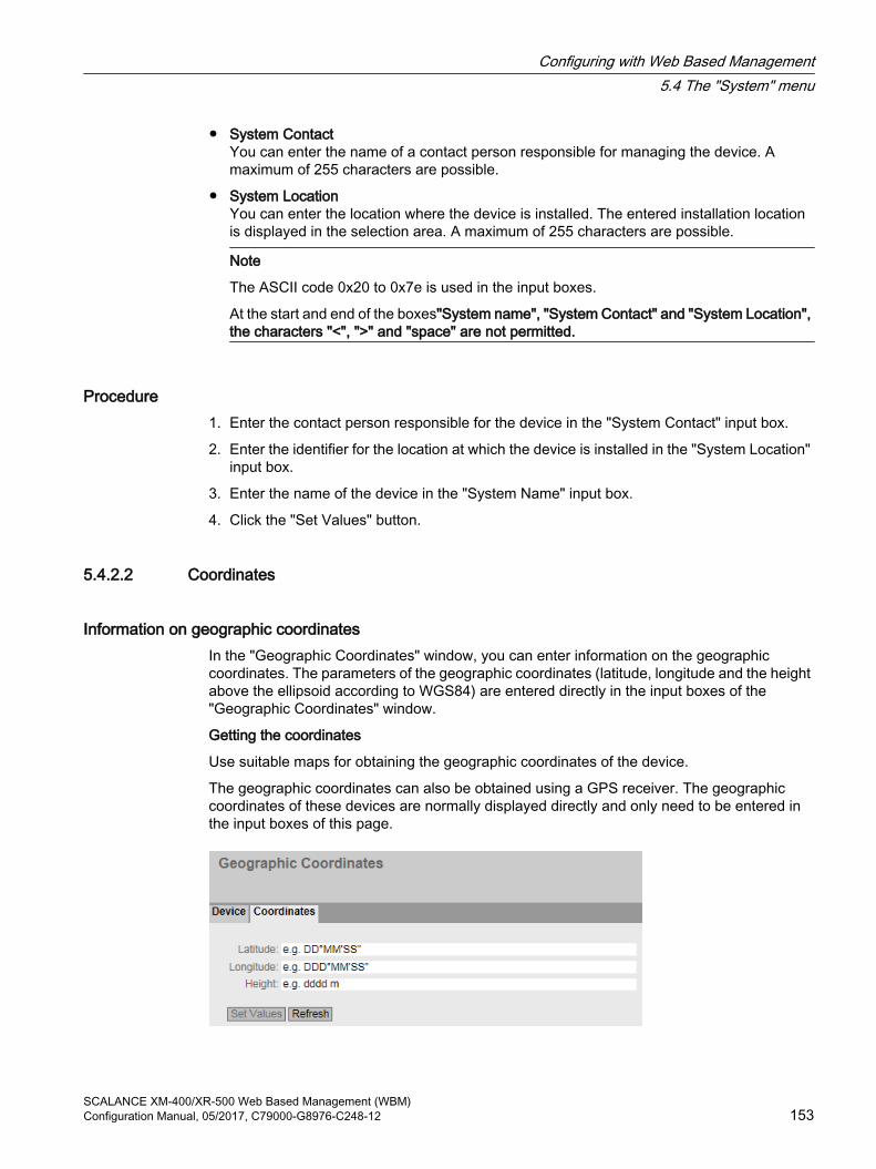
● System ContactYou can enter the name of a contact person responsible for managing the device. A maximum of 255 characters are possible.
● System LocationYou can enter the location where the device is installed. The entered installation location is displayed in the selection area. A maximum of 255 characters are possible.
Note
The ASCII code 0x20 to 0x7e is used in the input boxes.
At the start and end of the boxes"System name", "System Contact" and "System Location", the characters "<", ">" and "space" are not permitted.
Procedure1. Enter the contact person responsible for the device in the "System Contact" input box.
2. Enter the identifier for the location at which the device is installed in the "System Location" input box.
3. Enter the name of the device in the "System Name" input box.
4. Click the "Set Values" button.
5.4.2.2 Coordinates
Information on geographic coordinates In the "Geographic Coordinates" window, you can enter information on the geographic coordinates. The parameters of the geographic coordinates (latitude, longitude and the height above the ellipsoid according to WGS84) are entered directly in the input boxes of the "Geographic Coordinates" window.
Getting the coordinates
Use suitable maps for obtaining the geographic coordinates of the device.
The geographic coordinates can also be obtained using a GPS receiver. The geographic coordinates of these devices are normally displayed directly and only need to be entered in the input boxes of this page.
Configuring with Web Based Management5.4 The "System" menu
SCALANCE XM-400/XR-500 Web Based Management (WBM)Configuration Manual, 05/2017, C79000-G8976-C248-12 153

DescriptionThe page contains the following boxes. These are purely information boxes with a maximum length of 32 characters.
● "Latitude" input boxGeographical latitude: Here, enter the value for the northerly or southerly latitude of the location of the device.For example, the value +49° 1´31.67" means that the device is located at 49 degrees, 1 arc minute and 31.67 arc seconds northerly latitude.A southerly latitude is shown by a preceding minus character.You can also append the letters N (northerly latitude) or S (southerly latitude) to the numeric information (49° 1´31.67" N).
● "Longitude" input boxGeographic longitude: Here, you enter the value of the eastern or western longitude of the location of the device.The value +8° 20´58.73" means that the device is located at 8 degrees, 20 minutes and 58.73 seconds east.A western longitude is indicated by a preceding minus sign.You can also add the letter E (easterly longitude) or W (westerly longitude) to the numeric information (8° 20´58.73" E).
● Input box: "Height"Height Here, you enter the value of the geographic height above sea level in meters.For example, 158 m means that the device is located at a height of 158 m above sea level.Heights below sea level (for example the Dead Sea) are indicated by a preceding minus sign.
Procedure1. Enter the calculated latitude in the "Latitude" input box.
2. Enter the calculated longitude in the "Longitude" input box.
3. Enter the height above sea level in the "Height" input box.
4. Click the "Set Values" button.
5.4.3 Agent IPHere, you specify the IP configuration for the device.
With devices with more than one IP interface, this call references the "Subnets > Configuration" menu item in the "Layer 3" menu and the configuration of the TIA interface there.
5.4.4 DNSOn this page, you can manuall configure up to 3 DNS servers with IPv4 or IPv6 addresses. Manually configured DNS servers are each assigned an index from 1 to 3. Using DHCP the IE switch can learn 2 DNS servers with IPv4 addresses. Learned DNS servers are automatically assigned an index from 6 to 7.
Configuring with Web Based Management5.4 The "System" menu
SCALANCE XM-400/XR-500 Web Based Management (WBM)154 Configuration Manual, 05/2017, C79000-G8976-C248-12

If there is more than one DNS server, the order in the table specifies the order in which the servers are queried. The top server is queried first. In total 5 DNS servers can be configured on the IE switch. Manually configured DNS servers are given preference.
The DNS () server (Domain Name System) assigns a domain name to an IP address so that a device can be uniquely identified.
If this function is enabled, the IE switch can communicate with a DNS server as a DNS client. You have the option of entering names in IP address boxes.
Note
The DNS client function can only be used if there is a DNS server in the network.
Description
Figure 5-7 DNS client
The page contains the following boxes:
● DNS ClientEnable or disable depending on whether the IE switch should operate as a DNS client.
● Used DNS ServersHere you specify which DNS server the device uses:
– learned onlyThe device uses only the DNS servers assigned by DHCP.
– Manual onlyThe device uses only the manually configured DNS servers. The DNS servers must be connected to the Internet. A maximum of three DNS servers can be configured.
– AllThe device uses all available DNS servers.
● DNS Server AddressEnter the IP address of the DNS server.
Configuring with Web Based Management5.4 The "System" menu
SCALANCE XM-400/XR-500 Web Based Management (WBM)Configuration Manual, 05/2017, C79000-G8976-C248-12 155

This table contains the following columns:
● SelectSelect the check box in the row to be deleted.
● DNS Server AddressShows the IP address of the DNS server.
● OriginThis shows whether the DNS server was configured manually or was assigned by DHCP.
ProcedureActivating DNS
1. Enable the "DNS-Client" check box.
2. Click the "Set Values" button.
Creating a DNS server
1. In the "DNS Server Address" box, enter the IP address of the DNS server.
2. Click the "Create" button.
Filtering DNS servers
1. In the "Used DNS Servers" drop-down list, select which DNS servers are to be used.
2. Click the "Set Values" button.
5.4.5 Restart
Resetting to the defaults In this menu, there is a button with which you can restart the device and the option of resetting to the factory setting or reset the default settings of various profiles.
Configuring with Web Based Management5.4 The "System" menu
SCALANCE XM-400/XR-500 Web Based Management (WBM)156 Configuration Manual, 05/2017, C79000-G8976-C248-12

RestartNote the following points about restarting a device:
● You can only restart the device with administrator privileges.
● A device should only be restarted with the buttons of this menu or with the appropriate CLI commands and not by a power cycle on the device.
● If the device is in "Trial" mode, configuration modifications must be saved manually before a restart. Any modifications you have made only become active on the device after clicking the "Set values" button on the relevant WBM page.
● If the device is in "Automatic Save" mode, the last changes are saved automatically before a restart.
Reset to Factory DefaultsBy resetting all the settings to the factory settings, the IP address and the passwords are also lost. Following this, the device can only be accessed via the serial interface, using the Primary Setup Tool or using DHCP.
NOTICE
With the appropriate attachment, a previously correctly configured device can cause circulating frames after the reset and therefore the failure of the data traffic.
Resetting to defaults (profiles)The profiles provide a preconfiguration for various use cases of the devices.
When you start a device with the default settings of a profile, the settings are reset to the factory settings and some parameters are set so that they are designed for a certain use case. In contrast to resetting to the factory settings. the users and passwords are retained after the restart. The configured IP address is lost so that device can then only be accessed via the serial interface, using the Primary Setup Tool or using DHCP.
NOTICE
With the appropriate attachment, a previously correctly configured device can cause circulating frames after the reset and therefore the failure of the data traffic.
Which settings were set specially for a profile are displayed before the restart.
The profiles can be used independently of the factory setting of the device.
Description of the displayed boxes
Note
Note the effects of the individual functions described in the sections above.
Configuring with Web Based Management5.4 The "System" menu
SCALANCE XM-400/XR-500 Web Based Management (WBM)Configuration Manual, 05/2017, C79000-G8976-C248-12 157

To restart the device, the buttons on this page provide you with the following options:
● RestartClick this button to restart the system. You must confirm the restart in a dialog box. During a restart, the device is reinitialized, the internal firmware is reloaded, and the device runs a self-test. The settings of the start configuration are retained, e.g. the IP address of the device. The learned entries in the address table are deleted. You can leave the browser window open while the device restarts. After the restart you will need to log in again.
● Restore Factory Defaults and Restart Click this button to restore the factory defaults of the device and to restart the device. You must confirm the restart in a dialog box.The factory defaults depend on the device.
To restart the device with a predefined profile, the buttons on this page provide you with the following options:
● PROFINET DefaultsClick this button to restore the default settings of the PROFINET profile and to restart the device. You must confirm the restart in a dialog box. The dialog box displays the settings specially made for operation with the PROFINET protocol.
● EtherNet/IP DefaultsClick this button to restore the default settings of the EtherNet/IP profile and to restart the device. You must confirm the restart in a dialog box. The dialog box displays these settings specially made for operation with the EtherNet/IP protocol.
● Industrial Ethernet DefaultsClick this button to restore the default settings of the Industrial Ethernet profile and to restart the device. You must confirm the restart in a dialog box. The dialog box displays these settings specially made for operation in the Industrial Ethernet environment.
5.4.6 Load & Save
Overview of the file types
File type DescriptionConfig This file contains the start configuration.
Among other things, this device contains the definitions of the users, roles, groups and function rights. The passwords are stored the file "Users".
ConfigPack Detailed configuration information. for example, start configuration, users, cer‐tificatesZIP file consisting of the Config, Users and LSYS fle.
ConfigPackBackup This ZIP file stores all the configuration backups you have created.Debug This file contains information for Siemens Support.
It is encrypted and can be sent by e-mail to Siemens Support without any security risk.
DebugExt This file contains detailed information for Siemens Support.It is encrypted and can be sent by e-mail to Siemens Support without any security risk. Saving the file may take some time.
Configuring with Web Based Management5.4 The "System" menu
SCALANCE XM-400/XR-500 Web Based Management (WBM)158 Configuration Manual, 05/2017, C79000-G8976-C248-12

File type DescriptionEDS Electronic Data Sheet (EDS)
Electronic data sheets for describing devices in the EtherNet/IP modeFirmware The firmware is signed and encrypted. This ensures that only firmware created
by Siemens can be downloaded to the device.GSDML PROFINET information on the device propertiesHTTPSCert Default HTTPS certificates including key
The preset and automatically created HTTPS certificates are self-signed.We strongly recommend that you create your own HTTPS certificates and make them available. We recommend that you use HTTPS certificates signed either by a reliable external or by an internal certification authority. The HTTPS certifi‐cate checks the identity of the device and controls the encrypted data exchange.Certificates with a different format cannot be copied in.
LogFile File with entries from the event log tableMIB Private MSPS MIB fileRunningCLI Text file with CLI commands
This file contains an overview of the current configuration in the form of CLI commands. Passwords are masked in this file as follows: [PASSWORD]You can download the text file. The file is not intended to be uploaded again unchanged.
Script Text file with CLI commandsYou can upload a script file in a device. The CLI commands it contains are executed appropriately.
StartupInfo Startup log fileThis file contains the messages that were entered in the log during the last start‐up.
Users This file contains the assignment of the user names to the corresponding pass‐words.
WBMFav WBM favorite pagesThis file contains the favorites that you created in the WBM.. You can download this file and upload it in other devices.
5.4.6.1 HTTP
Loading and saving data via HTTPThe WBM allows you to store device data in an external file on your client PC or to load such data from an external file from the client PC to the devices. This means, for example, that you can also load new firmware from a file located on your client PC.
Note
This WBM page is available both for connections using HTTP and for connections using HTTPS.
Firmware
Configuring with Web Based Management5.4 The "System" menu
SCALANCE XM-400/XR-500 Web Based Management (WBM)Configuration Manual, 05/2017, C79000-G8976-C248-12 159

The firmware is signed and encrypted. This ensures that only firmware created by Siemens can be downloaded to the device.
NoteIncompatibility with previous firmware versions with/without PLUG inserted
During the installation of a previous version, the configuration data can be lost. In this case, the device starts up with the factory settings after the firmware has been installed.
In this situation, if a PLUG is inserted in the device, following the restart, this has the status "Not Accepted" since the PLUG still has the configuration data of the previous more up-to-date firmware. This allows you to return to the previous, more up-to-date firmware without any loss of configuration data. If the original configuration on the PLUG is no longer required, the PLUG can be deleted or rewritten manually using the WBM page "System > PLUG".
Configuration files
NoteConfiguration files and trial mode/Automatic Save mode
In Automatic Save mode, the data is saved automatically before the configuration files (ConfigPack and Config) are transferred.In Trial mode, although the changes are adopted, they are not saved in the configuration files (ConfigPack and Config). Use the "Write Startup Config" button on the "System > Configuration" WBM page to save changes in the configuration files.
CLI script file
You can download existing CLI configurations (RunningCLI) and upload your own CLI scripts (Script).
Note
The downloadable CLI script is not intended to be uploaded again unchanged.
Configuring with Web Based Management5.4 The "System" menu
SCALANCE XM-400/XR-500 Web Based Management (WBM)160 Configuration Manual, 05/2017, C79000-G8976-C248-12

Description of the displayed boxesThe table has the following columns:
● TypeShows the file type.
● DescriptionShows the short description of the file type.
● LoadWith this button, you can upload files to the device. The button can be enabled, if this function is supported by the file type.
● SaveWith this button, you can download files from the device. The button can only be enabled if this function is supported by the file type and the file exists on the device.
● DeleteWith this button, you can delete files from the device. The button can only be enabled if this function is supported by the file type and the file exists on the device.
Note
Following a firmware update, delete the cache of your Internet browser.
Configuring with Web Based Management5.4 The "System" menu
SCALANCE XM-400/XR-500 Web Based Management (WBM)Configuration Manual, 05/2017, C79000-G8976-C248-12 161

Steps in configuration
Uploading files using HTTP1. Start the upload function by clicking the one of the "Load" buttons.
A dialog for uploading a file opens.
2. Select the required file and confirm the upload.The file is uploaded.
3. If a restart is necessary, a message to this effect will be output. Click the "OK" button and a restart will follow. If you click the "Abort" button, there is no device restart. The changes only take effect after a restart.
Downloading files using HTTP1. Start the download by clicking the one of the "Save" buttons.
2. Select a storage location and a name for the file.
3. Save the file.The file is downloaded and saved.
Deleting files using HTTP
1. Start the delete function by clicking the one of the "Delete" buttons.The file is deleted.
Reusing configuration data
If several devices are to receive the same configuration and the IP addresses are assigned using DHCP, the effort for configuration can be reduced by saving and reading in the configuration data.
Follow the steps below to reuse configuration data:
1. Save the configuration data of a configured device on your PC.
2. Load this configuration file on all other devices you want to configure in this way.
3. If individual settings are necessary for specific devices, these must be made online on the relevant device.
Note
Configuration data has a checksum. If you edit the files, you can no longer upload them to the IE switch.
5.4.6.2 TFTP
Loading and saving data via a TFTP server On this page, you can configure the TFTP server and the file names. The WBM also allows you to store device data in an external file on a TFTP server or to load such data from an external file from the TFTP server to the devices. This means, for example, that you can also load new firmware from a file located on a TFTP server.
Configuring with Web Based Management5.4 The "System" menu
SCALANCE XM-400/XR-500 Web Based Management (WBM)162 Configuration Manual, 05/2017, C79000-G8976-C248-12

Firmware
The firmware is signed and encrypted. This ensures that only firmware created by Siemens can be downloaded to the device.
NoteIncompatibility with previous firmware versions with/without PLUG inserted
During the installation of a previous version, the configuration data can be lost. In this case, the device starts up with the factory settings after the firmware has been installed.
In this situation, if a PLUG is inserted in the device, following the restart, this has the status "Not Accepted" since the PLUG still has the configuration data of the previous more up-to-date firmware. This allows you to return to the previous, more up-to-date firmware without any loss of configuration data. If the original configuration on the PLUG is no longer required, the PLUG can be deleted or rewritten manually using the WBM page "System > PLUG".
Configuration files
NoteConfiguration files and trial mode/Automatic Save mode
In Automatic Save mode, the data is saved automatically before the configuration files (ConfigPack and Config) are transferred.In Trial mode, although the changes are adopted, they are not saved in the configuration files (ConfigPack and Config). Use the "Write Startup Config" button on the "System > Configuration" WBM page to save changes in the configuration files.
CLI script file
You can download existing CLI configurations (RunningCLI) and upload your own CLI scripts (Script).
Note
The downloadable CLI script is not intended to be uploaded again unchanged.
Configuring with Web Based Management5.4 The "System" menu
SCALANCE XM-400/XR-500 Web Based Management (WBM)Configuration Manual, 05/2017, C79000-G8976-C248-12 163

Description of the displayed boxesThe page contains the following boxes:
● TFTP Server AddressHere, enter the IP address or the FQDN (Fully Qualified Domain Name) of the TFTP server with which you exchange data.
● "TFTP Server Port"Here, enter the port of the TFTP server over which data exchange will be handled. If necessary, you can change the default value 69 to your own requirements.
The table has the following columns:
● TypeShows the file type.
● DescriptionShows the short description of the file type.
Configuring with Web Based Management5.4 The "System" menu
SCALANCE XM-400/XR-500 Web Based Management (WBM)164 Configuration Manual, 05/2017, C79000-G8976-C248-12

● FilenameA file name is preset here for every file type.
NoteChanging the file name
You can change the file name preset in this column. After clicking the "Set Values" button, the changed name is saved on the device and can also be used with the Command Line Interface.
● ActionsSelect the action from the drop-down list. The selection depends on the selected file type, for example you can only save the log file.The following actions are possible:
– Save fileWith this selection, you save a file on the TFTP server.
– Load fileWith this selection, you load a file from the TFTP server.
Steps in configurationLoading or saving data using TFTP
1. Enter the IP address or the FQDN of the TFTP server in the "TFTP Server Address" input box.
2. Enter the server port of the TFTP server to be used in the in the "TFTP Server Port" input box.
3. If applicable, enter the name of a file in which you want to save the data or take the data from in the "File name" input box.
4. Select the action you want to execute from the "Actions" drop-down list.
5. Click the "Set Values" button to start the selected actions.
6. If a restart is necessary, a message to this effect will be output. Click the "OK" button and a restart will follow. If you click the "Abort" button, there is no device restart. The changes only take effect after a restart.
Reusing configuration data
If several devices are to receive the same configuration and the IP addresses are assigned using DHCP, the effort for configuration can be reduced by saving and reading in the configuration data.
Follow the steps below to reuse configuration data:
1. Save the configuration data of a configured device on your PC.
2. Load this configuration file on all other devices you want to configure in this way.
3. If individual settings are necessary for specific devices, these must be made online on the relevant device.
Note that the configuration data is coded when it is saved. This means that you cannot edit the files with a text editor.
Configuring with Web Based Management5.4 The "System" menu
SCALANCE XM-400/XR-500 Web Based Management (WBM)Configuration Manual, 05/2017, C79000-G8976-C248-12 165
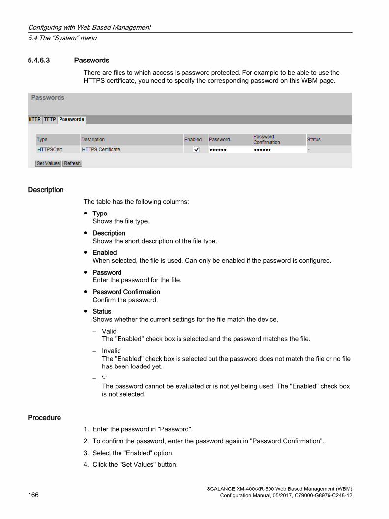
5.4.6.3 PasswordsThere are files to which access is password protected. For example to be able to use the HTTPS certificate, you need to specify the corresponding password on this WBM page.
DescriptionThe table has the following columns:
● TypeShows the file type.
● DescriptionShows the short description of the file type.
● EnabledWhen selected, the file is used. Can only be enabled if the password is configured.
● PasswordEnter the password for the file.
● Password ConfirmationConfirm the password.
● StatusShows whether the current settings for the file match the device.
– ValidThe "Enabled" check box is selected and the password matches the file.
– InvalidThe "Enabled" check box is selected but the password does not match the file or no file has been loaded yet.
– '-'The password cannot be evaluated or is not yet being used. The "Enabled" check box is not selected.
Procedure1. Enter the password in "Password".
2. To confirm the password, enter the password again in "Password Confirmation".
3. Select the "Enabled" option.
4. Click the "Set Values" button.
Configuring with Web Based Management5.4 The "System" menu
SCALANCE XM-400/XR-500 Web Based Management (WBM)166 Configuration Manual, 05/2017, C79000-G8976-C248-12

5.4.7 Events
5.4.7.1 Configuration
Selecting system events On this page, you specify how a device reacts to system events. By enabling the appropriate options, you specify how the device reacts to events. To enable or disable the options, click the relevant check boxes of the columns.
Configuring with Web Based Management5.4 The "System" menu
SCALANCE XM-400/XR-500 Web Based Management (WBM)Configuration Manual, 05/2017, C79000-G8976-C248-12 167

Description of the displayed boxesThe page contains the following boxes:
● "Signaling Contact Method" drop-down listSelect the reaction of the signaling contact from the drop-down list. The following reactions are possible:
– conventionalDefault setting for the signaling contact. An error/fault is displayed by the fault LED and the signaling contact is opened. When the error/fault state no longer exists, the fault LED goes off and the signaling contact is closed.
– User DefinedThe way the signaling contact works does not depend on the error/fault that has occurred. The signaling contact can be opened or closed as required by user actions.
● ""Signaling Contact Status" drop-down listSelect the status of the signaling contact from the drop-down list. The following states are possible:
– ClosedSignaling contact is closed.
– OpenSignaling contact is opened.
The table has the following columns:
● E-MailThe device sends an e-mail. This is only possible if the SMTP server is set up and the "SMTP client" function is enabled.
● TrapThe device sends an SNMP trap. This is only possible if "SNMPv1 Traps" is enabled in "System > Configuration".
● Log tableThe device writes an entry in the event log table, see "Information > Log Table"
● SyslogThe device writes an entry to the system log server. This is only possible if the system log server is set up and the "Syslog client" function is enabled.
Configuring with Web Based Management5.4 The "System" menu
SCALANCE XM-400/XR-500 Web Based Management (WBM)168 Configuration Manual, 05/2017, C79000-G8976-C248-12

● FaultsThe device triggers an error. The error LED lights up
● EventThe column contains the following values:
– Cold/Warm StartThe device was turned on or restarted by the user.
– Link Change This event occurs only when the port status is monitored and has changed, see "System > Fault Monitoring > Link Change".
– Authentication FailureThis event occurs when access is attempted with an incorrect password.
– RMON Alarm An alarm or event has occurred relating to the remote monitoring of the system.
– Power Change This event occurs only when power supply lines 1 and 2 are monitored. It indicates that there was a change to line 1 or line 2. See "System > Fault Monitoring > Power Supply".
– RM State ChangeThe redundancy manager has recognized an interruption or restoration of the ring and has switched the line over or back.
– Spanning Tree ChangeThe STP or RSTP or MSTP topology has changed.
– Fault State Change The fault status has changed. The fault status can relate to the activated port monitoring, the response of the signaling contact or the power supply monitoring.
– Standby State ChangeA device with an established standby connection (master or slave) has activated or deactivated the link to the other ring (standby port). The data traffic was redirected from one Ethernet connection (standby port of the master) to another Ethernet connection (standby port of the slave).
– VRRP State Change (only when routing via VRRP) The status of the virtual router has changed
– Loop DetectionA loop was detected in the network segment.
– Diagnostic AlarmsA diagnostics value has fallen below or exceeded a certain limit.
– OSPF State ChangeThe status of OSPF has changed.
– 802.1X Port Authentication State ChangeThis event occurs with 802.1X authentications.
– PoE State ChangeThe status of PoE has changed.
– FMP Status ChangeThe value of the received power or the power loss has exceeded or fallen below a certain limit.
Configuring with Web Based Management5.4 The "System" menu
SCALANCE XM-400/XR-500 Web Based Management (WBM)Configuration Manual, 05/2017, C79000-G8976-C248-12 169

– Link CheckA disruption was detected on an optical transmission link.
– CLI script fileAn error was detected in the CLI script:
Steps in configuration1. Select the check box in the row of the required event. Select the event in the column under
the following actions:
– Trap
– Log Table
– Syslog
– Faults
2. Click the "Set Values" button.
5.4.7.2 Severity Filters
Setting the Severity FiltersOn this page, set the threshold levels for sending system event notifications.
The first table column shows the client type for which you are making the settings:
● E-mailSending system event messages by e-mail
● Log TableEntry of system events in the log table
● SyslogSending of system event messages to a Syslog server.
Select the required level from the drop-down lists of the second table column.
Configuring with Web Based Management5.4 The "System" menu
SCALANCE XM-400/XR-500 Web Based Management (WBM)170 Configuration Manual, 05/2017, C79000-G8976-C248-12

You can select from the following values:
● CriticalSystem events are processed as of the severity level "Critical".
● WarningSystem events are processed as of the severity level "Warning".
● InfoSystem events are processed as of the severity level "Info".
ProcedureFollow the steps below to configure the required level:
1. Select the required values from the drop-down lists of the second table column after the client types.
2. Click the "Set Values" button.
5.4.8 SMTP client
Network monitoring with e-mailsThe device provides the option of automatically sending an e-mail if an alarm event occurs (for example to the network administrator). The e-mail contains the identification of the sending device, a description of the cause of the alarm in plain language, and a time stamp. This allows centralized network monitoring to be set up for networks with few nodes based on an e-mail system. When an e-mail error message is received, the WBM can be started by the Internet browser using the identification of the sender to read out further diagnostics information.
On this page, you can configure up to three SMTP servers and the corresponding e-mail addresses.
Configuring with Web Based Management5.4 The "System" menu
SCALANCE XM-400/XR-500 Web Based Management (WBM)Configuration Manual, 05/2017, C79000-G8976-C248-12 171

DescriptionThe page contains the following boxes:
● SMTP ClientEnable or disable the SMTP client.
● Sender Email AddressEnter the name of the sender to be included in the e-mail, for example the device name.This setting applies to all configured SMTP servers.
● Send Test MailSend a test e-mail to check your configuration.
● SMTP PortEnter the port via which your SMTP server can be reached.Factory settings: 25This setting applies to all configured SMTP servers.
● SMTP Server AddressEnter the IP address, the FQDN (Fully Qualified Domain Name) or the host name of the SMTP server.
This table contains the following columns:
● SelectSelect the check box in a row to be deleted.
● SMTP Server AddressShows the IP address, the FQDN (Fully Qualified Domain Name) or the host name of the SMTP server.
● Receiver Email AddressEnter the e-mail address to which the device sends an e-mail if a fault occurs.
Procedure1. Enable the "SMTP Client" option.
2. Enter the IP address, the FQDN or the host name of the SMTP server in the "SMTP Server Address" input box.
3. Click the "Create" button. A new entry is generated in the table.
4. In the Receiver Email Address input box. enter the e-mail address to which the device sends an e-mail if a fault occurs.
5. Click the "Set Values" button.
Note
Depending on the properties and configuration of the SMTP server, it may be necessary to adapt the "Sender E-Mail Address” input box for the e-mails. Check with the administrator of the SMTP server.
Configuring with Web Based Management5.4 The "System" menu
SCALANCE XM-400/XR-500 Web Based Management (WBM)172 Configuration Manual, 05/2017, C79000-G8976-C248-12

5.4.9 DHCP
5.4.9.1 DHCP Client
Setting of the DHCP mode If the device is configured as a DHCP client, it starts a DHCP query. As the reply to the query the device receives an IPv4 address from the DHCP server. The server manages an address range from which it assigns IPv4 addresses. It is also possible to configure the server so that the client always receives the same IPv4 address in response to its request.
DescriptionThe page contains the following boxes:
● DHCP client configuration file request (opt 66, 67)Select this option if you want the DHCP client to use options 66 and 67 to download and then enable a configuration file.
● DHCP ModeSelect the DHCP mode from the drop-down list. The following modes are possible:
– via MAC AddressIdentification is based on the MAC address.
– via DHCP Client IDIdentification is based on a freely defined DHCP client ID.
– via System NameIdentification is based on the device name. If the device name is 255 characters long, the last character is not used for identification.
– via PROFINET Name of StationThe identification is made using the PROFINET device name.
Configuring with Web Based Management5.4 The "System" menu
SCALANCE XM-400/XR-500 Web Based Management (WBM)Configuration Manual, 05/2017, C79000-G8976-C248-12 173

The table has the following columns:
● InterfaceInterface to which the setting relates.
● DHCPEnable or disable the DHCP client for the relevant interface.
Procedure 1. Select the required mode from the "DHCP Mode" drop-down list. If you select the DHCP
mode "via DHCP Client ID" an input box appears.
– In the enabled input box "DHCP client ID" enter a string to identify the device. This is then evaluated by the DHCP server.
2. Select the "DHCP Client Configuration Request (Opt. 66, 67) option", if you want the DHCP client to use options 66 and 67 to download and then enable a configuration file.
3. Enable the "DHCP" option in the table.
4. Click the "Set Values" button.
Note
If a configuration file is downloaded, this can trigger a system restart. If the currently running configuration and the configuration in the downloaded configuration file differ, the system is restarted.
Make sure that the option "DHCP Client Configuration Request (Opt. 66, 67"is no longer set.
5.4.9.2 DHCP ServerYou can operate the device as a DHCP server. This allows IP addresses to be assigned automatically to the connected devices. The IP addresses are either distributed dynamically from an address band (pool) you have specified or a specific IP address is assigned to a particular device.
Both with the dynamic and static assignment a pool is selected based on the following criteria:
1. With the DHCP query option 82 is enabled.The DHCP server checks whether there is a pool with option 82. You configure this criterion in the "Relay Agent Information" tab.
2. The DHCP query was received via a relay agent.The DHCP server checks whether the relay agent is located in the subnet of a pool.
3. The port via which the DHCP query was received is enabled in the Port Range.The DHCP server checks whether the IP interface of the port is located in the subnet of a pool. You configure this criterion on the page "Layer 3 (IPv4) > Subnets".
During configuration make sure that the selection of the pool based on the criteria named is possible. If the criteria match several pools, only one pool is selected. The other pools for which the same criteria match are never selected.
Configuring with Web Based Management5.4 The "System" menu
SCALANCE XM-400/XR-500 Web Based Management (WBM)174 Configuration Manual, 05/2017, C79000-G8976-C248-12

On this page, specify the address band from which the connected device receives any IP address. You configure the static assignment of the IP addresses in "Static Leases".
NoteDeleting DHCP server bindings
If you deactivate or delete an IPv4 address band or turn the DHCP server off and on again, the DHCP server assignments are deleted see "Information > DHCP Server".
RequirementThe connected devices are configured so that they obtain the IP address from a DHCP server.
Configuring with Web Based Management5.4 The "System" menu
SCALANCE XM-400/XR-500 Web Based Management (WBM)Configuration Manual, 05/2017, C79000-G8976-C248-12 175

DescriptionThe page contains the following boxes:
● DHCP ServerEnable or disable the DHCP server on the device.
Note
To avoid conflicts with IPv4 addresses, only one device may be configured as a DHCP server in the network.
If you want to operate a DHCP server on the devices of a VRRP group, note the information in the section "Layer 3 (IPv4/IPv6) > VRRP/VRRPv3 > Router".
● Probe address with ICMP echo before offerWhen selected, the DHCP server checks whether or not an IP address has already been assigned. To do this the DHCP server sends ICMP echo messages (ping) to this IPv4 address. If no reply is received, the IPv4 address is assigned.
Note
This check is not made with static assignments.
Note
If there are devices in your network on which the echo service is disabled as default, there may be conflicts with the IPv4 addresses. To avoid this, assign these devices an IPv4 address outside the IPv4 address band used by the DHCP server.
The table has the following columns:
● SelectSelect the check box in the row to be deleted.
● Pool IDShows the number of the IPv4 address band. If you click the "Create" button, a new row with a unique number is created (pool ID).
● InterfaceSelect an IP interface or a router port. The IPv4 addresses are assigned dynamically via this interface.
● EnableSpecify whether or not this IPv4 address band will be used.
Note
If you enable the IPv4 address band, its settings in this and the other DHCP tabs are grayed out and can no longer be edited.
● SubnetEnter the network address range that will be assigned to the devices. Use the CIDR notation.
● Lower IP AddressEnter the IPv4 address that specifies the start of the dynamic IPv4 address band. The IPv4 address must be within the network address range you configured for "Subnet".
Configuring with Web Based Management5.4 The "System" menu
SCALANCE XM-400/XR-500 Web Based Management (WBM)176 Configuration Manual, 05/2017, C79000-G8976-C248-12

● Upper IP addressEnter the IPv4 address that specifies the end of the dynamic IPv4 address band. The IPv4 address must be within the network address range you configured for "Subnet".
● Lease Time (sec)Specify for how many seconds the assigned IPv4 address remains valid. When half the period of validity has elapsed. the DHCP client can extend the period of the assigned IPv4 address. When the entire time has elapsed, the DHCP client needs to request a new IPv4 address.
ProcedureEnable DHCP server globally
1. Select the "DHCP Server"" check box.
2. Click the "Set Values" button.
Configuring a DHCP pool
1. Click the "Create" button.A new row with a unique number (Pool ID) is created.
2. Select an IP interface.
3. Click the "Set Values" button.In the "Port-IP Address Mapping" tab a new row for the pool ID is created. In the "Port" column, all ports can be selected that currently belong to the selected VLAN.In the "Port Range" tab a new row for the pool ID is created. In the row, all ports are enabled that currently belong to the selected VLAN.The standard options for the pool are created in the "DHCP Options" tab.
4. You have the following options for configuring the pool:Configuring a DHCP pool for an IPv4 address band
– Enter the subnet, the lower and the upper IPv4 address.
– Enter the lease time.
– Click the "Set Values" button.
Configuring a DHCP pool for an IPv4 address and assigning it to a certain port
– Change to the "Port-IP Address Mapping" tab.
– Select the required port.In the "Port Range" tab only the selected port is enabled.
– Enter the IPv4 address and the subnet mask.
– Click the "Set Values" button.In the "DHCP Server" tab the boxes "Subnet", "Lower IP Address" and "Upper IP Address" are filled accordingly.
– Configure the lease time in the "DHCP Server" tab.
5. Make the settings you require for the pool in the other DHCP tabs.
Configuring with Web Based Management5.4 The "System" menu
SCALANCE XM-400/XR-500 Web Based Management (WBM)Configuration Manual, 05/2017, C79000-G8976-C248-12 177
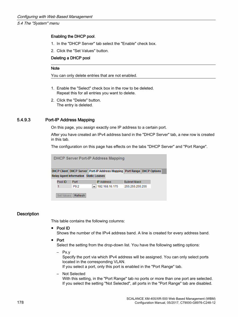
Enabling the DHCP pool.
1. In the "DHCP Server" tab select the "Enable" check box.
2. Click the "Set Values" button.
Deleting a DHCP pool
Note
You can only delete entries that are not enabled.
1. Enable the "Select" check box in the row to be deleted.Repeat this for all entries you want to delete.
2. Click the "Delete" button.The entry is deleted.
5.4.9.3 Port-IP Address MappingOn this page, you assign exactly one IP address to a certain port.
After you have created an IPv4 address band in the "DHCP Server" tab, a new row is created in this tab.
The configuration on this page has effects on the tabs "DHCP Server" and "Port Range".
DescriptionThis table contains the following columns:
● Pool IDShows the number of the IPv4 address band. A line is created for every address band.
● PortSelect the setting from the drop-down list. You have the following setting options:
– Px.ySpecify the port via which IPv4 address will be assigned. You can only select ports located in the corresponding VLAN.If you select a port, only this port is enabled in the "Port Range" tab.
– Not SelectedWith this setting, in the "Port Range" tab no ports or more than one port are selected.If you select the setting "Not Selected", all ports in the "Port Range" tab are disabled.
Configuring with Web Based Management5.4 The "System" menu
SCALANCE XM-400/XR-500 Web Based Management (WBM)178 Configuration Manual, 05/2017, C79000-G8976-C248-12

● IP AddressEnter an IPv4 address.In the "DHCP Server" tab, the boxes "Lower IP Address" and "Upper IP Address" are filled accordingly.
● Subnet MaskEnter a corresponding subnet mask.In the "DHCP Server" tab, the "Subnet" box is filled accordingly.
ProcedureAssign an IP address to the port
1. Select the required port.
2. Enter the IPv4 address and the subnet mask.
3. Click the "Set Values" button.In the "Port Range" tab only the selected port is enabled for the relevant DHCP pool.In the "DHCP Server" tab, the boxes "Subnet", "Lower IP Address" and "Upper IP Address" are filled accordingly for the relevant DHCP pool.
5.4.9.4 Port RangeOn this page, you define the ports via which the IPv4 addresses of an address band are assigned.
After you have created an IPv4 address band in the "DHCP Server" tab, a new line is created in this tab and all ports selected that are currently located in the corresponding VLAN. If you add ports to the VLAN later, the ports are not automatically enabled in this tab.
DescriptionThis table contains the following columns:
● Pool IDShows the number of the IPv4 address band. A line is created for every address band.
● InterfaceShows the assigned IP interface.
Configuring with Web Based Management5.4 The "System" menu
SCALANCE XM-400/XR-500 Web Based Management (WBM)Configuration Manual, 05/2017, C79000-G8976-C248-12 179
● All portsSelect the setting from the drop-down list. You have the following setting options:
– EnabledThe check box is enabled for all ports of the relevant VLAN.
– DisabledThe check box is disabled for all ports of the relevant VLAN.
– No ChangeThe table remains unchanged.
● Px.ySpecify the ports via which IPv4 addresses of the address band will be assigned.You can only select ports located in the corresponding VLAN.
NoteEffects on other tabs
If you enable precisely one port this is selected in the "Port-IP Address Mapping" tab.
If you enable no port or more than one port in the "Port-IP Address Mapping" tab, the setting "Not Selected" is selected.
ProcedureConfiguring individual ports
1. Enable or disable the check box for the required ports.
2. Click the "Set Values" button.
Configuring all ports
1. Select the required entry in the "All ports" drop-down list.
2. Click the "Set Values" button.
5.4.9.5 DHCP OptionsOn this page you specify which DHCP options the DHCP server supports. The various DHCP options are defined in RFC 2132.
The DHCP options 1, 3, 6, 66 and 67 are created automatically when the IPv4 address band is created. With the exception of DHCP option 1, the options can be deleted. With DHCP option 1 the subnet mask is set automatically that you entered for the address band in "DHCP Server". With the DHCP option 3, you can set the internal IPv4 address of the DHCP server as a DHCP parameter using a check box.
Configuring with Web Based Management5.4 The "System" menu
SCALANCE XM-400/XR-500 Web Based Management (WBM)180 Configuration Manual, 05/2017, C79000-G8976-C248-12

DescriptionThe page contains the following boxes:
● Pool IDSelect the required IPv4 address band.
● Option CodeEnter the number of the required DHCP option. The various DHCP options are defined in RFC 2132. The supported DHCP options are listed in the following paragraph.
The table has the following columns:
● SelectSelect the check box in the row to be deleted.
● Pool IDShows the number of the IPv4 address band.
● Option CodeShows the number of the DHCP option.
● DescriptionShows a description of the DHCP option.
Configuring with Web Based Management5.4 The "System" menu
SCALANCE XM-400/XR-500 Web Based Management (WBM)Configuration Manual, 05/2017, C79000-G8976-C248-12 181
● Use Interface IPIf you enable the check box, the IPv4 address is used as the default gateway that is assigned to the IP interface of the address band. If the check box is disabled, you can enter an IPv4 address.
● ValueEnter the DHCP parameter that is transferred to the DHCP client. The content depends on the DHCP option.
– DHCP option 3 (default gateway):Enter the DHCP parameter as an IPv4 address, e.g. 192.168.100.2.
– DHCP option 6 (DNS):Enter the DHCP parameter as an IPv4 address, e.g. 192.168.100.2. You can specify up to three IPv4 addresses separated by commas.
– DHCP option 12 (host name)Enter the host name in the string format.
– DHCP option 66 (TFTP Server):Enter the DHCP parameter as an IPv4 address, e.g. 192.168.100.2.
– DHCP option 67 (boot file name)Enter the name of the boot file in the string format.
DHCP options supportedThe following DHCP options are supported:
● Option 1
● Option 3
● Option 6
● Option 12
● Option 66
● Option 67
ProcedureCreating a DHCP option
1. Select a Pool ID.
2. Enter the option code.
3. Click the "Create" button.
4. Enter a value.
5. If applicable for option 3 enable the "Use Interface IP" check box.
6. Click the "Set Values" button.
Configuring with Web Based Management5.4 The "System" menu
SCALANCE XM-400/XR-500 Web Based Management (WBM)182 Configuration Manual, 05/2017, C79000-G8976-C248-12

Deleting a DHCP option
1. Enable the "Select" check box in the row to be deleted.Repeat this for all entries you want to delete.
2. Click the "Delete" button.The entry is deleted.
5.4.9.6 Relay Agent InformationOn this page you define that devices with a certain remote ID and circuit ID are assigned the IPv4 addresses from a specific address band.
If you create such an entry for an address band, the ports of the address band only react to DHCP queries via a DHCP relay agent (option 82). You can create further address bands for the same IP interfaces so that ports react to different requests.
DescriptionThe page contains the following boxes:
● Pool IDSelect the required IPv4 address band.
● Remote IDEnter the remote ID.
● Circuit IDEnter the circuit ID.
The table has the following columns:
● SelectSelect the check box in the row to be deleted.
● Pool IDShows the number of the IPv4 address band.
Configuring with Web Based Management5.4 The "System" menu
SCALANCE XM-400/XR-500 Web Based Management (WBM)Configuration Manual, 05/2017, C79000-G8976-C248-12 183

● Remote IDShows the remote ID.
● Circuit IDShows the circuit ID.
ProcedureCreating an entry
1. Select a Pool ID.
2. Enter the remote ID.
3. Enter the circuit ID.
4. Click the "Create" button.
Deleting an entry
1. Enable the "Select" check box in the row to be deleted.Repeat this for all entries you want to delete.
2. Click the "Delete" button.The entry is deleted.
5.4.9.7 Static LeasesOn this page you define that DHCP clients are assigned a preset IPv4 address depending on their client ID or MAC address.
Configuring with Web Based Management5.4 The "System" menu
SCALANCE XM-400/XR-500 Web Based Management (WBM)184 Configuration Manual, 05/2017, C79000-G8976-C248-12

DescriptionThe page contains the following boxes:
● Pool IDSelect the required IPv4 address band.
● Client identification methodSelect the method according to which a client is identified.
– Ethernet MACThe client is identified by its MAC address.
– Client IDThe client is identified by a freely defined DHCP client ID.
● ValueEnter the MAC address (Ethernet MAC) or the client ID of the client.
The table has the following columns:
● SelectSelect the check box in the row to be deleted.
● Pool IDShows the number of the IPv4 address band.
● Identification methodShows whether the client is identified by its MAC address or the client ID.
● ValueShows the MAC address or client ID of the client.
● IP AddressSpecify the IPv4 address that will be assigned to the client. The IPv4 address must be within the IPv4 address band.
ProcedureCreating static leases
1. Select a Pool ID.
2. Select the Client identification method.
3. Enter the value.
4. Click the "Create" button.
5. Specify the IPv4 address that will be assigned to the client.
6. Click the "Set Values" button.
Deleting static leases
1. Enable the "Select" check box in the row to be deleted.Repeat this for all entries you want to delete.
2. Click the "Delete" button.The entry is deleted.
Configuring with Web Based Management5.4 The "System" menu
SCALANCE XM-400/XR-500 Web Based Management (WBM)Configuration Manual, 05/2017, C79000-G8976-C248-12 185

5.4.10 SNMP
5.4.10.1 General
Configuration of SNMPOn this page, you make the basic settings for SNMP. Enable the check boxes according to the function you want to use.
Configuring with Web Based Management5.4 The "System" menu
SCALANCE XM-400/XR-500 Web Based Management (WBM)186 Configuration Manual, 05/2017, C79000-G8976-C248-12

DescriptionThe page contains the following boxes:
● SNMP Select the SNMP protocol from the drop-down list. The following settings are possible:
– "-" (disabled)SNMP is disabled.
– SNMPv1/v2c/v3SNMPv1/v2c/v3 is supported.
Note
Note that SNMP in versions 1 and 2c does not have any security mechanisms.
– SNMPv3Only SNMPv3 is supported.
● SNMPv1/v2c Read-OnlyIf you enable this option, SNMPv1/v2c can only read the SNMP variables.
NoteCommunity String
For security reasons, do not use the standard values "public" or "private". Change the community strings following the initial installation.
The recommended minimum length for community strings is 6 characters.
● SNMPv1/v2c Read Community StringEnter the community string for read access of the SNMP protocol.
● SNMPv1/v2c Read/Write Community StringEnter the community string for read and write access of the SNMP protocol.
● SNMPv1 TrapsEnable or disable the sending of SNMPv1 traps (alarm frames). On the "Trap" tab, specify the IP addresses of the devices to which SNMPv1 traps will be sent.
● SNMPv1/v2c Trap Community StringEnter the community string for sending SNMPv1/v2c messages.
Configuring with Web Based Management5.4 The "System" menu
SCALANCE XM-400/XR-500 Web Based Management (WBM)Configuration Manual, 05/2017, C79000-G8976-C248-12 187

● SNMPv3 User Migration
– EnabledIf the function is enabled, an SNMP engine ID is generated that can be migrated. You can transfer configured SNMPv3 users to a different device.If you enable this function and load the configuration of the device on another device, configured SNMPv3 users are retained.
– DisabledIf the function is disabled, a device-specific SNMP engine ID is generated. To generate the ID, the agent MAC address of the device is used. You cannot transfer this SNMP user configuration to other devices.If you load the configuration of the device on another device, all configured SNMPv3 users are deleted.
● SNMP Engine IDShows the SNMP engine ID.
Procedure1. Select the required option from the "SNMP" drop-down list:
– "-" (disabled)
– SNMPv1/v2c/v3
– SNMPv3
2. Enable the "SNMPv1/v2c Read Only" check box if you only want read access to SNMP variables with SNMPv1/v2c.
3. Enter the required character string in the "SNMPv1/v2c Read Community String" input box.
4. Enter the required character string in the "SNMPv1/v2c Read/Write Community String" input box.
5. If necessary, enable the SNMPv3 User Migration.
6. Click the "Set Values" button.
See alsoSNMP (Page 35)
Configuring with Web Based Management5.4 The "System" menu
SCALANCE XM-400/XR-500 Web Based Management (WBM)188 Configuration Manual, 05/2017, C79000-G8976-C248-12
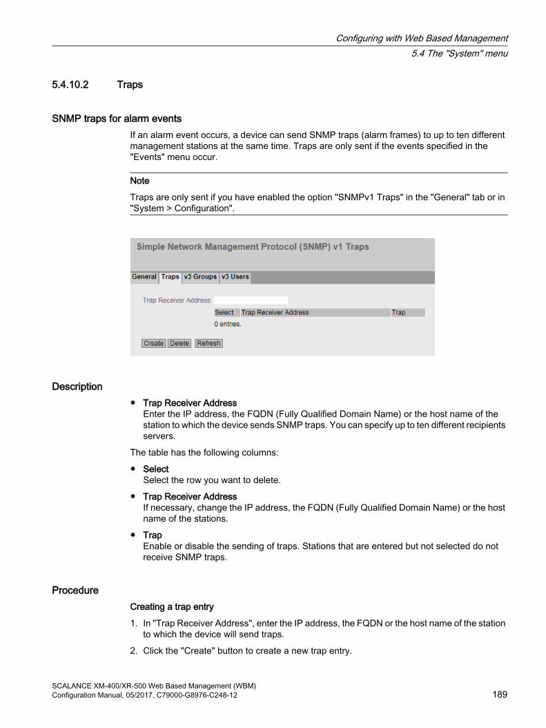
5.4.10.2 Traps
SNMP traps for alarm events If an alarm event occurs, a device can send SNMP traps (alarm frames) to up to ten different management stations at the same time. Traps are only sent if the events specified in the "Events" menu occur.
Note
Traps are only sent if you have enabled the option "SNMPv1 Traps" in the "General" tab or in "System > Configuration".
Description● Trap Receiver Address
Enter the IP address, the FQDN (Fully Qualified Domain Name) or the host name of the station to which the device sends SNMP traps. You can specify up to ten different recipients servers.
The table has the following columns:
● SelectSelect the row you want to delete.
● Trap Receiver AddressIf necessary, change the IP address, the FQDN (Fully Qualified Domain Name) or the host name of the stations.
● TrapEnable or disable the sending of traps. Stations that are entered but not selected do not receive SNMP traps.
ProcedureCreating a trap entry
1. In "Trap Receiver Address", enter the IP address, the FQDN or the host name of the station to which the device will send traps.
2. Click the "Create" button to create a new trap entry.
Configuring with Web Based Management5.4 The "System" menu
SCALANCE XM-400/XR-500 Web Based Management (WBM)Configuration Manual, 05/2017, C79000-G8976-C248-12 189

3. Select the check box in the required row "Trap".
4. Click the "Set Values" button.
Deleting a trap entry
1. Enable "Select" in the row to be deleted.
2. Click the "Delete" button. The entry is deleted.
5.4.10.3 v3 Groups
Security settings and assigning permissionsSNMP version 3 allows permissions to be assigned, authentication, and encryption at protocol level. The security level and read/write permissions are assigned according to groups. The settings automatically apply to every member of a group.
DescriptionThe page contains the following boxes:
● Group NameEnter the name of the group. The maximum length is 32 characters.
● Security LevelSelect the security level (authentication, encryption) valid for the selected group. The available options are as follows:
– no Auth/no PrivNo authentication enabled / no encryption enabled.
– Auth/no PrivAuthentication enabled / no encryption enabled.
– Auth/PrivAuthentication enabled / encryption enabled.
Configuring with Web Based Management5.4 The "System" menu
SCALANCE XM-400/XR-500 Web Based Management (WBM)190 Configuration Manual, 05/2017, C79000-G8976-C248-12

The table has the following columns:
● SelectSelect the row you want to delete.
● Group NameShows the defined group names.
● Security LevelShows the configured security level.
● ReadEnable or disable read access for the required group.
● WriteEnable or disable write access for the required group.
Note
For write access to work, you also need to enable read access.
● PersistenceShows whether or not the group is assigned to an SNMPv3 user. If the group is not assigned to an SNMPv3 user, no automatic saving is triggered and the configured group is deleted after restarting the device.
– YesThe group is assigned to an SNMPv3 user.
– NoThe group is not assigned to an SNMPv3 user.
ProcedureCreating a new group
1. Enter the required group name in "Group Name".
2. Select the required security level from the "Security Level" drop-down list.
3. Click the "Create" button to create a new entry.
4. Specify the required read rights for the group in "Read".
5. Specify the required write rights for the group in "Write".
6. Click the "Set Values" button.
Modifying a group
1. Specify the required read rights for the group in "Read".
2. Specify the required write rights for the group in "Write".
3. Click the "Set Values" button.
Note
Once a group name and the security level have been specified, they can no longer be modified after the group is created. If you want to change the group name or the security level, you will need to delete the group and recreate it and reconfigure it with the new name.
Configuring with Web Based Management5.4 The "System" menu
SCALANCE XM-400/XR-500 Web Based Management (WBM)Configuration Manual, 05/2017, C79000-G8976-C248-12 191

Deleting a group
1. Enable "Select" in the row to be deleted.Repeat this for all groups you want to delete.
2. Click the "Delete" button. The entries are deleted.
5.4.10.4 v3 Users
User-specific security settings On the WBM page, you can create new SNMPv3 users and modify or delete existing users. The user-based security model works with the concept of the user name; in other words, a user ID is added to every frame. This user name and the applicable security settings are checked by both the sender and recipient.
Configuring with Web Based Management5.4 The "System" menu
SCALANCE XM-400/XR-500 Web Based Management (WBM)192 Configuration Manual, 05/2017, C79000-G8976-C248-12

DescriptionThe page contains the following boxes:
● User NameEnter a freely selectable user name. After you have entered the data, you can no longer modify the name.
The table has the following columns:
● SelectSelect the row you want to delete.
● User NameShows the created users.
● Group NameSelect the group which will be assigned to the user.
● Authentication ProtocolSpecify the authentication protocol for which a password will be stored.The following settings are available:
– None
– MD5
– SHA
● Encryption ProtocolSpecify whether or not a password should be stored for encryption with the DES algorithm. Can only be enabled when an authentication protocol has been selected.
● Authentication PasswordEnter the authentication password in the first input box. This password must have at least 1 character, the maximum length is 32 characters.
NoteLength of the password
As an important measure to maximize security, we recommend that the password has a minimum length of 6 characters and that it contains special characters, uppercase/lowercase letters, numbers.
● Authentication Password ConfirmationConfirm the password by repeating the entry.
● Privacy PasswordEnter your encryption password. This password must have at least 1 character, the maximum length is 32 characters.
NoteLength of the password
As an important measure to maximize security, we recommend that the password has a minimum length of 6 characters and that it contains special characters, uppercase/lowercase letters, numbers.
Configuring with Web Based Management5.4 The "System" menu
SCALANCE XM-400/XR-500 Web Based Management (WBM)Configuration Manual, 05/2017, C79000-G8976-C248-12 193

● Privacy Password ConfirmationConfirm the encryption password by repeating the entry.
● PersistenceShows whether or not the user is assigned to an SNMPv3 group. If the user is not assigned to an SNMPv3 group, no automatic saving is triggered and the configured user is deleted after restarting the device.
– YesThe user is assigned to an SNMPv3 group.
– NoThe user is not assigned to an SNMPv3 group.
ProcedureCreate a new user
1. Enter the name of the new user in the "User Name" input box.
2. Click the "Create" button. A new entry is generated in the table.
3. In "Group Name", select the group to which the new user will belong.If the group has not yet been created, change to the "v3 Groups" page and make the settings for this group.
4. If an authentication is necessary for the selected group, select the authentication algorithm in "Authentication Protocol".In the relevant input boxes, enter the authentication password and its confirmation.
5. If encryption was specified for the group, select the algorithm in "Privacy Protocol". In the relevant input boxes, enter the encryption password and the confirmation.
6. Click the "Set Values" button.
Delete user
1. Enable "Select" in the row to be deleted.Repeat this for all users you want to delete.
2. Click the "Delete" button. The entry is deleted.
5.4.11 System Time
There are different methods that can be used to set the system time of the device. Only one method can be active at any one time.
If one method is activated, the previously activated method is automatically deactivated.
Configuring with Web Based Management5.4 The "System" menu
SCALANCE XM-400/XR-500 Web Based Management (WBM)194 Configuration Manual, 05/2017, C79000-G8976-C248-12

5.4.11.1 Manual Setting
Manual setting of the system time On this page, you set the date and time of the system yourself. For this setting to be used, enable "Time Manually".
DescriptionThe page contains the following boxes:
● Time ManuallyEnable or disable the manual time setting. If you enable the option, the "System Time" input box can be edited.
● System TimeEnter the date and time in the format "MM/DD/YYYY HH:MM:SS".
● Use PC TimeClick the button to use the time setting of the PC.
● Last Synchronization TimeShows when the last time-of-day synchronization took place. If no time-of-day synchronization was possible, the box displays "Date/time not set".
Configuring with Web Based Management5.4 The "System" menu
SCALANCE XM-400/XR-500 Web Based Management (WBM)Configuration Manual, 05/2017, C79000-G8976-C248-12 195

● Last Synchronization MechanismShows how the last time synchronization was performed.
– Not setThe time was not set.
– ManualManual time setting
– SNTPAutomatic time-of-day synchronization with SNTP
– NTPAutomatic time-of-day synchronization with NTP
– SIMATICAutomatic time-of-day synchronization using the SIMATIC time frame
– PTPAutomatic time-of-day synchronization with PTP
● Daylight Saving Time (DST)Shows whether the daylight saving time changeover is active.
– active (offset +1 h)The system time was changed to daylight saving time; in other words an hour was added. You can see the current system time at the top right in the selection area of the WBM.The set time continues to be displayed in the "System Time" box.
– inactive (offset +0 h)The current system time is not changed.
Procedure1. Enable the "Time Manually" option.
2. Click in the "System Time" input box.
3. In the "System Time" input box, enter the date and time in the format "MM/DD/YYYY HH:MM:SS".
4. Click the "Set Values" button.The date and time are adopted and "Manual" is entered in "Last Synchronization Mechanism" box.
Configuring with Web Based Management5.4 The "System" menu
SCALANCE XM-400/XR-500 Web Based Management (WBM)196 Configuration Manual, 05/2017, C79000-G8976-C248-12

5.4.11.2 DST Overview
Daylight saving time switchoverOn this page, you can create new entries for the daylight saving time changeover. The table provides an overview of the existing entries.
SettingsThe page contains the following boxes:
● SelectSelect the row you want to delete.
● DST No.Shows the number of the entry.If you create a new entry, a new line with a unique number is created.
● NameShows the name of the entry.
● YearShows the year for which the entry was created.
● Start DateShows the month, day and time for the start of daylight saving time.
● End DateShows the month, day and time for the end of daylight saving time.
● Recurring DateWith an entry of the type "Recurring", the period in which daylight saving time is active is displayed consisting of week, day, month and time of day.With an entry of the type "Date" a "-" is displayed.
Configuring with Web Based Management5.4 The "System" menu
SCALANCE XM-400/XR-500 Web Based Management (WBM)Configuration Manual, 05/2017, C79000-G8976-C248-12 197
● StatusShows the status of the entry:
– EnabledThe entry was created correctly.
– InvalidThe entry was created new and the start and end date are identical.
● TypeShows how the daylight saving time changeover is made:
– DateA fixed date is entered for the daylight saving time changeover.
– RecurringA rule was defined for the daylight saving time changeover.
ProcedureCreating an entry
1. Click the "Create" button.A new entry is created in the table.
2. Click on the required entry in the "DST No column.You change to the "DST Configuration" page.
3. Select the required type in the "Type" drop-down list.Depending on the selected type, various settings are available.
4. Enter a name name in the "Name" box.
5. If you have selected the type "Date", fill in the following boxes.
– Year
– Day (for start and end date)
– Hour (for start and end date)
– Month (for start and end date)
6. If you have selected the type "Recurring", fill in the following boxes.
– Hour (for start and end date)
– Month (for start and end date)
– Week (for start and end date)
– Day (for start and end date)
7. Click the "Set Values" button.
Deleting an entry
1. Enable "Select" in the row to be deleted.
2. Click the "Delete" button. The entry is deleted.
Configuring with Web Based Management5.4 The "System" menu
SCALANCE XM-400/XR-500 Web Based Management (WBM)198 Configuration Manual, 05/2017, C79000-G8976-C248-12

5.4.11.3 DST Configuration
Configuring the daylight saving time switchoverOn this page, you can configure the entries for the daylight saving time changeover. As result of the changeover to daylight saving or standard time, the system time for the local time zone is correctly set.
You can define a rule for the daylight saving time changeover or specify a fixed date.
Settings
Note
The content of this page depends on the selection in the "Type" box.
The boxes "DST No.", "Type" and "Name" are always shown.
● DST No.Select the type of the entry.
● TypeSelect how the daylight saving time changeover is made:
– DateYou can set a fixed date for the daylight saving time changeover.This setting is suitable for regions in which the daylight saving time changeover is not governed by rules.
– RecurringYou can define a rule for the daylight saving time changeover.This setting is suitable for regions in which the daylight saving time always begins or ends on a certain weekday.
● NameEnter a name for the entry.The name can be a maximum of 16 characters long.
Settings with "Date" selected
Configuring with Web Based Management5.4 The "System" menu
SCALANCE XM-400/XR-500 Web Based Management (WBM)Configuration Manual, 05/2017, C79000-G8976-C248-12 199

You can set a fixed date for the start and end of daylight saving time.
● YearEnter the year for the daylight saving time changeover.
● Start DateEnter the following values for the start of daylight saving time:
– DaySpecify the day.
– HourSpecify the hour.
– MonthSpecify the month.
● End DateEnter the following values for the end of daylight saving time:
– DaySpecify the day.
– HourSpecify the hour.
– MonthSpecify the month.
Settings with "Recurring" selected
Configuring with Web Based Management5.4 The "System" menu
SCALANCE XM-400/XR-500 Web Based Management (WBM)200 Configuration Manual, 05/2017, C79000-G8976-C248-12

You can create a rule for the daylight saving time changeover.
● YearEnter the year for the daylight saving time changeover.
● Start DateEnter the following values for the start of daylight saving time:
– HourSpecify the hour.
– MonthSpecify the month.
– WeekSpecify the week.You can select the first to fourth or the last week of the month.
– DaySpecify the weekday.
● End DateEnter the following values for the end of daylight saving time:
– HourSpecify the hour.
– MonthSpecify the month.
– WeekSpecify the week.You can select the first to fourth or the last week of the month.
– DaySpecify the weekday.
Configuring with Web Based Management5.4 The "System" menu
SCALANCE XM-400/XR-500 Web Based Management (WBM)Configuration Manual, 05/2017, C79000-G8976-C248-12 201

5.4.11.4 SNTP Client
Time-of-day synchronization in the networkSNTP (Simple Network Time Protocol) is used for synchronizing the time in the network. The time frames are sent by an SNTP server in the network.
DescriptionThe page contains the following boxes:
● SNTP ClientEnable or disable automatic time-of-day synchronization using SNTP.
● Current System TimeShows the current date and current normal time received by the IE switch. If you specify a time zone, the time information is adapted accordingly.
● Last Synchronization TimeShows when the last time-of-day synchronization took place.
Configuring with Web Based Management5.4 The "System" menu
SCALANCE XM-400/XR-500 Web Based Management (WBM)202 Configuration Manual, 05/2017, C79000-G8976-C248-12
● Last Synchronization MechanismShows how the last time synchronization was performed. The following methods are possible:
– Not setThe time was not set.
– ManualManual time setting
– SNTPAutomatic time-of-day synchronization with SNTP
– NTPAutomatic time-of-day synchronization with NTP
– SIMATICAutomatic time-of-day synchronization using the SIMATIC time frame
– PTPAutomatic time-of-day synchronization with PTP
● Time ZoneIn this box, enter the time zone you are using in the format "+/- HH:MM". The time zone relates to UTC standard world time.The time in the "Current System Time" box is adapted accordingly.
● Daylight Saving Time (DST)Shows whether the daylight saving time changeover is active.
– active (offset +1 h)The system time was changed to daylight saving time; in other words an hour was added. You can see the current system time at the top right in the selection area of the WBM.The normal time including the time zone continues to be displayed in the "Current System Time" box.
– inactive (offset +0 h)The current system time is not changed.
● SNTP ModeSelect the synchronization mode from the drop-down list. The following types of synchronization are possible:
– ListenWith this mode, the device is passive and receives SNTP frames that deliver the time of day. Settings in the input boxes "SNTP Server Address" and "SNTP Server Port" have no effect in this mode.In this mode, only IPv4 addresses are supported.
– PollIf you select this mode, the input box "Poll Interval[s]" is displayed to allow further configuration. In this mode the settings in the input boxes "SNTP Server Address" and "SNTP Server Port" are taken into account. With this type of synchronization, the device is active and sends a time query to the SNTP server.In this mode, IPv4 and IPv6 addresses are supported.
● Poll Interval[s]Here, enter the interval between two-time queries. In this box, you enter the query interval in seconds. Possible values are 16 to 16284 seconds.
Configuring with Web Based Management5.4 The "System" menu
SCALANCE XM-400/XR-500 Web Based Management (WBM)Configuration Manual, 05/2017, C79000-G8976-C248-12 203

● SNTP Server AddressEnter the IP address or the FQDN (Fully Qualified Domain Name) of the SNTP server.
● SNTP Server Port Enter the port of the SNTP server. The following ports are possible:
– 123 (standard port)
– 1025 to 36564
● PrimaryThe check mark is set for the SNTP server that you create first. If several SNTP servers have been created, the primary server is queried first.
Procedure1. Click the "SNTP Client" check box to enable the automatic time setting.
2. In the "Time Zone" input box, enter the local time difference to world time (UTC). The input format is "+/-HH:MM" (for example +02:00 for CEST), because the SNTP server always sends the UTC time. This time is then recalculated and displayed as the local time based on the specified time zone. You configure the daylight saving time switchover on the pages "System > System Time > DST Overview" and "System > System Time > DST Configuration". You also need to take this into account when completing the "Time Zone" input box.
3. Select one of the following options from the "SNTP Mode" drop-down list:
– PollFor this mode, you need to configure the following:- time zone difference (step 2)- query interval (step 4) -time server (step 5) - Port (step 7)- complete the configuration with step 8.
– ListenFor this mode, you need to configure the following:- time difference to the time sent by the server (step 2)- time server (step 5) - port (step 7) - complete the configuration with step 8.
4. In the "Poll Interval[s]" input box, enter the time in seconds after which a new time query is sent to the time server.
5. In the "SNTP Server Address" input box, enter the IP address or the FQDN of the SNTP server whose frames will be used to synchronize the time of day.
6. Click the "Create" button.A new row is inserted in the table for the SNTP server.
7. In the "SNTP Server Port" column, enter the port via which the SNTP server is available. The port can only be modified if the IPv4 address or the FQDN name of the SNTP server is entered.
8. Click the "Set Values" button to transfer your changes to the device.
Configuring with Web Based Management5.4 The "System" menu
SCALANCE XM-400/XR-500 Web Based Management (WBM)204 Configuration Manual, 05/2017, C79000-G8976-C248-12

5.4.11.5 NTP Client
Automatic time-of-day setting with NTP If you require time-of-day synchronization using NTP, you can make the relevant settings here.
DescriptionThe page contains the following boxes:
● NTP ClientSelect this check box to enable automatic time-of-day synchronization with NTP.
● Current System TimeShows the current date and current normal time received by the IE switch. If you specify a time zone, the time information is adapted accordingly.
● Last Synchronization TimeShows when the last time-of-day synchronization took place.
Configuring with Web Based Management5.4 The "System" menu
SCALANCE XM-400/XR-500 Web Based Management (WBM)Configuration Manual, 05/2017, C79000-G8976-C248-12 205

● Last Synchronization MechanismShows how the last time synchronization was performed. The following methods are possible:
– Not setThe time was not set.
– ManualManual time setting
– SNTPAutomatic time-of-day synchronization with SNTP
– NTPAutomatic time-of-day synchronization with NTP
– SIMATICAutomatic time-of-day synchronization using the SIMATIC time frame
– PTPAutomatic time-of-day synchronization with PTP
● Time ZoneIn this box, enter the time zone you are using in the format "+/- HH:MM". The time zone relates to UTC standard world time.The time in the "Current System Time" box is adapted accordingly.
● Daylight Saving Time (DST)Shows whether the daylight saving time changeover is active.
– active (offset +1 h)The system time was changed to daylight saving time; in other words an hour was added. You can see the current system time at the top right in the selection area of the WBM.The normal time including the time zone continues to be displayed in the "Current System Time" box.
– inactive (offset +0 h)The current system time is not changed.
● NTP Server IndexSelect the index of the NTP server. The server with the lowest index is queried first.
● NTP Server AddressEnter the IP address, the FQDN (Fully Qualified Domain Name) or the host name of the NTP server.
● NTP Server PortEnter the port of the NTP server.The following ports are possible:
– 123 (standard port)
– 1025 to 36564
● Poll Interval[s]Here, enter the interval between two-time queries. In this box, you enter the query interval in seconds. Possible values are 64 to 1024 seconds.
Configuring with Web Based Management5.4 The "System" menu
SCALANCE XM-400/XR-500 Web Based Management (WBM)206 Configuration Manual, 05/2017, C79000-G8976-C248-12

Procedure 1. Click the "NTP Client" check box to enable the automatic time setting using NTP.
2. In the "Time Zone" input box, enter the local time difference to world time (UTC). The input format is "+/-HH:MM" (for example +02:00 for CEST, the Central European Summer Time), because the NTP server always sends the UTC time. This time is then recalculated as the local time based on the specified time zone. You configure the daylight saving time switchover on the pages "System > System Time > DST Overview" and "System > System Time > DST Configuration". You also need to take this into account when completing the "Time Zone" input box.
3. Select the "NTP Server Index".
4. Click the "Create" button.A new row is inserted in the table for the NTP server.
5. In the "NTP Server Address" input box, enter the IP address, the FQDN or the host name of the NTP server whose frames will be used to synchronize the time of day.
6. In the "NTP Server Port" column, enter the port via which the NTP server is available. The port can only be modified if the IPv4 address or the FQDN name of the NTP server is entered.
7. In the "Poll Interval" column, enter the time in seconds after which a new time query is sent to the time server.
8. Click the "Set Values" button.
5.4.11.6 SIMATIC time client
Time setting via SIMATIC time client
DescriptionThe page contains the following boxes:
● SIMATIC Time ClientSelect this check box to enable the device as a SIMATIC time client.
● Current System TimeShows the current system time.
Configuring with Web Based Management5.4 The "System" menu
SCALANCE XM-400/XR-500 Web Based Management (WBM)Configuration Manual, 05/2017, C79000-G8976-C248-12 207

● Last Synchronization TimeShows when the last time-of-day synchronization took place.
● Last Synchronization MechanismShows how the last time synchronization was performed. The following methods are possible:
– Not setThe time was not set.
– ManualManual time setting
– SNTPAutomatic time-of-day synchronization with SNTP
– NTPAutomatic time-of-day synchronization with NTP
– SIMATICAutomatic time-of-day synchronization using the SIMATIC time frame
– PTPAutomatic time-of-day synchronization with PTP
Procedure1. Click the "SIMATIC Time Client" check box to enable the SIMATIC Time Client.
2. Click the "Set Values" button.
5.4.11.7 PTP ClientThe following devices support time-of-day synchronization using PTP:
● SCALANCE XR528-6M
● SCALANCE XR552-12M
Automatic time-of-day setting with PTPIf you require time-of-day synchronization using PTP, you can make the relevant settings here.
Configuring with Web Based Management5.4 The "System" menu
SCALANCE XM-400/XR-500 Web Based Management (WBM)208 Configuration Manual, 05/2017, C79000-G8976-C248-12

DescriptionThe page contains the following boxes:
● PTP ClientSelect this check box to enable automatic time-of-day synchronization with PTP.
● Current System TimeShows the current date and current normal time obtained due to time synchronization in the network. If you specify a time zone, the time information is adapted accordingly.
● Last Synchronization TimeShows when the last time-of-day synchronization took place.
● Last Synchronization MechanismShows how the last time synchronization was performed. The following methods are possible:
– Not setThe time was not set.
– ManualManual time setting
– SNTPAutomatic time-of-day synchronization with SNTP
– NTPAutomatic time-of-day synchronization with NTP
– SIMATICAutomatic time-of-day synchronization using the SIMATIC time frame
– PTPAutomatic time-of-day synchronization with PTP
● Time ZoneIn this box, enter the time zone you are using in the format "+/- HH:MM". The time zone relates to UTC standard world time.The time in the "Current System Time" box is adapted accordingly.
● Daylight Saving Time (DST)Shows whether the daylight saving time changeover is active.
– active (offset +1 h)The system time was changed to daylight saving time; in other words an hour was added. You can see the current system time at the top right in the selection area of the WBM.The normal time including the time zone continues to be displayed in the "Current System Time" box.
– inactive (offset +0 h)The current system time is not changed.
Procedure 1. Click the "PTP Client" check box to enable the automatic time setting using PTP.
2. Specify the a time zone, if applicable.
3. Click the "Set Values" button.
Configuring with Web Based Management5.4 The "System" menu
SCALANCE XM-400/XR-500 Web Based Management (WBM)Configuration Manual, 05/2017, C79000-G8976-C248-12 209

5.4.12 Automatic logout
Setting the automatic logout On this page, set the time intervals after which there is an automatic logout from the WBM or CLI following user inactivity.
If you have been logged out automatically, you will need to log in again.
Configuration1. Enter a value of 60-3600 seconds in the "Web Based Management [s]" input box. If you
enter the value 0, the automatic logout is disabled.
2. Enter a value of 60-600 seconds in the "CLI (TELNET, SSH, Serial) [s]" input box. If you enter the value 0, the automatic logout is disabled.
3. Click the "Set Values" button.
5.4.13 Configuration of the SELECT/SET button
Description of the SELECT/SET buttonThe "SELECT/SET" button is used for the following:
● Changing the display mode,
● Resetting to factory defaults,
● Defining the fault mask and the LED display.
You will find a detailed description of the individual functions available with the buttons in the device operating instructions.
On this page, the functionality of the SELECT/SET button can be restricted or fully disabled.
Configuring with Web Based Management5.4 The "System" menu
SCALANCE XM-400/XR-500 Web Based Management (WBM)210 Configuration Manual, 05/2017, C79000-G8976-C248-12

Description of the displayed boxesThe following functions are possible:
● Restore Factory DefaultsEnable or disable the "Restore Factory Defaults" function with the Select/set button.
CAUTION
Button function "Restore Factory Defaults" active during startup
If you have disabled this function in your configuration, disabling is only valid during operation. When restarting, for example after power down, the function is active until the configuration is loaded so that the device can inadvertently be reset to the factory settings. This may cause unwanted disruption in network operation since the device needs to be reconfigured if this occurs. An inserted PLUG is also deleted and returned to the status as shipped.
CAUTION
Resetting with WBM and CLI
if you have disabled the "Restore Factory Defaults" in your configuration, the disabling does not apply to the CLI command "Restart" and for the WBM page "System > Restart". This means that the device can inadvertently be reset to the factory defaults. This may cause unwanted disruption in network operation since the device then needs to be reconfigured. An inserted PLUG is also deleted and returned to the status as shipped.
● Redundancy ManagerEnables/disables the redundancy manager function.
● Set Fault MaskEnable or disable the function "Define fault mask via the LED display" with the SELECT/SET button.
Steps in configuration1. To use the required functionality, select the corresponding check box.
2. Click the "Set Values" button.
Configuring with Web Based Management5.4 The "System" menu
SCALANCE XM-400/XR-500 Web Based Management (WBM)Configuration Manual, 05/2017, C79000-G8976-C248-12 211
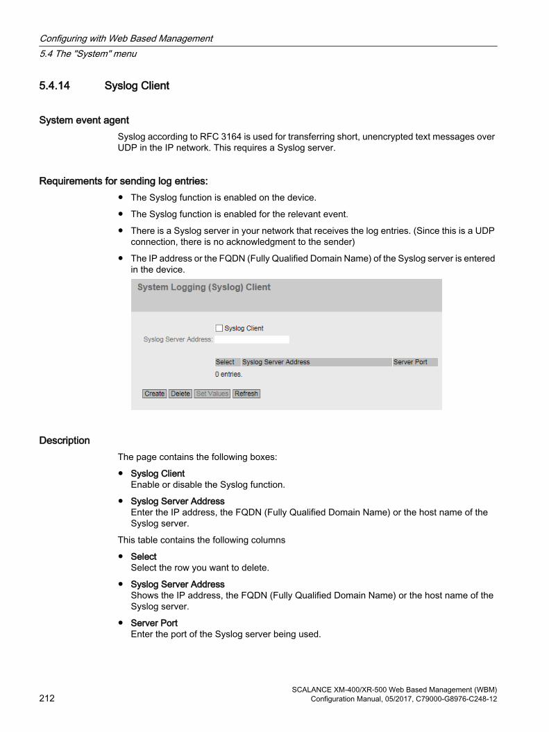
5.4.14 Syslog Client
System event agent Syslog according to RFC 3164 is used for transferring short, unencrypted text messages over UDP in the IP network. This requires a Syslog server.
Requirements for sending log entries:● The Syslog function is enabled on the device.
● The Syslog function is enabled for the relevant event.
● There is a Syslog server in your network that receives the log entries. (Since this is a UDP connection, there is no acknowledgment to the sender)
● The IP address or the FQDN (Fully Qualified Domain Name) of the Syslog server is entered in the device.
DescriptionThe page contains the following boxes:
● Syslog ClientEnable or disable the Syslog function.
● Syslog Server AddressEnter the IP address, the FQDN (Fully Qualified Domain Name) or the host name of the Syslog server.
This table contains the following columns
● SelectSelect the row you want to delete.
● Syslog Server AddressShows the IP address, the FQDN (Fully Qualified Domain Name) or the host name of the Syslog server.
● Server PortEnter the port of the Syslog server being used.
Configuring with Web Based Management5.4 The "System" menu
SCALANCE XM-400/XR-500 Web Based Management (WBM)212 Configuration Manual, 05/2017, C79000-G8976-C248-12

ProcedureEnabling function
1. Select the "Syslog Client" check box.
2. Click the "Set Values" button.
Creating a new entry
1. In the "Syslog Server Address" input box, enter the IP address, the FQDN or the host name of the Syslog server on which the log entries will be saved.
2. Click the "Create" button. A new row is inserted in the table.
3. In the "Server Port" input box, enter the number of the UDP port of the server.
4. Click the "Set Values" button.
Note
The default setting of the server port is 514.
Changing the entry
1. Delete the entry.
2. Create a new entry.
Deleting an entry
1. Select the check box in the row to be deleted.
2. Click the "Delete" button. All selected entries are deleted and the display is refreshed.
Configuring with Web Based Management5.4 The "System" menu
SCALANCE XM-400/XR-500 Web Based Management (WBM)Configuration Manual, 05/2017, C79000-G8976-C248-12 213

5.4.15 Ports
5.4.15.1 Overview
Overview of the port configurationThe page shows the configuration for the data transfer for all ports of the device. You cannot configure anything on this page.
Description of the displayed boxesThe table has the following columns:
● PortShows the configurable ports. The entry is a link. If you click on the link, the corresponding configuration page is opened. The port is made up of the module number and the port number, for example port 0.1 is module 0, port 1.
● Port nameShows the name of the port.
● Port Type (only with routing)Shows the type of the port. The following types are possible:
– Router port
– Switch Port VLAN Hybrid
– Switch-Port VLAN Trunk
– Switch Port VLAN Host
– Switch-Port PVLAN Promiscuous
– Switch Port VLAN Access
Configuring with Web Based Management5.4 The "System" menu
SCALANCE XM-400/XR-500 Web Based Management (WBM)214 Configuration Manual, 05/2017, C79000-G8976-C248-12

● Combo Port Media TypeThis column contains a value only with combo ports.Shows the mode of the combo port:
– auto
– rj45
– sfp
● StatusShows whether the port is on or off. Data traffic is possible only over an enabled port.
● OperStateDisplays the current operational status. The operational status depends on the configured "Status" and the "Link". The available options are as follows:
– upYou have configured the status "enabled" for the port and the port has a valid connection to the network.
– downYou have configured the status "disabled" or "Link down" for the port or the port has no connection.
– not presentWith modular devices, this status is displayed when, for example, no media module is inserted.
● LinkShows the connection status to the network. With the connection status, the following is possible:
– upThe port has a valid link to the network, a Link Integrity Signal signal is being received.
– downThe link is down, for example because the connected device is turned off.
● ModeShows the transfer parameters of the port.
● MTU (Maximum Transmission Unit)Shows the packet size.
● Negotiation Shows whether the automatic configuration is enabled or disabled.
● Flow Ctrl. TypeShows whether flow control is enabled or disabled for the port.
● Flow Ctrl.Shows whether flow control is working on this port.
Configuring with Web Based Management5.4 The "System" menu
SCALANCE XM-400/XR-500 Web Based Management (WBM)Configuration Manual, 05/2017, C79000-G8976-C248-12 215

● MAC AddressShows the MAC address of the port.
● Blocked byShows why the port is in the "blocked" status:
– -The port is not blocked.
– Ring RedundancyThe port belongs to a redundancy manager. When the redundancy manager is in the "Passive status, one of the ring ports is in the "blocking" status.
– Spanning TreeThe port has the status "Discarding" in the spanning tree. The port is part of a spanning tree, however it is located on a redundant path and is deactivated for data traffic.
– Loop DetectionA loop was detected and as the reaction to a loop, the status "disable" was configured for the port.
– Link CheckA disruption was detected on an optical transmission link and as the reaction the port status "disable" was configured.
– Link Aggregation MemberThe port is part of a link aggregation and was deactivated by LACP.
– Link Aggregation (LoopD)The port is part of a link aggregation. A loop was detected and as the reaction to a loop, the status "disable" was configured for the link aggregation.
– Link Aggregation (STP)The port is part of a link aggregation. Thelink aggregation was switched to the status "Discarding" by the spanning tree.
– Admin downThe status "disabled" is configured for the port, see "System > Ports > Configuration".
– Link downThe status "enabled" is configured for the port but there is no connection, see "System > Ports > Configuration".
– Power downThe status “Link down" is configured for the port, see "System > Ports > Configuration".
– StandbyStandby redundancy is enabled on the device. The port is a standby port with the status "Passive".
Deviating display of the transmission parameters with combo portsIn the connection status "down", the displayed transmission parameters do not match the actual values of the combo port. In the connection status "up", the correct values are displayed.
Initial situation
Configuring with Web Based Management5.4 The "System" menu
SCALANCE XM-400/XR-500 Web Based Management (WBM)216 Configuration Manual, 05/2017, C79000-G8976-C248-12

A pluggable transceiver is plugged into the combo port with the following settings:
● Combo Port Media Type: auto
● Status: enabled
● Link: down
Display of the transmission parameters
With 100 Mbps pluggable transceivers
● Actual response: Mode: 1G HD
● Expected response: Mode: 100M FD
With 1 Gbps pluggable transceivers
● Actual response: Mode: 1G HD
● Expected response: Mode: 1G FD
5.4.15.2 Configuration
Configuring portsWith this page, you can configure all the ports of the device.
Configuring with Web Based Management5.4 The "System" menu
SCALANCE XM-400/XR-500 Web Based Management (WBM)Configuration Manual, 05/2017, C79000-G8976-C248-12 217

Description of the displayed boxesThe table has the following rows:
● PortSelect the port to be configured from the drop-down list. The port is made up of the module number and the port number, for example port 0.1 is module 0, port 1.
● StatusSpecify whether the port is enabled or disabled.
– enabledThe port is enabled. Data traffic is possible only over an enabled port.
– disabledThe port is disabled but the connection remains.
– link downThe port is disabled and the connection to the partner device is terminated.
● Port NameEnter a name for the port here.
● MAC AddressShows the MAC address of the port.
● "Mode TypeFrom this drop-down list, select the transmission speed and the transfer mode of the port. If you set the mode to "Auto negotiation", these parameters are automatically negotiated with the connected end device. This must also be in the "Autonegotiation" mode.
Note
Before the port and partner port can communicate with each other, the settings must match at both ends.
Note"Mode Type" with combo ports
To be able to set the "Mode Type" of a combo port, change the "Combo Port Media Type" to "rj45".
If "auto" is set for the "Combo Port Media Type" and the RJ-45 port is used, you cannot set the "Mode Type".
● "ModeShows the transmission speed and the transfer mode of the port. The transmission speed can be 10 Mbps, 100 Mbps, 1000 Mbps or 10 Gbps. As the transmission mode, you can configure full duplex (FD) or half duplex (HD).
● NegotiationShows whether the automatic configuration of the connection to the partner port is enabled or disabled.
Configuring with Web Based Management5.4 The "System" menu
SCALANCE XM-400/XR-500 Web Based Management (WBM)218 Configuration Manual, 05/2017, C79000-G8976-C248-12

● Flow Ctrl. TypeEnable or disable flow control function for the port.
NoteTurning flow control on/off with "auto negotiation"
You can only enable or disable flow control when the "Auto negotiation" function is turned off. Afterwards you can enable "Auto negotiation" again.
● Flow Ctrl.Shows whether flow control is working on this port.
● MTUEnter the packet size.
● Port Type(only with routing)Select the type of port from the drop-down list.
– Router portThe port is a layer 3 interface. It does not support layer 2 functions.
– Switch Port VLAN HybridThe port sends tagged and untagged frames. It is not automatically a member of a VLAN.
– Switch-Port VLAN TrunkThe port only sends tagged frames and is automatically a member of all VLANs.
– Switch Port VLAN HostHost ports belong to a secondary PVLAN.Connect devices to host ports that are only intended to communicate with certain devices of the PVLAN.
– Switch-Port PVLAN PromiscuousPromiscuous ports belong to a primary PVLAN.Connect devices to promiscuous ports that are intended to communicate with all devices of the PVLAN.
– Switch Port VLAN AccessAccess ports belong to a provider switch that supports the function Q-in-Q VLAN-Tunnel.Connect a customer network to access ports.
Configuring with Web Based Management5.4 The "System" menu
SCALANCE XM-400/XR-500 Web Based Management (WBM)Configuration Manual, 05/2017, C79000-G8976-C248-12 219

● Combo Port Media TypeSpecify the mode of the combo port:
– autoIf you select this mode, the SFP transceiver port has priority.As soon as an SFP transceiver is plugged in, an existing connection at the fixed RJ-45 port is terminated. If no SFC transceiver is plugged in, a connection can be established via the fixed RJ-45 port.
– rj45If you select this mode, the fixed RJ-45 port is used regardless of the SFP transceiver port.If an SFP transceiver is plugged in, it is disabled and the power turned off.
– sfpIf you select this mode, the SFP transceiver port is used regardless of the built-in RJ-45 port.If an RJ-45 connection is established, it is terminated because the power of the RJ-45 port is turned off.
The factory setting for the combo ports is the auto mode.
NoteAutomatic adaptation due to PROFINET configuration
When establishing a PROFINET connection, the setting of the combo port media type is adapted automatically:● If a pluggable transceiver is configured, the combo port media type will be set to "sfp".● If a the fixed RJ-45 is configured, the combo port media type will be set to "rj45".
So that the automatic adaptation can be made, the combo port media type must be set to "auto".
Configure the combo port media type accordingly using the WBM or CLI.
● OperStateDisplays the current operational status. The operational status depends on the configured "Status" and the "Link". The available options are as follows:
– upYou have configured the status "enabled" for the port and the port has a valid connection to the network.
– downYou have configured the status "disabled" or "Link down" for the port or the port has no connection.
– not presentWith modular devices, this status is displayed when, for example, no media module is inserted.
Configuring with Web Based Management5.4 The "System" menu
SCALANCE XM-400/XR-500 Web Based Management (WBM)220 Configuration Manual, 05/2017, C79000-G8976-C248-12

● LinkShows the connection status to the network. The available options are as follows:
– upThe port has a valid link to the network, a link integrity signal is being received.
– downThe link is down, for example because the connected device is turned off.
● Blocked byShows why the port is in the "blocked" status:
– -The port is not blocked.
– Ring RedundancyThe port belongs to a redundancy manager. When the redundancy manager is in the "Passive status, one of the ring ports is in the "blocking" status.
– Spanning TreeThe port has the status "Discarding" in the spanning tree. The port is part of a spanning tree, however it is located on a redundant path and is deactivated for data traffic.
– Loop DetectionA loop was detected and as the reaction to a loop, the status "disable" was configured for the port.
– Link CheckA disruption was detected on an optical transmission link and as the reaction the port status "disable" was configured.
– Link Aggregation MemberThe port is part of a link aggregation and was deactivated by LACP.
– Link Aggregation (LoopD)The port is part of a link aggregation. A loop was detected and as the reaction to a loop, the status "disable" was configured for the link aggregation.
– Link Aggregation (STP)The port is part of a link aggregation. Thelink aggregation was switched to the status "Discarding" by the spanning tree.
– Admin downThe status "disabled" is configured for the port, see "System > Ports > Configuration".
– Link downThe status "enabled" is configured for the port but there is no connection, see "System > Ports > Configuration".
– Power downThe status “Link down" is configured for the port, see "System > Ports > Configuration".
– StandbyStandby redundancy is enabled on the device. The port is a standby port with the status "Passive".
Configuring with Web Based Management5.4 The "System" menu
SCALANCE XM-400/XR-500 Web Based Management (WBM)Configuration Manual, 05/2017, C79000-G8976-C248-12 221

Changing the port configuration Click the appropriate box to change the configuration.
Note
Optical ports only work with the full duplex mode and at maximum transmission rate. As a result, the following settings cannot be made for optical ports:● Automatic configuration● Transmission speed● Transmission technique
Note
With various automatic functions, the device prevents or reduces the effect on other ports and priority classes (Class of Service) if a port is overloaded. This can mean that frames are discarded even when flow control is enabled.
Port overload occurs when the device receives more frames than it can send, for example as the result of different transmission speeds.
Steps in configuration1. Change the settings according to your configuration.
2. Click the "Set Values" button.
5.4.16 Fault Monitoring
5.4.16.1 Power Supply
Settings for monitoring the power supplyConfigure whether or not the power supply should be monitored by the messaging system. Depending on the hardware variant there are one or two power connectors (Line 1 / Line 2). With a redundant power supply, configure the monitoring separately for each individual feed-in line.
A fault is then signaled by the message system when there is no power on one of the monitored lines (line 1 or line 2) or when the voltage is too low.
Note
You will find the permitted operating voltage limits in the compact operating instructions of the device.
A fault causes the signaling contact to trigger and the fault LED on the device to light up and, depending on the configuration, can trigger a trap, an e-mail, or an entry in the event log table.
Configuring with Web Based Management5.4 The "System" menu
SCALANCE XM-400/XR-500 Web Based Management (WBM)222 Configuration Manual, 05/2017, C79000-G8976-C248-12

Procedure1. Click the check box in front of the line name you want to monitor to enable or disable the
monitoring function.
2. Click the "Set Values" button.
5.4.16.2 Link Change
Configuration of fault monitoring of status changes on connectionsOn this page, you configure whether or not an error message is triggered if there is a status change on a network connection.
If connection monitoring is enabled, an error is signaled
● when there should be a link on a port and this is missing.
● or when there should not be a link on a port and a link is detected.
A fault causes the signaling contact to trigger and the fault LED on the device to light up and, depending on the configuration, can trigger a trap, an e-mail, or an entry in the event log table.
Configuring with Web Based Management5.4 The "System" menu
SCALANCE XM-400/XR-500 Web Based Management (WBM)Configuration Manual, 05/2017, C79000-G8976-C248-12 223

Description of the displayed boxesTable 1 has the following columns:
● 1st columnShows that the settings are valid for all ports.
● SettingSelect the setting from the drop-down list. You have the following setting options:
– "-" (disabled)
– Up
– Down
– No Change: The setting in table 2 remains unchanged.
● Copy to TableIf you click the button, the setting is adopted for all ports of table 2.
Table 2 has the following columns:
● PortShows the available ports and link aggregations. The port is made up of the module number and the port number, for example port 0.1 is module 0, port 1.
● SettingSelect the setting from the drop-down list. You have the following options:
– UpError handling is triggered when the port changes to the active status.(From "Link down" to "Link up")
– DownError handling is triggered when the port changes to the inactive status.(From "Link up" to "Link down")
– "-" (disabled)The error handling is not triggered.
Steps in configurationConfigure error monitoring for a port
1. From the relevant drop-down list, select the options of the slots / ports whose connection status you want to monitor.
2. Click the "Set Values" button.
Configure error monitoring for all ports
1. Select the required setting from the drop-down list of the "Setting"column.
2. Click the "Copy to table" button. The setting is adopted for all ports of table 2.
3. Click the "Set Values" button.
Configuring with Web Based Management5.4 The "System" menu
SCALANCE XM-400/XR-500 Web Based Management (WBM)224 Configuration Manual, 05/2017, C79000-G8976-C248-12

5.4.16.3 RedundancyOn this page, you configure whether or not an error message is triggered if there is a status change on a redundant connection.
Setting● Redundancy loss (HRP only)
Enable or disable connection monitoring. If the redundancy of the connection is lost, an error is signaled.
5.4.17 PROFINET
Settings for PROFINETOn this page, you configure the mode of PROFINET.
Configuring with Web Based Management5.4 The "System" menu
SCALANCE XM-400/XR-500 Web Based Management (WBM)Configuration Manual, 05/2017, C79000-G8976-C248-12 225

Description of the displayed boxesThe page contains the following boxes:
● PROFINET Device DiagnosticsShows whether PROFINET is enabled ("On") or disabled ("Off").
● PROFINET Device Diagnostics for next bootSet whether PROFINET will be enabled ("On") or disabled ("Off") after the next device restart.
NotePROFINET and EtherNet/IP
When PROFINET is turned on, EtherNet/IP is turned off. The switchover from PROFINET and EtherNet/IP has no effect on DCP.
NotePROFINET AR Status
If a PROFINET connection is established; in other words the PROFINET AR status is "Online", you cannot disable PROFINET.
● PROFINET AR StatusThis box shows the status of the PROFINET connection; in other words whether the device is connected to a PROFINET controller "Online " or "Offline".Here, online means that a connection to a PROFINET controller exists, that this has downloaded its configuration data to the device and that the device can send status data to the PROFINET controller. In this status known as "in data exchange", the parameters set via the PROFINET controller cannot be configured.
● PROFINET Name of StationThis box displays the PROFINET device name according to the configuration in HW Config of STEP 7.
● Restart with PROFINET Defaults Click this button to restore the default settings of the PROFINET profile and to restart the device. You must confirm the restart in a dialog box. The dialog box displays the settings specially made for operation with the PROFINET protocol.
NOTICE
By resetting all the settings to the default settings of a profile, the IP address is also lost. Following this, the device can only be accessed via the serial interface, using the Primary Setup Tool or using DHCP.
With the appropriate attachment, a previously correctly configured device can cause circulating frames after the reset and therefore the failure of the data traffic.
Configuring with Web Based Management5.4 The "System" menu
SCALANCE XM-400/XR-500 Web Based Management (WBM)226 Configuration Manual, 05/2017, C79000-G8976-C248-12
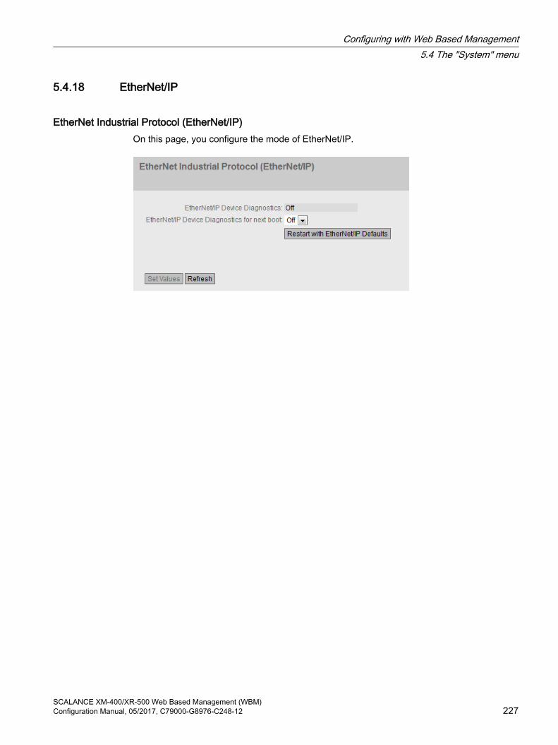
5.4.18 EtherNet/IP
EtherNet Industrial Protocol (EtherNet/IP)On this page, you configure the mode of EtherNet/IP.
Configuring with Web Based Management5.4 The "System" menu
SCALANCE XM-400/XR-500 Web Based Management (WBM)Configuration Manual, 05/2017, C79000-G8976-C248-12 227
DescriptionThe page contains the following boxes:
● EtherNet/IP Device DiagnosticsShows whether EtherNet/IP is enabled ("On") or disabled ("Off").
● EtherNet/IP Device Diagnostics for next bootSet whether EtherNet/IP will be enabled ("On") or disabled ("Off") after the next device restart.
NoteEtherNet/IP and PROFINET
When EtherNet/IP is turned on, PROFINET is turned off. The switchover from EtherNet/IP and PROFINET has no effect on DCP.
NotePROFINET AR Status
If a PROFINET connection is established; in other words the PROFINET AR status is "Online", you cannot enable EtherNet/IP.
● Restart with EtherNet/IP Defaults Click this button to restore the default settings of the EtherNet/IP profile and to restart the device. You must confirm the restart in a dialog box. The dialog box displays these settings specially made for operation with the EtherNet/IP protocol.
NOTICE
By resetting all the settings to the default settings of a profile, the IP address is also lost. Following this, the device can only be accessed via the serial interface, using the Primary Setup Tool or using DHCP.
With the appropriate attachment, a previously correctly configured device can cause circulating frames after the reset and therefore the failure of the data traffic.
5.4.19 PLUG
5.4.19.1 Configuration
NOTICE
Do not remove or insert a C-PLUG / KEY-PLUG during operation!
A PLUG may only be removed or inserted when the device is turned off.The device checks whether or not a PLUG is present at one second intervals. If it is detected that the PLUG was removed, there is a restart. If a valid KEY-PLUG was inserted in the device, the device changes to a defined error state following the restart.
Configuring with Web Based Management5.4 The "System" menu
SCALANCE XM-400/XR-500 Web Based Management (WBM)228 Configuration Manual, 05/2017, C79000-G8976-C248-12

Information about the configuration of the C-PLUG / KEY-PLUG This page provides detailed information about the configuration stored on the C-PLUG or KEY-PLUG. It is also possible to reset the PLUG to "factory defaults" or to load it with new contents.
Note
The action is only executed after you click the "Set Values" button.
The action cannot be undone.
If you decide against executing the function after making your selection, click the "Refresh" button. As a result the data of this page is read from the device again and the selection is canceled.
NoteIncompatibility with previous versions with PLUG inserted
During the installation of a previous version, the configuration data can be lost. In this case, the device starts up with the factory settings after the firmware has been installed. In this situation, if a PLUG is inserted in the device, following the restart, this has the status "Not Accepted" since the PLUG still has the configuration data of the previous more up-to-date firmware. This allows you to return to the previous, more up-to-date firmware without any loss of configuration data.
If the original configuration on the PLUG is no longer required, the PLUG can be deleted or rewritten manually using "System > PLUG".
Configuring with Web Based Management5.4 The "System" menu
SCALANCE XM-400/XR-500 Web Based Management (WBM)Configuration Manual, 05/2017, C79000-G8976-C248-12 229

Description of the displayed boxesThe table has the following rows:
● StatusShows the status of the PLUG. The following are possible:
– ACCEPTEDThere is a PLUG with a valid and suitable configuration in the device.
– NOT ACCEPTEDInvalid or incompatible configuration on the inserted PLUG.
– NOT PRESENTThere is no C-PLUG or KEY-PLUG inserted in the device.
– FACTORYPLUG is inserted and does not contain a configuration. This status is also displayed when the PLUG was formatted during operation.
– MISSINGThere is no PLUG inserted. Functions are configured on the device for which a license is required.
● Device GroupShows the SIMATIC NET product line that used the C-PLUG or KEY-PLUG previously.
Configuring with Web Based Management5.4 The "System" menu
SCALANCE XM-400/XR-500 Web Based Management (WBM)230 Configuration Manual, 05/2017, C79000-G8976-C248-12

● Device TypeShows the device type within the product line that used the C-PLUG or KEY-PLUG previously.
● Configuration RevisionThe version of the configuration structure. This information relates to the configuration options supported by the device and has nothing to do with the concrete hardware configuration. This revision information does not therefore change if you add or remove additional components (modules or extenders), it can, however, change if you update the firmware.
● File SystemDisplays the type of file system on the PLUG.
NOTICE
New file system UBI
As of firmware version 3.0, UBI is the standard file system for the C-PLUG or KEY-PLUG. If a C-PLUG with the previous file system IECP is detected in such a device, this C-PLUG will be formatted for the UBI file system and the data will be rewritten to the C-PLUG.
This change in the file system also occurs following a firmware update to V3.0. A downgrade to the previous version of the firmware then presents a problem. The firmware can neither read nor write the C-PLUG or KEY-PLUG and it is not even possible to "Erase PLUG to Factory Default".
● File System SizeDisplays the maximum storage capacity of the file system on the PLUG in bytes.
● File System UsageDisplays the storage space in use in the file system of the C-PLUG in bytes.
● Info StringShows additional information about the device that used the PLUG previously, for example, order number, type designation, and the versions of the hardware and software. The displayed software version corresponds to the version in which the configuration was last changed. With the "NOT ACCEPTED" status, further information on the cause of the problem is displayed.
● Firmware on PLUGWhen the function enabled, the firmware will be stored on the PLUG. This means that automatic firmware updates/downgrades can be made with the PLUG. The box "Infor String" shows whether or not the firmware is stored on the PLUG.
● "Modify PLUGSelect the setting from the drop-down list. You have the following options for changing the configuration on the C-PLUG or KEY-PLUG:
– Write Current Configuration to the PLUG This option is available only if the status of the PLUG is "NOT ACCEPTED" or "FACTORY".The configuration in the internal flash memory of the device is copied to the PLUG.
– Erase PLUG to factory defaultDeletes all data from the C-PLUG and triggers low-level formatting.
Configuring with Web Based Management5.4 The "System" menu
SCALANCE XM-400/XR-500 Web Based Management (WBM)Configuration Manual, 05/2017, C79000-G8976-C248-12 231
Steps in configuration1. You can only make settings in this box if you are logged on with administrator rights. Here,
you decide how you want to change the content of the PLUG.
2. If you want to save the firmware on the PLUG select the check box "Firmware on PLUG".
3. Select the required option from the "Modify PLUG" drop-down list.
4. Click the "Set Values" button.
5.4.19.2 License
NOTICE
Do not remove or insert a C-PLUG / KEY-PLUG during operation!
A PLUG may only be removed or inserted when the device is turned off.The device checks whether or not a PLUG is present at one second intervals. If it is detected that the PLUG was removed, there is a restart. If a valid KEY-PLUG was inserted in the device, the device changes to a defined error state following the restart.
If the device was configured at some time with a PLUG, the device can no longer be used without this PLUG. To be able to use the device again, reset the device to the factory settings.
NoteIncompatibility with previous versions with PLUG inserted
During the installation of a previous version, the configuration data can be lost. In this case, the device starts up with the factory settings after the firmware has been installed. In this situation, if a PLUG is inserted in the device, following the restart, this has the status "Not Accepted" since the PLUG still has the configuration data of the previous more up-to-date firmware. This allows you to return to the previous, more up-to-date firmware without any loss of configuration data.
If the original configuration on the PLUG is no longer required, the PLUG can be deleted or rewritten manually using "System > PLUG".
Information about the license of the KEY-PLUGA C-PLUG can only store the configuration of a device. In addition to the configuration, a KEY-PLUG also contains a license that enables certain functions of your SIMATIC NET device.
This page provides detailed information about the license on the KEY-PLUG. In this example, the KEY-PLUG contains the data for enabling the layer 3 functions of the device.
Configuring with Web Based Management5.4 The "System" menu
SCALANCE XM-400/XR-500 Web Based Management (WBM)232 Configuration Manual, 05/2017, C79000-G8976-C248-12
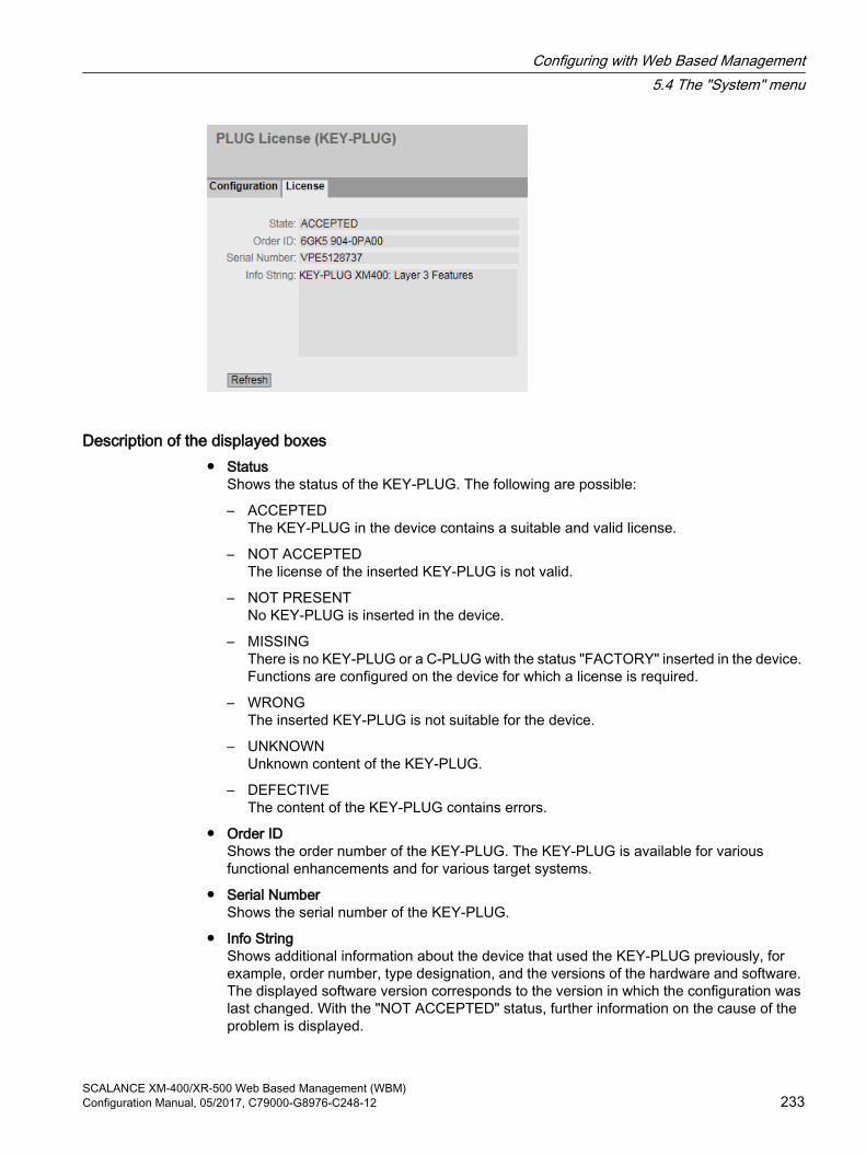
Description of the displayed boxes● Status
Shows the status of the KEY-PLUG. The following are possible:
– ACCEPTEDThe KEY-PLUG in the device contains a suitable and valid license.
– NOT ACCEPTEDThe license of the inserted KEY-PLUG is not valid.
– NOT PRESENTNo KEY-PLUG is inserted in the device.
– MISSINGThere is no KEY-PLUG or a C-PLUG with the status "FACTORY" inserted in the device. Functions are configured on the device for which a license is required.
– WRONGThe inserted KEY-PLUG is not suitable for the device.
– UNKNOWNUnknown content of the KEY-PLUG.
– DEFECTIVEThe content of the KEY-PLUG contains errors.
● Order IDShows the order number of the KEY-PLUG. The KEY-PLUG is available for various functional enhancements and for various target systems.
● Serial NumberShows the serial number of the KEY-PLUG.
● Info StringShows additional information about the device that used the KEY-PLUG previously, for example, order number, type designation, and the versions of the hardware and software. The displayed software version corresponds to the version in which the configuration was last changed. With the "NOT ACCEPTED" status, further information on the cause of the problem is displayed.
Configuring with Web Based Management5.4 The "System" menu
SCALANCE XM-400/XR-500 Web Based Management (WBM)Configuration Manual, 05/2017, C79000-G8976-C248-12 233

Note
When you save the configuration, the information about whether or not a KEY-PLUG was inserted in the device at the time is also saved. This configuration can then only work if a KEY-PLUG with the same order number / license is inserted.
5.4.20 Ping
Reachability of an address in an IP networkWith the ping function, you can check whether a certain IP address is reachable in the network.
DescriptionThe page contains the following boxes:
● Destination AddressEnter the IPV4, IPv6 address or the FQDN (Fully Qualified Domain Name) of the device.
● RepeatEnter the number of ping requests.
Configuring with Web Based Management5.4 The "System" menu
SCALANCE XM-400/XR-500 Web Based Management (WBM)234 Configuration Manual, 05/2017, C79000-G8976-C248-12

● DNS ResolutionSelect the IP address type in which an entered FQDN will be resolved.
– AutoIn this mode, the IP address type is selected automatically.
– IPv4The entered FQDN will be resolved in an IPv4 address.
– IPv6The entered FQDN will be resolved in an IPv6 address.
● Out Interface for IPv6This selection is only required when the destination address is a multicast or a link local address.
– "-" (factory setting)
– Select the relevant IPv6 interface.
● PingClick this button to start the ping function.
● Ping OutputThis box shows the output of the ping function.
● ClearClick this button to empty the "Ping Output" box.
5.4.21 PoE
Note
The "PoE" menu item is only displayed with devices that support PoE.
5.4.21.1 General
Settings for Power over Ethernet (PoE)On this page, you see information about the power that the IE switch supplies with PoE.
The SCALANCE XR-500 represents a PSE (Power Sourcing Equipment). With the SCALANCE XM-400, each group of four ports with PoE capability is known as a PSE. The displayed values apply only to the corresponding PSE.
Configuring with Web Based Management5.4 The "System" menu
SCALANCE XM-400/XR-500 Web Based Management (WBM)Configuration Manual, 05/2017, C79000-G8976-C248-12 235

Description of the displayed boxes● PSE (read-only)
Shows the number of the PSE.
● Maximum Power [W] (read-only)Maximum power that a PSE provides to supply PoE devices.The "Maximum Power" value can be set for a SCALANCE XM-400.
● Allocated Power [W] (read-only)Sum of the power reserved by the PoE devices according to the "Classification".
● Power in Use [W] (read-only)Sum of the power used by the end devices.
● Usage Threshold [%]As soon as the power being used by the end devices exceeds the percentage shown here, an event is triggered.
Power over Ethernet with SCALANCE XM-400 With a SCALANCE XM-400, you can use the "Power over Ethernet" function via the port extender PE408PoE.
PoE power supply
The connection of the PoE power supply is external. You can connect 2 PoE power supplies with each PE408PoE port extender. Each PE408PoE therefore has 2 PSE units (Power Sourcing Equipment) each with 4 ports.
Numbering of the PSE units
To be able to differentiate between the PSE units in the configuration, they are numbered:
Configuring with Web Based Management5.4 The "System" menu
SCALANCE XM-400/XR-500 Web Based Management (WBM)236 Configuration Manual, 05/2017, C79000-G8976-C248-12

Figure 5-8 SCALANCE XM-400 with 2 PE408PoE port extenders
If a PE408PoE is inserted in slot 2, its two PSE slots have indexes 1 and 2. If a PE408PoE is inserted in slot 3, its two PSE slots have indexes 3 and 4.
The numbering of the PSE units is decided by the slots. If there is a port extender without PoE in slot 2, and there is a PE408PoE in slot 3, the PSE units in slot 3 still have the indexes 3 and 4.
Figure 5-9 SCALANCE XM-400 with 2 port extenders (1 port extender without PoE and 1 PE408PoE)
With a SCALANCE XM416-4C with which you can only connect one port extender, the indexes of the PSE units are 1 and 2.
Power over Ethernet with SCALANCE XR528-6M and SCALANCE XR552-12MWith SCALANCE XR528-6M and SCALANCE XR552-12M only the module slots 1 to 3 can be fitted with PoE modules.
Configuring with Web Based Management5.4 The "System" menu
SCALANCE XM-400/XR-500 Web Based Management (WBM)Configuration Manual, 05/2017, C79000-G8976-C248-12 237

5.4.21.2 Port
Settings for the portsFor each individual PoE port, you can specify whether or not the power will be supplied via Ethernet. You can also set a priority for each connected powered device (PD). Devices for which a high priority was set, take preference over other devices for the power supply.On this page, you can see detailed information on the individual PoE ports.
Description of the displayed boxesThe page contains two tables. In table 1, you can make settings and assign them to all ports at the same time. In table 2, you can make different settings for each port.
Table 1 has the following columns:
● PortShows that the settings are valid for all ports.
● SettingSelect the required setting.If "No Change" is selected, the entry in table 2 remains unchanged.
● PrioritySelect the required priority.If "No Change" is selected, the entry in table 2 remains unchanged.
● TypeHere, you can enter a string to describe the connected device in greater detail. The maximum length is 255 characters.
● Use Custom Maximum PowerSelect whether the custom maximum power is used.If "No Change" is selected, the entry in table 2 remains unchanged.
Configuring with Web Based Management5.4 The "System" menu
SCALANCE XM-400/XR-500 Web Based Management (WBM)238 Configuration Manual, 05/2017, C79000-G8976-C248-12

● Custom Maximum Power [W]Enter the maximum power that a port makes available to supply a connected device.This value is only taken into account when the "Use Custom Maximum Power" check box is selected.If "No Change" is entered, the entry in table 2 remains unchanged
● Copy to TableIf you click the button, the settings are adopted for all ports of table 2.
Table 2 has the following columns:
● PortShows the configurable PoE ports.The port is made up of the module number and the port number, for example port 0.1 is module 0, port 1.
● SettingEnable the PoE power supply for this port or interrupt it.
● PriorityFrom the drop-down list, select which priority this port will have for the power supply.The following settings are possible, in ascending order of relevance:
– Low
– High
– Critical
If the power of the connected power supply is inadequate to supply all connected devices, devices with a higher priority are given preference.If the same priority is set for two ports, the port with the lower number will be preferred when necessary.
● TypeHere, you can enter a string to describe the connected device in greater detail. The maximum length is 255 characters.
● Use Custom Maximum PowerIf you enable this check box for a port, the user-defined maximum power is used.
● Custom Maximum Power [W]Enter the maximum power that a port makes available to supply a connected device.This value is only taken into account when the "Use Custom Maximum Power" check box is selected.The user-defined power is compared to the range of values of the class indicated by the connected device.
– If the user-defined power is within the class of the connected device, the user-defined value is used.
– If the user-defined power is above the class of the connected device, the highest value of the class is used.
– If the user-defined power is below the class of the connected device, the lowest value of the class is used.
If the power consumption of the connected device exceeds the defined or used maximum power, the connected device is turned off.
Configuring with Web Based Management5.4 The "System" menu
SCALANCE XM-400/XR-500 Web Based Management (WBM)Configuration Manual, 05/2017, C79000-G8976-C248-12 239

● Classification (read-only)The classification specifies the class of the device.
● Status (read-only)Shows the current status of the port.The following states are possible:
– disabledThe PoE power supply is deactivated for this port.
– deliveringThe PoE power supply is activated for this port and a device is connected.
– searchingThe PoE power supply is activated for this port but there is no device connected.
Note
If a device is connected to a port with PoE capability, a check is made to determine whether the power of the port is adequate for the connected device.
If the power of the port is inadequate, although PoE is enabled in "Setting", the port nevertheless has the status "disabled". This means that the port was disabled by the PoE power management.
● Power [mW] (read-only)Shows the power that the SCALANCE provides for this port.
● Voltage [V] (read-only)Shows the voltage applied to this port.
● Current [mA] (read-only)Shows the current with which a device connected to this port is supplied.
5.4.22 Port Diagnostics
5.4.22.1 Cable TesterWith this page, each individual Ethernet port can run independent fault diagnostics on the cable. This test is performed without needing to remove the cable, connect a cable tester and install a loopback module at the other end. Short-circuits and cable breaks can be localized to within a few meters.
Note
Please note that this test is permitted only when no data connection is established on the port to be tested.
If, however, there is a data connection to the port to be tested, this is briefly interrupted.
Automatic re-establishment of the connection can fail and then needs to be done manually.
Configuring with Web Based Management5.4 The "System" menu
SCALANCE XM-400/XR-500 Web Based Management (WBM)240 Configuration Manual, 05/2017, C79000-G8976-C248-12

DescriptionThe page contains the following boxes:
● PortSelect the required port from the drop-down list.
● Run TestActivates error diagnostics. The result is shown in the table.
This table contains the following columns:
● PairShows the wire pair in the cable.
NoteWire pairs
Wire pairs 4-5 and 7-8 of 10/100 Mbps network cables are not used.
1000 Mbps or gigabit Ethernet uses all 4 wire pairs.
The wire pair assignment - pin assignment is as follows (DIN 50173):
Pair 1 = pin 4-5
Pair 2 = pin 1-2
Pair 3 = pin 3-6
Pair 4 = pin 7-8
● StatusDisplays the status of the cable.
● Distance [m]Displays the distance to the cable end, cable break, or short-circuit.
Configuring with Web Based Management5.4 The "System" menu
SCALANCE XM-400/XR-500 Web Based Management (WBM)Configuration Manual, 05/2017, C79000-G8976-C248-12 241

5.4.22.2 SFP diagnosticsOn this page, you run independent error diagnostics for each individual SFP port. This test is performed without needing to remove the cable, connect a cable tester or install a loopback module at the other end.
DescriptionThe page contains the following boxes:
● PortSelect the required port from the drop-down list.
● RefreshRefreshes the display of the values of the set port. The result is shown in the table.
The values are shown in the following boxes:
● NameShows the name of the interface.
● ModelShows the type of interface.
● RevisionShows the hardware version of the SFP.
Configuring with Web Based Management5.4 The "System" menu
SCALANCE XM-400/XR-500 Web Based Management (WBM)242 Configuration Manual, 05/2017, C79000-G8976-C248-12

● SerialShows the serial number of the SFP.
● Nominal Bit Rate [Mbps]Shows the nominal bit rate of the interface.
● Max. Link (50.0/125um) [m]Shows the maximum distance in meters that is possible with this medium.
● Max. Link (62.5/125um) [m]Shows the maximum distance in meters that is possible with this medium.
The following table shows the values of the SFP transceiver used in this port:
● Temperature [°C]Shows the temperature of the interface.
● Voltage [V]Shows the voltage applied to the interface [V].
● Current [mA]Shows the current consumption of the interface [mA].
● Rx Power [μW]/Rx Power [dBm]Shows the receive power of the interface [μW]/[dBm].
● Tx Power [μW]/Tx Power [dBm]Shows the transmit power of the interface [μW]/[dBm].
● Current columnShows the current value.
● Low columnShows the lowest value.
● High columnShows the highest value.
5.4.23 Configuration Backup
Configuration Package BackupOn this page, you can save backups of your configuration.
The created backups are saved in the file type "ConfigPackBackup". On the "System > Load&Save > HTTP/TFTP > " page you can save configuration backups on your client PC or load them from there.
Configuring with Web Based Management5.4 The "System" menu
SCALANCE XM-400/XR-500 Web Based Management (WBM)Configuration Manual, 05/2017, C79000-G8976-C248-12 243

DescriptionThe page contains the following boxes:
● NameEnter a name for the backup.
This table contains the following columns:
● SelectSelect the row you want to delete.
● NameShows the name of the backup.
● Size [KB]The first row "Available memory" shows how much memory is available for backups on the device. When you create a backup, the available memory space is reduced accordingly.The other rows show the size of each backup.
● RestoreClick the "Restore" button to load the relevant backup on the device.
Procedure1. Enter the required name.
2. Click the "Create" button.The current configuration is saved as a configuration backup.Saving the backup may take some time. A new row is created for the backup. The size of the backup is displayed and subtracted from the available memory space.
Configuring with Web Based Management5.4 The "System" menu
SCALANCE XM-400/XR-500 Web Based Management (WBM)244 Configuration Manual, 05/2017, C79000-G8976-C248-12

5.5 The "Layer 2" menu
5.5.1 Configuration
Configuring layer 2On this page, you create a basic configuration for the functions of layer 2. On the configuration pages of these functions, you can make detailed settings. You can also check the settings on the configuration pages.
Description of the displayed boxes● Protocol Based VLAN
Enable or disable protocol-based VLAN. Other settings in "Layer 2 > VLAN".
● Subnet Based VLANEnable or disable subnet-based VLAN. Other settings in "Layer 2 > VLAN".
● Dynamic MAC AgingEnable or disable the "Aging" mechanism. You can configure other settings in "Layer 2 > Dynamic MAC Aging".
Configuring with Web Based Management5.5 The "Layer 2" menu
SCALANCE XM-400/XR-500 Web Based Management (WBM)Configuration Manual, 05/2017, C79000-G8976-C248-12 245

● Redundancy TypeThe following settings are available:
– "-" (disabled)The redundancy function is disabled.
– Spanning TreeIf you select this option, you specify the required redundancy mode in the "Redundancy Mode" drop-down list.
– RingIf you select this option, you specify the required redundancy mode in the "Redundancy Mode" drop-down list.
– Ring with RSTPIf you select this option, the compatibility mode for spanning tree is set permanently to RSTP. In the "Redundancy Mode" drop-down list, you specify the redundancy mode of the ring redundancy.You can change the current setting in the "Ring Redundancy" and "Spanning Tree" menus.
NoteRestriction relating to ports with the "Ring with RSTP" option
If you have enabled the "Ring with RSTP" option, the following ports must not be included in the spanning tree:● Ring ports● Standby ports● Standby coupling ports
Configuring with Web Based Management5.5 The "Layer 2" menu
SCALANCE XM-400/XR-500 Web Based Management (WBM)246 Configuration Manual, 05/2017, C79000-G8976-C248-12
● Redundancy ModeIf you select "Ring" or "Ring with RSTP"in the "Redundancy Type" drop-down list, the following options are then available:
– Automatic Redundancy DetectionSelect this setting to create an automatic configuration of the redundancy mode.In the "Automatic Redundancy Detection" mode, the device automatically detects whether or not there is a device with the "HRP Manager" role in the ring. If there is, the device adopts the role "HRP Client" client.If no HRP manager is found, all devices with the "Automatic Redundancy Detection" or "MRP Auto Manager" setting negotiate among themselves to establish which device adopts the role of "MRP Manager". The device with the lowest MAC address will always become "MRP Manager". The other devices automatically set themselves to "MRP Client" mode.
– MRP Auto-ManagerIn the "MRP Auto Manager" mode, the devices negotiate among themselves to establish which device will adopt the role of "MRP Manager". The device with the lowest MAC address will always become "MRP Manager". The other devices automatically set themselves to "MRP Client" mode.In contrast to the setting "Automatic Redundancy Detection", the devices are not capable of detecting whether or not an HRP manager is in the ring.
NoteMRP configuration in STEP 7
If you set the role "Manager (Auto)" or "Manager" for the device in STEP 7, in both cases, "MRP Auto Manager" is displayed on this WBM page. In the display in the CLI, a distinction is made between the two roles.
– MRP ClientThe device adopts the role of MRP client.
– HRP ClientThe device adopts the role of HRP client.
– HRP managerThe device adopts the role of HRP manager.When you configure an HRP ring, one device must be set as HRP manager. For all other devices, "HRP Client" or "Automatic Redundancy Detection" must be set.
If you select "Spanning Tree" in the "Redundancy Type" drop-down list, the following options are then available:
– STPEnabled Spanning Tree Protocol. Typical reconfiguration times with spanning tree are between 20 and 30 seconds. You can configure other settings in "Layer 2 > Spanning Tree".
Configuring with Web Based Management5.5 The "Layer 2" menu
SCALANCE XM-400/XR-500 Web Based Management (WBM)Configuration Manual, 05/2017, C79000-G8976-C248-12 247

– RSTP Enabled Rapid Spanning Tree Protocol (RSTP). If a spanning tree frame is detected at a port, this port reverts from RSTP to spanning tree. You can configure other settings in "Layer 2 > Spanning Tree".
Note
When using RSTP (Rapid Spanning Tree Protocol), loops involving duplication of frames or frames being overtaken may occur briefly. If this is not acceptable in your particular application, use the slower standard spanning tree mechanism.
– MSTPEnables Multiple Spanning Tree Protocol (MSTP). You can configure other settings in "Layer 2 > Spanning Tree".
If you select "Ring with RSTP" in the "Redundancy Type" drop-down list, the current redundancy modes of the Spanning tree and ring redundancy are displayed.
● StandbyEnable or disable the standby redundancy function. You will find other settings in "Layer 2 > Ring Redundancy"
● Passive ListeningEnable or disable the passive listening function.
● RMONIf you select this check box, Remote Monitoring (RMON) allows diagnostics data to be collected on the device, prepared and read out using SNMP by a network management station that also supports RMON. This diagnostic data, for example port-related load trends, allow problems in the network to be detected early and eliminated. Some of the "Ethernet statistics counters" are part of the RMON function. If you disable RMON, the "Ethernet statistics counter" in "Information > Ethernet statistics" is no longer updated.
● Dynamic Multicast The following settings are possible:
– "-" (disabled)
– IGMP SnoopingEnables IGMP (Internet Group Management Protocol). You can configure other settings in "Layer 2 > Multicast > IGMP".
– MLD SnoopingEnables MLD. You can configure other settings in "Layer 2 > Multicast > MLD".
– IGMP and MLD SnoopingEnables IGMP and MDL.
– GMRPEnables GMRP (GARP Multicast Registration Protocol). You can configure other settings in "Layer 2 > Multicast > GMRP".
Note
GMRP and IGMP cannot operate at the same time.
● GVRPEnable or disable "GVRP" (GARP VLAN Registration Protocol). You can configure other settings in "Layer 2 > VLAN > GVRP".
Configuring with Web Based Management5.5 The "Layer 2" menu
SCALANCE XM-400/XR-500 Web Based Management (WBM)248 Configuration Manual, 05/2017, C79000-G8976-C248-12

● Mirroring Enable or disable port mirroring. You can configure other settings in "Layer 2 > Mirroring".
● Loop DetectionEnable or disable the loop detection function. This allows loops in the network to be detected. You will find other settings in "Layer 2 > Loop Detection"
● PTPThe following setting is possible:
– offThe device does not process any PTP messages. PTP messages are, however, forwarded according to the rules of the switch.
– transparentThe device adopts the function of a transparent clock and forwards PTP messages to other nodes while at the same time making entries in the correction field of the PTP message.
You will find other settings in "Layer 2 > PTP"
5.5.2 QoS
5.5.2.1 CoS queue mapping
CoS queue Here, CoS priorities are assigned to certain queues (Traffic Queues).
Configuring with Web Based Management5.5 The "Layer 2" menu
SCALANCE XM-400/XR-500 Web Based Management (WBM)Configuration Manual, 05/2017, C79000-G8976-C248-12 249

Description of the displayed boxesThe table has the following columns:
● CoSShows the CoS priority of the incoming packets.
● QueueFrom the drop-down list, select the forwarding queue (send priority) that is assigned to the CoS priority. The higher the number of the queue, the higher the send priority. With queues 1 - 6 frames with a lower priority are occasionally processed even if there are frames with high priority in the queue.With queues 7 - 8 only frames with a high priority are processed as long as there are frames with high priority in the queue.
The service classes (CoS) are assigned to the queues as follows:
● CoS 0 → Queue 2
● CoS 1 → Queue 1
● CoS 2 → Queue 3
● CoS 3 → Queue 4
● CoS 4 → Queue 5
● CoS 5 → Queue 6
● CoS 6 → Queue 7
● CoS 7 → Queue 8
Steps in configuration1. For each value in the "CoS" column, select the forwarding queue from the "Queue" drop-
down list.
2. Click the "Set Values" button.
Configuring with Web Based Management5.5 The "Layer 2" menu
SCALANCE XM-400/XR-500 Web Based Management (WBM)250 Configuration Manual, 05/2017, C79000-G8976-C248-12

5.5.2.2 DSCP Mapping
DSCP MappingOn this page, DSCP settings are assigned to various queues (Traffic Queues).
Description of the displayed valuesThe table has the following columns:
● DSCPShows the DSCP priority of the incoming packets.
● QueueFrom the drop-down list, select the forwarding queue (send priority) that is assigned to the DSCP value.The higher the queue number, the higher the send priority.With queues 1 - 6 frames with a lower priority are occasionally processed even if there are frames with high priority in the queue.With queues 7 - 8 only frames with a high priority are processed as long as there are frames with high priority in the queue.
The DSCP codes are assigned to the queues as follows:
● DSCP codes 0 - 7 → Queue 2
● DSCP codes 8 - 15 → Queue 1
● DSCP codes 16 - 23 → Queue 3
● DSCP codes 24 - 31 → Queue 4
● DSCP codes 32 - 39 → Queue 5
● DSCP codes 40 - 47 → Queue 6
● DSCP codes 48 - 55 → Queue 7
Configuring with Web Based Management5.5 The "Layer 2" menu
SCALANCE XM-400/XR-500 Web Based Management (WBM)Configuration Manual, 05/2017, C79000-G8976-C248-12 251

● DSCP codes 56 - 63 → Queue 8
Steps in configuration1. For each value in the "DSCP" column, select the forwarding queue from the "Queue" drop-
down list.
2. Click the "Set Values" button.
5.5.2.3 QoS Trust
Specifying the subnet priorityOn this page you can set the method according to which frames to be forwarded are prioritized port by port.
Description of the displayed valuesTable 1 has the following columns:
● PortShows that the setting is valid for all ports of table 2.
● Trust ModeSelect the setting from the drop-down list. You have the following setting options:
– No Trust
– Trust COS
– Trust DSCP
– Trust COS-DSCP
– No ChangeTable 2 remains unchanged.
● Copy to TableIf you click the button, the setting is adopted for all ports of table 2.
Configuring with Web Based Management5.5 The "Layer 2" menu
SCALANCE XM-400/XR-500 Web Based Management (WBM)252 Configuration Manual, 05/2017, C79000-G8976-C248-12

Table 2 has the following columns:
● PortShows the configurable ports.The port is made up of the module number and the port number, for example port 0.1 is module 0, port 1.
● Trust ModeSelect the required mode from the drop-down list:
Note
You configure the prioritization of the receiving port on the page "Layer 2 > VLAN > Port Based VLAN".
You configure the assignment of the following priorities to a queue on the page ""Layer 2 > QoS > CoS Map".● Receiving port● VLAN tag● Broadcast and agent frame
You configure the assignment of the DSCP prioritization to a queue on the page ""Layer 2 > QoS > DSCP Mapping".
– No TrustThe switch sorts the incoming frames into a queue according to the prioritization of the receiving port.If there is a DSCP value in the IP header, this is ignored. If a VLAN tag exists, its priority value is replaced by the priority value of the receiving port.
– Trust COSIf an incoming frame contains a VLAN tag, the switch sorts it into a queue according to this prioritization.If the frame does not contain a VLAN tag, the switch sorts the frame into a queue according to the prioritization of the receiving port.If there is a DSCP value in the IP header, this is ignored.
– Trust DSCPIf an incoming frame contains a DSCP prioritization, the switch sorts it into a queue according to this prioritization.If the frame does not contain a DSCP prioritization, the switch sorts the frame into a queue according to the prioritization of the receiving port.If the frame contains a VLAN tag, this is ignored.
– Trust COS-DSCPWith an incoming frame, there is a sequential check of which prioritization it contains.If it contains a DSCP prioritization, it is handled as in the "Trust DSCP" mode.If it contains no DSCP prioritization, the switch checks whether it contains a VLAN tag. If it contains a VLAN tag, the switch sorts it into a queue according to this prioritization.If the frame contains neither a DSCP prioritization nor a VLAN tag, the switch sorts the frame into a queue according to the prioritization of the receiving port.
Configuring with Web Based Management5.5 The "Layer 2" menu
SCALANCE XM-400/XR-500 Web Based Management (WBM)Configuration Manual, 05/2017, C79000-G8976-C248-12 253

Steps in configuration1. Select the required Trust Mode from the drop-down list.
2. Click the "Set Values" button.
5.5.3 Rate Control
Limiting the transfer rate of incoming and outgoing dataOn this page, you configure the load limitation (maximum number of data packets per second) for the individual ports. You can specify the category of frame for which these limit values will apply.
Description of the displayed valuesTable 1 has the following columns:
● 1st columnShows that the settings are valid for all ports.
● Limit Ingress Unicast (DLF) / Limit Ingress Broadcast / Limit Ingress MulticastSelect the required setting in the drop-down list.
– enabled: Enables the function.
– disabled: Disables the function
– No Change: The setting in table 2 remains unchanged
● Total Ingress Rate [pkts/s]Specify the maximum number of incoming packets processed by the device. If "No Change" is entered, the entry in the table remains unchanged.
● Egress Rate kb/sSpecify the data rate for all outgoing frames. If "No Change" is entered, the entry in the table remains unchanged
● Copy to tableIf you click the button, the settings are adopted for all ports of table 2.
Configuring with Web Based Management5.5 The "Layer 2" menu
SCALANCE XM-400/XR-500 Web Based Management (WBM)254 Configuration Manual, 05/2017, C79000-G8976-C248-12

Table 2 has the following columns:
● PortShows the slot and the port to which the other information relates. This field cannot be configured. The port is made up of the module number and the port number, for example port 0.1 is module 0, port 1.
● Limit Ingress Unicast (DLF) Enable or disable the data rate for limiting incoming unicast frames with an unresolvable address (Destination Lookup Failure).
● Limit Ingress BroadcastEnable or disable the data rate for limiting incoming broadcast frames.
● Limit Ingress MulticastEnable or disable the data rate for limiting incoming multicast frames.
● Total Ingress Rate [pkts/s]Specify the maximum number of incoming packets processed by the device.
● Egress Rate kb/sSpecify the data rate for all outgoing frames.
NoteRounding of the values, deviation from desired value
When you input the rate values, note that the WBM rounds to correct values.
If values are configured for Total Ingress Rate and Egress Rate, the actual values in operation can deviate slightly from the set values.
Steps in configuration1. Enter the relevant values in the columns "Total Ingress Rate"and "Egress rate" in the row
of the port being configured.
2. To use the limitation for the incoming frames, select the check box in the row. For outgoing frames, the value in the "Egress Rate" column is used.
3. Click the "Set Values" button.
Configuring with Web Based Management5.5 The "Layer 2" menu
SCALANCE XM-400/XR-500 Web Based Management (WBM)Configuration Manual, 05/2017, C79000-G8976-C248-12 255

5.5.4 VLAN
5.5.4.1 General
VLAN configuration pageOn this page, you define the VLAN and specify the use of the ports.
NoteChanging the agent VLAN ID
If the configuration PC is connected directly to the device via Ethernet and you change the agent VLAN ID, the device is no longer reachable via Ethernet following the change.
Important rules for VLANsMake sure you keep to the following rules when configuring and operating your VLANs:
● Frames with the VLAN ID "0" are handled as untagged frames but retain their priority value.
● As default, all ports on the device send frames without a VLAN tag to ensure that the end node can receive these frames.
● With SCALANCE X devices, the VLAN ID "1" is the default on all ports.
● If an end node is connected to a port, outgoing frames should be sent without a tag (static access port). If, however, there is a further switch at this port, the frame should have a tag added (trunk port).
● With a trunk port, the VLAN assignment is dynamic. Static configurations can only be created if, in addition to the trunk port property, the port is also entered statically as a member in the VLANs involved. An example of a static configuration is the assignment of the multicast groups in certain VLANs.
Configuring with Web Based Management5.5 The "Layer 2" menu
SCALANCE XM-400/XR-500 Web Based Management (WBM)256 Configuration Manual, 05/2017, C79000-G8976-C248-12

Description of the displayed boxesThe page contains the following boxes:
● Bridge modeSelect the role of the device. The roles are are as follows:
– CustomerIf you operate the device with the "Customer" role, it behaves like a standard IE switch.
– ProviderIf you operate the device with the "Provider" role, in addition to the properties of the "Customer" role it it provides the option of managing external VLAN tags. With this role you can use the function Q-in-Q VLAN tunnel.
● VLAN IDEnter the VLAN ID in the "VLAN ID" input box. Range of values: 1 ... 4094
The table has the following columns:
● SelectSelect the row you want to delete.
● VLAN IDShows the VLAN ID. The VLAN ID (a number between 1 and 4094) can only be assigned once when creating a new data record and can then no longer be changed. To make a change, the entire data record must be deleted and created again. Up to 257 VLANs can be defined.
● NameEnter a name for the VLAN. The name only provides information and has no effect on the configuration. The length is a maximum of 32 characters.
● StatusShows the status type of the entry in the internal port filter table. Here, static means that the address was entered as a static address by the user. The entry GVRP means that the configuration was registered by a GVRP frame. This is, however, only possible if GVRP was enabled for the device.
● Private VLAN TypeShows the type of the PVLAN.
● Primary VLAN ID, With secondary PVLANs shows the ID of the corresponding primary PVLAN.
Configuring with Web Based Management5.5 The "Layer 2" menu
SCALANCE XM-400/XR-500 Web Based Management (WBM)Configuration Manual, 05/2017, C79000-G8976-C248-12 257

● TransparentIf you enable this check box, you switch a VLAN to the transparent mode. Ports that were assigned to this VLAN as members or untagged members now become transparent ports.This means the following:
– The port VLAN ID of the transparent port is set to the ID of this VLAN.
– Untagged frames that are received at these ports are forwarded to all other transparent ports once again without tag as long as they are not forwarded to a standard VLAN by a protocol or subnet rule.
– Frames tagged with VLAN ID "0" and that are received at these ports are forwarded to all other transparent ports once again tagged with VLAN ID "0" as long as they are not forwarded to a standard VLAN by a protocol or subnet rule.
– Frames tagged with the VLAN ID of the transparent VLAN and that are received at these ports are forwarded to all transparent ports once again tagged with the VLAN ID of the transparent VLAN.
– Other frames are forwarded according to the normal VLAN rules and a transparent port behaves like an untagged member in this VLAN.
– All ports that were not members or untagged members in the relevant VLAN are automatically set to the "Forbidden" status.
– As long as a VLAN is configured as a transparent VLAN, the ports belonging to this VLAN cannot be modified.
– You can only configure one a transparent VLAN.
Note
If you disable the transparent mode for a VLAN again, the previously written port configuration is retained.
● List of portsSpecify the use of the port. The following options are available:
– "-"The port is not a member of the specified VLAN.With a new definition, all ports have the identifier "-".
– MThe port is a member of the VLAN. Frames sent in this VLAN are forwarded with the corresponding VLAN tag.
– RThe port is a member of the VLAN. A GVRP frame is used for the registration.
– U (uppercase)The port is an untagged member of the VLAN. Frames sent in this VLAN are forwarded without the VLAN tag. Frames without a VLAN tag are sent from this port.
– u (lowercase)The port is an untagged member of the VLAN, but the VLAN is not configured as a port VLAN. Frames sent in this VLAN are forwarded without the VLAN tag.
Configuring with Web Based Management5.5 The "Layer 2" menu
SCALANCE XM-400/XR-500 Web Based Management (WBM)258 Configuration Manual, 05/2017, C79000-G8976-C248-12

– FThe port is not a member of the specified VLAN and it is not possible for the VLAN to be registered dynamically at this port using GVRP. If a port in a VLAN has this option, it cannot become a member of this VLAN even if it is configured as a trunk port.You can configure further settings in "Layer 2 > VLAN > Port-based VLAN".
– TThis option is only displayed and cannot be selected in the WBM. This port is a trunk port making it a member in all VLANs.You configure this function in the CLI (Command Line Interface) using the "switchport mode trunk" command.
Steps in configuration1. Enter an ID in the "VLAN ID" input box.
2. Click the "Create" button. A new entry is generated in the table. As default, the boxes have "-" entered.
3. Enter a name for the VLAN under Name.
4. Switch the VLAN to the transparent or standard compliant mode.
5. Specify the use of the port in the VLAN. If, for example you select M, the port is a member of the VLAN. The frame sent in this VLAN is forwarded with the corresponding VLAN tag.
6. Click the "Set Values" button.
5.5.4.2 GVRP
Configuration of GVRP functionalityUsing GVRP frame, a different device can register at the port of the device for a specific VID. A different device, can, for example be an end device or a switch. The device can also send GVRP frames via this port.
On this page, you can enable each port for GVRP functionality.
Configuring with Web Based Management5.5 The "Layer 2" menu
SCALANCE XM-400/XR-500 Web Based Management (WBM)Configuration Manual, 05/2017, C79000-G8976-C248-12 259

Description of the displayed boxesThe page contains the following box:
● GVRPEnable or disable the GVRP function.
Table 1 has the following columns:
● 1st columnShows that the settings are valid for all ports of table 2.
● SettingSelect the setting from the drop-down list. You have the following setting options:
– EnabledEnables the sending of GVRP frames.
– DisabledDisables the sending of GVRP frames.
– No changeNo change to table 2.
● Copy to Table If you click the button, the setting is adopted for all ports of table 2.
Table 2 has the following columns:
● PortShows the available ports. The port is made up of the module number and the port number, for example port 0.1 is module 0, port 1.
● SettingEnable or disable the sending GVRP frames.
Configuring with Web Based Management5.5 The "Layer 2" menu
SCALANCE XM-400/XR-500 Web Based Management (WBM)260 Configuration Manual, 05/2017, C79000-G8976-C248-12

Steps in configuration1. Click "GVRP" check box.
2. Click the check box after the port in the "Setting" column to enable or disable GVRP for this port.Repeat this for every port for which you want to enable or disable the function.
3. Click the "Set Values" button.
5.5.4.3 Port-based VLAN
Processing received framesOn this page, you specify the configuration of the port properties for receiving frames.
Description of the displayed boxesTable 1 has the following columns:
● PortShows that the settings are valid for all ports.
● Priority / / Port-VID / Acceptable Frames / Ingress FilteringSelect the setting in the drop-down list. If "No Change" is selected, the entry in table 2 remains unchanged.
● Copy to Table If you click the button, the setting is adopted for all ports of table 2.
Configuring with Web Based Management5.5 The "Layer 2" menu
SCALANCE XM-400/XR-500 Web Based Management (WBM)Configuration Manual, 05/2017, C79000-G8976-C248-12 261

Table 2 has the following columns:
● PortShows the available ports and link aggregations. The port is made up of the module number and the port number, for example port 0.1 is module 0, port 1.
● PriorityFrom the drop-down list, select the priority given to untagged frames. The CoS priority (Class of Service) used in the VLAN tag. If a frame is received without a tag, it will be assigned this priority. This priority specifies how the frame is further processed compared with other frames.There are a total of eight priorities with values 0 to 7, where 7 represents the highest priority (IEEE 802.1p Port Priority).
● Port VIDSelect the VLAN ID from the drop-down list. Only VLAN IDs defined on the "VLAN > General" page can be selected.If a received frame does not have a VLAN tag, it has a tag with the VLAN ID specified here added to it and is sent according to the rules at the port.
● Acceptable FramesSpecify which types of frames will be accepted. The following alternatives are possible:
– Tagged Frames OnlyThe device discards all untagged frames. Frames tagged with "0" are treated like untagged frames. The device forwards all tagged frames. Otherwise, the forwarding rules apply according to the configuration.
– Untagged and Priority Tagged OnlyThe device discards all tagged frames. The device forwards all untagged frames and frames with a priority (Priority Tagged Frames). Otherwise, the forwarding rules apply according to the configuration.If you have configured the Bridge mode "Provider" this means that the device treats all incoming frames like untagged frames.
– AllThe device forwards all frames.
● Ingress FilteringSpecify whether the VID of received frames is evaluatedYou have the following options:
– EnabledThe VLAN ID of received frames decides whether they are forwarded: To forward a VLAN tagged frame, the receiving port must be a member in the same VLAN. Frames from unknown VLANs are discarded at the receiving port.
– DisabledAll frames are forwarded.
Steps in configuration1. In the row of the port to be configured, click on the relevant cell in the table to configure it.
2. Enter the values to be set in the input boxes as follows.
Configuring with Web Based Management5.5 The "Layer 2" menu
SCALANCE XM-400/XR-500 Web Based Management (WBM)262 Configuration Manual, 05/2017, C79000-G8976-C248-12

3. Select the values to be set from the drop-down lists.
4. Click the "Set Values" button.
5.5.4.4 Protocol-based VLAN group
IntroductionOn this page, you specify groups and assign a protocol to them.
Description of the displayed boxesThe page contains the following boxes:
● Protocol-based VLANEnable or disable the protocol-based VLAN assignment.
● Protocol ValueEnter the hexadecimal protocol value. A few examples are shown below:
– PROFINET: 88:92
– IP: 08:00
– Novell: 81:37
– netbios: f0:f0
– appletalk: 80:9b
● Group IDEnter the ID of the group.
Configuring with Web Based Management5.5 The "Layer 2" menu
SCALANCE XM-400/XR-500 Web Based Management (WBM)Configuration Manual, 05/2017, C79000-G8976-C248-12 263

The table has the following columns:
● SelectSelect the row you want to delete.
● Protocol ValueShows the protocol value.
● Group IdentifierShows the group ID.
Steps in configurationAdding an entry
1. Enter the protocol value in the "Protocol Value" input box.
2. Enter the ID for the group in the Group Identifier input box.
3. Click the "Create" button. A new entry is generated in the table.
4. Click the "Set Values" button.
Deleting an entry
1. On the "Protocol-based VLAN port" tab, check that the protocol group is not used at any port.
2. Select the check box in the row to be deleted.
3. Click the "Delete" button.
4. Click the "Set Values" button.
5.5.4.5 Protocol-based VLAN port
IntroductionOn this page, you specify which protocol and which VLAN is assigned to the individual port.
Configuring with Web Based Management5.5 The "Layer 2" menu
SCALANCE XM-400/XR-500 Web Based Management (WBM)264 Configuration Manual, 05/2017, C79000-G8976-C248-12

Description of the displayed boxesThe page contains the following boxes:
● PortSelect the port in the drop-down list. All available ports and the link aggregations can be selected.
● Group IdentifierSelect the group ID in the drop-down list. You specify the ID the WBM page "Protocol Based VLAN Group".
The table has the following columns:
● SelectSelect the row you want to delete.
● PortAll available ports and the link aggregations are displayed.
● Group IdentifierShows the group ID assigned to the port.
● VLAN IDFrom the drop-down list, select the VLAN ID you want to assign to the port.
Steps in configuration1. Select the port from the "Port" drop-down list.
2. Select the group ID from the "Group Identifier" drop-down list.
3. Click the "Create" button. A new entry is generated in the table.
4. Specify the VLAN ID in " VLAN ID".
5. Click the "Set Values" button.
Configuring with Web Based Management5.5 The "Layer 2" menu
SCALANCE XM-400/XR-500 Web Based Management (WBM)Configuration Manual, 05/2017, C79000-G8976-C248-12 265

5.5.4.6 IPv4 subnet-based VLAN
IntroductionOn this page, you specify which VLAN ID is assigned to the subnet.
Description of the displayed boxesThe page contains the following boxes:
● Subnet-based VLANEnable or disable the IPv4 subnet-based VLAN assignment.
● PortSelect the port in the drop-down list. All available ports and the link aggregations can be selected.
● Subnet AddressEnter the IPv4 address of the subnet.Example: 192.168.10.0 for the network 192.168.10.x with nodes 192.168.10.1 to 192.168.10.254.
● Subnet MaskEnter the subnet mask.
The table has the following columns:
● SelectSelect the row you want to delete.
● PortAll available ports and the link aggregations are displayed.
● Subnet AddressShows the subnet address assigned to the port.
Configuring with Web Based Management5.5 The "Layer 2" menu
SCALANCE XM-400/XR-500 Web Based Management (WBM)266 Configuration Manual, 05/2017, C79000-G8976-C248-12

● Subnet MaskShows the subnet mask assigned to the port.
● VLAN IDSelect the VLAN ID you want to assign to the port or the subnet.
Steps in configuration1. Select a port from the "Port" drop-down list.
2. Enter the subnet address.in "Subnet Address".
3. In "Subnet Mask", enter the subnet mask.
4. Click the "Create" button. A new entry is generated in the table.
5. Select the VLAN ID from the "VLAN ID" drop down list.
6. Click the "Set Values" button.
5.5.4.7 IPv6 prefix-based VLAN
IntroductionOn this page, you specify which VLAN ID is assigned to the IPv6 prefix.
Description of the displayed boxesThe page contains the following boxes:
● PortSelect the port in the drop-down list. All available ports and the link aggregations can be selected.
● Prefix AddressEnter the IPv6 address.
Configuring with Web Based Management5.5 The "Layer 2" menu
SCALANCE XM-400/XR-500 Web Based Management (WBM)Configuration Manual, 05/2017, C79000-G8976-C248-12 267

● Prefix LengthEnter the number of left-hand bits belonging to the prefix
● VLAN IDSelect the VLAN ID you want to assign to the port or the prefix.
The table has the following columns:
● SelectSelect the row you want to delete.
● PortAll available ports and the link aggregations are displayed.
● Prefix AddressShows the IPv6 address of the port.
● Prefix LengthShows the prefix length.
● VLAN IDSelect the VLAN ID you want to assign to the port or the prefix.
Steps in configuration1. Select a port from the "Port" drop-down list.
2. Enter the IPv6 address in "Prefix Address".
3. Enter the prefix length in "Prefix Length".
4. Select the VLAN ID from the "VLAN ID" drop down list.
5. Click the "Create" button. A new entry is generated in the table.
Configuring with Web Based Management5.5 The "Layer 2" menu
SCALANCE XM-400/XR-500 Web Based Management (WBM)268 Configuration Manual, 05/2017, C79000-G8976-C248-12

5.5.5 Private VLAN
5.5.5.1 General
Private VLAN configuration pageOn this page you define the types of the PVLANs and assign secondary PVLANs to a primary PVLAN.
Description of the displayed boxesThe table has the following columns:
● VLAN IDShows the VLAN ID.
● Private VLAN TypeSpecify the type of PVLAN:
– -These VLANs are not private VLANs.
– PrimaryWith this type, you define a primary PVLAN. In a PVLAN you can only define one primary PVLAN. The primary PVLAN uses the VLAN ID of the VLAN.
– IsolatedWith this type, you define a secondary PVLAN. Devices within an isolated secondary PVLAN cannot communicate with each other via layer 2. The secondary PVLAN has a specific VLAN ID.
– CommunityWith this type, you define a secondary PVLAN. The devices in this secondary PVLAN can communicate with each other via layer 2. The secondary PVLAN has a specific VLAN ID.
● Primary VLAN ID For secondary PVLANs select the VLAN ID of the primary PVLAN.
Configuring with Web Based Management5.5 The "Layer 2" menu
SCALANCE XM-400/XR-500 Web Based Management (WBM)Configuration Manual, 05/2017, C79000-G8976-C248-12 269
Steps in configuration1. Create the required VLANs on the page "Layer 2 > VLAN > General".
Note
All secondary PVLANs must be known on all IE switches of a PVLAN. Even if an IE switch has no host port in a secondary PVLAN, the secondary PVLAN must be known on the IE switch.
2. Change to the page "Layer 2 > Private VLAN > General". A line is created there for every VLAN.
3. On this page, you specify the "Private VLAN Type".
4. Click the "Set Values" button.
5. For the secondary PVLANs specify the corresponding primary PVLAN.
6. Click the "Set Values" button.
7. For the required ports select the corresponding port type on the page "System > Ports > Configuration":
– Switch-Port PVLAN Promiscuous
– Switch Port VLAN Host
8. Specify the use of the ports on the page "Layer 2 > VLAN > General".
– For promiscuous ports that are connected to other promiscuous ports, select the setting "M" in all PVLANs.
– For promiscuous ports that are connected to an end device, select the setting "u" (lower case) in all PVLANs.In the primary PVLAN, the setting is automatically changed to "U" (upper case) after saving.
– For host ports in the primary PVLAN and in its secondary PVLAN, select the setting "u" (lower case)In its secondary PVLAN, the setting is automatically changed to "U" (upper case) after saving.
With incoming untagged frames, the port VLAN-ID of the VLAN is set by entering the port with the setting "U" (upper case).
5.5.5.2 IP Interface Mapping
Private VLAN configuration pageOn this page you specify from which secondary PVLANs the IP interface of the primary PVLAN will be reachable.
Configure the IP interface assignment for all functions for which an end device needs to communicate from the secondary PVLAN via the IP interface of the primary PVLAN.
Configuring with Web Based Management5.5 The "Layer 2" menu
SCALANCE XM-400/XR-500 Web Based Management (WBM)270 Configuration Manual, 05/2017, C79000-G8976-C248-12

Examples:
● An end device in the secondary PVLAN is configured as DHCP client. A remote DHCP server is set up. A PVLAN switch is configured as DHCP relay agent. Configure an IP interface in the primary PVLAN of the DHCP relay agent. Assign the secondary PVLANs containing DHCP clients to this IP interface.
● A PVLAN switch is configured as router. Configure an IP interface in the primary PVLAN of the router. Assign the secondary PVLANs containing end devices that use the router as a gateway to this IP interface.
Description of the displayed boxesThe page contains the following boxes:
● InterfaceSelect the primary PVLAN with an IP interface.
● Secondary VLAN IDSelect a secondary VLAN ID from which the IP interface of the primary PVLAN will be reachable.
The table has the following columns:
● SelectSelect the row you want to delete.
● InterfaceShows the IP interface.
● Secondary VLAN-IDShows the secondary VLAN-ID of the secondary PVLAN from which the IP interface of the primary PVLAN is reachable.
Steps in configuration1. Create an IP interface for the primary PVLAN.
2. Select the primary PVLAN with an IP interface.
Configuring with Web Based Management5.5 The "Layer 2" menu
SCALANCE XM-400/XR-500 Web Based Management (WBM)Configuration Manual, 05/2017, C79000-G8976-C248-12 271

3. Select a secondary VLAN ID.
4. Click the "Create" button.
5.5.6 Provider bridge
5.5.6.1 Tunnel ports
Configuration page for tunnel portsOn this page, you enable the Q-in-Q VLAN tunnel function. Frames received by a tunnel port are expanded by an external VLAN tag, the PVID of the port.
Description of the displayed boxesTable 1 has the following columns:
● 1st columnShows that the settings are valid for all ports of table 2.
● SettingSelect the setting from the drop-down list. You have the following setting options:
– EnabledEnables the Q-in-Q VLAN tunnel function on all ports.
– DisabledDisables the Q-in-Q VLAN tunnel function on all ports.
– No ChangeTable 2 remains unchanged.
● Copy to TableIf you click the button, the settings are adopted for all ports of table 2.
Configuring with Web Based Management5.5 The "Layer 2" menu
SCALANCE XM-400/XR-500 Web Based Management (WBM)272 Configuration Manual, 05/2017, C79000-G8976-C248-12

Table 2 has the following columns:
● PortShows all available ports. The port is made up of the module number and the port number, for example port 0.1 is module 0, port 1.
● SettingEnable or disable the function for this port.
Steps in configurationTo configure a port as a tunnel port proceed as follows:
1. Change to the page "Layer 2 > VLAN > General".
2. Configure the Bridge mode "Provider".
3. Click the "Set Values" button.The layer 2 port settings (VLAN, Spanning Tree) are restored to the factory defaults and the device is restarted.
4. Change to the page "Layer 2 > VLAN > General".
5. Enter the required VLAN ID.
6. Click the "Create" button.
7. Change to the page "Layer 2 > VLAN > Port Based VLAN".
8. For the port select the port VID of the created VLAN.
9. For the port in "Acceptable Frames" select the setting "Untagged and Priority Tagged Only".
10.Click the "Set Values" button.
11.Change to the page "Layer 2 > VLAN > General".
12.For the port in the required VLAN, select the setting "U" (uppercase).
13.For the port in all other VLANs, select the setting "-".
14.Click the "Set Values" button.
15.Disable the following protocols on the port:
– On the page "Layer 2 > VLAN > GVRP" the check box beside "Setting".
– On the page "Layer 2 > Spanning Tree > CIST Port" the check box beside "Spanning Tree Status".
– On the page "Layer 2 > Multicast > GMRP" the check box beside "Setting".
16.Change to the page "System > Ports > Configuration"
17.Select the required port.
18.Select the Port Type "Switch-Port PVLAN Access".
19.Click the "Set Values" button.
20.Change to the page "Layer 2 > Provider-Bridge > Tunnel-Ports".
Configuring with Web Based Management5.5 The "Layer 2" menu
SCALANCE XM-400/XR-500 Web Based Management (WBM)Configuration Manual, 05/2017, C79000-G8976-C248-12 273

21.Select the check box for the required port.
22.Click the "Set Values" button.On the page "Layer 2 > VLAN > General", after you save, the setting will be changed automatically to "Q".
5.5.7 Mirroring
5.5.7.1 General
Note
It cannot be guaranteed when mirroring the data traffic that all packets are mirrored. This depends primarily on the load on the mirrored ports and on the number of sessions. To achieve maximum precision, a limit of one session is recommended.
Mirroring in generalOn this page, you can enable or disable the "Mirroring" function and make the basic settings.
Note
Mirroring a port does not work beyond switch core boundaries. Refer to the operating instructions of the device.
Note
You need to disable port mirroring if you want to connect a normal end device to the monitor port. This does not apply to the function extender BUS ANALYZER Agent XM-400.
Note the data rateIf the maximum data rate of the mirrored port is higher than that of the monitor port, data may be lost and the monitor port no longer reflects the data traffic at the mirrored port. Several ports can be mirrored to one monitor port at the same time.
Configuring with Web Based Management5.5 The "Layer 2" menu
SCALANCE XM-400/XR-500 Web Based Management (WBM)274 Configuration Manual, 05/2017, C79000-G8976-C248-12

Settings
Configuring with Web Based Management5.5 The "Layer 2" menu
SCALANCE XM-400/XR-500 Web Based Management (WBM)Configuration Manual, 05/2017, C79000-G8976-C248-12 275

The page contains the following boxes:
● MirroringClick this check box to enable or disable mirroring.
● Monitor BarrierClick this check box to enable or disable Monitor Barrier
NoteEffects of monitor barrier
If you enable this option, management of the switch via the monitor port is no longer reachable. The following port-specific functions are changed:● The DCP forwarding is turned off.● LLDP is turned off.● Unicast, multicast and broadcast blocking is turned on.
The previous statuses of these functions are no longer restored after disabling monitor barrier again. They are reset to the default values and may need to be reconfigured.
You can reconfigure these functions manually even if monitor barrier is turned on. The data traffic on the monitor port is also allowed again. If you do not require this, make sure that only the data traffic you want to monitor is forwarded to the interface.
If mirroring is disabled, the listed port-specific functions are reset to the default values. This reset takes place regardless of whether the functions were configured manually or automatically by enabling "monitor barrier".
NoteFunction Extender BUS ANALYZER Agent XM-400
If the destination port is a port of the function extender BUS ANALYZER Agent XM-400 the monitor barrier option is always activated. It is activated regardless of whether the check box was disabled or enabled.
● RSPAN VLAN-IDSelect a VLAN on which the data traffic of a mirroring session is transferred without disruption.
The table for the basic settings contains the following boxes:
● Select Select the row you want to delete.
● Session IDThe Session ID is assigned automatically when a new entry is created.
Configuring with Web Based Management5.5 The "Layer 2" menu
SCALANCE XM-400/XR-500 Web Based Management (WBM)276 Configuration Manual, 05/2017, C79000-G8976-C248-12

● Session TypeSelect the required entry from the drop-down list:
– -None
– Port BasedPort-based mirroring
– VLANVLAN-based mirroring
– MAC ACLMirroring of the MAC Access Control List
– IP ACLMirroring of the IP Access Control List
Note
If you have created a session of the type "VLAN" "MAC ACL" or "IP ACL", you cannot create any further sessions. You can create up to 7 sessions of the type "Port-based".
Note
If you change the "Session Type" of an existing session, all previous configurations of this session are lost.
● StatusShows whether or not mirroring is enabled.
● Hardware IndexIf in a VLAN you select more than one source port for the port-based egress mirroring, unknown unicast and multicast frames as well as broadcast frames are forwarded only once to the destination port. With several sessions, the corresponding frames are only visible in one session. They are only mirrored on the destination port with the lowest hardware index.
● Dest. PortFrom the drop-down list, select the destination port to which data will be mirrored in this session.
NoteFunction Extender BUS ANALYZER Agent XM-400
If you connect a function extender BUS ANALYZER Agent XM-400 with a SCALANCE XM-400 basic device, you can select up to four ports of the function extender BUS ANALYZER Agent XM-400 as destination ports. Function extender BUS ANALYZER Agent XM-400 supports port-based, VLAN-based, MAC ACL-based and IP ACL-based mirroring.
● RSPANEnable or disable RSPAN for a session.
Configuring with Web Based Management5.5 The "Layer 2" menu
SCALANCE XM-400/XR-500 Web Based Management (WBM)Configuration Manual, 05/2017, C79000-G8976-C248-12 277

ProcedureCreating a mirroring session
1. Activate mirroring.
2. Click the "Create" button to create a further entry in the table.The session ID is assigned automatically. Depending on the session type selected, you can create one or more mirroring sessions.
3. Select a "Session Type".
4. Click the "Set Values" button.
5. Select a destination port.
6. Click the "Set Values" button to save and activate the selected settings.
7. Change to the following tabs to make further detailed settings for the relevant session ID.
Deleting a mirroring session
1. Click the check box in the first column to select the row.
2. Click the "Delete" button to delete the selected rows.
Mirroring with RSPAN
1. Create a VLAN for the RSPAN data traffic on all devices involved.
Note
You can only create one RSPAN VLAN.
2. Create a mirroring session.
3. Select the "RSPAN VLAN ID".
4. Enable the check box in the "RSPAN" column.
5. Click the "Set Values" button to save the selected settings.
Configuring with Web Based Management5.5 The "Layer 2" menu
SCALANCE XM-400/XR-500 Web Based Management (WBM)278 Configuration Manual, 05/2017, C79000-G8976-C248-12

5.5.7.2 Port
Mirroring portsYou can only configure the settings on this page if you have already generated a session ID with the session type "Port-based" on the "General" tab.
Description of the displayed boxesThe page contains the following drop down list:
● Session IDSelect the session you want to monitor. Up to 7 parallel sessions are possible and their ports must not overlap.
The table has the following columns:
● PortShows the available ports. The port is made up of the module number and the port number, for example port 0.1 is module 0, port 1.
● Ingress MirroringEnable or disable listening in on incoming packets at the required port.
● Egress MirroringEnable or disable listening in on outgoing packets at the required port.
Configuring with Web Based Management5.5 The "Layer 2" menu
SCALANCE XM-400/XR-500 Web Based Management (WBM)Configuration Manual, 05/2017, C79000-G8976-C248-12 279
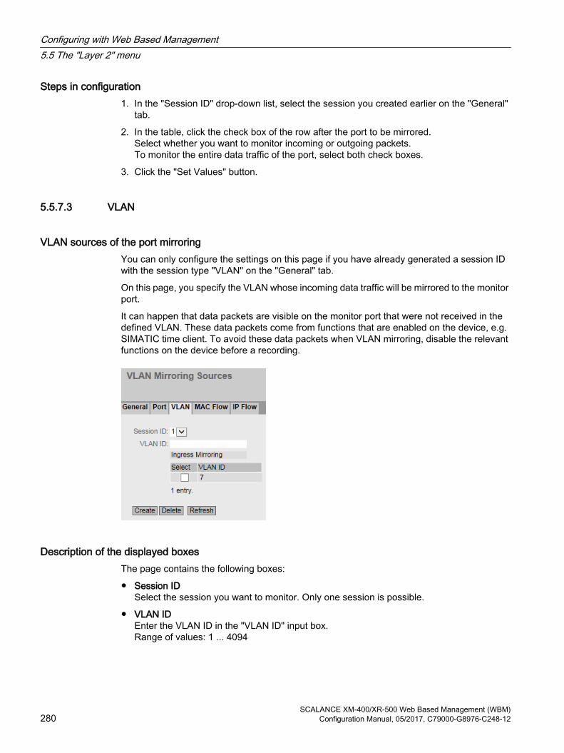
Steps in configuration1. In the "Session ID" drop-down list, select the session you created earlier on the "General"
tab.
2. In the table, click the check box of the row after the port to be mirrored.Select whether you want to monitor incoming or outgoing packets.To monitor the entire data traffic of the port, select both check boxes.
3. Click the "Set Values" button.
5.5.7.3 VLAN
VLAN sources of the port mirroringYou can only configure the settings on this page if you have already generated a session ID with the session type "VLAN" on the "General" tab.
On this page, you specify the VLAN whose incoming data traffic will be mirrored to the monitor port.
It can happen that data packets are visible on the monitor port that were not received in the defined VLAN. These data packets come from functions that are enabled on the device, e.g. SIMATIC time client. To avoid these data packets when VLAN mirroring, disable the relevant functions on the device before a recording.
Description of the displayed boxesThe page contains the following boxes:
● Session IDSelect the session you want to monitor. Only one session is possible.
● VLAN IDEnter the VLAN ID in the "VLAN ID" input box. Range of values: 1 ... 4094
Configuring with Web Based Management5.5 The "Layer 2" menu
SCALANCE XM-400/XR-500 Web Based Management (WBM)280 Configuration Manual, 05/2017, C79000-G8976-C248-12

The table "Ingress Mirroring " has the following columns:
● SelectSelect the row you want to delete.
● VLAN IDShows the VLAN ID for which the incoming frames are mirrored. The VLAN ID (a number between 1 and 4094) can only be assigned once when creating a new data record and can then no longer be changed. To make a change, the entire data record must be deleted and created again.
5.5.7.4 MAC Flow
ACL filter for port mirroringYou can only configure the settings on this page if you have already generated a session ID with the session type " "MAC ACL" on the "General" tab.
The ACL filter decides which data is available at the monitor port.
Description of the displayed boxes● Session ID
Select the session you want to monitor. Only one session is possible.
● ACL Filter NumberShows the number of the ACL filter.
● Ingress MirroringShows whether incoming packets are mirrored.
NoteRules
The selected rule only becomes active when you specify with which ACL rules the incoming packets will be filtered for at least one interface. You configure the settings in "Security > MAC ACL > Ingress Rules".
● Source MACShows the MAC address of the sender.
Configuring with Web Based Management5.5 The "Layer 2" menu
SCALANCE XM-400/XR-500 Web Based Management (WBM)Configuration Manual, 05/2017, C79000-G8976-C248-12 281

● Dest. MACShows the MAC address of the recipient.
● Ingress InterfacesShows all interfaces to which this rule applies. The ACL filter decides which incoming data streams are mirrored on the monitor port (destination port).
● Egress InterfacesShows all interfaces to which this rule applies.
5.5.7.5 IP Flow
ACL filter for port mirroringYou can only configure the settings on this page if you have already generated a session ID with the session type " "IP ACL" on the "General" tab.
The ACL filter decides which data is available at the monitor port.
Description of the displayed boxes● Session ID
Select the session you want to monitor. Only one session is possible.
● ACL Filter NumberShows the number of the ACL filter.
● Ingress MirroringShows whether incoming packets are mirrored.
NoteRules
The selected rule only becomes active when you specify with which ACL rules the incoming packets will be filtered for at least one interface. You configure the settings in "Security > IP ACL > Ingress Rules".
● Source IPShows the IPv4 address of the destination device.
● Source Subnet MaskShows the subnet mask of the sender.
Configuring with Web Based Management5.5 The "Layer 2" menu
SCALANCE XM-400/XR-500 Web Based Management (WBM)282 Configuration Manual, 05/2017, C79000-G8976-C248-12

● Dest. IPShows the IPv4 address of the recipient.
● Dest. Subnet MaskShows the subnet mask of the recipient.
● Ingress InterfacesShows all interfaces to which this rule applies. The ACL filter decides which incoming data streams are mirrored on the monitor port (destination port).
● Egress InterfacesShows all interfaces to which this rule applies.
5.5.8 Dynamic MAC Aging
Protocol settings and switch functionalityThe device automatically learns the source addresses of the connected nodes. This information is used to forward data frames to the nodes specifically involved. This reduces the network load for the other nodes.If a device does not receive a frame whose source address matches a learnt address within a certain time, it deletes the learnt address. This mechanism is known as "Aging". Aging prevents frames being forwarded incorrectly, for example when an end device is connected to a different switch port.If the check box is not enabled, a device does not delete learnt addresses automatically.
Description of the displayed boxesThe page contains the following boxes:
● Dynamic MAC AgingEnable or disable the function for automatic aging of learned MAC addresses.
● Aging Time[s]Enter the time in seconds. After this time, a learned address is deleted if the device does not receive any further frames from this sender address.Range of values: 10 - 630 (seconds)
Configuring with Web Based Management5.5 The "Layer 2" menu
SCALANCE XM-400/XR-500 Web Based Management (WBM)Configuration Manual, 05/2017, C79000-G8976-C248-12 283

Steps in configuration1. Select the "Dynamic MAC Aging" check box.
2. Enter the time in seconds in the "Aging Time[s]" input box.
3. Click the "Set Values" button.
5.5.9 Ring redundancy
5.5.9.1 Ring
Rules for ring redundancyFactory settings
● The factory setting defines MSTP as the redundancy method.
● With SCALANCE XM-400, the factory setting defines ports P1.1 and P1.2 as ring ports.
● With SCALANCE XR-500, the factory setting defines ports P0.1 and P0.2 as ring ports.
Enabling redundancy
You can enable ring redundancy as follows:
● using the WBM
● using the CLI
● using the SELECT/SET button
● using a PROFINET configuration download
Configuration of ring redundancy
Configuring with Web Based Management5.5 The "Layer 2" menu
SCALANCE XM-400/XR-500 Web Based Management (WBM)284 Configuration Manual, 05/2017, C79000-G8976-C248-12

● Ring RedundancyIf you enable the "Ring Redundancy" check box, you turn ring redundancy on. The ring ports set on this page are used.
● Ring redundancy modeHere, you set the mode of the ring redundancy.The following modes are available:
– Automatic Redundancy DetectionSelect this setting to create an automatic configuration of the redundancy mode.In the "Automatic Redundancy Detection" mode, the device automatically detects whether or not there is a device with the "HRP Manager" role in the ring. If there is, the device adopts the role "HRP Client".If no HRP manager is found, all devices with the "Automatic Redundancy Detection" or "MRP Auto Manager" setting negotiate among themselves to establish which device adopts the role of "MRP Manager". The device with the lowest MAC address will always become "MRP Manager". The other devices automatically set themselves to the "MRP Client" mode.
– MRP Auto-ManagerIn the "MRP Auto Manager" mode, the devices negotiate among themselves to establish which device will adopt the role of "MRP Manager". The device with the lowest MAC address will always become "MRP Manager". The other devices automatically set themselves to "MRP Client" mode.In contrast to the setting "Automatic Redundancy Detection", the devices are not capable of detecting whether or not an HRP manager is in the ring.
NoteMRP configuration in STEP 7
If you set the role "Manager (Auto)" or "Manager" for the device in STEP 7, in both cases, "MRP Auto Manager" is displayed on this WBM page. In the display in the CLI, a distinction is made between the two roles.
– MRP ClientThe device adopts the role of MRP client.
– HRP ClientThe device adopts the role of HRP client.
– HRP ManagerThe device adopts the role of HRP manager.When you configure an HRP ring, one device must be set as HRP manager. For all other devices, "HRP Client" or "Automatic Redundancy Detection" must be set.
● Ring portsHere, you set the ports to be used as ring ports in ring redundancy.The ring port you select in the left-hand drop-down menu is the "Isolated Port" in HRP.With MRP when the link is established, it is decided which port will become the "Isolated Port".
Configuring with Web Based Management5.5 The "Layer 2" menu
SCALANCE XM-400/XR-500 Web Based Management (WBM)Configuration Manual, 05/2017, C79000-G8976-C248-12 285

● ObserverEnable or disable the observer. The "Observer" function is only available in HRP rings.The ring port selected in the left-hand drop-down menu is connected to the "Isolated Port" of an HRP manager.The observer monitors malfunctions of the redundancy manager or incorrect configurations of an HRP ring.If the observer is enabled, it can interrupt the connected ring if errors are detected. To do this, the observer switches a ring port to the "blocking" status. When the error is resolved, the observer enables the port again.
● Restart ObserverIf numerous errors occur in quick succession, the observer no longer enables its port automatically. The ring port remains permanently in the "blocking" status. This is signaled by the error LED and a message text.After the errors have been eliminated, you can enable the port again using the "Restart Observer" button.
Restoring factory settingsIf you have restored the factory defaults, ring redundancy is disabled and the default ports are used as the ring ports. This can lead to circulating frames and failure of the data traffic if other settings were used in a previous configuration.
Changing over the status of the ring ports with the redundancy managerIf you configure a redundancy manager, set the status of the ring ports. With HRP the first ring port changes to the "blocking" status and the second ring port to the "forwarding" status. As long as ring redundancy is enabled, you cannot change the status of these ring ports.
Note
Make sure that you first open the ring so that there are no circulating frames.
Changing ring portsYou can change the ring ports without needing to open the ring.
To change the ring ports, follow the steps below:
1. Change to the page "Layer 2 > Spanning Tree > CIST Port".
2. Disable the ports in the spanning tree you want to configure as ring ports.
3. Change to the page "Layer 2 > Ring Redundancy > Ring".
4. Select the new ring ports.
5. Change the cable connections.
6. Change to the page "Layer 2 > Spanning Tree > CIST Port".
7. Enable the ports in the spanning tree that are no longer ring ports.
Configuring with Web Based Management5.5 The "Layer 2" menu
SCALANCE XM-400/XR-500 Web Based Management (WBM)286 Configuration Manual, 05/2017, C79000-G8976-C248-12

5.5.9.2 Standby
Redundant linking of ringsStandby redundancy allows the redundant linking of HRP rings.
To establish a standby connection, configure two neighboring devices within a ring as standby master or standby slave. The standby master and the standby slave must be connected via parallel cables to two devices in another ring.
In problem-free operation, messages are exchanged between the two rings via the master. If the master's line is disturbed, the slave takes over the forwarding of messages between the two rings.
Enable standby redundancy for both standby partners and select the ports via which the device is connected to the rings you want to link to.
For the "Standby Connection Name", a name unique within the ring must be assigned for both partners. This identifies the two modules that belong together as standby partners.
Note
To be able to use the function, HRP must be activated.
The standby manager always requires an activated HRP client.
NoteStandby master coupling with an optical 100 Mbps connection
While the coupling partner of a standby master with an optical 100 Mbps connection starts up again, physically disconnect the connection between the standby master and its coupling partner.
Configuring with Web Based Management5.5 The "Layer 2" menu
SCALANCE XM-400/XR-500 Web Based Management (WBM)Configuration Manual, 05/2017, C79000-G8976-C248-12 287

Description of the displayed boxes● Standby
Click the check box to enable or disable the function.
Note
If two devices are linked by the standby function, the "Standby" function must be enabled on both devices.
● Standby PortSelect the port to be standby port. The link to the other ring is via the standby port.
NoteStandby ports in the spanning tree
Before you enable the port as the standby port, you need to disable the port in the spanning tree.1. Change to the page "Layer 2 > Spanning Tree > CIST Port".2. Disable the ports in the spanning tree you want to configure as standby ports.
The standby port is involved in the redirection of data traffic. In there are no problems, only the standby port of the master is enabled and handles the data traffic into the connected HRP ring or HRP bus.If the master or the Ethernet connection (link) of one of the standby ports of the master fails, all standby ports of the master will be disabled and all standby ports of the slave enabled. As a result, a functioning Ethernet connection to the connected network segment (HRP ring or HRP linear bus) is restored.
● Standby Connection NameThis name defines the master/slave device pair. Both devices must be located in the same ring.Here, enter the name for the standby connection. This must be identical to the name entered on the standby partner. You can select any name to suit your purposes, however, you can only use the name for one pair of devices in the entire network.
Configuring with Web Based Management5.5 The "Layer 2" menu
SCALANCE XM-400/XR-500 Web Based Management (WBM)288 Configuration Manual, 05/2017, C79000-G8976-C248-12

● Force device to Standby MasterIf you select this check box, the device is configured as a standby master regardless of its MAC address.
– If this check box is not selected for either of the devices for which the standby master is enabled, then assuming that no error has occurred, the device with the higher MAC address adopts the role of standby master.
– If the option is selected for both devices or if the "Force device to Standby Master" property is supported by only one device, the standby master is also selected based on the MAC address.
This type of assignment is important in particular when a device is replaced. Depending on the MAC addresses, the previous device with the slave function can take over the role of the standby master.
Note
If the option "Force device to Standby Master" is enabled on both devices of a standby coupling, this can lead to circulating frames and therefore to failure of the data traffic. Enable the "Force device to Standby Master" option only on one device of a standby coupling.
● Wait for Standby Partner
– EnabledA standby connection is enabled only after the standby master and the standby slave as well as their standby partners have established a connection. This ensures that the redundant connection is really available before communication via a standby connection is enabled.
– DisabledA standby connection is enabled even if the standby master has not yet established a connection to the standby slave.This can lead to circulating frames and failure of the data traffic if another standby connection has already been enabled. Multiple standby connections can, for example, result due to configuration errors if different standby connection names were assigned to the standby master and standby slave.
Configuring with Web Based Management5.5 The "Layer 2" menu
SCALANCE XM-400/XR-500 Web Based Management (WBM)Configuration Manual, 05/2017, C79000-G8976-C248-12 289

5.5.9.3 Link Check
Requirements● You cannot enable Link Check on ports with 10 Gbps.
● You can only enable the Link Check function with optical ring ports of an HRP or MRP ring.
NoteReplacing: media modules: Optical → electrical
If you run Link Check on an optical port of a media module, not the following:● Link Check is activated on the optical port of a media module.● You want to replace the media module with a module without optical ports.1. Disable the link check on the ports of the inserted module.2. Replace the media module.
● Link Check must be enabled on two neighboring devices (connection partners) within an HRP or MRP ring.
● The ring ports on which you enable Link Check must be connected.
Monitoring optical connections in the ringWith the Link Check function, you can monitor the transmission quality of optical sections within an HRP or MRP ring, identify disturbed connections and under certain conditions turn them off. When the disturbed section is turned off, the redundancy manager can close the ring and restore communication.
NOTICE
Make sure that the frames used by Link Check for monitoring the optical connections are not supplanted by an overload of high priority frames in the network.
An overload of high priority frames can, for example, be caused by the following:● Network loops that can cause duplication of the high priority frames● Changing the priorities for forwarding frames
Note
Enable Link Check on only one of two connection partners This can lead to incorrect behavior.
Note
If Link Check is enabled on all devices of a ring at the same time, and several connections within the ring have problems, this leads to fragmentation of the ring.1. During commissioning enable the Link Check function for one connection section after the
other by enabling Link Check for the two connection partners connected to a line.2. To ensure an error-free connection, wait 1 min. before you enable Link Check for the next
connection.
Configuring with Web Based Management5.5 The "Layer 2" menu
SCALANCE XM-400/XR-500 Web Based Management (WBM)290 Configuration Manual, 05/2017, C79000-G8976-C248-12

Description of the displayed boxesThis table contains the following columns:
● PortShows the available ports. The port is made up of the module number and the port number, for example port 0.1 is module 0, port 1.
● SettingWith this check box, you enable or disable the Link Check function for a port.When connection monitoring is enabled, you can see the number of sent and received Link Check test frames on the "Information > Redundancy > Link Check” page.
● ResetAfter resetting Link Check, the function is restarted on the port and the statistics are reset.If you use the “Reset” button, the reset must be performed on both connection partners within 30 s.
Note
When you use the “Reset” button, loops can form temporarily resulting in a loss of data traffic. The loop is automatically cleared again.
If this is not acceptable for your application, reset Link Check by pulling the cable and plugging it in again.
Steps in configurationEnabling Link Check
Follow the steps below to activate the monitoring of a ring port:
1. Select the appropriate check box in the "Setting" column.
2. Click the "Set Values" button.
Disabling Link Check
Follow the steps below to deactivate the monitoring of a ring port:
1. Deactivate the appropriate check box in the "Setting" column.
2. Click the "Set Values" button.
Configuring with Web Based Management5.5 The "Layer 2" menu
SCALANCE XM-400/XR-500 Web Based Management (WBM)Configuration Manual, 05/2017, C79000-G8976-C248-12 291

5.5.10 Spanning tree
5.5.10.1 General
General settings of spanning treeThis is the basic page for spanning tree. Select the compatibility mode from the drop-down list.
On the configuration pages of these functions, you can make further settings.
Depending on the compatibility mode, you can configure the corresponding function on the relevant configuration page.
Description of the displayed boxesThe page contains the following boxes:
● Spanning TreeEnable or disable Spanning Tree.
● Protocol CompatibilitySelect the protocol compatibility. The following settings are available:
– STP
– RSTP
– MSTP
Steps in configuration1. Select the "Spanning Tree" check box.
2. From the "Protocol Compatibility" drop-down list, select the type of compatibility.
3. Click the "Set Values" button.
Configuring with Web Based Management5.5 The "Layer 2" menu
SCALANCE XM-400/XR-500 Web Based Management (WBM)292 Configuration Manual, 05/2017, C79000-G8976-C248-12

5.5.10.2 CIST General
MSTP-CIST configuration The page consists of the following parts.
● The left-hand side of the page shows the configuration of the device.
● The central part shows the configuration of the root bridge that can be derived from the spanning tree frames received by an device.
● The right-hand side shows the configuration of the regional root bridge that can be derived from the MSTP frames. The displayed data is only visible if you have enabled "Spanning Tree"on the "General" page and if "MSTP" is set for "Protocol Compatibility". This also applies to the "Bridge Max Hop Count" parameter. If the device is a root bridge, the information on the left and right matches.
Description of the displayed boxesThe page contains the following boxes:
● Bridge Priority / Root PriorityThe Bridge Priority decides which device becomes the Root Bridge. The Bridge with the highest priority becomes the Root Bridge. The lower the value, the higher the priority. If several devices in a network have the same priority, the device whose MAC address has the lowest numeric value will become the root bridge. Both parameters, bridge priority and MAC address together form the bridge identifier. Since the root bridge manages all path changes, it should be located as centrally as possible due to the delay of the frames.The value for the bridge priority is a whole multiple of 4096. Range of values: 0 - 61440
● Bridge Address / Root AddressThe bridge address shows the MAC address of the device and the root address shows the MAC address of the root bridge.
Configuring with Web Based Management5.5 The "Layer 2" menu
SCALANCE XM-400/XR-500 Web Based Management (WBM)Configuration Manual, 05/2017, C79000-G8976-C248-12 293

● Root port Shows the port via which the switch communicates with the root bridge.
● Root Cost The path costs from this device to the root bridge.
● Topology Changes / Last Topology ChangeThe entry for the device shows the number of reconfiguration actions due to the spanning tree mechanism since the last startup. For the root bridge, the time since the last reconfiguration is displayed as follows:
– Seconds: Unit "sec" after the number
– Minutes: Unit min after the number
– Hours: Unit hr after the number
● Bridge hello time [s] / Root hello time [s]Each bridge sends configuration frames (BPDUs) regularly. The interval between two configuration frames is the "Hello Time".Factory setting: 2 seconds
Note
The setting of the "Bridge Hello Time" is only possible with the Protocol compatibility RSTP. If the "Protocol compatibility MSTP is set, the "Hello Time" parameter on the page "Layer 2 > Spanning Tree > CIST Port" page is used.
● Bridge Forward Delay[s] / Root Forward Delay[s]New configuration data is not used immediately by a bridge but only after the period specified in the Forward Delay parameter. This ensures that operation is only started with the new topology after all the bridges have the required information.Factory setting: 15 seconds
● Bridge Max Age[s] / Root Max Age[s]If the BPDU is older than the specified "Max Age" it is discarded.Factory setting: 20 seconds
● Regional root priorityFor a description, see Bridge Priority / Root Priority
● Regional Root AddressThe MAC address of the device.
● Regional Root CostThe path costs from this device to the root bridge.
● Bridge Max Hop CountThis parameter specifies how many MSTP nodes a BPDU may pass through. If an MSTP BPDU is received and has a hop count that exceeds the value configured here, it is discarded. The default for this parameter is 20.
● Region NameEnter the name of the MSTP region to which this device belongs. As default, the MAC address of the device is entered here. This value must be the same on all devices that belong to the same MSTP region.
Configuring with Web Based Management5.5 The "Layer 2" menu
SCALANCE XM-400/XR-500 Web Based Management (WBM)294 Configuration Manual, 05/2017, C79000-G8976-C248-12

● Region VersionEnter the version number of the MSTP region in which the device is located. This value must be the same on all devices that belong to the same MSTP region.
● Reset CountersClick this button to reset the counters on this page.
Steps in configuration1. Enter the data required for the configuration in the input boxes.
2. Click the "Set Values" button.
5.5.10.3 CIST Port
MSTP-CIST port configuration When the page is called, the table displays the current status of the configuration of the port parameters.
To configure them, click the relevant cells in the port table.
Configuring with Web Based Management5.5 The "Layer 2" menu
SCALANCE XM-400/XR-500 Web Based Management (WBM)Configuration Manual, 05/2017, C79000-G8976-C248-12 295

Description of the displayed boxesTable 1 has the following columns:
● 1st columnShows that the settings are valid for all ports of table 2.
● Spanning Tree StatusSelect the setting from the drop-down list. You have the following setting options:
– EnabledPort is integrated in the spanning tree.
– DisabledPort is not integrated in the spanning tree.
– No changeTable 2 remains unchanged.
● Copy to TableIf you click the button, the setting is adopted for all ports of table 2.
Table 2 has the following columns:
● PortShows the available ports. The port is made up of the module number and the port number, for example port 0.1 is module 0, port 1.
● Spanning Tree StatusSpecify whether or not the port is integrated in the spanning tree.
Note
If you disable the "Spanning Tree Status" option for a port, this may cause the formation of loops. The topology must be kept in mind.
● PriorityEnter the priority of the port. The priority is only evaluated when the path costs are the same.The value must be divisible by 16. If the value that cannot be divided by 16, the value is automatically adapted.Range of values: 0 - 240. The default is 128.
● Cost Calc.Enter the path cost calculation. If you enter the value "0" here, the automatically calculated value is displayed in the "Path costs" box.
Configuring with Web Based Management5.5 The "Layer 2" menu
SCALANCE XM-400/XR-500 Web Based Management (WBM)296 Configuration Manual, 05/2017, C79000-G8976-C248-12

● Path CostThis parameter is used to calculate the path that will be selected. The path with the lowest value is selected as the path. If several ports of a device have the same value for the path costs, the port with the lowest port number is selected.If the value in the Cost Calc." is "0", the automatically calculated value is shown. Otherwise, the value of the "Cost Calc." box is displayed.The calculation of the path costs is largely based on the transmission speed. The higher the achievable transmission speed is, the lower the value of the path costs.Typical values for path costs with rapid spanning tree:
– 10,000 Mbps = 2,000
– 1000 Mbps = 20,000
– 100 Mbps = 200,000
– 10 Mbps = 2,000,000
The values can, however, also be set individually.
● StatusDisplays the current status of the port. The values are only displayed and cannot be configured. The "Status" parameter depends on the configured protocol. The following values are possible:
–DisabledThe port only receives and is not involved in STP, MSTP and RSTP.
– DiscardingIn the "Discarding" mode, BPDU frames are received. Other incoming or outgoing frames are discarded.
– Listening
In this status, BPDUs are both received and sent. The port is involved in the spanning tree algorithm.
–LearningStage prior to the "Forwarding" status, the port is actively learning the topology (in other words, the node addresses).
–ForwardingFollowing the reconfiguration time, the port is active in the network; it receives and forwards data frames.
● Fwd. TransSpecifies the number of changes from the "Discarding" status to the "Forwarding" status.
Configuring with Web Based Management5.5 The "Layer 2" menu
SCALANCE XM-400/XR-500 Web Based Management (WBM)Configuration Manual, 05/2017, C79000-G8976-C248-12 297
● Edge TypeSpecify the type of "edge port". You have the following options:
– "-"Edge port is disabled. The port is treated as a "no Edge Port".
– AdminSelect this option when there is always an end device on this port. Otherwise a reconfiguration of the network will be triggered each time a connection is changed.
– AutoSelect this option if you want a connected end device to be detected automatically at this port. When the connection is established the first time, the port is treated as a "no Edge Port".
– Admin/AutoSelect these options if you operate a combination of both on this port. When the connection is established the first time, the port is treated as an "Edge Port".
● EdgeShows the status of the port.
– Enabled
An end device is connected to this port.
– DisabledThere is a Spanning Tree or Rapid Spanning Tree device at this port.
With an end device, a switch can change over the port faster without taking into account spanning tree frames. If a spanning tree frame is received despite this setting, the port automatically changes to the "Disabled" setting.
Configuring with Web Based Management5.5 The "Layer 2" menu
SCALANCE XM-400/XR-500 Web Based Management (WBM)298 Configuration Manual, 05/2017, C79000-G8976-C248-12

● P.t.P. TypeSelect the required option from the drop-down list. The selection depends on the port that is set.
– "-"Point to point is calculated automatically. If the port is set to half duplex, a point-to-point link is not assumed.
– P.t.P.
Even with half duplex, a point-to-point link is assumed.
–Shared MediaEven with a full duplex connection, a point-to-point link is not assumed.
Note
Point-to-point connection means a direct connection between two devices. A shared media connection is, for example, a connection to a hub.
● Hello Time Enter the interval after which the bridge sends configuration frames (BPDUs). As default, 2 seconds is set. Range of values: 1-2 seconds
Note
The port-specific setting of the Hello time is only possible with Protocol compatibility MSTP. If the "Protocol compatibility RSTP is set, the "Bridge Hello Time" parameter on the page "Layer 2 > Spanning Tree > CIST General" page is used.
Steps in configuration1. In the input cells of the table row, enter the values of the port you are configuring.
2. From the drop-down lists of the cells of the table row, select the values of the port you are configuring.
3. Click the "Set Values" button.
Configuring with Web Based Management5.5 The "Layer 2" menu
SCALANCE XM-400/XR-500 Web Based Management (WBM)Configuration Manual, 05/2017, C79000-G8976-C248-12 299

5.5.10.4 MST General
Multiple Spanning Tree configurationWith MSTP, in addition to RSTP, several VLANs can be managed in a LAN with separate RSTP trees.
DescriptionThe page contains the following box:
● MSTP Instance IDEnter the number of the MSTP instance.Permitted values: 1 - 64
The table has the following columns:
● SelectSelect the row you want to delete.
● MSTP instance IDShows the number of the MSTP instance.
● Root AddressShows the MAC address of the root bridge.
● Root PriorityShows the priority of the root bridge.
● Bridge PriorityEnter the bridge priority in this box. The value for the bridge priority is a whole multiple of 4096 with a range of values from 0 to 61440.
● VLAN ID Enter the VLAN ID. Here, you can also specify ranges with Start ID, "-", End ID. Several ranges or IDs are separated by ",". Permitted values: 1- 4094
Configuring with Web Based Management5.5 The "Layer 2" menu
SCALANCE XM-400/XR-500 Web Based Management (WBM)300 Configuration Manual, 05/2017, C79000-G8976-C248-12

ProcedureCreating a new entry
1. Enter the number of the MSTP instance in the "MSTP Instance ID" box.
2. Click the "Create" button.
3. Enter the ID of the VLAN in the "VLAN ID" box.
4. Enter the priority of the bridge in the "Bridge Priority" box.
5. Click the "Set Values" button.
Deleting entries
1. Use the check box at the beginning of the relevant row to select the entries to be deleted.
2. Click the "Delete" button to delete the selected entries from memory. The entries are deleted from the memory of the device and the display on this page is updated.
5.5.10.5 MST Port
Configuration of the Multiple Spanning Tree port parameters On this page, you set the parameters for the ports of the configured multiple spanning tree instances.
Description of the displayed boxesThe page contains the following box:
● MSTP Instance IDIn the drop-down list, select the ID of the MSTP instance.
Configuring with Web Based Management5.5 The "Layer 2" menu
SCALANCE XM-400/XR-500 Web Based Management (WBM)Configuration Manual, 05/2017, C79000-G8976-C248-12 301

Table 1 has the following columns:
● 1st columnShows that the settings are valid for all ports.
● MSTP StatusSelect the setting from the drop-down list. You have the following setting options:
– Enabled
– Disabled
– No Change: Table 2 remains unchanged.
● Copy to TableIf you click the button, the setting is adopted for all ports of table 2.
Table 2 has the following columns:
● PortShows all available ports and link aggregations.
● MSTP Instance ID ID of the MSTP instance.
● MSTP Status Click the check box to enable or disable this option.
● PriorityEnter the priority of the port. The priority is only evaluated when the path costs are the same.The value must be divisible by 16. If the value that cannot be divided by 16, the value is automatically adapted.Range of values: 0 - 240. Factory setting: 128
● Cost Calc.Enter the path cost calculation in the input box. If you enter the value "0" here, the automatically calculated value is displayed in the next box "Path Costs".
● Path costThe path costs from this port to the root bridge. The path with the lowest value is selected as the path. If several ports of a device have the same value, the port with the lowest port number will be selected.If the "Cost Calc." is "0", the automatically calculated value is shown. Otherwise, the value of the "Cost Calc." box is displayed.The calculation of the path costs is largely based on the transmission speed. The higher the achievable transmission rate, the lower the value for the path costs will be.Typical values for rapid spanning tree are as follows:
– 10,000 Mbps = 2,000
– 1000 Mbps = 20,000
– 100 Mbps = 200,000
– 10 Mbps = 2,000,000
The values can, however, also be set individually.
Configuring with Web Based Management5.5 The "Layer 2" menu
SCALANCE XM-400/XR-500 Web Based Management (WBM)302 Configuration Manual, 05/2017, C79000-G8976-C248-12

● StatusDisplays the current status of the port. The values are only displayed and cannot be configured. The following is possible for status:
– DiscardingThe port exchanges MSTP information but is not involved in the data traffic.
– BlockedIn the blocking mode, BPDU frames are received.
– ForwardingThe port receives and sends data frames.
● Fwd. Trans.Specifies the number of status changes Discarding - Forwarding or Forwarding - Discarding for a port.
Steps in configuration1. In the input cells of the table row, enter the values of the port you are configuring.
2. From the drop-down lists of the cells of the table row, select the values of the port you are configuring.
3. Click the "Set Values" button.
5.5.10.6 Enhanced Passive Listening Compatibility
Enabling the functionOn this page, you can enable passive listening compatibility.
Configuring with Web Based Management5.5 The "Layer 2" menu
SCALANCE XM-400/XR-500 Web Based Management (WBM)Configuration Manual, 05/2017, C79000-G8976-C248-12 303

Description of the displayed boxesThe page contains the following boxes:
● Enhanced Passive Listening CompatibilityEnable or disable this function for the entire device.
● Setting
– EnabledEnables the function for all ports of the device.
– DisabledDisables the function for all ports of the device.
– No ChangeNo Change
● Copy to TableWrites the setting made in "Setting" to the following table
Port-specific table:If the function is enabled for the entire device, enable or disable this function on individual ports.
● PortDisplays the port of the device.
● SettingEnable or disable the function for this port.
Steps in configurationEnable the function for the entire device
1. Enable or disable "Enhanced Passive Listening Compatibility"
2. Click the "Set Values" button.
For all ports of the device:
1. From the drop-down list, select whether the function should be enabled or disabled or adopted unchanged.
2. Click the "Copy to Table" button.
3. Click the "Set Values" button.
For individual ports of the device:
1. Click the check box after the required port in the port table to enable or disable the function.
2. Click the "Set Values" button.
5.5.11 Loop DetectionWith the "Loop detection" function, you specify the ports for which loop detection will be activated. The ports involved send special test frames - the loop detection frames. If these frames are sent back to the device, there is a loop.
Configuring with Web Based Management5.5 The "Layer 2" menu
SCALANCE XM-400/XR-500 Web Based Management (WBM)304 Configuration Manual, 05/2017, C79000-G8976-C248-12
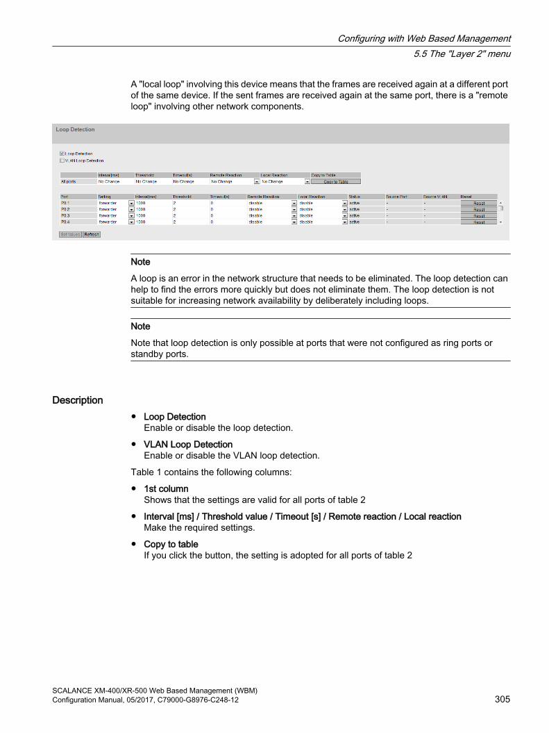
A "local loop" involving this device means that the frames are received again at a different port of the same device. If the sent frames are received again at the same port, there is a "remote loop" involving other network components.
Note
A loop is an error in the network structure that needs to be eliminated. The loop detection can help to find the errors more quickly but does not eliminate them. The loop detection is not suitable for increasing network availability by deliberately including loops.
Note
Note that loop detection is only possible at ports that were not configured as ring ports or standby ports.
Description ● Loop Detection
Enable or disable the loop detection.
● VLAN Loop DetectionEnable or disable the VLAN loop detection.
Table 1 contains the following columns:
● 1st columnShows that the settings are valid for all ports of table 2
● Interval [ms] / Threshold value / Timeout [s] / Remote reaction / Local reactionMake the required settings.
● Copy to tableIf you click the button, the setting is adopted for all ports of table 2
Configuring with Web Based Management5.5 The "Layer 2" menu
SCALANCE XM-400/XR-500 Web Based Management (WBM)Configuration Manual, 05/2017, C79000-G8976-C248-12 305

Table 2 contains the following columns:
● PortShows the available ports.
● SettingSpecify how the port handles loop detection frames. Select one of the following options from the drop-down list:
Note
Test frames create additional network load. We recommend that you only configure individual switches, for example at branch points of the ring, as "Sender" and the others as "Forwarder".
– SenderLoop detection frames are sent out and forwarded.
– ForwarderLoop detection frames from other devices are forwarded.
– blockedThe forwarding of loop detection frames is blocked.
● Interval [ms]Specifies the send interval for loop detection frames in milliseconds.
● ThresholdBy entering a number, specify the number of received loop detection frames as of which a loop is assumed.
● Timeout [s]Specifies the number of seconds after which the device automatically changes to the status in which it was before the loop. If the value "0" is set, you need to enable the port manually again following a loop with the "Reset" button.
● Remote reactionSpecify how the port will react if a remote loop occurs. Select one of the two options from the drop-down list:
– No Change: A loop has no effect on the port.
– disabled: The port is blocked.
● Local reactionSpecify how the port will react if a local loop occurs. Select one of the two options from the drop-down list:
– No Change: A loop has no effect on the port.
– disabled: The port is blocked
● StatusThis box shows whether loop detection is enabled or disabled for this port.
● Source PortShows the receiving port of the loop detection frame that triggered the last reaction.
Configuring with Web Based Management5.5 The "Layer 2" menu
SCALANCE XM-400/XR-500 Web Based Management (WBM)306 Configuration Manual, 05/2017, C79000-G8976-C248-12

● Source VLANThis box shows the VLAN ID of the loop detection frame that triggered the last reaction. This requires that the "VLAN Loop Detection" check box is selected.
● ResetAfter a loop in the network has been eliminated, click this button "Reset to reset the port again.
Changing the configured port status with loop detectionThe configuration of the port status can be changed with the "Loop Detection" function. If, for example, the administrator has disabled a port, the port can be enabled again after a device restart with "Loop Detection”. The port status "Link down" is not changed by "Loop Detection".
Effects of configuration using STEP 7The configuration of Spanning Tree can be changed if you configure "Loop Detection" using STEP 7.
If you enable "Loop Detection" on a port with STEP 7, Spanning Tree is automatically disabled on this port. If you disable "Loop Detection" for the port again with STEP 7 Spanning Tree is not automatically enabled. Enable Spanning Tree with the WBM or CLI.
5.5.12 Link aggregation
Bundling network connections for redundancy and higher bandwidthThe link aggregation according to IEEE 802.3ad allows several connections between neighboring devices to be bundled to achieve higher bandwidths and protection against failure.
Ports on both partner devices are included in link aggregations and the devices are then connected via these ports. To assign ports (in other words links) correctly to a partner device, the Link Aggregation Control Protocol (LACP) from the IEEE 802.3ad standard is used.
Up to 8 link aggregations can be defined. A maximum of 8 ports can be assigned to each link aggregation.
Note
When a port is assigned to a link aggregation but is not active (e.g. link down), the values displayed may differ from the values configured for the link aggregation.
If the port in the link aggregation becomes active, individual port configurations such as DCP forwarding are overwritten with the configured values of the link aggregation.
Configuring with Web Based Management5.5 The "Layer 2" menu
SCALANCE XM-400/XR-500 Web Based Management (WBM)Configuration Manual, 05/2017, C79000-G8976-C248-12 307

Display of the configured aggregationThe menu displays all the configured link aggregations.
Description of the displayed boxesThe table has the following columns:
● SelectSelect the row you want to delete.
● PortShows the virtual port number of this link aggregation. This identifier is assigned internally by the firmware.
● Link Aggregation NameShows the name of the link aggregation. This name can be specified by the user during configuration. The name is not absolutely necessary but can be useful to distinguish between the various link aggregations.
● MAC Address Shows the MAC address.
● StatusEnable or disable link aggregation.
● MTUSpecify the packet size.
● LACP
– OnEnables the sending of LACP frames.
– OffDisables the sending of LACP frames.
● Frame DistributionSet the type of distribution of frames on the individual links of an aggregation.
– Destination&Source MACThe distribution is based on a combination of the destination and source MAC address.
– Destination&Source IP MACThe distribution is based on a combination of the destination and source IP and MAC address.
Configuring with Web Based Management5.5 The "Layer 2" menu
SCALANCE XM-400/XR-500 Web Based Management (WBM)308 Configuration Manual, 05/2017, C79000-G8976-C248-12
● VLAN ModeSpecify how the link aggregation is entered in a VLAN:
– HybridThe link aggregation sends tagged and untagged frames. It is not automatically a member of a VLAN.
– TrunkThe link aggregation only sends tagged frames and is automatically a member of all VLANs.
● List of portsShows the ports that belong to this link aggregation. The following values can be selected from the drop-down list:
– "-" (disabled)Link aggregation is disabled.
– "a" (active)The port sends LACP frames and is only involved in the link aggregation when LACP frames are received.
– "" (passive) The port is only involved in the link aggregation when LACP frames are received.
– "o" (on) The port is involved in the link aggregation and does not send any LACP frames.
Note
Within a "link aggregation", only ports with the following configuration are possible: ● all ports with "o"● all ports with "a" or "p".
Note
If you add a configured port to a link aggregation, the port adopts the configuration of the link aggregation. If you take the port out of the link aggregation, the settings of the port are reset to the factory settings.
Steps in configurationBasics prior to configuration
1. First, identify the ports you want to put together to form a link aggregation between the devices.
2. Configure the link aggregation on the devices.
Configuring with Web Based Management5.5 The "Layer 2" menu
SCALANCE XM-400/XR-500 Web Based Management (WBM)Configuration Manual, 05/2017, C79000-G8976-C248-12 309

3. Adopt the configuration for all devices.
4. Perform the last step, the cabling.
Note
If you cable aggregated links prior to configuration, it is possible that you will create loops in the network! The network involved may deteriorate badly due to this or complete disruption may occur.
Creating a new link aggregation
1. Click the "Create" button to create a new link aggregation.This creates a new row.
2. Select the ports that will belong to this link aggregation.
3. Click the "Set Values" button.
Deleting an aggregation
1. Using the check box at the beginning of a row, select the link aggregation you want to delete.
2. Click the "Delete" button.
Changing an aggregation
1. In the overview, click on the relevant table entry to change the configuration of a created link aggregation.
2. Make all the changes.
3. Click the "Set Values" button.
5.5.13 DCP forwarding
ApplicationsThe DCP protocol is used by STEP 7 and the PST Tool for configuration and diagnostics. When shipped, DCP is enabled on all ports; in other words, DCP frames are forwarded at all ports. With this option, you can disable the sending of these frames for individual ports, for example to prevent individual parts of the network from being configured with the PST Tool or to divide the full network into smaller parts for configuration and diagnostics.
NotePROFINET configuration
Since DCP is a PROFINET protocol, the configuration created here is only effective with the VLAN associated with the TIA interface.
All the ports of the device are displayed on this page. After each displayed port, there is a drop-down list for function selection.
Configuring with Web Based Management5.5 The "Layer 2" menu
SCALANCE XM-400/XR-500 Web Based Management (WBM)310 Configuration Manual, 05/2017, C79000-G8976-C248-12

Description of the displayed valuesTable 1 has the following columns:
● 1st columnShows that the settings are valid for all ports of table 2.
● SettingSelect the setting from the drop-down list. If "No Change" is selected, the entry in table 2 remains unchanged.
● Copy to Table If you click the button, the setting is adopted for all ports of table 2.
Table 2 has the following columns:
● PortShows the available ports. The port is made up of the module number and the port number, for example port 0.1 is module 0, port 1.
● SettingFrom the drop-down list, select whether the port should block or forward outgoing DCP frames. You have the following options available:
– ForwardDCP frames are forwarded via this port.
– BlockNo outgoing DCP frames are forwarded via this port. It is nevertheless still possible to receive via this port.
Steps in configuration1. From the options in the drop-down list in the row, select which ports should support sending
DCP frames.
2. Click the "Set Values" button.
Configuring with Web Based Management5.5 The "Layer 2" menu
SCALANCE XM-400/XR-500 Web Based Management (WBM)Configuration Manual, 05/2017, C79000-G8976-C248-12 311

5.5.14 LLDP
Identifying the network topologyLLDP (Link Layer Discovery Protocol) is defined in the IEEE 802.1AB standard.
LLDP is a method used to discover the network topology. Network components exchange information with their neighbor devices using LLDP.
Network components that support LLDP have an LLDP agent. The LLDP agent sends information about itself and receives information from connected devices at periodic intervals. The received information is stored on the device.
ApplicationsPROFINET uses LLDP for topology diagnostics. In the default setting, LLDP is enabled for all ports; in other words, LLDP frames are sent and received on all ports. With this function, you have the option of enabling or disabling sending and/or receiving per port.
Description of the displayed boxesTable 1 has the following columns:
● 1st columnShows that the settings are valid for all ports.
● SettingSelect the setting from the drop-down list. If "No Change" is selected, the entry in table 2 remains unchanged.
● Copy to TableIf you click the button, the setting is adopted for all ports of table 2.
Configuring with Web Based Management5.5 The "Layer 2" menu
SCALANCE XM-400/XR-500 Web Based Management (WBM)312 Configuration Manual, 05/2017, C79000-G8976-C248-12

Table 2 has the following columns:
● PortShows the available ports. The port is made up of the module number and the port number, for example port 0.1 is module 0, port 1.
● SetttingFrom the drop-down list, select whether or not the port will send or receive LLDP frames. You have the following options available:
– RxThis port can only receive LLDP frames.
– TxThis port can only send LLDP frames.
– Rx & TxThis port can receive and send LLDP frames.
– "-" (disabled)This port can neither receive nor send LLDP frames.
Steps in configuration1. Select the LLDP functionality of the port from the "Setting" drop-down list.
2. Click the "Set Values" button.
5.5.15 Fiber Monitoring Protocol
Requirements● You can only use Fiber Monitoring with transceivers capable of diagnostics. Note the
documentation of the devices.
● To be able to use the fiber monitoring function, enable LLDP. The fiber monitoring information is appended to the LLDP packets.
Monitoring optical linksWith Fiber Monitoring, you can monitor the received power and the loss of power on optical links between two switches.
If you enable fiber monitoring on an optical port, the device sends the current transmit power of the port to its connection partner using LLDP packets. In addition to sending, the device also checks whether corresponding information is received from the connection partner.
Regardless of whether the IE switch receives diagnostics information from its connection partner, it monitors the received power measured at the optical port for the set limit values.
If fiber monitoring is enabled on the connection partner, the connection partner transfers the current value for the transmit power of the port to the device. The device compares the value it has received for the transmit power with the actually received power. The difference between
Configuring with Web Based Management5.5 The "Layer 2" menu
SCALANCE XM-400/XR-500 Web Based Management (WBM)Configuration Manual, 05/2017, C79000-G8976-C248-12 313

the received power and the transmit power represents the power loss on the link. The calculated power loss is also monitored for the set limit values.
If the value of the received power or the power loss falls below or exceeds the set limit values, an event is triggered. You can set limit values in two stages for messages with the severity levels "Warning" and "Critical".
In "System > Events > Configuration", you can specify how the IE switch indicates the event.
Note
If you have enabled fiber monitoring and a pluggable transceiver with diagnostics capability is pulled, fiber monitoring is automatically disabled for this port and the set limit values and a possibly pending error status are deleted.
Description of the displayed boxesIn the table you can specify the limit values for the measured received power too be monitored and the calculated power loss.
● PortShows the optical ports that support fiber monitoring. This depends on the transceivers.
● StatusEnable or disable fiber monitoring.As default, the function is disabled.
● Rx Power [dBm] maintenance required (Warning)Specify the value at which you are informed of the deterioration of the received power by a message of the severity level "Warning" If you enter the value "0", the received power is not monitored. The default value depends on the relevant transceiver.
● Rx Power [dBm] maintenance demanded (Critical)Specify the value at which you are informed of the deterioration of the received power by a message of the severity level "Critical" If you enter the value "0", the received power is not monitored. The default value depends on the relevant transceiver.
Configuring with Web Based Management5.5 The "Layer 2" menu
SCALANCE XM-400/XR-500 Web Based Management (WBM)314 Configuration Manual, 05/2017, C79000-G8976-C248-12

● Power Loss [dB] maintenance required (Warning)Specify the value at which you are informed of the power loss of the connection by a message of the severity level "Warning" If you enter the value "0", the power loss is not monitored. Default: -50 dB
● Power Loss [dB] maintenance demanded (Critical)Specify the value at which you are informed of the power loss of the connection by a message of the severity level "Critical" If you enter the value "0", the power loss is not monitored. Default: -55 dB
Steps in configurationActivating fiber monitoring
Follow the steps below to activate the monitoring of a port:
1. Select the appropriate check box in the "Status" column.
2. For your setup, enter practical values value at which you want to be informed of deterioration of the received power and the power loss of the connection.
3. Click the "Set Values" button.
Deactivating fiber monitoring
Follow the steps below to deactivate the monitoring of a port:
1. Deselect the appropriate check box in the "Status" column.
2. Click the "Set Values" button.
Follow the steps below to deactivate the monitoring of the Rx power or power loss:
1. Enter the value "0" in the appropriate box.
2. Click the "Set Values" button.
5.5.16 Unicast
5.5.16.1 Filtering
Address filteringThis table shows the unicast addresses entered statically by the user during parameter assignment.
On this page, you also define the static unicast filters.
Configuring with Web Based Management5.5 The "Layer 2" menu
SCALANCE XM-400/XR-500 Web Based Management (WBM)Configuration Manual, 05/2017, C79000-G8976-C248-12 315

Description of the displayed boxesThe page contains the following boxes:
● VLAN IDSelect the VLAN ID in which you configure a new static MAC address. If nothing is set, "VLAN1" is set as the basic setting.
● MAC AddressEnter the MAC address here.
This table contains the following columns:
● SelectSelect the row you want to delete.
● VLAN IDShows the VLAN-ID assigned to this MAC address.
● MAC AddressShows the MAC address of the node that the device has learned or the user has configured.
● StatusShows the status of each address entry:
– StaticConfigured by the user. Static addresses are stored permanently; in other words, they are not deleted when the Aging TimeAging Time expires or when the switch is restarted.
– InvalidThese values are not evaluated.
● PortShows the port via which the node with the specified address can be reached. Frames received by the device whose destination address matches this address will be forwarded to this port.
Note
You can only specify one port for unicast addresses.
Configuring with Web Based Management5.5 The "Layer 2" menu
SCALANCE XM-400/XR-500 Web Based Management (WBM)316 Configuration Manual, 05/2017, C79000-G8976-C248-12

Steps in configurationTo edit the entries, follow the steps below.
Creating a new entry
1. Select the relevant VLAN ID.
2. Enter the MAC address in the "MAC address" input box.
3. Click the "Create" button to create a new entry in the table.
4. Select the relevant port from the drop-down list.
5. Click the "Set Values" button.
Changing the entry
1. Select the relevant port.
2. Click the "Set Values" button.
Deleting an entry
1. Select the check box in the row to be deleted.Repeat this for all entries you want to delete.
2. Click the "Delete" button to delete the selected entries from the filter table.
3. Click the "Refresh" button.
5.5.16.2 Locked Ports
Activating the access controlOn this page, you can block individual ports for unknown nodes.
If the Port Lock function is enabled, packets arriving at this port from unknown MAC addresses are discarded immediately. Packets from known nodes are accepted by the port. Since ports with the Port Lock function enabled cannot learn any MAC addresses, learned addresses on these ports are automatically deleted after the Port Lock function is enabled. The port accepts only static MAC addresses that were created previously either manually or with the "Start learning" function and the "Stop learning" function.
To enter all connected nodes automatically, there is a function for automatic learning (see "Layer 2 > Unicast > Learning").
Configuring with Web Based Management5.5 The "Layer 2" menu
SCALANCE XM-400/XR-500 Web Based Management (WBM)Configuration Manual, 05/2017, C79000-G8976-C248-12 317

Description of the displayed boxesTable 1 has the following columns:
● 1st columnShows that the settings are valid for all ports of table 2.
● SettingSelect the setting from the drop-down list. You have the following setting options:
– EnabledEnables the port lock function.
– DisabledDisables the port lock function.
– No changeTable 2 remains unchanged.
● Copy to TableIf you click the button, the setting is adopted for all ports of table 2.
Table 2 has the following columns:
● Port This column lists all the ports available on this device.
● SettingEnable or disable access control for the port.
Steps in configurationEnabling access control for an individual port
1. Select the check box in the relevant row in table 2.
2. To apply the changes, click the "Set Values" button.
Configuring with Web Based Management5.5 The "Layer 2" menu
SCALANCE XM-400/XR-500 Web Based Management (WBM)318 Configuration Manual, 05/2017, C79000-G8976-C248-12

Enabling access control for all ports
1. In the "Setting" drop-down list, select the "Enabled" entry.
2. Click the "Copy to table" button. The check box is enabled for all ports in table 2.
3. To apply the changes, click the "Set Values" button.
5.5.16.3 Learning
Starting/stopping learning With the automatic learning function, all connected devices are automatically entered statically in the unicast filter table. As long as the "Start learning" function is enabled, all learned unicast addresses are created immediately as static unicast entries. The learning process is ended only after clicking the "Stop learning" button. With this method, learning can take a few minutes or several hours in larger networks before all nodes have been found. Only nodes that send packets during the learning phase are found.By subsequently enabling the Port Lock function, only packets from the nodes known after the end of the learning phase (static unicast entries) will be accepted at the relevant ports.
Note
If the Port Lock function was already active on individual ports prior to the automatic learning phase, no addresses will be learned on these ports. This makes it possible to restrict learning to certain ports. To do this, first enable the Port Lock function of the ports that are not intended to learn addresses.
Steps in configurationLearning addresses
1. Click the "Start learning" button to start the learning phase.After starting the learning phase, the "Start learning" button is replaced by the "Stop learning" button.The device now enters the addresses of connected devices until you stop the function.
2. Click the "Stop learning" button to stop the learning function.The button is once again replaced by the "Start learning" button. The learned entries are stored.
Configuring with Web Based Management5.5 The "Layer 2" menu
SCALANCE XM-400/XR-500 Web Based Management (WBM)Configuration Manual, 05/2017, C79000-G8976-C248-12 319

Deleting all static unicast addresses
1. Click the "Clear all static unicast addresses" button to delete all static entries.In large networks with numerous nodes, automatic learning may lead to a lot of undesired static entries. To avoid having to delete these individually, this button can be used to delete all static entries. This function is disabled during automatic learning.
Note
Depending on the number of entries involved, deleting may take some time.
5.5.16.4 Blocking
Blocking forwarding of unknown unicast framesOn this page, you can block the forwarding of unknown unicast frames for individual ports.
Description of the displayed valuesTable 1 has the following columns:
● 1st columnShows that the settings are valid for all ports of table 2.
● SettingSelect the setting from the drop-down list. You have the following setting options:
– EnabledBlocking of unicast frames is enabled.
– DisabledBlocking of unicast frames is disabled.
– No changeTable 2 remains unchanged.
● Copy to TableIf you click the button, the setting is adopted for all ports of table 2.
Configuring with Web Based Management5.5 The "Layer 2" menu
SCALANCE XM-400/XR-500 Web Based Management (WBM)320 Configuration Manual, 05/2017, C79000-G8976-C248-12
Table 2 has the following columns:
● PortAll available ports are listed in this column. Unavailable ports are not displayed.
● SettingEnable or disable the blocking of unicast frames.
Steps in configurationEnabling blocking for an individual port
1. Select the check box in the relevant row in table 2.
2. To apply the changes, click the "Set Values" button.
Enabling blocking for all ports
1. In the "Setting" drop-down list, select the "Enabled" entry.
2. Click the "Copy to table" button. The check box is enabled for all ports in table 2.
3. To apply the changes, click the "Set Values" button.
5.5.17 Multicast
5.5.17.1 Groups
Multicast applicationsIn the majority of cases, a frame is sent with a unicast address to a particular recipient. If an application sends the same data to several recipients, the amount of data can be reduced by sending the data using one multicast address. For some applications, there are fixed multicast addresses (NTP, IETF1 Audio, IETF1 Video etc.).
Reducing network loadIn contrast to unicast frames, multicast frames represent a higher load for the device. Generally, multicast frames are sent to all ports. There are three ways of reducing the load caused by multicast frames:
● Static entry of the addresses in the multicast filter table.
● Dynamic entry of the addresses by listening in on IGMP/MLD parameter assignment frames (IGMP/MLD configuration).
● Active dynamic assignment of addresses by GMRP frames.
The result of all these methods is that multicast frames are sent only to ports for which an appropriate address is entered.
The "Multicast" menu item, shows the multicast frames currently entered in the filter table and their destination ports that the user set in the parameters (static).
Configuring with Web Based Management5.5 The "Layer 2" menu
SCALANCE XM-400/XR-500 Web Based Management (WBM)Configuration Manual, 05/2017, C79000-G8976-C248-12 321
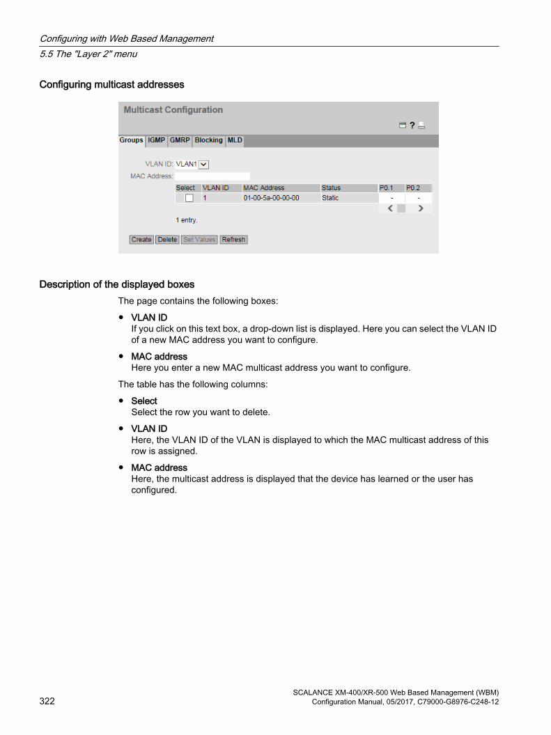
Configuring multicast addresses
Description of the displayed boxesThe page contains the following boxes:
● VLAN IDIf you click on this text box, a drop-down list is displayed. Here you can select the VLAN ID of a new MAC address you want to configure.
● MAC addressHere you enter a new MAC multicast address you want to configure.
The table has the following columns:
● SelectSelect the row you want to delete.
● VLAN IDHere, the VLAN ID of the VLAN is displayed to which the MAC multicast address of this row is assigned.
● MAC addressHere, the multicast address is displayed that the device has learned or the user has configured.
Configuring with Web Based Management5.5 The "Layer 2" menu
SCALANCE XM-400/XR-500 Web Based Management (WBM)322 Configuration Manual, 05/2017, C79000-G8976-C248-12

● Status - staticShows the status of each address entry. The address was entered statically by the user. Static addresses are stored permanently; in other words, they are not deleted when the aging time expires or when the device is restarted. These must be deleted by the user.
● Port ListThere is a column for each slot. Within a column, the multicast group to which the port belongs is shown. The drop-down list provides the following options:
– M(Member) Multicast frames are sent via this port.
– R(Registered) Member of the multicast group, registration was by a GMRP frame.
– F(Forbidden) Not a member of the multicast group. Moreover, this address must not be an address learned dynamically with GMRP or IGMP/MLD.
– –Not a member of the multicast group. No multicast frames with the defined multicast MAC address are sent via this port.
Steps in configurationCreating a new entry
Note
You cannot create any static multicast entries if GMRP is enabled.
1. Select the required VLAN ID from the ""drop-down list.
2. Enter the MAC address in the "MAC address" input box.
3. Click the "Create" button. A new entry is generated in the table.
4. Assign the relevant ports to the MAC address.
5. Click the "Set Values" button.
Creating layer 2 multicast addresses with a script and GMRP
If you want to create several layer 2 multicast addresses using a script, GMRP must be disabled as long as the script is executing. Follow the steps outlined below:
1. If GMRP is enabled, disable it. You configure GMRP on the "Layer 2 > Multicast > GMRP" page.
2. Run the script.
3. Enable GMRP only after the script has completed and the layer 2 multicast addresses have been created.
Deleting an entry
1. Select the check box in the row to be deleted.
2. Click the "Delete" button.The row is deleted from the display and from the memory of the device.
Configuring with Web Based Management5.5 The "Layer 2" menu
SCALANCE XM-400/XR-500 Web Based Management (WBM)Configuration Manual, 05/2017, C79000-G8976-C248-12 323

5.5.17.2 IGMP snooping
FunctionIE switches support "IGMP snooping" and the IGMP querier function. If "IGMP snooping" is enabled, IGMP frames are evaluated and the multicast filter table is updated with this information. If "IGMP Querier is also enabled, IE switches also send IGMP queries that trigger responses from IGMP-compliant nodes.
IGMP Snooping Aging TimeIn this menu, you can configure the aging time for IGMP Configuration. When the time elapses, entries created by IGMP are deleted from the address table if they are not updated by a new IGMP frame.
This applies to all ports; a port-specific configuration is not possible.
IGMP Snooping Aging Time depending on the querierSCALANCE XR500 as IGMP querier
If a SCALANCE XR500 is used as an IGMP querier, the query interval is 125 seconds. For the "IGMP Snooping Aging Time", set at least 250 seconds.
Other IGMP queriers
If a different IGMP querier is used, the value of the "IGMP Snooping Aging Time" should be at least twice as long as the query interval.
Description of the displayed boxes
Configuring with Web Based Management5.5 The "Layer 2" menu
SCALANCE XM-400/XR-500 Web Based Management (WBM)324 Configuration Manual, 05/2017, C79000-G8976-C248-12

The page contains the following boxes:
● IGMP SnoopingEnable or disable IGMP snooping (Internet Group Management Protocol). The function activates IGMP snooping on all interfaces. if the function is enabled, the multicast addresses learned with IGMP snooping are entered in the multicast filter table.
● IGMP Snooping Aging Time [s]In this box, enter the value for the aging time in seconds. As default, 300 seconds is set.Range of values: 130 - 1225 seconds
● IGMP Querier Enable or disable "IGMP Querier". The device sends IGMP requests cyclocally.
Steps in configuration1. Select the "IGMP Snooping" check box.
2. Enter the value for the aging time in seconds in the "IGMP Snooping Aging Time" box.
3. Select the "IGMP Querier" check box.
4. Click the "Set Values" button.
5.5.17.3 GMRP
Activating GMRPOn this page, you specify whether or not GMRP is used for each individual port. If "GMRP" is disabled for a port, no registrations are made for it and it cannot send GMRP frames.
For GMRP to work, you need to enable the function globally and on the ports.
Configuring with Web Based Management5.5 The "Layer 2" menu
SCALANCE XM-400/XR-500 Web Based Management (WBM)Configuration Manual, 05/2017, C79000-G8976-C248-12 325
Description of the displayed boxesThe page contains the following box:
● GMRPEnable or disable the GMRP function.
Table 1 has the following columns:
● 1st columnShows that the settings are valid for all ports of table 2.
● SettingSelect the setting from the drop-down list. You have the following setting options:
– EnabledEnables the sending of GMRP frames.
– DisabledDisables the sending of GMRP frames.
– No changeTable 2 remains unchanged.
● Copy to tableIf you click the button, the settings are adopted for all ports of table 2.
Table 2 has the following columns:
● PortThis column shows all the ports available on the device as well as the link aggregations.
● SettingWith this check box, you enable or disable GMRP for the port or link aggregation.
Steps in configurationEnabling the sending of GMRP frames for an individual port
1. Select the "GMRP" check box.
2. Select the check box in the relevant row in table 2.
3. To apply the changes, click the "Set Values" button.
Enabling the sending of GMRP frames for all ports
1. Select the "GMRP" check box.
2. In the "Setting" drop-down list, select the "Enabled" entry.
3. Click the "Copy to table" button. The check box is enabled for all ports in table 2.
4. To apply the changes, click the "Set Values" button.
Configuring with Web Based Management5.5 The "Layer 2" menu
SCALANCE XM-400/XR-500 Web Based Management (WBM)326 Configuration Manual, 05/2017, C79000-G8976-C248-12

5.5.17.4 Multicast blocking
Disabling the forwarding of unknown multicast framesOn this page, you can block the forwarding of unknown multicast frames for individual ports.
Description of the displayed valuesTable 1 has the following columns:
● 1st columnShows that the settings are valid for all ports of table 2.
● SettingSelect the setting from the drop-down list. You have the following setting options:
– EnabledBlocking of multicast frames is enabled.
– DisabledBlocking of unknown multicast frames is disabled.
– No changeTable 2 remains unchanged.
● Copy to TableIf you click the button, the setting is adopted for all ports of table 2.
Table 2 has the following columns:
● PortAll available ports are listed in this column. Unavailable ports are not displayed.
● SettingEnable or disable the blocking of multicast frames.
Configuring with Web Based Management5.5 The "Layer 2" menu
SCALANCE XM-400/XR-500 Web Based Management (WBM)Configuration Manual, 05/2017, C79000-G8976-C248-12 327

Steps in configurationEnabling blocking for an individual port
1. Select the check box in the relevant row in table 2.
2. To apply the changes, click the "Set Values" button.
Enabling blocking for all ports
1. In the "Setting" drop-down list, select the "Enabled" entry.
2. Click the "Copy to table" button. The check box is enabled for all ports in table 2.
3. To apply the changes, click the "Set Values" button.
5.5.17.5 MLD (IPv6)
Mulitcast Listener DiscoveryDevices support "MLD snooping" and the "MLD querier" function. If "MLD snooping" is enabled, MLD frames are evaluated and the multicast filter table is updated with this information. If "IGMP querier is also enabled, IE switches also send MLD queries that trigger responses from MLD-compliant nodes.
With MLD snooping, MLD frames are only forwarded to the intended multicast listeners instead of being flooded to all ports.
For MLD snooping to work, you need to enable the function globally and in the VLANs.
MLD Snooping Aging TimeOn this page, you can configure the aging time for MLD configuration. When the time elapses, entries created by MLD are deleted from the address table if they are not updated by a new MLD packet.
This applies to all VLANS; a VLAN-specific configuration is not possible.
Configuring with Web Based Management5.5 The "Layer 2" menu
SCALANCE XM-400/XR-500 Web Based Management (WBM)328 Configuration Manual, 05/2017, C79000-G8976-C248-12

Description
The page contains the following:
● MLD SnoopingEnable or disable MLD on the device.
● MLD Snooping Aging TimeEnter the time after which entries generated by MLD are deleted from the multicast filter table. Assuming that this is not updated by a new MLD packet.This applies to all VLANS; a VLAN-specific configuration is not possible
Table 1 has the following columns:
● 1st columnShows that the settings are valid for all VLANs of table 2.
● Snooping / QuerierSelect the setting. You have the following setting options:
– EnabledThe function is enabled.
– DisabledThe function is disabled.
– No ChangeTable 2 remains unchanged.
● Copy to TableIf you click the button, the settings are adopted for all ports of table 2.
Configuring with Web Based Management5.5 The "Layer 2" menu
SCALANCE XM-400/XR-500 Web Based Management (WBM)Configuration Manual, 05/2017, C79000-G8976-C248-12 329

Table 2 has the following columns:
● VLAN IDShows the VLAN to which the settings relate
● SnoopingEnable or disable MLD for the required VLAN. When enabled, the MLD entries are included the multicast filter table and MLD packets are forwarded.
● QuerierEnable or disable "Querier". The device sends MLD queries.
Steps in configurationEnabling the sending of MLD frames for a VLAN
1. Select the "MLD Snooping" check box.
2. Select the check box in the relevant row in table 2.
3. To apply the changes, click the "Set Values" button.
Enabling the sending of MLD frames for all VLANs
1. Select the "MLD Snooping" check box.
2. Select the "enabled" entry in the "Snooping" and "Querier" drop-down lists.
3. Click the "Copy to table" button. The check box is enabled for all VLANs in table 2.
4. To apply the changes, click the "Set Values" button.
5.5.18 Broadcast
Blocking the forwarding of broadcast framesOn this page, you can block the forwarding of broadcast frames for individual ports.
Note
Some communication protocols work only with the support of broadcast. In these cases, blocking can lead to loss of data communication. Block broadcast only when you are sure that you do not need it.
Configuring with Web Based Management5.5 The "Layer 2" menu
SCALANCE XM-400/XR-500 Web Based Management (WBM)330 Configuration Manual, 05/2017, C79000-G8976-C248-12

Description of the displayed boxesTable 1 has the following columns:
● 1st columnShows that the settings are valid for all ports of table 2.
● SettingSelect the setting from the drop-down list. You have the following setting options:
– EnabledThe blocking of broadcast frames is enabled.
– DisabledThe blocking of broadcast frames is disabled.
– No changeTable 2 remains unchanged.
● Copy to Table If you click the button, the setting is adopted for all ports of table 2.
Table 2 has the following columns:
● PortAll available ports and the link aggregations are displayed.
● SettingEnable or disable the blocking of broadcast frames.
Steps in configurationEnabling the blocking of broadcast frames for an individual port
1. Select the check box in the relevant row in table 2.
2. To apply the changes, click the "Set Values" button.
Configuring with Web Based Management5.5 The "Layer 2" menu
SCALANCE XM-400/XR-500 Web Based Management (WBM)Configuration Manual, 05/2017, C79000-G8976-C248-12 331

Enabling the blocking of broadcast frames for all ports
1. In the "Setting" drop-down list, select the "Enabled" entry.
2. Click the "Copy to table" button. The check box is enabled for all ports in table 2.
3. To apply the changes, click the "Set Values" button.
5.5.19 PTP
5.5.19.1 GeneralThe following devices support time-of-day synchronization using PTP:
● SCALANCE XR528-6M
● SCALANCE XR552-12M
IEEE 1588 with SCALANCE devicesThe IEEE 1588v2 standard defines mechanisms with which highly precise time of day synchronization of devices in a network can be achieved. SCALANCE devices with suitable hardware support time synchronization according to IEEE 1588v2. The functionality is disabled on these devices when they are shipped and following a "Reset to factory default". To be able to use PTP, enable this function and configure every port that is on the synchronization path as well as ports that are blocked due to redundancy mechanisms. PTP can also be used with redundancy mechanisms in the ring such as HRP, standby linking of rings, MRP and RSTP. The following sections describe the configuration options of Web Based Management.
1588 ConfigurationOn this page, you specify how the device will process PTP messages.
Configuring with Web Based Management5.5 The "Layer 2" menu
SCALANCE XM-400/XR-500 Web Based Management (WBM)332 Configuration Manual, 05/2017, C79000-G8976-C248-12

1588 ModeYou can make the following settings:
● offThe device does not process any PTP messages. PTP messages are, however, forwarded according to the rules of the switch.
● transparentThe device adopts the function of a transparent clock and forwards PTP messages to other nodes while at the same time making entries in the correction field of the PTP message.
5.5.19.2 TC General
TC General
On this tab, you will find the general settings for PTP.
1588 Transparent Clock ConfigurationDelay MechanismSpecify the delay mechanism the device will work with:
● end to end(Delay request response mechanism will be used)
Note
With end-to-end synchronization with more than 2 slaves, freak values > 100 ns can occur in the offset.
● peer to peer(Peer delay mechanism will be used)
Domain NumberEnter the domain number for the device here. The device ignores PTP messages with a different domain number. A SCALANCE device can only be assigned to one synchronization domain.
Configuring with Web Based Management5.5 The "Layer 2" menu
SCALANCE XM-400/XR-500 Web Based Management (WBM)Configuration Manual, 05/2017, C79000-G8976-C248-12 333
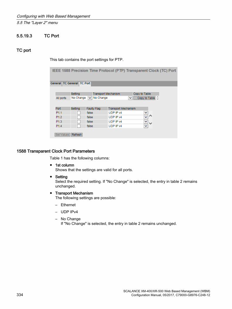
5.5.19.3 TC Port
TC port
This tab contains the port settings for PTP.
1588 Transparent Clock Port ParametersTable 1 has the following columns:
● 1st columnShows that the settings are valid for all ports.
● SettingSelect the required setting. If "No Change" is selected, the entry in table 2 remains unchanged.
● Transport MechanismThe following settings are possible:
– Ethernet
– UDP IPv4
– No ChangeIf "No Change" is selected, the entry in table 2 remains unchanged.
Configuring with Web Based Management5.5 The "Layer 2" menu
SCALANCE XM-400/XR-500 Web Based Management (WBM)334 Configuration Manual, 05/2017, C79000-G8976-C248-12

Table 2 shows detailed information about the individual ports:
● PortThe port number. With modular devices, the slot number and port number are displayed separated by a dot.PTP is not supported on SFP+ ports.
● SettingThe port status. The following entries are possible:
– disabledThe port is not involved in PTP.
– enabledThe port processes PTP messages.
● Faulty FlagThe error status relating to PTP.
– trueAn error occurred.
– falseNo error has occurred on this port.
● Transport mechanismChoose how this port will handle PTP message data traffic. You can make different settings for the ports of a device, however, the relevant communications partner must support the selected transport mechanism. The following settings are possible:
– Ethernet
– UDP IPv4
5.5.20 RMON
5.5.20.1 Statistics
Statistics On this page you can specify the ports for which RMON statistics are displayed.
The RMON statistics are shown on the page “Information > Ethernet Statistics” in “Packet Size”, “Frame Type” and “Packet Error” tabs.
Configuring with Web Based Management5.5 The "Layer 2" menu
SCALANCE XM-400/XR-500 Web Based Management (WBM)Configuration Manual, 05/2017, C79000-G8976-C248-12 335

Settings
● RMONIf you select this check box, Remote Monitoring (RMON) allows diagnostics data to be collected on the device, prepared and read out using SNMP by a network management station that also supports RMON. This diagnostic data, for example port-related load trends, allow problems in the network to be detected early and eliminated.
Note
If you disable RMON, these statistics are not deleted but retain their last status.
● PortSelect the ports for which statistics will be displayed.
The table has the following columns:
● SelectSelect the row you want to delete.
● PortShows the ports for which statistics will be displayed.
Steps in configurationEnabling the function
1.Select the "RMON" check box.
2.Click the "Set Values" button.The "RMON" function is enabled.
Configuring with Web Based Management5.5 The "Layer 2" menu
SCALANCE XM-400/XR-500 Web Based Management (WBM)336 Configuration Manual, 05/2017, C79000-G8976-C248-12
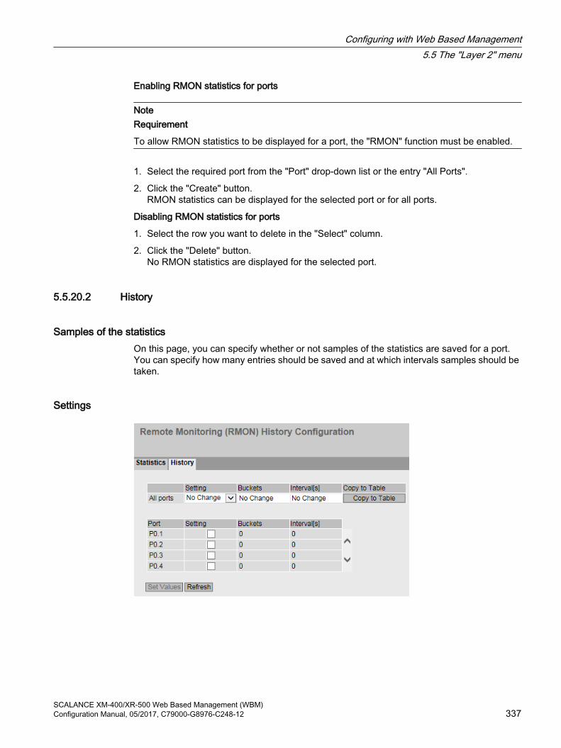
Enabling RMON statistics for ports
NoteRequirement
To allow RMON statistics to be displayed for a port, the "RMON" function must be enabled.
1. Select the required port from the "Port" drop-down list or the entry "All Ports".
2. Click the "Create" button.RMON statistics can be displayed for the selected port or for all ports.
Disabling RMON statistics for ports
1. Select the row you want to delete in the "Select" column.
2. Click the "Delete" button.No RMON statistics are displayed for the selected port.
5.5.20.2 History
Samples of the statistics On this page, you can specify whether or not samples of the statistics are saved for a port. You can specify how many entries should be saved and at which intervals samples should be taken.
Settings
Configuring with Web Based Management5.5 The "Layer 2" menu
SCALANCE XM-400/XR-500 Web Based Management (WBM)Configuration Manual, 05/2017, C79000-G8976-C248-12 337

Table 1 has the following columns:
● 1st columnShows that the settings are valid for all ports.
● SettingSelect the required setting. If "No Change" is selected, the entry in table 2 remains unchanged.
● EntriesEnter the maximum number of samples to be stored at the same time. If "No Change" is entered, the entry in table 2 remains unchanged
● Interval [s]Enter the interval after which the current status of the statistics will be saved as a sample. If "No Change" is entered, the entry in table 2 remains unchanged
● Copy to TableIf you click the button, the settings are adopted for all ports of table 2.
Table 2 has the following columns:
● PortShows the port to which the settings relate.
● SettingEnable or disable the recording of the history on the relevant port.
● EntriesEnter the maximum number of samples to be stored at the same time.The maximum number of entries can be restricted by the capacity of the device.Range of values: 1 - 65535Factory setting: 24
● Interval [s]Enter the interval after which the current status of the statistics will be saved as a sample.Range of values: 1 - 3600Factory setting: 3600
Steps in configurationEnabling RMON statistics for individual ports
1. Select the check box "Setting" in the relevant row in table 2.The "Entries" and "Interval[s]" boxes become active with the factory settings.
2. Enter the required values in the "Entries" and "Interval[s]" boxes.
3. Click the "Set Values" button.
Enabling RMON statistics for all ports
1. In the "Setting" drop-down list, select the "Enabled" entry in table 1.
2. Enter the required values in the "Entries" and "Interval[s]" boxes. If you do not change the entries in both boxes, the factory defaults will be used for all ports.
3. Click the "Copy to Table" button.The settings are adopted for all ports of table 2.
4. Click the "Set Values" button.
Configuring with Web Based Management5.5 The "Layer 2" menu
SCALANCE XM-400/XR-500 Web Based Management (WBM)338 Configuration Manual, 05/2017, C79000-G8976-C248-12

5.6 The "Layer 3 (IPv4)" menu
5.6.1 Configuration
IntroductionThe page contains the overview of the layer 3 functions for IPv4 of the device. On this page, you enable or disable the required layer 3 function.
Die functions "Routing", "VRRP", "OSPF", "RIP" and "PIM" are available only on layer 3.
Description of the displayed boxesThe page contains the following boxes:
● Routing (only available with devices with a layer 3 license)
– EnabledIPv4 routing is enabled. You can only enable the routing function if DHCP is disabled on all configured interfaces.
– DisabledIPv4 routing is disabled. If IPv6 routing is enabled, this is also disabled.
● DHCP Relay AgentEnable or disable the DHCP relay agent. You can configure other settings in "Layer 3 (IPv4)> DHCP Relay Agent".
● VRRP (only available with devices with a layer 3 license)Enable or disable routing using VRRP. To use VRRP, first enable the routing function. You can configure other settings in "Layer 3 (IPv4) > VRRP".
● OSPF (only available with devices with a layer 3 license)Enable or disable routing using OSPF. To use OSPF, first enable the "Routing" function. You can configure other settings in "Layer 3 (IPv4) > OSPF".
Configuring with Web Based Management5.6 The "Layer 3 (IPv4)" menu
SCALANCE XM-400/XR-500 Web Based Management (WBM)Configuration Manual, 05/2017, C79000-G8976-C248-12 339

● RIP (only available with devices with a layer 3 license)Enable or disable routing using RIP. To use RIP , first enable the routing function. You can configure other settings in "Layer 3 (IPv4) > RIP".
● PIM Routing (only available with devices with a layer 3 license)Enable or disable the PIM routing. You can configure other settings in "Layer 3 (IPv4) > PIM".
Steps in configuration1. To use the required function, select the corresponding check box.
2. Click the "Set Values" button.
5.6.2 Subnets
5.6.2.1 Overview
Creating subnetsThe page shows the subnets for the selected interface. If more than one subnet is available on an interface, the first entry of this interface is of the address type "Primary".
All other subnets are created on this page. A subnet always relates to an interface. The interface is created on the "Configuration" tab.
Description of the displayed valuesThe page contains the following boxes:
● InterfaceSelect the interface on which you want to configure another subnet.
Configuring with Web Based Management5.6 The "Layer 3 (IPv4)" menu
SCALANCE XM-400/XR-500 Web Based Management (WBM)340 Configuration Manual, 05/2017, C79000-G8976-C248-12

● LoopbackEnable or disable the "loopback" property on the interface.If the "loopback" property is to be enabled for an IP interface, the assigned VLAN must not contain any member ports.Since the IP interface is not linked to physical ports, the operating status of the IP interface is not dependent on the link status of the physical ports. The loopback interface can be reached as long as the device is connected to a suitable power supply.Via the loopback interface you can access the device.
Note
An interface configured as loopback must be located in its own subnet with a subnet mask of at least 30 bits.
The table has the following columns:
● SelectSelect the row you want to delete.
● InterfaceShows the interface.
● TIA InterfaceShows the selected TIA interface.
● Interface NameShows the name of the interface.
● MAC Address Shows the MAC address.
● IP AddressShows the IPv4 address of the subnet.
● Subnet MaskShows the subnet mask.
● Address TypeDisplays the address type. The following values are possible:
– PrimaryThe first IPv4 address that was configured on an IPv4 interface.
– SecondaryAll other IPv4 address that were configured on an IPv4 interface.
● IP Assgn MethodShows how the IPv4 address is assigned. The following values are possible:
– StaticThe IPv4 address is static. You enter the settings in "IP Address" and "Subnet Mask".
– Dynamic (DHCP)The device obtains a dynamic IPv4 address from a DHCPv4 server.
Configuring with Web Based Management5.6 The "Layer 3 (IPv4)" menu
SCALANCE XM-400/XR-500 Web Based Management (WBM)Configuration Manual, 05/2017, C79000-G8976-C248-12 341

● Address Collision Detection StatusIf new IPv4 addresses become active in the network, the "Address Collision Detection" function checks whether this can result in address collisions. The allows IPv4 addresses that would be assigned twice to be detected.
Note
The function does not run a cyclic check.
This column shows the current status of the function. The following values are possible:
– IdleThe interface is not enabled and does not have an IPv4 address.
– StartingThis status indicates the start-up phase. In this phase, the device initially sends a query as to whether the planned IPv4 address already exists. If the address is not yet been assigned, the device sends the message that it is using this IP address as of now.
– ConflictThe interface is not enabled. The interface is attempting to use an IPv4 address address that has already been assigned.
– DefendingThe interface uses a unique IPv4 address. Another interface is attempting to use the same IPv4 address.
– ActiveThe interface uses a unique IPv4 address. There are no collisions.
– Not supportedThe function for detection of address collisions is not supported.
– DisabledThe function for detection of address collisions is disabled.
● LoopbackShows whether or not the "loopback" property is enabled.
Steps in configuration1. Select the interface from the "Interface" drop-down list.
2. If appropriate select the "loopback" property.
3. Click the "Create" button. A new row is inserted in the table.
4. Click the "Set Values" button. Configure the subnet on the "Configuration" tab.
Configuring with Web Based Management5.6 The "Layer 3 (IPv4)" menu
SCALANCE XM-400/XR-500 Web Based Management (WBM)342 Configuration Manual, 05/2017, C79000-G8976-C248-12

5.6.2.2 ConfigurationOn this page, you configure the IPv4 interface.
Description of the displayed valuesThe page contains the following boxes:
● Interface (name)Select the interface from the drop-down list.
● Interface NameEnter the name of the interface.
● MAC AddressDisplays the MAC address of the selected interface.
● DHCPEnable or disable the DHCP client for this IPv4 interface.
Note
If you want to operate the device as a router with several interfaces, disable DHCP on all interfaces.
● IP AddressEnter the IPv4 address of the interface. The IPv4 addresses must not be used more than once.
● Subnet MaskEnter the subnet mask of the subnet you are creating. Subnets on different interfaces must not overlap.
Configuring with Web Based Management5.6 The "Layer 3 (IPv4)" menu
SCALANCE XM-400/XR-500 Web Based Management (WBM)Configuration Manual, 05/2017, C79000-G8976-C248-12 343

● Address TypeShows the address type. The following values are possible:
– PrimaryThe first subnet of the interface.
– SecondaryAll further subnets of the interface.
● LoopbackShows whether or not the "loopback" property is enabled.
● TIA InterfaceSelect whether or not this interface should become the TIA Interface.
Steps in configuration1. Select the interface from the "Interface (name)" drop-down list.
2. Enter a name for the Interface in "Interface Name".
3. Enter the IPv4 address of the subnet in the "IP Address" column.
4. Enter the subnet mask belonging to the IPv4 address in the "Subnet Mask" column
5. Click the "Set Values" button.
Configuring with Web Based Management5.6 The "Layer 3 (IPv4)" menu
SCALANCE XM-400/XR-500 Web Based Management (WBM)344 Configuration Manual, 05/2017, C79000-G8976-C248-12

5.6.3 NAT
5.6.3.1 NATOn this WBM page, you specify the basic settings for NAT.
DescriptionThe page contains the following boxes:
● NATEnable or disable NAT/NAPT for the entire device. When enabled, the device operates as a NAT router.
● Idle Timeout [s]Enter the required time. The device checks cyclically after the set period has elapsed whether the aging time of TCP and UDP connections has elapsed. The connections whose aging time has elapsed since the last check are deleted from the table "NAT Translations".
● TCP Timeout [s]Enter the required aging time for TCP connections. TCP connections are stored until no data exchange has taken place for the set period. Depending on the cyclic check when the Idle Timeout has elapsed, the connections are deleted from the table "NAT translations".
● UDP Timeout [s]Enter the required aging time for UDP connections. UDP connections are stored until no data exchange has taken place for the set period. Depending on the cyclic check when the Idle Timeout has elapsed, the connections are deleted from the table "NAT translations".
Configuring with Web Based Management5.6 The "Layer 3 (IPv4)" menu
SCALANCE XM-400/XR-500 Web Based Management (WBM)Configuration Manual, 05/2017, C79000-G8976-C248-12 345
● InterfaceSelect an IP interface from the drop-down list on which you want to configure NAT.As soon as you have configured an interface as a NAT interface, all other configurations are considered starting from this interface. This means for this interface that all networks reachable via the interface itself count as "Outside". All other networks are "Inside".
Note
If you have configured several NAT interfaces on a device, this means that a network is "Outside" from the perspective of one NAT interface and "Inside" from the perspective of another NAT interface.
● NATEnable or disable NAT for an IP interface.An entry is created automatically in the "Pool" tab. The device can be reached from the external network using the IP address of the IP interface.If you disable NAT for an IP interface and there are no configurations on the NAT interface, the entry is automatically deleted from the table.
● NAPTEnable or disable NAPT for an IP interface.
The table has the following columns:
● InterfaceInterface on which there is a NAT configuration.
● NATShows whether NAT is enabled or disabled for the selected IP interface.NAT is only enabled, when you have enabled NAT for the entire device.
● NAPTShows whether NAPT is enabled or disabled for the selected IP interface.NAPT is only enabled, when you have enabled NAT for the entire device.If you do not create any further configurations for NAPT, the dynamic port translation is enabled automatically. As default, a device in the internal network cannot be reached from an external network. If the internal device wants to communicate in an external network, the inside local address and the IP address of the IP interface have a port added and the internal device is assigned as inside local and inside global address. Using this inside global address, the internal device can be reached from the external network until the timer of the connection elapses.
ProcedureTo configure NAT/NAPT proceed as follows:
1. Enter the required times.
2. Select the required IP interface.
3. Enable NAT/NAPT for the selected IP interface.
4. Click the "Set Values" button.
5. Make the settings you require for NAT/NAPT in the NAT/NAPT tabs.
Configuring with Web Based Management5.6 The "Layer 3 (IPv4)" menu
SCALANCE XM-400/XR-500 Web Based Management (WBM)346 Configuration Manual, 05/2017, C79000-G8976-C248-12

6. Select the "NAT" check box on this tab.
7. Click the "Set Values" button.
5.6.3.2 StaticOn this WBM page, you configure static 1:1 address translations.
You specify which inside global address the inside local address of a device will be converted to and vice versa. This variant allows connection establishment in both directions. The device in the internal network can be reached from the external network.
DescriptionThe page contains the following boxes:
● InterfaceSelect the a NAT interface from the drop-down list for which you want to create further NAT configurations.
● Inside Local AddressEnter the actual address of the device that should be reachable from external.
● Inside Global AddressEnter the address at which the device can be reached from external.
The table has the following columns:
● 1st columnSelect the check box in the row to be deleted.
● InterfaceNAT interface to which the setting relates.
● Inside Local AddressShows the actual address of the device that should be reachable from external.
● Inside Global AddressShows the address at which the device can be reached from external.
Configuring with Web Based Management5.6 The "Layer 3 (IPv4)" menu
SCALANCE XM-400/XR-500 Web Based Management (WBM)Configuration Manual, 05/2017, C79000-G8976-C248-12 347

ProcedureTo create a 1:1 address translation, proceed as follows:
1. Select the a NAT interface from the "Interface" drop-down list:
2. In "Inside Local Address" enter the actual address of the device that should be reachable from external.
3. In "Inside Global Address" enter the address at which the device can be reached from external.
5.6.3.3 PoolOn this WBM page, you configure dynamic address translations.
As default, a device in the internal network cannot be reached from an external network. If the internal device wants to communicate in an external network, an inside global address is assigned to it dynamically. Using this inside global address, the internal device can be reached from the external network until the timer of the connection elapses.
DescriptionThe page contains the following boxes:
● InterfaceSelect the a NAT interface from the drop-down list for which you want to create further NAT configurations.
● Inside Global AddressEnter the start address for the dynamic assignment of addresses at which devices will be reachable from external.
● Inside Local Address MaskEnter the address mask of the external subnet.
Configuring with Web Based Management5.6 The "Layer 3 (IPv4)" menu
SCALANCE XM-400/XR-500 Web Based Management (WBM)348 Configuration Manual, 05/2017, C79000-G8976-C248-12

The table has the following columns:
● 1st columnSelect the check box in the row to be deleted.
● InterfaceNAT interface to which the setting relates.
● Inside Global AddressShows the start address for the dynamic assignment of addresses at which devices will be reachable from external.
● Inside Local Address MaskShows the address mask of the external subnet.
ProcedureTo create a dynamic address translation, proceed as follows:
1. Select the a NAT interface from the "Interface" drop-down list:
2. In "Inside Global Address" enter the start address for the dynamic assignment of addresses at which devices will be reachable from external.
3. In "Inside Global Address Mask" enter the address mask of the external subnet.
5.6.3.4 NAPTOn this WBM page, you configure static port translations.
Configuring with Web Based Management5.6 The "Layer 3 (IPv4)" menu
SCALANCE XM-400/XR-500 Web Based Management (WBM)Configuration Manual, 05/2017, C79000-G8976-C248-12 349

Description The page contains the following boxes:
● InterfaceSelect the a NAT interface from the drop-down list for which you want to create further NAT configurations.
● Inside Local AddressEnter the actual address of the device that should be reachable from external.
● ServiceSelect the service for which the port translation is valid.When you select a service, the same port is entered in the Start Port and End Port boxes. If you change the start port, the end port is changed accordingly.if you select the entry "-", you can enter the start and end port freely.
● Start PortEnter an inside local port.
● End PortDepending on your selection in the "Service" drop down list, you can enter a inside local port or a port is displayed.If you enter different ports in the Start Port and End Port boxes, the same port range is entered in the Inside Global Port box. A port range can only be translated to the same port range.If you enter the same port in the Start Port and End Port boxes, you can enter any Inside Global Port.
● Inside Global PortDepending on your selection in the "Service" drop down list, you can enter a port or a port is displayed.
● ProtocolSelect the protocol for which the port translation is valid.
● DescriptionEnter a description for the port translation.
The table has the following columns:
● 1st columnSelect the check box in the row to be deleted.
● InterfaceNAT interface to which the setting relates.
● Inside Local AddressShows the actual address of the device that should be reachable from external.
● Start PortShows the start port that will be assigned to the inside local address.
● End PortShows the end port that will be assigned to the inside local address.
● ProtocolShows the protocol for which the port translation is valid.
● Inside Global AddressShows the address at which the device can be reached from external.
Configuring with Web Based Management5.6 The "Layer 3 (IPv4)" menu
SCALANCE XM-400/XR-500 Web Based Management (WBM)350 Configuration Manual, 05/2017, C79000-G8976-C248-12

● Inside Global PortShows the port that will be assigned to the Inside Global Address.
● DescriptionShows a a description for the port translation.
ProcedureTo create a static port translation, proceed as follows:
1. Select the a NAT interface from the "Interface" drop-down list:
2. In "Inside Local Address" enter the actual address of the device that should be reachable from external.
3. Select a service.
4. Depending on your selection in the "Service" drop-down list specify the start, end and inside global port.
5. Select a protocol.
6. Enter a description for the port translation.
5.6.4 Static Routes
Static routeOn this page, you create the static IPv4 routes.
Description of the displayed valuesThe page contains the following boxes:
● Destination NetworkEnter the network address of the destination that can be reached via this route.
● Subnet MaskEnter the corresponding subnet mask.
Configuring with Web Based Management5.6 The "Layer 3 (IPv4)" menu
SCALANCE XM-400/XR-500 Web Based Management (WBM)Configuration Manual, 05/2017, C79000-G8976-C248-12 351

● GatewayEnter the IPv4 address of the gateway via which this network address is reachable.
● Administrative DistanceEnter the administrative distance for the route. The administrative distance corresponds to the quality of a connection, based for example on speed or costs. If there are several equal routes, the route with the lowest value is used.As default -1 is set. This setting means that the metric is not set.Range of values: 1 - 254
The table has the following columns:
● SelectSelect the row you want to delete.
● Destination NetworkShows the network address of the destination.
● Subnet MaskShows the corresponding subnet mask.
● GatewayShows the IPv4 address of the next gateway.
● InterfaceShows the interface of the route.
● Administrative DistanceEnter the administrative distance for the route. When creating the route, "not used" is entered automatically (value -1). The administrative distance corresponds to the quality of a connection, based for example on speed or costs. If there are several equal routes, the route with the lowest value is used.Range of values: 1 - 254
● StatusShows whether or not the route is active.
Steps in configuration1. Enter the network address of the destination in the "Destination Network" input box.
2. Enter the corresponding subnet mask in the "Subnet Mask" input box.
3. Enter the gateway in the "Gateway" input box.
4. Enter the weighting of the route in "Administrative Distance".
5. Click the "Create" button. A new entry is generated in the table.
6. Click the "Set Values" button.
Configuring with Web Based Management5.6 The "Layer 3 (IPv4)" menu
SCALANCE XM-400/XR-500 Web Based Management (WBM)352 Configuration Manual, 05/2017, C79000-G8976-C248-12

5.6.5 Route Maps
5.6.5.1 General
Route mapsWith route maps, you control how routing information is further processed. You can filter routing information and specify whether the information is further processed, modified or discarded.
Route maps operate according to the following principle:
● Routing information is compared with the filters of the route maps.
● The comparison is continued until the filters of a route map match the properties of an item of information.
● The information is then processed according to the route map settings:
– The routing information is discarded.
– The properties of the routing information are changed.
Settings
Figure 5-10 Route maps general
● NameEnter the name for the route map.
● Sequence NumberEnter a number for the route map.You can create several route maps with the same name but with different sequence numbers. The sequence numbers then specify the order in which the route maps are processed.
Configuring with Web Based Management5.6 The "Layer 3 (IPv4)" menu
SCALANCE XM-400/XR-500 Web Based Management (WBM)Configuration Manual, 05/2017, C79000-G8976-C248-12 353

The table has the following columns:
● SelectSelect the row you want to delete.
● NameShows the name of the route map.
● Sequence NumberShows the sequence number of the route map.
● ActionSpecify what happens to the routing information that matches the settings of the route map:
– permitThe routing information is further processed according to the settings you make in the "Set" tab.
– denyThe routing information is discarded.
5.6.5.2 Interface & Value MatchOn this page, you specify whether or not the routing information for a route map is filtered according to interfaces, metric or tags.
Settings
Figure 5-11 Filtering route maps and metric
Configuring with Web Based Management5.6 The "Layer 3 (IPv4)" menu
SCALANCE XM-400/XR-500 Web Based Management (WBM)354 Configuration Manual, 05/2017, C79000-G8976-C248-12

● Route Map (Name/Seq. No.)Select a route map.The created route maps are available to you.
● TypeSelect the basis for the filtering:
– Interface
– Metric
– Tag
– Route Type
– metric type
● InterfaceSelect an interface.This box is active only if you have selected the "Interface" entry in the "Type" drop-down list.
● MetricEnter a value for the metric.This box is active only if you have selected the "Metric" entry in the "Type" drop-down list.
● TagEnter a value for the tag.This box is active only if you have selected the entry "Tag in the "Type" drop-down list.
Configuring with Web Based Management5.6 The "Layer 3 (IPv4)" menu
SCALANCE XM-400/XR-500 Web Based Management (WBM)Configuration Manual, 05/2017, C79000-G8976-C248-12 355

● Route TypeSelect the type of the route.
– LocalThe routing information for the route map is filtered according to directly connected routes (local interfaces).
– RemoteThe routing information for the route map is filtered according to learned or statically configured routes.
This box is active only if you have selected the entry "Route Type in the "Type" drop-down list.
● metric typeSelect the type of the metric.
– inter-areaThe routing information for the route map is filtered according to routes learned from other areas.
– intra-areaThe routing information for the route map is filtered according to routes originating from the same area.
– type-1-externalThe routing information for the route map is filtered according to routes whose path costs (metric) are made up of the external path costs and the path costs to the ASBR.
– type-2-externalThe routing information for the route map is filtered according to routes with only external path costs (netric).
This box is active only if you have selected the entry "Metric Type" in the "Type" drop-down list.
The table has the following columns:
● SelectSelect the row you want to delete.
● TypeShows the selected type:
– Interface
– Metric
– Tag
– Route Type
– metric type
● ValueShows the selected interface or the value of the metric or of the tag.
5.6.5.3 Destination MatchOn this page, you specify whether or not the routing information for a route map is filtered based on the destination IPv4 address.
Configuring with Web Based Management5.6 The "Layer 3 (IPv4)" menu
SCALANCE XM-400/XR-500 Web Based Management (WBM)356 Configuration Manual, 05/2017, C79000-G8976-C248-12

Settings
Figure 5-12 Route Maps Destination Match
● Route Map (Name/Seq. No.)Select a route map.
● IP AddressEnter the IPv4 address of the destination on which the filtering is based.
● Subnet MaskEnter the subnet mask of the destination on which the filtering is based.
The table has the following columns:
● SelectSelect the row you want to delete.
● IP AddressShows the IPv4 address of the destination.
● Subnet MaskShows the subnet mask of the destination.
5.6.5.4 Next Hop MatchOn this page, you specify whether or not the filtering for a route map will be based on the router to which the routing information is sent next.
Configuring with Web Based Management5.6 The "Layer 3 (IPv4)" menu
SCALANCE XM-400/XR-500 Web Based Management (WBM)Configuration Manual, 05/2017, C79000-G8976-C248-12 357

Settings
Figure 5-13 Route Maps Next Hop Match
● Route Map (Name/Seq. No.)Select a route map.
● IP AddressEnter the IP address of the router to which the routing information will be sent next.
The table has the following columns:
● SelectSelect the row you want to delete.
● IP AddressShows the IP address of the next router.
5.6.5.5 CreateOn this page, you specify whether or not the routing information will be changed by a route map.
You can only change the information of a "Permit" route map.
If, for example, you have filtered based on a certain metric, you can change the value of the metric here. The routing information is then forwarded with the new value.
Configuring with Web Based Management5.6 The "Layer 3 (IPv4)" menu
SCALANCE XM-400/XR-500 Web Based Management (WBM)358 Configuration Manual, 05/2017, C79000-G8976-C248-12

Settings
Figure 5-14 Route maps set
● Route Map (Name/Seq. No.)Select a route map.
The table has the following columns:
● SelectSelect the row you want to delete.
● NameShows the name of the route map.
● Sequence NumberShows the sequence number of the route map.
● MetricEnter the new value for the metric with which the routing information will be forwarded.
● TagEnter the new value for the tag with which the routing information will be forwarded.
5.6.6 DHCP Relay Agent
5.6.6.1 General
DHCP Relay Agent If the DHCP server is in a different network than the DHCP client, the client cannot reach the server. The DHCP relay agent intercedes between the DHCP server and DHCP client.
If you configure option 82, the DHCP relay agent expands the packets to the DHCP server by a circuit ID and a remote ID.
You can specify up to 4 DHCP servers for the DHCP relay agent. If a DHCP server is unreachable, the device can switch to a different DHCP server.
Configuring with Web Based Management5.6 The "Layer 3 (IPv4)" menu
SCALANCE XM-400/XR-500 Web Based Management (WBM)Configuration Manual, 05/2017, C79000-G8976-C248-12 359
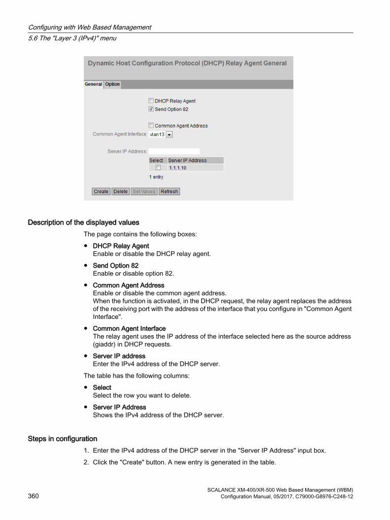
Description of the displayed valuesThe page contains the following boxes:
● DHCP Relay AgentEnable or disable the DHCP relay agent.
● Send Option 82Enable or disable option 82.
● Common Agent AddressEnable or disable the common agent address.When the function is activated, in the DHCP request, the relay agent replaces the address of the receiving port with the address of the interface that you configure in "Common Agent Interface".
● Common Agent InterfaceThe relay agent uses the IP address of the interface selected here as the source address (giaddr) in DHCP requests.
● Server IP addressEnter the IPv4 address of the DHCP server.
The table has the following columns:
● SelectSelect the row you want to delete.
● Server IP AddressShows the IPv4 address of the DHCP server.
Steps in configuration1. Enter the IPv4 address of the DHCP server in the "Server IP Address" input box.
2. Click the "Create" button. A new entry is generated in the table.
Configuring with Web Based Management5.6 The "Layer 3 (IPv4)" menu
SCALANCE XM-400/XR-500 Web Based Management (WBM)360 Configuration Manual, 05/2017, C79000-G8976-C248-12

3. Select the "DHCP Relay Agent" check box.
4. Select the "Send Option 82" check box.
5. Click the "Set Values" button.
5.6.6.2 Option
Parameters of the DHCP relay agentOn this page, you can specify parameters for the DHCP server, for example the circuit ID.The circuit ID describes the origin of the DHCP query, for example which port received the DHCP query.
You specify the DHCP server on the "General" tab.
Description of the displayed valuesThe page contains the following boxes:
Global configuration
● Circuit ID router index
Enable or disable the check box. If you enable the check box, the router-Index is added to the generated circuit ID.
● Circuit ID Receive VLAN IDEnable or disable the check box. If you enable the check box, the VLAN ID is added to the generated circuit ID.
Configuring with Web Based Management5.6 The "Layer 3 (IPv4)" menu
SCALANCE XM-400/XR-500 Web Based Management (WBM)Configuration Manual, 05/2017, C79000-G8976-C248-12 361

● Circuit ID Receive PortEnable or disable the check box. If you enable the check box, the receiving port is added to the generated circuit ID.
Note
You need to select a least one option.
You will find further information on the router index (Circuit ID Router Index) and port index (Circuit ID Receive Port) in the IfTable using SNMP.
You will find the VLAN ID on the WBM page "Layer 2 > VLAN > General".
● Remote IDShows the device ID.
Interface-specific configuration
● InterfaceSelect the interface from the drop-down list.
The table has the following columns:
● SelectSelect the row you want to delete.
● InterfaceShows the interface.
Note
If you have not created an interface-specific configuration, the global configuration with the MAC address is used as the device ID.
● Remote ID TypeSelect the type of device ID from the drop-down list. You have the following options:
– IP AddressThe IPv4 address of the device is used as the device ID.
– MAC AddressThe MAC address of the device is used as the device ID.
– Free TextIf you use "Free Text", you can enter the device name as the device identifier in "Remote ID".
● Remote IDEnter the device name. The box can only be edited if you select the entry "Free Text" for "Remote ID Type".
Configuring with Web Based Management5.6 The "Layer 3 (IPv4)" menu
SCALANCE XM-400/XR-500 Web Based Management (WBM)362 Configuration Manual, 05/2017, C79000-G8976-C248-12

● Circuit ID TypeSelect the type of circuit ID from the drop-down list. You have the following options:
– PredefinedThe circuit ID is created automatically based on the router index, VLAN ID or port.
– Free NumberIf you use "Free Number", you can enter the ID for "Circuit ID".
● Circuit IDEnter the circuit ID. The box can only be edited if you select the "Free Number" entry for the "Circuit ID Type".
Steps in configuration
Automatic assignment of the parametersFollow the steps below to specify automatic assignment of the parameters:
1. Enable the required option in "Global configuration".
– Circuit ID Router Index
– Circuit ID Receive VLAN ID
– Circuit ID Receive Port
2. Click the "Set Values" button.
Manual configuration of the parametersFollow the steps below to specify the parameters manually:
1. Enable the required option in "Global configuration".
– Circuit ID Router Index
– Circuit ID Receive VLAN ID
– Circuit ID Receive Port
2. Click the "Set Values" button.
3. Select the interface from the "Interface" drop-down list.
4. Click the "Create" button. A new row is inserted in the table.
5. Select the required entry from the "Remote ID Type" drop-down list.
– IP addressThe IPv4 address is used as the device ID.
– MAC addressThe MAC address is used as the device ID.
– Free TextEnter the device ID in "Remote ID".
Configuring with Web Based Management5.6 The "Layer 3 (IPv4)" menu
SCALANCE XM-400/XR-500 Web Based Management (WBM)Configuration Manual, 05/2017, C79000-G8976-C248-12 363

6. Select the required entry from the "Circuit ID Type" drop-down list.
– PredefinedThe router index is added to the generated Circuit ID.
– Free NumberEnter the ID in "Circuit ID".
7. Click the "Set Values" button.
5.6.7 VRRP
5.6.7.1 Router
Introduction Using the "Create" button, you can create new virtual routers. A maximum of 52 Virtual routers can be configured. You can configure other parameters on the "Configuration" tab.
Note● This function is available only with layer 3.● Select the "VRRP" check box to configure VRRP.● Simultaneous operation of VRRP and VRRPv3 is not possible.● You can only use VRRP in conjunction with VLAN interfaces. Router ports are not
supported.
Configuring with Web Based Management5.6 The "Layer 3 (IPv4)" menu
SCALANCE XM-400/XR-500 Web Based Management (WBM)364 Configuration Manual, 05/2017, C79000-G8976-C248-12

Description of the displayed valuesThe page contains the following boxes:
● VRRPEnable or disable routing using VRRP.
● Reply to pings on virtual interfacesWhen enabled, the virtual IPv4 addresses also reply to the ping.
● VRID-TrackingEnable or disable VRID tracking.When enabled, all VRRP instances are monitored. If the status of a VRRP instance changes to "Initialize", the priority of all VRRP instances is reduced to the value "1".If the status of a VRRP instance changes, the original priority of all VRRP instances is restored.
● InterfaceSelect the VLAN Interface that functions as the virtual router from the drop-down list.
● VRIDEnter the ID of the virtual router in the input box. This ID defines the group of routers that form a virtual router (VR). In the group, this is the same. It can no longer be used for other groups.Valid values are 1.. 255.
The table has the following columns:
● SelectSelect the row you want to delete.
● InterfaceShows the Interface that functions as the virtual router.
● VRID Shows the ID of the virtual router.
● Virtual MAC AddressShows the virtual MAC address of the virtual router.
● Primary IP AddressShows the numerically lowest IPv4 address in this VLAN. The entry 0.0.0.0 means that the "Primary" address on this VLAN is used. Otherwise all IPv4 addresses configured on this VLAN in the "Layer 3 (IPv4) > Subnets" menu are valid values.
● Router State Shows the current status of the virtual router. Possible values are:
– Master The router is the Master router and handles the routing functionality for all assigned IP addresses.
– BackupThe router is the backup router. If the master router fails, the backup router takes over the tasks of the master router.
– Initialize The virtual router has just been turned on. It will soon change to the "Master" or "Backup" state.
Configuring with Web Based Management5.6 The "Layer 3 (IPv4)" menu
SCALANCE XM-400/XR-500 Web Based Management (WBM)Configuration Manual, 05/2017, C79000-G8976-C248-12 365

● Master IP AddressShows the IPv4 address of the master router.
● PriorityShows the priority of the virtual router. Valid values are 1-254. If an IPv4 address is assigned to the VRRP router that is also actually configured on the local IPv4 interface, the value 255 is entered automatically. All other priorities can be distributed freely among the VRRP routers. The higher the priority, the earlier the VRRP router becomes "Master".
● Advert. Interval Shows the interval at which the master router sends VRRP packets.
● Preempt Shows the precedence of a router when changing roles between backup and master.
– yesThis router has precedence when changing roles.
– noThis router does not have precedence when changing roles.
VRRP and DHCP serverIf you want to operate a DHCP server on the devices of a VRRP group, the DHCP server must be configured on the master router. Backup routers do not react to DHCP queries. Make sure that the master router is statically configured and that after a failure, becomes the master of the VRRP group again.
Steps in configuration1. Select the "VRRP" check box.
2. Select the required interface.
3. Enter the ID of the virtual router in the "VRID" input box.
4. Click the "Create" button. A new row is inserted in the table.
5. Select the "Reply to pings on virtual interfaces" check box so that virtual addresses reply to pings as well.
6. Select the "VRID Tracking" check box to monitor the VRID.
7. Click the "Set Values" button. To configure the virtual router, click on the "Configuration" tab.
Configuring with Web Based Management5.6 The "Layer 3 (IPv4)" menu
SCALANCE XM-400/XR-500 Web Based Management (WBM)366 Configuration Manual, 05/2017, C79000-G8976-C248-12

5.6.7.2 Configuration
IntroductionOn this page, you configure the virtual router.
Note
This function is available only with layer 3.
Description of the displayed valuesThe page contains the following boxes:
● Interface / VRIDSelect the ID of the virtual router you are configuring from the drop-down list.
● Primary IP AddressSelect the numerically lowest IPv4 address from the drop-down list: If the router becomes master router, the router uses this IPv4 address.
Note
If you only configure one subnet on this VLAN, no entry is necessary. The entry is then 0.0.0.0. If you configure more than one subnet on the VLAN and you want a specific IPv4 address to be used as the source address for VRRP packets, select the IPv4 address from the drop-down list. Otherwise, the numerically lowest IPv4 address will be used.
Configuring with Web Based Management5.6 The "Layer 3 (IPv4)" menu
SCALANCE XM-400/XR-500 Web Based Management (WBM)Configuration Manual, 05/2017, C79000-G8976-C248-12 367
● MasterIf this option is enabled, the numerically lowest IPv4 address is entered for "Associated IP Address". This means that the highest priority IPv4 address of the VRRP router is used as the virtual IPv4 address of the virtual master router. The option must be disabled for the backup routers in this group and the IP address of the router in "Associated IP address" must be used.
● PriorityEnter the priority of this virtual router. Valid values are 1-255. If an IPv4 address is assigned to the VRRP router that is also actually configured on the local IPv4 interface, the value 255 is entered automatically. All other priorities can be distributed freely among the VRRP routers. The higher the priority, the earlier the VRRP router becomes "Master".
● Advertisement IntervalEnter the interval in seconds after which a master router sends a VRRP packet again.
● Preempt lower priority MasterAllow the precedence when changing roles between backup and master based on the selection process.
● Track IDSelect a track ID.
● Decrement PriorityEnter the value by which the priority of the VRRP interface will be reduced.
● Current PriorityShows the priority of the VRRP interface after the monitored interface has changed to the "down" status.
Steps in configurationTo configure a virtual router as the master router, follow the steps below:
1. Select the ID of the virtual router you want to configure from the "Interface / VRID" drop-down list.
2. Select the source address from the "Primary IP Address" drop-down list.
3. Select the "Master" check box.
4. From the "Priority" drop-down list, enter the priority of this virtual router.
5. Enter the interval in "Advertisement Interval".
6. Select the "Preempt lower priority Master" check box.
7. Select a track ID.
8. Value by which the priority of the VRRP interface will be reduced
9. Click the "Set Values" button.
Configuring with Web Based Management5.6 The "Layer 3 (IPv4)" menu
SCALANCE XM-400/XR-500 Web Based Management (WBM)368 Configuration Manual, 05/2017, C79000-G8976-C248-12
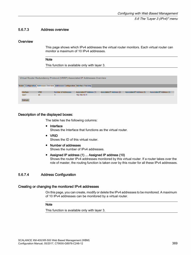
5.6.7.3 Address overview
OverviewThis page shows which IPv4 addresses the virtual router monitors. Each virtual router can monitor a maximum of 10 IPv4 addresses.
Note
This function is available only with layer 3.
Description of the displayed boxes:The table has the following columns:
● InterfaceShows the Interface that functions as the virtual router.
● VRIDShows the ID of this virtual router.
● Number of addressesShows the number of IPv4 addresses.
● Assigned IP address (1) ... Assigned IP address (10) Shows the router IPv4 addresses monitored by this virtual router. If a router takes over the role of master, the routing function is taken over by this router for all these IPv4 addresses.
5.6.7.4 Address Configuration
Creating or changing the monitored IPv4 addressesOn this page, you can create, modify or delete the IPv4 addresses to be monitored. A maximum of 10 IPv4 addresses can be monitored by a virtual router.
Note
This function is available only with layer 3.
Configuring with Web Based Management5.6 The "Layer 3 (IPv4)" menu
SCALANCE XM-400/XR-500 Web Based Management (WBM)Configuration Manual, 05/2017, C79000-G8976-C248-12 369

Description of the displayed valuesThe page contains the following boxes:
● Interface / VRIDSelect the virtual router from the drop-down list.
● Associated IP addressEnter the IPv4 address that the virtual router will monitor. A maximum of 10 IPv4 addresses are possible.
The table has the following columns:
● SelectSelect the row you want to delete.
● Associated IP AddressShows the IPv4 addresses that the virtual router monitors.
Steps in configuration1. Select the ID of the virtual router from the "Interface / VRID" drop-down list.
2. Enter the IPv4 address that the virtual router will monitor.
3. Click the "Create" button. A new entry is generated in the table.
5.6.7.5 Interface Tracking
IntroductionOn this page, you configure the monitoring of interfaces.
When the link of a monitored interface changes from "up" to "down", the priority of the assigned VRRP interface is reduced. You configure the value by which the priority is reduced on the page "Layer 3 > VRRP/VRRPv3 > Configuration".
Configuring with Web Based Management5.6 The "Layer 3 (IPv4)" menu
SCALANCE XM-400/XR-500 Web Based Management (WBM)370 Configuration Manual, 05/2017, C79000-G8976-C248-12
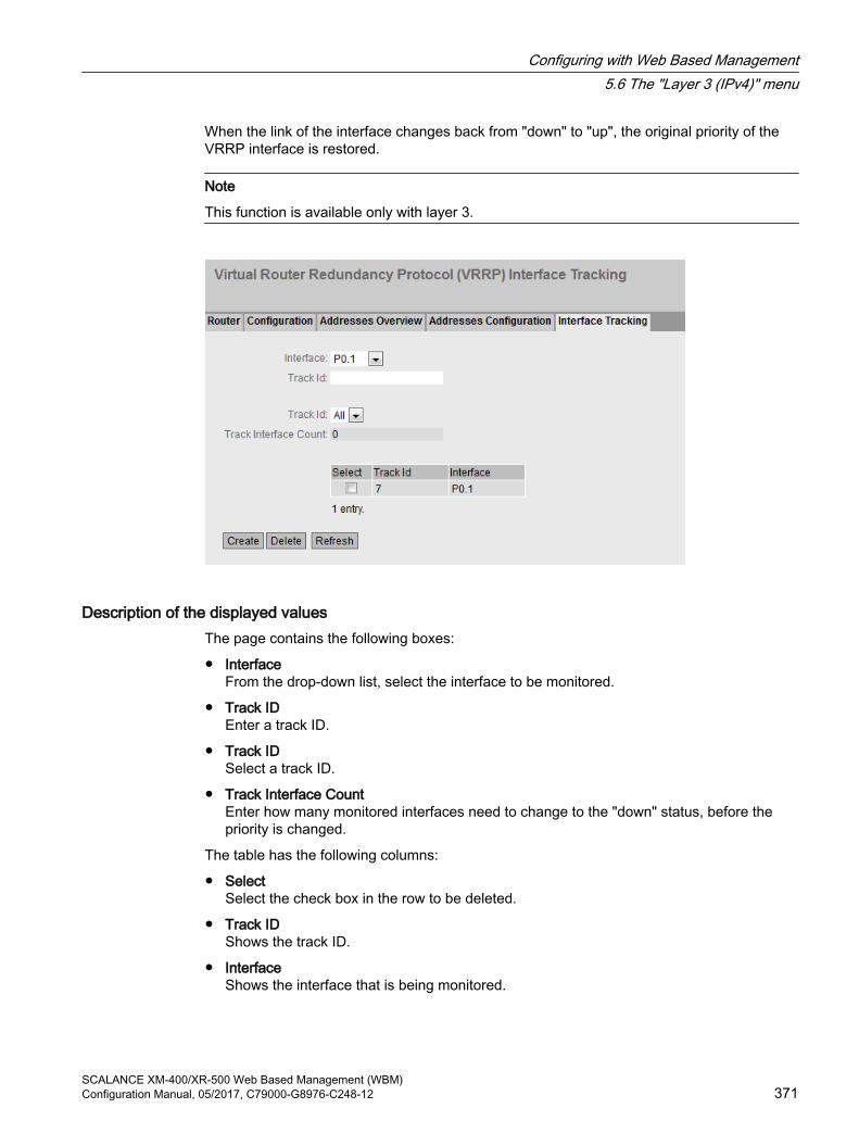
When the link of the interface changes back from "down" to "up", the original priority of the VRRP interface is restored.
Note
This function is available only with layer 3.
Description of the displayed valuesThe page contains the following boxes:
● InterfaceFrom the drop-down list, select the interface to be monitored.
● Track IDEnter a track ID.
● Track IDSelect a track ID.
● Track Interface CountEnter how many monitored interfaces need to change to the "down" status, before the priority is changed.
The table has the following columns:
● SelectSelect the check box in the row to be deleted.
● Track IDShows the track ID.
● InterfaceShows the interface that is being monitored.
Configuring with Web Based Management5.6 The "Layer 3 (IPv4)" menu
SCALANCE XM-400/XR-500 Web Based Management (WBM)Configuration Manual, 05/2017, C79000-G8976-C248-12 371

Steps in configuration1. Select the required interface from the "Interface" drop-down list.
2. In the "Track ID" box, enter the required ID.
3. Click the "Create" button.
4. Select an ID from the "Track-ID" drop-down list:
5. In the "Track Interface Count" enter the number of interfaces.
6. Click the "Set Values" button.
7. Link the monitoring to a VRRP interface in the "Configuration" tab.
5.6.8 VRRPv3
5.6.8.1 Router
Introduction Using the "Create" button, you can create new virtual routers. A maximum of 52 Virtual routers can be configured. You can configure other parameters on the "Configuration" tab.
Note● This function is available only with layer 3.● Simultaneous operation of VRRP and VRRPv3 is not possible.● Select the "VRRPv3" check box to configure VRRPv3.● You can use VRRPv3 on VLAN interfaces. Router ports are not supported.
Configuring with Web Based Management5.6 The "Layer 3 (IPv4)" menu
SCALANCE XM-400/XR-500 Web Based Management (WBM)372 Configuration Manual, 05/2017, C79000-G8976-C248-12

DescriptionThe page contains the following:
● VRRPv3Enable or disable routing using VRRPv3. Can only be enabled when "Layer 3 > Configuration" "IPv6 Routing" is enabled.
● Reply to pings on virtual interfacesWhen enabled, the virtual IPv4 addresses also reply to the ping.
● VRID-TrackingEnable or disable VRID tracking.When enabled, all VRRP instances are monitored. If the status of a VRRP instance changes to "Initialize", the priority of all VRRP instances is reduced to the value "1".If the status of a VRRP instance changes, the original priority of all VRRP instances is restored.
● InterfaceSelect the required VLAN interface operating as virtual router.
● VRIDEnter the ID of the virtual router. This ID defines the group of routers that form a virtual router (VR). In the group, this is the same. It can no longer be used for other groups.Valid values are 1.. 255.
The table has the following columns:
● SelectSelect the check box in the row to be deleted.
● InterfaceShows the Interface that functions as the virtual router.
● VRIDShows the ID of the virtual router.
● Virtual MAC AddressShows the virtual MAC address of the virtual router.
● Primary IP AddressShows the numerically lowest IPv4 address in this VLAN. The entry 0.0.0.0 means that the "Primary" address on this VLAN is used. Otherwise all IPv4 addresses configured on this VLAN in the "Layer 3 (IPv4) > Subnets" menu are valid values.
● Router State Shows the current status of the virtual router. Possible values are:
– MasterThe router is the master router and handles the routing functionality for all assigned IPv4 addresses.
– BackupThe router is the backup router. If the master router fails, the backup router takes over the tasks of the master router.
– InitializeThe virtual router has just been turned on. It will soon change to the "Master" or "Backup" status.
Configuring with Web Based Management5.6 The "Layer 3 (IPv4)" menu
SCALANCE XM-400/XR-500 Web Based Management (WBM)Configuration Manual, 05/2017, C79000-G8976-C248-12 373

● Master IP AddressShows the IPv4 address of the master router.
● PriorityShows the priority of the virtual router.Valid values are 1-254. If an IPv4 address is assigned to the VRRP router that is also actually configured on the local IPv4 interface, the value 255 is entered automatically. All other priorities can be distributed freely among the VRRP routers. The higher the priority, the earlier the VRRP router becomes "Master".
● Advert. InternalShows the interval at which the master router sends VRRPv3 packets.
● PreemptShows the precedence of a router when changing roles between backup and master.
– yesThis router has precedence when changing roles.
– noThis router does not have precedence when changing roles.
VRRP and DHCP serverIf you want to operate a DHCP server on the devices of a VRRP group, the DHCP server must be configured on the master router. Backup routers do not react to DHCP queries. Make sure that the master router is statically configured and that after a failure, becomes the master of the VRRP group again.
Steps in configuration1. Select the "VRRPv3" check box.
2. Select the required interface.
3. Enter the ID of the virtual router in the "VRID" input box.
4. Click the "Create" button. A new row is inserted in the table.
5. Select the "Reply to pings on virtual interfaces" check box so that virtual IPv4 addresses reply to pings as well.
6. Select the "VRID Tracking" check box to monitor the VRID.
7. Click the "Set Values" button. To configure the virtual router, click on the "Configuration" tab.
Configuring with Web Based Management5.6 The "Layer 3 (IPv4)" menu
SCALANCE XM-400/XR-500 Web Based Management (WBM)374 Configuration Manual, 05/2017, C79000-G8976-C248-12

5.6.8.2 Configuration
IntroductionOn this page, you configure the virtual router.
Note
This function is available only with layer 3.
DescriptionThe page contains the following:
● Interface / VRIDSelect the ID of the virtual router to be configured.
● Primary AddressSelect the primary IPv4 address. If the router becomes master router, the router uses this IPv4 address.
Note
If you only configure one subnet on this VLAN, no entry is necessary. The entry is then 0.0.0.0. If you configure more than one subnet on the VLAN and you want a specific IPv4 address to be used as the source address for VRRP packets, select the IPv4 address. Otherwise, the numerically lowest IPv4 address will be used.
Configuring with Web Based Management5.6 The "Layer 3 (IPv4)" menu
SCALANCE XM-400/XR-500 Web Based Management (WBM)Configuration Manual, 05/2017, C79000-G8976-C248-12 375

● MasterIf enabled, the numerically lowest IPv4 address is entered for "Associated IP Address". This means that the numerically lowest IPv4 address of the VRRP router is used as the virtual IP address of the virtual master router. The backup routers in this group must disable the option and use the IPv4 address of the router in "Associated IP address".
● PriorityEnter the priority of this virtual router. Valid values are 1-254. If an IPv4 address is assigned to the VRRPv3 router that is also actually configured on the local IPv4 interface, the value 255 is entered automatically. All other priorities can be distributed freely among the VRRPv3 routers. The higher the priority, the earlier the VRRPv3 router becomes "Master".
● Advertisement intervalEnter the interval in seconds after which a master router sends a VRRPv3 packet again.
● Preempt lower priority Master.Allow precedence when changing roles between backup and master based on the selection process.
● VRRP Compatible ModeWhen enabled, the VRRPv3 router also sends and receives VRRPv2 frames in addition to VRRPv3 frames for configured IPv4 addresses. Only necessary when not all VRRP routers support VRRPv3.
● Track IDSelect a track ID.
● Decrement PriorityEnter the value by which the priority of the VRRPv3 interface will be reduced.
● Current PriorityShows the priority of the VRRPv3 interface after the monitored interface has changed to the "down" status.
Steps in configurationTo configure a virtual router as the master router, follow the steps below:
1. Select the ID of the virtual router you want to configure from the "Interface / VRID" drop-down list.
2. Select the "Status" check box.
3. Select the source address from the "Primary Address" drop-down list.
4. From the "Priority" drop-down list, enter the priority of this virtual router.
5. Select the "Master" check box.
6. Enter the interval in "Advertisement Interval".
7. Select the "Preempt lower priority Master" check box.
8. Select the "VRRP Compatible Mode" check box.
9. Select a track ID.
10.Enter the value by which the priority of the VRRPv3 interface will be reduced
11.Click the "Set Values" button.
Configuring with Web Based Management5.6 The "Layer 3 (IPv4)" menu
SCALANCE XM-400/XR-500 Web Based Management (WBM)376 Configuration Manual, 05/2017, C79000-G8976-C248-12

5.6.8.3 Addresses Overview
OverviewThis page shows which IPv4 addresses the virtual router monitors. Each virtual router can monitor a maximum of 10 IPv4 addresses.
Note
This function is available only with layer 3.
Description of the displayed valuesThe table has the following columns:
● InterfaceShows the Interface that functions as the virtual router.
● VRIDShows the ID of this virtual router.
● Number of AddressesShows the number of IPv4 addresses.
● Associated IP Address (1) ...Associated IP Address (10)Shows the router IPv4 addresses monitored by this virtual router. If a router takes over the role of master, the routing function is taken over by this router for all these IPv4 addresses.
5.6.8.4 Addresses Configuration
Creating or changing the monitored IP addressesOn this page, you can create, modify or delete the IPv4 addresses to be monitored. A maximum of 10 IPv4 addresses can be monitored by a virtual router.
Note
This function is available only with layer 3.
Configuring with Web Based Management5.6 The "Layer 3 (IPv4)" menu
SCALANCE XM-400/XR-500 Web Based Management (WBM)Configuration Manual, 05/2017, C79000-G8976-C248-12 377

DescriptionThe page contains the following:
● Interface / VRIDSelect the ID of the virtual router.
● Associated IP AddressEnter the IPv4 address that the virtual router will monitor. A maximum of 10 IPv4 addresses are possible.
The table has the following columns:
● SelectSelect the check box in the row to be deleted
● Associated IP AddressShows the IPv4 addresses that the virtual router monitors.
Steps in configuration1. Select the ID of the virtual router.
2. Enter the IPv4 address that the virtual router will monitor.
3. Click the "Create" button. A new entry is generated in the table.
5.6.8.5 Interface Tracking
IntroductionOn this page, you configure the monitoring of interfaces.
When the link of a monitored interface changes from "up" to "down", the priority of the assigned VRRP interface is reduced. You configure the value by which the priority is reduced on the page "Layer 3 > VRRP/VRRPv3 > Configuration".
Configuring with Web Based Management5.6 The "Layer 3 (IPv4)" menu
SCALANCE XM-400/XR-500 Web Based Management (WBM)378 Configuration Manual, 05/2017, C79000-G8976-C248-12

When the link of the interface changes back from "down" to "up", the original priority of the VRRP interface is restored.
Note
This function is available only with layer 3.
Description of the displayed valuesThe page contains the following boxes:
● InterfaceFrom the drop-down list, select the interface to be monitored.
● Track IDEnter a track ID.
● Track IDSelect a track ID.
● Track Interface CountEnter how many monitored interfaces need to change to the "down" status, before the priority is changed.
The table has the following columns:
● SelectSelect the check box in the row to be deleted.
● Track IDShows the track ID.
● InterfaceShows the interface that is being monitored.
Configuring with Web Based Management5.6 The "Layer 3 (IPv4)" menu
SCALANCE XM-400/XR-500 Web Based Management (WBM)Configuration Manual, 05/2017, C79000-G8976-C248-12 379

Steps in configuration1. Select the required interface from the "Interface" drop-down list.
2. In the "Track ID" box, enter the required ID.
3. Click the "Create" button.
4. Select an ID from the "Track-ID" drop-down list:
5. In the "Track Interface Count" enter the number of interfaces.
6. Click the "Set Values" button.
7. Link the monitoring to a VRRP interface in the "Configuration" tab.
5.6.9 OSPFv2
5.6.9.1 Configuration
Introduction On this page, you configure the routing using OSPFv2..
Note
This function is available only with layer 3.
Configuring with Web Based Management5.6 The "Layer 3 (IPv4)" menu
SCALANCE XM-400/XR-500 Web Based Management (WBM)380 Configuration Manual, 05/2017, C79000-G8976-C248-12

Description of the displayed valuesThe page contains the following boxes
● OSPFv2Enable or disable routing using OSPFv2.
● Router IDEnter the name of one of the OSPFv2 interfaces. The name is entered in the IP address format and does not need to match the local IP address. The router ID must be unique in the network.
● OSPFv2-RFC1583 CompatibilityEnable the option if you still have old OSPFv2 routers in operation that are not compatible with RFC 2328.
● Border RouterShows the status of the OSPFv2 router. If the local system is an active member in at least 2 areas, this is an area border router.
● AS Border RouterSpecify whether the router is an AS border router. An AS border router intercedes between multiple autonomous systems, for example if you have an additional RIP network. An AS border router is also necessary to add and to distribute static routes.
● New LSA ReceivedShows the number of received LSAs.Updates and local LSAs are not counted.
● New LSA ConfiguredShows the number of different LSAs sent by this local system.
● External LSA MaximumTo limit the number of entries of external LSAs in the database, enter the maximum number of external LSAs.
● Exit Interval [s]Enter the interval after which the OSPFv2 router once again attempts to come out of the overflow status. A 0 means that the OSPF router attempts to exit the overflow status only following a restart.
● Inbound FilterSelect a route map that filters inbound routes.
● Redistribute Routes (Default/Connected/Static)Specify which known routes are distributed using OSPFv2. You can make different decisions for the route types Default, Connected and Static.
Note
The options can only be enabled on an AS border router. Enabling the Default and Static options, in particular, can cause problems if they are enabled at too many points in the network, for example, forwarding loops.
● Route MapSelect a route map that filters which routes are forwarded using RIPv2.
Configuring with Web Based Management5.6 The "Layer 3 (IPv4)" menu
SCALANCE XM-400/XR-500 Web Based Management (WBM)Configuration Manual, 05/2017, C79000-G8976-C248-12 381
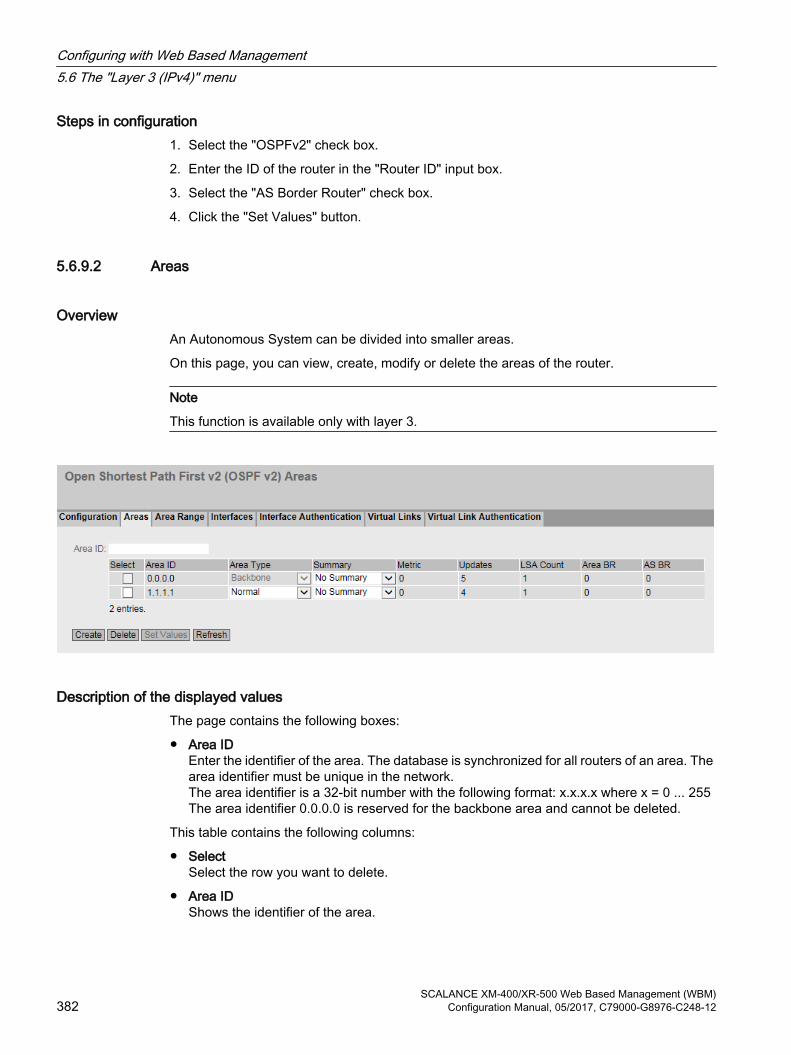
Steps in configuration1. Select the "OSPFv2" check box.
2. Enter the ID of the router in the "Router ID" input box.
3. Select the "AS Border Router" check box.
4. Click the "Set Values" button.
5.6.9.2 Areas
OverviewAn Autonomous System can be divided into smaller areas.
On this page, you can view, create, modify or delete the areas of the router.
Note
This function is available only with layer 3.
Description of the displayed valuesThe page contains the following boxes:
● Area IDEnter the identifier of the area. The database is synchronized for all routers of an area. The area identifier must be unique in the network.The area identifier is a 32-bit number with the following format: x.x.x.x where x = 0 ... 255The area identifier 0.0.0.0 is reserved for the backbone area and cannot be deleted.
This table contains the following columns:
● SelectSelect the row you want to delete.
● Area IDShows the identifier of the area.
Configuring with Web Based Management5.6 The "Layer 3 (IPv4)" menu
SCALANCE XM-400/XR-500 Web Based Management (WBM)382 Configuration Manual, 05/2017, C79000-G8976-C248-12

● Area TypeSelect the area type in the drop-down list.
– Standard
– Stub
– NSSA
– Backbone
● SummarySpecify whether summary LSAs are generated for this area.
– Summary: Summary LSAs are generated and sent to the area.
– No Summary: Summary LSAs are not generated and sent to the area.
● MetricDisplays the costs for the OSPFv2 interface.
● UpdatesShows the number of recalculations of the routing tables.
● LSA CountShows the number of LSAs in the database.
● Area BRShows the number of reachable area border routers (ABR) within this area.
● AS BRShows the number of reachable autonomous system border routers (ASBR) in this area.
Steps in configuration1. Enter the ID for the area in the "Area ID" input box.
2. Click the "Create" button. A new entry is generated in the table.
3. Select the type of area, for example Stub in the "Area Type" drop-down list.
4. Select the "Summary LSA" entry in the "Summary" drop-down list.
5. Click the "Set Values" button.
5.6.9.3 Area Range
Creating a new OSPFv2 area range Using the "Create" button in the "OSPFv2 Area Range" menu, up to four networks can be grouped together under one area ID. The method is used only with area border routers. This means that an area border router only advertises one route for grouped areas to the outside.
Note
This function is available only with layer 3.
Configuring with Web Based Management5.6 The "Layer 3 (IPv4)" menu
SCALANCE XM-400/XR-500 Web Based Management (WBM)Configuration Manual, 05/2017, C79000-G8976-C248-12 383

Description of the displayed boxesThe page contains the following boxes:
● Area IDSelect the ID of the area from the drop-down list. You specify the ID on the "Areas" tab.
● Subnet AddressEnter the IPv4 address of the network that will be grouped.
● Subnet maskEnter the subnet mask of the network that will be grouped.
This table contains the following columns:
● SelectSelect the row you want to delete.
● Area IDShows the ID of the area.
● Subnet AddressShows the IP address of the network that will be grouped.
● Subnet Mask Shows the subnet mask of the network that will be grouped.
● Advertise Enable this option to advertise the grouped network.
Steps in configuration1. Select the ID of the area from the drop-down list.
2. Enter the IP address of the network that will be grouped.
3. Enter the subnet mask of the network that will be grouped.
4. Click the "Create" button. A new entry is generated in the table.
5. Enable the "Advertise" option to advertise the grouped network.
6. Click the "Set Values" button.
Configuring with Web Based Management5.6 The "Layer 3 (IPv4)" menu
SCALANCE XM-400/XR-500 Web Based Management (WBM)384 Configuration Manual, 05/2017, C79000-G8976-C248-12

5.6.9.4 Interfaces
OverviewOn this page, you can configure OSPFv2 interfaces.
Note
This function is available only with layer 3.
Description of the displayed boxesThe page contains the following boxes:
● IP AddressSelect the IPv4 address of the OSPFv2 interface from the drop-down list.
● Area ID Select the ID of the area that is connected to the OSPFv2 interface from the drop-down list.
Note
For the secondary interface select the same Area ID as for the corresponding primary interface. The information whether an address type is primary or secondary can be found in the "Address Type" column on the "Layer 3 (IPv4) > Subnets > Overview" page.
Select the ID of the area that is connected to the OSPFv2 interface from the drop-down list. The table has the following columns:
● SelectSelect the row you want to delete.
● IP addressShows the IPv4 address of the OSPFv2 interface
Configuring with Web Based Management5.6 The "Layer 3 (IPv4)" menu
SCALANCE XM-400/XR-500 Web Based Management (WBM)Configuration Manual, 05/2017, C79000-G8976-C248-12 385
● Area ID Select the ID of the area that is connected to the OSPFv2 interface from the drop-down list.
● Passive InterfaceSpecify the behavior of the interface:
– Enabled: No OSPFv2 information (e.g. Hello frames and LSDB updates) is sent via this interface and learned.
– Disabled: OSPFv2 information is sent via this interface and learned.
● Metric Enter the costs for the OSPFv2 interface.
● PriorityEnter the router priority. The priority is only relevant for selecting the designated router or designated border router. This parameter can be selected differently on routers within the same subnet. Range of values: 0 to 255 Default setting: 1
● Trans. Delay Enter the expected delay when sending a connection update.Range of values: 1 s to 3600 sDefault: 1 s
● Retrans. Delay Enter the time after which an OSPFv2 packet is transferred again if no confirmation was received.Range of values: 1 s to 3600 sDefault: 5 s
● Hello IntervalEnter the interval between two Hello packets.Range of values: 1 s to 65,535 sDefault: 10 s
● Dead IntervalEnter the interval after which the neighbor router is marked as "failed" if no more Hello packets are received from it during this time.Default: 40 s
Steps in configuration1. Select the IPv4 address of the OSPFv2 interface from the "IP Address" drop-down list.
2. Select the ID of the area with which the OSPFv2 interface is connected from the "Area ID" drop-down list.
3. Click the "Create" button. A new entry is generated in the table.
4. Select the required settings or use the factory defaults.
5. Click the "Set Values" button.
Configuring with Web Based Management5.6 The "Layer 3 (IPv4)" menu
SCALANCE XM-400/XR-500 Web Based Management (WBM)386 Configuration Manual, 05/2017, C79000-G8976-C248-12

5.6.9.5 Interface Authentication
Configuring the interface authenticationOn this page, you define the authentication of the interface.
Description of the displayed boxesThe page contains the following boxes:
● OSPF interfaceSelect the OSPFv2 interface for which you want to configure authentication.
● Authentication TypeSelect the authentication method. You have the following options:
– NoneNo authentication
– SimpleAuthentication using an unencrypted password
– MD5Authentication using MD5
Section "Simple Authentication"
● PasswordEnter a password.
● ConfirmationConfirm the entered password.
Configuring with Web Based Management5.6 The "Layer 3 (IPv4)" menu
SCALANCE XM-400/XR-500 Web Based Management (WBM)Configuration Manual, 05/2017, C79000-G8976-C248-12 387
Section "MD5 Authentication"
● Authentication Key IDEnter the identifier of the MD5 authentication key.Enter the ID for MD5 authentication with which the password will be used as a key.Since the key ID is transferred with the protocol, the same key must be stored under the same key ID on all neighboring routers.
The table has the following columns:
● SelectSelect the row you want to delete.
● Authentication Key IDCan only be edited if you set the MD5 authentication method. It is only possible to use several keys there.
● MD5 KeyEnter the MD5 key.
● MD5 Key ConfirmationConfirm the entered key.
● Youngest Key IDShows whether or not the MD5 key is the latest key ID.
Steps in configuration1. Select the OSPFv2 interface and the authentication method from the drop-down lists.
2. Enter the following data in the relevant input box:
– Password and confirmation for simple authentication.
– Authentication key ID for MD5 authentication
3. Click the "Create" button.
4. Enter the MD5 key and the confirmation of the MD5 key.
5. Click the "Set Values" button.
5.6.9.6 Virtual Links
Overview Due to the protocol, each area border router must have access to the backbone area. If a router is not connected directly to the backbone area, a virtual link to it is created.
Note
This function is available only with layer 3.
Configuring with Web Based Management5.6 The "Layer 3 (IPv4)" menu
SCALANCE XM-400/XR-500 Web Based Management (WBM)388 Configuration Manual, 05/2017, C79000-G8976-C248-12
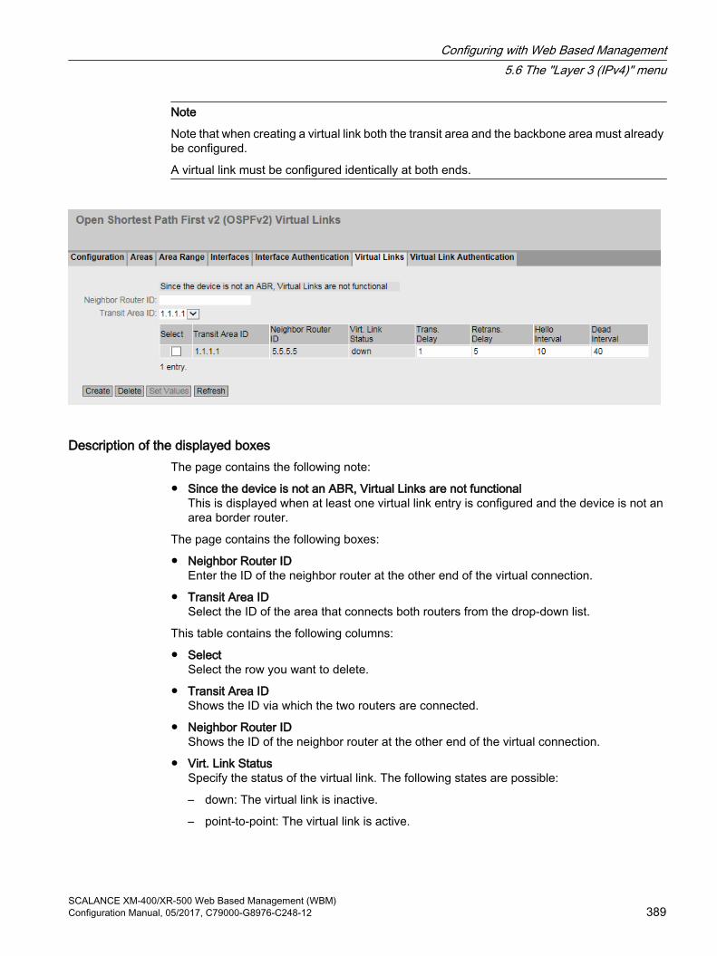
Note
Note that when creating a virtual link both the transit area and the backbone area must already be configured.
A virtual link must be configured identically at both ends.
Description of the displayed boxesThe page contains the following note:
● Since the device is not an ABR, Virtual Links are not functionalThis is displayed when at least one virtual link entry is configured and the device is not an area border router.
The page contains the following boxes:
● Neighbor Router IDEnter the ID of the neighbor router at the other end of the virtual connection.
● Transit Area IDSelect the ID of the area that connects both routers from the drop-down list.
This table contains the following columns:
● SelectSelect the row you want to delete.
● Transit Area IDShows the ID via which the two routers are connected.
● Neighbor Router IDShows the ID of the neighbor router at the other end of the virtual connection.
● Virt. Link Status Specify the status of the virtual link. The following states are possible:
– down: The virtual link is inactive.
– point-to-point: The virtual link is active.
Configuring with Web Based Management5.6 The "Layer 3 (IPv4)" menu
SCALANCE XM-400/XR-500 Web Based Management (WBM)Configuration Manual, 05/2017, C79000-G8976-C248-12 389

● Trans. Delay Enter the expected delay when sending a link update packet.Range of values: 1 s to 3600 sDefault: 1 s
● Retrans. DelayEnter the time after which a packet is transferred again if no confirmation was received.Range of values: 1 s to 3600 sDefault: 5 s
● Hello IntervalEnter the interval between two Hello packets.Range of values: 1 s to 65,535 sDefault: 10 s
● Dead IntervalEnter the interval after which the neighbor router counts as "failed" if no more Hello packets are received from it during this time. Default setting: 40 s
Steps in configuration1. Enter the ID of the neighbor router at the other end of the virtual link in "Neighbor Router
ID".
2. Select the area ID that connects the two routers from the "Transit Area ID" drop-down list.
3. Click the "Create" button. A new entry is generated in the table.
4. Enter the appropriate values in "Transit Delay", "Retrans. Delay" and "Dead Interval".
5. Click the "Set Values" button.
Configuring with Web Based Management5.6 The "Layer 3 (IPv4)" menu
SCALANCE XM-400/XR-500 Web Based Management (WBM)390 Configuration Manual, 05/2017, C79000-G8976-C248-12
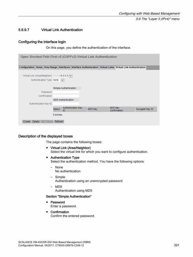
5.6.9.7 Virtual Link Authentication
Configuring the interface loginOn this page, you define the authentication of the interface.
Description of the displayed boxesThe page contains the following boxes:
● Virtual Link (Area/Neighbor)Select the virtual link for which you want to configure authentication.
● Authentication TypeSelect the authentication method. You have the following options:
– NoneNo authentication
– SimpleAuthentication using an unencrypted password
– MD5Authentication using MD5
Section "Simple Authentication"
● PasswordEnter a password.
● ConfirmationConfirm the entered password.
Configuring with Web Based Management5.6 The "Layer 3 (IPv4)" menu
SCALANCE XM-400/XR-500 Web Based Management (WBM)Configuration Manual, 05/2017, C79000-G8976-C248-12 391

Section "MD5 Authentication"
● Authentication Key IDEnter the identifier of the MD5 authentication key.Enter the ID for MD5 authentication with which the password will be used as a key.Since the key ID is transferred with the protocol, the same key must be stored under the same key ID on all neighboring routers.
The table has the following columns:
● SelectSelect the row you want to delete.
● Authentication Key IDCan only be edited if you set the MD5 authentication method. It is only possible to use several keys there.
● MD5 KeyEnter the MD5 key.
● MD5 Key ConfirmationConfirm the entered key.
● Youngest Key IDShows whether or not the MD5 key is the latest key ID.
Steps in configuration1. Select the virtual connection and the authentication method from the drop-down lists.
2. Enter the following data in the relevant input box:
– Password and confirmation for simple authentication.
– Authentication key ID for MD5 authentication
3. Click the "Create" button.
4. Enter the MD5 key and the confirmation of the MD5 key.
5. Click the "Set Values" button.
5.6.10 RIPv2
5.6.10.1 ConfigurationOn this page, you configure the routing using RIPv2.
Note
RIPv2 is available only on layer 3.
Configuring with Web Based Management5.6 The "Layer 3 (IPv4)" menu
SCALANCE XM-400/XR-500 Web Based Management (WBM)392 Configuration Manual, 05/2017, C79000-G8976-C248-12

Settings
Figure 5-15 RIPv2 Configuration
● RIPv2Enable or disable routing using RIPv2.
● Inbound FilterSelect a route map that filters inbound routes.
● Redistribute RoutesSpecify which known routes are distributed using RIPv2.The following types of route exist:
– Static Default
– Connected
– Static
– OSPF
● Route MapSelect a route map that filters which routes are forwarded using RIPv2.
5.6.10.2 Interfaces
OverviewOn this page, you can configure RIPv2 interfaces.
Note
RIPv2 is available only on layer 3.
Configuring with Web Based Management5.6 The "Layer 3 (IPv4)" menu
SCALANCE XM-400/XR-500 Web Based Management (WBM)Configuration Manual, 05/2017, C79000-G8976-C248-12 393
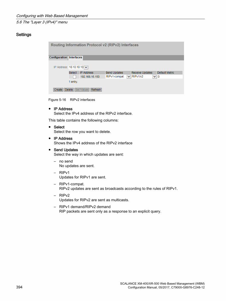
Settings
Figure 5-16 RIPv2 interfaces
● IP AddressSelect the IPv4 address of the RIPv2 interface.
This table contains the following columns:
● SelectSelect the row you want to delete.
● IP AddressShows the IPv4 address of the RIPv2 interface
● Send UpdatesSelect the way in which updates are sent:
– no sendNo updates are sent.
– RIPv1Updates for RIPv1 are sent.
– RIPv1-compat.RIPv2 updates are sent as broadcasts according to the rules of RIPv1.
– RIPv2Updates for RIPv2 are sent as multicasts.
– RIPv1 demand/RIPv2 demandRIP packets are sent only as a response to an explicit query.
Configuring with Web Based Management5.6 The "Layer 3 (IPv4)" menu
SCALANCE XM-400/XR-500 Web Based Management (WBM)394 Configuration Manual, 05/2017, C79000-G8976-C248-12

● Receive UpdatesSelect the form in which received updates are accepted:
– no receiveNo updates are received.
– RIPv1Only updates of RIPv1 are received.
– RIPv2Only updates of RIPv2 are received.
– RIPv1/v2Updates of RIPv1 and RIPv2 are received.
● Default MetricEnter the costs for the RIPv2 interface.
5.6.11 IGMP
IGMP On this page, you configure IGMP (Internet Group Management Protocol).
IGMP is a network protocol used for IP multicast. When IP muticasting IP packets with one IP address are distributed to multiple clients at the same time. IGMP can manage dynamic and static multicast groups.
Description of the displayed boxes
The page contains the following boxes:
● IGMPEnable or disable IGMP (Internet Group Management Protocol) for the entire device.
● InterfaceSelect the required interface on which you want to configure IGMP.
Configuring with Web Based Management5.6 The "Layer 3 (IPv4)" menu
SCALANCE XM-400/XR-500 Web Based Management (WBM)Configuration Manual, 05/2017, C79000-G8976-C248-12 395

The table has the following columns:
● SelectSelect the row you want to delete.
● InterfaceShows the interface.
● Version Select the version of IGMP.
● Query Interval [s]Define the interval at which the multicast router sends IGMP queries.Specified in seconds
● Max. Response Time [1/10 s]Specify the period of time in an IGMP query that the client has to respond to a query.Specified in tenths of seconds
● Explicit TrackingEnable or disable the "Explicit Tracking" function for the interface.If the "Explicit Tracking" function is enabled, the multicast router tracks precisely which clients log on to a multicast group (Join) and log off (Leave). As soon as the last client has logged off from a multicast group, the multicast router deletes the multicast group. Since the multicast router has precise information about the logged on and logged off clients, the multicast router does not need to query whether a further client wants to receive the multicast.
● Admin StatusEnable or disable IGMP on the interface.
● Operating StatusShows the operating status of the interface, see also "System > Ports > Overview".
– Up
– Down
Steps in configuration1. Select the "IGMP" check box.
2. Select an interface.
3. Click the "Create" button.
4. Select the required settings in the table.
5. Click the "Set Values" button.
Configuring with Web Based Management5.6 The "Layer 3 (IPv4)" menu
SCALANCE XM-400/XR-500 Web Based Management (WBM)396 Configuration Manual, 05/2017, C79000-G8976-C248-12

5.6.12 PIM
5.6.12.1 PIMOn this page, you configure PIM.
Note
PIM is available only on layer 3.
Settings
● PIM RoutingEnable or disable PIM globally on the device.
● Static Rendezvous Point (RP)Enable or disable depending on whether the device should operate as a static rendezvous point.
● Bidirectional MulticastEnable or disable the "bidirectional multicast" functionality globally on the device.
5.6.12.2 Interface
OverviewOn this page, you configure PIM interfaces.
Note
PIM is available only on layer 3.
Configuring with Web Based Management5.6 The "Layer 3 (IPv4)" menu
SCALANCE XM-400/XR-500 Web Based Management (WBM)Configuration Manual, 05/2017, C79000-G8976-C248-12 397

Settings
The page contains the following boxes:
● InterfaceSelect a VLAN IP interface.
● PIMIf you select this check box, The selected interface is assigned PIM.
● Bootstrap Router (BSR) CandidateIf you enable this check box, you specify that the interface will become a candidate for the bootstrap router. A BSR coordinates the rendezvous points in a PIM network.
● BSR Candidate ValueEnter the priority of the interface as BSR candidate.Which candidate becomes the BSR is decided based on the priority. The candidate with the highest priority becomes the BSR.If the same priority is set for two candidates, when necessary the decision is made based on the IP address. The interface with the higher IP address becomes BSR.A BSR coordinates the rendezvous points in a PIM network.
● Designated Router (DR) PriorityEnter the DR priority of the interface.Which candidate becomes the DR is decided based on the DR priority. The candidate with the highest priority becomes the DR.If the same priority is set for two candidates, when necessary the decision is made based on the IP address. The interface with the higher IP address becomes DR.The DR forwards the IGMP Joins to the rendezvous point.
● BSR BorderWhen enabled there is no BSR communication via this interface. As a result a PIM network is divided into PIM domains.
5.6.12.3 RP Static
OverviewOn this page you specify which interfaces will become static rendezvous points.
Configuring with Web Based Management5.6 The "Layer 3 (IPv4)" menu
SCALANCE XM-400/XR-500 Web Based Management (WBM)398 Configuration Manual, 05/2017, C79000-G8976-C248-12
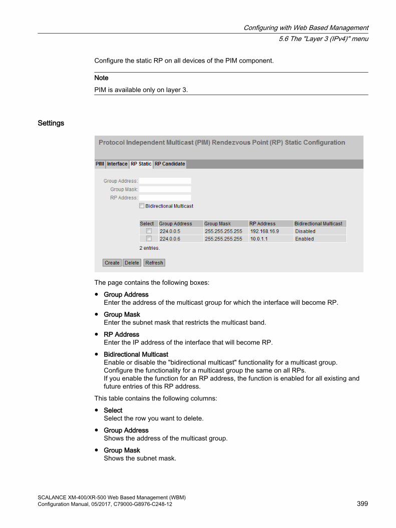
Configure the static RP on all devices of the PIM component.
Note
PIM is available only on layer 3.
Settings
The page contains the following boxes:
● Group AddressEnter the address of the multicast group for which the interface will become RP.
● Group MaskEnter the subnet mask that restricts the multicast band.
● RP AddressEnter the IP address of the interface that will become RP.
● Bidirectional MulticastEnable or disable the "bidirectional multicast" functionality for a multicast group.Configure the functionality for a multicast group the same on all RPs.If you enable the function for an RP address, the function is enabled for all existing and future entries of this RP address.
This table contains the following columns:
● SelectSelect the row you want to delete.
● Group AddressShows the address of the multicast group.
● Group MaskShows the subnet mask.
Configuring with Web Based Management5.6 The "Layer 3 (IPv4)" menu
SCALANCE XM-400/XR-500 Web Based Management (WBM)Configuration Manual, 05/2017, C79000-G8976-C248-12 399

● RP AddressShows the IP address of the RP.
● Bidirectional MulticastShows whether the "bidirectional multicast" functionality is activated or deactivated for a multicast group.
5.6.12.4 RP Candidate
OverviewOn this page you specify which interfaces will be candidates for the rendezvous point (RP).
Within a PIM network you can configure several candidates for the RP. The BSR coordinates the candidates and decides on the RP.
Note
PIM is available only on layer 3.
Settings
The page contains the following boxes:
● Group AddressEnter the address of the multicast group.
● Group MaskEnter the subnet mask that restricts the multicast band.
Configuring with Web Based Management5.6 The "Layer 3 (IPv4)" menu
SCALANCE XM-400/XR-500 Web Based Management (WBM)400 Configuration Manual, 05/2017, C79000-G8976-C248-12

● RP InterfaceSelect the interface that will become the RP candidate.
● Bidirectional MulticastEnable or disable the "bidirectional multicast" functionality for a multicast group.Configure the functionality for a multicast group the same on all RPs.If you enable the function for an RP interface, the function is enabled for all existing and future entries of this RP interface.
This table contains the following columns:
● SelectSelect the row you want to delete.
● Group AddressShows the address of the multicast group.
● Group MaskShows the subnet mask.
● RP CandidateShows the IP address of the RP.
● Bidirectional MulticastShows whether the "bidirectional multicast" functionality is activated or deactivated for a multicast group.
● RP PriorityEnter the priority of the interface.Which candidate becomes the rendezvous point is decided based on the RP priority. The candidate with the highest priority becomes the RP. The lower the value, the higher the priority.If the same priority is set for two candidates, when necessary the decision is made based on the IP address. The interface with the lowest IP address becomes RP.
5.6.13 MSDP
5.6.13.1 MSDP
OverviewOn this page, you can configure MSDP.
MSDP (Multicast Source Discovery Protocol) is supported within a PIM-SM domain in combination with anycast RPs. Anycast RPs involve a redundancy concept for RPs. The RPs involved all receive the same IP address and are made known in the network. The RPs are linked together via MSDP sessions. The RPs synchronize their multicast sources via source active messages.
Configure MSDP on the rendezvous points.
Configuring with Web Based Management5.6 The "Layer 3 (IPv4)" menu
SCALANCE XM-400/XR-500 Web Based Management (WBM)Configuration Manual, 05/2017, C79000-G8976-C248-12 401
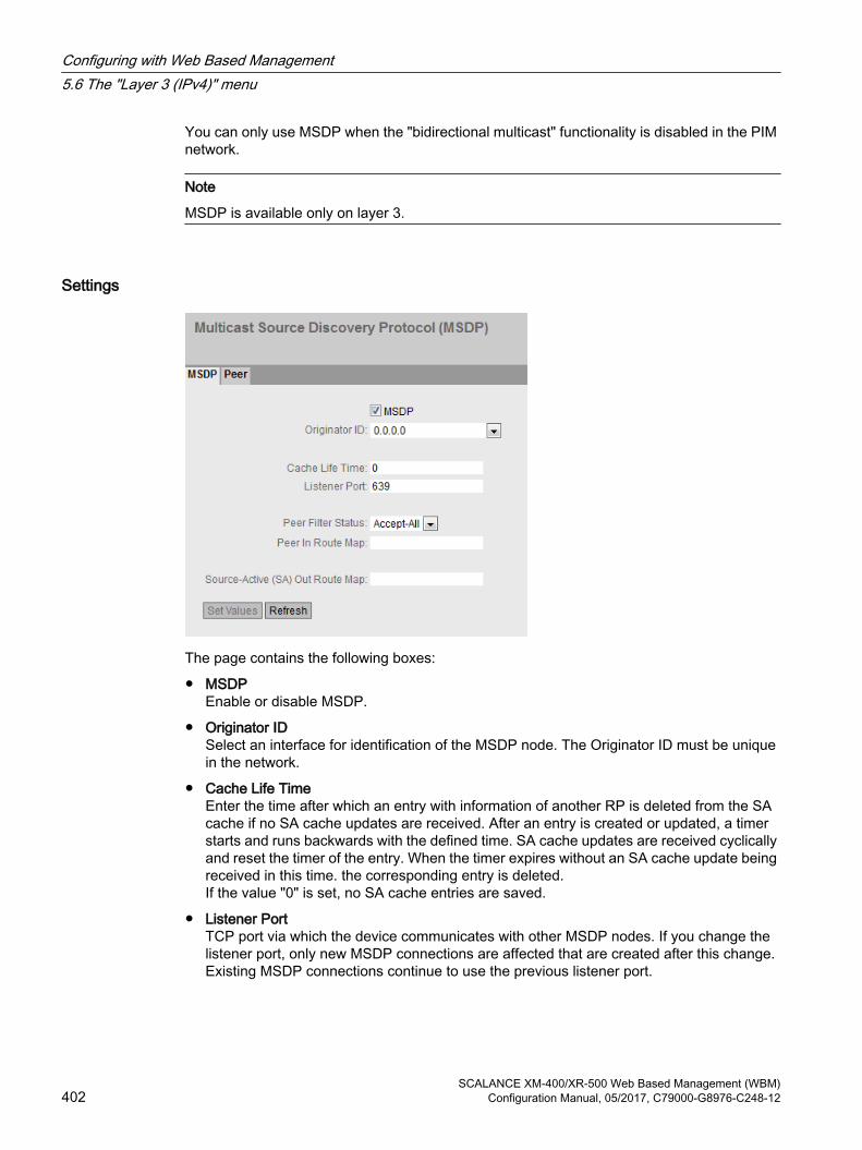
You can only use MSDP when the "bidirectional multicast" functionality is disabled in the PIM network.
Note
MSDP is available only on layer 3.
Settings
The page contains the following boxes:
● MSDPEnable or disable MSDP.
● Originator IDSelect an interface for identification of the MSDP node. The Originator ID must be unique in the network.
● Cache Life TimeEnter the time after which an entry with information of another RP is deleted from the SA cache if no SA cache updates are received. After an entry is created or updated, a timer starts and runs backwards with the defined time. SA cache updates are received cyclically and reset the timer of the entry. When the timer expires without an SA cache update being received in this time. the corresponding entry is deleted.If the value "0" is set, no SA cache entries are saved.
● Listener PortTCP port via which the device communicates with other MSDP nodes. If you change the listener port, only new MSDP connections are affected that are created after this change. Existing MSDP connections continue to use the previous listener port.
Configuring with Web Based Management5.6 The "Layer 3 (IPv4)" menu
SCALANCE XM-400/XR-500 Web Based Management (WBM)402 Configuration Manual, 05/2017, C79000-G8976-C248-12

5.6.13.2 Peer
OverviewOn this page, you configure MSDP partners.
Note
MSDP is available only on layer 3.
Settings
The page contains the following boxes:
● Peer AddressEnter the IP address of the MSDP partner to which the device will establish a connection.
● Connected InterfaceSelect the interface via which the device communicates with the MSDP partner.
This table contains the following columns:
● SelectSelect the row you want to delete.
● Peer AddressShows the address of the MSDP partner.
● Local AddressShows the IP address of the interface via which the device communicates with the MSDP partner.
● Admin StatusEnable or disable the connection.
Configuring with Web Based Management5.6 The "Layer 3 (IPv4)" menu
SCALANCE XM-400/XR-500 Web Based Management (WBM)Configuration Manual, 05/2017, C79000-G8976-C248-12 403

● Connection StatusShows the status of the connection.
– ListeningThe device is waiting for the connection.
– ConnectingConnection establishment
– EstablishedThe connection is established.
– InactiveThe connection is not active.
– DisabledThe connection is disabled.
● Keepalive Interval[s]Define the interval at which the device sends keepalive messages to the MSDP partners.
● Peer Hold Time Interval[s]Define the time after which an MSDP connection is terminated if no keepalive messages are received from the MSDP partner.
● Connect Retry Interval[s]Define the interval after which an attempt is made to establish a connection. If there is no MSDP connection to a partner, when the Connect Retry Interval elapses, an attempt is made to establish a connection.
● TTL ThresholdDefine the maximum number of routers that may be passed through on the way to the MSDP partner (hop count). If the specified value used is exceeded, the frame is discarded.
5.7 The "Layer 3 (IPv6)" menu
5.7.1 Configuration
IntroductionThe page contains the overview of the layer 3 functions for IPv6. On this page, you enable or disable the required layer 3 function.
The functions "IPv6 Routing", "VRRPv3" and "OSPFv3" are only available with Layer 3 (IPv6).
Configuring with Web Based Management5.7 The "Layer 3 (IPv6)" menu
SCALANCE XM-400/XR-500 Web Based Management (WBM)404 Configuration Manual, 05/2017, C79000-G8976-C248-12

DescriptionThe page contains the following:
● IPv6 Routing (only available with devices with a layer 3 license)
– EnabledIPv6 routing is enabled. If IPv4 routing is not enabled on the device this is also enabled with this function.
– DisabledIPv6 routing is disabled.
● VRRPv3 (only available with devices with a layer 3 license)Enable or disable routing using VRRPv3. To use VRRPv3 , first enable the IPv6 routing function. You can configure other settings in "Layer 3 (IPv6)> VRRPv3".
● OSPFv3 (only available with devices with a layer 3 license)Enable or disable routing using OSPFv3. To use OSPFv3 , first enable the IPv6 routing function. You can configure other settings in "Layer 3 (IPv6) > OSPFv3".
Steps in configuration1. To use the required function, select the corresponding check box.
2. Click the "Set Values" button.
Configuring with Web Based Management5.7 The "Layer 3 (IPv6)" menu
SCALANCE XM-400/XR-500 Web Based Management (WBM)Configuration Manual, 05/2017, C79000-G8976-C248-12 405

5.7.2 Subnets
Connected SubnetsOn this page, you can enable IPv6 on the interface. The interface is also called an IPv6 interface. An IPv6 interface can have several IPv6 addresses.
DescriptionThe page contains the following:
● InterfaceSelect the IP interface on which IPv6 will be enabled.
● IPv6 EnableEnable or disable IPv6 on the interface.
NoteDisabling IPv6
If IPv6 is enabled on an interface, you can only disable IPv6 by deleting interface.
● IPv6 AddressEnter the IPv6 address. The entry depends on the selected address type.
● Prefix LengthEnter the number of left-hand bits belonging to the prefix
● IPv6 Address TypeSelect the address type.
– Unicast
– Anycast
– Link Local IPv6 address is only valid on the link
Configuring with Web Based Management5.7 The "Layer 3 (IPv6)" menu
SCALANCE XM-400/XR-500 Web Based Management (WBM)406 Configuration Manual, 05/2017, C79000-G8976-C248-12

The table has the following columns:
● SelectSelect the check box in the row to be deleted.
● Interface NameShows the name of the interface.
● IPv6 AddressShows the IP address of the subnet.
● Prefix LengthShows the prefix length.
● IPv6 Address TypeDisplays the address type. The following values are possible:
– Unicast
– Anycast
– Link Local
● LoopbackShows whether or not the "loopback" property is enabled. You configure the "loopback" property on the page "Layer 3 (IPv4) > Subnets > Overview".
Steps in configurationForming a link local address automatically
1. Select the required interface.
2. Enable IPv6.
3. Click the "Create" button. In the table an entry with the interface is created and the automatically formed IPv6 address is displayed.
Assigning link local address
1. Select the required interface.
2. Enable IPv6.
3. In "IPv6 Address" enter the link local address, e.g. FE80::21B:1BFF:FE40:9155
4. Enter "128" in "Prefix Length".
5. For "IPv6 Address Type" select the entry "Link Local".
6. Click the "Create" button. In the table an entry with the interface is created and the IPv6 address is displayed.
Configuring with Web Based Management5.7 The "Layer 3 (IPv6)" menu
SCALANCE XM-400/XR-500 Web Based Management (WBM)Configuration Manual, 05/2017, C79000-G8976-C248-12 407
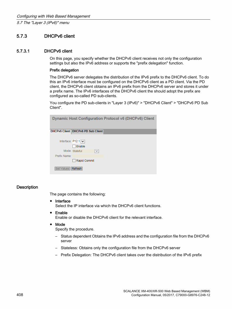
5.7.3 DHCPv6 client
5.7.3.1 DHCPv6 clientOn this page, you specify whether the DHCPv6 client receives not only the configuration settings but also the IPv6 address or supports the "prefix delegation" function.
Prefix delegation
The DHCPv6 server delegates the distribution of the IPv6 prefix to the DHCPv6 client. To do this an IPv6 interface must be configured on the DHCPv6 client as a PD client. Via the PD client, the DHCPv6 client obtains an IPv6 prefix from the DHCPv6 server and stores it under a prefix name. The IPv6 interfaces of the DHCPv6 client the should adopt the prefix are configured as so-called PD sub-clients.
You configure the PD sub-clients in "Layer 3 (IPv6)" > "DHCPv6 Client" > "DHCPv6 PD Sub Client".
DescriptionThe page contains the following:
● InterfaceSelect the IP interface via which the DHCPv6 client functions.
● EnableEnable or disable the DHCPv6 client for the relevant interface.
● ModeSpecify the procedure.
– Status dependent Obtains the IPv6 address and the configuration file from the DHCPv6 server
– Stateless: Obtains only the configuration file from the DHCPv6 server
– Prefix Delegation: The DHCPv6 client takes over the distribution of the IPv6 prefix
Configuring with Web Based Management5.7 The "Layer 3 (IPv6)" menu
SCALANCE XM-400/XR-500 Web Based Management (WBM)408 Configuration Manual, 05/2017, C79000-G8976-C248-12

● Prefix NameEnter the prefix name that will be further distributed by the DHCPv6 router. Can only be edited with the "Prefix Delegation" procedure. The DHCPv6 router stores IPv6 prefix of the DHCPv6 server under this name.
● Rapid CommitWhen enabled the procedure for the IPv6 address assignment is shortened. Instead of 4 DHCPv6 messages (SOLICIT, ADVERTISE , REQUEST, REPLY) only 2 DHCPv6 messages (SOLICIT, REPLY) are used. You will find further information on the messages in RFC 3315.
Steps in configuration 1. Select the interface
2. Enable the DHCPv6 client.
3. Select the mode.
4. Enter a name for the prefix. Only necessary if "Prefix Delegation" is set as the mode.
5. Click the "Set Values" button.
5.7.3.2 DHCPv6 PD Sub ClientOn this page you specify which IPv6 interfaces of the DHCPv6 client will adopt the prefix. This achieved by assigning the prefix name followed by a prefix and the required prefix length to them as the IP address. Here, the first bits of the configured prefix are replaced by the values stored in the prefix name.
Example:
Under the prefix name "test", the following IPv6 prefix is stored: 2001:DB8:1234::/48
Prefix = 2002:AF9:5678::1
Prefix length = 64
This results in the following IPv6 address 2001:DB8:1234::1
Configuring with Web Based Management5.7 The "Layer 3 (IPv6)" menu
SCALANCE XM-400/XR-500 Web Based Management (WBM)Configuration Manual, 05/2017, C79000-G8976-C248-12 409

DescriptionThe page contains the following:
● InterfaceSelect the interface that functions as the PD sub client. Only IP interfaces can be selected
● Prefix NameEnter the prefix name that will be further distributed by the PD router. The PD router stores IPv6 prefix of the DHCPv6 server under this name.
● PrefixSpecify the network identifier of the host.
● Prefix LengthEnter the number of left-hand bits belonging to the prefix
This table contains the following columns
● SelectSelect the check box in the row to be deleted
● Interface NameShows the name of the interface
● Prefix NameShows the name of the prefix.
● PrefixShows the prefix.
Configuring with Web Based Management5.7 The "Layer 3 (IPv6)" menu
SCALANCE XM-400/XR-500 Web Based Management (WBM)410 Configuration Manual, 05/2017, C79000-G8976-C248-12

● Prefix LengthShows the prefix length.
● Generated AddressShows the IPv6 address formed from the prefix name, prefix and prefix length.
5.7.4 Static RoutesOn this page, you configure static IPv6 routes.
DescriptionThe page contains the following:
● Destination NetworkEnter the network address of the destination that can be reached via this route.
● Prefix LengthEnter the number of left-hand bits belonging to the prefix
● GatewayEnter the IPv6 address of the gateway via which this network address is reachable.
● Administrative DistanceEnter the administrative distance for the route. The administrative distance corresponds to the quality of a connection, based for example on speed or costs. If there are several equal routes, the route with the lowest value is used.Range of values: 1 - 254
● InterfaceSpecify the interface via which the network address of the destination is reached.
This table contains the following columns:
● SelectSelect the check box in the row to be deleted.
● Destination NetworkShows the network address of the destination.
● Prefix LengthShows the prefix length.
Configuring with Web Based Management5.7 The "Layer 3 (IPv6)" menu
SCALANCE XM-400/XR-500 Web Based Management (WBM)Configuration Manual, 05/2017, C79000-G8976-C248-12 411

● GatewayShows the IPv6 address of the next gateway.
● InterfaceShows the Interface of the route.
● Administrative DistanceEnter the administrative distance for the route. When creating the route, "not used" is entered automatically. The administrative distance corresponds to the quality of a connection, based for example on speed or costs. If there are several equal routes, the route with the lowest value is used.Range of values: 1 - 254
● StatusShows whether or not the route is active.
Steps in configuration1. Enter the network address of the destination.
2. Enter the prefix length.
3. Enter the IPv6 address of the gateway.
4. Select the required interface.
5. Enter the administrative distance of the route.
6. Click the "Create" button. A new entry is generated in the table.
7. Click the "Set Values" button.
5.7.5 Route maps
5.7.5.1 General
Route mapsWith route maps, you control how routing information is further processed. You can filter routing information and specify whether the information is further processed, modified or discarded.
Route maps operate according to the following principle:
● Routing information is compared with the filters of the route maps.
● The comparison is continued until the filters of a route map match the properties of an item of information.
● The information is then processed according to the route map settings:
– The routing information is discarded.
– The properties of the routing information are changed.
Configuring with Web Based Management5.7 The "Layer 3 (IPv6)" menu
SCALANCE XM-400/XR-500 Web Based Management (WBM)412 Configuration Manual, 05/2017, C79000-G8976-C248-12

Settings
Figure 5-17 Route maps general
● NameEnter the name for the route map.
● Sequence NumberEnter a number for the route map.You can create several route maps with the same name but with different sequence numbers. The sequence numbers then specify the order in which the route maps are processed.
The table has the following columns:
● SelectSelect the row you want to delete.
● NameShows the name of the route map.
● Sequence NumberShows the sequence number of the route map.
● ActionSpecify what happens to the routing information that matches the settings of the route map:
– permitThe routing information is further processed according to the settings you make in the "Set" tab.
– denyThe routing information is discarded.
5.7.5.2 Interface & Value MatchOn this page, you specify whether or not the routing information for a route map is filtered according to interfaces, metric or tags.
Configuring with Web Based Management5.7 The "Layer 3 (IPv6)" menu
SCALANCE XM-400/XR-500 Web Based Management (WBM)Configuration Manual, 05/2017, C79000-G8976-C248-12 413
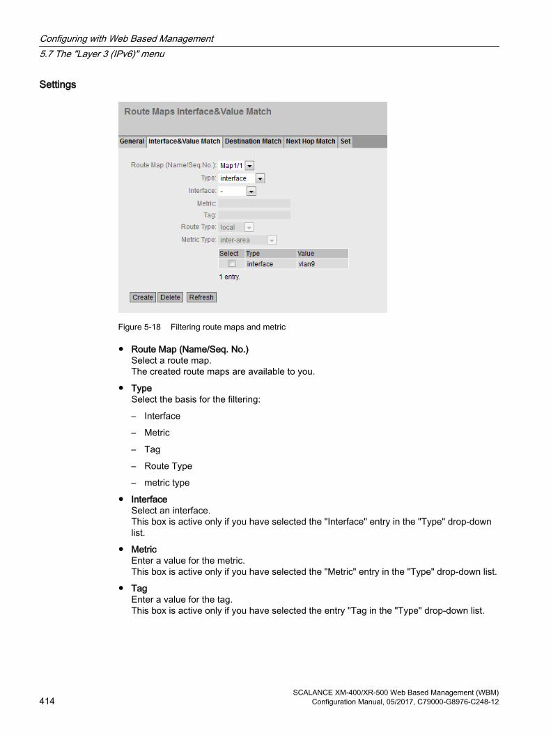
Settings
Figure 5-18 Filtering route maps and metric
● Route Map (Name/Seq. No.)Select a route map.The created route maps are available to you.
● TypeSelect the basis for the filtering:
– Interface
– Metric
– Tag
– Route Type
– metric type
● InterfaceSelect an interface.This box is active only if you have selected the "Interface" entry in the "Type" drop-down list.
● MetricEnter a value for the metric.This box is active only if you have selected the "Metric" entry in the "Type" drop-down list.
● TagEnter a value for the tag.This box is active only if you have selected the entry "Tag in the "Type" drop-down list.
Configuring with Web Based Management5.7 The "Layer 3 (IPv6)" menu
SCALANCE XM-400/XR-500 Web Based Management (WBM)414 Configuration Manual, 05/2017, C79000-G8976-C248-12

● Route TypeSelect the type of the route.
– LocalThe routing information for the route map is filtered according to directly connected routes (local interfaces).
– RemoteThe routing information for the route map is filtered according to learned or statically configured routes.
This box is active only if you have selected the entry "Route Type in the "Type" drop-down list.
● metric typeSelect the type of the metric.
– inter-areaThe routing information for the route map is filtered according to routes learned from other areas.
– intra-areaThe routing information for the route map is filtered according to routes originating from the same area.
– type-1-externalThe routing information for the route map is filtered according to routes whose path costs (metric) are made up of the external path costs and the path costs to the ASBR.
– type-2-externalThe routing information for the route map is filtered according to routes with only external path costs (netric).
This box is active only if you have selected the entry "Metric Type" in the "Type" drop-down list.
The table has the following columns:
● SelectSelect the row you want to delete.
● TypeShows the selected type:
– Interface
– Metric
– Tag
– Route Type
– metric type
● ValueShows the selected interface or the value of the metric or of the tag.
Configuring with Web Based Management5.7 The "Layer 3 (IPv6)" menu
SCALANCE XM-400/XR-500 Web Based Management (WBM)Configuration Manual, 05/2017, C79000-G8976-C248-12 415

5.7.5.3 Destination MatchOn this page, you specify whether or not the routing information for a route map is filtered based on the destination IP address.
Settings● Route Map (Name/Seq. No.)
Select a route map.
● IP AddressEnter the IPv6 address of the destination on which the filtering is based.
● Prefix LengthEnter the number of left-hand bits belonging to the prefix
The table has the following columns:
● SelectSelect the check box in the row to be deleted.
● IP AddressShows the IPv6 address of the destination.
● Prefix LengthShows the prefix length.
5.7.5.4 Next-Hop filternOn this page, you specify whether or not the filtering for a route map will be based on the router to which the routing information is sent next.
Configuring with Web Based Management5.7 The "Layer 3 (IPv6)" menu
SCALANCE XM-400/XR-500 Web Based Management (WBM)416 Configuration Manual, 05/2017, C79000-G8976-C248-12

Settings
Figure 5-19 Route Maps Next Hop Match
● Route Map (Name/Seq. No.)Select a route map.
● IP AddressEnter the IP address of the router to which the routing information will be sent next.
The table has the following columns:
● SelectSelect the row you want to delete.
● IP AddressShows the IP address of the next router.
5.7.5.5 EinstellenOn this page, you specify whether or not the routing information will be changed by a route map.
You can only change the information of a "Permit" route map.
If, for example, you have filtered based on a certain metric, you can change the value of the metric here. The routing information is then forwarded with the new value.
Configuring with Web Based Management5.7 The "Layer 3 (IPv6)" menu
SCALANCE XM-400/XR-500 Web Based Management (WBM)Configuration Manual, 05/2017, C79000-G8976-C248-12 417
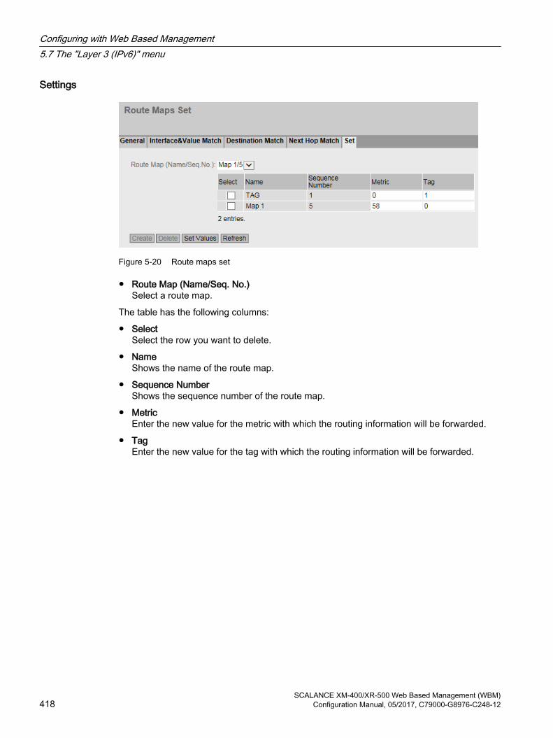
Settings
Figure 5-20 Route maps set
● Route Map (Name/Seq. No.)Select a route map.
The table has the following columns:
● SelectSelect the row you want to delete.
● NameShows the name of the route map.
● Sequence NumberShows the sequence number of the route map.
● MetricEnter the new value for the metric with which the routing information will be forwarded.
● TagEnter the new value for the tag with which the routing information will be forwarded.
Configuring with Web Based Management5.7 The "Layer 3 (IPv6)" menu
SCALANCE XM-400/XR-500 Web Based Management (WBM)418 Configuration Manual, 05/2017, C79000-G8976-C248-12

5.7.6 DHCPv4 Relay Agent
5.7.6.1 InterfacesA DHCPv6 relay agent forwards the DHCP queries of the DHCPv6 client to the DHCPv6 server. When forwarding the remote ID is inserted in the DHCP query. The remote ID is the identifier of the interface. With this, the DHCPv6 relay agent can send the reply of the DHCPv6 server to the required DHCPv6 client.
DescriptionThe page contains the following boxes:
● Remote ID (Opt. 37)When enabled the DHCP relay agent option 37 (Remote ID) is used. Specify the type of identifier in "Remote ID Type".
● InterfaceSelect the IPv6 interface.
The table has the following columns:
● SelectSelect the row you want to delete.
● InterfaceInterface to which the settings relate.
● Current Remote IDShows which remote ID is currently being used.
Configuring with Web Based Management5.7 The "Layer 3 (IPv6)" menu
SCALANCE XM-400/XR-500 Web Based Management (WBM)Configuration Manual, 05/2017, C79000-G8976-C248-12 419

● Remote ID TypeSelect hat is used as the identifier for the IPv6 interface. The following options are available:
– DUIDDHCP Unique Identifier
– System NameSystem name of the device
– Management IPManagement IPv6 address of the device
– User DefinedUser-defined entry
● DHCP Unique IdentifierEnter the DUID (DHCP Unique Identifier).
● User DefinedEnter a user-defined entry as the identifier.
Steps in configuration1. Enable Remote ID (Opt. 37).
2. Select the required interface and click the "Set Values" button.
3. Click the "Create" button. A new entry is generated in the table.
4. Specify the type of remote ID in "Remote ID Type" e.g. the system name. The system name of the device is used as the identifier.
5.7.6.2 Server AddressesOn this page you enable the DHCPv6 relay agent on the interface. You also specify which DHCPv6 server can be reached via it.
Configuring with Web Based Management5.7 The "Layer 3 (IPv6)" menu
SCALANCE XM-400/XR-500 Web Based Management (WBM)420 Configuration Manual, 05/2017, C79000-G8976-C248-12
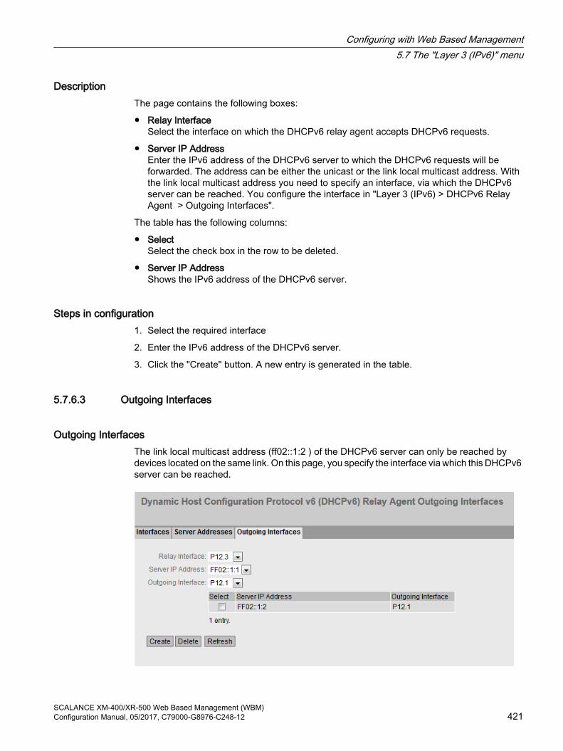
DescriptionThe page contains the following boxes:
● Relay InterfaceSelect the interface on which the DHCPv6 relay agent accepts DHCPv6 requests.
● Server IP AddressEnter the IPv6 address of the DHCPv6 server to which the DHCPv6 requests will be forwarded. The address can be either the unicast or the link local multicast address. With the link local multicast address you need to specify an interface, via which the DHCPv6 server can be reached. You configure the interface in "Layer 3 (IPv6) > DHCPv6 Relay Agent > Outgoing Interfaces".
The table has the following columns:
● SelectSelect the check box in the row to be deleted.
● Server IP AddressShows the IPv6 address of the DHCPv6 server.
Steps in configuration1. Select the required interface
2. Enter the IPv6 address of the DHCPv6 server.
3. Click the "Create" button. A new entry is generated in the table.
5.7.6.3 Outgoing Interfaces
Outgoing InterfacesThe link local multicast address (ff02::1:2 ) of the DHCPv6 server can only be reached by devices located on the same link. On this page, you specify the interface via which this DHCPv6 server can be reached.
Configuring with Web Based Management5.7 The "Layer 3 (IPv6)" menu
SCALANCE XM-400/XR-500 Web Based Management (WBM)Configuration Manual, 05/2017, C79000-G8976-C248-12 421

DescriptionThe page contains the following boxes:
● Relay InterfaceSelect the IPv6 interface on which the DHCPv6 relay agent accepts DHCPv6 requests.
● Server IP AddressSelect the IPv6 address of the DHCPv6 server.
● Outgoing InterfaceSelect the IPv6 interface via which the DHCPv6 server can be reached.
The table has the following columns:
● SelectSelect the check box in the row to be deleted.
● Server IP AddressShows the IPv6 address of the DHCPv6 server.
● Outgoing InterfaceShows the IPv6 interface via which the DHCPv6 server can be reached.
5.7.7 VRRPv3
5.7.7.1 Routers
Introduction Using the "Create" button, you can create new virtual routers. A maximum of 52 Virtual routers can be configured. You can configure other parameters on the "Configuration" tab.
Note● This function is available only with layer 3.● Simultaneous operation of VRRP and VRRPv3 is not possible.● Select the "VRRPv3" check box to configure VRRPv3.● You can use VRRPv3 on VLAN interfaces. Router ports are not supported.
Configuring with Web Based Management5.7 The "Layer 3 (IPv6)" menu
SCALANCE XM-400/XR-500 Web Based Management (WBM)422 Configuration Manual, 05/2017, C79000-G8976-C248-12

DescriptionThe page contains the following:
● VRRPv3Enable or disable routing using VRRPv3. Can only be enabled when "Layer 3 (IPv6) > Configuration" "IPv6 Routing" is enabled.
● VRID-TrackingEnable or disable VRID tracking.When enabled, all interfaces of a VRID are monitored. When the link of an interface changes from "up" to "down", the priority of all VRRP interfaces with the same VRID is reduced to the value "0".When the link of an interface changes back from "down" to "up", the original priority of the VRRP interfaces is restored.
● InterfaceSelect the required VLAN interface operating as virtual router.
● VRIDEnter the ID of the virtual router. This ID defines the group of routers that form a virtual router (VR). In the group, this is the same. It can no longer be used for other groups.Valid values are 1.. 255.
The table has the following columns:
● SelectSelect the check box in the row to be deleted.
● InterfaceShows the Interface that functions as the virtual router.
● VRIDShows the ID of the virtual router.
● Virtual MAC AddressShows the virtual MAC address of the virtual router.
● Primary IP AddressShows the numerically lowest IPv6 address in this VLAN. The entry "::" means that the "Primary" address on this VLAN is used. Otherwise all IPv6 addresses configured on this VLAN in the "Layer 3 (IPv6) > Subnets" menu are valid values.
Configuring with Web Based Management5.7 The "Layer 3 (IPv6)" menu
SCALANCE XM-400/XR-500 Web Based Management (WBM)Configuration Manual, 05/2017, C79000-G8976-C248-12 423

● Router State Shows the current status of the virtual router. Possible values are:
– MasterThe router is the master router and handles the routing functionality for all assigned IPv4 addresses.
– BackupThe router is the backup router. If the master router fails, the backup router takes over the tasks of the master router.
– InitializeThe virtual router has just been turned on. It will soon change to the "Master" or "Backup" state.
● Master IP AddressShows the IPv6 address of the master router.
● PriorityShows the priority of the virtual router.Valid values are 1-254. The current master router is automatically given 255. All other priorities can be distributed freely among the VRRPv3 routers. The higher the priority, the earlier the VRRPv3 router becomes "Master".
● Advert. InternalShows the interval at which the master router sends VRRPv3 packets.
● PreemptShows the precedence of a router when changing roles between backup and master.
– yesThis router has precedence when changing roles.
– noThis router does not have precedence when changing roles.
● Accept ModeShows the precedence of a router when changing roles between backup and master.
– YesVirtual IP addresses also reply to pings.
– NoVirtual IP addresses do not reply to pings.
VRRP and DHCP serverIf you want to operate a DHCP server on the devices of a VRRP group, the DHCP server must be configured on the master router. Backup routers do not react to DHCP queries. Make sure that the master router is statically configured and that after a failure, becomes the master of the VRRP group again.
Steps in configuration1. Select the "VRRPv3" check box.
2. Select the required interface.
Configuring with Web Based Management5.7 The "Layer 3 (IPv6)" menu
SCALANCE XM-400/XR-500 Web Based Management (WBM)424 Configuration Manual, 05/2017, C79000-G8976-C248-12

3. Enter the ID of the virtual router in the "VRID" input box.
4. Click the "Create" button. A new row is inserted in the table.
5. Select the "VRID Tracking" check box to monitor the VRID.
6. Click the "Set Values" button. To configure the virtual router, click on the "Configuration" tab.
5.7.7.2 Configuration
IntroductionOn this page, you configure the virtual router.
Note
This function is available only with layer 3.
Configuring with Web Based Management5.7 The "Layer 3 (IPv6)" menu
SCALANCE XM-400/XR-500 Web Based Management (WBM)Configuration Manual, 05/2017, C79000-G8976-C248-12 425

DescriptionThe page contains the following:
● Interface / VRIDSelect the ID of the virtual router to be configured.
● Primary AddressSelect the primary IPv6 address. If the router becomes master router, the router uses this IPv4 address.
Note
If you only configure one subnet on this VLAN, no entry is necessary. The entry is then ::. If you configure more than one subnet on the VLAN and you want a specific IPv6 address to be used as the source address for VRRP packets, select the IPv6 address. Otherwise, the IPv6 address with priority will be used.
● MasterIf enabled, the primary IPv6 address is entered for "Associated IP Address". This means that the highest priority IPv6 address of the VRRP router is used as the virtual IP address of the virtual master router. The backup routers in this group must disable the option and use the IPv6 address of the router in "Associated IP address".
● PriorityEnter the priority of this virtual router. Valid values are 1-254. The current master router is always given 255. All other priorities can be distributed freely among the redundant routers. The higher the priority, the earlier the router becomes "Master".
● Advertisement intervalEnter the interval in seconds after which a master router sends a VRRPv3 packet again.
● Preempt lower priority Master.Allow precedence when changing roles between backup and master based on the selection process.
● Reply to pings on virtual interfaces (Accept Mode)When enabled, the virtual IPv6 addresses also reply to the ping.
● Track IDSelect a track ID.
● Decrement PriorityEnter the value by which the priority of the VRRPv3 interface will be reduced.
● Current PriorityShows the priority of the VRRPv3 interface after the monitored interface has changed to the "down" status.
Steps in configurationTo configure a virtual router as the master router, follow the steps below:
1. Select the ID of the virtual router you want to configure from the "Interface / VRID" drop-down list.
2. Select the "Status" check box.
Configuring with Web Based Management5.7 The "Layer 3 (IPv6)" menu
SCALANCE XM-400/XR-500 Web Based Management (WBM)426 Configuration Manual, 05/2017, C79000-G8976-C248-12
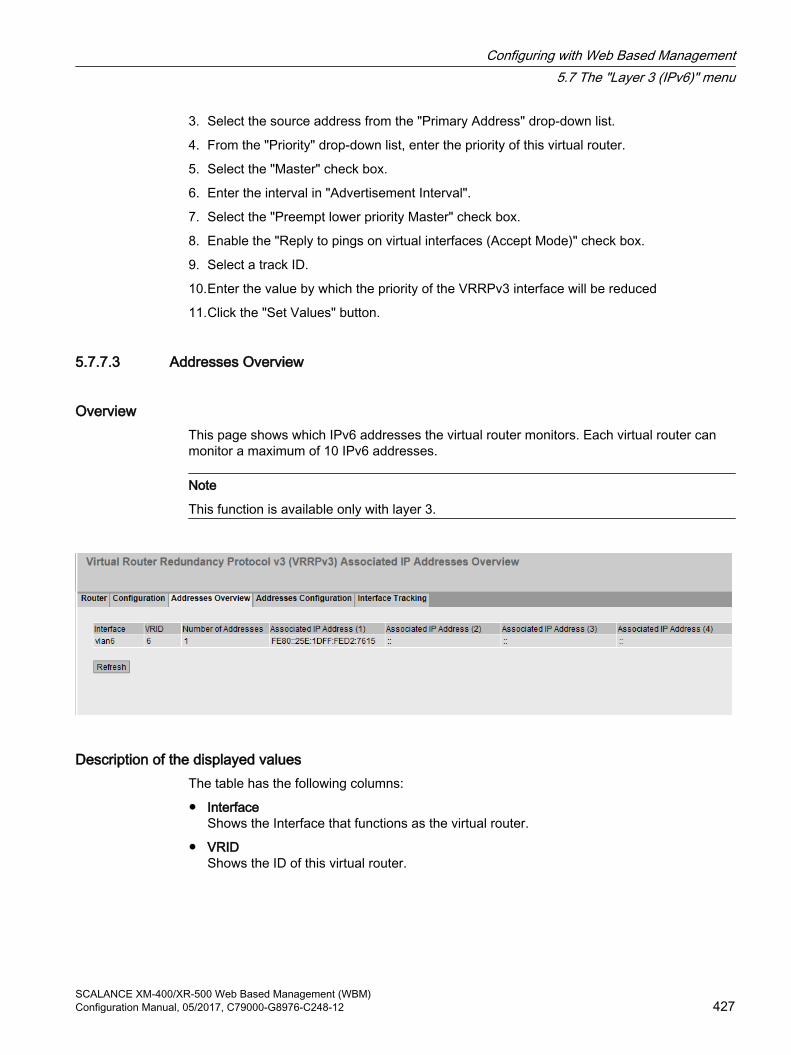
3. Select the source address from the "Primary Address" drop-down list.
4. From the "Priority" drop-down list, enter the priority of this virtual router.
5. Select the "Master" check box.
6. Enter the interval in "Advertisement Interval".
7. Select the "Preempt lower priority Master" check box.
8. Enable the "Reply to pings on virtual interfaces (Accept Mode)" check box.
9. Select a track ID.
10.Enter the value by which the priority of the VRRPv3 interface will be reduced
11.Click the "Set Values" button.
5.7.7.3 Addresses Overview
OverviewThis page shows which IPv6 addresses the virtual router monitors. Each virtual router can monitor a maximum of 10 IPv6 addresses.
Note
This function is available only with layer 3.
Description of the displayed valuesThe table has the following columns:
● InterfaceShows the Interface that functions as the virtual router.
● VRIDShows the ID of this virtual router.
Configuring with Web Based Management5.7 The "Layer 3 (IPv6)" menu
SCALANCE XM-400/XR-500 Web Based Management (WBM)Configuration Manual, 05/2017, C79000-G8976-C248-12 427

● Number of AddressesShows the number of IPv6 addresses.
● Associated IP Address (1) ...Associated IP Address (10)Shows the router IPv6 addresses monitored by this virtual router. If a router takes over the role of master, the routing function is taken over by this router for all these IPv6 addresses.
5.7.7.4 Addresses Configuration
Creating or changing the monitored IP addressesOn this page, you can create, modify or delete the IPv4 addresses to be monitored. A maximum of 10 IPv4 addresses can be monitored by a virtual router.
Note
This function is available only with layer 3.
DescriptionThe page contains the following:
● Interface / VRIDSelect the ID of the virtual router.
● Associated IP AddressEnter the IPv6 address that the virtual router will monitor. A maximum of 10 IPv6 addresses are possible.
The table has the following columns:
● SelectSelect the check box in the row to be deleted
● Associated IP AddressShows the IPv6 addresses that the virtual router monitors.
Configuring with Web Based Management5.7 The "Layer 3 (IPv6)" menu
SCALANCE XM-400/XR-500 Web Based Management (WBM)428 Configuration Manual, 05/2017, C79000-G8976-C248-12
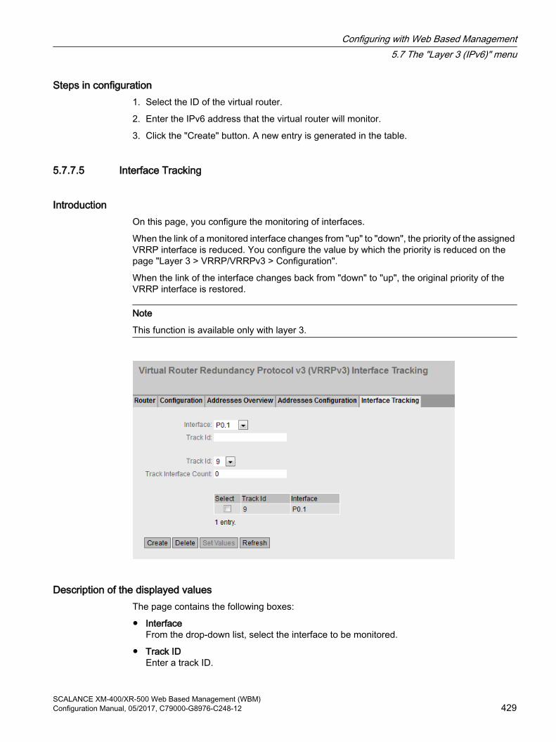
Steps in configuration1. Select the ID of the virtual router.
2. Enter the IPv6 address that the virtual router will monitor.
3. Click the "Create" button. A new entry is generated in the table.
5.7.7.5 Interface Tracking
IntroductionOn this page, you configure the monitoring of interfaces.
When the link of a monitored interface changes from "up" to "down", the priority of the assigned VRRP interface is reduced. You configure the value by which the priority is reduced on the page "Layer 3 > VRRP/VRRPv3 > Configuration".
When the link of the interface changes back from "down" to "up", the original priority of the VRRP interface is restored.
Note
This function is available only with layer 3.
Description of the displayed valuesThe page contains the following boxes:
● InterfaceFrom the drop-down list, select the interface to be monitored.
● Track IDEnter a track ID.
Configuring with Web Based Management5.7 The "Layer 3 (IPv6)" menu
SCALANCE XM-400/XR-500 Web Based Management (WBM)Configuration Manual, 05/2017, C79000-G8976-C248-12 429

● Track IDSelect a track ID.
● Track Interface CountEnter how many monitored interfaces need to change to the "down" status, before the priority is changed.
The table has the following columns:
● SelectSelect the check box in the row to be deleted.
● Track IDShows the track ID.
● InterfaceShows the interface that is being monitored.
Steps in configuration1. Select the required interface from the "Interface" drop-down list.
2. In the "Track ID" box, enter the required ID.
3. Click the "Create" button.
4. Select an ID from the "Track-ID" drop-down list:
5. In the "Track Interface Count" enter the number of interfaces.
6. Click the "Set Values" button.
7. Link the monitoring to a VRRP interface in the "Configuration" tab.
5.7.8 OSPFv3
5.7.8.1 Configuration
Introduction On this page, you configure the routing using OSPFv3.
Note
This function is available only with layer 3.
Configuring with Web Based Management5.7 The "Layer 3 (IPv6)" menu
SCALANCE XM-400/XR-500 Web Based Management (WBM)430 Configuration Manual, 05/2017, C79000-G8976-C248-12

DescriptionThe page contains the following boxes:
● OSPFv3Enable or disable routing using OSPFv3.
● Router IDEnter the designation of the OSPFv3 interfaces. The router ID is specified in IPv4 format and must be unique in the network.
● Border RouterDisplays the status of the OSPFv3 router. If the local system is an active member in at least 2 areas, this is an area border router.
● AS Border RouterSpecify whether the router is an AS border router. An AS border router intercedes between multiple autonomous systems, for example if you have an additional RIP network. An AS border router is also necessary to add and to distribute static routes.
● New LSA ReceivedShows the number of received LSAs. Updates and its own LSAs are not counted.
● New LSA ConfiguredShows the number of different LSAs sent by this local system.
● External LSA MaximumTo limit the number of entries of external LSAs in the database, enter the maximum number of external LSAs.
Configuring with Web Based Management5.7 The "Layer 3 (IPv6)" menu
SCALANCE XM-400/XR-500 Web Based Management (WBM)Configuration Manual, 05/2017, C79000-G8976-C248-12 431

● Exit Interval [s]Enter the interval after which the OSPFv3 router once again attempts to come out of the overflow status. A 0 means that the OSPFv3 router attempts to exit the overflow status only following a restart.
● Inbound FilterSelect a route map that filters inbound routes.
● Redistribute RoutesSpecify which known routes are distributed using OSPFv3. You make different decisions for the route types Connected, Static and RIPng.
Note
The options can only be enabled on an AS border router. Enabling the Default and Static options, in particular, can cause problems if they are enabled at too many points in the network, for example, forwarding loops.
● Route MapSelect a route map that filters which routes are forwarded using RIPng.
Steps in configuration1. Select the "OSPFv3" check box.
2. Enter the ID of the router in the "Router ID" input box.
3. Select the "AS Border Router" check box.
4. Click the "Set Values" button.
5.7.8.2 Areas
OverviewAn autonomous system can be divided into smaller areas.
On this page, you can view, create, modify or delete the areas of the router.
Note
This function is available only with layer 3.
Configuring with Web Based Management5.7 The "Layer 3 (IPv6)" menu
SCALANCE XM-400/XR-500 Web Based Management (WBM)432 Configuration Manual, 05/2017, C79000-G8976-C248-12

DescriptionThe page contains the following:
● Area IDEnter the designation of the area. The database is synchronized for all routers of an area. The area identifier must be unique in the network.The area identifier is a 32-bit number with the following format: x.x.x.x where x = 0 ... 255The area identifier 0.0.0.0 is reserved for the backbone area and cannot be deleted.
This table contains the following columns:
● SelectSelect the check box in the row to be deleted.
● Area IDShows the designation of the area.
● Area TypeSpecify the type of area.
– Normal
– Stub
– NSSA
– Backbone
● SummarySpecify whether summary LSAs are generated for this area.
– Summary: Summary LSAs are generated and sent to the area.
– No Summary: Summary LSAs are not generated and sent to the area.
● MetricDisplays the costs for the OSPFv3 interface.
● UpdatesShows the number of recalculations of the routing tables.
Configuring with Web Based Management5.7 The "Layer 3 (IPv6)" menu
SCALANCE XM-400/XR-500 Web Based Management (WBM)Configuration Manual, 05/2017, C79000-G8976-C248-12 433

● LSA CountShows the number of LSAs in the database.
● Area BRShows the number of reachable area border routers (ABR) within this area.
● AS BRShows the number of reachable autonomous system border routers (ASBR) in this area.
Steps in configuration1. Enter the ID for the area in the "Area ID" input box.
2. Click the "Create" button. A new entry is generated in the table.
3. Select the type of area, for example Stub in the "Area Type" drop-down list.
4. Select the "Summary LSA" entry in the "Summary" drop-down list.
5. Click the "Set Values" button.
5.7.8.3 Area
Creating a new OSPFv3 area range . On this page, you can group up to 4 networks under one area ID. The method is used only with area border routers. This means that an area border router only advertises one route for grouped areas to the outside.
Note
This function is available only with layer 3.
Configuring with Web Based Management5.7 The "Layer 3 (IPv6)" menu
SCALANCE XM-400/XR-500 Web Based Management (WBM)434 Configuration Manual, 05/2017, C79000-G8976-C248-12

DescriptionThe page contains the following boxes:
● Area IDSelect the area ID of the area. You specify the ID on the "Areas" tab.
● PrefixEnter the IPv6 address of the network that will be grouped.
● Prefix LengthEnter the number of bits belonging to the prefix that will be grouped.
This table contains the following columns:
● SelectSelect the check box in the row to be deleted.
● Area IDShows the ID of the area.
● PrefixShows the IPv6 address of the network that will be grouped.
● Prefix LengthEnter the number of bits that will belong to the prefix.
● AdvertiseEnable this option to advertise the grouped network.
Steps in configuration1. Select the area ID of the area.
2. Enter the prefix of the network that will be grouped.
3. Enter the prefix length of the network that will be grouped.
4. Click the "Create" button. A new entry is generated in the table.
5. Enable the "Advertise" option to advertise the grouped network.
6. Click the "Set Values" button.
5.7.8.4 Interfaces
OverviewOn this page, you can configure OSPFv3 interfaces.
Note
This function is available only with layer 3.
Configuring with Web Based Management5.7 The "Layer 3 (IPv6)" menu
SCALANCE XM-400/XR-500 Web Based Management (WBM)Configuration Manual, 05/2017, C79000-G8976-C248-12 435

DescriptionThe page contains the following:
● InterfaceSelect the IPv6 interface on which OSPFv3 will be enabled.
● Area IDSelect the area ID of the area with which the OSPFv3 interface is connected.
Note
For the secondary interface select the same Area ID as for the corresponding primary interface. The information whether a primary or secondary interface is involved can be found in "Layer 3 (IPv6) > Subnets".
This table contains the following columns:
● SelectSelect the check box in the row to be deleted.
● InterfaceShows the OSPFv3 interface.
● Area IDSelect the area ID of the area with which the OSPFv3 interface is connected.
● Passive InterfaceSpecify the behavior of the interface:
– Enabled: No OSPFv3 information (e.g. Hello frames and LSDB updates) is sent via this interface and learned.
– Disabled: OSPFv3 information is sent and learned via this interface.
● MetricEnter the costs for the OSPFv3 interface.
Configuring with Web Based Management5.7 The "Layer 3 (IPv6)" menu
SCALANCE XM-400/XR-500 Web Based Management (WBM)436 Configuration Manual, 05/2017, C79000-G8976-C248-12

● PriorityEnter the router priority. The priority is only relevant for selecting the designated router or designated border router. This parameter can be selected differently on routers within the same subnet. Range of values: 0 to 255 Default: 1.
● Trans. DelayEnter the required delay when sending a connection update.Range of values: 1 s to 3600 sDefault: 1 s
● Retrans. Interval Enter the time after which an OSPFv3 packet is transferred again if no confirmation was received.Range of values: 1 s to 3600 sDefault: 5 s
● Hello IntervalEnter the interval between two Hello packets.Range of values: 1 s to 65,535 sDefault: 10 s
● Dead IntervalEnter the interval after which the neighbor router is marked as "failed" if no more Hello packets are received from it during this time.Default: 60 s
Steps in configuration1. Select the required interface. The interface is configured as an OSPFv3 Interface
2. Select the area ID of the area with which the OSPFv3 interface is connected.
3. Click the "Create" button. A new entry is generated in the table.
4. Make the required settings or use the factory defaults.
5. Click the "Set Values" button.
5.7.8.5 Virtual Links
Overview Due to the protocol, each area border router must have access to the backbone area. If a router is not connected directly to the backbone area, a virtual link to it is created.
Note
This function is available only with layer 3.
Configuring with Web Based Management5.7 The "Layer 3 (IPv6)" menu
SCALANCE XM-400/XR-500 Web Based Management (WBM)Configuration Manual, 05/2017, C79000-G8976-C248-12 437

Note
Note that when creating a virtual link both the transit area and the backbone area must already be configured.
A virtual link must be configured identically at both ends.
Description The page contains the following:
● Neighbor Router IDEnter the ID of the neighbor router at the other end of the virtual connection.
● Transit Area ID
● Select the ID of the area that connects the two routers.
This table contains the following columns:
● SelectSelect the check box in the row to be deleted.
● Transit Area IDShows the ID via which the two routers are connected.
● Neighbor Router IDShows the ID of the neighbor router at the other end of the virtual connection.
● Virt. Link StatusSpecify the status of the virtual link. The following states are possible:
– down: The virtual link is inactive.
– point-to-point: The virtual link is active.
● Trans. DelayEnter the required delay when sending a connection update.Range of values: 1 s to 3600 sDefault: 1 s
Configuring with Web Based Management5.7 The "Layer 3 (IPv6)" menu
SCALANCE XM-400/XR-500 Web Based Management (WBM)438 Configuration Manual, 05/2017, C79000-G8976-C248-12

● Retrans. Interval Enter the time after which a packet is transferred again if no confirmation was received.Range of values: 1 s to 3600 sDefault: 5 s
● Hello IntervalEnter the interval between two Hello packets.Range of values: 1 s to 65,535 sDefault: 10 s
● Dead IntervalEnter the interval after which the neighbor router counts as "failed" if no more Hello packets are received from it during this time. Default setting: 60 s
Steps in configuration1. Enter the ID of the neighbor router at the other end of the virtual link.
2. Select the area ID that connects the two routers.
3. Click the "Create" button. A new entry is generated in the table.
4. Enter suitable values in "Trans. Delay", "Retrans. Interval" and "Dead Interval".
5. Click the "Set Values" button.
5.7.9 RIPng
5.7.9.1 RIPng ConfigurationOn this page, you configure routing with RIPng.
Note
RIPng is available only on layer 3.
Configuring with Web Based Management5.7 The "Layer 3 (IPv6)" menu
SCALANCE XM-400/XR-500 Web Based Management (WBM)Configuration Manual, 05/2017, C79000-G8976-C248-12 439

Settings
● Inbound FilterSelect a route map that filters inbound routes.
● Redistribute RoutesSpecify which known routes are distributed using RIPv2.The following types of route exist:
– Connected
– Static
– OSPFv3
● Route MapSelect a route map that filters which routes are forwarded using RIPng.
5.7.9.2 RIPng interfaces
OverviewOn this page, you specify the interfaces that support RIPng.
Figure 5-21 RIPv2 Interfaces
Configuring with Web Based Management5.7 The "Layer 3 (IPv6)" menu
SCALANCE XM-400/XR-500 Web Based Management (WBM)440 Configuration Manual, 05/2017, C79000-G8976-C248-12
Note
RIPng is available only on layer 3.
Description This table contains the following columns:
● InterfaceShows the available IPv6 interface.
● Admin StateEnable or disable the RIPng routing for the interface.
● Default MetricEnter the costs for the RIPng interface.
5.8 The "Security" menu
5.8.1 User management
Overview of user managementAccess to the device is managed by configurable user settings. Set up users with a password for authentication. Assign a role with suitable rights to the users.
The authentication of users can either be performed locally by the device or by an external RADIUS server. You configure how the authentication is handled on the "Security > AAA > General" page.
Note
When you transfer the configuration of a device to STEP 7 (TIA Portal), the configured users, roles and groups are not transferred.
Compatibility with predecessor versionsWith firmware version 5.1, user management was expanded by the RADIUS authorization mode "Vendor Specific". To ensure compatibility with firmware versions ≤ 5.0, the default setting was selected so that following a firmware update the earlier authentication mode "conventional" continues to be used.
Configuring with Web Based Management5.8 The "Security" menu
SCALANCE XM-400/XR-500 Web Based Management (WBM)Configuration Manual, 05/2017, C79000-G8976-C248-12 441

Local logonThe local logging on of users by the device runs as follows:
1. The user logs on with user name and password on the device.
2. The device checks whether an entry exists for the user.→ If an entry exists, the user is logged in with the rights of the associated role.→ If no corresponding entry exists, the user is denied access.
Login via an external RADIUS serverRADIUS(Remote Authentication Dial-In User Service) is a protocol for authenticating and authorizing users by servers on which user data can be stored centrally.
Depending on the RADIUS authorization mode you have selected on the "Security > AAA > RADIUS Client" page, the device evaluates different information of the RADIUS server.
RADIUS authorization mode "Standard"If you have set the authorization mode "conventional", the authentication of users via a RADIUS server runs as follows:
1. The user logs on with user name and password on the device.
2. The device sends an authentication request with the login data to the RADIUS server.
3. The RADIUS server runs a check and signals the result back to the device.
– The RADIUS server reports a successful authentication and for the "Service Type" attribute returns the value "Administrative User" to the device→ The user is logged in with read/write rights.
– The RADIUS server reports a successful authentication and returns a different or even no value to the device for the attribute "Service Type".→ The user is logged in with read rights.
– The RADIUS server reports a failed authentication to the device:→ The user is denied access.
RADIUS authorization mode "Vendor Specific"Requirement
For the RADIUS authorization mode "Vendor Specific" the following needs to be set on the RADIUS server:
● Manufacturer code: 4196
● Attribute number: 1
● Attribute format: Character string (group name)
Procedure
Configuring with Web Based Management5.8 The "Security" menu
SCALANCE XM-400/XR-500 Web Based Management (WBM)442 Configuration Manual, 05/2017, C79000-G8976-C248-12
If you have set the authorization mode "Vendor Specific", the authentication of users via a RADIUS server runs as follows:
1. The user logs on with user name and password on the device.
2. The device sends an authentication request with the login data to the RADIUS server.
3. The RADIUS server runs a check and signals the result back to the device.Case A: The RADIUS server reports a successful authentication and returns the group assigned to the user to the device.
– The group is known on the device and the user is not entered in the table "External User Accounts"→ The user is logged in with the rights of the assigned group.
– The group is known on the device and the user is entered in the table "External User Accounts"→ The user is assigned the role with the higher rights and logged in with these rights.
– The group is not known on the device and the user is entered in the table "External User Accounts"→ The user is logged in with the rights of the role linked to the user account.
– The group is not known on the device and the user is not entered in the table "External User Accounts"→ The user is logged in with the rights of the role "Default".
Case B: The RADIUS server reports a successful authentication but does not return a group to the device.
– The user is entered in the table "External User Accounts":→ The user is logged in with the rights of the linked role "".
– The user is not entered in the table "External User Accounts":→ The user is logged in with the rights of the role "Default".
Case C: The RADIUS server reports a failed authentication to the device:
– The user is denied access.
Assignment of a VLAN via RADIUS or guest VLANAuthentication with a change to the VLAN configuration
Configuring with Web Based Management5.8 The "Security" menu
SCALANCE XM-400/XR-500 Web Based Management (WBM)Configuration Manual, 05/2017, C79000-G8976-C248-12 443

If during authentication a port is assigned to a VLAN dynamically using the function "RADIUS VLAN Assignment Allowed" or "Guest VLAN" the options are as follows:
● If the VLAN that is to be assigned has not been created on the device, the authentication is rejected.
● If the VLAN that is to be assigned has been created on the device:
– The port becomes an untagged member in the assigned VLAN if it was not already.→ This makes it possible for the static configuration of the port in this VLAN to be overwritten and not restored if the authentication is retracted.
– The port VID of the port is changed to the ID of the assigned VLAN.
Note
If the port is only to be assigned to one VLAN, you need to adapt the VLAN configuration manually. As default, all ports are untagged members in "VLAN 1".
If the authentication is canceled, e.g. by link down, the dynamic changes are canceled.
● The port is no longer a member in the assigned VLAN.
● The port VID of the port is reset to the value it had prior to authentication.
Note
If the port VID corresponds to the assigned port VID prior to authentication, the port remains an untagged member in this VLAN.
Authentication without a change to the VLAN configuration
If during authentication no VLAN is assigned either by the function "RADIUS VLAN Assignment Allowed" or by "Guest VLAN", the existing VLAN configuration of the port remains unchanged.
5.8.2 Users
5.8.2.1 Local Users
Local usersOn this page, you create local users with the corresponding rights.
When you create or delete a local user this change is also made automatically in the table "External User Accounts". If you want to make change explicitly for the internal or external user table, use the CLI commands.
Note
The values displayed depend on the rights of the logged-in user.
Configuring with Web Based Management5.8 The "Security" menu
SCALANCE XM-400/XR-500 Web Based Management (WBM)444 Configuration Manual, 05/2017, C79000-G8976-C248-12

Configuring with Web Based Management5.8 The "Security" menu
SCALANCE XM-400/XR-500 Web Based Management (WBM)Configuration Manual, 05/2017, C79000-G8976-C248-12 445

DescriptionThe page contains the following:
● User AccountEnter the name for the user. The name must meet the following conditions:
– It must be unique.
– It must be between 1 and 250 characters long.
– The following characters must not be included: § ? " ; :The characters for Space and Delete must also not be included.
NoteUser name cannot be changed
After creating a user, the user name can no longer be modified.
If a user name needs to be changed, the user must be deleted and a new user created.
Note
Default user "user" set in the factory
As of firmware version 6.0 the default user set in the factory "user" is no longer available when the product ships.
If you update a device to the firmware V6.0 the default user set in the factory "user" is initially still available. If you reset the device to the factory settings ("Restore Factory Defaults and Restart") the default user set in the factory "user" is deleted.
You can create new users with the role "user".
● Password PolicyShows which password policy is being used.
– HighPassword length: at least 8 characters, maximum 128 charactersAt least 1 uppercase letterAt least 1 special characterAt least 1 number
– LowPassword length: at least 6 characters, maximum 128 characters
You configure the password policy on the page "Security > Passwords > Options"".
● PasswordEnter the password. The strength of the password depends on the set password policy.
● Password ConfirmationEnter the password again to confirm it.
● RoleSelect a role.You can choose between system-defined and self-defined roles, refer to the page "Security > Users > Roles.".
Configuring with Web Based Management5.8 The "Security" menu
SCALANCE XM-400/XR-500 Web Based Management (WBM)446 Configuration Manual, 05/2017, C79000-G8976-C248-12

The table contains the following columns:
● SelectSelect the check box in the row to be deleted.
Note
The preset users as well as logged in users cannot be deleted or changed.
● User AccountShows the user name.
● RoleShows the role of the user.
● DescriptionDisplays a description of the user account. The description text can be up to 100 characters long.
ProcedureCreating users
1. Enter the name for the user.
2. Enter the password for the user.
3. Enter the password again to confirm it.
4. Select the role of the user.
5. Click the "Create" button.
6. Enter a description of the user.
7. Click the "Set Values" button.
Deleting users
1. Select the check box in the row to be deleted.
2. Click the "Delete" button. The entries are deleted and the page is updated.
5.8.2.2 Roles
RolesOn this page, you create roles that are valid locally on the device.
Note
The values displayed depend on the rights of the logged-in user.
Configuring with Web Based Management5.8 The "Security" menu
SCALANCE XM-400/XR-500 Web Based Management (WBM)Configuration Manual, 05/2017, C79000-G8976-C248-12 447

DescriptionThe page contains the following:
● Role NameEnter the name for the role. The name must meet the following conditions:
– It must be unique.
– It must be between 1 and 64 characters long.
NoteRole name cannot be changed
After creating a role, the name of the role can no longer be changed.
If a name of a role needs to be changed, the role must be deleted and a new role created.
The table contains the following columns:
● SelectSelect the check box in the row to be deleted.
Note
Predefined roles and assigned roles cannot be deleted or modified.
● RoleShows the name of the role.
Configuring with Web Based Management5.8 The "Security" menu
SCALANCE XM-400/XR-500 Web Based Management (WBM)448 Configuration Manual, 05/2017, C79000-G8976-C248-12

● Function RightSelect the function rights of the role.
– 1Users with this role can read device parameters but cannot change them. Users with this role can change their own password.
– 15Users with this role can both read and change device parameters.
NoteFunction right cannot be changed
If you have assigned a role, you can no longer change the function right of the role.
If you want to change the function right of a role, follow the steps outlined below:1. Delete all assigned users.2. Change the function right of the role:3. Assign the role again.
● DescriptionEnter a description for the role. With predefined roles a description is displayed. The description text can be up to 100 characters long.
ProcedureCreating a role
1. Enter the name for the role.
2. Click the "Create" button.
3. Select the function rights of the role.
4. Enter a description of the role.
5. Click the "Set Values" button.
Deleting a role
1. Select the check box in the row to be deleted.
2. Click the "Delete" button. The entries are deleted and the page is updated.
5.8.2.3 Groups
User GroupsOn this page you link a group with a role.
In this example the group "Administrators" is linked to the "admin"role: The group is defined on a RADIUS server. The role is defined locally on the device. When a RADIUS server
Configuring with Web Based Management5.8 The "Security" menu
SCALANCE XM-400/XR-500 Web Based Management (WBM)Configuration Manual, 05/2017, C79000-G8976-C248-12 449

authenticates a user and assigns the user to the "Administrators" group, this user is given rights of the "admin" role.
Note
The values displayed depend on the rights of the logged-in user.
DescriptionThe page contains the following:
● Group NameEnter the name of the group. The name must match the group on the RADIUS server.The name must meet the following conditions:
– It must be unique.
– It must be between 1 and 64 characters long.
The table contains the following columns:
● SelectSelect the check box in the row to be deleted.
● GroupShows the name of the group.
● RoleSelect a role. Users who are authenticated with the linked group on the RADIUS server receive the rights of this role locally on the device.You can choose between system-defined and self-defined roles, refer to the page "Security > Users > Roles.".
● DescriptionEnter a description for the link of the group.to a role. The description text can be up to 100 characters long.
ProcedureLinking a group to a role.
1. Enter the name of a group.
2. Click the "Create" button.
3. Select a role.
Configuring with Web Based Management5.8 The "Security" menu
SCALANCE XM-400/XR-500 Web Based Management (WBM)450 Configuration Manual, 05/2017, C79000-G8976-C248-12

4. Enter a description for the link of a group.to a role.
5. Click the "Set Values" button.
Deleting the link between a group and a role
1. Select the check box in the row to be deleted.
2. Click the "Delete" button. The entries are deleted and the page is updated.
5.8.3 Passwords
5.8.3.1 Passwords
Configuration of the device passwords
Note
If you are logged in via a RADIUS server, you cannot change any passwords.
On this page, you can change passwords. If you are logged on with read/write rights, you can change the passwords for all user accounts. If you are logged in with read rights, you can only change your own password.
Description of the displayed boxes● Current User
Shows the user that is currently logged in.
● Current User PasswordEnter the password for the currently logged in user.
● User AccountSelect the user whose password you want to change.
Configuring with Web Based Management5.8 The "Security" menu
SCALANCE XM-400/XR-500 Web Based Management (WBM)Configuration Manual, 05/2017, C79000-G8976-C248-12 451

● Password PolicyShows which password policy is being used when assigning new passwords.
– HighPassword length: at least 8 characters, maximum 128 charactersat least 1 uppercase letterat least 1 special characterat least 1 number
– LowPassword length: at least 6 characters, maximum 128 characters
● New PasswordEnter the new password for the selected user.The following characters must not be included:
– § ? " ; :
– The characters for Space and Delete must also not be included.
● Password ConfirmationEnter the new password again to confirm it.
Procedure
Note
When you log in for the first time or following a "Restore Factory Defaults and Restart", with the preset user "admin" you will be prompted to change the password.
The factory setting for the password when the devices ship is as follows:● admin: admin
NoteChanging the password in Trial mode
Even if you change the password in Trial mode, this change is saved immediately.
1. Enter the password for the currently logged in user in the "Current User Password" input box.
2. In the "User Account" drop-down list select the user whose password you want to change.
3. Enter the new password for the selected user in the "New Password" input box.
4. Repeat the new password in the "Password Confirmation" input box.
5. Click the "Set Values" button.
Configuring with Web Based Management5.8 The "Security" menu
SCALANCE XM-400/XR-500 Web Based Management (WBM)452 Configuration Manual, 05/2017, C79000-G8976-C248-12

5.8.3.2 OptionsOn this page you specify which password policy will be used when assigning new passwords.
Description● Password Policy
Shows which password policy is currently being used
● New Password PolicySelect the required setting from the drop-down list.
– HighPassword length: at least 8 characters, maximum 128 characters at least 1 uppercase letter at least 1 special character at least 1 number
– LowPassword length: at least 6 characters, maximum 128 characters
5.8.4 AAA
5.8.4.1 General
Login of network nodesThe designation used "AAA"" stands for "Authentication, Authorization, Accounting". This feature is used to identify and allow network nodes and to make the corresponding services available to them.
On this page, you configure the login.
Configuring with Web Based Management5.8 The "Security" menu
SCALANCE XM-400/XR-500 Web Based Management (WBM)Configuration Manual, 05/2017, C79000-G8976-C248-12 453

Description of the displayed boxesThe page contains the following boxes:
Note
To be able to use the login authentication "RADIUS", a RADIUS server must be stored and configured for user authentication.
● Login AuthenticationSpecify how the login is made:
– LocalThe authentication must be made locally on the device.
– RADIUSThe authentication must be handled via a RADIUS server.
– Local and RADIUSThe authentication is possible both with the users that exist on the device (user name and password) and via a RADIUS server.The user is first searched for in the local database. If the user does not exist there, a RADIUS request is sent.
– RADIUS and fallback LocalThe authentication must be handled via a RADIUS server.A local authentication is performed only when the RADIUS server cannot be reached in the network.
5.8.4.2 RADIUS Client
Authentication over an external serverThe concept of RADIUS is based on an external authentication server.
Each row of the table contains access data for one server. In the search order, the primary server is queried first. If the primary server cannot be reached, secondary servers are queried in the order in which they are entered.
If no server responds, there is no authentication.
Configuring with Web Based Management5.8 The "Security" menu
SCALANCE XM-400/XR-500 Web Based Management (WBM)454 Configuration Manual, 05/2017, C79000-G8976-C248-12

Description of the displayed boxesThe page contains the following boxes:
● RADIUS Authorization ModeFor the login authentication, the RADIUS authorization mode specifies how the rights are assigned to the user with a successful authentication (Page 441).
– StandardIn this mode the user is logged in with administrator rights if the server returns the value "Administrative User" to the device for the attribute "Service Type". In all other cases the user is logged in with read rights.
– Vendor SpecificIn this mode the assignment of rights depends on whether and which group the server returns for the user and whether or not there is an entry for the user in the table "External User Accounts".
The table has the following columns:
● SelectSelect the row you want to delete.
● Auth. Server TypeSelect the which authentication method the server will be used for.
– LoginThe server is used only for the login authentication.
– 802.1XThe server is used only for the 802.1X authentication.
– Login & 802.1XThe server is used for both authentication procedures.
● RADIUS Server AddressEnter the IP address, the FQDN (Fully Qualified Domain Name) or the host name of the RADIUS server.
● Server PortHere, enter the input port on the RADIUS server. As default, input port 1812 is set. The range of values is 1 to 65535.
● Shared SecretEnter your access ID here. The range of values is 1...128 characters
● Shared Secret Conf.Enter your access ID again as confirmation.
Configuring with Web Based Management5.8 The "Security" menu
SCALANCE XM-400/XR-500 Web Based Management (WBM)Configuration Manual, 05/2017, C79000-G8976-C248-12 455
● Max. Retrans.Here, enter the maximum number of retries for an attempted request.The initial connection attempt is repeated the number of times specified here before another configured RADIUS server is queried or the login counts as having failed. As default 3 retries are set, this means 4 connection attempts. The range of values is 1 to 5.
● Primary ServerUsing the options in the drop-down list, specify whether or not this server is the primary server. You can select one of the options "yes" or "no".
● TestWith this button, you can test whether or not the specified RADIUS server is available. The test is performed once and not repeated cyclically.
● Test ResultShows whether or not the RADIUS server is available:
– Failed, no test packet sentThe IP address is not reachable.The IP address is reachable, the RADIUS server is, however, not running.
– Reachable, key not acceptedThe IP address is reachable, the RADIUS server does not, however accept the specified shared secret.
– Reachable, key acceptedThe IP address is reachable, the RADIUS server accepts the specified shared secret.
The test result is not automatically updated. To delete the test result click the "Refresh" button.
Configuring with Web Based Management5.8 The "Security" menu
SCALANCE XM-400/XR-500 Web Based Management (WBM)456 Configuration Manual, 05/2017, C79000-G8976-C248-12

Steps in configurationEntering a new server
1. Click the "Create" button. A new entry is generated in the table. The following default values are entered in the table:
– Auth. Server Type: Login & 802.1X
– RADIUS Server Address: 0.0.0.0
– Server Port: 1812
– Max. Retrans.: 3
– Primary server: No
2. In the relevant row, enter the following data in the input boxes:
– Required Auth. Server Type
– RADIUS Server Address
– Server Port
– Shared Secret
– Confirm Shared Secret
– Max. Retrans.: 3
– Primary server: Yes/No
3. Click the "Set Values" button.
4. If necessary, test the reachability of the RADIUS server.
Repeat this procedure for every server you want to enter.
Modifying servers
1. In the relevant row, enter the following data in the input boxes:
– RADIUS Server Address
– Server Port
– Shared Secret
– Confirm Shared Secret
– Max. Retrans.
– Primary Server
2. Click the "Set Values" button.
3. If necessary, test the reachability of the RADIUS server.
Repeat this procedure for every server whose entry you want to modify
Configuring with Web Based Management5.8 The "Security" menu
SCALANCE XM-400/XR-500 Web Based Management (WBM)Configuration Manual, 05/2017, C79000-G8976-C248-12 457

Deleting servers
1. Click the check box in the first column before the row you want to delete to select the entry for deletion.Repeat this for all entries you want to delete.
2. Click the "Delete" button. The data is deleted from the memory of the device and the page is updated.
5.8.4.3 802.1x Authenticator
Setting up network accessAn end device can only access the network after the device has verified the login data of the device with the authentication server. The authentication can be via 802.1X or the MAC address.
When authenticating using 802.1X both the end device and the authentication server must support the EAP protocol (Extensive Authentication Protocol).
Enabling authentication for individual portsBy enabling the relevant options , you specify for each port whether or not network access protection according to IEEE 802.1X is enabled on this port.
Figure 5-22 802.1x Authenticator - first part of the table
Configuring with Web Based Management5.8 The "Security" menu
SCALANCE XM-400/XR-500 Web Based Management (WBM)458 Configuration Manual, 05/2017, C79000-G8976-C248-12

Figure 5-23 802.1X Authenticator - second part of the table
Description of the displayed boxesThe page contains the following boxes:
● MAC AuthenticationEnable or disable MAC Authentication for the device.
● Guest VLANEnable or disable the "Guest VLAN" function for the device.
Table 1 has the following columns:
● 1st columnShows that the settings are valid for all ports of table 2.
● 802.1X Auth. ControlSelect the required setting.If "No Change" is selected, the entry in table 2 remains unchanged.
● 802.1x Re-authenticationSelect the required setting.If "No Change" is selected, the entry in table 2 remains unchanged.
● MAC AuthenticationSelect the required setting.If "No Change" is selected, the entry in table 2 remains unchanged.
● RADIUS VLAN Assignment AllowedSelect the required setting.If "No Change" is selected, the entry in table 2 remains unchanged.
Configuring with Web Based Management5.8 The "Security" menu
SCALANCE XM-400/XR-500 Web Based Management (WBM)Configuration Manual, 05/2017, C79000-G8976-C248-12 459

● MAC Auth. Max Allowed AddressesSpecify how many MAC addresses can communicate on the port at the same time.If "No Change" is selected, the entry in table 2 remains unchanged.
● Guest VLANSelect the required setting.If "No Change" is selected, the entry in table 2 remains unchanged.
● Guest VLAN IDSelect the required setting.If "No Change" is selected, the entry in table 2 remains unchanged.
● Guest VLAN Max Allowed AddressesSpecify how many end devices are permitted in the "guest VLAN" on this port at the same time.If "No Change" is selected, the entry in table 2 remains unchanged.
● Copy to tableIf you click the button, the settings are adopted for all ports of table 2.
Table 2 has the following columns:
● Port This column lists all the ports available on this device.
● 802.1X Auth. ControlSpecify the authentication of the port:
– Force UnauthorizedData traffic via the port is blocked.
– Force AuthorizedData traffic via the port is allowed without any restrictions.Default setting
– AutoEnd devices are authenticated on the port with the "802.1X" method.The data traffic via the port is permitted or blocked depending on the authentication result.
● 802.1X Re-AuthenticationEnable this option if you want reauthentication of an already authenticated end device to be repeated cyclically.
● MAC AuthenticationEnable this option if you want end devices to be authenticated with the "MAC Authentication" method.If "Auto is configured for "802.1x Auth. Control and the " MAC Authentication is enabled, the timeout for the "802.1X procedure is 5 seconds. If manual input is necessary at a port for the authentication with the 802.1X" procedure, the 5 seconds may not be not adequate. To be able to run authentication using "802.1X", disable the MAC authentication on this port.
Configuring with Web Based Management5.8 The "Security" menu
SCALANCE XM-400/XR-500 Web Based Management (WBM)460 Configuration Manual, 05/2017, C79000-G8976-C248-12

● Adopt RADIUS VLAN AssignmentThe RADIUS server informs the IE switch of the VLAN to which the port will belong. Enable this option if you want the information of the server to be taken into account.The port can only be assigned to the VLAN, if the VLAN has been created on the device. Otherwise Authentication (Page 441) is rejected.If during authentication a port is assigned to a VLAN dynamically using this function, assignment using the VLAN-ID or the VLAN name is possible. Configure the following values on the RADIUS server:
– Tunnel-Type = VLAN
– Tunnel-Medium-Type = IEEE-802
– Tunnel-Private-Group-Id = VLAN-ID or VLAN-Name
The IE switch distinguishes as follows:
– VLAN ID: The RADIUS server transfers a numeric string for the parameter "Tunnel-Private-Group-Id".
– VLAN-Name: The RADIUS server transfers an alphanumeric string for the parameter "Tunnel-Private-Group-Id".
● MAC Auth. Max Permitted Addresses
– 1 - 100Specify how many MAC addresses can communicate on the port at the same time.
Note
If a device uses several MAC addresses, all MAC addresses must be authenticated. Store all the MAC addresses to be authenticated on the RADIUS server. Enter the number in the "MAC Auth. Max Permitted Addresses" box.
– 0You can set the value "0". This setting has the effect that after the first successful authentication of a MAC address, the port is released for all MAC addresses.Use caseIf you configure the value "0" for a port. connect this port to a WLAN access point. After the AP has authenticated itself successfully, all MAC addresses are released on this port. All WLAN clients connected to the AP can communicate on the port without their own authentication. Make sure that the the clients are authenticated by the AP.Firmware compatibilityIn firmware versions < 6.0.2 the value "0" is not a valid entry.If you configure the value "0" with the firmware version 6.0.2 and copy a firmware version <6.0.2 to the device, the function MAC authentication is deactivated on the relevant ports. Reconfigure the MAC authentication on these ports:
● Guest VLANEnable this option if you want the end device to be permitted in the guest VLAN if authentication fails.The port can only be assigned to the VLAN, if the VLAN has been created on the device. Otherwise Authentication (Page 441) is rejected.This function is also known as "Authentication failed VLAN".
● Guest VLAN IDEnter the VLAN ID of the guest VLANs.
Configuring with Web Based Management5.8 The "Security" menu
SCALANCE XM-400/XR-500 Web Based Management (WBM)Configuration Manual, 05/2017, C79000-G8976-C248-12 461

● Guest VLAN Max Allowed AddressesEnter how many end devices are allowed on this port in the "guest VLAN" at the same time.
● 802.1X Auth. StatusShows the status of the authentication of the port:
– Authorized
– Not Authorized
● MAC Auth. Actual Allowed AddressesShows the number of currently permitted MAC addresses.
● MAC Auth. Actual Blocked AddresesShows the number of currently blocked MAC addresses.
● Guest VLAN Actual Allowed AddressesShows how many end devices are currently allowed in the "guest VLAN".
Steps in configurationEnabling authentication for an individual port
1. Select the required options in the relevant row in table 2.
2. To apply the changes, click the "Set Values" button.
Enabling authentication for all ports
1. Select the required options in table 1.
2. Click the "Copy to table" button. The relevant settings are adopted for all ports in table 2.
3. To apply the changes, click the "Set Values" button.
Configuring with Web Based Management5.8 The "Security" menu
SCALANCE XM-400/XR-500 Web Based Management (WBM)462 Configuration Manual, 05/2017, C79000-G8976-C248-12
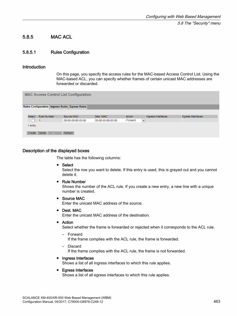
5.8.5 MAC ACL
5.8.5.1 Rules Configuration
IntroductionOn this page, you specify the access rules for the MAC-based Access Control List. Using the MAC-based ACL, you can specify whether frames of certain unicast MAC addresses are forwarded or discarded.
Description of the displayed boxesThe table has the following columns:
● SelectSelect the row you want to delete. If this entry is used, this is grayed out and you cannot delete it.
● Rule Number Shows the number of the ACL rule. If you create a new entry, a new line with a unique number is created.
● Source MACEnter the unicast MAC address of the source.
● Dest. MACEnter the unicast MAC address of the destination.
● ActionSelect whether the frame is forwarded or rejected when it corresponds to the ACL rule.
– ForwardIf the frame complies with the ACL rule, the frame is forwarded.
– DiscardIf the frame complies with the ACL rule, the frame is not forwarded.
● Ingress InterfacesShows a list of all ingress interfaces to which this rule applies.
● Egress InterfacesShows a list of all egress interfaces to which this rule applies.
Configuring with Web Based Management5.8 The "Security" menu
SCALANCE XM-400/XR-500 Web Based Management (WBM)Configuration Manual, 05/2017, C79000-G8976-C248-12 463

NoteEntering the MAC addresses
You can configure the access rules only for unicast MAC addresses.
Only if you enter the address "00:00:00:00:00:00" for the source and/or destination MAC address, the rule created in this way applies to all source or destination MAC addresses.
Steps in configuration1. Click the "Create" button. A new row with a unique number (rule number) is created in the
table.
2. Enter the unicast MAC address of the source in "Source MAC".
3. Enter the unicast MAC address of the destination in "Destination MAC".
4. In the "Action" drop-down list select whether the frame is forwarded or rejected when it corresponds to the ACL rule.
5. Click the "Set Values" button.
Deleting an entryYou cannot delete active entries.
1. Enable "Select" in the row to be deleted.
2. Click the "Delete" button. The entry is deleted.
Configuring with Web Based Management5.8 The "Security" menu
SCALANCE XM-400/XR-500 Web Based Management (WBM)464 Configuration Manual, 05/2017, C79000-G8976-C248-12

5.8.5.2 Ingress Rules
IntroductionOn this page, you specify the ACL rule according to which incoming frames are filtered at interfaces. You specify the ACL rules in the "Rules Configuration" tab.
Description of the displayed boxesThe page contains the following boxes:
● Interface Select the required interface from the drop-down list. The available interfaces depend on your device.
● Add RuleIn the drop-down list select the ACL rule to be assigned to the interface.
● AddTo assign the ACL rule to the interface, click the "Add" button. The configuration is shown in the table.
● Remove RuleFrom the "Remove rule" drop-down list, select the ACL rule to be deleted.
● RemoveTo remove the ACL rule from the interface, click the "Remove" button.
The table has the following columns:
● Rule OrderShows the order of the ACL rules.
● Rule Number Shows the number of the ACL rule.
● Source MACShows the unicast MAC address of the source.
Configuring with Web Based Management5.8 The "Security" menu
SCALANCE XM-400/XR-500 Web Based Management (WBM)Configuration Manual, 05/2017, C79000-G8976-C248-12 465

● Dest. MACShows the unicast MAC address of the destination.
● ActionShows the action.
– ForwardIf the frame complies with the ACL rule, the frame is forwarded.
– DiscardIf the frame complies with the ACL rule, the frame is not forwarded.
Steps in configurationFollow the steps below to assign an ACL rule to an interface:
1. Select the interface from the "Interface" drop-down list.
2. Select the ACL rule in the "Add Rule" drop-down list.
3. Click the "Add" button. A new entry is generated in the table.
Follow the steps below to remove an ACL rule from an interface:
Noteactive rules
You cannot delete active rules.
1. Select the interface from the "Interface" drop-down list.
2. Select the ACL rule in the "Remove Rule" drop-down list.
3. Click the "Remove" button. The corresponding entry is removed in the table.
Configuring with Web Based Management5.8 The "Security" menu
SCALANCE XM-400/XR-500 Web Based Management (WBM)466 Configuration Manual, 05/2017, C79000-G8976-C248-12

5.8.5.3 Egress Rules
IntroductionOn this page, you specify the ACL rule according to which outgoing frames are filtered at interfaces. You specify the ACL rule in the "Rules Configuration" tab.
Description of the displayed boxesThe page contains the following boxes:
● Interface Select the required interface from the drop-down list. The available interfaces depend on your device.
● Add RuleIn the drop-down list select the ACL rule to be assigned to the interface.
● AddTo assign the ACL rule to the interface, click the "Add" button. The configuration is shown in the table.
● Remove RuleFrom the "Remove rule" drop-down list, select the ACL rule to be deleted.
● RemoveTo remove the ACL rule from the interface, click the "Remove" button.
The table has the following columns:
● Rule OrderShows the order of the ACL rules.
● Rule Number Shows the number of the ACL rule.
Configuring with Web Based Management5.8 The "Security" menu
SCALANCE XM-400/XR-500 Web Based Management (WBM)Configuration Manual, 05/2017, C79000-G8976-C248-12 467

● Source MACShows the unicast MAC address of the source.
● Dest. MACShows the unicast MAC address of the destination.
● ActionShows the action.
– ForwardIf the frame complies with the ACL rule, the frame is forwarded.
– DiscardIf the frame complies with the ACL rule, the frame is not forwarded.
Steps in configurationFollow the steps below to assign an ACL rule to an interface:
1. Select the interface from the "Interface" drop-down list.
2. Select the ACL rule in the "Add Rule" drop-down list.
3. Click the "Add" button. A new entry is generated in the table.
Follow the steps below to remove an ACL rule from an interface:
Noteactive rules
You cannot delete active rules.
1. Select the interface from the "Interface" drop-down list.
2. Select the ACL rule in the "Remove Rule" drop-down list.
3. Click the "Remove" button. The corresponding entry is removed in the table.
Configuring with Web Based Management5.8 The "Security" menu
SCALANCE XM-400/XR-500 Web Based Management (WBM)468 Configuration Manual, 05/2017, C79000-G8976-C248-12
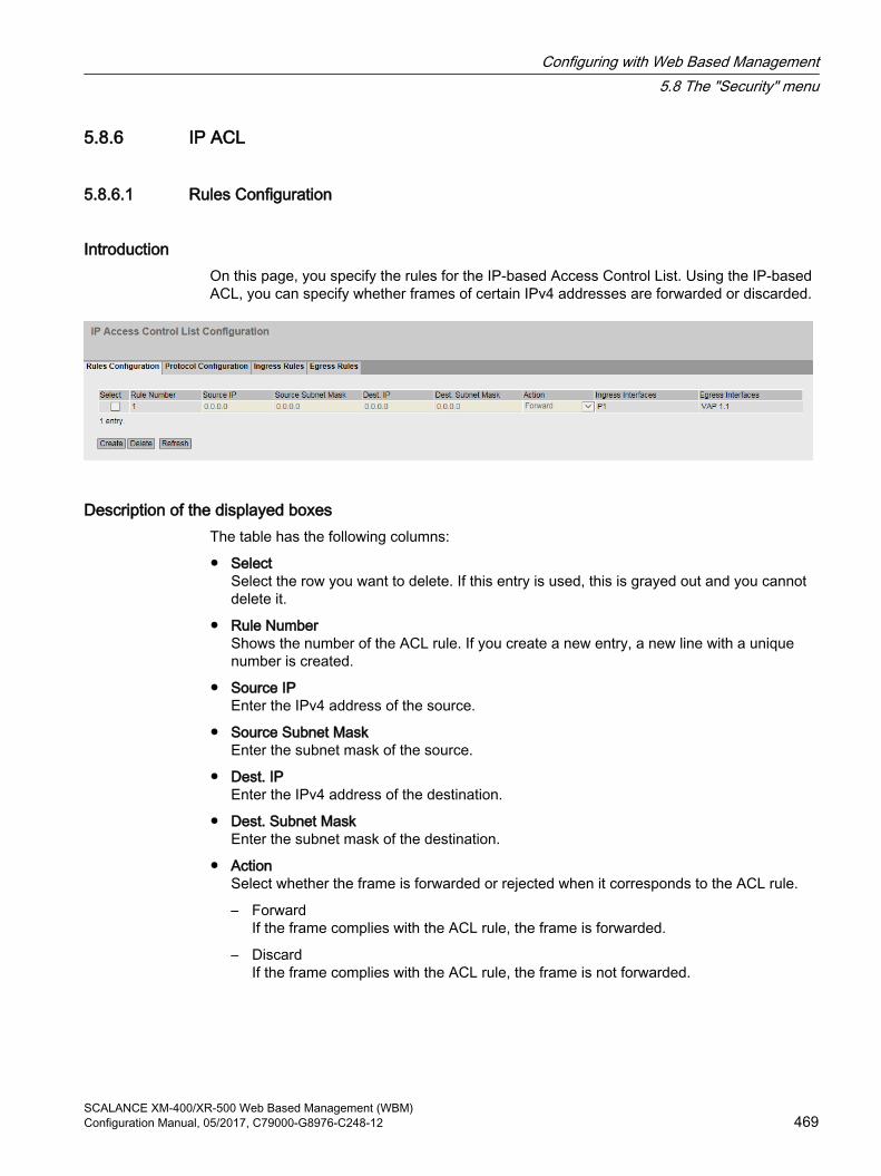
5.8.6 IP ACL
5.8.6.1 Rules Configuration
IntroductionOn this page, you specify the rules for the IP-based Access Control List. Using the IP-based ACL, you can specify whether frames of certain IPv4 addresses are forwarded or discarded.
Description of the displayed boxesThe table has the following columns:
● SelectSelect the row you want to delete. If this entry is used, this is grayed out and you cannot delete it.
● Rule Number Shows the number of the ACL rule. If you create a new entry, a new line with a unique number is created.
● Source IPEnter the IPv4 address of the source.
● Source Subnet MaskEnter the subnet mask of the source.
● Dest. IPEnter the IPv4 address of the destination.
● Dest. Subnet MaskEnter the subnet mask of the destination.
● ActionSelect whether the frame is forwarded or rejected when it corresponds to the ACL rule.
– ForwardIf the frame complies with the ACL rule, the frame is forwarded.
– DiscardIf the frame complies with the ACL rule, the frame is not forwarded.
Configuring with Web Based Management5.8 The "Security" menu
SCALANCE XM-400/XR-500 Web Based Management (WBM)Configuration Manual, 05/2017, C79000-G8976-C248-12 469

● Ingress InterfacesShows a list of all ingress interfaces to which this rule applies.
● Egress InterfacesShows a list of all egress interfaces to which this rule applies.
NoteSubnet mask for individual hosts
If you create the rule for a single system (one IPv4 address), specify the subnet mask "255.255.255.255".
Steps in configuration1. Click the "Create" button. A new row with a unique number (rule number) is created in the
table.
2. Enter the data of the source in "Source IP" and in "Source Subnet Mask".
3. Enter the data of the destination in "Dest. IP" and in "Dest. Subnet Mask".
4. In the "Action" drop-down list select whether the frame is forwarded or rejected when the frame corresponds to the ACL rule.
5. Click the "Set Values" button.
Deleting an entryYou cannot delete active entries.
1. Enable "Select" in the row to be deleted.
2. Click the "Delete" button. The entry is deleted.
5.8.6.2 Protocol ConfigurationOn this page, you specify the rules for protocols.
Settings
Figure 5-24 IP ACL Protocol Configuration
Configuring with Web Based Management5.8 The "Security" menu
SCALANCE XM-400/XR-500 Web Based Management (WBM)470 Configuration Manual, 05/2017, C79000-G8976-C248-12

The table has the following columns:
● Rule NumberShows the number of the protocol rule. When you create a rule, a new row with a unique number is created.
● ProtocolSelect the protocol for which this rule is valid.
● Protocol NumberEnter a protocol number to define further protocols.This box can only be edited if you have set "Other Protocol" for the protocol .
● Source Port Min.Enter the lowest possible port number of the source port.This box can only be edited if you have set "TCP" or "UDP"" for the protocol.
● Source Port Max.Enter the highest possible port number of the source port.This box can only be edited if you have set "TCP" or "UDP" for the protocol.
● Dest. Port Min.Enter the lowest possible port number of the destination port.This box can only be edited if you have set "TCP" or "UDP" for the protocol.
● Dest. Port Max.Enter the highest possible port number of the destination port.This box can only be edited if you have set "TCP" or "UDP" for the protocol.
● Message TypeEnter a message type to decide the format of the message.This box can only be edited if you have set "ICMP" for the protocol.
● Message CodeEnter a message code to specify the function of the message.This box can only be edited if you have set "ICMP" for the protocol.
● DSCPEnter a value for classifying the priority.This box cannot be edited if you have set "ICMP" for the protocol.
Configuring with Web Based Management5.8 The "Security" menu
SCALANCE XM-400/XR-500 Web Based Management (WBM)Configuration Manual, 05/2017, C79000-G8976-C248-12 471

5.8.6.3 Ingress Rules
IntroductionOn this page, you specify the ACL rules according to which incoming frames are handled by interfaces. You specify the ACL rules in the "Rules Configuration" tab.
Description of the displayed boxesThe page contains the following boxes:
● Interface Select the required interface from the drop-down list. The available interfaces depend on your device. To select a VLAN interface, an IP interface must be configured.
Note
If you use a VLAN interface, the ACL rule applies to all ports that belong to the VLAN.
● Add RuleIn the drop-down list select the ACL rule to be assigned to the interface.
Configuring with Web Based Management5.8 The "Security" menu
SCALANCE XM-400/XR-500 Web Based Management (WBM)472 Configuration Manual, 05/2017, C79000-G8976-C248-12

● AddTo permanently assign the ACL rule to the interface, click the "Add" button. The configuration is shown in the table.
● Remove RuleFrom the "Remove rule" drop-down list, select the ACL rule to be deleted.
● RemoveTo remove the ACL rule from the interface, click the "Remove" button.
The table has the following columns:
● Rule OrderShows the order of the ACL rules.
● Rule Number Shows the number of the ACL rule.
● ProtocolShows the protocol for which this rule is valid.
● Protocol NumberShows the protocol number.
● Source IPShows the IPv4 address of the source.
● Source Subnet MaskShows the subnet mask of the source.
● Dest IPShows the IP address of the destination.
● Dest. Subnet MaskShows the subnet mask of the destination.
● ActionSelect whether the frame is forwarded or rejected when it corresponds to the ACL rule.
– ForwardIf the frame complies with the ACL rule, the frame is forwarded.
– DiscardIf the frame complies with the ACL rule, the frame is not forwarded.
● Source Port Min.Shows the lowest possible port number of the source port.
● Source Port Max.Shows the highest possible port number of the source port.
● Dest. Port Min.Shows the lowest possible port number of the destination port.
● Dest. Port Max.Shows the highest possible port number of the destination port.
● Message TypeShows a message type to decide the format of the message.
Configuring with Web Based Management5.8 The "Security" menu
SCALANCE XM-400/XR-500 Web Based Management (WBM)Configuration Manual, 05/2017, C79000-G8976-C248-12 473

● Message CodeShows a message code to specify the function of the message.
● DSCPShows a value for classifying the priority.
Steps in configurationFollow the steps below to assign an ACL rule to an interface:
1. Select the interface from the "Interface" drop-down list.
2. Select the ACL rule in the "Add Rule" drop-down list.
3. Click the "Add" button. A new entry is generated in the table.
Follow the steps below to assign an ACL rule to an interface:
Noteactive rules
You cannot delete active rules.
1. Select the interface from the "Interface" drop-down list.
2. Select the ACL rule in the "Remove Rule" drop-down list.
3. Click the "Remove" button. The corresponding entry is deleted.
Configuring with Web Based Management5.8 The "Security" menu
SCALANCE XM-400/XR-500 Web Based Management (WBM)474 Configuration Manual, 05/2017, C79000-G8976-C248-12

5.8.6.4 Egress Rules
IntroductionOn this page, you specify the ACL rules according to which outgoing frames are handled by interfaces. You specify the ACL rules in the "Rules Configuration" tab.
Configuring with Web Based Management5.8 The "Security" menu
SCALANCE XM-400/XR-500 Web Based Management (WBM)Configuration Manual, 05/2017, C79000-G8976-C248-12 475

Description of the displayed boxesThe page contains the following boxes:
● Interface Select the required interface from the drop-down list. The available interfaces depend on the device.To select a VLAN interface, an IP interface must be configured.
Note
If you use a VLAN interface, the ACL rule applies to all ports that belong to the VLAN.
● Add RuleIn the drop-down list select the ACL rule to be assigned to the interface.
● AddTo assign the ACL rule to the interface, click the "Add" button. The configuration is shown in the table.
● Remove RuleFrom the "Remove rule" drop-down list, select the ACL rule to be deleted.
● RemoveTo remove the ACL rule from the interface, click the "Remove" button.
The table has the following columns:
● Rule OrderShows the order of the ACL rules.
● Rule Number Shows the number of the ACL rule.
● ProtocolShows the protocol for which this rule is valid.
● Protocol NumberShows the protocol number.
● Source IPShows the IPv4 address of the source.
● Source Subnet MaskShows the subnet mask of the source.
● Dest IPShows the IP address of the destination.
● Dest. Subnet MaskShows the subnet mask of the destination.
● ActionSelect whether the frame is forwarded or rejected when it corresponds to the ACL rule.
– ForwardIf the frame complies with the ACL rule, the frame is forwarded.
– DiscardIf the frame complies with the ACL rule, the frame is not forwarded.
Configuring with Web Based Management5.8 The "Security" menu
SCALANCE XM-400/XR-500 Web Based Management (WBM)476 Configuration Manual, 05/2017, C79000-G8976-C248-12

● Source Port Min.Shows the lowest possible port number of the source port.
● Source Port Max.Shows the highest possible port number of the source port.
● Dest. Port Min.Shows the lowest possible port number of the destination port.
● Dest. Port Max.Shows the highest possible port number of the destination port.
● Message TypeShows a message type to decide the format of the message.
● Message CodeShows a message code to specify the function of the message.
● DSCPShows a value for classifying the priority.
Steps in configurationFollow the steps below to assign an ACL rule to an interface:
1. Select the interface from the "Interface" drop-down list.
2. Select the ACL rule in the "Add Rule" drop-down list.
3. Click the "Add" button. A new entry is generated in the table.
Follow the steps below to remove an ACL rule from an interface:
Noteactive rules
You cannot delete active rules.
1. Select the interface from the "Interface" drop-down list.
2. Select the ACL rule in the "Remove Rule" drop-down list.
3. Click the "Remove" button. The corresponding entry is removed in the table.
5.8.7 Management ACL
Description of configurationOn this page, you can increase the security of your device. To specify which station with which IP address is allowed to access your device, configure the IP address or an entire address range.
You can select the protocols and the ports of the station with which it is allowed to access the device. You define the VLAN in which the station may be located. This ensures that only certain stations within a VLAN have access to the device.
Configuring with Web Based Management5.8 The "Security" menu
SCALANCE XM-400/XR-500 Web Based Management (WBM)Configuration Manual, 05/2017, C79000-G8976-C248-12 477

Description of the displayed boxes
NoteIf you enable this function, note the following
A bad configuration on the "Management Access Control List" page can result in you being unable to access the device. You should therefore configure an access rule that allows access to the management before you enable the function.
The page contains the following boxes:
● Management ACLEnable or disable access control to the management of the IE switch.As default, the function is disabled.
Note
If the function is disabled, there is unrestricted access to the management of the IE switch. The configured access rules are only taken into account when the function is enabled.
● IP AddressEnter the IP address or the network address to which the rule will apply.If you use the IPv4 address 0.0.0.0, the settings apply to all IPv4 addresses.If you use the IPv6 address :: the settings apply to all IPv6 addresses.
● Subnet Mask / Prefix LengthEnter the subnet mask or the prefix length.The subnet mask 255.255.255.255 is for a specific IPv4 address. If you want to allow a subnet, for example a C subnet, enter 255.255.255.0. The subnet mask 0.0.0.0 applies to all subnets.
The table has the following columns:
● SelectSelect the row you want to delete.
● Rule OrderShows the order of the ACL rules.
● IP Address Shows the IP address.
Configuring with Web Based Management5.8 The "Security" menu
SCALANCE XM-400/XR-500 Web Based Management (WBM)478 Configuration Manual, 05/2017, C79000-G8976-C248-12

● Subnet Mask / Prefix LengthShows the subnet mask or the prefix length.
● VLANs AllowedEnter the number of the VLAN in which the device is located. The station can only access the device if it is located in this configured VLAN. If this input box remains empty, there is no restriction relating to the VLANs.
● Out-BandSpecify whether or not the IPv4 address can access the switch via the out-band port.
● SNMPSpecify whether the station (or the IP address) can access the device using the SNMP protocol.
● TELNETSpecify whether the station (or the IP address) can access the device using the TELNET protocol.
● HTTPSpecify whether the station (or the IP address) can access the device using the HTTP protocol.
● HTTPSSpecify whether the station (or the IP address) can access the switch using the HTTPS protocol.
● SSHSpecify whether the station (or the IP address) can access the switch using the SSH protocol.
● List of portsSpecify whether the station (or the IP address) can access this device via this port (Slot.Port).
Steps in configurationChanging the entry
1. Configure the data of the entry you want to modify.
2. Click the "Set Values" button to transfer the changes to the device.
Creating a new entry
Note
Note that a bad configuration may mean that you can no longer access the device.
You can then only remedy this via the serial interface or by resetting the device to the factory defaults and then reconfiguring.
1. In the "IP Address" input box, enter the IP address of the device and in the "Subnet Mask / Prefix Length" input box the corresponding subnet mask or prefix length.
2. Click the "Create" button to create a new row in the table.
Configuring with Web Based Management5.8 The "Security" menu
SCALANCE XM-400/XR-500 Web Based Management (WBM)Configuration Manual, 05/2017, C79000-G8976-C248-12 479

3. Configure the entries of the new row.
4. Click the "Set Values" button to transfer the new entry to the device.
Deleting entries
1. Select the check box in the row to be deleted.
2. Repeat this procedure for every entry you want to delete.
3. Click the "Remove" button. The entries are deleted and the page is updated.
Configuring with Web Based Management5.8 The "Security" menu
SCALANCE XM-400/XR-500 Web Based Management (WBM)480 Configuration Manual, 05/2017, C79000-G8976-C248-12

Troubleshooting/FAQ 66.1 Firmware update - via WBM
Requirement● The device has an IP address.
● The user is logged in with administrator rights.
Firmware update via HTTP1. Click "System > Load&Save" in the navigation area. Click the "HTTP" tab.
2. Click the "Load" button in the "Firmware" table row.
3. Go to the storage location of the firmware file.
4. Click the "Open" button in the dialog. The file is uploaded.
Firmware update - via TFTP1. Click "System > Load&Save" in the navigation area. Click the "TFTP" tab.
2. Enter the IP address of the TFTP server in the "TFTP Server Address" input box.
3. Enter the port of the TFTP server in the "TFTP Server Port" input box.
4. Click the "Load file" button in the "Firmware" table row.
5. Go to the storage location of the firmware file.
6. Click the "Open" button in the dialog. The file is uploaded.
ResultThe firmware is has been transferred completely to the device.
On the "Information > Versions" there are the entries "Firmware" and "Firmware Running". Firmware Runningshows the version of the current firmware. "Firmware" shows the firmware version stored after loading the firmware. To activate this firmware, restart the device with "System > Restart".
6.2 Firmware update via WBM or CLI not possible
CauseIf there is a power failure during the firmware update, it is possible that the IE switch is no longer accessible using Web Based Management or the Command Line Interface.
SCALANCE XM-400/XR-500 Web Based Management (WBM)Configuration Manual, 05/2017, C79000-G8976-C248-12 481

SolutionIf the IE switch cannot be reached using WBM or CLI, you can download the firmware to your IE switch using TFTP.
Follow the steps below to load new firmware using TFTP:
1. Turn off the power to the IE switch.
2. Press the Reset button and reconnect the power to the IE switch while holding down the button.
3. Hold down the button until the red fault LED (F) starts to flash after approximately 30 seconds.
4. Release the button.The bootloader waits in this state for a new firmware file that you can download by TFTP.
5. Connect a PC via the Ethernet interface with the out-band interface of the IE switch.
6. Assign an IP address to the IE switch with the Primary Setup Tool.
7. In the command prompt, change to the directory where the file with the new firmware is located and then execute the command "tftp -i <ip address> PUT <firmware>". As an alternative, you can use a different TFTP client.
ResultThe firmware is transferred to the IE switch.
Note
Please note that the transfer of the firmware can take several minutes. During the transmission, the red error LED (F) flashes.
Once the firmware has been transferred completely to the IE switch, the IE switch is restarted automatically.
6.3 Message: SINEMA configuration not yet acceptedWhen the following message is displayed in the display area an error has occurred transferring the configuration from STEP 7 Basic / Professional as of V13 to the device:
"SINEMA Configuration not accepted yet. With restart of device, all configuration changes will be lost."
One possible cause is, for example, that during transfer the device was not reachable.
If you now change a parameter directly on the device (WBM/CLI/SNMP) these changes are lost when the device restarts.
Solution1. Open the relevant STEP 7 project in STEP 7 Basic / Professional
2. Open the project view.
Troubleshooting/FAQ6.3 Message: SINEMA configuration not yet accepted
SCALANCE XM-400/XR-500 Web Based Management (WBM)482 Configuration Manual, 05/2017, C79000-G8976-C248-12

3. Select the device in the project tree.
4. Select the "Go to network view" command in the shortcut menu.
5. Select the device in the network view.
6. In the shortcut menu of the selected device select the command "SCALANCE configuration > Save as start configuration".
ResultThe configuration is saved on the device. The message is no longer visible in the display area. A configuration change directly on the device is no longer lost due to a restart of the device.
Troubleshooting/FAQ6.3 Message: SINEMA configuration not yet accepted
SCALANCE XM-400/XR-500 Web Based Management (WBM)Configuration Manual, 05/2017, C79000-G8976-C248-12 483

Troubleshooting/FAQ6.3 Message: SINEMA configuration not yet accepted
SCALANCE XM-400/XR-500 Web Based Management (WBM)484 Configuration Manual, 05/2017, C79000-G8976-C248-12
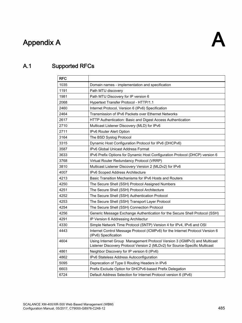
Appendix A AA.1 Supported RFCs
RFC 1035 Domain names - implementation and specification1191 Path MTU discovery1981 Path MTU Discovery for IP version 62068 Hypertext Transfer Protocol - HTTP/1.12460 Internet Protocol, Version 6 (IPv6) Specification2464 Transmission of IPv6 Packets over Ethernet Networks2617 HTTP Authentication: Basic and Digest Access Authentication2710 Multicast Listener Discovery (MLD) for IPv62711 IPv6 Router Alert Option3164 The BSD Syslog Protocol3315 Dynamic Host Configuration Protocol for IPv6 (DHCPv6)3587 IPv6 Global Unicast Address Format3633 IPv6 Prefix Options for Dynamic Host Configuration Protocol (DHCP) version 63768 Virtual Router Redundancy Protocol (VRRP)3810 Multicast Listener Discovery Version 2 (MLDv2) for IPv64007 IPv6 Scoped Address Architecture4213 Basic Transition Mechanisms for IPv6 Hosts and Routers4250 The Secure Shell (SSH) Protocol Assigned Numbers4251 The Secure Shell (SSH) Protocol Architecture4252 The Secure Shell (SSH) Authentication Protocol4253 The Secure Shell (SSH) Transport Layer Protocol4254 The Secure Shell (SSH) Connection Protocol4256 Generic Message Exchange Authentication for the Secure Shell Protocol (SSH)4291 IP Version 6 Addressing Architectur4330 Simple Network Time Protocol (SNTP) Version 4 for IPv4, IPv6 and OSI4443 Internet Control Message Protocol (ICMPv6) for the Internet Protocol Version 6
(IPv6) Specification4604 Using Internet Group Management Protocol Version 3 (IGMPv3) and Multicast
Listener Discovery Protocol Version 2 (MLDv2) for Source-Specific Multicast4861 Neighbor Discovery for IP version 6 (IPv6)4862 IPv6 Stateless Address Autoconfiguration5095 Deprecation of Type 0 Routing Headers in IPv66603 Prefix Exclude Option for DHCPv6-based Prefix Delegation6724 Default Address Selection for Internet Protocol version 6 (IPv6)
SCALANCE XM-400/XR-500 Web Based Management (WBM)Configuration Manual, 05/2017, C79000-G8976-C248-12 485

Appendix AA.1 Supported RFCs
SCALANCE XM-400/XR-500 Web Based Management (WBM)486 Configuration Manual, 05/2017, C79000-G8976-C248-12
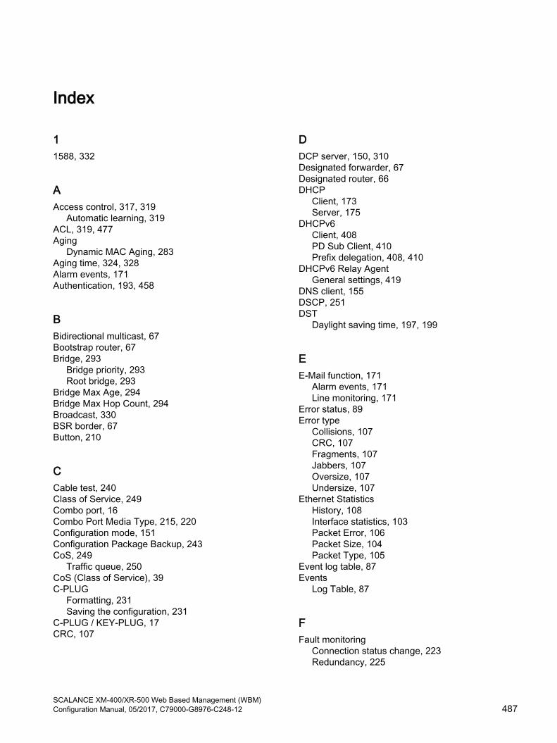
Index
11588, 332
AAccess control, 317, 319
Automatic learning, 319ACL, 319, 477Aging
Dynamic MAC Aging, 283Aging time, 324, 328Alarm events, 171Authentication, 193, 458
BBidirectional multicast, 67Bootstrap router, 67Bridge, 293
Bridge priority, 293Root bridge, 293
Bridge Max Age, 294Bridge Max Hop Count, 294Broadcast, 330BSR border, 67Button, 210
CCable test, 240Class of Service, 249Combo port, 16Combo Port Media Type, 215, 220Configuration mode, 151Configuration Package Backup, 243CoS, 249
Traffic queue, 250CoS (Class of Service), 39C-PLUG
Formatting, 231Saving the configuration, 231
C-PLUG / KEY-PLUG, 17CRC, 107
DDCP server, 150, 310Designated forwarder, 67Designated router, 66DHCP
Client, 173Server, 175
DHCPv6Client, 408PD Sub Client, 410Prefix delegation, 408, 410
DHCPv6 Relay AgentGeneral settings, 419
DNS client, 155DSCP, 251DST
Daylight saving time, 197, 199
EE-Mail function, 171
Alarm events, 171Line monitoring, 171
Error status, 89Error type
Collisions, 107CRC, 107Fragments, 107Jabbers, 107Oversize, 107Undersize, 107
Ethernet StatisticsHistory, 108Interface statistics, 103Packet Error, 106Packet Size, 104Packet Type, 105
Event log table, 87Events
Log Table, 87
FFault monitoring
Connection status change, 223Redundancy, 225
SCALANCE XM-400/XR-500 Web Based Management (WBM)Configuration Manual, 05/2017, C79000-G8976-C248-12 487

FilterFilter configuration, 317
Forward Delay, 294
GGeographic coordinates, 153Glossary, 13GMRP, 325Groups, 449GVRP, 259
HHardware Revision, 85Hello time, 294HRP, 287HTTP
Load/save, 159HTTPS
Server, 149
IIEEE 1588, 332IGMP, 324IGMP Join, 67Information
ARP table, 86Groups, 148IPv6 Neighbor Table, 87LLDP, 113Log Table, 87Ring redundancy, 98, 100Role, 147Security, 144, 147SNMP, 143Spanning Tree, 91Start page, 78Versions, 83
IPv4OSPF, 60VRRP, 59VRRPv3, 59
IPv4 address, 154IPv4 routing
MSDP Cache, 130NAT Translations, 124OSPFv2 interfaces, 117OSPFv2 LSDB (information), 122OSPFv2 neighbors, 118
OSPFv2 Virtual Neighbors, 120PIM BSRs, 129PIM interfaces, 125PIM Neighbors, 126PIM Routes, 127PIM RPs, 128RIPv2 Statistics, 123Routing table, 116
IPv6Notation, 28OSPFv3, 64VRRPv3, 59
IPv6 routingOSPFv3 AS-Scope LSDB, 136, 137OSPFv3 Interfaces, 132OSPFv3 Link-Scope LSDB, 139OSPFv3 Neighbors, 133OSPFv3 virtual neighbors, 135Routing table, 131, 140Static routes, 411
KKEY-PLUG, 229, 232
Formatting, 231
LLACP, 307Layer 2, 245
MLD (IPv6), 329Layer 3, 232Layer 3 (IPv4), 339
Configuration, 339Layer 3 (IPv6), 404
Configuration, 404Line monitoring, 171Link Check, 101Link Check Status, 101LLDP, 113, 312Local users, 444Location, 153Logging on
via HTTP, 75via HTTPS, 75
LogoutAutomatic, 210
Loop, 304Loop detection, 304
Index
SCALANCE XM-400/XR-500 Web Based Management (WBM)488 Configuration Manual, 05/2017, C79000-G8976-C248-12

MMAC ACL, 463, 465
Configuration, 465, 467Maintenance data, 84Management ACL, 477Manufacturer, 84Manufacturer ID, 85Mirroring, 43
General, 274IP Flow, 282MAC Flow, 281Port, 279VLAN, 280
MLD, 328MSDP, 67, 401
Peer, 403MSDP Cache, 130MSTP, 292, 300
Port, 295Port parameters, 301
MSTP instance, 301, 302Multicast, 321Multiple Spanning Tree, 295, 300
NNAPT
Configuring, 350NAT
Configuring, 345, 347, 348NAT Translations, 124Near Field Communication, 151Negotiation, 215NFC, 151NTP, 321
Client, 205
OOrder ID, 85OSPF
Areas, 60Link State Advertisement, 60Router, 60Router status, 60
OSPF (IPv4)Area range, 383Areas, 382Configuration, 380
Interface authentication, 387OSPFv2 Interfaces, 385OSPFv2 LSDB (information), 122OSPFv2 neighbors, 118OSPFv2 Virtual Neighbors, 120Virtual link authentication, 391Virtual Links, 388
OSPF (IPv6)Area Range, 434Areas, 432OSPFv3 AS-Scope LSDB, 136, 137OSPFv3 interfaces, 435OSPFv3 Link-Scope LSDB, 139OSPFv3 Neighbors, 133OSPFv3 virtual neighbors, 135Virtual Links, 437
OSPFv3Configuration, 430
PPacket Error
Collisions, 107CRC, 107Fragments, 107Jabbers, 107Oversize, 107Undersize, 107
Packet error statistics, 106Password, 451
Options, 453PIM
Interfaces, 397Protocol, 397RP Candidate, 400RP Static, 399
PIM BSRs, 129PIM interfaces, 125PIM Neighbors, 126Ping, 234PLUG, 232
C-PLUG, (C-PLUG)KEY-PLUG, (KEY-PLUG)
PoE, 235, 238Port, 238
point-to-point, 45Port, 217
Link Check, 101Port configuration, 214, 222
Port configuration, 217, 222
Index
SCALANCE XM-400/XR-500 Web Based Management (WBM)Configuration Manual, 05/2017, C79000-G8976-C248-12 489

Port diagnosticsCable test, 240SFP diagnostics, 242
Power over Ethernet, 18, 235Port, 238
Power supplyMonitoring, 222
Prioritization, 252Priority, 252, 294PROFINET, 225PST tool, 310PTP, 332, 333, 334
General, 333Port, 334Transparent clock, 333
QQoS, 252QoS Trust, 39
RRADIUS, 454Rate control, 254RCDP Server, 150Reboot, 156Redundancy, 285, 287Redundancy procedure
HRP, 46Redundant networks, 293Rendezvous point, 66Reset, 156Ring redundancy, 285
HRP, 247, 285MRP, 247, 285Ring ports, 285Standby, 287
RIP (IPv4)RIPv2 Statistics, 123
RIPngConfiguration, 440Interfaces, 440RIPng Statistics, 140
RIPv2Configuration, 393Interfaces, 393
RMONHistory, 337Statistics, 335
Roles, 447
Root Max Age, 294Route Map, 353, 412Route maps, 353, 412Routing, 58, 351
IPv4 routing table, 116IPv6 routing table, 131Static IPv4 routes, 351Static routes, 58VRRP, 58
RSTP, 292Rule, 463, 465, 469
Configuration, 469Egress, 467, 469Ingress, 465, 469IP ACL, 469
SScope of the manual, 11Security settings, 190Select/Set button, 210Serial number, 85SFP diagnostics, 242SHA algorithm, 190SIMATIC NET glossary, 13SMTP
Client, 149SNMP, 35, 151, 186, 190
Groups, 190Overview, 143SNMPv1, 35SNMPv2c, 35SNMPv3, 35Trap, 189Users, 192
Software version, 85Source specific multicast, 67Spanning Tree,
Information, 91MSTP, Passive listening, Rapid Spanning Tree, 45RSTP,
Sparse mode, 66SSH
Server, 149Standby, 287Standby redundancy, 55Start page, 78Static routes
IPv6 routes, 411STEP 7, 310
Index
SCALANCE XM-400/XR-500 Web Based Management (WBM)490 Configuration Manual, 05/2017, C79000-G8976-C248-12

STP, 292Subnet mask, 23Subnets
Configuration (IPv4), 343Configuration (IPv6), 406Connected Subnets (IPv6), 406Overview (IPv4), 340
Syslog, 212Client, 149
SystemConfiguration, 148General information, 152
System event logAgent, 212
System eventsConfiguration, 167Severity filter, 170
TTelnet
Server, 149TFTP
Load/save, 162Time, 150Time of day
Manual setting, 195Precision Time Protocol, 208PTP Client, 208SIMATIC Time Client, 207SNTP (Simple Network Time Protocol), 202System time, 195Time zone, 204, 207Time-of-day synchronization, 202UTC time, 204, 207
Time setting, 150Trust Mode, 252
UUser Groups, 449
VVLAN, 37, 263
Group, 263Port VID, 262Priority, 262Tag, 262VLAN ID, 40VLAN tag, 38
VRRPBackup router, 59Interface Tracking, 370Master router, 59Virtual router, 59VRRP address configuration (IPv4), 369VRRP address overview (IPv4), 369VRRP addresses overview (IPv4), 377VRRP configuration (IPv4), 367VRRP router, 59VRRP routers (IPv4), 364, 422VRRP statistics, 94VRRPv3 address configuration (IPv6), 428VRRPv3 Addresses Configuration (IPv4), 377VRRPv3 addresses overview (IPv6), 427VRRPv3 Configuration (IPv4), 375VRRPv3 Configuration (IPv6), 425VRRPv3 routers (IPv4), 372
VRRPv3Interface Tracking, 378, 429VRRPv3 Statistics, 96
WWeb Based Management, 73
Requirement, 73
Index
SCALANCE XM-400/XR-500 Web Based Management (WBM)Configuration Manual, 05/2017, C79000-G8976-C248-12 491

Index
SCALANCE XM-400/XR-500 Web Based Management (WBM)492 Configuration Manual, 05/2017, C79000-G8976-C248-12