Embed Size (px)
Citation preview

Scalable nanostructured membranes forsolid-oxide fuel cellsMasaru Tsuchiya1,2*, Bo-Kuai Lai2 and Shriram Ramanathan2
The use of oxide fuel cells and other solid-state ionic devices inenergy applications is limited by their requirement for elevatedoperating temperatures, typically above 800 88888C (ref. 1). Thin-film membranes allow low-temperature operation by reducingthe ohmic resistance of the electrolytes2. However, althoughproof-of-concept thin-film devices have been demonstrated3,scaling up remains a significant challenge because large-areamembranes less than ∼100 nm thick are susceptible to mech-anical failure. Here, we report that nanoscale yttria-stabilizedzirconia membranes with lateral dimensions on the scale ofmillimetres or centimetres can be made thermomechanicallystable by depositing metallic grids on them to function asmechanical supports. We combine such a membrane with ananostructured dense oxide cathode to make a thin-film solid-oxide fuel cell that can achieve a power density of155 mW cm–2 at 510 88888C. We also report a total power outputof more than 20 mW from a single fuel-cell chip. Our large-area membranes could also be relevant to electrochemicalenergy applications such as gas separation, hydrogen pro-duction and permeation membranes.
Electrochemical active membranes with oxygen-ion conductorsare crucial components in various devices used in environmentaland energy technologies, including solid-oxide fuel cells1, electrolyticdevices for NOx reduction4, oxygen-separation membranes5 andexhaust gas sensors6. For all such applications, the operating tempera-ture is typically �700 8C or above, placing severe restrictions on thescope of applications, requiring bulky thermal shielding and resultingin slow start-up. A lower operating temperature would allow a greaterflexibility in the choice of materials, compact stack design and superiorstart–stop capabilities. The use of a nanoscale electrolyte allows theoperating temperature of these devices to be lowered to 500 8C orbelow2. Of the various solid-state ionic devices listed above, solid-oxide fuel cells (SOFCs) are of particular interest. They have numerousadvantages, including a higher energy-conversion efficiency than con-ventional electric power generation systems, high volumetric energydensity and high specific power. Because the performance of aSOFC is sensitive to electrolyte thickness, the use of micrometre-scale thick-film technology to reduce the operating temperature ofSOFCs has been proposed7–11, and further downscaling to nano-metre-scale membranes is considered to be a promising path for dra-matically improving the performance of SOFCs in the 300–500 8Crange3,12–25. Because of the need for ultrathin (�100 nm or less)films in these devices, microfabrication methods are typically usedto create free-standing membranes on silicon using chemicaletching. Although several substrates have been proposed, includingnickel foil9, porous nickel cermet8 or glass19, the silicon platform hasinherent advantages, including the possibility of integrated on-chippower devices using three-dimensional integration.
Proof-of-concept micro-SOFCs (mSOFCs) have been demon-strated, but a rather challenging aspect has been the scaling of the
electrochemical active area. In solid-state ionic devices, large-areathin membranes are desirable for enhancement of performance,because the membranes have a smaller resistance to the large fluxof ions. However, this is mechanically challenging, because criticalstress to failure increases in proportion to (h/r)2
, where h is thethickness of the membrane and r is the radius of the active mem-brane area26. As a result of this parabolic dependence, the fabrica-tion and testing of mSOFCs, including a nanometre-scale thin-film electrolyte, faces significantly different challenges from thoseof micrometre-scale SOFCs. For example, in the sub-100-nmyttria-stabilized zirconia (YSZ) thin films grown on silicon used inthis study, critical stress towards buckling failure was reached atroom temperature, even in the micrometre-scale in-plane dimen-sion18,27,28. Mechanical stability in the post-buckling regime is extre-mely sensitive to a number of parameters, including film thickness,density and process conditions. Junction sizes in previous studieson mSOFCs with nanometre-scale electrolytes have typically beenlimited to a few hundred micrometres (total area, ,0.1 mm2) orless. It has been reported that free-standing fuel-cell membranesfail catastrophically if the active area is increased in its lateral dimen-sions above several hundred micrometres17. As well as yield losses,this leads to the safety issue of mixing fuels and oxygen (air).Furthermore, area utilization in previous studies on silicon-basedmSOFCs has been on the order of a few percent, despite the potentialpromise of substantially increasing volumetric and gravimetricpower density over that for other fuel-cell types and batteries. Theactive area cannot be increased by simply interconnecting severalsmall microscale junctions because of the extremely poor area util-ization resulting from the KOH anisotropic etch process. Forexample, a square active area with edges of 100 mm, fabricatedon a 525-mm-thick silicon wafer, requires a square etch holewith edges of 843 mm, which is equivalent to only 1.4% areautilization (Fig. 1a).
To make thin-film free-standing membrane technology practi-cally relevant, it is crucial to develop new methods to scale up theelectrochemical active area. For mSOFC, in particular, it is impor-tant to scale the active area while keeping the power density high.This challenge has severely limited the technology, despite over adecade of research into thin-film SOFCs. Scaling of the active areain the range of mm2 with a power density of the order of100 mW cm22 at �500 8C is a key milestone in bringing mSOFCtechnology closer to practical applications. For example, chip-scalemicro-electro-mechanical systems (MEMS) devices have the poten-tial to be powered by fuel cells with active areas of several mm2 andpower densities of 100 mW cm22, because their typical powerrequirement is of the order of several milliwatts29.
Here, we demonstrate the use of microfabricated metallic gridstructures located directly on nanostructured free-standing fuel-cell membranes to increase the electrochemical active area to over10 mm2, while retaining high power densities. This represents an
1SiEnergy Systems LLC, Boston, Massachusetts, 02110, USA, 2Harvard School of Engineering and Applied Sciences, Harvard University, Cambridge,Massachusetts, 02138, USA. *e-mail: [email protected]
LETTERSPUBLISHED ONLINE: 3 APRIL 2011 | DOI: 10.1038/NNANO.2011.43
NATURE NANOTECHNOLOGY | VOL 6 | MAY 2011 | www.nature.com/naturenanotechnology282
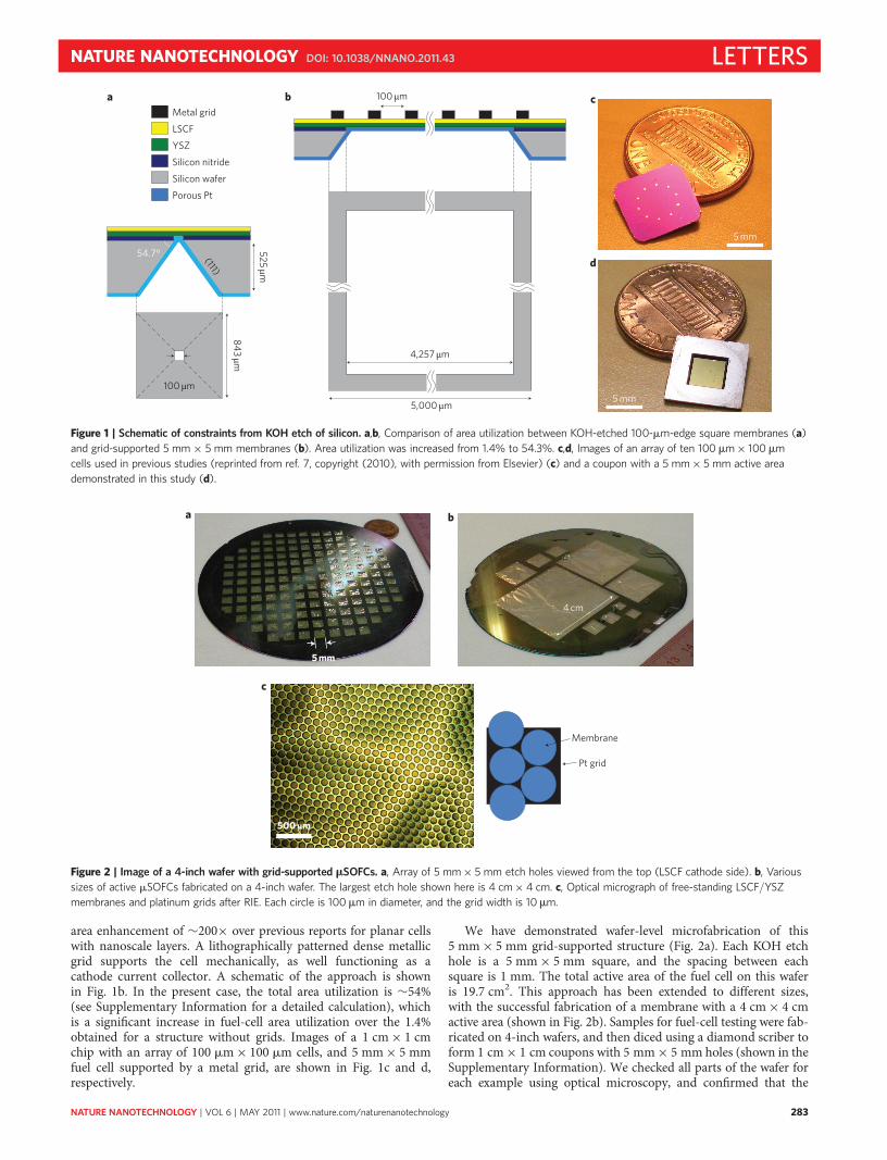
area enhancement of �200× over previous reports for planar cellswith nanoscale layers. A lithographically patterned dense metallicgrid supports the cell mechanically, as well functioning as acathode current collector. A schematic of the approach is shownin Fig. 1b. In the present case, the total area utilization is �54%(see Supplementary Information for a detailed calculation), whichis a significant increase in fuel-cell area utilization over the 1.4%obtained for a structure without grids. Images of a 1 cm × 1 cmchip with an array of 100 mm × 100 mm cells, and 5 mm × 5 mmfuel cell supported by a metal grid, are shown in Fig. 1c and d,respectively.
We have demonstrated wafer-level microfabrication of this5 mm × 5 mm grid-supported structure (Fig. 2a). Each KOH etchhole is a 5 mm × 5 mm square, and the spacing between eachsquare is 1 mm. The total active area of the fuel cell on this waferis 19.7 cm2. This approach has been extended to different sizes,with the successful fabrication of a membrane with a 4 cm × 4 cmactive area (shown in Fig. 2b). Samples for fuel-cell testing were fab-ricated on 4-inch wafers, and then diced using a diamond scriber toform 1 cm × 1 cm coupons with 5 mm × 5 mm holes (shown in theSupplementary Information). We checked all parts of the wafer foreach example using optical microscopy, and confirmed that the
a b
d
5 mm
c
5 mm
54.7° (111)
525 µm
843 µm
100 µm
LSCF
YSZ
Silicon nitride
Silicon wafer
Porous Pt
Metal grid100 µm
5,000 µm
4,257 µm
Figure 1 | Schematic of constraints from KOH etch of silicon. a,b, Comparison of area utilization between KOH-etched 100-mm-edge square membranes (a)
and grid-supported 5 mm × 5 mm membranes (b). Area utilization was increased from 1.4% to 54.3%. c,d, Images of an array of ten 100 mm × 100 mm
cells used in previous studies (reprinted from ref. 7, copyright (2010), with permission from Elsevier) (c) and a coupon with a 5 mm × 5 mm active area
demonstrated in this study (d).
c
500 µm
Pt grid
Membrane
b
4 cm
a
5 mm
Figure 2 | Image of a 4-inch wafer with grid-supported mSOFCs. a, Array of 5 mm × 5 mm etch holes viewed from the top (LSCF cathode side). b, Various
sizes of active mSOFCs fabricated on a 4-inch wafer. The largest etch hole shown here is 4 cm × 4 cm. c, Optical micrograph of free-standing LSCF/YSZ
membranes and platinum grids after RIE. Each circle is 100mm in diameter, and the grid width is 10mm.
NATURE NANOTECHNOLOGY DOI: 10.1038/NNANO.2011.43 LETTERS
NATURE NANOTECHNOLOGY | VOL 6 | MAY 2011 | www.nature.com/naturenanotechnology 283

cells, composed of sub-100-nm stacks, were successfully fabricatedwithout defects. A representative optical micrograph is shown inFig. 2c. We have demonstrated the successful fabrication of a chal-lenging design of cell, with the scale of the cell area (centimetres)being nearly 100,000 times larger than the cell thickness (100 nmscale), far beyond the buckling failure limit of free-standing YSZmembranes on silicon of comparable thickness28.
A scanning electron microscopy (SEM) image of a grid-sup-ported SOFC before fuel-cell testing (no annealing) is shown inFig. 3a. Various shapes and sizes of grid were tested and evaluated,including squares and triangles. Circular and hexagonal shapes werefound to be the most stable. This is expected, because there is a largeanisotropy in the mechanical properties of square-shaped cellularsolids, and triangular corners increase susceptibility to failure30.The circular membranes were slightly buckled, in agreement witha previous report on slight compressive stress (–40 MPa) at roomtemperature15. The bulged dome was flattened on annealing(shown in Fig. 3b). Membrane flattening following fuel-cell testingsuggests that compressive stress is relieved and changes to tensilestress on annealing. This relaxation of the compressive stress has
been reported in previous studies on La0.6Sr0.4Co0.8Fe0.2O3 (LSCF)and YSZ films as a result of the incorporation of oxygen duringannealing15 or diffusion of interstitial atoms24. The grid was�1.5 mm thick, with sharp edges, as shown in Fig. 3c. A representa-tive cross-sectional micrograph showing an LSCF cathode (47 nm),a YSZ electrolyte (54 nm) and platinum porous anode is shown inFig. 3d. From a series of cross-sectional and plan-view electronmicrographs of fuel cells, we confirmed that the thin YSZ electrolytewas dense and crack-free over a large area. Plan-view morphology ofthe platinum anode before and after fuel-cell testing can be found inthe Supplementary Information.
Interestingly, the grids were also buckled. The grid bucklinginitially had fourfold rotational symmetry, similar to the obser-vations of Ziebart et al. on compressively pre-stressed membranes31;this fourfold rotational symmetry of the membranes then changedslightly (owing to gas pressure), resulting in the shape shown inFig. 4a. The buckling was relaxed and formed a bulge shape onannealing, as shown in Fig. 4b. This bulge shape was stable at.400 8C and remained stable even after numerous cooling/heatingcycles between room temperature and 600 8C. Both the grids and
b
100 µm
a
100 µm
d
Pt anode
YSZ
LSCF100 nm
c
LSCF surface
Pt grid
1.5 µm
Figure 3 | SEM micrographs of grid-supported mSOFCs. a, SEM micrograph of slightly buckled free-standing membranes before testing. b, SEM micrograph
of free-standing membranes after testing. c, Magnified view of interface between free-standing membrane (marked ‘LSCF surface’) and the platinum grid.
d, Cross-sectional micrograph of mSOFCs after testing.
c
0 200 400 600 800 1,0000.0
0.2
0.4
0.6
0.8
0
100
200
451 °C
467 °C
Vol
tage
(V)
Current density (mA cm−2)
510 °C
Power density (m
W cm
−2)
a b
Figure 4 | In situ observation of grid morphology during fuel-cell testing and power performance curves. a,b, Optical micrographs taken from the cathode
side near room temperature (a) and at 480 8C (b). c, Current voltage sweep of platinum-grid-supported 5 mm × 5 mm mSOFC at three different
temperatures. The performance of a silver grid-supported cell is discussed in the Supplementary Information.
LETTERS NATURE NANOTECHNOLOGY DOI: 10.1038/NNANO.2011.43
NATURE NANOTECHNOLOGY | VOL 6 | MAY 2011 | www.nature.com/naturenanotechnology284

membranes were stable, even after numerous at 400–550 8C forover 100 h, although the power density dropped over time, probablybecause of changes in the platinum electrode morphology. A studyof a thermal cycling test (thermal cycleþ 7.5 h annealing test) andthe detailed grid morphology change is presented in theSupplementary Information.
The performance of mSOFCs with an active area of 13.5 mm2
(5 mm × 5 mm KOH etch hall with 54.3% area utilization) wastested as shown in Fig. 4c. A power density of 155 mW cm22 at510 8C was achieved, which is higher than a previously reportedLSCF/YSZ/platinum cell with a much smaller active area(250 mm × 250 mm)15. The total power output from a single fuel-cell chip fabricated on silicon with an oxide cathode was increasedby a factor of more than 200 (�21.1 mW). When compared with acomplex corrugated structure with platinum cathode cells reportedby Su et al.22, the total power output was greater by a factor of seven.The performance of our cells as well as the limiting factors are dis-cussed in more detail in the Supplementary Information. We notehere that the open-circuit voltage (OCV) for the sample reportedwas slightly lower than its ideal value of �1.0 V, probably owingto gas sealing issues, but was significantly higher than previousreports describing attempts to fabricate large-area membranes.Rey-Mermet et al. have reported a rather low OCV of 280 mV at450 8C with no information on power output32, and Johnson et al.reported an OCV of 200 mV and power density of 1 mW cm22 at500 8C (ref. 13). Our approach uses 1-mm-thick sputter-depositedmetal grids on the cathode, which differs from previousreports, which used much thicker nickel grown by plating on theanode. This broadens the choice of grid material and improvesthe control of impurities during deposition, which is crucial innanoscale devices to avoid failures such as short-circuits andelectrical leakage. We anticipate that these results could bringenergy technologies such as low-temperature SOFCs closer topractical implementation.
MethodsA 54-nm-thick 8 mol% YSZ electrolyte film and a 47-nm-thick LSCF cathode filmwere deposited at 550 8C by radiofrequency sputtering on 4-inch, 525-mm-thicksilicon (100) wafer coated on both sides with 200 nm silicon nitride grown by low-pressure chemical vapour deposition (LPCVD) at 5 mtorr of argon. A target powerof 99 W (�1.3 nm min21) was used for YSZ, and 20 W (�0.3 nm min21) for LSCF.For patterning of the grids, LOR 3A resist (Microchem Corp) and S1813 resist(Rohm and Haas Co.) were spun onto the LSCF surface. After baking these layers,the resist layers were exposed to a photomask to form a grid pattern, then developedin CD-26 (Rohm and Haas Co.) for 40 s, followed by baking at 140 8C for 5 min.Approximately 1.5 mm platinum or silver was deposited by d.c. sputtering at roomtemperature in 4 mtorr argon. The samples were then dipped in Remover PG toremove the LOR 3A photoresist to lift off the grid pattern. A SiN layer on the backside was used as a protecting layer for KOH etching. Silicon was etched in 30 wt%KOH at 96 8C for �3 h. Following KOH etching, the SiN layer on the back side andunder the YSZ/LSCF layers was removed by reactive ion etching (RIE). A porous�30 nm platinum anode was deposited by d.c. sputtering at room temperature in75 mtorr argon. The thickness of each layer was determined by cross-sectional SEM.SEM images were taken using a field-emission Zeiss Supra 55VP microscope.
Fuel-cell performance was evaluated in a custom-design fuel-cell test stationas described elsewhere12. I–V characteristics were measured by starting at anopen-circuit voltage and sweeping down to 0 V while taking voltage and currentmeasurements at 50 points in the curve. The morphology of the membranes andgrids during fuel-cell testing were monitored in situ using optical microscopy(American Scope, ZM-4TW3-FOR-9M). The electrochemical active area forfuel-cell performance was defined as the area of free-standing electrode membraneassembly not covered by metal grids. Anode current collection was performed witha stainless-steel base, and cathode current collection was performed through aplatinum wire connected to a silver-pasted stainless-steel cap. The anode side wasexposed to 5% H2 mixed with argon, and the cathode side was exposed to air.The test station was ramped at 5 8C min21 up to 300 8C, 2 8C min21 up to 500 8Cand 1 8C min21 above 500 8C. The changes in ramping rate were implemented toavoid any temperature overshoot. The temperature was monitored using athermocouple and controlled within+2 K fluctuation during each measurement.
Received 22 November 2010; accepted 1 March 2011;published online 3 April 2011
References1. Singhal, S. C. Advances in solid oxide fuel cell technology. Solid State Ionics
135, 305–313 (2000).2. Steele, B. C. H. & Heinzel, A. Materials for fuel-cell technologies. Nature
414, 345–352 (2001).3. Evans, A., Bieberle-Hutter, A., Rupp, J. L. M. & Gauckler, L. J. Review on
microfabricated micro-solid oxide fuel cell membranes. J. Power Sources194, 119–129 (2009).
4. Wachsman, E. D., Jayaweera, P., Krishnan, G. & Sanjurjo, A. Electrocatalyticreduction of NOx on La1–xAxB1–yB′
yO3–d : evidence of electrically enhancedactivity. Solid State Ionics 136–137, 775–782 (2000).
5. Clark, D. J., Losey, R. W. & Suitor, J. W. Separation of oxygen by using zirconiasolid electrolyte membranes. Gas Separ. Purif. 6, 201–205 (1992).
6. Riegel, J., Neumann, H. & Wiedenmann, H. M. Exhaust gassensors for automotive emission control. Solid State Ionics 152–153,783–800 (2002).
7. Beckel, D. et al. Thin films for micro solid oxide fuel cells. J. Power Sources173, 325–345 (2007).
8. deSouza, S., Visco, S. J. & DeJonghe, L. C. Thin-film solid oxide fuelcell with high performance at low temperature. Solid State Ionics 98,57–61 (1997).
9. Chen, X., Wu, N. J., Smith, L. & Ignatiev, A. Thin-film heterostructure solidoxide fuel cells. Appl. Phys. Lett. 84, 2700–2702 (2004).
10. Ignatiev, A., Chen, X., Wu, N. J., Lu, Z. G. & Smith, L. Nanostructuredthin solid oxide fuel cells with high power density. Dalton Trans.5501–5506 (2008).
11. Jankowski, A. F., Hayes, J. P., Graff, R. T. & Morse, J. D. Micro-fabricatedthin-film fuel cells for portable power requirements. Mater. Res. Soc. Symp. Proc.730, V4.2 (2002).
12. Johnson, A. C., Lai, B. K., Xiong, H. & Ramanathan, S. An experimentalinvestigation into micro-fabricated solid oxide fuel cells with ultra-thinLa0.6Sr0.4Co0.8Fe0.2O3 cathodes and yttria-doped zirconia electrolyte films.J. Power Sources 186, 252–260 (2009).
13. Johnson, A. C., Baclig, A., Harburg, D. V., Lai, B. K. & Ramanathan, S.Fabrication and electrochemical performance of thin-film solid oxide fuelcells with large area nanostructured membranes. J. Power Sources 195,1149–1155 (2010).
14. Lai, B. K., Xiong, H., Tsuchiya, M., Johnson, A. C. & Ramanathan, S.Microstructure and microfabrication considerations for self-supportedon-chip ultra-thin micro-solid oxide fuel cell membranes. Fuel Cells 9,699–710 (2009).
15. Lai, B. K., Kerman, K. & Ramanathan, S. On the role of ultra-thin oxide cathodesynthesis on the functionality of micro-solid oxide fuel cells: structure, stressengineering and in situ observation of fuel cell membranes during operation.J. Power Sources 195, 5185–5196 (2010).
16. Tsuchiya, M., Lai, B. K., Johnson, A. C. & Ramanathan, S. Photon-assistedsynthesis of ultra-thin yttria-doped zirconia membranes: structure, variabletemperature conductivity and micro-fuel cell devices. J. Power Sources 195,994–1000 (2010).
17. Baertsch, C. D. et al. Fabrication and structural characterization of self-supporting electrolyte membranes for a micro solid-oxide fuel cell. J. Mater. Res.19, 2604–2615 (2004).
18. Yamamoto, N. et al. Nonlinear thermomechanical design of microfabricatedthin plate devices in the post-buckling regime. J. Micromech. Microeng.20, 035027 (2010).
19. Muecke, U. P. et al. Micro solid oxide fuel cells on glass ceramic substrates.Adv. Funct. Mater. 18, 3158–3168 (2008).
20. Bieberle-Hutter, A. et al. A micro-solid oxide fuel cell system as batteryreplacement. J. Power Sources 177, 123–130 (2008).
21. Huang, H. et al. High-performance ultrathin solid oxide fuel cells for low-temperature operation. J. Electrochem. Soc. 154, B20–B24 (2007).
22. Su, P. C., Chao, C. C., Shim, J. H., Fasching, R. & Prinz, F. B. Solid oxide fuel cellwith corrugated thin film electrolyte. Nano Lett. 8, 2289–2292 (2008).
23. Shim, J. H., Chao, C. C., Huang, H. & Prinz, F. B. Atomic layer depositionof yttria-stabilized zirconia for solid oxide fuel cells. Chem. Mater. 19,3850–3854 (2007).
24. Quinn, D. J., Wardle, B. & Spearing, S. M. Residual stress and microstructureof as-deposited and annealed, sputtered yttria-stabilized zirconia thin films.J. Mater. Res. 23, 609–618 (2008).
25. Garbayo, I. et al. Electrical characterization of thermomechanically stable YSZmembranes for micro solid oxide fuel cells applications. Solid State Ionics181, 322–331 (2010).
26. Freund, L. B. & Suresh, S. Thin Film Materials (Cambridge Univ. Press, 2003).27. Tang, Y., Stanley, K., Wu, J., Ghosh, D. & Zhang, J. Design
consideration of micro thin film solid-oxide fuel cells. J. Micromech. Microeng.15, S185–S192 (2005).
28. Srikar, V. T., Turner, K. T., Ie, T. Y. A. & Spearing, S. M. Structural designconsiderations for micromachined solid-oxide fuel cells. J. Power Sources125, 62–69 (2004).
NATURE NANOTECHNOLOGY DOI: 10.1038/NNANO.2011.43 LETTERS
NATURE NANOTECHNOLOGY | VOL 6 | MAY 2011 | www.nature.com/naturenanotechnology 285

29. Hsieh, H. T., Chiu, C. W., Tsao, T., Jiang, F. K. & Su, G. D. J. Low-actuation-voltage MEMS for 2-D optical switches. J. Lightwave Technol. 24,4372–4379 (2006).
30. Gibson, L. J. & Ashby, M. F. Cellular Solids: Structure and Properties 2nd edn(Cambridge Univ. Press, 1997).
31. Ziebart, V., Paul, O. & Baltes, H. Strongly buckled square micromachinedmembranes. J. Microelectromech. S 8, 423–432 (1999).
32. Rey-Mermet, S. & Muralt, P. Solid oxide fuel cell membranes supported by nickelgrid anode. Solid State Ionics 179, 1497–1500 (2008).
AcknowledgementsThe authors thank V. Chun, A. Johnson and K. Kerman for stimulating discussions. Thework was supported in part by the National Science Foundation (NSF; grant no. CCF-0926148). This work was performed in part at the Center for Nanoscale Systems (CNS),
a member of the National Nanotechnology Infrastructure Network (NNIN), which issupported by NSF award no. ECS-0335765.
Author contributionsM.T. planned, designed and conducted the experiments and data analysis, in collaborationwith B.K.L. and S.R. M.T. and S.R. wrote the manuscript. All authors discussed the resultsand their interpretation.
Additional informationThe authors declare no competing financial interests. Supplementary informationaccompanies this paper at www.nature.com/naturenanotechnology. Reprints andpermission information is available online at http://npg.nature.com/reprintsandpermissions/.Correspondence and requests for materials should be addressed to M.T.
LETTERS NATURE NANOTECHNOLOGY DOI: 10.1038/NNANO.2011.43
NATURE NANOTECHNOLOGY | VOL 6 | MAY 2011 | www.nature.com/naturenanotechnology286