Embed Size (px)
Citation preview

SCADAPack E IEC60870-5-101/104 SlaveTechnical Manual
SCADAPack E IEC 60870-5-101/104 Slave Technical Manual2
Table of Contents
Part I IEC 60870-5-101/104 Slave Technical 4
................................................................................................................................... 41 Technical Support
................................................................................................................................... 52 Safety Information
................................................................................................................................... 73 Overview
................................................................................................................................... 94 Basic Features & Terminology
................................................................................................................................... 105 Point Configuration
.......................................................................................................................................................... 11Binary Point Configuration 5.1......................................................................................................................................................... 13Single Point ASDU Types5.1.1......................................................................................................................................................... 14Double Point ASDU Types5.1.2
......................................................................................................................................... 15ASDU Type ID 3, 60, & 595.1.2.1
......................................................................................................................................... 16ASDU Type ID 465.1.2.2
......................................................................................................................................... 17ASDU Type ID 475.1.2.3.......................................................................................................................................................... 18Analog Point Configuration 5.2......................................................................................................................................................... 20Analog Point ASDU Types5.2.1.......................................................................................................................................................... 22Counter Point Configuration 5.3......................................................................................................................................................... 23Counter Point ASDU Types5.3.1
................................................................................................................................... 246 System Configuration
.......................................................................................................................................................... 25IEC60870-5-101 Serial Port Configurations 6.1
.......................................................................................................................................................... 26IEC 60870-5-101 System Configurations 6.2......................................................................................................................................................... 28Master Enable and Link Setup6.2.1......................................................................................................................................................... 30Application Setup6.2.2
......................................................................................................................................................... 32
Background Period, Cyclic Period, Clock Period and Short & Long Pulse
Duration6.2.3
.......................................................................................................................................................... 34IEC 60870-5-104 System Configuration 6.3......................................................................................................................................................... 35Master Enable and TCP Port Setup6.3.1......................................................................................................................................................... 36Application Setup6.3.2
......................................................................................................................................................... 36
Background Period, Cyclic Period, Clock Period, Command Age and Short
& Long Pulse Duration6.3.3
.......................................................................................................................................................... 38Event ASDUs 6.4
.......................................................................................................................................................... 39System Event Capacity 6.5
.......................................................................................................................................................... 40System Point Listing 6.6
.......................................................................................................................................................... 42Applying Configurations & Configuration Diagnostics 6.7
.......................................................................................................................................................... 43Compatibility between SCADAPack E or SCADAPack E Configurator versions 7.84 (and newer) and previous versions. 6.8
................................................................................................................................... 447 IEC 60870-5-104 TCP Connections
................................................................................................................................... 458 IEC 60870-5 File Transfer
.......................................................................................................................................................... 47RTU commands issued via IEC 60870-5 8.1
................................................................................................................................... 499 System Information Commands
.......................................................................................................................................................... 50ASDU Type ID 100, 101, 103, 104, 105, & 107 9.1
................................................................................................................................... 5210 Multiple Master Support
................................................................................................................................... 5211 Command Line Diagnostics
.......................................................................................................................................................... 54Link, Application, & User Layer Diagnostics 11.1

3Contents
3

SCADAPack E IEC 60870-5-101/104 Slave Technical Manual4
I IEC 60870-5-101/104 Slave Technical
©2013 Control Microsystems Inc. All rights reserved.Printed in Canada.
Version: 8.05.4
The information provided in this documentation contains general descriptions and/or technicalcharacteristics of the performance of the products contained herein. This documentation isnot intended as a substitute for and is not to be used for determining suitability or reliability ofthese products for specific user applications. It is the duty of any such user or integrator toperform the appropriate and complete risk analysis, evaluation and testing of the productswith respect to the relevant specific application or use thereof. Neither Schneider Electric norany of its affiliates or subsidiaries shall be responsible or liable for misuse of the informationcontained herein. If you have any suggestions for improvements or amendments or havefound errors in this publication, please notify us.
No part of this document may be reproduced in any form or by any means, electronic ormechanical, including photocopying, without express written permission of SchneiderElectric.
All pertinent state, regional, and local safety regulations must be observed when installing andusing this product. For reasons of safety and to help ensure compliance with documentedsystem data, only the manufacturer should perform repairs to components.
When devices are used for applications with technical safety requirements, the relevantinstructions must be followed. Failure to use Schneider Electric software or approvedsoftware with our hardware products may result in injury, harm, or improper operating results.
Failure to observe this information can result in injury or equipment damage.
1 Technical Support
Support related to any part of this documentation can be directed to one of the followingsupport centers.

IEC 60870-5-101/104 Slave Technical 5
Technical Support: The Americas
Available Monday to Friday 8:00am – 6:30pm Eastern Time
Toll free within North America 1-888-226-6876
Direct Worldwide +1-613-591-1943
Email [email protected]
Technical Support: Europe
Available Monday to Friday 8:30am – 5:30pm Central European Time
Direct Worldwide +31 (71) 597-1655
Email [email protected]
Technical Support: Asia
Available Monday to Friday 8:00am – 6:30pm Eastern Time (North America)
Direct Worldwide +1-613-591-1943
Email [email protected]
Technical Support: Australia
Inside Australia 1300 369 233
Email [email protected]
2 Safety Information
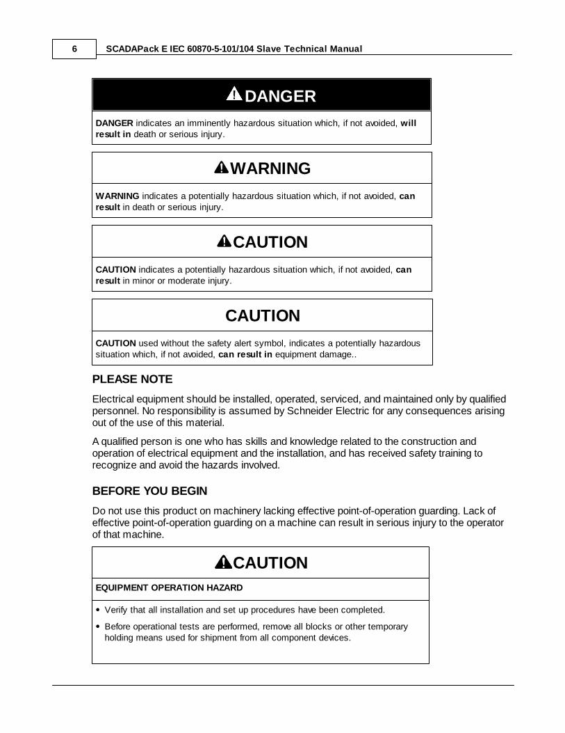
Read these instructions carefully, and look at the equipment to become familiar with thedevice before trying to install, operate, or maintain it. The following special messages mayappear throughout this documentation or on the equipment to warn of potential hazards or tocall attention to information that clarifies or simplifies a procedure.
The addition of this symbol to a Danger or Warning safety labelindicates that an electrical hazard exists, which will result in personalinjury if the instructions are not followed.
This is the safety alert symbol. It is used to alert you to potentialpersonal injury hazards. Obey all safety messages that follow thissymbol to avoid possible injury or death.
SCADAPack E IEC 60870-5-101/104 Slave Technical Manual6
DANGER
DANGER indicates an imminently hazardous situation which, if not avoided, willresult in death or serious injury.
WARNING
WARNING indicates a potentially hazardous situation which, if not avoided, canresult in death or serious injury.
CAUTION
CAUTION indicates a potentially hazardous situation which, if not avoided, canresult in minor or moderate injury.
CAUTION
CAUTION used without the safety alert symbol, indicates a potentially hazardoussituation which, if not avoided, can result in equipment damage..
PLEASE NOTE
Electrical equipment should be installed, operated, serviced, and maintained only by qualifiedpersonnel. No responsibility is assumed by Schneider Electric for any consequences arisingout of the use of this material.
A qualified person is one who has skills and knowledge related to the construction andoperation of electrical equipment and the installation, and has received safety training torecognize and avoid the hazards involved.
BEFORE YOU BEGIN
Do not use this product on machinery lacking effective point-of-operation guarding. Lack ofeffective point-of-operation guarding on a machine can result in serious injury to the operatorof that machine.
CAUTION
EQUIPMENT OPERATION HAZARD
Verify that all installation and set up procedures have been completed.
Before operational tests are performed, remove all blocks or other temporaryholding means used for shipment from all component devices.
IEC 60870-5-101/104 Slave Technical 7
Remove tools, meters, and debris from equipment.
Failure to follow these instructions can result in injury or equipmentdamage.
Follow all start-up tests recommended in the equipment documentation. Store all equipmentdocumentation for future references.
Software testing must be done in both simulated and real environments.
Verify that the completed system is free from all short circuits and grounds, except thosegrounds installed according to local regulations (according to the National Electrical Code inthe U.S.A, for instance). If high-potential voltage testing is necessary, followrecommendations in equipment documentation to prevent accidental equipment damage.
Before energizing equipment:
Remove tools, meters, and debris from equipment.
Close the equipment enclosure door.
Remove ground from incoming power lines.
Perform all start-up tests recommended by the manufacturer.
OPERATION AND ADJUSTMENTS
The following precautions are from the NEMA Standards Publication ICS 7.1-1995 (Englishversion prevails):
Regardless of the care exercised in the design and manufacture of equipment or in theselection and ratings of components, there are hazards that can be encountered if suchequipment is improperly operated.
It is sometimes possible to misadjust the equipment and thus produce unsatisfactory orunsafe operation. Always use the manufacturer’s instructions as a guide for functionaladjustments. Personnel who have access to these adjustments should be familiar with theequipment manufacturer’s instructions and the machinery used with the electricalequipment.
Only those operational adjustments actually required by the operator should be accessibleto the operator. Access to other controls should be restricted to prevent unauthorizedchanges in operating characteristics.
3 Overview
This document describes the functionality of the SCADAPack E RTU communication drivers for IEC60870-5-101 and IEC 60870-5-104 communication protocols.
This document should be read in conjunction with the SCADAPack E IEC 60870-5-101 SlaveInteroperability document and SCADAPack E IEC 60870-5-104 Slave Interoperability document which
SCADAPack E IEC 60870-5-101/104 Slave Technical Manual8
describe the level of support provided by the SCADAPack E RTU, and the IEC 60870-5-101 Companionstandard and IEC 60870-5-104 Companion standard which describe the transmission protocol forTelecontrol equipment and systems.
The IEC 60870-5-101 Slave driver in the RTU is implemented in accordance with the IEC 60870-5-101Companion standard, as well as the standards defined in IEC 60870-5-1 to IEC 60870-5-5.
The IEC 60870-5-104 Slave driver in the RTU is implemented in accordance with the IEC 60870-5-101and IEC 60870-5-104 Companion standards, as well as the standards defined in IEC 60870-5-3 to IEC60870-5-5.
As well as standard SCADA data reporting functions, the IEC 60870-5-101 and IEC 60870-5-104 driversprovide slave file transfer functionality to support remote operations such as Configuration file transfer,ISaGRAF application transfer, firmware update, etc.
IEC 60870-5-101 and IEC 60870-5-104 functionality is only activated on SCADAPack E RTUs whenappropriately licensed. Both protocols are licensed together.
Requests for licensing can be directed to:
IEC 60870-5-101/104 Slave Technical 9
4 Basic Features & Terminology
IEC 60870-5-101 protocol operates over serial connections. SCADAPack E RTUs can be configured tosupport IEC 60870-5-101 protocol as a Slave RTU device. IEC 60870-5-101 can operate on multipleserial ports.
IEC 60870-5-104 protocol operates over IP interfaces. SCADAPack E RTUs support IEC 60870-5-104over Ethernet interfaces and PPP serial interfaces as a Slave RTU device. IEC 60870-5-104 can operateon multiple IP interfaces.
It is highly recommended that the user be familiar with the IEC60870-5-101 and -104 internationalstandards prior to configuring the controller.
The SCADAPack E IEC 60870-5-101 / 104 driver provides a flexible interface to the RTU database andsystem facilities.
Terminology
The IEC 60870-5 protocols use a number of acronyms in describing data types and addressing.
The configuration of IEC 60870-5 features in the SCADAPack E RTU uses the following protocol terms:
ASDU Application ServiceData Unit
A data item at the application layer of a IEC 60870-5 protocol
ASDU TypeID
ASDU type IdentifierIEC 60870-5 protocol numeric identifier for the ASDU type
IOA Information ObjectAddress
The IEC index (address) of a data item
ASDU Type IDs are referred to by a Type ID number, being the protocol value of the ASDU Type ID (e.g.1) or sometimes by an alpha-numeric mnemonic (e.g. M_SP_NA_1). The ASDU values and mnemonicsare defined by the IEC international standard. See the SCADAPack E IEC60870-5-101 SlaveInteroperability Profile Document and SCADAPack E IEC60870-5-104 Slave Interoperability ProfileDocument for more information.
SCADAPack E IEC 60870-5-101/104 Slave Technical Manual10
5 Point Configuration
The section describes the individual point configurations that can be used to “identify” RTU points as IEC60870-5-101/104 Slave points, and how the different ASDUs correspond to RTU points attributes.
These include descriptions for input point types including double point configurations, control points,analog point scaling, and quality descriptor support.
This section makes reference to the SCADAPack E Configurator interface.
Consult the SCADAPack E Configuration File Format manual for detailed description of the relevantconfiguration file mnemonics for generation of RTU configuration files.
In general, the configurations for RTU database points for IEC 60870-5-101/104 protocol include thefollowing settings:
Information Object Address (IOA) - this is a separate configuration parameter from the DNP3 pointnumber but has a similar purpose for IEC 60870-5 protocol
Application Service Data Unit (ASDU) Type - this is a separate configuration parameter from the DNP3static object type but has a similar purpose
Analog points also have an "Enable Cyclic Scan" check-box that makes analog point data available fora cyclic/periodic Station Interrogation.
The IEC 60870-5-101/104 standards define two data classes. Class 1 data is used for time tagged orspontaneously transmitted ASDUs. Class 2 data contains periodic / cyclic data.
The IEC data classes are NOT user selectable, and are not related to the DNP3 point configurations ofthe same name.
As such, the SCADAPack E configurations for Point Data Class do not apply to IEC 60870-5-101/104communications.
Point data is included by the RTU in the response to a periodic / cyclic requests, at the rates set by the Background Period and Cyclic Period times. Points with an IEC IOA address are returned in response tothe next station interrogation when the Background Period time has elapsed. Analog points set for "Enable Cyclic Scan" are also returned to the master when the Cyclic Period time has elapsed (usuallymuch more frequently than the Background Period).
Binary Points
Analog Points
Counter Points
IEC 60870-5-101/104 Slave Technical 11
5.1 Binary Point Configuration
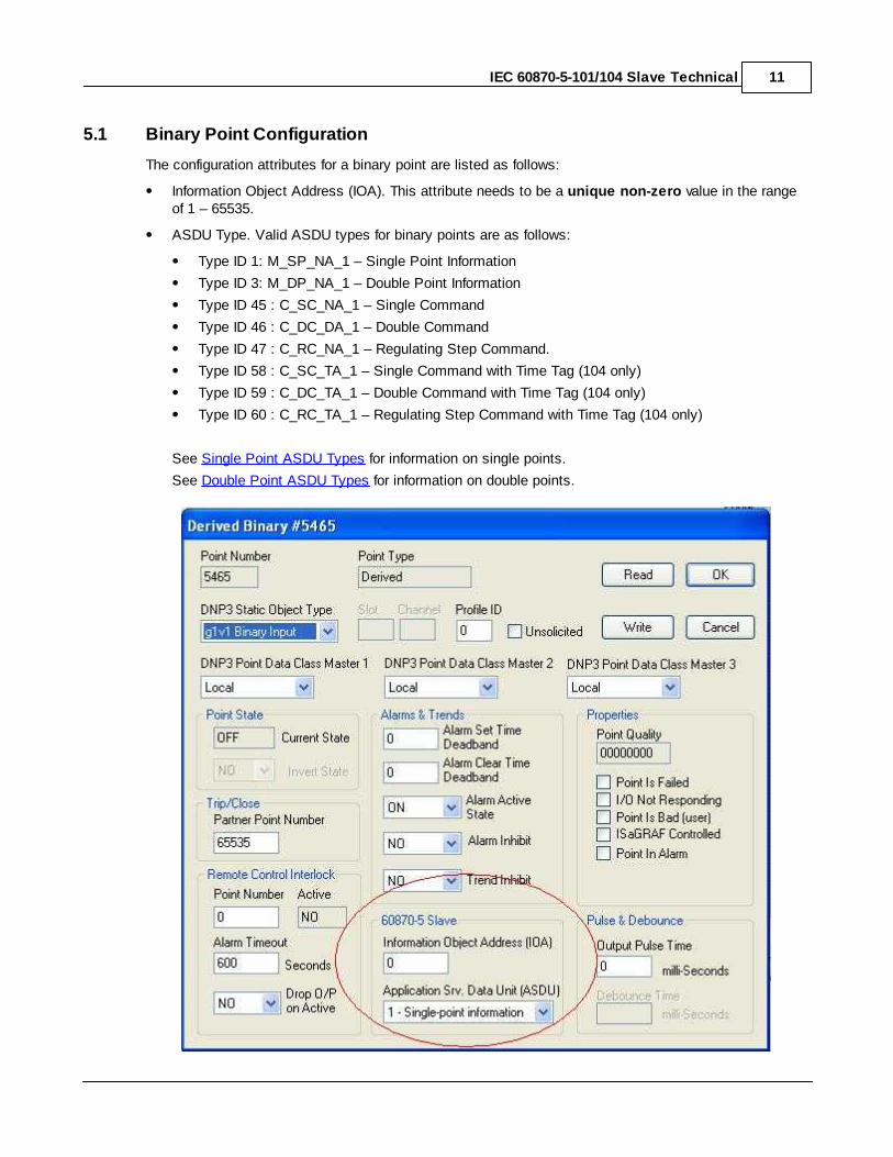
The configuration attributes for a binary point are listed as follows:
Information Object Address (IOA). This attribute needs to be a unique non-zero value in the rangeof 1 – 65535.
ASDU Type. Valid ASDU types for binary points are as follows:
Type ID 1: M_SP_NA_1 – Single Point Information
Type ID 3: M_DP_NA_1 – Double Point Information
Type ID 45 : C_SC_NA_1 – Single Command
Type ID 46 : C_DC_DA_1 – Double Command
Type ID 47 : C_RC_NA_1 – Regulating Step Command.
Type ID 58 : C_SC_TA_1 – Single Command with Time Tag (104 only)
Type ID 59 : C_DC_TA_1 – Double Command with Time Tag (104 only)
Type ID 60 : C_RC_TA_1 – Regulating Step Command with Time Tag (104 only)
See Single Point ASDU Types for information on single points.
See Double Point ASDU Types for information on double points.

SCADAPack E IEC 60870-5-101/104 Slave Technical Manual12
Figure 5.4: Binary Point IEC Configurations

IEC 60870-5-101/104 Slave Technical 13
5.1.1 Single Point ASDU Types
Single point types ASDUs include Information Objects that reference a single Information ObjectAddress (IOA) which maps to a single SCADAPack E binary configuration point.
ASDU Type ID 1: M_SP_NA_1 - Single Point InformationFor ASDU Type ID 1 (Single Point Information), the value reported in the SPI of the Information Object isderived from the Current State of the binary point.
The IV bit of the quality descriptor (SIQ) is mapped to the Point Is Failed property of the binaryconfiguration point.
The NT, SB, and BL bits in the quality descriptor (SIQ) are not referenced.
ASDU Type ID 45: C_SC_DA_1 - Single CommandThe following table determines how a binary output point is controlled for Single Command type ASDU.
Table 7.1: ASDU Type ID 45 : Control State Table
ASDU 45RTU Binary
OutputSingle
CommandState (SCS)
SCSDescription
Qualifier ofCommand
(QU)
QU Description
0 OFF
0 No additionaldefinition
Latched OFF
1 Short pulseduration
Pulsed ON (Short)
2 Long pulse duration Pulsed ON (Long)
3 Persistent Output Latched OFF
1 ON
0 No additionaldefinition
Latched ON
1 Short pulseduration
Pulsed ON (Short)
2 Long pulse duration Pulsed ON (Long)
3 Persistent Output Latched ON
ASDU Type ID 58: C_SC_TA_1 - Single Command with Time Tag (-104 only)As for Type ID 45 except that the command is time tagged and only valid for the Command Age time.
Also see Command Age.
SCADAPack E IEC 60870-5-101/104 Slave Technical Manual14
5.1.2 Double Point ASDU Types
When a binary point is configured as a double point ASDU type, i.e. Type ID 3 or Type ID 46, two RTUconfiguration points are referenced with contiguous database point numbers.
The configuration point with the lower index point number needs to be configured with the IEC IOA andthe correct ASDU type.
The other point (i.e. the numerically next database point number) does NOT require any IEC 60870-5-101/104 configurations, and need NOT have an assigned IOA, otherwise a configuration error is flaggedusing the system error code point. See Applying Configurations.
Section Double Point ASDU Types includes examples of double point configurations.
ASDU Type ID 3: M_DP_NA_1 - Double Point Information, ASDU Type ID 60: C_RC_TA_1 -
Regulating Step Command with Time Tag (104 only), & ASDU Type ID 59: C_DC_TA_1 - Double
Command with Time Tag (104 only)
ASDU TypeID 46: C_DC_DA_1 - Double Command
ASDU TypeID 47: C_RC_NA_1 - Regulating Step Command
IEC 60870-5-101/104 Slave Technical 15
5.1.2.1 ASDU Type ID 3, 60, & 59
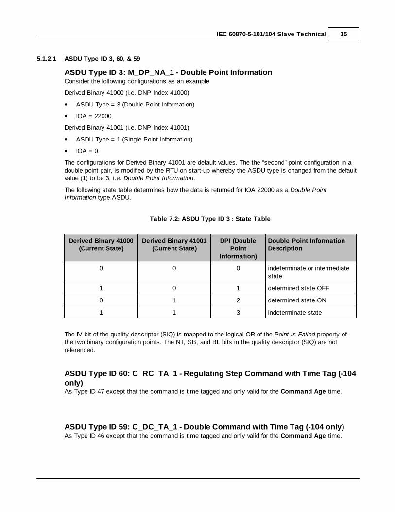
ASDU Type ID 3: M_DP_NA_1 - Double Point InformationConsider the following configurations as an example
Derived Binary 41000 (i.e. DNP Index 41000)
ASDU Type = 3 (Double Point Information)
IOA = 22000
Derived Binary 41001 (i.e. DNP Index 41001)
ASDU Type = 1 (Single Point Information)
IOA = 0.
The configurations for Derived Binary 41001 are default values. The the “second” point configuration in adouble point pair, is modified by the RTU on start-up whereby the ASDU type is changed from the defaultvalue (1) to be 3, i.e. Double Point Information.
The following state table determines how the data is returned for IOA 22000 as a Double PointInformation type ASDU.
Table 7.2: ASDU Type ID 3 : State Table
Derived Binary 41000(Current State)
Derived Binary 41001(Current State)
DPI (DoublePoint
Information)
Double Point InformationDescription
0 0 0 indeterminate or intermediatestate
1 0 1 determined state OFF
0 1 2 determined state ON
1 1 3 indeterminate state
The IV bit of the quality descriptor (SIQ) is mapped to the logical OR of the Point Is Failed property ofthe two binary configuration points. The NT, SB, and BL bits in the quality descriptor (SIQ) are notreferenced.
ASDU Type ID 60: C_RC_TA_1 - Regulating Step Command with Time Tag (-104only)As Type ID 47 except that the command is time tagged and only valid for the Command Age time.
ASDU Type ID 59: C_DC_TA_1 - Double Command with Time Tag (-104 only)As Type ID 46 except that the command is time tagged and only valid for the Command Age time.
SCADAPack E IEC 60870-5-101/104 Slave Technical Manual16
5.1.2.2 ASDU Type ID 46
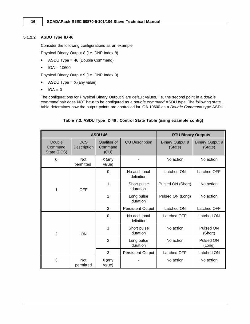
Consider the following configurations as an example
Physical Binary Output 8 (i.e. DNP Index 8)
ASDU Type = 46 (Double Command)
IOA = 10600
Physical Binary Output 9 (i.e. DNP Index 9)
ASDU Type = X (any value)
IOA = 0
The configurations for Physical Binary Output 9 are default values, i.e. the second point in a doublecommand pair does NOT have to be configured as a double command ASDU type. The following statetable determines how the output points are controlled for IOA 10600 as a Double Command type ASDU.
Table 7.3: ASDU Type ID 46 : Control State Table (using example config)
ASDU 46 RTU Binary Outputs
DoubleCommand
State (DCS)
DCSDescription
Qualifier ofCommand
(QU)
QU Description Binary Output 8(State)
Binary Output 9(State)
0 Notpermitted
X (anyvalue)
- No action No action
1 OFF
0 No additionaldefinition
Latched ON Latched OFF
1 Short pulseduration
Pulsed ON (Short) No action
2 Long pulseduration
Pulsed ON (Long) No action
3 Persistent Output Latched ON Latched OFF
2 ON
0 No additionaldefinition
Latched OFF Latched ON
1 Short pulseduration
No action Pulsed ON(Short)
2 Long pulseduration
No action Pulsed ON(Long)
3 Persistent Output Latched OFF Latched ON
3 Notpermitted
X (anyvalue)
- No action No action
IEC 60870-5-101/104 Slave Technical 17
5.1.2.3 ASDU Type ID 47
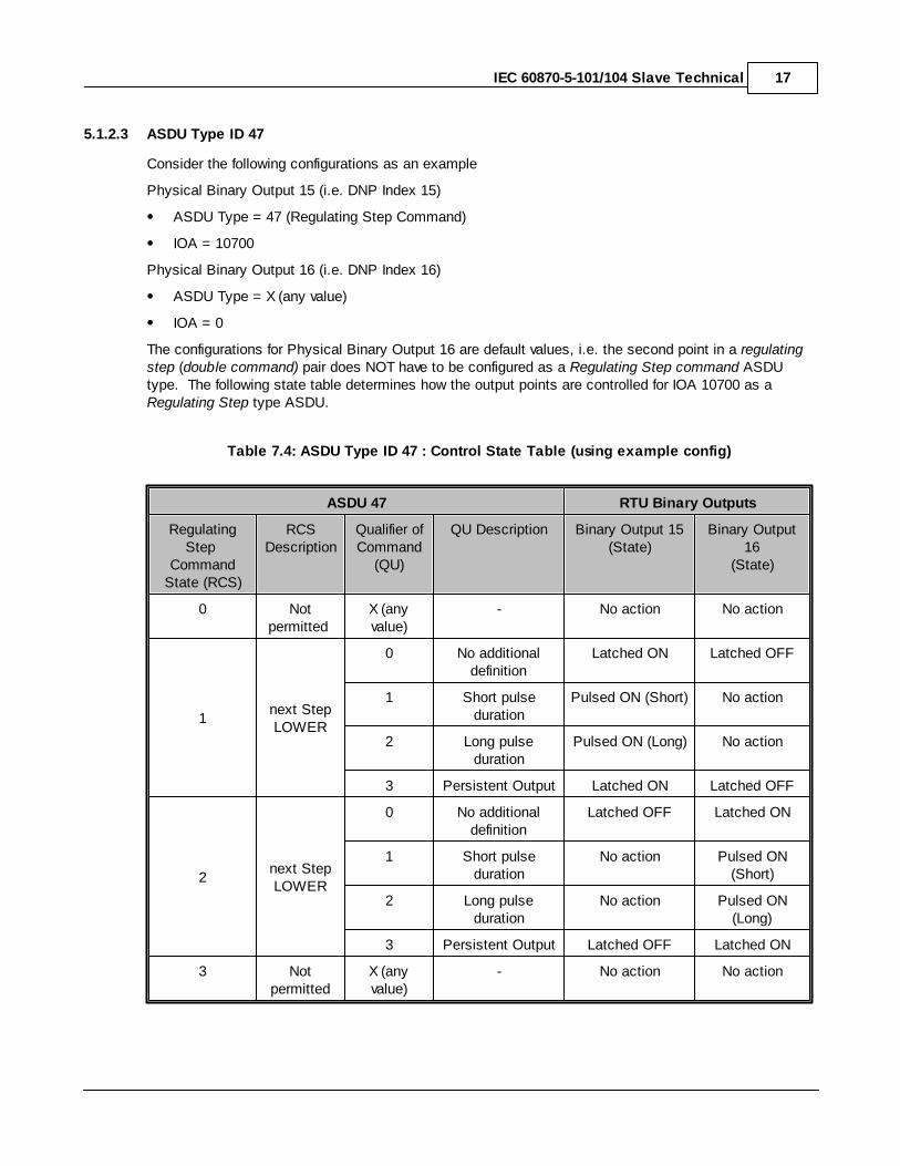
Consider the following configurations as an example
Physical Binary Output 15 (i.e. DNP Index 15)
ASDU Type = 47 (Regulating Step Command)
IOA = 10700
Physical Binary Output 16 (i.e. DNP Index 16)
ASDU Type = X (any value)
IOA = 0
The configurations for Physical Binary Output 16 are default values, i.e. the second point in a regulatingstep (double command) pair does NOT have to be configured as a Regulating Step command ASDUtype. The following state table determines how the output points are controlled for IOA 10700 as a Regulating Step type ASDU.
Table 7.4: ASDU Type ID 47 : Control State Table (using example config)
ASDU 47 RTU Binary Outputs
RegulatingStep
CommandState (RCS)
RCSDescription
Qualifier ofCommand
(QU)
QU Description Binary Output 15(State)
Binary Output16
(State)
0 Notpermitted
X (anyvalue)
- No action No action
1next StepLOWER
0 No additionaldefinition
Latched ON Latched OFF
1 Short pulseduration
Pulsed ON (Short) No action
2 Long pulseduration
Pulsed ON (Long) No action
3 Persistent Output Latched ON Latched OFF
2next StepLOWER
0 No additionaldefinition
Latched OFF Latched ON
1 Short pulseduration
No action Pulsed ON(Short)
2 Long pulseduration
No action Pulsed ON(Long)
3 Persistent Output Latched OFF Latched ON
3 Notpermitted
X (anyvalue)
- No action No action
SCADAPack E IEC 60870-5-101/104 Slave Technical Manual18
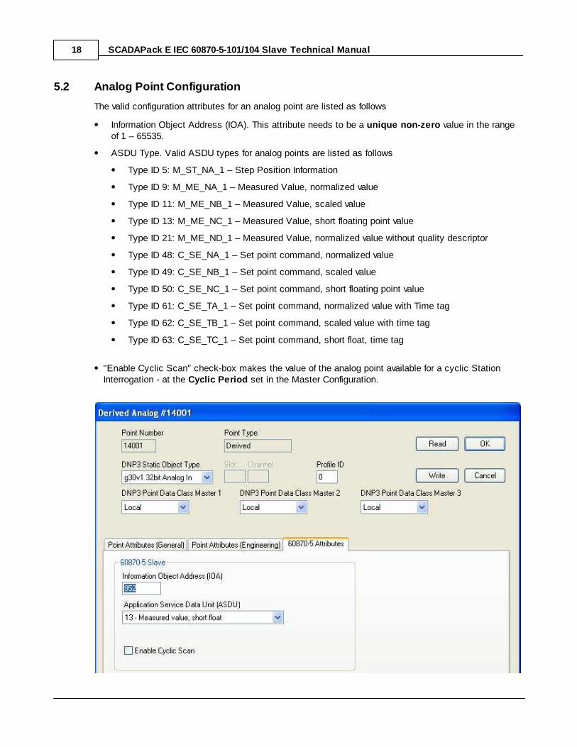
5.2 Analog Point Configuration
The valid configuration attributes for an analog point are listed as follows
Information Object Address (IOA). This attribute needs to be a unique non-zero value in the rangeof 1 – 65535.
ASDU Type. Valid ASDU types for analog points are listed as follows
Type ID 5: M_ST_NA_1 – Step Position Information
Type ID 9: M_ME_NA_1 – Measured Value, normalized value
Type ID 11: M_ME_NB_1 – Measured Value, scaled value
Type ID 13: M_ME_NC_1 – Measured Value, short floating point value
Type ID 21: M_ME_ND_1 – Measured Value, normalized value without quality descriptor
Type ID 48: C_SE_NA_1 – Set point command, normalized value
Type ID 49: C_SE_NB_1 – Set point command, scaled value
Type ID 50: C_SE_NC_1 – Set point command, short floating point value
Type ID 61: C_SE_TA_1 – Set point command, normalized value with Time tag
Type ID 62: C_SE_TB_1 – Set point command, scaled value with time tag
Type ID 63: C_SE_TC_1 – Set point command, short float, time tag
"Enable Cyclic Scan" check-box makes the value of the analog point available for a cyclic StationInterrogation - at the Cyclic Period set in the Master Configuration.

IEC 60870-5-101/104 Slave Technical 19
Figure 5.5: Analog Point IEC Configuration
SCADAPack E IEC 60870-5-101/104 Slave Technical Manual20
5.2.1 Analog Point ASDU Types
Analog configuration points may be identified as scaled, normalized or floating points in IEC 60870-5-101slave responses.
The following sections describe how the RTU point’s current value is represented in these ASDU types.
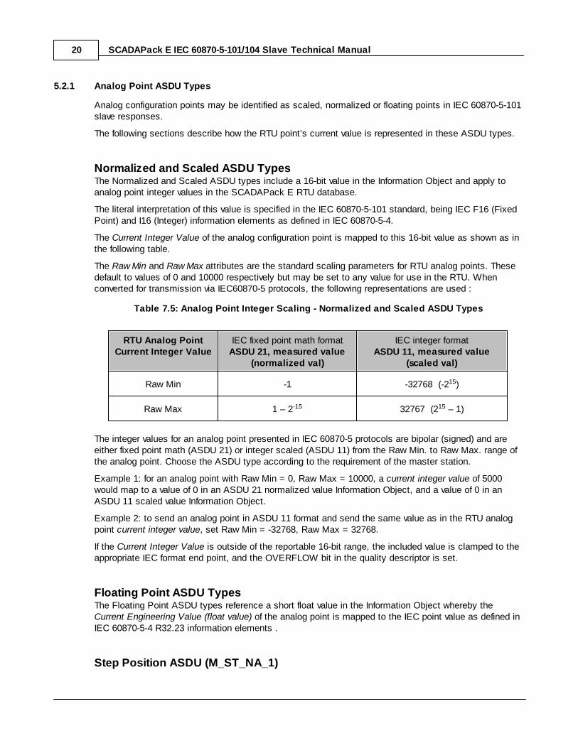
Normalized and Scaled ASDU TypesThe Normalized and Scaled ASDU types include a 16-bit value in the Information Object and apply toanalog point integer values in the SCADAPack E RTU database.
The literal interpretation of this value is specified in the IEC 60870-5-101 standard, being IEC F16 (FixedPoint) and I16 (Integer) information elements as defined in IEC 60870-5-4.
The Current Integer Value of the analog configuration point is mapped to this 16-bit value as shown as inthe following table.
The Raw Min and Raw Max attributes are the standard scaling parameters for RTU analog points. Thesedefault to values of 0 and 10000 respectively but may be set to any value for use in the RTU. Whenconverted for transmission via IEC60870-5 protocols, the following representations are used :
Table 7.5: Analog Point Integer Scaling - Normalized and Scaled ASDU Types
RTU Analog PointCurrent Integer Value
IEC fixed point math formatASDU 21, measured value
(normalized val)
IEC integer formatASDU 11, measured value
(scaled val)
Raw Min -1 -32768 (-215)
Raw Max 1 – 2-15 32767 (215 – 1)
The integer values for an analog point presented in IEC 60870-5 protocols are bipolar (signed) and areeither fixed point math (ASDU 21) or integer scaled (ASDU 11) from the Raw Min. to Raw Max. range ofthe analog point. Choose the ASDU type according to the requirement of the master station.
Example 1: for an analog point with Raw Min = 0, Raw Max = 10000, a current integer value of 5000would map to a value of 0 in an ASDU 21 normalized value Information Object, and a value of 0 in anASDU 11 scaled value Information Object.
Example 2: to send an analog point in ASDU 11 format and send the same value as in the RTU analogpoint current integer value, set Raw Min = -32768, Raw Max = 32768.
If the Current Integer Value is outside of the reportable 16-bit range, the included value is clamped to theappropriate IEC format end point, and the OVERFLOW bit in the quality descriptor is set.
Floating Point ASDU TypesThe Floating Point ASDU types reference a short float value in the Information Object whereby the Current Engineering Value (float value) of the analog point is mapped to the IEC point value as defined inIEC 60870-5-4 R32.23 information elements .
Step Position ASDU (M_ST_NA_1)

IEC 60870-5-101/104 Slave Technical 21
The Current Integer Value of the analog point is directly mapped to the 7-bit Value included on theInformation Object. If the Current Integer Value is outside of the valid Value range, i.e. -64 to 63, theOVERFLOW bit in the quality descriptor (QDS) is set. The Transient bit in the VTI field is notreferenced.
Quality Descriptor SupportFor each of the supported analog type ASDUs, there is limited support for quality descriptor fields.
The IV bit of the quality descriptor (QDS) is mapped to the Point Is Failed property of the analogconfiguration point.
The OV bit is set if the current value of the point is beyond the reportable range according to thespecific ASDU type.
The NT, SB, and BL bits in the quality descriptor (QDS) are not referenced.
SCADAPack E IEC 60870-5-101/104 Slave Technical Manual22
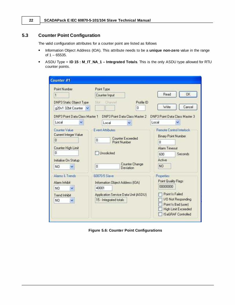
5.3 Counter Point Configuration
The valid configuration attributes for a counter point are listed as follows
Information Object Address (IOA). This attribute needs to be a unique non-zero value in the rangeof 1 – 65535.
ASDU Type = ID 15 : M_IT_NA_1 – Integrated Totals. This is the only ASDU type allowed for RTUcounter points.
Figure 5.6: Counter Point Configurations
IEC 60870-5-101/104 Slave Technical 23
5.3.1 Counter Point ASDU Types
The counter points may only be configured as ASDU type 15, i.e. M_IT_NA_1 (Integrated Totals). Thecounter values reported in this ASDU type are frozen values. Counter (integrated total) values areretrieved from the RTU using Counter Interrogation Commands. For more details regarding countersupport in the RTU’s 60870-5-101 Slave driver, refer to Section ASDU TypeID 100, 101, 103, 104, 105, &107 (ASDU Type ID 101 : C_CI_NA_1 – Counter Interrogation Command).
ASDU Type ID 15: M_IT_NA_1 - Integrated TotalsThe information object in the Integrated Totals ASDU includes a signed 32-bit value, which is identifiedas a Binary Counter Reading (BCR). The Current Integer Value of the counter point (unsigned 32-bit) iscopied into the cached frozen value for the particular Information Object Address (IOA) when a “CounterFreeze” request is made via a Counter Interrogation Command. For every COUNTER FEEZE commandreceived from the relevant Master, the sequence number (SQ) for that IOA is incremented.
The invalid (IV) bit included in the information object is mapped to the Point Is Failed property of thecounter configuration point.
The Counter Adjusted (CA) bit included in the information object is set if the counter value has beenreset due to a COUNTER FREEZE request, and is only asserted for the first READ after the COUNTERFREEZE. The CA bit is also set on RTU start-up if the Counter Reset attribute of the counterconfiguration point was set to TRUE (see the SCADAPack E RTU Configuration Technical ReferenceManual for more details regarding counter point attributes).
The Carry (CY) bit is not referenced by the RTU’s 60870-5-101 Slave driver.
SCADAPack E IEC 60870-5-101/104 Slave Technical Manual24
6 System Configuration
The primary interface for configuring the SCADAPack E RTU IEC 60870-5-101/104 Slave is theSCADAPack E Configurator software.
IEC60870-5-101 Serial Port Configurations
IEC 60870-5-101 / -104 System Configurations
Applying Configurations & Configuration Diagnostics
Compatibility between SCADAPack E or SCADAPack E Configurator versions7.84 (and newer) and previous versions. In previous versions, 7.83 or earlier, the ASDU Size, ASDU Address and the IOA Size did not usesperate system points.These parameters were set to default values and were not configurable. WithSCADAPack E firmware version 7.84 and SCADAPack E Configurator version 7.84 the ASDU size andaddress and the IOA size have individual system points and are user configurable. When upgrading toSCADAPack E or SCADAPack E Configurator versions 7.84 and newer some important compatibilityquestions need to be considered. See the Compatibility between SCADAPack E or SCADAPack EConfigurator versions 7.84 (and newer) and previous versions topic for full details.
IEC 60870-5-101/104 Slave Technical 25
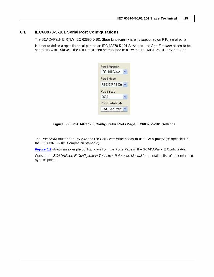
6.1 IEC60870-5-101 Serial Port Configurations
The SCADAPack E RTU's IEC 60870-5-101 Slave functionality is only supported on RTU serial ports.
In order to define a specific serial port as an IEC 60870-5-101 Slave port, the Port Function needs to beset to “IEC--101 Slave”. The RTU must then be restarted to allow the IEC 60870-5-101 driver to start.
Figure 5.2: SCADAPack E Configurator Ports Page IEC60870-5-101 Settings
The Port Mode must be to RS-232 and the Port Data Mode needs to use Even parity (as specified inthe IEC 60870-5-101 Companion standard).
Figure 5.2 shows an example configuration from the Ports Page in the SCADAPack E Configurator.
Consult the SCADAPack E Configuration Technical Reference Manual for a detailed list of the serial portsystem points.
SCADAPack E IEC 60870-5-101/104 Slave Technical Manual26
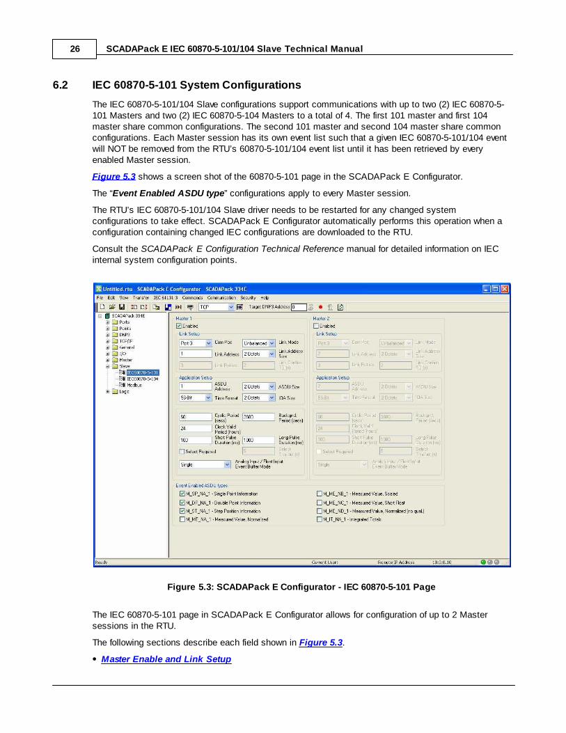
6.2 IEC 60870-5-101 System Configurations
The IEC 60870-5-101/104 Slave configurations support communications with up to two (2) IEC 60870-5-101 Masters and two (2) IEC 60870-5-104 Masters to a total of 4. The first 101 master and first 104master share common configurations. The second 101 master and second 104 master share commonconfigurations. Each Master session has its own event list such that a given IEC 60870-5-101/104 eventwill NOT be removed from the RTU’s 60870-5-101/104 event list until it has been retrieved by everyenabled Master session.
Figure 5.3 shows a screen shot of the 60870-5-101 page in the SCADAPack E Configurator.
The “Event Enabled ASDU type” configurations apply to every Master session.
The RTU’s IEC 60870-5-101/104 Slave driver needs to be restarted for any changed systemconfigurations to take effect. SCADAPack E Configurator automatically performs this operation when aconfiguration containing changed IEC configurations are downloaded to the RTU.
Consult the SCADAPack E Configuration Technical Reference manual for detailed information on IECinternal system configuration points.
Figure 5.3: SCADAPack E Configurator - IEC 60870-5-101 Page
The IEC 60870-5-101 page in SCADAPack E Configurator allows for configuration of up to 2 Mastersessions in the RTU.
The following sections describe each field shown in Figure 5.3.
Master Enable and Link Setup

IEC 60870-5-101/104 Slave Technical 27
Application Setup
Background Period, Cyclic Period Clock Period and Short & Long Pulse Duration
Event Enabled ASDU Types
System Event Capacity
System Point Listing
SCADAPack E IEC 60870-5-101/104 Slave Technical Manual28
6.2.1 Master Enable and Link Setup
Master EnabledThe Master Enabled checkbox determines whether the respective slave session (for the specifiedMaster address) is enabled in the RTU. The default configurations are listed as follows
Master 1 Enabled = ON
Master 2 Enabled = OFF.
If a given Master session is NOT enabled, the RTU will NOT respond to any messages received on thespecified COM port for that Master session.
Com PortThe Com Port field specifies the serial COM port on the RTU for the relevant Master session. For thisconfiguration to be valid, the specified Port needs to also be configured with a PORT FUNCTION of “IEC--101 Slave” on the SCADAPack E Configurator Ports Page.
If both Master sessions are enabled, they can use the same COM Port only if they are both running IEC60870-5-101 Unbalanced Mode. (See Link Mode below).
Link AddressThe Link Address configuration field is used to assign the Link addresses for the relevant Mastersession. The valid range of values for this configuration field is dependent on the Link Address Size field(see Section Link Address Size below), i.e. 0 – 255 for 1 octet Link Address size and 0 – 65535 for 2octet Link Address size.
Link Retries
The Link Retries configuration field is only relevant when in Balanced mode.
This field specifies the number of link retries for a given message before reporting that particularmessage unsuccessful. The default value for this field is 3. Valid values are 0 to 65535.
This field is only used for -101 slave sessions as the -104 protocol has no IEC link layer.
Link Mode
The Link Mode configuration field sets the Link Mode for the respective Master session.
The Link Mode may be set to one of the following Options
Unbalanced (default)
Balanced.
When operating in Unbalanced mode, communications are initiated by the Master whereby the Mastertypically makes frequent requests for data (Class 1 or Class 2 polls).
When operating in Balanced Mode, the Master does NOT initiate communications, and data is reportedby the RTU as required by its configurations. In this mode, the RTU initiates communications typicallywith a Request Link Status message.
Irrespective of the Link Mode, the RTU (IEC 60870-5-101 Slave) presents data in responses accordingto its configurations.
IEC 60870-5-101/104 Slave Technical 29
SCADAPack E data configured with a valid IEC IOA is reported every Background Period. SeeBackground Period
"Cyclic” data is reported every Cyclic Period. See Section Cyclic Period
Event data is reported spontaneously as required.
This field is only used for -101 slave sessions. The -104 protocol has no IEC protocol link layer.
Link Address Size
The Link Address Size configuration field sets the size of the Link Address field specified in Linktransactions for the relevant Master session.
The Link Address may be set to one of the following options
None (invalid in Unbalanced mode)
1 Octet
2 Octets (default).
This field is only used for -101 slave sessions as the -104 protocol has no IEC link layer.
Link Confirm Time Out
The Link Confirm Timeout configuration field is specified in seconds, and is only relevant when inBalanced mode.
This field specifies the time (in seconds) that the RTU’s IEC 60870-5-101 Slave driver will wait for aresponse to a Link message before issuing a retry. The default value for this field is 2 seconds. Validvalues are 0 to 65535.
This field is only used for -101 slave sessions as the -104 protocol has no IEC link layer.
SCADAPack E IEC 60870-5-101/104 Slave Technical Manual30
6.2.2 Application Setup
ASDU AddressThe ASDU Address configuration field is used to assign the ASDU addresses for the relevant Mastersession. The valid range of values for this configuration field is dependent on the ASDU Address Sizefield (see Section ASDU Address Size below), i.e. 1 – 255 for 1 octet ASDU Address size and 1 –65535 for 2 octet ASDU Address size.
Time FormatThe Time Format configuration field determines which timestamp format is included with generatedevent data. The Time Format may be set to one of the following options
56-bit (default)
24-bit
The 56-bit Time Format is an absolute time format, whereas the 24-bit Time Format is an incrementaltime format that only specifies minutes and milliseconds.
This field is only used for 101 slave sessions, as the -104 protocol uses 56-bit time format.
ASDU SizeThe ADSU Size configuration field sets the size of the ASDU Address field for the relevant Mastersession.
The ASDU Address Size may be set to one of the following options:
1 Octet
2 Octets (default)
This field is only used for -101 slave sessions as for the -104 protocol; it has a fixed length of 2 octets(bytes).
The ASDU size must be set to the same value in both the master station and the slave station forcommunication to work between the stations.
IOA SizeThe IOA Size configuration field sets the size of the IOA field for the relevant points.
The IOA Size may be set to one of the following options:
1 Octet
2 Octets (default)
3 Octets
This field is only used for -101 slave sessions as for the -104 protocol; it has a fixed length of 3 octets(bytes).
A value of 0 is not valid for -101 or -104 protocols. Writing a 0 to the IOA Size will result in:
1. ASDU Address being set to the same value as the configured Link Address for the master
2. ASDU Address Size being set to the default value of 2 for the master
3. IOA size set to the default value of 2 for the master
It should be noted that a value of 0 will not remain visible in this status point as it will be changed to a

IEC 60870-5-101/104 Slave Technical 31
value of 2. Accepting a value of 0 is being permitted for compatibility reasons. Please refer to thecompatibility section for more details.
The IOA size must be set the to the same value in both the master station and the slave station forcommunication to work between the stations.

SCADAPack E IEC 60870-5-101/104 Slave Technical Manual32
6.2.3 Background Period, Cyclic Period, Clock Period and Short & Long Pulse Duration
Cyclic PeriodThe Cyclic Period configuration field is specified in seconds and determines the rate at which Cyclicdata is returned by the RTU’s IEC 60870-5-101 driver.
Cyclic data is identified as those analog RTU configuration points which have a valid non-zeroInformation Object Address, and whose Enable Cyclic Scan attribute is set to TRUE. See Analog PointAttributes.
This default value for this field is 60 seconds.
Background PeriodThe Background Period configuration field is specified in seconds and determines the rate at whichBackground data is returned by the RTU’s IEC 60870-5-101/104 driver.
Background data is defined as RTU configuration points which have a valid non-zero Information ObjectAddress (IOA) and a valid ASDU Type. This default value for this field is 3600 seconds.
Clock Valid PeriodThe Clock Valid Period field sets the period of time for which timestamps are considered valid afterreceiving a clock synchronization command.
When the RTU’s IEC 60870-5-101/104 driver starts, timestamps issued are identified as invalid until aclock synchronization command has been received for that specific master session.
The default value for this field is 24 hours.
Short Pulse DurationThe Short Pulse Duration configuration field is specified in milliseconds and determines the PULSEON duration utilized when a valid binary control is received by the RTU, when the qualifier ofcommand for the relevant control object specifies Short Pulse Duration. This default value for this field is100 milliseconds.
Long Pulse DurationThe Long Pulse Duration configuration field is specified in milliseconds and determines the PULSE ONduration utilized when a valid binary control is received by the RTU, when the qualifier of command forthe relevant control object specifies Long Pulse Duration. This default value for this field is 1000milliseconds (1 second).
Select RequiredThe Select Required configuration field specifies whether or not a Select message is required before anExecute message in order to invoke the specified control.
If Select Required is set to TRUE, then a Select message needs to first be issued, and then followedby an Execute message.
The Execute message must be received within the Select Timeout (see Select Timeout below) periodfor the control to be invoked.
If Select Required is set to FALSE, then an Execute message only is required for the control to be
IEC 60870-5-101/104 Slave Technical 33
invoked.
Select TimeoutThe Execute command needs to be received within this period after the Select command is received.
The Select Timeout configuration field is specified in seconds.
If an Execute command (matching a recently received Select command) is not received within thisperiod then the control operation is aborted.
The default value for this field is 5 seconds.
SCADAPack E IEC 60870-5-101/104 Slave Technical Manual34
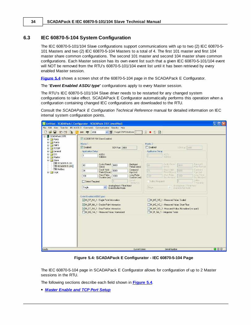
6.3 IEC 60870-5-104 System Configuration
The IEC 60870-5-101/104 Slave configurations support communications with up to two (2) IEC 60870-5-101 Masters and two (2) IEC 60870-5-104 Masters to a total of 4. The first 101 master and first 104master share common configurations. The second 101 master and second 104 master share commonconfigurations. Each Master session has its own event list such that a given IEC 60870-5-101/104 eventwill NOT be removed from the RTU’s 60870-5-101/104 event list until it has been retrieved by everyenabled Master session.
Figure 5.4 shows a screen shot of the 60870-5-104 page in the SCADAPack E Configurator.
The “Event Enabled ASDU type” configurations apply to every Master session.
The RTU’s IEC 60870-5-101/104 Slave driver needs to be restarted for any changed systemconfigurations to take effect. SCADAPack E Configurator automatically performs this operation when aconfiguration containing changed IEC configurations are downloaded to the RTU.
Consult the SCADAPack E Configuration Technical Reference manual for detailed information on IECinternal system configuration points.
Figure 5.4: SCADAPack E Configurator - IEC 60870-5-104 Page
The IEC 60870-5-104 page in SCADAPack E Configurator allows for configuration of up to 2 Mastersessions in the RTU.
The following sections describe each field shown in Figure 5.4.
Master Enable and TCP Port Setup
IEC 60870-5-101/104 Slave Technical 35
Application Setup
Background Period, Cyclic Period, Clock Period, Command Age and Short & Long PulseDuration
Event Enabled ASDU Types
System Event Capacity
System Point Listing
6.3.1 Master Enable and TCP Port Setup
Master EnabledThe Master Enabled checkbox determines whether the respective slave session (for the specifiedMaster address) is enabled in the RTU. The default configurations are listed as follows
Master 1 Enabled = ON
Master 2 Enabled = OFF.
If a given Master session is NOT enabled, the RTU will NOT respond to any messages received on thespecified COM port for that Master session.
TCP Port
The TCP Port configuration field sets the TCP port that the master sessions will listen to.
To establish a connection, a 104 Master will attempt a TCP connection to the appropriate IP addressusing the TCP port listed below.
104 Master session 1 listens on TCP port 2404
104 Master session 2 listens on TCP port 2405
SCADAPack E IEC 60870-5-101/104 Slave Technical Manual36
6.3.2 Application Setup
ASDU AddressThe ASDU Address configuration field is used to assign the ASDU addresses for the relevant Mastersession. The valid range of values for this configuration field is dependent on the ASDU Address Sizefield (see Section ASDU Address Size below), i.e. 1 – 255 for 1 octet ASDU Address size and 1 –65535 for 2 octet ASDU Address size.
6.3.3 Background Period, Cyclic Period, Clock Period, Command Age and Short & Long PulseDuration
Cyclic PeriodThe Cyclic Period configuration field is specified in seconds and determines the rate at which Cyclicdata is returned by the RTU’s IEC 60870-5-101 driver.
Cyclic data is identified as those analog RTU configuration points which have a valid non-zeroInformation Object Address, and whose Enable Cyclic Scan attribute is set to TRUE. See Analog PointAttributes.
This default value for this field is 60 seconds.
Background PeriodThe Background Period configuration field is specified in seconds and determines the rate at whichBackground data is returned by the RTU’s IEC 60870-5-101/104 driver.
Background data is defined as RTU configuration points which have a valid non-zero Information ObjectAddress (IOA) and a valid ASDU Type. This default value for this field is 3600 seconds.
Clock Valid PeriodThe Clock Valid Period field sets the period of time for which timestamps are considered valid afterreceiving a clock synchronization command.
When the RTU’s IEC 60870-5-101/104 driver starts, timestamps issued are identified as invalid until aclock synchronization command has been received for that specific master session.
The default value for this field is 24 hours.
Command AgeThe Command Age configuration field is specified in milliseconds.
Time tagged commands need to have a time tag no older than this period. If a time tagged command isolder than this period allows then the control operation is not taken. The default value for this field is30000 milliseconds.
Short Pulse DurationThe Short Pulse Duration configuration field is specified in milliseconds and determines the PULSEON duration utilized when a valid binary control is received by the RTU, when the qualifier ofcommand for the relevant control object specifies Short Pulse Duration. This default value for this field is
IEC 60870-5-101/104 Slave Technical 37
100 milliseconds.
Long Pulse DurationThe Long Pulse Duration configuration field is specified in milliseconds and determines the PULSE ONduration utilized when a valid binary control is received by the RTU, when the qualifier of command forthe relevant control object specifies Long Pulse Duration. This default value for this field is 1000milliseconds (1 second).
Select RequiredThe Select Required configuration field specifies whether or not a Select message is required before anExecute message in order to invoke the specified control.
If Select Required is set to TRUE, then a Select message needs to first be issued, and then followedby an Execute message.
The Execute message must be received within the Select Timeout (see Select Timeout below) periodfor the control to be invoked.
If Select Required is set to FALSE, then an Execute message only is required for the control to beinvoked.
Select TimeoutThe Execute command needs to be received within this period after the Select command is received.
The Select Timeout configuration field is specified in seconds.
If an Execute command (matching a recently received Select command) is not received within thisperiod then the control operation is aborted.
The default value for this field is 5 seconds.
SCADAPack E IEC 60870-5-101/104 Slave Technical Manual38
6.4 Event ASDUs
ASDUs without Time Tags
Each configuration point in the RTU may be configured as an IEC 60870-5-101/104 Slave point.
As there is no fixed limit to the number of configuration points that may exist in the RTU, the upperbound of system capacity is determined by available configuration memory and operational designconsiderations, e.g.. the baud rate of the connection and the correct background and cyclic periods forproper operation, which therefore determines the amount of data that may be transported using theavailable bandwidth.
ASDUs with Time Tags (Events)There is an event list created for each relevant ASDU type. The following is a list of ASDU types forwhich events may be generated by the SCADAPack E RTU:
ASDU Type ID 1: M_SP_NA_1 – Single Point Information
ASDU Type ID 3: M_DP_NA_1 – Double Point Information
ASDU Type ID 5: M_ST_NA_1 – Step Position Information
ASDU Type ID 9: M_ME_NA_1 – Measured Value, Normalized
ASDU Type ID 11: M_ME_NB_1 – Measured Value, Scaled
ASDU Type ID 13: M_ME_NC_1 – Measured Value, Short Float
ASDU Type ID 15: M_IT_NA_1 – Integrated totals
ASDU Type ID 21: M_ME_ND_1 – Measured Value, Normalized - no quality
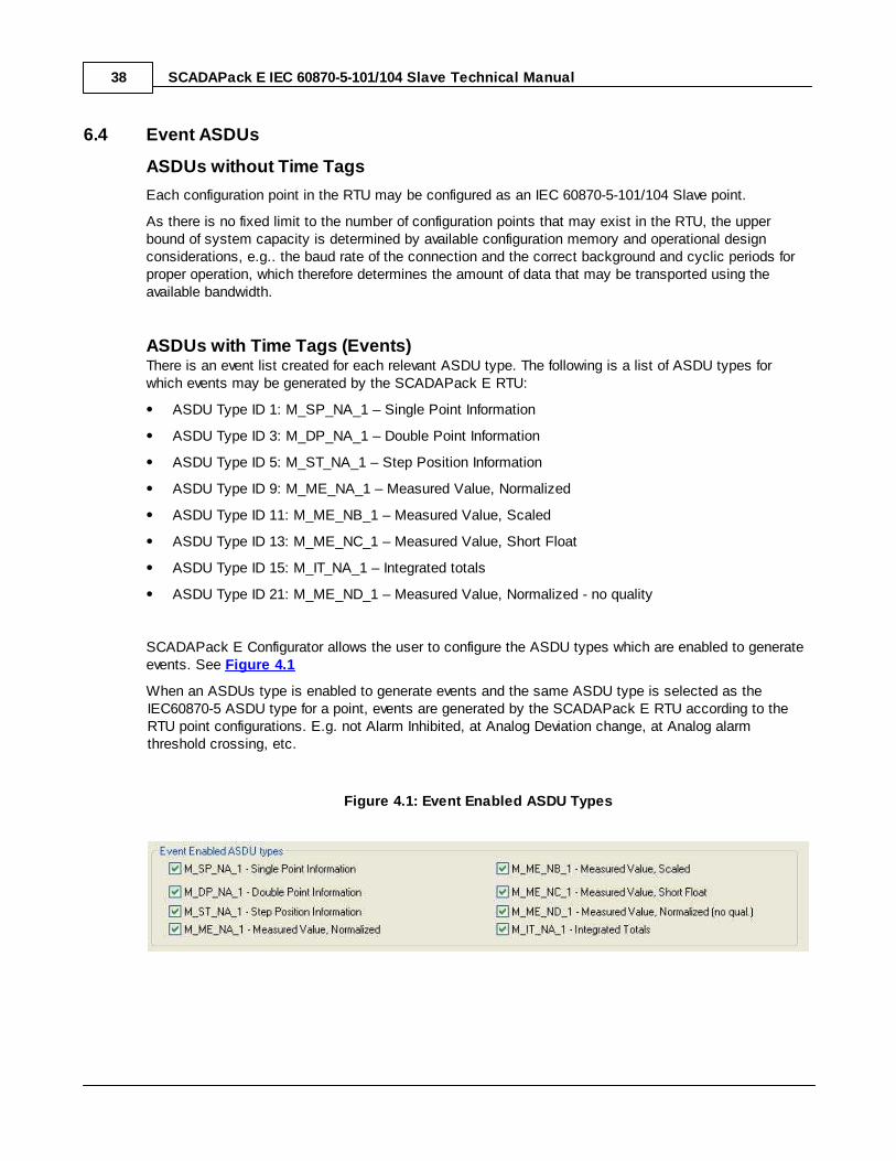
SCADAPack E Configurator allows the user to configure the ASDU types which are enabled to generateevents. See Figure 4.1
When an ASDUs type is enabled to generate events and the same ASDU type is selected as theIEC60870-5 ASDU type for a point, events are generated by the SCADAPack E RTU according to theRTU point configurations. E.g. not Alarm Inhibited, at Analog Deviation change, at Analog alarmthreshold crossing, etc.
Figure 4.1: Event Enabled ASDU Types
IEC 60870-5-101/104 Slave Technical 39
6.5 System Event Capacity
The RTU allows for a maximum of 500 events for each supported Event ASDU type.
As there are 7 supported Event ASDU types, total buffering capacity of SCADAPack E RTU is up to3500 IEC 60870-5 events.
If excess events are generated beyond the limit of 500 for a particular Event ASDU type, the oldestevents of that particular type are overwritten.
IEC 60870-5 events are volatile in the SCADAPack E RTU. I.e. they are not retained if the RTU isrestarted.
SCADAPack E IEC 60870-5-101/104 Slave Technical Manual40
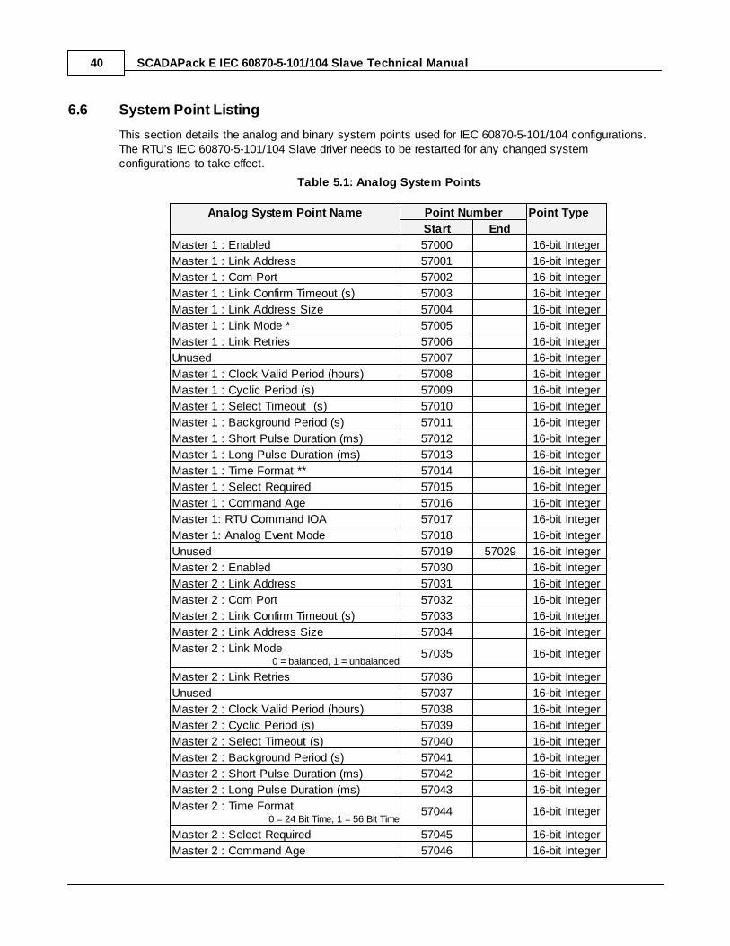
6.6 System Point Listing
This section details the analog and binary system points used for IEC 60870-5-101/104 configurations. The RTU’s IEC 60870-5-101/104 Slave driver needs to be restarted for any changed systemconfigurations to take effect.
Table 5.1: Analog System Points
Analog System Point Name Point Number Point Type
Start End
Master 1 : Enabled 57000 16-bit Integer
Master 1 : Link Address 57001 16-bit Integer
Master 1 : Com Port 57002 16-bit Integer
Master 1 : Link Confirm Timeout (s) 57003 16-bit Integer
Master 1 : Link Address Size 57004 16-bit Integer
Master 1 : Link Mode * 57005 16-bit Integer
Master 1 : Link Retries 57006 16-bit Integer
Unused 57007 16-bit Integer
Master 1 : Clock Valid Period (hours) 57008 16-bit Integer
Master 1 : Cyclic Period (s) 57009 16-bit Integer
Master 1 : Select Timeout (s) 57010 16-bit Integer
Master 1 : Background Period (s) 57011 16-bit Integer
Master 1 : Short Pulse Duration (ms) 57012 16-bit Integer
Master 1 : Long Pulse Duration (ms) 57013 16-bit Integer
Master 1 : Time Format ** 57014 16-bit Integer
Master 1 : Select Required 57015 16-bit Integer
Master 1 : Command Age 57016 16-bit Integer
Master 1: RTU Command IOA 57017 16-bit Integer
Master 1: Analog Event Mode 57018 16-bit Integer
Unused 57019 57029 16-bit Integer
Master 2 : Enabled 57030 16-bit Integer
Master 2 : Link Address 57031 16-bit Integer
Master 2 : Com Port 57032 16-bit Integer
Master 2 : Link Confirm Timeout (s) 57033 16-bit Integer
Master 2 : Link Address Size 57034 16-bit Integer
Master 2 : Link Mode0 = balanced, 1 = unbalanced
57035 16-bit Integer
Master 2 : Link Retries 57036 16-bit Integer
Unused 57037 16-bit Integer
Master 2 : Clock Valid Period (hours) 57038 16-bit Integer
Master 2 : Cyclic Period (s) 57039 16-bit Integer
Master 2 : Select Timeout (s) 57040 16-bit Integer
Master 2 : Background Period (s) 57041 16-bit Integer
Master 2 : Short Pulse Duration (ms) 57042 16-bit Integer
Master 2 : Long Pulse Duration (ms) 57043 16-bit Integer
Master 2 : Time Format0 = 24 Bit Time, 1 = 56 Bit Time
57044 16-bit Integer
Master 2 : Select Required 57045 16-bit Integer
Master 2 : Command Age 57046 16-bit Integer
IEC 60870-5-101/104 Slave Technical 41
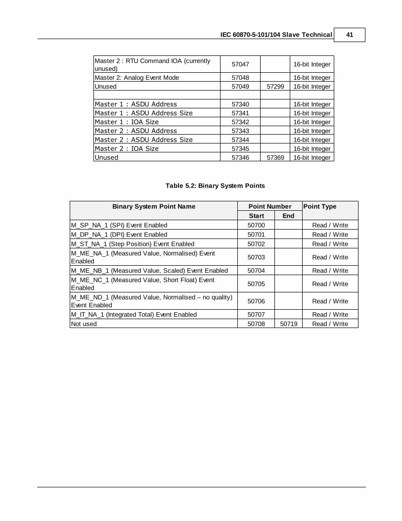
Master 2 : RTU Command IOA (currentlyunused)
57047 16-bit Integer
Master 2: Analog Event Mode 57048 16-bit Integer
Unused 57049 57299 16-bit Integer
Master 1 : ASDU Address 57340 16-bit Integer
Master 1 : ASDU Address Size 57341 16-bit Integer
Master 1 : IOA Size 57342 16-bit Integer
Master 2 : ASDU Address 57343 16-bit Integer
Master 2 : ASDU Address Size 57344 16-bit Integer
Master 2 : IOA Size 57345 16-bit Integer
Unused 57346 57369 16-bit Integer
Table 5.2: Binary System Points
Binary System Point Name Point Number Point Type
Start End
M_SP_NA_1 (SPI) Event Enabled 50700 Read / Write
M_DP_NA_1 (DPI) Event Enabled 50701 Read / Write
M_ST_NA_1 (Step Position) Event Enabled 50702 Read / Write
M_ME_NA_1 (Measured Value, Normalised) EventEnabled
50703 Read / Write
M_ME_NB_1 (Measured Value, Scaled) Event Enabled 50704 Read / Write
M_ME_NC_1 (Measured Value, Short Float) EventEnabled
50705 Read / Write
M_ME_ND_1 (Measured Value, Normalised – no quality)Event Enabled
50706 Read / Write
M_IT_NA_1 (Integrated Total) Event Enabled 50707 Read / Write
Not used 50708 50719 Read / Write
SCADAPack E IEC 60870-5-101/104 Slave Technical Manual42
6.7 Applying Configurations & Configuration Diagnostics
Applying ConfigurationsEvery required configuration may be included in a single configuration file.
These configurations may be generated OFFLINE, and then applied to the RTU as required using the Write RTU Configuration facility in the SCADAPack E Configurator. The RTU configuration proceduresare detailed in the SCADAPack E Configuration Technical Reference Manual.
The serial port configurations required to activate the IEC 60870-5-101 Slave driver are detailed inSection Serial Port Configurations. The RTU needs to be restarted after applying changed serial portconfigurations for them to take effect.
The IEC 60870-5-101/104 System configurations detailed in IEC 60870-5-101 System Configurationsrequire a restart of the RTU’s IEC 60870-5-101/104 driver for these configurations to take effect.
SCADAPack E Configurator will restart the IEC 60870-5-101/104 driver where required to haveconfiguration changes take effect. Consult the SCADAPack E Operational Reference Manual for othermethods to restart various SCADAPack E drivers.
Individual point configurations also require a restart of the RTU’s 60870-5-101/104 driver for thesechanged configurations to take effect.
See Point Configuration.
If these individual point configurations have been applied using the SCADAPack E Configurator RecordExchange write or Point Attributes dialog write, a 30 second timer is started. If any subsequentRecord Exchange writes with modified IEC 60870-5 configurations are received by the RTU within that30 seconds, this timer is restarted. Once the timer expires, the 60870-5-101/104 driver is automaticallyrestarted by the RTU.
Configuration DiagnosticsIEC 60870-5-101/104 configuration diagnostics are generated whenever the IEC 60870-5-101/104 driver isrestarted. On detection of a configuration mismatch, the status code system point (analog 50020) iswritten with the value 3004.
Consult the SCADAPack E Operational Reference Manual for detailed descriptions of RTU statuscodes.
The following conditions may cause a 60870-5-101/104 configuration diagnostics:
IEC 60870-5-101/104 system configurations invalid
invalid double point configuration, e.g. second point doesn’t exist OR second point has a non-zeroInformation Object Address (IOA)
duplicate Information Object Address (IOA) detected
invalid ASDU type for specified point type
insufficient memory on driver start-up
IEC 60870-5-101/104 Slave Technical 43
6.8 Compatibility between SCADAPack E or SCADAPack E Configurator versions7.84 (and newer) and previous versions.
In previous versions, 7.83 or earlier, the ASDU Size and ASDU Address Size and the IOA Size did notuse sperate system points.These parameters were set to default values and were not configurable. WithSCADAPack E firmware version 7.84 and SCADAPack E Configurator version 7.84 the ASDU size andaddress size and the IOA size have individual system points and are user configurable. When upgradingto SCADAPack E or SCADAPack E Configurator versions 7.84 and newer some important compatibilityquestions need to be considered.
Using new SCADAPack E Configurator (Version 7.84 and newer) to Read From OlderSCADAPack E (Version 7.83 and older) Firmware
Older versions of firmware do not have the new system points defined for ASDU and IOA parameters.SCADAPack E Configurator version 7.84 and newer updates the SCADAPack E Configurator displayvalues and the configuration file based on the system point values it reads from the older firmware. Theresult is that any of the new system points for ASDU and IOA will be set to default values.
If the Link + ASDU Address parameter was set to the default value then the value for ASDU addresswill be correct.
If the Link + ASDU Address parameter was not set to the default value then the value for ASDUaddress displayed could be different from the real value in the firmware.
When using SCADAPack E firmware versions 7.83 and older the ASDU addresses parameter must beset to the default value.
Using new SCADAPack E Configurator (Version 7.84 and newer) to Write to Older SCADAPack E(Version 7.83 and older) Firmware
Older versions of firmware do not have the new system points defined for ASDU and IOA parameters.
If the ASDU Address is the same as the Link Address, the ASDU Size is set to the default value andthe IOA Size is set to the default value the configuration will function as expected.
If the conditions listed in the above bullet are not met then the configuration will not function asexpected. The system points used for the new configuration will not be compatible with the systempoints available in the older firmware.
When using SCADAPack E firmware versions 7.83, and older, the ASDU Address Size or the IOA Sizeparameters must be set to the default values. In addition the ASDU Address and the Link Address mustbe the same.
There will be informational messages in the config.log file as the new system points are not defined inthe older firmware.
Older SCADAPack E Configurator (Version 7.83 and older) Reading From new SCADAPack E(Version 7.84 and newer) Firmware
When an older version of SCADAPack E Configurator is used to read from newer firmware, informationfor the new system points will not be available in the SCADAPack E Configurator or in the configurationfile.
If only older versions of SCADAPack E Configurator are used, i.e. no newer versions are used to writeconfigurations, then there are no issues when reading the configuration from the newer firmware. TheASDU Address and Link Address will be the same, the ASDU Address Size will be set to the defaultvalue and the IOA Size will be set to the default values.
When using SCADAPack E Configurator versions 7.83, and older, the ASDU Address Size and the IOASize parameters must be set to the default values. In addition the ASDU Address and the Link Addressmust be the same.
SCADAPack E IEC 60870-5-101/104 Slave Technical Manual44
Older SCADAPack E Configurator (Version 7.83 and older) Writing to New SCADAPack E(Version 7.84 and newer) Firmware
If only older versions of SCADAPack E Configurator are used, i.e. no newer versions are used to writeconfigurations, then there are no issues when writing the configuration to the newer firmware. The ASDUAddress and Link Address will be the same, the ASDU Address Size will be set to the default value andthe IOA Size will be set to the default values.
When using SCADAPack E Configurator versions 7.83, and older, the ASDU Address Size and the IOASize parameters must be set to the default values. In addition the ASDU Address and the Link Addressmust be the same.
7 IEC 60870-5-104 TCP Connections
IEC 60870-5-104 TCP/IP ServiceIn order for IEC 60870-5-104 Master sessions to be initialized, the IEC 60870-5-104 TCP/IP Serviceneeds to be selected.
This service has no impact on -101 sessions. If this service is initialized and the RTU is licensed for IEC60870-5-101/104 then TCP port listeners will be started and 104 channels initialized.
Connecting to -104 Slave SessionsThe section describes how to establish a TCP connection to the -104 slave sessions in the RTU.
A connection to a 104 master session can be established on any Ethernet port or PPP port that hasbeen configured with an IP address.
To establish a connection, a 104 Master needs to attempt a TCP connection to the appropriate IPaddress using TCP port described below.
104 Master session 1 listens on TCP port 2404
104 Master session 2 listens on TCP port 2405
Redundant TCP ConnectionsThe 60870-5-104 driver also supports redundant connections.
The master needs to support redundant connections in order to use redundancy with the RTU. Theconnections to any given Master session form a single Redundancy Group.
Data transfer is valid on only one connection in the redundancy group at a time.
The connection to be used for data transfer is nominated by the Master using the STARTDT commandin the protocol.
It is the Master's role to establish and manage the connections and there is no configuration required forthis in the RTU.
IEC 60870-5-101/104 Slave Technical 45
8 IEC 60870-5 File Transfer
The RTU provide facilities to interface to some of the elements of IEC 60870-5 file transfer.
In particular, IEC transparent data is supported, but without support for directories or other IEC 60870-5file types. For more information see the relevant IEC -101 or -104 interoperability documents.
IEC file transfer of large files can take a long period of time - e.g. inexcess of 15 mins. This timing should be considered with respect to
Master Station communication requirements and timeouts.
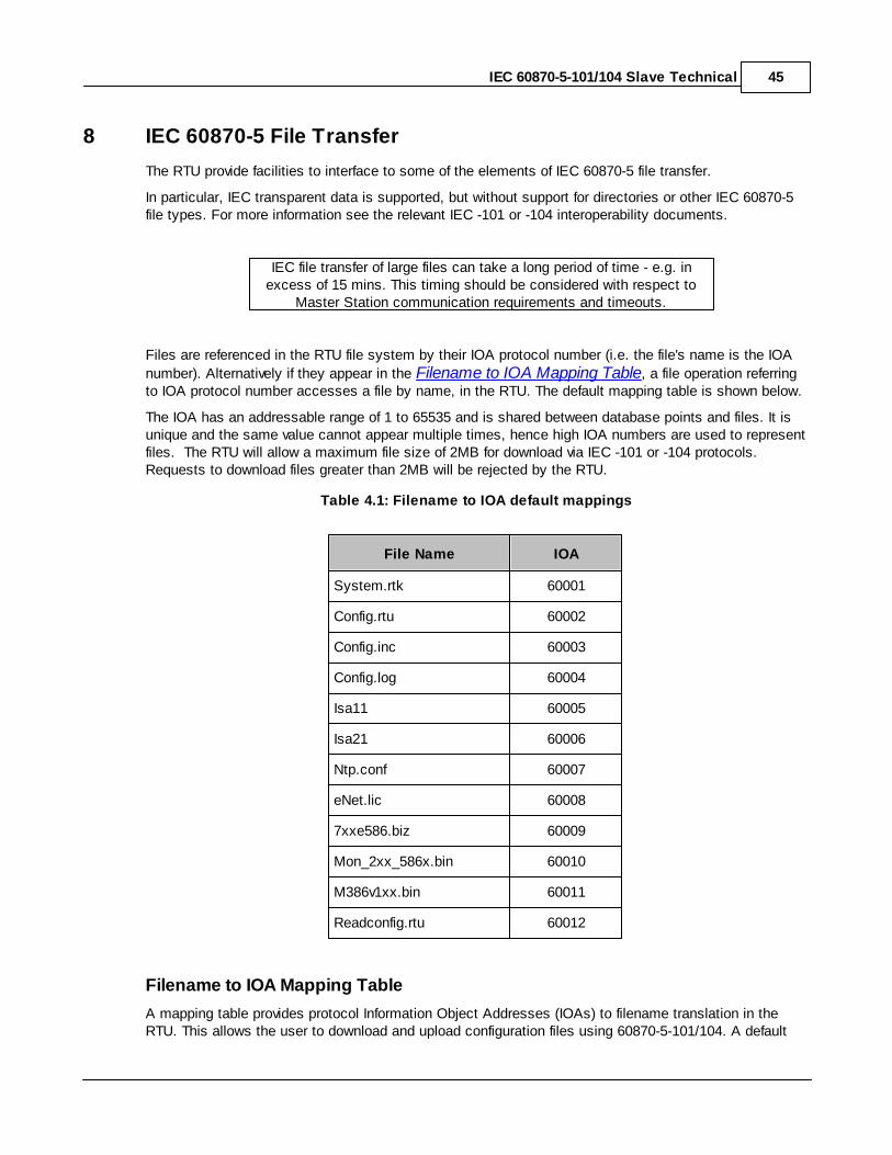
Files are referenced in the RTU file system by their IOA protocol number (i.e. the file's name is the IOA
number). Alternatively if they appear in the Filename to IOA Mapping Table, a file operation referringto IOA protocol number accesses a file by name, in the RTU. The default mapping table is shown below.
The IOA has an addressable range of 1 to 65535 and is shared between database points and files. It isunique and the same value cannot appear multiple times, hence high IOA numbers are used to representfiles. The RTU will allow a maximum file size of 2MB for download via IEC -101 or -104 protocols.Requests to download files greater than 2MB will be rejected by the RTU.
Table 4.1: Filename to IOA default mappings
File Name IOA
System.rtk 60001
Config.rtu 60002
Config.inc 60003
Config.log 60004
Isa11 60005
Isa21 60006
Ntp.conf 60007
eNet.lic 60008
7xxe586.biz 60009
Mon_2xx_586x.bin 60010
M386v1xx.bin 60011
Readconfig.rtu 60012
Filename to IOA Mapping Table
A mapping table provides protocol Information Object Addresses (IOAs) to filename translation in theRTU. This allows the user to download and upload configuration files using 60870-5-101/104. A default

SCADAPack E IEC 60870-5-101/104 Slave Technical Manual46
mapping table is provided in the RTU configuration file. This can be modified manually if required.
Default Filename IOA Mapping table as it appears in text of a *.rtu file
SLT IF #IOA/File Name mapping“System.rtk” 60001“Config.rtu” 60002“Config.inc” 60003“Config.log” 60004“Isa11” 60005“Isa21“ 60006“Ntp.conf” 60007“eNet.lic” 60008“7xxe586.biz” 60009“Mon_2xx_586x.bin” 60010“M386v1xx.bin” 60011“Readconfig.rtu” 60012
IEC 60870-5-101/104 Slave Technical 47
8.1 RTU commands issued via IEC 60870-5
The RTU supports a mechanism for issuing commands via IEC 60870-5-101 and -104 protocol.
An ASDU type 49 Setpoint Command Scaled Value can be sent to an IOA address in the RTU to causea command to be executed. The RTU command IOA system point sets which IOA address is theappropriate address for command (default is IOA 60000).
Different values set in the command IOA address correspond to different commands.
The response to the Setpoint Command is an acknowledgement. This does not indicate that thecommand was successful but rather that it was accepted.
The RTU will not respond to any further IEC 60870-5-101 or -104 messages until after the command hasbeen processed.
The execution of the command will be rapid, though applying particularly large configurations orrestarting the RTU could take a longer period of time.
Also see RTU Command IOA.
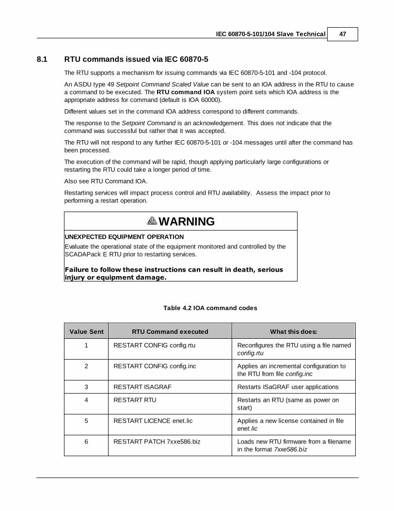
Restarting services will impact process control and RTU availability. Assess the impact prior toperforming a restart operation.
WARNINGUNEXPECTED EQUIPMENT OPERATION
Evaluate the operational state of the equipment monitored and controlled by theSCADAPack E RTU prior to restarting services.
Failure to follow these instructions can result in death, seriousinjury or equipment damage.
Table 4.2 IOA command codes
Value Sent RTU Command executed What this does:
1 RESTART CONFIG config.rtu Reconfigures the RTU using a file named config.rtu
2 RESTART CONFIG config.inc Applies an incremental configuration tothe RTU from file config.inc
3 RESTART ISAGRAF Restarts ISaGRAF user applications
4 RESTART RTU Restarts an RTU (same as power onstart)
5 RESTART LICENCE enet.lic Applies a new license contained in file enet.lic
6 RESTART PATCH 7xxe586.biz Loads new RTU firmware from a filenamein the format 7xxe586.biz
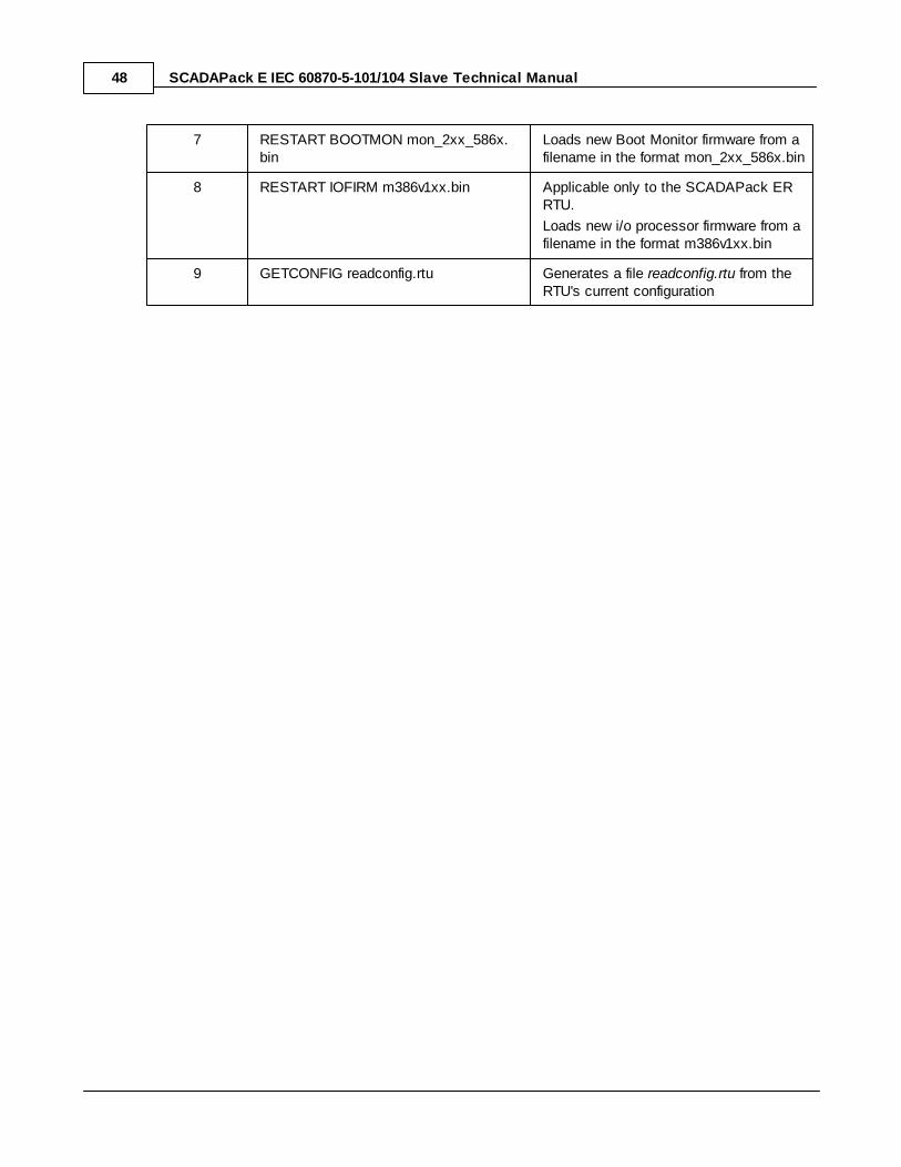
SCADAPack E IEC 60870-5-101/104 Slave Technical Manual48
7 RESTART BOOTMON mon_2xx_586x.bin
Loads new Boot Monitor firmware from afilename in the format mon_2xx_586x.bin
8 RESTART IOFIRM m386v1xx.bin Applicable only to the SCADAPack ERRTU.
Loads new i/o processor firmware from afilename in the format m386v1xx.bin
9 GETCONFIG readconfig.rtu Generates a file readconfig.rtu from theRTU's current configuration
IEC 60870-5-101/104 Slave Technical 49
9 System Information Commands
This section details the additional system commands supported by the RTU’s IEC 60870-5-101/104Slave driver. The RTU will respond to the ASDU types as follows:
Type ID 100: C_IC_NA_1 – Interrogation Command
Type ID 101: C_CI_NA_1 – Counter Interrogation Command
Type ID 103: C_CS_NA_1 – Clock Synchronization Command
Type ID 104: C_TS_NA_1 – Test Command
Type ID 105: C_RP_NA_1 – Reset Process Command
Type ID 107: C_TS_TA_1 – Test Command with Time Tag(104 only)
See the following sections for details of these ASDUs.
ASDU Type ID 100, 101, 103, 104, 105, & 107
SCADAPack E IEC 60870-5-101/104 Slave Technical Manual50
9.1 ASDU Type ID 100, 101, 103, 104, 105, & 107
ASDU Type ID 100 : C_IC_NA_1 - Interrogation CommandThe RTU’s IEC 60870-5-101/104 Slave driver will present Background and Cyclic data as determined bythe system configuration parameters Background Period (for IEC data) and Cyclic Period (for AnalogPoints so configured).
This data may also be reported in response to an Interrogation Command (ASDU Type ID 100). The onlyqualifier supported for the Interrogation Command is the Station Interrogation (20).
The Interrogation Command may be issued by the Master in order to synchronize information betweenthe controlling station (Master) and the controlled station (RTU), or to update the controlling stationdatabase after an initialization procedure has taken place in the RTU.
ASDU Type ID 101 : C_CI_NA_1 - Counter Interrogation CommandThe RTU’s IEC 60870-5-101/104 Slave driver supports Counter Interrogations only in Mode C (Freezeand transmit by counter interrogation commands). The integrated totals (counter points) in the RTU canonly be frozen, reset, or read using the Counter Interrogation Command. The only qualifier supported forthe Counter Interrogation Command is the General Request Counter (5) which references EVERYcounter in the RTU.
Counter values retrieved from the RTU are frozen values. If the Counter Interrogation Command specifiesa FREEZE in the qualifier, the sequence number reported for subsequent READ is incremented. If the Counter Interrogation Command specifies a FREEZE WITH RESET in the qualifier, the Current IntegerValue of the counter configuration point is set to 0, and the Counter Adjusted (CA) bit included in theinformation object is set for the first READ after the FREEZE WITH RESET.
ASDU Type ID 103 : C_CS_NA_1 - Clock Synchronization CommandThe Clock Synchronization Command specifies a CP56Time2a object in the Information Object whichwill used to set the RTU’s real time clock. If the RTU is configured to use NTP time synchronization, the Clock Synchronization Command will NOT set the RTU’s real time clock but will still respond with apositive activation response to the Clock Synchronization Command.
There are multiple methods to time synchronize time in the RTU. If NTP TimeSynchronization is NOT being used, check that ONLY ONE of the slave protocols is beingused for time synchronization, as IEC 60870-5-101 Slave, IEC60870-5-104 Slave and DNP3Slave communications can be used to process time synchronization messages.
ASDU Type ID 104: C_TS_NA_1 - Test CommandThe Test Command is supported by the RTU’s IEC 60870-5-101/104 Slave driver such that specifiedfixed bit pattern is included in the response to the Test Command.
ASDU Type ID 105: C_RP_NA_1 - Reset Process CommandThe Reset Process Command will be processed by the RTU and a positive activation response will beissued. Currently there is no support for restarting any of the RTU’s internal processes. Support for the Reset Process Command will be extended in future firmware releases.
ASDU Type ID 107 : C_TS_TA_1 - Test Command with Time Tag (104 only)

IEC 60870-5-101/104 Slave Technical 51
The Test Command is supported by the RTU’s IEC 60870-5-101/104 Slave driver such that incrementingsequence numbers are included in the response to the Test Command.
SCADAPack E IEC 60870-5-101/104 Slave Technical Manual52
10 Multiple Master Support
The RTU’s IEC 60870-5-101/104 Slave driver will support communications with up to two (2) IEC 60870-5-101 Masters and two (2) IEC 60870-5-104 Masters to a total of 4. The first -101 master and first -104master share common configurations. The second -101 master and second -104 master share commonconfigurations.
When the IEC 60870-5-101/104 facility is licensed on the SCADAPack ERTU, Multiple Master facilities are automatically enabled not requiring an
additional license.
The default configuration enables a single -101 and -104 Master session. The IEC 60870-5-101/104system configurations are duplicated for each enabled Master session. See 60870-5-101 SystemConfigurations. This allows the first and second 101 or 104 Master session to be independentlyconfigured.
Each Master session has its own event list such that a given IEC 60870-5-101/104 event will NOT beremoved from the RTU’s 60870-5-101/104 event list until it has been retrieved by each enabled Mastersession.
The Integrated Totals sequence numbers (see Counter Point ASDU Types) are maintained for eachenabled Master session, i.e. a FREEZE Counter Interrogation Command received from -101 Master 1will only increment the sequence number returned to the next READ request from the -101 Master 1 and-104 Master 1. The sequence number for -101 and -104 Master 2 will remain unmodified.
The two sets of masters must use different serial ports. The second -101 master and second -104master will be disabled if their configuration uses the same serial port as the first -101 master and first -104 master.
11 Command Line Diagnostics
The RTU provides a diagnostic display which can be used to verify IEC 60870-5-101/104communications between the RTU (as a Slave) and the connected Master. These IEC 60870-5diagnostics can be obtained using one of the following methods
direct serial connection to a Cmd Line port
TELNET connection
FILEDIAG (logged diagnostics to RTU File System).
Refer to the SCADAPack E Operational Reference manual for more details on these methods ofaccessing RTU diagnostics.
The S101DIAG command is used to filter IEC 60870-5-101/104 diagnostics displays when in DiagnosticSession display mode (type DIAG at the command line to enter diagnostic mode).
The format of the S101DIAG command is:
S101DIAG mode filter [filter ....]
Where: mode = ENABLE DISABLE
filter = * APPL BYTES LINK TIMESTAMP USER
IEC 60870-5-101/104 Slave Technical 53
For example: S101DIAG ENABLE APPL TIMESTAMP
Enabling IEC 60870-5-101/104 diagnostics can have some impact on system performance. It issuggested that these diagnostics be disabled when not in use.
The command filters can be individually enabled or disabled (these are retained in NV memory).
* All filters enabled / disabled
APPL 60870-5-101/104 Application Layer information
BYTES 60870-5-101/104 Link Layer packet bytes (requires LINK filter)
LINK 60870-5-101/-104 Link Layer packet header information
TIMESTAMP Time of 60870-5-101/104 message diagnostic
USER user application response information
The following sections are examples of filtered diagnostic information where the RTU Link and ASDU(common) address is 21. These examples are time-stamped (i.e. TIMESTAMP filter has been enabled).Outbound link messages are indicated as <---- whereas inbound messages are indicated as ---->.
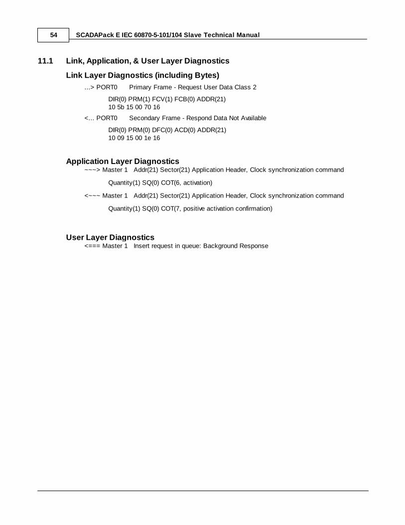
SCADAPack E IEC 60870-5-101/104 Slave Technical Manual54
11.1 Link, Application, & User Layer Diagnostics
Link Layer Diagnostics (including Bytes)
...> PORT0 Primary Frame - Request User Data Class 2
DIR(0) PRM(1) FCV(1) FCB(0) ADDR(21)10 5b 15 00 70 16
<... PORT0 Secondary Frame - Respond Data Not Available
DIR(0) PRM(0) DFC(0) ACD(0) ADDR(21)10 09 15 00 1e 16
Application Layer Diagnostics~~~> Master 1 Addr(21) Sector(21) Application Header, Clock synchronization command
Quantity(1) SQ(0) COT(6, activation)
<~~~ Master 1 Addr(21) Sector(21) Application Header, Clock synchronization command
Quantity(1) SQ(0) COT(7, positive activation confirmation)
User Layer Diagnostics<=== Master 1 Insert request in queue: Background Response

IEC 60870-5-101/104 Slave Technical 55