Embed Size (px)
Citation preview

SCADAPack 32
IEC 61131-3 Quick Start Guide
2/18/2016

2/18/2016
Copyright © 2014 - 2016 Schneider Electric Canada Inc.
All rights reserved.
The information provided in this documentation contains general descriptions and/or technical characteristics of the performance of the products contained herein. This documentation is not intended as a substitute for and is not to be used for determining suitability or reliability of these products for specific user applications. It is the duty of any such user or integrator to perform the appropriate and complete risk analysis, evaluation and testing of the products with respect to the relevant specific application or use thereof. Neither Schneider Electric nor any of its affiliates or subsidiaries shall be responsible or liable for misuse of the information contained herein. If you have any suggestions for improvements or amendments or have found errors in this publication, please notify us.
No part of this document may be reproduced in any form or by any means, electronic or mechanical, including photocopying, without express written permission of Schneider Electric.
All pertinent state, regional, and local safety regulations must be observed when installing and using this product. For reasons of safety and to help ensure compliance with documented system data, only the manufacturer should perform repairs to components.
Trademarks
Schneider Electric, ClearSCADA, SCADAPack, Solarpack, Realflo, Telepace, Telebus, SCADAServer, and Modbus are trademarks and the property of Schneider Electric SE, its subsidiaries and affiliated companies. All other trademarks are the property of their respective owners.
Microsoft and Windows are registered trademarks or trademarks of Microsoft Corporation in the United States and/or other countries.
Address
Schneider Electric Telemetry & Remote SCADA Solutions 415 Legget Drive, Suite 101, Kanata, Ontario K2K 3R1 Canada Direct Worldwide: +1 (613) 591-1943 Fax: +1 (613) 591-1022 Toll Free within North America: 1 (888) 267-2232 www.schneider-electric.com

SCADAPack 32 IEC 61131-3 Quick Start Guide
Document (Version 2.26.1.179) 2/18/2016 2 2
Table of Contents
Technical Support..........................................................................3
Technical Support: Americas, Europe, Middle East, Asia ..................................... 3 Technical Support: Australia .................................................................................. 3
Safety Information .........................................................................4
Important Information ............................................................................................. 4 Please Note ............................................................................................................ 5 Before You Begin ................................................................................................... 5 Operation and Adjustments ................................................................................... 5 Acceptable Use ...................................................................................................... 6
About The Book .............................................................................7
At a Glance ............................................................................................................ 7
Overview .........................................................................................8
Quick-Start Procedure ...................................................................9
Prepare the SCADAPack 32 .................................................................................. 9 Install IEC 61131-3 Software ............................................................................... 11 Start IEC 61131-3 ................................................................................................ 12 Create an IEC 61131-3 Project ............................................................................ 13 Select the Controller Type for the Project ............................................................ 14 Configure Serial Connection to SCADAPack 32 ................................................. 15 Confirm Serial Connection to SCADAPack 32 .................................................... 17 Declare Variables ................................................................................................. 18 Select I/O Hardware ............................................................................................. 19 Select Functions and Function Blocks ................................................................. 19 Controller Commands and Options ...................................................................... 19 Make the Application ............................................................................................ 20 Write and Start the Application ............................................................................ 20

SCADAPack 32 IEC 61131-3 Quick Start Guide
Document (Version 2.26.1.179) 2/18/2016 3 3
Technical Support
Questions and requests related to any part of this documentation can be directed to one of the following support centers:
Technical Support: Americas, Europe, Middle East, Asia
Available Monday to Friday 8:00am – 6:30pm Eastern Time
Toll free within North America 1-888-226-6876
Direct Worldwide +1-613-591-1943
Email [email protected]
Technical Support: Australia
Inside Australia 1300 369 233
Email [email protected]

SCADAPack 32 IEC 61131-3 Quick Start Guide
Document (Version 2.26.1.179) 2/18/2016 4 4
Safety Information
Important Information
Read these instructions carefully and look at the equipment to become familiar with the device before trying to install, operate, service, or maintain it. The following special messages may appear throughout this documentation or on the equipment to warn of potential hazards or to call attention to information that clarifies or simplifies a procedure.
The addition of this symbol to a Danger or Warning safety message indicates that an electrical hazard exists, which will result in personal injury if the instructions are not followed.
This is the safety alert symbol. It is used to alert you to potential personal injury hazards. Obey all safety messages that follow this symbol to avoid possible injury or death.
DANGER DANGER indicates a hazardous situation which, if not avoided, will result in death or serious injury.
WARNING WARNING indicates a hazardous situation which, if not avoided, can result in death or serious injury.
CAUTION CAUTION indicates a potentially hazardous situation which, if not avoided, can result in minor or moderate injury.
NOTICE NOTICE is used to address practices not related to physical injury.

SCADAPack 32 IEC 61131-3 Quick Start Guide
Document (Version 2.26.1.179) 2/18/2016 5 5
Please Note
Electrical equipment should be installed, operated, serviced, and maintained only by qualified personnel. No responsibility is assumed by Schneider Electric for any consequences arising out of the use of this material.
A qualified person is one who has skills and knowledge related to the construction and operation of electrical equipment and the installation, and has received safety training to recognize and avoid the hazards involved.
Before You Begin
Do not use this product on machinery lacking effective point-of-operation guarding. Lack of effective point-of-operation guarding on a machine can result in serious injury to the operator of that machine.
WARNING
EQUIPMENT OPERATION HAZARD
Verify that all installation and set up procedures have been completed.
Before operational tests are performed, remove all blocks or other temporary holding means used for shipment from all component devices.
Remove tools, meters, and debris from equipment.
Failure to follow these instructions can result in death or serious injury.
Follow all start-up tests recommended in the equipment documentation. Store all equipment documentation for future reference.
Test all software in both simulated and real environments.
Verify that the completed system is free from all short circuits and grounds, except those grounds installed according to local regulations (according to the National Electrical Code in the U.S.A, for instance). If high-potential voltage testing is necessary, follow recommendations in equipment documentation to prevent accidental equipment damage.
Operation and Adjustments
The following precautions are from the NEMA Standards Publication ICS 7.1-1995 (English version prevails):
Regardless of the care exercised in the design and manufacture of equipment or in the selection and ratings of components, there are hazards that can be encountered if such equipment is improperly operated.
It is sometimes possible to misadjust the equipment and thus produce unsatisfactory or unsafe operation. Always use the manufacturer’s instructions as a guide for functional adjustments. Personnel who have access to these adjustments should be familiar with the equipment

SCADAPack 32 IEC 61131-3 Quick Start Guide
Document (Version 2.26.1.179) 2/18/2016 6 6
manufacturer’s instructions and the machinery used with the electrical equipment.
Only those operational adjustments actually required by the operator should be accessible to the operator. Access to other controls should be restricted to prevent unauthorized changes in operating characteristics.
Acceptable Use
SCADAPack controllers and expansion modules are intended for use in monitoring and controlling non-critical equipment only. They are not intended for safety-critical applications.
WARNING
UNACCEPTABLE USE
Do not use SCADAPack controllers and expansion modules as an integral part of a safety system. These devices are not safety products.
Failure to follow these instructions can result in death or serious injury.
CAUTION
EQUIPMENT OPERATION HAZARD
When devices are used for applications with technical safety requirements, the relevant instructions must be followed.
Use only Schneider Electric software or approved software with Schneider Electric hardware products.
Failure to follow these instructions can result in minor or moderate injury.
SCADAPack 32 Controller
Document (Version 2.26.1.179) 2/18/2016 7 7
About The Book
At a Glance
Document Scope
This manual describes getting started with the SCADAPack 32 controller using IEC 61131-3 programming.
Validity Notes
This document is valid for all versions of the SCADAPack 32 controller.
Product Related Information
WARNING UNINTENDED EQUIPMENT OPERATION
The application of this product requires expertise in the design and programming of control systems. Only persons with such expertise should be allowed to program, install, alter and apply this product.
Follow all local and national safety codes and standards.
Failure to follow these instructions can result in death or serious injury.
User Comments
We welcome your comments about this document. You can reach us by e-mail at [email protected].
SCADAPack 32 Controller
Document (Version 2.26.1.179) 2/18/2016 8 8
Overview
This document is meant to be a guide to help new users configure, program and operate the SCADAPack 32 controller in a timely fashion. It is not meant as a substitute for the IEC61131 and SCADAPack 32 Controller manuals, but rather as a companion to these manuals. A strong background in both programmable logic controllers (PLC) and personal computers (PC) using Windows is highly recommended. If you experience any difficulty during the setup, it may be necessary to then consult the appropriate manual or call Schneider Electric Technical Support for assistance.
SCADAPack 32 Controller
Document (Version 2.26.1.179) 2/18/2016 9 9
Quick-Start Procedure
This section of the manual is a starting point in the development of an IEC 61131-3 application for a SCADAPack 32 controller. Each of the steps listed below is fully described in the following sections. This manual and the IEC 61131-3 User’s Guide should be used together to provide the information needed to create, load and run an application.
Prepare the SCADAPack 32.
Install IEC 61131-3.
Create an IEC 61131-3 project.
Declare variables.
Select I/O hardware.
Select custom functions and function blocks.
Configure PC to controller Link.
Configure controller commands and options.
Make the application.
Write the application to the controller and start the application.
Prepare the SCADAPack 32
In this step the SCADAPack 32 controller is prepared for connection to a PC that will be running IEC 61131-3. Referring to the graphic and directions below we will:
Connect a power suitable power source.
Clear any existing programs in the SCADAPack 32 and set the communication parameters to a default value.
Connect a serial cable between the SCADAPack 32 and the PC.

SCADAPack 32 Controller
Document (Version 2.26.1.179) 2/18/2016 10 10
Connect Power
The SCADAPack 32 requires an 11 to 24Vdc power source. Connect this source to the DC PWR terminals on both the SCADAPack controller and the I/O board and check for proper polarity. The power source remains turned off at this time.
Cold Boot the SCADAPack 32 Controller
A Cold Boot of the SCADAPack 32 erases any programs and sets the serial communication parameters to default values. The default parameters are Modbus RTU, 9600 baud, no parity and 1 stop bit.

SCADAPack 32 Controller
Document (Version 2.26.1.179) 2/18/2016 11 11
WARNING
UNEXPECTED EQUIPMENT OPERATION
Evaluate the operational state of the equipment being monitored or controlled by the controller before removing power.
Failure to follow these instructions can result in death or serious injury.
NOTICE DATA LOSS
Starting the controller in Cold Boot mode returns controller configuration parameters to their default settings and erases applications created in SCADAPack Workbench and ISaGRAF 3 Workbench. This information must be reloaded into the controller for correct controller operation.
Before starting the controller in Cold Boot mode, save a copy of the controller configuration information, user-created applications, logs and other data to an external drive so it can be reloaded when the procedure is complete.
Failure to follow these instructions can result in loss of files related to configuration and data collection.
To perform a Cold Boot:
1. Press and hold down the LED POWER button.
2. Turn ON the 11 to 24Vdc power source..
3. Continue holding the LED POWER button for 25 seconds until the STAT Led begins to flash on and off continuously.
4. Release the LED POWER button.
5. Reload the controller configuration and user-created applications from backup.
Connect serial cable between SCADAPack 32 and PC.
Connect a null modem cable from a PC serial port to COM2 on the SCADAPack 32. This cable is used to connect from an RJ-45 based RS-232 port on the SCADAPack 32 controller to DE-9P connector on a DTE such as a PC. A 10 ft. long cable is available from Schneider Electric s as part number TBUM297217.
Install IEC 61131-3 Software
Insert the IEC 61131-3 CD into the CD ROM drive. The CD will autorun and start the installation wizard. Follow the installation wizard instructions to install the IEC 61131-3 programming software.

SCADAPack 32 Controller
Document (Version 2.26.1.179) 2/18/2016 12 12
When first installed IEC 61131-3 will run in the Demo Mode until a permanent license is installed. The Demo version will run for a maximum of 30 days. This Quick Start Guide can be used in the IEC 61131-3 Demo Mode. Refer to the IEC61131 User and Reference manual for further information on installing the license for IEC 61131-3.
The following message is displayed when Projects is selected from the IEC 61131-3 3.5 program group.
When running in the Demo Mode IEC 61131-3 does not support the following features:
Archiving or Restoring projects.
Exporting IEC 61131 programs to a library.
Exporting variables.
Embedding project source code in a target controller.
Uploading source code from a target controller.
You will need to permanently license your copy of IEC 61131-3 version 3.5 in order to use the above listed features.
Start IEC 61131-3
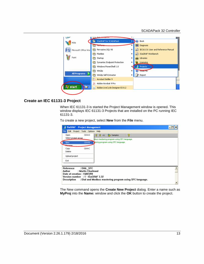
Start IEC 61131-3 by selecting IEC 61131-3 for SCADAPack from the Windows Start menu. From the list of items select Projects to open IEC 61131-3. The IEC61131 User and Reference Manual can be selected from the menu items.
SCADAPack 32 Controller
Document (Version 2.26.1.179) 2/18/2016 13 13
Create an IEC 61131-3 Project
When IEC 61131-3 is started the Project Management window is opened. This window displays IEC 61131-3 Projects that are installed on the PC running IEC 61131-3.
To create a new project, select New from the File menu.
The New command opens the Create New Project dialog. Enter a name such as MyProj into the Name: window and click the OK button to create the project.

SCADAPack 32 Controller
Document (Version 2.26.1.179) 2/18/2016 14 14
Select the Controller Type for the Project
Projects in IEC 61131-3 are created for a specific controller type. To select the SCADAPack 32 controller open the Controller commands from the Tools menu and select Controller Type from the Controller commands.

SCADAPack 32 Controller
Document (Version 2.26.1.179) 2/18/2016 15 15
When the Controller Type command is selected the Select Controller Type dialog is opened. Use the menu selector at the right of the window to select SCADAPack 32 and then click the Select button.
Configure Serial Connection to SCADAPack 32
A communication link is used to connect IEC 61131-3 and the target SCADAPack 32 controller. IEC 61131-3 controls the downloading of applications to the target controller, monitoring the applications running in the target controller and the starting and stopping of applications in the target controller.
The IEC 61131-3 PC-PLC Link parameters define how the communication link between the PC and the target controller functions. To open the PC_PLC link parameters dialog:
Select Link setup from the Debug menu.
When selected the PC-PLC Link Parameters dialog is displayed.
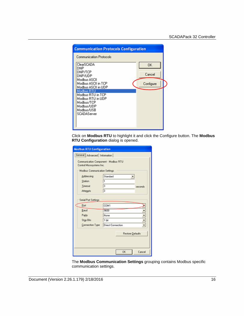
Click the Setup button to open the Communication Protocols Configuration dialog and set the communication parameters.
SCADAPack 32 Controller
Document (Version 2.26.1.179) 2/18/2016 16 16
Click on Modbus RTU to highlight it and click the Configure button. The Modbus RTU Configuration dialog is opened.
The Modbus Communication Settings grouping contains Modbus specific communication settings.

SCADAPack 32 Controller
Document (Version 2.26.1.179) 2/18/2016 17 17
Set the Addressing parameter to Standard.
Set the Station parameter to 1.
Set the Timeout parameter to 3.
Set the Attempts parameter to 3.
This Serial Port Settings grouping contains details directly related to the PC’s communication port including the port number, the baud rate, parity and stop bit settings.
Set the Port parameter for the PC serial port to use. The drop-down list will display available serial ports on the PC. The available serial ports list will include any USB to serial converters used on the PC.
Set the Baud parameter to 9600.
Set the Parity parameter to none.
Set the Stop Bits parameter to 1.
Set the Connection Type parameter to Direct Connection.
Confirm Serial Connection to SCADAPack 32
To confirm that the PC is able to communicate with the SCADAPack 32 controller a check of the Real Time Clock can be made. To select the Real Time Clock command open the Controller commands from the Tools menu and select Real Time Clock from the Controller commands list.
SCADAPack 32 Controller
Document (Version 2.26.1.179) 2/18/2016 18 18
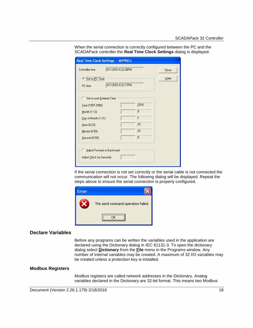
When the serial connection is correctly configured between the PC and the SCADAPack controller the Real Time Clock Settings dialog is displayed.
If the serial connection is not set correctly or the serial cable is not connected the communication will not occur. The following dialog will be displayed. Repeat the steps above to ensure the serial connection is properly configured.
Declare Variables
Before any programs can be written the variables used in the application are declared using the Dictionary dialog in IEC 61131-3. To open the dictionary dialog select Dictionary from the File menu in the Programs window. Any number of internal variables may be created. A maximum of 32 I/O variables may be created unless a protection key is installed.
Modbus Registers
Modbus registers are called network addresses in the Dictionary. Analog variables declared in the Dictionary are 32-bit format. This means two Modbus

SCADAPack 32 Controller
Document (Version 2.26.1.179) 2/18/2016 19 19
registers will be automatically assigned to an analog variable within the controller. Refer to the Modbus Addressing section of the IEC 61131-3 User and Reference manual for complete information on how Modbus registers are used in IEC 61131-3 applications.
The dictionary dialog will use hexadecimal format for the network address when the dialog is first opened. To change the format to decimal:
Select Advanced options from the Tools menu in the Programs window.
Click the Network addresses in decimal option.
Input / Output Variables
Variables with the attribute input or output are assigned to I/O Boards or I/O Equipment in the I/O Connection dialog. Only variables of these types may be assigned to physical hardware input or output devices.
Select I/O Hardware
The term I/O hardware refers to the physical input and output devices that are accessed by the application program in the target controller. The I/O hardware is divided into two types, I/O boards and I/O equipment. I/O boards are 5000 I/O modules and controller onboard I/O such as counter/digital inputs, interrupt input, RAM battery voltage and board temperature. I/O equipment are I/O modules that contain multiple types of I/O such the SCADAPack 32 lower I/O modules.
I/O boards and equipment are defined using the I/O connection dialog in IEC 61131-3. To open the I/O connection dialog select I/O connection from the Project menu in the Programs window.
Select Functions and Function Blocks
Functions and function blocks are used in programs written in any of the IEC11 31-3 languages. Descriptions and examples of IEC 61131-3 functions and function blocks are found in section B.9 Standard operators, function blocks and functions of the IEC 61131-3 User’s Guide.
Schneider Electric custom functions and function blocks have been added to the standard IEC 61131-3 environment. These functions support features provided by the SCADAPack controllers.
Controller Commands and Options
Controller commands are specific to the operation of SCADAPack controllers. Operating parameters are configured using selected controller commands. Controller commands are selected from the Controllers selection in the Tools menu of the Programs window.
Controller parameters such as serial port settings, initialization, I/O indication and controller locking functions are configured using controller commands. Control of the connection and disconnection of dialup modem communication links and reading and writing parameters to the controller are also executed using controller commands.

SCADAPack 32 Controller
Document (Version 2.26.1.179) 2/18/2016 20 20
Make the Application
An application is compiled before it is written to the target controller it must be compiled. Compiling an IEC 61131-3 project is done using the Make Application command.
To make an application:
Select Compiler Options from the Make menu in the Programs window. The Compiler Options dialog appears.
In the Targets: list, select ISA86M: TIC code for Intel. This is the target Independent Code dedicated to IEC 61131-3 kernels installed on Intel based processors.
Select the appropriate compiler options for you project by clicking the square to the right of the option in the Optimizer: section of the dialog.
If you wish to be able to read the project from a controller select the Upload button and then, in the Prepare project for upload dialog click the Embed source code for upload option. Select the parameters you wish to upload in the Embed also: window. Click the OK button to close the dialog.
Click on the Select button to select the target and then click the OK button to close the dialog.
Select Make application from the Make menu in the Programs window.
The Code Generator window opens and a listing of the compiler output messages are displayed as the application is made.
If the compiler does not make the application it will display a list indicating reasons. Once corrections have been completed and the application has been successfully made it is ready for writing to the target controller.
Write and Start the Application
Application writing and execution control is accomplished using the IEC 61131-3 debugger. Refer to section A.15 Using the graphic debugger of the IEC 61131-3 User’s Guide for complete information on the debugger.
To write an application to the target controller:
Select Debug from the Debug menu in the Programs window.
The debugger automatically connects to the target controller using the communication link. The Debugger window is opened.
Select Download from the File menu in the Debugger window.
Select ISA86M: TIC code for Intel from the Download dialog.
A progress bar will display the progress of the download command.
Once the download is complete the application will start to run.
The application may now be viewed in real time. Select the Dictionary or one of the programs in the Programs window to view real time data.

SCADAPack 32 Controller
Document (Version 2.26.1.179) 2/18/2016 21 21
The Quick-Start procedure is complete!