Embed Size (px)
Citation preview

SBR and DBRSpacer Bracers
(800) 999-5099strongtie.com
The New Tested Solution for Faster Stud Layout
Distributed by:
For more information, please contact Marino\WARE at 800.627.4661 or visit www.MarinoWARE.comCAT_SBR_REV_1_01162017
2
© 2
017
Sim
pson
Str
ong-
Tie
Com
pany
Inc.
F-C
F-S
BR
DB
R17
16"
12"
24"
16"
12"
1⅜"
24"
50¾"
½"
½"
0.17" dia.(typ.)
5⁄16"
2¼"
SBR/43 Dimensions and Section Profile
Simpson Strong-Tie introduces the SBR and DBR spacer bracers for cold-formed steel construction. These spacer bracers reduce the installed cost of cold-formed steel stud walls by enabling faster stud layout while minimizing the need for bridging clips.
The DBR is used for interior walls to eliminate stud bow and allow for quicker drywall attachment, while the SBR is designed for structural exterior walls. Both products provide bracing along the length of the stud, and for head-of-wall slip conditions. The SBR and DBR also come with prepunched slots that eliminate the need to use bridging clips with on-module studs.
The SBR and DBR spacer bracers come with bracing load data based on assembly testing, thus mitigating risk for designers and maximizing confidence in design specs. In fact, the SBR and DBR are the only spacer bracers on the market with tabulated design values based on assembly tests.
SBR and DBR Spacer Bracers
SBR/43 Typical Installation
Spacing slots12", 16" and 24" o.c.
Prepunched holes for screw installation
when splicing is needed
Pilot hole (screws not required)
SBR and DBR spacer bracers are conveniently packaged in durable 20-piece boxes to simplify ordering and storage.
SBR/43Structural Spacer Bracer
Patent Pending
3
© 2
017
Sim
pson
Str
ong-
Tie
Com
pany
Inc.
F-C
F-S
BR
DB
R17
Features:
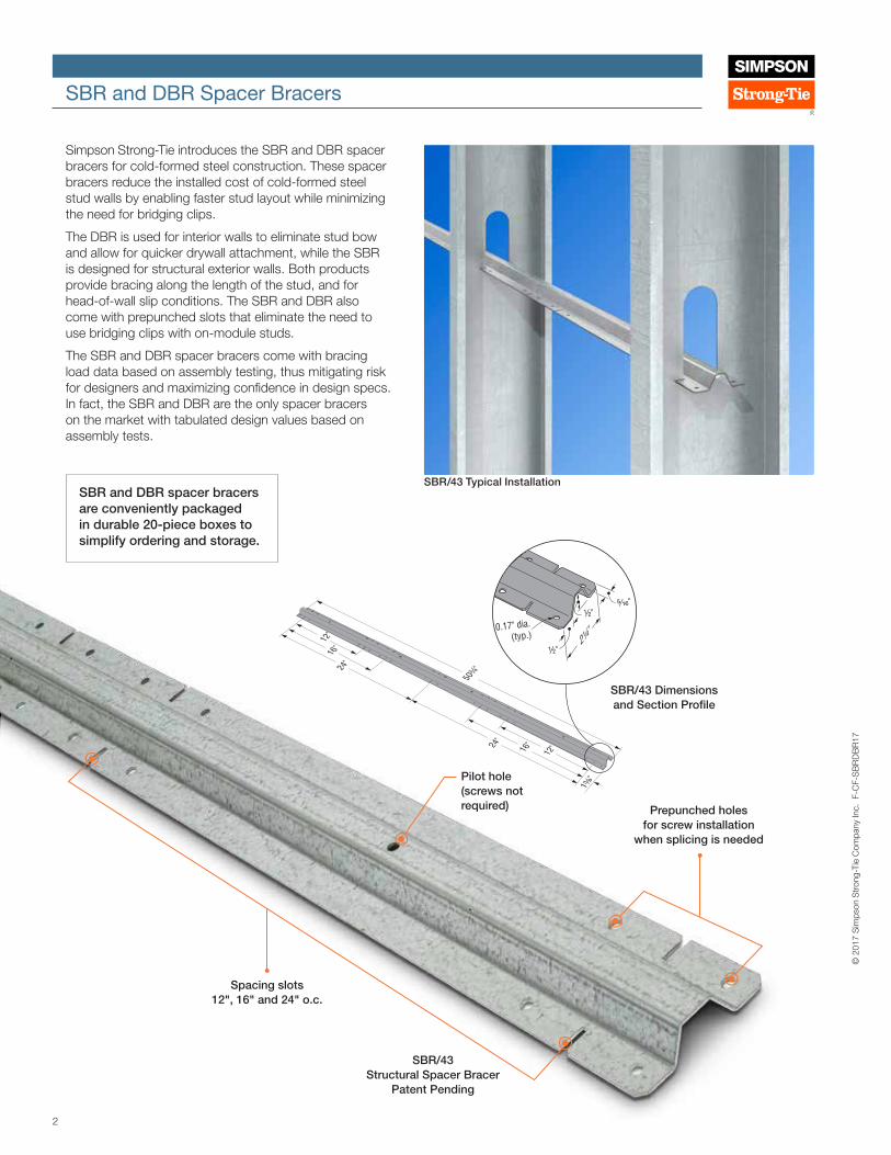
• SBR and DBR have patent-pending precision-engineered prepunched slots strategically located to enable 12", 16" and 24" on-center stud spacing and can be used to space the studs without having to mark the top track for layout.
• The SBR will accommodate 3 5/8" and 6" studs in thicknesses of 33 mil (20 ga.) thru 68 mil (14 ga.).
• The DBR will accommodate 2 1/2", 3 5/8" and 6" studs in thicknesses of 15 mil (25 ga. EQ) through 33 mil (20 ga.).
• Prepunched holes in the SBR provide rapid screw installation when spacer-bracer splices are needed for axial load-bearing studs.
• In off-layout or end-of run conditions, the hat-section profiles enable clip attachments to the stud with Simpson Strong-Tie® LSSC or RCA connectors.
Installation:
• Spacer-bracers are fed through the stud knockout at a 90-degree angle until studs align with spacer-bracer slots. With the slots engaging the stud web, the spacer-bracer is then rotated back to the flat position so that the slotted flanges are on the bottom.
• For off-layout or end-of-run studs where a spacer-bracer slot does not engage a stud, manually snip the spacer-bracer flanges with a ½" deep slot and secure the spacer bracer to the stud with Simpson Strong-Tie LSSC or RCA connectors. Use all specified fasteners.
• Wear gloves while handling and installing spacer bracers.
SBR and DBR Spacer Bracers
DBR/30 Typical Installation
Spacing slots12", 16" and 24" o.c.
Material: SBR/43 — 43 mil (40 ksi); DBR/30 — 27 mil (33 ksi)
Finish: Galvanized (G90)
Codes: Testing performed in accordance with ICC-ES AC261. Visit stongtie.com for the latest load values and testing
Ordering Information:
SBR/43-R20 (Box of 20)DBR/30-R20 (Box of 20)
16"
12"
24"
16"
12"
1⅜"
24"
50¾"
½"
¼" ¼"
1⅝"
16"12"
24"
16"12"
1⅜"
24"
50¾"
½"
¼" ¼"
1⅝"
DBR/30 Dimensions and Section Profile
© 2
017
Sim
pson
Str
ong-
Tie
Com
pany
Inc.
F-C
F-S
BR
DB
R17
Pilot hole (screws not required)
DBR/30Drywall Spacer Bracer
Patent Pending
4
© 2
017
Sim
pson
Str
ong-
Tie
Com
pany
Inc.
F-C
F-S
BR
DB
R17
SBR and DBR Spacer Bracers
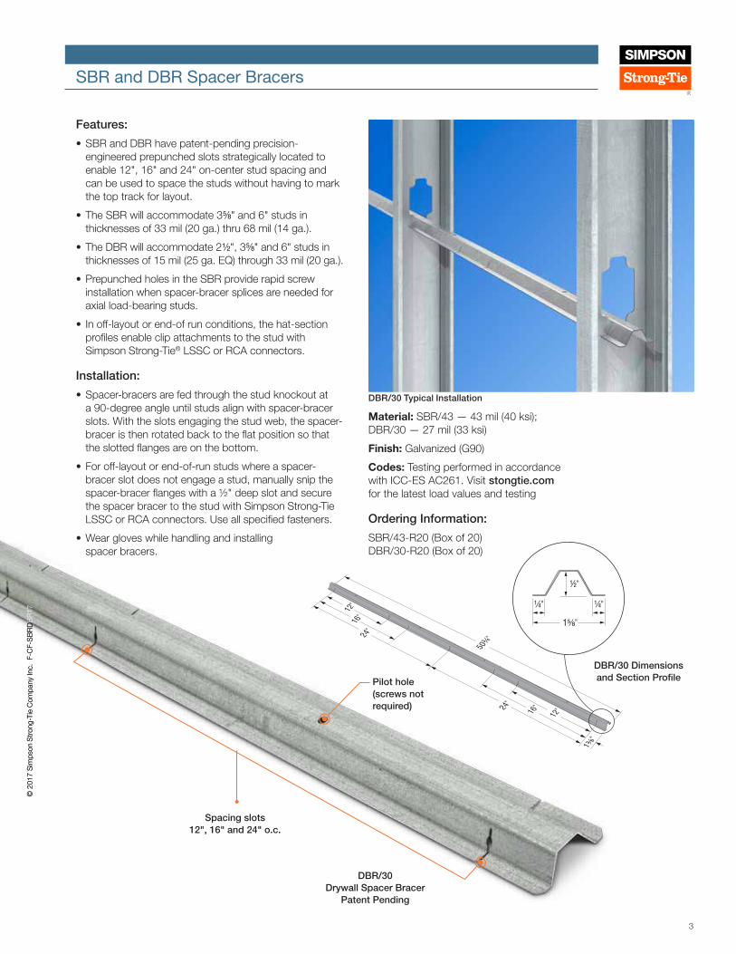
SBR and DBR Spacer Bracer — Connection Strength and Stiffness
Model No.
Stud Depth (in.)
Stud Thickness mil (ga.)
Allowable Torsional Moment (in./lb.)
Allowable Brace
Strength (lb.)
Brace Stiffness (lb./in.)
SBR/43
3 5/8
33 (20) 235 390 845
43 (18) 310 435 1,390
54 (16) 400 435 1,390
68 (14) 400 435 1,390
6
33 (20) 215 160 495
43 (18) 310 330 765
54 (16) 365 450 840
68 (14) 365 450 840
DBR/30
3 5/8
15 (25 EQ) 55 — —
18 (25) 55 — —
19 (20 EQ) 60 — —
30 (20 DW) 85 — —
33 (20 STR) 90 — —
6
15 (25 EQ) 55 — —
18 (25) 55 — —
19 (20 EQ) 60 — —
30 (20 DW) 85 — —
33 (20 STR) 90 — —
SBR Axially Loads
Axial load
Brace strength
Brace stiffness
SBR Laterally Loads
Lateral load
Bracingforce-couple
Bracing
force-couple
Stud depth
Torsional
moment
Axially Loaded C-Stud with SBR Spacer Bracer
Laterally Loaded C-Stud with SBR Spacer Bracer
(DBR Spacer Bracer Similar)
SBR and DBR Gross PropertiesModel
No.
Design Thickness
(in.)Fy (ksi) Area
(in.2) Ix (in.4) Sx (in.3) Rx (in.) Iy (in.4) Sy (in.3) Ry (in.)Torsional Properties
Jx1,000 (in.4) Cw (in.6) Yo (in.) m (in.) Ro (in.) β
SBR/43 0.0468 40 0.126 0.0047 0.1458 0.1936 0.0436 0.0400 0.5891 0.0916 5.56E-04 0.283 -0.017 0.681 0.828
DBR/30 0.0289 33 0.060 0.0023 0.0082 0.1936 0.0109 0.0141 0.4259 0.0167 7.05E-05 0.346 0.087 0.582 0.647
SBR and DBR Allowable Member Strengths Model
No.Ma (Fy) (in.-lb.)
Ma (12" o.c.) (in.-lb.)
Ma (16" o.c.) (in.-lb.)
Ma (24" o.c.) (in.-lb.)
Pa (12" o.c.)
(lb.)
Pa (16" o.c.)
(lb.)
Pa (24" o.c.)
(lb.)
SBR/43 369 369 369 360 945 904 618
DBR/30 44 40 38 32 — — —
1. Net section properties are based a section that excludes all material that is interrupted by the slots.2. Member strengths are based on DSM Analysis (non-prequalified section, Ω = 2.0).3. Cb=1.67 has been applied to Ma to account for a triangular moment diagram with zero end moment.
1. Allowable loads are for use when utilizing the traditional Allowable Stress Design methodology. For LRFD loads multiply the ASD tabulated values by 1.6.
2. Tabulated Allowable Brace Strengths are based on ultimate test load divided by a safety factor. Serviceability limit is not considered, as brace stiffness requirements are given in section D3.3 of AISI S100-2012.
3. Tabulated Brace Stiffness values apply to both ASD and LRFD designs. 4. Allowable loads consider bridging connection only. It is the responsibility of the Designer
to verify the strength and serviceability of the framing members.5. EQ — Equivalent, DW — Drywall, STR — Structural.
SBR and DBR Net PropertiesModel
No.Area (in.2) Ix (in.4) Sx (in.3) Rx (in.) Iy (in.4) Sy (in.3) Ry (in.)
Torsional PropertiesJx1,000
(in.4) Cw (in.6) Yo (in.) m (in.) Ro (in.) β
SBR/43 0.085 0.0028 0.0097 0.1816 0.0120 0.0184 0.3765 0.0617 3.43E-05 0.355 0.141 0.548 0.581
DBR/30 0.022 0.0001 0.0004 0.0479 0.0008 0.0027 0.1944 0.0061 1.09E-06 0.086 0.051 0.218 0.844
5
© 2
017
Sim
pson
Str
ong-
Tie
Com
pany
Inc.
F-C
F-S
BR
DB
R17
SBR and DBR Spacer Bracers
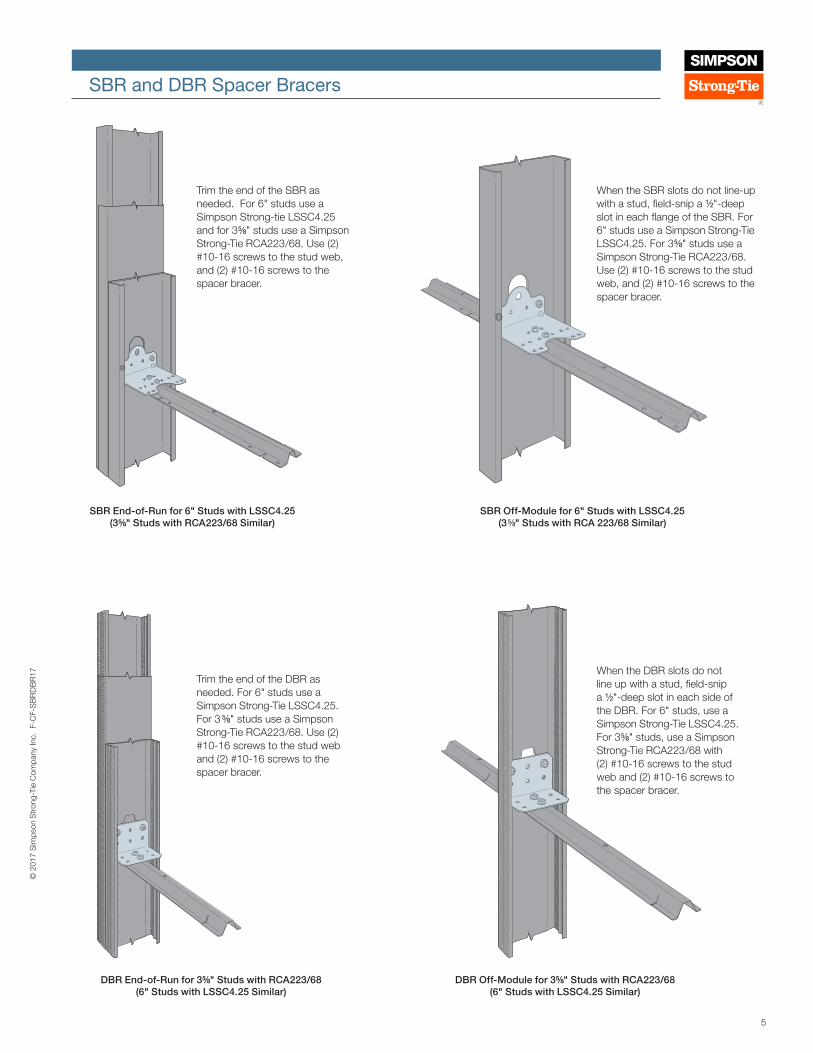
Trim the end of the SBR as needed. For 6" studs use a Simpson Strong-tie LSSC4.25 and for 3 5/8" studs use a Simpson Strong-Tie RCA223 /68. Use (2) #10-16 screws to the stud web, and (2) #10-16 screws to the spacer bracer.
When the SBR slots do not line-up with a stud, field-snip a 1/2"-deep slot in each flange of the SBR. For 6" studs use a Simpson Strong-Tie LSSC4.25. For 3 5/8" studs use a Simpson Strong-Tie RCA223 /68. Use (2) #10-16 screws to the stud web, and (2) #10-16 screws to the spacer bracer.
SBR End-of-Run for 6" Studs with LSSC4.25 (3 5/8" Studs with RCA223 /68 Similar)Typical SBR End-of-Run Installation
Typical SBR Off-Module InstallationSBR Off-Module for 6" Studs with LSSC4.25
(3 5/8" Studs with RCA 223 /68 Similar)
Trim the end of the DBR as needed. For 6" studs use a Simpson Strong-Tie LSSC4.25. For 3 5/8" studs use a Simpson Strong-Tie RCA223 /68. Use (2) #10-16 screws to the stud web and (2) #10-16 screws to the spacer bracer.
DBR End-of-Run for 3 5/8" Studs with RCA223 /68 (6" Studs with LSSC4.25 Similar)Typical DBR End-of-Run Installation
When the DBR slots do not line up with a stud, field-snip a 1/2"-deep slot in each side of the DBR. For 6" studs, use a Simpson Strong-Tie LSSC4.25. For 3 5/8" studs, use a Simpson Strong-Tie RCA223 /68 with (2) #10-16 screws to the stud web and (2) #10-16 screws to the spacer bracer.
DBR Off-Module for 3 5/8" Studs with RCA223 /68 (6" Studs with LSSC4.25 Similar)
Typical DBR Off-Module Installation
6
© 2
017
Sim
pson
Str
ong-
Tie
Com
pany
Inc.
F-C
F-S
BR
DB
R17
SBR and DBR Spacer Bracers
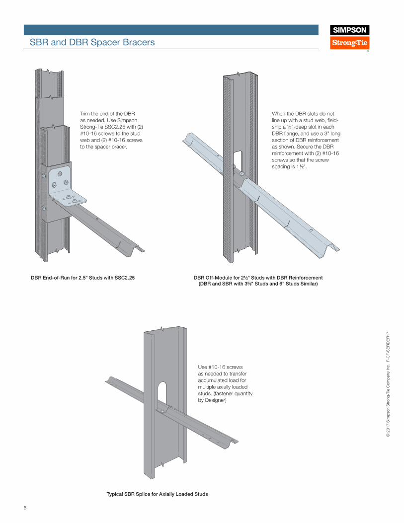
DBR Off-Module for 2 1/2" Studs with DBR Reinforcement (DBR and SBR with 3 5/8" Studs and 6" Studs Similar)Typical DBR Off-Module Installation
When the DBR slots do not line up with a stud web, field-snip a ½"-deep slot in each DBR flange, and use a 3" long section of DBR reinforcement as shown. Secure the DBR reinforcement with (2) #10-16 screws so that the screw spacing is 1 1/2".
SBR Splice
Use #10-16 screws as needed to transfer accumulated load for multiple axially loaded studs. (fastener quantity by Designer)
Typical SBR Splice for Axially Loaded Studs
Typical DBR End-of-Run InstallationDBR End-of-Run for 2.5" Studs with SSC2.25
Trim the end of the DBR as needed. Use Simpson Strong-Tie SSC2.25 with (2) #10-16 screws to the stud web and (2) #10-16 screws to the spacer bracer.
7
© 2
017
Sim
pson
Str
ong-
Tie
Com
pany
Inc.
F-C
F-S
BR
DB
R17
SBR and DBR Spacer Bracers
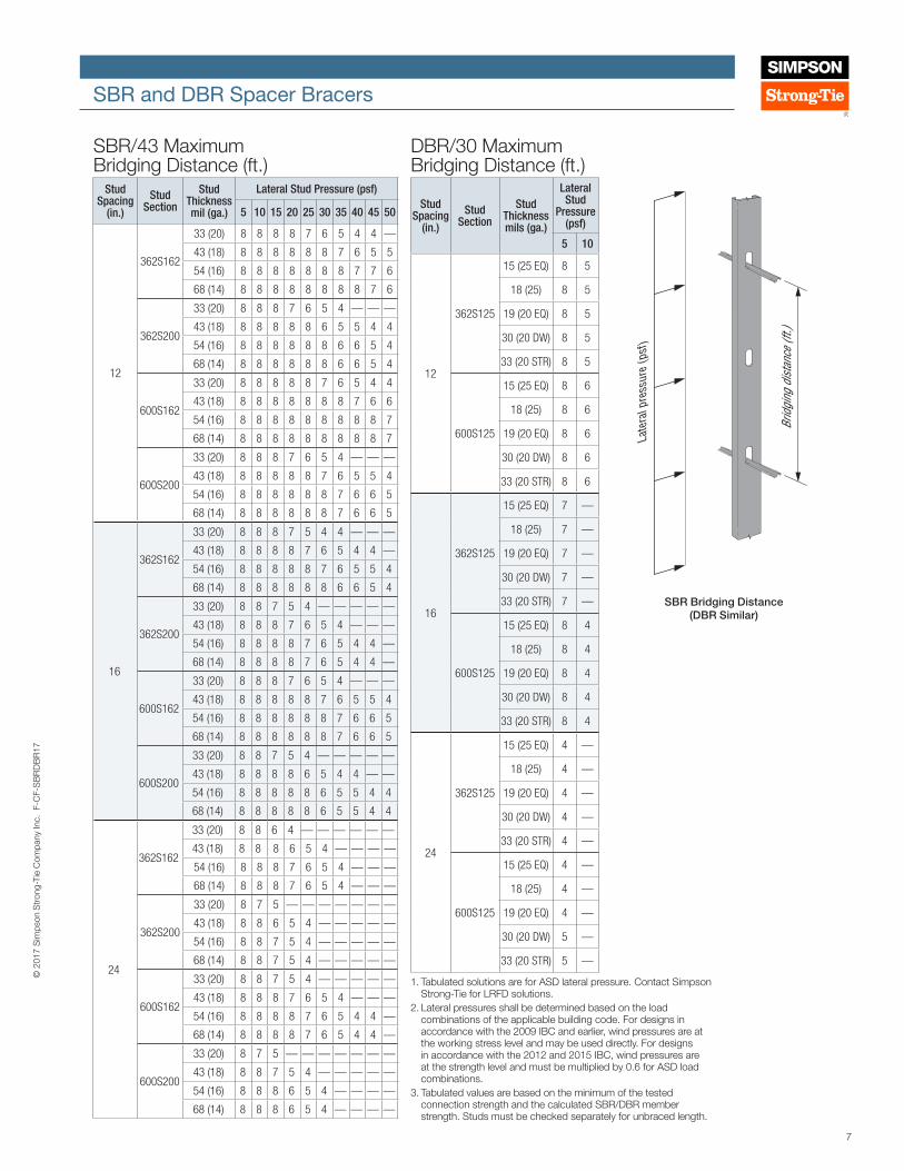
SBR/43 Maximum Bridging Distance (ft.)
Stud Spacing
(in.)
Stud Section
Stud Thickness mil (ga.)
Lateral Stud Pressure (psf)
5 10 15 20 25 30 35 40 45 50
12
362S162
33 (20) 8 8 8 8 7 6 5 4 4 —
43 (18) 8 8 8 8 8 8 7 6 5 5
54 (16) 8 8 8 8 8 8 8 7 7 6
68 (14) 8 8 8 8 8 8 8 8 7 6
362S200
33 (20) 8 8 8 7 6 5 4 — — —
43 (18) 8 8 8 8 8 6 5 5 4 4
54 (16) 8 8 8 8 8 8 6 6 5 4
68 (14) 8 8 8 8 8 8 6 6 5 4
600S162
33 (20) 8 8 8 8 8 7 6 5 4 4
43 (18) 8 8 8 8 8 8 8 7 6 6
54 (16) 8 8 8 8 8 8 8 8 8 7
68 (14) 8 8 8 8 8 8 8 8 8 7
600S200
33 (20) 8 8 8 7 6 5 4 — — —
43 (18) 8 8 8 8 8 7 6 5 5 4
54 (16) 8 8 8 8 8 8 7 6 6 5
68 (14) 8 8 8 8 8 8 7 6 6 5
16
362S162
33 (20) 8 8 8 7 5 4 4 — — —
43 (18) 8 8 8 8 7 6 5 4 4 —
54 (16) 8 8 8 8 8 7 6 5 5 4
68 (14) 8 8 8 8 8 8 6 6 5 4
362S200
33 (20) 8 8 7 5 4 — — — — —
43 (18) 8 8 8 7 6 5 4 — — —
54 (16) 8 8 8 8 7 6 5 4 4 —
68 (14) 8 8 8 8 7 6 5 4 4 —
600S162
33 (20) 8 8 8 7 6 5 4 — — —
43 (18) 8 8 8 8 8 7 6 5 5 4
54 (16) 8 8 8 8 8 8 7 6 6 5
68 (14) 8 8 8 8 8 8 7 6 6 5
600S200
33 (20) 8 8 7 5 4 — — — — —
43 (18) 8 8 8 8 6 5 4 4 — —
54 (16) 8 8 8 8 8 6 5 5 4 4
68 (14) 8 8 8 8 8 6 5 5 4 4
24
362S162
33 (20) 8 8 6 4 — — — — — —
43 (18) 8 8 8 6 5 4 — — — —
54 (16) 8 8 8 7 6 5 4 — — —
68 (14) 8 8 8 7 6 5 4 — — —
362S200
33 (20) 8 7 5 — — — — — — —
43 (18) 8 8 6 5 4 — — — — —
54 (16) 8 8 7 5 4 — — — — —
68 (14) 8 8 7 5 4 — — — — —
600S162
33 (20) 8 8 7 5 4 — — — — —
43 (18) 8 8 8 7 6 5 4 — — —
54 (16) 8 8 8 8 7 6 5 4 4 —
68 (14) 8 8 8 8 7 6 5 4 4 —
600S200
33 (20) 8 7 5 — — — — — — —
43 (18) 8 8 7 5 4 — — — — —
54 (16) 8 8 8 6 5 4 — — — —
68 (14) 8 8 8 6 5 4 — — — —
DBR/30 Maximum Bridging Distance (ft.)
Stud Spacing
(in.)
Stud Section
Stud Thickness mils (ga.)
Lateral Stud
Pressure (psf)
5 10
12
362S125
15 (25 EQ) 8 5
18 (25) 8 5
19 (20 EQ) 8 5
30 (20 DW) 8 5
33 (20 STR) 8 5
600S125
15 (25 EQ) 8 6
18 (25) 8 6
19 (20 EQ) 8 6
30 (20 DW) 8 6
33 (20 STR) 8 6
16
362S125
15 (25 EQ) 7 —
18 (25) 7 —
19 (20 EQ) 7 —
30 (20 DW) 7 —
33 (20 STR) 7 —
600S125
15 (25 EQ) 8 4
18 (25) 8 4
19 (20 EQ) 8 4
30 (20 DW) 8 4
33 (20 STR) 8 4
24
362S125
15 (25 EQ) 4 —
18 (25) 4 —
19 (20 EQ) 4 —
30 (20 DW) 4 —
33 (20 STR) 4 —
600S125
15 (25 EQ) 4 —
18 (25) 4 —
19 (20 EQ) 4 —
30 (20 DW) 5 —
33 (20 STR) 5 —
Brid
ging
dist
ance
(ft.)
Late
ral p
ress
ure
(psf
)
SBR Lateral PressureSBR Bridging Distance(DBR Similar)
1. Tabulated solutions are for ASD lateral pressure. Contact Simpson Strong-Tie for LRFD solutions.
2. Lateral pressures shall be determined based on the load combinations of the applicable building code. For designs in accordance with the 2009 IBC and earlier, wind pressures are at the working stress level and may be used directly. For designs in accordance with the 2012 and 2015 IBC, wind pressures are at the strength level and must be multiplied by 0.6 for ASD load combinations.
3. Tabulated values are based on the minimum of the tested connection strength and the calculated SBR/DBR member strength. Studs must be checked separately for unbraced length.

This flier is effective until June 30, 2019, and reflects information available as of January 1, 2017. This information is updated periodically and should not be relied upon after June 30, 2019. Contact Simpson Strong‑Tie for current information and limited warranty or see strongtie.com.
© 2017 Simpson Strong‑Tie Company Inc. • P.O. Box 10789, Pleasanton, CA 94588 F-CF-SBRDBR17 1/17 exp. 6/19
(800) 999-5099strongtie.com
SBR and DBR Spacer Bracers
Given • 2015 IBC (ASCE 7-10 and AISI S100-2012) • 600S162-54 (50 ksi) studs at 24" o.c., 10' stud height
o Mid-point bracing (5' o.c.) o Distance from shear center to mid-plane of web, m = 0.663 in. (2013 AISI Manual, Table I-2)
• Wind design pressure = 34 psf• Pra = Required ASD axial load = 3,000 lb.
Axially Loaded StudRequired brace strength (AISI S100, Eq. D3.3-1) Prb = 0.01Pra = (0.01)(3,000 lb.) = 30 lb.
Required brace stiffness (AISI S100, Eq. D3.3-2a) βrb = (2[4-(2/n)]/Lb)(ΩPra) = (2[4-(2/1)]/60)(2)(3,000) = 400 lb./in.
Check connection strength and stiffness from Strength and Stiffness table (page 4) for the SBR/43 for 6" deep, 54 mil studs
Allowable brace strength = 450 lb. > 30 lb. OK Allowable brace stiffness = 840 lb./in. > 400 lb./in. OK
Check member strength from Allowable Strengths table (page 4) for the SBR/43 for 24" o.c.
Pa (24" o.c.) = Allowable member strength = 618 lb. > 30 lb. OK
Note: Member stiffness and the effects of accumulated load for multiple axially loaded studs have not been accounted for in the above calculations. Reference CFSEI Tech Note W400-16 for additional guidance on these topics.
Laterally Loaded StudASD Design load tributary to brace: W = (0.6)(34 psf)(2 ft.)(5 ft.) = 204 lb.
Note: 2015 IBC load combinations for ASD include a factor of 0.6
Required flange force (AISI S100 Eq. D3.2.1-3) PL1 = -PL2 = 1.5(m/d)W = (1.5)(0.663 in./6 in.)(204 lb.) = 33.8 lb.
Torsional moment Mz = PL1d = -PL2d = (33.8)(6) = 202.8 in.-lb.
Moment applied to bridging member Mm = 0.64Mz = (0.64)(202.8) = 129.8 in.-lb.
Note: The 0.64 factor is from an analysis of a five-span continuous beam that is loaded with equal support moments (Reference AISI Design Guide D110-07, page 2-9, Figure 2-6)
Check connection strength from Strength and Stiffness table (page 4) for the SBR/43 for 6" deep, 54 mil studs Allowable torsional moment = 365 in.-lb. > 202.8 in.-lb. OK
Check member strength from Allowable Strengths table (page 4) for the SBR/43 for 24" o.c. Ma (24" o.c.) = Allowable moment = 360 in.-lb. > 129.8 in.-lb. OK
Combined-Loading Check of Connection(Pbr /Allowable brace strength) + (Mz/Allowable torsional moment) ≤ 1.0 (30 lb./450 lb.) + (202.8 in.-lb./365 in.-lb.) = 0.62 < 1.0 OK
Combined-Loading Check of Bridging MemberReference AISI Eqs. C5.2.1-1, C5.2.1-2, or Eq. C52.1-3 as applicable. For this condition, Eq. C5.2.1-3 applies.
10'
5'
SBR Loads
Note: The allowable strengths given in the Allowable Strengths table (page 4) have been converted to nominal strengths by multiplying by Ω=2.0.
ΩcP ΩbM ---------------- + -------------- ≤ 1.0 Pn Mn
Pn = 2Pa Mn = 2Ma
1.8 (30) 1.67 (129.8) ------------------- + ---------------------------- = 0.34 < 1.0 OK 2 (618) 2 (360)


![Stewart, Amy (DBR) · From: Bannister, Jorge (DBR) To: Stewart, Amy (DBR) Cc: Taylor, Tina (DBR); Desilets, LeeAnn (DBR) Subject: FW: [EXTERNAL] : Food Trucks Date: Friday, February](https://img.dokumen.tips/doc/110x75/5fb3a34c68602c67914aec27/stewart-amy-dbr-from-bannister-jorge-dbr-to-stewart-amy-dbr-cc-taylor.jpg)