Embed Size (px)
Citation preview

INSTALLATION TESTING REQUIREMENTS Preface, TP 76900MP SBC Local Exchange Carriers December 1, 2000
i
SBC LEC
TECHNICAL PUBLICATION
NOTICE
This Technical Publication is published by the SBC Local Exchange Carriers (SBC LECs) as a guide for the designers and manufacturers of central office equipment, including the providing of engineering and installation services relating to SBC LEC communications systems or equipment. It is not intended to provide complete design specifications or parameters nor the assurance of the quality of performance of such equipment.
The SBC LEC reserves the right to revise this Technical Publication for any reason, including, but not limited to, conformity with criteria or standards promulgated by governmental or regulatory agencies; utilization of advances in the state of the technical arts; or to reflect changes in the design of equipment techniques or services described or referred to herein.
The techniques or equipment characteristics disclosed herein may be covered by patents of the SBC LEC or others. No license expressed or implied is hereby granted. This document is not to be construed as a suggestion to any manufacturer to modify or change any of its products, nor does this document represent any commitment by the SBC LEC or affiliates thereof to purchase any products whether or not it provides the described characteristics.
In performing services hereunder, the Installation Supplier agrees to limit its activities to those necessary and essential to performing such services, to not interfere with or misuse any non-SBC LEC equipment or facilities on or adjacent to the SBC LEC’s facilities, to refrain from in any manner accessing customer lines to which customer has access and to indemnify and hold harmless the SBC LEC for any inappropriate use of material or information.
COPYRIGHT 2000 - SBC Local Exchange Carriers, ALL RIGHTS RESERVED
[END OF SECTION]
Checklist, TP 76900MP INSTALLATION TESTING REQUIREMENTS December 1, 2000 SBC Local Exchange Carriers
ii
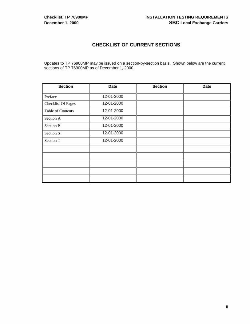
CHECKLIST OF CURRENT SECTIONS
Updates to TP 76900MP may be issued on a section-by-section basis. Shown below are the current sections of TP 76900MP as of December 1, 2000.
Section Date Section Date
Preface 12-01-2000
Checklist Of Pages 12-01-2000
Table of Contents 12-01-2000
Section A 12-01-2000
Section P 12-01-2000
Section S 12-01-2000
Section T 12-01-2000

INSTALLATION TESTING REQUIREMENTS Table of Contents, TP 76900MP SBC Local Exchange Carriers December 1, 2000
iii
TABLE OF CONTENTS CONTENTS PAGE
SECTION A--INTRODUCTION...........................................................................................................A-1
1. GENERAL ..............................................................................................................................A-1 1.1. Introduction.............................................................................................................................A-1 1.2. Definitions...............................................................................................................................A-1 1.2. Proprietary Information ...........................................................................................................A-2 1.3. Ordering Information...............................................................................................................A-2 1.4. Comments On TP 76900MP ..................................................................................................A-2
2. INFORMATION COMMON TO ALL SECTIONS....................................................................A-3 2.1. General...................................................................................................................................A-3 2.2. Before Start of Test Procedure...............................................................................................A-3 2.3. During Test Procedure ...........................................................................................................A-4 2.4. Post Job Test Activity .............................................................................................................A-4
SECTION P--POWER EQUIPMENT...................................................................................................P-1
1. GENERAL ..............................................................................................................................P-2 1.1. Introduction.............................................................................................................................P-2 1.2. General Requirements ...........................................................................................................P-2
2. STANDBY ENGINE ALTERNATOR SETS ............................................................................P-2 2.1. General...................................................................................................................................P-2 2.2. Test Requirements .................................................................................................................P-2
3. FUEL TANK............................................................................................................................P-4 3.1. Primary Tank ..........................................................................................................................P-4 3.2. Day Tank ................................................................................................................................P-4 3.3. Fuel Monitoring System..........................................................................................................P-5
4. AUTOMATIC TRANSFER SWITCH ......................................................................................P-5 4.1. Test Requirements .................................................................................................................P-5
5. POWER CONTROL AND DISTRIBUTION BAYS .................................................................P-5 5.1. Test Requirements .................................................................................................................P-5
6. RECTIFIERS ..........................................................................................................................P-6 6.1. Test Requirements .................................................................................................................P-6
7. BATTERIES............................................................................................................................P-7 7.1. Test Requirements - Flooded Cells ........................................................................................P-7 7.2. Test Requirements - VRLA ....................................................................................................P-8
8. MICROPROCESSOR CONTROLLER/REMOTE MONITOR ................................................P-8 8.1. Test Requirements .................................................................................................................P-8
9. CONVERTER PLANTS..........................................................................................................P-9 9.1. Test Requirements .................................................................................................................P-9

Table of Contents, TP 76900MP INSTALLATION TESTING REQUIREMENTS December 1, 2000 SBC Local Exchange Carriers
iv
10. INVERTERS......................................................................................................................... P-10 10.1. Test Requirements............................................................................................................... P-10
11. UNINTERRUPTIBLE POWER SYSTEMS........................................................................... P-11 11.1. Test Requirements............................................................................................................... P-11 11.2. Batteries ............................................................................................................................... P-11 11.3. Initial Startup ........................................................................................................................ P-12 11.4. Distribution ........................................................................................................................... P-13 11.5. Grounding ............................................................................................................................ P-13 11.6. Emergency Shutdown .......................................................................................................... P-13 11.7. Alarms .................................................................................................................................. P-13
12. UPS LOAD TESTING .......................................................................................................... P-14 12.1. General............................................................................................................................... P-14 12.2. Full Load............................................................................................................................. P-14 12.3. Discharge Test #1 .............................................................................................................. P-14 12.4. Recharge Test #1............................................................................................................... P-15 12.5. Discharge Test #2 .............................................................................................................. P-15 12.6. Recharge Test #2 (Timed Recharge)................................................................................. P-15 12.7. Timed Discharge Test ........................................................................................................ P-16 12.8. Recharge Following Timed Discharge ............................................................................... P-16 12.9. Standby AC Power Test (Power Failure Simulation).......................................................... P-16 12.10. Standby AC Power Test with Emergency Alternator (Power Failure Simulation)............... P-17 12.11. Recharge for Connected Load Test ................................................................................... P-17 12.12. Connected Load Test ......................................................................................................... P-18
SECTION S--SWITCHING EQUIPMENT ........................................................................................... S-1
1. GENERAL .............................................................................................................................. S-1 1.1. Introduction ............................................................................................................................ S-1
2. TEST REQUIREMENTS........................................................................................................ S-1 2.1. General .................................................................................................................................. S-1 2.2. Frame Grounding................................................................................................................... S-1 2.3. System Diagnostics................................................................................................................ S-2 2.4. Operational Tests................................................................................................................... S-2 2.5. System Recovery ................................................................................................................... S-2 2.6. Software Evaluation ............................................................................................................... S-2 2.7. Alarms .................................................................................................................................... S-3 2.8. Miscellaneous Hardware........................................................................................................ S-3
SECTION T--TRANSMISSION EQUIPMENT .................................................................................... T-1
1. GENERAL .............................................................................................................................. T-1 1.1. Introduction ............................................................................................................................ T-1
2. TEST REQUIREMENTS........................................................................................................ T-1 2.1. General .................................................................................................................................. T-1 2.2. Alarms .................................................................................................................................... T-1 2.3. Synchronization Leads ........................................................................................................... T-1 2.4. Power ..................................................................................................................................... T-2 2.5 Grounding..........................................................................................................................T-2

INSTALLATION TESTING REQUIREMENTS Table of Contents, TP 76900MP SBC Local Exchange Carriers December 1, 2000
v
2.5. Electrical Interface Cabling.....................................................................................................T-2 2.6. Fiber Interface Cabling ...........................................................................................................T-2 2.7. System Diagnostics ................................................................................................................T-2 2.8. Operational Tests ...................................................................................................................T-2 2.9. Equipment Specific Test Requirements .................................................................................T-3 2.10. Software .................................................................................................................................T-3
[END OF SECTION]

INSTALLATION TESTING REQUIREMENTS Section A, TP 76900MP SBC Local Exchange Carriers December 1, 2000
A-1
SECTION A -- INTRODUCTION
1. GENERAL ..............................................................................................................................A-1
1.1. Introduction.............................................................................................................................A-1 1.2. Definitions...............................................................................................................................A-1 1.3. Proprietary Information ...........................................................................................................A-2 1.4. Ordering Information...............................................................................................................A-2 1.5. Comments On TP 76900MP ..................................................................................................A-2
2. INFORMATION COMMON TO ALL SECTIONS....................................................................A-2
2.1. General...................................................................................................................................A-2 2.2. Test Equipment ......................................................................................................................A-3 2.3. Before Start of Test Procedure...............................................................................................A-4 2.4. During Test Procedure ...........................................................................................................A-4 2.5. Post Job Test Activity .............................................................................................................A-4
1. GENERAL
1.1. Introduction
1.1.1 TP 76900MP, SBC Local Exchange Carriers Installation Testing Requirements, provides Installation Suppliers with the necessary testing requirements that shall be performed before turnover of telecommunications equipment to the SBC Local Exchange Carriers (LECs).
1.1.2 Changes in this issue of Section A of TP 76900MP are summarized in Table A-1.
1.1.3 TP 76900MP applies to installation jobs in Ameritech, Pacific Bell, Nevada Bell, Southern New England Telephone and Southwestern Bell.
1.1.4 SBC reserves the right, without prior notice, to revise TP 76900MP for any reason.
1.1.5 The SBC LECs assume no responsibility for any costs incurred by a given manufacturer or Supplier in conforming to the requirements of TP 76900MP. Further, conformance to all requirements delineated in this document does not constitute a guarantee of acceptance of a given Supplier’s product/service for use in the SBC LECs.
1.2. Definitions
1.2.1 Definitions of certain terms used in TP 76900MP are as follows:
a) Central office - SBC LEC owned or leased premises where network elements are located.
b) SBC Local Exchange Carrier (LEC) - Ameritech, Pacific Bell, Nevada Bell, Southern New England Telephone and Southwestern Bell.
c) SBC LEC Equipment Engineer - the SBC LEC equipment engineering organization representative or the SBC LEC real estate management representative who is directly responsible for the installation in progress and who has overall responsibility for job completion and acceptance.

Section A, TP 76900MP INSTALLATION TESTING REQUIREMENTS December 1, 2000 SBC Local Exchange Carriers
A-2
d) SBC LEC Representative - The SBC LEC person(s), designated by the SBC LEC Equipment Engineer, who has responsibility for the daily coordination between the Installation Supplier’s on-site personnel and the SBC LEC.
e) Shall - Something that is mandatory and subject to audit.
f) Should - Something that is recommended.
g) Yellow wallet - A standard accordion folder with cover, minimum size 9” X 12”, in which job documentation to remain at the site shall be filed.
1.3. Proprietary Information
1.3.1 All proprietary documents referenced in TP 76900MP are available through signed nondisclosure agreements or as detailed in current contracts between the SBC LEC and the Installation Supplier.
1.4. Ordering Information
1.4.1 Internet access is available for downloading electronic copies of TP 76900MP and other SBC LEC references. Information concerning internet access can be obtained from:
Gwen Schumaker 2200 N. Greenville, Room 3E
Richardson, TX 75082 E-mail: [email protected]
1.4.2 Paper copies of TP 76900MP or other SBC LEC technical publications can be ordered from:
Technical Publication Information 530 McCullough, Room 2-E-02
San Antonio, TX 78215 1.4.3 Non-SBC LEC publications referenced herein should be obtained from the originator of the
publication.
1.5. Comments On TP 76900MP
1.5.1 Comments on TP 76900MP should be submitted in writing to:
Jamie McCammon
201 S. Douglas, Room 111 El Segundo, CA 90245
E-mail: [email protected]
2. INFORMATION COMMON TO ALL SECTIONS
2.1. General
2.1.1 Common information is consolidated in Section A to eliminate repetition and reduce the length of each section. Section A applies to and shall be referenced along with the subsequent technology-specific Sections P, S and T.

INSTALLATION TESTING REQUIREMENTS Section A, TP 76900MP SBC Local Exchange Carriers December 1, 2000
A-3
2.1.2 Table A-2 contains a list of SBC LEC references that may be required to complete certain tests in this document. The latest issue of all references shall be used. The Installation Supplier shall have access to these references during testing of installed equipment.
2.1.3 Unless otherwise indicated on the Checklist of Current Sections, TP 76900MP requirements become effective for jobs completing 90 days or more after the section issue date. The Checklist of Current Sections at the front of TP 76900MP indicates the issue date and the effective date of each section. Revisions will be issued on a section-by-section basis. Along with the revised section(s), an updated Checklist of Current Sections will be issued to indicate the current issue date and effective date for each section.
2.1.4 Approved departures from TP 76900MP shall be documented in the yellow wallet at the job site.
2.1.5 Installation shall be performed in accordance with TP 76300MP, SBC Local Exchange Carrier Installation Requirements.
2.1.6 TP 76900MP is applicable to all installation activities in the central office environments of the SBC LECs, regardless of who performs the work. This includes SBC LEC personnel, Competitive Local Exchange Carrier (CLEC) personnel, as well as any contracted Installation Suppliers performing work for the SBC LEC or on behalf of CLECs. For installations at Public Safety Answering Point (PSAP) locations, refer to TP 76911MP.
2.1.7 The Installation Supplier shall have a current TP 76900MP available at the job site (in paper or electronic form) during testing of installed equipment.
2.1.8 The requirements specified herein are the responsibility of the Installation Supplier.
2.1.9 The SBC LEC may elect to perform joint testing with the Installation Supplier.
2.1.10 Standard alarm sets and testing compliance covenants are found in BSP 801-601-900MP. It is required that all alarms connected and tested shall be in strict adherence to information contained therein. It is further required that the testing of standard alarm sets for all provisioned equipment be completed prior to job acceptance. All Network Element (NE) alarms tested into NMA/OSS shall be documented on the Test Record (see TP 76300MP) and placed in the yellow wallet. Reference: BSP 801-601-900MP, Section A.03.0.
2.1.11 Additional site or technology specific testing requirements shall be agreed upon and approved by the SBC LEC Equipment Engineer.
2.1.12 In addition to the SBC LEC requirements, the Installation Supplier shall be responsible for adhering to building codes, national and local electrical codes or other ordinances, statutes, rules, or governmental regulations applicable to the job site. Where more than one requirement applies to any matter related to personnel safety or property protection, the strictest applicable requirement applies.
2.2. Test Equipment
2.2.1 With prior approval, the Installation Supplier may be permitted to use apparatus provided by the job specification (i.e., test equipment, meters, transmission measuring sets, etc.) as

Section A, TP 76900MP INSTALLATION TESTING REQUIREMENTS December 1, 2000 SBC Local Exchange Carriers
A-4
required for the performance of necessary tests to ensure proper functioning of added or modified equipment. The Installation Supplier shall use properly calibrated test equipment.
2.2.2 Test equipment owned by the SBC LEC for equipment maintenance will not be available for installation purposes except in specific cases where prior arrangements are made with the SBC LEC.
2.2.3 Any test equipment and/or spare equipment provided, as part of the job is the responsibility of the Installation Supplier. In most instances, the test equipment will not be turned over to the SBC LEC until the associated equipment is turned over. However, upon request, the SBC LEC personnel may have access to the test equipment to permit the checking of circuit features or to allow the testing of added equipment to which test circuits can access.
2.3. Before Start of Test Procedure
2.3.1 Precautions shall be taken to prevent personnel injury, equipment damage and service interruptions.
2.3.2 Any testing procedure, including any hardware or software changes, that affects in-service equipment shall be coordinated with the SBC LEC Representative. A Method of Procedure (MOP) per TP 76300MP shall be approved for the testing. Before starting testing procedures covered by any section in this TP, the Installation Supplier shall make arrangements to have the required test equipment at the job site. The Installation Supplier shall verify that all user’s guides, drawings and other documentation are accurate and on site for testing.
2.4. During Test Procedure
2.4.1 Tests shall be performed in the proper sequence for the item being tested.
2.4.2 Unless specified otherwise herein, test results for each item tested shall be documented on the Test Record and placed in the yellow wallet, per TP 76300MP.
2.4.3 Before “turn over” of the equipment to the SBC LEC, the Installation Supplier, shall correct any defects found during testing. Any corrective action required does not constitute a reason for extension of the job interval.
2.4.4 Before testing affected equipment, the Installation Supplier shall apply all SBC LEC approved and identified class A/AC product changes in accordance with TP 76300MP. Any authorized product change notices (PCNs) released during the installation interval shall be applied and tested before turnover. The Installation Supplier shall report the application of product changes per TP 76300MP.
2.5. Post Job Test Activity
2.5.1 The SBC LEC reserves the right to audit compliance to the requirements in this document. The Installation Supplier shall correct any performance defects within 30 days of notification.
2.5.2 The SBC LEC Representative must approve post job testing activity.
2.5.3 Unless specified otherwise herein, revised test results shall be documented on the Test Record, per TP 76300MP.

INSTALLATION TESTING REQUIREMENTS Section A, TP 76900MP SBC Local Exchange Carriers December 1, 2000
A-5
TABLE A-1 – SUMMARY OF CHANGES IN SECTION A
Change Item in 05/01/1999 Issue Item in this Issue
Revised 1.1.2-1.1.4 1.2.1 (a-g) 1.3.1 1.4.1 2.1.2 2.1.3 2.1.6 2.1.9 2.2.1 2.3.2 2.3.4 Table A-1
1.1.2-1.1.4 1.2.1 (a-g) 1.3.1 1.4.1 2.1.2 2.1.3 2.1.7 2.1.10 2.3.1 2.3.2 2.4.4 Table A-2
Deleted ------
Added ------- Table A-1 2.1.4 2.2.1 2.2.2 2.2.3
TABLE A-2 – REFERENCES IN TP 76900MP
Reference Title Current Issue
TP 76300MP SBC LEC Installation Requirements 11/1/2000
BSP 801-601-900MP SBC LEC Alarm Standards Issue 4

Section A, TP 76900MP INSTALLATION TESTING REQUIREMENTS December 1, 2000 SBC Local Exchange Carriers
A-6
[END OF SECTION]

INSTALLATION TESTING REQUIREMENTS Section P, TP 76900MP SBC Local Exchange Carriers December 1, 2000
P-1
SECTION P--POWER EQUIPMENT CONTENTS PAGE
1. GENERAL ..............................................................................................................................P-2
1.1. Introduction.............................................................................................................................P-2 1.2. General Requirements ...........................................................................................................P-2
2. standby ENGINE/alternator sets ............................................................................................P-2
2.1. General...................................................................................................................................P-2 2.2. Test Requirements .................................................................................................................P-2
3. fuel Tank.................................................................................................................................P-5
3.1. Primary Tank ..........................................................................................................................P-5 3.2. Day Tank ................................................................................................................................P-5 3.3. Fuel Monitoring System..........................................................................................................P-5
4. AUTOMATIC TRANSFER SWITCH ......................................................................................P-5
4.1. Test Requirements .................................................................................................................P-5
5. POWER CONTROL AND DISTRIBUTION BAYS .................................................................P-6
5.1. Test Requirements .................................................................................................................P-6
6. RECTIFIERS ..........................................................................................................................P-7
6.1. Test Requirements .................................................................................................................P-7
7. BATTERIES............................................................................................................................P-8
7.1. Test Requirements - Flooded Cells ........................................................................................P-8 7.2. Test Requirements - VRLA ....................................................................................................P-8
8. MICROPROCESSOR CONTROLLER...................................................................................P-9
8.1. Test Requirements .................................................................................................................P-9
9. CONVERTER PLANTS........................................................................................................P-10
9.1. Test Requirements ...............................................................................................................P-10
10. INVERTERS .........................................................................................................................P-10
10.1. Test Requirements ...............................................................................................................P-10
11. UNINTERRUPTIBLE POWER SYSTEMS...........................................................................P-11
11.1. Test Requirements ...............................................................................................................P-11 11.2. Batteries ...............................................................................................................................P-12 11.3. Initial Startup.........................................................................................................................P-12 11.4. Distribution............................................................................................................................P-13 11.5. Grounding.............................................................................................................................P-14 11.6. Emergency Shutdown...........................................................................................................P-14 11.7. Alarms ..................................................................................................................................P-14

Section P, TP 76900MP INSTALLATION TESTING REQUIREMENTS December 1, 2000 SBC Local Exchange Carriers
P-2
12. UPS LOAD TESTING .......................................................................................................... P-14
12.1. General ................................................................................................................................ P-14 12.2. Full Load .............................................................................................................................. P-14 12.3. Discharge Test #1................................................................................................................ P-15 12.4. Recharge Test #1................................................................................................................. P-15 12.5. Discharge Test #2................................................................................................................ P-15 12.6. Recharge Test #2 (Timed Recharge) .................................................................................. P-16 12.7. Timed Discharge Test.......................................................................................................... P-16 12.8. Recharge Following Timed Discharge ................................................................................. P-16 12.9. Standby AC Power Test (Power Failure Simulation) ........................................................... P-17 12.10.Standby AC Power Test with Emergency Alternator (Power Failure Simulation)................ P-17 12.11.Recharge for Connected Load Test .................................................................................... P-18 12.12.Connected Load Test .......................................................................................................... P-18
1. GENERAL
1.1. Introduction
1.1.1 This section of TP 76900MP covers installation testing requirements for power equipment.
1.1.2 Changes in this issue of Section P of TP 76900MP are summarized in Table P-1.
1.2. General Requirements
1.2.1 Section A of TP 76900MP shall be used in conjunction with this Section P.
1.2.2 Testing associated with simulated AC failures, transfer of AC from commercial AC to engine/alternator set shall be coordinated with the SBC LEC Representative and will require a MOP.
2. STANDBY ENGINE/ALTERNATOR SETS
2.1. General
2.1.1 Standby engine/alternator sets shall be installed and tested in a manner that ensures the engine is ready to be run in its normal environment, and that such a run will not damage the engine or the alternator, and that the engine and alternator will perform as designed.
2.2. Test Requirements
2.2.1 The following tests are required and shall be performed in accordance with detail specifications. These tests may be jointly performed with the SBC LEC:
a) One step or incremental loading, as required by the SBC LEC Equipment Engineer
b) Prolonged full load run
c) Exhaust system integrity.

INSTALLATION TESTING REQUIREMENTS Section P, TP 76900MP SBC Local Exchange Carriers December 1, 2000
P-3
2.2.2 Tests shall be made on the engine to ensure that:
a) All belts are tight and free from defects
b) The engine/alternator oil is filled to the correct level
c) The engine/alternator oil is free of water and any other impurities
d) The engine/alternator coolant is free of oil and other impurities
e) The engine/alternator coolant is at the proper level
f) The engine/alternator does not have any oil, fuel or coolant leaks
g) The engine/alternator heater operates properly.
2.2.3 Tests shall be made on the engine/alternator to ensure that automatic engine shutdown will occur under each of the following conditions:
a) Local Emergency Stop switch is engaged
b) Remote Emergency Stop switch is engaged
c) Engine/alternator overspeed
d) Engine/alternator coolant high water temperature
e) Engine/alternator low oil pressure
f) Engine/alternator overcrank
g) Alternator voltage exceeds over voltage threshold
h) Alternator voltage does not meet under voltage threshold
i) Low engine/alternator coolant level.
2.2.4 The following safety devices shall be dynamically tested to ensure proper operation:
a) Engine/alternator low oil pressure switch
b) Engine/alternator overcrank control system
c) Engine/alternator coolant high water temperature sensor.
2.2.5 Tests shall be made on the engine/alternator start battery charger to ensure that the start battery is floating at the correct voltage.
2.2.6 Tests shall be made on the engine/alternator environment to ensure that:
a) The engine/alternator has adequate air flow for cooling and for combustion
b) Air intake louvers, if provided, operate correctly
c) Radiator exhaust louvers, if provided, operate correctly
d) Noise levels comply with local ordinances.
2.2.7 Tests shall be made on the engine/alternator alarms to ensure that all alarms are wired and tested to:

Section P, TP 76900MP INSTALLATION TESTING REQUIREMENTS December 1, 2000 SBC Local Exchange Carriers
P-4
a) The local visual alarm indicator
b) The local audible alarm enunciator
c) The remote alarm panel
d) The power monitor (when present)
e) Alarm collection system (when present).
2.2.8 The engine/alternator alarms, as defined in BSP 801-601-900MP, Section I, shall be wired and tested to the remote alarm monitoring and surveillance center. These alarms may include some or all of the following:
a) Engine Run
b) Pre Low Oil Pressure
c) Pre High Temperature
d) High Temperature
e) Overspeed
f) Over Crank
g) Over/Under Voltage
h) Low temperature
i) Low Fuel
j) Switch Off Normal
k) Major - Engine/alternator Fail
l) Minor (Summary Alarm)
m) Rectifier Fail (Start Battery Rectifier Fail)
n) Proper Operation
o) Power Fail (AC Commercial Power Failure).
2.2.9 Fuel supply systems shall be tested in a manner that ensures the system is ready to provide fuel to the engine/alternator and will not damage the engine/alternator or the alternator, and that the engine/alternator and alternator will perform as designed.
2.2.10 When a remote radiator has been deployed, the Installation Supplier shall ensure:
a) All belts are tight and free from defects
b) Proper fan rotation
c) Proper water flow
d) Air flow switch operates properly
e) Proper operation of the engine/alternator room exhaust fan.

INSTALLATION TESTING REQUIREMENTS Section P, TP 76900MP SBC Local Exchange Carriers December 1, 2000
P-5
3. FUEL TANK
3.1. Primary Tank
3.1.1 Tests shall be made on the engine/alternator fuel system primary tank to ensure that:
a) All fuel piping is free of leaks
b) The automatic fuel pumping system is of sufficient size and capacity to handle the engine/alternator at engineered capacity.
3.2. Day Tank
3.2.1 Tests shall be made on the diesel engine/alternator fuel system day tank to ensure that:
a) All fuel piping is free of leaks
b) The automatic fuel pumping system is of sufficient size and capacity to handle the engine/alternator at full load
c) Alarm systems operate properly
d) Transfer pump system operates properly.
3.3. Fuel Monitoring System
3.3.1 Tests shall be made on the fuel monitoring system to ensure that the system is programmed and operating properly.
3.3.2 The Installation Supplier shall ensure that the fuel monitoring system can be controlled from:
a) The front panel/keyboard
b) Remote access.
3.3.3 Test shall be made on the fuel monitoring system to ensure that major and minor alarms are transmitted to:
a) The local audible enunciator
b) The local visual alarm display unit
c) The power monitor (when present)
d) The alarm collection systems, and (when present)
e) The remote alarm monitoring and surveillance center.
4. AUTOMATIC TRANSFER SWITCH
4.1. Test Requirements
4.1.1 Tests shall be performed to ensure that the automatic transfer switch (ATS) is wired in such a manner as to have the phase rotation in the same direction when switched from commercial AC to engine/alternator AC.

Section P, TP 76900MP INSTALLATION TESTING REQUIREMENTS December 1, 2000 SBC Local Exchange Carriers
P-6
4.1.2 Tests shall be run to ensure that all front panel lamps on the ATS operate properly according to the manufacturer’s equipment manual.
4.1.3 Tests shall be run to ensure that all programs and timers are set in accordance with the detail specification.
4.1.4 Tests shall be run to ensure that the ATS will automatically, upon loss of commercial AC, start the engine/alternator and switch the AC load to the engine/alternator powered alternator.
4.1.5 Tests shall be performed to ensure that the ATS restores to normal setting upon detecting restoration of commercial AC.
4.1.6 The Installation Supplier shall ensure that, upon engine/alternator failure, the ATS will immediately retransfer to commercial AC, if available.
5. POWER CONTROL AND DISTRIBUTION BAYS
5.1. Test Requirements
5.1.1 Tests shall be run to ensure that:
a) Each fuse position transmits a fuse alarm
b) Meters are calibrated correctly
c) Voltage sensing relays are adjusted correctly
d) Solid state monitors are adjusted properly
e) The high voltage shutdown feature will shut down all rectifiers that are providing current.
5.1.2 Power control and distribution bay alarms shall be tested to:
a) Operate the local visual and audible alarms
b) The power monitor where a monitor/microprocessor is available
c) Ensure alarms are received at the remote alarm monitoring and surveillance center. The alarms that shall be wired and tested are defined in BSP 801-601-900MP, Section I, and may include the following:
1. High Voltage
2. Low Voltage
3. Low-Low Voltage
4. Battery On Discharge
5. Fuse
6. Rectifier Fail
7. Microprocessor Fail (if plant is equipped with a microprocessor)
8. Major

INSTALLATION TESTING REQUIREMENTS Section P, TP 76900MP SBC Local Exchange Carriers December 1, 2000
P-7
9. Minor
6. RECTIFIERS
6.1. Test Requirements
6.1.1 General tests shall be performed on each rectifier to ensure that:
a) All meters are properly calibrated
b) Each rectifier current limits at 110% of rated load
c) Each rectifier will load share and pick up the appropriate portion of the load
d) The DC output current is free of AC ripple, in accordance with Table P-2
e) The Rectifier Fail alarm functions correctly (blown fuse powering control circuitry causes failure)
f) Each rectifier output voltage is adjusted correctly
g) An internal blown fuse prevents the rectifier from operating
h) The rectifier sequence control unit operates properly.
6.1.2 Tests associated with Shutdown and Restart shall be run on each rectifier to ensure that:
a) The internal high-voltage shutdown feature operates properly
b) The automatic restart feature operates properly
c) The external high-voltage shutdown feature operates properly
d) The rectifier automatic restart from the control bay operates properly.
6.1.3 Test associated with simulated commercial power failure and restore shall be run on each rectifier, by turning AC power off and on at the PDSC, to ensure that:
a) Each AC breaker turns off the rectifier as labeled
b) The unit’s current “walk-in” feature operates properly
c) Upon removal of AC, the proper alarms are brought in
d) That upon restoration of AC power, all alarms are retired.
6.1.4 Test to ensure that each rectifier transmits alarms to:
a) The power plant (both visual and audible)
b) The microprocessor, if present
c) The remote alarm monitoring and surveillance center.
6.1.5 When a microprocessor unit is present, tests shall be performed to ensure that:
a) The rectifier output current is monitored
b) The microprocessor can turn the rectifiers on and/or off

Section P, TP 76900MP INSTALLATION TESTING REQUIREMENTS December 1, 2000 SBC Local Exchange Carriers
P-8
c) The microprocessor unit (MPU) monitors the Rectifier Fail Alarm (RFA), as a supplemental and adjunct monitoring operation to the SBC Alarm Network design. (I.e., the RFA shall be monitored directly by an approved alarm collection system and shall not be dependent upon the interactive operation of an intermediate mediation device, such as the MPU, to report a failure).
7. BATTERIES
7.1. Test Requirements - Flooded Cells
7.1.1 Test results for the following items shall be recorded on the Storage Battery Charge Report, per TP 76300MP:
a) Tests shall be made on the batteries prior to initial charge to record individual cell electrolyte specific gravity
b) Individual cell voltages after initial charge, but while still on charge
c) Individual cell electrolyte specific gravity
d) Individual cell inspection for the presence of crystals or other defects
e) Tests shall be made on the batteries to record the individual cell voltages 72 hours after initial charge while on float.
7.1.2 Test results shall be recorded on the Pressure Test Record, per TP 76300MP.
7.1.3 Tests shall be performed on the batteries during a discharge (simulated AC outage) to record (on the Test Record, per TP 76300MP):
a) Individual cell voltages during the discharge
b) Current output, on a per string basis, including existing strings, during a simulated AC outage
c) Current readings on each individual battery drop cable during a discharge.
7.2. Test Requirements - VRLA
7.2.1 Test results for the following items shall be recorded on the Storage Battery Charge Report, per TP 76300MP:
a) Tests shall be made on the batteries prior to initial charge to record individual battery conductance values
b) Individual battery voltages after initial charge, but while still on charge
c) Tests shall be made on the batteries to record the individual battery voltages 72 hours after initial charge while on float.
7.2.2 Tests shall be made on the batteries during a discharge (simulated AC outage) to record (on the Test Record, per TP 76300MP):
a) Individual battery voltages during the discharge

INSTALLATION TESTING REQUIREMENTS Section P, TP 76900MP SBC Local Exchange Carriers December 1, 2000
P-9
b) Current output, on a per string basis, including existing strings, during a simulated AC outage.
8. MICROPROCESSOR CONTROLLER
8.1. Test Requirements
8.1.1 The Installation Supplier shall ensure that the microprocessor controller can be controlled from:
a) The front panel/keyboard
b) Remote access.
8.1.2 The Installation Supplier shall ensure that, when the microprocessor fails, it transmits a Microprocessor Fail alarm.
8.1.3 If a sequence control is provided, the Installation Supplier shall ensure that the sequence control will function during an engine/alternator run, with failed or simulated failed, commercial AC.
8.1.4 If an efficiency routine function is provided, the Installation Supplier shall ensure that it works correctly and turns off excess rectifiers.
8.1.5 Tests shall be performed to ensure that the microprocessor controller/remote monitor will retain a history of alarms and drains.
8.1.6 The Installation Supplier shall ensure that the microprocessor controller/remote monitor:
a) Measures plant voltages correctly
b) Measures plant currents correctly
c) Monitors Critical, Major and Minor Plant alarms
d) Measures the voltage of the battery temperature reference (TR) cells correctly
e) Measures the temperature of the battery TR cells correctly
f) Monitors individual alarms from each rectifier
g) Measures current from each individual rectifier correctly
h) Monitors individual alarms from each converter
i) Measures current from each individual converter correctly
j) Measures current from each individual discharge circuit correctly
k) Measures the voltage of the commercial AC correctly.
8.1.7 Tests shall be performed to ensure that the microprocessor controller/remote monitor monitors the following engine/alternator alarms:
a) Major Alarms
b) Minor Alarms

Section P, TP 76900MP INSTALLATION TESTING REQUIREMENTS December 1, 2000 SBC Local Exchange Carriers
P-10
c) Proper Operation Indication
d) Engine Running Indicator
e) Engine Fail Indicator.
8.1.8 Tests shall be performed to ensure that the microprocessor controller monitors the following engine/alternator set conditions:
a) AC load in kW
b) Output voltage
c) Output current
d) Temperature.
9. CONVERTER PLANTS
9.1. Test Requirements
9.1.1 Tests shall be performed on each converter plant to ensure that:
a) The High Voltage shutdown feature operates properly
b) All meters are calibrated
c) The output voltage is adjusted within the limits set by the manufacturer
d) The output current limits are set
e) Each converter will operate at full rated capacity.
9.1.2 Tests shall be made on the converter plant to ensure that major and minor alarms, as defined in BSP 801-601-900MP, Section I, are transmitted to:
a) The local audible enunciator
b) The local visual alarm display unit
c) The power monitor (when present)
d) The alarm collection systems, and (when present)
e) The remote alarm monitoring and surveillance center.
10. INVERTERS
10.1. Test Requirements
10.1.1 Tests shall be performed on each inverter to ensure that:
a) All meters are calibrated
b) The output voltage is correct
c) Each inverter will operate at full rated capacity

INSTALLATION TESTING REQUIREMENTS Section P, TP 76900MP SBC Local Exchange Carriers December 1, 2000
P-11
d) Internal static bypass functions properly
e) Maintenance bypass functions properly.
10.1.2 Tests shall be performed on each inverter plant to ensure that all alarms are tested to:
a) Operate the local visual and audible alarms
b) The power monitor where a monitor/microprocessor controller is available
c) Ensure alarms are received at the remote alarm monitoring and surveillance center. The following alarms, as provided, need to be tested:
1. Fuse
2. Inverter Failure
3. Inverter On Bypass
4. Bypass Unavailable
5. Major
6. Minor.
11. UNINTERRUPTIBLE POWER SYSTEMS
11.1. Test Requirements
11.1.1 Tests shall be performed on each UPS to ensure that:
a) All meters are calibrated
b) All cable connections are tight and torqued, if required
c) Battery float voltage is correct
d) The output voltage is correct
e) The output current limits are set
f) The UPS will operate at full rated capacity
g) Internal static bypass functions properly
h) Maintenance bypass functions properly
i) Overcurrent protection devices; correct type and capacity, transmit appropriate alarms and connections tight
j) Spare circuit packs tested and fuses provided.
11.1.2 Tests shall be performed on each UPS to ensure that all alarms are tested to Alarms:
a) Operate the local visual and audible alarms
b) The power monitor where a monitor/microprocessor controller is available

Section P, TP 76900MP INSTALLATION TESTING REQUIREMENTS December 1, 2000 SBC Local Exchange Carriers
P-12
c) Ensure alarms , as defined in BSP 801-601-900MP, Section I, are received at the remote alarm monitoring and surveillance center The following alarms, as provided, need to be tested:
1. UPS Normal
2. UPS on Bypass
3. UPS on Battery
4. Summary Alarm (internal UPS alarms).
11.2. Batteries
11.2.1 UPS batteries shall be tested in accordance with this Section P and the technology deployed.
11.3. Initial Startup
11.3.1 It is the responsibility of the UPS manufacturer’s field engineering staff to perform the initial start-up procedure, to ensure that it is properly and completely performed. This responsibility, when exercised, initiates warranty coverage for the hardwired UPS. The field engineer conducting the start-up procedure shall also completely fill out Start-Up Data Sheets (manufacturer provided), documenting all readings, adjustments and site-specific programming of the UPS. A copy of the completed Start-Up Data Sheet shall remain with the unit.
11.3.2 Environmental checks shall be conducted to confirm adequate cooling or ventilation for the system, including auxiliary cabinets and power conditioning/distribution units, that the unit and surrounding area is free of debris and foreign material, and that adequate space and illumination exists for servicing the equipment.
11.3.3 The UPS and all auxiliary cabinets, including power conditioning/distribution units, shall be inspected prior to power-up to verify the installation, integrity and routing of all power cables. Connections made by the factory as well as installer/contractor-connected terminations, shall be verified tight and properly marked.
11.3.4 Wiring and ribbon cable shall be inspected to ensure that:
a) All points of incidental pressure are completely protected from sharp edges of the cabinet system, knockouts and pass-through openings
b) Bending radius is in compliance with TP 76300MP
c) All connections are tight, that routing is in accordance with the drawings
d) No strain or stress is placed upon it by any power conductor
e) No other internal condition exists that may result in physical damage to the cable.
11.3.5 The following shall be verified to be within manufacturer’s defined tolerance. All measurements shall be recorded on the Start-Up Data Sheet.
a) Line-to-line and line-to neutral input AC voltages input frequency, currents and phase rotation.

INSTALLATION TESTING REQUIREMENTS Section P, TP 76900MP SBC Local Exchange Carriers December 1, 2000
P-13
b) Battery Input DC voltage and polarity.
c) Optional Bypass Input AC voltages, frequency, current and phase rotation.
11.3.6 All field-adjustable UPS parameters shall be verified to be correct for the installation, and values recorded on the Start-Up Data Sheet.
11.3.7 Battery charger voltage shall be adjusted to 2.27 volts (+/- 1%) per cell for VRLA batteries, or 2.17 volts (+/- 1%) per cell for flooded batteries, based on the type and manufacturer of batteries, the quantity in each string, the battery temperature, mode of operation, and the version of charger. Values shall be recorded on Start-Up Data Sheet.
11.3.8 Inverter AC voltages line-to-line and line-to neutral, input frequency, and phase rotation shall be measured and verified within tolerance. All measurements shall be recorded on the Start-Up Data Sheet.
11.3.9 All operating modes of the UPS (normal mode, battery supplying load, load on bypass, etc.) shall be tested for proper operation. Transfer from any mode to any other mode shall be monitored to confirm that ac voltage to the load remains uninterrupted. All measurements shall be recorded on the Start-Up Data Sheet.
11.3.10 All measurements provided by the UPS shall be reviewed for accuracy and calibrated as necessary. Final calibration values shall be recorded on the Start-Up Data Sheet.
11.3.11 The UPS shall be inspected to verify that all Class A and AC product changes have been applied and recorded on the Start-Up Data Sheet.
11.4. Distribution
11.4.1 Power conditioning/distribution units, shall be inspected prior to power-up to verify the installation, integrity and routing of all power conductors. Connections made by the factory as well as installer/contractor-connected terminations, shall be verified tight and properly marked.
11.4.2 Wiring shall be inspected to ensure that:
a) Bending radius is in compliance with TP 76300MP
b) All points of incidental pressure are completely protected from sharp edges of the cabinet system, knockouts and pass-through openings.
11.4.3 Line-to-line and line-to neutral output AC voltage output frequency, currents and phase rotation shall be measured and verified within tolerance.
11.4.4 The neutral bus shall be inspected in all distribution panels to ensure that neutral-ground bond screws or jumpers provided generically have been removed.
11.4.5 If the power conditioning/distribution units contain step-down or isolation transformers, the Installation Supplier shall verify the installation of a proper bonding jumper and grounding electrode conductor.

Section P, TP 76900MP INSTALLATION TESTING REQUIREMENTS December 1, 2000 SBC Local Exchange Carriers
P-14
11.5. Grounding
11.5.1 The UPS cabinet(s) shall be checked for grounding in accordance with Section H of TP 76300MP.
11.5.2 A visual inspection of the AC neutral will be conducted in the UPS system to ensure that it is not grounded at the load-end of the circuit. Bonding jumpers shall be installed in accordance with the National Electric Code.
11.5.3 The grounding conductors shall be tested to ensure that no current is present on these conductors.
11.6. Emergency Shutdown
11.6.1 The local Emergency Power Off (EPO) shall be tested to ensure that the input and output circuit breakers are tripped open and the battery cabinet breaker trips open in the UPS unit.
11.6.2 The Remote Emergency Power Off (REPO), where provided, shall be tested to ensure that the input and output circuit breakers are tripped open and the battery cabinet breaker trips open in the UPS unit.
11.7. Alarms
11.7.1 The alarms that shall be wired and tested are defined in BSP 801-601-900MP, section I, and may include some or all of the following:
a) Load on Bypass
b) Overload
c) Over Temperature
d) UPS on Battery
e) Battery Low Voltage
f) Summary Alarm.
These alarms shall be monitored during all testing stages; shall have an audible tone and a visual indication; and shall be received at the remote alarm monitoring surveillance center.
12. UPS LOAD TESTING
12.1. General
12.1.1 The following tests may be performed jointly with the SBC LEC Representative. All measurements shall be recorded on the Start-Up Data Sheet provided by the manufacturer.
12.2. Full Load
12.2.1 Test conditions for a full load test:
a) Commercial AC power present at the UPS input terminals and the UPS in the normal condition
INSTALLATION TESTING REQUIREMENTS Section P, TP 76900MP SBC Local Exchange Carriers December 1, 2000
P-15
b) Test readings shall consist of voltage and current measurements on all input phases and the frequency measurement
c) Rectifier and inverter measurements shall be recorded: inverter output AC voltage and current, frequency, rectifier output voltage and current, and individual cell readings on the batteries
d) All readings to remain within engineered tolerances for the duration of the test
e) Test duration is 24 hours.
12.3. Discharge Test #1
12.3.1 Test conditions for Discharge Test #1:
a) UPS in normal configuration, with no commercial power present at the UPS input leads
b) Test readings shall consist of measurements of the battery output voltage and current
c) Inverter measurements; output AC voltage and current, and frequency including waveform
d) Test duration per SBC LEC Equipment Engineer's specification
e) All readings to remain within engineered tolerances for the rated output elapsed time without low voltage disconnect.
12.4. Recharge Test #1
12.4.1 Test conditions for Recharge #1 Test:
a) UPS configuration normal with commercial power restored
b) Test readings shall consist of measurements of the input and output AC voltage and current, and frequency
c) Rectifier and inverter measurements shall be recorded; inverter output AC voltage and current, frequency, rectifier output voltage and current, and individual cell/battery voltage readings on the batteries
d) Duration of test, as required to restore the battery strings to full charge
e) All readings to remain within engineered tolerances for the duration of the test.
12.5. Discharge Test #2
12.5.1 Test conditions for Discharge Test #2:
a) UPS in normal configuration, with no commercial power present at the UPS input leads
b) Test readings will consist of measurements of the battery output voltage and current
c) Inverter measurements; output AC voltage and current, and frequency including waveform
d) Test duration per SBC LEC Equipment Engineer's specification

Section P, TP 76900MP INSTALLATION TESTING REQUIREMENTS December 1, 2000 SBC Local Exchange Carriers
P-16
e) All readings to remain within specification within the rated output elapsed time without low voltage disconnect.
12.6. Recharge Test #2 (Timed Recharge)
12.6.1 Test conditions for Recharge #2 Test:
a) UPS configuration normal with commercial power restored
b) Test readings shall consist of measurements of the input and output AC voltage and current, and frequency
c) Rectifier and inverter measurements will be recorded; inverter output AC voltage and current, frequency, rectifier output voltage and current, and individual cell readings on the batteries
d) Duration of test (ten times the discharge duration), to recharge the battery strings to full charge
e) All readings to remain within specifications for the duration of the test
f) Continued operation at rated output within engineered tolerances for elapsed time without component/system failure.
12.7. Timed Discharge Test
12.7.1 Test conditions for Timed Discharge Test:
a) UPS in normal configuration, with no commercial power present at the UPS input leads
b) Test readings will consist of measurements of the battery output voltage and current
c) Inverter measurements; output AC voltage and current, and frequency including waveform
d) Test duration per SBC LEC Equipment Engineer's specification or low voltage shutdown
e) All readings to remain within engineered tolerances within the rated output elapsed time without low voltage disconnect. Discharge duration must be 95 percent of the SBC LEC Equipment Engineer's specification.
12.8. Recharge Following Timed Discharge
12.8.1 Test conditions for Recharge Following Timed Discharge:
a) UPS configuration normal with commercial power restored
b) Test readings will consist of measurements of the Input and output AC voltage and current, and frequency
c) Rectifier and inverter measurements will be recorded; inverter output AC voltage and current, frequency, rectifier output voltage and current, and individual cell readings on the batteries
d) Duration of test, as required to recharge the battery strings to full charge

INSTALLATION TESTING REQUIREMENTS Section P, TP 76900MP SBC Local Exchange Carriers December 1, 2000
P-17
e) All readings to remain within engineered tolerances for the duration of the test
f) Continued operation at rated output within engineered tolerances for elapsed time without component/system failure.
12.9. Standby AC Power Test (Power Failure Simulation)
12.9.1 Test condition for Standby AC Power Test:
a) Initial condition - UPS in the normal configuration with commercial AC, batteries at full charge
b) Test readings will comprise measurements of the battery output voltage and current
c) Inverter measurements; output AC voltage and current, and frequency including waveform, kW output, engineered minutes and actual minutes of operation
d) UPS to provide AC power for engineered duration with full load connected
e) The UPS is to transfer the load to bypass with no interruption when the batteries have been depleted.
12.10. Standby AC Power Test with Emergency Alternator (Power Failure Simulation)
12.10.1 Test condition for Standby AC Power Test:
a) UPS in the normal configuration with commercial AC power
b) Record measurements of the battery output voltage and current
c) Inverter measurements; output AC voltage and current, and frequency including waveform, kW output, engineered minutes and actual minutes of operation
d) Test sequence shall include the following:
1. Static UPS transfer
2. Maintenance bypass UPS transfer
3. Loss of commercial AC power
4. Start emergency alternator, energize emergency AC bus, transfer telephone power and other critical loads to emergency AC source
5. Operate on emergency power to verify UPS acceptance of power source, including recharge and return to normal configuration
6. Static UPS transfer - emergency power conditions
7. Maintenance bypass UPS transfer - emergency power
8. Restore commercial AC power to main house service board and monitor retransfer of UPS
e) UPS to provide AC power for engineered duration with full load connected.

Section P, TP 76900MP INSTALLATION TESTING REQUIREMENTS December 1, 2000 SBC Local Exchange Carriers
P-18
12.11. Recharge for Connected Load Test
12.11.1 Test conditions for the Recharge for Connected Load Test:
a) UPS configuration normal with connection to commercial AC power
b) Record input and output AC voltage, current and frequency
c) Rectifier and inverter measurements will be recorded; inverter output AC voltage and current, frequency, rectifier output voltage and current, and individual cell readings on the batteries
d) Duration of test, as required to bring battery strings to full charge
e) Continued operation at rated output within engineered tolerances for elapsed time without component/system failure
f) All readings to remain within engineered tolerances for the duration of the test.
12.12. Connected Load Test
12.12.1 Test condition for Connected Load Test:
a) Initial condition - UPS in the normal configuration with commercial AC, batteries at full charge
b) Record the battery output voltage and current
c) Record inverter measurements: output AC voltage and current, and frequency including waveform, kW output, engineered minutes and actual minutes of operation
d) UPS to provide AC power with full load connected, until automatic battery disconnect is reached
e) All readings to remain within engineered tolerances for the duration of the test.

INSTALLATION TESTING REQUIREMENTS Section P, TP 76900MP SBC Local Exchange Carriers December 1, 2000
P-19
TABLE P-1 – SUMMARY OF CHANGES IN SECTION P
Change Item in 5/1/99 Issue Item in this Issue
Revised Entire Section P Entire Section P
Deleted ------- -------
Added ------- -------
TABLE P-2 – MAXIMUM NOISE LEVEL
Voiceband C Message dBrnC @
600 ohms
Peak-To-peak
mV p-p
Wideband
mV rms
56 480 100
[END OF SECTION]

INSTALLATION TESTING REQUIREMENTS Section S, TP 76900MP SBC Local Exchange Carriers December 1, 2000
S-1
SECTION S--SWITCHING EQUIPMENT CONTENTS PAGE
1. GENERAL ..............................................................................................................................S-1
1.1. Introduction.............................................................................................................................S-1
2. TEST REQUIREMENTS ........................................................................................................S-1
2.1. General...................................................................................................................................S-1 2.2. Frame Grounding and Foreign Object Bonding .....................................................................S-1 2.3. System Diagnostics ................................................................................................................S-2 2.4. Operational Tests ...................................................................................................................S-2 2.5. System Recovery....................................................................................................................S-2 2.6. Software Evaluation................................................................................................................S-2 2.7. Alarms ....................................................................................................................................S-3 2.8. Miscellaneous Hardware ........................................................................................................S-3
1. GENERAL
1.1. Introduction
1.1.1 This section of TP 76900MP covers testing requirements for switching equipment.
1.1.2 Changes in this issue of Section S of TP 76900MP are summarized in Table S-1.
2. TEST REQUIREMENTS
2.1. General
2.1.1 Section A of TP 76900MP shall be used in conjunction with this Section S.
2.2. Frame Grounding and Foreign Object Bonding
2.2.1 Frame grounding and foreign object bonding shall be tested to ensure compliance with TP 76300MP, section H.
2.2.2 Before making any wiring connections the Installation Supplier shall perform tests to ensure that the isolated bonding network is not violated.
2.2.3 Before making any wiring connections, the installation supplier shall measure each switch frame being added with a dual-voltage isolation test set. The high voltage selection shall produce a voltage of 500 volts. The tests shall be performed between frames and between any frame and common equipment:
a) On the low voltage selection, the impedance measured between the switch frame and the central office ground shall exceed 100k ohms.

Section S, TP 76900MP INSTALLATION TESTING REQUIREMENTS December 1, 2000 SBC Local Exchange Carriers
S-2
b) The high voltage selection test shall be performed only after the successful completion of the low voltage selection test. On the high voltage selection, the impedance measured between the switch frame and the central office ground shall exceed 100k ohms.
2.3. System Diagnostics
2.3.1 The installation supplier shall perform and record the results of all SBC LEC specified Switch System Diagnostic Tests to ensure that all systems and subsystems are ready for turnover. Systems and subsystems include but are not limited to:
a) Front end processing complex including memory storage devices and input/output devices
b) Duplex and non-duplex controllers used for call processing functions
c) Synchronization and clock devices
d) Signaling links and controllers
e) AMA processing units
f) Subscriber line and trunk units
2.4. Operational Tests
2.4.1 All operational tests shall be performed with the software that will be resident in the switch at turnover.
2.4.2 The installation supplier shall perform load tests under varied conditions, including but not limited to simplex operations tests and 24-hour call processing tests, as specified by the SBC LEC. Call test results shall not exceed:
a) One cutoff/10K calls
b) Three ineffective attempts/10k calls
The system shall not experience any equipment out of service, abnormal alarms, or system anomalies for the duration of the test.
2.5. System Recovery
2.5.1 The installation supplier shall test system recovery capabilities from all possible configurations.
2.5.2 The installation supplier shall test backup capabilities from all possible configurations.
2.6. Software Evaluation
2.6.1 The installation supplier shall verify that all specified software, both system and feature, has been delivered and activated per the Network Design Order.
2.6.2 At turnover, the installation supplier shall install all Generally Available (GA) software corrections or patches for the version of software release.
2.6.3 Tests shall be performed to validate that all specified features are functioning.
INSTALLATION TESTING REQUIREMENTS Section S, TP 76900MP SBC Local Exchange Carriers December 1, 2000
S-3
2.7. Alarms
2.7.1 All alarms internal to the switch and external scan points shall be tested in accordance with manufacturer’s specifications.
2.7.2 All alarms shall bring in the associated audible and visual indicators at the local alarm reporting station.
2.7.3 All alarms associated with a remote switch module shall bring in the associated alarm indicators at the host switch.
2.8. Miscellaneous Hardware
2.8.1 Miscellaneous hardware ordered for full office functionality shall be tested according to the manufacturer’s specifications. Equipment in this category includes but is not limited to recorded announcement devices, local test facility, simplified message desk interface, etc.

Section S, TP 76900MP INSTALLATION TESTING REQUIREMENTS December 1, 2000 SBC Local Exchange Carriers
S-4
TABLE S-1 – SUMMARY OF CHANGES IN SECTION S
Change Item in 5/1/99 Issue Item in this Issue Revised 1.1.2
2.2.1 2.2.2 2.6.2
1.1.2 2.2.1 2.2.2 2.6.2
Deleted ------ ------
Added ------
Table S-1
[END OF SECTION]

INSTALLATION TESTING REQUIREMENTS Section T, TP 76900MP SBC Local Exchange Carriers December 1, 2000
T-1
SECTION T--TRANSMISSION EQUIPMENT CONTENTS PAGE
1. GENERAL ..............................................................................................................................T-1
1.1. Introduction.............................................................................................................................T-1
2. TEST REQUIREMENTS ........................................................................................................T-1
2.1. General...................................................................................................................................T-1 2.2. Alarms ....................................................................................................................................T-1 2.3. Synchronization Leads ...........................................................................................................T-1 2.4. Power......................................................................................................................................T-2 2.5. Grounding..........................................................................................................................T-2 2.6. Electrical Interface Cabling.....................................................................................................T-2 2.7. Fiber Interface Cabling ...........................................................................................................T-2 2.8. System Diagnostics ................................................................................................................T-3 2.9. Operational Tests ...................................................................................................................T-3 2.10. Equipment Specific Test Requirements.................................................................................T-3 2.11. Software.................................................................................................................................T-3
1. GENERAL
1.1. Introduction
1.1.1 This section of TP 76900MP covers installation testing requirements for transmission equipment.
1.1.2 Changes in this issue of Section A of TP 76900MP are summarized in Table T-1.
2. TEST REQUIREMENTS
2.1. General
2.1.1 Section A of TP 76900MP shall be used in conjunction with this Section T.
2.2. Alarms
2.2.1 All alarms shall be tested to ensure proper operation as designed.
2.2.2 All alarms shall bring in the proper alarm indications at the local and remote alarm monitoring and surveillance center as specified in BSP 801-601-900MP.
2.3. Synchronization Leads
2.3.1 Continuity tests of all synchronization leads shall be performed between the appropriate timing output of the Building Integrated Timing Supply (BITS) clock to the input timing connection on the equipment backplane.

Section T, TP 76900MP INSTALLATION TESTING REQUIREMENTS December 1, 2000 SBC Local Exchange Carriers
T-2
2.3.2 Continuity tests of all timing source inputs to a BITS shelf shall be performed:
a) To the BITS shelf backplane for a Master Shelf ( including the synchronization DSX-1 jacks when provided), or
b) Between the BITS Master Shelf timing outputs and the BITS shelf backplane for a Remote Master Shelf.
2.4. Power
2.4.1 The installation supplier shall verify at the equipment backplane that the voltage for all feeds is within manufacturer’s specifications for the equipment being installed.
2.4.2 A and B battery outputs of the fuse panel or BDFB must correspond to the A and B battery input of the network element.
2.5. Grounding
2.5.1 The Installation Supplier shall verify that all network elements are grounded in accordance with requirements as defined in TP 76300MP, Section H.
2.6. Electrical Interface Cabling
2.6.1 The Installation supplier shall verify continuity on each cable that is terminated at the MDF using a multimeter, tone generator or approved test equipment before turning the cable over for far end termination.
2.6.2 The Installation supplier shall test for IN-OUT reversals on each cable that is terminated at the MDF through the equipment backplane to the point of termination using approved test equipment before turning the cable over for far end termination.
2.6.3 The Installation Supplier shall verify the integrity of interface cabling using a multimeter, tone generator or approved test equipment on cable that is not terminated at the MDF. A minimum of one cable from each bundle shall be verified.
2.6.4 The Installation Supplier shall individually verify the integrity of each coaxial cable back to it’s termination point i.e. (DSX) panel using approved test equipment.
2.6.5 All interface cabling shall be verified for integrity through the equipment backplane through the point of termination by using the appropriate test signal and observing error free performance.
2.6.6 Results shall be documented on the Test Record per TP 76300MP, Section E, and accepted by the SBC LEC Representative.
2.7. Fiber Interface Cabling
2.7.1 All fiber interface cabling shall be verified for IN-OUT reversals from the equipment to the fiber distributing frame.
2.7.2 If one end of the fiber jumper is terminated on the optics card, then the light/power from that card can shall be read with a power meter at the other end of the fiber jumper. The manufacturer of that equipment will specify what the light/power level should be. This test will check the card and the cable.

INSTALLATION TESTING REQUIREMENTS Section T, TP 76900MP SBC Local Exchange Carriers December 1, 2000
T-3
2.7.3 If the fiber jumper is not terminated on the optics card, then a light/power source is required to send a pre-determined light/power level at one end of the fiber jumper. A power meter is required to read that light/power level on the other end of that fiber jumper.
2.7.4 Fiber loss readings shall be made on all fiber cabling between the equipment and fiber distributing frame with the results documented on the Test Record per TP 76300MP, Section E, and accepted by the SBC LEC Representative.
2.8. System Diagnostics
2.8.1 Unless the equipment order provides only for installation of unequipped shelves, the installation supplier shall perform and record the results of all SBC LEC specified System Diagnostic Tests to ensure that all systems and subsystems are ready for turnover.
2.9. Operational Tests
2.9.1 Unless the equipment order provides only for installation of unequipped shelves, the installation supplier shall conduct SBC LEC defined operational tests. These tests shall be performed with the software release that will be resident in the equipment at turnover.
2.9.2 The system shall not experience any equipment out-of-service, abnormal alarms, or system anomalies for the duration of the test.
2.9.3 All redundant systems and sub-systems shall be tested for proper operation when switching between redundant processors.
2.10. Equipment Specific Test Requirements
2.10.1 The installation supplier shall test each channel slot (with the appropriate test card) of multiplexing/de-multiplexing equipment to ensure proper signaling and continuity of the transmission leads.
2.11. Software
2.11.1 The installation supplier shall verify that the most current approved software release has been delivered and installed per the SBC LEC equipment order.
2.11.2 The installation supplier shall verify that a copy of the most current approved software release has been delivered to the SBC LEC Representative.
2.11.3 The installation supplier shall verify that all documentation specified in the SBC equipment order relating to the most current approved software release has been delivered to the SBC LEC Representative.

Section T, TP 76900MP INSTALLATION TESTING REQUIREMENTS December 1, 2000 SBC Local Exchange Carriers
T-4
TABLE T-1 – SUMMARY OF CHANGES IN SECTION T
Change Item in 5/1/99 Issue Item in this Issue Revised 1.1.2
1.2.2 2.3.2 2.4.1 2.6.1 2.6.2 2.8.1 2.9.1 2.10.1 2.10.2 2.10.3
1.1.2 2.2.2 2.3.2 2.4.1 2.7.1 2.7.2 2.9.1 2.10.1 2.11.1 2.10.2 2.11.3
Deleted ------ ------
Added ------ ------ ------ ------ ------ ------ ------ ------ ------
2.4.2 2.5.1 2.6.3 2.6.4 2.6.5 2.6.6 2.7.3 2.7.4 Table T-1
[END OF SECTION]