Embed Size (px)
Citation preview

SB300 Valve OWNER’S MANUAL
Rev A
WHERE
PRECISION
DRIVES
PRODUCTION
Precision Valve & AutomationSix Corporate Drive
Halfmoon, NY 12065
SB300 PVA
This document is based on information available at the time of its publication. While efforts have been made to ensure the contents of this manual are accurate, the information contained herein does not purport to cover all specific details or variations in hardware, or to provide for every possible contingency in connection with installation, operation, or maintenance. Features may be described herein which are not present in all hardware and software systems. Precision Valve and Automation, Inc. assumes no obligation of notice to holders of this document with respect to changes subsequently made.
Precision Valve and Automation, Inc. makes no representation or warranty, expressed, implied, or statutory with respect to, and assumes no responsibility for the accuracy, completeness, sufficiency, or usefulness of the information contained herein. No warranties of merchantability or fitness for purpose shall apply.
This document, including the information contained herein, is the property of Precision Valve and Automation, Inc. and is considered confidential and proprietary information. It is delivered on the express condition that it not be used, disclosed, or reproduced, in whole or in part, for any reason without prior written consent of Precision Valve and Automation, Inc.
Copyright © 2011
Precision Valve and Automation, Inc.
All Rights Reserved.
REVISION A (2014) 2 of 50

SB300 PVA
Table of Contents1.Table of Contents ..................................................................................... 3 1.
Introduction ............................................................................................. 5 2.
Document History ............................................................................................... 5 2.2
Safety .................................................................................................................. 6 2.3
Theory of Operation............................................................................................ 7 2.4
Personal Protective Equipment .......................................................................... 7 2.5
Waste Disposal .................................................................................................... 7 2.6
Necessary Tools .................................................................................................. 7 2.7
Setup........................................................................................................ 83.
Overview ............................................................................................................. 8 3.1
Operation ................................................................................................. 9 4.
Bleed the Valve ................................................................................................... 9 4.1
Shutdown .......................................................................................................... 10 4.3
Maintenance .......................................................................................... 11 5.
Valve Lubricant ................................................................................................. 11 5.1
Disassembly....................................................................................................... 11 5.2
Clean the Valve Components ............................................................................ 22 5.3
End Cap ..................................................................................................... 22 5.3.1
Fluid Body .................................................................................................. 23 5.3.2
Separation Body ........................................................................................ 23 5.3.3
Air Cylinder ................................................................................................ 23 5.3.4
Air Cap ....................................................................................................... 24 5.3.5
Assemble the Valve ........................................................................................... 24 5.4
To Replace O-rings ............................................................................................ 39 5.5
To Replace Lip Seals .......................................................................................... 40 5.6
Exploded View ........................................................................................ 41 6.
Exploded View of the NPT Version ................................................................... 41 6.1
Item Numbers and Descriptions for 112-07519, NPT version .......................... 42 6.2
REVISION A (2014) 3 of 50
SB300 PVA
Exploded View of the Luer Version ................................................................... 43 6.3
Item Numbers and Descriptions for 112-07384, Luer version ......................... 44 6.4
Technical Specifications .......................................................................... 45 7.
Troubleshooting ..................................................................................... 46 8.
Notes ..................................................................................................... 47 9.
Warranty ................................................................................................ 48 10.
Table of Figures ...................................................................................... 49 11.
REVISION A (2014) 4 of 50
SB300 PVA
Introduction2.Before you operate this system, read the operation and setup manual. This will help you to become familiar with the product and ensure successful operation.
If any questions or problems arise, contact PVA’s Customer Service Department for support.
PVA Contact Information 2.1Main Office
Technical Support
PVA
Six Corporate Drive
Halfmoon, NY 12065
Tel +1-518-371-2684
Fax +1-518-371-2688
Website http://www.pva.net
Email [email protected]
Tel +1-518-371-2684
Email [email protected]
Document History 2.2
Revision Revision Date Reason for Changes
REV A April 2014 Initial Release
NOTE: All photographs and CAD model representations in this document are a “general representation” of the valve and its components. The actual appearance of the valve and its components can differ based upon customer specific configuration.
REVISION A (2014) 5 of 50

SB300 PVA
Safety 2.3
Certain warning symbols are affixed to the machine and correspond to notations in this manual. Before operating the system, identify these warning labels and read the notices described below. Not all labels may be used on any specific system.
Always wear approved safety glasses when you operate or work near the workcell.
Before you operate the system, read and understand the manuals provided with the unit.
Never put hands or tools in areas with this symbol when the machine is in operation. A dangerous condition may exist.
Read and understand the manuals provided with the unit before any repairs or maintenance is done. Only a qualified individual should do service.
Use caution when there are pressurized vessels. Find and repair any leaks immediately. Always wear appropriate safety equipment when you work with pressurized vessels or vessels that contain chemicals.
Shear hazard from moving parts. Avoid contact.
REVISION A (2014) 6 of 50

SB300 PVA
Theory of Operation 2.4
The SB300 is a high pressure valve with a low maintenance design. It dispenses a high flow of medium to high viscosity material with adjustable snuff back. There are two main versions of this valve, one with the 1/4” NPT end fitting and one with a luer outlet.
Personal Protective Equipment 2.5
Operators must use eye protection because material contents are under pressure. Always wear gloves when handling materials and solvents. Refer to MSDS sheets on the material being dispensed for other precautions.
Waste Disposal 2.6
Dispose of all used parts and materials in accordance with local laws and regulations.
Necessary Tools 2.7
PVA offers tools and cleaning accessories to maintain the SB300 valve.
Part Number Description 02506 Hook and Pick Set 9463-K33 Lubricant for O-ring seals B62-2048 2.5cc Silicone Grease B62-0752 Mineral Oil Lubricant
REVISION A (2014) 7 of 50

SB300 PVA
Setup 3.Before you operate the valve, know the valve components. Do the steps instructed below for safe and correct operation.
1. Make sure your valve is correctly connect to the dispense system. Refer to your fluid schematic.
2. Make sure you know the valve specifications and do not operate the valve outside of the specifications.
Overview 3.1
Figure 1: Valve Components
REVISION A (2014) 8 of 50

SB300 PVA
Operation 4.NOTE: Refer to Section 6 for part reference numbers. All part numbers refer to the NPT version of the valve (drawing 112-07519) unless otherwise specified.
NOTE: Use only compatible solvents and materials or the seals and O-rings will be damaged.
Operation Notes:
The sections that follow are in the recommended order to operate the valve. To operate the valve, do every sub-section in Section 4, in the order shown.
1. Set the operating air pressure to 60-100 psi.
2. Cycle the valve. Make sure the piston can be heard going up and down.
3. Make sure the fluid delivery system is correctly connected and pressurized as necessary.
Bleed the Valve 4.1
1. Use the purge button on the teach pendant to purge the valve. Push the purge button through step 4.
2. As material dispenses, turn the stroke adjust clockwise until it is fully engaged.
3. Then, turn the stroke-adjust counterclockwise to loosen it until the material dispenses without any breaks in the flow of material.
4. Release the purge button.
NOTE: If the material has drips or strings after dispensing there is still air in the valve and it must be bled again.
5. After the valve has been correctly bled, continue with normal operation.
NOTE: If the stroke adjust is down too far, the valve will not close and the valve will continue to dispense or leak.
Adjust Snuff Back 4.2
Snuff back stops material from dispensing after the valve closes. The stroke adjust (9) is used to change snuff back. The snuff back setting will be different for each dispense procedure, the steps below are for a general setting. It may be necessary to continue to adjust snuff back to get the correct results for your procedure.
1. To set or reset your snuff back, turn the stroke adjust (9) clockwise until it is fully engaged.
REVISION A (2014) 9 of 50
SB300 PVA
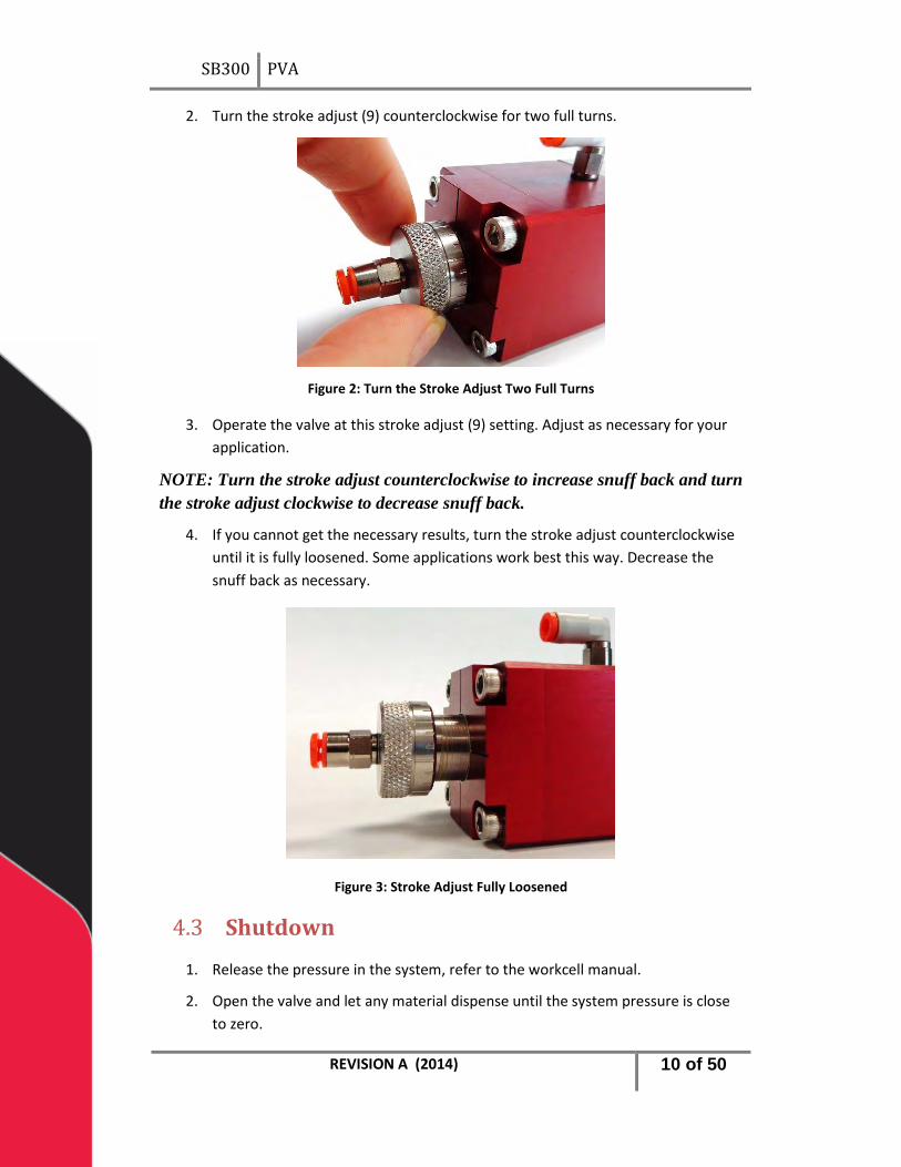
2. Turn the stroke adjust (9) counterclockwise for two full turns.
Figure 2: Turn the Stroke Adjust Two Full Turns
3. Operate the valve at this stroke adjust (9) setting. Adjust as necessary for your application.
NOTE: Turn the stroke adjust counterclockwise to increase snuff back and turn the stroke adjust clockwise to decrease snuff back.
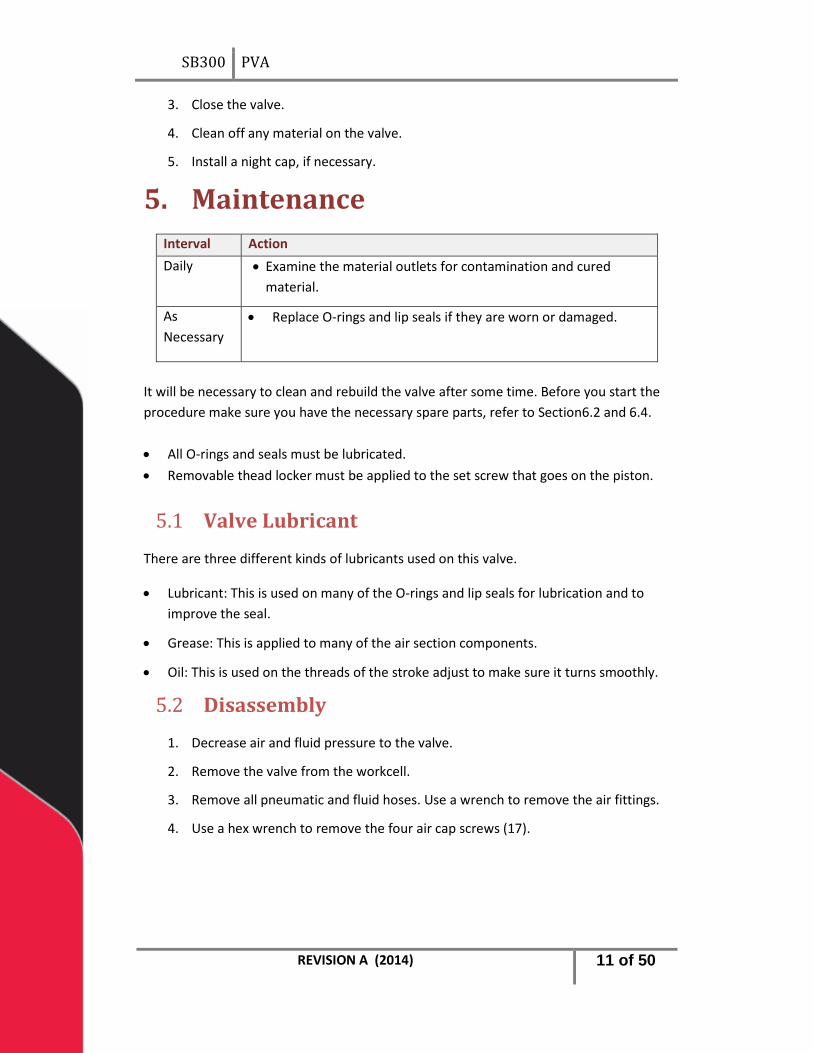
4. If you cannot get the necessary results, turn the stroke adjust counterclockwise until it is fully loosened. Some applications work best this way. Decrease the snuff back as necessary.
Figure 3: Stroke Adjust Fully Loosened
Shutdown 4.3
1. Release the pressure in the system, refer to the workcell manual.
2. Open the valve and let any material dispense until the system pressure is close to zero.
REVISION A (2014) 10 of 50
SB300 PVA
3. Close the valve.
4. Clean off any material on the valve.
5. Install a night cap, if necessary.
Maintenance 5.Interval Action Daily • Examine the material outlets for contamination and cured
material.
As Necessary
• Replace O-rings and lip seals if they are worn or damaged.
It will be necessary to clean and rebuild the valve after some time. Before you start the procedure make sure you have the necessary spare parts, refer to Section6.2 and 6.4. • All O-rings and seals must be lubricated. • Removable thead locker must be applied to the set screw that goes on the piston.
Valve Lubricant 5.1
There are three different kinds of lubricants used on this valve.
• Lubricant: This is used on many of the O-rings and lip seals for lubrication and to improve the seal.
• Grease: This is applied to many of the air section components.
• Oil: This is used on the threads of the stroke adjust to make sure it turns smoothly.
Disassembly 5.2
1. Decrease air and fluid pressure to the valve.
2. Remove the valve from the workcell.
3. Remove all pneumatic and fluid hoses. Use a wrench to remove the air fittings.
4. Use a hex wrench to remove the four air cap screws (17).
REVISION A (2014) 11 of 50

SB300 PVA
Figure 4: Loosen and Remove the Four Air Cap Screws
5. Pull on the air and fluid sections to separate the sections.
Figure 5: Air and Fluid Sections Separated
6. Use a hex wrench to remove the four separation body screws (14).
Figure 6: Remove the Four Screws
7. Remove the separation body (6) from the fluid body (7).
REVISION A (2014) 12 of 50
SB300 PVA
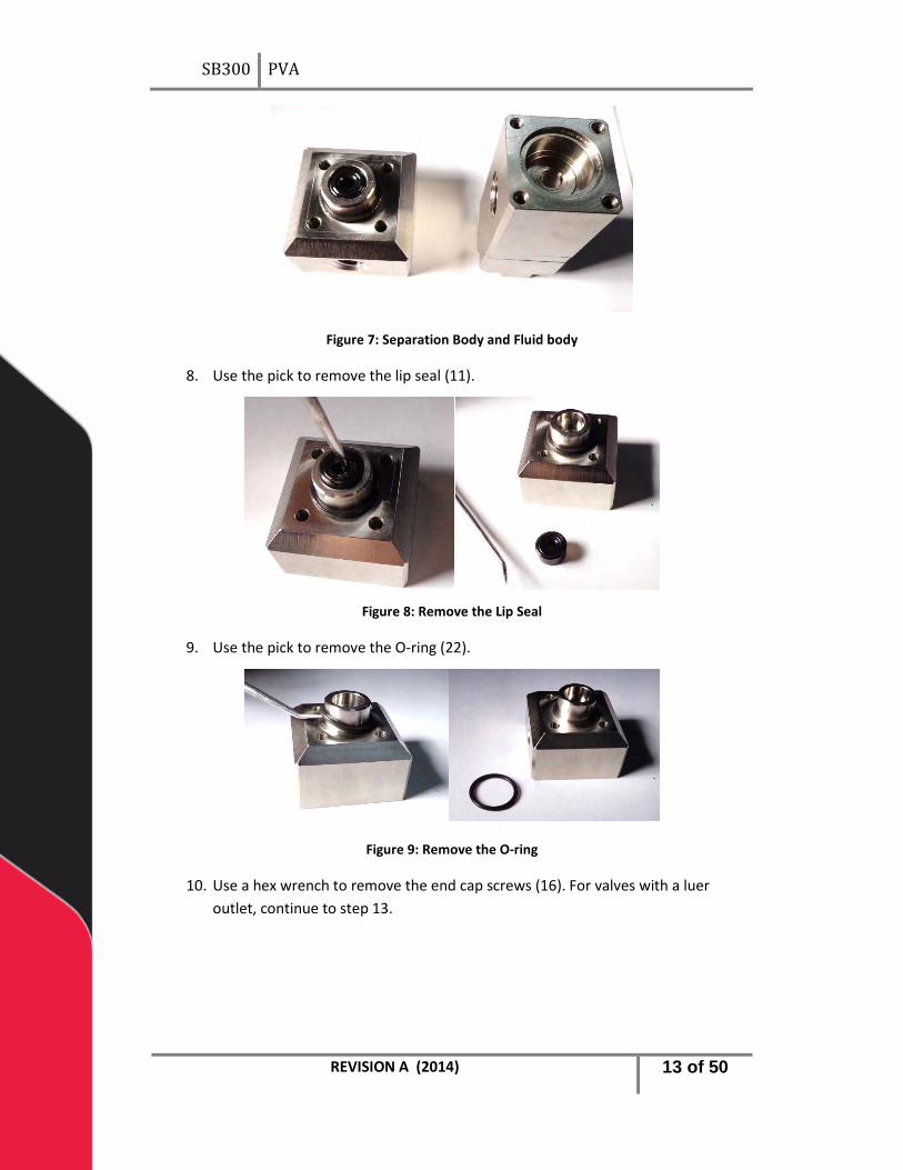
Figure 7: Separation Body and Fluid body
8. Use the pick to remove the lip seal (11).
Figure 8: Remove the Lip Seal
9. Use the pick to remove the O-ring (22).
Figure 9: Remove the O-ring
10. Use a hex wrench to remove the end cap screws (16). For valves with a luer outlet, continue to step 13.
REVISION A (2014) 13 of 50

SB300 PVA
Figure 10: Remove End Cap Screws
11. Separate the end cap (10) from the seal plate (1).
Figure 11: Separate Sections
12. Use a pick to remove the O-ring (21).
Figure 12: Remove the End Cap O-ring
Continue to step 19 for valves with the 1/4” NPT end fitting.
For For valves with a luer outlet:
NOTE: part numbers for steps 13-18 refer to drawing number 112-07384.
13. Use a hex wrench to remove the end cap screws (16).
REVISION A (2014) 14 of 50

SB300 PVA
Figure 13: Remove the Screws from the End Cap
14. Separate the end cap (3) from the seal plate (1).
Figure 14: Separate the End Cap from the Seal Plate
15. Use a wrench to loosen and remove the luer adaptor (20).
Figure 15: Remove the Luer Adaptor
16. Use a pick to remove the washer (19) from the end cap (3).
REVISION A (2014) 15 of 50
SB300 PVA
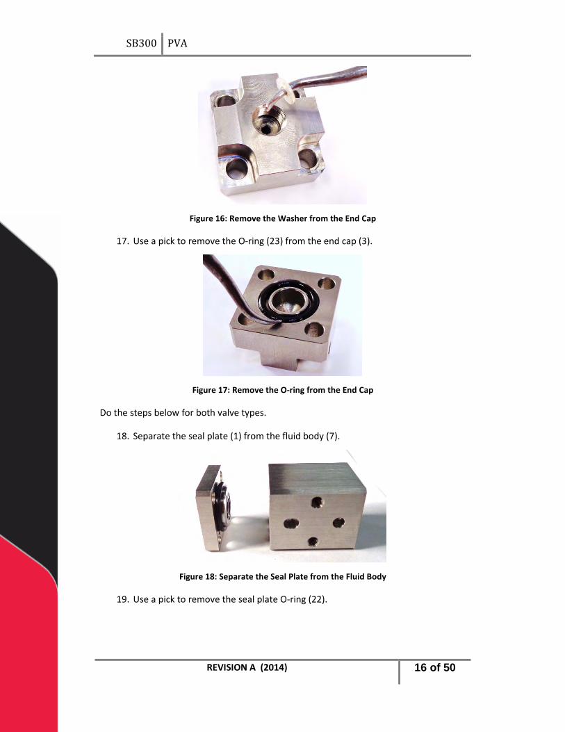
Figure 16: Remove the Washer from the End Cap
17. Use a pick to remove the O-ring (23) from the end cap (3).
Figure 17: Remove the O-ring from the End Cap
Do the steps below for both valve types.
18. Separate the seal plate (1) from the fluid body (7).
Figure 18: Separate the Seal Plate from the Fluid Body
19. Use a pick to remove the seal plate O-ring (22).
REVISION A (2014) 16 of 50

SB300 PVA
Figure 19: Remove the O-ring
20. Use a pick to remove the lip seal (12) from the seal plate (1).
Figure 20: Remove the Lip Seal
21. Use a pick to remove both of the washers (2) from the fluid body (7).
Figure 21: Washers in the Fluid Body
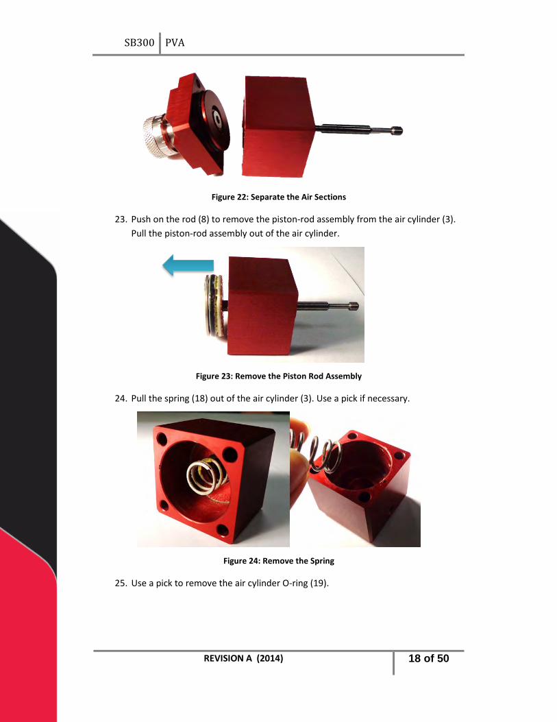
22. Separate the air cap (5) from the air cylinder (3).
REVISION A (2014) 17 of 50
SB300 PVA
Figure 22: Separate the Air Sections
23. Push on the rod (8) to remove the piston-rod assembly from the air cylinder (3). Pull the piston-rod assembly out of the air cylinder.
Figure 23: Remove the Piston Rod Assembly
24. Pull the spring (18) out of the air cylinder (3). Use a pick if necessary.
Figure 24: Remove the Spring
25. Use a pick to remove the air cylinder O-ring (19).
REVISION A (2014) 18 of 50

SB300 PVA
Figure 25: Remove the Air Cylinder O-ring
26. Use a pick to remove the piston O-ring (24).
Figure 26: Remove the Piston O-ring
27. Use a hex wrench to remove the set screw (15) in the piston (4). Hold the flat section on rod (8) with a wrench and turn the set screw until it is loose.
Figure 27: Disassemble the Piston-Rod Assembly
28. Disassemble the piston-rod assembly.
REVISION A (2014) 19 of 50

SB300 PVA
Figure 28: Disassembled Piston-Rod Assembly
29. Use a pick to remove the air cap O-ring (23).
This is the end of the normal disassembly procedure. If it is necessary to disassemble the air cap (5) and stroke adjust (9), do the steps below.
30. Turn the stroke adjust (9) so that the threads can be seen at the bottom of the air cap (5).
31. Use snap ring pliers to remove the snap ring (13) from the stroke adjust (9).
Figure 29: Snap Ring Removed
REVISION A (2014) 20 of 50
SB300 PVA
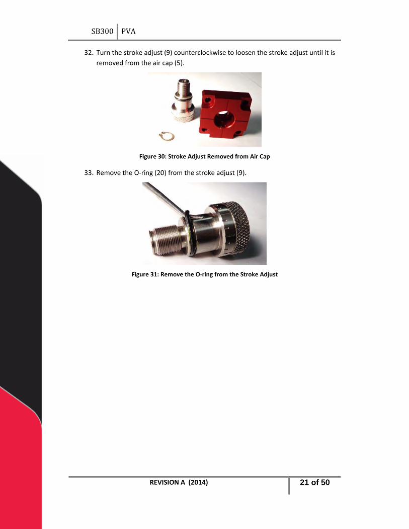
32. Turn the stroke adjust (9) counterclockwise to loosen the stroke adjust until it is removed from the air cap (5).
Figure 30: Stroke Adjust Removed from Air Cap
33. Remove the O-ring (20) from the stroke adjust (9).
Figure 31: Remove the O-ring from the Stroke Adjust
REVISION A (2014) 21 of 50
SB300 PVA
Clean the Valve Components 5.3
Use a compatible solvent to clean the valve components. All components should be cleaned and there should be no material on valve components.
1. Examine and clean all of the O-rings (19, 20, 21, 22, 23, 24).
2. If there is any wear or damage, replace the O-ring.
Figure 32: Examine O-rings
3. Examine and clean the lip seals (11, 12).
4. It they are damaged or show wear, replace the lip seals.
Figure 33: Examine Lip Seals
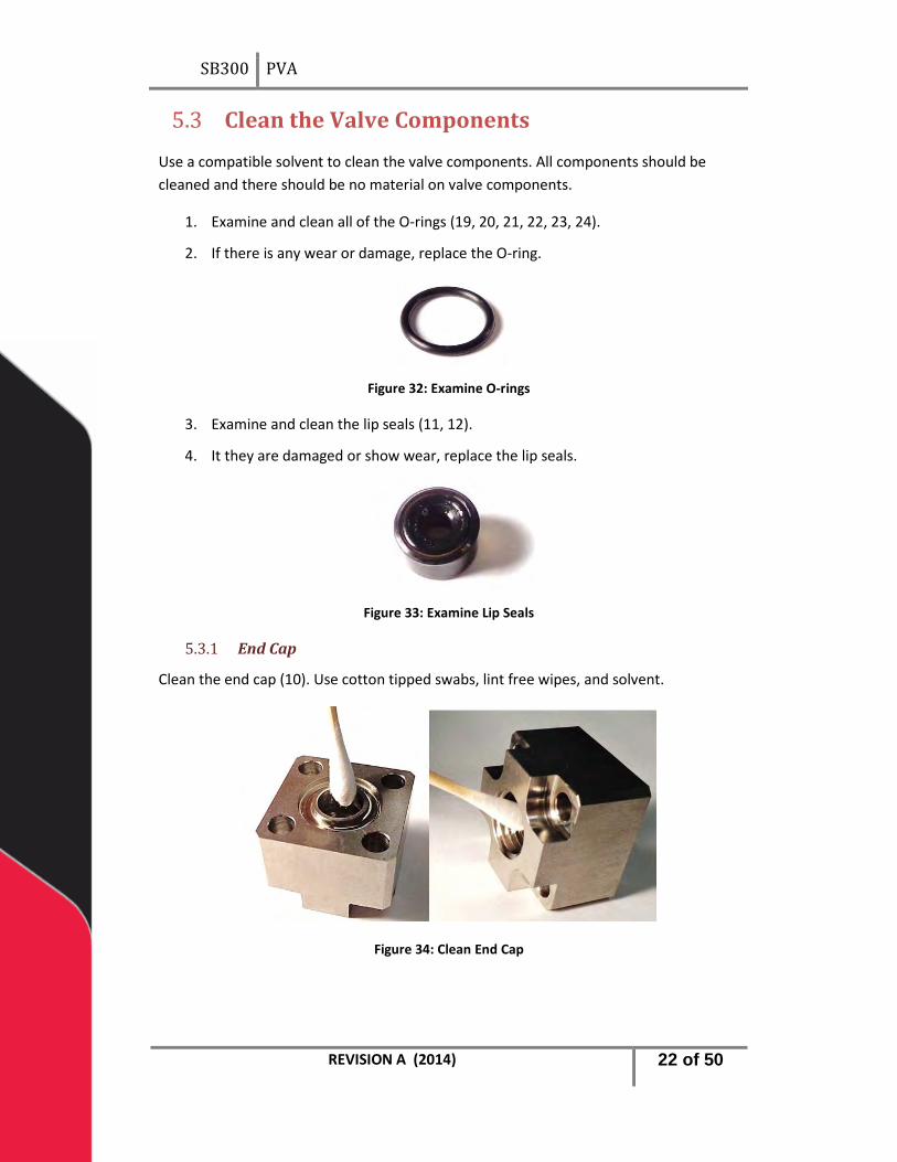
End Cap 5.3.1
Clean the end cap (10). Use cotton tipped swabs, lint free wipes, and solvent.
Figure 34: Clean End Cap
REVISION A (2014) 22 of 50

SB300 PVA
Fluid Body 5.3.2
Clean the fluid body (7). Use cotton tipped swabs, lint free wipes, and solvent.
Figure 35: Clean the Fluid Body
Separation Body 5.3.3
Clean the separation body (6). Use cotton tipped swabs, lint free wipes, and solvent.
Figure 36: Clean the Separation Body
Air Cylinder 5.3.4
Clean the Air Cylinder (3). Use cotton tipped swabs, lint free wipes, and solvent.
Figure 37: Air Cylinder
REVISION A (2014) 23 of 50
SB300 PVA
Air Cap 5.3.5
Clean the Air Cap (5). Use cotton tipped swabs, lint free wipes, and solvent.
Figure 38: Clean the Air Cap
Assemble the Valve 5.4
Do the steps below to assemble the valve after it has been cleaned.
If you disassembled the air cap (5) and stroke adjust (9), put it together again.
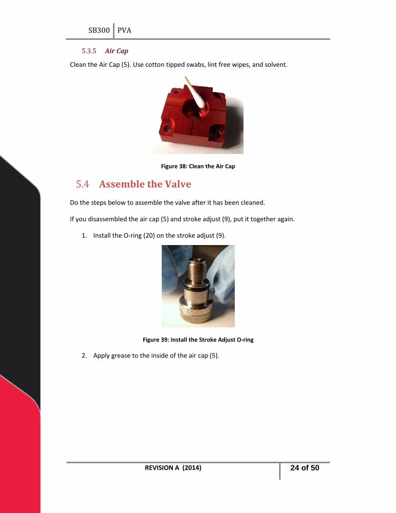
1. Install the O-ring (20) on the stroke adjust (9).
Figure 39: Install the Stroke Adjust O-ring
2. Apply grease to the inside of the air cap (5).
REVISION A (2014) 24 of 50

SB300 PVA
Figure 40: Apply Grease to the Air Cap
3. Put a small amount of oil on the threads of the stroke adjust (9).
Figure 41: Apply Oil to the Stroke Adjust Threads
4. Apply grease to the stroke adjust O-ring (20).
Figure 42: Apply Grease to the O-ring
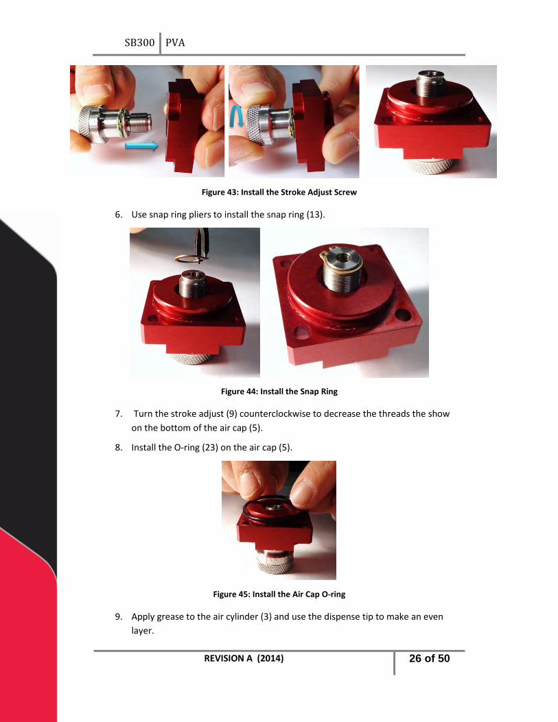
5. Install the stroke adjust (9) into the air cap. Turn the stroke adjust clockwise until it is engaged and the threads can be seen coming through the air cap (5).
REVISION A (2014) 25 of 50
SB300 PVA
Figure 43: Install the Stroke Adjust Screw
6. Use snap ring pliers to install the snap ring (13).
Figure 44: Install the Snap Ring
7. Turn the stroke adjust (9) counterclockwise to decrease the threads the show on the bottom of the air cap (5).
8. Install the O-ring (23) on the air cap (5).
Figure 45: Install the Air Cap O-ring
9. Apply grease to the air cylinder (3) and use the dispense tip to make an even layer.
REVISION A (2014) 26 of 50

SB300 PVA
Figure 46: Apply Grease to the Air Cylinder
10. Get the piston (4), rod (8), set screw (15), and O-ring (24).
Figure 47: Piston-Rod Assembly Components
11. Apply removable thread locker to the set screw (15).
Figure 48: Apply Removable Thread Locker
12. Put the rod (8) on the side of the piston (4) with the groove in it.
REVISION A (2014) 27 of 50
SB300 PVA
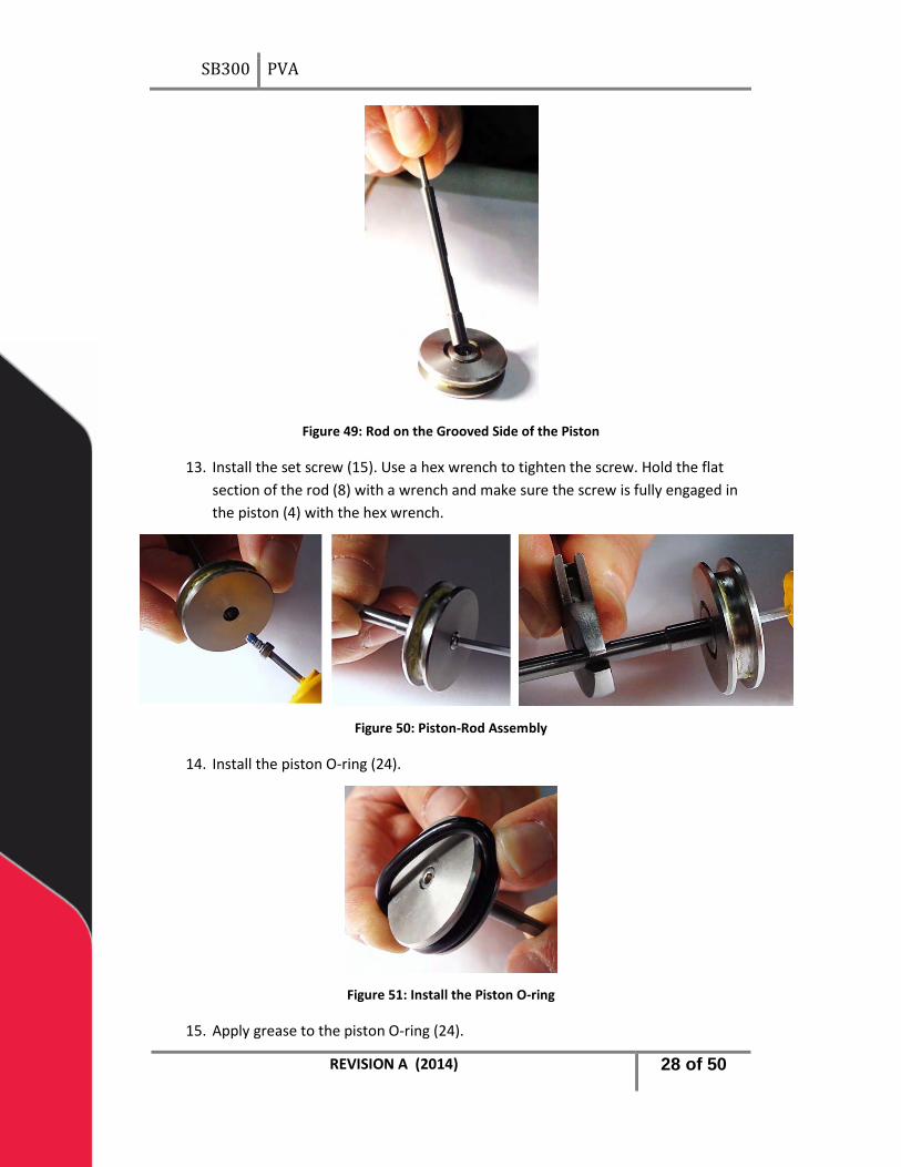
Figure 49: Rod on the Grooved Side of the Piston
13. Install the set screw (15). Use a hex wrench to tighten the screw. Hold the flat section of the rod (8) with a wrench and make sure the screw is fully engaged in the piston (4) with the hex wrench.
Figure 50: Piston-Rod Assembly
14. Install the piston O-ring (24).
Figure 51: Install the Piston O-ring
15. Apply grease to the piston O-ring (24).
REVISION A (2014) 28 of 50
SB300 PVA
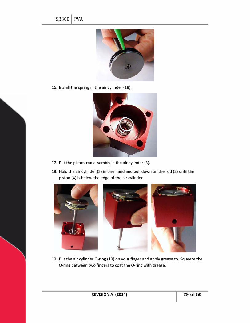
16. Install the spring in the air cylinder (18).
17. Put the piston-rod assembly in the air cylinder (3).
18. Hold the air cylinder (3) in one hand and pull down on the rod (8) until the piston (4) is below the edge of the air cylinder.
19. Put the air cylinder O-ring (19) on your finger and apply grease to. Squeeze the O-ring between two fingers to coat the O-ring with grease.
REVISION A (2014) 29 of 50
SB300 PVA
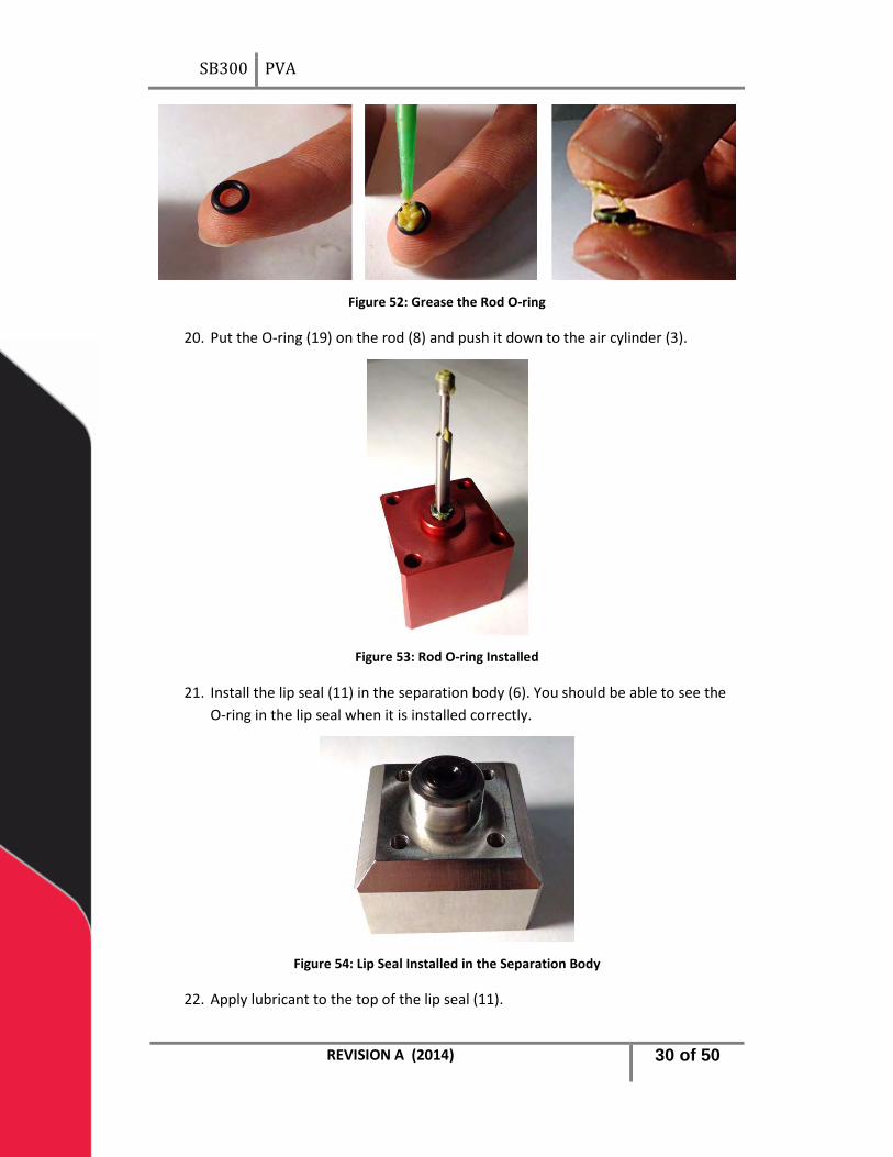
Figure 52: Grease the Rod O-ring
20. Put the O-ring (19) on the rod (8) and push it down to the air cylinder (3).
Figure 53: Rod O-ring Installed
21. Install the lip seal (11) in the separation body (6). You should be able to see the O-ring in the lip seal when it is installed correctly.
Figure 54: Lip Seal Installed in the Separation Body
22. Apply lubricant to the top of the lip seal (11).
REVISION A (2014) 30 of 50

SB300 PVA
Figure 55: Apply Lubricant to the Top of the Lip Seal
23. Apply a small amount of lubricant to the lowest edge inside the fluid body. Do this for both sides
Figure 56: Apply Lubricant to the Fluid Body
24. Install the washer (2) in the fluid body. Do this for both sides.
Figure 57: Install the Washers in the Fluid Body
REVISION A (2014) 31 of 50
SB300 PVA
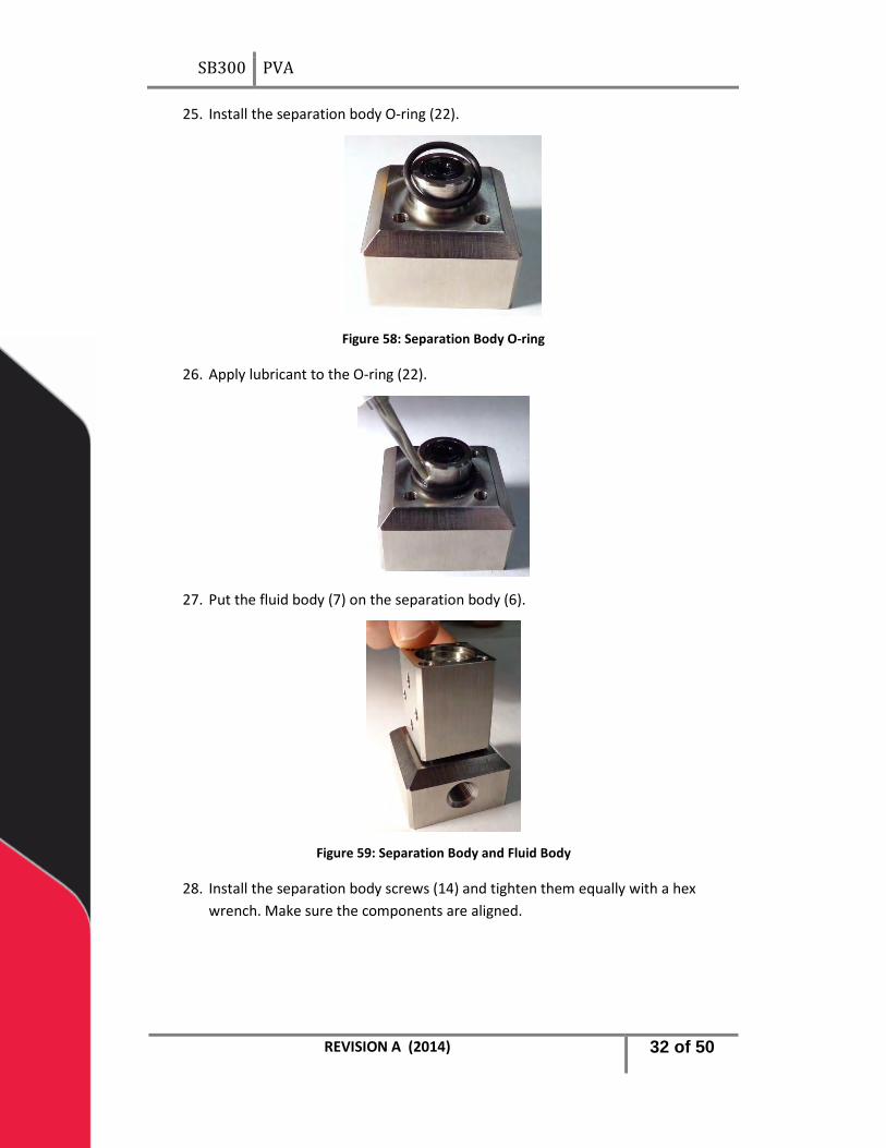
25. Install the separation body O-ring (22).
Figure 58: Separation Body O-ring
26. Apply lubricant to the O-ring (22).
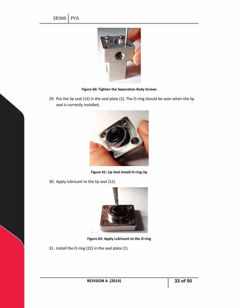
27. Put the fluid body (7) on the separation body (6).
Figure 59: Separation Body and Fluid Body
28. Install the separation body screws (14) and tighten them equally with a hex wrench. Make sure the components are aligned.
REVISION A (2014) 32 of 50
SB300 PVA
Figure 60: Tighten the Separation Body Screws
29. Put the lip seal (12) in the seal plate (1). The O-ring should be seen when the lip seal is correctly installed.
Figure 61: Lip Seal Install O-ring Up
30. Apply lubricant to the lip seal (12).
Figure 62: Apply Lubricant to the O-ring
31. Install the O-ring (22) in the seal plate (1).
REVISION A (2014) 33 of 50

SB300 PVA
Figure 63: Install the Seal Plate O-ring
32. Apply lubricant to the O-ring (22) in the seal plate (1).
Figure 64: Apply Lubricant to the Seal Plate O-ring
33. Install the seal plate (1) on top of the fluid body (7).
Figure 65: Install the Seal Plate
34. Apply lubricant to the O-ring groove in the end cap (10).
REVISION A (2014) 34 of 50

SB300 PVA
Figure 66: Apply Lubricant to the O-ring Groove
35. Install the O-ring (21) in the end cap (10).
Figure 67: End Cap O-ring Installed
36. Apply lubricant to the end cap O-ring (21).
Figure 68: Apply Lubricant to the End Cap O-ring
37. Install the end cap (10) on top of the seal plate (1).
REVISION A (2014) 35 of 50
SB300 PVA
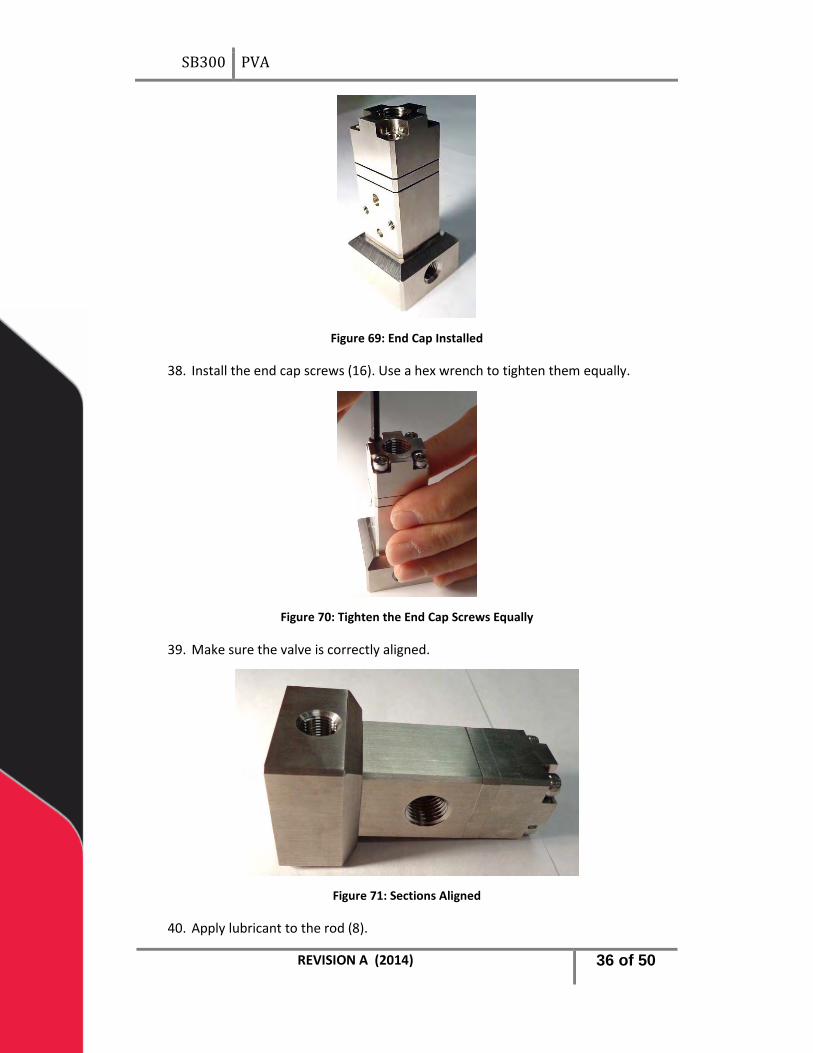
Figure 69: End Cap Installed
38. Install the end cap screws (16). Use a hex wrench to tighten them equally.
Figure 70: Tighten the End Cap Screws Equally
39. Make sure the valve is correctly aligned.
Figure 71: Sections Aligned
40. Apply lubricant to the rod (8).
REVISION A (2014) 36 of 50
SB300 PVA
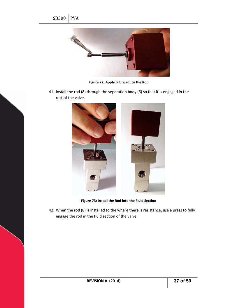
Figure 72: Apply Lubricant to the Rod
41. Install the rod (8) through the separation body (6) so that it is engaged in the rest of the valve.
Figure 73: Install the Rod into the Fluid Section
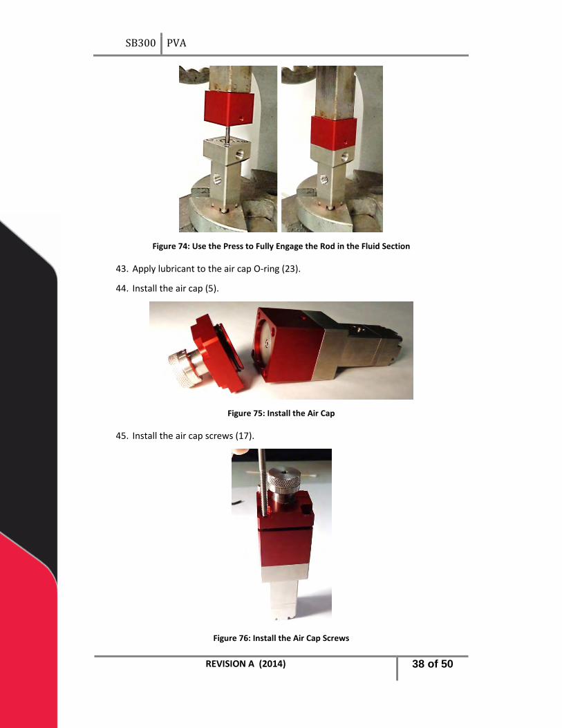
42. When the rod (8) is installed to the where there is resistance, use a press to fully engage the rod in the fluid section of the valve.
REVISION A (2014) 37 of 50
SB300 PVA
Figure 74: Use the Press to Fully Engage the Rod in the Fluid Section
43. Apply lubricant to the air cap O-ring (23).
44. Install the air cap (5).
Figure 75: Install the Air Cap
45. Install the air cap screws (17).
Figure 76: Install the Air Cap Screws
REVISION A (2014) 38 of 50
SB300 PVA
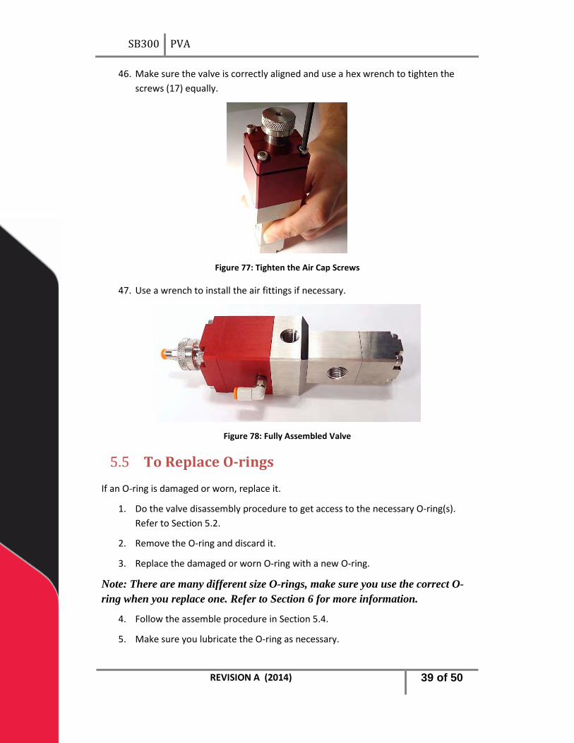
46. Make sure the valve is correctly aligned and use a hex wrench to tighten the screws (17) equally.
Figure 77: Tighten the Air Cap Screws
47. Use a wrench to install the air fittings if necessary.
Figure 78: Fully Assembled Valve
To Replace O-rings 5.5
If an O-ring is damaged or worn, replace it.
1. Do the valve disassembly procedure to get access to the necessary O-ring(s). Refer to Section 5.2.
2. Remove the O-ring and discard it.
3. Replace the damaged or worn O-ring with a new O-ring.
Note: There are many different size O-rings, make sure you use the correct O-ring when you replace one. Refer to Section 6 for more information.
4. Follow the assemble procedure in Section 5.4.
5. Make sure you lubricate the O-ring as necessary.
REVISION A (2014) 39 of 50

SB300 PVA
To Replace Lip Seals 5.6
If a lip seal is damaged or worn, replace it.
1. Do the valve disassembly procedure to get access to the necessary lip seal(s). Refer to Section 5.2.
2. Use the hook and pick set to remove the lip seal and discard it.
3. Replace the damaged or worn lip seal with the correct, new lip seal.
4. Follow the assemble procedure in Section 5.4.
5. Make sure you lubricate the lip seals as necessary.
REVISION A (2014) 40 of 50
SB300 PVA
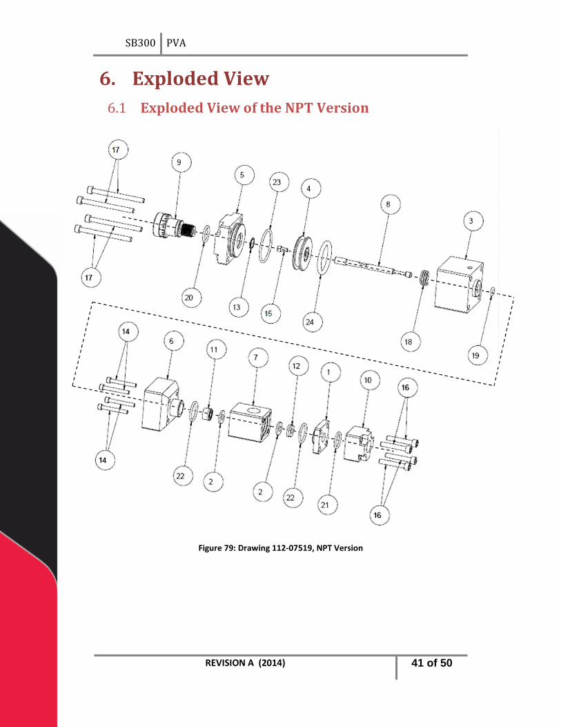
Exploded View 6. Exploded View of the NPT Version 6.1
Figure 79: Drawing 112-07519, NPT Version
REVISION A (2014) 41 of 50
SB300 PVA
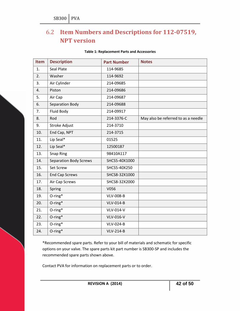
Item Numbers and Descriptions for 112-07519, 6.2NPT version
Table 1: Replacement Parts and Accessories
Item Description Part Number Notes 1. Seal Plate 114-9685
2. Washer 114-9692
3. Air Cylinder 214-09685
4. Piston 214-09686
5. Air Cap 214-09687
6. Separation Body 214-09688
7. Fluid Body 214-09917
8. Rod 214-3376-C May also be referred to as a needle
9. Stroke Adjust 214-3710
10. End Cap, NPT 214-3715
11. Lip Seal* 01525
12. Lip Seal* 12500187
13. Snap Ring 98410A117
14. Separation Body Screws SHCS5-40X1000
15. Set Screw SHCS5-40X250
16. End Cap Screws SHCS8-32X1000
17. Air Cap Screws SHCS8-32X2000
18. Spring V056
19. O-ring* VLV-008-B
20. O-ring* VLV-014-B
21. O-ring* VLV-014-V
22. O-ring* VLV-016-V
23. O-ring* VLV-024-B
24. O-ring* VLV-214-B
*Recommended spare parts. Refer to your bill of materials and schematic for specific options on your valve. The spare parts kit part number is SB300-SP and includes the recommended spare parts shown above.
Contact PVA for information on replacement parts or to order.
REVISION A (2014) 42 of 50
SB300 PVA
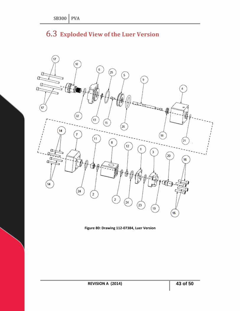
Exploded View of the Luer Version 6.3
Figure 80: Drawing 112-07384, Luer Version
REVISION A (2014) 43 of 50

SB300 PVA
Item Numbers and Descriptions for 112-07384, 6.4Luer version
Table 2: Replacement Parts and Accessories
Item Description Part Number Notes 1. Seal Plate 114-9685
2. Washer 114-9692
3. End Cap 114-9700
4. Air Cylinder 214-09685
5. Piston 214-09686
6. Air Cap 214-09687
7. Separation Body 214-09688
8. Fluid Body 214-09917
9. Rod 214-3376-C May also be referred to as a needle
10. Stroke Adjust 214-3710
11. Lip Seal* 01525
12. Lip Seal* 12500187
13. Snap Ring 98410A117
14. Separation Body Screws SHCS5-40X1000
15. Set Screw SHCS5-40X250
16. End Cap Screws SHCS8-32X0750
17. Air Cap Screws SHCS8-32X2000
18. Spring V056
19. Washer* V125
20. Luer Adaptor V300
21. O-ring* VLV-008-B
22. O-ring* VLV-014-B
23. O-ring* VLV-014-V
24. O-ring* VLV-016-V
25. O-ring* VLV-024-B
26. O-ring* VLV-214-B
*Recommended spare parts. Refer to your bill of materials and schematic for specific options on your valve. The spare parts kit part number is SB300-SP and includes the recommended spare parts shown above.
Contact PVA for information on replacement parts or to order. REVISION A (2014) 44 of 50
SB300 PVA
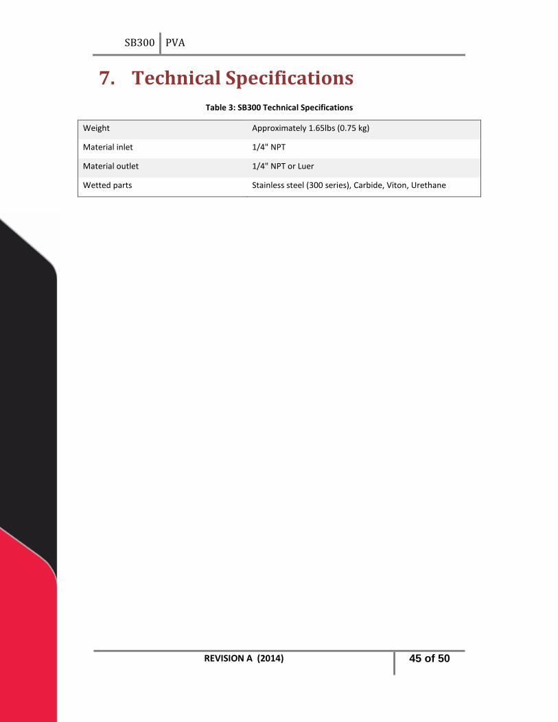
Technical Specifications 7.Table 3: SB300 Technical Specifications
Weight Approximately 1.65lbs (0.75 kg)
Material inlet 1/4" NPT
Material outlet 1/4" NPT or Luer
Wetted parts Stainless steel (300 series), Carbide, Viton, Urethane
REVISION A (2014) 45 of 50

SB300 PVA
Troubleshooting 8.Troubleshooting Problem
Possible Cause Corrective Action
Valve does not cycle
• Air pressure to air section is too low
• Material is cured in the valve
• O-rings were not lubricated when valve was assembled
• Increase air pressure to 60-100 psi
• Disassemble and clean the valve
• Disassemble the valve, lubricate the O-rings and seals and reassemble
Valve does not dispense material
• The fluid pressure is too low
• Material is cured in the fluid section
• Increase the fluid pressure
• Disassemble and clean the valve
Valve leaks from the tip
• Stroke adjust is down too far
• Rod or lip seals are worn
• Air bubble trapped in fluid section
• Turn stroke adjust counterclockwise
• Replace parts as necessary
• Flip valve upside down and cycle until all air is removed
Valve leaks from mid-section
• Lip seal is worn • Replace lip seal
There are air bubbles in fluid
• Valve not correctly bled
• Stroke adjust is up too far
• Problem with the Fluid delivery system
• Do the complete bled procedure, flip valve upside down and cycle until the air is removed if necessary
• Turn the stroke adjust clockwise
• Diagnose and repair
REVISION A (2014) 46 of 50
SB300 PVA
Notes 9.
REVISION A (2014) 47 of 50

SB300 PVA
Warranty 10.PVA Warranty Policy
PVA warrants the enclosed product against defects in material or workmanship on all components for one year from the date of shipment.
The warranty does not extend to components damaged due to misuse, negligence, or installation and operation that are not in accordance with the recommended factory instructions. Unauthorized repair or modification of the enclosed product, and/or the use of spare parts not directly obtained from PVA (or from factory authorized dealers) will void all warranties.
All PVA warranties extend only to the original purchaser. Third party warranty claims will not be honored at any time.
Prior to returning a product for a warranty claim, a return authorization must be obtained from PVA’s customer service department. Authorization will be issued either via the telephone, facsimile, or in writing upon your request.
To qualify as a valid warranty claim, the defective product must be returned to the factory during the warranty period. Upon return, PVA will repair (or replace) all components found to be defective in material or workmanship.
(Retain this for your records)
Product Information:
PRODUCT: ______________________________
SERIAL NUMBER: ______________________________
DATE OF PURCHASE: ______________________________
REVISION A (2014) 48 of 50

SB300 PVA
Table of Figures 11.Figure 1: Valve Components ............................................................................................... 8 Figure 2: Turn the Stroke Adjust Two Full Turns............................................................... 10 Figure 3: Stroke Adjust Fully Loosened ............................................................................. 10 Figure 4: Loosen and Remove the Four Air Cap Screws ................................................... 12 Figure 5: Air and Fluid Sections Separated ....................................................................... 12 Figure 6: Remove the Four Screws ................................................................................... 12 Figure 7: Separation Body and Fluid body ........................................................................ 13 Figure 8: Remove the Lip Seal ........................................................................................... 13 Figure 9: Remove the O-ring ............................................................................................. 13 Figure 10: Remove End Cap Screws .................................................................................. 14 Figure 11: Separate Sections ............................................................................................. 14 Figure 12: Remove the End Cap O-ring ............................................................................. 14 Figure 13: Remove the Screws from the End Cap............................................................. 15 Figure 14: Separate the End Cap from the Seal Plate ....................................................... 15 Figure 15: Remove the Luer Adaptor ................................................................................ 15 Figure 16: Remove the Washer from the End Cap ........................................................... 16 Figure 17: Remove the O-ring from the End Cap .............................................................. 16 Figure 18: Separate the Seal Plate from the Fluid Body ................................................... 16 Figure 19: Remove the O-ring ........................................................................................... 17 Figure 20: Remove the Lip Seal ......................................................................................... 17 Figure 21: Washers in the Fluid Body ............................................................................... 17 Figure 22: Separate the Air Sections ................................................................................. 18 Figure 23: Remove the Piston Rod Assembly ................................................................... 18 Figure 24: Remove the Spring ........................................................................................... 18 Figure 25: Remove the Air Cylinder O-ring ....................................................................... 19 Figure 26: Remove the Piston O-ring ................................................................................ 19 Figure 27: Disassemble the Piston-Rod Assembly ............................................................ 19 Figure 28: Disassembled Piston-Rod Assembly ................................................................ 20 Figure 29: Snap Ring Removed ......................................................................................... 20 Figure 30: Stroke Adjust Removed from Air Cap .............................................................. 21 Figure 31: Remove the O-ring from the Stroke Adjust ..................................................... 21 Figure 32: Examine O-rings ............................................................................................... 22 Figure 33: Examine Lip Seals ............................................................................................. 22 Figure 34: Clean End Cap .................................................................................................. 22 Figure 35: Clean the Fluid Body ........................................................................................ 23 Figure 36: Clean the Separation Body............................................................................... 23 Figure 37: Air Cylinder ....................................................................................................... 23 Figure 38: Clean the Air Cap.............................................................................................. 24 Figure 39: Install the Stroke Adjust O-ring ........................................................................ 24
REVISION A (2014) 49 of 50

SB300 PVA
Figure 40: Apply Grease to the Air Cap ............................................................................. 25 Figure 41: Apply Oil to the Stroke Adjust Threads ............................................................ 25 Figure 42: Apply Grease to the O-ring .............................................................................. 25 Figure 43: Install the Stroke Adjust Screw ........................................................................ 26 Figure 44: Install the Snap Ring ......................................................................................... 26 Figure 45: Install the Air Cap O-ring .................................................................................. 26 Figure 46: Apply Grease to the Air Cylinder ...................................................................... 27 Figure 47: Piston-Rod Assembly Components .................................................................. 27 Figure 48: Apply Removable Thread Locker ..................................................................... 27 Figure 49: Rod on the Grooved Side of the Piston............................................................ 28 Figure 50: Piston-Rod Assembly ....................................................................................... 28 Figure 51: Install the Piston O-ring ................................................................................... 28 Figure 52: Grease the Rod O-ring ..................................................................................... 30 Figure 53: Rod O-ring Installed ......................................................................................... 30 Figure 54: Lip Seal Installed in the Separation Body ......................................................... 30 Figure 55: Apply Lubricant to the Top of the Lip Seal ....................................................... 31 Figure 56: Apply Lubricant to the Fluid Body .................................................................... 31 Figure 57: Install the Washers in the Fluid Body .............................................................. 31 Figure 58: Separation Body O-ring .................................................................................... 32 Figure 59: Separation Body and Fluid Body ...................................................................... 32 Figure 60: Tighten the Separation Body Screws ............................................................... 33 Figure 61: Lip Seal Install O-ring Up .................................................................................. 33 Figure 62: Apply Lubricant to the O-ring .......................................................................... 33 Figure 63: Install the Seal Plate O-ring .............................................................................. 34 Figure 64: Apply Lubricant to the Seal Plate O-ring .......................................................... 34 Figure 65: Install the Seal Plate ......................................................................................... 34 Figure 66: Apply Lubricant to the O-ring Groove .............................................................. 35 Figure 67: End Cap O-ring Installed................................................................................... 35 Figure 68: Apply Lubricant to the End Cap O-ring ............................................................ 35 Figure 69: End Cap Installed.............................................................................................. 36 Figure 70: Tighten the End Cap Screws Equally ................................................................ 36 Figure 71: Sections Aligned ............................................................................................... 36 Figure 72: Apply Lubricant to the Rod .............................................................................. 37 Figure 73: Install the Rod into the Fluid Section ............................................................... 37 Figure 74: Use the Press to Fully Engage the Rod in the Fluid Section ............................. 38 Figure 75: Install the Air Cap ............................................................................................. 38 Figure 76: Install the Air Cap Screws ................................................................................. 38 Figure 77: Tighten the Air Cap Screws .............................................................................. 39 Figure 78: Fully Assembled Valve ..................................................................................... 39 Figure 79: Drawing 112-07519, NPT Version .................................................................... 41 Figure 80: Drawing 112-07384, Luer Version ................................................................... 43
REVISION A (2014) 50 of 50