Embed Size (px)
Citation preview

Ball Valves
One piece body construc! on, Full / Reduced Bore Valve
KITZ CORPORATION OF EUROPE S.A.
T h e r e l i a b l e b r a n d
HB-Class 800/900/1500/2500SB-Class 800

2
Ball ValvesFloa� ng Ball design
Class 800 Carbon Steel / Stainless Steel Ball Valves (SB-80) 3
Class 800 Carbon Steel / Stainless Steel Ball Valves (HB) 4
Class 900 Carbon Steel / Stainless Steel Ball Valves (HB 6
Class 1500 Carbon Steel / Stainless Steel Ball Valves (HB) 8
Class 2500 Carbon Steel / Stainless Steel Ball Valves (HB) 10
Contents
KITZ Corpora! on Headquarter, Chiba, Japan KITZ Corpora! on of Europe, S.A., Barcelona Plant, Spain
All products introduced in this cataloge are covered by ISO 9001 certification awarded KITZ Corporation of Europe, S.A.

Ball Valves, Floa� ng Ball Design
3
SB-80 - Class 800 Carbon Steel / Stainless Steel Ball Valves
Reduced Bore Valve, 1 piece body construc� on
Features
• An! sta! c device
• Blowout-proof stem
• High performance PTFE ball seats
Standards
• Ball valves are designed according to EN 1983/B16.34
Connec� ons
• NPT thread: ANSI B1.20.1
• BSP thread: ISO228
• BW (only one side): Nipple Sch 40-80
(Ansi B16.25), Screwed (other side)
• SW : ASME B16.5
CLASS 800
NPS PortDimensions
L H P
1/4”
9.5 60 53
120
3/8”
1/2”
3/4” 12,5 70 56
1” 17 80 58
11/2” 25 100 97150
2” 32 110 102
No. Parts Carbon Steel Stainless Steel
1 Body ASTM A105ASTM A479/A182
Gr. 316L
3 Insert ASTM A105 ASTM A479 316
5 An! sta! c Stem ASTM A479 Type 316
6 Gland ASTM A479 Type 316
8 Stop Pin Steel DIN 267/11 A2-70
11 Spring washer Blued steel 304CSP
12 Nut DIN267/4 C 8 blued DIN 267/11 A2-70
21 Ball ASTM A479 Type 316
22 Ball seat PTFE
25 Gland Packing Graphite
26 Stem Seal PTFE + 25% Graphite
30 Handle Steel coated
37 Stop washer Stainless Steel
40 Stem O’ring All gas and ≥ 11/2” : FKM
Construc� on and Standard Materials
BSP
NPT
BSP/NPT
END CONNECTIONS
All part numbers are corresponding with those shown in valve assembly drawings.
Dimensions: mm
Dimensions: mm

Ball Valves, Floa� ng Ball Design
4
HB - Class 800 Carbon Steel / Stainless Steel Ball Valves
Full or reduced Bore Valve, 1 piece body construc� on
Features
• An! sta! c device
• Blowout-proof stem
• Fire test cer! fi ca! on
• High performance PTFE ball seats
Standards
• Ball valves design according to EN 1983/B16.34
• FSM according to API 607 - ISO 10497
Connec� ons
• NPT thread: ANSI B1.20.1
• BSP thread: ISO228
• SW: Ansi B16.5
• BW: SW+Nipples Sch 40-80 (Ansi B16.25)
Page 5 for Construc! on and Materials
CLASS 800
NPSPort
Dimensions
L L1 L2 H PSW sch A
RB FB RB FB
- 1/4”
12,5 90
240
400
85
150
- 14,1
- 3/8” - 17,7
3/4” 1/2” 27,4 21,8
1” 3/4” 19 110 90 34,1 27,4
- 1” 25 120 100 - 34,1
11/2” - 32 130
260
105200
49 -
2” 11/2” 38 150 110 61 49
- 2” 51 180 116 350 - 61
Execu! on BW = SW + Nipple
NPS ØMSch 10S Sch 40S Sch 80 Sch 160
ØN ØR ØN ØR ØN ØR ØN ØR
½” 21,3 - 17,1 - 15,8 - 13,9 15,0 11,8
¾” 26,7 - 22,5 - 21,0 - 18,9 18,8 15,6
1” 33,4 31,1 27,9 29,8 26,6 27,5 24,3 23,9 20,7
1½” 48,3 46,0 42,8 44,1 40,9 41,3 38,1 37,2 34,0
2” 60,3 58,0 54,8 55,7 52,5 52,4 49,2 46,1 42,9
Cod. CS Standard Special
Cod. SS Special Standard
Dimensions: mm
Dimensions: mm

Ball Valves, Floa� ng Ball Design
5
HB Class 800 - Construc� on and Standard Materials
No. Parts Carbon Steel Stainless Steel
1 Body ASTM A105 ASTM A479 316L
4 Body Connector ASTM A105 ASTM A479 316L
5 An� sta� c Stem ASTM A479 Type 316
6 Gland ASTM A479 Type 316
8 Stop Pin Steel DIN 267/11 A2-70
9 Stop plate (DN>1”) Steel
11 Spring washer Blued steel 304CSP
12 Nut DIN 267/3 C 8 .8 blued DIN 267/11 A2-70
21 BallDN ≤ 1”: ASTM A479 Type 316
DN ≥ 1½”: DIN 1.4408 (CF8M)
22 Ball seat PTFE
25 Gland Packing Graphite
26 Stem SealDN ≤ 1”: PTFE + 25% Graphite
DN ≥ 1½”: PTFE
28 Nipple ASTM A106 gr. B ASTM A312 Type 316L
30 HandleDN ≤ 1”: Steel coated
DN ≥ 1½”: GGG40
40 Stem O’ring FKM
END CONNECTIONS
BSP
NPT
SW Sch
SW mm.
BW:
SW+Nipple
BSP/NPT
ØA
All part numbers are corresponding with those shown in valve assembly drawings.

Ball Valves, Floa� ng Ball Design
6
HB - Class 900 Carbon Steel / Stainless Steel Ball Valves
Full or reduced Bore Valve, 1 piece body construc� on
Features
• An! sta! c device
• Blowout-proof stem
• Fire test cer! fi ca! on
• High performance PCTFE ball seats
Standards
• Ball valves design according to BS EN 12516
• FSM according to API 607 - ISO 10497
Connec� ons
• NPT thread: ANSI B1.20.1
• BSP thread: ISO228
• SW: Ansi B16.5
• BW: SW+Nipples Sch 40-80 (Ansi B16.25)Page 7 for Construc! on and Materials
CLASS 900
NPSPort
Dimensions
L L1 L2 H PSW sch A
RB FB RB FB
- 1/4”
12,5 90
240
400
85
150
- 14,1
- 3/8” - 17,7
3/4” 1/2” 27,4 21,8
1” 3/4” 19 110 95 34,1 27,4
- 1” 25 120 110 - 34,1
11/2” - 32 130
260
105200
49 -
2” 11/2” 38 150 110 61 49
- 2” 51 180 116 350 - 61
Execu! on BW = SW + Nipple
NPS ØMSch 10S Sch 40S Sch 80 Sch 160
ØN ØR ØN ØR ØN ØR ØN ØR
½” 21,3 - 17,1 - 15,8 - 13,9 15,0 11,8
¾” 26,7 - 22,5 - 21,0 - 18,9 18,8 15,6
1” 33,4 31,1 27,9 29,8 26,6 27,5 24,3 23,9 20,7
1½” 48,3 46,0 42,8 44,1 40,9 41,3 38,1 37,2 34,0
2” 60,3 58,0 54,8 55,7 52,5 52,4 49,2 46,1 42,9
Cod. CS Standard Special
Cod. SS Special Standard
Dimensions: mm
Dimensions: mm

Ball Valves, Floa� ng Ball Design
7
HB Class 900 - Construc� on and Standard Materials
BSP
NPT
SW Sch
SW mm.
ØA
BW:
SW+Nipple
BSP/NPT
END CONNECTIONS
All part numbers are corresponding with those shown in valve assembly drawings.
No. Parts Carbon Steel Stainless Steel
1 Body ASTM A105 ASTM A479 316L
4 Body Connector ASTM A105 ASTM A479 316L
5 An! sta! c Stem ASTM A564 Type 630
6 Gland ASTM A479 Type 316
8 Stop Pin Steel DIN 267/11 A2-70
9 Stop plate (DN>1”) Steel
11 Spring washer Blued steel 304CSP
12 Nut DIN 267/3 C 8 .8 blued DIN 267/11 A2-70
21 BallDN ≤ 1”: ASTM A479 Type 316
DN ≥ 1½”: DIN 1.4408 (CF8M)
22 Ball seat PCTFE
25 Gland Packing Graphite
26 Stem SealDN ≤ 1”: PTFE + 25% Graphite
DN ≥ 1½”: PTFE
28 Nipple ASTM A106 gr. B ASTM A312 Type 316L
30 HandleDN ≤ 1”: Steel coated
DN ≥ 1½”: GGG40
40 Stem O’ring FKM (AED)

Ball Valves, Floa� ng Ball Design
8
HB - Class 1500 Carbon Steel / Stainless Steel Ball Valves
Full or reduced Bore Valve, 1 piece body construc� on
CLASS 1500
NPSPort
Dimensions
L L1 H PSW sch A BW sch A
RB FB RB FB RB FB
- 1/4” 7
104 300 92
200
- 14,1 - -
- 3/8” 10 - 17,7 - -
3/4” 1/2” 13 27,7 22,2 26,7 21,3
1” 3/4” 19 120 320 96 34,5 27,7 33,4 26,7
- 1” 25 140 340 110 - 34,5 - 33,4
2” 11/2” 38 190 390 120350
62 49,6 60,3 48,3
- 2” 49 210 410 130 - 62 - 60.3Dimensions: mm
Features
• An! sta! c device
• Blowout-proof stem
• Fire test cer! fi ca! on
• High performance DEVLON ball seats
Standards
• Ball valves design according to ASME B16.34
• FSM according to API 607 - ISO 10497
Connec� ons
• NPT thread: ANSI B1.20.1
• BSP thread: ISO228
• SW: Ansi B16.34
• BW: SW+Nipples Sch 40-80 (Ansi B16.25)
Page 9 for Construc! on and Materials

Ball Valves, Floa� ng Ball Design
9
HB Class 1500 - Construc� on and Standard Materials
No. Parts Carbon Steel Stainless Steel
1 Body ASTM A105/A105N ASTM A479 Type 316L
4 Body Connector ASTM A105/A105N ASTM A479 Type 316L
5 Stem ASTM A564 Type 630 H1150D
5A An! sta! c ball and spring 316 SS
6 Gland ASTM A479 Type 316
8 Stop pin Steel coated Stainless steel
9 Stopper plate Steel zinc plated
11 Spring washer Steel coated Stainless steel
12 Nut Steel coated Stainless steel
21 Ball ASTM A479 S31803
22 Seat DEVLON
25 Gland packing Flexible graphite
26 Thurst washer PEEK
30 Handle Duc! le iron (Up to size 1”)
31 Handle head Duc! le iron (Size 1.1/2” and over)
32 Handle bar Carbon steel (Size 1.1/2” and over)
35 Bolt Steel coated Stainless steel
36 Washer Steel coated Stainless steel
40A Stem O’ring FKM (AED)
40B Body O’ring FKM (AED)
All part numbers are corresponding with those shown in valve assembly drawings.
END CONNECTIONS
BSP
NPT
SW Sch
SW mm.
END: BW
BSP/NPT
ØA

Ball Valves, Floa� ng Ball Design
10
HB - Class 2500 Carbon Steel / Stainless Steel Ball Valves
Full or reduced Bore Valve, 1 piece body construc� on
CLASS 2500
NPSPort
Dimensions
L L1 H PSW sch A BW sch A
RB FB RB FB RB FB
- 1/4” 7
104 300 92
200
- 14,1 - -
- 3/8” 10 - 17,7 - -
3/4” 1/2” 13 27,7 22,2 26,7 21,3
1” 3/4” 19 120 320 96 34,5 27,7 33,4 26,7
- 1” 25 140 340 110 - 34,5 - 33,4
2” 11/2” 38 190 390 130350
62 49,6 60,3 48,3
- 2” 49 210 410 145 - 62 - 60,3Dimensions: mm
Features
• An! sta! c device
• Blowout-proof stem
• Fire test cer! fi ca! on
• High performance DEVLON ball seats
Standards
• Ball valves design according to ASME B16.34
• FSM according to API 607 - ISO 10497
Connec� ons
• NPT thread: ANSI B1.20.1
• BSP thread: ISO228
• SW: Ansi B16.34
• BW: SW+Nipples Sch 40-80 (Ansi B16.25)
Page 11 for Construc! on and Materials
Ball Valves, Floa� ng Ball Design
11
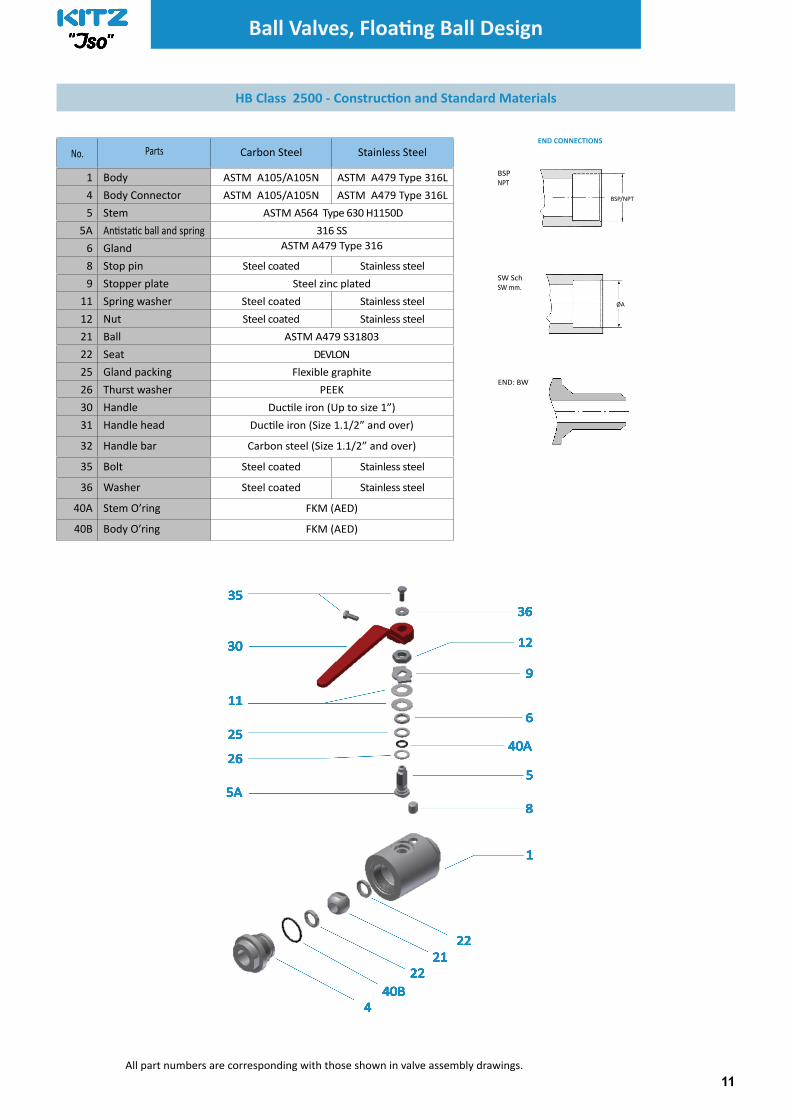
HB Class 2500 - Construc� on and Standard Materials
END CONNECTIONS
BSP
NPT
BSP/NPT
SW Sch
SW mm.
ØA
END: BW
All part numbers are corresponding with those shown in valve assembly drawings.
No. Parts Carbon Steel Stainless Steel
1 Body ASTM A105/A105N ASTM A479 Type 316L
4 Body Connector ASTM A105/A105N ASTM A479 Type 316L
5 Stem ASTM A564 Type 630 H1150D
5A An! sta! c ball and spring 316 SS
6 Gland ASTM A479 Type 316
8 Stop pin Steel coated Stainless steel
9 Stopper plate Steel zinc plated
11 Spring washer Steel coated Stainless steel
12 Nut Steel coated Stainless steel
21 Ball ASTM A479 S31803
22 Seat DEVLON
25 Gland packing Flexible graphite
26 Thurst washer PEEK
30 Handle Duc! le iron (Up to size 1”)
31 Handle head Duc! le iron (Size 1.1/2” and over)
32 Handle bar Carbon steel (Size 1.1/2” and over)
35 Bolt Steel coated Stainless steel
36 Washer Steel coated Stainless steel
40A Stem O’ring FKM (AED)
40B Body O’ring FKM (AED)

Pressure-temperature ratings and other performance data published in this catalog have been
developed from our design calculation, in-house testing, fi eld reports provided by our customers
and/or published offi cial standards or specifi cations. They are good only to cover typical applications
as a general guideline to users of KITZ products introduced in this catalog.
For any specifi c application, users are kindly requested to contact KITZ Corporation of Europe for
technical advice, or to carry out their own study and evaluation for proving suitability of these
products to such an application. Failure to follow this request could result in property damage and/
or personal injury, for which we shall not be liable.
While this catalog has been compiled with the utmost care, we assume no responsibility for errors,
impropriety or inadequacy. Any information provided in this catalog is subject to from time-to-time
change without notice for error rectifi cation, product discontinuation, design modifi cation, new
product introduction or any other cause that KITZ Corporation of Europe considers necessary. This
edition cancels all previous issues.
CAUTION
Kitz Corporation of Europe S.A.
Ramón Viñas, 8
08930 Sant Adrià de Besòs
Barcelona
Spain - España
Ph. +34 93 462 14 08
Fax. +34 93 462 03 49
www.kitzeurope.com
EN-30-712-1