Embed Size (px)
Citation preview
1 of 2 | P a g e
SAWYER CHASSIS
BASIC SETUP INSTRUCTIONS
Before starting you will need to gather a few items, which are necessary to setup your Sawyer Chassis:
� A set of reliable scales
� A clean, LEVEL, floor. Try to place the scales in the same spot on the floor each time you setup your car
for consistency. Also, mark the scales according to which wheel they will be used on and use them on the same wheel each time you use them.
� Two Sawyer setup blocks (wood blocks will work), one measuring 3011/16" tall and one measuring 203/4" tall.
� A ½” wrench to adjust the torsion bars with. � The driver of the car or enough ballast to duplicate the weight of the driver.
Now that you've gathered the necessary tools you'll need to do some preparation to the car.
� The amount of stagger required for a typical Feature at your home track needs to be put on the car.
• Heavy or Tacky tracks = 901/2" to 11"
• Slick or Dry tracks = 701/2" to 9"
� The air pressure needs to be set in the tires. Typical settings are as follows:
• LF: 6PSI RF: 8PSI • LR: 4PSI RR: 6PSI
� The fuel needs to be set at approximately 3 gallons.
After you have gathered the tools needed and have prepared the car with the correct stagger, tire pressure
and fuel level, you are ready to begin the basic setup process.
1) Place the car on the scales and be sure to center each wheel on the scales.
2) Disconnect the rear shocks from the torsion arms in order to allow the torsion bars to support the weight of
the car.
3) Allow the driver to get into the car, being careful not to let the car roll off of the scales or become un0
centered.
4) Now you'll need the 3011/16" block and the ½” wrench you were asked to get earlier. You need to get
the 3011/16" block to slide between the rear axle and the bottom frame rail. To do this, use the ½” wrench
to adjust the torsion stops until the block slides between, as mentioned above. Keep in mind, the block
needs to slide between the axle and frame ON BOTH SIDES.
5) After you've completed step 4 and the rear of the car is blocked at 3011/16", get your 203/4" block and go to the right front wheel of the car. Just like in the rear, this 203/4" block needs to fit snuggly between the
front axle and the bottom frame rail on the right front of the car. To do this, simply raise or lower the car using the coil adjuster on the right front shock until the 203/4" block slides as mentioned above.
� HIGHLIGHT: It is very likely that after you get the 203/4" block to fit under the right front, the rear of the car will need to be adjusted again in order for the 3011/16" blocks to fit correctly. It is very important that both blocks fit in their designated areas before moving on.

2 of 2 | P a g e
6) Now it's time to read the scales. What you're trying to get to is 50/50 cross weight. You get this when the weight of the right rear (RR) + left front (LF) is equal to the weight of the left rear (LR) + right front (RF).
• For example:
LF = 180 lbs. RF = 120 lbs.
LR = 250 lbs. RR = 210 lbs.
� LR + RF = 370 lbs. – This is the amount of "LEFT BIAS" you have.
� RR + LF = 390 lbs. 0 This is the amount of "RIGHT BIAS" you have.
� So, according to these weights we have a total of 20 pounds of 'RIGHT BIAS" weight in the car. We want these weights to be equal if possible so we need to adjust this 20 pounds of "RIGHT BIAS" out of the car.
7) In order to adjust this weight out and get to 50/50 cross weight, you need to go to the left front shock of the
car. By adjusting the coil adjuster on the left front shock you can either add or take away 'RIGHT BIAS"
weight.
• To add "RIGHT BIAS", add turns into the coil adjuster.
• To take away "RIGHT BIAS", remove turns from the coil adjuster.
� In this example, since we have too much "RIGHT BIAS". In the car, we need to turn the left front
coil adjuster counterclockwise. How much adjustment is needed will be different from car to car.
� Typically 1 turn equals 1% on scales.
8) After you make the appropriate adjustments to the left front shock coil, to get the correct cross weight,
repeat steps 4 & 5 until both blocks fit in the appropriate places, then check the scales again to see if the
adjustments you made in step 7 got you to your target of 50/50 cross weight.
Initially, it may be necessary to repeat steps 4 through 7 several times in order to get your car setup correctly.
However, after you become more familiar with this process and do it a few times, it will become much easier and
should not take more than 15 minutes to do.
Hopefully this will be a helpful guide that will give you a better idea about how to prepare your Sawyer Chassis to go to the race track. Remember that no matter what shocks, springs, torsion bars, or tires you choose to run, follow
these steps when setting up your Sawyer Chassis.
If you have any questions regarding these procedures or are unclear as to what we mean in some of the steps,
please call Monday through Thursday from 9 a.m. to 6 p.m., CST.
Suggestions
This is also a good time to troubleshoot your car. A few things to look for are:
• Bent shocks 0 take shocks off and move by hand to see if they operate smoothly.
• Steering shaft 0 make sure the shaft is telescoping in and out properly and is not bound up. • Rod ends 0 check all rod ends looking for bent ones or for loose jam nuts. • Nuts & Bolts 0 wrench on ALL nuts and bolts to make sure you don't have anything loose.
Sawyer Chassis now sells digital scales for use in setting up your car as described above. Take the guesswork out of your chassis setup and know exactly what weight you have, and where. A great investment if you want to go
fast. Call for pricing, 918025802944.
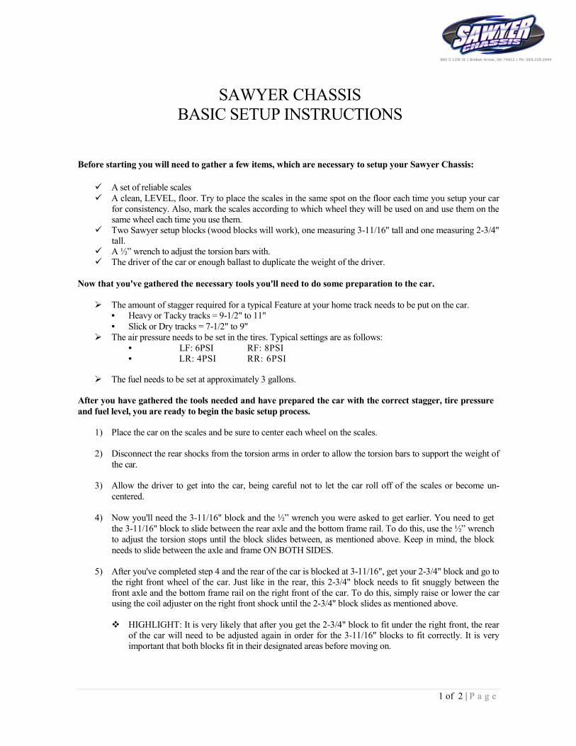
Instructions for adjusting E-model eye on
2014 Sawyer Micro-sprint shocks
Adjusting Dampening of the shock can be adjusted by turning the detent wheel to
any location on the 9 position adjusting range. To increase the dampening,
turn the wheel clockwise and to decrease dampening turn counter-clockwise.
Initially start adjusting wheel from the full clockwise position (full
stiff) and then turn wheel to the desired shock dampening position. A small
setscrew in the detent wheel creates a stop for full stiff and full soft
position. This setscrew must not be removed at any time.
Setting Gas Pressure in Shocks
Gas pressure is to be set with shock fully extended.
The shock is pressurized through the Schrader valve on the shock by using the A.R.S. #40887 inflation
tool that screws on the Schrader valve of the shock with a special fitting.
1. Back the Wing Nut off all the way (counter-clockwise) on the Pressurizing Tool before screwing it on to the
Schrader Valve of the shock.
2. Tighten the Hex Nut Coupler on to the Schrader Valve. Do not over tighten and damage valve or tool.
3. Screw Wing Nut all the way clockwise so it pierces the valve core of the Schrader Valve on the shock.
4. Pressurize the shock to your desired pressure through the valve stem on the tool using Nitrogen Gas Only.
5. After the gas pressure is set in the shock, back the Wing Nut all the way out, (counter-clockwise) so the valve
core is seated in valve stem of the shock.
6. Put an open-end wrench on the Hex nut of the Schrader Valve to insure that it does not loosen out of the
shock when removing the Pressurizing Tool from the shock.
**** You will hear gas pressure escape when you remove the tool from the shock. If the wing nut was backed
off before removing the hex nut from Schrader Valve this gas you hear is only gas stored in the line of the tool.
Tuning the Gas Pressure The nitrogen gas pressure in the 3200 series mono-tube shock is
required at all times in the shock to make it function properly under
racing conditions. The gas pressure in the shock can be adjusted to
accommodate various racetrack conditions.
Decreasing the pressure in the rear shocks allows for more weight
transfer to the rear suspension and provides for more traction on the rear
tires. Increasing the gas pressure in the rear shocks can loosen or free
the chassis up throughout the corner of the race track.
The nitrogen gas pressure in this shock can be adjusted from
5 p.s.i. to 30 p.s.i. to accommodate various race conditions.

Left Front (10psi.)
Counter-clockwise <------------------------------------> Clockwise
FULL SOFT FULL STIFF
POSITION POSITION POSITION POSITION POSITION POSITION POSITION POSITION POSITION
#1 #2 #3 #4 #5 #6 #7 #8 #9
Dry Slick Average Heavy
______________________________________________________________________
Right Front (10psi.)
Counter-clockwise <------------------------------------> Clockwise
FULL SOFT FULL STIFF
POSITION POSITION POSITION POSITION POSITION POSITION POSITION POSITION POSITION
#1 #2 #3 #4 #5 #6 #7 #8 #9
Dry Slick Average Heavy
______________________________________________________________________
Left Rear (10psi.)
Counter-clockwise <------------------------------------> Clockwise
FULL SOFT FULL STIFF
POSITION POSITION POSITION POSITION POSITION POSITION POSITION POSITION POSITION
#1 #2 #3 #4 #5 #6 #7 #8 #9
Heavy Average Dry Slick
______________________________________________________________________
Right Rear
Counter-clockwise <------------------------------------> Clockwise
FULL SOFT FULL STIFF
POSITION POSITION POSITION POSITION POSITION POSITION POSITION POSITION POSITION
#1 #2 #3 #4 #5 #6 #7 #8 #9
Heavy Average Dry Slick
______________________________________________________________________ 20 psi. 15 psi. 10 psi.
_____________________________________________________________________
Recommended Pressure

Sawyer Chassis Track Sheets
Track & Size: Track City & State:Stumble
Air Temp: ADR:_______ Main
High Speed
HEAT RACE FEATURE RACE
Fuel Start:_______ Fuel End:_______ Fuel Start:______ Fuel End:______
Gear:___________ Gear:__________
Tire Compound:__________ Tire Compound:__________
Right Rear Spacing:__________ Right Rear Spacing:__________
PRESSURE PRESSURE
Left Rear Right Rear Left Rear Right Rear
TIRE SIZE TIRE SIZE
Left Rear Right Rear Left Rear Right Rear
Stagger:__________ Stagger:__________
TURNS IN CAR TURNS IN CAR
Left Front Right Front Left Front Right Front
Left Rear Right Rear Left Rear Right Rear
SPRING/BAR SPRING/BAR
Left Front Right Front Left Front Right Front
Left Rear Right Rear Left Rear Right Rear
Start Pos:_____ Finish Pos:____ Start Pos:_____ Finish Pos:_____
NOTES:
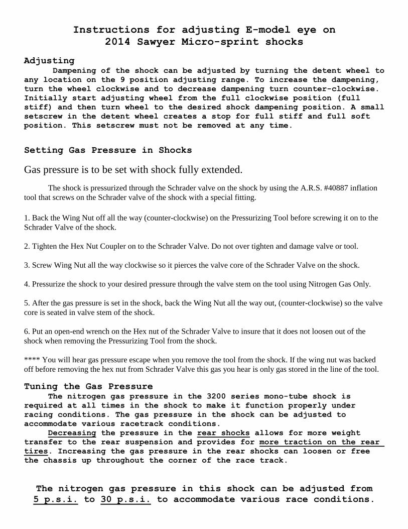
Engler Fuel Injection Data RecordTRACK DATE
ADR % ADR FT. ADR % ADR FT.
STUMBLE PSI. STUMBLE PSI.
MAIN PSI. MAIN PSI.
HIGH SPEED PSI. HIGH SPEED PSI.
MIN MAX MIN MAX
0)7200 STUMBLE 0)7200 STUMBLE
8000)16500 MAIN 8000)16500 MAIN
12000)16500 HIGH SPEED 12000)16500 HIGH SPEED
AIR DENSITY READINGS
PILL SIZE/PSI. START PILL SIZE/PSI. START
LAMBDA LAMBDA
RPM RPM
Front
Hole
Rear
Hole
Front
Hole
Rear
Hole
Front
Hole
Rear
Hole
Front
Hole
Rear
Hole
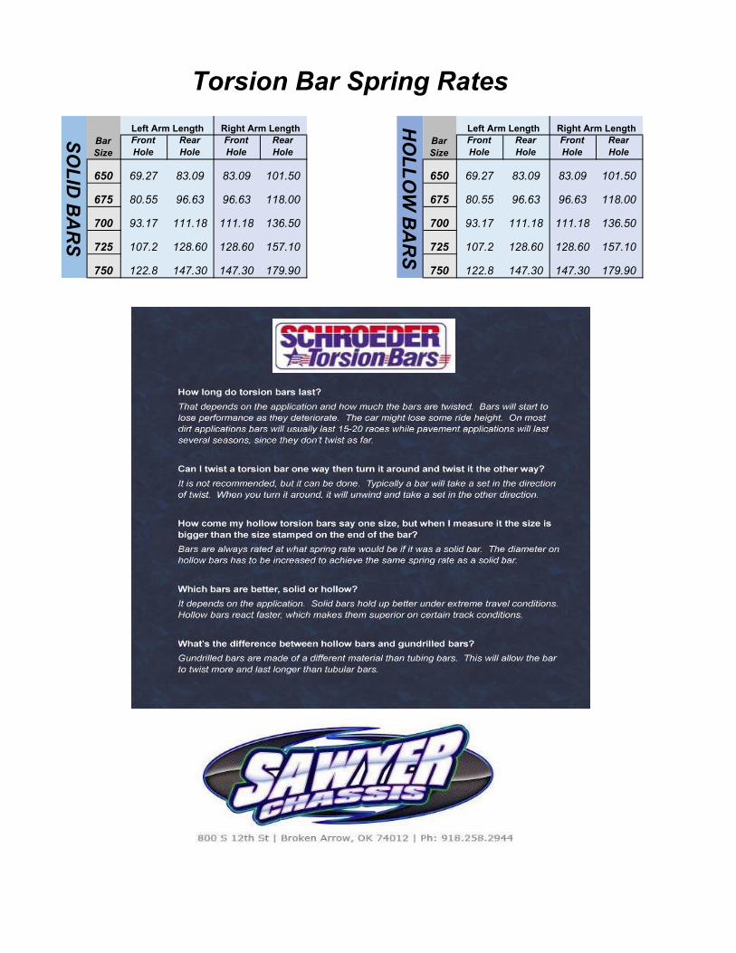
650 69.27 83.09 83.09 101.50 650 69.27 83.09 83.09 101.50
675 80.55 96.63 96.63 118.00 675 80.55 96.63 96.63 118.00
700 93.17 111.18 111.18 136.50 700 93.17 111.18 111.18 136.50
725 107.2 128.60 128.60 157.10 725 107.2 128.60 128.60 157.10
750 122.8 147.30 147.30 179.90 750 122.8 147.30 147.30 179.90
HO
LL
OW
BA
RS
Left Arm Length Right Arm Length
Bar
Size
Bar
Size
Left Arm Length Right Arm Length
Torsion Bar Spring Rates
SO
LID
BA
RS

New Axle3" spacer
New Axle1 7/8" spacer
New Axle2 1/4" spacer
BearingInsert.200
spacer
BearingInsert .200
spacer

C
B
AA
B
C
D
12345678
8 7 6 5 4 3 2 1
E
F
E
D
F
1
ITEM NO. PART NUMBER DESCRIPTION QTY.1 SAW 12 23 1
4 6
5 2
6 47 168 29 210 611 212 313 214 115 316 317 2
18 6
19 4
20 1
21 222 1
23 4
24 225 226 127 SROKET 1
28 3
29 3
30 5
31 3
32 1
33SPIRAL
RETAININGRING
1
34 135 1
36 4
37 138 139 140 341 342 2
43 2
44 2
45 246 1
47BRAKEROTOR
ASSEMBLY1
48 649 250 151 152 153 254 155 156 157 158 159 160 161 262 163 164 2
65 2
66 267 268 269 270 2
8
70
53
61
8
4
52
10
53
10
66
14
18
18
51
16
55
15
68
59
60
22
56
57
65
64
5
61
23
24
7
9
69 69
65
68
63
47
6462
70
49
27
32
2150
18"
13.50
9
19
665556
21
62
13
19
19
13
21
95059
A
A
B
B
SECTION A-ASCALE 1 : 3
SECTION B-BSCALE 1 : 3

25
11
22
15
24
23
32
17
10
6
16
13
9
4
812
1
263
31
2
14
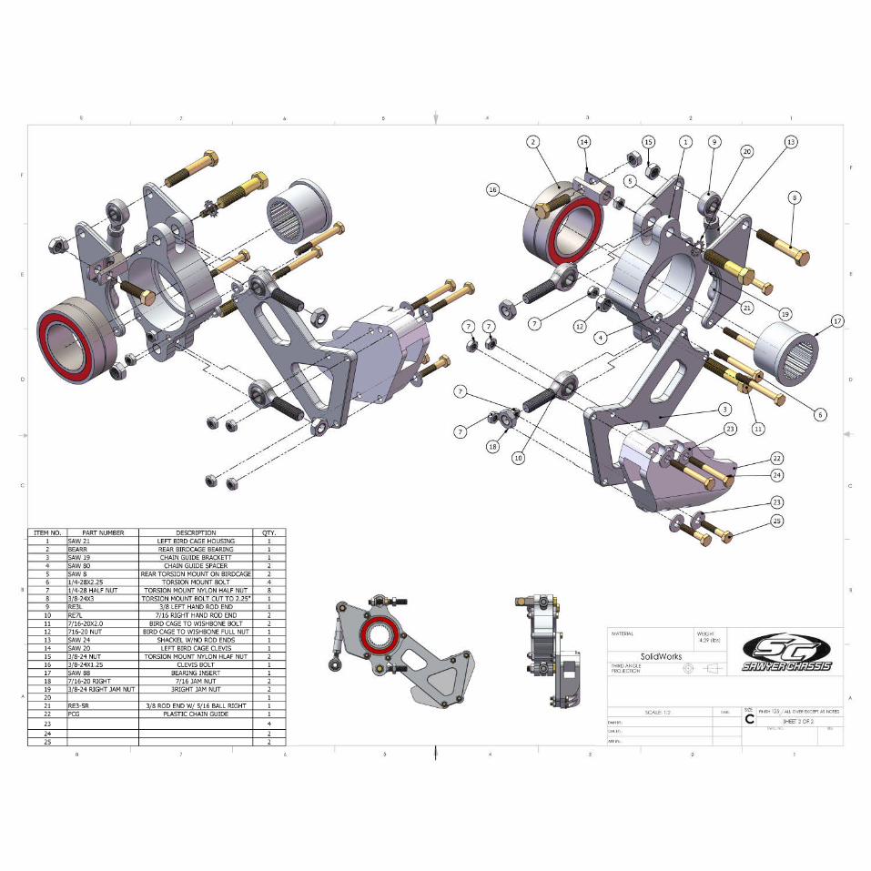
ITEM NO. PART NUMBER DESCRIPTION QTY.
1 RRB RIGHT REAR BIRDCAGE 1
2 BEARL LEFT REAR BIRDCAGE BEARING 1
3 SPIRAL RETAINING RING 1
4 SAW 88 BEARING INSERT 1
6 CALIPER ASSEMBLY 1
8 1/4" NPT SOCKET HEX HEAD PLUG 1
9 BRAKE PAD CLIP 1
10 BREAK LINE FITTING 1
11 BLEEDER FITTING 3
12 BLEEDER PLUG 3
13 BRAKE PAD 2
14 BRAKE PAD SHIM 2
15 3/8-24X1.25" GRADE 8 HEX HEAD BOLT 2
16 3/8 FLAT WASHER 2
17 3/8-24 HALF LOCK NUT 2
19 BRAKE ROTOR ASSEMBLY 1
22 3/8-24X2.25" GRADE 8 HEX HEAD BOLT 1
23 3/8-24 HALF LOCK NUT 1
24 7/16 ROD END RIGHT 2
25 3/8-24X2.5" GRADE 8 HEX HEAD BOLT 2
26 7/16 JAM NUT RIGHT 2
27 3/8 ROD END W/ 5/16 BALL RIGHT 1
28 3/8 ROD END RIGHT 1
29 SAW 24 SHACKLE W/ NO ROD END 1
30 3/8-24 RIGHT 3/8-24 RIGHT JAM NUT 2
31 BRAKE ROTOR/BIRDCAGE SPACER 1
32 3/8-24 HALF LOCK NUT 2
FINISH ALL OVER EXCEPT AS NOTED125
A
CHK BY:
APP BY:
DWN BY: CDWG. NO. REV
D
C
B
A
B
C
D
12345678
8 7 6 5 4
MATERIAL
3 2 1
E
F
E
F
SIZE
PROJECTIONTHIRD ANGLE
WEIGHT
30
15
28
25
29
30
19
27
22
10
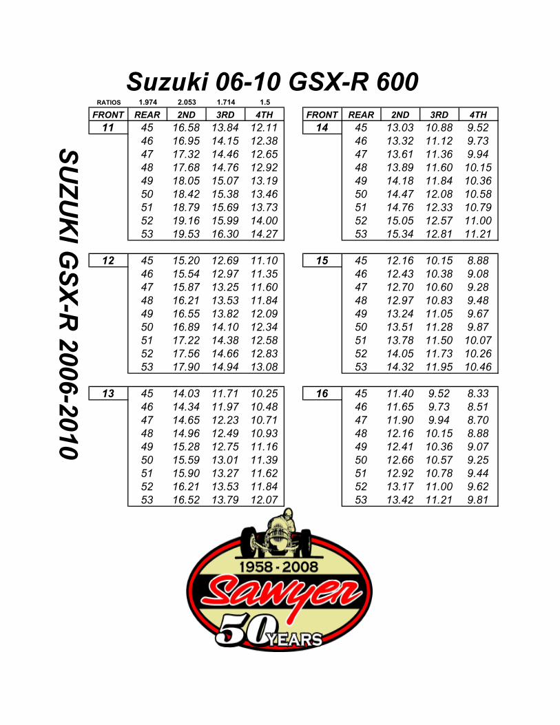
RATIOS 1.974 2.053 1.714 1.5
FRONT REAR 2ND 3RD 4TH FRONT REAR 2ND 3RD 4TH
11 45 16.58 13.84 12.11 14 45 13.03 10.88 9.52
46 16.95 14.15 12.38 46 13.32 11.12 9.73
47 17.32 14.46 12.65 47 13.61 11.36 9.94
48 17.68 14.76 12.92 48 13.89 11.60 10.15
49 18.05 15.07 13.19 49 14.18 11.84 10.36
50 18.42 15.38 13.46 50 14.47 12.08 10.58
51 18.79 15.69 13.73 51 14.76 12.33 10.79
52 19.16 15.99 14.00 52 15.05 12.57 11.00
53 19.53 16.30 14.27 53 15.34 12.81 11.21
12 45 15.20 12.69 11.10 15 45 12.16 10.15 8.88
46 15.54 12.97 11.35 46 12.43 10.38 9.08
47 15.87 13.25 11.60 47 12.70 10.60 9.28
48 16.21 13.53 11.84 48 12.97 10.83 9.48
49 16.55 13.82 12.09 49 13.24 11.05 9.67
50 16.89 14.10 12.34 50 13.51 11.28 9.87
51 17.22 14.38 12.58 51 13.78 11.50 10.07
52 17.56 14.66 12.83 52 14.05 11.73 10.26
53 17.90 14.94 13.08 53 14.32 11.95 10.46
13 45 14.03 11.71 10.25 16 45 11.40 9.52 8.33
46 14.34 11.97 10.48 46 11.65 9.73 8.51
47 14.65 12.23 10.71 47 11.90 9.94 8.70
48 14.96 12.49 10.93 48 12.16 10.15 8.88
49 15.28 12.75 11.16 49 12.41 10.36 9.07
50 15.59 13.01 11.39 50 12.66 10.57 9.25
51 15.90 13.27 11.62 51 12.92 10.78 9.44
52 16.21 13.53 11.84 52 13.17 11.00 9.62
53 16.52 13.79 12.07 53 13.42 11.21 9.81
Suzuki 06�10 GSX�R 600
SU
ZU
KI G
SX
�R 2
006�2
010

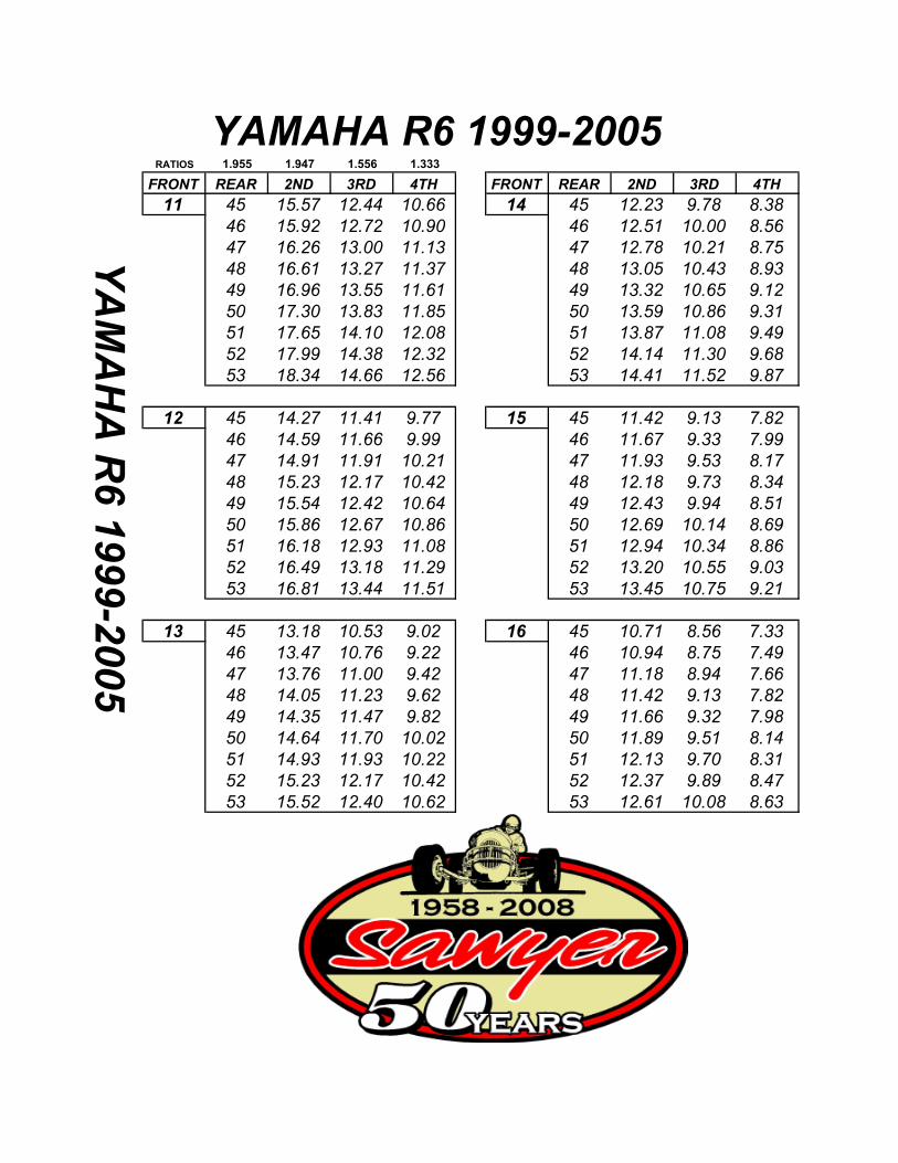
RATIOS 1.955 1.947 1.556 1.333
FRONT REAR 2ND 3RD 4TH FRONT REAR 2ND 3RD 4TH
11 45 15.57 12.44 10.66 14 45 12.23 9.78 8.38
46 15.92 12.72 10.90 46 12.51 10.00 8.56
47 16.26 13.00 11.13 47 12.78 10.21 8.75
48 16.61 13.27 11.37 48 13.05 10.43 8.93
49 16.96 13.55 11.61 49 13.32 10.65 9.12
50 17.30 13.83 11.85 50 13.59 10.86 9.31
51 17.65 14.10 12.08 51 13.87 11.08 9.49
52 17.99 14.38 12.32 52 14.14 11.30 9.68
53 18.34 14.66 12.56 53 14.41 11.52 9.87
12 45 14.27 11.41 9.77 15 45 11.42 9.13 7.82
46 14.59 11.66 9.99 46 11.67 9.33 7.99
47 14.91 11.91 10.21 47 11.93 9.53 8.17
48 15.23 12.17 10.42 48 12.18 9.73 8.34
49 15.54 12.42 10.64 49 12.43 9.94 8.51
50 15.86 12.67 10.86 50 12.69 10.14 8.69
51 16.18 12.93 11.08 51 12.94 10.34 8.86
52 16.49 13.18 11.29 52 13.20 10.55 9.03
53 16.81 13.44 11.51 53 13.45 10.75 9.21
13 45 13.18 10.53 9.02 16 45 10.71 8.56 7.33
46 13.47 10.76 9.22 46 10.94 8.75 7.49
47 13.76 11.00 9.42 47 11.18 8.94 7.66
48 14.05 11.23 9.62 48 11.42 9.13 7.82
49 14.35 11.47 9.82 49 11.66 9.32 7.98
50 14.64 11.70 10.02 50 11.89 9.51 8.14
51 14.93 11.93 10.22 51 12.13 9.70 8.31
52 15.23 12.17 10.42 52 12.37 9.89 8.47
53 15.52 12.40 10.62 53 12.61 10.08 8.63
YAMAHA R6 1999�2005
YA
MA
HA
R6 1
999�2
005


RATIOS 2.073 2.000 1.667 1.444
FRONT REAR 2ND 3RD 4TH FRONT REAR 2ND 3RD 4TH
11 45 16.96 14.14 12.25 14 45 13.33 11.11 9.62
46 17.34 14.45 12.52 46 13.62 11.35 9.84
47 17.71 14.77 12.79 47 13.92 11.60 10.05
48 18.09 15.08 13.06 48 14.21 11.85 10.26
49 18.47 15.39 13.33 49 14.51 12.09 10.48
50 18.85 15.71 13.61 50 14.81 12.34 10.69
51 19.22 16.02 13.88 51 15.10 12.59 10.90
52 19.60 16.34 14.15 52 15.40 12.84 11.12
53 19.98 16.65 14.42 53 15.70 13.08 11.33
12 45 15.55 12.96 11.23 15 45 12.44 10.37 8.98
46 15.89 13.25 11.47 46 12.71 10.60 9.18
47 16.24 13.53 11.72 47 12.99 10.83 9.38
48 16.58 13.82 11.97 48 13.27 11.06 9.58
49 16.93 14.11 12.22 49 13.54 11.29 9.78
50 17.28 14.40 12.47 50 13.82 11.52 9.98
51 17.62 14.69 12.72 51 14.10 11.75 10.18
52 17.97 14.97 12.97 52 14.37 11.98 10.38
53 18.31 15.26 13.22 53 14.65 12.21 10.58
13 45 14.35 11.96 10.36 16 45 11.66 9.72 8.42
46 14.67 12.23 10.59 46 11.92 9.94 8.61
47 14.99 12.49 10.82 47 12.18 10.15 8.79
48 15.31 12.76 11.05 48 12.44 10.37 8.98
49 15.63 13.03 11.28 49 12.70 10.58 9.17
50 15.95 13.29 11.51 50 12.96 10.80 9.35
51 16.27 13.56 11.74 51 13.22 11.02 9.54
52 16.58 13.82 11.97 52 13.47 11.23 9.73
53 16.90 14.09 12.20 53 13.73 11.45 9.92
YAMAHA R6 2006�2009
YA
MA
HA
R6 2
006�2
009

ITEM NO. PART NUMBER DESCRIPTION QTY.
1 Rear Motor Mount (right) 1
2 Rear Motor Mount (left) 1
3 7/16-20 Lock nut 2
4 7/16 Flat Washer 95 3/8-24 x 8.5" Grade 8 Hex Bolt 26 3/8 Flat Washer 27 3/8-24 Lock Nut 1
8 2
9 7/16-20X1.5" Grade 8 Hex Bolt 2
10 front Motor Mount 1
11 1
12 7/16-20-1.75" Grade * Hex Bolt 2
13 front Motor Mount (right) 1
14 3/8-24 x 1" Grade 8 Hex Bolt 1
15 3/8 Flat Washer 2
16 .375" Spacer 3
17 7/16 x .1" Washer 3
18 7/16 Star Lock Washer 2
19 10MM-1.5MM x 35MM 3
20 1" Spacer 1
21 .25" Spacer 1
15
3
9
4
9
6
7
16
4
16
21
17
15
16
4
8
10
4
21 14
15
6
16
9
7
13
1
17
8
20
2
5
12
11
19
18
15
19
34
1612
4
5
184
16
44
4
9
M10 7/1620 X 1" Tapered Bolt
front Motor Mount (bottom left)
(top left)SAW 99
SAW 97
SAW 106
SAW 98SAW 98
SAW 25
SAW 38
SAW 37
0609 YAMAHAR6R
All Black