Embed Size (px)
Citation preview
SAWS WATER PROJECTS MODELING CRITERIA GUIDELINES
July 2016
2800 U.S. Highway 281 North
San Antonio, Texas 78212
Modeling Criteria Guidelines, July 2016
2
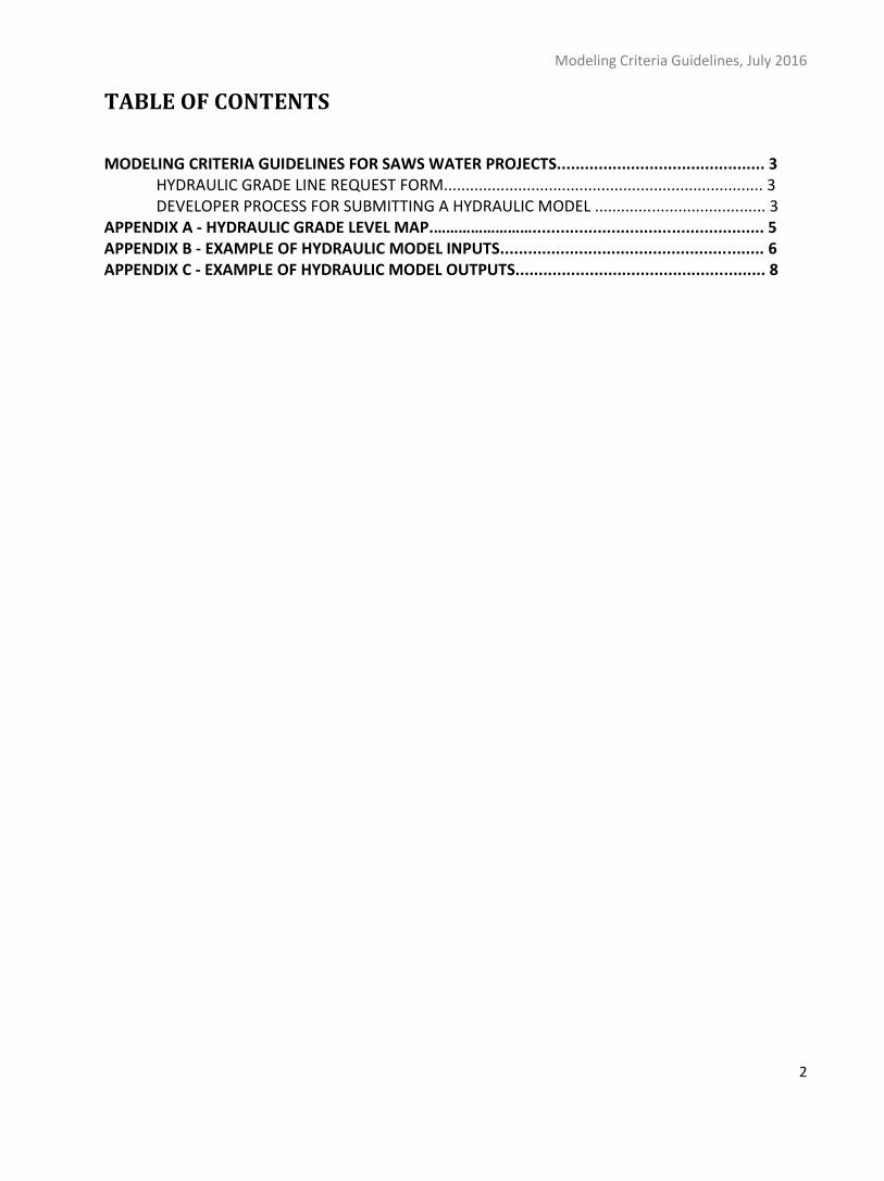
TABLE OF CONTENTS
MODELING CRITERIA GUIDELINES FOR SAWS WATER PROJECTS............................................. 3 HYDRAULIC GRADE LINE REQUEST FORM......................................................................... 3 DEVELOPER PROCESS FOR SUBMITTING A HYDRAULIC MODEL ....................................... 3
APPENDIX A - HYDRAULIC GRADE LEVEL MAP.…………………….................................................. 5 APPENDIX B - EXAMPLE OF HYDRAULIC MODEL INPUTS......................................................... 6 APPENDIX C - EXAMPLE OF HYDRAULIC MODEL OUTPUTS...................................................... 8
Modeling Criteria Guidelines, July 2016
3
Modeling Criteria Guidelines for SAWS Water Projects
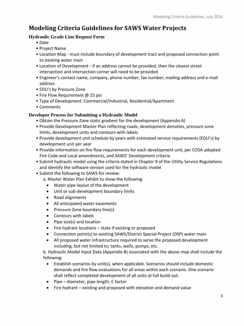
Hydraulic Grade Line Request Form
• Date • Project Name • Location Map - must include boundary of development tract and proposed connection point
to existing water main • Location of Development - if an address cannot be provided, then the closest street
intersection and intersection corner will need to be provided • Engineer’s contact name, company, phone number, fax number, mailing address and e-mail
address • EDU’s by Pressure Zone • Fire Flow Requirement @ 25 psi • Type of Development: Commercial/Industrial, Residential/Apartment • Comments
Developer Process for Submitting a Hydraulic Model
• Obtain the Pressure Zone static gradient for the development (Appendix A) • Provide Development Master Plan reflecting roads, development densities, pressure zone
limits, development units and contours with labels • Provide development unit schedule by years with estimated service requirements (EDU’s) by
development unit per year • Provide information on fire flow requirements for each development unit, per COSA adopted
Fire Code and Local amendments, and SAWS’ Development criteria • Submit hydraulic model using the criteria stated in Chapter 9 of the Utility Service Regulations
and identify the software version used for the hydraulic model • Submit the following to SAWS for review:
a. Master Water Plan Exhibit to show the following:
Water pipe layout of the development
Unit or sub-development boundary limits
Road alignments
All anticipated water easements
Pressure Zone boundary line(s)
Contours with labels
Pipe size(s) and location
Fire hydrant locations – state if existing or proposed
Connection point(s) to existing SAWS/District Special Project (DSP) water main
All proposed water infrastructure required to serve the proposed development including, but not limited to; tanks, wells, pumps, etc.
b. Hydraulic Model Input Data (Appendix B) associated with the above map shall include the following:
Establish scenarios by unit(s), when applicable. Scenarios should include domestic demands and fire flow evaluations for all areas within each scenario. One scenario shall reflect completed development of all units at full build-out.
Pipe – diameter, pipe length, C factor
Fire hydrant – existing and proposed with elevation and demand value
Modeling Criteria Guidelines, July 2016
4
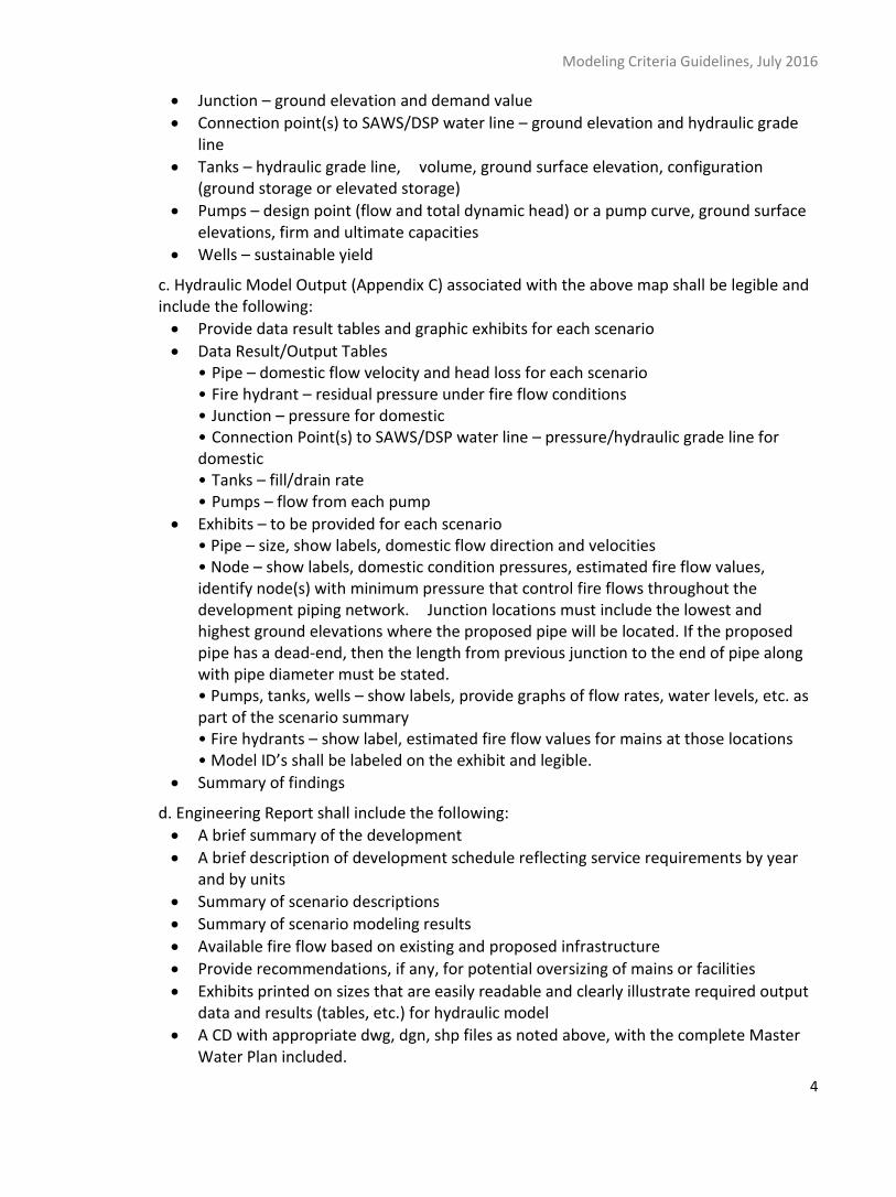
Junction – ground elevation and demand value
Connection point(s) to SAWS/DSP water line – ground elevation and hydraulic grade line
Tanks – hydraulic grade line, volume, ground surface elevation, configuration (ground storage or elevated storage)
Pumps – design point (flow and total dynamic head) or a pump curve, ground surface elevations, firm and ultimate capacities
Wells – sustainable yield
c. Hydraulic Model Output (Appendix C) associated with the above map shall be legible and include the following:
Provide data result tables and graphic exhibits for each scenario
Data Result/Output Tables • Pipe – domestic flow velocity and head loss for each scenario • Fire hydrant – residual pressure under fire flow conditions • Junction – pressure for domestic • Connection Point(s) to SAWS/DSP water line – pressure/hydraulic grade line for domestic • Tanks – fill/drain rate • Pumps – flow from each pump
Exhibits – to be provided for each scenario • Pipe – size, show labels, domestic flow direction and velocities • Node – show labels, domestic condition pressures, estimated fire flow values, identify node(s) with minimum pressure that control fire flows throughout the development piping network. Junction locations must include the lowest and highest ground elevations where the proposed pipe will be located. If the proposed pipe has a dead-end, then the length from previous junction to the end of pipe along with pipe diameter must be stated. • Pumps, tanks, wells – show labels, provide graphs of flow rates, water levels, etc. as part of the scenario summary • Fire hydrants – show label, estimated fire flow values for mains at those locations • Model ID’s shall be labeled on the exhibit and legible.
Summary of findings
d. Engineering Report shall include the following:
A brief summary of the development
A brief description of development schedule reflecting service requirements by year and by units
Summary of scenario descriptions
Summary of scenario modeling results
Available fire flow based on existing and proposed infrastructure
Provide recommendations, if any, for potential oversizing of mains or facilities
Exhibits printed on sizes that are easily readable and clearly illustrate required output data and results (tables, etc.) for hydraulic model
A CD with appropriate dwg, dgn, shp files as noted above, with the complete Master Water Plan included.
930
750
830
828
1111
994
790
1170
1400
950
1125
1610 1258
1060
790
846
1400
950
1080950
1125
1170
1520
12951610
1044
823
1400 1012
1820
1200
994
730
18201258
920
1610
15301636
9101170 1065
1530
1170
15401540
1233
1130
1201
1500
15301530
1378
1536
1640
1258
837
1082
1450
1338
1010
11721500
1107
1044
§̈¦37
§̈¦10
§̈¦35
§̈¦410 §̈¦90§̈¦35
§̈¦10
§̈¦410£¤281
£¤87
£¤151
£¤181
")1604
")1604
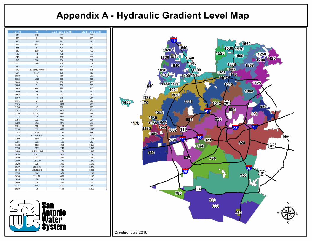
HGL (ft) PZ Max Ground Elev (ft) Min Ground Elev (ft) 730 730 601 530750 2 620 420790 790 661 490823 823 708 654828 3 700 580830 830 720 472837 4B 720 630846 4A 730 630910 910 756 692920 920 760 632930 4 800 680950 4C, 950E, 950W 850 608994 5, 5A 870 760
1010 7C 910 8801012 1012 890 7601044 7A 950 7981060 6 930 8001065 6W 930 8001080 1080 951 7301082 7B 953 8501107 7D 978 9641111 7 980 8601125 9 1000 7801130 8D 980 9201148 10Y 1000 9741170 8, 1170 1041 7651172 10C 1010 9801184 10Z 1055 9941200 1200 1071 7961201 11F 1100 9801210 11L 1080 10601233 10D 1140 9681258 10, 10A, 10B 1130 9001290 11N 1198 11351295 10X 1166 9501338 11D 1209 10601378 11T 1240 10401400 11, 11A, 11M 1270 10401410 11CTI 1300 12001450 11S 1340 12001500 11B, 11O 1370 12001520 12E 1391 11361530 11E, 11K 1400 12001540 12B, 12SSH 1441 12801536 11C 1360 12501610 12, 12A 1480 11601636 12F 1506 12901640 12C 1460 11501726 14A 1596 13801820 14 1690 1415
Appendix A - Hydraulic Gradient Level Map
µCreated: July 2016

Appendix B - Example of Hydraulic Model Inputs Note: The following examples should be used more as a reference due to varying hydraulic modeling software having different layout styles for model inputs.
Pipe:
Junction:
Modeling Criteria Guidelines, July 2016
7
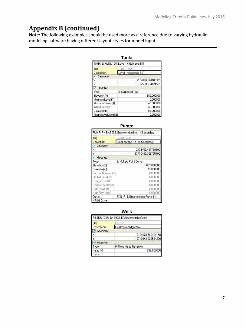
Appendix B (continued) Note: The following examples should be used more as a reference due to varying hydraulic modeling software having different layout styles for model inputs.
Tank:
Pump:
Well:
Modeling Criteria Guidelines, July 2016
8
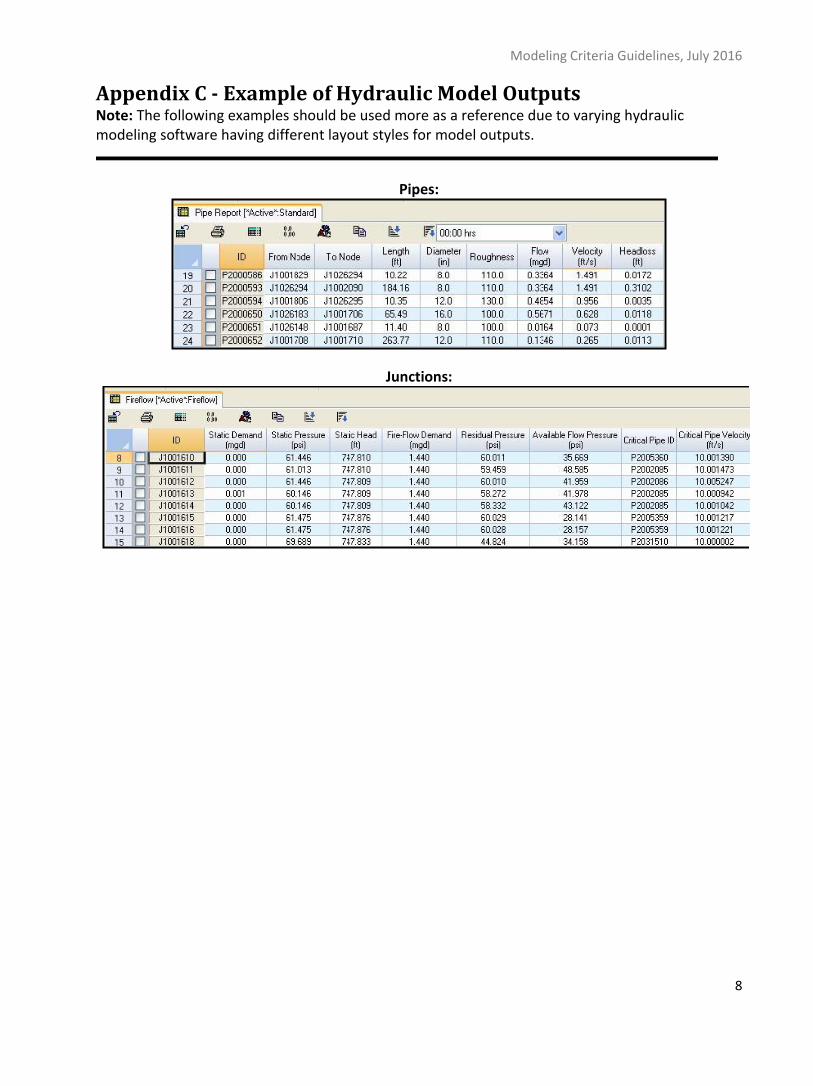
Appendix C - Example of Hydraulic Model Outputs Note: The following examples should be used more as a reference due to varying hydraulic modeling software having different layout styles for model outputs.
Pipes:
Junctions: