Embed Size (px)
Citation preview

Pro Audio 4 Deployment Guide Copyright © 2017 Savant Systems, LLC
009-1413-01 | 170609 1 of 28
Savant Pro Audio 4 SMA-5000-xx
Deployment Guide
!
Document Number: 009-1413-01
Document Date: June 2017
Document Supports: da Vinci 8.4

Pro Audio 4 Deployment Guide Copyright © 2017 Savant Systems, LLC
009-1413-01 | 170609 2 of 28
Contents To access the link to the topics in this document, click the topic text or topic page.
1. Introduction ....................................................................................... 4 1.1. Before You Begin ............................................................................................ 4
2. Deployment Steps ............................................................................ 5 3. Savant Pro Audio 4 Overview .................................................... 6
3.1. Box Contents and Specifications .............................................................. 6 3.2. Front Panel ......................................................................................................... 6 3.3. Rear Panel .......................................................................................................... 7
4. Installation ........................................................................................... 8 4.1. Rack Installation ............................................................................................... 8 4.2. Enclosure Installation ..................................................................................... 8
5. Wiring and Connections ............................................................... 9 5.1. RS-232 Wiring ................................................................................................... 9 5.2. IR Wiring ........................................................................................................... 10 5.3. Speaker Wiring ............................................................................................... 10 5.4. Network Connection ...................................................................................... 11 5.5. AC Power Connection ................................................................................... 11 5.6. Checking and Replacing the Fuse ........................................................... 12
6. Blueprint Configuration ................................................................ 13 6.1. Basic Blueprint Layout ................................................................................. 13 6.2. Adding a Savant Pro Audio 4 to a Configuration .............................. 14 6.3. Assigning Inputs and Outputs (I/Os) ..................................................... 15
7. Savant Pro Audio 4 Web User Interface (Web UI) ........... 16 7.1. Accessing the Web UI .................................................................................. 16 7.2. Pro Audio 4 Status ......................................................................................... 16 7.3. Network Configuration ................................................................................ 17 7.4. Pro Audio 4 Logging .................................................................................... 17 7.5. Input & Output Configuration .................................................................... 18
8. Expansion .......................................................................................... 19 8.1. Blueprint Layout for 2 Devices with a MOTU AVB switch ............. 19 8.2. Adding the MOTU AVB Switch ................................................................ 20 8.3. AVB Info in System Monitor ...................................................................... 20 8.4. Blueprint Layout for 16 Devices with 5 MOTU AVB switches ....... 21
9. Savant Music .................................................................................... 22 Additional Information ....................................................................... 23 Appendix A: Network Requirements ............................................ 24 Appendix B: Document Revision History ................................... 25 Appendix C: Retrieving and Setting IP Address ...................... 26 Appendix D: DNS (Add, Remove, Query) .................................. 27 Important Notice .................................................................................. 28

Pro Audio 4 Deployment Guide Copyright © 2017 Savant Systems, LLC
009-1413-01 | 170609 3 of 28
Important Safety Information - Read First Before installing, configuring, and operating Savant equipment and other vendor equipment, Savant recommends that each dealer, integrator, installer, etc. access and read all the required technical documentation. Savant technical documentation can be located by visiting Savant.com. Vendor documentation is supplied with the equipment.
Read and understand all safety instructions, cautions, and warnings in this document and the labels on the equipment.
Safety Classifications in this Document NOTE: Provides special information for installing,
configuring, and operating the equipment.
IMPORTANT! Provides special information that is critical to installing, configuring, and operating the equipment.
CAUTION! Provides special information for avoiding situations that may cause damage to equipment.
WARNING! Provides special information for avoiding situations that may cause physical danger to the installer, end user, etc.
Electric Shock Prevention ELECTRIC SHOCK!
The source power poses an electric shock hazard that has the potential to cause serious injury to installers and end users.
ELECTRICAL DISCONNECT: The source power outlet and power supply input power sockets should be easily accessible to disconnect power in the event of an electrical hazard or malfunction.
Weight Injury Prevention WEIGHT INJURY!
Installing some of the Savant equipment requires two installers to ensure safe handling during installation. Failure to use two installers may result in injury.
Safety Statements Follow all of the safety instructions listed below and apply where applicable. Additional safety information will be included where applicable.
1. Read these instructions. 2. Keep these instructions. 3. Heed all warnings. 4. Follow all instructions. 5. Do not use this apparatus near water. 6. Clean only with dry cloth. 7. Do not block any ventilation openings. Install in accordance with the
manufacturer's instructions. 8. Do not install near any heat sources such as radiators, heat registers,
stoves, or other apparatus (including amplifiers) that produce heat. 9. Do not defeat the safety purpose of the polarized or grounding-type
plug. A polarized plug has two blades with one wider than the other. A grounding type plug has two blades and a third grounding prong. The wide blade or the third prong is provided for your safety. If the provided plug does not fit into your outlet, consult an electrician for replacement of the obsolete outlet.
10. Protect the power cord from being walked on or pinched particularly at plugs, convenience receptacles, and the point where they exit from the apparatus.
11. Only use attachments/accessories specified by the manufacturer. 12. Use only with the cart, stand, tripod, bracket, or table specified by the
manufacturer, or sold with the apparatus. When a cart is used, use caution when moving the cart/apparatus combination to avoid injury from tip over.
13. Unplug this apparatus during lightning storms or when unused for long periods of time.
14. Refer all servicing to qualified service personnel. Servicing is required when the apparatus has been damaged in any way, such as power supply cord or plug is damaged, liquid has been spilled or objects have fallen into the apparatus, the apparatus has been exposed to rain or moisture, does not operate normally, or has been dropped.
15. To completely disconnect this equipment from the AC mains, disconnect the power supply cord plug from the AC receptacle.

Pro Audio 4 Deployment Guide Copyright © 2017 Savant Systems, LLC
009-1413-01 | 170609 4 of 28
1. Introduction This Deployment Guide will guide the installer through the process of installing, configuring, and adding a Savant Pro Audio 4 to a RacePoint Blueprint® configuration.
1.1. Before You Begin Read through this document in its entirety and ensure that the following required items are available:
Savant Pro Audio 4 ................................................................................................................................................................
Unique ID (UID) of the Pro Audio 4 ................................................................................................................................. (located on the back of the unit)
Savant Host (Smart or Pro) licensed and running da Vinci 8.2 or higher .........................................................
Savant Development Environment (SDE/MacBook®) .............................................................................................. RacePoint Blueprint da Vinci 8.2 or higher
Ethernet network meeting Savant requirements ....................................................................................................... See Appendix A: Network Requirements
Speakers that will be used in the system .......................................................................................................................
Pro Audio 4 Deployment Guide Copyright © 2017 Savant Systems, LLC
009-1413-01 | 170609 5 of 28
2. Deployment Steps Follow these steps to successfully deploy a Savant Pro Audio 4. This page can be used as a checklist to record which steps have been completed.
1. Review product specifications and connection details ............................................................................................... See Pro Audio 4 Overview
2. Install the Savant Pro Audio 4 ............................................................................................................................................... See Installation
3. (Optional) Install a MOTU AVB Switch .............................................................................................................................. See Expansion
4. Add the Savant Pro Audio 4 into a RacePoint Blueprint® configuration .............................................................. See Blueprint Configuration

Pro Audio 4 Deployment Guide Copyright © 2017 Savant Systems, LLC
009-1413-01 | 170609 6 of 28
3. Savant Pro Audio 4 Overview
3.1. Box Contents and Specifications Refer to the Quick Reference Guide for this product located on the Savant Customer Community for Box Contents and Specifications.
3.2. Front Panel
Power LED
Green: System has power and is operating normally. Red: System is in standby mode. In standby mode, most of the controller circuitry is powered down. Off: System is not receiving power.
Status LED
Green Blinking: Embedded system is ready, but no communication has been established with the host. Green: Host has established communications with the embedded system. Red Blinking: Embedded firmware is running, but has not received a DHCP IP Address. Red: Host has determined the firmware needs to be updated, but a problem occurred during the process that will initiate a reset. Amber Blinking: Embedded system has a valid link-local IP Address and is connecting to the host. Amber: Host is updating the embedded firmware. Off: Embedded processor is resetting, or is powered up, and is booting the embedded firmware. Hardware Failure: If a hardware failure occurs, the status LED indication will be interrupted every three seconds with a solid red indication. For example, if the LED is blinking green when a hardware failure occurs, the LED will alternate between blinking green and solid red at three-second intervals.
RS-232 LED Green: RS-232 serial port activity. Off: No RS-232 serial port activity.
IR LED Green: IR port signal activity. Off: No IR port activity.
On/Off button
On: Fully enables all internal power rails and processor. Off: Disables most internal power rails and processor, but not internal AC/DC power supply. Hold On/Off button for about 5 seconds to place into standby mode. The Power LED turns red. Hold On/Off button for about 1 second to take system out of standby mode. The I/O power switch on the back of unit must be On (I) to enable this function. To turn the power off for the entire system, press the I/O power switch on the rear panel to Off (O).
Reset button Resets the network. Hold Reset Button for 5 seconds while powered On to clear network settings. Status LED will blink Red rapidly when reset is complete.
Zone Protection Red: Protection mode has been enabled to protect a zone / channel; Typically indicates thermal protection, clipping or over current. Off: Protection mode has not been enabled.
A EC
B D
F G

Pro Audio 4 Deployment Guide Copyright © 2017 Savant Systems, LLC
009-1413-01 | 170609 7 of 28
3.3. Rear Panel
Speaker Connections (4) Speaker output zones Uses 4-pin Speaker Connectors NOTE: Compatible with 8 ohm or 4 ohm speakers.
Analog Preamp Output (1) Analog stereo line output (Left & Right)
Analog Inputs (2) Analog stereo inputs, RCA line-level inputs; 22 kΩ input impedance.
Digital Audio Out (1) Digital optical preamp output (TOSLINK), line-level 96kHz/24-bit output, fixed volume.
Digital Audio In (2) Digital optical audio inputs (TOSLINK). Supports up to 96kHz/24-bit digital audio in; PCM stereo format only.
IR (4) IR Ports Uses 4-pin IR Connectors to send IR signals to control devices with an IR input or IR receiver via an IR flasher (5V tolerant only). See IR Wiring section for important precautions regarding IR functionality before making any connections.
RS-232 (2) RS-232 Ports 8-pin RJ-45 port used to transmit and receive serial binary data to and from serial controllable devices. CTS/RTS handshaking availability based on component profile. See RS-232 Connections section for pin-outs.
Ethernet 8-pin RJ-45 female. 10/100/1000 Base-T auto-negotiating port with Link/Activity LEDs Supports Audio Video Bridging (AVB)
Ethernet Activity LED Green Blinking: Activity (Rx/Tx) Off: No Activity
Ethernet Link LED Green Solid: Ethernet Link is established Off: Ethernet link is not established
USB USB 2.0 Type A (Reserved for future Use)
Fuse 250V 3A Slow Blow fuse field replaceable.
Power Input 100/240V 50/60 Hz 2.7A
I/O (power switch) I (On): Powers On the controller. O (Off): Powers Off the controller.
NA EC
B D F
I JG L
H K M
Pro Audio 4 Deployment Guide Copyright © 2017 Savant Systems, LLC
009-1413-01 | 170609 8 of 28
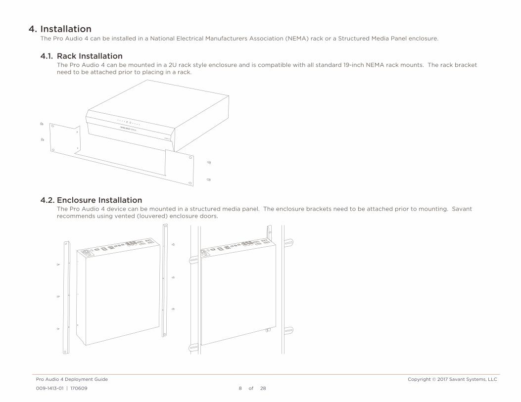
4. Installation The Pro Audio 4 can be installed in a National Electrical Manufacturers Association (NEMA) rack or a Structured Media Panel enclosure.
4.1. Rack Installation The Pro Audio 4 can be mounted in a 2U rack style enclosure and is compatible with all standard 19-inch NEMA rack mounts. The rack bracket need to be attached prior to placing in a rack.
4.2. Enclosure Installation The Pro Audio 4 device can be mounted in a structured media panel. The enclosure brackets need to be attached prior to mounting. Savant recommends using vented (louvered) enclosure doors.

Pro Audio 4 Deployment Guide Copyright © 2017 Savant Systems, LLC
009-1413-01 | 170609 9 of 28
5. Wiring and Connections The Pro Audio 4 control connections send data to control a device and receive data to display current status on the user interfaces or trigger a system action. Each port type may support multiple protocols that are determined by the logical connection within Blueprint.
5.1. RS-232 Wiring TIPS: – Savant recommends planning control connections and protocols to be used prior to building any cables and connecting equipment. This will ensure
that devices will respond to commands and will not be damaged by an incorrect cable configuration. – When installing wire in screw down terminals, strip a 1/4 inch of insulation from each wire and twist the strands together. This will allow for the
exposed wire to be inserted into the terminal up to the insulation eliminating stray strands that may cause shorting. RS-232 Pinout
RJ-45 to DB9 Serial Control Adapters Refer to the RS-232 Conversion to DB9 and RS-422/485 Pinout Application Note located on the Savant Customer Community for more information on RJ-45 to DB9 adapters.
NOTES:
– CTS/RTS handshaking is supported for flow control based on the profile used in the configuration. – The Pro Audio 4 does not support RS-422/485
IMPORTANT! If you are using RJ-45 to DB9 adapters not supplied by Savant:
– Ensure that any wires required for communication/control are terminated within the adapter. – Ensure that all wires NOT required for communication/control are NOT terminated in the connector. – Ensure that the unused wires in the connector are cut to prevent them from shorting out, as they are still terminated in the RJ-45 connector on
the controller side.
PIN 1 –
PIN 2 –
PIN 3 –
PIN 4 GND (RS-232)
PIN 5 RXD (RS-232)
PIN 6 TXD (RS-232)
PIN 7 CTS (RS-232)
PIN 8 RTS (RS-232)RJ-45 CONNECTOR (Gold pins facing up)
PIN 1 PIN 8

Pro Audio 4 Deployment Guide Copyright © 2017 Savant Systems, LLC
009-1413-01 | 170609 10 of 28
5.2. IR Wiring IR connections are made using 4-pin IR connectors supplied with the Pro Audio 4. The wire slips into the hole and locks with a screw located at the top of the connector.
IMPORTANT! IR Wiring Precautions – Ensure that all IR emitters are within 15 feet (4.6 meters) from the controller’s location. – Use of 3rd party flashing IR emitters with Talk Back is not recommended. These types of emitters can draw voltage away from the IR signal that can
degrade IR performance. IR Pinout
NOTE:
While not shown in the diagram above, IR connections 3 and 4 follow the same wiring as 1 and 2.
5.3. Speaker Wiring Speaker wiring is made using 4-pin Speaker Connectors supplied with the Pro Audio 4. The wire slips into the hole and locks with a screw located at the top of the connector. Speaker connectors accept up to 12AWG speaker cable.
NOTES:
– Wire order shown does not represent any wiring standard. It may be different than other models. – While not shown in the diagram above, Zones 2 to 4 follow the same wiring as Zone 1.
Use white stripe for positive (+)
4321
PIN 1 IR 1 -
PIN 2 IR 1 +
PIN 3 IR 2 -
PIN 4 IR 2 +
- 1 + - 2 +

Pro Audio 4 Deployment Guide Copyright © 2017 Savant Systems, LLC
009-1413-01 | 170609 11 of 28
5.4. Network Connection The Pro Audio 4 uses a standard RJ-45 port complying with IEEE 802.3 Ethernet standards. This port also supports Audio Video Bridging (AVB) over Ethernet (AVB, IEEE 802.1). Up to sixteen Pro Audio 4 units can be connected using AVB compliant switching, providing up to 96 zones of distributed audio (64 amplified zones and 32 preamp zones). For more information on this, see the Expansion section.
5.5. AC Power Connection SURGE PROTECTION!
Use a surge-protected circuit for all components and power supplies requiring 100/240V (AC 50/60 Hz) 2.7A source power.
ELECTRICAL DISCONNECT! The source power outlet and power supply input power sockets should be easily accessible to disconnect power in the event of an electrical hazard or malfunction.
Power Management Recommendations Savant recommends a pure sine wave uninterruptible power supply (UPS) with the ability to shut down the Savant Host before the battery runs out of power. Never remove power from the Savant Pro Audio 4 before shutting it down.

Pro Audio 4 Deployment Guide Copyright © 2017 Savant Systems, LLC
009-1413-01 | 170609 12 of 28
5.6. Checking and Replacing the Fuse ELECTRIC SHOCK HAZARD:
Disconnect the unit from AC power by removing the power cord from the AC outlet and the unit before replacing the fuse.
IMPORTANT: The orientation of the cartridge within the unit and location of the fuse within the cartridge are crucial to proper operation. Make note of the orientation of the cartridge and the fuse location within the cartridge before removing.
1. Disconnect the unit from AC power by removing the power cord. 2. Open the fuse cover on the AC power input using a flat head screwdriver or similar thin flat head tool. This will allow access to the fuse
cartridge. 3. Using a flat head screwdriver or similar thin flat head tool, gently loosen the cartridge and pull the cartridge out of the unit slowly. As the
cartridge is removed, make note of the orientation, as it is important to proper operation.
TIP: Mark the chassis and fuse holder with a marker in order to align when replacing.
4. Remove the old fuse from the cartridge and discard. 5. Gently place the new fuse in the cartridge and place the cartridge part way into the receptacle aligning it as defined in the diagram.
6. Gently press on the cartridge the rest of the way until it seats into the terminals at the rear of the slot.
NOTE: If any resistance is encountered during seating the cartridge, DO NOT apply more pressure. Stop pressing on the cartridge, remove it, verify the orientation, and repeat step.
A
B
Connection Pins Towards Unit
Open Side of Cartridge Towards Power Switch
A
B

Pro Audio 4 Deployment Guide Copyright © 2017 Savant Systems, LLC
009-1413-01 | 170609 13 of 28
6. Blueprint Configuration This section covers basic Blueprint setup of a single Pro Audio 4 deployment.
Required Devices – Savant Host – Pro Audio 4 (SMA-5000) – 8 ohm Speaker(s) or 4 ohm Speaker(s) Optional Devices – IR Controllable Devices – Serial (RS-232) Controllable Devices – Audio Source(s)
6.1. Basic Blueprint Layout

Pro Audio 4 Deployment Guide Copyright © 2017 Savant Systems, LLC
009-1413-01 | 170609 14 of 28
6.2. Adding a Savant Pro Audio 4 to a Configuration In an open Blueprint configuration
1. Click Show Library 2. Search for Pro Audio 4 3. Select the Pro Audio 4 and drag into a Shared Equipment zone
HELPFUL INFO: It is recommended to place any type of A/V switch in a Shared Equipment zone. If placed in a User zone the outputs cannot leave that zone.
4. Name the Device
5. Place Pro Audio 4 in the layout window 6. Select Pro Audio 4 7. Open Inspector 8. Enter the UID
NOTE: The Ethernet connection is implied in Blueprint. No data connection is needed for a single unit deployment.
This device supports expansion of up to 3 units to be used as a single switch. The second and third device will need to be added to the configuration in the same way as the first one was. For more information, see the Expansion Section.

Pro Audio 4 Deployment Guide Copyright © 2017 Savant Systems, LLC
009-1413-01 | 170609 15 of 28
6.3. Assigning Inputs and Outputs (I/Os) Assigned I/Os are Zone Groups (logical assignments). This allows the software to use two or more physical I/Os as a single logical output.
NOTE: The Digital Audio Output (TOSLINK) cannot be assigned this way
To assign outputs on the Pro Audio 4 do the following steps
1. Select the Pro Audio 4 device. 2. Open Inspector 3. Click the Show drop-down
4. Select Assigned I/Os 5. Move the outputs that need to be combined. For more information on the use of this feature please refer to Support for Multiple Audio Outputs Active Simultaneously in a Zone Application Note on the Savant Customer Community.

Pro Audio 4 Deployment Guide Copyright © 2017 Savant Systems, LLC
009-1413-01 | 170609 16 of 28
7. Savant Pro Audio 4 Web User Interface (Web UI) In addition to Blueprint, the Pro Audio 4 has a Web UI. This allows control of setting and audio connections. It can be used in troubleshooting.
7.1. Accessing the Web UI In order to access the Web UI, the IP Address of the Pro Audio 4 is needed. To retrieve the IP Address of the switch, follow the steps in Appendix C.
1. On the SDE, open a Web Browser and enter the address of the switch in the address bar: Syntax: http://[IP Address of Switch]
2. Once opened, login credentials will be required: User: RPM Password: RPM
7.2. Pro Audio 4 Status
Savant ID UID of the Pro Audio 4.
IP Address Current assigned IP Address.
Firmware Version Current Firmware Version number.
Uptime Amount of time the unit has been powered without a restart.
Restart Restarts the software of the unit.
Pro Audio 4 Deployment Guide Copyright © 2017 Savant Systems, LLC
009-1413-01 | 170609 17 of 28
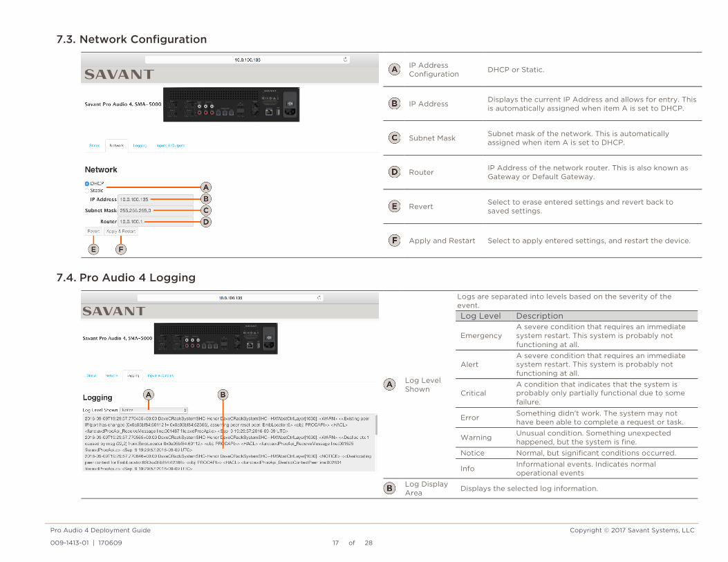
7.3. Network Configuration
IP Address Configuration DHCP or Static.
IP Address Displays the current IP Address and allows for entry. This is automatically assigned when item A is set to DHCP.
Subnet Mask Subnet mask of the network. This is automatically assigned when item A is set to DHCP.
Router IP Address of the network router. This is also known as Gateway or Default Gateway.
Revert Select to erase entered settings and revert back to saved settings.
Apply and Restart Select to apply entered settings, and restart the device.
7.4. Pro Audio 4 Logging
Log Level Shown
Logs are separated into levels based on the severity of the event. Log Level Description
Emergency A severe condition that requires an immediate system restart. This system is probably not functioning at all.
Alert A severe condition that requires an immediate system restart. This system is probably not functioning at all.
Critical A condition that indicates that the system is probably only partially functional due to some failure.
Error Something didn't work. The system may not have been able to complete a request or task.
Warning Unusual condition. Something unexpected happened, but the system is fine.
Notice Normal, but significant conditions occurred.
Info Informational events. Indicates normal operational events
Log Display Area Displays the selected log information.

Pro Audio 4 Deployment Guide Copyright © 2017 Savant Systems, LLC
009-1413-01 | 170609 18 of 28
7.5. Input & Output Configuration
Connector Type Analog Inputs: Stereo RCA, Digital Inputs (TosLink), Media Server.
Channel Trim
Adjusts the gain of the input from -10 dB to +10 dB.
Input List List of the inputs on the device.
I/O Connection Indicator
When an input is connected to an output, a line will appear between them showing that there is a connection. Inputs with no connection will have a black dot with no line. The dots can also be used to connect an input to an output. Simply click & hold the mouse on the dot next to the desired input and drag the line to desired output dot and release.
Output List List of the outputs on the device.
Output Channels
Stereo or Mono Clicking this field will toggle between the Stereo and Mono. Mono Summing: combines the left and right input signal into a single speaker channel output.
Delay
Adjustable delay per channel from 0 - 160ms.
Volume
Adjusts the volume level of the output channel. For speaker outputs, the possible adjustment range is -127dB to 18dB in 1dB increments. For Analog Out, the possible adjustment range is -48dB to 0dB in 1dB increments. No volume control is available for the Digital Out. Muting is available on all amplified speaker outputs and analog preamp output, independent from volume setting.
NOTE: There is no volume control in the Digital output. Any service from this output will require volume control on a different component.

Pro Audio 4 Deployment Guide Copyright © 2017 Savant Systems, LLC
009-1413-01 | 170609 19 of 28
8. Expansion Up to sixteen Pro Audio 4 units can be connected using MOTU AVB switchs; providing up to 96 zones of distributed audio (64 amplified zones and 32 preamp zones). Connecting two or more Pro Audio 4 units requires an AVB compliant switch.
NOTES:
– Prior to 8.4 there is a limit of three Pro Audio 4 units – Smart Hosts are limited to four Pro Audio 4 units
8.1. Blueprint Layout for 2 Devices with a MOTU AVB switch Blueprint layout for a system with two Pro Audio 4 devices

Pro Audio 4 Deployment Guide Copyright © 2017 Savant Systems, LLC
009-1413-01 | 170609 20 of 28
8.2. Adding the MOTU AVB Switch 1. From Blueprint Click Show Library 2. Search for MOTU.
3. Drag into a Shared Equipment zone. 4. Name the Device. 5. Place the MOTU switch in the layout window and make AVB connections.
The Pro Audio 4 Ethernet port must be connected to the MOTU AVB switch.
8.3. AVB Info in System Monitor Connections that output from the same device that they originate from will not display.
Examples: – Audio from device A that outputs from device B will display. – Audio from device A and outputting the same device will not display.
AVB Stations All AVB compliant Savant products will
display.
Connections All active AVB connections that originate
on the selected device

Pro Audio 4 Deployment Guide Copyright © 2017 Savant Systems, LLC
009-1413-01 | 170609 21 of 28
8.4. Blueprint Layout for 16 Devices with 5 MOTU AVB switches Blueprint layout for a system with sixteen Pro Audio 4 devices. This example only illustrates how to connect the MOTU AVB switches with the Pro Audio 4 units.
IMPORTANT INFO! – MOTU AVB switches must be daisy chained using AVB ports. – The annotation above shows MOTU 1 connected to MOTU 2, all MOTU switches are connected in this manner. – Only one of the MOTU AVB switches should be connected to the rest of the network using its uplink port.
Pro Audio 4 Deployment Guide Copyright © 2017 Savant Systems, LLC
009-1413-01 | 170609 22 of 28
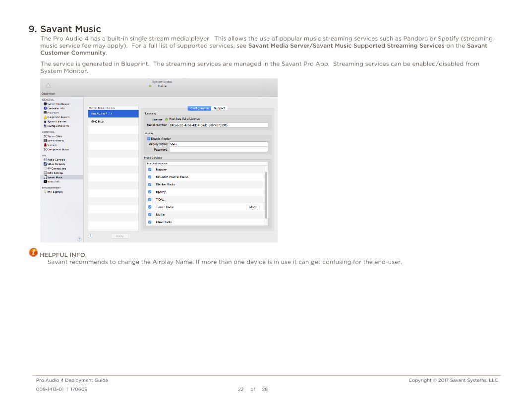
9. Savant Music The Pro Audio 4 has a built-in single stream media player. This allows the use of popular music streaming services such as Pandora or Spotify (streaming music service fee may apply). For a full list of supported services, see Savant Media Server/Savant Music Supported Streaming Services on the Savant Customer Community.
The service is generated in Blueprint. The streaming services are managed in the Savant Pro App. Streaming services can be enabled/disabled from System Monitor.
HELPFUL INFO: Savant recommends to change the Airplay Name. If more than one device is in use it can get confusing for the end-user.

Pro Audio 4 Deployment Guide Copyright © 2017 Savant Systems, LLC
009-1413-01 | 170609 23 of 28
Additional Information Refer to the following documents located on the Savant Customer Community for additional information.
– Savant Pro Audio 4 (Pro Audio 4) Quick Reference Guide – Savant Pro 8 App User Guide – Savant Media Server/Savant Music Supported Streaming Services
Pro Audio 4 Deployment Guide Copyright © 2017 Savant Systems, LLC
009-1413-01 | 170609 24 of 28
Appendix A: Network Requirements Savant requires the use of business class/commercial grade network equipment throughout the network to ensure the reliability of communication between devices. These higher quality components also allow for more accurate troubleshooting when needed.
Device Network Connections Connect all Savant devices to the same local area network (LAN) or subnet as the host. Savant recommends not implementing any type of traffic or packet shaping in your network topology for the Savant devices as this may interfere with performance.
AVB Requirements Savant requires a MOTU AVB Switch. The MOTU AVB switch should be an extension of the current network.
Managing IP Addresses To ensure that the IP Address will not change due to a power outage, a static IP Address or DHCP reservation should be configured. Savant recommends using DHCP reservation within the router. By using this method, static IP Addresses for all devices can be managed from a single UI avoiding the need to access devices individually.
Setting a Static IP Address Refer to the Appendix C. Setting DHCP Reservation Setting DHCP reservation varies from router to router. Refer to the documentation for the router to configure DHCP reservation.
Network Changes Savant recommends performing one of the following steps to refresh the IP connection after connecting to a new network, changing routers, or if the IP Address range is changed in the current router. This will reset any IP connection and ensure that the host is communicating with the network correctly.
– Cycle Power – Disconnect the Pro Audio 4 from the power source. – Wait 15 seconds and then reconnect.
– Hot Plug the Ethernet (LAN) Connection – Disconnect the Ethernet (LAN) connection from the controller. – Wait 15 seconds and then reconnect.

Pro Audio 4 Deployment Guide Copyright © 2017 Savant Systems, LLC
009-1413-01 | 170609 25 of 28
Appendix B: Document Revision History
009-1413-01 – June 2017 Section Update
6.3. Assigning Inputs and Outputs (I/Os) Updated Allowed Outputs information.
8. Expansion Updated the number of devices allowed.
8.4. Blueprint Layout for 16 Devices with 5 MOTU AVB switches
New Section.
9. Savant Music Updated information about streaming services.
Appendix D: DNS Server (Add Remove, Query) New Section.
009-1413-00 – November 2016 Section Update
All Initial releases of this Deployment Guide
Pro Audio 4 Deployment Guide Copyright © 2017 Savant Systems, LLC
009-1413-01 | 170609 26 of 28
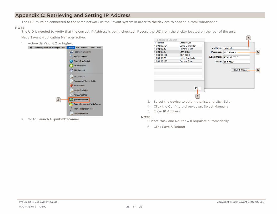
Appendix C: Retrieving and Setting IP Address The SDE must be connected to the same network as the Savant system in order to the devices to appear in rpmEmbSnanner.
NOTE: The UID is needed to verify that the correct IP Address is being checked. Record the UID from the sticker located on the rear of the unit.
Have Savant Application Manager active.
1. Active da Vinci 8.2 or higher.
2. Go to Launch > rpmEmbScanner
3. Select the device to edit in the list, and click Edit 4. Click the Configure drop-down, Select Manually 5. Enter IP Address
NOTE: Subnet Mask and Router will populate automatically.
6. Click Save & Reboot

Pro Audio 4 Deployment Guide Copyright © 2017 Savant Systems, LLC
009-1413-01 | 170609 27 of 28
Appendix D: DNS (Add, Remove, Query) Follow the instructions below to, add, remove, or query the DNS servers configured on the SMA-5000
1. Open a terminal window on a MacBook/SDE. 2. Enter ssh RPM@<IP Address of SMA-5000>
Example: ssh [email protected]
3. Once logged in, the commands below will add, remove, or query the DNS server(s) configured:
To add a DNS server: setDNSServer -add -address x.x.x.x <enter>
To remove a DNS server: setDNSServer -remove -address x.x.x.x <enter>
To query the DNS servers configured: setDNSServer <enter>
Terminal window will respond with the list of DNS servers as displayed below:
nameserver 8.8.8.8 nameserver 8.8.4.4
Pro Audio 4 Deployment Guide Copyright © 2017 Savant Systems, LLC
009-1413-01 | 170609 28 of 28
Important Notice
Disclaimer Savant Systems, LLC. reserves the right to change product specifications without notice, therefore, the information presented herein shall not be construed as a commitment or warranty.
Savant Systems, LLC. shall not be liable for any technical or editorial errors or omissions contained herein or for incidental or consequential damages resulting from the performance, furnishing, reliance on, or use of this material.
Patents Certain equipment and software described in this document is protected by issued and pending U.S. and foreign patents.
All products and services are trademarks or registered trademarks of their respective manufacturer.
Copyright This document contains confidential and proprietary information protected by copyright. All rights reserved. Copying or other reproduction of all or parts of this document is prohibited without the permission of Savant Systems.
Trademarks © 2017 Savant Systems, LLC. All rights reserved. Savant, Savant App, Savant Host, Now You Can, RacePoint Blueprint, Single App Home, TrueCommand, TrueControl, and the Savant logo are trademarks of Savant Systems, LLC.
AirPlay, Apple, AirPort Express, AirPort Extreme, Apple TV, Apple Remote Desktop, FireWire, iMac, iTunes, iPad, iPad mini, iPad Air, iPhone, MacBook, Mac and OS X are trademarks or trade names of Apple Inc. iOS is a trademark of Cisco®. Android, Google, Google Play, and other Google marks are trademarks of Google, Inc. Wi-Fi is a registered trademark of the Wi-Fi Alliance®. HDMI® is a trademark of HDMI Licensing, LLC. Autonomic® and TuneBridge® are registered trademarks of Autonomic Controls, Inc. MOTU® is a registered trademark of Mark of the Unicorn, Inc. Luxul® is a registered trademark of Luxul Wireless.
All other brand names, product names, and trademarks are the property of their respective owners.
Technical and Sales Support Savant Systems, LLC is dedicated to providing prompt and effective support in a timely and efficient manner.
– To contact Savant Support, access the Savant Customer Community and create a support case. – To contact Savant Sales, visit Savant.com and select Contact Us to locate a local sales representative in your area.