Embed Size (px)
Citation preview

1 © NEC Corporation 2018 IWLR 2018, Canberra, Australia
Satellite Laser Ranging Evaluation to Quasi-Zenith Satellite System
21st International Workshop on Laser Ranging
November 6, 2018
NEC Corporation
Ryoma Ishibashi
Outline
1. Overview of the Quasi-Zenith Satellite System(QZSS)
2. Improve orbit determination accuracy by SLR data
3. Future plans of the QZSS & Summary

1. Overview of the Quasi-Zenith Satellite System(QZSS)

4 © NEC Corporation 2018 IWLR 2018, Canberra, Australia
Quasi-Zenith Satellite System
▌MICHIBIKI No.1 was launched on Sep. 11, 2010. Afterwards, Government of Japan decided to make QZSS into a 4-satellite.
▌4-satellite constellation was established in 2017, and the operational service was started in Nov. 1st, 2018.
Quasi-Zenith Satellite System (QZSS)
Space Segment
Ground Segment
3 Quasi-Zenith Orbit (QZO) Satellites
1 Geostationary (GEO) Satellites
2 Master Control Station (MCS)
7 Uplink Station
22 Monitor Station

5 © NEC Corporation 2018 IWLR 2018, Canberra, Australia
QZSS Satellite(s) Overview
▌Block I-Q: MICHIBIKI No.1
⚫Lifetime: 10 years
⚫Orbit(QZO: Quasi-Zenith Orbit)
Semi-major Axis (a): 42164[km]
Eccentricity (e): 0.075/ Inclination (i): 41 deg
▌Block II-Q: MICHIBIKI No.2, 4
⚫Lifetime: 15 years+
⚫Orbit(QZO: Quasi-Zenith Orbit)
a, e, i: same as Block I-Q
▌Block II-G: MICHIBIKI No.3
⚫Lifetime: 15 years+
⚫Orbit(GEO: GeoStationary Orbit)
Longitude: E 127/ Latitude: 0
Block II-Q
Block II-G
S-band Antenna
Block I-Q

6 © NEC Corporation 2018 IWLR 2018, Canberra, Australia
QZSS Orbit
▌Japan Region
⚫ Over 20 degrees elevation (More than 2-QZS are available)
⚫ Over 60 degrees elevation (1-QZS is available)
▌QZSS Coverage Area at least one QZS is visible
4050
60
Equator
1 Geostationary satellite
GEO: on the Equator
QZO: “8 Letter” Orbit

7 © NEC Corporation 2018 IWLR 2018, Canberra, Australia
QZSS Satellite(s) Launch
▌MICHIBIKI Launched from Tanegashima space center.
No.1* No.2 No.3 No.4
launch Sep.11, 2010 Jun.1, 2017 Aug.19, 2017 Oct.10, 2017
Alert off Jun.21, 2011 Sep.15, 2017 Dec.18, 2017 Jan.12, 2018
* MICHIBIKI No.1 was transferred from JAXA to Cabinet Office on Mar. 2017.
[Block II-G: No.3] [Block II-Q: No.4] [No.3 launched]

8 © NEC Corporation 2018 IWLR 2018, Canberra, Australia
Typical Mission of QZSS
▌QZSS provides positioning-related service and messaging service.
▌Positioning-related service
⚫Satellite Positioning, Navigation & Timing Service (PNT)
The service to provide satellite positioning as same as US-GPS.
⚫Sub-meter Level Augmentation Service (SLAS)
The service to provide accurate positioning around 1-2 meters*.
⚫Centimeter Level Augmentation Service (CLAS)
The service to provide highly accurate positioning around 10 centimeters*.
* Ionosphere disturbance(fluctuations), multipath and others will affect the accuracy.
▌Messaging Service
⚫Sattellite Report for Disaster and Crisis Management (DC Report)
▌Positioning-related service supported by JCAB
⚫SBAS Service
To evaluate and improve the positioning accuracy by SLR data.
9 © NEC Corporation 2018 IWLR 2018, Canberra, Australia
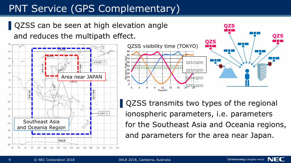
▌QZSS transmits two types of the regional
ionospheric parameters, i.e. parameters
for the Southeast Asia and Oceania regions,
and parameters for the area near Japan.
QZS
QZS
QZS
PNT Service (GPS Complementary)
▌QZSS can be seen at high elevation angle
and reduces the multipath effect.
Southeast Asia and Oceania Region
Area near JAPAN
・・・QZS1(QZO)
・・・QZS2(QZO)
・・・QZS4(QZO)
・・・QZS3(GEO)
QZSS visibility time (TOKYO)

2. Improve orbit determination accuracy by SLR data

11 © NEC Corporation 2018 IWLR 2018, Canberra, Australia
Tuning routine on QZSS operation
▌Accuracy evaluation using SLR data has helped modeling and parameter tuning of orbit determination.
Uplink Station
Monitor Stations
Master Control Station (MCS)
[Generation products]・Almanac products・Ephemeris products・Final products etc…
QZSS web sitehttp://qzss.go.jp/en
[QZSS archive data]・Final products etc…
[Broadcast data]・Almanac products・Ephemeris products etc…
QZSS
SLR Tracking by ILRS Network
・SLR data
[Parameter Tuning]Orbit estimation (SRP* parameter) tuning by SLR data.
Users
* SRP = Solar radiation pressure

12 © NEC Corporation 2018 IWLR 2018, Canberra, Australia
SLR visible stations for MICHIBIKI
▌SLR visible station for QZO (over 20 degrees elevation) ▌Number of ranging data
per SLR station
Name Number
YARL 667
SHA2 246
CHAL 106
BEIL 49
STL3 7
GMSL* 341From Jun.1, 2018. All QZS.
* GMSL is quarantine station (reference value). Data provided by JAXA.

13 © NEC Corporation 2018 IWLR 2018, Canberra, Australia
▌Time series graph of Number of SLR NPT data
▌We could obtain so many SLR data
⚫We thanks to the SRP parameter tunings by using these data, improve orbit estimation accuracy!! (detail is next slides)
SLR visible stations for MICHIBIKI
Daytime
Thank you for your cooperation!!

14 © NEC Corporation 2018 IWLR 2018, Canberra, Australia
SRP parameter tunings for MICHIBIKI by SLR(1/4)
▌Solar radiation pressure (SRP)
⚫SRP, which is a kind of force models for satellites, is key factor for precise orbit determination and estimation.
▌SRP models for orbit determination
⚫Analysis models
⚫Empirical models ✓: Adopted in MICHIBIKI
Depends on orbit position and β-angle. long-term fittings (parameter tuning) is required.
Gravity Geopotential, Third-Body potentials, etc…
It is not necessary to estimate the models. Can beapplied the same models for satellites. (For example, DE430).
Non-gravity SRP, AtomosphericDrag, etc…
It is necessary to estimate the model for each satellite (especially SRP).
Force models for satellite.

15 © NEC Corporation 2018 IWLR 2018, Canberra, Australia
SRP parameter tunings for MICHIBIKI by SLR(2/4)
▌CODE model (A kind of SRP empirical models)
⚫Define of the DBY coordinate system
▌Coordinate System
▌Acceleration
𝑎𝑠𝑟𝑝 = 𝑆 × (𝐷 𝑢 𝒆𝐷 + 𝑌 𝑢 𝒆𝑌 + 𝐵 𝑢 𝒆𝐵) × 10−9
𝐷 𝑢 = 𝐷0 + 𝐷𝑐𝑐𝑜𝑠𝑢 + 𝐷𝑠𝑠𝑖𝑛𝑢
Y 𝑢 = 𝑌0 + 𝑌𝑐𝑐𝑜𝑠𝑢 + 𝑌𝑠𝑠𝑖𝑛𝑢
𝐵 𝑢 = 𝐵0 + 𝐵𝑐𝑐𝑜𝑠𝑢 + 𝐵𝑠𝑠𝑖𝑛𝑢
⇒ We should optimize these 9 parameters (Dx, Bx, Yx) for each
satellites.
S = 𝐹𝑠ℎ𝑎𝑑𝑜𝑤 × 𝐴𝑈2/ 𝑟 − 𝑟𝑠2
F_shadow = Penumbra/umbra of earth/moonAU = Astronomical unit
16 © NEC Corporation 2018 IWLR 2018, Canberra, Australia
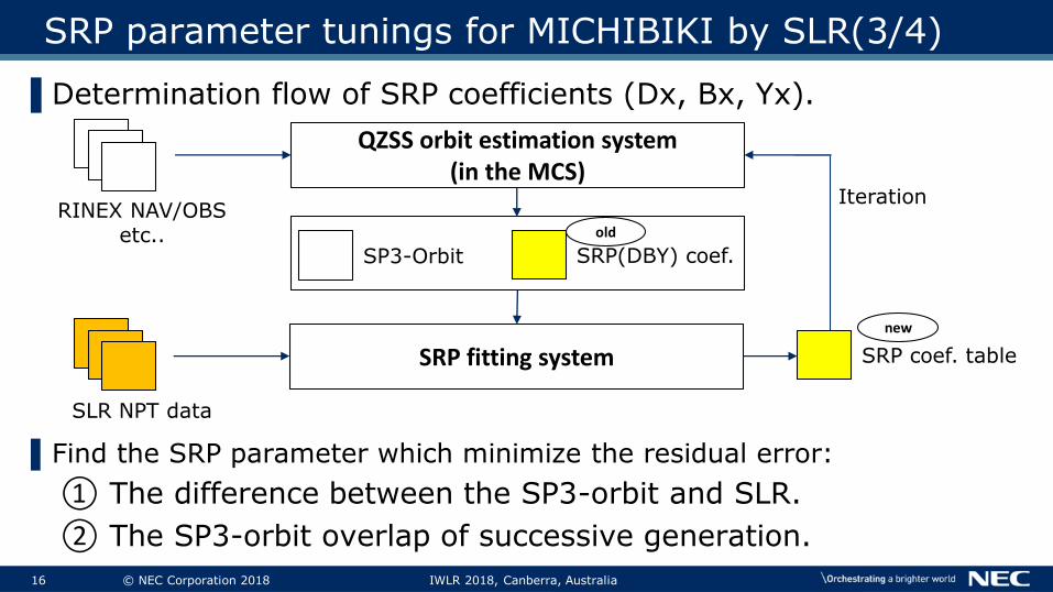
SRP parameter tunings for MICHIBIKI by SLR(3/4)
▌Determination flow of SRP coefficients (Dx, Bx, Yx).
▌Find the SRP parameter which minimize the residual error:
① The difference between the SP3-orbit and SLR.
② The SP3-orbit overlap of successive generation.
QZSS orbit estimation system(in the MCS)
RINEX NAV/OBSetc..
SP3-Orbit SRP(DBY) coef.
SRP fitting system
SLR NPT data
SRP coef. table
new
Iteration
old

17 © NEC Corporation 2018 IWLR 2018, Canberra, Australia
Parameter tuning for MICHIBIKI by SLR(4/4)
▌Result of SRP parameter fitting for MICHIBIKI No.2 (Offline).
Before SRP fitting (old SRP coef.) After SRP fitting (new SRP coef.)
SP3 Orbit-overlap: 0.30m (rms) SP3 Orbit-overlap: 0.17m (rms)
Residuals (SP3-overlap and SLR): 0.46m (rms)
Residuals (SP3-overlap and SLR): 0.37m (rms)

18 © NEC Corporation 2018 IWLR 2018, Canberra, Australia
▌Accuracy evaluation of all QZS products by SLR data.
▌SLR residuals of No.2 and No.4 was improved by thanks to SRP fitting. We will carry out continuous tuning for Other QZS.
▌We appreciate ILRS’ laser ranging activities, and needcontinuous support by ILRS for QZS’ accuracy improvement.
Evaluation for MICHIBIKI
No.1
No.2
No.3
No.4
[Stations]BEIL, CHAL, SHA2, STL3, YARL, GMSL
SRP fitting of MICHIBIKI No.2 and No.4
Add new SRP coef. for No.2 and No.4.

3. Future plans of the QZSS & Summary

20 © NEC Corporation 2018 IWLR 2018, Canberra, Australia
Future plans of QZSS
▌4-satellite constellation of QZSS has just started on this November. It will be established 7-statellite constellation in 2023.
Japanese FY 2018 2019 2020 2021 2022 2023~
QZSS4-satellite
constellation
QZSS7-satellite
constellation
From Nov.1
Operational service since 2018 by Govt. of Japan (CAO)
No.1 replacement
Service Development/Launch
Additional 3 satellites
Trial Service
21 © NEC Corporation 2018 IWLR 2018, Canberra, Australia
Summary
▌The 4-satellites constellation was established by the end of 2017 and the full operational service has started on this Nov. 1st.
▌QZSS achieved high-performance positioning results as GPS complemental system.
▌The evaluated results of SRP fittings by SLR data is quite a good result. QZSS wants continuous cooperation by ILRS.
▌We will start the development of 7-satellite constellation, and it will be established within 2023.
▌Acknowledgements
We would like to express the special thanks to ILRS’ cooperation.

22 © NEC Corporation 2018 IWLR 2018, Canberra, Australia
Thank you for your attention.
For more information, please visit our web sitehttp://qzss.go.jp/en


24 © NEC Corporation 2018 IWLR 2018, Canberra, Australia
Laser ranging for QZS
▌All QZS equipped the LRA for laser-ranging. Property information is below.
▌Location of LRA optical center
▌Envelope (same as all QZS)
⚫400[mm] x 400[mm]x100[mm]
▌Number of corner cube reflector
⚫56 (7 rows x 8 lines)
LRA
Location of LRA(MICHIBIKI No.2)
Laserretro-reflectorarray (LRA)

25 © NEC Corporation 2018 IWLR 2018, Canberra, Australia
Signal of QZSS
1st Satellite 2nd-4th Satellite
Block I-Q Block II-Q Block II-G
L1C/A
1575.42MHz
Positioning(PNT) ✓ ✓ ✓L1C Positioning(PNT) ✓ ✓ ✓
L1SAugmentation(SLAS) ✓ ✓ ✓
Message Service ✓ ✓ ✓L2C 1227.60MHz Positioning(PNT) ✓ ✓ ✓L5
1176.45MHzPositioning(PNT) ✓ ✓ ✓
L5SAugmentationExperimental
N/A ✓ ✓
L6D1278.75MHz
Augmentation(CLAS) ✓ ✓ ✓L6E Experimental N/A ✓ ✓L1Sb 1575.42MHz Augmentation N/A N/A ✓S-band 2GHz band Message Service N/A N/A ✓
▌In addition to the positioning signals (GPS complementation), QZSS transmits the augmentation signals and the message/experimental signals.
26 © NEC Corporation 2018 IWLR 2018, Canberra, Australia
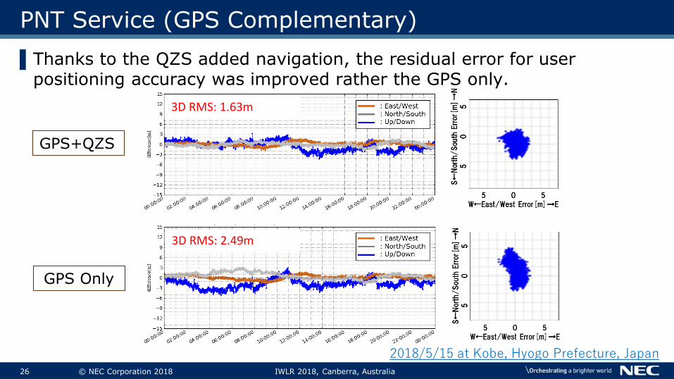
PNT Service (GPS Complementary)
▌Thanks to the QZS added navigation, the residual error for user positioning accuracy was improved rather the GPS only.
GPS+QZS
3D RMS: 1.63m
GPS Only
3D RMS: 2.49m
2018/5/15 at Kobe, Hyogo Prefecture, Japan