Embed Size (px)
Citation preview

Paper ID #10095
Satellite Design for Undergraduate Senior Capstone
Mr. Joseph Thomas Emison, Taylor University
Joseph Emison is a Senior Engineering Physics Major at Taylor University. From spring 2013 to presenthe has served as the Project Engineer and VLF/E-Field Sensing Lead of the Taylor University ELEO-Satnanosatellite in the Air Force Research Lab’s University Nanosatellite Program competition. Joseph willgraduate in December 2014 and eager to continue doing research, whether in graduate school or industry.
Miss Kate Yoshino, Taylor University
Kate Yoshino is a junior at Taylor University studying Engineering Physics. Currently, she serves as theProject Manager for Taylor University’s Extremely Low Earth Orbit Nanosatellite (ELEO-Sat). Kate isresponsible for team management, stakeholder communication, schedules, and programmatic budgeting.Additionally, she is responsible for community and educational outreach and the development of one ofELEO’s primary sensors (Langmuir Probe).
Mr. Stephen Edward Straits, Taylor University
STEPHEN STRAITS is an undergraduate student in Engineering Physics at Taylor University, with afocus on mechanical and systematic engineering. He is currently the Lead Mechanical Engineer forELEO-Sat and has contributed to the design of TSAT and GEARR-Sat. He will be graduated May 2014.Email: stephen [email protected]
Dr. Hank D. Voss, Taylor University
Dr. Hank D. Voss received his Ph.D. in Electrical Engineering from University of Illinois in 1977.He thenworked for Lockheed Palo Alto Research Laboratories prior to coming to Taylor University in 1994. Heis currently a Professor of Engineering and Physics at Taylor University. Some of the courses that he reg-ularly has taught include Principles of Engineering, Intro to Electronics, Statics, Advanced Electronics, Jr.Engineering Projects, FE Review, Control Systems, Fundamentals of Space Flight Systems, Astronomy,and Sr. Capstone Sequence.
He enjoys mentoring undergraduate students in aerospace, sensors, and energy-related research projects.Some of the research areas include spacecraft nano-satellite technologies, satellite payload instrumenta-tion, High Altitude research Platform (HARP) experiments, wave particle interactions in space, space-flight X-ray imagers, construction and renewable energy engineering and architecture, and philosophy ofscience. Dr. Voss has worked as PI on many NASA, Air Force, Navy, NSF, and DOE research grants andhas published over 120 scientific papers.
c©American Society for Engineering Education, 2014

Satellite Design for Undergraduate Senior Capstone

Abstract
This paper demonstrates the educational value of satellite design in an engineering
capstone course. Taylor University engineering capstone students participate in the Air Force
Research Laboratory’s (AFRL) University Nanosatellite Program (UNP) competition to design
and deliver a small satellite (nanosatellite), which will accomplish a mission with real-world
significance. Undergraduate educational merits and assessment are discussed and demonstrated
through overwhelmingly positive feedback from alumni. The capstone course focuses on
developing capable engineers with ABET a-k 1 proficiency. According to the Air Force Research
Laboratory, the objective of the UNP competition is to “train tomorrow’s space professionals by
providing a rigorous, two-year, concept-to-flight-ready spacecraft competition for U.S. higher
education institutions and to enable small satellite research and development (R&D), integration
and flight test” 15
. UNP and engineering capstone design processes are also detailed. Through
UNP and the senior engineering capstone class, students experience end-to-end development of a
project with real-world application in the aerospace industry. The project promotes creativity and
develops skilled engineers.
Figure 1: Taylor University Extremely Low Earth Orbit nanosatellite (ELEO-Sat) –
background photo take from high altitude balloon at SHOT Workshop 2013
Introduction
This introduction provides a brief overview of the content of the paper. Information on
the University Nanosatellite Program, the project mission, and the influence of the project on
undergraduate education is detailed in the background section. Further assessment of the
educational value of the program may be found in the Assessment section. Taylor University and
UNP design processes are explained in the Design section.
Background
The Extremely Low Earth Orbit nanosatellite (ELEO-Sat) (see Figure 1) is an
undergraduate senior design project in an engineering capstone course at Taylor University. The
project is made possible through the University Nanosatellite Program (UNP). The development
of a satellite provides a hands-on learning environment that challenges students and encourages
development of new skills. The benefits of participation in UNP are shared by hundreds of
undergraduate and graduate students across the country.
University Nanosatellite Program
The University Nanosatellite Program (UNP) is an educational program focused on
developing students by exposing them to professional engineering experiences while giving
universities an opportunity to contribute to innovative scientific research projects. The aim of
UNP is for “students to learn the tough lessons about satellite design by building one
themselves” 3. UNP was created to focus on three key areas, which are education, technology,
and university development. This is demonstrated in each two year UNP cycle by the
involvement of 10-12 universities whose individual projects exhibit advancements in education
and technology.
Taylor University’s involvement in the AFRL program began with TEST, a
microsatellite, in UNP-3 and now continues in UNP-8 with ELEO-Sat. UNP provides many
opportunities for each university and its students to glean vital, detailed knowledge about
designing functional aerospace systems. The AFRL features Expert Area Teleconferences, or
EATs, where field experts teach key aspects of the engineering process and subsystem design.
Examples of EAT topics include configuration management, attitude determination and control,
concept of operations, thermal control, and structural design.
Moreover, learning is encouraged through attendance to conferences and workshops such
as the SmallSat Conference, the Student Hands On Training (SHOT) Workshop, and the
CubeSat Developers’ Workshop. The SHOT Workshop and SmallSat Conference were held
during the summer of 2013; more than half of the Taylor University team attended one or both.
The focus of the SHOT workshop is to teach small teams from each university the skills
necessary to assemble a balloon satellite, which is a low-level satellite prototype for a high
altitude balloon launch. The SmallSat conference introduced students to new small satellite
technology and developments. Those who attended received an excellent learning experience
regardless of their engineering background. The next CubeSat Developers’ Workshop will be in
April 2014.
UNP also provides mentorship for each team. Each UNP team is assigned a point of
contact (PoC) at the AFRL. The point of contact can provide technical guidance for the design
process and connect a team with expert contacts for further assistance. Contacts provided by a
PoC sometimes become additional mentors on the project.
Mission Overview
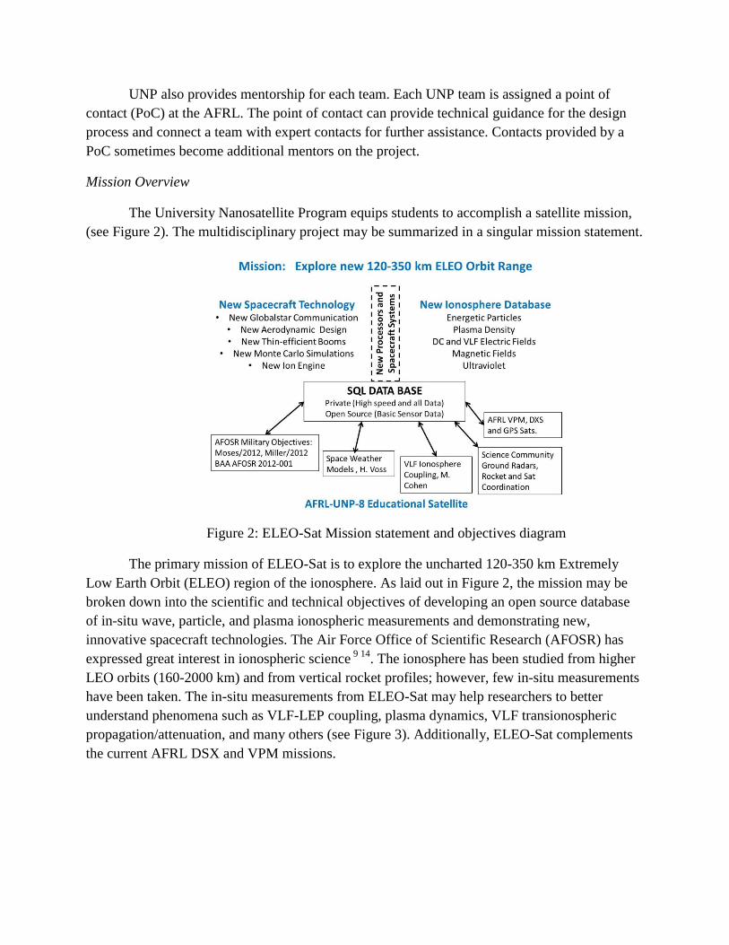
The University Nanosatellite Program equips students to accomplish a satellite mission,
(see Figure 2). The multidisciplinary project may be summarized in a singular mission statement.
Figure 2: ELEO-Sat Mission statement and objectives diagram
The primary mission of ELEO-Sat is to explore the uncharted 120-350 km Extremely
Low Earth Orbit (ELEO) region of the ionosphere. As laid out in Figure 2, the mission may be
broken down into the scientific and technical objectives of developing an open source database
of in-situ wave, particle, and plasma ionospheric measurements and demonstrating new,
innovative spacecraft technologies. The Air Force Office of Scientific Research (AFOSR) has
expressed great interest in ionospheric science 9 14
. The ionosphere has been studied from higher
LEO orbits (160-2000 km) and from vertical rocket profiles; however, few in-situ measurements
have been taken. The in-situ measurements from ELEO-Sat may help researchers to better
understand phenomena such as VLF-LEP coupling, plasma dynamics, VLF transionospheric
propagation/attenuation, and many others (see Figure 3). Additionally, ELEO-Sat complements
the current AFRL DSX and VPM missions.

Figure 3: Diagram of mission location
As a part of its exploratory mission, ELEO-Sat will demonstrate new, innovative
technologies for Low Earth Orbit (LEO), 160-2000 km, satellites. Technology objectives connect
to AFOSR relevance 14
. A Globalstar satellite-to-satellite communication link will allow global
throughput for LEO orbit satellites and potentially allow continuous command capability. The
new communications link will be flight tested for the first time in spring 2014 aboard TSAT and
GEARR-Sat, predecessors of ELEO-Sat. Uniquely, ELEO-Sat will rely primarily on passive
attitude control, including a gravity gradient and an aerodynamic control loop, and will utilize an
aerodynamic form factor to increase its lifetime in ELEO, where drag forces are high 8. In-house
developed Monte Carlo simulations will empower preflight analysis of drag effects 8 and
performance of a new ion engine.
The objective of education (shown at the base of Figure 2) expresses the educational
foundation of UNP. The educational experience of building a nanosatellite is one of the major
underlying purposes set forth by the UNP. Thus, the experience greatly contributes to student
learning.
Undergraduate Educational Merits
The ELEO-Sat project provides a unique opportunity for student learning through a real-
world design experience. At the end of the two year UNP cycle students supply a satellite to the
Air Force Research Laboratories. Hands on satellite development helps students develop
important career skills such as teamwork, systems engineering, and integration. Students learn

the importance of deadlines and scheduling throughout the design and development process. A
high expectation level encourages students to produce quality work and to present it with
competency at design reviews with the Air Force and industry professionals. The process
provides insight into the professional world and teaches students to develop individual
subsystems within a team.
Team members come from a wide range of disciplines. Students from each of Taylor
University’s engineering majors, which include Engineering Physics, Computer Engineering,
Environmental Engineering, and Systems Engineering, participate in the same senior capstone
course. Junior and underclassman engineering students are also involved in the project, working
on smaller subsystems or tasks, in order to mitigate risk presented by student turnover upon
graduation. Students in majors including Mathematics, Physics, Business, Accounting,
Elementary Education, and Computer Science also participate voluntarily in the senior
engineering project under the leadership of the faculty and engineering students. For example, an
undergraduate mathematician developed and calibrated Monte Carlo simulations of free-
molecular aerodynamics to determine drag effects in ELEO orbits. An example of non-technical
involvement is business students who organized events to promote campus awareness of ELEO-
Sat. Moreover, the senior capstone course involves local high school students considering STEM
careers through outreach programming including participation in high altitude balloon projects.
Similarly, the project provides outreach opportunities to local elementary schools, using space
science curriculums developed by Taylor University elementary education majors. Working on
projects like ELEO-Sat equips students from many disciplines with skills they need for the
future. Collaboration between non-capstone students, professors, and engineering students
benefits student learning as a whole.
Design Process
The design process in the engineering capstone course facilitates end-to-end design and
traces ABET a-k objectives. Figure 4, a diagram adapted from Ford-Coulston 2008, illustrates
how the engineering capstone course connects the ABET a-k objectives 1, listed below, to an
intentional, directed, thoughtful, and sustainable design process. The curriculum emphasizes
each of the four design processes at different points in the course as indicated by the associated
dates. The multiple node lines in the decagon represent many feedback and discussion pathways.
The black abbreviations underneath the process headings indicate documents required within
each phase and the highlighted outcomes indicate ABET a-k objectives linked to each process
and stage of the design. Subsequent subsections in the Design Process section indicate
connections to the Figure 4 design process by identifying corners of the decagon e.g. “Figure 4 –
2 Brainstorming, Research, Scope.”

Figure 4: Capstone design process
ABET A-K Objectives
Students are expected to possess or develop:
a. an ability to apply knowledge of mathematics, science and engineering
b. an ability to design and conduct experiments, as well as to analyze and interpret data
c. an ability to design a system, component, or process to meet desired needs within realistic
constraints such as economic, environmental, social, political, ethical, health and safety,
manufacturability, and sustainability
d. an ability to function on multidisciplinary teams
e. an ability to identify, formulate, and solve engineering problems
f. an understanding of professional and ethical responsibility
g. an ability to communicate effectively (3g1 orally, 3g2 written)
h. the broad education necessary to understand the impact of engineering solutions in a
global, economic, environmental, and societal context
i. a recognition of the need for, and an ability to engage in life-long learning
j. a knowledge of contemporary issues
k. an ability to use the techniques, skills, and modern engineering tools necessary for
engineering practice.
Additionally, the design process is guided by UNP standards for design reviews. Figure 5 and

6, below, illustrate the electrical and mechanical design processes, respectively 13
. Review
deliverables, e.g. concept, breadboard, brass board, are expected at the reviews indicated, e.g.
SRR, PDR, CDR.
Figure 5: UNP Electrical design process

Figure 6: UNP Mechanical design process
UNP review deliverables include required documentation. Deliverables for the Flight
Competition Review (FCR) include:
● Assembly Procedures
● Block Diagrams
● CAD of Spacecraft
● Concept of Operations
● Data Budget
● Document Tree
● EMC/EMI Mitigation Design
● Experiment Plan
● Ground Support Design
● Interface Control Documents
● Personnel Budget
● Power Budget
● Press Related Information
● Pressure Profile
● Proof of Licensing
● Protection Plan
● Quad Chart
● Radiation Mitigation Design
● Requirements Verification Matrix
● Schedule
● Link Budget
● Mass Budget
● Master Equipment List
● Materials List
● Mechanical Drawing Package
● Mission Overview
● Silver Board Test Results
● Software
● Structural Analysis
● System Functional Test Results
● Thermal Analysis
The UNP User Guide describes the documentation deliverables in depth 12
. Work on the design
deliverables is expounded upon in subsequent subsections of the design process.
Design Challenges
In order to achieve mission success, students must address real-world spacecraft design
challenges. The multidisciplinary nature of the design challenges is one of the reasons why a
multidisciplinary team is so important. Spacecraft design requires electrical, electromagnetic,
mechanical, thermal, embedded systems, and systems engineering skills.
The wide variety of environmental factors is among the most difficult and critical
challenge to overcome. Radiative heat transfer and internal heat production set the nominal
thermal environment inside the spacecraft, which must be maintained within operating
temperature ranges. The satellite must additionally be able to survive the high intensity vibration
and stress experienced in the launch environment. Students design to wide margins to account
for uncertainty. For example, since the satellite will be a secondary payload, the design must
address uncertainty in launch date and orbit, which are not guaranteed and may greatly influence
the ambient thermal environment and battery charging cycle. Moreover uncertainty in the launch
date brings new factors into play such as mechanism creep. The design must also account for the
high drag forces experienced in low earth orbit, which may decrease satellite lifetime and cause
spacecraft rotation.
Many other design factors are considered in satellite design. Subsystems must be
spatially allocated to eliminate mechanical crowding, simplify cable routing, and mitigate the
risk of electromagnetic interference between subsystems. Other factors are captured in design
budgets (see documentation requirements for FCR above). Students respond to uncertainty in
design budgets by providing margins of at least 20% in the early design phases.
Spacecraft Overview
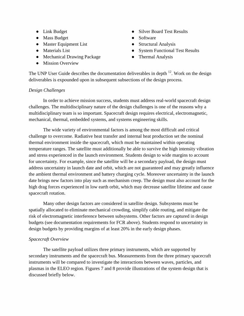
The satellite payload utilizes three primary instruments, which are supported by
secondary instruments and the spacecraft bus. Measurements from the three primary spacecraft
instruments will be compared to investigate the interactions between waves, particles, and
plasmas in the ELEO region. Figures 7 and 8 provide illustrations of the system design that is
discussed briefly below.
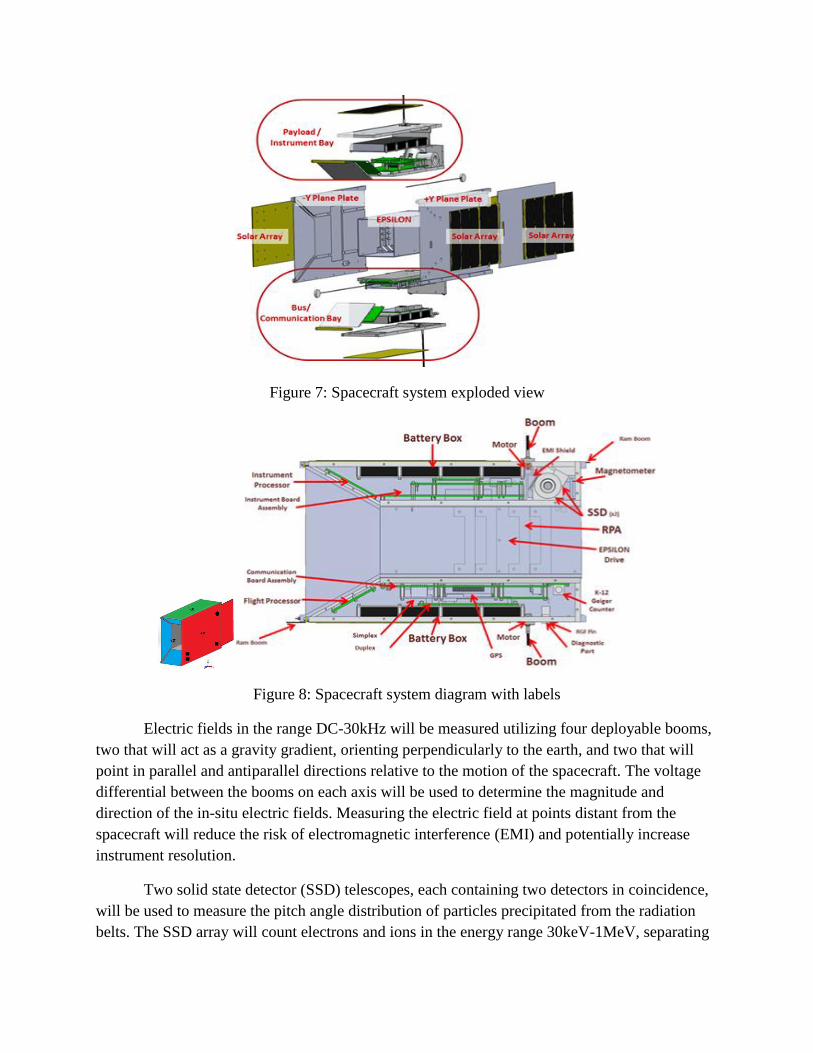
Figure 7: Spacecraft system exploded view
Figure 8: Spacecraft system diagram with labels
Electric fields in the range DC-30kHz will be measured utilizing four deployable booms,
two that will act as a gravity gradient, orienting perpendicularly to the earth, and two that will
point in parallel and antiparallel directions relative to the motion of the spacecraft. The voltage
differential between the booms on each axis will be used to determine the magnitude and
direction of the in-situ electric fields. Measuring the electric field at points distant from the
spacecraft will reduce the risk of electromagnetic interference (EMI) and potentially increase
instrument resolution.
Two solid state detector (SSD) telescopes, each containing two detectors in coincidence,
will be used to measure the pitch angle distribution of particles precipitated from the radiation
belts. The SSD array will count electrons and ions in the energy range 30keV-1MeV, separating
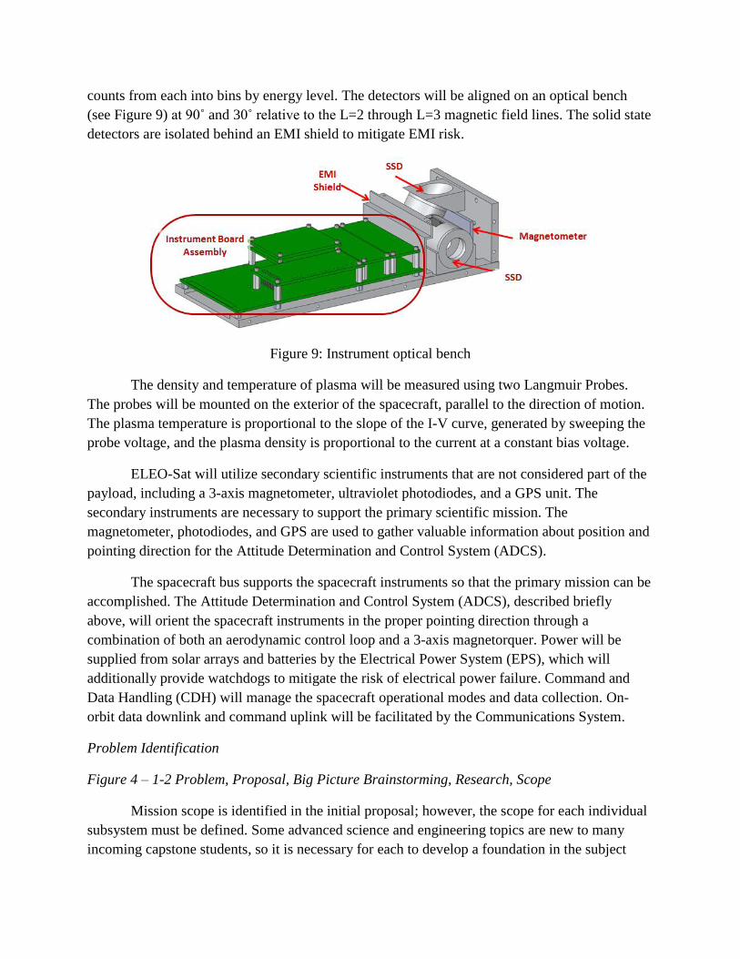
counts from each into bins by energy level. The detectors will be aligned on an optical bench
(see Figure 9) at 90˚ and 30˚ relative to the L=2 through L=3 magnetic field lines. The solid state
detectors are isolated behind an EMI shield to mitigate EMI risk.
Figure 9: Instrument optical bench
The density and temperature of plasma will be measured using two Langmuir Probes.
The probes will be mounted on the exterior of the spacecraft, parallel to the direction of motion.
The plasma temperature is proportional to the slope of the I-V curve, generated by sweeping the
probe voltage, and the plasma density is proportional to the current at a constant bias voltage.
ELEO-Sat will utilize secondary scientific instruments that are not considered part of the
payload, including a 3-axis magnetometer, ultraviolet photodiodes, and a GPS unit. The
secondary instruments are necessary to support the primary scientific mission. The
magnetometer, photodiodes, and GPS are used to gather valuable information about position and
pointing direction for the Attitude Determination and Control System (ADCS).
The spacecraft bus supports the spacecraft instruments so that the primary mission can be
accomplished. The Attitude Determination and Control System (ADCS), described briefly
above, will orient the spacecraft instruments in the proper pointing direction through a
combination of both an aerodynamic control loop and a 3-axis magnetorquer. Power will be
supplied from solar arrays and batteries by the Electrical Power System (EPS), which will
additionally provide watchdogs to mitigate the risk of electrical power failure. Command and
Data Handling (CDH) will manage the spacecraft operational modes and data collection. On-
orbit data downlink and command uplink will be facilitated by the Communications System.
Problem Identification
Figure 4 – 1-2 Problem, Proposal, Big Picture Brainstorming, Research, Scope
Mission scope is identified in the initial proposal; however, the scope for each individual
subsystem must be defined. Some advanced science and engineering topics are new to many
incoming capstone students, so it is necessary for each to develop a foundation in the subject

matter before identifying subsystem scope in a Project Scope Statement. The learning process is
accomplished through both student interaction with the Primary Investigator (PI) and
independent research. Evaluation of Project Scope Statement documents is conducted by the PI
and other supervising faculty.
Requirements Analysis
Figure 4 – 3 Requirements Specification
After students have gained a thorough understanding of their projects, the student scopes
are broken down into requirements. Students use Ford-Coulston, Design for Electrical and
Computer Engineers as a primary tool for learning requirements analysis. IEEE std. 1233-1998
states that requirements must be abstract, verifiable, unambiguous and traceable 4. Ford-Coulston
adds that requirements must be realistic 4. Although the literature is intended specifically for
electrical and computer engineers, the design process is relevant to each of the engineering
disciplines represented on the project. The UNP User Guide specifies that requirements should
be captured in a Requirements Verification Matrix (RVM) 12
. The flow-down of requirements in
the RVM (see Figure 10) ensures that all requirements are mission relevant.
Figure 10: Requirements flow-down
The flow-down of the requirements is captured in sources either from within the RVM or
from outside documents (see Table 1). UNP satellites must additionally comply with UNP and
California Polytechnic State University (Cal Poly) requirements (see Table 2). Each requirement
is initially assigned one of four verification methods: inspection, analysis, demonstration, and
test 6. Test and analysis verifications are given short descriptions in the RVM and specific
procedures are determined at the beginning of testing phases.
Ref Requirement Source Verification

ThEEF-
1
ThEEF shall measure E-fields over the
frequencies DC-30kHz
Instrument requirements
- data budget document
Test:
calibration
ThEEF-
2
ThEEF shall have an equivalent noise
input of less than 1 mV/m
Instrument requirements
- data budget document
Test:
calibration
ThEEF-
3
ThEEF Will measure E-fields with
magnitudes up to 2.5 V/m
Instrument requirements
- data budget document Demonstration
ThEEF-
4
ThEEF shall measure E-fields on two
axes Mission Overview Inspection
Table 1: RVM Sample - ThEEF Instrument Subsystem Requirements
Ref Requirement Source Verification
MS-1 The SmallSat shall be designed to
withstand the launch and on-orbit
environments of the launch vehicle
without failure, leaking fluids, or
releasing anything.
UNP-2, CP-7, CP-8 Test: vibration
table, thermal
vacuum
MS-2 The SV shall be designed using the
MAC curve in Figure 7 in section
6.3.1 of the NS-8 User Guide
UNP-3 Test: vibration
table, thermal
vacuum
MS-3 Factor of safety to be used are 2.0 for
yield and 2.6 for ultimate for
structural design and analysis
UNP-4 Analysis:
SolidWorks
simulation
MS-4 The SV volume shall depressurize
safely at a rate of 0.5 psi/sec
UNP-5 CP-4, CP-5 Test: thermal
vacuum
MS-5 The SmallSat shall be designed to
withstand the launch vehicle shock
environment as shown in Table A and
Figure A (Table A and Figure A are
available in actual RVM)
UNP-6 Test: vibration
table
Table 2: RVM Sample - Mechanical chassis requirements
Concept Generation

Figure 4 – 4 Concept Model Generation
Requirements are synthesized into design concepts, which are most commonly
represented on a block diagram level. Figure 11 exhibits a student’s concept for an instrument
processor subsystem. The appropriateness of project scope, requirements, and concepts are
assessed by the PI, other supervising faculty, and peers in concept reviews.
Figure 11: Instrument processor subsystem concept
Evaluation of real-world design tradeoffs is critical for determining which concepts will
be implemented in the design phase. Technical Readiness Level (TRL) and risk are two of the
primary judging criteria in UNP; thus, design trade-offs are evaluated accordingly using TRL
charts (see Figure 12) and Likelihood-Consequence (L-C) Charts (see Figure 13) 13
. TRL charts
indicate overall system and subsystem progress measured by readiness of review deliverables.
Moreover, TRL charts may be used to identify critical paths for project work. Subsequently,
design trade-offs are evaluated on the basis of adherence to the critical path.

Figure 12: Bus systems TRL Chart from Preliminary Design Review
An L-C Chart displays how the likelihood (y-axis) of a risk and the resulting
consequences (x-axis) relate to the overall risk (color, green is low risk). Figure 13 also identifies
the design risks corresponding to numbers in the L-C Chart. The expectation is that risks are
unambiguously identified in a manner understandable to reviewers who may not be familiar with
the project.
Figure 13: L-C Chart for 3U to 6U size Design change from Critical Design Review
L-C and TRL charts encourage thoughtful design and demonstrate effective preparation
to UNP judges. Other methods of evaluation are used as appropriate. For example, along with L-

C Chart analysis (see Figure 13), students used a cost/benefit analysis when evaluating a design
change from a 3U size (10x10x34cm) to a 6U size (10x20x34cm) 2 (see Figure 14).
Figure 14: 3U to 6U Design Change Graphic from Critical Design Review
Design
Figure 4 – 5 Design, Prototype, Analysis
When concepts are approved, students begin the iterative process of design, prototype,
and analysis. Applying undergraduate learning to hands-on experience is one of the most
valuable elements of UNP. Students apply a variety of tools to the design of their subsystems.
Mechanical designs are implemented in SolidWorks and MatLab. SolidWorks Simulation
Premium is capable of performing multiple analyses for required deliverables including pressure
profiles, static loading, and vibration simulations. Figure 15 illustrates the exaggerated results of
mode frequency testing.
Figure 15: SolidWorks analysis of chassis vibration modes (Exaggerated)
SolidWorks is also used for 10+ node thermal analysis. Thermal models with fewer than

10 nodes are implemented in MatLab Simulink because it allows students to fine tune
assumptions used in the analysis. For the same reason, lower node Simulink models are used to
verify higher node SolidWorks models. MatLab has other useful plugins including the CubeSat
Toolbox which was used to determine solar power gathered over a typical ELEO orbit (see
figure 16).
Figure 16: Solar power simulation in MatLab CubeSat Toolbox
After initial analysis in SolidWorks, mechanical models are fabricated on a BFD
3DTouch 3D-printer. Prototyping the mechanical model facilitates development of assembly
procedures and cable harnessing (see Figure 17).
Figure 17: 3-D printed chassis
Electrical designs are tested on breadboards and analyzed in LTspice or PSpice. Success

with preliminary analysis and testing is channeled into schematic and board development in
Eagle CAD. Printed circuit boards (PCBs) are subsequently fabricated on an LKPF ProtoMat
S63 PC Mill. Figure 18 exhibits a design (left) and prototype (right) of the instrument processor
board, which was developed from the concept in Figure 11.
Figure 18: Instrument Processor Eagle CAD Layout and PCB
Electrical brass boards are then tested and calibrated. Figure 19 (left) exhibits an
oscilloscope screen shot of the response of a Solid State Detector (SSD) to a calibration pulse.
Similarly, Figure 19 (right) displays calibration curves of the VLF search coil in response to an
applied magnetic field.
Figure 19: SSD Pulse Scope Shot (Left) and VLF Search Coil Calibration Curves (Right)
System Integration
Figure 4 – 6-8 Parts, Construction, System Integration, System Test
After all subsystems are designed, they must be integrated into a functioning system.
Interfaces are the most important place to improve a design and the easiest place to make

mistakes. Students learn many of their lessons the hard way on interfacing. The High Altitude
Research Platform (HARP) is Taylor University’s high altitude balloon program and a primary
testing method for ELEO-Sat (see Figure 20). The near-space environment that HARP balloons
encounter is similar to the thermal-vacuum and vibration testing that the satellite will undergo
before acceptance. In-house tools, including a 3D-printer, a PC-mill, and a laser cutter are
utilized for fabrication of spacecraft prototypes. By participating in HARP launches, students
learn project engineering and communication skills through team integration and assembly.
Figure 20: Integrated ELEO-Sat balloon satellite.
Even though each sub system is fully functioning in bench testing phases, bringing them
together reveals many undiscovered problems, not only for individual subsystems but also for the
overall system. These problems, both electrical and mechanical, are only discovered once
everything is assembled.
Delivery & Maintenance
Figure 4 – 9-10 Delivery, Acceptance, Maintenance, Upgrade
If the team successfully completes the Flight Competition Review (FCR) it will proceed
to the next stage of UNP, where the team will continue the development of the satellite alongside
the AFRL. The second phase of the program continues until the satellite is flight ready.
Maintenance and upgrade, if necessary, occur after the acceptance of the satellite.
Assessment

Establishing an efficient design process through the capstone class requires assessment of
the program to determine what works and what does not. A good capstone class encourages
vision and challenge while capturing imagination. Students should be encouraged, but much is
expected from them. When there is strong team spirit, trust, and vision in a capstone project, the
potential for learning is high. Figure 4 helps define the ABET outcomes and the design process
sequence that is used for development of each student’s subassemblies and the integration of the
complete and tested satellite. It can be very hard for students to appreciate the many feedback
and feed-forward lines in the classic design process between decagon vertices and the ABET
outcomes a-k (see Figure 4). The ABET outcomes are reinforced and developed continuously
throughout the full design cycle.
The formal student documents required for evaluation and assessment include the
following: POP (Project Big Picture Overview Proposal), PSS (Project Scope Statement), PRD
(Product Requirements Document), TDD (Team Definition Document), SOW (Statement of
Work/Work Breakdown), NAS (NASA CubeSat Requirement Documents), PSD (Product
Specification Document), PDR (Preliminary Design Document & Review), CDR (Critical
Design Document & Review), PPD (Pre-Procurement Review, WBS, Schedule), ASEE1
(Submit ASEE Draft Papers), HARP (High Altitude Balloon Research Platform), ASEE2
(Submit final Papers and Posters), SCR (ELEO-Sat System Concept Review), SRR (ELEO-Sat
Systems Requirements Review), and FINAL ( Final Notebook and Documentation).
Also included in assessment is individual progress on the hardware subsystems, software
architectures, CAD mechanical drawings, thermal and testing methodologies, and overall design
process. Project management, Work Breakdown Structure, Bill of Materials, schedules, and
overall status were also assessed by faculty members in individual meetings throughout each
semester.
The Capstone class faculty assessment was consistent with the student assessment
questionnaire. The student assessments to the question “Did the Capstone experience open your
eyes and abilities to better implement the full design process and accomplish many of the ABET
objectives A through K?”, resulted in 86% students with the highest mark (“Strongly Agree”)
and 14% with a reply “Agree” giving a score of 3.9 out of 4.0 scale. A student (S1) comment
associated with this question is, “I learned tons about timing, prototyping, testing failure
analysis, project management, and much more”.
Assessment of the quality of a national level project with documentation and lab work
was excellent. This is also similar to what the students reported in the questionnaire assignment.
A second question received a 3.7 score, from 71% “Strongly Agree” response and 29% “Agree”
response. The question was, “Do you value that TSAT and ELEO-Sat are national level projects
with interaction with other universities (ASEE, UNP), students, industry (ITT Aerospace),
NASA and the Air Force and undertake important research?” Student comments (S4, S6, and S7)
stated the following: “This project, and its level of recognition, means a lot to me. I would not

feel I was getting my money’s worth in the engineering curriculum if we did not have this sort of
project, and I may have considered transferring schools”, “This experience has been priceless to
put on a resume and learn what industry is like. I hope more students have this opportunity.”, and
“everyone seemed shocked”.
Grading for the capstone course is based on each student’s weekly status and spreadsheet
reports, the formal design reviews, all formal documentation, the hands-on design and
prototyping and testing of their systems, the team effort to integrate their PC boards, SolidWorks
mechanical drawings, each student’s completion and acceptance of their ASEE papers and
Posters, the oral, individual finals taken each semester, each student’s detailed Design
Notebooks, and a final analysis of each student’s weaknesses and strengths. A spreadsheet was
made of all their points. Also shown in the table below is the grading rubric, Table 4, for last
semester 3 hour Capstone class.
1 Design Notebook and Logbook (Depth and Breadth of project) 15%
2 Engineering Analysis, simulations, and ABET i-k proficiency 15%
3 ASEE Paper and/or Small Sat Paper/AHAC paper 10%
4 Your system maturity, Proto-flight fully working, Flight system 15%
5 Understanding, Calibration, test data, and Thermal/Vacuum
testing
10%
6 Sustainability, ICDs, EDR Material for Summer Handoff 10%
7 Overall team work, class participation, field trip, and work ethic 15%
8 Your Creativity, Research, Problem Solving, Completeness,
Details
10%
Table 4: Senior engineering capstone grading rubric
Some typical example quotes from alumni surveys include the following:
Graduate A: For the past 15 years, the Physics and Engineering department has
integrated a rare blend of theoretical rigor and practical application. At Taylor University, I
learned "where there's a will, there's a way." I have found that this basic outlook on life is a
prerequisite to becoming a successful entrepreneur, who must challenge the status quo and beat
incumbents on a shoestring budget. In my days at Taylor University (1997 - 2001), we were
pushing the limits of undergraduate education in a variety of categories. From space probes
under contract to NASA, to building a solar racing car on 5% of the budget of our competitors,
to the nanosatellite program, where our design was built around non-radiation hard
componentry, my time at Taylor University was saturated with creative, entrepreneurial problem
solving opportunity. Directly following graduation from LACU, I teamed up with Dr. Voss
(Chair at the time) and student graduate (fellow 2001 Physics graduate) to create a new startup
called NanoStar. Our collective goal was to commercialize the nanosatellite technology we built
in the lab and deliver a store-and-forward communications system to the World. We pitched this
concept to venture capitalists in six cities across the country and learned a great deal about how
to design a robust startup in the process. These lessons undergird my current venture,
MyFarms, which is going head-to-head with agricultural giant, Monsanto, to apply big data
concepts to day-to-day farming practices and dramatically increase food production worldwide.
My experience at LACU was truly transformational. I learned the core principles of managing
science, technology and entrepreneurship; lessons that continue to serve me well each day.”
Graduate B, “TSAT has played a tremendous role in my career decision and has been a
major stepping stone in adjusting to my current job. I am currently doing ECU development in
the automotive industry, and working on TSAT gave me the flexibility of learning more about the
academic side and the practical side of embedded systems”
Graduate C: My senior project was good preparation for the "real-world." The
experience of going through the entire design process of developing a scope, working hard to
make sure the project is successful, and presenting the final product is similar to what I do now.
I think that having the freedom to develop an idea and also to fail is important. I have some
specific tasks that I must complete, but a lot of my job requires taking the goals of my department
and developing "projects" to fulfill those high level goals. I do not have a "professor" or boss
telling me everything I need to do. Allowing students to develop their own "project" as long as it
meets the high level requirements of the engineering curriculum is a good way to grow and
develop engineers. The science building project that I worked on was not my original project.
We had started a different one, and realized it really was not a feasible project midway into fall
semester. This was good experience, because sometimes you need to be able to swallow your
pride and admit that your original idea was not as good as it initially appeared.
Conclusion
The University Nanosatellite Program and the senior engineering capstone class allow
students the opportunity to develop a project with real-world scientific relevance. Student
involvement in satellite design promotes creativity, ingenuity, and the development of vital
engineering skills that are applicable to a wide range of engineering disciplines. The educational
value of satellite design in a capstone course cannot be overemphasized.
Abbreviation and Acronym List
Note: some abbreviations not included
ADCS Attitude Determination and Control System

AFRL Air Force Research Labs
AFOSR Air Force Office of Scientific Research
Cal Poly California Polytechnic State University
CDR Critical Design Review
CDH Command and Data Handling
DSX Demonstrations and Science Experiment
EAT Expert Area Teleconference
EDR Engineering Design Review
ELEO Extremely Low Earth Orbit
EMI Electromagnetic Interference
EPS Electrical Power System
FCR Flight Competition Review
GEARR-Sat Globalstar Experiment and Risk Reduction Satellite
HARP High Altitude Research Program
ICD Interface Control Document
L-C Likelihood-Consequence
LEO Low Earth Orbit
LEP Lightning-induced Electron Precipitation
PDR Preliminary Design Review
PoC Point of Contact
RVM Requirements Verification Matrix
SHOT Student Hands On Training (workshop)
SCR System Concept Review
SRR System Requirements Review
SSD Solid State Detector
TEST Thunderstorm Effects in Space and Technology
ThEEF The Earths Electric Field
TRL Technical Readiness Level
TSAT Test Satellite Lite
UNP University Nanosatellite Program
VLF Very Low Frequency (light)
VPM Very Low Frequency and Particle Mapper
Table 5: Abbreviation and Acronym List
References
1. ABET Criterion 3. Student Outcomes (a-k). (1920, March 11). ABET Criterion 3. Student Outcomes (a-k).
Retrieved January 1, 2014, from http://ecee.colorado.edu/~mathys/ecen2250/abet/criterion3.html
2. CubeSat Design Specification. (n.d.). CubeSat. Retrieved January 1, 2014, from
http://www.cubesat.org/images/developers/cds_rev12.pdf
3. Factsheets : AFOSR: University Nanosat Program (UNP). (2012, August 7). Factsheets : AFOSR: University
Nanosat Program (UNP). Retrieved January 1, 2014, from
http://www.wpafb.af.mil/library/factsheets/factsheet.asp?id=19801
4. Ford, R. M., & Coulston, C. S. (2008). Design for electrical and computer engineers: theory, concepts, and
practice. Boston: McGraw-Hill.
5. Gilliland, S., Williams, B., Akard, C., and Geisler, J. (2014, March). Learning Through Efficient Processor
Systems for a Nanosatellite. Paper presented at ASEE Illinois-Indiana Section Conference. Terre Haute, IN: Rose-
Hulman Institute of Technology.
6. Guerra, L. (Director) (2008, March 1). Verification Module: Space Systems Engineering, version 1.0. Space
Systems Engineering. Lecture conducted from University of Texas at Austin, Austin.
7. Research Interests of the Air Force Office of Scientific Research. (2012, March 27). FedBizOpps.gov. Retrieved
January 1, 2014, from
https://www.fbo.gov/index?s=opportunity&mode=form&id=3b38eaf2fffaa831c576dbc762a2a5e8&tab=core&_cvie
w=1
8. Sargent, T., Kiers, J., and Voss, H. (2014, March). ELEO-Sat Design Process for a Boom Deployment System
with Monte Carlo Aerodynamics Simulation. Paper presented at ASEE Illinois-Indiana Section Conference. Terre
Haute, IN: Rose-Hulman Institute of Technology.
9. Schoenberg, J., Ginet, G., Dichter, B., Xapsos, M., Adler, A., Scherbarth, M., et al. (2006, September 13). THE
DEMONSTRATION AND SCIENCE EXPERIMENTS (DSX): A FUNDAMENTAL SCIENCE RESEARCH
MISSION ADVANCING TECHNOLOGIES THAT ENABLE MEO SPACEFLIGHT . NASA Goddard Space
Flight Center. Retrieved January 1, 2013, from http://lws-set.gsfc.nasa.gov/documents/DSX_paper.pdf
10. Straits, S., Mathioudakis, M., and Voss, H. (2014, March). 6-Unit Cubesat Design and Learning for Mechanical
System, Solar Arrays, and Thermal Modeling. Paper presented at ASEE Illinois-Indiana Section Conference. Terre
Haute, IN: Rose-Hulman Institute of Technology.
11. Theien, T., Yoshino, K., Emison, J., Newhall, B., and Dailey, J. (2014, March). ELEO-Sat Instrument Suite.
Paper presented at ASEE Illinois-Indiana Section Conference. Terre Haute, IN: Rose-Hulman Institute of
Technology.12. United States Air Force Research Laboratory Space Vehicles Directorate (2013). NANOSAT-8
USER’S GUIDE. Albuquerque, NM: U.S. University Nanosat Program Office.
13. Voss, D. (Director) (2013, April 12). Concept of Operations (CONOPS) and Risk Management in UNP. Expert
Area Teleconference. Lecture conducted from United States Air Force Office of Scientific Research, Albuquerque.
14. Voss, David L., K Alaxander, M. Ford, C. Handy, S. Lucero, and A. Pietruszewski, Educational Programs:
Investment with a Large Return, 26th Annual AIAA/USU, Conference on Small Satellites, Logan, Utah, SSC12-

VII-1, Aug. 2012
15. Welcome to the University Nanosat Program (UNP). (n.d.). Welcome to the University Nanosat Program (UNP).
Retrieved March 19, 2014, from http://prs.afrl.kirtland.af.mil/UNP/index.aspx