Embed Size (px)
Citation preview

ENG
LISHG
ERMA
N
User’s manual • Bedienungsanleitung
Ver. 1.1
www.selfsat.com
I DO IT CO., LTD#637, Smart-Hub Industry-University Convergence Center, 237 Sangidaehak-ro, Siheung-si, Gyeonggi-do, Korea (15073)
TEL +82 (0)31 8041 1500 FAX +82 (0)31 8041 1550 E-MAIL [email protected] WEB www.selfsat.com
SupportingHD & Ultra HD
Up to 8 devices simultaneously
Mobile deviceswith Wi-Fi
Full automaticoperation
No needInternet
Certified by SES
Own Wi-Finetwork
1 legacy outputfor conventional TV
Satellite Camping IP Antenna
8 users watchablesimultaneously

ENG
LISHG
ERMA
N
Contents
1. General Information. . . . . . . . . . . . . . . . . . . . . . . . . . . . . . . . . . . . . . . . . . . . . . . . . . . . . . . . . . . . . . . . . . . . . . . . . . . . . . . . . . . . .
. . . . . . . . . . . . . . . . . . . . . . . . . . . . . . . . . . . . . . . . . . . . . . . . . . . . . . . . . . . . . . . . . . . . . .
. . . . . . . . . . . . . . . . . . . . . . . . . . . . . . . . . . . . . . . . . . . . . . . . . . . . . . . . . . . . . . . . . . . . . . . . . . . . . . . . . . . .
1-1.1-2.1-3.
223
Introduction Proper use and OperationSafety Notes
2. Contents. . . . . . . . . . . . . . . . . . . . . . . . . . . . . . . . . . . . . . . . . . . . . . . . . . . . . . . . . . . . . . . . . . . . . . . . . . . .
. . . . . . . . . . . . . . . . . . . . . . . . . . . . . . . . . . . . . . . . . . . . . . . . . . . . . . . . . . . . . . . . . . . . . . . . . . . . . . . . . . .
2-1.2-2.
34
Components BundleName of parts
3. Operating Instruction . . . . . . . . . . . . . . . . . . . . . . . . . . . . . . . . . . . . . . . . . . . . . . . . . . . . . . . . . . . . . . . . . . . . . . . . . . .
. . . . . . . . . . . . . . . . . . . . . . . . . . . . . . . . . . . . . . . . . . . . . . . . . . . . . . . . . . . . . . . . . . . . . . . . .
. . . . . . . . . . . . . . . . . . . . . . . . . . . . . . . . . . . . . . . . . . . . . . . . . . . . . . . . . . . . . . . . . . . . . . . . . . . . . . . .
3-1.3-2.3-3.
568
Connection Diagram Functional Description Quick Reference
4. Prepare watching satellite broadcasting with smart devices . . . . . . . . . . . . . . . . . . . . . . . . . . . . . . . . . . . . . . . . . . . . . . . . . . . . . . . . . . . . . . . . . . . . . . . . . . . . . . . .
. . . . . . . . . . . . . . . . . . . . . . . . . . . . . . . . . . . . . . . . . . . . . . . . . . . . . . . . . . . . . . . . . . . . . . . . . . .
4-1.4-2.
911
Network SettingSAT>IP Client Setting
5. SNIPE Software Program update. . . . . . . . . . . . . . . . . . . . . . . . . . . . . . . . . . . . . . . . . . . . . . . . . . . . . . . . . . . . .
. . . . . . . . . . . . . . . . . . . . . . . . . . . . . . . . . . . . . . . . . . . . . . . . . . . . . . . . . . . . . . . . . . . . . . . . . . . . . . . . .
5-1.5-2.
1213
Connection Diagram for updatingUpdate Process
6. Trouble Shooting. . . . . . . . . . . . . . . . . . . . . . . . . . . . . . . . . . . . . . . . . . . . . . . . . . . . . . . . . . . . . . . . . . . . . . . . . . . . . . .6-1. 17Trouble Shooting
7. Specifications. . . . . . . . . . . . . . . . . . . . . . . . . . . . . . . . . . . . . . . . . . . . . . . . . . . . . . . . . . . . . . . . . . . . . . . . . . . . . . . . . . . . . .
. . . . . . . . . . . . . . . . . . . . . . . . . . . . . . . . . . . . . . . . . . . . . . . . . . . . . . . . . . . . . . . . . . . . . . . . . . . . . . . . . . .
7-1. 7-2.
1717
DimensionSpecifications
8. Camping Car Installation. . . . . . . . . . . . . . . . . . . . . . . . . . . . . . . . . . . . . . . . . . . . . . . . . . . . . .
. . . . . . . . . . . . . . . . . . . . . . . . . . . . . . . . . . . . . . . . . . . . . . . . . . . . . . . . . . . . . . . . . . . . . .
8-1. 8-2.
Required space for the SNIPE DOME AirEquipment for Installation
1920

2
It is not permitted to change the overall device by removing or adding individual components.
The use of any other components to those originally installed is not permissible.
Installation must only be performed by sufficiently qualified personnel. All instructions in the supplied Installation
Instructions, which is separately provided, must be carefully followed.
The product does not require any regular maintenance. Housings and enclosures must not be opened. Check and
maintenance work should always be carried out by a qualified specialist.
All of the relevant and approved guidelines of the automotive industry must be observed and complied with.
The equipment must only be installed on hard vehicle roofs.
Avoid to clean your vehicle with the mounted satellite system in a single-bay or drive-through car wash or with a
high-pressure cleaner.
•
•
•
•
•
•
•
Please also note the following instructions from the manufacturer :
1-1. IntroductionThese instructions describe the functions and operation of the SNIPE DOME Air satellite
system.
Correct and safe operation of the system can only be ensured by following these instructions.
Your SNIPE DOME Air is an intelligent satellite TV reception antenna system which can align
itself towards a preset satellite automatically as long as the system is located within the
footprint of this satellite.
Also, it is equipped with SAT>IP LNB and 802.11AC router, which enables you to use up to 8
different mobile devices simultaneously to watch satellite broadcasting channels.
This SNIPE DOME Air was developed using the most state-of-the-art technology, taking part of
the worldwide trend set.
1-2. Proper use and operationThis product has been designed for fixed installation on vehicles with maximum speeds of
130 km/h. It is designed to automatically aim an antenna at geostationary television satellites.
The power to the system is supplied by a standard vehicle electrical system with a rated
voltage of 12 or 24 Volts DC.
Use of the equipment for any other purpose to the one specified is not permitted.
1. General Information

3
ENG
LISHG
ERMA
N
2-1. Components Bundle
1-3. Safety Notes
In order to ensure that your SNIPE DOME Air works properly you must
ensure that it is following by the Operating Instructions in this manual and used as
intended purpose.
If the system cannot fully be removed due to user's negligence, then it is your
responsibility to check that the antenna is properly stored in safe.
Please also note that different legal requirements are applied to the operation of
electrical and electronic equipment in different countries. As the user of this equip-
ment, you are responsible for yourself ensuring compliance with the relevant laws
and regulations.
The manufacturer does not take liability for direct or indirect consequential
damage of the system, motor vehicles or other equipments by reason of unsuitable
battery usage or erroneous installation or wrong wire connection.
Main unit Controller Controller bracket
Cable gland
Power Input Cable
Cable holder Receiver cable(12m – Grey color)
5C Power Cable (7m)
User manualScrews M4x20(11),M4x16(2)
2. Contents

4
2-2. Name of parts
Main unit
Antenna
Mounting plate
to Receiver (Option)
to Controller
to Receiver
Controller
Wi-Fi status light
GPS status light
Satellite light
Wi-Fi button
OK button
Satellite CCW / CW button
Power switch
Bracket
Power port : DC 12~24V
USB port : For Satellite Information Update
to Main unit

5
ENG
LISHG
ERMA
N
3-1. Connection Diagram
Use the controller cable to connect between the controller and antenna.
The controller cable looks similar to the antenna receiver cable but you can distinguish
them by the color and labeling.
MAIN UNIT
In order to watch the broadcast in Smart Device must be dedicated programs or dedicated App (Please refer to the http://Satip.info)
NOTE
Rece
iver
cab
le (G
rey
colo
r)
RECEIVER
TV
5C P
ower
Cab
le (7
m ) CONTROLLER
Pow
er In
put C
able
3. Operating Instruction

6
3-2. Functional Description
After the satellite selection, the LED light of the selected
satellite will start flashing.
Once selected satellite has been found, the LED light of the
satellite will become solid.
Function Description
“Satellite” light
Operation
i.
ii.
i.
ii.
iii.
Function Description Operation
B. Selecting the satellite
“OK” Button
“SatelliteCCW / CW button” Light
C. Searching the satellite
A. Power On
When the all cable connections are completed, switch on
with the “Power Switch” button on the top of the controller.
When the Wi-Fi LED light stops blinking and becomes
solid, it is fully ready to be operated. Go to next steps.
Function Description
“Power” Switch
Operation
Once antenna and controller are connected, you can select
& change the satellite as you desire.
Select the preferring satellite using the “CCW / CW”
buttons, then press the “OK” button to accept the setting.
If you select the wrong satellite, you can re-search target
satellite using the “CCW / CW” button, then press the “OK”
button to accept the new setting.
i.
Upon power on, all LED will flash twiceAll LED
"Wi-Fi" Light
ii.
iii.

ENG
LISHG
ERMA
N
7
3. Operating Instruction
When you are not watching SAT>IP channels, press the Wi-Fi button to turn off the router and minimize the power consumption.
NOTE
Simply press the button to turn on / off the router
Hold the button pressed for more than 5 seconds to reset
the router
i.
ii.
Function Description Operation
E. Wi-Fi Router ON/OFF
If you want to change desired satellite, you can change the
target satellite using the “CCW / CW” buttons, then press
the “OK” button to select the new satellite.
i.
Function Description Operation
“OK” Button
“SatelliteCCW / CW button” Light
D. Changing the satellite
GPS LED confirms the current location from 24 GPS satellites
in the world.
When your SNIPE DOME Air identifies a GPS signal, GPS
LED light will remain on, regardless if the antenna is
pausing or moving.
GPS can help to search for the satellite faster & catch the
optimum satellite signal, and assist SNIPE DOME Air to
achieve the best elevation.
Function Description
“GPS” light
Operation
i.
Also, while program updating, the GPS LED light will flash
to show the update procedure is processing. During this
time, GPS LED light on doesn’t mean the unit is communi-
cating with GPS satellite.
iii.
ii.
F. GPS LED light
“Wi-Fi” Button

8
3-3. Quick Reference
Operating(Searching the satellite)
Switch on with the “Power switch” button on the top of the controller.
Upon power on, all LED will flash twice.
Wait until “Wi-Fi Status LED” light & one “Satellite LED” light, which you set
previously or the first satellite in the controller, remain solid on.
Select the desired satellite using the “CW/CCW” buttons, then press the “OK”
button to select.
The satellite LED light will start to flash, wait until it stays solid on.
When the satellite LED light stays solid on, the selected satellite has been
located and a signal can be seen on the satellite TV.
When you are not watching SAT>IP channels, press the Wi-Fi button and
turn off the power.
1.
2.
3.
4.
5.
6.
7.
Classification Description

ENG
LISHG
ERMA
N
9
a. WI-FI network settings for viewing SAT>IP broadcast With mobile phones
Setting Wi-Fi network Select Wi-Fi Network “SATIPLINK2G” or “SATIPLINK5G”
► If the mobile phone or the tablet can use dual-band Wi-Fi, both SATIPLINK2G, SATIPLINK5G can be used. Otherwise, only SATIPLINK2G will be found
1)
Android OS
Setting Wi-Fi Select Wi-Fi Network “SATIPLINK2G” or “SATIPLINK5G”1)
iOS
Windows 8 / 7 / Vista
Go to “Settings” (Win 8) / “Start” (Win7/Vista) “Control Panel”.
Left-click on “Network and Internet” “Network and Sharing Center” “Network Connections” Choice “SATIPLINK2G “
1)
2)
Windows XP/2000
Go to “Start” “Control Panel”.
Left-click on “Network and Internet Connections” “Network Connections” Choice “SATIPLINK2G”
1)
2)
MAC OS
Click on the “Apple” menu “System Preferences”.
Click on the “Network” icon Choice “SATIPLINK2G”
1)
2)
The PC needs to support Wi-Fi network .
If the PC supports Dual Band Wi-Fi, both SATIPLINK2G and SATIPLINK5G can be used, but
normally only SATIPLINK 2G will be found.
Recommended to use SATIPLINK5G for more stable reception of satellite broadcasting
channels.
It is normal to have be an extra number at the end of the SSID.(ex. SATIPLINK2Gxx,
SATIPLINK5Gxx, etc).
▶▶
▶
▶
b. WI-FI network settings for viewing SAT>IP broadcast With Laptop
4-1 Network Setting
A. How to Wi-Fi network setting
4. Prepare watching satellite broadcasting with smart devices

10
http://satiplink.com page will only be available after access of SATIPLINK2G (or 5G) Wi-Fi network through DOME AIR router.
NOTE
Please write capital letters only when you write password.
NOTE
After selecting SATIPLINK2G (or SATIPLINK 5G) Wi-Fi networkOpen your Ethernet browser and type http://satiplink.com in the address field to visit router’s web management page.
a.b.
Go to “Settings” (Win 8) / “Start” (Win7/Vista) > “Control Panel”.
Left-click on “Network and Internet” > “Network and Sharing Center” > “Change adapter settings”
(Win8/7) / “Manage network connections” (Win Vista).
Right-click on “Local Area Connection” and left-click on “Properties”.
Double-click on “Internet Protocol Version 4 (TCP/IPv4)”.
Select “Obtain an IP address automatically” and “Obtain DNS server address automatically” than
left-click on “OK”.
1)
2)
3)
4)
5)
Wireless Setup, configure your wireless network
name (SSID) and password.
Left-click on “Save” to make your settings take
effect.
1)
2)
You can click on [Advanced Setting] button on
the top for other Internet connection types and
further settings.
3)
Change the router password
Manage the router setting
If the internet connection is bad, try changing
the wireless channel
-
-
-
For Windows 8/7/Vista
Click on the “Apple” menu > “System Preferences”.
Click on the “Network” icon.
Click on “Ethernet” in the left side box and click on “Advanced” in the lower right corner.
In the top options select “TCP/IP”.
In the pull-down menu next to “Configure IPv4”, select “Using DHCP”.
Click “OK” then “Apply”.
1)
2)
3)
4)
5)
6)
For MAC OS
In case SATIPLINK2G is not able to be searched, please check the below
B. Configure the Router via Web Management Page
Default address : http://satiplink.com2.4G SSID : SATIPLINK 2G / 5G SSID : SATIPLINK 5G Default PASSWORD : SATIPLINK25

ENG
LISHG
ERMA
N
11
4-2 SAT>IP Client SettingThe SAT>IP client is either a software App or a STB-type device that used to receive the SAT>IP IP
stream.
For tablets or smart phones, the SAT>IP App can be found at the Apple APP Store or Google Play.
For TV’s that may come with the SAT>IP client software embedded in the TV or they may require a
separate hardware client (STB, set top box) which is connected to the TV.
Please refer to the attached Quick Guide for detailed information.If you need the newest information regarding SAT>IP applications and PC programs, go to: www.satip.info.
--
NOTE
a. How to download/use the App for iOS/Android Smart Phones and Tablets? Download the SAT>IP App such as “Elgato SAT>IP” from Apple App Store or Google Play.1.
b. How to use the PC ViewerWith Microsoft Windows® operating system:Using the program “DVBViewer”, you can find a free version at www.satip.infoWithin the options menu you can choose your SAT>IP server and change the settings.
1.2.3.
Install the App on your iOS or Android device.Start the App.
2.3.
SAT>IP App allows you to receive unscrambled programs.-

12
MAIN UNIT
Please read this update manual thoughtfully before proceeding the update process.
NOTE
5-1. Connection Diagram for updating
“USB port is used for Satellite Information Update only”
Simply connect the Controller to PC using USB cable.USB cable is not included in the package.
Searching program with targeting satellites is pre-programmed. If there
is no problem to search the satellites, do not need below update process.
※
USB
cab
le
B type
A type
5C P
ower
Cab
le (7
m) CONTROLLER
PCPower Input Cable
5. Program update

ENG
LISHG
ERMA
N
13
5-2. Update ProcessUsing SNIPE DOME Air Update Program, refresh the satellite date of your SNIPE DOME Air.
Please connect the main unit – controller – PC Download the update program on our website (http://www.selfsat.com) as the following instruction.
i.ii.
Click [S/W update] of the model you want to update and download the update program.
Download the satellite information.
(Make sure you check the product model and the region, and download the correct satellite
information)
Download the USB Serial Driver File.
01.
02.
03.
Install [USB Serial Drive]iii.Connect the USB cable and turn on the
controller. Please check [USB Serial Converter]
port has been activated on [PC and devices].
When everything is connected properly and the
controller is turned on, but if [USB Serial
Converter] is still not activated, please download
the USB Driver attached on the home page.
01.
02.
Installationiv.
Please download the SNIPE Dome Air update
program.
01.
Unzip [update program].
Open [setup.exe] and do as the following
pictures.
-
-
5
4
1
2
5

14
If you see [Invalid port] message after clicking [scan ports], please check if you selected the correct port, and if you see [Invalid port] message even if you chose the correct one, please change the setting as below; you do not need to follow until 5-3 if you do not see [Invalid port] message.
NOTE
Proceeding Updatev.Open the installed update program and you will
see the screen.
01.
Turn on the controller and click [Scan Ports].
The Port name might be different depending on
the PC models.
02.
Click the com port on the [Device manager] and click properties.
02-a. Go to [Port Settings]02-b.
Go to [Advanced…]02-c. Change the COM Port Number to one of the low numbers and select [OK].
02-d.
a
b
c
d

ENG
LISHG
ERMA
N
15
At lease 1 TP should be selected for updating. Satellite should be updated one by one.
NOTE
Open the data file(*.idt) as the pictures. 03.
Click [Connect] button and check [update]
button has been activated as the following
picture.
04.
Check the satellite and TP to update, and click
[UPDATE].
05.
The GPS LED will be blinking while updating.(If the update is not going correctly, the LED will not be blinking. In this case, please check if all the cables for main unit – controller – PC are all correctly connected and the controller Led is turned on)
NOTE
he update process will be indicated as the
picture.
06.

16
Do not turn off the power or disconnect the cable before update procedure is completed.How to update satellite information can be changed by reflecting the newest satellite information. Please make sure to get how to update the product through our web site (www.selfsat.com)
NOTE
You can also proceed the update manually, by changing the values arbitrarily on the screen.If you put incorrect data, ERROR message will be shown.-
-
Please read the ERROR message and correct the information as the instruction.If you had put correct information and if [Data Format ERROR] is keep shown, please put different data or contact [email protected].
NOTE
In case the controller power was turned off or cable was discon-nected or any of such things happened to stop the process while updating, please proceed the update process from the first again.
NOTE
Lastly, operate the SNIPE DOME Air and see if it searches the updated satellite properly.If SNIPE DOME Air still cannot search the satellite even after the update was completed, please try updating again, or contact [email protected].
vi.
Check [Update has been completed].07.
If you would like to update other satellites too, please check the satellite you want and do the same.08.

ENG
LISHG
ERMA
N
17
There are a number of common issues that can affect the signal reception quality or the
operation of the SNIPE DOME Air. The following sections address these issues and poten-
tial solutions.
i.
Connection between the power and controllerConnection between the controller and the antenna.Make sure that the right port of the antenna should be connected to the controller.
Check if the power input cable has been damaged.ii.
A. No function when you power on the ControllerCheck again all the cable connections have been made correctly.
C. Mechanical problems
i.
Try to power OFF/ON again.
If the antenna does not move into desired position.
ii.
Try to power OFF/ON again. If problem persists, please contact your local distributor for assistance.If the antenna makes a noise whilst remaining static.
i.
ii.
B. Fail to search the selected satellite Satellite signals can be blocked or degraded by buildings, trees. Make sure there are no obstructions in a southward direction.
Check your program of Controller often, and get the latest updates for your SNIPE DOME
Air.
i.
D. Other issues If the system has been improperly wired, it will not operate properly. Contact your local distributor for assistance of cable damage.
i.
ii.
iii.
E. What can I do if my “Wireless TV” cannot be accessed?Make sure that the Dome air caught the satellite correctly
Check application status(If the selected satellite channel search is properly done, update statis, and etc.)
Please hold the Wi-Fi button for more than 5 seconds to reset the router and check the channels again
6. Trouble shooting

18
7-1. Dimension
Dimensions
Weight (Main Unit)
Antenna Gain
Min EIRP
Polarization
Output
LNB Input Frequency
LNB Output Frequency
Angle Range
Satellite Searching Tie
Power Requirement
Input Voltage
Operating Temperature
660 x 315 mm
9.0 kg
33.7 dBi @ 12.7GHz
50dBW
Linear (horizontal / Vertical)
1 output / 2 output (Optional)
10.7 ~ 12.75 GHz
950 ~ 2,150MHz
(EL)15°~75°/(AZ) 390°
180 Seconds (Average)
70W (in searching)
DC 12~24V
-30°C ~ +60°C
7-2. Specificationa. Antenna
CPU
Flash / Ram
Wireless LAN Interface
Frequency Band
Antenna
7Realtek RTL8197D Embedded 660 MHz
8MB / 64MB DDR2
IEEE802.11ac (2Tx 2Rx / 867 Mbps)
IEEE802.11a,b,g/n (2Tx 2Rx / 300 Mbps)
5 GHz/2.4 GHz (20 / 40 / 80 MHz Bandwidth Channel bonding)
2.4GHz : 5dBi Dipole 2ea MIMO Technology
5GHz : 5dBi Dipole 2ea MIMO Technology
b. Router
66.0cm 66.0cm
31.5cm
7. Specifications

ENG
LISHG
ERMA
N
19
Take care, that there is enough space for the SNIPE DOME Air, just as for the operation range.
8-1 . Required space for the SNIPE DOME Air
Driving direction
Dri
vin
g d
ire
cti
on
Vehicle rear
31.5cm
66.0
cm
8. Camping Car Installation
66.0cm

20
5C Power Cable (7m)
Receiver cable (12m-Grey color)
Power Input Cable
Silicone
M4x20(11), M4x16(2)
Cable gland
Cable holder
Friction tape
2mm drill bit, 15mm drill bit
Power drill
Cleaner
1
2
3
4
5
6
7
8
9
10
11
7-2. Equipment for Installation
Put aside the mounting plate to apply silicone inside the guided tape line.
Attach friction tape outside of the mounting plate, to be 4mm away from it.
4
2
FRONT
Clean the surface with cleaner.
3
1
Locate SNIPE DOME Air in the center of car roof.
4
5 6
7
8
10
1
2 3
9
SNIPE DOME Air Installation on the car roof
(same for all 4 mounting plate edges)
11
ENG
LISHG
ERMA
N
21
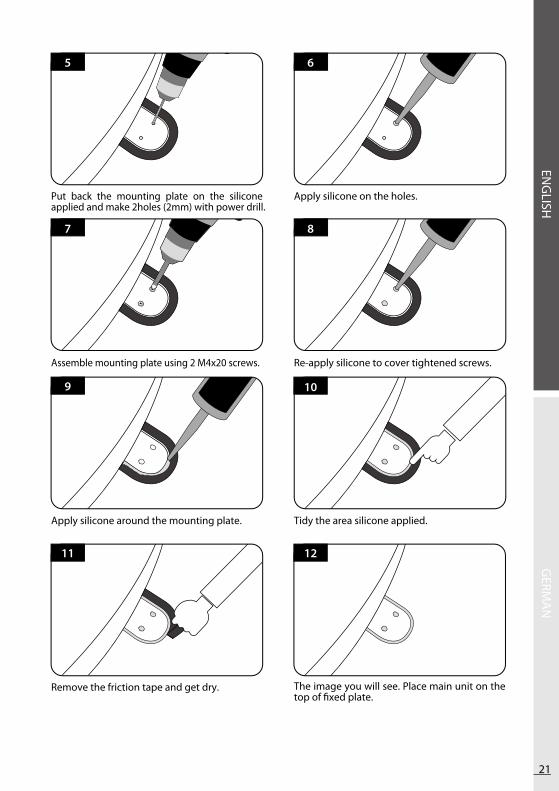
Assemble mounting plate using 2 M4x20 screws. Re-apply silicone to cover tightened screws.
8
6
Put back the mounting plate on the silicone applied and make 2holes (2mm) with power drill.
7
5
Apply silicone on the holes.
Remove the friction tape and get dry.
12
10
Apply silicone around the mounting plate.
11
9
Tidy the area silicone applied.
The image you will see. Place main unit on the top of fixed plate.

22
Put the cable inside the Cable holder as above picture.
Equipment to initiate Cable holder installation.
Fix cable holder on the car roof with 3 of M4x20 screws.
19
Place cable holder in the tape marked and make 3 of 2mm drill holes.
20
18
Apply silicone around the cable holder.
Insert Receiver & controller cable through the hole.
16
Arrange cable holder in front of (30cm apart from) antenna center by facing open side of cable holder toward projected part of the mounting plate. Then attach friction tape outside of cable holder.
17
15
Make 15mm drill hole in the center of the tape marking.
1413

ENG
LISHG
ERMA
N
23
Apply silicone around and on the top of screws.
21
Tidy silicon.
Connect black cable to the controller(middle) and grey cable to the receiver(Left).
Remove friction tape .
23 24
22
++ -
Use Power Input Cable and 5c Power Cable to Connect to Controller.
28
26
Power Input Cable.
27
Fix the Controller Bracket.Place the Controller at where you want.
25
Use Power Input Cable to Connect Car Battery (+/- Polarities have to be matched).

ENG
LISHG
ERMA
N
Inhalt
1. Allgemeine Informationen. . . . . . . . . . . . . . . . . . . . . . . . . . . . . . . . . . . . . . . . . . . . . . . . . . . . . . . . . . . . . . . . . . . . . . . . . . . .
. . . . . . . . . . . . . . . . . . . . . . . . . . . . . . . . . . . . . . . . . . . . . . . . . . . . . . . . . . .
. . . . . . . . . . . . . . . . . . . . . . . . . . . . . . . . . . . . . . . . . . . . . . . . . . . . . . . . . . . . . . . . . . . . . . . . . . . .
1-1.1-2.1-3.
223
ProduktvorstellungBestimmungsgemäße VerwendungSicherheitshinweise
2. Verpackungsinhalt. . . . . . . . . . . . . . . . . . . . . . . . . . . . . . . . . . . . . . . . . . . . . . . . . . . . . . . . . . . . . . . . . . . . . . . . . . . . . . . . . . . .
. . . . . . . . . . . . . . . . . . . . . . . . . . . . . . . . . . . . . . . . . . . . . . . . . . . . . . . . . . . . . . . . . . . . . . . . . . . .
2-1.2-2.
34
LieferumfangTeilebezeichnungen
3. Bedienungsanleitung. . . . . . . . . . . . . . . . . . . . . . . . . . . . . . . . . . . . . . . . . . . . . . . . . . . . . . . . . . . . . . . . . . . . . . . . . . . .
. . . . . . . . . . . . . . . . . . . . . . . . . . . . . . . . . . . . . . . . . . . . . . . . . . . . . . . . . . . . . . . . . . . . . . . .
. . . . . . . . . . . . . . . . . . . . . . . . . . . . . . . . . . . . . . . . . . . . . . . . . . . . . . . . . . . . . . . . . . . . . . . . . . . . . . . . . . .
3-1.3-2.3-3.
568
AnschlussdiagrammFunktionsbeschreibungKurzanleitung
4. Vorbereitung zum Ansehen von Satellitensendungen auf Smart Devices. . . . . . . . . . . . . . . . . . . . . . . . . . . . . . . . . . . . . . . . . . . . . . . . . . . . . . . . . . . . . . . . . . . . . . . . .
. . . . . . . . . . . . . . . . . . . . . . . . . . . . . . . . . . . . . . . . . . . . . . . . . . . . . . . . . . . . . . . . . . . . . . .
4-1.4-2.
911
NetzwerkeinstellungenSAT>IP-Client einrichten
5. Programm-Update. . . . . . . . . . . . . . . . . . . . . . . . . . . . . . . . . . . . . . . . . . . . . . . . . . . . . . . . . . .
. . . . . . . . . . . . . . . . . . . . . . . . . . . . . . . . . . . . . . . . . . . . . . . . . . . . . . . . . . . . . . . . . . . . . . . . . . . . . . . . .
5-1.5-2.
1213
Anschlussdiagramm für das UpdateUpdate-Vorgang
6. Fehlerbehebung. . . . . . . . . . . . . . . . . . . . . . . . . . . . . . . . . . . . . . . . . . . . . . . . . . . . . . . . . . . . . . . . . . . . . . . . . . . . . . .6-1. 17Fehlerbehebung
7. Technische Daten. . . . . . . . . . . . . . . . . . . . . . . . . . . . . . . . . . . . . . . . . . . . . . . . . . . . . . . . . . . . . . . . . . . . . . . . . . . . . . . . . .
. . . . . . . . . . . . . . . . . . . . . . . . . . . . . . . . . . . . . . . . . . . . . . . . . . . . . . . . . . . . . . . . . . . . . . . . . . . . . . .
7-1. 7-2.
1717
AbmessungenTechnische Daten
8. Einbau ins Wohnmobil. . . . . . . . . . . . . . . . . . . . . . . . . . . . . . . . . . . . . . . . . . . . . . . . . . . . . . . . . . . . . . . .
. . . . . . . . . . . . . . . . . . . . . . . . . . . . . . . . . . . . . . . . . . . . . . . . . . . . . . . . . . . . . . . . . . .
8-1. 8-2.
Platzbedarf für SNIPE DOME Air Ausrüstung für die Montage
1920
2
Jede Änderung des Geräts durch Hinzufügen oder Entfernen von Teilen ist nicht gestattet.
Die Verwendung von anderen Bauteilen, als ursprünglich eingebaut, ist nicht gestattet.
Die Installation am Fahrzeug darf nur von qualifiziertem Fachpersonal durchgeführt werden. Alle Anweisungen in
der Montageanleitung, die separat mitgeliefert werden, müssen sorgfältig befolgt werden.
Das Gerät bedarf keiner Wartung. Das Gehäuse des Geräts darf nicht geöffnet werden.
Überprüfung und Wartung sollte immer durch eine qualifiziertes Fachpersonal durchgeführt werden.
Alle relevanten und vorgeschriebenen Richtlinien der Automobilindustrie müssen beachtet werden.
Das Gerät darf nur auf Hartschalendächern installiert werden.
Vermeiden Sie Ihr Fahrzeug mit dem montierten Satellitensystem in Bürstenwaschanlagen, Waschstraßen
oder mit Hochdruckreinigern zu reinigen.
•
•
•
•
•
•
•
Bitte beachten Sie auch die folgenden Hinweise des Herstellers:
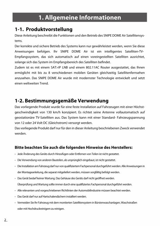
1-1. ProduktvorstellungDiese Anleitung beschreibt die Funktionen und den Betrieb des SNIPE DOME Air Satellitensys-
tems.
Der korrekte und sichere Betrieb des Systems kann nur gewährleistet werden, wenn Sie diese
Anweisungen befolgen. Ihr SNIPE DOME Air ist ein intelligentes Satelliten-TV-
Empfangssystem, das sich automatisch auf einen voreingestellten Satelliten ausrichtet,
solange sich das System im Empfangsbereich des Satelliten befindet.
Zudem ist es mit einem SAT>IP LNB und einem 802.11AC Router ausgestattet, das Ihnen
ermöglicht mit bis zu 8 verschiedenen mobilen Geräten gleichzeitig Satellitenfernsehen
anzusehen. Das SNIPE DOME Air wurde mit modernster Technologie entwickelt und setzt
einen weltweiten Trend.
1-2. Bestimmungsgemäße VerwendungDas vorliegende Produkt wurde für eine feste Installation auf Fahrzeugen mit einer Höchst-
geschwindigkeit von 130 km/h konzipiert. Es richtet seine Antenne vollautomatisch auf
geostationäre TV-Satelliten aus. Das System kann mit einer Standard- Fahrzeugspannung
von 12 oder 24 Volt DC (Gleichstrom) versorgt werden.
Das vorliegende Produkt darf nur für den in dieser Anleitung beschriebenen Zweck verwendet
werden.
1. Allgemeine Informationen

3
ENG
LISHG
ERMA
N
2-1. Lieferumfang
1-3. Sicherheitshinweise
Um zu gewährleisten, dass Ihr SNIPE DOME AIR ordnungsgemäß
funktioniert, müssen Sie sicherstellen, dass Sie die Bedienungsanleitung in
diesem Handbuch befolgen und es wie vorgesehen verwenden. Wenn das
System aufgrund der Fahrlässigkeit des Benutzers nicht vollständig entfernt
werden kann, dann liegt es in Ihrer Verantwortung zu überprüfen, ob die
Antenne ordnungsgemäß verstaut ist. Bitte beachten Sie auch, dass unterschiedliche
rechtliche Anforderungen für den Betrieb von elektrischen und elektronischen
Geräten in verschiedenen Ländern gelten. Als Benutzer dieses Geräts, sind Sie
für die Einhaltung der relevanten Gesetze und Bestimmungen verantwortlich.
Der Hersteller haftet nicht für direkten oder indirekten Schaden an dem
System, an Kraftfahrzeugen oder anderen Geräten auf Grund von ungeeigne-
ter Verwendung von Batterien oder fehlerhafter Montage oder falscher
Kabelverbindungen.
Haupteinheit Steuergerät Steuergeräthalterung
Kabelverschraubung
Stromversorgungskabel
KabelhalterEmpfangerkabel(12m – Graue Farbe)
5C Stromkabel (7m)
BedienungsanleitungSchraube M4x20(11),M4x16(2)
2. Verpackungsinhalt

4
2-2. Teilebezeichnung
Haupteinheit
Antenne
Befestigungsplatte
zum Satellitenempfänger(Option)
zum Steuergerät
zum Satellitenempfänger
Steuergerät
WLAN Statusanzeige
GPS-Statusanzeige
Satelliten-Statusanzeige
WLAN -Taste
OK -Taste
Satelliten CCW/CW-TastenNetzschalt
Halterung
Zur Haupteinheit
Stromanschluss : DC 12~24V
USB-Anschluss :
Für das Aktualisieren der Satelliten-Informationen

5
ENG
LISHG
ERMA
N
3-1. Anschlussdiagramm
Verwenden Sie das Controllerkabel für die Verbindung zwischen Controller und
Antenne. Das Controllerkabel sieht ähnlich aus wie das Antennenempfangskabel,
aber Sie können sie über die Farbe und Beschriftung unterscheiden.
Haupteinheit
Um eine Sendung anzusehen, muss das Smart Device mit einem geeigneten Programm oder einer geeigneten App ausgestattet sein. (Siehe http://satip.info)
HINWEIS
Empf
änge
rkab
el
Empfänger
Fernseher
5C S
trom
kabe
l (7m
) Steuergerät
Stro
mve
rsor
gung
skab
el
3. Bedienungsanleitung

6
3-2. Funktionsbeschreibung
Beim Einschalten des Geräts leuchten alle LEDs zwei
Mal auf.
Wenn der gewahlte Satellit gefunden wurde, leuchtet die
Satellitenanzeige dauerhaft auf
Funktion Beschreibung
Satellitenanzeigeleuchtet auf
Bedienung
i.
ii.
i.
ii.
iii.
Funktion Beschreibung Bedienung
B. Auswahl des Satelliten
Schaltfläche "OK"
leuchtet dauerhaft
"Satellit CCW/CW-Taste"leuchtet
C. Searching the satellite
A. Einschalten
Wenn alle Kabel angeschlossen sind, schalten Sie die
"Power"-Taste auf der Oberseite des Controllers ein.
Wenn die WLAN-LED aufhört zu blinken und dauerhaft leuchtet,
ist das Gerät betriebsbereit. Weiter mit den nächsten Schritten.
Funktion Beschreibung
"Power"-Taste
Bedienung
Sobald die Antenne und der Controller verbunden sind, können
Sie den gewünschten Satelliten auswählen und ändern.
Wählen Sie den bevorzugen Satelliten mit Hilfe der "CCW/CW"-
Tasten und drücken Sie anschließend auf die Schaltfläche "OK",
um die Einstellung festzulegen.
Wenn Sie den falschen Satelliten ausgewählt haben, können
Sie den Zielsatelliten mit Hilfe der "CCW/CW"-Tasten erneut
suchen und anschließend durch einen Tastendruck auf die
Schaltfläche "OK" die neue Einstellung übernehmen.
i.
Nach dem Einschalten werden alle LED zweimal.Alle LEDs blinkt
"WLAN"-Statusanzeige blink
ii.
iii.

ENG
LISHG
ERMA
N
7
Wenn Sie sich keine SAT>IP Kanäle ansehen, drücken Sie die WLAN-Taste, um den Router auszuschalten und den Stromverbrauch zu minimieren.
Hinweis
Drücken Sie einfach die Taste zum Ein-/Ausschalten des Routers.
Halten Sie die Taste für mehr als 5 Sekunden gedrückt, um den
Router zurückzusetzen.
i.
ii.
Funktion Beschreibung Bedienung
E. WLAN-Router EIN/AUS
Wenn Sie den falschen Satelliten ausgewählt haben,
können Sie erneut mit den CCW/CW-Tasten den gewun-
schten Satelliten auswahlen und mit der OK-Taste die
Auswahl bestatigen.
i.
Funktion Beschreibung Bedienung
OK-Taste
D. Changing the satellite
Die GPS-LED bestätigt die Bestimmung der aktuel-
len Position über 24 GPS-Satelliten.
Wenn SNIPE DOME Air die GPS-Signale identifiziert,
leuchtet die GPS-LED unabhängig vom Betrieb-
szustand der Antenne auf.
GPS trägt zur Beschleunigung des Suchvorgangs und
zum Auffangen des besten Satellitensignals bei, sodass
SNIPE DOME Air den benötigten Erhebungs- und
Azimutwinkel besser berechnen kann.
Funktion Beschreibung
“GPS”-Statusanzeige blinkt
Bedienung
i.
Während des Programm-Update-Vorgangs blinkt die
GPS-LED-Anzeige, was allerdings nicht auf den Empfang
der GPS-Signale hinweist.
iii.
ii.
F. GPS LED light
"WLAN"-Taste
Mit den CCW / CW Tasten den gewünschten Satelliten
auswahlent

8
3-3. Kurzanleitung
Bedienung(Suche nach Satelliten)
Einschalten mit der "Power "-Taste auf der Oberseite des Controllers.
Beim Starten leuchten alle LEDs zweimal auf.
Warten Sie, bis die "WLAN-Status-LED" & eine "Satelliten"-LED, entweder die,
des zuvor ausgewählten oder des ersten Satelliten im Controller, dauerhaft
aufleuchtet.
Wählen Sie den gewünschten Satelliten mit Hilfe der "CW/CCW"-Tasten und
drücken Sie dann die Taste "OK" um zu bestätigen.
Die Satelliten-LED wird zu blinken anfangen. Warten Sie, bis sie dauerhaft
leuchtet.
Wenn die Satelliten-LED dauerhaft leuchtet, wurde der gewählte Satellit
gefunden und ein Signal kann auf dem Satelliten-TV gesehen werden.
Wenn Sie sich nicht gerade SAT>IP Kanäle ansehen, drücken Sie die WLAN-
Taste und um die Stromversorgung auszuschalten.
1.
2.
3.
4.
5.
6.
7.
Klassifikation Beschreibung

ENG
LISHG
ERMA
N
9
a. WLAN-Netzwerk Einstellungen für die Anzeige von SAT>IP-Übertragungen auf Mobiltelefonen
Einstellungen WLAN Wählen Sie das WLAN-Netzwerk "SATIPLINK2G" oder "SATIPLINK5G"
►Wenn das Mobiltelefon oder das Tablett Dual-Band-WLAN besitzt, können beide Netzwerke SATIPLINK2G, SATIPLINK5G verwendet werden. Ansonsten wird nur SATIPLINK2G gefunden.
1)
Android OS
Einstellungen WLAN Wählen Sie das WLAN-Netzwerk "SATIPLINK2G" oder "SATIPLINK5G"1)
iOS
Windows 8 / 7 / Vista
Gehen Sie zu "Einstellungen" (Win 8) / "Start" (Win7/Vista) � "Systemsteuerung".
Klicken Sie mit der linken Maustaste auf "Netzwerk und Internet" "Netzwerk- und Freigabecenter" "Netzwerkverbindungen herstellen" Auswahl von "SATIPLINK2G
1)
2)
Windows XP/2000
Gehen Sie auf "Start" "Systemsteuerung".
Klicken Sie mit der linken Maustaste auf "Netzwerk- und Internetverbindungen"" Netzwerkverbindungen" Auswahl von "SATIPLINK2G"
1)
2)
MAC OS
Klicken Sie auf das "Apple"-Menü "Systemeinstellungen".2)Klicken Sie auf das Symbol "Netzwerk" Auswahl von "SATIPLINK2G"
1)
2)
Der PC muss WLAN-Netzwerke unterstützen.
Wenn der PC Dual-Band-WLAN unterstützt, können SATIPLINK2G und SATIPLINK5G
verwendet werden, aber normalerweise wird nur SATIPLINK 2G gefunden.
Es wird empfohlen SATIPLINK5G zu verwenden für stabileren Empfang der Satellitenkanäle.
Es ist normal, dass sich eine zusätzliche Nummer am Ende des SSID befindet (ex.
SATIPLINK2GXX,SATIPLINK5GXX, etc.).
▶▶
▶▶
b. WLAN-Netzwerk Einstellungen die Anzeige von SAT>IP-Übertragungen auf Laptops
4-1 Netzwerkeinstellungen
A. Einrichten des WLAN-Netzwerks
4. Vorbereitung zum Ansehen von Satellitensendungen auf Smart Devices

10
Die http://satiplink.com Seite steht erst nach Zugang des SATIPLINK2G (oder 5G) WLAN-Netzwerks über den DOME AIR Router zu Verfügung.
HINWEIS
Nur Großbuchstaben, wenn Sie schreiben Passwort.
HINWEIS
Nach Auswahl des SATIPLINK2G (oder SATIPLINK 5G) WLAN-NetzwerksÖffnen Sie Ihren Browser und geben Sie http://satiplink.com in das Adressfeld ein, um die Web Management Seite des Routers zu besuchen.
a.b.
Default address : http://satiplink.com2.4G SSID : SATIPLINK 2G 5G SSID : SATIPLINK 5G Default PASSWORD : SATIPLINK25
Gehen Sie zu "Einstellungen" (Win 8) / "Start" (Win7/Vista) > "Systemsteuerung".
Klicken Sie mit der linken Maustaste auf "Netzwerk und Internet" > "Netzwerk- und Freigabecenter" >
"Adaptereinstellungen ändern" (Win8/7) / "Netzwerkverbindungen verwalten" (Win Vista).
Klicken Sie mit der rechten Maustaste auf "LAN-Verbindung" und klicken Sie mit der linken Maustaste auf
"Eigenschaften".
Doppelklicken Sie auf "Internet Protocol Version 4 (TCP/IPv4)".
Wählen Sie "IP-Adresse automatisch beziehen" und "DNS-Serveradresse automatisch beziehen" aus und
klicken Sie mit der linken Maustaste auf "OK".
1)
2)
3)
4)
5)
Wireless Setup, konfigurieren Sie den
Netzwerknamens (SSID) und das Kennwort.
Klicken Sie mit der linken Maustaste auf
"Speichern", um die Einstellungen anzuwenden.
Sie können auf die Taste [Erweiterte
Einstellungen] klicken, für zusätzliche
Internetverbindungen und weitere
Einstellungen.
1)
2)
3)
Change the router password
Manage the router setting
If the internet connection is bad, try changing
the wireless channel
-
-
-
unten stehenden Punkte
Klicken Sie auf das "Apple Menü" > "Systemeinstellungen".
Klicken Sie auf das Symbol "Netzwerk".
Klicken Sie auf "Ethernet" im linken Feld und klicken Sie auf "Erweitert" in der rechten unteren Ecke.
In den oberen Optionen wählen Sie "TCP/IP".
Im Pull-down-Menü neben "IPv4 konfigurieren", wählen Sie die Option "DHCP verwenden".
Klicken Sie auf "OK", dann auf "Anwenden".
1)
2)
3)
4)
5)
6)
Für MAC OS
Falls SATIPLINK2G nicht gefunden werden kann, überprüfen Sie bitte die
B. Konfigurieren Sie den Router über die Web Management Seite

ENG
LISHG
ERMA
N
11
4-2 SAT>IP-Client einrichtenDie SAT>IP-Client ist entweder ein Softwareprogramm oder ein STB-Gerät, das für den Empfang
des SAT>IP Streams verwendet wird.
Die SAT>IP App für Tablets oder Smartphones können Sie im Apple App Store oder auf Google
Play finden.
Fernseher kommen entweder mit einer integrierten SAT>IP Client Software oder sie benötigen
einen separaten Hardware-Klienten (STB, Set Top Box), der an das Fernsehgerät angeschlossen
wird.
Bitte lesen Sie die beigefügte Kurzanleitung für detaillierte Informationen.Für die neuesten Informationen über SAT>IP-Anwendungen und PC Programme, gehen Sie auf: www.satip.info.
--
HINWEIS
a. Wie wird die App für iOS/Android Smartphones und Tablets heruntergeladen/verwendet? Herunterladen der SAT>IP App wie "Elgato SAT>IP" aus dem Apple App Store oder von Google Play.
1.
b. Verwendung des PC-ViewersMit dem Microsoft Windows®-Betriebssystem:Von dem Programm "DVBViewer" können Sie eine kostenlose Version auf www.satip.info finden.Im Menü Optionen, können Sie Ihren SAT>IP- Server auswählen und die Einstellungen ändern.
1.2.3.
Installieren Sie die App auf Ihrem iOS- oder Android-Gerät.Starten Sie die App.
2.3.
SAT>IP App ermöglicht es unverschlüsselte Programme zu empfangen.-

12
Haupteinheit
Bitte lesen Sie diese Update-Anleitung gründlich durch, bevor Sie mit dem Update fortfahren.
HINWEIS
5-1. Anschlussdiagramm für das Update
"Der USB-Anschluss wird nur für das Aktualisieren der Satelliten-Informationen verwendet"
Schließen Sie einfach den Controller an den PC mittels eines USB-Kabels an. Das USB-Kabel ist nicht im Lieferumfang enthalten.
Das Suchprogramm mit den Zielsatelliten ist vorprogrammiert. Wenn es keine
Probleme bei der Suche der Satelliten gibt, benötigen Sie den Update-Prozess nicht.
※
USB
-Kab
el
B Typ
A Typ
5C S
teue
rger
ätka
bel Steuergerät
PCStromversorgungskabel
5. Programm-Update

ENG
LISHG
ERMA
N
13
5-2. Update-VorgangMit SNIPE DOME Air Programm werden die Satellitendaten Ihres SNIPE DOME Air aktualisiert.
Bitte verbinden Sie die Haupteinheit - Controller - PC.ii. Laden Sie das Update-Programm von unserer Website (http://www.selfsat.com) wie folgt herunter.
i.ii.
Klicken Sie bei [S/W Update] auf das Modell, das Sie aktualisieren möchten und laden Sie das
Update-Programm herunter.
Laden Sie die Satellitendaten herunter.
(Überprüfen Sie das Gerätemodell und die Region, um die richtigen Satellitendaten herunterzuladen)
Laden Sie die USB Serial Driver Datei herunter.
01.
02.
03.
Installieren Sie das [USB-Laufwerk]iii.Verbinden Sie das USB-Kabel und schalten Sie
den Controller ein. Bitte überprüfen Sie ob der
[USB Serial Converter] Port am [PC und Gerät]
aktiviert wurde.
Wenn alles korrekt angeschlossen ist und der
Controller eingeschaltet ist, aber der [USB Serial
Converter] noch nicht aktiv ist, laden Sie bitte die
USB-Treiber von der Homepage herunter.
01.
02.
Installationiv.
Bitte laden Sie das SNIPE Dome Air Update
Programm herunter.
01.
Entpacken des[Update-Programms].
Öffnen Sie [Setup.exe] und folgenden Sie den
Bildern.
-
-
5
4
1
2
5

14
Wenn Sie die Meldung [ungültiger Port] nach dem Klicken auf [Scan Ports] sehen, überprüfen Sie bitte, ob Sie den richtigen Port ausgewählt haben und wenn Sie die Meldung [ungültiger Port] auch beim richtigen Port sehen, ändern Sie bitte die Einstellungen wie unten; Wenn Sie diese Meldung nicht sehen, müssen Sie den Anweisungen bis 5-3 nicht folgen.
HINWEIS
Update durchführenv.Öffnen Sie das installierte Update-Programm und
Sie sehen das Programmfenster.
01.
Schalten Sie den Controller ein und klicken Sie
auf [Ports scannen]. Der Port-Name kann sich je
nach PC-Modell unterscheiden.
02.
Klicken Sie auf den COM-Anschluss im [Geräte Manager] und anschließend auf Eigenschaften.
02-a. Gehen Sie zu [Port Einstellungen]02-b.
Gehen Sie zu [Erweitert…]02-c. Ändern Sie die COM-Portnummer auf eine niedrigere Nummer und bestätigen Sie mit [OK].
02-d.
a
b
c
d

ENG
LISHG
ERMA
N
15
Mindestens 1 TP sollte zum Aktualisieren ausgewählt sein. Die Satelliten sollten einer nach dem anderen aktualisiert werden.
HINWEIS
Öffnen Sie die Datei (*.idt) wie auf den Bildern.03.
Klicken Sie auf Schaltfläche [Connect] und prüfen
Sie ob die [Update]-Taste aktiviert wurde, wie im
folgenden Bild.
04.
Prüfen Sie Satellit und TP zum Aktualisieren und
klicken Sie auf [Update].
05.
Die GPS-LED blinkt während dem Update. (Wenn Sie das Update nicht korrekt abläuft, blinkt die LED-Anzeige nicht. In diesem Fall, prüfen Sie bitte, ob alle Kabel der Hauptein-heit - Controller - PC korrekt angeschlossen sind und die Controller-LED aktiviert ist)
HINWEIS
Der Update-Prozess erfolgt wie auf dem Bild.06.

16
Schalten Sie das Gerät nicht aus oder trennen Sie das Kabel vor dem Abschluss des Update-Prozesses.Wie die Satellitendaten genau aktualisiert werden, kann sich ändern, um die neuesten Satellitendaten zu reflektieren.Bitte stellen Sie sicher, dass Sie Updateanleitung über unsere Website (www.selfsat.com) beziehen.
HINWEIS
Sie können das Update auch manuell fortsetzten, indem Sie die Werte auf dem Bildschirm entsprechend ändern.Wenn Sie falsche Daten eingeben, wird eine Fehlermeldung angezeigt.-
-
Lesen Sie bitte die Fehlermeldung und korrigieren Sie die Angaben entsprechend der Anweisung.Wenn Sie die richtigen Daten eingegeben haben und der [Data Format Fehler] weiterhin angezeigt wird, nehmen Sie bitte andere Daten oder kontaktieren Sie [email protected].
HINWEIS
Im Falle, dass die Stromversorgung des Controllers ausgeschaltet oder das Kabel getrennt wurde oder irgendetwas passiert ist, dass den Update-Prozess gestoppt hat, fangen Sie bitte mit dem Update-Prozess von vorne an.
HINWEIS
Zuletzt sollten das SNIPE DOME Air testen und überprüfen, ob es die aktualisierten Satelliten richtig findet. Wenn das SNIPE DOME Air, selbst nach der abgeschlossenen Aktualisierung, die Satelliten nicht finden kann, starten Sie das Update erneut oder wenden Sie sich an [email protected].
vi.
Überprüfen [Update wurde abgeschlossen].07.
Falls Sie weitere Satelliten aktualisieren möchten, wählen Sie bitte die gewünschten Satelliten und
verfahren mit ihnen ebenso.
08.

ENG
LISHG
ERMA
N
17
Es gibt eine Reihe von Ursachen, die die Signalqualität oder den Betrieb des SNIPE
DOME Air beeinträchtigen können. Der folgende Abschnitt befasst sich mit den
Ursachen und deren möglichen Lösungen.
i.
Die Verbindung zwischen Strom und Steuergerat.Die Verbindung zwischen dem Steuergerat und der Antenne. Stellen Sie sicher, dass der rechte. Anschluss der Antenne an das Steuergerat angeschlossen ist.
Überprüfen Sie, ob das Stromversorgungskabel beschädigt wurde.ii.
A. Keine Reaktion, wenn das Steuergerät eingeschaltet wirdSämtliche Anschlüsse erneut überprüfen.
C. Mechanische Probleme
i.
Schalten Sie den Netzschalter aus und wieder ein.
Die Antenne bewegt sich nicht in die gewünschte Position.
ii. Schalten Sie den Netzschalter aus und wieder ein. Bei weiter bestehenden Problemen wenden. Sie sich an Ihren Vertragshandler.
Die Antenne macht Geräusche, aber bewegt sich nicht
i.
ii.
B. Fehler bei der Suche des ausgewählten SatellitenHindernisse, wie Gebäude oder Bäume, können Satellitensignale blockieren oder die Qualität des Signalempfangs beeinträchtigen. Vergewissern Sie sich, dass die Umgebung Richtung Süden frei von Hindernissen ist.
Aktualisieren Sie das Programm des Steuergeräts oft, sodass die Satellitendaten des SNIPE DOME Air stets aktuell bleiben.
i.
D. Weitere UrsachenWenn die Kabel des Systems nicht ordnungsgemäß angeschlossen sind, läuft das system nicht einwandfrei. Im Falle eines Kabelschadens, wenden Sie sich bitte an Ihren vertragshändler.
i.
ii.
iii.
E. Was kann ich tun, wenn ich auf mein "Wireless TV" nicht zugreifen kann?Stellen Sie sicher, dass das DOME Air den Satelliten korrekt erfasst hat.
Überprüfen Sie den Gerätestatus (Korrekter Satellitensuchlauf, usw.)
Drücken Sie die WLAN-Taste für mehr als 5 Sekunden, um den Router zurückzusetzen und überprüfen Sie die Kanäle erneut.
6. Fehlerbehebung

18
7-1. Abmessungen
Abmessungen
Gewicht (Haupteinheit )
Antennengewinn
Min EIRP
Polarisation
LNB-Ausgang
LNB-Eingangsfrequenz
LNB-Ausgangsfrequenz
Winkelbereich
Stromverbrauch
Spannungsversorgung
Stromverbrauch
Betriebstemperatur
660 x 315 mm
9.0 kg
33.7 dBi @ 12.7GHz
50dBW
Linear (Horizontal / vertikal)
1 Ausgang (optional 2 Ausgange)
10.7 ~ 12.75 GHz
950 ~ 2,150MHz
(EL)15°~75°/(AZ) 390°
180 Sekunden (Durchschnitt)
70W (wahrend des Suchlaufs))
DC 12~24V
-30°C ~ +60°C
7-2. Technische Datena. Antenne
CPU
Flash / Ram
Wireless LAN-Schnittstelle
Frequenzband
Antenne
7Realtek RTL8197D eingebettet 660 MHz
8MB / 64MB DDR2
IEEE802.11ac (2Tx 2Rx / 867 Mbps)
IEEE802.11a,b,g/n (2Tx 2Rx / 300 Mbps)
5 GHz/2.4 GHz (20 / 40 / 80 MHz Bandbreite Kanalbündelung
2.4GHz : 5dBi Dipole 2ea MIMO Technology
5GHz : 5dBi Dipole 2ea MIMO Technology
b. Router
66.0cm 66.0cm
31.5cm
7. Technische Daten

ENG
LISHG
ERMA
N
19
Achten Sie darauf , dass das SNIPE DOME Air genügend Platz zum Zusammenklappen sowie
für den Betrieb hat.
8-1 . Platzbedarf für das SNIPE DOME Air
Fahrtrichtung
Fa
hrt
ric
htu
ng
Fahrzeugheck
31.5cm
66.0
cm
8. Einbau ins Wohnmobil
66.0cm

20
5C Stromkabel (7m)
Empfangerkabel(12m – Graue Farbe)
Stromversorgungskabel
Silikon
Schraube M4x20(11), M4x16(2)
Kabelhalter
Kabelverschraubung
Isolierband
2mm Bohrer, 15mm Bohrer
Akkubohrmaschine
Putzlappen
1
2
3
4
5
6
7
8
9
10
11
7-2. Ausrüstung für die Montage
Legen Sie die Befestigungsplatte zur Seite undverteilen Sie das Silikon innerhalb der umran-deten Fläche.
Kleben Sie das Isolierband mit einem Abstandvon 4mm um die Befestigungsplatte auf dem Dach.
4
2
FRONT
Reinigen Sie die Oberfläche mit dem Putzlap-pen.
3
1
Lokalisieren SNIPE DOME Air in der Mitte aufdem Dach.
4
5 6
7
8
10
1
2 3
9
SNIPE DOME Air -Installation auf dem Dach
(gleiche für alle 4 Montage-Plattenkanten)
11

ENG
LISHG
ERMA
N
21
Verschrauben Sie die Platte mit 2 Schrauben. Bedecken Sie die Schrauben mit Silikon.
8
6
Platzieren Sie die Befestigungsplatte auf dem Silikon und bohren Sie 2 Löcher (2mm).
7
5
Verteilen Sie das Silikon auf die Löchern.
Entfernen Sie das Isolierband und lassen Sie das Silikon trocknen.
12
10
Verteilen Sie das Silikon um die Befestigungsplatte herum.
11
9
Glätten Sie das Silikon.
Das Ergebnis sollte diesem Bild entsprechen.Platzieren Sie die Haupteinheit auf derBefestigungsplatte.

22
Verlegen Sie die Kabel wie auf dem Bild zu sehen.
Ausrüstung zur Montage des Kabelhalters.
Befestigen Sie den Kabelhalter auf dem Dach mit 3 M4x20 Schrauben.
19
Platzieren Sie den Kabelhalter auf der mit Isolierband markierten Fläche und bohren Sie 3 2mm Löcher.
20
18
Verteilen Sie das Silikon um den Kabelhalter herum.
Ziehen Sie das Empfangerkabel und das Steuergerätkabel durch das Loch.
16
Positionieren Sie den Kabelhalter mittig vor derAntenne (30cm entfernt). Die offene Seite desKabelhalters soll Richtung Befestigungsplatte zeigen. Danach kleben Sie das Isolierband um den Kabelhalter herum.
17
15
Bohren Sie ein 15mm Loch in die Mitte der mitIsolierband markierten Fläche.
1413

ENG
LISHG
ERMA
N
23
Verteilen Sie das Silikon auf den Schrauben.
21
Glätten Sie das Silikon.
Verbinden Sie das schwarze Kabel mit dem teuergerät (Mitte) und das graue Kabel mit dem Empfänger (links)
Entfernen Sie das Isolierband.
23 24
22
++ -
Verbinden Sie das Stromversorgungskabel unddas 5C Stromkabel mit dem Steuergerät.
28
26
Stromversorgungskabel
27
Bringen Sie die Steuergeräthalterung an.Platzieren Sie das Steuergerät am gewünschtenOrt.
25
Verbinden Sie das Stromversorgungskabel mit derBatterie (+/- Polaritäten müssen pass.en)