Embed Size (px)
Citation preview
SARA Application Server 3.1.5 User’s Guide

Please Read
Important Please read this entire guide. If this guide provides installation or operation instructions, give particular attention to all safety statements included in this guide.

Notices
Trademark Acknowledgments
Cisco and the Cisco logo are trademarks or registered trademarks of Cisco and/or its affiliates in the U.S. and other countries. A listing of Cisco's trademarks can be found at www.cisco.com/go/trademarks
Third party trademarks mentioned are the property of their respective owners.
.
The use of the word partner does not imply a partnership relationship between Cisco and any other company. (1009R)
Publication Disclaimer Cisco Systems, Inc. assumes no responsibility for errors or omissions that may appear in this publication. We reserve the right to change this publication at any time without notice. This document is not to be construed as conferring by implication, estoppel, or otherwise any license or right under any copyright or patent, whether or not the use of any information in this document employs an invention claimed in any existing or later issued patent.
Copyright
Information in this publication is subject to change without notice. No part of this publication may be reproduced or transmitted in any form, by photocopy, microfilm, xerography, or any other means, or incorporated into any information retrieval system, electronic or mechanical, for any purpose, without the express permission of Cisco Systems, Inc.
© 2005, 2012 Cisco and/or its affiliates. All rights reserved. Printed in the United States of America.
Contents
4009747 Rev B iii
About This Guide ........................................................................................................................................ v About This Guide
Chapter 1 Introducing the SARA Server Overview ........................................................................................................................ 1-1 Understand the DBDS Network ................................................................................. 1-2 View DNCS Monitor Windows .................................................................................. 1-4 Online Help .................................................................................................................... 1-9
Chapter 2 Getting Started Overview ........................................................................................................................ 2-1 Power On the SARA Server Workstation .................................................................. 2-2 Start SARA Server Processes ....................................................................................... 2-3
Chapter 3 Setting Up Language Support Overview ........................................................................................................................ 3-1 Set Up Supported Languages ...................................................................................... 3-2
Chapter 4 Defining PPV Services and Events Overview ........................................................................................................................ 4-1 Define PPV Services ...................................................................................................... 4-2 Understand Windows and Barkers .......................................................................... 4-10 Define PPV Events ...................................................................................................... 4-16
Chapter 5 Setting Up the Interactive Program Guide Overview ........................................................................................................................ 5-1 Before You Begin ........................................................................................................... 5-2 Set Up the IPG ............................................................................................................... 5-5 Edit IPG Data ............................................................................................................... 5-15
Chapter 6 Setting Up a Virtual Channel Service Overview ........................................................................................................................ 6-1 Configure the VCS Broadcast File System (BFS) ...................................................... 6-2 Build a Virtual Channel Source File ........................................................................... 6-6 Set Up a Virtual Channel Service ................................................................................ 6-9
Continued on next page
Contents, Continued
iv 4009747 Rev B
Chapter 7 Enabling Tracing on the SARA Server Overview ........................................................................................................................ 7-1 Enable Tracing ............................................................................................................... 7-2 View the Log Files ......................................................................................................... 7-6
Chapter 8 Adding a dvd Server to the BFS and Updating the dvd Server With New Files Overview ........................................................................................................................ 8-1 Add a DVD Server to the BFS ..................................................................................... 8-2 Update a DVD Server With New Files ...................................................................... 8-4
Chapter 9 Customer Information .................................................................................................... 9-2
Glossary
Index

4009747 Rev B v
About This Guide
Introduction The Cisco Resident Application (SARA) Server works with the Digital Network Control System (DNCS) to deliver digital applications to subscribers. The SARA Server and the DNCS form the core of the Digital Broadband Delivery System (DBDS). The DBDS delivers broadcast data and digital applications from the headend to the subscribers’ homes.
This guide provides procedures for setting up and managing digital applications such as pay-per-view (PPV) and the Interactive Program Guide (IPG) on the SARA Server.
Important: This guide contains procedures for defining digital applications as well as deleting and changing the definitions for these applications. You will not complete these procedures in the order they are presented here. In addition, you will not necessarily use all of the procedures in this guide, depending on the applications that you offer to your subscribers.
Note: The illustrations and screen captures shown in this guide may not exactly match what displays on your system.
Purpose The purpose of this guide is to enable users to manage the applications that reside on SARA Server 3.1.5. You will learn how to set up, or provision, each of the applications that reside on the SARA Server.
Prerequisite SARA Server software version 3.1.5 requires one of the following system releases:
• System Release 2.5 and later
• SR 3.5 and later
• SR CV3.4 and later
• SR 4.0 and later
Audience This guide is intended for system operators who are using SARA Server 3.1.5 with one of the system releases listed earlier.
Scope This guide provides procedures for system operators who are using SARA Server software version 3.1.5 only.
Document Version This is the first release of this guide.

4009747 Rev B Introducing the SARA Server 1-1
Chapter 1 Introducing the SARA Server
Overview
Introduction
This chapter explains the purpose of the SARA Server, how the SARA Server differs from the Digital Network Control System (DNCS), and how the SARA Server fits into the Digital Broadband Delivery System (DBDS). In addition, this chapter provides an overview of how to monitor the status of the SARA Server and how to use the online Help system.
In This Chapter This chapter contains the following topics.
Topic See Page
Understand the DBDS Network 1-2
View DNCS Monitor Windows 1-4
Online Help 1-9

1-2 Introducing the SARA Server 4009747 Rev B
Understand the DBDS Network
Introduction
The SARA Server is a workstation that transfers data to the DNCS. The SARA Server runs the applications that are necessary for providing digital services to subscribers. You must set up, or provision, the following applications so that the DBDS can deliver digital services to subscribers: • Virtual Channel Service (VCS) • Interactive Program Guide (IPG) • Foreign language support • DHCT Configuration • Pay-Per-View (PPV) • Digital Video Disc (DVD)
Important Note for Multiple-Site (RCS-Enabled) Systems: When provisioning an application for the Broadcast File System (BFS), manually set up any BFS server or source for the “AllSites” site only, and not for any other individual sites in your system. Otherwise, the server and source will fail. Currently, VCS and DVD are the only applications the SARA Server uses that must be set up in this manner. Chapter 6 and Chapter 8 provide more information on setting up applications for RCS-enabled systems.
The DNCS graphical user interface (GUI) allows you to manage and monitor the SARA Server. The following two windows are available on the DNCS desktop and provide the means of entry to the SARA Server as needed: • DNCS Administrative Console Status • DNCS Administrative Console
The View DNCS Monitor Windows section, later in this chapter, describes these windows and explains how they relate to the SARA Server.
4009747 Rev B Introducing the SARA Server 1-3
Understand the DBDS Network, Continued
The DBDS
This section briefly describes the relationship between the SARA Server and the DBDS and explains how the SARA Server works with the DBDS.
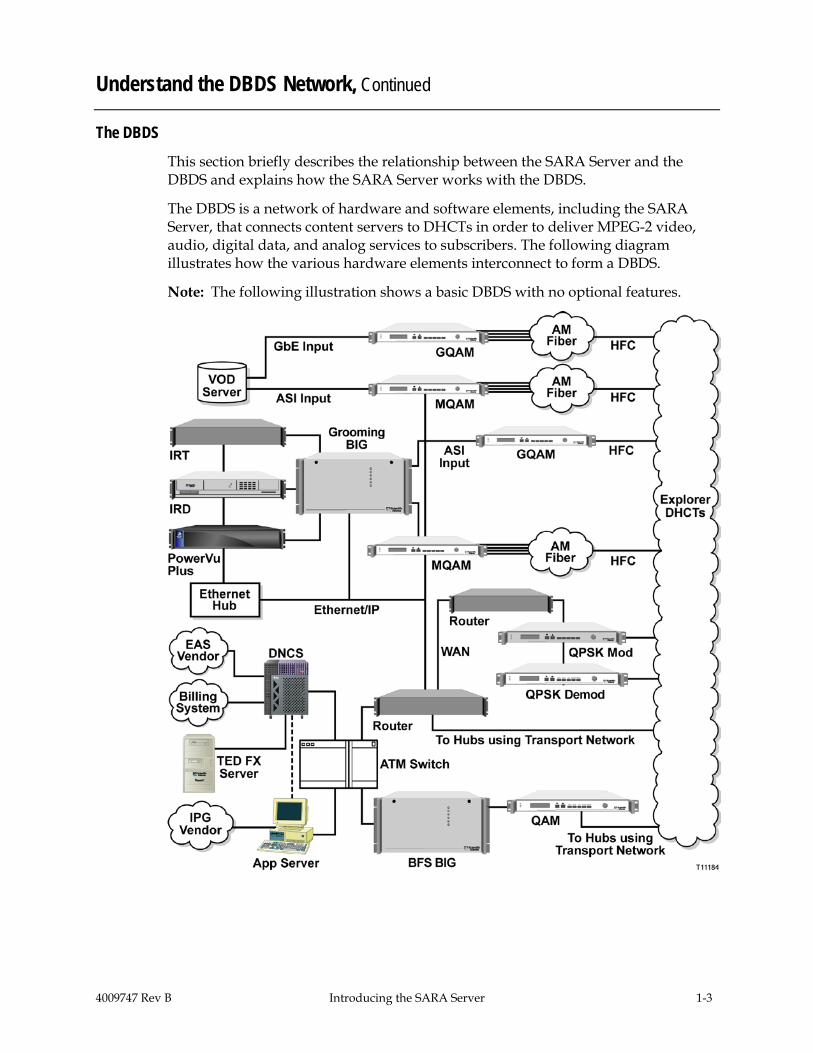
The DBDS is a network of hardware and software elements, including the SARA Server, that connects content servers to DHCTs in order to deliver MPEG-2 video, audio, digital data, and analog services to subscribers. The following diagram illustrates how the various hardware elements interconnect to form a DBDS.
Note: The following illustration shows a basic DBDS with no optional features.

1-4 Introducing the SARA Server 4009747 Rev B
View DNCS Monitor Windows
DNCS Administrative Console Status Window
Use the DNCS Administrative Console Status window to determine the overall status of various processes and network elements. To determine the status of the individual SARA Server processes, see AppServer Control Window, next in this section.
The DNCS Administrative Console Status window is divided into the following four areas: • DNCS • Spectrum NMS (if used) • AppServer • Alarms
Note: Instead of Spectrum Network Management System (NMS), Cisco offers a separate product called the DBDS Alarm Management System to help you monitor your network elements. For more information, contact Cisco Services.
The following illustration indicates that the DNCS; SARA Server (AppServer); and Spectrum NMS, if used, are all running. If one of these elements was not running, the associated box would appear red (instead of green) and display Inactive (instead of Running). The Alarms area indicates the number of critical (Cr), major (Mj), and minor (Mn) alarm conditions, if any, that are present in the DBDS.
4009747 Rev B Introducing the SARA Server 1-5
View DNCS Monitor Windows, Continued
AppServer Control Window
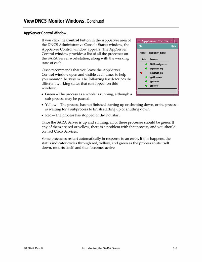
If you click the Control button in the AppServer area of the DNCS Administrative Console Status window, the AppServer Control window appears. The AppServer Control window provides a list of all the processes on the SARA Server workstation, along with the working state of each.
Cisco recommends that you leave the AppServer Control window open and visible at all times to help you monitor the system. The following list describes the different working states that can appear on this window: • Green—The process as a whole is running, although a
sub-process may be paused. • Yellow—The process has not finished starting up or shutting down, or the process
is waiting for a subprocess to finish starting up or shutting down. • Red—The process has stopped or did not start.
Once the SARA Server is up and running, all of these processes should be green. If any of them are red or yellow, there is a problem with that process, and you should contact Cisco Services.
Some processes restart automatically in response to an error. If this happens, the status indicator cycles through red, yellow, and green as the process shuts itself down, restarts itself, and then becomes active.
1-6 Introducing the SARA Server 4009747 Rev B
View DNCS Monitor Windows, Continued
SARA Server Processes Description
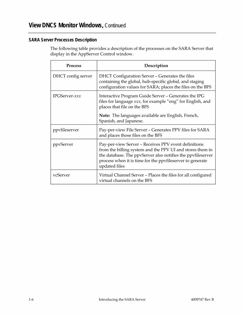
The following table provides a description of the processes on the SARA Server that display in the AppServer Control window.
Process Description
DHCT config server DHCT Configuration Server – Generates the files containing the global, hub-specific global, and staging configuration values for SARA; places the files on the BFS
IPGServer-xxx Interactive Program Guide Server – Generates the IPG files for language xxx, for example “eng” for English, and places that file on the BFS
Note: The languages available are English, French, Spanish, and Japanese.
ppvfileserver Pay-per-view File Server – Generates PPV files for SARA and places those files on the BFS
ppvServer Pay-per-view Server – Receives PPV event definitions from the billing system and the PPV UI and stores them in the database. The ppvServer also notifies the ppvfileserver process when it is time for the ppvfileserver to generate updated files
vcServer Virtual Channel Server – Places the files for all configured virtual channels on the BFS

4009747 Rev B Introducing the SARA Server 1-7
View DNCS Monitor Windows, Continued
DNCS Administrative Console Window
Frequently called the Admin Console, the DNCS Administrative Console is the window you use most often as you operate the SARA Server.

1-8 Introducing the SARA Server 4009747 Rev B
View DNCS Monitor Windows, Continued
DNCS Administrative Console Window Tabs
Each of the four primary tabs on the DNCS Admin Console provides access to specific functions.
You will use the Server Applications tab to provision SARA Server applications. For more information on using the other tabs in DNCS processes, refer to the Digital Network Control System (DNCS) Online Help for your system release.
The following table describes the specific functions of the primary tabs on the DNCS Admin Console.
Note: The options that appear on these tabs vary depending on the optional features you have installed on your system.
Tab Description
DNCS Allows you to provision basic digital services and manage DBDS hardware on the DNCS
Application Interface Modules
Allows you to set parameters for the DNCS to interact with DHCTs and service providers (for example, HBO or Internet services) to permit a smooth transfer of information between the service providers and DHCTs
Server Applications
Provides access to applications that reside on the SARA Server so that you can enable DHCTs to offer services associated with those applications to subscribers
Note: The options that appear on this tab vary depending on the applications available on your system.
Network Management
Provides access to network management windows, including the DHCT Monitor, so that you can monitor and manage activity on your system
4009747 Rev B Introducing the SARA Server 1-9
Online Help
Introduction
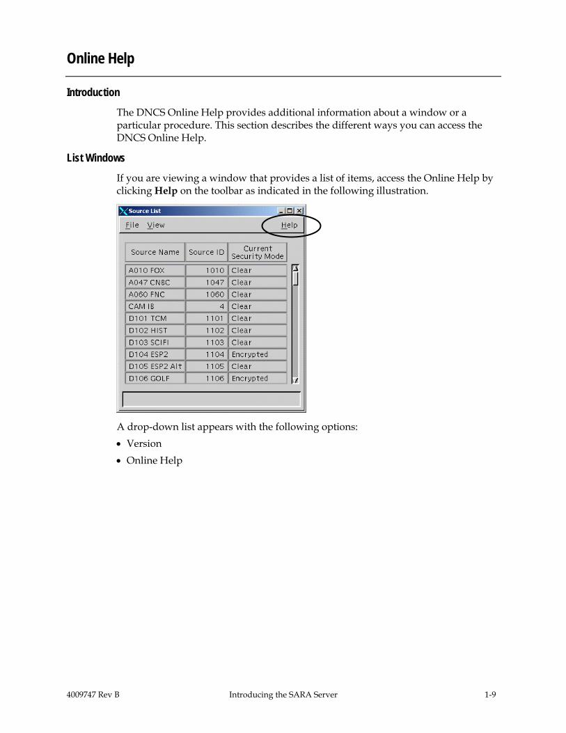
The DNCS Online Help provides additional information about a window or a particular procedure. This section describes the different ways you can access the DNCS Online Help.
List Windows If you are viewing a window that provides a list of items, access the Online Help by clicking Help on the toolbar as indicated in the following illustration.
A drop-down list appears with the following options: • Version • Online Help

1-10 Introducing the SARA Server 4009747 Rev B
Online Help, Continued
If you select Version, the system opens the Netscape Internet browser with a list of software versions installed on your DNCS workstation.
If you click Online Help, the system opens the DNCS Online Help in the Netscape Internet browser.

4009747 Rev B Introducing the SARA Server 1-11
Online Help, Continued
WUI Windows Provide Targeted Help Web-based User Interface (WUI) windows were introduced in SR 2.2 and 3.2. These windows display using a Web browser, such as Netscape. If you are viewing a WUI window, access the Online Help by clicking the Help link located in the left pane of the WUI window.
Note: As new DNCS windows are introduced, or old windows modified, they are converted to the new WUI format, which provides more flexibility.
The system opens a targeted page of the DNCS Online Help in the Netscape Internet browser, similar to the example shown here.

1-12 Introducing the SARA Server 4009747 Rev B
Online Help, Continued
Setup Windows Provide General Help If you are viewing a window that allows you to set up a network element, access the Online Help by clicking the Help button located at the bottom of the window as indicated in the following illustration.
The system opens the Welcome page of the DNCS Online Help in the Netscape Internet browser.

4009747 Rev B Introducing the SARA Server 1-13
Online Help, Continued
Finding Information
You can use any of the following methods to find information you need in the DNCS Online Help: • Click the topic in the Contents list • Click the Index tab and type a keyword • Click the Search tab and type a keyword • Click the Troubleshooting topic in the Contents list for help resolving errors you
may be experiencing • Click the Glossary topic at the bottom of the Contents list for definitions of terms
used throughout the Online Help
Conventions
At the beginning of most procedures in the DNCS Online Help is a Quick Path for getting to a specific GUI window to perform the procedure. The following example shows the Quick Path for opening the Source Definitions List window.
Quick Path: DNCS Administrative Console > DNCS tab > System Provisioning tab > Source > [Source Name] > File > Source Definitions
As you become more experienced in using the DNCS, these Quick Paths may be the only reminders you need of how to perform certain tasks. In this example, you would use the Quick Path to perform the following steps.
1. On the DNCS Administrative Console, click the DNCS tab.
2. On the DNCS tab, click the System Provisioning tab.
3. On the System Provisioning tab, click the Source button.
Result: The Source List window opens.
4. On the Source List window, click once on the source name ([Source Name]) whose definition you need.
5. Click on the File menu, and then select Source Definitions.
Result: The Source Definitions List window opens for the source you selected.

1-14 Introducing the SARA Server 4009747 Rev B
Online Help, Continued
Navigation Tips
The following tips may help you to navigate more efficiently around the DNCS and the Online Help: • To open a window for an existing item on the DNCS, the procedures in the Online
Help advise you to click once on the item name; then, click File and select Open. In most cases, you can simply double-click on the item name to open the window, if you prefer.
• To return to a Help topic you have previously visited, click Go on your browser toolbar, and then choose Back from the drop-down menu that appears. You can also click the right mouse button in the Help topic window and select Back from the menu that appears.
• Occasionally, a Help page may not display properly. This is especially true if you try to resize the Help window. If this happens, simply close the Online Help and then re-open it.
Search Tips
Entering a word or phrase in the Search tab and clicking Find explores the content of topics and finds all occurrences of the word or phrase. This method can help you find a topic (if you know its title) or every instance of a concept or feature in the system.
The following tips may help you to find topics more quickly: • Searches are not case-sensitive. You can type your search in uppercase characters,
lowercase characters, or a mix. • You may search for any combination of letters (a-z) and numbers (0-9). • To search for an exact phrase, surround the elements of your search with double
quotes. For example, to search for information about the window Set Up BFS Host, enter “Set Up BFS Host” in the search field. This ensures that the system looks for this exact phrase. On the other hand, entering Set Up BFS Host, in the search field causes the system to look for topics that contain any of these four words.
Printing Help Topics
If your system has print capabilities, you can print any Help topic by completing these steps.
1. Click once within the topic to select that area (frame).
2. Click File on your browser toolbar, and then select Print Frame from the menu.

4009747 Rev B Getting Started 2-1
Chapter 2 Getting Started
Overview
Introduction
This chapter provides procedures for starting up the SARA Server workstation and its processes. Use the procedures in this chapter if you are starting up the SARA Server for the first time or if power to the SARA Server has been interrupted.
Typically, the SARA Server operates continuously until you stop it manually to upgrade it. If you are upgrading the SARA Server, do not use the procedures in this chapter to restart the SARA Server after the upgrade. Instead, use the procedures provided in the appropriate upgrade installation instructions for your system release.
In This Chapter
This chapter contains the following topics.
Topic See Page
Power On the SARA Server Workstation 2-2
Start SARA Server Processes 2-3

2-2 Getting Started 4009747 Rev B
Power On the SARA Server Workstation
Before You Begin
Before you power on the SARA Server workstation, the DNCS processes must be running and you must have your login password. If you do not know your login password, see your system administrator.
Powering Up the SARA Server Workstation Complete these steps to power on the SARA Server workstation.
1. Go to the SARA Server workstation and press the Power button.
Result: The login window opens with a welcome message after a few minutes.
Note: If your system is not set up properly, the SARA Server will not finish powering up. If your SARA Server does not power on, Cisco Services.
2. Type the user name (typically dncs), and then press Enter.
Result: The password prompt appears.
3. Type the password, and then press Enter.
Result: The SARA Server desktop appears. The SARA Server workstation is now powered up.
4. Your next step is to start the SARA Server processes. Go to Start SARA Server Processes, next in this chapter.
4009747 Rev B Getting Started 2-3
Start SARA Server Processes
Introduction
After you power on the SARA Server workstation, you can start the SARA Server processes. These processes are an integral part of the SARA Server software. You cannot use the SARA Server with the DNCS until you start these processes.
Starting SARA Server Processes Complete these steps to start the SARA Server processes.
1. Use the mouse to place the cursor anywhere on the SARA Server desktop, and then click the middle mouse button.
Result: A dropdown menu appears with a list of options.
2. Click App Serv Start.
Result: The workstation front-panel “busy” light blinks to indicate that the software startup is in process.
Monitoring SARA Server Processes
If you want to monitor each SARA Server process as it starts, complete these steps.
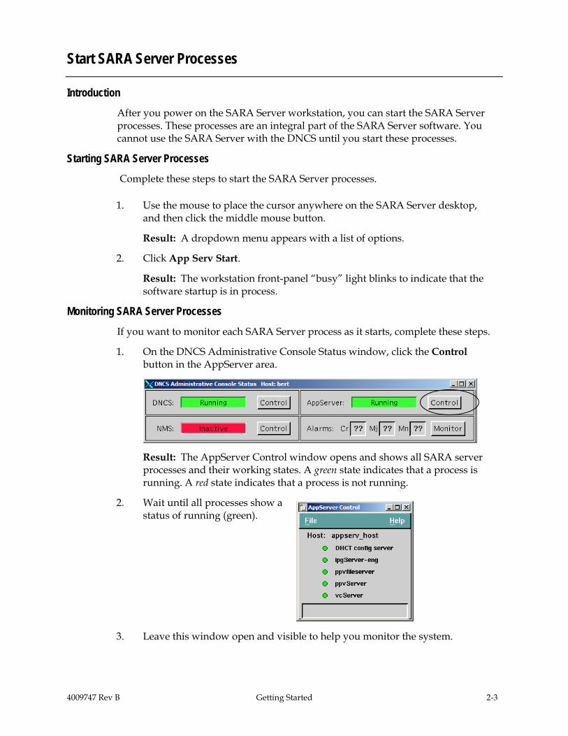
1. On the DNCS Administrative Console Status window, click the Control button in the AppServer area.
Result: The AppServer Control window opens and shows all SARA server processes and their working states. A green state indicates that a process is running. A red state indicates that a process is not running.
2. Wait until all processes show a status of running (green).
3. Leave this window open and visible to help you monitor the system.

2-4 Getting Started 4009747 Rev B
Start SARA Server Processes, Continued
What’s Next?
After you have verified that all of the processes are running properly, your next step is to set up the applications that you offer to your subscribers. For assistance, see the following chapters: • Chapters 3 through 6 contain procedures for defining the applications you offer
subscribers and changing the way the applications are defined. • Chapter 7 contains procedures for enabling and disabling tracing on the SARA
Server. • Chapter 8 contains procedures for enabling SARA server software to support the
DVD copying (burning) feature of Explorer set-top boxes that offer this feature.

4009747 Rev B Setting Up Language Support 3-1
Chapter 3 Setting Up Language Support
Overview
Introduction
The DBDS allows you to display PPV/IPPV event information menus and the Interactive Program Guide (IPG) in one of several languages. However, to provide this feature to subscribers, you must first set up the languages on the DNCS.
Important: • To provide IPG in a different language, your data provider must provide
programming information, such as titles in those languages. • To provide PPV/IPPV titles in a different language, the billing system must
provide this information as a part of the event definition.
This chapter explains how to set up those languages.
In This Chapter This chapter contains the following topics.
Topic See Page
Set Up Supported Languages 3-2

3-2 Setting Up Language Support 4009747 Rev B
Set Up Supported Languages
Introduction
To set up other languages for your IPG, use the Languages user interface located on the Server Applications tab of the DNCS Administrative Console. For each language that you set up, there must be an IPG server and an IPG collector to support the language. The DNCS allows one IPG server per active language. You must complete the following tasks when setting up supported languages.
1. Verify and select the appropriate languages your system supports.
2. Create a server and a collector for each language you select.
For procedures to create a server and a collector, see Set Up the IPG in Chapter 5 of this guide.
Verifying and Selecting the Appropriate Languages
Perform the following steps to verify that the DNCS recognizes the languages your DBDS supports.
1. On the DNCS Administrative Console, select the Server Applications tab.
2. Click Languages.
Result: The Supported Languages window opens.
Notes: • Standard DHCT code supports
English, French, and Spanish. • Special DHCT code is required to
support Japanese.
3. If the languages your DBDS supports are not selected, select them.
Note: In the example in step 2, only English is selected. However, if your system requires French or Spanish select those options as well, and then click Save.
4. Click Close to exit the Supported Languages window.

4009747 Rev B Defining PPV Services and Events 4-1
Chapter 4 Defining PPV Services and Events
Overview
Introduction
PPV services, like clear broadcasts, are always available to subscribers. Whenever subscribers tune to a PPV service channel, the channel displays a barker that advertises the PPV events that are available for purchase. For example, the Preview barker, which is shown in the example to the right, contains information about the event that is currently showing, along with its retail price.
There are no control package restrictions to prevent subscribers from accessing PPV service channels. Any subscriber can simply tune to a PPV service channel that advertises PPV events and order an event following the instructions in the on-screen barkers. However, to restrict viewing of content, subscribers can use Parental Control and Purchase PINs.
This chapter provides steps for creating, modifying, and deleting secure events and PPV events.
In This Chapter
This chapter contains the following topics.
Topic See Page
Define PPV Services 4-2
Understand Windows and Barkers 4-10
Define PPV Events 4-16
4-2 Defining PPV Services and Events 4009747 Rev B
Define PPV Services
Before You Begin
Before you can define PPV events for subscribers to purchase, you must define the PPV services that will deliver these events. A PPV service is an application that allows subscribers to purchase and view movies, concerts, or sporting events to be viewed at a certain time on a certain channel. A PPV event is any program (such as movie, concert, or sporting event) that a subscriber can purchase through a PPV service. If a subscriber has purchased the event that is currently playing on the PPV service, then the PPV service displays that event. If not, then the PPV service displays advertising, interstitials, or some other programming.
As with other services, you must complete the following tasks when defining a PPV service: • Add the service source to the DNCS. This task specifies which digital or analog
signal the DBDS will use to deliver the service to subscribers. • Define parameters for the service source. This task defines the attributes that
establish how the system will process service content. Also, this task includes building a session, which defines and allocates the resources that the source will use to deliver the service content.
• Encrypt the content coming from the service source. This task ensures that the content will only be available to authorized subscribers.
Before you can define PPV services, the service on which a PPV service is built must be registered with the Service Application Manager (SAM), Event Use Service, Subscription Service (if used), and Interstitial Service. These are described in more detail later in this section. The SAM is a table that identifies available services and their associated applications. The DNCS automatically registers the service with the SAM when you create the service, so you do not need to register an event’s service with the SAM.
This section describes the Set Up PPV Service window and explains how to create, modify, and delete PPV services (the applications that deliver PPV events).
4009747 Rev B Defining PPV Services and Events 4-3
Define PPV Services, Continued
Understanding the Set Up PPV Service Window
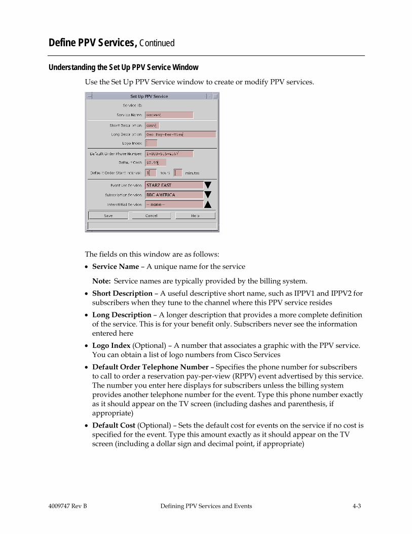
Use the Set Up PPV Service window to create or modify PPV services.
The fields on this window are as follows: • Service Name – A unique name for the service
Note: Service names are typically provided by the billing system. • Short Description – A useful descriptive short name, such as IPPV1 and IPPV2 for
subscribers when they tune to the channel where this PPV service resides • Long Description – A longer description that provides a more complete definition
of the service. This is for your benefit only. Subscribers never see the information entered here
• Logo Index (Optional) – A number that associates a graphic with the PPV service. You can obtain a list of logo numbers from Cisco Services
• Default Order Telephone Number – Specifies the phone number for subscribers to call to order a reservation pay-per-view (RPPV) event advertised by this service. The number you enter here displays for subscribers unless the billing system provides another telephone number for the event. Type this phone number exactly as it should appear on the TV screen (including dashes and parenthesis, if appropriate)
• Default Cost (Optional) – Sets the default cost for events on the service if no cost is specified for the event. Type this amount exactly as it should appear on the TV screen (including a dollar sign and decimal point, if appropriate)
4-4 Defining PPV Services and Events 4009747 Rev B
Define PPV Services, Continued
• Default Order Start Interval (Optional) – Specifies a default interval during which subscribers can call to order an event, if the event definition does not specify when subscribers can order the event. For example, suppose the Default Order Start Interval is 12 hours and 0 minutes. If an event does not specify an order start time, then subscribers can begin calling to order the event 12 hours before the event begins. Type this amount in hours and minutes
• Event Use Service – The service that will be seen on this PPV service when PPV events are purchased. Click the arrow () to display a list of all services available, and then select the appropriate service from the list
• Subscription Service (Optional) – Specifies whether this service will function as a subscription service in addition to a PPV service − If you want the service to function as a PPV service, click the arrow () and
select none − If you want the service to function as a subscription service (one that is always
available to authorized subscribers), click the arrow and select the same service you selected in the Event Use Service field
• Interstitial Service (Optional) – A specific service that displays between events; this service could be general programming or an advertisement. Click the arrow and select from the list of existing services. If you do not specify an interstitial service, the PPV service channel will display a standard text barker between events

4009747 Rev B Defining PPV Services and Events 4-5
Define PPV Services, Continued
Creating a PPV Service
After you have built the services, the next step is to create a service that advertises and sells the events: a PPV service.
Complete these steps to create a PPV service.
1. On the DNCS Administrative Console, select the Server Applications tab.
Result: The Server Applications tab moves to the forefront.
2. Click PPV Service.
Result: The PPV Service List window opens.
4-6 Defining PPV Services and Events 4009747 Rev B
Define PPV Services, Continued
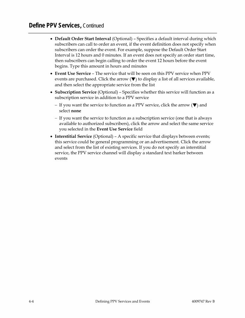
3. From the File menu, click New. Result: The Set Up PPV Service window opens.
4. On the Set Up PPV Service window, complete all of the following required
fields. Optional fields are labeled. • Service Name • Short Description • Long Description • Logo Index (Optional) • Default Order Telephone Number • Default Cost (Optional) • Default Order Start Interval (Optional) • Event Use Service • Subscription Service (Optional) • Interstitial Service (Optional)
Notes: • See Understanding the Set Up PPV Service Window on page 4-3 for
descriptions of these fields. • Be sure to make a note of the values in the Short Description field and the
Event Use Service field. You will need these values when you set up this PPV service on the IPG.

4009747 Rev B Defining PPV Services and Events 4-7
Define PPV Services, Continued
5. Click Save.
Result: The SARA Server creates a PPV service for the source and automatically does the following: • Registers the service with the SAM • Assigns a URL of ippv to the service • Makes the service available to the channel maps • Creates an unlimited segment from the service, which you can view in the
Segment List
Result: For each PPV service there are two SAM services: the PPV service and the Event Use service. You must map both the PPV service and the Event Use service to the IPG Service List to ensure that data about the events appears in the IPG and on the purchase barkers.
6. Do you want to add another PPV service? • If yes, go back to step 3 and add the next service. • If no, go to step 7.
7. Add all of the PPV services that you created and all of their Event Use services to the IPG Service List. For assistance, go to Set Up the IPG in Chapter 5 and follow the instructions.
8. Add all of the PPV services that you created to the channel map. Refer to the Digital Network Control System Online Help (UNIX) Version for your system release, for procedures to complete this task.
9. Does your system support Explorer® 3100HD™ DHCTs? • If yes, ensure that the SAM URL of any PPV service that contains high-
definition (HD) content includes the HD flag. If this flag is absent in HD content, 3100HD DHCTs cannot display PPV barkers and other graphics over HD content. As a result, full-screen HD content displays over PPV preview graphics and enables subscribers to receive the entire HD event for free. For assistance adding the HD flag to the SAM URL of HD PPV services, refer to Enhancing Your Subscribers’ Experience: SARA Configurable Options, User’s Guide.
Note: The HD flag (;HD) must be attached to the end of the SAM Service URL (on the Set Up SAM Service window) as shown in this example: bfs://resapp/watchtv;HD.
• If no, you have completed defining PPV services. For a better understanding of how PPV events are offered to subscribers, see Understand Windows and Barkers.

4-8 Defining PPV Services and Events 4009747 Rev B
Define PPV Services, Continued
Modifying PPV Services Complete these steps to modify a PPV service.
1. On the PPV Service List window, highlight the row of the desired service.
2. Click the File menu and select Open.
Result: The Set Up PPV Service window opens.
3. Make necessary changes in the fields, and click Save.

4009747 Rev B Defining PPV Services and Events 4-9
Define PPV Services, Continued
Deleting a PPV Service Complete these steps to delete a PPV service.
Important: The system will not allow you to delete a service if events also use the service.
1. Select the service you want to delete in the PPV Service list window.
2. Click the File menu and select Delete.
Result: A Question window opens, prompting you to confirm that you want to delete the current item.
3. Click Yes to confirm that you want to delete the PPV service.

4-10 Defining PPV Services and Events 4009747 Rev B
Understand Windows and Barkers
Introduction
PPV events are available for viewing during a specified period of time. This period of time is called a window. The period of time that a window is present determines when the PPV service displays a specific type of advertisement or purchase option. These advertisements and purchase options are presented by screens called barkers.
This section describes the types of windows and barkers used in offering PPV events to subscribers. You must understand the relationship between windows and barkers in order to define PPV events successfully.
Note: Remember a window is a period of time. A barker is a screen that advertises an event or allows a subscriber to order an event.
4009747 Rev B Defining PPV Services and Events 4-11
Understand Windows and Barkers, Continued
Windows
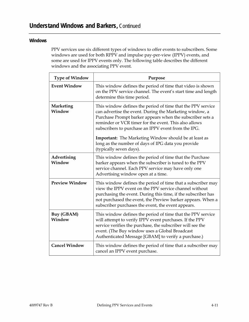
PPV services use six different types of windows to offer events to subscribers. Some windows are used for both RPPV and impulse pay-per-view (IPPV) events, and some are used for IPPV events only. The following table describes the different windows and the associating PPV event.
Type of Window Purpose
Event Window This window defines the period of time that video is shown on the PPV service channel. The event’s start time and length determine this time period.
Marketing Window
This window defines the period of time that the PPV service can advertise the event. During the Marketing window, a Purchase Prompt barker appears when the subscriber sets a reminder or VCR timer for the event. This also allows subscribers to purchase an IPPV event from the IPG.
Important: The Marketing Window should be at least as long as the number of days of IPG data you provide (typically seven days).
Advertising Window
This window defines the period of time that the Purchase barker appears when the subscriber is tuned to the PPV service channel. Each PPV service may have only one Advertising window open at a time.
Preview Window This window defines the period of time that a subscriber may view the IPPV event on the PPV service channel without purchasing the event. During this time, if the subscriber has not purchased the event, the Preview barker appears. When a subscriber purchases the event, the event appears.
Buy (GBAM) Window
This window defines the period of time that the PPV service will attempt to verify IPPV event purchases. If the PPV service verifies the purchase, the subscriber will see the event. (The Buy window uses a Global Broadcast Authenticated Message [GBAM] to verify a purchase.)
Cancel Window This window defines the period of time that a subscriber may cancel an IPPV event purchase.

4-12 Defining PPV Services and Events 4009747 Rev B
Understand Windows and Barkers, Continued
Window Relationships
There are some timing requirements that you must follow when setting up PPV windows. If you do not follow these requirements, then subscribers may not be able to purchase PPV events successfully. For example, if you do not define an Advertising window correctly, then the Purchase barker will not appear when subscribers tune to the PPV service channel. In this case, subscribers are unable to purchase the event. Or, if you do not define the event itself correctly, then the event will not appear as expected.
In examining the window relationships in the following illustration, remember that the billing system defines these windows when it sends the event definition to the SARA Server. Therefore, in most cases you should not need to define an event (although you can do so manually if necessary.) You can view the Set Up PPV Event window to view the window definitions for an event.
Note: For IPPV events, you must define the Marketing, Advertising, Buy (GBAM), and Event windows. For RPPV events, you only need to define three windows: the Marketing, Advertising, and Event windows.
4009747 Rev B Defining PPV Services and Events 4-13
Understand Windows and Barkers, Continued
Barkers
A barker is often associated with a specific window. PPV uses three kinds of barkers. These barker types are as follows: • Purchase Prompt barker – This barker prompts subscribers to buy an event when
the subscriber performs one of the following actions: − Sets the VCR timer to record an event that has not yet occurred − Uses a reminder timer to notify the subscriber of an event to view in the future Subscribers can dismiss this barker by pressing the C key on the remote control. This barker appears during the Marketing window.
• Purchase barker – This barker advertises the next event available for purchase. This barker appears until the subscriber buys the event, selects a different channel, or views the Advertising window.
• Preview barker – This barker is similar to the Purchase barker. In addition to displaying information about the event, the Preview barker also displays a portion of the event as part of the advertisement.
Note: The Purchase Prompt barker and the Purchase barker appear for both RPPV and IPPV events. The Preview barker appears only for IPPV events.

4-14 Defining PPV Services and Events 4009747 Rev B
Understand Windows and Barkers, Continued
PPV Advertising Window Defaults
By default, the advertising window starts 15 minutes before an event starts and ends 45 minutes after an event starts. These values are called the start offset and the end offset. Cisco suggests that you adjust these values if you frequently have events that are less than 60 minutes long.
Before you adjust these offsets, you must identify the length of the shortest event that you will advertise. The length of your shortest event is your minimum event interval. Use the minimum event interval and the following guidelines to determine the new default values for your offsets: • The total offset time (start offset plus end offset) must not exceed your minimum
event interval. For example, if your shortest event is 30 minutes long, then the start offset plus the end offset must not exceed 30 minutes.
• For IPPV events, the purchase window cannot start before the advertising window starts.
• The advertising window must end at least 5 minutes before the end of the event.
The following table shows two examples of minimum event intervals and identifies acceptable default values for the start offset and the end offset:
Minimum Event Interval
Advertising Window Start Offset
Advertising Window End Offset
30 minutes 10 minutes 15 minutes
59 minutes 15 minutes 35 minutes

4009747 Rev B Defining PPV Services and Events 4-15
Understand Windows and Barkers, Continued
Modifying Default Values for PPV Advertising Windows
After you determine the default offset values for the Advertising Window, follow these steps to adjust those values:
1. Open an xterm window on the SARA Server.
2. Type cd /export/home/dncs and press Enter.
Result: The /export/home/dncs directory is now the working directory.
3. Type vi .profile and press Enter.
Note: Be sure to type a period (.) before the word “profile.”
Result: The vi editor opens the .profile file for editing.
4. Use the arrow keys to move to the bottom of the file.
5. Type o.
Result: A new line appears at the end of the file.
6. Type the following lines at the end of the file and press Enter after each line.
export PPV_ADV_WIND_START_INTVL=[number of seconds for new default start offset]
export PPV_ADV_WIND_END_INTVL=[number of seconds for new default end offset]
Examples:
PPV_ADV_WIND_START_INTVL=600
PPV_ADV_WIND_END_INTVL=900
7. Type :wq and press Enter.
Result: The vi editor saves and closes the .profile file.
8. On the SARA Server, run the appControl utility, and then stop and restart the PPV processes to activate these new values.

4-16 Defining PPV Services and Events 4009747 Rev B
Define PPV Events
Types Of Events (RPPV vs. IPPV)
The billing system defines the following two types of events based on how subscribers purchase them: • RPPV event—Subscribers can purchase an RPPV event by placing a telephone call.
A cable service representative (or an automated service) may order the event for the subscriber.
• IPPV event—Subscribers can purchase an IPPV event by using the remote control keys to purchase the event.
Note: After you define an event, you should use a DHCT in the headend to confirm that the event is available for ordering. By doing so, you can verify that the PPV service and the PPV event were defined correctly.
Generating PPV Events Automatically
Typically, the billing system defines PPV events automatically. However, a solid understanding of how the billing system defines PPV events makes it easier for you to correct any errors that may occur
Whether the billing system defines an event automatically, or you define one manually using the SARA Server, either action generates an ECM (Entitlement Control Message). An ECM associates a package with the event and assigns an EID (Event ID) to the package. (Packages collect program segments into offerings that are meaningful to the subscriber and hold potential profitability for the MSO.)
Note: If you are generating IPPV events for a test lab, you can use the genPpvFromIpg utility to create PPV events using existing IPG data. The utility works by reformatting existing IPG data in the database into PPV data. For details, refer to the Application Server Utilities User’s Guide. However, this utility is designed for use in test labs only. Do not run this utility on a live system.
The billing system automatically generates PPV events as follows:
1. The billing system sends event definition to the SARA Server.
2. The SARA Server processes the definition and sends it to the DNCS for packaging.
3. Using the definition, the DNCS issues an ECM for the event. As part of issuing the ECM, the DNCS creates a package for the event and assigns the package an EID.
4. The DNCS transmits the ECM to a router, and the router forwards the ECM to the appropriate program QAM modulator.

4009747 Rev B Defining PPV Services and Events 4-17
Define PPV Events, Continued
Generating RPPV Events Manually Perform the following steps to create an RPPV event.
1. On the DNCS Administrative Console, select the Server Applications tab.
2. Click PPV Event. Result: The PPV Event List window opens. Typically you would open an event from this list to examine one already defined by the billing system. However, because you are setting up events manually, create a new event by selecting New from the File menu.
3. Click the File menu and select New.
Result: The Set Up PPV Event window opens. The window has two tabs that allow the user to access different data entry fields: the Package Info and Event Info tabs. Start by entering information into the Package Info tab to define the package that contains the event.

4-18 Defining PPV Services and Events 4009747 Rev B
Define PPV Events, Continued
4. Select the Package Info tab.
5. In the top section of the tab, type the following information into their respective fields: • Package Name – A name for the package • Start Date – The date when the package starts in MM/DD/YY format • Start Time – The time when the package starts in HH:MM:SS format.
Select AM or PM • Length – The length of the package in days, hours, and minutes
6. Select the Reservation Pay Per View option.
7. If you want subscribers to have the right to copy the event, select the Allowed option.
8. Select the Event Info tab.
4009747 Rev B Defining PPV Services and Events 4-19
Define PPV Events, Continued
9. In the top section of the tab, type the following information into their respective fields: • Service Name – Click the down arrow and select the appropriate PPV
service that advertises this event. • Retail Price – The price of the event. If entered, the price appears on the
subscriber’s IPG. Type this price exactly as it should appear on the IPG, including dollar sign and decimal, if appropriate.
• English Event Title – The title of the event. The title appears during the Advertising, Purchase, and Preview windows.
• Phone Number – The telephone number subscribers can call to order the event. Type this number exactly as it should appear on the IPG, including parentheses and dashes, if appropriate.
• Start Date – The date on which the event is to begin. Type this date in the format MMDDYY. Do not type slashes in this date. This date must be in the future.
• Start Time - The time at which the event is to begin. Type this time in the format HHMM. Do not type colons in this time. Must be at least 15 minutes in the future. Select AM or PM.
10. If you choose the Specify Advertising Window and Specify Marketing Window options, then enter the data defining how these windows function in their fields on the respective tabs. Otherwise, the SARA Server applies the defaults to the data in these fields when you save the changes.
Note: These windows let you specify the start date, start time, and duration for the advertising window or marketing window.
11. Click Save when you finish entering all the data.
Note: The Set Up PPV Event window disappears and the SARA Server saves your changes.
12. Verify that the source you created now appears in the PPV Service List window and that the source information is correct.
4-20 Defining PPV Services and Events 4009747 Rev B
Define PPV Events, Continued
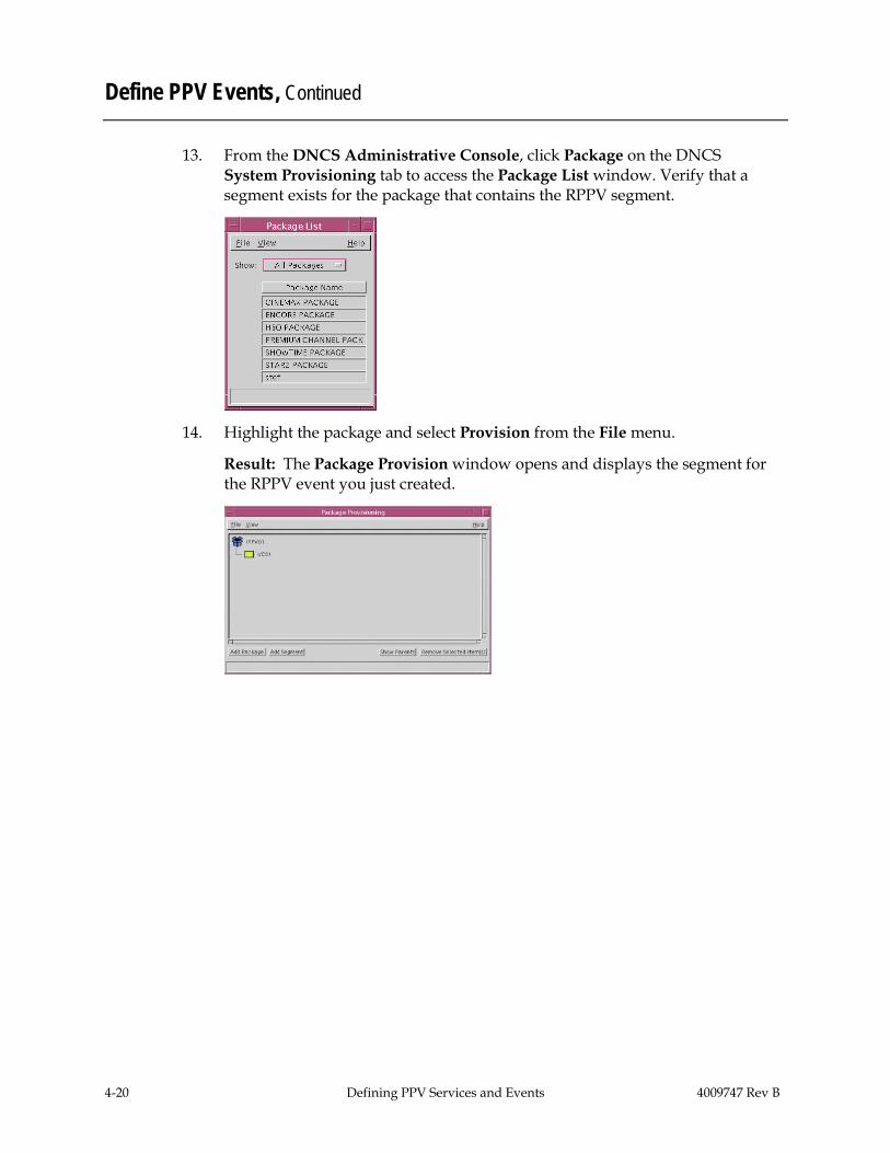
13. From the DNCS Administrative Console, click Package on the DNCS System Provisioning tab to access the Package List window. Verify that a segment exists for the package that contains the RPPV segment.
14. Highlight the package and select Provision from the File menu.
Result: The Package Provision window opens and displays the segment for the RPPV event you just created.

4009747 Rev B Defining PPV Services and Events 4-21
Define PPV Events, Continued
Generating IPPV Events Manually
Setting up an IPPV event is similar to setting up an RPPV event. However, to set up an IPPV event you must present a method for subscribers to purchase the event on their own. The following procedure provides instructions to set up an IPPV event manually.
Perform the following steps to create an IPPV event.
1. On the DNCS Administrative Console, select the Server Applications tab.
2. Click PPV Event.
Result: The PPV Event List window opens. Typically you would open an event from this list to examine one already defined by the billing system. However, because you are setting up events manually, create a new event by selecting New from the File menu.

4-22 Defining PPV Services and Events 4009747 Rev B
Define PPV Events, Continued
3. Click the File menu and select New.
Result: The Set Up PPV Event window opens. The window has two tabs that allow the user to access different data entry fields: the Package Info and Event Info tabs. Start by entering information into the Package Info tab to define the package that contains the event.
4. Select the Package Info tab.
5. In the top section of the tab, type the following information into their respective fields: • Package Name – A name for the package • Start Date – The date when the package starts in MM/DD/YY format • Start Time – The time when the package starts in HH:MM:SS format.
Select AM or PM • Length – The length of the package in days, hours, and minutes

4009747 Rev B Defining PPV Services and Events 4-23
Define PPV Events, Continued
6. Select the Impulse Pay Per View option.
Result: The Preview, Buy Window, and Purchase Mode tabs become active.
7. Complete the fields on these tabs with data that defines how the windows function. Follow the rules of window relationships as outlined in the Understand Windows and Barkers section, earlier in this chapter. Otherwise, the SARA Server applies the defaults to the data in these fields when you save it.
Notes: • You can also set up a dual RPPV/IPPV event by selecting both
Reservation Pay Per View and Impulse Pay Per View options. Then, complete the fields in the Set Up PPV Event window for both types of events.
• When you set up a dual RPPV/IPPV event, DHCTs that can purchase IPPV events will display IPPV advertisements for the event, and subscribers will be able to use their remote controls to purchase the event. DHCTs that can purchase RPPV events will display a telephone number that prompts subscribers to phone in an order for an event.
4-24 Defining PPV Services and Events 4009747 Rev B
Define PPV Events, Continued
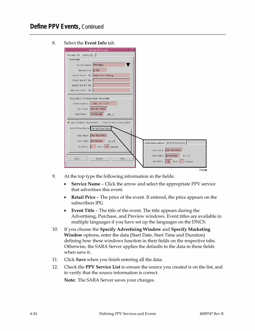
8. Select the Event Info tab.
9. At the top type the following information in the fields:
• Service Name – Click the arrow and select the appropriate PPV service that advertises this event.
• Retail Price – The price of the event. If entered, the price appears on the subscribers IPG
• Event Title – The title of the event. The title appears during the Advertising, Purchase, and Preview windows. Event titles are available in multiple languages if you have set up the languages on the DNCS.
10. If you choose the Specify Advertising Window and Specify Marketing Window options, enter the data (Start Date, Start Time and Duration) defining how these windows function in their fields on the respective tabs. Otherwise, the SARA Server applies the defaults to the data in these fields when save it.
11. Click Save when you finish entering all the data. 12. Check the PPV Service List to ensure the source you created is on the list, and
to verify that the source information is correct. Note: The SARA Server saves your changes.
4009747 Rev B Defining PPV Services and Events 4-25
Define PPV Events, Continued
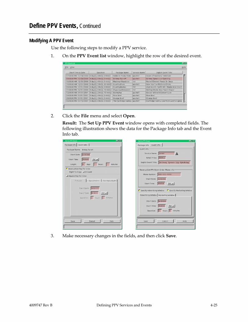
Modifying A PPV Event Use the following steps to modify a PPV service.
1. On the PPV Event list window, highlight the row of the desired event.
2. Click the File menu and select Open. Result: The Set Up PPV Event window opens with completed fields. The following illustration shows the data for the Package Info tab and the Event Info tab.
3. Make necessary changes in the fields, and then click Save.
4-26 Defining PPV Services and Events 4009747 Rev B
Define PPV Events, Continued
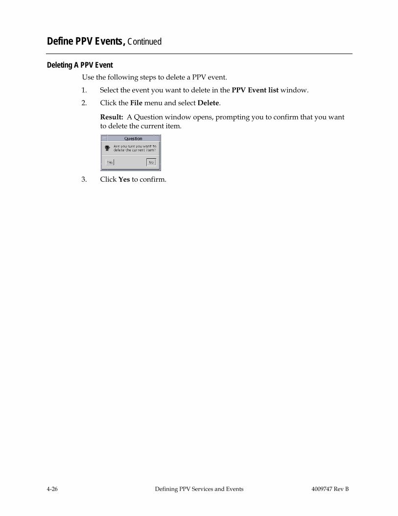
Deleting A PPV Event Use the following steps to delete a PPV event.
1. Select the event you want to delete in the PPV Event list window.
2. Click the File menu and select Delete.
Result: A Question window opens, prompting you to confirm that you want to delete the current item.
3. Click Yes to confirm.
4009747 Rev B Setting Up the Interactive Program Guide 5-1
Chapter 5 Setting Up the Interactive Program Guide
Overview
Introduction
The IPG is an application that DHCTs use to display program information, such as the program name, start and end times, description, and rating. When you set up the IPG, the DNCS populates the IPG with data such as program listings and program descriptions. SARA provides other information on the IPG such as instructional text (for example, the words Browse By and Choose Date) and other General Settings menus. If you do not set up the IPG correctly, the IPG appears with no program information, even when a subscriber selects the Guide button.
IPG data is linked to a specific program service using the IPG service provider’s designation and the SAM service ID number. This link ensures that information and program descriptions are matched to the correct services.
This chapter provides procedures for setting up the IPG.
In This Chapter
This chapter contains the following topics.
Topic See Page
Before You Begin 5-2
Set Up the IPG 5-5
Edit IPG Data 5-15
5-2 Setting Up the Interactive Program Guide 4009747 Rev B
Before You Begin
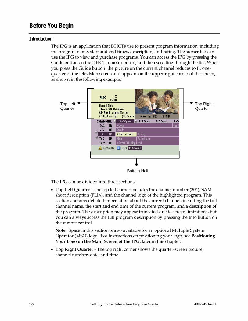
Introduction The IPG is an application that DHCTs use to present program information, including the program name, start and end times, description, and rating. The subscriber can use the IPG to view and purchase programs. You can access the IPG by pressing the Guide button on the DHCT remote control, and then scrolling through the list. When you press the Guide button, the picture on the current channel reduces to fit one-quarter of the television screen and appears on the upper right corner of the screen, as shown in the following example.
The IPG can be divided into three sections:
• Top Left Quarter - The top left corner includes the channel number (304), SAM short description (FLIX), and the channel logo of the highlighted program. This section contains detailed information about the current channel, including the full channel name, the start and end time of the current program, and a description of the program. The description may appear truncated due to screen limitations, but you can always access the full program description by pressing the Info button on the remote control.
Note: Space in this section is also available for an optional Multiple System Operator (MSO) logo. For instructions on positioning your logo, see Positioning Your Logo on the Main Screen of the IPG, later in this chapter.
• Top Right Quarter - The top right corner shows the quarter-screen picture, channel number, date, and time.
Top Left Quarter
Top Right Quarter
Bottom Half
4009747 Rev B Setting Up the Interactive Program Guide 5-3
Before You Begin, Continued
• Bottom Half - The bottom half of the screen shows the listings for several channels arranged in chronological order. The strip along the bottom of the screen identifies the date for these listings and indicates the way these listings are arranged (“by time” in this example). Pressing the button lets you browse these listings alphabetically by title or by theme, and pressing the button lets you view listings for a different date. In addition, if you press the Info button, this section of the screen displays more detailed information about the highlighted program.
Collecting the IPG Data In order to provide IPG data you must set up IPG collectors and IPG servers, and you must map IPG data to SAM services. The IPG collectors receive IPG data through the data provider’s File Transfer Protocol (FTP) Web site. This data is stored in a provider-neutral format in the SARA Server database.
For each IPG collector, there must be an IPG server. The IPG servers pull data from the DNCS database and create files on the Broadcast File System (BFS). The DHCTs can then download data as needed.

5-4 Setting Up the Interactive Program Guide 4009747 Rev B
Before You Begin, Continued
The following table lists and describes the information you must have in order to set up each IPG collector.
IPG Data Required Description
The IPG service provider
Specifies the format in which to provide data to the subscriber. Cisco supports three formats: TV Data, On TV, and CISCO COMP (Cisco Compatible) formats
Host Name Specifies the FTP site from which to retrieve the data. The host name can be a standard Web name, such as ftp.tvdata.com if the SARA Server uses Domain Name Service (DNS), or a raw IP address such as 204.97.140.250
User Name Specifies your user name. The IPG data provider will give you this name.
Password Specifies your password. The IPG data provider will give you this password
Pickup Directory or Data file location
Specifies the directory from which to retrieve data files. The IPG data provider will give you this directory.
File Template Specifies the naming convention of the file to be retrieved
Collection Time Specifies the time the IPG collector will collect new data from the data provider
Service Names Specifies the service names used by the content provider.
Logo File If using a logo, the logo file must be present on the DNCS. For more information, see Add a File Containing Your Company’s Logo to the BFS, later in this section.

4009747 Rev B Setting Up the Interactive Program Guide 5-5
Set Up the IPG
Introduction
The process for setting up IPG services includes the following tasks: • Selecting languages that subscribers can choose to display IPG data • Setting up the IPG servers for each language • Setting up IPG collectors for each language • Setting up the IPG services
This section also includes procedures to modify and delete IPG Service names.
If you provide IPG data in foreign languages, you must set up the languages for the IPG data before you set up the IPG. When you first install your system, the IPG is available in at least one language. For the DNCS to allow you to create additional IPG servers and collectors, you must first select the languages that you offer.
SR 2.5 and later, SR 3.5 and later, and SR 4.0 and later provide support for IPG data in English, French, Spanish, and Japanese. For detailed instructions on setting up support for foreign languages, see Set Up Supported Languages in Chapter 3 of this guide.

5-6 Setting Up the Interactive Program Guide 4009747 Rev B
Set Up the IPG, Continued
Setting Up IPG Servers The IPG server is not a physical server. Instead, it is a process named ipgServer that resides on the SARA Server. The IPG server uses the IPG information in the database to create IPG data files. The DBDS uses these IPG data files to display program information in the IPG. Use the following steps to set up IPG servers.
1. On the Server Applications tab, click IPG.
Result: The IPG Server List window opens.
2. Click the File menu and select New Server. Result: If you selected a language that does not yet have an IPG server, the following Set Up IPG Server window opens.
Note: If all languages already have IPG servers, the following message appears in the bottom pane of the IPG Server List window: No Languages found.
3. Click the Language arrow and select the language from the list. Note: The Supported Languages that you selected earlier appear in the list.
4009747 Rev B Setting Up the Interactive Program Guide 5-7
Set Up the IPG, Continued
4. Type the appropriate information for the following fields: • Produce Data for … days (typical choice is 7) • Send Schedule File Out-of-band for … days (typical choice is 2)
CAUTION:
The BFS requires a lot of bandwidth to send IPG data out of band. If you schedule out-of-band data for more than 2 days, you may cause the BFS Server to function incorrectly and disrupt service to subscribers.
5. Click Save.
Result: The IPG Server List window opens again and lists the new IPG language server you just added.
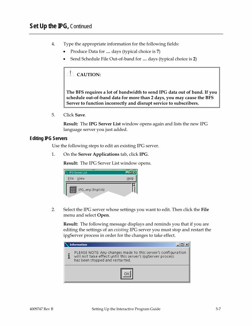
Editing IPG Servers Use the following steps to edit an existing IPG server.
1. On the Server Applications tab, click IPG.
Result: The IPG Server List window opens.
2. Select the IPG server whose settings you want to edit. Then click the File menu and select Open.
Result: The following message displays and reminds you that if you are editing the settings of an existing IPG server you must stop and restart the ipgServer process in order for the changes to take effect.
5-8 Setting Up the Interactive Program Guide 4009747 Rev B
Set Up the IPG, Continued
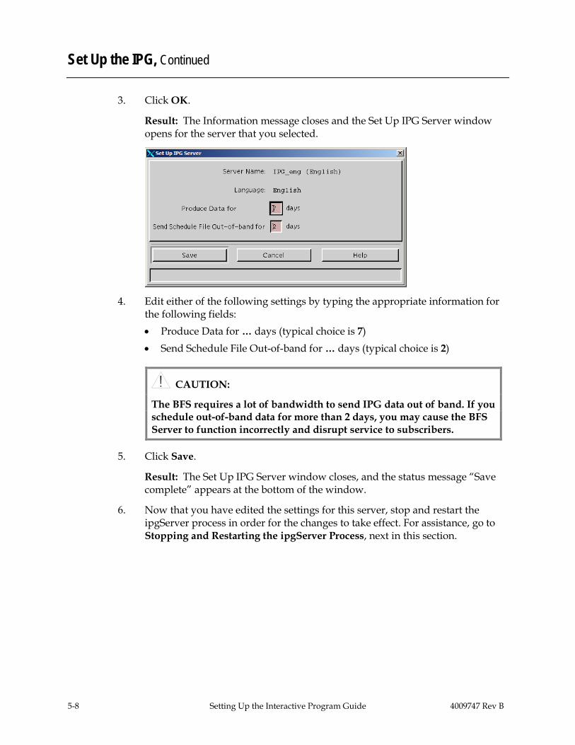
3. Click OK.
Result: The Information message closes and the Set Up IPG Server window opens for the server that you selected.
4. Edit either of the following settings by typing the appropriate information for the following fields: • Produce Data for … days (typical choice is 7) • Send Schedule File Out-of-band for … days (typical choice is 2)
CAUTION:
The BFS requires a lot of bandwidth to send IPG data out of band. If you schedule out-of-band data for more than 2 days, you may cause the BFS Server to function incorrectly and disrupt service to subscribers.
5. Click Save.
Result: The Set Up IPG Server window closes, and the status message “Save complete” appears at the bottom of the window.
6. Now that you have edited the settings for this server, stop and restart the ipgServer process in order for the changes to take effect. For assistance, go to Stopping and Restarting the ipgServer Process, next in this section.

4009747 Rev B Setting Up the Interactive Program Guide 5-9
Set Up the IPG, Continued
Stopping and Restarting the ipgServer Process
If you have changed the settings of an existing IPG server, you must stop and restart the ipgServer process in order for your changes to take effect.
Use the following steps to stop and restart the ipgServer process.
1. Open an xterm window on the SARA server and log in as dncs user.
2. Type appControl, and press Enter.
Result: The Applications Control window opens.
3. Type 2 (for Startup/Shutdown Single Element Group), and press Enter.
Result: The Applications Control window displays a numbered list of SARA server servers and processes.

5-10 Setting Up the Interactive Program Guide 4009747 Rev B
Set Up the IPG, Continued
4. Type the number associated with the IPG Server, and press Enter.
Result: The Applications Control window prompts you to enter a target status for the selected element group.
5. Type 1 (for stopped) and press Enter.
Result: The Applications Control window displays a confirmation message.
6. Type y (for yes) and press Enter.
Result: The Applications Control window refreshes.
Note: The Applications Control window refreshes in real time, or you can press Enter to force a refresh.
7. Wait until Curr Stt (for current state) of the IPG Server indicates stopped.
8. Type the number associated with the IPG Server, and press Enter.
Result: The Applications Control window prompts you to enter a target status for the selected element group.
9. Type 2 (for running) and press Enter.
Result: The Applications Control window displays a confirmation message.
4009747 Rev B Setting Up the Interactive Program Guide 5-11
Set Up the IPG, Continued
10. Type y (for yes), and press Enter.
Result: The Applications Control window refreshes.
Note: The Applications Control window refreshes in real time, or you can press Enter to force an immediate refresh.
11. Wait until Curr Stt (for current state) of the IPG Server indicates running.
12. Follow the on-screen instructions to return to the main menu and exit from the appControl utility.
Setting Up the IPG Collector
The IPG collector is a process that resides on the SARA Server. The IPG collector automatically runs once a day to retrieve IPG data from the IPG data provider.
Use the following steps to set up IPG collectors.
1. On the IPG Server List window, highlight the desired language server.
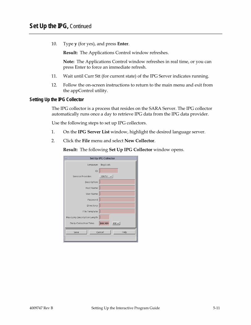
2. Click the File menu and select New Collector.
Result: The following Set Up IPG Collector window opens.

5-12 Setting Up the Interactive Program Guide 4009747 Rev B
Set Up the IPG, Continued
3. Complete all the fields by typing the required information, and click Save.
Important: Leave the Max Long Description Length set to its default value of 240.
Notes: • The cable service provider and the IPG data provider supply all the
information for these fields, for example, the user name and password, file template, and retrieval directory. The server updates data sent to DHCTs at midnight. Therefore, the collection time should be set as late as possible, but early enough for collection to finish before midnight.
• When you set up the IPG collector, it is a good idea to ping the IPG provider’s site to make sure that you can connect to the provider’s site.
• Occasionally, a ping may not work. In this instance, use the command ftp <site IP address or site name> to verify that the site can communicate with the IPG data provider.
4. On the Password Prompt window that opens, retype the password, and then click Continue.
Result: The system confirms the password, and then the IPG Server List window opens again.
Setting Up IPG Services After setting up the languages, IPG server, and IPG collector, you are ready to set up the IPG Service. Perform the following steps to set up IPG Services.
Note: To set up IPG Services, you will use the service name list from your content provider and map the service names to SAM Service IDs.
1. On the IPG Server List window, click the File menu and select Services.
Result: The IPG Service List window opens.

4009747 Rev B Setting Up the Interactive Program Guide 5-13
Set Up the IPG, Continued
2. Click the File menu and select New.
Result: The Set Up IPG Service window opens.
3. Type the IPG Provider Service Name and the SAM Service ID in their
respective fields.
Notes: • The SAM Service ID is the ID number assigned by the DNCS when the
service was registered with the SAM. For more information on registering services with the SAM, refer to the Digital Network Control System Online Help for your system release.
• Service IDs for all services are shown in the SAM Services List window. • For each PPV service that you set up, you must enter both the PPV service
and the Event Use service into the IPG service list. If you do not enter both services, information about the event will be missing in the IPG grid or in the PPV purchase barker. The PPV service ID displays event information in the IPG grid. The Event Use service ID displays event information in the PPV purchase barker.
4. Click Save. 5. Click the File menu and select Close.
5-14 Setting Up the Interactive Program Guide 4009747 Rev B
Set Up the IPG, Continued
Modifying an IPG Service Name Perform the following steps to modify an IPG service name.
Important: The IPG service names should match the names that your data provider uses in the IPG collector file.
1. Highlight the desired IPG server in the IPG Server List window. 2. Click the File menu and select Services. 3. On the IPG Service List window, highlight the row of the desired IPG
service. 4. Make changes to the IPG Provider Service Name, and click Save.
Note: You can only change the IPG Provider service name. You cannot change the SAM service ID.
Deleting an IPG Service Name
Perform the following steps to delete an IPG service name. 1. Select the IPG server you want to delete in the IPG Server List window. 2. Click the File menu and select Services. 3. On the IPG Service List window, highlight the row of the desired IPG
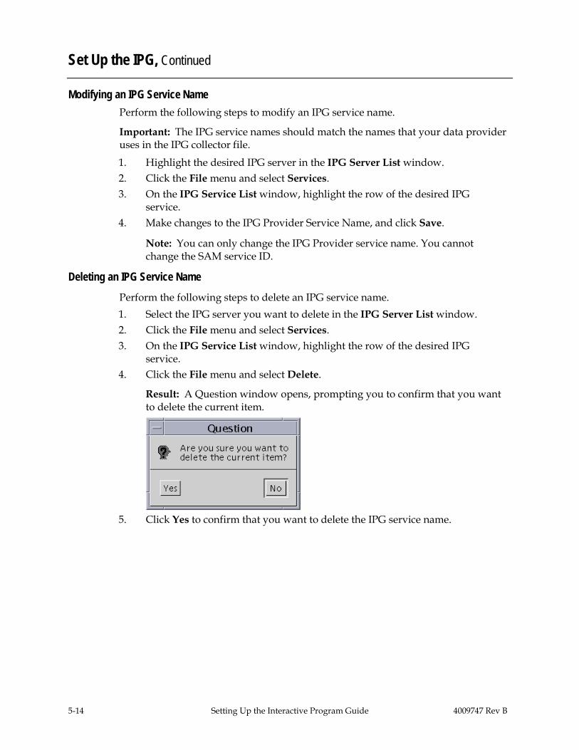
service. 4. Click the File menu and select Delete.
Result: A Question window opens, prompting you to confirm that you want to delete the current item.
5. Click Yes to confirm that you want to delete the IPG service name.
4009747 Rev B Setting Up the Interactive Program Guide 5-15
Edit IPG Data
Introduction
Usually, your site will receive program information from an IPG data provider and pass that data to the IPG without altering the information at all. However, you may occasionally need to change the program information. This section explains how to add new IPG data and edit existing IPG data.
Important: • The editor is ideally only used to provide data on channels where the provider
does not provide data. • Editing programs for services where the content provider sends information will
only be effective until the collector runs again. You must work with the data provider to avoid having outdated or incorrect data they send overwrite the edits you make.
Adding and Editing IPG Data Complete these steps to add new IPG data or to edit existing IPG data.
1. On the Server Applications Tab, click IPG.
Result: The IPG Server List window opens.
2. Select the IPG server that contains the data you want to modify.
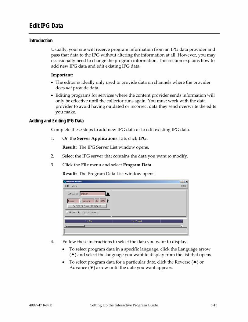
3. Click the File menu and select Program Data.
Result: The Program Data List window opens.
4. Follow these instructions to select the data you want to display. • To select program data in a specific language, click the Language arrow
() and select the language you want to display from the list that opens. • To select program data for a particular date, click the Reverse () or
Advance () arrow until the date you want appears.

5-16 Setting Up the Interactive Program Guide 4009747 Rev B
Edit IPG Data, Continued
5. Click Get Data From Database.
Result: A message appears at the bottom of the Program Data List window letting you know that the DNCS is loading the data you selected.
Note: It may take a few minutes for the program data to load.
6. Complete one of the following tasks:
• To add new program data to the IPG, click the File menu and select New. The Set Up Program Data window opens. Go to step 8.
• To edit existing program data, use the scroll bars along the bottom and right sides of the window to locate the program whose data you want to edit. Then, select the program.
Note: To display only the services that have been placed on a channel map, click to enable Show only mapped services.

4009747 Rev B Setting Up the Interactive Program Guide 5-17
Edit IPG Data, Continued
7. Click the File menu and select Open.
Result: The Set Up Program Data window opens and displays existing data for the program you selected.
8. Complete one of the following tasks: • To add new program data, complete all the fields of the Set Up Program
Data window by typing in the required information. • To modify existing program data, change any of the existing data by
typing in the new data.

5-18 Setting Up the Interactive Program Guide 4009747 Rev B
Edit IPG Data, Continued
9. Click the Features tab.
Result: The Features tab moves to the forefront.
10. Complete one of the following tasks:
• If you are adding new program data, select all the features that apply to the program that you are adding.
• If you are modifying existing program data, select features that apply to the program or clear features that no longer apply.
Important: Not all feature tags listed can be displayed by all versions of SARA. For example, the High Definition feature only displays in SARA 1.52 and later.
11. Click Save.
Result: The Set Up Program Data window closes.
12. Repeat steps 4 to 11 to add or edit other program data.
13. After you have completed adding or editing program data, click the File menu in the IPG Server List window, and select Send.
Result: The IPG Server sends the updated information to the IPG collector.

4009747 Rev B Setting Up the Interactive Program Guide 5-19
Edit IPG Data, Continued
Place Your Company’s Logo on the Main Screen of the IPG
Each time subscribers tune to the IPG, remind them who provides this service by placing your company’s logo on the main screen of the IPG. Adding a file containing your company’s logo to the BFS causes the logo to appear on the main screen of the IPG. You can also use the MSO Logo Position option to position the logo to either the left or right of the channel number.
This section describes how to add a file containing your company’s logo to the BFS and how to position the logo on the main screen of the IPG.
Logo Positions
The following screens show an example of the logo positions.
Logo to the left
Logo to the right
5-20 Setting Up the Interactive Program Guide 4009747 Rev B
Edit IPG Data, Continued
Add a File Containing Your Company’s Logo to the BFS
To add a file containing your company’s logo to the BFS, perform the following steps.
1. Has the cable service provider’s logo been placed on the OSM data carousel? • If yes, go to step 6. • If no, go to step 2.
2. Open an xterm window on the DNCS.
3. Type cd /dvs/resapp/logos and press Enter.
Result: The system makes /dvs/resapp/logos the working directory.
4. Copy the file containing the logo from the directory where it is currently stored to/dvs/resapp/logos.
5. Type exit and press Enter.
Result: The xterm window closes.
6. Click the DNCS tab on the DNCS Administrative Console window.
7. Click the Element Provisioning tab.
8. Select OS in the DHCT Provisioning area.
Result: The DHCT OS List window opens.
9. If there is an entry in the DHCT OS list named msologo.rle, select msologo.rle and delete it by clicking File and choosing Delete. Otherwise, go to step 10.
10. Click File and select New.
Result: The Set Up DHCT OS window opens.
11. Click Browse in the Source File field.
Result: The Select OS File window opens.
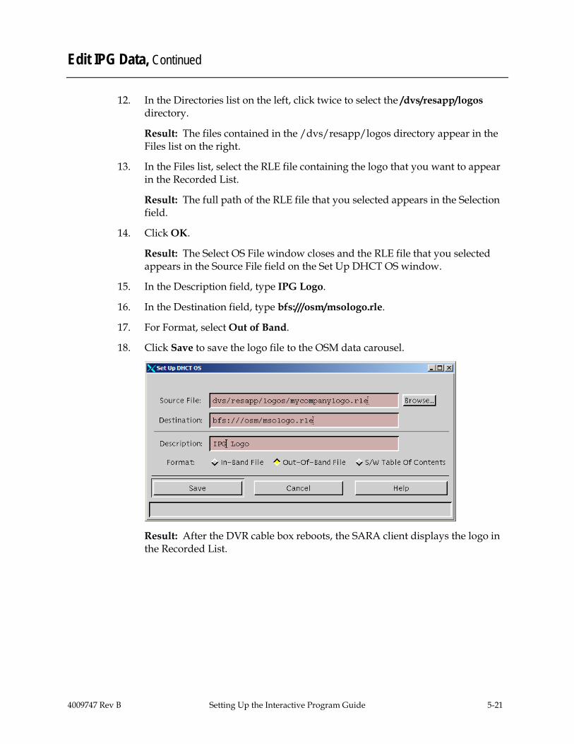
4009747 Rev B Setting Up the Interactive Program Guide 5-21
Edit IPG Data, Continued
12. In the Directories list on the left, click twice to select the /dvs/resapp/logos directory.
Result: The files contained in the /dvs/resapp/logos directory appear in the Files list on the right.
13. In the Files list, select the RLE file containing the logo that you want to appear in the Recorded List.
Result: The full path of the RLE file that you selected appears in the Selection field.
14. Click OK.
Result: The Select OS File window closes and the RLE file that you selected appears in the Source File field on the Set Up DHCT OS window.
15. In the Description field, type IPG Logo.
16. In the Destination field, type bfs:///osm/msologo.rle.
17. For Format, select Out of Band.
18. Click Save to save the logo file to the OSM data carousel.
Result: After the DVR cable box reboots, the SARA client displays the logo in the Recorded List.

5-22 Setting Up the Interactive Program Guide 4009747 Rev B
Edit IPG Data, Continued
Position Your Logo on the Main Screen of the IPG
To position your logo on the main screen of the Interactive Program Guide, perform the following steps.
1. On the DNCS Administrative Console, select the Server Applications tab.
2. Click DHCT Config.
Result: The DHCT Configure Prompt window opens.
3. Select Global. Result: The Set Up Global DHCT Configuration window opens.
4. Select the IPG tab.
Result: The IPG tab appears in the forefront.
5. For the MSO Logo Position option, select either Left or Right to place your logo either to the left or to the right of the channel number on the Interactive Program Guide.
6. Click Save.
Result: The logo appears either to the left or right of the channel number on the Interactive Program Guide.
Configuring SARA to Enhance Your Subscribers’ Experience Explorer DHCTs use a standard set of default parameters that define the way they operate and affect subscribers’ experience with SARA. You can create customized sets of these parameters (called DHCT configurations) and apply different DHCT configurations to all DHCTs in your network, to all DHCTs in a hub, or to a single DHCT.
For assistance configuring SARA, refer to Enhancing Your Subscribers’ Experience.

4009747 Rev B Setting Up a Virtual Channel Service 6-1
Chapter 6 Setting Up a Virtual Channel Service
Overview
Introduction
Virtual channels are channels that display text (using a special limited HTML command set) when a subscriber tunes to them. The file that contains the information must be on the SARA Server. This information may include announcements of civic organizations, community organizations, or local businesses.
Cable service providers use this service to provide a variety of information to subscribers. Virtual channels are typically available to all subscribers. These are not “real” RF channels. They allow the cable operators to create text channels (usually information channels) without using RF spectrum.
The Virtual Channel Server (VCS) interacts with the BFS, SAM, and Channel Map to provide services to the DHCTs that display text information. This section describes how to configure the VCS BFS, how to build or edit a virtual channel source file, and how to set up virtual channels and register them with the SAM and BFS to make the service available to subscribers.
Important: Building and editing a virtual channel source file requires a thorough knowledge of HTML. The instructions provided in this chapter are no substitute for a thorough knowledge of HTML.
In This Chapter
This chapter contains the following topics.
Topic See Page
Configure the VCS Broadcast File System (BFS) 6-2
Build a Virtual Channel Source File 6-6
Set Up a Virtual Channel Service 6-9

6-2 Setting Up a Virtual Channel Service 4009747 Rev B
Configure the VCS Broadcast File System (BFS)
Introduction
Typically during a system upgrade, the installer configures the BFS by adding a virtual channel server to the BFS. However, if this procedure was not performed at the time of upgrade, use the following procedures to check or configure a BFS server for the virtual channel service.
In earlier releases of the SARA Server, virtual channel files could only exist on BFS Source ID 2 (inband) with other OSM files such as PowerTV®
Important Note for Multiple-Site (RCS-Enabled) Systems: Manually setting up any BFS server or source for the SARA Server’s use must be done for the “AllSites” site only, and not for any other individual sites in your system. Otherwise, the server and source will fail.
and SARA ROM. With recent modifications to the arrangement of alternating BFS files, small virtual channel server files now circulate very slowly, and leave the virtual channels practically useless. To resolve this issue, you must move the virtual channel files to a new source. Doing so allows the BFS to update the information it sends to the DHCTs and the virtual channels can then appear faster.
Procedure at a Glance To configure the BFS for the virtual channel server, complete the following tasks.
Note: For detailed instructions on adding a VCS application to the BFS, refer to Adding and Removing Applications on the BFS for SR 2.5/3.5.
1. Create a new digital source with the following characteristics in the Source List window: • Source Name: You can enter any name that helps you to remember the
service this source provides. For example, you might use “VCS BFS Source.”
• Source ID: An unused even number that is greater than 200.
Note: To define these characteristics, display the Set Up Source window by following this quick path: DNCS Administrative Console > DNCS tab > System Provisioning tab > Source > File > New.

4009747 Rev B Setting Up a Virtual Channel Service 6-3
Configure the VCS Broadcast File System (BFS), Continued
2. Create a new source definition with the following characteristics in the Source Definition List window: • Session ID: 00:00:00:00:00:00 plus the number used for the Source ID • Session Definition: BFS
Note: To define these characteristics, display the Set Up Digital Source Definition window, by following this quick path: DNCS Administrative Console > DNCS tab > System Provisioning tab > Source > [Select Source] > File > Source Definitions > File > New Digital.
3. Add a source with the following characteristics to the Sources tab of the BFS Administration window:
Important: Multi-site (RCS-enabled) systems should use the All Sites tool to add a source to the Sources tab on the Site AllSites BFS Administration window. • Source Name: Use the same name that you used for the Source Name in
step 1. • Source ID: Use the same number that you used for the Source ID in step 1. • Source Type: BFS • Transport Type: ASI In-band or In-band • Data Rate: 0.5 Mbps or less
Note: You may also use a value as low as 0.1 Mbps. The maximum rate you can enter for inband data is 2.00 Mbps. For assistance, refer to Recommendations for Data Carousel Rate Management Technical Bulletin.
• Block Size and Indication Interval: Use the default values • Selected Hosts: Select the host according to your system configuration:
− For single-site systems, select dncsatm. − For multiple-site (RCS-enabled) systems, select AllSitesHost.
Note: To define these characteristics, display the Set Up BFS Source window by following the quick path for your system configuration: • Single-Site System: DNCS Administrative Console > Application
Interface Modules tab > BFS Admin > Sources tab > File > New • Multi-Site System: DNCS Administrative Console > Application Interface
Modules tab > BFS Admin > File > All Sites > Sources tab > File > New

6-4 Setting Up a Virtual Channel Service 4009747 Rev B
Configure the VCS Broadcast File System (BFS), Continued
4. Add a server with the following characteristics to the Servers tab in the BFS Administration window:
Important: Multi-site (RCS-enabled) systems should use the All Sites tool to add the server with the following characteristics to the Servers tab in the Site AllSites BFS Administration window. • Server Name: VCS • Selected Sources List: VCS Source
Note: To define these characteristics, display the Authorize BFS Server window by following the quick path for your system configuration: • Single-Site System: DNCS Administrative Console > Application
Interface Modules tab > BFS Admin > Servers tab > File > New • Multi-Site System: DNCS Administrative Console > Application Interface
Modules tab > BFS Admin > File > All Sites > Servers tab > File > New
5. Register the server with the BFS Client by adding a server with the following characteristics to the Broadcast File Server List window: • Server Name: VCS • Mode: One-way • Selected Sources: VCS
Note: To define these characteristics, display the Set Up Server window by following the quick path for your system configuration: • Single-Site Systems: DNCS Administrative Console > Application
Interface Modules tab > BFS Client > File > New Server • Multi-Site Systems: DNCS Administrative Console > Application
Interface Modules tab > BFS Client > File > All Sites > File > New Server
6. Configure the new BFS server source ID on the virtual channel server. For assistance go to Configuring the New BFS Server Source ID, next in this section.

4009747 Rev B Setting Up a Virtual Channel Service 6-5
Configure the VCS Broadcast File System (BFS), Continued
Configuring the New BFS Server Source ID
The final step in configuring the BFS source ID is to configure the new BFS server source ID on the server. Perform the following steps to configure the BFS server source ID.
1. On the DNCS Administrative Console, select the Server Applications tab.
2. Click VCS.
Result: The VCS List window opens.
3. Click the File menu and select Configure. Result: The Configure VCS window opens.
4. Verify that the number that appears in the BFS Server Source ID field matches the BFS server source ID you created earlier, then click OK to return to the VCS List window.
5. Click the File menu and select Close to exit the VCS List window. 6. On the SARA Server, run appControl. 7. In the appControl window, stop and restart the VC server group.
Result: Approximately 1 minute after the server restarts, the BFS sends the updated information to the DHCTs. This update means that the virtual channels take less time to display when a subscriber tunes to the channel.
8. Verify that the virtual channels operate correctly.

6-6 Setting Up a Virtual Channel Service 4009747 Rev B
Build a Virtual Channel Source File
Introduction
When building a virtual channel source file, you must first complete the following tasks.
1. Create the source HTML files for the virtual channel client to use.
2. Save the source HTML files to the appropriate directory on the SARA Server.
Although this section provides procedures for building a source file for a virtual channel, a thorough knowledge of HTML is required to perform these procedures successfully. The instructions provided in this section are no substitute for a thorough knowledge of HTML.
Creating the Source HTML Files These files provide the content for a virtual channel in the same way that a local studio or satellite feed provides content for a clear broadcast. Therefore, by creating the HTML file, you create a source for the virtual channel service.
You can use any HTML editor to create a document that contains the information you want the subscriber to see. However, when formatting the text you can only use the tags in the following table.
Important: The behavior of the Virtual Channel client is unpredictable if you use any tags that do not appear in the following table to create an HTML document. Only these tags are supported because the SARA client uses the Virtual Channel application (not a standard, full-featured browser) to read the source file.
Tag Meaning
<b></b> Display text between tags as bold text
<big></big> Display text between tags as large text
<br> Insert blank rule (line break)
<br1.5> Insert 1.5 blank rules (1.5 line break)
<center></center> Display text and images between tags as horizontally centered on the line
<img scr="ok.img"> Display the SELECT button.
<img scr="a.img"> Display the A button.
<img scr="b.img"> Display the B button.
<img scr="c.img"> Display the C button

4009747 Rev B Setting Up a Virtual Channel Service 6-7
Build a Virtual Channel Source File, Continued
Tag Meaning
<img scr="settings.img"> Display the SETTINGS button.
<font color="white"> Change the font color to white.
<font color="black"> Change the font color to black.
<font color="yellow"> Change the font color to yellow.
<table bgcolor="alert"></table> Applies a standard 3-row alert-banner background to the table.
<table bgcolor="swirl"></table> Applies a purple swirl graphic to the background of the table.
<table bgcolor="none"></table> Applies a transparent background to the table.
<tr> Define a table row. (For alert banner background, there must be at least three rows per table.)
Example: The following is a sample HTML document with the recommended tags for a Virtual Channel client.
6-8 Setting Up a Virtual Channel Service 4009747 Rev B
Build a Virtual Channel Source File, Continued
Saving the Source HTML Files
After creating the source HTML files using the appropriate tags, you must save the files in the /dvs/appFiles/html directory on the DNCS. Use the parse utility in the /dvs/appserv/bin directory to verify that the Virtual Channel client can display your files.
Perform the following steps to run the parse utility.
1. Create two directories.
2. Name one good and the other bad.
3. Save them in the /dvs/appFiles/html directory.
Result: The following three directories appear for HTML files: • /dvs/appFiles/html • /dvs/appFiles/html/good • /dvs/appFiles/html/bad
4. In an xterm window, type parse <filename> to run the parse utility.
Note: Replace the <filename> in this entry with the name of the HTML file that you created.
Result:
One of the following results occurs: • If the Virtual Channel can use your HTML file, the parse utility displays
the following: Parsed file <file.html>, no errors found. Moved the file to <good/file.html>.
• If the Virtual Channel cannot use your HTML file, the parse utility displays the following: Parsed file <file.html>, errors found. Moved the file to <bad/file.html>. Please look at <bad/file.err> for details
Note: File.err lists line numbers of any lines of text that use HTML tags not recognized by the Virtual Channel client.

4009747 Rev B Setting Up a Virtual Channel Service 6-9
Set Up a Virtual Channel Service
Introduction When setting up a virtual channel service, you must first complete the following tasks.
1. Set up the virtual channel service.
2. Place the virtual channel service on the Channel Map.
This section provides procedures for completing these tasks, as well as for modifying a virtual channel configuration, editing a source file, and deleting a virtual channel.
Setting Up the Virtual Channel Service Now that you have created your source HTML file and saved it on your DNCS for your virtual channels, you are ready to set up your virtual channel service.
Use the following steps to set up virtual channels.
1. On the DNCS Administrative Console, click the Server Applications tab.
2. Click VCS.
Result: The VCS List window opens.
3. Click the File menu and select New.
Result: The Set Up VCS window opens.
4. Type the service name, short description, and long description in their
respective fields.

6-10 Setting Up a Virtual Channel Service 4009747 Rev B
Set Up a Virtual Channel Service, Continued
5. In the Data File field, click Select.
Result: The Source URL Selection window opens.
Note: As part of setting up the virtual channel service, you must define the source that the service uses by linking the new service with an HTML file that you created earlier.
6. Browse to the directory and select the HTML file to display on the virtual channel.
Note: The recommended place to save the html files is in /dvs/appFiles/html/good or in one of its subdirectories.
7. Click OK to return to the Set Up VCS window.
8. Type the logo index in the Logo Index field.
9. Click Save.
Placing the Virtual Channel on the Channel Map After you set up a virtual channel service, you must place the virtual channel on a channel map. Refer to the Digital Network Control System Online Help (UNIX) Version for your system release.

4009747 Rev B Setting Up a Virtual Channel Service 6-11
Set Up a Virtual Channel Service, Continued
Modifying a Virtual Channel Configuration
Use the following steps to modify a virtual channel configuration.
1. On the VCS List window, select the row of the desired service.
2. Click the File menu and select Open.
3. Make desired changes on the Set Up VCS window, and click Save.
Editing a Source File The source files for virtual channels are links. As a result of editing, the source automatically forces the channel to update on the DHCTs.
Use the following steps to edit a source file.
1. Open the source file in the editor and make the changes you require.
2. Use the parse utility to verify your changes.
3. Check for updated information.
Deleting a Virtual Channel Use the following steps to delete a virtual channel.
1. Select the virtual channel you want to delete in the VCS List window.
2. Click the File menu and select Delete.
Result: A Question window opens, prompting you to confirm that you want to delete the current item.
3. Click Yes to confirm that you want to delete the virtual channel.

4009747 Rev B Enabling Tracing on the SARA Server 7-1
Chapter 7 Enabling Tracing on the SARA Server
Overview
Introduction
The SARA Server can track the flow of data messages between the SARA Server and other network elements and store those messages in a log file. The process of tracking those data messages is called tracing.
This chapter provides procedures to enable and disable the tracing function and to specify the level of detail that you want to include in the log file.
In This Chapter
This chapter contains the following topics.
Topic See Page
Enable Tracing 7-2
View the Log Files 7-6

7-2 Enabling Tracing on the SARA Server 4009747 Rev B
Enable Tracing
Introduction The SARA Server includes a tracing function, which tracks the flow of information through SARA Server processes. In order to capture this information to a log file, you must enable tracing on the SARA Server. Important: Cisco Services may request that you enable tracing so you can capture this information for diagnostic purposes.
Understanding Trace Levels You can choose to trace varying information with varying degrees of detail. You do this through the use of trace levels. Trace levels let you specify how much information you want to include in the log file. The following table provides valid trace levels:
Trace Level Definition 0 Reports only errors. This level is always turned on by default
whenever tracing is enabled. 1 Reports errors and debug information. 2 Reports errors, debug information, and flow information.
The trace.cfg File The SARA Server contains a file called/dvs/appserv/tmp/trace.cfg. This file contains commands that let you specify the following options: • Whether to enable or disable tracing for a specific process • The amount of detail that you want to capture to a log file In order to enable or disable tracing or to change the trace levels for a process, you must edit the trace.cfg file. After you make changes to the trace.cfg file, you can run the /dvs/appserv/bin/tools/showTracing utility to put the changes into effect. If you do not run the showTracing utility, any changes that you made to the trace.cfg file may not take effect immediately. It is not necessary to restart any SARA Server processes for changes to take effect.
Viewing Tracing Options Complete these steps to view the tracing options contained in the trace.cfg file. 1. In an xterm window on the SARA Server, type more trace.cfg and press
Enter. Result: A list of tracing options displays on the screen.
2. Examine the list of tracing options to determine which functions you want to enable.
3. Type the Ctrl and C keys simultaneously to exit the more utility. 4. Go to Syntax For the trace.cfg File, next in this section.

4009747 Rev B Enabling Tracing on the SARA Server 7-3
Enable Tracing, Continued
Syntax For the trace.cfg File
You must enter the trace.cfg entries using the following syntax:
tracename programcontext tracelevel
The following table explains each component of the trace.cfg entry. Use the components to build entries for the trace.cfg file.
Part Description
tracename Identifies the subset of code within an executable file that you want to trace. The tracename component can be the trace name that was registered in the executable code, or it can be the library file name without the lib and .* extensions.
The tracename component is optional. You can include tracename to turn on tracing for a given subset of code, such as a library. If it is omitted, tracing is turned on in all contexts for the tracename.
programcontext Identifies the process that you want to trace. The programcontext component can be the name of the executable file or the trace name that was registered in the executable code.
tracelevel Identifies the level of detail that you want to capture for this process.
Examples:
_ipgui 2 The programcontext is _ipgui, and the tracelevel is 2. This entry starts a level 2 trace on the _ipgui process.
gui _ipgui 1 The tracename is gui, the programcontext is _ipgui, and the tracelevel is 1. This entry starts a level 1 trace on code labeled gui in the _ipgui process. (This code may be in the gui library)
All _ipgui 1 The tracename is all, the programcontext is _ipgui, and the tracelevel is 1. This entry starts a level 1 trace on all code in the _ipgui process.
Important: To enable the tracing function, go to Enabling the Tracing Function, next in this section.
7-4 Enabling Tracing on the SARA Server 4009747 Rev B
Enable Tracing, Continued
Enabling the Tracing Function
In order to enable or disable tracing for an SARA Server process, you must edit the /dvs/appserv/tmp/trace.cfg file. Each line in this file represents a trace command for an SARA Server process.
Lines that begin with a pound sign (#) are comments. The tracing function ignores these lines. Therefore, in order to disable tracing, you can simply add a pound sign to the beginning of the corresponding line.
Also, some of these comment lines may contain trace commands that have been disabled. To enable tracing, you can simply remove the pound sign from the beginning of those lines.
Follow these steps to enable the tracing function for an SARA Server process:
1. In an xterm window on the SARA Server, type cd /dvs/appserv/tmp and press Enter.
Result: The /dvs/appserv/tmp directory becomes the working directory.
2. Type vi trace.cfg and press Enter.
Result: The trace.cfg file opens.
3. Does the file contain any comment lines that correspond with the tracing function you want to enable? • If yes, remove the # from the beginning of that line and go to step 5. • If no, go to step 4.
4. Use the arrow keys to scroll to the bottom of the file and add the appropriate entry for the tracing function you want to enable. See The trace.cfg File earlier in this section for more information on writing trace.cfg entries.
5. Type :wq to save and close the file.
6. Type dvs/appserv/bin/tools/showTracing to put the changes into effect.
Important: If you do not perform this step, the changes that you made will not be put into effect.

4009747 Rev B Enabling Tracing on the SARA Server 7-5
Enable Tracing, Continued
Disabling the Tracing Function
Follow these steps to disable the tracing function for an SARA Server process:
1. In an xterm window on the SARA Server, type cd /dvs/appserv/tmp and press Enter.
Result: The /dvs/appserv/tmp directory becomes the working directory.
2. Type vi trace.cfg and press Enter.
Result: The trace.cfg file opens.
3. Find the entry that corresponds with the tracing function you want to disable.
4. Place the cursor at the beginning of the line you want to disable and type #.
Note: It is a good idea to comment out the entry instead of deleting it. By doing so, you can easily enable the command later if necessary. To comment out an entry, add a # to the beginning of the line containing the entry.
5. Type :wq to save and close the file.
6. Type dvs/appserv/bin/tools/showTracing to put the changes into effect.
7-6 Enabling Tracing on the SARA Server 4009747 Rev B
View the Log Files
Introduction
The SARA Server captures various kinds of trace information to various log files. Those log files are stored in two directories: /var/log/dncsLog and /dvs/appserv/tmp. • The files in /var/log/dncsLog only contain error message and process start/stop
messages. The SARA Server automatically deletes these log files after three days. • The files in /dvs/appserv/tmp contain all of the process output that is captured.
The SARA Server automatically deletes these log files after seven days.
The Logger Utility
The SARA Server includes a utility called Logger that manages the size, name, and placement of the log files in the/dvs/appserv/tmp directory. Logger stores these files for seven days. Logger creates a new log file for each traced process every day or when the previous log file reaches a pre-determined size. When Logger creates a new log file, it closes the old file and compresses it using the gzip utility. A compressed file is renamed to include a .gz extension.
Viewing the Log File To view the data in a zipped log file, type gzip –dc <filename>.gz and press Enter. In this command, <filename> is the name of the file you want to view. When you enter this command, the SARA Server creates an unzipped file without the .gz extension.
For example, to view the data in vcServer.101.gz, type gzip –dc vcServer.101.gz and press Enter. The SARA Server creates an unzipped file called vcServer.101.

4009747 Rev B Enabling Tracing on the SARA Server 7-7
View the Log Files, Continued
Log File Naming Conventions
Log files for individual processes are stored in the /dvs/appserv/tmp directory. These files are named after the process that they traced, and the filename contains a three-character extension. For example, ppvfileserver.201 contains trace information for the ppvfileserver process.
The first character of the three-character extension identifies the day of the week that the information was captured:
Character Day of the Week
0 Sunday
1 Monday
2 Tuesday
3 Wednesday
4 Thursday
5 Friday
6 Saturday
The second and third characters number the files that were created for a specific process during a specific day, beginning with 00 and going through 99.
Examples: • The vcServer.400 file contains the first section of trace information for last
Thursday for the vcServer process. • The bfsRemote.003 file contains the fourth section of trace information for last
Sunday for the bfsRemote process.
If any processes are running multiple instances, such as the ipgServer, the log files will be named after the programContext instead the programName. For example, ipgServer-eng.201 contains the second section of trace information for last Tuesday for the ipgServer-eng process.

4009747 Rev B Adding a dvd Server to the BFS and Updating the dvd Server With New Files 8-1
Chapter 8 Adding a dvd Server to the BFS and
Updating the dvd Server With New Files Overview
Introduction
This chapter provides procedures for adding a dvd server to the BFS and updating the dvd server with DVD files. These files enable SARA server software to support the DVD copying (burning) feature of Explorer set-top boxes that offer this feature.
During a system upgrade, the installer may have configured the BFS for a dvd server and added DVD files to the server. However, if this procedure was not performed at the time of the upgrade, use the information in this chapter to add a BFS dvd server and to add files to the dvd server for the first time. Also use the information in this chapter to update a dvd server with new files when necessary.
Starting with SR 2.5/3.5/4.0 and later, a dvd server has been added to the BFS to support the DVD burning capability of SARA Server software. This capability is required to fully support Explorer set-top boxes that have the ability to burn content from the hard drive of the set-top box to the DVD drive.
Important: The instructions in this chapter provide data required to add a dvd server to the BFS. For step-by-step instructions on adding a server to the BFS, refer to Adding and Removing Applications on the BFS for SR 2.5/3.5.
In This Chapter
This chapter contains the following topics.
Topic See Page
Add a DVD Server to the BFS 8-2
Update a DVD Server 8-4
8-2 Adding a dvd Server to the BFS and Updating the dvd Server With New Files 4009747 Rev B
Add a DVD Server to the BFS
Introduction
This section describes how to add a BFS dvd server to your system. A BFS dvd server is required to fully support the DVD burning capability of DVR-DVD set-top boxes.
Important Note for Multiple-Site (RCS-Enabled) Systems: Setting up any BFS server or source for the SARA Server’s use must be done for the “AllSites” site only, and not for any other individual sites in your system. Otherwise, the server and source will fail.
Adding a dvd Server to the BFS Follow these procedures to add a dvd server to the BFS. If your system uses the Regional Control System (RCS) option and supports multiple sites, add a dvd server to only the AllSites BFS and not to the BFS of individual sites.
Note: For step-by-step instructions on adding a server to the BFS, refer to Adding and Removing Applications on the BFS for SR 2.5/3.5.
1. Add a server with the following characteristics to the Servers tab of the BFS Administration window: • Server Name: dvd
Important: This field requires a specific entry. You must enter “dvd” in lowercase letters in this field. Otherwise, the system will be unable to set up a dvd server.
• Selected Sources: Inband and Out of Band
Important: Multi-site (RCS-enabled) systems must add the dvd server to only the Site AllSites Administration window. Adding a dvd server to the BFS Administration window of individual sites and to the Site AllSites Administration window causes the dvd server to fail.
Note: To define these characteristics, display the Authorize BFS Server window by following the quick path for your system configuration: • Single-Site Systems: DNCS Administrative Console > Application
Interface Modules tab > BFS Admin > Servers tab > File > New • Multi-site Systems: DNCS Administrative Console > Application
Interface Modules tab > BFS Admin > File > All Sites > Servers tab > File > New
4009747 Rev B Adding a dvd Server to the BFS and Updating the dvd Server With New Files 8-3
Add a DVD Server to the BFS, Continued
2. Register the server with the BFS Client by adding a server with the following characteristics to the Broadcast File Server List window: • Server Name: dvd • Mode: One-way • Selected Sources: Out of Band
Important: Multi-site (RCS-enabled) systems must add the dvd server to only the All Sites Broadcast File Server List window. Adding a dvd server to the Broadcast File Server window of other individual sites and to the All Sites Broadcast File Server List window prevents the system from setting up a dvd server.
Note: To define these characteristics, display the Set Up Server window by following the quick path for your system configuration: • Single-Site systems: DNCS Administrative Console > Application
Interface Modules tab > BFS Client > File > New Server • Multi-Site systems: DNCS Administrative Console > Application
Interface Modules tab > BFS Client > File > All Sites > File > New Server
3. Add DVD files to the dvd server in the BFS Client window. For assistance, go to Update a DVD Server With New Files, next in this chapter.
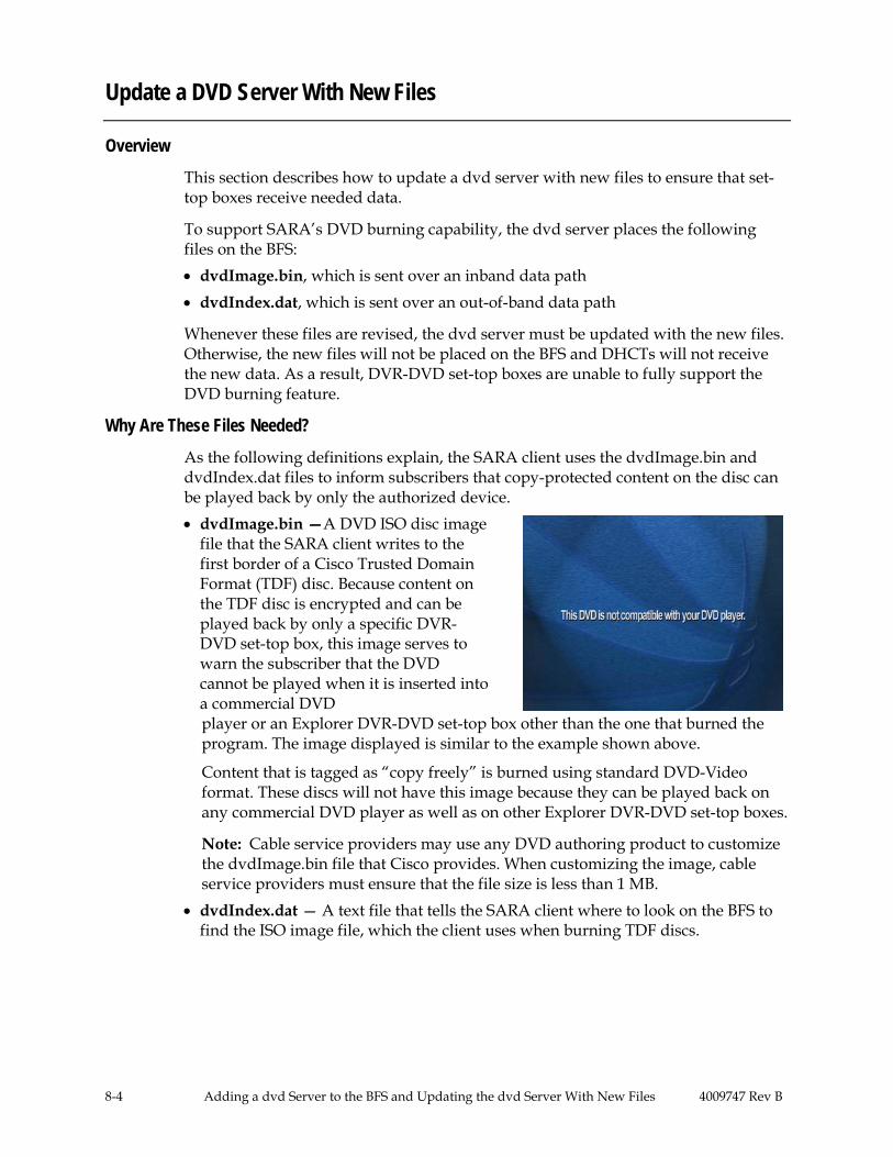
8-4 Adding a dvd Server to the BFS and Updating the dvd Server With New Files 4009747 Rev B
Update a DVD Server With New Files
Overview
This section describes how to update a dvd server with new files to ensure that set-top boxes receive needed data.
To support SARA’s DVD burning capability, the dvd server places the following files on the BFS: • dvdImage.bin, which is sent over an inband data path • dvdIndex.dat, which is sent over an out-of-band data path
Whenever these files are revised, the dvd server must be updated with the new files. Otherwise, the new files will not be placed on the BFS and DHCTs will not receive the new data. As a result, DVR-DVD set-top boxes are unable to fully support the DVD burning feature.
Why Are These Files Needed?
As the following definitions explain, the SARA client uses the dvdImage.bin and dvdIndex.dat files to inform subscribers that copy-protected content on the disc can be played back by only the authorized device. • dvdImage.bin —A DVD ISO disc image
file that the SARA client writes to the first border of a Cisco Trusted Domain Format (TDF) disc. Because content on the TDF disc is encrypted and can be played back by only a specific DVR-DVD set-top box, this image serves to warn the subscriber that the DVD cannot be played when it is inserted into a commercial DVD player or an Explorer DVR-DVD set-top box other than the one that burned the program. The image displayed is similar to the example shown above.
Content that is tagged as “copy freely” is burned using standard DVD-Video format. These discs will not have this image because they can be played back on any commercial DVD player as well as on other Explorer DVR-DVD set-top boxes.
Note: Cable service providers may use any DVD authoring product to customize the dvdImage.bin file that Cisco provides. When customizing the image, cable service providers must ensure that the file size is less than 1 MB.
• dvdIndex.dat — A text file that tells the SARA client where to look on the BFS to find the ISO image file, which the client uses when burning TDF discs.

4009747 Rev B Adding a dvd Server to the BFS and Updating the dvd Server With New Files 8-5
Update a DVD Server With New Files, Continued
Updating the DVD Server
Follow these instructions to place DVD files on a newly created dvd server or to update an existing dvd server with new DVD files.
Note: Update a dvd server with DVD files immediately after adding a dvd server to the BFS and from that point on, whenever DVD files are changed or updated.
1. From the DNCS Administrative Console, click the Server Applications tab.
Result: The Server Applications tab moves to the forefront.
2. Click DVD.
Result: The DVD V-IMAGE window opens as shown in the following example.
Shows the size of the file that was most recently uploaded.
Shows the time and date that the most recent upload occurred. Shows where the image file is stored on
the BFS.
Shows the version of the file that was most recently uploaded.
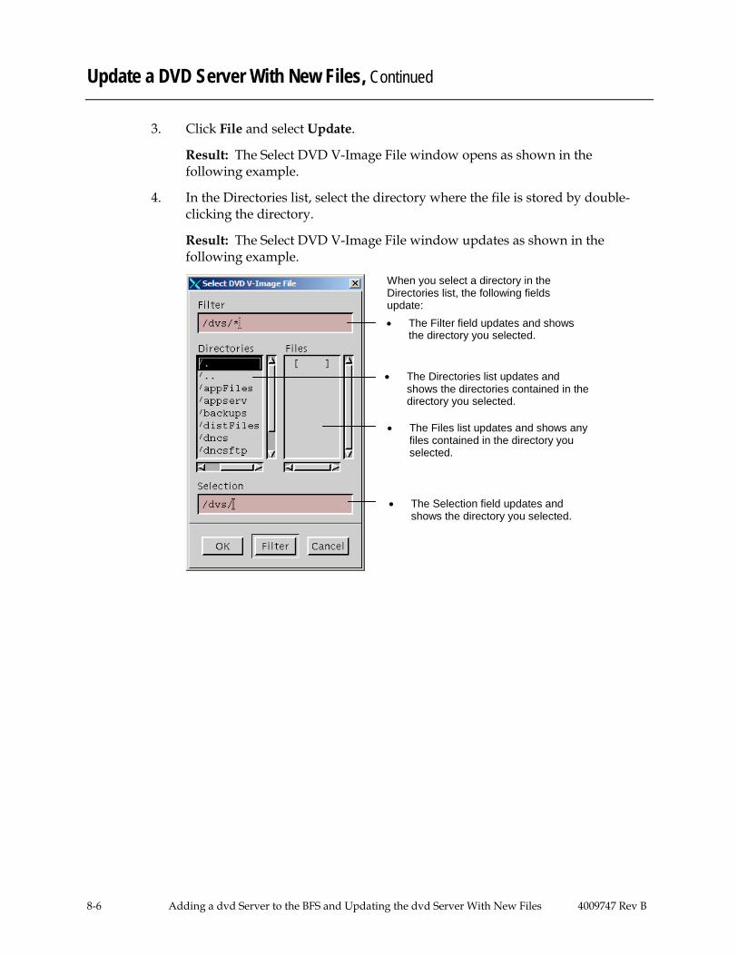
8-6 Adding a dvd Server to the BFS and Updating the dvd Server With New Files 4009747 Rev B
Update a DVD Server With New Files, Continued
3. Click File and select Update.
Result: The Select DVD V-Image File window opens as shown in the following example.
4. In the Directories list, select the directory where the file is stored by double-clicking the directory.
Result: The Select DVD V-Image File window updates as shown in the following example.
When you select a directory in the Directories list, the following fields update:
• The Selection field updates and shows the directory you selected.
• The Filter field updates and shows the directory you selected.
• The Directories list updates and shows the directories contained in the directory you selected.
• The Files list updates and shows any files contained in the directory you selected.

4009747 Rev B Adding a dvd Server to the BFS and Updating the dvd Server With New Files 8-7
Update a DVD Server With New Files, Continued
5. Continue selecting directories in the Directories list until the file you want to update (dvdImage.bin or dvdIndex.dat) appears in the Files list.
6. When the source file you want to use appears in the Files list, double-click the file in the Files list.
Result: The Select DVD V-Image File window updates and shows the full path of the file you selected, as shown in the following example.
When you double-click a file in the Files list, the Selection field updates and shows the full path of the file.

8-8 Adding a dvd Server to the BFS and Updating the dvd Server With New Files 4009747 Rev B
Update a DVD Server With New Files, Continued
7. Click OK to upload this file to the dvd server.
Result: The Select DVD V-Image File window closes and the DVD V-IMAGE window updates as shown in the following example.
Tip: The File Length field provides extra assurance that a new file was placed on the BFS. Generally a change in the size of the file indicates that the new file was placed on the BFS. On the other hand, no change in the size of the file may indicate that the dvd server uploaded the BFS with the existing file.
8. Does the Status field show Update succeeded?
• If yes, go to step 9. • If no, contact Cisco Services for assistance.
9. Do you need to upload another DVD V-Image file to the dvd server? • If yes, repeat steps 3 to 8 to upload the other file. • If no, you have successfully updated all dvd servers in your system. To
close the DVD V-IMAGE window, click File and select Close.
When the file is completely uploaded to the dvd server, the Status field indicates that the upload was successful.
When you update the DVD server with a new DVD-V Image file, these fields update and show information about the new file.

4009747 Rev B Customer Information 9-1
Chapter 9 Customer Information
If You Have Questions
If you have technical questions, call Cisco Services for assistance. Follow the menu options to speak with a service engineer.
Access your company's extranet site to view or order additional technical publications. For accessing instructions, contact the representative who handles your account. Check your extranet site often as the information is updated frequently.In This Chapter

4009747 Rev B Glossary-1
Glossary
App Server See Application Server.
Application Server Application Server. A computer workstation and server used to execute the application programs, which provide an interface for downloading application data to the DHCTs. App Server works in conjunction with the DNCS and the two computers share a common database. See also SARA Server.
ASI Asynchronous Serial Interface.
ATM Asynchronous Transfer Mode. A network protocol designed to handle all aspects of multimedia: video, audio, and data.
ATM Switch A device that receives digital data from the DNCS and AppServer using two separate PVCs. The switch uses classical IP over ATM to send digital data to a router on the forward data channel.
BFS Broadcast File System. Primary interface (means of communication) between the App Server and the DHCTs that are connected to the network.
BFS BIG A device that processes the data it receives and sends it to the data QAM modulator.
BIG Broadband Integrated Gateway. A device that provides a data pipeline from the DNCS to the DHCTs.
Brick mode A state in which a DHCT displays no video or audio and the front panel LED only displays four dashes (“- - - -“). This state is controlled through the use of a brick mode avoidance package. If the DHCT is not authorized for this package, then the DHCT enters brick mode. Brick mode is sometimes called “Allow Service Disconnect.”
Burn To write data from the hard drive of the cable box to the DVD drive.
CA conditional access. Consists of the system, software, and components necessary to provide for selective access or denial of specific services in a network. Establishes means by which a cable service provider can collect subscriptions or other payments for services received.
CableCARD See POD module.
CAM Conditional Access Manager. Network encryption control, entitlement definition and management, and authorization control (see PowerKEY).
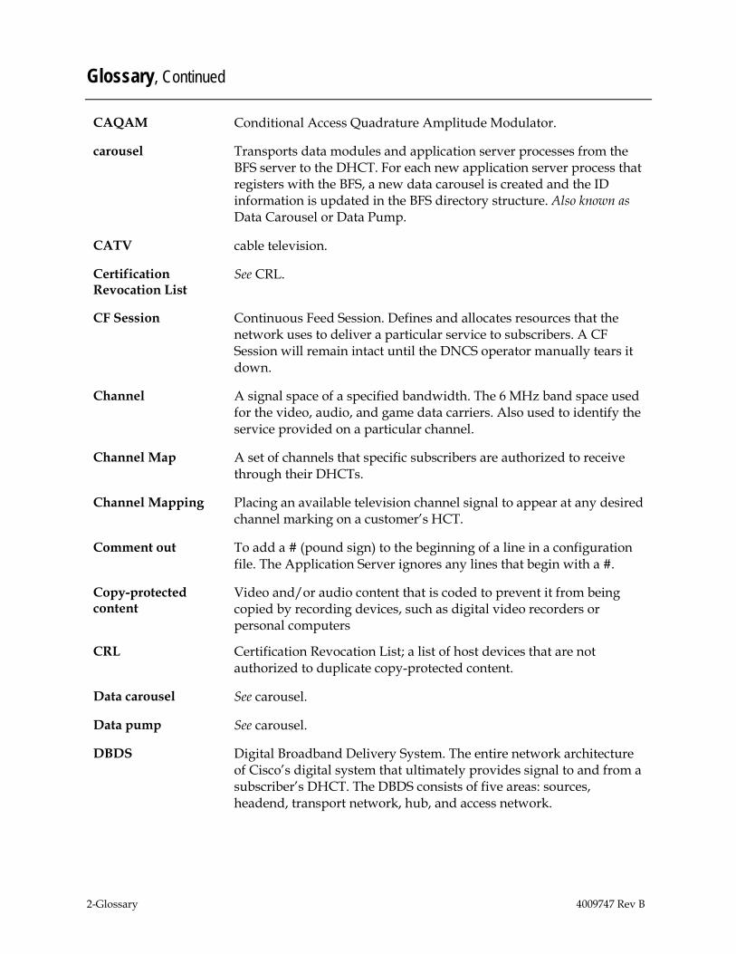
2-Glossary 4009747 Rev B
Glossary, Continued
CAQAM Conditional Access Quadrature Amplitude Modulator.
carousel Transports data modules and application server processes from the BFS server to the DHCT. For each new application server process that registers with the BFS, a new data carousel is created and the ID information is updated in the BFS directory structure. Also known as Data Carousel or Data Pump.
CATV cable television.
Certification Revocation List
See CRL.
CF Session Continuous Feed Session. Defines and allocates resources that the network uses to deliver a particular service to subscribers. A CF Session will remain intact until the DNCS operator manually tears it down.
Channel A signal space of a specified bandwidth. The 6 MHz band space used for the video, audio, and game data carriers. Also used to identify the service provided on a particular channel.
Channel Map A set of channels that specific subscribers are authorized to receive through their DHCTs.
Channel Mapping Placing an available television channel signal to appear at any desired channel marking on a customer’s HCT.
Comment out To add a # (pound sign) to the beginning of a line in a configuration file. The Application Server ignores any lines that begin with a #.
Video and/or audio content that is coded to prevent it from being copied by recording devices, such as digital video recorders or personal computers
Copy-protected content
CRL Certification Revocation List; a list of host devices that are not authorized to duplicate copy-protected content.
Data carousel See carousel.
Data pump See carousel.
DBDS Digital Broadband Delivery System. The entire network architecture of Cisco’s digital system that ultimately provides signal to and from a subscriber’s DHCT. The DBDS consists of five areas: sources, headend, transport network, hub, and access network.

4009747 Rev B Glossary-3
Glossary, Continued
Demodulator Receives information such as billing and performance monitoring data in a reverse path from the DHCT and returns it to the DNCS for processing.
DHCT Digital Home Communications Terminal. Cisco’s digital set-top converter that is two-way capable for interactive services. See also Explorer.
DNCS Digital Network Control System. A computer server used to monitor and control the DBDS network elements. Generally located at the DBDS headend, although it may be located elsewhere and remotely connected to the DBDS.
ECM Entitlement Control Message. System-wide information that “unlocks” an encrypted service by transmitting control words. Each ECM is unique for each service, enables cryptographic partitioning so that different Eas can selectively grant access to their own services.
Element Refers to DBDS devices, groups of devices, and software components that must be “provisioned” from the DNCS. Also known as system components.
Explorer Cisco’s trademarked name for the Digital Home Communications Terminal. Also known in the CATV industry as a set-top box.
®
FAT channel Forward Application Transport channel. Carries programming information (content data) using MPEG-2 transport streams modulated onto RF signals. These channels transmit data at a fast rate (at least 27 Mbps), and therefore require large amounts of bandwidth; 54 MHz to 860 MHz of the broadband spectrum may be reserved for FAT channels.
FTP File Transfer Protocol. Ability to download files from or upload files to remote computer systems on a network, such as Internet.
GQAM gigabit quadrature amplitude modulation.
Headend A headend is the location of the network elements that processes the signal by receiving and preparing the source signals and making them ready for the transport network. See also network elements.
HFC hybrid fiber coax. Consists of fiber optic transmission systems extending from a hub to HFC nodes, and a coax bus network extending from the HFC nodes to the DHCTs within the subscriber’s home.

4-Glossary 4009747 Rev B
Glossary, Continued
Hub Physical locations designed to serve a specific number of subscribers, usually 50 to 15,000. May be collocated with the headend or miles away from the headend. Hubs receive, modulate, and boost the signal prior to sending it to the network of HFC nodes for distribution to the subscriber. Hubs usually contain QPSK modulators/ demodulators that establish the two-way communications with the DHCTs.
Interstitial Programming that appears on PPV channels between events, such as general programming or an advertisement.
IPG Interactive Program Guide. Cisco’s name for the on-screen program guide provided by the Explorer DHCT.
IPPV impulse pay-per-view. Service for which cable subscribers can electronically order program events using two-way (or reverse path) methods. Subscribers are charged a user fee for individual program events. See also PPV.
IPPV Event A segment offered as an IPPV package; a boxing match could be an event offered as an IPPV packet. One IPPV event=one IPPV package.
IPPV Package A package created to contain only one IPPV event and offered to subscribers.
LED light-emitting diode. Semiconductor device that converts electrical energy into light.
A utility on the Application Server that manages the size, name, and placement of the log files in the /dvs/appserv/tmp directory.
Logger
MAC address Media Access Control address. Unique physical address embedded into a network device. Similar to a serial number.
MIB Management Information Base (SNMP data structure).
Modulator Sends control and authorization information from the DNCS to the DHCT.
MPEG Moving Picture Experts Group. An international video compression standards-setting group working under the supervision of the International Standards Organization (ISO) and the International Electrotechnical Commission (IEC). MPEG’s mission is to develop standards for compressed full-motion video, still image, audio and other associated information.

4009747 Rev B Glossary-5
Glossary, Continued
MPEG-2 International video compression standard supporting the interlaced video format used by the TV industry and allowing a scaling of image quality and transmission bandwidth.
MSO multiple system operator. A cable company that operates more than one cable system.
Narrowcast Narrowcast is a term that describes a cable TV signal that is available to only a subset of the subscriber base. Narrowcasting allows cable operators to reuse the same frequency for different content. Narrowcasting is accomplished by placing QAM modulators in the plant closest to the subscribers’ homes. For example, operators can offer popular cable TV shows, such as Animal Planet and HGTV, on frequency A in one part of the plant, and offer local programming on the same frequency in another part of the plant.
Network elements Devices typically located at the headend, which include satellite receivers (IRT, IRD), Real-Time Encoder (RTE), BIG, QAM modulator, DNCS, and AppServer. Also known as system components. See element.
On-demand session Tangible service, such a movies, that the on-demand network delivers to the subscriber. As the on-demand network matures, the on-demand sessions or MPEG programs routed through the network will broaden to offer services such as music, video teleconferencing, Internet information, and time-shifted TV, including HDTV.
PIN personal identification number.
POD module Point-of-Deployment module; approximately the size of a credit card and inserts into a host device (either a DHCT or cable-ready television) to provide conditional access to secure digital content.
PowerKEY® Cisco’s trademarked name for the hardware and software encryption and decryption of digital signal. Uses secret key, public key, and private key.
Conditional Access system
PowerTV PowerTV’s trademarked name for their operating system software and integrated circuits created for high-speed processing and presentation of interactive graphics and audio for the DHCT.
®
PPV pay-per-view. Service for which cable subscribers are charged a user fee for individual program events. See also IPPV.
PPV barker A screen that the DHCT displays to advertise an event or let a subscriber order a PPV event.
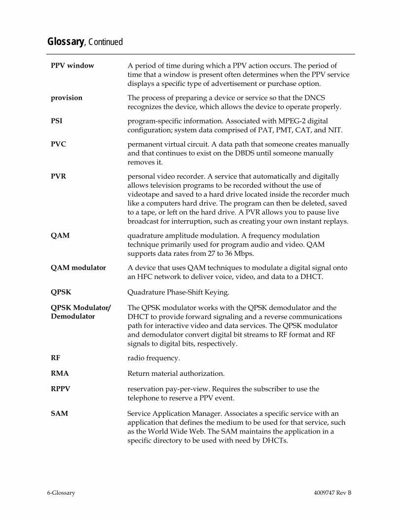
6-Glossary 4009747 Rev B
Glossary, Continued
PPV window A period of time during which a PPV action occurs. The period of time that a window is present often determines when the PPV service displays a specific type of advertisement or purchase option.
provision The process of preparing a device or service so that the DNCS recognizes the device, which allows the device to operate properly.
PSI program-specific information. Associated with MPEG-2 digital configuration; system data comprised of PAT, PMT, CAT, and NIT.
PVC permanent virtual circuit. A data path that someone creates manually and that continues to exist on the DBDS until someone manually removes it.
PVR personal video recorder. A service that automatically and digitally allows television programs to be recorded without the use of videotape and saved to a hard drive located inside the recorder much like a computers hard drive. The program can then be deleted, saved to a tape, or left on the hard drive. A PVR allows you to pause live broadcast for interruption, such as creating your own instant replays.
QAM quadrature amplitude modulation. A frequency modulation technique primarily used for program audio and video. QAM supports data rates from 27 to 36 Mbps.
QAM modulator A device that uses QAM techniques to modulate a digital signal onto an HFC network to deliver voice, video, and data to a DHCT.
QPSK Quadrature Phase-Shift Keying.
QPSK Modulator/ Demodulator
The QPSK modulator works with the QPSK demodulator and the DHCT to provide forward signaling and a reverse communications path for interactive video and data services. The QPSK modulator and demodulator convert digital bit streams to RF format and RF signals to digital bits, respectively.
RF radio frequency.
RMA Return material authorization.
RPPV reservation pay-per-view. Requires the subscriber to use the telephone to reserve a PPV event.
SAM Service Application Manager. Associates a specific service with an application that defines the medium to be used for that service, such as the World Wide Web. The SAM maintains the application in a specific directory to be used with need by DHCTs.

4009747 Rev B Glossary-7
Glossary, Continued
SAP second audio program. A feature that allows cable service providers to offer subscribers a second language option for their programming.
SARA Cisco Resident Application. The set of operating programs that is “permanently” loaded into the DHCT. These applications are immediately available to the subscriber upon activation of the DHCT.
SARA Server Cisco Resident Application (SARA) Server. A computer workstation and server used to execute Cisco’s application programs. These programs provide an interface for downloading application data to DHCTs. The SARA Server works in conjunction with the DNCS and the two computers share a common database.
Service gateway Front-end gateway for the delivery of service through the DBDS. Provides DSM-CC signaling as required to establish network resource for service delivery.
Service group A QAM modulator (or a cluster of QAMs) that is installed for delivering on-demand services to an associated population of DHCTs. The association of a DHCT to a specific service group is determined by first identifying the QAM modulator (or a cluster of QAMs) that a DHCT can receive.
Session See CF session.
shared key authentication
A type of authentication that assumes each station has received a secret shared key through a secure channel independent from an 802.11 network. Stations authenticate through shared knowledge of the secret key. Use of Shared Key authentication requires implementation of the 802.11 Wireless Equivalent Privacy algorithm.
SI system information.
source In the DBDS, a source is the actual program or data that is made available to the DHCT as a service to the subscriber. Sources can include: MPEG-2 digital broadcast services that are non-secure, non-encrypted, audio/video programs; Internet connection from an Internet service provider (ISP); digital PPV that is a secure, encrypted, digital MPEG-2 program; digital music services; analog programs that are modulated in the traditional format or converted into MPEG-2 format
SR System Release. Cisco’s software release package for components of the DBDS.

8-Glossary 4009747 Rev B
Glossary, Continued
Staging The process of loading the necessary software and security information into the Explorer DHCT prior to deployment in subscriber’s homes.
TED Transaction Encryption Device. Provides Conditional Access control for the PowerKEY software within the DNCS and works directly with the DNCS to maintain security throughout the DBDS.
TED FX A TED that provides faster transactions. See TED.
Tracing The process of tracking the flow of data messages between the Application Server and other network elements.
transport network Provides the communication link enabling audio, video, and data to be transported from the headend to the hub. It involves a network of switching and transmission equipment and may include AM fiber and SONET technologies.
transport stream An MPEG transport stream is a data communications signal that is formatted in accordance with protocol definition defined in the MPEG-2 specification ISO IEC 13818. An MPEG transport stream may carry voice, video, or data information. The MPEG data transmission protocol transports real-time data.
Un-Config User-to-network configuration. DNCS to DHCT configuration message.
UNIX An operating system that is less computer/server-specific than other operating systems. UNIX is widely used in the telecommunications industry and by the Internet.
USB universal serial bus. A port on a PC or other device that provides connection to peripherals, such as CD-ROM drives, printers, modems, and keyboards.
VCR videocassette recorder.
VCS Virtual Channel Server.
VCR Commander™ Cisco’s trademarked name for an external device that allows subscribers to record programs on their VCR using their Explorer DHCT.
Virtual channel A channel that displays text (using a special limited HTML command set) when a subscriber tunes to that channel.
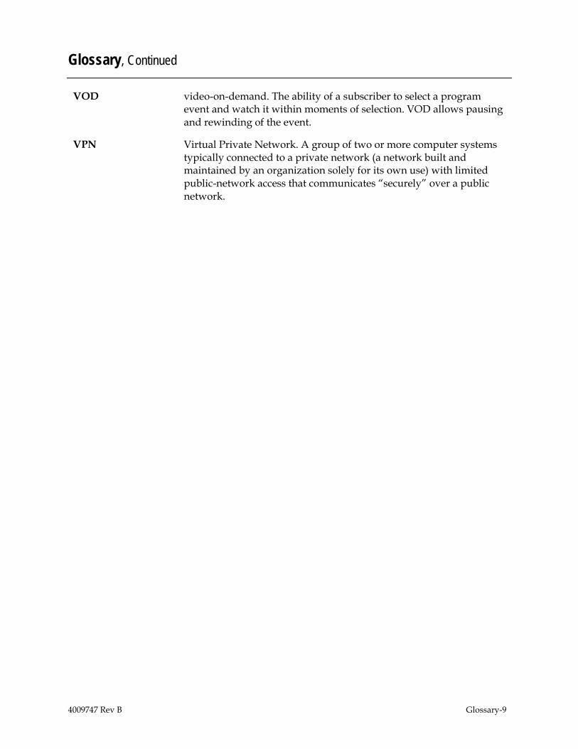
4009747 Rev B Glossary-9
Glossary, Continued
VOD video-on-demand. The ability of a subscriber to select a program event and watch it within moments of selection. VOD allows pausing and rewinding of the event.
VPN Virtual Private Network. A group of two or more computer systems typically connected to a private network (a network built and maintained by an organization solely for its own use) with limited public-network access that communicates “securely” over a public network.

Index
4009747 Rev B Index-1
add source to Selected Sources list, 6-6 AppServer Control Window
description, 1-6 example, 1-5
barkers, 4-15
channel map, place virtual channel on, 6-16 collectors, IPG, 5-3 Configure new BFS Server source ID, 6-11 create
new digital source for VCS, 6-3 PPV service, 4-5
create source HTML files, 6-12
DBDS and SARA Server, 1-3 define
PPV events, 4-12 PPV service, 4-2
delete IPG service name, 5-14 PPV event, 4-28 PPV service, 4-11 virtual channel, 6-17
digital source adding to Selected Sources list, 6-6 create for VCS, 6-3
disable tracing function, 7-5 DNCS Administrative Console Status
Window, 1-4 DNCS Administrative Console Window
example, 1-7 tabs, 1-8
DNCS Monitor Windows, 1-4 DNCS Administrative Console Status
Window, 1-4 DNCS Administrative Console Window
tabs, 1-8 dvd server
adding to BFS, 8-2 updating with new files, 8-4
edit IPG data, 5-19 enable tracing, 7-2 event
delete, 4-28 generate automatically, 4-18 generate IPPV, 4-18, 4-23 generate manually, 4-19, 4-23 generate RPPV, 4-18, 4-19 modify, 4-27 types, 4-18
foreign language support, 3-2
generate events manually, 4-19, 4-23 generate IPPV events
automatically, 4-18 manually, 4-23
generate RPPV events automatically, 4-18 manually, 4-19
HTML files create for VCS, 6-12 save for VCS, 6-14
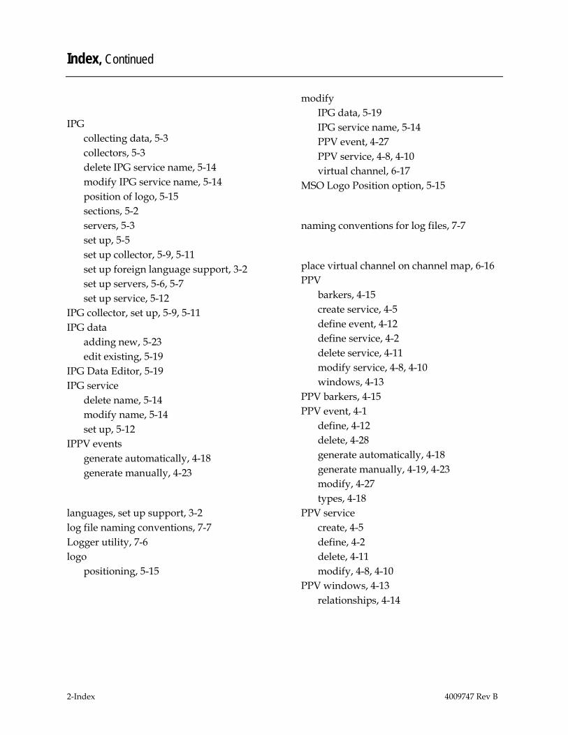
Index, Continued
2-Index 4009747 Rev B
IPG collecting data, 5-3 collectors, 5-3 delete IPG service name, 5-14 modify IPG service name, 5-14 position of logo, 5-15 sections, 5-2 servers, 5-3 set up, 5-5 set up collector, 5-9, 5-11 set up foreign language support, 3-2 set up servers, 5-6, 5-7 set up service, 5-12
IPG collector, set up, 5-9, 5-11 IPG data
adding new, 5-23 edit existing, 5-19
IPG Data Editor, 5-19 IPG service
delete name, 5-14 modify name, 5-14 set up, 5-12
IPPV events generate automatically, 4-18 generate manually, 4-23
languages, set up support, 3-2 log file naming conventions, 7-7 Logger utility, 7-6 logo
positioning, 5-15
modify IPG data, 5-19 IPG service name, 5-14 PPV event, 4-27 PPV service, 4-8, 4-10 virtual channel, 6-17
MSO Logo Position option, 5-15
naming conventions for log files, 7-7
place virtual channel on channel map, 6-16 PPV
barkers, 4-15 create service, 4-5 define event, 4-12 define service, 4-2 delete service, 4-11 modify service, 4-8, 4-10 windows, 4-13
PPV barkers, 4-15 PPV event, 4-1
define, 4-12 delete, 4-28 generate automatically, 4-18 generate manually, 4-19, 4-23 modify, 4-27 types, 4-18
PPV service create, 4-5 define, 4-2 delete, 4-11 modify, 4-8, 4-10
PPV windows, 4-13 relationships, 4-14
Index, Continued
4009747 Rev B Index-3
RPPV events generate automatically, 4-18 generate manually, 4-19
SARA Server and DBDS, 1-3 description, 1-2 power up workstation, 2-1, 2-2 processes, description, 1-6 start processes, 2-1, 2-2, 2-3
save the source HTML files, 6-14 Selected Sources list, add, 6-6 servers, IPG, 5-3 set up
IPG, 5-5 IPG collector, 5-9, 5-11 IPG servers, 5-6, 5-7 IPG service, 5-12 VCS, 6-15
trace.cfg, 7-2 tracing
disable, 7-5 enable, 7-2 log file naming conventions, 7-7 Logger utility, 7-6 trace.cfg, 7-2 understanding trace levels, 7-2 view log files, 7-6
VCS adding source to Selected Sources list, 6-
6 configure new BFS Server source ID, 6-
11 create new digital source, 6-3 create source HTML files, 6-12 save the source HTML files, 6-14 set up, 6-15
view tracing log files, 7-6 virtual channel, 6-1
create source HTML file, 6-12 delete, 6-17 modify, 6-17 place on channel map, 6-16 save the source HTML file, 6-14
Virtual Channel Service. See VCS
window AppServer Control, 1-5 DNCS Administrative Console, 1-7 DNCS Administrative Console tabs, 1-8 DNCS Aministrative Console Status, 1-4 DNCS monitor, 1-4

Cisco Systems, Inc. 5030 Sugarloaf Parkway, Box 465447 Lawrenceville, GA 30042
678 277-1120 800 722-2009
www.cisco.com This document includes various trademarks of Cisco Systems, Inc. Please see the Notices section of this document for a list of the Cisco Systems, Inc. trademarks used in this document. Product and service availability are subject to change without notice. ©2005, 2012 Cisco and/or its affiliates. All rights reserved. March 2012 Printed in USA
Part Number 4009747 Rev B