Embed Size (px)
Citation preview
SAP2000®
IntegratedFinite Element Analysis
andDesign of Structures
QUICK TUTORIALS
COMPUTERS &
STRUCTURES
INC.
Computers and Structures, Inc.Berkeley, California, USA
Version 7.0Revised October 1998

COPYRIGHT
The computer program SAP2000 and all associated documentation areproprietary and copyrighted products. Worldwide rights of ownershiprest with Computers and Structures, Inc. Unlicensed use of the programor reproduction of the documentation in any form, without prior writtenauthorization from Computers and Structures, Inc., is explicitly prohib-ited.
Further information and copies of this documentation may be obtainedfrom:
Computers and Structures, Inc.1995 University Avenue
Berkeley, California 94704 USA
tel: (510) 845-2177fax: (510) 845-4096
e-mail: [email protected]:www.csiberkeley.com
© Copyright Computers and Structures, Inc., 1978–1998.The CSI Logo is a registered trademark of Computers and Structures, Inc.SAP2000 is a registered trademark of Computers and Structures, Inc.Windows is a registered trademark of Microsoft Corporation

DISCLAIMER
CONSIDERABLE TIME, EFFORT AND EXPENSE HAVE GONEINTO THE DEVELOPMENT AND DOCUMENTATION OF SAP2000.THE PROGRAM HAS BEEN THOROUGHLY TESTED AND USED.IN USING THE PROGRAM, HOWEVER, THE USER ACCEPTS ANDUNDERSTANDS THAT NO WARRANTY IS EXPRESSED OR IM-PLIED BY THE DEVELOPERS OR THE DISTRIBUTORS ON THEACCURACY OR THE RELIABILITY OF THE PROGRAM.
THE USER MUST EXPLICITLY UNDERSTAND THE ASSUMP-TIONS OF THE PROGRAM AND MUST INDEPENDENTLY VERIFYTHE RESULTS.
ACKNOWLEDGMENT
Thanks are due to all of the numerous structural engineers, who over theyears have given valuable feedback that has contributed toward the en-hancement of this product to its current state.
Special recognition is due Dr. Edward L. Wilson, Professor Emeritus,University of California at Berkeley, who was responsible for the con-ception and development of the original SAP series of programs andwhose continued originality has produced many unique concepts thathave been implemented in this version.
Table of Contents
CHAPTER I Introduction 1Overview . . . . . . . . . . . . . . . . . . . . . . . . . . . . . . . . . 1
Organization . . . . . . . . . . . . . . . . . . . . . . . . . . . . . . . 2
Recommended Reading. . . . . . . . . . . . . . . . . . . . . . . . . . 2
CHAPTER II Basic Tutorial 3Overview . . . . . . . . . . . . . . . . . . . . . . . . . . . . . . . . . 3
Description of the Model . . . . . . . . . . . . . . . . . . . . . . . . . 4
Starting the Tutorial. . . . . . . . . . . . . . . . . . . . . . . . . . . . 4
Setting Up the Geometry . . . . . . . . . . . . . . . . . . . . . . . . . 6
Defining Structural Sections . . . . . . . . . . . . . . . . . . . . . . . 7
Assigning Member Sections . . . . . . . . . . . . . . . . . . . . . . . 9
Defining Load Cases. . . . . . . . . . . . . . . . . . . . . . . . . . . 11
Assigning Joint Loads . . . . . . . . . . . . . . . . . . . . . . . . . . 12
Analyzing the Model . . . . . . . . . . . . . . . . . . . . . . . . . . 14
Displaying the Deformed Shape. . . . . . . . . . . . . . . . . . . . . 15
Displaying Member Forces . . . . . . . . . . . . . . . . . . . . . . . 18
Design Stress Check . . . . . . . . . . . . . . . . . . . . . . . . . . . 20
Modifying the Structure . . . . . . . . . . . . . . . . . . . . . . . . . 21
Concluding Remarks . . . . . . . . . . . . . . . . . . . . . . . . . . 25
CHAPTER III Concrete Design Tutorial 27Overview. . . . . . . . . . . . . . . . . . . . . . . . . . . . . . . . . 27
Description of the Model . . . . . . . . . . . . . . . . . . . . . . . . 28
Starting the Tutorial . . . . . . . . . . . . . . . . . . . . . . . . . . . 30
Opening the Model Database File . . . . . . . . . . . . . . . . . . . . 31
i
Analyzing the Model . . . . . . . . . . . . . . . . . . . . . . . . . . 32
Selecting the Design Code. . . . . . . . . . . . . . . . . . . . . . . . 34
Starting Design . . . . . . . . . . . . . . . . . . . . . . . . . . . . . 34
Changing Member Properties . . . . . . . . . . . . . . . . . . . . . . 38
Concluding Remarks . . . . . . . . . . . . . . . . . . . . . . . . . . 43
CHAPTER IV Steel Design Tutorial 45Overview. . . . . . . . . . . . . . . . . . . . . . . . . . . . . . . . . 45
Description of the Model . . . . . . . . . . . . . . . . . . . . . . . . 46
Starting the Tutorial . . . . . . . . . . . . . . . . . . . . . . . . . . . 48
Opening the Model Database File . . . . . . . . . . . . . . . . . . . . 48
Analyzing the Model . . . . . . . . . . . . . . . . . . . . . . . . . . 50
Selecting the Design Code. . . . . . . . . . . . . . . . . . . . . . . . 51
Starting Design and Stress Check . . . . . . . . . . . . . . . . . . . . 52
Modifying Member Properties . . . . . . . . . . . . . . . . . . . . . 56
Selecting Sections Automatically . . . . . . . . . . . . . . . . . . . . 59
Re-analyzing with Updated Elements . . . . . . . . . . . . . . . . . . 62
Concluding Remarks . . . . . . . . . . . . . . . . . . . . . . . . . . 64
ii
SAP2000 Quick Tutorial
C h a p t e r I
Introduction
OverviewSAP2000 provides the user with options to create, modify, analyze and designstructural models, all from within the same user interface. This program featurespowerful and completely integrated modules for design of both steel and reinforcedconcrete structures. The program provides an interactive environment in which theuser can study the stress conditions, make appropriate changes, such as membersize revisions, and update the design without re-analyzing the structure.
This manual is intended to provide three quick tutorials aiming at giving the firsttime users hands-on experience. In the first tutorial, some of the basic modeling anddesign features of the SAP2000 are explored. Several features of SAP2000 steeland concrete design are explored in the subsequent two tutorials.
Step-by-step procedures for the modeling and design of the structures are outlinedin the tutorials. It is recommended that you actually perform these steps while read-ing the chapters.
Overview 1
OrganizationThis manual is organized in the following way:
Chapter II provides a quick tutorial aiming at giving the first time user hands-onexperience. Some of the basic features of SAP2000 are explored in this tutorial.
Chapter III provides a quick tutorial for steel design. Several of the basic featuresof SAP2000 steel design are explored in this tutorial.
Chapter IV provides a quick tutorial for concrete design. Several of the basic fea-tures of SAP2000 concrete design are explored in this tutorial.
Recommended ReadingIt is recommended that first time users read “The Graphical User Interface” chapterin theSAP2000 Getting Startedmanual before starting the tutorials given in thisbook. That chapter will provide basic understanding of the menus and buttons ofSAP2000 graphical user interface.
After completing the tutorials given in this book, the user might be interested in fol-lowing through the more detailed tutorials given in theSAP2000/NL-Push DetailedTutorial Including Pushover Analysis Manual.
2 Organization
SAP2000 Quick Tutorial
C h a p t e r II
Basic Tutorial
OverviewThis tutorial is aimed at giving the first-time user hands-on experience while de-scribing a few of the basic features and capabilities of SAP2000. It is assumed thatyou have read the chapter, “The Graphical User Interface” provided in theSAP2000Getting Startedmanual. It is recommended that you use the comprehensive on-line Help included in the program. You may also wish to refer to theSAP2000 BasicAnalysis Referencein the third part of this volume for more information about thestructural model.
As you become familiar with the program, you will realize that the order of some ofthe steps described here is immaterial. In other words, after some practice, you maychoose to perform the operations in a different order to set up and run the samemodel.
We will use the SAP2000 commands either from the Toolbars or from the menus.This is done intentionally to familiarize you with both methods. The Toolbars pro-vide quick access to commonly used features. All of the features available on theToolbars can also be accessed from the Menu Bar.
Overview 3
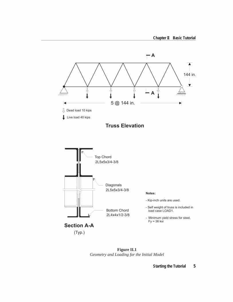
Description of the ModelThe model chosen for this tutorial is developed, analyzed, design-checked, and thenmodified. A simple two-dimensional five-bay truss of the “Warren” type is selectedfrom the program template, subjected to both dead and live point loads, and thenanalyzed for the two load cases. A design stress check is performed, in accordancewith AISC/ASD89, to examine the interaction stress ratios. The geometry and load-ing of the model are then modified, and the process is repeated.
The initial model is shown in Figure II.1. Kip-inch units are used. Structural steel(36 ksi yield strength) Double Angles are used throughout the model.
Starting the TutorialThe following topics describe the step-by-step procedure for creating and analyz-ing the truss model. It is recommended that you actually perform these steps usingthe program while you are reading this chapter.
The geometry is obtained from an available template. The templates represent anumber of common structural configurations. Remember that once the structuralgeometry has been set up, the order of steps is left to your discretion. Shortcuts willcome with experience.
Start the program by running SAP2000 from the Start Menu or from Program Man-ager, depending on your version of Windows. We will now proceed to develop themodel.
4 Description of the Model
SAP2000 Quick Tutorial
Starting the Tutorial 5
Chapter II Basic Tutorial
144 in.
5 @ 144 in.
Dead load 10 kips
Live load 40 kips
Truss Elevation
A
A
Section A-A
(Typ.)
2L5x5x3/4-3/8
Top Chord
Diagonals
2L5x5x3/4-3/8
Bottom Chord
2L4x4x1/2-3/8
Notes:
- Kip-inch units are used.
- Self weight of truss is included inload case LOAD1.
- Minimum yield stress for steel,Fy = 36 ksi
Figure II.1Geometry and Loading for the Initial Model
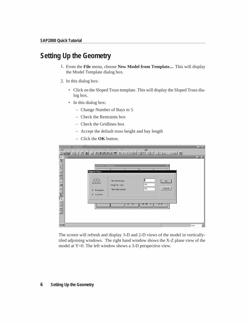
Setting Up the Geometry1. From theFile menu, chooseNew Model from Template.... This will display
the Model Template dialog box.
2. In this dialog box:
• Click on the Sloped Truss template. This will display the Sloped Truss dia-log box.
• In this dialog box:
– Change Number of Bays to 5
– Check the Restraints box
– Check the Gridlines box
– Accept the default truss height and bay length
– Click theOK button.
The screen will refresh and display 3-D and 2-D views of the model in vertically-tiled adjoining windows. The right hand window shows the X-Z plane view of themodel at Y=0. The left window shows a 3-D perspective view.
6 Setting Up the Geometry
SAP2000 Quick Tutorial
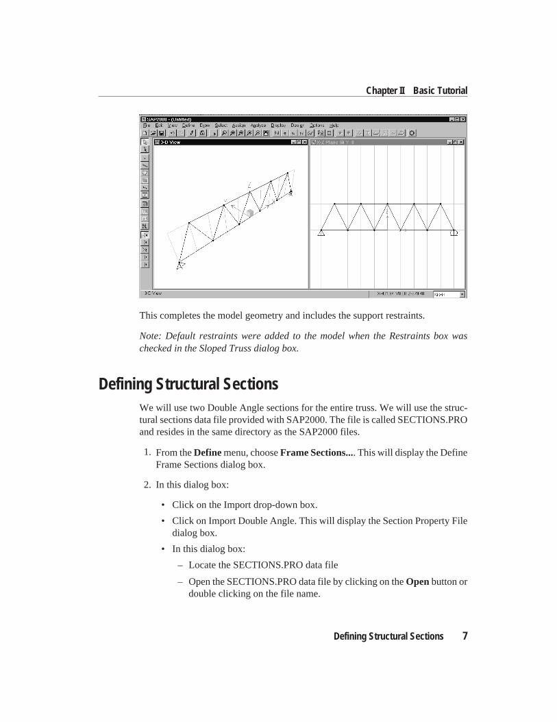
This completes the model geometry and includes the support restraints.
Note: Default restraints were added to the model when the Restraints box waschecked in the Sloped Truss dialog box.
Defining Structural SectionsWe will use two Double Angle sections for the entire truss. We will use the struc-tural sections data file provided with SAP2000. The file is called SECTIONS.PROand resides in the same directory as the SAP2000 files.
1. From theDefinemenu, chooseFrame Sections.... This will display the DefineFrame Sections dialog box.
2. In this dialog box:
• Click on the Import drop-down box.
• Click on Import Double Angle. This will display the Section Property Filedialog box.
• In this dialog box:
– Locate the SECTIONS.PRO data file
– Open the SECTIONS.PRO data file by clicking on theOpenbutton ordouble clicking on the file name.
Defining Structural Sections 7
Chapter II Basic Tutorial
– This will display a drop down list box showing all the Double Anglesections available in the data file.
Note: In a SAP2000 session you have only to locate and open the SEC-TIONS.PRO data file once. However, you have the option to select anotherfile at any time by choosingPreferencesin theOptions menu.
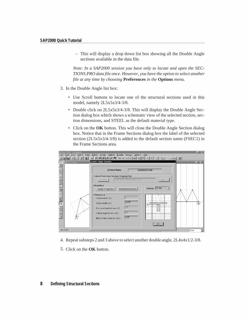
3. In the Double Angle list box:
• Use Scroll buttons to locate one of the structural sections used in thismodel, namely 2L5x5x3/4-3/8.
• Double click on 2L5x5x3/4-3/8. This will display the Double Angle Sec-tion dialog box which shows a schematic view of the selected section, sec-tion dimensions, and STEEL as the default material type.
• Click on theOK button. This will close the Double Angle Section dialogbox. Notice that in the Frame Sections dialog box the label of the selectedsection (2L5x5x3/4-3/8) is added to the default section name (FSEC1) inthe Frame Sections area.
4. Repeat substeps 2 and 3 above to select another double angle, 2L4x4x1/2-3/8.
5. Click on theOK button.
8 Defining Structural Sections
SAP2000 Quick Tutorial
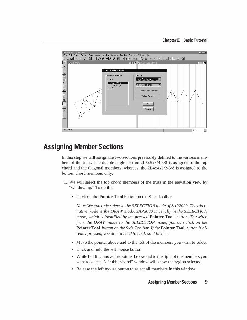
Assigning Member SectionsIn this step we will assign the two sections previously defined to the various mem-bers of the truss. The double angle section 2L5x5x3/4-3/8 is assigned to the topchord and the diagonal members, whereas, the 2L4x4x1/2-3/8 is assigned to thebottom chord members only.
1. We will select the top chord members of the truss in the elevation view by“windowing.” To do this:
• Click on thePointer Tool button on the Side Toolbar.
Note: We can only select in the SELECTION mode of SAP2000. The alter-native mode is the DRAW mode. SAP2000 is usually in the SELECTIONmode, which is identified by the pressedPointer Tool button. To switchfrom the DRAW mode to the SELECTION mode, you can click on thePointer Tool button on the Side Toolbar. If thePointer Tool button is al-ready pressed, you do not need to click on it further.
• Move the pointer above and to the left of the members you want to select
• Click and hold the left mouse button
• While holding, move the pointer below and to the right of the members youwant to select. A “rubber-band” window will show the region selected.
• Release the left mouse button to select all members in this window.
Assigning Member Sections 9
Chapter II Basic Tutorial
2. We will select the diagonal members by intersection. To do this:
• Click theSet Intersecting Line Select Modebutton on the Side Toolbar
• Move the pointer to the left of the members you want to select
• Click and hold the left mouse button
• While holding, move the pointer to the right of the members you want toselect. A “rubber-band” will show the intersecting line.
• Release the left mouse button to select all members that intersect this line.
The selection of all the top chord and the diagonal members of the truss is now com-plete. The selected Frame elements appear as dashed lines.
3. FromAssignmenu, chooseFrame, thenSections...from the submenu. Thiswill display the Define Frame Sections dialog box.
4. In this dialog box:
• Click on 2L5x5x3/4-3/8 in the Name area.
• Click on theOK button.
The display window in which the selection process was done is refreshed and thesection label is displayed on all members.
5. Select the bottom chord members by “windowing” as in substep 1 above.
6. Repeat substeps 3 and 4 to assign 2L4x4x1/2-3/8 to these members.
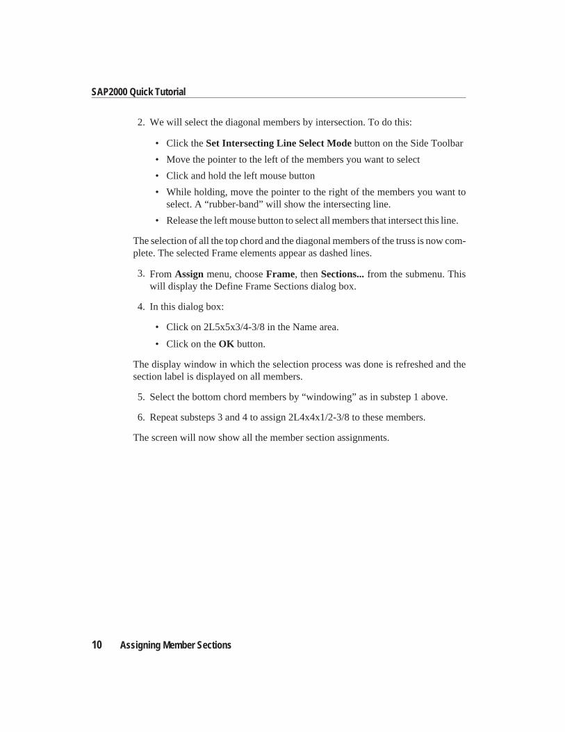
The screen will now show all the member section assignments.
10 Assigning Member Sections
SAP2000 Quick Tutorial
Note: You can always change the display attributes, e.g. increase the font size, etc.from thePreferences...in theOptions menu.
You may turn off the display of the section labels by selectingShow UndeformedShapefrom theDisplay menu.
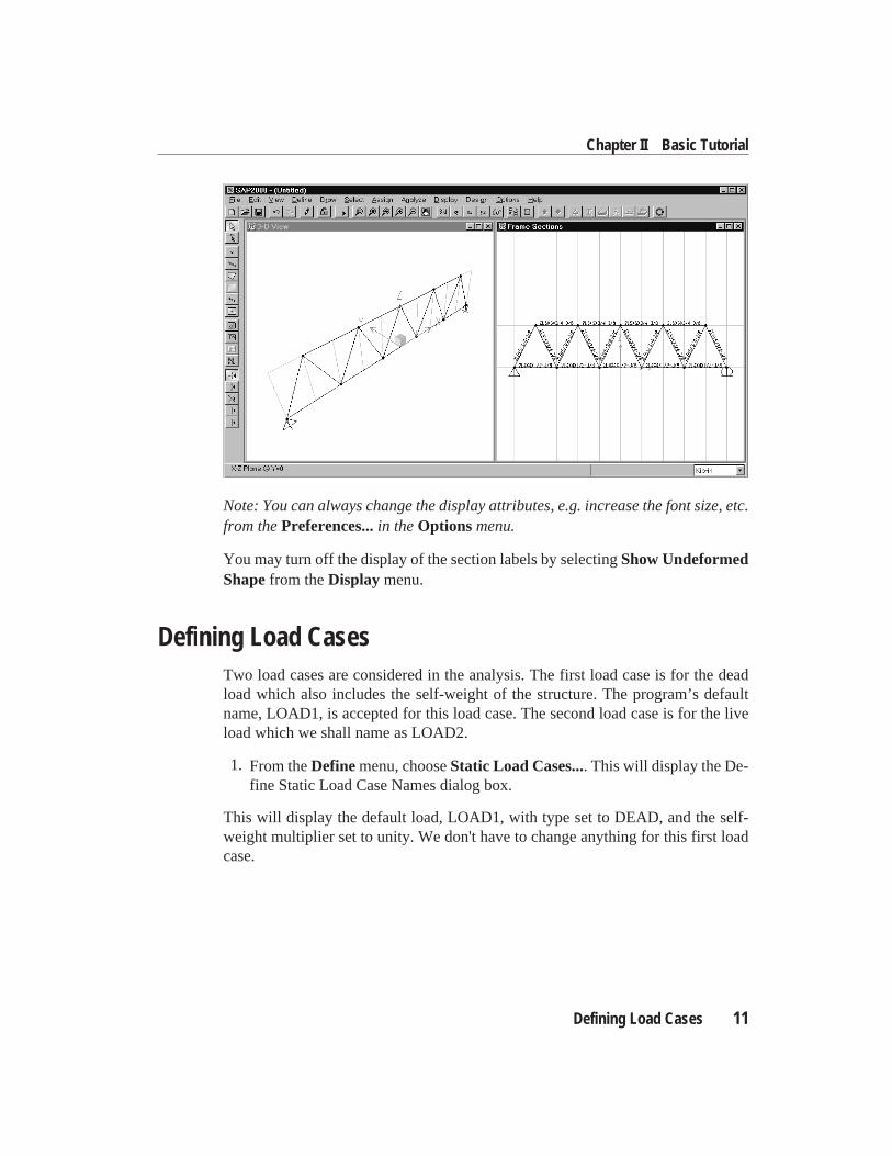
Defining Load CasesTwo load cases are considered in the analysis. The first load case is for the deadload which also includes the self-weight of the structure. The program’s defaultname, LOAD1, is accepted for this load case. The second load case is for the liveload which we shall name as LOAD2.
1. From theDefinemenu, chooseStatic Load Cases.... This will display the De-fine Static Load Case Names dialog box.
This will display the default load, LOAD1, with type set to DEAD, and the self-weight multiplier set to unity. We don't have to change anything for this first loadcase.
Defining Load Cases 11
Chapter II Basic Tutorial
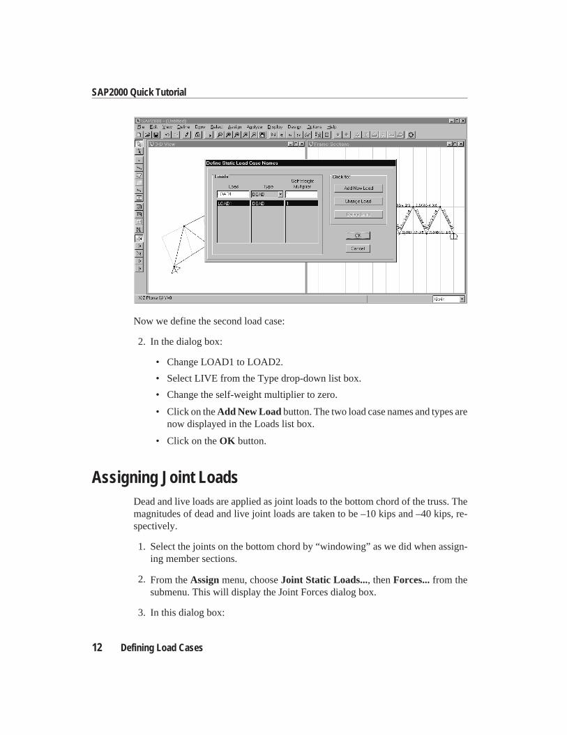
Now we define the second load case:
2. In the dialog box:
• Change LOAD1 to LOAD2.
• Select LIVE from the Type drop-down list box.
• Change the self-weight multiplier to zero.
• Click on theAdd New Loadbutton. The two load case names and types arenow displayed in the Loads list box.
• Click on theOK button.
Assigning Joint LoadsDead and live loads are applied as joint loads to the bottom chord of the truss. Themagnitudes of dead and live joint loads are taken to be –10 kips and –40 kips, re-spectively.
1. Select the joints on the bottom chord by “windowing” as we did when assign-ing member sections.
2. From theAssignmenu, chooseJoint Static Loads..., thenForces...from thesubmenu. This will display the Joint Forces dialog box.
3. In this dialog box:
12 Defining Load Cases
SAP2000 Quick Tutorial
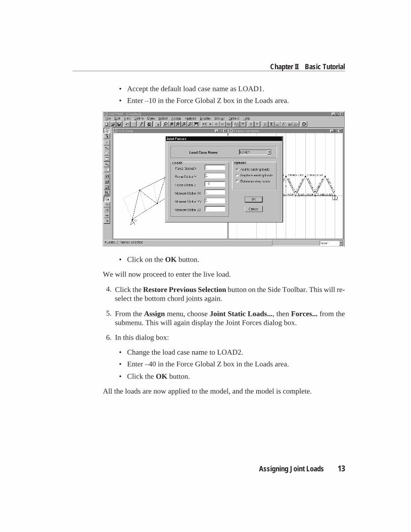
• Accept the default load case name as LOAD1.
• Enter –10 in the Force Global Z box in the Loads area.
• Click on theOK button.
We will now proceed to enter the live load.
4. Click theRestore Previous Selectionbutton on the Side Toolbar. This will re-select the bottom chord joints again.
5. From theAssignmenu, chooseJoint Static Loads..., thenForces...from thesubmenu. This will again display the Joint Forces dialog box.
6. In this dialog box:
• Change the load case name to LOAD2.
• Enter –40 in the Force Global Z box in the Loads area.
• Click theOK button.
All the loads are now applied to the model, and the model is complete.
Assigning Joint Loads 13
Chapter II Basic Tutorial
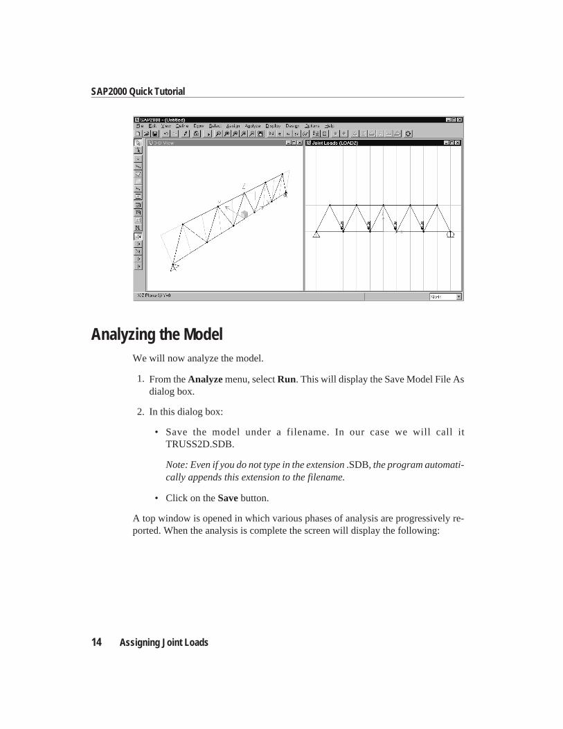
Analyzing the ModelWe will now analyze the model.
1. From theAnalyzemenu, selectRun. This will display the Save Model File Asdialog box.
2. In this dialog box:
• Save the model under a filename. In our case we will call itTRUSS2D.SDB.
Note: Even if you do not type in the extension.SDB, the program automati-cally appends this extension to the filename.
• Click on theSavebutton.
A top window is opened in which various phases of analysis are progressively re-ported. When the analysis is complete the screen will display the following:
14 Assigning Joint Loads
SAP2000 Quick Tutorial
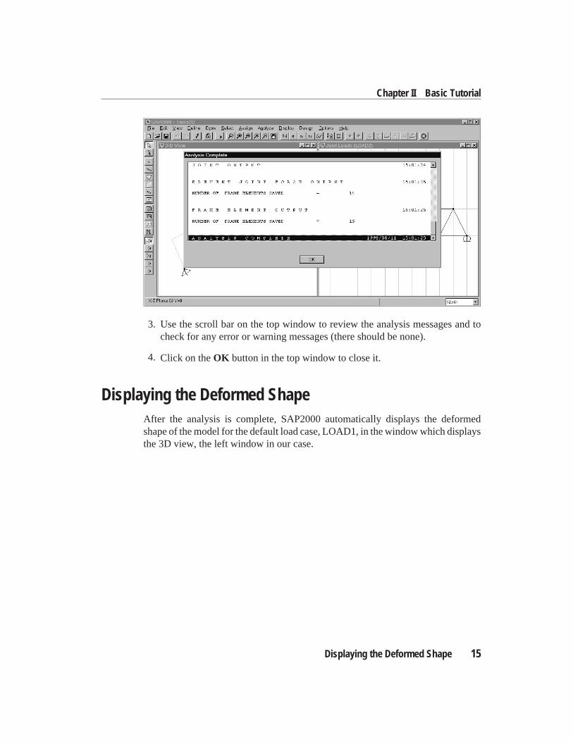
3. Use the scroll bar on the top window to review the analysis messages and tocheck for any error or warning messages (there should be none).
4. Click on theOK button in the top window to close it.
Displaying the Deformed ShapeAfter the analysis is complete, SAP2000 automatically displays the deformedshape of the model for the default load case, LOAD1, in the window which displaysthe 3D view, the left window in our case.
Displaying the Deformed Shape 15
Chapter II Basic Tutorial
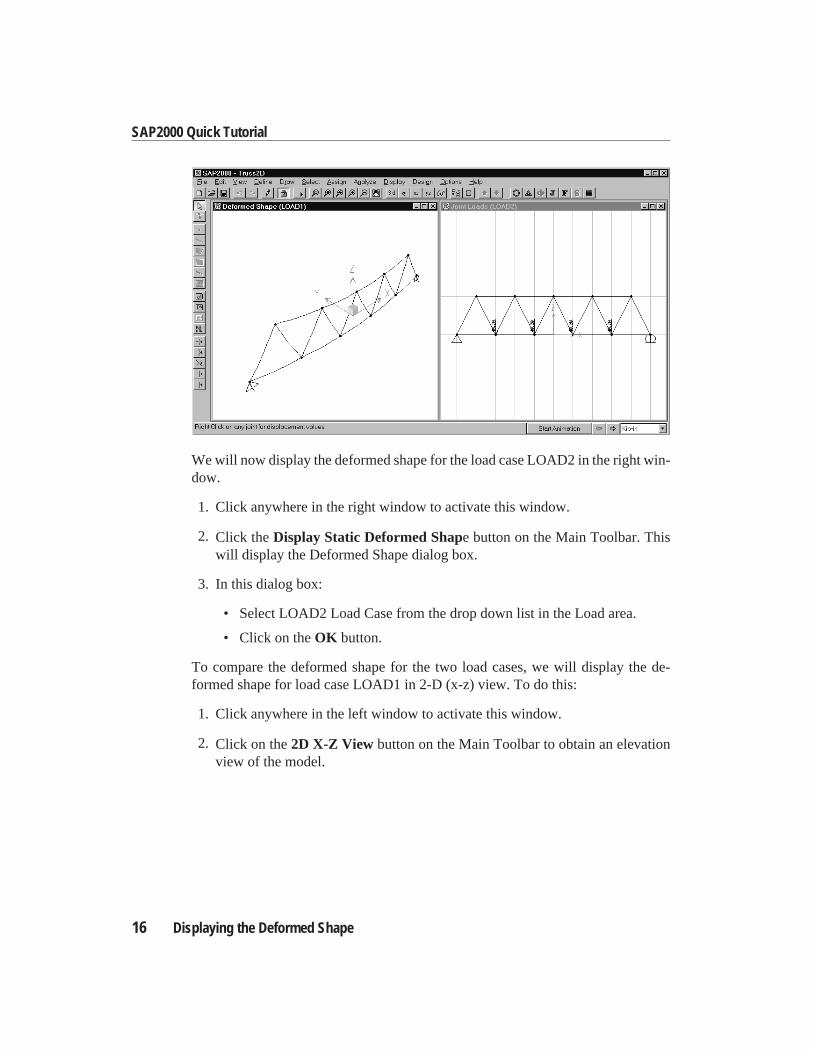
We will now display the deformed shape for the load case LOAD2 in the right win-dow.
1. Click anywhere in the right window to activate this window.
2. Click theDisplay Static Deformed Shape button on the Main Toolbar. Thiswill display the Deformed Shape dialog box.
3. In this dialog box:
• Select LOAD2 Load Case from the drop down list in the Load area.
• Click on theOK button.
To compare the deformed shape for the two load cases, we will display the de-formed shape for load case LOAD1 in 2-D (x-z) view. To do this:
1. Click anywhere in the left window to activate this window.
2. Click on the2D X-Z View button on the Main Toolbar to obtain an elevationview of the model.
16 Displaying the Deformed Shape
SAP2000 Quick Tutorial
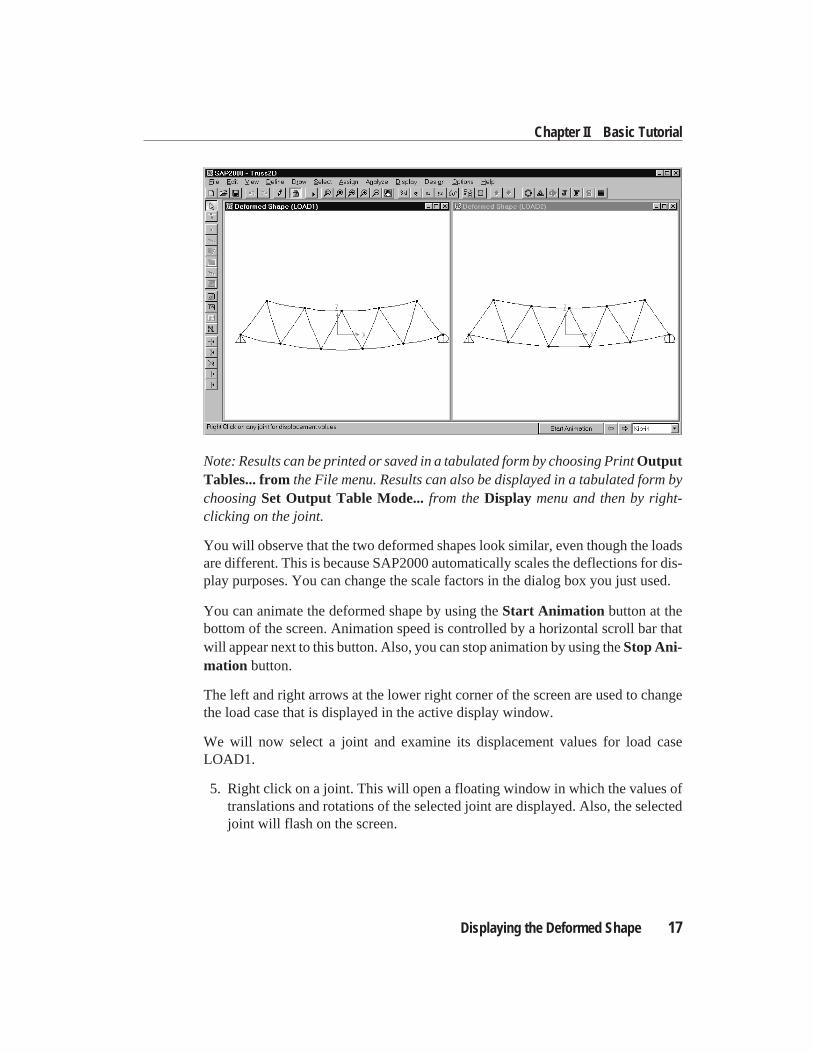
Note: Results can be printed or saved in a tabulated form by choosing PrintOutputTables... fromthe File menu. Results can also be displayed in a tabulated form bychoosingSet Output Table Mode... from theDisplay menu and then by right-clicking on the joint.
You will observe that the two deformed shapes look similar, even though the loadsare different. This is because SAP2000 automatically scales the deflections for dis-play purposes. You can change the scale factors in the dialog box you just used.
You can animate the deformed shape by using theStart Animation button at thebottom of the screen. Animation speed is controlled by a horizontal scroll bar thatwill appear next to this button. Also, you can stop animation by using theStop Ani-mation button.
The left and right arrows at the lower right corner of the screen are used to changethe load case that is displayed in the active display window.
We will now select a joint and examine its displacement values for load caseLOAD1.
5. Right click on a joint. This will open a floating window in which the values oftranslations and rotations of the selected joint are displayed. Also, the selectedjoint will flash on the screen.
Displaying the Deformed Shape 17
Chapter II Basic Tutorial
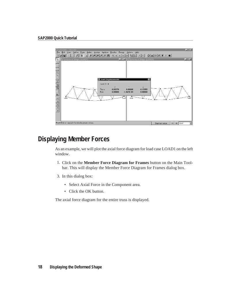
Displaying Member ForcesAs an example, we will plot the axial force diagram for load case LOAD1 on the leftwindow.
1. Click on theMember Force Diagram for Framesbutton on the Main Tool-bar. This will display the Member Force Diagram for Frames dialog box.
3. In this dialog box:
• Select Axial Force in the Component area.
• Click the OK button.
The axial force diagram for the entire truss is displayed.
18 Displaying the Deformed Shape
SAP2000 Quick Tutorial
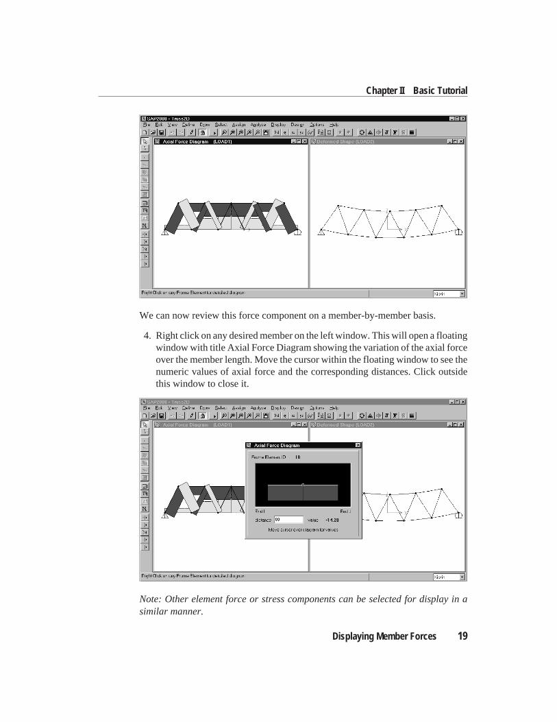
We can now review this force component on a member-by-member basis.
4. Right click on any desired member on the left window. This will open a floatingwindow with title Axial Force Diagram showing the variation of the axial forceover the member length. Move the cursor within the floating window to see thenumeric values of axial force and the corresponding distances. Click outsidethis window to close it.
Note: Other element force or stress components can be selected for display in asimilar manner.
Displaying Member Forces 19
Chapter II Basic Tutorial
Note: Results can be printed or saved in a tabulated form by choosing PrintOutputTables... fromthe File menu. Results can also be displayed in a tabulated form bychoosingSet Output Table Mode... from theDisplay menu and then by right-clicking on the element.
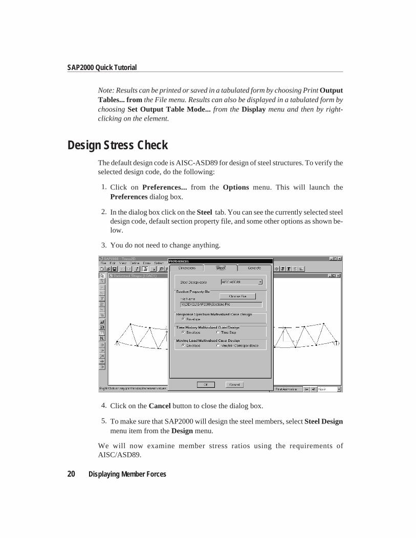
Design Stress CheckThe default design code is AISC-ASD89 for design of steel structures. To verify theselected design code, do the following:
1. Click on Preferences...from the Options menu. This will launch thePreferencesdialog box.
2. In the dialog box click on theSteel tab. You can see the currently selected steeldesign code, default section property file, and some other options as shown be-low.
3. You do not need to change anything.
4. Click on theCancelbutton to close the dialog box.
5. To make sure that SAP2000 will design the steel members, selectSteel Designmenu item from theDesignmenu.
We will now examine member stress ratios using the requirements ofAISC/ASD89.
20 Displaying Member Forces
SAP2000 Quick Tutorial
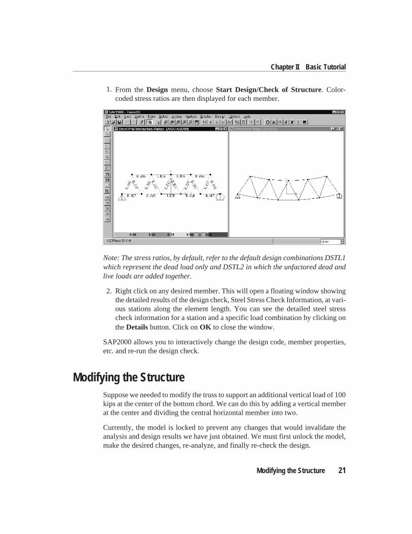
1. From theDesign menu, chooseStart Design/Check of Structure. Color-coded stress ratios are then displayed for each member.
Note: The stress ratios, by default, refer to the default design combinations DSTL1which represent the dead load only and DSTL2 in which the unfactored dead andlive loads are added together.
2. Right click on any desired member. This will open a floating window showingthe detailed results of the design check, Steel Stress Check Information, at vari-ous stations along the element length. You can see the detailed steel stresscheck information for a station and a specific load combination by clicking ontheDetailsbutton. Click onOK to close the window.
SAP2000 allows you to interactively change the design code, member properties,etc. and re-run the design check.
Modifying the StructureSuppose we needed to modify the truss to support an additional vertical load of 100kips at the center of the bottom chord. We can do this by adding a vertical memberat the center and dividing the central horizontal member into two.
Currently, the model is locked to prevent any changes that would invalidate theanalysis and design results we have just obtained. We must first unlock the model,make the desired changes, re-analyze, and finally re-check the design.
Modifying the Structure 21
Chapter II Basic Tutorial
1. Click on theLock/Unlock Model button on the Main Toolbar to unlock themodel.
2. You will be warned that unlocking the model will delete all analysis results.Click on OK to acknowledge this.
For illustration purposes, we will use two different methods to draw the new Frameelements. Either method could be used for all of the added elements in this example.
2. Click on theQuick Draw Frame Element button on the Side Toolbar, or se-lect it from theDraw menu. An element will be drawn each time you click on agrid line.
3. Click the vertical gridline at the center of the model between the top and bottomchords to get the vertical member.
It may now appear that the truss is complete. However, the new vertical member isnot actually connected to the horizontal member on the bottom chord. This can eas-ily be seen in a shrunken-element view.
4. Click on theElement Shrink Toggleon the Main Toolbar.
5. In order to see more clearly:
• SelectShow Grid from theView menu to turn off the grid
• SelectShow Axesfrom theView menu to turn off the global axes
• Click on theRubber Band Zoombutton on the Main Toolbar
• In the active Display Window, click and drag a window to enclose the mid-dle part of the structure. The contents of this window will be magnified tofill the Display Window.
22 Modifying the Structure
SAP2000 Quick Tutorial
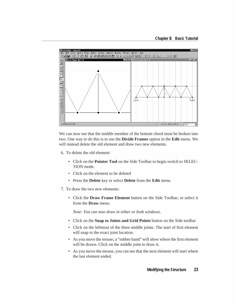
We can now see that the middle member of the bottom chord must be broken intotwo. One way to do this is to use theDivide Framesoption in theEdit menu. Wewill instead delete the old element and draw two new elements.
6. To delete the old element:
• Click on thePointer Tool on the Side Toolbar to begin switch to SELEC-TION mode.
• Click on the element to be deleted
• Press theDeletekey or selectDeletefrom theEdit menu
7. To draw the two new elements:
• Click theDraw Frame Element button on the Side Toolbar, or select itfrom theDraw menu.
Note: You can now draw in either or both windows.
• Click on theSnap to Joints and Grid Pointsbutton on the Side toolbar
• Click on the leftmost of the three middle joints. The start of first elementwill snap to the exact joint location.
• As you move the mouse, a “rubber band” will show where the first elementwill be drawn. Click on the middle joint to draw it.
• As you move the mouse, you can see that the next element will start wherethe last element ended.
Modifying the Structure 23
Chapter II Basic Tutorial
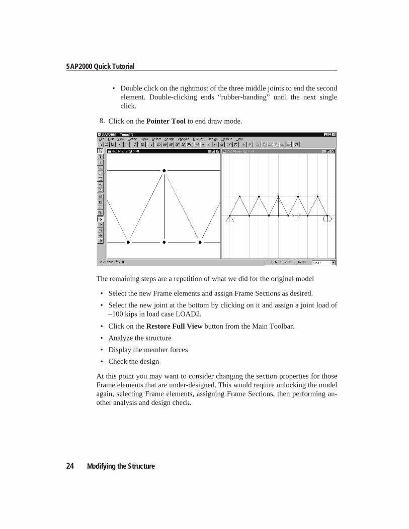
• Double click on the rightmost of the three middle joints to end the secondelement. Double-clicking ends “rubber-banding” until the next singleclick.
8. Click on thePointer Tool to end draw mode.
The remaining steps are a repetition of what we did for the original model
• Select the new Frame elements and assign Frame Sections as desired.
• Select the new joint at the bottom by clicking on it and assign a joint load of–100 kips in load case LOAD2.
• Click on theRestore Full Viewbutton from the Main Toolbar.
• Analyze the structure
• Display the member forces
• Check the design
At this point you may want to consider changing the section properties for thoseFrame elements that are under-designed. This would require unlocking the modelagain, selecting Frame elements, assigning Frame Sections, then performing an-other analysis and design check.
24 Modifying the Structure
SAP2000 Quick Tutorial
Concluding RemarksThis marks the end of the quick tour of SAP2000. The intent has been to highlightand demonstrate a few of the basic features. Feel free to experiment and exploreother options. Additional information is available within the Help menu.
Concluding Remarks 25
Chapter II Basic Tutorial

.
C h a p t e r III
Concrete Design Tutorial
OverviewSeveral of the basic features of SAP2000 concrete design are explored in this tuto-rial. This introduction is aimed at giving the first time user hands-on experience de-signing concrete frames with SAP2000. The program allows you to select fromseveral U.S. and international codes to design and review concrete structures. Acomprehensive on-line Help is included in the program for your quick reference. Itis assumed that you have a working knowledge of concrete design procedures andare reasonably familiar with the current codes of practice and their underlying de-sign concepts.
We will access the SAP2000 commands from both the Main Toolbar and the SideToolbar and from the menus. The Toolbars, however, provide quick access to mostcommonly used features available from the menus.
In the assignment sequence, there are two important points you must remember.First, you have to define an entity before you can assign an attribute to it, and sec-ond, you have to select member(s) before you can assign new attributes or modifyold ones.
Overview 27
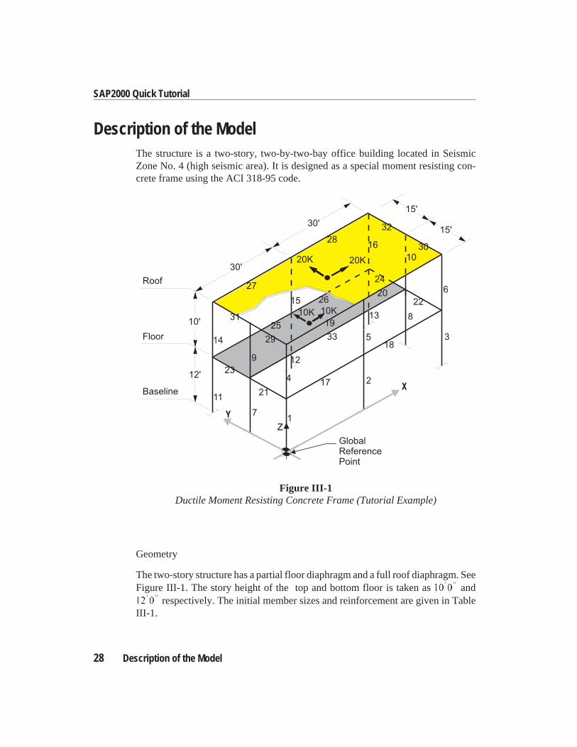
Description of the ModelThe structure is a two-story, two-by-two-bay office building located in SeismicZone No. 4 (high seismic area). It is designed as a special moment resisting con-crete frame using the ACI 318-95 code.
Geometry
The two-story structure has a partial floor diaphragm and a full roof diaphragm. SeeFigure III-1. The story height of the top and bottom floor is taken as10 0
′ ′′ and12 0
′ ′′ respectively. The initial member sizes and reinforcement are given in TableIII-1.
28 Description of the Model
SAP2000 Quick Tutorial
GlobalReferencePoint
1
2
3
4
5
6
12
14
15
16
13
17
202226
27
28
29
30
31
32
33
25
24
23
21
19
18
7
8
9
11
1020K 20K
10K10K
15'
15'
30'
30'
10'
12'
Roof
Floor
Baseline
Z
Figure III-1Ductile Moment Resisting Concrete Frame (Tutorial Example)
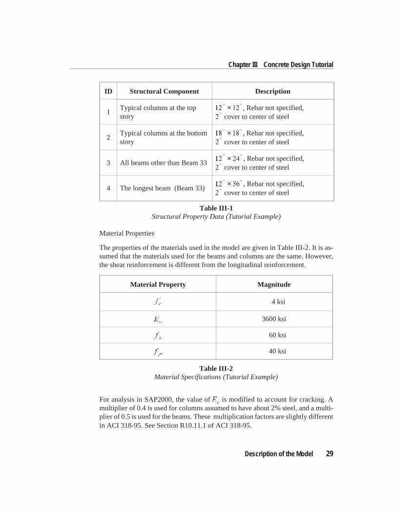
Material Properties
The properties of the materials used in the model are given in Table III-2. It is as-sumed that the materials used for the beams and columns are the same. However,the shear reinforcement is different from the longitudinal reinforcement.
For analysis in SAP2000, the value ofEc
is modified to account for cracking. Amultiplier of 0.4 is used for columns assumed to have about 2% steel, and a multi-plier of 0.5 is used for the beams. These multiplication factors are slightly differentin ACI 318-95. See Section R10.11.1 of ACI 318-95.
Description of the Model 29
Chapter III Concrete Design Tutorial
Material Property Magnitude
fc
′ 4 ksi
Ec
3600 ksi
fy
60 ksi
fys
40 ksi
Table III-2Material Specifications (Tutorial Example)
ID Structural Component Description
1Typical columns at the topstory
12 12′′ ′′× , Rebar not specified,
2′′ cover to center of steel
2Typical columns at the bottomstory
18 18′′ ′′× , Rebar not specified,
2′′ cover to center of steel
3 All beams other than Beam 3312 24
′′ ′′× , Rebar not specified,2
′′ cover to center of steel
4 The longest beam (Beam 33)12 36
′′ ′′× , Rebar not specified,2
′′ cover to center of steel
Table III-1Structural Property Data (Tutorial Example)
Load Cases
Four load cases are considered in the analysis. The dead and live loads are definedas load cases DL and LL respectively. The lateral seismic loads, in turn, are desig-nated as QX and QY respectively.
The dead and live loads are simplified as line loads on the beams. The equivalentstatic seismic forces are applied as lateral loads at the centroids of the diaphragms:
Load case 1 : DLC 1.0 kip/ft on all beams which are connected to the diaphragmalong the X-direction (Self-weight included)
Load case 2 : LLC 0.5 kip/ft on all beams which are connected to the diaphragmalong the X-direction
Load case 3 : QXC Static equivalent earthquake force in the X-direction
Load case 4 : QYC Static equivalent earthquake force in the Y-direction
Analysis
Two diaphragm constraints are applied for the two diaphragms at the two floors.These constraints prevent in-plane relative displacements of the nodes at each floor.The lateral earthquake loads are assumed to be applied at the centroid of the dia-phragm. A P-∆ analysis is carried out with a load level of 0.75 (1.4 DL + 1.7 LL)/ϕas recommended in the chapter “Design for ACI 318-95” of theSAP2000 ConcreteDesign Manual, whereϕ is taken as 0.75.
Design
The design is performed in accordance with ACI 318-95. Kip-in units are used forthe model. The input database file for this model isEXCONC.SDB. This is sup-plied as part of the SAP2000 package.
Starting the TutorialA step-by-step procedure for the design of the model is outlined below. It is recom-mended that you actually perform these steps while reading this chapter. We as-sume that you have successfully started the program. You can do this by runningSAP2000 from the Start Menu.
30 Description of the Model
SAP2000 Quick Tutorial
In this tutorial, whenever possible, we will use the Toolbars to access various op-tions quickly. Most of the features available on the Toolbars can also be accessedfrom the menus. Use the on-line Help or refer to theSAP2000 Getting Startedman-ual for a detailed description of the SAP2000 screen.
The input database file for the model (EXCONC.SDB) is in the EXAMPLES sub-directory under the main directory where the program has been installed. In this ex-ample, the analysis model is already created. This tutorial gives the highlights of thedesign phase. You are assumed to be familiar with creating and editing structuralmodels using SAP2000.
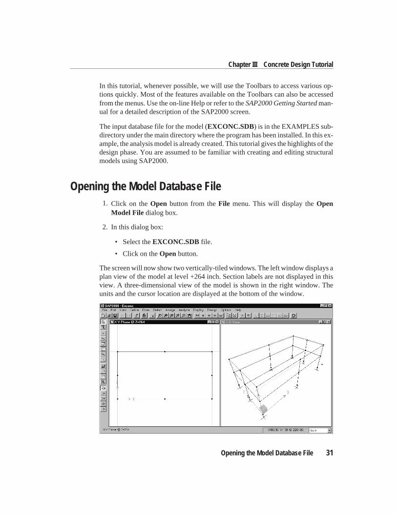
Opening the Model Database File1. Click on theOpen button from theFile menu. This will display theOpen
Model File dialog box.
2. In this dialog box:
• Select theEXCONC.SDB file.
• Click on theOpenbutton.
The screen will now show two vertically-tiled windows. The left window displays aplan view of the model at level +264 inch. Section labels are not displayed in thisview. A three-dimensional view of the model is shown in the right window. Theunits and the cursor location are displayed at the bottom of the window.
Opening the Model Database File 31
Chapter III Concrete Design Tutorial
Note: when working with multiple windows, clicking anywhere in a particular win-dow will activate that window.
Before we proceed further, we will make a copy of the data file by saving the modelunder a new name, say, TUTOR1.SDB. We will use the copy during the tutorial andleave the original file unaltered.
3. From theFile menu, chooseSave As.... This will display theSave Model FileAs dialog box.
4. In this dialog box:
• Enter new filename, Tutor1.SDB.
Note: Even if you do not type in the extension .SDB, the program automati-cally appends this extension to the filename.
• Click on theSavebutton.
The new name is displayed in the Main Title Bar.
Analyzing the ModelWe will now analyze the model. Before analyzing the model we need to set the P-∆force and other parameters for P-∆ analysis. To do this:
1. Select theSet Options...button in theAnalyze menu. This will immediatelybring up theAnalysis Optionsdialog box. In this dialog box:
• Check theInclude P-Deltabox.
• Click on theSet P-Delta Parametersbutton. This will bring up theP-Delta Parametersdialog box. In this dialog box:
– Set maximum iterations to 5.
– Change the DL scale factor to 1.4 and clickModify .
– Click on theLoad Casedrop down arrow.
– Select LL.
– Change the LL scale factor to 1.7 and clickAdd.
– Click OK to close theP-Delta Parametersdialog box
• Click OK to closeAnalysis Optionsdialog box.
2. Click on theRun Analysisbutton on the Main Toolbar.
32 Opening the Model Database File
SAP2000 Quick Tutorial
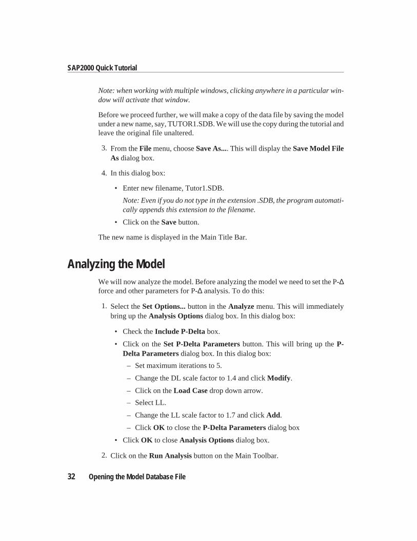
A top window is opened in which various phases of analysis are progressively re-ported. When the analysis is complete the screen will display the following:
3. Use the scroll bar on the top window to review the analysis messages and tocheck for any error or warning messages. In our case there should be none.
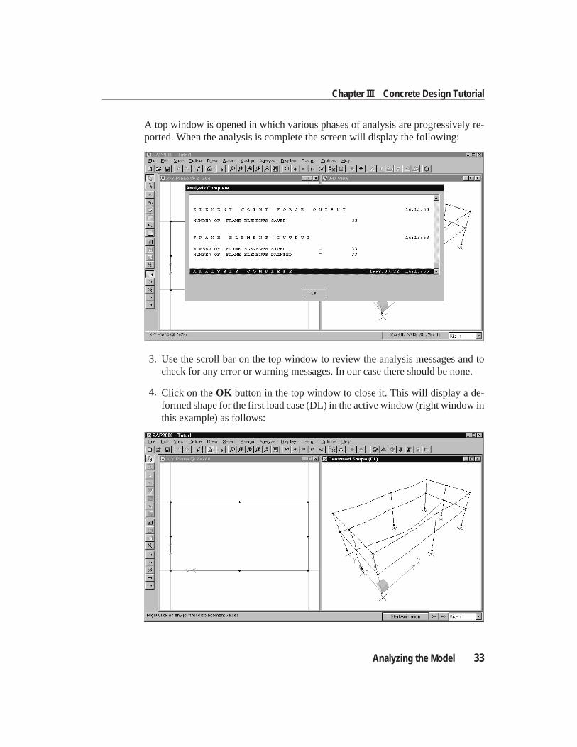
4. Click on theOK button in the top window to close it. This will display a de-formed shape for the first load case (DL) in the active window (right window inthis example) as follows:
Analyzing the Model 33
Chapter III Concrete Design Tutorial
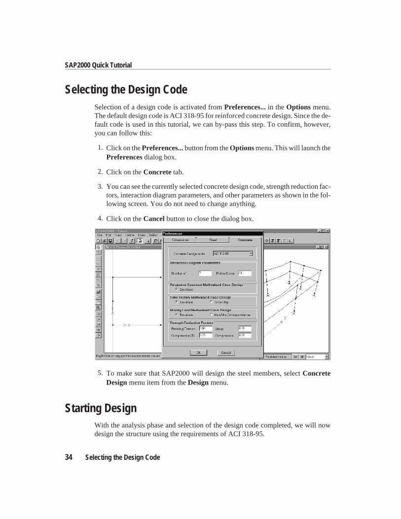
Selecting the Design CodeSelection of a design code is activated fromPreferences...in theOptions menu.The default design code is ACI 318-95 for reinforced concrete design. Since the de-fault code is used in this tutorial, we can by-pass this step. To confirm, however,you can follow this:
1. Click on thePreferences...button from theOptionsmenu. This will launch thePreferencesdialog box.
2. Click on theConcretetab.
3. You can see the currently selected concrete design code, strength reduction fac-tors, interaction diagram parameters, and other parameters as shown in the fol-lowing screen. You do not need to change anything.
4. Click on theCancelbutton to close the dialog box.
5. To make sure that SAP2000 will design the steel members, selectConcreteDesignmenu item from theDesignmenu.
Starting DesignWith the analysis phase and selection of the design code completed, we will nowdesign the structure using the requirements of ACI 318-95.
34 Selecting the Design Code
SAP2000 Quick Tutorial
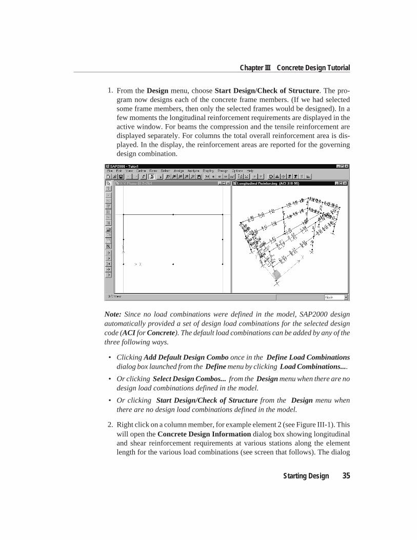
1. From theDesignmenu, chooseStart Design/Check of Structure. The pro-gram now designs each of the concrete frame members. (If we had selectedsome frame members, then only the selected frames would be designed). In afew moments the longitudinal reinforcement requirements are displayed in theactive window. For beams the compression and the tensile reinforcement aredisplayed separately. For columns the total overall reinforcement area is dis-played. In the display, the reinforcement areas are reported for the governingdesign combination.
Note: Since no load combinations were defined in the model, SAP2000 designautomatically provided a set of design load combinations for the selected designcode (ACI for Concrete). The default load combinations can be added by any of thethree following ways.
• ClickingAdd Default Design Comboonce in theDefine Load Combinationsdialog box launched from theDefinemenu by clickingLoad Combinations....
• Or clicking Select Design Combos...from theDesignmenu when there are nodesign load combinations defined in the model.
• Or clicking Start Design/Check of Structurefrom the Designmenu whenthere are no design load combinations defined in the model.
2. Right click on a column member, for example element 2 (see Figure III-1). Thiswill open theConcrete Design Informationdialog box showing longitudinaland shear reinforcement requirements at various stations along the elementlength for the various load combinations (see screen that follows). The dialog
Starting Design 35
Chapter III Concrete Design Tutorial
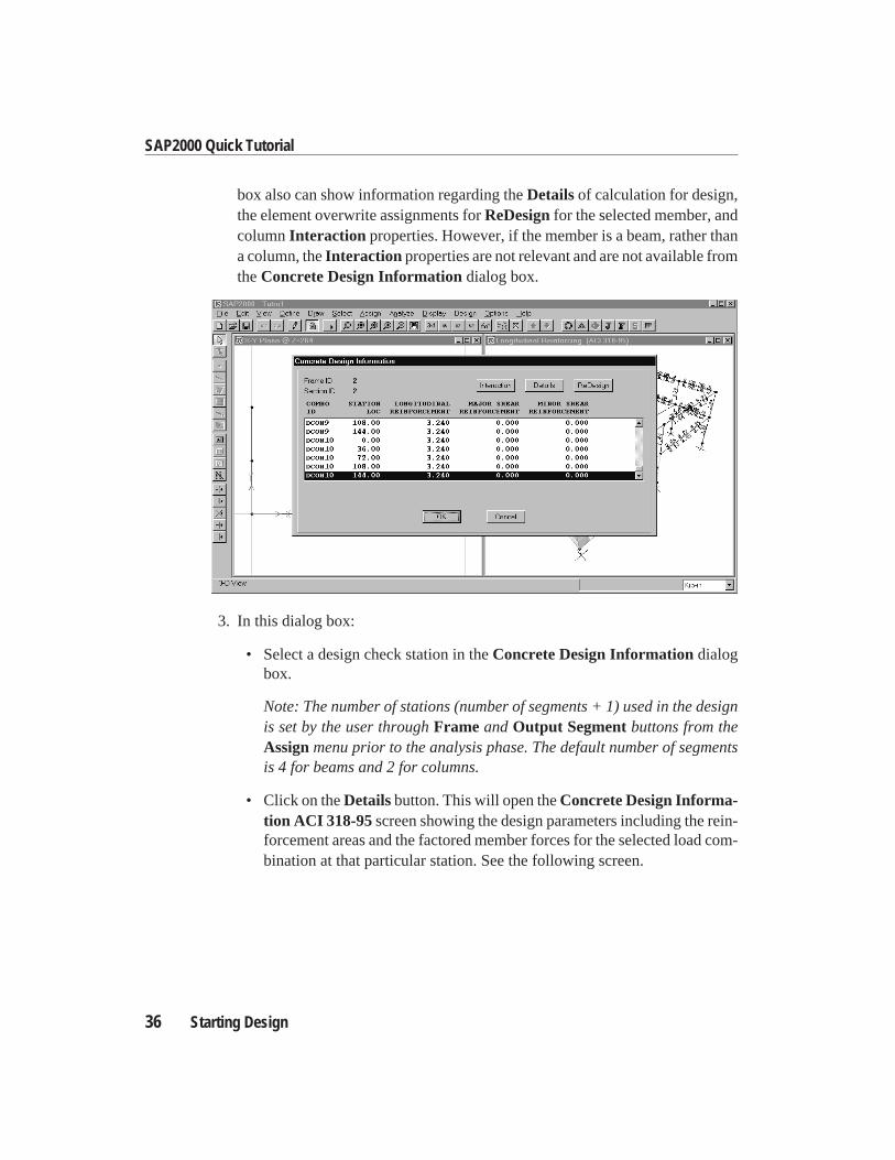
box also can show information regarding theDetailsof calculation for design,the element overwrite assignments forReDesignfor the selected member, andcolumnInteraction properties. However, if the member is a beam, rather thana column, theInteraction properties are not relevant and are not available fromtheConcrete Design Informationdialog box.
3. In this dialog box:
• Select a design check station in theConcrete Design Informationdialogbox.
Note: The number of stations (number of segments + 1) used in the designis set by the user throughFrame andOutput Segmentbuttons from theAssignmenu prior to the analysis phase. The default number of segmentsis 4 for beams and 2 for columns.
• Click on theDetailsbutton. This will open theConcrete Design Informa-tion ACI 318-95 screen showing the design parameters including the rein-forcement areas and the factored member forces for the selected load com-bination at that particular station. See the following screen.
36 Starting Design
SAP2000 Quick Tutorial
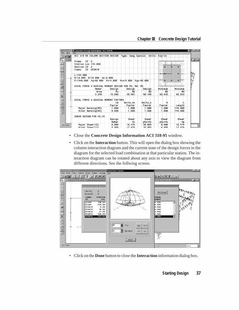
• Close theConcrete Design Information ACI 318-95window.
• Click on theInteraction button. This will open the dialog box showing thecolumn interaction diagram and the current state of the design forces in thediagram for the selected load combination at that particular station. The in-teraction diagram can be rotated about any axis to view the diagram fromdifferent directions. See the follwing screen.
• Click on theDonebutton to close theInteraction information dialog box.
Starting Design 37
Chapter III Concrete Design Tutorial
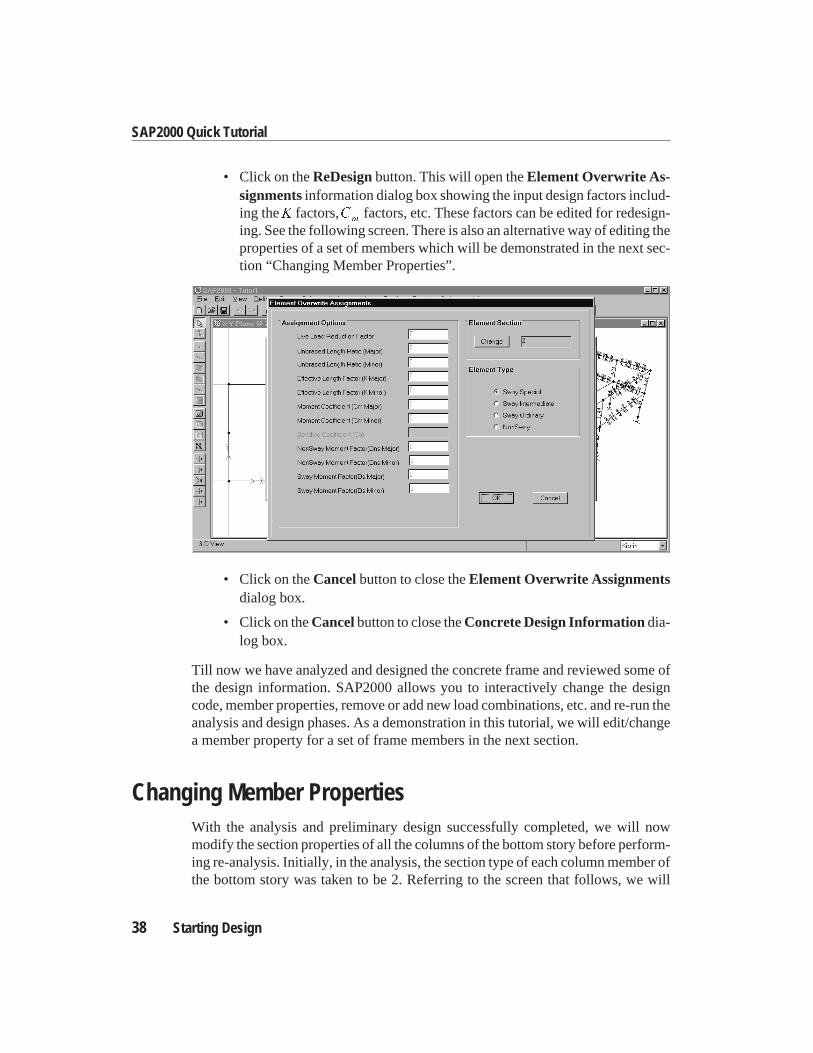
• Click on theReDesignbutton. This will open theElement Overwrite As-signmentsinformation dialog box showing the input design factors includ-ing theK factors,C
mfactors, etc. These factors can be edited for redesign-
ing. See the following screen. There is also an alternative way of editing theproperties of a set of members which will be demonstrated in the next sec-tion “Changing Member Properties”.
• Click on theCancelbutton to close theElement Overwrite Assignmentsdialog box.
• Click on theCancelbutton to close theConcrete Design Informationdia-log box.
Till now we have analyzed and designed the concrete frame and reviewed some ofthe design information. SAP2000 allows you to interactively change the designcode, member properties, remove or add new load combinations, etc. and re-run theanalysis and design phases. As a demonstration in this tutorial, we will edit/changea member property for a set of frame members in the next section.
Changing Member PropertiesWith the analysis and preliminary design successfully completed, we will nowmodify the section properties of all the columns of the bottom story before perform-ing re-analysis. Initially, in the analysis, the section type of each column member ofthe bottom story was taken to be 2. Referring to the screen that follows, we will
38 Starting Design
SAP2000 Quick Tutorial
change the section type of every column at the bottom story to be 1. Note that thereare already four previously defined section types in the model which were namednumerically as 1, 2, 3, and 4. In order to make these changes, we will change theview in the right window to make all the columns visible for selection. Notice thatthis window is currently showing the longitudinal reinforcing from the previous de-sign.
1. Click on theShow Undeformed Shapebutton from the Main Toolbar.
2. Click on the2D View (xz) button from the Main Toolbar for an elevation view.
3. Click on thePerspective Togglebutton from the Main Toolbar. This will dis-play a 3D view. All columns except the middle two will be visible. These twocolumns will be overlapping each other. To look at them better, we need to ro-tate the model about a vertical axis.
4. Click on theSet 3D View ...button on theView menu. Increase theplan ViewDirection Angle from 270 to 300 on theSet 3D Viewpopup window and thenclick on theOK button.
Now, with all the columns visible, we can select and modify their design section in-formation. Remember, SAP2000 maintains two sets of information for sections.One is for analysis and the other is for design. Changing section type here will af-fect the design section only. To update the analysis section, you need to explicitlyrequest an update of the analysis information from the current design state using themenu itemUpdate Analysis Sectionsin theDesignmenu.
5. To see the current setting of Design Sections do the following:
• Click on theDisplay Design Info ...menu item from theDesignmenu. Se-lect the Design Input option button.
• Select Design Sectionsfrom the drop-down list.
• Click OK .
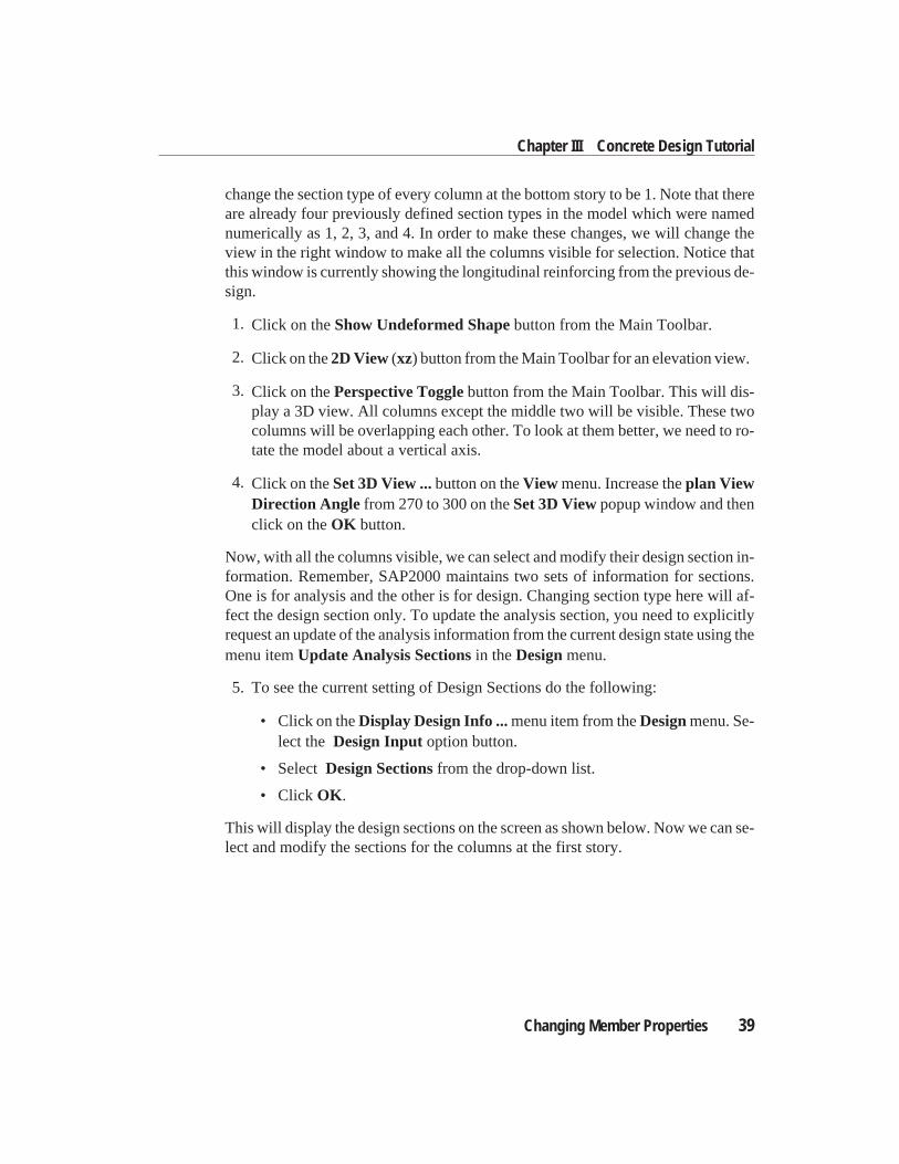
This will display the design sections on the screen as shown below. Now we can se-lect and modify the sections for the columns at the first story.
Changing Member Properties 39
Chapter III Concrete Design Tutorial
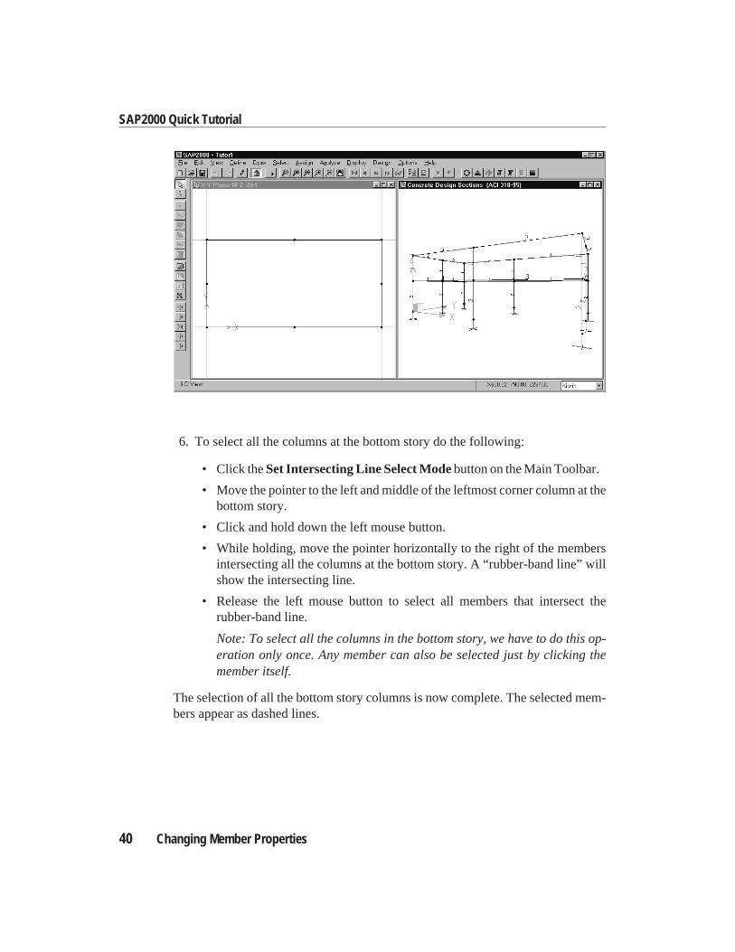
6. To select all the columns at the bottom story do the following:
• Click theSet Intersecting Line Select Modebutton on the Main Toolbar.
• Move the pointer to the left and middle of the leftmost corner column at thebottom story.
• Click and hold down the left mouse button.
• While holding, move the pointer horizontally to the right of the membersintersecting all the columns at the bottom story. A “rubber-band line” willshow the intersecting line.
• Release the left mouse button to select all members that intersect therubber-band line.
Note: To select all the columns in the bottom story, we have to do this op-eration only once. Any member can also be selected just by clicking themember itself.
The selection of all the bottom story columns is now complete. The selected mem-bers appear as dashed lines.
40 Changing Member Properties
SAP2000 Quick Tutorial
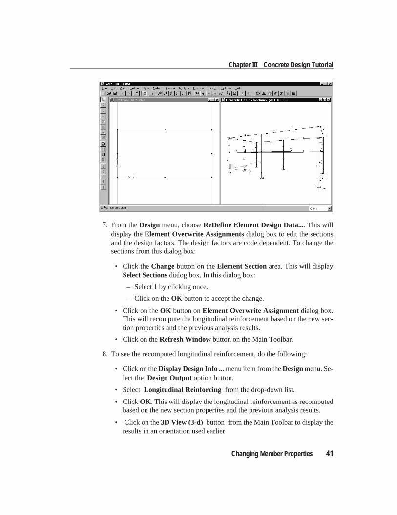
7. From theDesignmenu, chooseReDefine Element Design Data.... This willdisplay theElement Overwrite Assignmentsdialog box to edit the sectionsand the design factors. The design factors are code dependent. To change thesections from this dialog box:
• Click theChangebutton on theElement Sectionarea. This will displaySelect Sectionsdialog box. In this dialog box:
– Select 1 by clicking once.
– Click on theOK button to accept the change.
• Click on theOK button onElement Overwrite Assignmentdialog box.This will recompute the longitudinal reinforcement based on the new sec-tion properties and the previous analysis results.
• Click on theRefresh Windowbutton on the Main Toolbar.
8. To see the recomputed longitudinal reinforcement, do the following:
• Click on theDisplay Design Info ...menu item from theDesignmenu. Se-lect the Design Outputoption button.
• Select Longitudinal Reinforcing from the drop-down list.
• Click OK . This will display the longitudinal reinforcement as recomputedbased on the new section properties and the previous analysis results.
• Click on the3D View (3-d) button from the Main Toolbar to display theresults in an orientation used earlier.
Changing Member Properties 41
Chapter III Concrete Design Tutorial
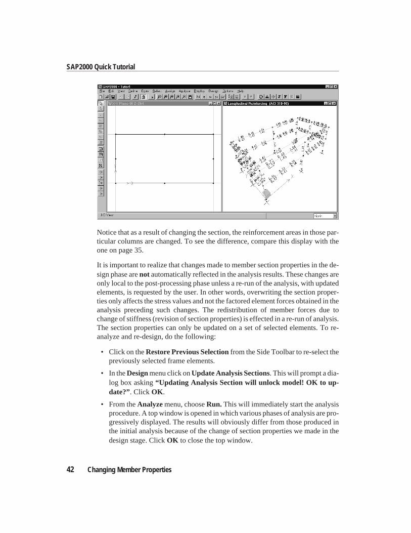
Notice that as a result of changing the section, the reinforcement areas in those par-ticular columns are changed. To see the difference, compare this display with theone on page 35.
It is important to realize that changes made to member section properties in the de-sign phase arenot automatically reflected in the analysis results. These changes areonly local to the post-processing phase unless a re-run of the analysis, with updatedelements, is requested by the user. In other words, overwriting the section proper-ties only affects the stress values and not the factored element forces obtained in theanalysis preceding such changes. The redistribution of member forces due tochange of stiffness (revision of section properties) is effected in a re-run of analysis.The section properties can only be updated on a set of selected elements. To re-analyze and re-design, do the following:
• Click on theRestore Previous Selectionfrom the Side Toolbar to re-select thepreviously selected frame elements.
• In theDesignmenu click onUpdate Analysis Sections. This will prompt a dia-log box asking“Updating Analysis Section will unlock model! OK to up-date?”. Click OK .
• From theAnalyzemenu, chooseRun. This will immediately start the analysisprocedure. A top window is opened in which various phases of analysis are pro-gressively displayed. The results will obviously differ from those produced inthe initial analysis because of the change of section properties we made in thedesign stage. ClickOK to close the top window.
42 Changing Member Properties
SAP2000 Quick Tutorial
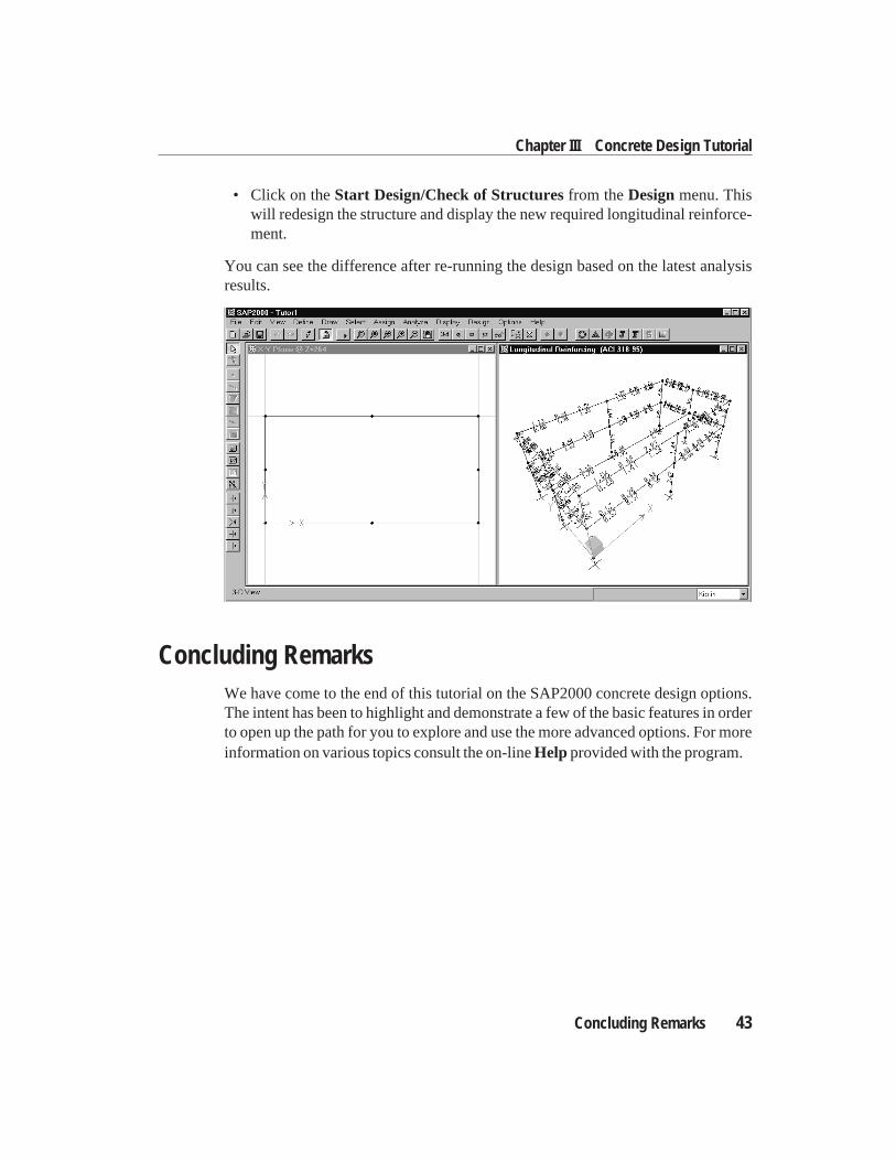
• Click on theStart Design/Check of Structuresfrom theDesignmenu. Thiswill redesign the structure and display the new required longitudinal reinforce-ment.
You can see the difference after re-running the design based on the latest analysisresults.
Concluding RemarksWe have come to the end of this tutorial on the SAP2000 concrete design options.The intent has been to highlight and demonstrate a few of the basic features in orderto open up the path for you to explore and use the more advanced options. For moreinformation on various topics consult the on-lineHelp provided with the program.
Concluding Remarks 43
Chapter III Concrete Design Tutorial

.
C h a p t e r IV
Steel Design Tutorial
OverviewSeveral of the basic features of SAP2000 steel design are explored in this tutorial.This tutorial is aimed at giving the first time user hands-on experience. The pro-gram allows you to select from several U.S. and international codes to stress checkand design a steel structure. It is assumed that you have a working knowledge ofsteel design procedures and are reasonably familiar with the current codes of prac-tice and their underlying design concepts. A comprehensive on-line Help is in-cluded in the program for your quick reference.
We will access the SAP2000 commands from both the Main Toolbar and the SideToolbar and from the menus. The Toolbars, however, provide quick access to mostcommonly used features available from the menus.
In the assignment sequence, there are two important points you must remember.First, you have to define an entity before you can assign an attribute to it, and sec-ond, you have to select member(s) before you can assign new attributes or modifyold ones.
Overview 45
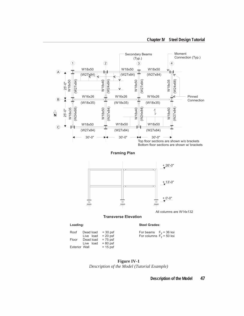
Description of the ModelThe structure is a two-story, two-by-three-bay office building. The frame will bedesigned in accordance with the AISC-LRFD93 code. Earthquake induced force isconsidered in the analysis and design of this frame. However, special requirementsfor the design of moment resisting ductile steel frames are not currently imple-mented in SAP2000.
Geometry
The moment frame is of structural steel as shown in Figure IV-1. The second floorhas metal deck and lightweight concrete fill, whereas the roof has metal deck only.Typical story height is taken as13 0
′ ′′ . The initial member sizes are given in FigureIV-1.
Material Properties
Material specifications are:
Beams and girders: ASTM A36 (Fy
= 36 ksi)Columns: ASTM A572 (F
y= 50 ksi)
Load Cases
Four load cases are considered in the analysisC DL, LL, QX, and QY. The deadand live loads are defined as the load cases DL and LL respectively. The lateralseismic loads, in turn, are designated as the load cases QX and QY.
The dead and live loads are applied as beam span loads based on the loading intensi-ties given below:
Roof Dead load = 30 psfLive load = 20 psf
Floor Dead load = 75 psfLive load = 80 psf
Ext. Wall Dead load = 15 psf
Equivalent static seismic forces are applied as lateral joint loads in the global X andglobal Y directions, separately. The total base shear in each direction is computedas 51 kips.
46 Description of the Model
SAP2000 Quick Tutorial
Description of the Model 47
Chapter IV Steel Design Tutorial
Framing Plan
Transverse Elevation
25
'-0
"2
5'-0
"
30'-0" 30'-0"30'-0"
Secondary Beams
(Typ.)
Loading: Steel Grades:
Roof Dead load = 30 psf For beams F = 36 ksiLive load = 20 psf For columns F = 50 ksi
Floor Dead load = 75 psfLive load = 80 psf
Exterior Wall = 15 psf
PinnedConnection
MomentConnection (Typ.)
All columns are W14x132
+ 0'-0"
+ 13'-0"
+ 26'-0"
N
A
B
C
1 2 3 4
W18x50
(W18x35)
W18x50W18x50
W18x50W18x50
W1
8x5
0
W1
8x5
0
W1
8x3
5
W1
8x5
0
W1
8x4
0
W1
8x5
0
W1
8x4
0
W1
8x3
5
W16x26 W16x26W16x26
(W18x35)(W18x35)
(W27x84)
(W27x84)
W18x50
(W27x84)(W27x84)
(W27x84)(W27x84)(W
27
x8
4)
(W2
4x6
8)
(W2
4x6
8)
(W2
7x8
4)
(W2
4x8
4)
(W2
4x8
4)
(W2
7x8
4)
(W2
7x8
4)
Top floor sections are shown w/o bracketsBottom floor sections are shown w/ brackets
Figure IV-1Description of the Model (Tutorial Example)
Analysis
Two diaphragm constraints are applied for the two diaphragms at the two floor lev-els. These constraints prevent in-plane relative displacements of the nodes at eachfloor. The lateral earthquake loads are applied at nodal points on the floor levels. AP-∆ analysis is carried out with a load combination of 1.2 DL + 0.5 LL as describedin Chapter “Check/Design for AISC-LRFD93”. The initial unbraced length is takenas the full member length.
Design
The stress check and design are performed in accordance with AISC-LRFD93.Kip-in units are used. The input data file for this model isEXSTL.SDB. This issupplied as part of the SAP2000 package.
Starting the TutorialA step-by-step procedure for the stress check and design of the model is outlinedbelow. It is recommended that you actually perform these steps while reading thischapter. We assume that you have successfully started the program. You can do thisby running SAP2000 from the Start Menu of the Windows operating system.
In this tutorial we will typically use the Toolbars to access various options quickly.Most of the features available on the Toolbars can also be accessed from the MenuBar. Use the on-line Help or refer to the chapter “The Graphical User Interface” inSAP2000 Getting Startedmanual for a detailed description of the SAP2000 screen.
The input data file for the model (EXSTL.SDB) is in the EXAMPLES subdirectoryunder the directory where the program has been installed. A section property file ofnameSECTIONS.PRO is also required for the tutorial. The SECTIONS.PRO fileis also available in the directory where the program has been installed.
Opening the Model Database File1. Click on theOpenbutton in theFile menu. This will display theOpen Model
File dialog box.
2. In this dialog box:
• Select theEXSTL.SDB file.
• Click on theOpenbutton.
48 Description of the Model
SAP2000 Quick Tutorial
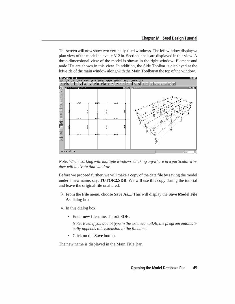
The screen will now show two vertically-tiled windows. The left window displays aplan view of the model at level + 312 in. Section labels are displayed in this view. Athree-dimensional view of the model is shown in the right window. Element andnode IDs are shown in this view. In addition, the Side Toolbar is displayed at theleft-side of the main window along with the Main Toolbar at the top of the window.
Note: When working with multiple windows, clicking anywhere in a particular win-dow will activate that window.
Before we proceed further, we will make a copy of the data file by saving the modelunder a new name, say,TUTOR2.SDB. We will use this copy during the tutorialand leave the original file unaltered.
3. From theFile menu, chooseSave As.... This will display theSave Model FileAs dialog box.
4. In this dialog box:
• Enter new filename, Tutor2.SDB.
Note: Even if you do not type in the extension .SDB, the program automati-cally appends this extension to the filename.
• Click on theSavebutton.
The new name is displayed in the Main Title Bar.
Opening the Model Database File 49
Chapter IV Steel Design Tutorial
Analyzing the ModelWe will now analyze the model. Before analyzing the model we need to set the P-∆force (1.2 DL + 0.5 LL) and other parameters for P-∆ analysis. To do this:
1. Select theSet Options...menu item in theAnalyze menu. This will immedi-ately bring up theAnalysis Optionsdialog box. In this dialog box:
• Click theInclude P-Deltacheck box.
• Click on theSet P-Delta Parametersbutton. This will bring up theP-Delta Parametersdialog box. In this dialog box:
– Set maximum iteration to 5.
– Change the DL scale factor to 1.2 and clickModify .
– Click on theLoad Casedrop down arrow.
– Select LL.
– Change the LL scale factor to 0.5 and clickAdd.
– Click OK to close theP-Delta Parametersdialog box
• Click OK to close theAnalysis Optionsdialog box.
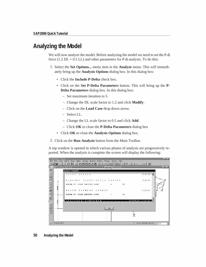
2. Click on theRun Analysisbutton from the Main Toolbar.
A top window is opened in which various phases of analysis are progressively re-ported. When the analysis is complete the screen will display the following:
50 Analyzing the Model
SAP2000 Quick Tutorial
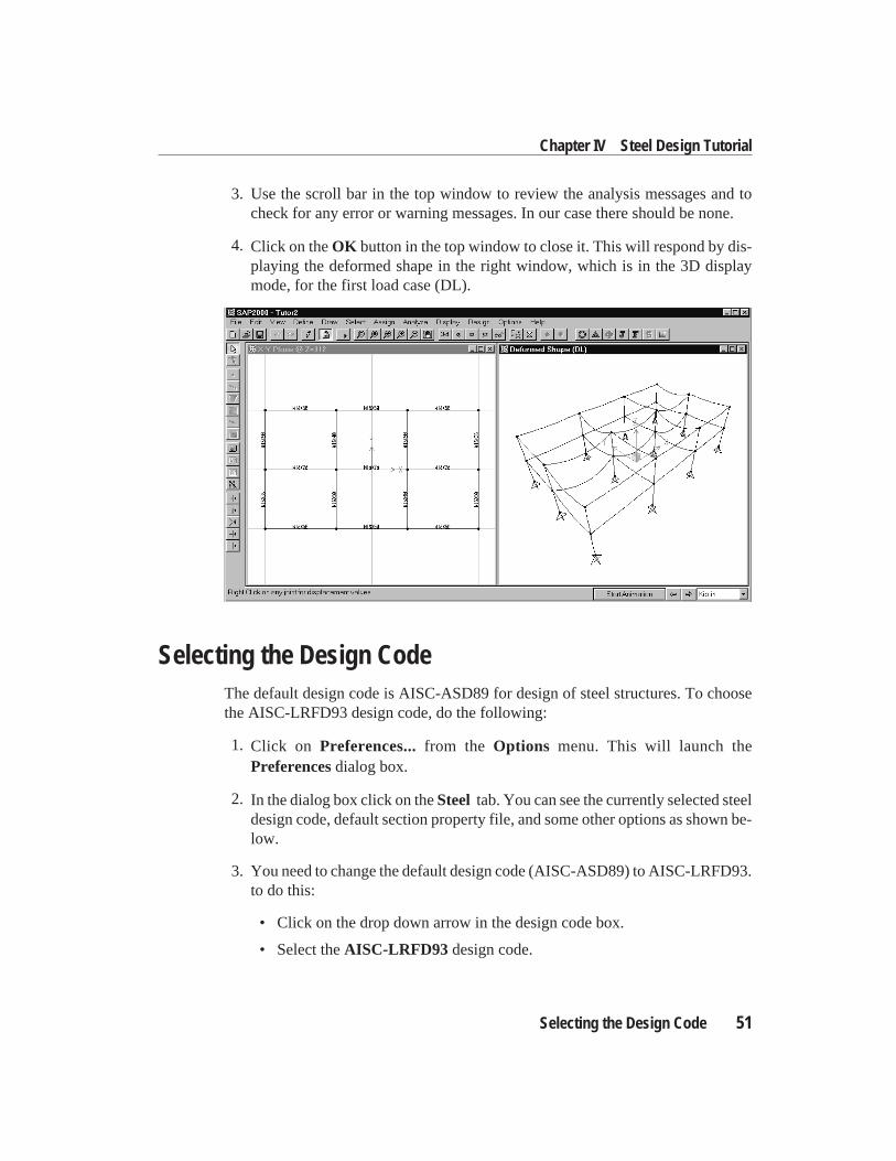
3. Use the scroll bar in the top window to review the analysis messages and tocheck for any error or warning messages. In our case there should be none.
4. Click on theOK button in the top window to close it. This will respond by dis-playing the deformed shape in the right window, which is in the 3D displaymode, for the first load case (DL).
Selecting the Design CodeThe default design code is AISC-ASD89 for design of steel structures. To choosethe AISC-LRFD93 design code, do the following:
1. Click on Preferences...from the Options menu. This will launch thePreferencesdialog box.
2. In the dialog box click on theSteel tab. You can see the currently selected steeldesign code, default section property file, and some other options as shown be-low.
3. You need to change the default design code (AISC-ASD89) to AISC-LRFD93.to do this:
• Click on the drop down arrow in the design code box.
• Select theAISC-LRFD93 design code.
Selecting the Design Code 51
Chapter IV Steel Design Tutorial
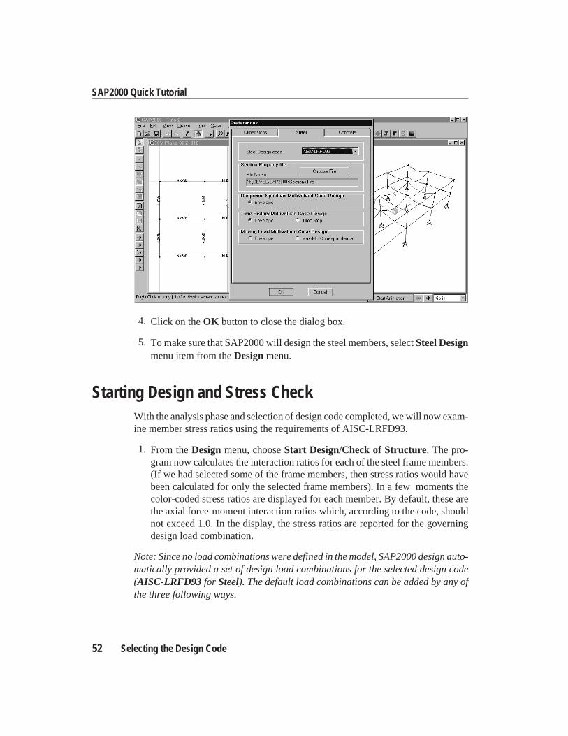
4. Click on theOK button to close the dialog box.
5. To make sure that SAP2000 will design the steel members, selectSteel Designmenu item from theDesignmenu.
Starting Design and Stress CheckWith the analysis phase and selection of design code completed, we will now exam-ine member stress ratios using the requirements of AISC-LRFD93.
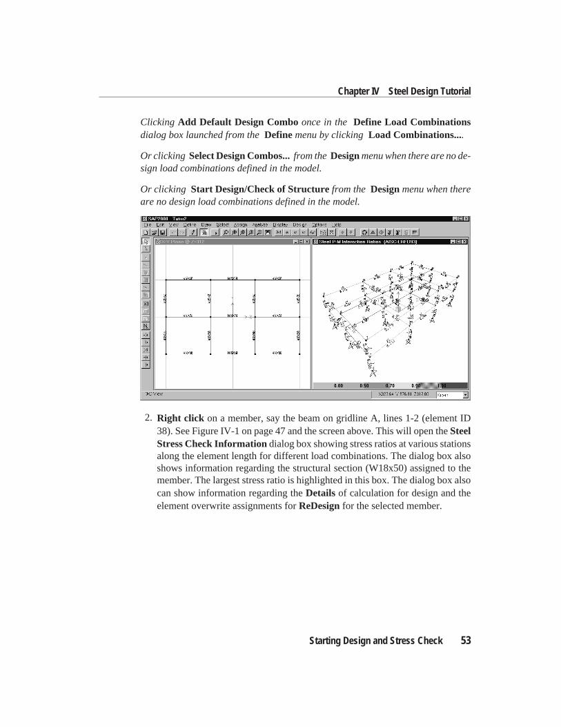
1. From theDesignmenu, chooseStart Design/Check of Structure. The pro-gram now calculates the interaction ratios for each of the steel frame members.(If we had selected some of the frame members, then stress ratios would havebeen calculated for only the selected frame members). In a few moments thecolor-coded stress ratios are displayed for each member. By default, these arethe axial force-moment interaction ratios which, according to the code, shouldnot exceed 1.0. In the display, the stress ratios are reported for the governingdesign load combination.
Note: Since no load combinations were defined in the model, SAP2000 design auto-matically provided a set of design load combinations for the selected design code(AISC-LRFD93 for Steel). The default load combinations can be added by any ofthe three following ways.
52 Selecting the Design Code
SAP2000 Quick Tutorial
Clicking Add Default Design Comboonce in the Define Load Combinationsdialog box launched from theDefinemenu by clickingLoad Combinations....
Or clicking Select Design Combos...from theDesignmenu when there are no de-sign load combinations defined in the model.
Or clicking Start Design/Check of Structurefrom the Designmenu when thereare no design load combinations defined in the model.
2. Right click on a member, say the beam on gridline A, lines 1-2 (element ID38). See Figure IV-1 on page 47 and the screen above. This will open theSteelStress Check Informationdialog box showing stress ratios at various stationsalong the element length for different load combinations. The dialog box alsoshows information regarding the structural section (W18x50) assigned to themember. The largest stress ratio is highlighted in this box. The dialog box alsocan show information regarding theDetails of calculation for design and theelement overwrite assignments forReDesignfor the selected member.
Starting Design and Stress Check 53
Chapter IV Steel Design Tutorial
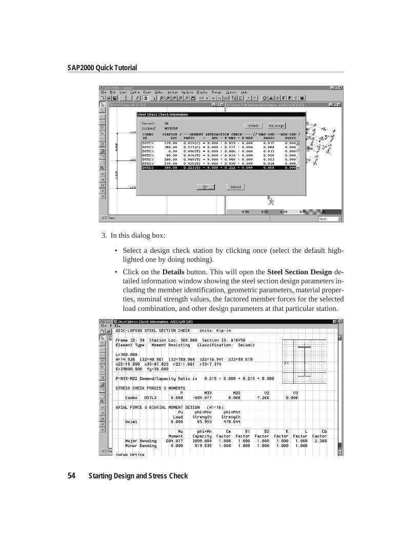
3. In this dialog box:
• Select a design check station by clicking once (select the default high-lighted one by doing nothing).
• Click on theDetails button. This will open theSteel Section Designde-tailed information window showing the steel section design parameters in-cluding the member identification, geometric parameters, material proper-ties, nominal strength values, the factored member forces for the selectedload combination, and other design parameters at that particular station.
54 Starting Design and Stress Check
SAP2000 Quick Tutorial
• Close theSteel Section Designinformation window.
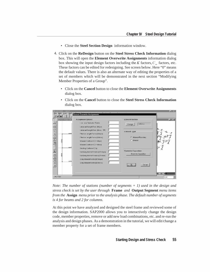
4. Click on theReDesignbutton on theSteel Stress Check Informationdialogbox. This will open theElement Overwrite Assignmentsinformation dialogbox showing the input design factors including theK factors,C
mfactors, etc.
These factors can be edited for redesigning. See screen below. Here “0” meansthe default values. There is also an alternate way of editing the properties of aset of members which will be demonstrated in the next section “ModifyingMember Properties of a Group”.
• Click on theCancelbutton to close theElement Overwrite Assignmentsdialog box.
• Click on theCancelbutton to close theSteel Stress Check Informationdialog box.
Note: The number of stations (number of segments + 1) used in the design andstress check is set by the user throughFrame and Output Segmentmenu itemsfrom theAssign menu prior to the analysis phase. The default number of segmentsis 4 for beams and 2 for columns.
At this point we have analyzed and designed the steel frame and reviewed some ofthe design information. SAP2000 allows you to interactively change the designcode, member properties, remove or add new load combinations, etc. and re-run theanalysis and design phases. As a demonstration in the tutorial, we will edit/change amember property for a set of frame members.
Starting Design and Stress Check 55
Chapter IV Steel Design Tutorial
Modifying Member PropertiesWith the analysis and stress check successfully completed, we will now modify thelateral unsupported length of all the beams and girders because the stress ratios aregreater than 1 for some of the beams and girders andl r > 200 for many of thebeams. Initially, in the design check, the unbraced length of each member wastaken to be the member full length in both the major and minor directions, i.e.l l L22 33
= = . However, the secondary beams of the floor structure provide restraintsagainst lateral displacement of the compression flange. Referring to Figure IV-1(page 47) we will take the minor direction unbraced length,l
22, of every beam span-
ning N-S (Y-Y) as 33% of the actual length. Likewise, for beams spanning E-W(X-X), l
22is assumed to be 25% of the actual length. In order to make these
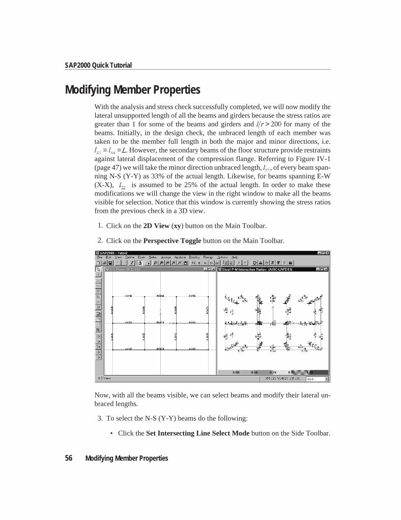
modifications we will change the view in the right window to make all the beamsvisible for selection. Notice that this window is currently showing the stress ratiosfrom the previous check in a 3D view.
1. Click on the2D View (xy) button on the Main Toolbar.
2. Click on thePerspective Togglebutton on the Main Toolbar.
Now, with all the beams visible, we can select beams and modify their lateral un-braced lengths.
3. To select the N-S (Y-Y) beams do the following:
• Click theSet Intersecting Line Select Modebutton on the Side Toolbar.
56 Modifying Member Properties
SAP2000 Quick Tutorial
• Move the pointer to the left of the beam on line 1, bay A-B.
• Click and hold down the left mouse button.
• While holding, move the pointer to the right intersecting all the beams inthe bay between lines A and B. A “rubber-band line” in the Y-Y directionwill show the intersecting line.
• Release the left mouse button to select all members that intersect this line.The message area at the bottom-left corner of SAP2000 responds by show-ing that8 Frames Selected.
Note: To select all the N-S beams we have to do this operation (Step 3)twice; once, for all the beams between lines A and B, and once for beamsspanning between lines B and C.
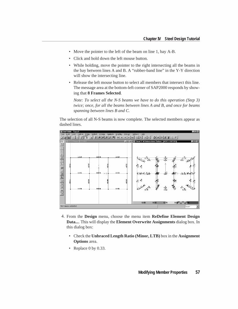
The selection of all N-S beams is now complete. The selected members appear asdashed lines.
4. From theDesign menu, choose the menu itemReDefine Element DesignData.... This will display theElement Overwrite Assignmentsdialog box. Inthis dialog box:
• Check theUnbraced Length Ratio (Minor, LTB) box in theAssignmentOptions area.
• Replace 0 by 0.33.
Modifying Member Properties 57
Chapter IV Steel Design Tutorial
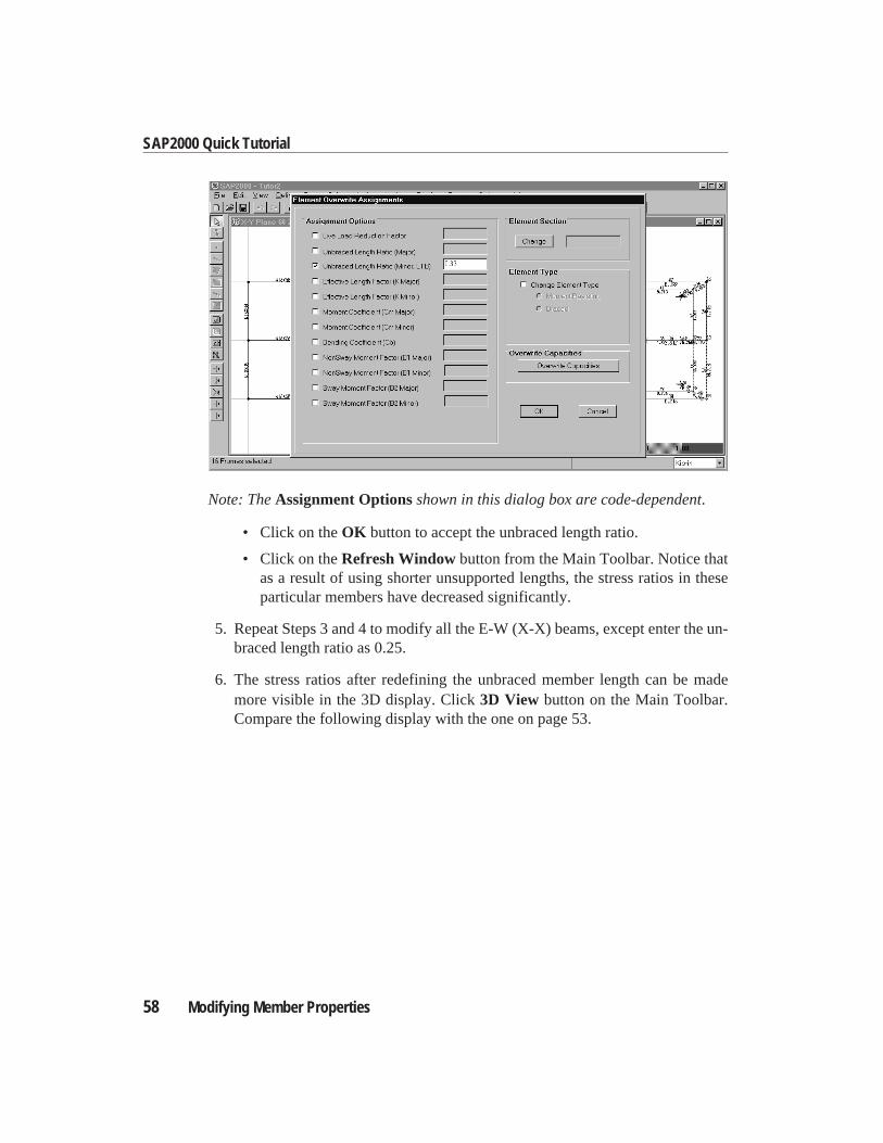
Note: TheAssignment Optionsshown in this dialog box are code-dependent.
• Click on theOK button to accept the unbraced length ratio.
• Click on theRefresh Windowbutton from the Main Toolbar. Notice thatas a result of using shorter unsupported lengths, the stress ratios in theseparticular members have decreased significantly.
5. Repeat Steps 3 and 4 to modify all the E-W (X-X) beams, except enter the un-braced length ratio as 0.25.
6. The stress ratios after redefining the unbraced member length can be mademore visible in the 3D display. Click3D View button on the Main Toolbar.Compare the following display with the one on page 53.
58 Modifying Member Properties
SAP2000 Quick Tutorial
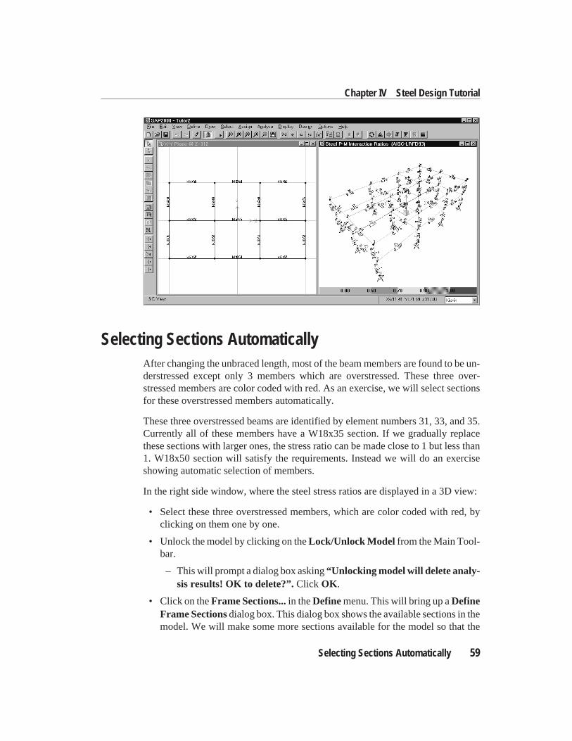
Selecting Sections AutomaticallyAfter changing the unbraced length, most of the beam members are found to be un-derstressed except only 3 members which are overstressed. These three over-stressed members are color coded with red. As an exercise, we will select sectionsfor these overstressed members automatically.
These three overstressed beams are identified by element numbers 31, 33, and 35.Currently all of these members have a W18x35 section. If we gradually replacethese sections with larger ones, the stress ratio can be made close to 1 but less than1. W18x50 section will satisfy the requirements. Instead we will do an exerciseshowing automatic selection of members.
In the right side window, where the steel stress ratios are displayed in a 3D view:
• Select these three overstressed members, which are color coded with red, byclicking on them one by one.
• Unlock the model by clicking on theLock/Unlock Model from the Main Tool-bar.
– This will prompt a dialog box asking“Unlocking model will delete analy-sis results! OK to delete?”.Click OK .
• Click on theFrame Sections...in theDefinemenu. This will bring up aDefineFrame Sectionsdialog box. This dialog box shows the available sections in themodel. We will make some more sections available for the model so that the
Selecting Sections Automatically 59
Chapter IV Steel Design Tutorial
program can choose the automatically selected section from a wider group.Since the W18x35 is too big for some members, we will add some smaller sec-tions, especially wide flange sections with 12 inch depth, for the domain ofAUTO section. To achieve this, in this dialog box:
– Click on theImport pull down arrow.
– Scroll through the sections and chooseImport I/Wide Flange . This willbring anImport I/Wide Flange section property list.
Note: In this dialog box, the default section property fileSection.proisused. This file can be re-chosen from thePreferencesform from theOp-tionsmenu.
– Scroll down through the sections and selectW12x96 by clicking. Scrolldown through the sections again and selectW12x14by holding down theShift Key and clicking. This will select all the sections ranging fromW12x96 to W12x14.
– Click OK to choose the sections just selected. The response will be a dis-play of information in theI/Wide Flange Sectionsdialog box about thelast selected section, i.e.,W12x14.
– Click OK in the I/Wide Flange Sectionsdialog box. This will completeimporting the newly selected sections into the model from the database.The imported sections are added to theFrame Sectionslist in theDefineFrame Sectionsdialog box.
– Click on theAdd pull down arrow in this dialog box.
– Scroll through the sections and chooseAdd Auto Select. This will bring anAuto Selection Sectionsdialog box. In this dialog box, the default domainof the Auto Sections is listed. You can edit the list by adding and deletingnew sections. Scroll through the sections down to W14x132 and select it byclicking. The Remove button is highlighted. Click on theRemovebuttonto remove this specific section from the domain of the auto section becausethe W14x132 is specifically used in this model for columns. The defaultname of the auto section is given as AUTO1. ClickOK to accept the de-fault name and the list of sections.
– Click theOK button to close theDefine Frame Sectionsdialog box.
• Click on theAssignmenu, select theFrame menu item, and then selectSec-tions... . This will open theDefine Frame Sectionsdialog box. In this dialogbox you selectAUTO1 and then clickOK . This will change the display recog-nizing that the selected members haveAUTO1 section.
60 Selecting Sections Automatically
SAP2000 Quick Tutorial
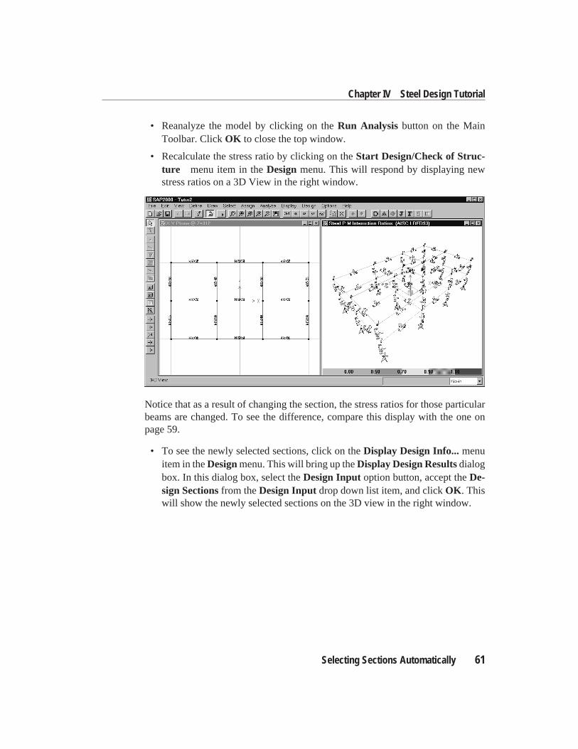
• Reanalyze the model by clicking on theRun Analysis button on the MainToolbar. ClickOK to close the top window.
• Recalculate the stress ratio by clicking on theStart Design/Check of Struc-ture menu item in theDesignmenu. This will respond by displaying newstress ratios on a 3D View in the right window.
Notice that as a result of changing the section, the stress ratios for those particularbeams are changed. To see the difference, compare this display with the one onpage 59.
• To see the newly selected sections, click on theDisplay Design Info...menuitem in theDesignmenu. This will bring up theDisplay Design Resultsdialogbox. In this dialog box, select theDesign Input option button, accept theDe-sign Sectionsfrom theDesign Input drop down list item, and clickOK . Thiswill show the newly selected sections on the 3D view in the right window.
Selecting Sections Automatically 61
Chapter IV Steel Design Tutorial
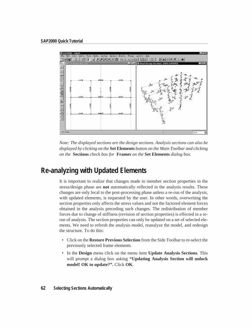
Note: The displayed sections are the design sections. Analysis sections can also bedisplayed by clicking on theSet Elementsbutton on the Main Toolbar and clickingon the Sectionscheck box forFrameson theSet Elementsdialog box.
Re-analyzing with Updated ElementsIt is important to realize that changes made to member section properties in thestress/design phase arenot automatically reflected in the analysis results. Thesechanges are only local to the post-processing phase unless a re-run of the analysis,with updated elements, is requested by the user. In other words, overwriting thesection properties only affects the stress values and not the factored element forcesobtained in the analysis preceding such changes. The redistribution of memberforces due to change of stiffness (revision of section properties) is effected in a re-run of analysis. The section properties can only be updated on a set of selected ele-ments. We need to refresh the analysis model, reanalyze the model, and redesignthe structure. To do this:
• Click on theRestore Previous Selectionfrom the Side Toolbar to re-select thepreviously selected frame elements.
• In theDesignmenu click on the menu itemUpdate Analysis Sections. Thiswill prompt a dialog box asking“Updating Analysis Section will unlockmodel! OK to update?”. Click OK .
62 Selecting Sections Automatically
SAP2000 Quick Tutorial
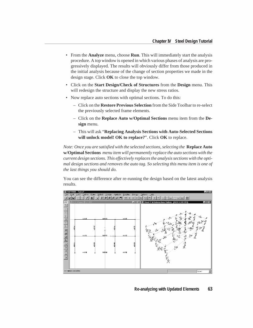
• From theAnalyzemenu, chooseRun. This will immediately start the analysisprocedure. A top window is opened in which various phases of analysis are pro-gressively displayed. The results will obviously differ from those produced inthe initial analysis because of the change of section properties we made in thedesign stage. ClickOK to close the top window.
• Click on theStart Design/Check of Structuresfrom theDesignmenu. Thiswill redesign the structure and display the new stress ratios.
• Now replace auto sections with optimal sections. To do this:
– Click on theRestore Previous Selectionfrom the Side Toolbar to re-selectthe previously selected frame elements.
– Click on theReplace Auto w/Optimal Sectionsmenu item from theDe-signmenu.
– This will ask “Replacing Analysis Sections with Auto-Selected Sectionswill unlock model! OK to replace?”. Click OK to replace.
Note: Once you are satisfied with the selected sections, selecting theReplace Autow/Optimal Sectionsmenu item will permanently replace the auto sections with thecurrent design sections. This effectively replaces the analysis sections with the opti-mal design sections and removes the auto tag. So selecting this menu item is one ofthe last things you should do.
You can see the difference after re-running the design based on the latest analysisresults.
Re-analyzing with Updated Elements 63
Chapter IV Steel Design Tutorial
Concluding RemarksWe have come to the end of this tutorial on the SAP2000 steel design options. Theintent has been to highlight and demonstrate a few of the basic features in order toopen up the path for you to explore and use the more advanced options. For more in-formation on various topics consult the on-line Help provided.
64 Concluding Remarks
SAP2000 Quick Tutorial