Embed Size (px)
Citation preview

1
Heavyweight Pullman sleepers assigned to the Santa Fe were
unique in several ways, all due to the application of steam
ejector air conditioning systems during the 1930s. The distinc-
tive roof hatches and underneath equipment provide great
modeling opportunities, but it takes more than adding those
details to a generic plastic or brass Pullman if you want a truly
accurate Santa Fe model.
It’s all in the ducts
On most AC installations, the air conditioner unit is mounted
within the clerestory at the end of the car over the lavatory,
and make-up air is drawn through the vestibule ceiling. The
compressor (for mechanical or electromechanical systems) or
ice boxes (for ice AC systems) that provide chilled fluid to the
air conditioner are mounted under the car. The ends of the
external ducts that deliver conditioned air to the car are in line,
and adjacent to the air conditioner unit as shown in Figure 1.
In roof-mounted steam ejector installations, the steam ejector
unit is at the end of the clerestory and the air conditioner is
inboard of that. The ducts begin further inboard as well. With
the AC unit now well away from the vestibule, make-up air is
drawn through the clerestory wall. To make room for the
make-up air intakes, the end of the duct on that side may be
offset from the duct on the other side, as shown in Figure 2.
Topeka - the City Different
There were more differences in the ducts than location. Some
of the installations were done by Pullman at their Calumet,
Illinois Shops, but most were done by the Santa Fe at their
Topeka Shops. Calumet installations featured smoothly curved
ducts with tapered ends constructed from overlapping plates.
Topeka installations featured ducts with straight outer walls
and formed ends.
Air conditioning timeline
The first Santa Fe-assigned Pullmans with steam ejector air
conditioning came out of the shops in 1934. Calumet delivered
six 3-2 and three 10-Section observation sleepers, while
Topeka delivered eight 3-2 observation sleepers and 13 6-3 all
room sleepers. In addition, Topeka air conditioned 36 Santa
Fe-owned cars: 14 diners, ten lounges, eight club cars and four
café-observations.
In 1935, 195 Pullmans and 78 Santa Fe cars joined the air
conditioned fleet. Calumet delivered 28 16-Section tourist cars
and 23 single vestibule 10-1-2 sleepers, while Topeka out-
shopped 31 12-1 sleepers (most of which became 14-Section
tourist cars), nine 14-Section tourist cars (all of which were
former 12-1s), 23 10-2 sleepers, 20 two vestibule 10-1-2 sleep-
ers, eight 10-Section observation sleepers, ten 10-Section
lounges, two 6-3 sleepers, two 7 Drawing Room sleepers, 28
8-1-2 sleepers, seven 14-Section sleepers (the “Famous Men”
series, not to be confused with the 14-Section tourist cars) and
four 16-Section tourist cars. Plus the 78 Santa Fe cars!
In 1936/37 Calumet outshopped eight 10-2 sleepers, while
Topeka delivered seven 10-2s and 17 16-Section tourist cars.
In 1940 seven previously air conditioned 10-2s emerged from
Calumet as 6-1-4 sleepers with streamstyled turtle roofs - the
legendary TRIBE cars.
Appendix I lists all 257 Pullmans sorted by Plan number.
Body style and generator data are also listed. The seven
TRIBEs are listed separately and in addition to the 257, as they
were major rebuilds of the predecessor cars.
Modeling Santa Fe Assigned Heavyweight Pullmans
Part 1: The Prototypes
by Tom Madden
Pullman BISON PEAK, Orange Empire Railway Museum, author’s photo
Figure 1
Figure 2
Calumet Topeka
2
How does the dang thing work?
How do you get cold air from steam? It’s all in the physics.
Think of it as an airbrush on steroids connected to a vacuum
chamber where low temperature boiling of water takes place,
with a touch of evaporative cooling (swamp cooling) tossed in
for good measure.
Trainline steam passes through a steam control box to reduce
the pressure and remove excess water. The steam is then
ejected through a nozzle (that’s the airbrush part), and when it
expands coming out of the nozzle it creates a vacuum. That’s
known as the “Venturi Effect”, and it’s what makes an
airbrush work. An airbrush doesn't “suck” the paint out of the
bottle, just as you don’t actually “suck” fluid out of a glass
through a straw. You draw the air from the straw, creating a
vacuum, and the air pressure on the liquid in the glass pushes
it up the straw. Same with the airbrush. There’s a hole in the
lid of the paint jar to let air in, so when you create a vacuum in
the airbrush tip, the atmospheric pressure on the paint in the jar
pushes the paint up the tube into the nozzle area, where the
expanding jet of air breaks it into tiny droplets and carries it
out the tip.
The steam ejector is like that, only the “paint jar” chamber has
no hole. With no way for air to get in, the vacuum created in
the ejector nozzle draws the air out of the chamber so it will
also be under vacuum. The chamber is called an evaporator,
and that’s where low temperature boiling takes place.
Those of us living in the Mountain time zone are familiar with
the saying, “You can’t boil an egg in Leadville”. Well, you can
certainly boil one, but because the reduced air pressure at
Leadville’s 10,000 foot elevation lowers the boiling point of
water to 194° F, you will have difficulty cooking one. If you
reduce the air pressure far enough, the boiling point can be
reduced to well below room temperature. A steam ejector
system maintains a vacuum of 29.88” of mercury in the
evaporator, and the boiling point of water at that reduced
pressure is 50° F.
Now comes the physics part. Water will boil if the boiling
point is lower than the temperature of the water. But it takes
energy to change the “phase” of the water from liquid to gas.
In normal boiling we add that energy externally, in the form of
heat from a gas flame or electric heater. But if there is no
external energy source, the needed energy is extracted from
the heat stored in the water itself. Remove heat from warm
water, and you get - Ta Da! Cold water! The boiling due to
heat removal will continue until the water cools to the boiling
point, so by maintaining the vacuum at 29.88” of mercury a
steam ejector system maintains a constant supply of 50°
chilled water. It’s a remarkably efficient process.
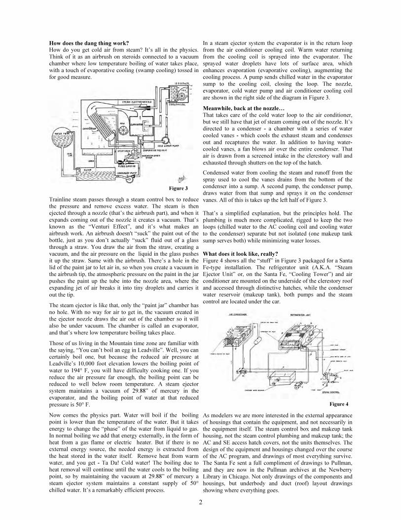
In a steam ejector system the evaporator is in the return loop
from the air conditioner cooling coil. Warm water returning
from the cooling coil is sprayed into the evaporator. The
sprayed water droplets have lots of surface area, which
enhances evaporation (evaporative cooling), augmenting the
cooling process. A pump sends chilled water in the evaporator
sump to the cooling coil, closing the loop. The nozzle,
evaporator, cold water pump and air conditioner cooling coil
are shown in the right side of the diagram in Figure 3.
Meanwhile, back at the nozzle…
That takes care of the cold water loop to the air conditioner,
but we still have that jet of steam coming out of the nozzle. It’s
directed to a condenser - a chamber with a series of water
cooled vanes - which cools the exhaust steam and condenses
out and recaptures the water. In addition to having water-
cooled vanes, a fan blows air over the entire condenser. That
air is drawn from a screened intake in the clerestory wall and
exhausted through shutters on the top of the hatch.
Condensed water from cooling the steam and runoff from the
spray used to cool the vanes drains from the bottom of the
condenser into a sump. A second pump, the condenser pump,
draws water from that sump and sprays it on the condenser
vanes. All of this is takes up the left half of Figure 3.
That’s a simplified explanation, but the principles hold. The
plumbing is much more complicated, rigged to keep the two
loops (chilled water to the AC cooling coil and cooling water
to the condenser) separate but not isolated (one makeup tank
sump serves both) while minimizing water losses.
What does it look like, really?
Figure 4 shows all the “stuff” in Figure 3 packaged for a Santa
Fe-type installation. The refrigerator unit (A.K.A. “Steam
Ejector Unit” or, on the Santa Fe, “Cooling Tower”) and air
conditioner are mounted on the underside of the clerestory roof
and accessed through distinctive hatches, while the condenser
water reservoir (makeup tank), both pumps and the steam
control are located under the car.
As modelers we are more interested in the external appearance
of housings that contain the equipment, and not necessarily in
the equipment itself. The steam control box and makeup tank
housing, not the steam control plumbing and makeup tank; the
AC and SE access hatch covers, not the units themselves. The
design of the equipment and housings changed over the course
of the AC program, and drawings of most everything survive.
The Santa Fe sent a full compliment of drawings to Pullman,
and they are now in the Pullman archives at the Newberry
Library in Chicago. Not only drawings of the components and
housings, but underbody and duct (roof) layout drawings
showing where everything goes.
Figure 3
Figure 4

3
Equipment I - hatch covers
From 1934 through 1936 five air conditioner and three steam
ejector hatch designs were employed. SE and AC units were
installed over non-revenue space, so cars with smaller lavato-
ries were equipped with smaller AC units and shorter hatches.
Figure 5 shows the five AC hatches. Hatch 1934 “B” was
used on only three cars, 10 section observations Mts. TAY-
LOR, KING and BRECKENRIDGE. All the other 1934 instal-
lations were on all-room Pullmans with ducts on one side of
the clerestory. For those applications the AC unit was mounted
crosswise, since it did not have to deliver air to ducts on both
sides of the clerestory.
The three 1935/36 AC hatches were all applied to section
sleepers with ducts on both sides of the clerestory. All were
the same width and featured the same access hatches, but var-
ied in length to match the sizes of the AC units under them.
Figure 6 shows the three steam ejector hatch designs. All were
the same size, but with some variation in shutter position and
access hatch size.
Equipment II - hatch locations
The SE and AC units were placed next to each other over the
men's lavatory whenever possible, but sometimes the layout of
revenue space didn’t permit that. The top drawing in Figure 7
shows the most common layout on a section sleeper with a
large men’s lavatory. The 10-2 in the middle drawing has a
very small men’s lavatory, and the AC unit was located over a
drawing room annex (toilet). The 3523C 6-3, bottom, was an
all-room car with no men’s lavatory. The SE unit was placed
over two back-to-back drawing room annexes in the middle of
the car and the AC unit over another annex at the car end.
Equipment III - clerestory air intakes
Both the SE and AC units drew air through openings in the
clerestory wall, and those openings were fitted with a variety
of intake filters and housings. Air to cool the steam ejector
condenser was always drawn from the side opposite the hatch
shutters, but makeup air for the air conditioner could be drawn
from either side, or from both sides.
The photo below shows a large intake housing for the SE unit
and a small hooded filter housing for the AC unit.
The next photo shows a large hooded filter housing for the AC
unit. Duct drawings for these two AC hooded filter designs
show that the openings in the clerestory walls were the same
size, but the larger housing contained a much larger filter,
which presumably required less frequent changing.
The third photo shows a pair of AC intake filters with no hood,
a 1934 installation on a 3523C 6-3. The car on the right,
GLEN ROBERTS, is also a 6-3 and shows the opposite side of
the same (AC) end of the car.
A few words about equipment boxes
Generally, Pullman equipment box covers were not hinged.
Large covers were nested into cleats riveted to the bottom of
the housing and retained by hasps and pins, while smaller ones
were retained by wing nuts and washers on threaded studs.
Pullman did nothing for no reason, so this was presumably a
safer and more durable arrangement. If the fastenings failed a
cover would fall onto the ROW instead of banging against the
rails, and servicing personnel had to lift large covers out of the
cleats and set them aside instead of pulling the pins and letting
them drop. (The cords in the photos below anchor a tarpaulin
protecting a museum-stored car.)
1935 19361934
Figure 6
Figure 5
1935/36"A" 1935/36 "B" 1935/36 "C"
1934 "A" 1934 "B"
Plan 3410A 12-1
Plan 3584 10-2
Plan 3523C 6-3
Figure 7

4
Figure 8
Figure 9
Equipment IV - steam control box
The functional parts of the steam control unit are shown in
Figure 8. Two pressure reducing valves in a duplex arrange-
ment provided redundancy. Only one was in use at a time with
the other isolated by shutoff valves. It could be configured for
either left- or right-handed operation.
Figure 9 shows right-handed versions of all the steam control
boxes.
Like the hatches, the design of the steam control boxes
changed over the years. The 1934 units had a one-piece cover
and the steam inlet on the back. The 1935 and 1936 designs
had the steam inlets on the ends, and separate covers for the
motor operated valve and the pressure reducing valve compart-
ments. Both changes simplified servicing the units. In 1936 the
pin and hasp location was lowered from the top to the center of
the box. See Appendix II for application information.
Equipment V - makeup tank and condenser pump
These units also changed over the installation period, although
all were “right-handed” based on the condenser pump location.
Figure 10 shows the various versions. The 1934 makeup tank
drawing is missing from both the Newberry and Temple, TX
collections. Figure 10 includes a 3D CAD design of the 1934
makeup tank applied to Plan 3523C 6-3 Pullmans, interpolated
from a photo of the tank on GLEN ROBERTS and the Santa
Fe underneath equipment drawing showing the tank’s foot-
print.
Equipment VI - cold water pump
The 1934 cold water pump was located in the makeup tank
housing. The pump body is visible high on the left side of the
1934 makeup tank shown in Figure 10. For 1935 and 1936
installations the CW pump was amounted separately.
Santa Fe drawing 23-A-2484 (2/9/1935) shows an unprotected
cold water pump, while drawing 23-A-2646 (3/7/1936) shows
the pump encased in a small housing. This infers that 1935
installations had unprotected CW pumps, while 1936 and later
ones were encased. Postwar photos show encased CW pumps
on all post-1934 installations. One presumes the unprotected
pumps would have been prone to damage and were later en-
cased. Figure 11 shows both versions. Like the steam control
boxes, the encased pumps were installed in both left- and
right-handed configurations. See Appendix II for application
information.
Equipment VII - generators
Santa Fe-assigned Pullmans were equipped with 4 KW light-
ing generators, either #2 body mounted or #5 truck mounted.
A second 4 KW generator was installed when a car was air
conditioned, and these were also a mix of body and truck
mountings. In the mid 1940s three Plan 3523C cars received
10 KW generators, possibly replacing both 4 KW generators.
With one possible exception, all cars with top equalized 242 or
242A trucks received two body mounted generators. Pullman’s
records show Tourist Car 4166 with 242 trucks and truck
mounted generators. It may be a clerical error. The majority of
cars with bottom equalized 1910, 1910A, 2410, 2410A or
2411 trucks received two truck mounted generators, although
five had two body mounted generators and 52 had one of each
type. See Appendix I for each car’s generator schedule. An
asterisk indicates a car had one of each type but the end of the
car each went on is not specified.
Pullman body construction variations
The evolution of Pullman’s construction practices resulted in
three different body styles for Santa Fe-assigned heavyweight
Pullmans, each related to the time they were built. The earliest
steel Pullmans (1910-1916) were styled to match the wood
cars of the era and featured “grooved” steel siding, actually
interlocking strips of formed sheet steel, and decorative leaded
glass upper transoms (“Gothics”) over each window. All were
built with curved-top ends. Collectively these are known as
Gothic cars. Pullman introduced riveted steel plate side con-
struction in 1916 but stayed with the same car length, 73’-6”
over end sills, and curved-top ends. These were Intermediate
cars. In 1923 Pullman added a foot to the basic car length,
changed Plan numbers from 2xxx to 3xxx, and introduced the
“pedimented” (flat-topped) car end. These Late cars also had
1934
1935
1936
Figure 11 1936 1935
Truck Mounted Body Mounted
1934
1935
1936
Figure 10

5
redesigned belt rails with fasteners in both the upper and lower
sections. Except for the belt rail differences, the Intermediate
and Late side rivet patterns were identical - six rivets in each
vertical row in the lower side sheets, no rivet row under the
center post in paired windows, and single pairs of rivets in the
letterboard in line with the rows in the lower side sheets.
In 1917 Pullman began rebuilding Gothic cars, adding steel
plate lower side sheets and wide letterboards that covered the
Gothics. The rivet pattern on these Rebuilt Gothic cars had
four rivets in each vertical row in the lower side sheets, an
identical row under the center post of each paired window, and
double pairs of rivets in the letterboards. Paired window center
posts on Rebuilt Gothic cars had a double rivet pattern, while
the Intermediate and Late paired windows had narrower center
posts with single rows of rivets. No Gothic cars were air con-
ditioned (few survived as-built past the mid-1930s), but many
Rebuilt Gothics were. Figure 12 shows the rivet patterns for
Intermediate, Late and Rebuilt Gothic paired windows.
Gothic cars rebuilt prior to 1923 kept their curved-top ends,
while those rebuilt after 1923 were fitted with pedimented
ends. The photos below show examples of curved-top and
pedimented ends.
Appendix I lists the rivet pattern and end type for each Santa
Fe Pullman. The end types for Rebuilt Gothic cars are inferred
from the date each was rebuilt, with the three 1923 rebuilds
listed as “Uncertain”. If a pre-1923 Rebuilt Gothic car with
curved-top ends suffered damage after 1923 and needed new
ends, it would have gotten pedimented ends. Photos are your
only guide for those. Photos always trump inferred data, since
Pullman’s record keeping was not error-free.
Timeline considerations
Santa Fe’s fleet of heavyweight Pullmans dwindled over time.
Of the 257 Pullmans air conditioned for the Santa Fe from
1934 through 1937, 130 named cars were still assigned to the
road on December 31, 1945. The Santa Fe took ownership of
71 of them on December 31, 1948 as part of the Pullman anti-
trust divestiture agreement, and declined the rest. Tourist cars
were excluded. Accepted were the seven 3958 “Famous Men”
14-Section sleepers, ten 3521C GENERAL 10-Section
lounges, seven 3523C and two 3523E 6-3 sleepers, ten 3585E
LAKE suffix 10-1-2s, 28 3979A CENT 8-1-2s, and seven
4092 TRIBE cars. All the declined sleepers and excluded
Tourist cars remained under Pullman ownership, and some of
those declined sleepers continued their Santa Fe assignments.
Many of the tourist cars were renumbered and had their air
conditioning systems deactivated in 1950-51 for Korean war
service. These post-ATSF service changes are not shown in
Appendix I. Between November 1952 and February 1953 the
Santa Fe repurposed its 3521C GENERAL 10-Section
lounges as coaches, numbering them 1155 through 1164. In
May and June 1953 the Santa Fe purchased from Pullman 16
previously declined steam ejector-equipped 10-2 sleepers and
used them as coaches, numbering them 1126 through 1141.
Paint schemes
All heavyweight sleepers wore Pullman’s standard Pullman
green paint scheme when they were air conditioned. Tourist
cars assigned to the Scout were refurbished and painted light-
dark-light two tone gray in 1940 and featured a distinctive
Scout name plate centered on the lower side sheets. Use of
these cars in Scout service decreased dramatically after the
war. Those that had their air conditioning deactivated were
repainted Pullman green. The others whiled away their final
years in storage in fading two tone gray. All were ultimately
scrapped or sold to individual railroads for company service
use. The Santa Fe bought seven.
In June 1949 COMANCHE TRIBE received the short-lived
shadowline paint scheme. In 1951 and 1952 it and the other six
TRIBE cars were repainted two tone gray with SANTA FE on
the letterboard. In 1957 8-1-2s CENTASH, CENTROCK and
CENTWELL were repainted with the same scheme. All others
remained Pullman green with PULLMAN on the letterboard.
Part 2 will cover modeling opportunities for these interesting
cars.
Intermediate Late Rebuilt Gothic
Figure 12
Curved-top End Pedimented End
KIOWA TRIBE, Dean Hale photo, author’s collection
GLEN ROBERTS, Bob’s Photos
Author’s photos

Appendix 1
Santa Fe-Assigned Pullmans with
Steam Ejector Air Conditioning
Name Plan AC Location Trucks AC Date Left (Mens end) Gen.
Right (Womens end) Gen.
Ends Rivet Pattern
Notes
Prometheus 2410 Topeka 1910A 11-Sep-35 #5 #5 Ped RG To Plan 4061 TC 3045Vandor 2410 Topeka 1910A 12-Sep-35 * * Ped RG To Plan 4061 TC 3046Bushard 2410A Topeka 1910A 24-Aug-35 #5 #5 Uncertain RG To Plan 4061 TC 3040Chatsworth 2410A Topeka 1910A 7-Jun-35 #5 #5 Ped RG To Plan 4061 TC 3041Fort Monroe 2410A Topeka 1910A 29-Aug-35 * * Ped RG To Plan 4061 TC 3077Orston 2410A Topeka 1910A 1-Jun-35 * * Ped RG To Plan 4061 TC 3043Parvin 2410A Topeka 1910A 5-Sep-35 #2 #5 Cur RG To Plan 4061 TC 3044Aylesbury 2410B Topeka 242 13-Sep-35 #2 #2 Cur RG To Plan 4061 TC 3038Isolita 2410B Topeka 2410A 17-May-35 #5 #5 Ped RG To Plan 4061 TC 3042Alpland 2410E Topeka 1910A 20-Aug-35 #5 #5 Ped RG To Plan 4061 TC 3078Burland 2410F Topeka 1910A 12-Jun-35 #5 #5 Cur Int To Plan 4061 TC 3039Bohemian 2410I Topeka 1910A 24-May-35 #5 ? Ped RG To Plan 4061A TC 3098Bonsecour 2410I Topeka 1910A 21-May-35 #5 #5 Ped RG To Plan 4061A TC 3099Elveden 2410I Topeka 1910A 18-May-35 #5 #5 Ped RG To Plan 4061A TC 3101Holtenau 2410I Topeka 1910A 4-Jun-35 #5 #5 Ped RG To Plan 4061A TC 3103Islesboro 2410I Topeka 1910A 27-May-35 #5 #5 Ped RG To Plan 4061A TC 3102Milbank 2410I Topeka 1910A 6-Jun-35 #5 #5 Ped RG To Plan 4061A TC 3105Napanoch 2410I Topeka 1910A 1-Jun-35 #5 #5 Ped RG To Plan 4061B TC 3108Oakhill 2410I Topeka 1910A 3-Aug-35 #5 #5 Ped RG To Plan 4061A TC 3100Ondawa 2410I Topeka 1910A 1-May-35 #5 #5 Ped RG To Plan 4061A TC 3106Raritan 2410I Topeka 1910A 6-Jun-35 #5 #5 Ped RG To Plan 4061A TC 3104Sebago 2410I Topeka 1910A 27-May-35 #5 #5 Ped RG To Plan 4061B TC 3107Sundridge 2410I Topeka 1910A 8-Aug-35 #5 #5 Ped RG To Plan 4061B TC 3109TC 4165 2412 Topeka 2410A 4-May-36 #2 #2 Cur RG From Plan 2412 Belvidere
TC 4166 2412 Topeka 242 27-Apr-36 #5 #5 Uncertain RG From Plan 2412 Bethalto
TC 4168 2412 Topeka 1910A 1-May-36 #2 #2 Ped RG From Plan 2412 Greystone
TC 4170 2412A Topeka 1910A 8-May-36 #5 #5 Cur RG From Plan 2412A Galeton
TC 4173 2412A Topeka 1910A 6-May-36 #5 #5 Ped RG From Plan 2412A Honeoye
TC 4175 2412B Topeka 1910A 15-Apr-36 #5 #5 Ped RG From Plan 2412B Serapis
TC 4191 2412B Topeka 1910A 13-May-36 #5 #5 Cur RG From Plan 2412B Malabar
Eclipse 2412C Topeka 1910A 18-May-35 #5 #5 Ped RG To Plan 2412W TC 4224
Emrytra 2412C Topeka 1910A 4-Jun-35 * * Ped RG To Plan 2412W TC 4223
Kinderhook 2412C Topeka 1910 18-May-35 #5 #5 Ped RG To Plan 2412W TC 4225
Niscuba 2412C Topeka 1910A 31-May-35 #5 #5 Ped RG To Plan 2412W TC 4226
TC 4178 2412C Topeka 1910A 17-Apr-36 #5 #5 Ped RG From Plan 2412C Mayita
Generator legend: #2 - body mounted #5 - truck mounted * - one of each type, ends not specified A-1

Appendix 1
Santa Fe-Assigned Pullmans with
Steam Ejector Air Conditioning
Name Plan AC Location Trucks AC Date Left (Mens end) Gen.
Right (Womens end) Gen.
Ends Rivet Pattern
Notes
TC 4180 2412C Topeka 1910A 29-Apr-36 #2 #2 Cur RG From Plan 2412C Senachwine
TC 4161 2412F Topeka 1910A 24-Apr-36 #5 #5 Cur Int From Plan 2412F Oxnard
TC 4164 2412F Topeka 1910A 11-May-36 #5 #5 Cur Int From Plan 2412F Cadiz
TC 4186 2412F Topeka 2410A 14-May-36 #5 #5 Cur Int From Plan 2412F Cortez
TC 4188 2412F Topeka 2410A 24-Apr-36 #5 #5 Cur Int From Plan 2412F Riverdale
TC 4193 2412F Topeka 1910A 4-May-36 #5 #5 Cur Int From Plan 2412F Bridgehill
TC 4073 2412V Calumet 1910A 19-Apr-35 #5 #5 Ped RG From Plan 2412A Maiden Rock
TC 4074 2412V Calumet 1910A 22-Apr-35 #5 #5 Cur RG From Plan 2412A Broadmoor
TC 4079 2412V Calumet 1910A 3-Apr-35 #5 #5 Cur RG From Plan 2412 Greenway
TC 4082 2412V Calumet 1910A 10-May-35 #5 #5 Ped RG From Plan 2412 Haverstraw
TC 4087 2412V Calumet 1910A 6-May-35 #5 #5 Ped RG From Plan 2412A Latimer
TC 4088 2412V Calumet 1910A 7-May-35 #5 #2 Ped RG From Plan 2412A Bridger
TC 4089 2412V Calumet 1910A 11-Apr-35 #5 #5 Cur RG From Plan 2412A Marydel
TC 4094 2412V Calumet 1910A 2-May-35 #5 #2 Cur RG From Plan 2412 Fairchance
TC 4095 2412V Calumet 1910A 3-May-35 #5 #5 Cur RG From Plan 2412 Wandin
TC 4097 2412V Calumet 1910A 9-May-35 #5 #5 Cur RG From Plan 2412A Fosston
TC 4144 2412V Calumet 1910A 19-Jul-35 #5 #5 Cur RG From Plan 2412A Bushnell
TC 4227 2412V Topeka 1910A 20-Mar-37 #5 #5 Ped RG From Plan 2412A Platanus
TC 4075 2412W Calumet 1910A 24-Apr-35 #5 #5 Ped RG From Plan 2412B Elberon
TC 4076 2412W Calumet 1910A 23-Apr-35 #5 #5 Ped RG From Plan 2412B Cynwyd
TC 4077 2412W Calumet 1910A 5-Apr-35 #5 #5 Uncertain RG From Plan 2412B Brumley
TC 4078 2412W Calumet 1910A 9-Apr-35 #5 #5 Cur RG From Plan 2412C Glasby
TC 4080 2412W Calumet 1910A 16-Apr-35 #5 #5 Cur Int From Plan 2412F Ventura
TC 4081 2412W Calumet 1910A 30-Apr-35 #5 #2 Cur Int From Plan 2412F Turner
TC 4083 2412W Calumet 1910A 28-Mar-35 #5 #5 Cur Int From Plan 2412F Tancred
TC 4084 2412W Calumet 1910A 2-May-35 #5 #2 Cur Int From 2412F Rupert; #2 applied Mens end 5/6/44
TC 4085 2412W Calumet 1910A 10-May-35 #5 #5 Cur Int From Plan 2412F Pearsall
TC 4086 2412W Calumet 1910A 18-Apr-35 #5 #5 Cur Int From Plan 2412F Hadlock
TC 4090 2412W Calumet 1910A 8-May-35 * * Cur Int From Plan 2412F Curzon
TC 4091 2412W Calumet 1910A 13-May-35 * * Cur Int From Plan 2412F Cumming
TC 4092 2412W Calumet 1910A 26-Apr-35 * * Cur Int From Plan 2412F Calgary
TC 4093 2412W Calumet 1910A 30-Apr-35 #5 #2 Cur Int From Plan 2412F Bentalon
TC 4096 2412W Calumet 1910A 7-May-35 #5 #5 Ped RG From Plan 2412B Oakmont
TC 4142 2412W Calumet 1910A 9-Jul-35 #5 #5 Cur RG From Plan 2412B Beaumoris
Generator legend: #2 - body mounted #5 - truck mounted * - one of each type, ends not specified A-2

Appendix 1
Santa Fe-Assigned Pullmans with
Steam Ejector Air Conditioning
Name Plan AC Location Trucks AC Date Left (Mens end) Gen.
Right (Womens end) Gen.
Ends Rivet Pattern
Notes
TC 4143 2412W Calumet 1910A 16-Jul-35 #2 #5 Cur Int From Plan 2412F Brinklow
TC 4179 2412W Topeka 1910A 7-May-36 #5 #5 Cur RG From Plan 2412C Nineskha
TC 4228 2412W Topeka 2410A 10-Mar-37 #5 #5 Cur Int From Plan 2412F Tybee
Montcalm 2521G Topeka 1910A 8-Jun-35 * * Ped RG 10 KW 8/23/44
Calzona 2585D Topeka 1910A 27-Aug-35 * * Ped RG
Chanute 2585D Topeka 1910A 21-May-35 #5 #5 Ped RG One 2 pt susp
Cheraw 2585D Topeka 1910A 21-Sep-35 #5 #5 Ped RG
Escalon 2585D Topeka 1910A 20-Sep-35 #5 #5 Ped RG 242 trucks 6/18/41; Mens end replaced with #2 6/18/41
Lecompton 2585D Topeka 1910A 17-May-35 #2 #2 Ped RG 242 trucks 7/23/41
Ludlow 2585D Topeka 1910A 23-May-35 #5 #5 Ped RG
Ochelata 2585D Topeka 1910A 25-May-35 #5 #5 Ped RG Changed to #2s 9/2/41
Paquita 2585D Topeka 1910A 28-May-35 #5 #5 Ped RG
Pedernal 2585D Topeka 1910A 20-Sep-35 #5 #5 Ped RG One replaced with a #2 3/11/41
Portales 2585D Topeka 1910A 10-Sep-35 #2 ? Ped RG Only one gen specified
Sparks 2585D Topeka 1910A 18-Sep-35 #5 #5 Ped RG
Sublette 2585D Topeka 1910A 23-May-35 #5 #5 Ped RG
Wildomar 2585D Topeka 1910A 17-Sep-35 #5 ? Ped RG Only one gen specified
East Byars 3410 Topeka 242A 12-Apr-35 #2 #2 Ped Late
East Cairo 3410 Topeka 242A 12-Apr-35 #2 #2 Ped Late
McCallum 3410 Topeka 242A 20-Apr-35 #2 #2 Ped Late
McCloskey 3410 Topeka 242A 22-Apr-35 #2 #2 Ped Late
McConaughy 3410 Topeka 242A 3-May-35 #2 #2 Ped Late
McConnico 3410 Topeka 242A 8-May-35 #2 #2 Ped Late
McDowell 3410 Topeka 242 2-May-35 #2 #2 Ped Late To Plan 4061C TC 3110
McKell 3410 Topeka 242A 30-Apr-35 #2 #2 Ped Late
McMann 3410 Topeka 242 4-May-35 #2 #2 Ped Late To Plan 4061C TC 3111
McPeek 3410 Topeka 242A 26-Apr-35 #2 #2 Ped Late To Plan 4061C TC 3112
McRaney 3410 Topeka 242A 25-Apr-35 #2 #2 Ped Late To Plan 4061C TC 3113
McWade 3410 Topeka 242A 2-May-35 #2 #2 Ped Late
Red Juniper 3410A Topeka 242A 20-Apr-35 #2 #2 Ped Late To Plan 4061C TC 3114
Red Mill 3410A Topeka 242A 25-Apr-35 #2 #2 Ped Late To Plan 4061C TC 3115
Red Oak 3410A Topeka 242A 29-Apr-35 #2 #2 Ped Late To Plan 4061C TC 3116
Red Pheasant 3410A Topeka 242A 19-Apr-35 #2 #2 Ped Late
Red Pine 3410A Topeka 242A 24-Apr-35 #2 #2 Ped Late To Plan 4061C TC 3117
Generator legend: #2 - body mounted #5 - truck mounted * - one of each type, ends not specified A-3

Appendix 1
Santa Fe-Assigned Pullmans with
Steam Ejector Air Conditioning
Name Plan AC Location Trucks AC Date Left (Mens end) Gen.
Right (Womens end) Gen.
Ends Rivet Pattern
Notes
Capitol Heights 3521A Topeka 242A 6-May-35 #2 #2 Ped Late
Capitol Park 3521A Topeka 242A 28-May-35 #2 #2 Ped Late
Monte Cristo 3521A Topeka 242A 4-May-35 #2 #2 Ped Late
Mt. Bolivar 3521A Topeka 2410A 27-Apr-35 #5 ? Ped Late Only one gen specified
Mt. Breckenridge 3521A Calumet 2410A 18-May-34 * * Ped Late
Mt. Chauvenet 3521A Topeka 2410A 7-May-35 #5 #5 Ped Late
Mt. Hilgard 3521A Topeka 2410A 24-May-35 #5 #5 Ped Late
Mt. King 3521A Calumet 2410A 23-May-34 * * Ped Late
Mt. Ord 3521A Topeka 2410A 23-May-35 * * Ped Late
Mt. Taylor 3521A Calumet 2410A 25-May-34 * * Ped Late
General Carr 3521C Topeka 2411 5-Mar-35 #5 #5 Ped Late
General Chaffee 3521C Topeka 2411 4-Apr-35 #5 #5 Ped Late
General Crook 3521C Topeka 2411 9-Mar-35 #5 #5 Ped Late
General Hancock 3521C Topeka 2411 17-Apr-35 #5 #5 Ped Late
General Howard 3521C Topeka 2411 3-Apr-35 #5 #5 Ped Late
General Kearny 3521C Topeka 2411 4-Mar-35 #5 #5 Ped Late
General Lawton 3521C Topeka 2411 27-Apr-35 #5 #5 Ped Late
General Mills 3521C Topeka 2411 27-Apr-35 #5 #5 Ped Late
General Schofield 3521C Topeka 2411 16-Feb-35 #5 #5 Ped Late
General Stoneman 3521C Topeka 2411 2-Mar-35 #5 #5 Ped Late
Glen Beach 3523C Topeka 2411 18-Jun-34 #5 #2 Ped Late
Glen Crest 3523C Topeka 2411 21-Jun-34 #5 #2 Ped Late 10 KW 4/26/46
Glen Delta 3523C Topeka 2411 28-May-34 #5 #2 Ped Late
Glen Ewen 3523C Topeka 2411 15-May-34 #5 #2 Ped Late
Glen Forge 3523C Topeka 2411 11-Jun-34 #5 #2 Ped Late
Glen Frazer 3523C Topeka 2411 11-May-34 #5 #5 Ped Late
Glen Irwin 3523C Topeka 2411 19-May-34 #5 #5 Ped Late
Glen Karn 3523C Topeka 2411 8-May-34 #5 #5 Ped Late
Glen Norman 3523C Topeka 2411 6-Jun-34 #5 #5 Ped Late
Glen Pool 3523C Topeka 2411 12-May-34 #5 #2 Ped Late 10 KW body hung 1/24/46
Glen Rio 3523C Topeka 2411 28-May-34 #5 #2 Ped Late 10 KW #5 drive 1/22/48
Glen Roberts 3523C Topeka 2411 31-May-34 #5 #2 Ped Late
Glen Terrace 3523C Topeka 2411 10-May-34 #5 #2 Ped Late
Oconomowoc 3523E Topeka 2411 18-Jul-35 #2 #2 Ped Late
Okauchee 3523E Topeka 2411 18-Jul-35 #5 #5 Ped Late
Generator legend: #2 - body mounted #5 - truck mounted * - one of each type, ends not specified A-4

Appendix 1
Santa Fe-Assigned Pullmans with
Steam Ejector Air Conditioning
Name Plan AC Location Trucks AC Date Left (Mens end) Gen.
Right (Womens end) Gen.
Ends Rivet Pattern
Notes
Willow Glade 3583A Topeka 2411 1-Sep-35 #5 #5 Ped Late
Willow Range 3583A Topeka 2411 14-Sep-35 #2 #5 Ped Late
Point Alexander 3584 Calumet 242A 2-Jun-36 #2 #2 Ped Late Rebuilt to Kaw Tribe
Point Bell 3584 Calumet 242A 15-May-36 #2 #2 Ped Late
Point Bluff 3584 Topeka 242A 26-May-36 #2 #2 Ped Late
Point Bonita 3584 Calumet 242A 4-Jun-36 #2 #2 Ped Late
Point Carmel 3584 Topeka 242A 16-May-36 #2 #2 Ped Late
Point Claire 3584 Topeka 242A 26-May-36 #2 #2 Ped Late
Point Cooper 3584 Calumet 242A 8-Jun-36 #2 #2 Ped Late
Point Delgada 3584 Topeka 242A 23-May-36 #2 #2 Ped Late
Point Detour 3584 Calumet 242A 26-May-36 #2 #2 Ped Late
Point Dover 3584 Topeka 242A 21-May-36 #2 #2 Ped Late
Point Dume 3584 Calumet 242A 9-Jun-36 #2 #2 Ped Late
Point Hope 3584 Calumet 242A 19-May-36 #2 #2 Ped Late
Point Loma 3584 Topeka 242A 19-May-36 #2 #2 Ped Late
Point Reyes 3584 Topeka 242A 22-May-36 #2 #2 Ped Late
Point Rock 3584 Calumet 242A 29-May-36 #2 #2 Ped Late
Antler Peak 3584A Topeka 2410A 10-May-35 #5 #5 Ped Late
Bald Peak 3584A Topeka 2410A 27-Mar-35 * * Ped Late
Bison Peak 3584A Topeka 2410A 29-Mar-35 #5 #5 Ped Late
Fremont's Peak 3584A Topeka 2410A 27-Mar-35 #5 #5 Ped Late
Gothic Peak 3584A Topeka 2410A 15-Apr-35 #2 ? Ped Late No update after 12/2/31
Pinnacle Peak 3584A Topeka 2410A 30-Mar-35 #5 #5 Ped Late
Point Edward 3584A Topeka 2410A 23-Mar-35 #5 #5 Ped Late Rebuilt to Kiowa Tribe
Point Ellis 3584A Topeka 2410A 5-Apr-35 * * Ped Late
Point Tarrant 3584A Topeka 2410A 13-Apr-35 #5 #5 Ped Late Rebuilt to Shoshone Tribe
Pyramid Peak 3584A Topeka 2410A 16-Apr-35 #5 ? Ped Late Only one gen specified
Spanish Peaks 3584A Topeka 2410A 13-Apr-35 #5 #5 Ped Late
Storm Peak 3584A Topeka 2410A 26-Mar-35 #5 #5 Ped Late
Summit Peak 3584A Topeka 2410A 10-May-35 #5 #5 Ped Late
Wheeler Peak 3584A Topeka 2410A 9-Apr-35 * * Ped Late #5 replaced by #2, undated
Bates Peak 3584B Topeka 2411 18-Apr-35 #5 #5 Ped Late
Cabezon Peak 3584B Topeka 2411 10-Apr-35 #5 #5 Ped Late
Crossman Peak 3584B Topeka 2411 1-Apr-35 #5 #5 Ped Late Rebuilt to Attakapa Tribe
Granite Peak 3584B Topeka 2411 11-Apr-35 #5 #5 Ped Late Rebuilt to Comanche Tribe
Generator legend: #2 - body mounted #5 - truck mounted * - one of each type, ends not specified A-5

Appendix 1
Santa Fe-Assigned Pullmans with
Steam Ejector Air Conditioning
Name Plan AC Location Trucks AC Date Left (Mens end) Gen.
Right (Womens end) Gen.
Ends Rivet Pattern
Notes
Kendrik Peak 3584B Topeka 2411 2-Apr-35 #5 #5 Ped Late Rebuilt to Hopi Tribe
Manzano Peak 3584B Topeka 2411 18-Apr-35 #5 #5 Ped Late Rebuilt to Choctaw Tribe
Salinas Peak 3584B Topeka 2411 9-Apr-35 * * Ped Late
Tompson Peak 3584B Topeka 2411 6-Apr-35 #5 #5 Ped Late
Yount Peak 3584B Topeka 2411 29-Mar-35 * * Ped Late
Lake Bonaparte 3585 Topeka 2410A 11-May-35 * * Ped Late
Lake Bryant 3585 Topeka 2410A 11-May-35 #5 #5 Ped Late
Lake Clealum 3585 Topeka 2410A 15-May-35 #2 #2 Ped Late
Lake Kegonsa 3585 Topeka 2410A 17-May-35 #5 #5 Ped Late
Lake Owen 3585 Topeka 2410A 14-May-35 #5 #5 Ped Late
Lake Worth 3585 Topeka 2410A 15-May-35 * * Ped Late
Lake Sedgwick 3585A Topeka 2410A 23-May-35 #5 #5 Ped Late
Dean Lake 3585E Calumet 2411 14-May-35 #5 #5 Ped Late
Dell Lake 3585E Calumet 2411 24-May-35 #5 #5 Ped Late
Echo Lake 3585E Calumet 2411 24-Apr-35 #5 #5 Ped Late
Fern Lake 3585E Calumet 2411 17-May-35 #5 #5 Ped Late
Lake Martha 3585E Calumet 2410A 8-May-35 #5 #5 Ped Late
Lake Moore 3585E Calumet 242A 21-May-35 #2 #2 Ped Late
Lake Nicaragua 3585E Calumet 242A 21-May-35 #2 #2 Ped Late 2411 trucks 9/18/36
Lake Pickett 3585E Calumet 242A 16-Apr-35 #2 #2 Ped Late
Lake Pierce 3585E Calumet 242A 29-May-35 #2 #2 Ped Late
Lake Roland 3585E Calumet 242A 29-Mar-35 #2 #2 Ped Late
Lake Union 3585E Calumet 242A 22-Apr-35 #2 #2 Ped Late
Lake White 3585E Calumet 242A 15-Apr-35 #2 #2 Ped Late
Lake Whitney 3585E Calumet 242A 1-May-35 #2 #2 Ped Late
Lake Winder 3585E Calumet 2410A 27-Mar-35 #5 #5 Ped Late
Lake Winnipeg 3585E Calumet 242A 17-Apr-35 #2 #2 Ped Late
Lake Winthrop 3585E Calumet 2410A 2-Apr-35 #5 #5 Ped Late
Lake Yukon 3585E Calumet 242A 5-Apr-35 #2 #2 Ped Late
Lava Lake 3585E Calumet 2411 4-Apr-35 #5 #5 Ped Late
Lone Lake 3585E Calumet 2411 26-Apr-35 #5 #5 Ped Late
Moose Lake 3585E Calumet 2411 16-May-35 #5 #5 Ped Late
Spear Lake 3585E Calumet 2411 10-Apr-35 #5 #5 Ped Late
Star Lake 3585E Calumet 2411 28-May-35 #5 #5 Ped Late
Swan Lake 3585E Calumet 2411 15-May-35 #5 #5 Ped Late
Generator legend: #2 - body mounted #5 - truck mounted * - one of each type, ends not specified A-6

Appendix 1
Santa Fe-Assigned Pullmans with
Steam Ejector Air Conditioning
Name Plan AC Location Trucks AC Date Left (Mens end) Gen.
Right (Womens end) Gen.
Ends Rivet Pattern
Notes
Silver Beach 3950F Calumet 242A 2-May-34 #2 #2 Ped Late
Silver Brook 3950F Calumet 242A 7-May-34 #2 #2 Ped Late
Silver City 3950F Calumet 242A 1-Jun-34 #2 #2 Ped Late
Silver Leaf 3950F Calumet 242A 22-Jun-34 #2 #2 Ped Late
Silver Peak 3950F Calumet 242A 14-Jun-34 #2 #2 Ped Late
Silver Plume 3950F Calumet 242A 7-Jun-34 #2 #2 Ped Late
Cyrus Field 3958 Topeka 2410A 13-May-35 #5 #5 Ped Late
George Stephenson 3958 Topeka 2410A 11-May-35 #5 #5 Ped Late
Isaac Newton 3958 Topeka 2410A 9-May-35 #5 #5 Ped Late
James Watt 3958 Topeka 2410A 20-Apr-35 #5 #5 Ped Late
John Stevens 3958 Topeka 2410A 23-Apr-35 * * Ped Late
Louis Pasteur 3958 Topeka 2410A 4-May-35 #5 #5 Ped Late
Samuel Bard 3958 Topeka 2410A 1-May-35 #5 #5 Ped Late
Crystal Bay 3959B Topeka 2411 13-Jun-34 #5 #5 Ped Late
Crystal Bluff 3959B Topeka 2411 16-Jun-34 #5 #5 Ped Late
Crystal Brook 3959B Topeka 2411 21-Jun-34 #5 #5 Ped Late
Crystal Gorge 3959B Topeka 2411 2-Jun-34 #5 #5 Ped Late
Crystal Mount 3959B Topeka 2411 19-Jun-34 #5 #5 Ped Late
Crystal Point 3959B Topeka 2411 20-Jun-34 #5 #5 Ped Late
Crystal Ridge 3959B Topeka 2411 8-Jun-34 #5 #5 Ped Late
Crystal View 3959B Topeka 2411 30-May-34 #5 #5 Ped Late
Centacre 3979A Topeka 2411 26-Feb-35 #5 #5 Ped Late
Centamia 3979A Topeka 2411 22-Feb-35 #5 #5 Ped Late
Centanda 3979A Topeka 2411 27-Feb-35 #5 #5 Ped Late
Centarch 3979A Topeka 2411 20-Mar-35 * * Ped Late
Centash 3979A Topeka 2411 15-Mar-35 ? ? Ped Late Types not specified
Centaya 3979A Topeka 2411 16-Feb-35 * * Ped Late
Centcampo 3979A Topeka 2411 14-Mar-35 * * Ped Late
Centdale 3979A Topeka 2411 23-Feb-35 * * Ped Late
Centello 3979A Topeka 2411 28-Feb-35 #5 #5 Ped Late
Centgate 3979A Topeka 2411 12-Mar-35 #5 #5 Ped Late
Centholm 3979A Topeka 2411 22-Mar-35 #5 #5 Ped Late
Centlawn 3979A Topeka 2411 14-Mar-35 #5 #5 Ped Late
Centlea 3979A Topeka 2411 16-Mar-35 #5 #5 Ped Late
Centloch 3979A Topeka 2411 19-Feb-35 #5 #5 Ped Late
Generator legend: #2 - body mounted #5 - truck mounted * - one of each type, ends not specified A-7

Appendix 1
Santa Fe-Assigned Pullmans with
Steam Ejector Air Conditioning
Name Plan AC Location Trucks AC Date Left (Mens end) Gen.
Right (Womens end) Gen.
Ends Rivet Pattern
Notes
Centlow 3979A Topeka 2411 5-Mar-35 * * Ped Late
Centnome 3979A Topeka 2411 26-Feb-35 #5 #5 Ped Late
Centoak 3979A Topeka 2411 26-Feb-35 * * Ped Late
Centosa 3979A Topeka 2411 11-Mar-35 #5 #5 Ped Late
Centpaulo 3979A Topeka 2411 18-Feb-35 #5 #5 Ped Late
Centquora 3979A Topeka 2411 18-Mar-35 #2 #5 Ped Late #2 was original equip
Centrail 3979A Topeka 2411 6-Mar-35 #2 ? Ped Late Only one gen specified
Centrange 3979A Topeka 2411 9-Mar-35 #5 #5 Ped Late
Centrock 3979A Topeka 2411 12-Mar-35 #5 #5 Ped Late
Centshire 3979A Topeka 2411 13-Mar-35 #5 #5 Ped Late
Centsylvia 3979A Topeka 2411 31-Jan-35 * * Ped Late
Centwell 3979A Topeka 2411 7-Mar-35 #5 #5 Ped Late
Laurel Valley 3979A Topeka 2411 23-Mar-35 #5 #5 Ped Late
Laurel Wood 3979A Topeka 2411 19-Mar-35 #5 #5 Ped Late
Attakapa Tribe 4092 Topeka 2411 1-Apr-35 #5 #2 Ped Late Rebuilt from Crossman Peak
Choctaw Tribe 4092 Topeka 2411 18-Apr-35 #5 #2 Ped Late Rebuilt from Manzano Peak
Comanche Tribe 4092 Topeka 2411 11-Apr-35 #5 #2 Ped Late Rebuilt from Granite Peak
Hopi Tribe 4092 Topeka 2411 2-Apr-35 #5 #2 Ped Late Rebuilt from Kendrik Peak
Kaw Tribe 4092 Calumet 242A 2-Jun-36 #2 #2 Ped Late Rebuilt from Point Alexander
Kiowa Tribe 4092 Topeka 2410A 23-Mar-35 #5 #2 Ped Late Rebuilt from Point Edward
Shoshone Tribe 4092 Topeka 2410A 13-Apr-35 #5 #2 Ped Late Rebuilt from Point Tarrant
Generator legend: #2 - body mounted #5 - truck mounted * - one of each type, ends not specified A-8
A-9
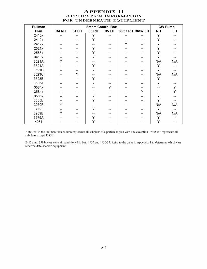
Appendix II
Application information
for underneath equipment
Pullman Steam Control Box CW Pump
Plan 34 RH 34 LH 35 RH 35 LH 36/37 RH 36/37 LH RH LH
2410x -- -- Y -- -- -- Y --
2412x -- -- Y -- -- -- Y --
2412x -- -- -- -- Y -- Y --
2521x -- -- Y -- -- -- Y --
2585x -- -- Y -- -- -- Y --
3410x -- -- Y -- -- -- Y --
3521A Y -- -- -- -- -- N/A N/A
3521A -- -- Y -- -- -- Y --
3521C -- -- Y -- -- -- Y --
3523C -- Y -- -- -- -- N/A N/A
3523E -- -- Y -- -- -- Y --
3583A -- -- Y -- -- -- Y --
3584x -- -- -- Y -- -- -- Y
3584x -- -- -- -- -- Y -- Y
3585x -- -- Y -- -- -- Y --
3585E -- -- Y -- -- -- Y --
3950F Y -- -- -- -- -- N/A N/A
3958 -- -- Y -- -- -- Y --
3959B Y -- -- -- -- -- N/A N/A
3979A -- -- Y -- -- -- Y --
4061 -- -- Y -- -- -- Y --
Note: “x” in the Pullman Plan column represents all subplans of a particular plan with one exception - “3585x” represents all
subplans except 3585E.
2412x and 3584x cars were air conditioned in both 1935 and 1936/37. Refer to the dates in Appendix 1 to determine which cars
received date-specific equipment.