Embed Size (px)
Citation preview

2The emergence of SAN technology combined with data protection, privacy, and regula-tory concerns has made storage security an important topic. SAN security risks are oftenmisunderstood and/or underestimated. Furthermore, the critical issues associated withSANs, combined with the lack of communication concerning defenses, has created asecurity gap in storage.
The purpose of this chapter is to discuss Fibre Channel SAN security risks (iSCSIsecurity risks will be discussed in Chapter 8). Each risk will be described and then fullydiscussed to allow organizations to make decisions based on their SAN data, its imple-mentation, and the organization’s risk-tolerance level.
Chapter 2 is the first of three chapters (Chapters 2, 3, and 4) where SAN security risksand the correlating attacks will be discussed. After a detailed description of the securityrisks, we discuss the details of the SAN attacks. Several sections in the next three chapterswill be followed by a self-assessment exercise, allowing administrators to test their ownexposures, vulnerabilities, and exploits.
The following topics are the primary focus of this chapter:
• SAN risks
• Risks of Fibre Channel
• Fibre Channel frame weaknesses (session hijacking)
• Fibre Channel address weaknesses (Man-in-the-Middle attacks)
SANs: Fibre ChannelSecurity
31
Dwivedi_02.qxd 10/13/05 10:35 AM Page 31

SAN RISKS
In order to discuss the risks in SAN architectures, we must evaluate it on the six areas ofsecurity discussed in Chapter 1, “Introduction to Storage Security.” Table 2.1 lists each ofthe sections, as well as their security presence in SANs.
Table 2.1 SAN Risk and Security
Security SAN Risk
Authentication Authentication aspects in most SAN environments do not exist. Fibre ChannelAuthentication Protocol (FCAP), DH-CHAP (Diffie-Hielman CHAP), and FibreChannel Security Protocol (FC-SP) have emerged to fulfill a significant gap for authenti-cation; however, most SANs are designed with the assumption that authentication hastaken place elsewhere in the architecture. For example, organizations often assumeauthentication occurring at file/record layers (databases) should be enough, whichignores network authentication at lower network levels. This would be similar to requir-ing authentication on a web application but not requiring authentication for a telnet orSSH connection to the web server. In both scenarios, data can be compromised fully.
Authentication is indirectly available through some of the applications that have accessto the SAN. Management applications, which can be used to administer storage data,usually require some type of username and password.
CT Authentication, DH-CHAP, FCAP, and FC-SP, as well as some other authenticationmodules, have been developed to authenticate node to node, node to switch, and switchto switch (discussed further in Chapter 9, “Securing Fibre Channel SANs”).
Authorization Authorization parameters are usually provided with World Wide Names (WWNs) fromthe Fibre Channel host bus adapters. WWNs can be port WWNs, which identify theport, or node WWNs, which identify the node on the fabric.
Encryption Encryption aspects in most SAN environments do not exist unless some third-party at-rest encryption device is used. Natively, Fibre Channel does not use any encryption inany of its layers (layer 0 thru layer 4).
Auditing Auditing aspects in most SANs are enabled only at the device or application level, suchas a Fibre Channel switch or a management application. There is error management viathe fabric; however, nothing for typical security auditing.
Integrity There are currently no native methods for integrity checking in Fibre Channel frames.
Availability Availability or Quality of Service (QoS) is indirectly available in layer 2 Fibre Channelframes in the Error Control fields of the frame. This aspect provides more QoS aspectsthan data availability. Availability is arguably the most important aspect of SAN security. If the storage data becomes unavailable, networks as well as applications meltdown quickly.
CHAPTER 2 SANS: FIBRE CHANNEL SECURITY
32
Dwivedi_02.qxd 10/13/05 10:35 AM Page 32

RISKS OF FIBRE CHANNEL
Risks in Fibre Channel? There are no risks in Fibre Channel, right? Wrong. The FibreChannel communications medium is absent of several entities that are required forsecure transmission. Several of the weaknesses are similar to the weaknesses in IP version4 (IPv4) and have been repeated in Fibre Channel. This section discusses the followingtopics:
• Description of Fibre Channel
• Clear-text communication
DESCRIPTION OF FIBRE CHANNEL
In order to understand the security issues with Fibre Channel SANs, we should discussthe architecture of Fibre Channel communications. Fibre Channel uses frames betweenone node to the other (similar to how IP networks use packets). Each frame contains fivelayers. The layers within each frame work with the layer below and the layer above toprovide different functions within a Fibre Channel topology. Most SANs use either aswitched Fibre Channel topology, similar to what we use in an IP-enabled switch net-work, or a Fibre Channel arbitrated loop (FC-AL). In either topology, each layer per-forms a specific function depending on the architecture that has been deployed. The fivedifferent layers of Fibre Channel frames are as follows:
• Upper Layer Protocol Mapping—FC Layer 4
• Common Services Layer—FC Layer 3
• Signaling/Framing Layer—FC Layer 2
• Transmission Layer—FC Layer 1
• Physical Layer—FC Layer 0
Similar to an IP network, Fibre Channel frames work from the physical layer, layer 0, tothe upper layers. The similarities of the two communication methods primarily end atthe physical layer; however, they do share similar security weaknesses and both haveabsent security controls. Several IP weaknesses have translated to vulnerabilities andexploits. Unfortunately, several of these attack types are also available in Fibre Channelframes. The weaknesses in Fibre Channel frames specifically target Fibre Channel layer 2,known as the framing/flow control layer (layer 2 in Fibre Channel and the Data/Networking (layer 2/layer 3) layer in an IP packet). The similarities are close in terms of
DESCRIPTION OF FIBRE CHANNEL
33
Dwivedi_02.qxd 10/13/05 10:35 AM Page 33

security weaknesses and the lack of authentication, authorization, integrity, and encryp-tion. Figure 2.1 shows the five different layers of a Fibre Channel frame.
CHAPTER 2 SANS: FIBRE CHANNEL SECURITY
34
FC-4
FC-3
FC-2
FC-1
FC-0 133 Mbps 255 Mbps 531 Mbps 1062 Mbps
Encode/Decode
Framing Protocol/Flow Control
Common Services
IPI SCSI HIPPI SBCCS 802.2 IP ATM
Figure 2.1 Five layers of a Fibre Channel frame.
Fibre Channel layer 2, the Framing Protocol/Flow Control layer, is the primary targetwhen addressing frame security weaknesses. Fibre Channel layer 2 contains the headerinformation for each frame. The header information is the location of several securityweaknesses. The contents of the header include a 24-bit address (also known as the portID) of the source node, the 24-bit address of the destination node, the sequence controlnumber, the sequence identification number, and the exchange information. The follow-ing entities are located within the frame header:
• Source Address (S_ID)—A 24-bit fabric address used to identify the source addresswhen routing frames.
• Destination Address (D_ID)—A 24-bit fabric address used to identify the destina-tion address when routing frames.
• Sequence ID (SEQ_ID)—A static number transmitted with each frame in asequence that identifies the frame as part of a session. Each frame in the same session has the same sequence ID.
• Sequence Count (SEQ_CNT)—A number that identifies individual frames within asequence. For each frame transmitted in a sequence, SEQ_CNT is incremented by 1,allowing the frames to be arranged in the correct order.
Dwivedi_02.qxd 10/13/05 10:35 AM Page 34

• Exchange ID—Information that specifies how many frames a node can accept atone time. This information is passed from one node to another.
• Originator Exchange ID (OX_ID)—The exchange information of the sender.
• Recipient Exchange ID (RX_ID)—The exchange information of the receiver.
• Type—The Upper Layer Protocol byte section.
• Routing Control (R_CTL)—Contains information such as the routing bits, whichcontain data values, and the information category, which tells the receiver what typeof data is contained in the frame.
Each node on a SAN fabric has a 24-bit fabric address that is used for a variety of things,including routing and name server information. (Note: Do not confuse the 24-bit fabricaddress with the 64-bit WWN address from the HBA.) Similar to how an IP packet isused to route packets, the 24-bit address is used to route frames from one node to theother. Figure 2.2 shows an example of the header information in Fibre Channel layer 2.
CLEAR-TEXT COMMUNICATION
35
4 bytes
Startof
Frame
24 bytes
FrameHeader
2112 byte Data Field
64 bytes
OptionalHeader
2048 byte
Payload
4 bytes
CRCError
Check
4 bytes
Endof
Frame
CTLSourceAddress
DestinationAddress
Type Seq_Cnt Seq_ID Exchange_ID
Figure 2.2 Fibre Channel layer 2.
CLEAR-TEXT COMMUNICATION
Fibre Channel communication is clear-text. The lack of security built into the differentlayers of Fibre Channel frames combined with the fact that it is clear-text allows for certain security threats to be very successful.
The lack of encryption at the frame level is not a significant negative issue, consider-ing the amount of performance impact the storage network would have if all frameswere encrypted. Furthermore, sniffing is a difficult task in a Fibre Channel SAN since it
Dwivedi_02.qxd 10/13/05 10:35 AM Page 35
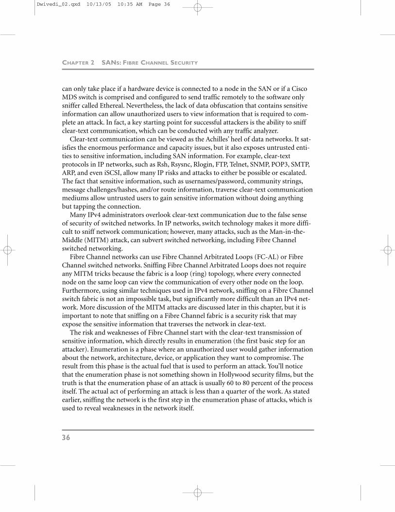
can only take place if a hardware device is connected to a node in the SAN or if a CiscoMDS switch is comprised and configured to send traffic remotely to the software onlysniffer called Ethereal. Nevertheless, the lack of data obfuscation that contains sensitiveinformation can allow unauthorized users to view information that is required to com-plete an attack. In fact, a key starting point for successful attackers is the ability to sniffclear-text communication, which can be conducted with any traffic analyzer.
Clear-text communication can be viewed as the Achilles’ heel of data networks. It sat-isfies the enormous performance and capacity issues, but it also exposes untrusted enti-ties to sensitive information, including SAN information. For example, clear-textprotocols in IP networks, such as Rsh, Rsysnc, Rlogin, FTP, Telnet, SNMP, POP3, SMTP,ARP, and even iSCSI, allow many IP risks and attacks to either be possible or escalated.The fact that sensitive information, such as usernames/password, community strings,message challenges/hashes, and/or route information, traverse clear-text communicationmediums allow untrusted users to gain sensitive information without doing anythingbut tapping the connection.
Many IPv4 administrators overlook clear-text communication due to the false senseof security of switched networks. In IP networks, switch technology makes it more diffi-cult to sniff network communication; however, many attacks, such as the Man-in-the-Middle (MITM) attack, can subvert switched networking, including Fibre Channelswitched networking.
Fibre Channel networks can use Fibre Channel Arbitrated Loops (FC-AL) or FibreChannel switched networks. Sniffing Fibre Channel Arbitrated Loops does not requireany MITM tricks because the fabric is a loop (ring) topology, where every connectednode on the same loop can view the communication of every other node on the loop.Furthermore, using similar techniques used in IPv4 network, sniffing on a Fibre Channelswitch fabric is not an impossible task, but significantly more difficult than an IPv4 net-work. More discussion of the MITM attacks are discussed later in this chapter, but it isimportant to note that sniffing on a Fibre Channel fabric is a security risk that mayexpose the sensitive information that traverses the network in clear-text.
The risk and weaknesses of Fibre Channel start with the clear-text transmission ofsensitive information, which directly results in enumeration (the first basic step for anattacker). Enumeration is a phase where an unauthorized user would gather informationabout the network, architecture, device, or application they want to compromise. Theresult from this phase is the actual fuel that is used to perform an attack. You’ll noticethat the enumeration phase is not something shown in Hollywood security films, but thetruth is that the enumeration phase of an attack is usually 60 to 80 percent of the processitself. The actual act of performing an attack is less than a quarter of the work. As statedearlier, sniffing the network is the first step in the enumeration phase of attacks, which isused to reveal weaknesses in the network itself.
CHAPTER 2 SANS: FIBRE CHANNEL SECURITY
36
Dwivedi_02.qxd 10/13/05 10:35 AM Page 36

The results of the enumeration phase determine how triumphant the actual attackwill be. For example, if the enumeration phase was able to gain significant informationabout the network, devices, applications, operating systems, routers, WWNs, and IQNs,then the penetration phase will not only be successful, but might also be far more dam-aging. Conversely, if the enumeration phase does not yield favorable results for anattacker, the actual penetration phase would be short and probably unsuccessful. Figure2.3 is a graph that shows the relationship of the enumeration and penetration phase ofan attack.
CLEAR-TEXT COMMUNICATION
37
High
PenetrationSuccess
Low
Poor StrongEnumeration Phase
Results
Start
Enumeration
Penetration
Attack
Tim
eline
Finish
Figure 2.3 Example of a sample attack timeline.
In Figure 2.3, notice the direct relationship between the enumeration phase resultsand the attack success. As more success occurs in the enumeration phase, the likelihoodof success in the attack process increases.
Now that we have established that enumeration is a very critical step in an attack, theproblems with clear-text communication leaking an abundance of sensitive informationshould be understood. The next question to address is exactly what sensitive informationin the Fibre Channel frame can actually be used in a possible attack? The following listdescribes several of the items that an unauthorized user can enumerate from a node
Dwivedi_02.qxd 10/13/05 10:35 AM Page 37

connected to the SAN. Each of these entities gives ammunition to attackers to complete asuccessful attack:
• Fabric name
• Domain identification
• Switch name server information
• Session sequence control number
• Session sequence IDs
• World Wide Names used in the fabric
• Layer-2 frame information
• 24-bit addresses
• Routing information (destination and source IDs)
• Management information (such as SES and FC-SNMP)
The enumeration of a Fibre Channel SAN does not equate into data compromise, but itdoes significantly help the process. As an attacker tries to gain enough information toperform an attack, he or she will need to enumerate the target before any attack can beexecuted. Conversely, not all enumeration is negative. An organization may send clear-text information over the network that is not considered to be sensitive; such asExchange IDs from Fibre Channel frames. The proper exercise of data classificationshould be conducted, as discussed in Chapter 1, “Introduction to Storage Security,” todetermine what type of data that traverses the network is consider public or private.
HACKING THE SAN
Hacking the SAN translates to unauthorized access to an entity or data in a storage areanetwork. In the next three chapters, we discuss the following items.
• Session hijacking
• Man-in-the-Middle attacks
• Name server pollution
• WWN spoofing
• LUN masking attacks
• Zone hopping
• Switch attacks
CHAPTER 2 SANS: FIBRE CHANNEL SECURITY
38
Dwivedi_02.qxd 10/13/05 10:35 AM Page 38

Table 2.2 is summary of the weaknesses that are discussed in the next three chapters andtheir correlating attacks.
Table 2.2 SAN Security Weaknesses and Correlation SAN Attacks
SAN Weaknesses SAN Attacks
Sequence weaknesses Session hijacking
Fabric address weaknesses Man-in-the-Middle attacks
FLOGI/PLOGI weaknesses Name server pollution
HBA weaknesses LUN masking attacks/WWN spoofing
FC switch weaknesses Zone hopping
A key idea to introduce at this time before we begin our discussion on SAN attacks isthe difference between a valid attack and a valid risk. In a given network, there are severalhundred attacks that are fully possible to execute, but only a handful of them may actu-ally pose a valid risk due to the nature of the network or the business. Hence, for eachattack described in this section, a chart is used to describe how easy or difficult the execution of the attack will be, and its risk level also will be discussed. See Figure 2.4 for the example chart.
HACKING THE SAN
39
Business Risk
Sec
uri
ty R
isk
Low High
Lo
wH
igh
<Moderate Risk>
<Moderate Risk>
<High Risk>
<Low Risk>
Figure 2.4 Security and Business Risk chart.
Dwivedi_02.qxd 10/13/05 10:35 AM Page 39

The primary purpose of the SBR chart is to place each threat described in some typeof security risk context. This chapter covers many risks and threats in Fibre ChannelSANs; many of the threats are easy to perform, but many are very difficult to execute dueto the need for physical access to the network or a hardware analyzer for sniffing. Itwould not be in the best interest of the book to simply skip the threats that are hard toactually perform, but use the SBR chart to appropriately show the risk level of eachattack after it has been described.
In Figure 2.4, notice that each area of the chart represents a different security andbusiness risk value. Items in the upper-left corner are high security risk, but low businessrisk. Risks in this area should be technically mitigated from a security perspective onlysince the business risk is low. Items in the upper-right corner are high security risk andhigh business risk. Risks in this area should be resolved immediately since they present ahigh business and security risk. Conversely, items in the lower-left corner are low secu-rity risk and low business risk. Risks in this area can often be accepted (bearable) sincethe impact is relatively low. Finally, items in the lower-right corner are low security riskand high business risk. Risks in this often need a process solution rather than a technicalsolution. The type of summary in the Security and Business Risk (SBR) chart will helpreaders understand what valid attacks are and the risks associated with them.
Now that we understand the architecture of Fibre Channel frames and the problemsassociated with clear-text communication, we will now discuss the security weaknesseswith Fibre Channel frames. The following list describes each weakness that we will discuss:
• Sequence weaknesses
• Address weaknesses
• Fabric, port, and node login weaknesses
• FLOGI, PLOGI, and address spoofing
FIBRE CHANNEL FRAME WEAKNESSES
The following sections discuss the weaknesses with Fibre Channel at the frame level.
SEQUENCE WEAKNESSES
A sequence is a set of frames transmitted unidirectionally from one entity to another inorder to maintain a session between two nodes. A frame uses a Sequence ID (Seq_ID)
CHAPTER 2 SANS: FIBRE CHANNEL SECURITY
40
Dwivedi_02.qxd 10/13/05 10:35 AM Page 40

and a Sequence Count (Seq_CNT) in each frame to identify, control, and maintain thesession. Each frame includes the Sequence ID (Seq_ID) that identifies the unique sessionthat the frame belongs to. For example, if a node were communicating with several dif-ferent entities, each session would have a unique Seq_ID to identify which frame belongsto which session. In addition to the Sequence ID, the Sequence Count is used also. TheSequence Count is used to ensure frames are placed in the right order by the entities.Each Seq_CNT is incremented by 1 for each subsequent data frame.
The Sequence ID and Sequence Count have similar responsibilities in a Fibre Channelframe as the Initial Sequence Number (ISN) in an IP packet. The ISN in an IP packet isalso responsible for maintaining a session between two nodes on an IP network.
In order for a session to be maintained between two nodes, all session informationmust be maintained. The security weakness with IP networks is the predictable (guess-able) ISN. An ISN is the core component to allow packets to become a part of an estab-lished session. If the ISN is predictable, it would potentially allow unauthorized packetsto join or hijack the session. A third-party entity could inject packets with the next relevant ISN and take control of the established session. For example, for simplicity’ssake, let’s say two of the first three packets in a session have the ISN of 123 for packetnumber one and 456 for packet number two. An attacker could probably predict that thethird packet should have an ISN of 789 to be part of the existing session. If the attackersends their packet to the target first and uses the ISN of 789, the session will then behanded over to the attacker and not the legitimate node. This means that if an entity wasable to guess the next ISN in the sequence and the entity was able to inject packets in anestablished session, the entity would own the session. See Figure 2.5 for more details.
FIBRE CHANNEL FRAME WEAKNESSES
41
PacketISN: 123
PacketISN: 345
PacketISN: 678
1. Established Session
2. Ses
sion H
ijack
Atte
mpt
3. Established Session has been Hijacked
Figure 2.5 ISN session hijacking attack.
Dwivedi_02.qxd 10/13/05 10:35 AM Page 41

As shown in Figure 2.5, a weak or predictable ISN can leave an established and trustedsession vulnerable to a session hijacking attack. A predictable value to allow/deny entitiesinto a trusted session should not be used. ISN values must be unpredictable and unique,not unpredictable or unique. This premise has also plagued HTTP (web) applications.Session identifiers in cookies used in HTTP applications, known as the Session ID, arebeing used to maintain sessions in the stateless HTTP protocols. While applications dis-tribute cookies with unique Session IDs, the Session IDs are not necessarily unpre-dictable. This allowed unauthorized users to guess or predict the Session ID and log intoapplications using another user’s existing sessions. For example, if a legitimate user and amalicious user logged on to their favorite webmail service, they would receive a cookiefrom the webmail site that contains a Session ID. Both users would present their cookie tothe site each time they want to check email. If the site granted a Session ID of 100 to thelegitimate user and 101 to the malicious user, then an attacker could guess/predict thatthe Session IDs is a three-character digit being incremented by one for any new session.The attacker could access the site under the legitimate user’s profile by changing theirSession ID in their cookie to 100 and send it to the site. Once the site receives the cookiefrom the malicious user that contains the Session ID of 100, it would recognize theattacker as the legitimate user because the site recognizes the user based on the SessionID in a user’s cookie. This would allow the attacker to log to the legitimate user’s sessionand give them access to profile pages, credit card pages, and account information.
As stated in the Preface, attacks don’t change, but they do get modified. Similar to thesession hijacking weaknesses in IP ISN packets, which was introduced over 15 years ago,and Session IDs in HTTP cookies, the Sequence ID and Sequence Counts in FibreChannel frames are unique values, but they are predictable. The Sequence Count value isincremented by one, a very predictable pattern. Furthermore, the Sequence ID is aunique number, but is also a static number that does not change within the session.Therefore, of the two entities that maintain the session in a Fibre Channel frame, one is astatic value and the other is a value that increments by one, both of which can allow anunauthorized entity to predict or guess values and inject their own frames to hijack asession. For example, let’s say two nodes are communicating on a Fibre Channel net-work—they have a Sequence ID of 12, and the first frame has a Sequence Count of1117171342 and the second frame has a Sequence Count of 1117171343. An unautho-rized node could inject frames to the target node with the Sequence ID of 12, since theframe is in clear-text and the value does not change, and predict the next SequenceCount of 1117171344 in order to hijack the session. Notice that although 1117171342 isa long and unique number, the first four digits is the date (November 17th or 1117) andthe last six digits is time (5:13 and 42 seconds or 17:13:42). By doing some simple pat-tern matching and predictions, it is easy to figure out that the next few frames will havethe Sequence Count of 1117171344, 1117171345, and 1117171346.
CHAPTER 2 SANS: FIBRE CHANNEL SECURITY
42
Dwivedi_02.qxd 10/13/05 10:35 AM Page 42

What does this mean? Well, this does not mean that you can go download Hunt,Ettercap, or WebProxy and begin to perform session hijack attacks on Fibre ChannelSANs (Hunt, Ettercap, and WebProxy are IP/Application tools to hijack sessions in IPnetworks or web applications). Although the weaknesses are there in a Fibre Channelframe, the threat and exposure is relatively low. A Fibre Channel analyzer is required tomodify frames and inject them into established session. With speeds up to 2gb/sec, this isnot an easy task. Nonetheless, the weakness of session management with the Seq_ID andSeq_CNT fields in a Fibre Channel frame do exist, which tells us that security may havenot been a significant factor when developing session management for Fibre Channel orFibre Channel-enabled products.
SESSION HIJACKING
Session hijacking is the act of an untrusted third party intercepting and controlling(hijacking) a valid session between two trusted entities. Telnet is a good example of atrusted session between two entities that can be hijacked by an anonymous third partyon the segment if weak ISNs are being used for the TCP packets. Figure 2.6 shows ahigh-level example of session hijacking.
FIBRE CHANNEL FRAME WEAKNESSES
43
Initial Session
Sessio
n Hija
ckServer A Server B
Server C
Figure 2.6 Sample session hijacking between two trusted entities.
Session hijacking was first introduced many years ago in the IP networking world for weak and predictable Initial Sequence Numbers in TCP headers for IP packets.
Dwivedi_02.qxd 10/13/05 10:35 AM Page 43

The attack became quite easy to execute with IP tools such as Hunt (http://lin.fsid.cvut.cz/~kra/#HUNT) and Ettercap (http://ettercap.sourceforge.net/). Session hijackingresurfaced in the application world when weak and predictable session IDs becameapparent in application cookies to maintain state in web (HTTP) communication.Similar to our discussion in Chapter 1 on how several attacks don’t change, but get modified, the idea of session hijacking can be applied to Fibre Channel frames also.
ASSESSMENT EXERCISE
In order to better understand session hijacking, we will demonstrate an example usingan IP network and also using the tool called Hunt, which works solely on the Unix/Linux platform. While Hunt is a great tool, you might have to try it several times to get itto work correctly. Based on Figure 2.6, server C will be the malicious user hijacking a ses-sion from server A to server B. The following steps outline the method to performsession hijacking:
1. On server C, download Hunt from http://lin.fsid.cvut.cz/~kra/#HUNT.
2. Unzip Hunt:
a. cd /usr/local/bin
b. gunzip --c hunt.tar.gz | tar xvf --
3. Compile Hunt:
c. cd /usr/local/bin/hunt-1.5
d. make
e. make install
4. Execute Hunt:
f. ./hunt
5. On server A, telnet to server B, using the telnet command:
g. telnet serverB
6. On server C, choose option A (see Figure 2.7).
7. On a hub (or a switch using arpspoof), you should see the Telnet session from serverA (10.10.80.122) to server C (128.101.81.1) with Hunt.
8. At the choose conn> prompt, enter 0 to hijack the session (see Figure 2.8).
CHAPTER 2 SANS: FIBRE CHANNEL SECURITY
44
Dwivedi_02.qxd 10/13/05 10:35 AM Page 44

Figure 2.7 Hunt’s options.
FIBRE CHANNEL FRAME WEAKNESSES
45
Figure 2.8 Telnet session with Hunt.
9. Accept all the defaults (labeled in brackets) until you see the target session (see Figure 2.9).
Dwivedi_02.qxd 10/13/05 10:35 AM Page 45

Figure 2.9 Hunt’s defaults.
10. Ensure the user on server A continues to type and is not sitting idle with the telnetprompt.
11. Back on server C, if the user on server A is using the Telnet session, you will be ableto either watch the session or hijack it at any time by pressing the Enter key a coupleof times (preferably after the user has su to root!!!). Once you have hijacked the ses-sion, Hunt will inform you that “you took over the connection.”
12. Done. Server C has now hijacked the Telnet session from server A to server B due topoor session information in the Initial Sequence Number of the TCP header (seeFigure 2.10).
Based on our attack here, the IP session hijacking will be classified as a high security risk,since authentication can be subverted from a malicious attacker. Additionally, theattacker will also get a high business risk, since a successful IP session hijack attack willallow an unauthorized user to gain access to machines containing sensitive data. SeeFigure 2.11 for an SBR chart.
CHAPTER 2 SANS: FIBRE CHANNEL SECURITY
46
Dwivedi_02.qxd 10/13/05 10:35 AM Page 46

Figure 2.10 Successful hijacked session from server A.
FIBRE CHANNEL FRAME WEAKNESSES
47
Business Risk
Sec
uri
ty R
isk
Low High
Lo
wH
igh
IP Session Hijacking
Figure 2.11 SBR chart for IP session hijacking.
SESSION HIJACKING—FIBRE CHANNEL
In a Fibre Channel architecture, in order for two Fibre Channel nodes to communicatewith each other, an established session must be made. The session information is
Dwivedi_02.qxd 10/13/05 10:35 AM Page 47

managed by the Sequence Count number (Seq_CNT) and the Sequence Identificationnumber (SEQ_ID). The definitions for Sequence Count numbers and SequenceIdentification numbers are as follows:
• Sequence Count (SEQ_CNT)—A number identifies individual frames within asequence. For each frame transmitted in a sequence, SEQ_CNT is incremented by 1,allowing the frames to be arranged in the correct order.
• Sequence ID (SEQ_ID)—A static number transmitted with each frame in asequence that identifies the frame as part of a session. Each frame in the same session has the same Sequence ID.
The session information between two FC nodes is the entity that is in charge of main-taining a session. For example, if 100 frames were delivered from several nodes toanother single node, there needs to be a method to understand which frame came fromwhich node and to organize the frames in their correct order. In order to complete this,the Seq_ID and Seq_CNT are used. The Seq_ID and Seq_CNT will tie each frame to aparticular session and place it in its correct order.
The issue with session management starts with the lack of Fibre Channel authentica-tion when sending or receiving frames. Similar to the IP and Hunt example earlier, inorder to break in and hijack a session, a malicious user could send frames to an author-ized node with the correct Seq_ID and Seq_CNT (using the source address (S_ID) as theattacker and not the original session holder), thus, transferring the session’s control tothe malicious user. Furthermore, since the Seq_ID never changes (which makes it veryeasy to guess), and the Seq_CNT number increments by the value of one (which makesit very easy to predict), the hijacking process of the session is quite trivial.
Although the attack is very trivial, as demonstrated with IP/Hunt as well as web appli-cations and session identifiers, currently there are no automated tools to perform thistype of attack. A Fibre channel analyzer would have to be used to actually perform ses-sion hijacking on FC frames, rendering the attack as a high security threat, but a low riskitem (see Figure 2.12).
CHAPTER 2 SANS: FIBRE CHANNEL SECURITY
48
Dwivedi_02.qxd 10/13/05 10:35 AM Page 48

Figure 2.12 SBR chart for Fibre Channel session hijacking.
ASSESSMENT EXERCISE
In order to fully understand the Fibre Channel hijacking attack, the following stepsdescribe the attack process according to Figure 2.13:
1. Node Kusum makes an established connection with node Neeraja.
2. Node Kusum and node Neeraja exchange frames for communication.
3. Using a Fibre Channel traffic analyzer, the malicious user, Lakshman, identifies thestatic value for the Seq_ID and the Seq_CNT number.
4. Lakshman then injects frames to Neeraja with the Seq_ID, taken from the framesbetween Kusum and Neeraja, and then increments the Seq_CNT number by one,which will identify the next frame in the session.
5. Neeraja receives the frame(s) from Lakshman, and because the frames have the cor-rect Seq_ID and the correct value for the Seq_CNT, the frames are regarded as thenext set of frames in the session.
6. Because the S_ID of the Lakshman’s frames are from a different address, the sessionis then handed to that node wherever the session last left off.
FIBRE CHANNEL FRAME WEAKNESSES
49
Business Risk
Sec
uri
ty R
isk
Low High
Lo
wH
igh
IP Session HijackingIP Man-in-the-Middle
Fibre ChannelSession Hijacking
Fibre ChannelMan-in-the-Middle
Dwivedi_02.qxd 10/13/05 10:35 AM Page 49

Figure 2.13 Topology for session hijacking.
The technical details of the attack are obviously more complicated, but generally followthe steps outlined beforehand. The first step would be to enumerate the frame informa-tion from the two trusted entities. Using any type of Fibre Channel fabric analyzer or IPsniffer with an IP to Fibre Channel connector, there are a variety of methods to do thisattack depending on the type of architecture. For example, if a fabric loop topology hadbeen deployed (FC_AL), the analyzer can see all the traffic in the loop of every node con-nected to the fabric. In a switched architecture, the analyzer would need to be connectedto the core FC switch and also within the same routing segment of the target. Once thetargets have been identified and enumerated by the traffic analyzer, the following fieldsin the header part of the frame are important for the attack: S_ID, D_ID, OX_ID, RX_ID,Seq_ID, and Seq_CNT.
Within Fibre Channel layer 2, you would modify the header information with yourtraffic analyzer of the frame that you will generate in order to complete the attack. Whencrafting the frame, the S_ID would change from the original source fabric address to thefabric address of the attacker. The D_ID would remain the same, which is the fabric
CHAPTER 2 SANS: FIBRE CHANNEL SECURITY
50
FrameSeq_CNT: 102Seq_ID: 880
FrameSeq_CNT: 103Seq_ID: 880
1. Established Session
2. Ses
sion H
ijack
Atte
mpt
3. Established Session Has Been Hijacked
Neeraja
Lakshman
Kusum
FrameSeq_CNT: 101Seq_ID: 880
7. Lakshman has hijacked the session from Kusum and now has an established connec-tion to Neeraja without any authentication or authorization.
8. Despite the fact that Lakshman has hijacked the session, Neeraja still thinks theestablished connection is with Kusum.
Dwivedi_02.qxd 10/13/05 10:35 AM Page 50

address of the target (while both entities are technically targets, the entity that is on thereceiving end of the session is the real target). The OX_ID and RX_ID values would haveto be consistent with the original source (Kusum in our previous example) since themalicious node would need to be able to send and receive the same amount of frames asthe original source and consequently send the correct amount of frames to the targetspecified in the original RX_ID field. The Seq_ID field will also need to remain identicalto the original in order to ensure the target node considers the frame(s) as part as thelegitimate session. Unlike the Seq_ID, the Seq_CNT field will not remain identical butrather will need to be incremented by one in order for the target to consider that frameas the next legitimate frame in the session. This is probably the trickiest part of theattack; even though the act of incrementing the Seq_CNT by one is a trivial procedure, itis not as easy to determine what Seq_CNT is the last one. For example, using your trafficanalyzer, you are able to view the Seq_CNT number of all sessions, but by the time yousend your frame(s), the legitimate source may already have sent a frame with thatSeq_CNT, thus leaving your frame useless. Although this attack takes some trial anderror, a good way to ensure that the attack works correctly is to estimate what theSeq_CNT number will be by the time you have the opportunity to send your frame(s)and to set up multiple instances of malicious frames, each using a Seq_CNT that couldpossibly be the next legitimate one by the time it reaches the target. After you have suc-cessfully done this with your traffic analyzer, you will notice that your node will startreceiving the frames from the target with the same Seq_ID and Seq_CNT from the origi-nal session, despite the fact that you have not officially logged into the node (NLOGIN).
ATTACK SUMMARY: SESSION HIJACKING
Attack description—Hijacking a data or management session by guessing the sequencecontrol number (SEQ_CNT) and the sequence identification number (SEQ_ID) of aFibre Channel frame.
Risk level—High. An unauthorized entity could gain access to an authorized manage-ment session or simply modify the sequence numbers randomly and attempt to performa denial-of-service attack.
Difficulty—High. This is a sophisticated attack that requires deep knowledge of FibreChannel frames and the use of a hardware and software traffic analyzer.
Best practice—None to date; however, the use of strong or unpredictable SEQ_CNT orSEQ_ID would mitigate this issue in the future. Ask your storage vendor about frameauthentication or integrity options.
FIBRE CHANNEL FRAME WEAKNESSES
51
Dwivedi_02.qxd 10/13/05 10:35 AM Page 51

FIBRE CHANNEL ADDRESS WEAKNESSES
Now that we have established that attacks don’t change, but they do get modified, let’sdiscuss another attack that stems network and application history. Manipulation of the24-bit fabric address can cause significant damage and denial of service in a SAN.
Each node in a SAN has a 24-bit fabric address that is used for routing, among otherthings. Along with routing frames correctly to/from their source and destinations, the24-bit address is also used for name server information. The name server is a logicaldatabase in each Fibre Channel switch that correlates a node’s 24-bit fabric address totheir 64-bit WWN. Additionally, the name server is also responsible for other items, suchas mapping the 24-bit fabric address and 64-bit WWN to the authorized LUNs in theSAN. Furthermore, address information is also used for soft and hard zoning procedures(discussed in the Chapter 4, “SANs: Zone and Switch Security”). The 24-bit fabricaddress of a node determines route functions with soft and hard zoning procedures,specifically if a frame is allowed to pass from one zone to the other. While there are sev-eral other uses of the 24-bit address, the use of the address in name servers and zoningprocedures are by far the most important in terms of security.
The major issues with the 24-bit address is that it is used for identification purposesfor both name server information and soft/hard zone routing, almost like an authoriza-tion process, but it is an entity that can be easily spoofed. Using any traffic analyzer, the24-bit source address of a Fibre Channel frame could be spoofed as it performs bothPLOGI (Port Login) and FLOGI (Fabric Login) procedures.
In Fibre Channel, there are three different types of login—Port Login, Fabric Login,and Node Login. Two can be corrupted with a spoofed 24-bit fabric address. Before wediscuss how spoofing disrupts these processes, let’s discuss the login types first.
FABRIC LOGIN (FLOGI), PORT LOGIN (PLOGI), AND NODE LOGIN
(NLOGI)
The Fabric Login (FLOGI) process allows a node to log in to the fabric and receive anassigned address from a switch. The FLOGI occurs with any node (N_Port or NL_Port)that is attached to the fabric. The N_Port or NL_Port will carry out the FLOGI with anearby switch. The node (N_Port or NL_Port) will send a FLOGI frame that contains itsnode name, its N_Port name, and any service parameters. When the node sends its infor-mation to the address of 0xFFFFFE, it uses the 24-bit source address of 0x000000because it hasn’t received a legitimate 24-bit address from the fabric yet. The FLOGI willbe sent to the well-known fabric address of 0xFFFFFE, which is similar to the broadcastaddress in an IP network (though not the same). The FC switches and fabric will receivethe FLOGI at the address of 0xFFFFFE. After a switch receives the FLOGI, it will give the
CHAPTER 2 SANS: FIBRE CHANNEL SECURITY
52
Dwivedi_02.qxd 10/13/05 10:35 AM Page 52

N_Port or NL_Port a 24-bit address that pertains to the fabric itself. This 24-bit addresswith be in the form of Domain-Area-Port address from, where the Domain is the uniquedomain name (ID) of the fabric, Area is the unique area name (ID) of the switch withinthe domain, and Port is the unique name (ID) of each port within the switch in the fab-ric. Table 2.3 shows how the 24-bit address is made.
Table 2.3 24-Bit Addresses
24-Bit Address Type Description
8-bit domain name Unique domain ID in a fabric. Valid domain IDs are between 1 and 239.
8-bit area name Unique area ID on a switch within a fabric. Valid area IDs are between 0 and 255.
8-bit port name Unique port ID within a switch in a fabric. Valid port IDs are between 0 and 255.
A 24-bit address (port ID) uses the following formula to determine a node’s address:
Domain_ID x 65536 + Area_ID x 256 + Port_ID = 24 bit Address
An example address for and node on the first domain (domain ID of 1), on the firstswitch (area ID of 0), and the first port (port ID of 1), would be the following:
1 x 65536 + 0 x 256 + 1 = 65537 (Hex: 0x10001)
After the node has completed the FLOGI and has a valid 24-bit fabric address, it willperform a Port Login (PLOGI) to the well-known address of 0xFFFFFC to register itsnew 24-bit address with the switch’s name server, as well as submit information on its64-bit port WWN, 64-bit node WWN, port type, and class of service. The switch thenregisters that 24-bit fabric address, along with all the other information submitted, to thename server and replicates that information to other name servers on the switch fabric.Figures 2.14 and 2.15 show the FLOGI and PLOGI processes.
FIBRE CHANNEL ADDRESS WEAKNESSES
53
FLOGI FrameSource Address: 0x000000Destination Address: 0xFFFFFE
Node on Fabric
Fibre ChannelSwitch
Accept FrameContains the new 24-bit addressof the node using the Domain,Area, and Port ID (e.g. 0x10001)
Figure 2.14 FLOGI process.
Dwivedi_02.qxd 10/13/05 10:35 AM Page 53
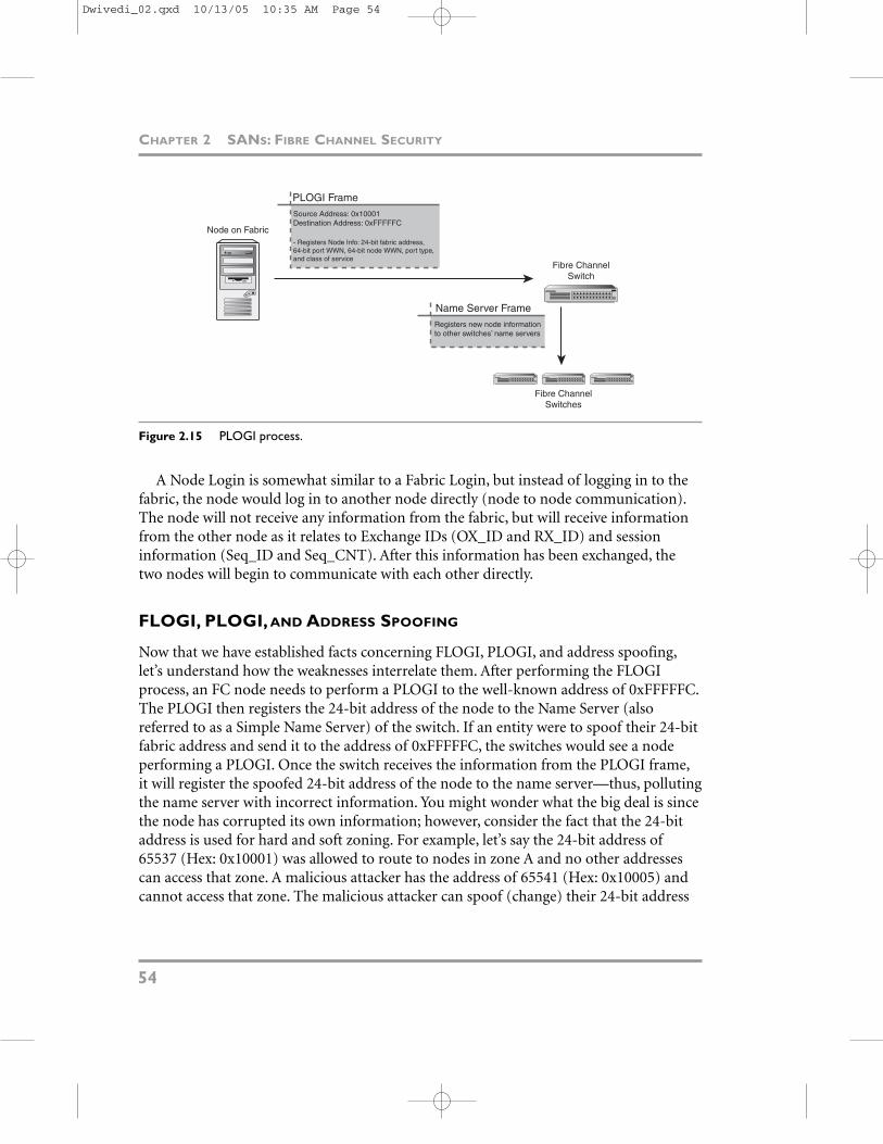
Figure 2.15 PLOGI process.
A Node Login is somewhat similar to a Fabric Login, but instead of logging in to thefabric, the node would log in to another node directly (node to node communication).The node will not receive any information from the fabric, but will receive informationfrom the other node as it relates to Exchange IDs (OX_ID and RX_ID) and session information (Seq_ID and Seq_CNT). After this information has been exchanged, thetwo nodes will begin to communicate with each other directly.
FLOGI, PLOGI, AND ADDRESS SPOOFING
Now that we have established facts concerning FLOGI, PLOGI, and address spoofing,let’s understand how the weaknesses interrelate them. After performing the FLOGIprocess, an FC node needs to perform a PLOGI to the well-known address of 0xFFFFFC.The PLOGI then registers the 24-bit address of the node to the Name Server (alsoreferred to as a Simple Name Server) of the switch. If an entity were to spoof their 24-bitfabric address and send it to the address of 0xFFFFFC, the switches would see a nodeperforming a PLOGI. Once the switch receives the information from the PLOGI frame,it will register the spoofed 24-bit address of the node to the name server—thus, pollutingthe name server with incorrect information. You might wonder what the big deal is sincethe node has corrupted its own information; however, consider the fact that the 24-bitaddress is used for hard and soft zoning. For example, let’s say the 24-bit address of65537 (Hex: 0x10001) was allowed to route to nodes in zone A and no other addressescan access that zone. A malicious attacker has the address of 65541 (Hex: 0x10005) andcannot access that zone. The malicious attacker can spoof (change) their 24-bit address
CHAPTER 2 SANS: FIBRE CHANNEL SECURITY
54
PLOGI FrameSource Address: 0x10001Destination Address: 0xFFFFFC
- Registers Node Info: 24-bit fabric address,64-bit port WWN, 64-bit node WWN, port type,and class of service
Node on Fabric
Fibre ChannelSwitch
Name Server FrameRegisters new node informationto other switches’ name servers
Fibre ChannelSwitches
Dwivedi_02.qxd 10/13/05 10:35 AM Page 54

to match 65537 (0x10001) and then route frames to the restricted zone A, despite beingunauthorized to do so. Spoofing the 24-bit address during PLOGI negates any route-based zoning rules that may have been applied. The simple process of spoofing now creates the ability to route (hop) across hard and soft zoning rules. Figure 2.16 shows the FLOGI/PLOGI spoofing process.
MAN-IN-THE-MIDDLE ATTACKS
55
FLOGI FrameSource Address: 0x000000Destination Address: 0xFFFFFE
MaliciousAttacker
Fibre ChannelSwitch
Accept FrameContains the new 24-bit addressof the node using the Domain,Area, and Port ID (e.g. 0x10005)
Fibre ChannelSwitches
Address: 0x10005
Spoofed PLOGI FrameSpoof Source Address: 0x10001Destination Address: 0xFFFFFC
- Register Node Info: Spoofed 24-bit fabric
address, 64-bit port WWN, 64-bit node WWN,
port type, and class of service
Polluted Name Server FrameRegisters new node information (includingfake 24-bit address that correlates to theattackers WWN) to other switches’ nameservers
Figure 2.16 FLOGI/PLOGI spoofing process.
We will take this idea a bit further in the next section, “Man-in-the-Middle Attacks,”when I discuss the issues of spoofing the 24-bit fabric address and spoofing a nodeWWN. The fact is that this attack is very severe by breaking the integrity of any hard orsoft zoning rules. However, a traffic analyzer is required to perform this attack, thus creating barriers to perform the attack itself.
MAN-IN-THE-MIDDLE ATTACKS
A Man-in-the-Middle (MITM) attack is the act of an untrusted third party interceptingcommunication between two trusted entities. For example, when you call a friend on the
Dwivedi_02.qxd 10/13/05 10:35 AM Page 55

telephone, you dial his or her phone number and wait for an answer. When your friendpicks up the phone, you then begin communicating with him or her. In a MITM attack,a malicious user would intercept the connection between you and your friend. Instead oftalking to your friend directly, you would actually be communicating through a mali-cious third party. The malicious third party would then connect you to your friend. Bothyou and your friend would begin communicating, not knowing that an unauthorizedentity has connected you both and is listening to every word of the conversation. It is likea three-way call, but two of the three callers don’t know that there is a third person lis-tening.
In the digital world, the untrusted third party plays the role of a router, but unlike anauthorized router, the untrusted third party should not have permission to view, modify,or intercept any of the communication between the two trusted entities. Figure 2.17shows a high-level example of a Man-in-the-Middle attack.
CHAPTER 2 SANS: FIBRE CHANNEL SECURITY
56
Normal Communication
Man-in-the-Middle Attack
Server AIP: 172.16.1.101
Server BIP: 172.16.1.117
SwitchIP: 172.16.1.1
MAC: 00-00-c5-0e-57-63
SwitchIP: 172.16.1.1
MAC: 00-00-c5-0e-57-63
Server A Server B
Server CUntrusted Third Party
IP: 172.16.1.150MAC: 00-A0-CC-69-89-74
1 2
1 4
2
3
Figure 2.17 Sample Man-in-the-Middle attack.
Dwivedi_02.qxd 10/13/05 10:35 AM Page 56

Man-in-the-Middle attacks were first introduced many years ago in the IP networkingworld. Unauthenticated OSI layer 2 Address Resolution Protocol (ARP) packets couldupdate ARP tables (tables that match a node’s IP address to their machine (MAC)address) in switches and/or operating systems. The purpose of the MITM is to sniff on aswitch. A switch will only transmit information to the correct port, not allowing anyother ports to see any communication that is not theirs. On the other hand, a hub is adumber device that allows all ports to see all communication, making it quite easy tosniff a neighbor’s traffic. Many switches are layer 2 devices, meaning that they can trans-mit packets from one port on a switch to another without the need for an IP address, butwith a node’s machine address (MAC). For example, on a Windows operating system,type ipconfig /all from the command line and then press Enter. Notice the physicaladdress is the machine address of your node, which is actually the MAC address of yourNetwork Interface Card (NIC). The MAC address comes from the manufacturer of theNIC to identify it. If your node wanted to speak to another node via a layer 2 switch, itwould use the MAC address and not your IP address. Layer 2 routing is common for per-formance reasons, allowing switches to transfer packets quickly across the network. Oncethe packets get to a layer 3 device, such as a router, then a node’s IP address can be used.
Since ARP is a layer 2 protocol, it uses a node’s MAC address to identify nodes andtransfer packets. ARP is similar to Name Servers in the Fibre Channel world, whereName Servers match the WWN of HBAs to the 24-bit fabric address (as well as a fewother items, such as zones and LUN access).
MAN-IN-THE-MIDDLE ATTACKS—IP
Before we can begin to understand the idea about a Fibre Channel Man-in-the-Middleattack, let’s first understand the concept using the IP protocol. An entity using IP, such asa switch or an operating system, will send out ARP requests when it is trying to commu-nicate with other entities. For example, if server A wanted to communicate with server B,which has the IP address of 172.16.1.1 and the MAC address of 00-0A-CC-69-89-74,server A would send out an ARP request asking, “Who is 172.16.1.1?” Then the switch orthe operating system would respond, replying with its MAC address, which is 00-0A-CC-69-89-74. The issue with ARP, which we will also address with Fibre Channel nameservers, is that any malicious entity could send out an ARP reply instead of the actualserver. For example, if you stepped outside your home and yelled out, “What is theaddress of the post-office,” a malicious neighbor could say, “I am the post-office; pleasesend your mail to me.” If you believed this malicious neighbor without asking for proof,then your mail would be compromised. This is how ARP works, without any authentica-tion. A malicious user could send out ARP replies with the incorrect information.
MAN-IN-THE-MIDDLE ATTACKS
57
Dwivedi_02.qxd 10/13/05 10:35 AM Page 57

Since there is no authentication with ARP, similar to how there is no authentication withPLOGI in Fibre Channel fabrics, an entity receiving an ARP reply from an attackerwould update their routing table with the incorrect information. Furthermore, even if anode did not send out an ARP request, which would request the MAC address of a spe-cific IP address, it doesn’t mean it won’t receive an ARP reply and update its own routingtable. For example, a malicious user could send out ARP replies to the entire networksegment, telling each entity that the MAC address of the router, which is 172.16.1.1, isactually the MAC address of the malicious entity. When one node tries to communicateto any other node by going through the default router, it will actually be going to themalicious entity first, since it is using the MAC address of the malicious entity for layer 2routing.
ASSESSMENT EXERCISE
Let’s attempt an IP Man-in-the-Middle attack using the following steps to better under-stand the issue:
1. Ensure you are on a test network and you have full permission from your networkadministrator because a Man-in-the-Middle attack will cause network disruption.
2. In our example using Figure 2.17, servers A and B will try to communicate with oneanother and server C will intercept that traffic.
3. Download Cain and Abel to server C from http://www.oxid.it/cain.html.
4. Type ipconfig on server A. Notice that is the default route listed as “GatewayAddress.” In our example, the default gateway is 172.16.1.1. Therefore, when server Atries to communicate to server B, it would go through its router first, which is172.16.1.1 (see Figure 2.18).
5. Still on server A, ping its gateway address by typing ping <default gateway>, such asping 172.16.1.1. See Figure 2.19. Now that server A has pinged the router, it will haveits MAC address in its ARP table. Type arp –a to see the dynamic ARP table in thesystem (see Figure 2.19).
6. Switch to server C (the malicious user). Use Cain and Abel to enable server C to send out ARP replies to the network segment, telling everyone that the address of172.16.1.1 is actually associated with the MAC address of 00-00-86-59-C8-94, whichis the MAC address of server C, not the MAC address of the router. The MACaddress of the router is 00-00-C5-0E-57-63, which we know from the arp –a com-mand that told us the MAC address of the default router (172.16.1.1). Perform thesteps in the next exercise on server C.
CHAPTER 2 SANS: FIBRE CHANNEL SECURITY
58
Dwivedi_02.qxd 10/13/05 10:35 AM Page 58
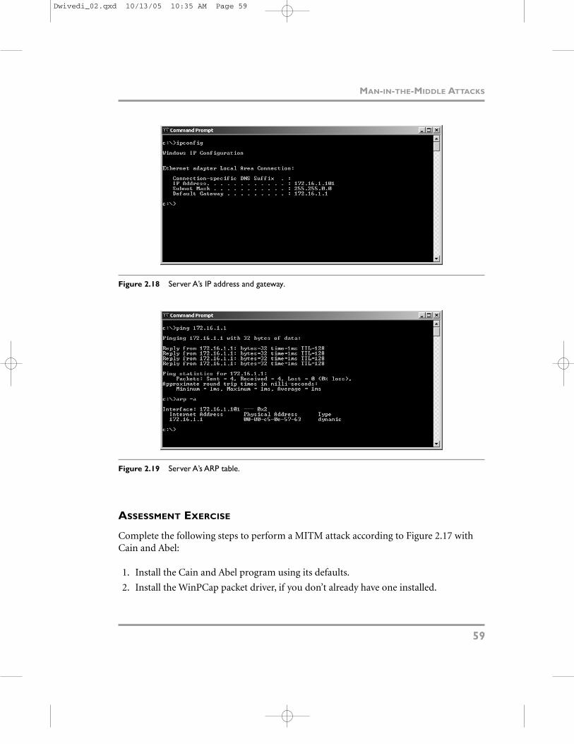
Figure 2.18 Server A’s IP address and gateway.
MAN-IN-THE-MIDDLE ATTACKS
59
Figure 2.19 Server A’s ARP table.
ASSESSMENT EXERCISE
Complete the following steps to perform a MITM attack according to Figure 2.17 withCain and Abel:
1. Install the Cain and Abel program using its defaults.
2. Install the WinPCap packet driver, if you don’t already have one installed.
Dwivedi_02.qxd 10/13/05 10:35 AM Page 59

3. Reboot.
4. Launch Cain and Abel (Start -> Programs -> Cain).
5. Select the icon in the upper-left corner that looks like a green Network InterfaceCard.
6. Ensure that your NIC card has been identified and enabled correctly by Cain.
7. Select the Sniffer tab.
8. Select the + symbol in the toolbar.
9. The MAC Address Scanner window appears. This enumerates all the MAC addresseson the local subnet. Hit OK. See Figure 2.20 for the results.
CHAPTER 2 SANS: FIBRE CHANNEL SECURITY
60
Figure 2.20 MAC Address Scanner results.
10. Select the APR tab on the bottom of the tool to switch to the ARP Pollution Routingtab.
11. Select the + symbol on the toolbar to show all the IP addresses and their MACs (seeFigure 2.21).
Dwivedi_02.qxd 10/13/05 10:35 AM Page 60

Figure 2.21 IP addresses and their MACs.
12. On the left hand side of Figure 2.22, choose the target for your MITM attack. Mostlikely this will be the default gateway in your subnet, so all packets will go throughyou first before the real gateway of the subnet.
13. Once you select your target, which is 172.16.1.1 in our example, you then select thehosts on the right side that you want to intercept traffic. This value can be all thehosts in the subnet or one particular host. We will choose one host, which will be172.16.1.119. Select OK (see Figure 2.22).
MAN-IN-THE-MIDDLE ATTACKS
61
Figure 2.22 Man-in-the-Middle targets.
Dwivedi_02.qxd 10/13/05 10:35 AM Page 61

14. Now select the yellow and black icon (second one from the left) to officially start theMITM attack. This will allow server C to start sending out ARP responses on thenetwork subnet, telling 172.16.1.119 that the MAC address of 172.16.1.1 has beenupdated to 00-00-86-59-C8-94 (see Figure 2.23).
CHAPTER 2 SANS: FIBRE CHANNEL SECURITY
62
Figure 2.23 Man-in-the-Middle attack in process with ARP poisoning.
15. At this point, all traffic from server A to server B is going to server C first and thenon its appropriate route. Server C can open up a network sniffer to view all the traf-fic. Additionally, Cain has a Passwords tab at the bottom that will capture the pass-word of major protocols such as FTP, HTTP, IMAP, POP3, Telnet, and VNC. It willalso capture password hashes such as Kerberos and IPsec using IKE (see Figure 2.24).
Layer 2 in the OSI model (Ethernet) is a key target for attackers. The attack becomesquite easy to execute with IP tools such as Windoze Interceptor, Dsniff, and Cain andAbel. Man-in-the-Middle attacks have also resurfaced in the application world using thesame preceding techniques, but with cookies and certificates instead of ARP packets.
Dwivedi_02.qxd 10/13/05 10:35 AM Page 62

Similar to our discussion in Chapter 1 on how several attacks don’t change but insteadget modified, the idea of Man-in-the-Middle attacks can be applied to Fibre Channelframes also.
MAN-IN-THE-MIDDLE ATTACKS
63
Figure 2.24 Capture password hashes due to the Man-in-the-Middle attack.
The MITM attack is possible due to the lack of authentication in ARP packets as wellas the insecurities of IPv4. As demonstrated with Cain and Abel, the attack can be quitetrivial, rendering the attack as a high security threat, but a high-risk item (see the SBRchart in Figure 2.25).
Dwivedi_02.qxd 10/13/05 10:35 AM Page 63

Figure 2.25 SBR chart—IP Man-in-the-Middle.
MAN-IN-THE-MIDDLE ATTACKS—FIBRE CHANNEL
In Fibre Channel fabrics, Man-in-the-Middle attacks are more difficult than IP and beara smaller amount of risk; however, the weaknesses in the fabric are still very apparent.
NAME SERVER POLLUTION
In order to conduct a MITM attack on a Fibre Channel network, name server pollutionis required. Described earlier in this chapter, there are significant weaknesses in theFLOGI and PLOGI processes that can be used to pollute the name server.
When performing a FLOGI, a Fibre Channel node will use the source address of0x000000 because it does not have a valid S_ID yet. The node will send its frame to thedestination address (D_ID) of 0xFFFFFE, which is similar to a broadcast address forFibre Channel fabrics. After the switches receive the frame at the address of 0xFFFFFE, itwill return an Accept frame, known as an ACC, to the node with its new 24-bit address,giving the node a valid fabric address. After the node has received the ACC frame and itsnew 24-bit address, it will then perform a PLOGI. The PLOGI will send its new 24-bitaddress to the address of 0xFFFFFC, registering its new address to the switch’s nameservers.
The security weakness is that a malicious node can craft a spoofed PLOGI frame andsend it to the address of 0xFFFFFC. The malicious node could complete the FLOGI
CHAPTER 2 SANS: FIBRE CHANNEL SECURITY
64
Business Risk
Sec
uri
ty R
isk
Low High
Lo
wH
igh
IP Session HijackingIP Man-in-the Middle
Fiber ChannelSession Hijacking
Dwivedi_02.qxd 10/13/05 10:35 AM Page 64

process, but instead of responding with its real 24-bit address, it could use a spoofed 24-bit address of a target during the PLOGI. Since the malicious node knows the address tosend PLOGI responses to (0xFFFFFC), the act of inserting the 24-bit address is not achallenge. The switch name server would receive the spoofed PLOGI frame at theaddress 0xFFFFFC and will update its name server with the incorrect information. For apersistent attack, the malicious node would continue to send PLOGI frames at theaddress of 0xFFFFFC, continuously updating the name server with incorrect informa-tion and leaving the target with the actual 24-bit address completely out of the process. Adetailed description of the contents of each frame is depicted in Figure 2.26.
MAN-IN-THE-MIDDLE ATTACKS
65
FLOGI FrameSource Address: 0x000000Destination Address: 0xFFFFFE
Malicious Nodeon Fabric Fibre Channel
Switch
Accept FrameNew 24-bit Address: 0x10008
Contains the new 24-bit addressof the node using the Domain,Area, and Port ID (e.g. Domain 1, Area 0, and Port 1=0x10008)
PLOGI Frame(s)Spoofed Source Address: 0x10001Destination Address: 0xFFFFFC
- Registers Node Info: Spoofed 24-bit fabric
address, 64-bit port WWN, 64-bit node WWN,
port type, and class of service
Name Server FrameUpdates name server table withspoofed 24-bit address andregisters new node informationto other switches’ name servers
1
2
3
4
Name Server Table
Figure 2.26 Name server pollution process.
MITM ATTACK
In order for two Fibre Channel nodes to communicate with each other, they must knowthe others’ 24-bit address and port ID on the fabric. The fabric address is given andupdated during the FLOGI and PLOGI processes, which also has no authenticationprocess (similar to ARP). The port ID is the physical port number that the node is connected to on the switch. If one node wanted to communicate to another node,
Dwivedi_02.qxd 10/13/05 10:35 AM Page 65

it would then send frames to the other node’s 24-bit address, which would be theDestination address (D_ID) in a frame header. The switch would receive the frame,match the 24-bit address to the correct port ID, which is completed via the switches’name server table, in order to find the correct physical port of the destination node, andthen pass the frame on to the correct port. See Figure 2.27 for normal communication ina fabric.
CHAPTER 2 SANS: FIBRE CHANNEL SECURITY
66
Node B24-bit Address: 0x10004
Port ID: 4WWN: 20000000C3239AA3
Node A24-bit Address: 0x10001
Port ID: 1WWN: 20000000C3239EA2
FC Switch
1. Node B sends a frame with the D_ID of 0x10001 to the switch
2. The switch looks up the 24-bit address of 0x10001 in its name server table
3. The switch sends the frame to port ID of 1, which is Node A
Switch Name Server
24 bit Address Port IDWWN
0x100010x10004
14
20000000C3239EA220000000C3239AA31.
3.
2.
Figure 2.27 Normal fabric communication.
In order to perform a Fibre Channel MITM attack, a malicious node would spoof its24-bit address to match the address of its target node (Node A). Because name serverinformation can be automatically updated during the PLOGI process (remember thatthe FLOGI and PLOGI processes update name server information without authentica-tion), the malicious user would then perform a PLOGI, sending their port ID, WWN,and spoofed 24-bit address to the fabric address of 0xFFFFFC for all the switches in thefabric to accept. The switches, with the incorrect information for the 24-bit address,
Dwivedi_02.qxd 10/13/05 10:35 AM Page 66

would update their name servers with the port ID, WWN, and the spoofed 24-bitaddress. When another node wants to communicate to the real node, the switch’s routingtable will map the 24-bit address, which was spoofed, to a different port ID—hence,routing the frame to a different node. See Figure 2.28 for details.
MAN-IN-THE-MIDDLE ATTACKS
67
Node B24-bit Address: 0x10004
Port ID: 4WWN: 20000000C3239AA3
Target: Node A24-bit Address: 0x10001
Port ID: 1WWN: 20000000C3239EA2
FC Switch
Switch Name Server
24 bit Address Port IDWWN
0x100010x10004
84
20000000C932343720000000C3239AA3
2.
3.
3.
1. Node C spoofs its 24-bit address to match node A’s 24-bit address. Node C then performs a PLOGI and sends frames to the address of 0xFFFFFC.
2. Node B sends a frame with the D_ID of 0x10001 to the switch.
3. The switch looks up the 24-bit address of 0x10001 in its name server table.
4. The switch sends the frame to port ID of 8, which is Node C, not Node A.
Node C: Attacker24-bit Address: 0x10008
Port ID: 4WWN: 20000000c9323437
PLOGI FrameSpoof Source Address: 0x10001Destination Address: 0xFFFFFCPort ID: 8WWN: 20000000C9323437
Name Server FrameRegisters new node informationto other switches’ name servers
1.
4.
Figure 2.28 Man-in-the-Middle attack on a fabric.
The primary security weakness is the lack of authentication when sending FLOGI or PLOGI frames that consequently update name server information on switches. InFigure 2.28, node A has a 24-bit fabric address of 0x10001 and node B has a 24-bit fabricaddress of 0x10002. Fabric routing tables and rules would allow the two entities to com-municate with each other quite easily using port ID 1 and port ID 2. When the malicious
Dwivedi_02.qxd 10/13/05 10:35 AM Page 67

node, node C, performed a Man-in-the-Middle attack to intercept the traffic betweennode A and node B, the following steps were performed:
1. Node C did not perform a FLOGI, because it does not care to have a real 24-bit fab-ric address, but will be using the 24-bit address of its target, which is node A.
2. Using a traffic analyzer, node C crafts a frame mimicking a PLOGI frame, as if itwere registering its own 24-bit address to the fabric and adjoining switches, butactually updating its spoofed 24-bit address to the authorized name server.
3. Node C performs a PLOGI using the 24-bit fabric address of 0x10001, allowingname servers to think that the 24-bit address of 0x10001 now correlates to node C,port ID 8, and WWN of 20000000c9323437.
4. Once the switches update their name servers, correlating the 24-bit address of0x10001 with node C, any traffic destined to the 24-bit address of 0x10001, whichshould be node A but now is node C, will be redirected to the malicious node forinterception, enumeration, and compromise.
5. When the address of 0x10004 (node B) tries to communicate to the 24-bit address of0x10001 (node A), the traffic will actually go to node C, since the name server tablein the switch thinks that port ID 8 has the 24-bit address of 0x10001.
6. In order for the Man-in-the-Middle attack to be fully complete, once node Creceives the traffic from node B, it must then actually route the frames to the realdestination (node A) in order for both parties to continue communication withoutany suspicion and for node C to continue to receive traffic from node B. If node Cfails to transmit the traffic to node A, node B will realize the communication it istrying to perform is not working and stop sending frames, thus leaving node C with-out any frames to compromise. (Note: The last routing portion of the attack isextremely difficult due to the speeds of 2gb/sec.)
The Fibre Channel MITM attack is possible due to the lack of authentication in PLOGIframes, as well as the security weaknesses during the name server update process. Asdemonstrated with the preceding examples, the attack is quite possible in SAN fabrics;however, it is significantly difficult due to the speeds that an attacker would have to emu-late in order to switch frames in the SAN at 2gb/sec. The throughput/performance partof the attacks makes its risk value lower, rendering the attack as a high security threat,but a low-risk item (see Figure 2.29).
CHAPTER 2 SANS: FIBRE CHANNEL SECURITY
68
Dwivedi_02.qxd 10/13/05 10:35 AM Page 68

Figure 2.29 SBR chart—Fibre Channel Man-in-the-Middle.
ATTACK SUMMARY: MAN-IN-THE-MIDDLE
Attack description—Sending a fake PLOGI frame to the switch in order to register a tar-get’s 24-bit address to the attacker’s WWN and port ID; hence, pollute the name serverto route traffic incorrectly to the malicious node.
Risk level—Low. An unauthorized entity could gain access to unauthorized frames.
Difficulty—High. This is a sophisticated attack that requires deep knowledge of FibreChannel frames and the use of a hardware and software traffic analyzer.
Best practice—None to date; however, the use of authenticated FLOGI and PLOGIframes would mitigate this issue in the future. Ask your storage vendor about frameauthentication or integrity options.
ATTACK SUMMARY: NAME SERVER POLLUTION
Attack description—Corrupting the name server information on Fibre Channelswitches where an attacker registers its 24-bit address to a target’s WWN. If any legitimate node attempts to communicate to the target, the traffic is redirected to theattacker’s machine by the incorrect name server information (similar to a Man-in-the-Middle attack in the IP architecture).
MAN-IN-THE-MIDDLE ATTACKS
69
Business Risk
Sec
uri
ty R
isk
Low High
Lo
wH
igh
IP Session Hijacking
IP Man-in-the-Middle
Fibre ChannelSession Hijacking
Fibre ChannelMan-in-the-Middle
Dwivedi_02.qxd 10/13/05 10:35 AM Page 69

Risk level—High. An unauthorized entity could gain access to sensitive data with trivialattacks.
Difficulty—High. This is a sophisticated attack that requires deep knowledge of FibreChannel frames and the use of a hardware and software traffic analyzer.
Best practice—Ensure malicious PLOGI frames, which are used to update switch nameservers, cannot corrupt name server tables. Ask your storage vendor about frame authen-tication or integrity options.
SUMMARY
In this chapter, we discussed the risks of Fibre Channel communication in SANs. Thischapter is the first of three chapters that will describe the risks of SANs and describe howto actually expose each risk identified.
Three different aspects of security were addressed that are important for any entity,including the overall risks of the entity, the method of communication that is usedwithin the entity, and the objects that are used in the entity. Fibre Channel security riskswere addressed overall, including risks of Fibre Channel as a medium of networking andrisks of devices that are used in Fibre Channel storage networks.
The chapter was able to identify some of the key overall issues of Fibre Channel asthey pertain to the six areas of security that can be applied to any entity, includingauthentication, authorization, encryption, auditing, integrity, and availability. The chap-ter also identified the security strengths and weaknesses of each category in order todetermine the level of risks that can be exposed. Unfortunately, most SANs are missingsome of the major security entities that are required for proper security, includingauthentication, encryption, and integrity. Furthermore, many security entities do notexist, such as authorization, are not ideal, and do not hold up to many SAN attacks, suchas spoofing.
This chapter was also able to discuss some of the risks associated with Fibre Channelas a medium of communication and networking. The chapter demonstrated how clear-text communication can be a big issue in terms of SAN protection. Furthermore, theweaknesses in Fibre Channel frames can hurt the overall security of a SAN architecture.The chapter also discussed Fibre Channel layer 2 as a target for various attacks on FibreChannel frames, including spoofing, man-in-the-middle, session hijacking,PLOGI/FLOGI attacks, and name server corruption.
In the next chapter, we will describe the details of the risks identified with HBA andLUN masking. The next chapter will also describe the details of each risk and what fac-tors need to exist in order to perform any attacks that lead to data compromise.
CHAPTER 2 SANS: FIBRE CHANNEL SECURITY
70
Dwivedi_02.qxd 10/13/05 10:35 AM Page 70